WO2022045238A1 - Light irradiation system, wearable device, installation type light irradiation device, and light irradiation method - Google Patents
Light irradiation system, wearable device, installation type light irradiation device, and light irradiation method Download PDFInfo
- Publication number
- WO2022045238A1 WO2022045238A1 PCT/JP2021/031307 JP2021031307W WO2022045238A1 WO 2022045238 A1 WO2022045238 A1 WO 2022045238A1 JP 2021031307 W JP2021031307 W JP 2021031307W WO 2022045238 A1 WO2022045238 A1 WO 2022045238A1
- Authority
- WO
- WIPO (PCT)
- Prior art keywords
- light
- irradiation
- subject
- intensity
- unit
- Prior art date
Links
Images


Classifications
-
- H—ELECTRICITY
- H05—ELECTRIC TECHNIQUES NOT OTHERWISE PROVIDED FOR
- H05B—ELECTRIC HEATING; ELECTRIC LIGHT SOURCES NOT OTHERWISE PROVIDED FOR; CIRCUIT ARRANGEMENTS FOR ELECTRIC LIGHT SOURCES, IN GENERAL
- H05B47/00—Circuit arrangements for operating light sources in general, i.e. where the type of light source is not relevant
- H05B47/10—Controlling the light source
- H05B47/105—Controlling the light source in response to determined parameters
-
- A—HUMAN NECESSITIES
- A61—MEDICAL OR VETERINARY SCIENCE; HYGIENE
- A61N—ELECTROTHERAPY; MAGNETOTHERAPY; RADIATION THERAPY; ULTRASOUND THERAPY
- A61N5/00—Radiation therapy
- A61N5/06—Radiation therapy using light
- A61N5/0613—Apparatus adapted for a specific treatment
- A61N5/0622—Optical stimulation for exciting neural tissue
-
- H—ELECTRICITY
- H05—ELECTRIC TECHNIQUES NOT OTHERWISE PROVIDED FOR
- H05B—ELECTRIC HEATING; ELECTRIC LIGHT SOURCES NOT OTHERWISE PROVIDED FOR; CIRCUIT ARRANGEMENTS FOR ELECTRIC LIGHT SOURCES, IN GENERAL
- H05B47/00—Circuit arrangements for operating light sources in general, i.e. where the type of light source is not relevant
- H05B47/10—Controlling the light source
- H05B47/105—Controlling the light source in response to determined parameters
- H05B47/11—Controlling the light source in response to determined parameters by determining the brightness or colour temperature of ambient light
-
- H—ELECTRICITY
- H05—ELECTRIC TECHNIQUES NOT OTHERWISE PROVIDED FOR
- H05B—ELECTRIC HEATING; ELECTRIC LIGHT SOURCES NOT OTHERWISE PROVIDED FOR; CIRCUIT ARRANGEMENTS FOR ELECTRIC LIGHT SOURCES, IN GENERAL
- H05B47/00—Circuit arrangements for operating light sources in general, i.e. where the type of light source is not relevant
- H05B47/10—Controlling the light source
- H05B47/16—Controlling the light source by timing means
-
- A—HUMAN NECESSITIES
- A61—MEDICAL OR VETERINARY SCIENCE; HYGIENE
- A61N—ELECTROTHERAPY; MAGNETOTHERAPY; RADIATION THERAPY; ULTRASOUND THERAPY
- A61N5/00—Radiation therapy
- A61N5/06—Radiation therapy using light
- A61N2005/0626—Monitoring, verifying, controlling systems and methods
-
- A—HUMAN NECESSITIES
- A61—MEDICAL OR VETERINARY SCIENCE; HYGIENE
- A61N—ELECTROTHERAPY; MAGNETOTHERAPY; RADIATION THERAPY; ULTRASOUND THERAPY
- A61N5/00—Radiation therapy
- A61N5/06—Radiation therapy using light
- A61N2005/0626—Monitoring, verifying, controlling systems and methods
- A61N2005/0627—Dose monitoring systems and methods
- A61N2005/0628—Dose monitoring systems and methods including a radiation sensor
-
- A—HUMAN NECESSITIES
- A61—MEDICAL OR VETERINARY SCIENCE; HYGIENE
- A61N—ELECTROTHERAPY; MAGNETOTHERAPY; RADIATION THERAPY; ULTRASOUND THERAPY
- A61N5/00—Radiation therapy
- A61N5/06—Radiation therapy using light
- A61N2005/0635—Radiation therapy using light characterised by the body area to be irradiated
- A61N2005/0643—Applicators, probes irradiating specific body areas in close proximity
- A61N2005/0645—Applicators worn by the patient
- A61N2005/0647—Applicators worn by the patient the applicator adapted to be worn on the head
- A61N2005/0648—Applicators worn by the patient the applicator adapted to be worn on the head the light being directed to the eyes
-
- A—HUMAN NECESSITIES
- A61—MEDICAL OR VETERINARY SCIENCE; HYGIENE
- A61N—ELECTROTHERAPY; MAGNETOTHERAPY; RADIATION THERAPY; ULTRASOUND THERAPY
- A61N5/00—Radiation therapy
- A61N5/06—Radiation therapy using light
- A61N2005/0658—Radiation therapy using light characterised by the wavelength of light used
- A61N2005/0662—Visible light
- A61N2005/0663—Coloured light
-
- A—HUMAN NECESSITIES
- A61—MEDICAL OR VETERINARY SCIENCE; HYGIENE
- A61N—ELECTROTHERAPY; MAGNETOTHERAPY; RADIATION THERAPY; ULTRASOUND THERAPY
- A61N5/00—Radiation therapy
- A61N5/06—Radiation therapy using light
- A61N2005/0664—Details
- A61N2005/0667—Filters
Definitions
- This disclosure relates to a light irradiation system, a wearable device, a stationary light irradiation device, and a light irradiation method.
- ganglion cells such as intrinsically photosensitive retinal ganglion cells (iPRGC) in the eye, which have photoacceptive ability but do not have a direct relationship with visual function.
- iPRGC intrinsically photosensitive retinal ganglion cells
- Non-Patent Document 1 reports that acute and chronic pain is alleviated by irradiating light in a wavelength band corresponding to green light.
- the light irradiation system includes an irradiation unit that irradiates the eyes of a subject with irradiation light in a predetermined wavelength band, and at least the predetermined wavelength band contained in light different from the irradiation light. It is equipped with a shielding mechanism that reduces the illuminance of light in different wavelength bands.
- the wearable device is a wearable device worn on the head of the subject, and includes an irradiation unit that irradiates the eyes of the subject with irradiation light of a predetermined wavelength band and the eyes of the subject. It is provided with a shielding mechanism for reducing the illuminance of light in a wavelength band different from the predetermined wavelength band, which is contained in the light different from the irradiation light.
- the stationary light irradiation device includes a support portion that supports a sitting or lying user, an irradiation portion that irradiates the eyes of a subject with irradiation light in a predetermined wavelength band, and the subject.
- the irradiation unit includes a shielding mechanism that reduces the illuminance of light in a wavelength band different from the predetermined wavelength band, which is contained in light different from the irradiation light and reaches the human eye. It is installed at a position facing the subject's eyes.
- the intensity and the second intensity of the return light detected in the closed state are acquired, and based on the comparison result between the first intensity and the second intensity, the subject's eyelids are in the open state.
- the light irradiation step to irradiate, whether or not the subject's eyelids are closed, and whether or not a predetermined time has elapsed in the closed state are determined, and the intensity of the irradiation light is determined from the first reference intensity.
- the first intensity change step for changing to the second reference intensity and whether or not the eyelids of the subject are in the open state are determined, and the intensity of the irradiation light is changed from the second reference intensity to the first reference intensity. Includes a second intensity change step, which changes to.
- FIG. 1 is a block diagram showing an example of the configuration of a main part of the light irradiation system 100 according to the first embodiment of the present disclosure.
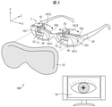
- FIG. 2 is a diagram showing a configuration example of the light irradiation system 100 according to one aspect of the present disclosure.
- the light irradiation system 100 includes a light irradiation device 1 which is a device for irradiating the eyes of a subject with irradiation light in a predetermined wavelength band.
- the light irradiation device 1 may be an installation type device that is difficult to carry, or may be a wearable device.
- the light irradiation system 100 may further include a display device 14 that displays images and various information acquired from the light irradiation device 1 in addition to the light irradiation device 1.
- a display device 14 that displays images and various information acquired from the light irradiation device 1 in addition to the light irradiation device 1.
- the light irradiation system 100 including the display device 14 will be described as an example.
- the light irradiation device 1 When the light irradiation device 1 is a stationary device (see FIG. 5), the light irradiation device 1 includes a support portion 50 that supports a subject in a sitting or lying position.
- the support 50 may be, for example, a chair and a bed.
- the display device 14 may be integrated with the light irradiation device 1, and for example, the display device 14 may be arranged in the light irradiation device 1.
- the light irradiation device 1 when the light irradiation device 1 is a wearable device (see FIG. 2), the light irradiation device 1 has an arbitrary shape (for example, glasses type, goggles type, and headgear) that can be attached to the head of the subject. It may be a mold, etc.).
- the light irradiation device 1 may be provided with a mounting mechanism for mounting on the body of the subject.
- the wearing mechanism may be a nose pad, a temple (a so-called “vine” portion that is hooked on the ear), or the like.
- the wearing mechanism in the case of the goggle type light irradiation device 1 may be a head strap (fixed band) or the like.
- the display device 14 may be a separate body from the light irradiation device 1.
- the display device 14 may be a display unit or a display of a computer (not shown) capable of communicating with the light irradiation device 1.
- the light irradiation device 1 includes an irradiation unit 11 and a shielding mechanism 12. Although not essential, the light irradiation device 1 may further include an image pickup unit 13, a moving mechanism 15, a light receiving unit 16, and a control unit 10. 1 and 2 show a light irradiation device 1 including an image pickup unit 13, a moving mechanism 15, a light receiving unit 16, and a control unit 10 in addition to the irradiation unit 11 and the shielding mechanism 12. Further, the light irradiation device 1 includes a storage unit (not shown) in which various computer programs read by the control unit 10 and data used in various processes executed by the control unit 10 are stored. May be good.
- a light irradiation system a wearable device and an installation capable of irradiating a subject's eyes with light in a predetermined wavelength band to bring about a non-visual effect on the subject's mind and body.
- a type of light irradiation device can be realized.
- the light irradiation device 1 is a glasses-type wearable device.
- the irradiation unit 11 includes one or more light sources for irradiating the eyes of the subject with irradiation light in a predetermined wavelength band.
- the irradiation unit 11 may include, for example, a light emitting element such as a light emitting diode (LED) and a semiconductor laser (LD) as a light source. By using these light emitting elements, the irradiation unit 11 can selectively irradiate monochromatic light having a narrow wavelength width of the light emitting wavelength.
- the irradiation unit 11 may include a light source that emits white light and an optical filter (for example, a bandpass filter) that transmits only light in a predetermined wavelength band. By selecting and using an appropriate optical filter, the irradiation unit 11 can selectively irradiate the irradiation light in a desired wavelength band.
- the light irradiation device 1 shown in FIG. 2 can irradiate both eyes of a subject with light in a predetermined wavelength band, but is not limited to this.
- the light irradiation device 1 may be configured to irradiate one eye of the subject with light in a predetermined wavelength band. In this case, only one light source of the irradiation unit 11 may be turned on.
- the irradiation unit 11 may be detachably attached to the light irradiation device 1 so that the irradiation unit 11 on the unused side can be removed.
- the irradiation unit 11 is arranged in a moving mechanism 15 described later, and the position of the irradiation unit 11 with respect to the position of the eyes of the subject can be changed by using the moving mechanism 15. You may.
- the wavelength band of the irradiation light may be any wavelength band of light that is expected to have an effect of improving the physical and mental condition of the subject by irradiating the eyes of the subject.
- the wavelength band of the irradiation light may be the wavelength band of the green light.
- the wavelength band of the irradiation light is, for example, 450 to 600 nm, and may be 500 to 550 nm.
- the irradiation light may be green light having a peak top of 525 nm.
- the wavelength band of the irradiation light may be the wavelength band of purple light.
- the wavelength band of the irradiation light may be 350 to 410 nm.
- the wavelength band of the irradiation light may be the wavelength band of blue light.
- an optical filter that blocks ultraviolet rays and near-ultraviolet rays may be further provided in order to reduce the damage to the eyes of the subject as much as possible.
- the irradiation light may be continuous light continuously applied to the eyes of the subject, or pulsed light emitted intermittently. May be.
- the light irradiation device 1 includes a shielding mechanism 12.
- a shielding mechanism 12 thereby, when the irradiation light of a predetermined wavelength band is irradiated to the eyes of the subject, the illuminance of the light reaching the eyes of the subject and having a wavelength band different from that of the irradiation light can be reduced.
- the light irradiation device 1 provided with the shielding mechanism 12 can improve the pain relief effect obtained by irradiating the eyes of the subject with green light.
- the shielding mechanism 12 may reduce the illuminance of light different from the irradiation light or the illuminance of light in a wavelength band different from the predetermined wavelength band contained in the light different from the irradiation light.
- the light different from the irradiation light may be, for example, sunlight or light from indoor lighting.
- the shielding mechanism 12 may be made of a cloth or resin having a light-shielding property, or may be made of a metal having a light-shielding property or a light reflecting property.
- the shielding mechanism 12 may include an optical filter that selectively transmits light in a predetermined wavelength band and does not transmit light in a wavelength band different from the predetermined wavelength band.
- the shielding mechanism 12 can reduce the illuminance of the light from the outside of the light irradiation device 1 over the entire wavelength band.
- the shielding mechanism 12 can reduce the illuminance of the light in a wavelength band different from the predetermined wavelength band contained in the light from the outside of the light irradiation device 1.
- the shielding mechanism 12 is made of a light-reflecting material, it is possible to reduce the light from the outside of the light irradiation device 1, while it is also possible to reflect the light inside the light irradiation device 1 to the irradiation target. Is.
- the shielding mechanism 12 may be arranged so that there is no gap between the subject wearing the light irradiation device 1 and the light irradiation device 1. Further, the shielding mechanism 12 may be integrated with the light irradiation device 1 or may be a separate body.
- the shielding mechanism 12 may have a goggle-like shape that covers the entire frame portion of the light irradiation device 1.
- the shielding mechanism 12 can cover the frame portion of the light irradiation device 1.
- the shielding mechanism 12 may be configured to cover the entire head of the subject.
- the target person wearing the light irradiation device 1 shown in FIG. 2, the head of the target person, or the like may be covered with a separate shielding mechanism 12.
- the shielding mechanism 12 shown in FIG. 2 shields the light that reaches both eyes of the subject from the outside of the light irradiation device 1, but is not limited to this.
- the light irradiation device 1 may be configured to include a shielding mechanism 12 for the right eye and a shielding mechanism 12 for the left eye.
- the shielding mechanism 12 on the same side may be used. According to this configuration, the field of view of the eye on the side not irradiated with the irradiation light is not blocked by the shielding mechanism 12. This allows the subject to visually recognize the surrounding situation with the eyes on the side not irradiated with the irradiation light.
- the image pickup unit 13 is a camera for taking an image of a subject, and may be a digital camera or a digital video.
- the image pickup unit 13 may image the face of the subject who is irradiated with the irradiation light, or may image the eyes of the subject who is irradiated with the irradiation light and its surroundings.
- the image data (still image data or moving image data) captured by the image pickup unit 13 may be transmitted from the light irradiation device 1 to the display device 14.
- the image pickup unit 13 may be arranged anywhere as long as it can image the eyes of the subject irradiated with the irradiation light and its surroundings.
- the imaging unit 13 may be arranged in the vicinity of the irradiation unit 11 as shown in FIG. In this case, the position of the imaging unit 13 may be changed by using the moving mechanism 15 together with the irradiation unit 11.
- the moving mechanism 15 accepts an operation for changing the position of the irradiation unit 11 with respect to the position of the subject's eyes (particularly, the pupil).
- the moving mechanism 15 is a mechanism provided for moving the position of the irradiation unit 11 so that the light from the irradiation unit 11 can be irradiated toward the eyes of the subject, particularly the pupil.
- the moving mechanism 15 may have any configuration as long as it is possible to change the position of the irradiation unit 11 with respect to the position of the pupil of the subject's eye.
- the moving mechanism 15 has a holding portion 151 for holding the irradiation portion 11 at the first end 1511 and a guide rail 152 for moving the holding portion 151 in the X-axis direction (left-right direction).
- the direction parallel to the anterior-posterior axis of the eyeball that is, the axis connecting the cornea and the retina
- the direction parallel to the left-right axis that is, the axis connecting the left ear and the right ear
- Is the X-axis direction, and the direction parallel to the vertical axis is the Y-axis direction.
- the guide rail 152 may be, for example, a groove provided in the upper part of the frame of the light irradiation device 1.
- the second end 1512 opposite to the first end 1511 of the holding portion 151 may be slidably abutted on the inner surface of the groove. As a result, the holding portion 151 can move in the X-axis direction along the guide rail 152.
- the moving mechanism 15 may be able to move the position of the irradiation unit 11 in the Y-axis direction (vertical direction).
- the holding portion 151 may have a structure that can be expanded and contracted in the Y-axis direction.
- a fixing member (not shown) that fixes the irradiation unit 11 to the holding portion 151 may be slidable along the holding portion 151, and the irradiation unit 11 may be movable along the holding portion 151.
- a medical person such as a doctor or a nurse in charge of the subject can manually change the position of the irradiation unit 11 along the guide rail 152. Further, the position of the irradiation unit 11 may be automatically changed along the guide rail 152 based on the image data of the image pickup unit 13.
- the light irradiation device 1 can accurately irradiate the eyes of the subject, particularly the pupil, with the irradiation light to reach the fovea centralis of the retina.
- the light receiving unit 16 detects the intensity of the return light of the irradiation light.
- the return light is intended to be light that is reflected on the surface of the eyelid or the like and returns to the irradiation unit 11 when the irradiation light is applied to the eyes or eyelids of the subject from the irradiation unit 11.
- the light receiving unit 16 may be installed at any position as long as it can receive the return light.
- the light receiving unit 16 may include one or more light receiving elements.
- the light receiving unit 16 may include a plurality of light receiving elements in order to detect the intensity of the return light with higher accuracy.
- the light receiving element is an avalanche photodiode.
- an intensity signal output unit (not shown) may be connected to the light receiving unit 16, and the intensity signal output unit is configured to output an intensity signal indicating the intensity of the reflected light detected by the light receiving unit 16. There may be.
- the light receiving unit 16 may be arranged anywhere as long as it can receive the return light.
- the light receiving unit 16 may be provided in the vicinity of the irradiation unit 11 as shown in FIG. In this case, the position of the light receiving unit 16 may be changed by using the moving mechanism 15 together with the irradiation unit 11.
- the display device 14 displays the image captured by the image pickup unit 13.
- the display device 14 may be, for example, a liquid crystal display device or an organic EL display attached to a terminal operated by a medical personnel.
- the display device 14 and the image pickup unit 13 may be connected by wire or wirelessly, but the image captured by the image pickup unit 13 may be displayed on the display device 14 in real time.
- the display device 14 may display an image of the target person captured by the image pickup unit 13. Based on the image displayed on the display device 14, the medical personnel can know the position where the irradiation light is irradiated and the open / closed state of the eyelid of the subject.
- the control unit 10 controls to execute the processing of each function included in the light irradiation device 1.
- the control unit 10 may be a CPU included in the light irradiation device 1.
- the control unit 10 includes an eyelid open / close determination unit 17, a light intensity adjustment unit 18, a calibration unit 19, a time management unit 20, and an output unit 21.
- the light irradiation system 100 can irradiate the eyes of a subject with closed eyes with irradiation light having a predetermined wavelength.
- the illuminance of the irradiation light when it reaches the subject's retina through the eyelids differs depending on whether the eyelids are in the open state or the closed state. Therefore, the light irradiation system 100 may include a control unit 10 and can adjust the illuminance of the irradiation light according to the open / closed state of the eyelids of the subject.
- the eyelid open / close determination unit 17 determines the open / closed state of the target person's eyelids based on the intensity of the return light received by the light receiving unit 16.
- the eyelid opening / closing determination unit 17 may determine the open / closed state of the eyelid of the subject and measure the duration of each of the open state and the closed state of the eyelid of the subject.
- the light intensity adjusting unit 18 Based on the determination result by the eyelid opening / closing determination unit 17, the light intensity adjusting unit 18 irradiates the irradiation unit 11 when the subject's eyelids are closed, as compared with the case where the subject's eyelids are open. The intensity of the irradiation light may be increased.
- the light intensity adjusting unit 18 has a first reference intensity (for example, see the intensity L4 shown in FIG. 3) and a second reference intensity (for example, the intensity shown in FIG. 3), which are predetermined by the calibration process performed by the calibration unit 19 described later. (See L3) may be applied to adjust the intensity of the irradiation light.
- the first reference intensity is the intensity of the irradiation light applied when the subject's eyelids are open
- the second reference intensity is the intensity of the irradiation light applied when the subject's eyelids are in the closed state. It is strength.
- the first reference strength and the second reference strength may be determined for each subject.
- the light intensity adjusting unit 18 may be configured not to increase the intensity of the irradiation light when the subject's eyelids are not closed for a predetermined time or longer.
- an arbitrary fixed value for example, 1 second may be set in advance in seconds.
- the light intensity adjusting unit 18 may be configured to weaken the intensity of the irradiation light when the subject's eyelids are closed for a predetermined time or longer and then opened.
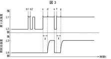
- FIG. 3 is a schematic diagram showing an example of time-dependent changes in the intensity of the return light received by the light receiving unit 16 and the intensity of the irradiation light irradiated by the irradiation unit 11.
- the intensity of the irradiation light and the intensity of the return light are constant until the point b1 in FIG.
- the eyelid opening / closing determination unit 17 determines that the target person's eyelids are in an open state, and the irradiation unit 11 irradiates irradiation light having a predetermined intensity (for example, 4 to 100 Lux).
- a predetermined intensity for example, 4 to 100 Lux.
- the intensity of the irradiation light is 4 to 100 Lux, it is possible to continuously relieve physical pain such as pain felt by the subject without causing the subject to feel glare.
- the predetermined time X in which the subject's eyelids remain closed is preset to 5 seconds as an example.
- the intensity of the return light increased from the intensity L2 to the intensity L1, and at the time of b2, it returned to the intensity L2.
- the eyelid opening / closing determination unit 17 determines that the subject's eyelids are in the closed state at the time of b1, and starts measuring the time for which the eyelids are kept closed.
- the eyelid opening / closing determination unit 17 determines that the subject's eyelids are in the open state at the time of b2. Further, the eyelid opening / closing determination unit 17 measures the time from the time b1 to the time b2 as the time during which the subject's eyelids are kept closed.
- the light intensity adjusting unit 18 compares the time measured by the eyelid opening / closing determination unit 17 (the time during which the subject's eyelids are closed) with the preset predetermined time X (5 seconds). ..
- the light intensity adjusting unit 18 does not change the intensity of the irradiation light at the intensity L4 (first reference intensity) when the time during which the subject's eyelids remain closed is shorter than 5 seconds, which is the predetermined time X. ..
- the light intensity adjusting unit 18 does not change the intensity of the irradiation light when the subject blinks and the eyelids are closed for a very short time.
- the eyelid opening / closing determination unit 17 determines that the subject's eyelids are in the closed state, and starts measuring the duration of the eyelid closing state. Next, the eyelid opening / closing determination unit 17 determines that the target person's eyelids are in the closed state at the time d. Further, the eyelid opening / closing determination unit 17 measures the time from the time c to the time d as the time during which the subject's eyelids are closed.
- the light intensity adjusting unit 18 compares the time measured by the eyelid opening / closing determination unit 17 (the time during which the subject's eyelids are closed) with the predetermined time X.
- the light intensity adjusting unit 18 changes the intensity of the irradiation light from the intensity L4 to the intensity L3 (second reference intensity) when the subject's eyelids are kept closed for a longer time than the predetermined time X.
- the light intensity adjusting unit 18 determines the light intensity irradiated by the irradiation unit 11. Make it stronger.
- the light intensity adjusting unit 18 adjusts the intensity of the irradiation light so that the illuminance of the irradiation light reaching the subject's retina can be increased. It is possible to avoid a significant decrease.
- the e-point corresponds to, for example, when the subject wakes up and opens his eyelids. That is, at the time e, the intensity of the return light is reduced from the intensity L1 to the intensity L2 again.
- the eyelid opening / closing determination unit 17 determines that the subject's eyelids are in the open state, and starts measuring the duration of the eyelid open state.
- the eyelid opening / closing determination unit 17 immediately weakens the light intensity irradiated by the irradiation unit 11.
- the light intensity adjusting unit 18 reduces the intensity of the irradiation light from the intensity L3 to the intensity L4 when the subject's eyelids are closed for a predetermined time or longer and then opened. As a result, it is possible to prevent the intense irradiation light from being applied to the eyes of the awakened subject.
- the intensity of the return light has increased again from the intensity L2 to the intensity L1.
- the eyelid opening / closing determination unit 17 determines that the target person's eyelids are in the closed state at the time f, and starts measuring the time for which the eyelid is kept closed.
- the light intensity adjusting unit 18 changes the light intensity irradiated by the irradiation unit 11 from the intensity L4 to the intensity L3.
- the calibration unit 19 performs the above-mentioned processing for determining the first reference strength and the second reference strength. Specifically, the calibration unit 19 continuously irradiates the eyes of the subject with irradiation light of a predetermined intensity for a certain period of time, and sets the first intensity of the return light detected when the eyelids of the subject are open. , The second intensity of the return light detected in the closed state is acquired.
- the calibration unit 19 has a first reference intensity of irradiation light when the subject's eyelids are open and when the subject's eyelids are closed, based on the results of comparison with the first intensity and the second intensity.
- the second reference intensity of the irradiation light of the above may be determined in advance.
- the first intensity is the intensity of the return light detected by the light receiving unit 16 when the target person's eyelids are open
- the second intensity is the light receiving unit when the target person's eyelids are closed.
- 16 is the intensity of the return light detected.
- the first reference intensity is the intensity of the irradiation light emitted by the irradiation unit 11 to the subject when the subject's eyelids are open
- the second reference intensity is the intensity of the irradiation light when the subject's eyelids are closed. It is the intensity of the irradiation light that the irradiation unit 11 sometimes irradiates the subject.
- the illuminance of the irradiation light that reaches the subject's retina when the subject closes the eyelids differs depending on the condition of the subject's eyelids.
- the state of the eyelid is, for example, the thickness of the eyelid, the presence or absence of a substance present on the surface of the eyelid, and the like. Further, since the thickness of the eyelids varies from subject to subject, the illuminance of the irradiation light reaching the subject's retina differs from subject to subject. Therefore, the first reference strength and the second reference strength may be determined for each subject.
- the calibration unit 19 may determine the first reference strength for each subject. It is known that there are individual differences in the conditions of the cornea, crystalline lens, eyeball, and iris. For example, the curvature of the cornea, the curvature of the crystalline lens, the length of the axis of the eyeball, the accommodation power of the iris, and the degree of turbidity of the crystalline lens are different for each subject. Therefore, even if the irradiation light of the same intensity is irradiated, the illuminance of the irradiation light reaching the retina may differ from subject to subject.
- the calibration unit 19 may determine the first reference intensity to irradiate each subject based on the condition of at least one of the cornea, lens, eyeball, and iris of the subject's eye. For example, in a subject with a large degree of turbidity of the crystalline lens, it is highly possible that the irradiation light of a predetermined intensity does not reach the retina, so that the calibration unit 19 increases the first reference intensity to irradiate the subject. You may decide.
- the calibration unit 19 determines the illuminance of the irradiation light that reaches the subject's retina when each subject is irradiated with the reference irradiation light of a predetermined intensity, the intensity of the irradiation light, and the cornea, crystalline lens, and eyeball of the subject's eye. And may be calculated based on at least one of the states of the iris. Further, the calibration unit 19 may determine the intensity of the irradiation light to be applied to the subject from the relationship between the intensity of the irradiation light and the calculated illuminance. For example, the calibration unit 19 may have data showing the relationship between the intensity of the irradiation light, the state of the cornea, the crystalline lens, the eyeball, and the iris and the illuminance of the irradiation light reaching the retina.
- the state of at least one of the subject's cornea, lens, eyeball, and iris may be, for example, configured to be acquired from the subject's ophthalmic chart information. According to this, it is possible to irradiate the irradiation light of an appropriate intensity for each subject.
- the time management unit 20 measures the intensity of the irradiation light irradiated to the eyes of the subject by the irradiation unit 11 and the integrated time irradiated to the eyes of the subject for each subject.
- the time management unit 20 may be configured to acquire information indicating the time from a timer (not shown) included in the light irradiation device 1, for example.
- the intensity of the irradiation light radiated to the eyes of the subject is, for example, the intensity of the irradiation light when the eyelids of the subject are open (first reference intensity) and the intensity of the irradiation light when the eyelids of the subject are closed. Strength (second standard strength) and the like.
- the integrated time of irradiating the irradiation light may be the integrated time of irradiating the subject with the irradiation light within a predetermined period such as one day, one month, or half a year, and is the integrated time of irradiation in one treatment. You may.
- the output unit 21 outputs, for example, to an external terminal, a server, a storage device, or the like, information indicating the intensity of the irradiation light and the integrated time of irradiation to the eyes of the subject, respectively, measured by the time management unit 20.
- the light irradiation system 100 includes an irradiation unit 11 that irradiates the eyes of a subject with irradiation light in a predetermined wavelength band, and at least a predetermined wavelength band included in light different from the irradiation light. It is provided with a shielding mechanism 12 that reduces the illuminance of light in a wavelength band different from that of the above.
- the light irradiation system 100 can irradiate the eyes of the subject with irradiation light of a predetermined wavelength band, and at the same time, light in a wavelength band different from the predetermined wavelength band penetrates into the eyes of the subject. Can be prevented.
- the light irradiation system 100 it is possible to irradiate the eyes of a subject with a predetermined wavelength band to effectively bring about an action on the mind and body of the subject.
- the light irradiation system 100 further includes an imaging unit 13 that captures an image of the subject, and a display device 14 that allows a medical person or the subject to visually recognize an image of the subject's eyes imaged by the imaging unit 13. You may. Further, the light irradiation system 100 may further include a moving mechanism 15 for receiving an operation for changing the position of the irradiation unit 11 with respect to the position of the eyes of the subject.
- the irradiation light is applied to the fovea centralis of the subject's eye where the pyramidal cells are concentrated. It may be incident.
- the light irradiation system 100 includes an imaging unit 13, a display device 14, and a moving mechanism 15, so that the medical personnel or the subject can check the position of the irradiation unit while checking the displayed image of the subject's eyes. , Can be moved to an appropriate position using the moving mechanism 15. As a result, the medical personnel or the subject can efficiently inject the irradiation light into the fovea centralis.
- the light irradiation system 100 may further include a light receiving unit 16 that detects the intensity of the return light of the irradiation light, and an eyelid open / close determination unit 17 that determines the open / closed state of the eyelid of the subject based on the intensity of the return light. .. Further, the light irradiation system 100 determines the intensity of the irradiation light when the subject's eyelids are closed, as compared with the case where the subject's eyelids are open, based on the determination result by the eyelid opening / closing determination unit 17. A light intensity adjusting unit 18 for intensifying may be further provided.
- the magnitude of the effect of irradiating the subject's eye with irradiation light in a predetermined wavelength band depends on the illuminance when the irradiation light reaches the retina of the subject's eye.
- the illuminance of the irradiation light reaching the subject's retina is extremely reduced.
- the irradiation light is blocked by the eyelids, so that the illuminance when reaching the retina may be significantly reduced.
- the light irradiation system 100 includes a light receiving unit 16, an eyelid open / close determination unit 17, and a light intensity adjusting unit 18 to determine the open / closed state of the target person's eyelids based on the intensity of the return light of the irradiation light.
- the intensity of the irradiation light can be adjusted based on the determination result of the open / closed state.
- the light irradiation system 100 has a time management unit 20 that measures the intensity of the irradiation light radiated to the eyes of the subject and the integrated time of irradiation for each subject, and the measured intensity of the irradiation light and the integrated time.
- An output unit 21 for outputting the respective indicated information may be further provided.
- the medical personnel manages the integrated illuminance of the irradiation light received by the subject for each subject, and determines the magnitude of the effect of irradiating the subject's eyes with the irradiation light for each subject. Can be evaluated.
- the configuration shown in FIG. 1 is an example and is not limited to this.
- the light irradiation system 100 may further include a server device that receives and manages the ID of each subject and the information measured by the time management unit 20.
- FIG. 4 is a flowchart showing a flow of processing executed by the light irradiation system 100 according to the present embodiment.
- the calibration unit 19 performs the above-mentioned calibration process, and determines the first reference intensity and the second reference intensity, which are the intensities of the irradiation light irradiated by the irradiation unit 11 (calibration step).
- the irradiation unit 11 irradiates light of the first reference intensity and proceeds to S103 (light irradiation step).
- the eyelid opening / closing determination unit 17 determines whether or not the target person's eyelids are in the closed state. When the eyelid opening / closing determination unit 17 determines that the target person's eyelids are in the closed state (YES in S103), the process proceeds to S104. When the eyelid opening / closing determination unit 17 determines that the subject's eyelids are not in the closed state, that is, in the open state (NO in S103), the process returns to S102, and the irradiation unit 11 irradiates light of the first reference intensity. continue.
- the eyelid open / close determination unit 17 starts time measurement and proceeds to S105.
- the time management unit 20 may perform the time measurement as an example.
- the eyelid opening / closing determination unit 17 determines whether or not a predetermined time has elapsed since the time measurement was started in S104 (time determination step). At this time, the time management unit 20 may determine whether or not the predetermined time has elapsed. When the predetermined time has elapsed (YES in S105), the process proceeds to S106. If the predetermined time has not elapsed (NO in S105), the process returns to S102, and the irradiation unit 11 continues to irradiate the light of the first reference intensity.
- the light intensity adjusting unit 18 changes the intensity of the irradiation light irradiated by the irradiation unit 11 from the first reference intensity to the second reference intensity, and proceeds to S107 (first intensity change step). That is, it is conceivable that the subject fell asleep, for example, because the subject's eyelids were closed for a predetermined time or longer.
- the irradiation unit 11 irradiates the retina of the subject with light having a second reference intensity, which is stronger than the first reference intensity, so that the light having the same illuminance as in the open state reaches the retina of the subject.
- the irradiation unit 11 continues the light irradiation of the second reference intensity and proceeds to S108.
- the eyelid opening / closing determination unit 17 determines whether or not the target person's eyelids are in the open state. When the eyelid opening / closing determination unit 17 determines that the target person's eyelids are in the open state (YES in S108), the process proceeds to S109. When the eyelid opening / closing determination unit 17 determines that the subject's eyelids are not in the open state, that is, in the closed state (NO in S108), the process returns to S107, and the irradiation unit 11 irradiates light of the second reference intensity. continue.
- the light intensity adjusting unit 18 changes the intensity of the irradiation light irradiated by the irradiation unit 11 from the second reference intensity to the first reference intensity (second intensity change step).
- the light irradiation system 100 determines whether or not to end the light irradiation, and if the end of the light irradiation is accepted (YES in S110), the irradiation unit 11 ends the light irradiation.
- the irradiation unit 11 returns to S102 and continues the processing from S102 to S110.
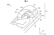
- FIG. 5 is a perspective view showing a configuration example of the light irradiation system 100a according to the second embodiment.
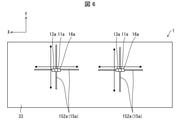
- FIG. 6 is a bottom view showing a configuration example of the light irradiation system 100a according to the second embodiment.
- the light irradiation device 1a is a stationary device.
- the light irradiation device 1a includes an irradiation unit 11a and a shielding mechanism 12a, similarly to the light irradiation device 1. Further, the light irradiation device 1a further includes a support portion 50 for supporting the subject in the sitting position or the lying position.
- the irradiation unit 11a will be described later with reference to FIG.
- the light irradiation device 1a may further include a display device 14a and a control unit 10a as shown in FIG. Further, the light irradiation device 1a may further include an image pickup unit 13a, a moving mechanism 15a, and a light receiving unit 16a. The image pickup unit 13a, the moving mechanism 15a, and the light receiving unit 16a will be described later with reference to FIG.
- the support portion 50 of the light irradiation device 1a is a bed as an example.
- the shielding mechanism 12a is a half-pipe type in which an insertion hole 40, which is a hole, is provided inside.
- the insertion hole 40 is a portion surrounded by the inner peripheral surface 33 and the support portion 50, and is a hole for the subject to insert the head.
- a shielding portion 121 is installed at the entrance of the insertion hole 40 into which the subject inserts the head, and the shielding portion 121 is installed on the same surface as the outer surface 32 of the shielding mechanism 12a and is joined to the end portion of the outer surface 32.
- the shielding portion 121 may be made of a cloth having a light-shielding property so that the subject can easily move the head in and out.
- the display device 14a corresponds to the display device 14 in the first embodiment.
- the display device 14a may be installed on the outer peripheral surface 31 of the light irradiation device 1a.
- the control unit 10a corresponds to the control unit 10 in the first embodiment, and controls to execute the processing of each function included in the light irradiation device 1a.
- FIG. 6 is a schematic view showing an inner peripheral surface 33 ahead of the line of sight A seen from the subject when the subject inserts his / her head into the insertion hole 40 of the light irradiation device 1a of FIG.
- the irradiation unit 11a, the image pickup unit 13a, the moving mechanism 15a, and the light receiving unit 16a are installed on the inner peripheral surface 33 of the shielding mechanism 12a.
- the irradiation unit 11a corresponds to the irradiation unit 11 of the first embodiment.
- the irradiation unit 11a is installed at a position facing the eyes of the subject in the shielding mechanism 12a. Specifically, if the irradiation unit 11a is installed on the inner peripheral surface 33 of the shielding mechanism 12a and is installed at a position facing the eyes of the subject when the subject inserts the head into the insertion hole 40. good.
- the image pickup unit 13a corresponds to the image pickup unit 13 of the first embodiment.
- the image data captured by the image pickup unit 13a may be transmitted to the display device 14a installed on the outer peripheral surface 31 described above. As shown in FIG.
- the image pickup unit 13a may be arranged in the vicinity of the irradiation unit 11a, and in this case, the position of the image pickup unit 13a can be changed together with the irradiation unit 11a by using the moving mechanism 15a. It may be.
- the moving mechanism 15a may be a guide rail 152a for moving the irradiation unit 11a in the X-axis direction (horizontal direction) and the Y-axis direction (vertical direction).
- the direction parallel to the anterior-posterior axis of the eyeball is the Z-axis direction
- the left-right axis that is, the axis connecting the left ear and the right ear
- the direction parallel to the X-axis direction is defined as the X-axis direction
- the direction parallel to the vertical axis that is, the axis connecting the head and the side portion
- the Y-axis direction is defined as the Y-axis direction.
- the irradiation unit 11a is held by the first end (corresponding to the first end 1511 of the first embodiment and FIG. 2) of the holding portion (not shown), and the second holding portion is held.
- the end (corresponding to the second end 1512 of the first embodiment and the second embodiment) may be configured to move on the guide rail 152a.
- the light receiving unit 16a corresponds to the light receiving unit 16 of the first embodiment. As shown in FIG. 6, the light receiving unit 16a may be provided in the vicinity of the irradiation unit 11a, or may be changed by using the moving mechanism 15a together with the irradiation unit 11a.
- control blocks (control units 10, 10a) of the light irradiation systems 100 and 100a may be realized by a logic circuit (hardware) formed in an integrated circuit (IC chip) or the like, or may be realized by software. ..
- the light irradiation systems 100 and 100a include a computer that executes a program command that is software that realizes each function.
- the computer includes, for example, one or more processors and a computer-readable recording medium that stores the program. Then, in the computer, the processor reads the program from the recording medium and executes the program, thereby achieving the object of the present disclosure.
- the processor for example, a CPU (Central Processing Unit) can be used.
- the recording medium in addition to a “non-temporary tangible medium” such as a ROM (Read Only Memory), a tape, a disk, a card, a semiconductor memory, a programmable logic circuit, or the like can be used.
- a RAM RandomAccessMemory
- the program may be supplied to the computer via any transmission medium (communication network, broadcast wave, etc.) capable of transmitting the program.
- transmission medium communication network, broadcast wave, etc.
- One aspect of the present disclosure may also be realized in the form of a data signal embedded in a carrier wave, in which the program is embodied by electronic transmission.
Abstract
The present invention realizes a light irradiation system and light irradiation device for irradiating eyes of a subject with light having a predetermined wavelength band to provide, with a non-visual effect, the body and mind of the subject. The light irradiation system according to one aspect of the present disclosure comprises: an irradiation part for irradiating eyes of a subject with irradiation light having a predetermined wavelength band; and a shielding mechanism for decreasing the illuminance of light different from the irradiation light or decreasing the illuminance of light having a wavelength band which is included in light different from the irradiation light and is different from the predetermined wavelength band.
Description
本開示は光照射システム、ウェアラブル装置、設置型の光照射装置および光照射方法に関する。
This disclosure relates to a light irradiation system, a wearable device, a stationary light irradiation device, and a light irradiation method.
眼には光受容能を有するものの、視覚機能に対する直接的な関連性を有さない、内因性光感受性網膜神経節細胞(iPRGC:intrinsically photosensitive retinal ganglion cell)等の神経節細胞が存在する。
There are ganglion cells such as intrinsically photosensitive retinal ganglion cells (iPRGC) in the eye, which have photoacceptive ability but do not have a direct relationship with visual function.
内因性光感受性網膜神経節細胞が光を受容すると、心身にさまざまな非視覚的な作用をもたらすことが知られている。例えば、非特許文献1には、緑色の光に該当する波長帯の光を照射することで、急性および慢性の痛みが緩和されることが報告されている。
It is known that when intrinsic light-sensitive retinal ganglion cells receive light, they bring about various non-visual effects on the mind and body. For example, Non-Patent Document 1 reports that acute and chronic pain is alleviated by irradiating light in a wavelength band corresponding to green light.
本開示の一態様に係る光照射システムは、対象者の眼に所定の波長帯の照射光を照射する照射部と、前記照射光とは異なる光に含まれる、少なくとも前記所定の波長帯とは異なる波長帯の光の照度を減じる遮蔽機構と、を備える。
The light irradiation system according to one aspect of the present disclosure includes an irradiation unit that irradiates the eyes of a subject with irradiation light in a predetermined wavelength band, and at least the predetermined wavelength band contained in light different from the irradiation light. It is equipped with a shielding mechanism that reduces the illuminance of light in different wavelength bands.
本開示の一態様に係るウェアラブル装置は、対象者の頭部に装着するウェアラブル装置であって、前記対象者の眼に所定の波長帯の照射光を照射する照射部と、前記対象者の眼に達する、前記照射光とは異なる光に含まれる、少なくとも前記所定の波長帯とは異なる波長帯の光の照度を減じる遮蔽機構と、を備える。
The wearable device according to one aspect of the present disclosure is a wearable device worn on the head of the subject, and includes an irradiation unit that irradiates the eyes of the subject with irradiation light of a predetermined wavelength band and the eyes of the subject. It is provided with a shielding mechanism for reducing the illuminance of light in a wavelength band different from the predetermined wavelength band, which is contained in the light different from the irradiation light.
本開示の一態様に係る設置型の光照射装置は、座位または臥位の利用者を支持する支持部と、対象者の眼に所定の波長帯の照射光を照射する照射部と、前記対象者の眼に達する、前記照射光とは異なる光に含まれる、少なくとも前記所定の波長帯とは異なる波長帯の光の照度を減じる遮蔽機構と、を備え、前記照射部は、前記遮蔽機構における前記対象者の眼に対向する位置に設置される。
The stationary light irradiation device according to one aspect of the present disclosure includes a support portion that supports a sitting or lying user, an irradiation portion that irradiates the eyes of a subject with irradiation light in a predetermined wavelength band, and the subject. The irradiation unit includes a shielding mechanism that reduces the illuminance of light in a wavelength band different from the predetermined wavelength band, which is contained in light different from the irradiation light and reaches the human eye. It is installed at a position facing the subject's eyes.
本開示の一態様に係る光照射方法は、対象者の眼に所定の強度の照射光を一定期間継続照射し、該対象者の瞼が開状態である場合に検出される戻り光の第1強度と、閉状態である場合に検出される前記戻り光の第2強度とを取得し、前記第1強度および前記第2強度との比較結果に基づいて、前記対象者の瞼が開状態であるときの前記照射光の第1基準強度と、前記対象者の瞼が閉状態であるときの前記照射光の第2基準強度とを予め決定する較正ステップと、前記第1基準強度の光を照射する光照射ステップと、前記対象者の瞼が閉状態であるか否か、および前記閉状態で所定時間が経過したか否かを判定し、前記照射光の強度を前記第1基準強度から前記第2基準強度に変更する第1の強度変更ステップと、前記対象者の瞼が開状態であるか否かを判定し、前記照射光の強度を前記第2基準強度から前記第1基準強度に変更する第2の強度変更ステップと、を含む。
In the light irradiation method according to one aspect of the present disclosure, the first type of return light detected when the subject's eyes are continuously irradiated with irradiation light of a predetermined intensity for a certain period of time and the subject's eyelids are open. The intensity and the second intensity of the return light detected in the closed state are acquired, and based on the comparison result between the first intensity and the second intensity, the subject's eyelids are in the open state. A calibration step for predetermining the first reference intensity of the irradiation light at a certain time and the second reference intensity of the irradiation light when the eyelids of the subject are closed, and the light of the first reference intensity. The light irradiation step to irradiate, whether or not the subject's eyelids are closed, and whether or not a predetermined time has elapsed in the closed state are determined, and the intensity of the irradiation light is determined from the first reference intensity. The first intensity change step for changing to the second reference intensity and whether or not the eyelids of the subject are in the open state are determined, and the intensity of the irradiation light is changed from the second reference intensity to the first reference intensity. Includes a second intensity change step, which changes to.
〔実施形態1〕
以下、本開示の一実施形態について、詳細に説明する。本明細書において特記しない限り、数値範囲を表す「A~B」は、「A以上B以下」を意味する。 [Embodiment 1]
Hereinafter, one embodiment of the present disclosure will be described in detail. Unless otherwise specified in the present specification, "A to B" representing a numerical range means "A or more and B or less".
以下、本開示の一実施形態について、詳細に説明する。本明細書において特記しない限り、数値範囲を表す「A~B」は、「A以上B以下」を意味する。 [Embodiment 1]
Hereinafter, one embodiment of the present disclosure will be described in detail. Unless otherwise specified in the present specification, "A to B" representing a numerical range means "A or more and B or less".
(光照射システム100の構成)
まず、光照射システム100の構成について、図1および図2を用いて説明する。図1は、本開示の実施形態1に係る光照射システム100の要部構成の一例を示すブロック図である。図2は、本開示の一態様に係る光照射システム100の構成例を示す図である。 (Configuration of light irradiation system 100)
First, the configuration of thelight irradiation system 100 will be described with reference to FIGS. 1 and 2. FIG. 1 is a block diagram showing an example of the configuration of a main part of the light irradiation system 100 according to the first embodiment of the present disclosure. FIG. 2 is a diagram showing a configuration example of the light irradiation system 100 according to one aspect of the present disclosure.
まず、光照射システム100の構成について、図1および図2を用いて説明する。図1は、本開示の実施形態1に係る光照射システム100の要部構成の一例を示すブロック図である。図2は、本開示の一態様に係る光照射システム100の構成例を示す図である。 (Configuration of light irradiation system 100)
First, the configuration of the
光照射システム100は、対象者の眼に所定の波長帯の照射光を照射するための装置である光照射装置1を備えている。光照射装置1は、携帯することが困難な設置型の装置であってもよいし、ウェアラブル装置であってもよい。
The light irradiation system 100 includes a light irradiation device 1 which is a device for irradiating the eyes of a subject with irradiation light in a predetermined wavelength band. The light irradiation device 1 may be an installation type device that is difficult to carry, or may be a wearable device.
光照射システム100は、光照射装置1に加えて、光照射装置1から取得した画像および各種情報を表示する表示装置14をさらに備えていてもよい。以下では、表示装置14を備える光照射システム100を例に挙げて説明する。
The light irradiation system 100 may further include a display device 14 that displays images and various information acquired from the light irradiation device 1 in addition to the light irradiation device 1. Hereinafter, the light irradiation system 100 including the display device 14 will be described as an example.
光照射装置1が設置型の装置である場合(図5参照)、光照射装置1は座位または臥位の対象者を支持する支持部50を含む。支持部50は、例えば、椅子およびベッドであってよい。光照射装置1が設置型の装置である場合については、後に具体例を挙げて説明する。この場合、表示装置14は、光照射装置1と一体であってもよく、例えば、表示装置14は、光照射装置1に配設されていてもよい。
When the light irradiation device 1 is a stationary device (see FIG. 5), the light irradiation device 1 includes a support portion 50 that supports a subject in a sitting or lying position. The support 50 may be, for example, a chair and a bed. The case where the light irradiation device 1 is a stationary device will be described later with a specific example. In this case, the display device 14 may be integrated with the light irradiation device 1, and for example, the display device 14 may be arranged in the light irradiation device 1.
一方、光照射装置1がウェアラブル装置である場合(図2参照)、光照射装置1は、対象者の頭部に装着させることが可能な任意の形状(例えば、メガネ型、ゴーグル型、およびヘッドギア型等)であってもよい。この場合、光照射装置1は、対象者の身体に装着させるための装着機構を備えていてもよい。例えば、メガネ型の光照射装置1の場合の装着機構は、鼻パッドおよびテンプル(耳に引っ掛ける、いわゆる「つる」の部分)等であってもよい。また、ゴーグル型の光照射装置1の場合の装着機構は、頭部ストラップ(固定バンド)等であってもよい。図2に示すように、光照射装置1がウェアラブル装置である場合、表示装置14は、光照射装置1と別体であってもよい。例えば、表示装置14は、光照射装置1と通信可能なコンピュータ(図示せず)の表示部、またはディスプレイであってもよい。
On the other hand, when the light irradiation device 1 is a wearable device (see FIG. 2), the light irradiation device 1 has an arbitrary shape (for example, glasses type, goggles type, and headgear) that can be attached to the head of the subject. It may be a mold, etc.). In this case, the light irradiation device 1 may be provided with a mounting mechanism for mounting on the body of the subject. For example, in the case of the glasses-type light irradiation device 1, the wearing mechanism may be a nose pad, a temple (a so-called “vine” portion that is hooked on the ear), or the like. Further, the wearing mechanism in the case of the goggle type light irradiation device 1 may be a head strap (fixed band) or the like. As shown in FIG. 2, when the light irradiation device 1 is a wearable device, the display device 14 may be a separate body from the light irradiation device 1. For example, the display device 14 may be a display unit or a display of a computer (not shown) capable of communicating with the light irradiation device 1.
図1に示すように、光照射装置1は、照射部11および遮蔽機構12を備えている。光照射装置1は、必須では無いが、撮像部13、移動機構15、受光部16、および制御部10をさらに備えていてもよい。図1および図2には、照射部11および遮蔽機構12に加え、撮像部13、移動機構15、受光部16、および制御部10を備える光照射装置1を示している。また、光照射装置1は、制御部10によって読み出される各種コンピュータプログラム、および、制御部10が実行する各種処理において利用されるデータなどが格納されている記憶部(図示せず)を備えていてもよい。
As shown in FIG. 1, the light irradiation device 1 includes an irradiation unit 11 and a shielding mechanism 12. Although not essential, the light irradiation device 1 may further include an image pickup unit 13, a moving mechanism 15, a light receiving unit 16, and a control unit 10. 1 and 2 show a light irradiation device 1 including an image pickup unit 13, a moving mechanism 15, a light receiving unit 16, and a control unit 10 in addition to the irradiation unit 11 and the shielding mechanism 12. Further, the light irradiation device 1 includes a storage unit (not shown) in which various computer programs read by the control unit 10 and data used in various processes executed by the control unit 10 are stored. May be good.
本開示の一態様によれば、所定の波長帯の光を対象者の眼に照射して、該対象者の心身に非視覚的な作用をもたらすことが可能な光照射システム、ウェアラブル装置および設置型の光照射装置を実現することができる。
According to one aspect of the present disclosure, a light irradiation system, a wearable device and an installation capable of irradiating a subject's eyes with light in a predetermined wavelength band to bring about a non-visual effect on the subject's mind and body. A type of light irradiation device can be realized.
以下では、光照射装置1が、メガネ型のウェアラブル装置である場合を例に挙げて説明する。
In the following, a case where the light irradiation device 1 is a glasses-type wearable device will be described as an example.
<照射部11>
照射部11は、対象者の眼に所定の波長帯の照射光を照射するための1以上の光源を備えている。照射部11は、例えば、発光ダイオード(LED)および半導体レーザ(LD)などの発光素子を光源として備えていてもよい。これらの発光素子を使用することにより、照射部11は、発光波長の波長幅が狭い単色光を選択的に照射することができる。あるいは、照射部11は、白色光を発する光源と、所定の波長帯の光のみを透過させる光学フィルタ(例えば、バンドパスフィルタ)とを備えていてもよい。適切な光学フィルタを選択して用いることにより、照射部11は、所望の波長帯の照射光を選択的に照射することができる。 <Irradiation unit 11>
Theirradiation unit 11 includes one or more light sources for irradiating the eyes of the subject with irradiation light in a predetermined wavelength band. The irradiation unit 11 may include, for example, a light emitting element such as a light emitting diode (LED) and a semiconductor laser (LD) as a light source. By using these light emitting elements, the irradiation unit 11 can selectively irradiate monochromatic light having a narrow wavelength width of the light emitting wavelength. Alternatively, the irradiation unit 11 may include a light source that emits white light and an optical filter (for example, a bandpass filter) that transmits only light in a predetermined wavelength band. By selecting and using an appropriate optical filter, the irradiation unit 11 can selectively irradiate the irradiation light in a desired wavelength band.
照射部11は、対象者の眼に所定の波長帯の照射光を照射するための1以上の光源を備えている。照射部11は、例えば、発光ダイオード(LED)および半導体レーザ(LD)などの発光素子を光源として備えていてもよい。これらの発光素子を使用することにより、照射部11は、発光波長の波長幅が狭い単色光を選択的に照射することができる。あるいは、照射部11は、白色光を発する光源と、所定の波長帯の光のみを透過させる光学フィルタ(例えば、バンドパスフィルタ)とを備えていてもよい。適切な光学フィルタを選択して用いることにより、照射部11は、所望の波長帯の照射光を選択的に照射することができる。 <
The
図2に示す光照射装置1は、所定の波長帯の光を対象者の両眼に照射可能であるが、これに限定されない。光照射装置1は、対象者の片方の眼に、所定の波長帯の光を照射する構成であってもよい。この場合、照射部11の一方の光源のみを点灯させる構成であってもよい。あるいは、照射部11が光照射装置1に着脱自在に取り付けられており、使用しない側の照射部11を取り外すことが可能であってもよい。
The light irradiation device 1 shown in FIG. 2 can irradiate both eyes of a subject with light in a predetermined wavelength band, but is not limited to this. The light irradiation device 1 may be configured to irradiate one eye of the subject with light in a predetermined wavelength band. In this case, only one light source of the irradiation unit 11 may be turned on. Alternatively, the irradiation unit 11 may be detachably attached to the light irradiation device 1 so that the irradiation unit 11 on the unused side can be removed.
照射部11は、図2に示すように、後述する移動機構15に配されており、対象者の眼の位置に対する照射部11の位置は、移動機構15を用いて変更することが可能であってもよい。
As shown in FIG. 2, the irradiation unit 11 is arranged in a moving mechanism 15 described later, and the position of the irradiation unit 11 with respect to the position of the eyes of the subject can be changed by using the moving mechanism 15. You may.
[照射光の波長帯]
照射光の波長帯は、対象者の眼に照射することで、該対象者の心身の状態を改善させる効果が期待される光の波長帯であればよい。 [Wavelength band of irradiation light]
The wavelength band of the irradiation light may be any wavelength band of light that is expected to have an effect of improving the physical and mental condition of the subject by irradiating the eyes of the subject.
緑色光を対象者の眼に照射することによって、照射後において、該対象者が感じている疼痛等の身体の痛みを持続的に緩和することが可能である。それゆえ、照射光の波長帯は、緑色光の波長帯であってもよい。この場合、照射光の波長帯は、例えば、450~600nmであり、500~550nmであってもよい。照射光は、ピークトップが525nmの緑色光であってもよい。
By irradiating the eyes of the subject with green light, it is possible to continuously relieve physical pain such as pain felt by the subject after irradiation. Therefore, the wavelength band of the irradiation light may be the wavelength band of the green light. In this case, the wavelength band of the irradiation light is, for example, 450 to 600 nm, and may be 500 to 550 nm. The irradiation light may be green light having a peak top of 525 nm.
紫色光を対象者の眼に照射することによって、該対象者の視力の低下の虞を低減したり、近視の進行速度を低下させたりすることが可能である。それゆえ、照射光の波長帯は、紫色光の波長帯であってもよい。この場合、照射光の波長帯は、350~410nmであってもよい。
By irradiating the subject's eyes with purple light, it is possible to reduce the risk of deterioration of the subject's visual acuity and reduce the rate of myopia progression. Therefore, the wavelength band of the irradiation light may be the wavelength band of purple light. In this case, the wavelength band of the irradiation light may be 350 to 410 nm.
また、青色光を対象者の眼に照射することによって、該対象者の時差ボケの症状を緩和できることが可能である。それゆえ、照射光の波長帯は、青色光の波長帯であってもよい。ただし、青色光を対象者の眼に照射する場合、該対象者の眼に与えるダメージを少しでも低減させるために、紫外線および近紫外線を遮断する光学フィルタをさらに備えてもよい。
Further, by irradiating the subject's eyes with blue light, it is possible to alleviate the symptoms of jet lag of the subject. Therefore, the wavelength band of the irradiation light may be the wavelength band of blue light. However, when irradiating the eyes of the subject with blue light, an optical filter that blocks ultraviolet rays and near-ultraviolet rays may be further provided in order to reduce the damage to the eyes of the subject as much as possible.
対象者の心身の状態を改善させる効果が期待されるのであれば、照射光は、対象者の眼に連続して照射される連続光であってもよいし、間欠的に照射されるパルス光であってもよい。
If the effect of improving the physical and mental condition of the subject is expected, the irradiation light may be continuous light continuously applied to the eyes of the subject, or pulsed light emitted intermittently. May be.
<遮蔽機構12>
本開示に係る光照射装置1は、遮蔽機構12を備えている。これにより、所定の波長帯の照射光を対象者の眼に照射する場合、該対象者の眼に到達する、少なくとも照射光とは異なる波長帯の光の照度を低減させることができる。例えば、緑色光を対象者の眼に照射することで、照射後に痛み緩和効果を持続させることが可能である。遮蔽機構12を備える光照射装置1は、緑色光を対象者の眼に照射することによって得られる痛み緩和効果を向上させることができる。 <Shielding mechanism 12>
Thelight irradiation device 1 according to the present disclosure includes a shielding mechanism 12. Thereby, when the irradiation light of a predetermined wavelength band is irradiated to the eyes of the subject, the illuminance of the light reaching the eyes of the subject and having a wavelength band different from that of the irradiation light can be reduced. For example, by irradiating the eyes of a subject with green light, it is possible to maintain the pain-relieving effect after irradiation. The light irradiation device 1 provided with the shielding mechanism 12 can improve the pain relief effect obtained by irradiating the eyes of the subject with green light.
本開示に係る光照射装置1は、遮蔽機構12を備えている。これにより、所定の波長帯の照射光を対象者の眼に照射する場合、該対象者の眼に到達する、少なくとも照射光とは異なる波長帯の光の照度を低減させることができる。例えば、緑色光を対象者の眼に照射することで、照射後に痛み緩和効果を持続させることが可能である。遮蔽機構12を備える光照射装置1は、緑色光を対象者の眼に照射することによって得られる痛み緩和効果を向上させることができる。 <
The
遮蔽機構12は、照射光とは異なる光の照度、または、照射光とは異なる光に含まれる、所定の波長帯とは異なる波長帯の光の照度を減じてもよい。ここで、照射光とは異なる光とは、例えば、太陽光、および屋内の照明からの光であってもよい。
The shielding mechanism 12 may reduce the illuminance of light different from the irradiation light or the illuminance of light in a wavelength band different from the predetermined wavelength band contained in the light different from the irradiation light. Here, the light different from the irradiation light may be, for example, sunlight or light from indoor lighting.
遮蔽機構12は、遮光性を有する布製、樹脂製であってもよいし、遮光性または光反射性を有する金属製であってもよい。あるいは、遮蔽機構12は、所定の波長帯の光を選択的に透過し、所定の波長帯とは異なる波長帯の光を透過しない光学フィルタを備えていてもよい。前者の場合、遮蔽機構12は、光照射装置1の外部からの光の照度を全波長帯に亘り減じることができる。後者の場合、遮蔽機構12は、光照射装置1の外部からの光に含まれる、所定の波長帯とは異なる波長帯の光の照度を減じることができる。これにより、所定の波長帯の照射光を対象者の眼に照射するときに、該対象者の眼に到達する、照射光とは異なる波長帯の光の照度を低減させることができる。遮蔽機構12が、光反射性の材料から成る場合には、光照射装置1の外部からの光を減じることができる一方で、光照射装置1の内部の光を照射対象へ反射することも可能である。
The shielding mechanism 12 may be made of a cloth or resin having a light-shielding property, or may be made of a metal having a light-shielding property or a light reflecting property. Alternatively, the shielding mechanism 12 may include an optical filter that selectively transmits light in a predetermined wavelength band and does not transmit light in a wavelength band different from the predetermined wavelength band. In the former case, the shielding mechanism 12 can reduce the illuminance of the light from the outside of the light irradiation device 1 over the entire wavelength band. In the latter case, the shielding mechanism 12 can reduce the illuminance of the light in a wavelength band different from the predetermined wavelength band contained in the light from the outside of the light irradiation device 1. Thereby, when the irradiation light of a predetermined wavelength band is irradiated to the eyes of the subject, the illuminance of the light of a wavelength band different from the irradiation light that reaches the eyes of the subject can be reduced. When the shielding mechanism 12 is made of a light-reflecting material, it is possible to reduce the light from the outside of the light irradiation device 1, while it is also possible to reflect the light inside the light irradiation device 1 to the irradiation target. Is.
遮蔽機構12は、光照射装置1を装着した対象者と、光照射装置1との間の隙間が生じないように配置されればよい。また、遮蔽機構12は、光照射装置1と一体であってもよく、別体であってもよい。
The shielding mechanism 12 may be arranged so that there is no gap between the subject wearing the light irradiation device 1 and the light irradiation device 1. Further, the shielding mechanism 12 may be integrated with the light irradiation device 1 or may be a separate body.
遮蔽機構12は、図2に示すように、光照射装置1のフレーム部分全体を覆うゴーグル様の形状を有していてもよい。この場合、遮蔽機構12は、光照射装置1のフレーム部分を覆うことができる。これにより、光照射装置1の外部からの光が、対象者の額、こめかみ、頬、および鼻と、光照射装置1との間の隙間から侵入し、該対象者の眼に到達することを回避することができる。あるいは、遮蔽機構12は、対象者の頭部全体を覆う構成であってもよい。また、図2に示す光照射装置1を装着した対象者または対象者の頭部などを、別体の遮蔽機構12によって覆う構成であってもよい。
As shown in FIG. 2, the shielding mechanism 12 may have a goggle-like shape that covers the entire frame portion of the light irradiation device 1. In this case, the shielding mechanism 12 can cover the frame portion of the light irradiation device 1. As a result, light from the outside of the light irradiation device 1 enters through the gap between the subject's forehead, temples, cheeks, and nose and the light irradiation device 1, and reaches the subject's eyes. It can be avoided. Alternatively, the shielding mechanism 12 may be configured to cover the entire head of the subject. Further, the target person wearing the light irradiation device 1 shown in FIG. 2, the head of the target person, or the like may be covered with a separate shielding mechanism 12.
図2に示す遮蔽機構12は、光照射装置1の外部から対象者の両眼に到達する光を遮蔽するが、これに限定されない。例えば、光照射装置1が、右眼用の遮蔽機構12および左眼用の遮蔽機構12を備える構成であってもよい。この場合、照射光を対象者の片方の眼に照射している場合には、同じ側の遮蔽機構12のみを用いてもよい。この構成によれば、照射光を照射されていない側の眼の視界は、遮蔽機構12によって遮られない。これにより、対象者は、照射光を照射されていない側の眼によって周囲の状況を視認することが可能である。
The shielding mechanism 12 shown in FIG. 2 shields the light that reaches both eyes of the subject from the outside of the light irradiation device 1, but is not limited to this. For example, the light irradiation device 1 may be configured to include a shielding mechanism 12 for the right eye and a shielding mechanism 12 for the left eye. In this case, when the irradiation light is applied to one eye of the subject, only the shielding mechanism 12 on the same side may be used. According to this configuration, the field of view of the eye on the side not irradiated with the irradiation light is not blocked by the shielding mechanism 12. This allows the subject to visually recognize the surrounding situation with the eyes on the side not irradiated with the irradiation light.
<撮像部13>
撮像部13は、対象者を撮像するためのカメラであり、デジタルカメラまたはデジタルビデオであってもよい。撮像部13は、照射光を照射されている対象者の顔を撮像してもよいし、照射光を照射されている対象者の眼およびその周辺を撮像してもよい。 <Image pickup unit 13>
Theimage pickup unit 13 is a camera for taking an image of a subject, and may be a digital camera or a digital video. The image pickup unit 13 may image the face of the subject who is irradiated with the irradiation light, or may image the eyes of the subject who is irradiated with the irradiation light and its surroundings.
撮像部13は、対象者を撮像するためのカメラであり、デジタルカメラまたはデジタルビデオであってもよい。撮像部13は、照射光を照射されている対象者の顔を撮像してもよいし、照射光を照射されている対象者の眼およびその周辺を撮像してもよい。 <
The
撮像部13によって撮像された画像データ(静止画像データまたは動画像データ)は、光照射装置1から表示装置14へ送信される構成であってもよい。
The image data (still image data or moving image data) captured by the image pickup unit 13 may be transmitted from the light irradiation device 1 to the display device 14.
撮像部13は、照射光を照射されている対象者の眼およびその周辺を撮像可能であればどこに配されていてもよい。一例において、撮像部13は、図2に示すように、照射部11の近傍に配されていてもよい。この場合、撮像部13の位置は、照射部11と共に、移動機構15を用いて変更することが可能であってもよい。
The image pickup unit 13 may be arranged anywhere as long as it can image the eyes of the subject irradiated with the irradiation light and its surroundings. In one example, the imaging unit 13 may be arranged in the vicinity of the irradiation unit 11 as shown in FIG. In this case, the position of the imaging unit 13 may be changed by using the moving mechanism 15 together with the irradiation unit 11.
<移動機構15>
移動機構15は、対象者の眼(特に、瞳孔)の位置に対する照射部11の位置を変更するための操作を受け付ける。移動機構15は、対象者の眼、特に瞳孔に向けて照射部11からの光を照射できるよう、照射部11の位置を移動させるために設けられた機構である。 <Movement mechanism 15>
The movingmechanism 15 accepts an operation for changing the position of the irradiation unit 11 with respect to the position of the subject's eyes (particularly, the pupil). The moving mechanism 15 is a mechanism provided for moving the position of the irradiation unit 11 so that the light from the irradiation unit 11 can be irradiated toward the eyes of the subject, particularly the pupil.
移動機構15は、対象者の眼(特に、瞳孔)の位置に対する照射部11の位置を変更するための操作を受け付ける。移動機構15は、対象者の眼、特に瞳孔に向けて照射部11からの光を照射できるよう、照射部11の位置を移動させるために設けられた機構である。 <
The moving
移動機構15は、対象者の眼の瞳孔の位置に対する照射部11の位置を変更することが可能であれば、任意の構成であってよい。一例として、移動機構15は、図2に示すように、照射部11を第1端1511に保持する保持部151、および保持部151がX軸方向(左右方向)に移動するためのガイドレール152を備えていてもよい。以下、眼球の前後方向の軸(すなわち、角膜と網膜とを結ぶ軸)に平行な方向をZ軸方向とし、左右方向の軸(すなわち、左耳と右耳とを結ぶ軸)に平行な方向をX軸方向とし、上下方向の軸(すなわち、頭部と足部とを結ぶ軸)に平行な方向をY軸方向とする。
The moving mechanism 15 may have any configuration as long as it is possible to change the position of the irradiation unit 11 with respect to the position of the pupil of the subject's eye. As an example, as shown in FIG. 2, the moving mechanism 15 has a holding portion 151 for holding the irradiation portion 11 at the first end 1511 and a guide rail 152 for moving the holding portion 151 in the X-axis direction (left-right direction). May be provided. Hereinafter, the direction parallel to the anterior-posterior axis of the eyeball (that is, the axis connecting the cornea and the retina) is defined as the Z-axis direction, and the direction parallel to the left-right axis (that is, the axis connecting the left ear and the right ear). Is the X-axis direction, and the direction parallel to the vertical axis (that is, the axis connecting the head and the foot) is the Y-axis direction.
ガイドレール152は、例えば、光照射装置1のフレームの上部に設けられた溝であってもよい。保持部151の第1端1511と反対側の第2端1512は、該溝の内側面にスライド可能に当接していてもよい。これにより、保持部151は、ガイドレール152に沿って、X軸方向に移動可能である。
The guide rail 152 may be, for example, a groove provided in the upper part of the frame of the light irradiation device 1. The second end 1512 opposite to the first end 1511 of the holding portion 151 may be slidably abutted on the inner surface of the groove. As a result, the holding portion 151 can move in the X-axis direction along the guide rail 152.
また、移動機構15は、照射部11の位置をY軸方向(上下方向)に移動することが可能であってもよい。例えば、保持部151がY軸方向に伸縮可能な構造を有していてもよい。あるいは、照射部11を保持部151に固定する固定部材(図示せず)が保持部151に沿ってスライド可能であり、照射部11が保持部151に沿って移動可能となっていてもよい。
Further, the moving mechanism 15 may be able to move the position of the irradiation unit 11 in the Y-axis direction (vertical direction). For example, the holding portion 151 may have a structure that can be expanded and contracted in the Y-axis direction. Alternatively, a fixing member (not shown) that fixes the irradiation unit 11 to the holding portion 151 may be slidable along the holding portion 151, and the irradiation unit 11 may be movable along the holding portion 151.
例えば、対象者を担当する医師および看護師等の医療関係者(あるいは、対象者本人)は、照射部11の位置をガイドレール152に沿って手動で変更することができる。また、撮像部13の画像データに基づいて、自動的に照射部11の位置がガイドレール152に沿って変更されてもよい。
For example, a medical person (or the subject himself / herself) such as a doctor or a nurse in charge of the subject can manually change the position of the irradiation unit 11 along the guide rail 152. Further, the position of the irradiation unit 11 may be automatically changed along the guide rail 152 based on the image data of the image pickup unit 13.
移動機構15を備えることによって、光照射装置1は、対象者の眼、特に瞳孔に照射光を的確に照射して、網膜の中心窩に照射光を到達させることができる。
By providing the moving mechanism 15, the light irradiation device 1 can accurately irradiate the eyes of the subject, particularly the pupil, with the irradiation light to reach the fovea centralis of the retina.
<受光部16>
受光部16は、照射光の戻り光の強度を検出する。戻り光とは、照射光を照射部11から対象者の眼または瞼に照射したときに、瞼の表面等において反射して照射部11の方へ戻ってくる光を意図している。受光部16の設置位置は、戻り光を受光できる位置であれば任意の位置であってもよい。受光部16は、受光素子を1つ以上備えていればよい。受光部16は、戻り光の強度をより高精度に検出するために、受光素子を複数個備えていてもよい。一例として、受光素子は、アバランシェフォトダイオードである。受光部16には、例えば、強度信号出力部(不図示)が接続されていてもよく、強度信号出力部は、受光部16によって検出された反射光の強度を表す強度信号を出力する構成であってもよい。 <Light receiving unit 16>
Thelight receiving unit 16 detects the intensity of the return light of the irradiation light. The return light is intended to be light that is reflected on the surface of the eyelid or the like and returns to the irradiation unit 11 when the irradiation light is applied to the eyes or eyelids of the subject from the irradiation unit 11. The light receiving unit 16 may be installed at any position as long as it can receive the return light. The light receiving unit 16 may include one or more light receiving elements. The light receiving unit 16 may include a plurality of light receiving elements in order to detect the intensity of the return light with higher accuracy. As an example, the light receiving element is an avalanche photodiode. For example, an intensity signal output unit (not shown) may be connected to the light receiving unit 16, and the intensity signal output unit is configured to output an intensity signal indicating the intensity of the reflected light detected by the light receiving unit 16. There may be.
受光部16は、照射光の戻り光の強度を検出する。戻り光とは、照射光を照射部11から対象者の眼または瞼に照射したときに、瞼の表面等において反射して照射部11の方へ戻ってくる光を意図している。受光部16の設置位置は、戻り光を受光できる位置であれば任意の位置であってもよい。受光部16は、受光素子を1つ以上備えていればよい。受光部16は、戻り光の強度をより高精度に検出するために、受光素子を複数個備えていてもよい。一例として、受光素子は、アバランシェフォトダイオードである。受光部16には、例えば、強度信号出力部(不図示)が接続されていてもよく、強度信号出力部は、受光部16によって検出された反射光の強度を表す強度信号を出力する構成であってもよい。 <
The
受光部16は、戻り光を受光可能な位置であればどこに配されていてもよい。一例において、受光部16は、図2に示すように、照射部11の近傍に設けられていてもよい。この場合、受光部16の位置は、照射部11と共に、移動機構15を用いて変更することが可能であってもよい。
The light receiving unit 16 may be arranged anywhere as long as it can receive the return light. In one example, the light receiving unit 16 may be provided in the vicinity of the irradiation unit 11 as shown in FIG. In this case, the position of the light receiving unit 16 may be changed by using the moving mechanism 15 together with the irradiation unit 11.
<表示装置14>
表示装置14は、撮像部13が撮像した画像を表示する。表示装置14は、例えば、医療関係者が操作する端末に付属した液晶表示装置または有機ELディスプレイであってもよい。表示装置14と撮像部13とは、有線で接続されていてもよく、無線で接続されていてもよいが、撮像部13が撮像した画像がリアルタイムで表示装置14に表示されていてもよい。 <Display device 14>
Thedisplay device 14 displays the image captured by the image pickup unit 13. The display device 14 may be, for example, a liquid crystal display device or an organic EL display attached to a terminal operated by a medical personnel. The display device 14 and the image pickup unit 13 may be connected by wire or wirelessly, but the image captured by the image pickup unit 13 may be displayed on the display device 14 in real time.
表示装置14は、撮像部13が撮像した画像を表示する。表示装置14は、例えば、医療関係者が操作する端末に付属した液晶表示装置または有機ELディスプレイであってもよい。表示装置14と撮像部13とは、有線で接続されていてもよく、無線で接続されていてもよいが、撮像部13が撮像した画像がリアルタイムで表示装置14に表示されていてもよい。 <
The
表示装置14は、撮像部13によって撮像された対象者の画像を表示してもよい。医療関係者は、表示装置14に表示された画像に基づいて、照射光が照射されている位置、および対象者の瞼の開閉状態を知ることができる。
The display device 14 may display an image of the target person captured by the image pickup unit 13. Based on the image displayed on the display device 14, the medical personnel can know the position where the irradiation light is irradiated and the open / closed state of the eyelid of the subject.
<制御部10>
制御部10は、光照射装置1が備える各機能の処理を実行するように制御する。制御部10は、一例において、光照射装置1が備えるCPUであってもよい。制御部10は、瞼開閉判定部17、光強度調節部18、較正部19、時間管理部20、および出力部21を備えている。 <Control unit 10>
Thecontrol unit 10 controls to execute the processing of each function included in the light irradiation device 1. In one example, the control unit 10 may be a CPU included in the light irradiation device 1. The control unit 10 includes an eyelid open / close determination unit 17, a light intensity adjustment unit 18, a calibration unit 19, a time management unit 20, and an output unit 21.
制御部10は、光照射装置1が備える各機能の処理を実行するように制御する。制御部10は、一例において、光照射装置1が備えるCPUであってもよい。制御部10は、瞼開閉判定部17、光強度調節部18、較正部19、時間管理部20、および出力部21を備えている。 <
The
光照射システム100は、眼を閉じている対象者の眼に所定の波長の照射光を照射することができる。ただし、瞼を透過して対象者の網膜に到達したときの照射光の照度は、瞼が開状態であるか、閉状態であるかによって異なる。そこで、光照射システム100は、制御部10を備え、対象者の瞼の開閉状態に応じて、照射光の照度を調節可能であってもよい。
The light irradiation system 100 can irradiate the eyes of a subject with closed eyes with irradiation light having a predetermined wavelength. However, the illuminance of the irradiation light when it reaches the subject's retina through the eyelids differs depending on whether the eyelids are in the open state or the closed state. Therefore, the light irradiation system 100 may include a control unit 10 and can adjust the illuminance of the irradiation light according to the open / closed state of the eyelids of the subject.
[瞼開閉判定部17]
対象者の瞼が閉状態である場合に検出される戻り光の強度は、瞼が開状態である場合に検出される戻り光の強度よりも強い。なぜなら、照射光が対象者の瞼の表面において反射されるからである。 [Eyelid opening / closing determination unit 17]
The intensity of the return light detected when the subject's eyelids are closed is stronger than the intensity of the return light detected when the eyelids are open. This is because the irradiation light is reflected on the surface of the subject's eyelids.
瞼開閉判定部17は、受光部16が受光した戻り光の強度に基づいて、対象者の瞼の開閉状態を判定する。瞼開閉判定部17は、対象者の瞼の開閉状態について判定するとともに、該対象者の瞼の開状態および閉状態のそれぞれが持続している時間を計測してもよい。
The eyelid open / close determination unit 17 determines the open / closed state of the target person's eyelids based on the intensity of the return light received by the light receiving unit 16. The eyelid opening / closing determination unit 17 may determine the open / closed state of the eyelid of the subject and measure the duration of each of the open state and the closed state of the eyelid of the subject.
[光強度調節部18]
光強度調節部18は、瞼開閉判定部17による判定結果に基づいて、対象者の瞼が閉状態である場合、該対象者の瞼が開状態である場合よりも、照射部11が照射する照射光の強度を強くしてもよい。 [Light intensity adjusting unit 18]
Based on the determination result by the eyelid opening /closing determination unit 17, the light intensity adjusting unit 18 irradiates the irradiation unit 11 when the subject's eyelids are closed, as compared with the case where the subject's eyelids are open. The intensity of the irradiation light may be increased.
光強度調節部18は、瞼開閉判定部17による判定結果に基づいて、対象者の瞼が閉状態である場合、該対象者の瞼が開状態である場合よりも、照射部11が照射する照射光の強度を強くしてもよい。 [Light intensity adjusting unit 18]
Based on the determination result by the eyelid opening /
光強度調節部18は、後述する較正部19が行う較正処理によって予め決定された第1基準強度(例えば、図3に示す強度L4参照)と、第2基準強度(例えば、図3に示す強度L3参照)とを適用して、照射光の強度を調節してもよい。ここで、第1基準強度は、対象者の瞼が開状態のときに適用する照射光の強度であり、第2基準強度は、対象者の瞼が閉状態であるときに適用する照射光の強度である。第1基準強度および第2基準強度は、対象者毎に決定されてもよい。
The light intensity adjusting unit 18 has a first reference intensity (for example, see the intensity L4 shown in FIG. 3) and a second reference intensity (for example, the intensity shown in FIG. 3), which are predetermined by the calibration process performed by the calibration unit 19 described later. (See L3) may be applied to adjust the intensity of the irradiation light. Here, the first reference intensity is the intensity of the irradiation light applied when the subject's eyelids are open, and the second reference intensity is the intensity of the irradiation light applied when the subject's eyelids are in the closed state. It is strength. The first reference strength and the second reference strength may be determined for each subject.
対象者がまばたきをしても、瞼が閉じられる時間はごく短時間であるため、まばたきの度に照射光の強度を変更する必要は無い。そこで、光強度調節部18は、対象者の瞼の閉状態が所定時間以上継続していない場合、照射光の強度を強くしない構成であってもよい。対象者の瞼の閉状態が継続する所定時間は、例えば、秒単位で任意の固定値(例えば、1秒間)を予め設定すればよい。
Even if the subject blinks, the eyelids are closed for a very short time, so it is not necessary to change the intensity of the irradiation light each time the subject blinks. Therefore, the light intensity adjusting unit 18 may be configured not to increase the intensity of the irradiation light when the subject's eyelids are not closed for a predetermined time or longer. For a predetermined time during which the subject's eyelids remain closed, for example, an arbitrary fixed value (for example, 1 second) may be set in advance in seconds.
また、対象者が、所定時間以上瞼を閉じていた状態では、対象者の眼には強い照射光が照射されている。その後、対象者が瞼を開けた場合、瞼が閉状態の場合の強度が強いままの照射光が対象者の眼に照射されてしまうため、対象者が眩しさを感じる虞がある。そこで、光強度調節部18は、対象者の瞼が、所定時間以上閉状態であった後に開状態になった場合、照射光の強度を弱くする構成であってもよい。
In addition, when the subject has closed his eyelids for a predetermined time or longer, the subject's eyes are irradiated with strong irradiation light. After that, when the subject opens the eyelids, the subject may feel glare because the irradiation light with the strong intensity when the eyelids are closed is irradiated to the subject's eyes. Therefore, the light intensity adjusting unit 18 may be configured to weaken the intensity of the irradiation light when the subject's eyelids are closed for a predetermined time or longer and then opened.
[瞼開閉判定部17、および光強度調節部18の処理の例]
ここで、瞼開閉判定部17および光強度調節部18が行う処理について図3を用いて説明する。図3は、受光部16が受光する戻り光の強度および照射部11が照射する照射光の強度の時間変化の一例を示す模式図である。 [Example of processing of eyelid opening /closing determination unit 17 and light intensity adjustment unit 18]
Here, the processing performed by the eyelid opening /closing determination unit 17 and the light intensity adjusting unit 18 will be described with reference to FIG. FIG. 3 is a schematic diagram showing an example of time-dependent changes in the intensity of the return light received by the light receiving unit 16 and the intensity of the irradiation light irradiated by the irradiation unit 11.
ここで、瞼開閉判定部17および光強度調節部18が行う処理について図3を用いて説明する。図3は、受光部16が受光する戻り光の強度および照射部11が照射する照射光の強度の時間変化の一例を示す模式図である。 [Example of processing of eyelid opening /
Here, the processing performed by the eyelid opening /
まず、図3中のb1時点までは照射光の強度および戻り光の強度は一定である。このとき、瞼開閉判定部17は、対象者の瞼が開状態であると判定し、照射部11は、所定の強度(例えば、4~100Lux)の照射光を照射している。照射光の強度が、4~100Luxであれば、対象者に眩しさを感じさせることなく、対象者が感じている疼痛等の身体の痛みを持続的に緩和することが可能である。対象者の瞼の閉状態が継続する所定時間Xは、一例として5秒と予め設定されているものとする。
First, the intensity of the irradiation light and the intensity of the return light are constant until the point b1 in FIG. At this time, the eyelid opening / closing determination unit 17 determines that the target person's eyelids are in an open state, and the irradiation unit 11 irradiates irradiation light having a predetermined intensity (for example, 4 to 100 Lux). When the intensity of the irradiation light is 4 to 100 Lux, it is possible to continuously relieve physical pain such as pain felt by the subject without causing the subject to feel glare. It is assumed that the predetermined time X in which the subject's eyelids remain closed is preset to 5 seconds as an example.
b1時点で、戻り光の強度が強度L2から強度L1へと上昇し、b2時点で強度L2に戻っている。瞼開閉判定部17は、b1時点で、対象者の瞼が閉状態であると判定し、瞼の閉状態が持続する時間の計測を開始する。瞼開閉判定部17は、b2時点で、対象者の瞼が開状態であると判定する。また、瞼開閉判定部17は、b1時点からb2時点までの時間を、対象者の瞼の閉状態が継続している時間として計測する。
At the time of b1, the intensity of the return light increased from the intensity L2 to the intensity L1, and at the time of b2, it returned to the intensity L2. The eyelid opening / closing determination unit 17 determines that the subject's eyelids are in the closed state at the time of b1, and starts measuring the time for which the eyelids are kept closed. The eyelid opening / closing determination unit 17 determines that the subject's eyelids are in the open state at the time of b2. Further, the eyelid opening / closing determination unit 17 measures the time from the time b1 to the time b2 as the time during which the subject's eyelids are kept closed.
光強度調節部18は、瞼開閉判定部17によって計測された時間(対象者の瞼の閉状態が継続している時間)と、予め設定されている所定時間X(5秒)とを比較する。光強度調節部18は、対象者の瞼の閉状態が継続している時間が所定時間Xである5秒よりも短い場合、照射光の強度を強度L4(第1基準強度)のまま変化させない。このように、光強度調節部18は、対象者がまばたきをして瞼がごく短時間だけ閉じられた場合には、照射光の強度変更を行わない。
The light intensity adjusting unit 18 compares the time measured by the eyelid opening / closing determination unit 17 (the time during which the subject's eyelids are closed) with the preset predetermined time X (5 seconds). .. The light intensity adjusting unit 18 does not change the intensity of the irradiation light at the intensity L4 (first reference intensity) when the time during which the subject's eyelids remain closed is shorter than 5 seconds, which is the predetermined time X. .. As described above, the light intensity adjusting unit 18 does not change the intensity of the irradiation light when the subject blinks and the eyelids are closed for a very short time.
c時点で、戻り光の強度が再び強度L2から強度L1へと上昇している。瞼開閉判定部17は、c時点で、対象者の瞼が閉状態であると判定し、瞼の閉状態が持続する時間の計測を開始する。次に、瞼開閉判定部17は、d時点で、対象者の瞼が閉状態であると判定する。また、瞼開閉判定部17は、c時点からd時点までの時間を、対象者の瞼の閉状態が継続している時間として計測する。
At the time c, the intensity of the return light has increased from the intensity L2 to the intensity L1 again. At the time c, the eyelid opening / closing determination unit 17 determines that the subject's eyelids are in the closed state, and starts measuring the duration of the eyelid closing state. Next, the eyelid opening / closing determination unit 17 determines that the target person's eyelids are in the closed state at the time d. Further, the eyelid opening / closing determination unit 17 measures the time from the time c to the time d as the time during which the subject's eyelids are closed.
光強度調節部18は、瞼開閉判定部17によって計測された時間(対象者の瞼の閉状態が継続している時間)と所定時間Xとを比較する。光強度調節部18は、対象者の瞼の閉状態が継続している時間が所定時間Xよりも長い場合、照射光の強度を強度L4から強度L3(第2基準強度)に変更する。このように、光強度調節部18は、対象者の瞼の閉状態が所定時間Xよりも長く続いた場合(例えば、対象者が入眠した場合)には、照射部11が照射する光強度を強くする。これにより、照射光を照射されている対象者が、例えば照射中に入眠しても、光強度調節部18が照射光の強度を調節することで、対象者の網膜に達する照射光の照度が著しく低下することを回避することができる。
The light intensity adjusting unit 18 compares the time measured by the eyelid opening / closing determination unit 17 (the time during which the subject's eyelids are closed) with the predetermined time X. The light intensity adjusting unit 18 changes the intensity of the irradiation light from the intensity L4 to the intensity L3 (second reference intensity) when the subject's eyelids are kept closed for a longer time than the predetermined time X. As described above, when the subject's eyelids are closed for a predetermined time X or longer (for example, when the subject falls asleep), the light intensity adjusting unit 18 determines the light intensity irradiated by the irradiation unit 11. Make it stronger. As a result, even if the subject who is irradiated with the irradiation light falls asleep during irradiation, for example, the light intensity adjusting unit 18 adjusts the intensity of the irradiation light so that the illuminance of the irradiation light reaching the subject's retina can be increased. It is possible to avoid a significant decrease.
e時点は、対象者が例えば目を覚まして瞼を開けたときに相当する。すなわち、e時点で、戻り光の強度が再び強度L1から強度L2へと低下している。瞼開閉判定部17は、e時点で、対象者の瞼が開状態であると判定し、瞼の開状態が持続する時間の計測を開始する。瞼開閉判定部17は、即座に照射部11が照射する光強度を弱くする。このように、光強度調節部18は、対象者の瞼が所定時間以上閉状態であった後に開状態になった場合、照射光の強度を強度L3から強度L4に低下させる。これにより、強度の強い照射光が、目を覚ました対象者の眼に照射されることを回避することができる。
The e-point corresponds to, for example, when the subject wakes up and opens his eyelids. That is, at the time e, the intensity of the return light is reduced from the intensity L1 to the intensity L2 again. At the time e, the eyelid opening / closing determination unit 17 determines that the subject's eyelids are in the open state, and starts measuring the duration of the eyelid open state. The eyelid opening / closing determination unit 17 immediately weakens the light intensity irradiated by the irradiation unit 11. As described above, the light intensity adjusting unit 18 reduces the intensity of the irradiation light from the intensity L3 to the intensity L4 when the subject's eyelids are closed for a predetermined time or longer and then opened. As a result, it is possible to prevent the intense irradiation light from being applied to the eyes of the awakened subject.
f時点で、戻り光の強度が再び強度L2から強度L1へと強くなっている。瞼開閉判定部17は、f時点で、対象者の瞼が閉状態であると判定し、瞼の閉状態が持続する時間の計測を開始する。f時点から所定時間Xが経過したg時点で、光強度調節部18は、照射部11が照射する光強度を強度L4から強度L3へと変更する。
At the time point f, the intensity of the return light has increased again from the intensity L2 to the intensity L1. The eyelid opening / closing determination unit 17 determines that the target person's eyelids are in the closed state at the time f, and starts measuring the time for which the eyelid is kept closed. At the time g when the predetermined time X has elapsed from the time f, the light intensity adjusting unit 18 changes the light intensity irradiated by the irradiation unit 11 from the intensity L4 to the intensity L3.
[較正部19]
図1に戻り、較正部19は、上述の第1基準強度および第2基準強度を決定するための処理を行う。具体的には、較正部19は、対象者の眼に所定の強度の照射光を一定期間継続照射し、該対象者の瞼が開状態である場合に検出される戻り光の第1強度と、閉状態である場合に検出される戻り光の第2強度とを取得する。較正部19は、第1強度および第2強度との比較結果に基づいて、対象者の瞼が開状態であるときの照射光の第1基準強度と、対象者の瞼が閉状態であるときの照射光の第2基準強度とを予め決定してもよい。 [Calibration unit 19]
Returning to FIG. 1, thecalibration unit 19 performs the above-mentioned processing for determining the first reference strength and the second reference strength. Specifically, the calibration unit 19 continuously irradiates the eyes of the subject with irradiation light of a predetermined intensity for a certain period of time, and sets the first intensity of the return light detected when the eyelids of the subject are open. , The second intensity of the return light detected in the closed state is acquired. The calibration unit 19 has a first reference intensity of irradiation light when the subject's eyelids are open and when the subject's eyelids are closed, based on the results of comparison with the first intensity and the second intensity. The second reference intensity of the irradiation light of the above may be determined in advance.
図1に戻り、較正部19は、上述の第1基準強度および第2基準強度を決定するための処理を行う。具体的には、較正部19は、対象者の眼に所定の強度の照射光を一定期間継続照射し、該対象者の瞼が開状態である場合に検出される戻り光の第1強度と、閉状態である場合に検出される戻り光の第2強度とを取得する。較正部19は、第1強度および第2強度との比較結果に基づいて、対象者の瞼が開状態であるときの照射光の第1基準強度と、対象者の瞼が閉状態であるときの照射光の第2基準強度とを予め決定してもよい。 [Calibration unit 19]
Returning to FIG. 1, the
ここで、第1強度は、対象者の瞼が開状態である場合に受光部16が検出する戻り光の強度であり、第2強度は、対象者の瞼が閉状態である場合に受光部16が検出する戻り光の強度である。また、第1基準強度は、対象者の瞼が開状態であるときに照射部11が対象者に照射する照射光の強度であり、第2基準強度は、対象者の瞼が閉状態であるときに照射部11が対象者に照射する照射光の強度である。
Here, the first intensity is the intensity of the return light detected by the light receiving unit 16 when the target person's eyelids are open, and the second intensity is the light receiving unit when the target person's eyelids are closed. 16 is the intensity of the return light detected. The first reference intensity is the intensity of the irradiation light emitted by the irradiation unit 11 to the subject when the subject's eyelids are open, and the second reference intensity is the intensity of the irradiation light when the subject's eyelids are closed. It is the intensity of the irradiation light that the irradiation unit 11 sometimes irradiates the subject.
対象者が瞼を閉じたときに、対象者の網膜に達する照射光の照度は、対象者の瞼の状態に応じて異なる。瞼の状態とは、例えば、瞼の厚さ、および瞼表面に存在する物質の有無等である。また、瞼の厚さは対象者毎に異なるため、対象者の網膜に達する照射光の照度は、対象者毎に異なる。それゆえ、第1基準強度および第2基準強度は、対象者毎に決定されてもよい。
The illuminance of the irradiation light that reaches the subject's retina when the subject closes the eyelids differs depending on the condition of the subject's eyelids. The state of the eyelid is, for example, the thickness of the eyelid, the presence or absence of a substance present on the surface of the eyelid, and the like. Further, since the thickness of the eyelids varies from subject to subject, the illuminance of the irradiation light reaching the subject's retina differs from subject to subject. Therefore, the first reference strength and the second reference strength may be determined for each subject.
較正部19は、第1基準強度を対象者毎に決定してもよい。角膜、水晶体、眼球、および虹彩などの状態には個人差があることが知られている。例えば、角膜の曲率、水晶体の曲率、眼球の眼軸の長さ、虹彩の調節力、および水晶体の濁り具合などは、対象者ごとに異なっている。それゆえ、同じ強度の照射光を照射しても、網膜に達する照射光の照度は対象者毎に異なる可能性がある。そこで、較正部19は、対象者の眼の角膜、水晶体、眼球、および虹彩のうち少なくとも1つの状態に基づいて各対象者に照射する第1基準強度を決定してもよい。例えば、水晶体の濁り具合が大きい対象者は、所定の強度の照射光が網膜に到達していない可能性が大きいため、較正部19は、該対象者に照射する第1基準強度を強くするよう決定してもよい。
The calibration unit 19 may determine the first reference strength for each subject. It is known that there are individual differences in the conditions of the cornea, crystalline lens, eyeball, and iris. For example, the curvature of the cornea, the curvature of the crystalline lens, the length of the axis of the eyeball, the accommodation power of the iris, and the degree of turbidity of the crystalline lens are different for each subject. Therefore, even if the irradiation light of the same intensity is irradiated, the illuminance of the irradiation light reaching the retina may differ from subject to subject. Therefore, the calibration unit 19 may determine the first reference intensity to irradiate each subject based on the condition of at least one of the cornea, lens, eyeball, and iris of the subject's eye. For example, in a subject with a large degree of turbidity of the crystalline lens, it is highly possible that the irradiation light of a predetermined intensity does not reach the retina, so that the calibration unit 19 increases the first reference intensity to irradiate the subject. You may decide.
較正部19は、各対象者に所定の強度の基準照射光を照射したときに対象者の網膜に達する照射光の照度を、照射光の強度と、対象者の眼の角膜、水晶体、眼球、および虹彩のうち少なくとも1つの状態とに基づいて算出してもよい。また、較正部19は、照射光の強度と算出した照度との関係から、対象者に照射すべき照射光の強度を決定してもよい。照射光の強度と、角膜、水晶体、眼球、および虹彩の状態と、網膜に達する照射光の照度との関係を示すデータは、例えば、予め較正部19が備えていてもよい。
The calibration unit 19 determines the illuminance of the irradiation light that reaches the subject's retina when each subject is irradiated with the reference irradiation light of a predetermined intensity, the intensity of the irradiation light, and the cornea, crystalline lens, and eyeball of the subject's eye. And may be calculated based on at least one of the states of the iris. Further, the calibration unit 19 may determine the intensity of the irradiation light to be applied to the subject from the relationship between the intensity of the irradiation light and the calculated illuminance. For example, the calibration unit 19 may have data showing the relationship between the intensity of the irradiation light, the state of the cornea, the crystalline lens, the eyeball, and the iris and the illuminance of the irradiation light reaching the retina.
対象者の角膜、水晶体、眼球、および虹彩のうち少なくとも1つの状態は、例えば、対象者の眼科のカルテ情報から取得する構成であってもよい。これによれば、対象者毎に適当な強度の照射光を照射することができる。
The state of at least one of the subject's cornea, lens, eyeball, and iris may be, for example, configured to be acquired from the subject's ophthalmic chart information. According to this, it is possible to irradiate the irradiation light of an appropriate intensity for each subject.
[時間管理部20]
時間管理部20は、照射部11が対象者の眼に照射した照射光の強度、および対象者の眼に照射した積算時間を対象者毎に計測する。時間管理部20は、例えば、光照射装置1が備えるタイマー(図示せず)から時刻を示す情報を取得する構成であってもよい。 [Time management unit 20]
Thetime management unit 20 measures the intensity of the irradiation light irradiated to the eyes of the subject by the irradiation unit 11 and the integrated time irradiated to the eyes of the subject for each subject. The time management unit 20 may be configured to acquire information indicating the time from a timer (not shown) included in the light irradiation device 1, for example.
時間管理部20は、照射部11が対象者の眼に照射した照射光の強度、および対象者の眼に照射した積算時間を対象者毎に計測する。時間管理部20は、例えば、光照射装置1が備えるタイマー(図示せず)から時刻を示す情報を取得する構成であってもよい。 [Time management unit 20]
The
対象者の眼に照射した照射光の強度とは、例えば、対象者の瞼が開状態の場合の照射光の強度(第1基準強度)、対象者の瞼が閉状態の場合の照射光の強度(第2基準強度)などである。照射光を照射した積算時間とは、例えば、1日、1カ月、または半年などの所定期間内に、対象者に照射光を照射した積算時間でもよく、一度の施術で照射した積算時間であってもよい。
The intensity of the irradiation light radiated to the eyes of the subject is, for example, the intensity of the irradiation light when the eyelids of the subject are open (first reference intensity) and the intensity of the irradiation light when the eyelids of the subject are closed. Strength (second standard strength) and the like. The integrated time of irradiating the irradiation light may be the integrated time of irradiating the subject with the irradiation light within a predetermined period such as one day, one month, or half a year, and is the integrated time of irradiation in one treatment. You may.
[出力部21]
出力部21は、時間管理部20によって計測された、照射光の強度および対象者の眼に照射した積算時間をそれぞれ示す情報を、例えば、外部の端末、サーバ、および記憶装置などに出力する。 [Output unit 21]
Theoutput unit 21 outputs, for example, to an external terminal, a server, a storage device, or the like, information indicating the intensity of the irradiation light and the integrated time of irradiation to the eyes of the subject, respectively, measured by the time management unit 20.
出力部21は、時間管理部20によって計測された、照射光の強度および対象者の眼に照射した積算時間をそれぞれ示す情報を、例えば、外部の端末、サーバ、および記憶装置などに出力する。 [Output unit 21]
The
(光照射システム100の概要)
上述のように、本開示に係る光照射システム100は、対象者の眼に所定の波長帯の照射光を照射する照射部11と、照射光とは異なる光に含まれる、少なくとも所定の波長帯とは異なる波長帯の光の照度を減じる遮蔽機構12と、を備えている。 (Outline of light irradiation system 100)
As described above, thelight irradiation system 100 according to the present disclosure includes an irradiation unit 11 that irradiates the eyes of a subject with irradiation light in a predetermined wavelength band, and at least a predetermined wavelength band included in light different from the irradiation light. It is provided with a shielding mechanism 12 that reduces the illuminance of light in a wavelength band different from that of the above.
上述のように、本開示に係る光照射システム100は、対象者の眼に所定の波長帯の照射光を照射する照射部11と、照射光とは異なる光に含まれる、少なくとも所定の波長帯とは異なる波長帯の光の照度を減じる遮蔽機構12と、を備えている。 (Outline of light irradiation system 100)
As described above, the
これにより、光照射システム100は、対象者の眼に所定の波長帯の照射光を照射することができるとともに、所定の波長帯とは異なる波長帯の光が対象者の眼に侵入することを防ぐことができる。光照射システム100を用いれば、所定の波長帯を対象者の眼に照射して、該対象者の心身に効果的に作用をもたらすことができる。
As a result, the light irradiation system 100 can irradiate the eyes of the subject with irradiation light of a predetermined wavelength band, and at the same time, light in a wavelength band different from the predetermined wavelength band penetrates into the eyes of the subject. Can be prevented. By using the light irradiation system 100, it is possible to irradiate the eyes of a subject with a predetermined wavelength band to effectively bring about an action on the mind and body of the subject.
光照射システム100は、対象者を撮像する撮像部13と、撮像部13によって撮像された対象者の眼の画像を、医療関係者または該対象者に視認させるための表示装置14とをさらに備えてもよい。また、光照射システム100は、対象者の眼の位置に対する照射部11の位置を変更するための操作を受付ける移動機構15と、をさらに備えてもよい。
The light irradiation system 100 further includes an imaging unit 13 that captures an image of the subject, and a display device 14 that allows a medical person or the subject to visually recognize an image of the subject's eyes imaged by the imaging unit 13. You may. Further, the light irradiation system 100 may further include a moving mechanism 15 for receiving an operation for changing the position of the irradiation unit 11 with respect to the position of the eyes of the subject.
所定の波長帯の光を照射することによる、対象者の心身への作用を効果的に得るためには、例えば、対象者の眼の、錐体細胞が集中している中心窩へ照射光を入射させてもよい。光照射システム100は、撮像部13、表示装置14、および移動機構15を備えることにより、医療関係者または対象者は、表示された対象者の眼の画像を確認しながら、照射部の位置を、移動機構15を用いて適切な位置へと移動させることができる。これにより、医療関係者または対象者は、中心窩へ効率的に照射光を入射させることができる。
In order to effectively obtain the effect on the mind and body of the subject by irradiating the light in a predetermined wavelength band, for example, the irradiation light is applied to the fovea centralis of the subject's eye where the pyramidal cells are concentrated. It may be incident. The light irradiation system 100 includes an imaging unit 13, a display device 14, and a moving mechanism 15, so that the medical personnel or the subject can check the position of the irradiation unit while checking the displayed image of the subject's eyes. , Can be moved to an appropriate position using the moving mechanism 15. As a result, the medical personnel or the subject can efficiently inject the irradiation light into the fovea centralis.
光照射システム100は、照射光の戻り光の強度を検知する受光部16と、戻り光の強度に基づいて、対象者の瞼の開閉状態を判定する瞼開閉判定部17をさらに備えてもよい。また、光照射システム100は、瞼開閉判定部17による判定結果に基づいて、対象者の瞼が閉状態である場合、該対象者の瞼が開状態である場合よりも、照射光の強度を強くする光強度調節部18をさらに備えてもよい。
The light irradiation system 100 may further include a light receiving unit 16 that detects the intensity of the return light of the irradiation light, and an eyelid open / close determination unit 17 that determines the open / closed state of the eyelid of the subject based on the intensity of the return light. .. Further, the light irradiation system 100 determines the intensity of the irradiation light when the subject's eyelids are closed, as compared with the case where the subject's eyelids are open, based on the determination result by the eyelid opening / closing determination unit 17. A light intensity adjusting unit 18 for intensifying may be further provided.
所定の波長帯の照射光を対象者の眼に照射したことによる作用の大きさは、一例において、照射光が対象者の眼の網膜に達したときの照度に依存する。照射光による作用を得るためには、対象者の網膜に達する照射光の照度が極端に低下することを回避してもよい。しかし、対象者が瞼を閉じたとき、照射光が瞼によって遮られるため、網膜に達したときの照度が著しく低下してしまう虞がある。光照射システム100は、受光部16、瞼開閉判定部17および光強度調節部18を備えることにより、照射光の戻り光の強度に基づいて、対象者の瞼の開閉状態を判定し、瞼の開閉状態についての判定結果に基づいて、照射光の強度を調節できる。
In one example, the magnitude of the effect of irradiating the subject's eye with irradiation light in a predetermined wavelength band depends on the illuminance when the irradiation light reaches the retina of the subject's eye. In order to obtain the effect of the irradiation light, it may be avoided that the illuminance of the irradiation light reaching the subject's retina is extremely reduced. However, when the subject closes the eyelids, the irradiation light is blocked by the eyelids, so that the illuminance when reaching the retina may be significantly reduced. The light irradiation system 100 includes a light receiving unit 16, an eyelid open / close determination unit 17, and a light intensity adjusting unit 18 to determine the open / closed state of the target person's eyelids based on the intensity of the return light of the irradiation light. The intensity of the irradiation light can be adjusted based on the determination result of the open / closed state.
光照射システム100は、対象者の眼に照射した照射光の強度、および照射した積算時間を、対象者毎に計測する時間管理部20と、計測された、照射光の強度、および積算時間のそれぞれ示す情報を出力する出力部21と、をさらに備えてもよい。
The light irradiation system 100 has a time management unit 20 that measures the intensity of the irradiation light radiated to the eyes of the subject and the integrated time of irradiation for each subject, and the measured intensity of the irradiation light and the integrated time. An output unit 21 for outputting the respective indicated information may be further provided.
これにより、医療関係者は、対象者が受けた照射光の積算照度を、対象者毎に管理するとともに、照射光を対象者の眼に照射したことによる作用の大きさを、対象者毎に評価することができる。
As a result, the medical personnel manages the integrated illuminance of the irradiation light received by the subject for each subject, and determines the magnitude of the effect of irradiating the subject's eyes with the irradiation light for each subject. Can be evaluated.
図1に示す構成は一例であり、これに限定されない。例えば、光照射システム100は、各対象者のIDおよび時間管理部20で計測された情報を受信し、管理するサーバ装置をさらに備えていてもよい。
The configuration shown in FIG. 1 is an example and is not limited to this. For example, the light irradiation system 100 may further include a server device that receives and manages the ID of each subject and the information measured by the time management unit 20.
(光照射システム100が実行する処理)
図4は、本実施形態に係る光照射システム100によって実行される処理の流れを示すフローチャートである。 (Process executed by the light irradiation system 100)
FIG. 4 is a flowchart showing a flow of processing executed by thelight irradiation system 100 according to the present embodiment.
図4は、本実施形態に係る光照射システム100によって実行される処理の流れを示すフローチャートである。 (Process executed by the light irradiation system 100)
FIG. 4 is a flowchart showing a flow of processing executed by the
S101では、まず、較正部19が上述した較正処理を行い、照射部11が照射する照射光の強度である第1基準強度と、第2基準強度とを決定する(較正ステップ)。
In S101, first, the calibration unit 19 performs the above-mentioned calibration process, and determines the first reference intensity and the second reference intensity, which are the intensities of the irradiation light irradiated by the irradiation unit 11 (calibration step).
S102では、照射部11が、第1基準強度の光を照射し、S103へ進む(光照射ステップ)。
In S102, the irradiation unit 11 irradiates light of the first reference intensity and proceeds to S103 (light irradiation step).
S103では、瞼開閉判定部17が、対象者の瞼が閉状態であるか否かを判定する。瞼開閉判定部17が、対象者の瞼が閉状態であると判定した場合(S103でYES)は、S104へ進む。瞼開閉判定部17が、対象者の瞼が閉状態でない、すなわち開状態であると判定した場合(S103でNO)は、S102に戻り、照射部11は、第1基準強度の光の照射を持続する。
In S103, the eyelid opening / closing determination unit 17 determines whether or not the target person's eyelids are in the closed state. When the eyelid opening / closing determination unit 17 determines that the target person's eyelids are in the closed state (YES in S103), the process proceeds to S104. When the eyelid opening / closing determination unit 17 determines that the subject's eyelids are not in the closed state, that is, in the open state (NO in S103), the process returns to S102, and the irradiation unit 11 irradiates light of the first reference intensity. continue.
S104では、S103で瞼が閉状態であると判定された後、瞼開閉判定部17は、時間計測を開始し、S105へ進む。このとき、時間計測は、一例として、時間管理部20が行ってもよい。
In S104, after it is determined in S103 that the eyelid is in the closed state, the eyelid open / close determination unit 17 starts time measurement and proceeds to S105. At this time, the time management unit 20 may perform the time measurement as an example.
S105では、S104で時間計測を開始してから、所定時間が経過したか否かを瞼開閉判定部17が判定する(時間判定ステップ)。このとき、時間管理部20が、所定時間が経過したか否かを判定してもよい。所定時間経過した場合(S105でYES)は、S106へ進む。所定時間経過していない場合(S105でNO)は、S102に戻り、照射部11は、第1基準強度の光の照射を持続する。
In S105, the eyelid opening / closing determination unit 17 determines whether or not a predetermined time has elapsed since the time measurement was started in S104 (time determination step). At this time, the time management unit 20 may determine whether or not the predetermined time has elapsed. When the predetermined time has elapsed (YES in S105), the process proceeds to S106. If the predetermined time has not elapsed (NO in S105), the process returns to S102, and the irradiation unit 11 continues to irradiate the light of the first reference intensity.
S106では、光強度調節部18が、照射部11が照射する照射光の強度を第1基準強度から第2基準強度に変更し、S107へ進む(第1の強度変更ステップ)。すなわち、対象者の瞼の閉状態が所定時間以上続いたことから、対象者が例えば入眠したことが考えられる。照射部11が、第1基準強度より強い強度である第2基準強度の光を照射することで、対象者の網膜に開状態の場合と同じ照度の光を到達させる。
In S106, the light intensity adjusting unit 18 changes the intensity of the irradiation light irradiated by the irradiation unit 11 from the first reference intensity to the second reference intensity, and proceeds to S107 (first intensity change step). That is, it is conceivable that the subject fell asleep, for example, because the subject's eyelids were closed for a predetermined time or longer. The irradiation unit 11 irradiates the retina of the subject with light having a second reference intensity, which is stronger than the first reference intensity, so that the light having the same illuminance as in the open state reaches the retina of the subject.
S107では、照射部11は、第2基準強度の光照射を持続し、S108へ進む。
In S107, the irradiation unit 11 continues the light irradiation of the second reference intensity and proceeds to S108.
S108では、瞼開閉判定部17が、対象者の瞼が開状態であるか否かを判定する。瞼開閉判定部17が、対象者の瞼が開状態であると判定した場合(S108でYES)は、S109へ進む。瞼開閉判定部17が、対象者の瞼が開状態でない、すなわち閉状態であると判定した場合(S108でNO)は、S107に戻り、照射部11は、第2基準強度の光の照射を持続する。
In S108, the eyelid opening / closing determination unit 17 determines whether or not the target person's eyelids are in the open state. When the eyelid opening / closing determination unit 17 determines that the target person's eyelids are in the open state (YES in S108), the process proceeds to S109. When the eyelid opening / closing determination unit 17 determines that the subject's eyelids are not in the open state, that is, in the closed state (NO in S108), the process returns to S107, and the irradiation unit 11 irradiates light of the second reference intensity. continue.
S109では、光強度調節部18が、照射部11が照射する照射光の強度を第2基準強度から第1基準強度に変更する(第2の強度変更ステップ)。続いて、S110では、光照射システム100は、光照射を終了するか否かを判定し、光照射の終了を受け付けた場合(S110でYES)は、照射部11は光照射を終了する。また、光照射システム100が光照射を終了しないことを受け付けた場合(S110でNO)は、照射部11はS102に戻り、S102からS110の処理を続ける。
In S109, the light intensity adjusting unit 18 changes the intensity of the irradiation light irradiated by the irradiation unit 11 from the second reference intensity to the first reference intensity (second intensity change step). Subsequently, in S110, the light irradiation system 100 determines whether or not to end the light irradiation, and if the end of the light irradiation is accepted (YES in S110), the irradiation unit 11 ends the light irradiation. When the light irradiation system 100 accepts that the light irradiation is not completed (NO in S110), the irradiation unit 11 returns to S102 and continues the processing from S102 to S110.
〔実施形態2〕
本開示の他の実施形態について、以下に説明する。説明の便宜上、上記実施形態にて説明した部材と同じ機能を有する部材については、同じ符号を付記し、その説明を繰り返さない。 [Embodiment 2]
Other embodiments of the present disclosure will be described below. For convenience of explanation, the same reference numerals are given to the members having the same functions as the members described in the above-described embodiment, and the description thereof will not be repeated.
実施形態1では、光照射装置1がウェアラブル装置である形態を説明したが、本実施形態では、光照射装置1が設置型である形態について図5および図6を用いて説明する。図5は、実施形態2に係る光照射システム100aの構成例を示す斜視図である。また、図6は、実施形態2に係る光照射システム100aの構成例を示す下面図である。また、本実施形態では、光照射装置1aは、設置型の装置である。
In the first embodiment, the embodiment in which the light irradiation device 1 is a wearable device has been described, but in the present embodiment, the embodiment in which the light irradiation device 1 is a stationary type will be described with reference to FIGS. 5 and 6. FIG. 5 is a perspective view showing a configuration example of the light irradiation system 100a according to the second embodiment. Further, FIG. 6 is a bottom view showing a configuration example of the light irradiation system 100a according to the second embodiment. Further, in the present embodiment, the light irradiation device 1a is a stationary device.
光照射装置1aは、光照射装置1と同様に、照射部11aおよび遮蔽機構12aを備えている。また、光照射装置1aは座位または臥位の対象者を支持する支持部50をさらに備えている。照射部11aについては、後に図6を用いて説明する。光照射装置1aは、必須では無いが、図5に示すように表示装置14aおよび制御部10aをさらに備えていてもよい。また、光照射装置1aは、撮像部13a、移動機構15a、および受光部16aをさらに備えていてもよい。撮像部13a、移動機構15a、および受光部16aについては、後に図6を用いて説明する。
The light irradiation device 1a includes an irradiation unit 11a and a shielding mechanism 12a, similarly to the light irradiation device 1. Further, the light irradiation device 1a further includes a support portion 50 for supporting the subject in the sitting position or the lying position. The irradiation unit 11a will be described later with reference to FIG. Although not essential, the light irradiation device 1a may further include a display device 14a and a control unit 10a as shown in FIG. Further, the light irradiation device 1a may further include an image pickup unit 13a, a moving mechanism 15a, and a light receiving unit 16a. The image pickup unit 13a, the moving mechanism 15a, and the light receiving unit 16a will be described later with reference to FIG.
図5に示すように、光照射装置1aの支持部50は一例としてベッドである。遮蔽機構12aは、内側に空孔である挿入孔40が設けられているハーフパイプ型である。挿入孔40は、内周面33と支持部50に囲われた部分であり、対象者が頭部を挿入するための空孔である。
As shown in FIG. 5, the support portion 50 of the light irradiation device 1a is a bed as an example. The shielding mechanism 12a is a half-pipe type in which an insertion hole 40, which is a hole, is provided inside. The insertion hole 40 is a portion surrounded by the inner peripheral surface 33 and the support portion 50, and is a hole for the subject to insert the head.
対象者が頭部を挿入する挿入孔40の入り口には、遮蔽部121が設置され、遮蔽部121は、遮蔽機構12aの外側面32と同じ面に設置され、外側面32の端部に接合されている。遮蔽部121は、対象者が頭部を出し入れし易いように、遮光性を有する布製であってもよい。遮蔽部121が設置されることにより、所定の波長帯の照射光を対象者の眼に照射するときに、該対象者の眼に到達する、照射光とは異なる波長帯の光の照度を低減させることができる。
A shielding portion 121 is installed at the entrance of the insertion hole 40 into which the subject inserts the head, and the shielding portion 121 is installed on the same surface as the outer surface 32 of the shielding mechanism 12a and is joined to the end portion of the outer surface 32. Has been done. The shielding portion 121 may be made of a cloth having a light-shielding property so that the subject can easily move the head in and out. By installing the shielding unit 121, when the irradiation light of a predetermined wavelength band is irradiated to the eyes of the subject, the illuminance of the light of a wavelength band different from the irradiation light that reaches the eyes of the subject is reduced. Can be made to.
表示装置14aは、実施形態1における表示装置14に相当する。本実施形態において、表示装置14aは、光照射装置1aの外周面31に設置されてもよい。
The display device 14a corresponds to the display device 14 in the first embodiment. In the present embodiment, the display device 14a may be installed on the outer peripheral surface 31 of the light irradiation device 1a.
制御部10aは、実施形態1における制御部10に相当し、光照射装置1aが備える各機能の処理を実行するように制御する。
The control unit 10a corresponds to the control unit 10 in the first embodiment, and controls to execute the processing of each function included in the light irradiation device 1a.
図6は、図5の光照射装置1aの挿入孔40に対象者が頭部を挿入したときの、対象者から見た視線Aの先の内周面33を示す模式図である。照射部11a、撮像部13a、移動機構15a、および受光部16aは、遮蔽機構12aの内周面33に設置される形態である。
FIG. 6 is a schematic view showing an inner peripheral surface 33 ahead of the line of sight A seen from the subject when the subject inserts his / her head into the insertion hole 40 of the light irradiation device 1a of FIG. The irradiation unit 11a, the image pickup unit 13a, the moving mechanism 15a, and the light receiving unit 16a are installed on the inner peripheral surface 33 of the shielding mechanism 12a.
照射部11aは、実施形態1の照射部11に相当する。照射部11aは、遮蔽機構12aにおける対象者の眼に対向する位置に設置される。具体的には、照射部11aは、遮蔽機構12aの内周面33に設置され、対象者が挿入孔40に頭部を挿入したときに、対象者の眼に対向する位置に設置されればよい。また、撮像部13aは、実施形態1の撮像部13に相当する。撮像部13aによって撮像された画像データは、上述した、外周面31に設置された表示装置14aに送信される構成であってもよい。撮像部13aは、図6に示すように、照射部11aの近傍に配されてもよく、この場合、撮像部13aの位置は、照射部11aと共に、移動機構15aを用いて変更することが可能であってもよい。
The irradiation unit 11a corresponds to the irradiation unit 11 of the first embodiment. The irradiation unit 11a is installed at a position facing the eyes of the subject in the shielding mechanism 12a. Specifically, if the irradiation unit 11a is installed on the inner peripheral surface 33 of the shielding mechanism 12a and is installed at a position facing the eyes of the subject when the subject inserts the head into the insertion hole 40. good. Further, the image pickup unit 13a corresponds to the image pickup unit 13 of the first embodiment. The image data captured by the image pickup unit 13a may be transmitted to the display device 14a installed on the outer peripheral surface 31 described above. As shown in FIG. 6, the image pickup unit 13a may be arranged in the vicinity of the irradiation unit 11a, and in this case, the position of the image pickup unit 13a can be changed together with the irradiation unit 11a by using the moving mechanism 15a. It may be.
移動機構15aは、図6に示すように、照射部11aをX軸方向(左右方向)およびY軸方向(上下方向)に移動するためのガイドレール152aであってもよい。実施形態1と同じく、眼球の前後方向の軸(すなわち、角膜と網膜とを結ぶ軸)に平行な方向をZ軸方向とし、左右方向の軸(すなわち、左耳と右耳とを結ぶ軸)に平行な方向をX軸方向とし、上下方向の軸(すなわち、頭部と側部とを結ぶ軸)に平行な方向をY軸方向とする。また、図6からは見えないが、照射部11aは保持部(不図示)の第1端(実施形態1および図2の第1端1511に相当)に保持されており、保持部の第2端(実施形態1および図2の第2端1512に相当)がガイドレール152a上を移動する構成であってもよい。
As shown in FIG. 6, the moving mechanism 15a may be a guide rail 152a for moving the irradiation unit 11a in the X-axis direction (horizontal direction) and the Y-axis direction (vertical direction). As in the first embodiment, the direction parallel to the anterior-posterior axis of the eyeball (that is, the axis connecting the cornea and the retina) is the Z-axis direction, and the left-right axis (that is, the axis connecting the left ear and the right ear). The direction parallel to the X-axis direction is defined as the X-axis direction, and the direction parallel to the vertical axis (that is, the axis connecting the head and the side portion) is defined as the Y-axis direction. Further, although not visible from FIG. 6, the irradiation unit 11a is held by the first end (corresponding to the first end 1511 of the first embodiment and FIG. 2) of the holding portion (not shown), and the second holding portion is held. The end (corresponding to the second end 1512 of the first embodiment and the second embodiment) may be configured to move on the guide rail 152a.
受光部16aは、実施形態1の受光部16に相当する。受光部16aは、図6に示すように、照射部11aの近傍に設けられていてもよく、照射部11aと共に、移動機構15aを用いて変更することが可能であってもよい。
The light receiving unit 16a corresponds to the light receiving unit 16 of the first embodiment. As shown in FIG. 6, the light receiving unit 16a may be provided in the vicinity of the irradiation unit 11a, or may be changed by using the moving mechanism 15a together with the irradiation unit 11a.
〔ソフトウェアによる実現例〕
光照射システム100および100aの制御ブロック(制御部10、10a)は、集積回路(ICチップ)等に形成された論理回路(ハードウェア)によって実現してもよいし、ソフトウェアによって実現してもよい。 [Example of implementation by software]
The control blocks ( control units 10, 10a) of the light irradiation systems 100 and 100a may be realized by a logic circuit (hardware) formed in an integrated circuit (IC chip) or the like, or may be realized by software. ..
光照射システム100および100aの制御ブロック(制御部10、10a)は、集積回路(ICチップ)等に形成された論理回路(ハードウェア)によって実現してもよいし、ソフトウェアによって実現してもよい。 [Example of implementation by software]
The control blocks (
後者の場合、光照射システム100、100aは、各機能を実現するソフトウェアであるプログラムの命令を実行するコンピュータを備えている。このコンピュータは、例えば1つ以上のプロセッサを備えていると共に、上記プログラムを記憶したコンピュータ読み取り可能な記録媒体を備えている。そして、上記コンピュータにおいて、上記プロセッサが上記プログラムを上記記録媒体から読み取って実行することにより、本開示の目的が達成される。上記プロセッサとしては、例えばCPU(Central Processing Unit)を用いることができる。上記記録媒体としては、「一時的でない有形の媒体」、例えば、ROM(Read Only Memory)等の他、テープ、ディスク、カード、半導体メモリ、プログラマブルな論理回路などを用いることができる。また、上記プログラムを展開するRAM(Random Access Memory)などをさらに備えていてもよい。また、上記プログラムは、該プログラムを伝送可能な任意の伝送媒体(通信ネットワークや放送波等)を介して上記コンピュータに供給されてもよい。本開示の一態様は、上記プログラムが電子的な伝送によって具現化された、搬送波に埋め込まれたデータ信号の形態でも実現され得る。
In the latter case, the light irradiation systems 100 and 100a include a computer that executes a program command that is software that realizes each function. The computer includes, for example, one or more processors and a computer-readable recording medium that stores the program. Then, in the computer, the processor reads the program from the recording medium and executes the program, thereby achieving the object of the present disclosure. As the processor, for example, a CPU (Central Processing Unit) can be used. As the recording medium, in addition to a “non-temporary tangible medium” such as a ROM (Read Only Memory), a tape, a disk, a card, a semiconductor memory, a programmable logic circuit, or the like can be used. Further, a RAM (RandomAccessMemory) for expanding the above program may be further provided. Further, the program may be supplied to the computer via any transmission medium (communication network, broadcast wave, etc.) capable of transmitting the program. One aspect of the present disclosure may also be realized in the form of a data signal embedded in a carrier wave, in which the program is embodied by electronic transmission.
以上、本開示に係る発明について、諸図面および実施例に基づいて説明してきた。しかし、本開示に係る発明は上述した各実施形態に限定されるものではない。すなわち、本開示に係る発明は本開示で示した範囲で種々の変更が可能であり、異なる実施形態にそれぞれ開示された技術的手段を適宜組み合わせて得られる実施形態についても本開示に係る発明の技術的範囲に含まれる。つまり、当業者であれば本開示に基づき種々の変形または修正を行うことが容易であることに注意されたい。また、これらの変形または修正は本開示の範囲に含まれることに留意されたい。
The invention according to the present disclosure has been described above based on various drawings and examples. However, the invention according to the present disclosure is not limited to each of the above-described embodiments. That is, the invention according to the present disclosure can be variously modified within the scope shown in the present disclosure, and the invention according to the present disclosure also relates to an embodiment obtained by appropriately combining the technical means disclosed in different embodiments. Included in the technical scope. That is, it should be noted that those skilled in the art can easily make various modifications or modifications based on the present disclosure. It should also be noted that these modifications or modifications are within the scope of this disclosure.
11、11a 照射部
12、12a 遮蔽機構
13、13a 撮像部
14、14a 表示装置
15、15a 移動機構
16、16a 受光部
17 瞼開閉判定部
18 光強度調節部
19 較正部
20 時間管理部
21 出力部 11, 11a Irradiation unit 12, 12a Shielding mechanism 13, 13a Imaging unit 14, 14a Display device 15, 15a Moving mechanism 16, 16a Light receiving unit 17 Eyelid opening / closing determination unit 18 Light intensity adjustment unit 19 Calibration unit 20 Hours management unit 21 Output unit
12、12a 遮蔽機構
13、13a 撮像部
14、14a 表示装置
15、15a 移動機構
16、16a 受光部
17 瞼開閉判定部
18 光強度調節部
19 較正部
20 時間管理部
21 出力部 11,
Claims (15)
- 対象者の眼に所定の波長帯の照射光を照射する照射部と、
前記照射光とは異なる光に含まれる、少なくとも前記所定の波長帯とは異なる波長帯の光の照度を減じる遮蔽機構と、を備える、
ことを特徴とする光照射システム。 An irradiation unit that irradiates the eyes of the subject with irradiation light of a predetermined wavelength band,
A shielding mechanism for reducing the illuminance of light in a wavelength band different from at least the predetermined wavelength band contained in the light different from the irradiation light is provided.
A light irradiation system characterized by that. - 前記対象者を撮像する撮像部と、
前記撮像部によって撮像された前記対象者の眼の画像を、医療関係者または該対象者に視認させるための表示装置と、
前記対象者の眼の位置に対する前記照射部の位置を変更するための操作を受付ける移動機構と、をさらに備える、
ことを特徴とする請求項1に記載の光照射システム。 An imaging unit that captures the subject and
A display device for allowing a medical person or the subject to visually recognize an image of the subject's eyes captured by the imaging unit.
Further provided, a moving mechanism for receiving an operation for changing the position of the irradiation unit with respect to the position of the eye of the subject.
The light irradiation system according to claim 1. - 前記移動機構は、前記照射光を前記対象者の眼の瞳孔に向けて照射可能な位置へと前記照射部の位置を変更可能である、
ことを特徴とする請求項2に記載の光照射システム。 The moving mechanism can change the position of the irradiation unit to a position where the irradiation light can be directed toward the pupil of the subject's eye.
The light irradiation system according to claim 2. - 前記照射光の戻り光の強度を検知する受光部と、
前記戻り光の強度に基づいて、前記対象者の瞼の開閉状態を判定する瞼開閉判定部と、
前記瞼開閉判定部による判定結果に基づいて、前記対象者の瞼が閉状態である場合、該対象者の瞼が開状態である場合よりも、前記照射光の強度を強くする光強度調節部と、をさらに備える、
ことを特徴とする請求項1から3のいずれか1項に記載の光照射システム。 A light receiving unit that detects the intensity of the return light of the irradiation light, and
An eyelid opening / closing determination unit that determines the open / closed state of the target person's eyelids based on the intensity of the return light.
Based on the determination result by the eyelid opening / closing determination unit, the light intensity adjusting unit that enhances the intensity of the irradiation light when the subject's eyelids are in the closed state and as compared with the case where the subject's eyelids are in the open state. And further prepare,
The light irradiation system according to any one of claims 1 to 3, wherein the light irradiation system is characterized. - 前記対象者の瞼の閉状態が所定時間以上継続していない場合、前記光強度調節部は、前記照射光の強度を強くしない、
ことを特徴とする請求項4に記載の光照射システム。 When the subject's eyelids are not closed for a predetermined time or longer, the light intensity adjusting unit does not increase the intensity of the irradiation light.
The light irradiation system according to claim 4. - 前記光強度調節部は、前記対象者の瞼が、前記所定時間以上閉状態であった後に開状態になった場合、前記照射光の強度を弱くする、
ことを特徴とする請求項5に記載の光照射システム。 The light intensity adjusting unit reduces the intensity of the irradiation light when the subject's eyelids are closed for a predetermined time or longer and then opened.
The light irradiation system according to claim 5. - 前記対象者の眼に所定の強度の照射光を一定期間継続照射し、該対象者の瞼が開状態である場合に検出される前記戻り光の第1強度と、閉状態である場合に検出される前記戻り光の第2強度とを取得し、前記第1強度および前記第2強度との比較結果に基づいて、前記対象者の瞼が開状態であるときの前記照射光の第1基準強度と、前記対象者の瞼が閉状態であるときの前記照射光の第2基準強度とを予め決定する較正部をさらに備える、
ことを特徴とする請求項4から6のいずれか1項に記載の光照射システム。 The subject's eyes are continuously irradiated with irradiation light of a predetermined intensity for a certain period of time, and the first intensity of the return light detected when the subject's eyelids are open and the detection when the subject's eyelids are closed. The second intensity of the return light to be obtained is obtained, and based on the comparison result with the first intensity and the second intensity, the first reference of the irradiation light when the eyelids of the subject are in the open state. Further provided with a calibration unit that predetermines the intensity and the second reference intensity of the irradiation light when the subject's eyelids are closed.
The light irradiation system according to any one of claims 4 to 6, wherein the light irradiation system is characterized. - 前記較正部は、対象者の眼の角膜、水晶体、眼球、および虹彩のうち少なくとも1つの状態に基づいて第1基準強度を決定する、
ことを特徴とする請求項7に記載の光照射システム。 The calibration unit determines the first reference intensity based on the condition of at least one of the cornea, lens, eyeball, and iris of the subject's eye.
The light irradiation system according to claim 7. - 前記光強度調節部は、前記較正部によって予め決定された前記第1基準強度と、前記第2基準強度とを適用して、前記照射光の強度を調節する、
ことを特徴とする、請求項7または8に記載に光照射システム。 The light intensity adjusting unit adjusts the intensity of the irradiation light by applying the first reference intensity and the second reference intensity predetermined by the calibration unit.
The light irradiation system according to claim 7 or 8, wherein the light irradiation system is characterized. - 前記照射光の強度は、4~100Luxである、
請求項1~9のいずれか1項に記載の光照射システム。 The intensity of the irradiation light is 4 to 100 Lux.
The light irradiation system according to any one of claims 1 to 9. - 前記対象者の眼に照射した前記照射光の強度、および照射した積算時間を前記対象者毎に計測する時間管理部と、
計測された前記照射光の強度および前記照射した積算時間のそれぞれを示す情報を出力する出力部と、をさらに備える、
ことを特徴とする請求項1から10のいずれか1項に記載の光照射システム。 A time management unit that measures the intensity of the irradiation light radiated to the eyes of the subject and the integrated time of irradiation for each subject.
Further, an output unit for outputting information indicating each of the measured intensity of the irradiation light and the integrated time of irradiation is provided.
The light irradiation system according to any one of claims 1 to 10. - 前記所定の波長帯は、450~600nmおよび350~410nmのうち少なくとも1つである、請求項1~10のいずれか1項に記載の光照射システム。 The light irradiation system according to any one of claims 1 to 10, wherein the predetermined wavelength band is at least one of 450 to 600 nm and 350 to 410 nm.
- 対象者の頭部に装着するウェアラブル装置であって、
前記対象者の眼に所定の波長帯の照射光を照射する照射部と、
前記対象者の眼に達する、前記照射光とは異なる光に含まれる、少なくとも前記所定の波長帯とは異なる波長帯の光の照度を減じる遮蔽機構と、を備える、
ことを特徴とするウェアラブル装置。 A wearable device worn on the subject's head.
An irradiation unit that irradiates the eyes of the subject with irradiation light in a predetermined wavelength band,
A shielding mechanism for reducing the illuminance of light in a wavelength band different from at least the predetermined wavelength band, which reaches the eyes of the subject and is contained in light different from the irradiation light.
A wearable device that features that. - 座位または臥位の対象者を支持する支持部と、
前記対象者の眼に所定の波長帯の照射光を照射する照射部と、
前記対象者の眼に達する、前記照射光とは異なる光に含まれる、少なくとも前記所定の波長帯とは異なる波長帯の光の照度を減じる遮蔽機構と、を備え、
前記照射部は、前記遮蔽機構における前記対象者の眼に対向する位置に設置される、
ことを特徴とする設置型の光照射装置。 Supports that support sitting or lying subjects, and
An irradiation unit that irradiates the eyes of the subject with irradiation light in a predetermined wavelength band,
A shielding mechanism for reducing the illuminance of light in a wavelength band different from at least the predetermined wavelength band contained in the light different from the irradiation light, which reaches the eyes of the subject, is provided.
The irradiation unit is installed at a position facing the eye of the subject in the shielding mechanism.
A stationary light irradiation device characterized by this. - 対象者の眼に所定の強度の照射光を一定期間継続照射し、該対象者の瞼が開状態である場合に検出される戻り光の第1強度と、閉状態である場合に検出される前記戻り光の第2強度とを取得し、前記第1強度および前記第2強度との比較結果に基づいて、前記対象者の瞼が開状態であるときの前記照射光の第1基準強度と、前記対象者の瞼が閉状態であるときの前記照射光の第2基準強度とを予め決定する較正ステップと、
前記第1基準強度の光を照射する光照射ステップと、
前記対象者の瞼が閉状態であるか否か、および前記閉状態で所定時間が経過したか否かを判定し、前記照射光の強度を前記第1基準強度から前記第2基準強度に変更する第1の強度変更ステップと、
前記対象者の瞼が開状態であるか否かを判定し、前記照射光の強度を前記第2基準強度から前記第1基準強度に変更する第2の強度変更ステップと、
を含む、光照射方法。 The subject's eyes are continuously irradiated with irradiation light of a predetermined intensity for a certain period of time, and the first intensity of the return light detected when the subject's eyelids are in the open state and the first intensity of the return light detected when the subject's eyelids are in the closed state are detected. The second intensity of the return light is acquired, and based on the comparison result with the first intensity and the second intensity, the first reference intensity of the irradiation light when the eyelids of the subject are in the open state and the first reference intensity. A calibration step for predetermining the second reference intensity of the irradiation light when the subject's eyelids are closed, and
The light irradiation step of irradiating the light of the first reference intensity and
It is determined whether or not the eyelids of the subject are in the closed state and whether or not a predetermined time has elapsed in the closed state, and the intensity of the irradiation light is changed from the first reference intensity to the second reference intensity. The first strength change step to be done,
A second intensity changing step of determining whether or not the subject's eyelids are open and changing the intensity of the irradiation light from the second reference intensity to the first reference intensity.
Light irradiation method including.
Priority Applications (2)
| Application Number | Priority Date | Filing Date | Title |
|---|---|---|---|
| JP2022545695A JPWO2022045238A1 (en) | 2020-08-27 | 2021-08-26 | |
| US18/023,131 US20230293905A1 (en) | 2020-08-27 | 2021-08-26 | Light irradiation system, wearable device, installation-type light irradiation device, and light irradiation method |
Applications Claiming Priority (2)
| Application Number | Priority Date | Filing Date | Title |
|---|---|---|---|
| JP2020-143867 | 2020-08-27 | ||
| JP2020143867 | 2020-08-27 |
Publications (1)
| Publication Number | Publication Date |
|---|---|
| WO2022045238A1 true WO2022045238A1 (en) | 2022-03-03 |
Family
ID=80353371
Family Applications (1)
| Application Number | Title | Priority Date | Filing Date |
|---|---|---|---|
| PCT/JP2021/031307 WO2022045238A1 (en) | 2020-08-27 | 2021-08-26 | Light irradiation system, wearable device, installation type light irradiation device, and light irradiation method |
Country Status (3)
| Country | Link |
|---|---|
| US (1) | US20230293905A1 (en) |
| JP (1) | JPWO2022045238A1 (en) |
| WO (1) | WO2022045238A1 (en) |
Citations (3)
| Publication number | Priority date | Publication date | Assignee | Title |
|---|---|---|---|---|
| WO2010076708A1 (en) * | 2008-12-30 | 2010-07-08 | Koninklijke Philips Electronics N.V. | System and method for administering light therapy |
| WO2015011589A1 (en) * | 2013-07-25 | 2015-01-29 | Koninklijke Philips N.V. | System and method for providing light therapy and modifying circadian rhythm |
| US20160067086A1 (en) * | 2014-09-09 | 2016-03-10 | LumiThera, Inc. | Devices and methods for non-invasive multi-wavelength photobiomodulation for ocular treatments |
-
2021
- 2021-08-26 JP JP2022545695A patent/JPWO2022045238A1/ja active Pending
- 2021-08-26 US US18/023,131 patent/US20230293905A1/en active Pending
- 2021-08-26 WO PCT/JP2021/031307 patent/WO2022045238A1/en active Application Filing
Patent Citations (3)
| Publication number | Priority date | Publication date | Assignee | Title |
|---|---|---|---|---|
| WO2010076708A1 (en) * | 2008-12-30 | 2010-07-08 | Koninklijke Philips Electronics N.V. | System and method for administering light therapy |
| WO2015011589A1 (en) * | 2013-07-25 | 2015-01-29 | Koninklijke Philips N.V. | System and method for providing light therapy and modifying circadian rhythm |
| US20160067086A1 (en) * | 2014-09-09 | 2016-03-10 | LumiThera, Inc. | Devices and methods for non-invasive multi-wavelength photobiomodulation for ocular treatments |
Also Published As
| Publication number | Publication date |
|---|---|
| US20230293905A1 (en) | 2023-09-21 |
| JPWO2022045238A1 (en) | 2022-03-03 |
Similar Documents
| Publication | Publication Date | Title |
|---|---|---|
| RU2580983C2 (en) | Phototherapy system comprising eyeglass rims and contact lenses | |
| KR102634148B1 (en) | Methods and system for diagnosing and treating health ailments | |
| RU2545904C2 (en) | System and method for phototherapy | |
| US20060200013A1 (en) | Systems and methods for maintaining optical fixation and alignment | |
| CN112135589A (en) | Method and apparatus for treating refractive error of an eye | |
| US20100277687A1 (en) | Method and a system for protection of retina from light-induced damage | |
| JP2000512520A (en) | Interactive optical field device | |
| CN105828702A (en) | Method for calibrating a head-mounted eye tracking device | |
| KR20150036147A (en) | Device and method for measuring objective ocular refraction and at least one geometric-morphological parameter of an individual | |
| CN112912041B (en) | Protection for direct selective laser trabeculoplasty | |
| US9131837B2 (en) | Method and apparatus for imaging the choroid | |
| CA2901813A1 (en) | Portable illuminating device for manipulating the circadian clock of a subject | |
| US7455408B2 (en) | Method and apparatus for reducing visual aberrations | |
| CA2840124C (en) | Method and apparatus for imaging the choroid | |
| WO2022045238A1 (en) | Light irradiation system, wearable device, installation type light irradiation device, and light irradiation method | |
| US20230064792A1 (en) | Illumination of an eye fundus using non-scanning coherent light | |
| US20060181677A1 (en) | Method or apparatus for inhibiting myopia development in humans | |
| US11617897B2 (en) | Head worn electronic device | |
| CN114306946A (en) | Medical device for applying light energy to eyes | |
| JP2013003075A (en) | Sugar concentration measuring apparatus, sugar concentration measuring system and sugar concentration measuring method | |
| CN114209990A (en) | Method and device for analyzing effective work of medical device entering eye in real time | |
| WO2018201008A1 (en) | Non-mydriatic mobile retinal imager | |
| Delori et al. | Light levels in ophthalmic diagnostic instruments | |
| WO2022230744A1 (en) | Light irradiation system | |
| KR20230026995A (en) | Apparatus for treatment of the retina by radiation |
Legal Events
| Date | Code | Title | Description |
|---|---|---|---|
| 121 | Ep: the epo has been informed by wipo that ep was designated in this application |
Ref document number: 21861660 Country of ref document: EP Kind code of ref document: A1 |
|
| ENP | Entry into the national phase |
Ref document number: 2022545695 Country of ref document: JP Kind code of ref document: A |
|
| NENP | Non-entry into the national phase |
Ref country code: DE |
|
| 122 | Ep: pct application non-entry in european phase |
Ref document number: 21861660 Country of ref document: EP Kind code of ref document: A1 |