WO2022044215A1 - Hydraulic clamp device, workpiece gripping start point detection method of hydraulic clamp device, workpiece gripping start point detection device, and workpiece gripping method - Google Patents
Hydraulic clamp device, workpiece gripping start point detection method of hydraulic clamp device, workpiece gripping start point detection device, and workpiece gripping method Download PDFInfo
- Publication number
- WO2022044215A1 WO2022044215A1 PCT/JP2020/032424 JP2020032424W WO2022044215A1 WO 2022044215 A1 WO2022044215 A1 WO 2022044215A1 JP 2020032424 W JP2020032424 W JP 2020032424W WO 2022044215 A1 WO2022044215 A1 WO 2022044215A1
- Authority
- WO
- WIPO (PCT)
- Prior art keywords
- peripheral surface
- working liquid
- pressure
- chamber
- hydraulic
- Prior art date
Links
- 238000000034 method Methods 0.000 title claims description 31
- 238000001514 detection method Methods 0.000 title claims description 24
- 230000002093 peripheral effect Effects 0.000 claims abstract description 141
- 239000007788 liquid Substances 0.000 claims description 142
- 230000005489 elastic deformation Effects 0.000 claims description 69
- 238000012545 processing Methods 0.000 claims description 10
- 238000006073 displacement reaction Methods 0.000 claims description 6
- 239000012530 fluid Substances 0.000 abstract description 58
- 238000007789 sealing Methods 0.000 abstract description 15
- 230000007547 defect Effects 0.000 abstract description 2
- 239000010720 hydraulic oil Substances 0.000 description 76
- 238000004891 communication Methods 0.000 description 14
- 230000006835 compression Effects 0.000 description 10
- 238000007906 compression Methods 0.000 description 10
- 238000005219 brazing Methods 0.000 description 8
- 238000005259 measurement Methods 0.000 description 7
- 229910000831 Steel Inorganic materials 0.000 description 4
- 239000010959 steel Substances 0.000 description 4
- 230000007423 decrease Effects 0.000 description 3
- NJPPVKZQTLUDBO-UHFFFAOYSA-N novaluron Chemical compound C1=C(Cl)C(OC(F)(F)C(OC(F)(F)F)F)=CC=C1NC(=O)NC(=O)C1=C(F)C=CC=C1F NJPPVKZQTLUDBO-UHFFFAOYSA-N 0.000 description 2
- 238000003825 pressing Methods 0.000 description 2
- 230000004323 axial length Effects 0.000 description 1
- 238000005452 bending Methods 0.000 description 1
- 230000006866 deterioration Effects 0.000 description 1
- 238000010586 diagram Methods 0.000 description 1
- 238000003754 machining Methods 0.000 description 1
- 238000012423 maintenance Methods 0.000 description 1
- 239000000126 substance Substances 0.000 description 1
- XLYOFNOQVPJJNP-UHFFFAOYSA-N water Substances O XLYOFNOQVPJJNP-UHFFFAOYSA-N 0.000 description 1
Images


Classifications
-
- B—PERFORMING OPERATIONS; TRANSPORTING
- B23—MACHINE TOOLS; METAL-WORKING NOT OTHERWISE PROVIDED FOR
- B23B—TURNING; BORING
- B23B31/00—Chucks; Expansion mandrels; Adaptations thereof for remote control
- B23B31/40—Expansion mandrels
-
- B—PERFORMING OPERATIONS; TRANSPORTING
- B23—MACHINE TOOLS; METAL-WORKING NOT OTHERWISE PROVIDED FOR
- B23Q—DETAILS, COMPONENTS, OR ACCESSORIES FOR MACHINE TOOLS, e.g. ARRANGEMENTS FOR COPYING OR CONTROLLING; MACHINE TOOLS IN GENERAL CHARACTERISED BY THE CONSTRUCTION OF PARTICULAR DETAILS OR COMPONENTS; COMBINATIONS OR ASSOCIATIONS OF METAL-WORKING MACHINES, NOT DIRECTED TO A PARTICULAR RESULT
- B23Q3/00—Devices holding, supporting, or positioning work or tools, of a kind normally removable from the machine
- B23Q3/02—Devices holding, supporting, or positioning work or tools, of a kind normally removable from the machine for mounting on a work-table, tool-slide, or analogous part
- B23Q3/06—Work-clamping means
-
- F—MECHANICAL ENGINEERING; LIGHTING; HEATING; WEAPONS; BLASTING
- F16—ENGINEERING ELEMENTS AND UNITS; GENERAL MEASURES FOR PRODUCING AND MAINTAINING EFFECTIVE FUNCTIONING OF MACHINES OR INSTALLATIONS; THERMAL INSULATION IN GENERAL
- F16B—DEVICES FOR FASTENING OR SECURING CONSTRUCTIONAL ELEMENTS OR MACHINE PARTS TOGETHER, e.g. NAILS, BOLTS, CIRCLIPS, CLAMPS, CLIPS OR WEDGES; JOINTS OR JOINTING
- F16B2/00—Friction-grip releasable fastenings
- F16B2/02—Clamps, i.e. with gripping action effected by positive means other than the inherent resistance to deformation of the material of the fastening
- F16B2/06—Clamps, i.e. with gripping action effected by positive means other than the inherent resistance to deformation of the material of the fastening external, i.e. with contracting action
Definitions
- the present invention detects a work gripping start point in a hydraulic clamping device and a hydraulic clamping device that clamp (hereinafter, also referred to as gripping) a member to be clamped used in the machining field and the measuring field by applying pressure to a working liquid.
- the present invention relates to a method, a work gripping start point detection device, and a work gripping method.
- the hydraulic clamp device has a main body including a thin-walled tubular portion that defines a working liquid chamber, and a pressurizing portion that is provided in the main body and pressurizes the working liquid that is sealed in the working liquid chamber.
- a thin-walled tubular portion clamps a member to be clamped (hereinafter, also referred to as a work) by elastically deforming in the radial direction by applying pressure to the working liquid enclosed in the working liquid chamber.
- the pressurizing portion has a piston slidably provided on the main body and a working screw screw-engaged with the main body, and is a piston type that pressurizes the working liquid by advancing the piston by the screwing of the working screw ( For example, Patent Document 1).
- the piston-type pressurizing part has a high degree of liquidtightness between the main body and the piston in order to ensure the liquidtightness of the working liquid chamber, that is, to prevent the boosted working liquid from leaking to the outside of the working liquid chamber. A seal that guarantees is required.
- the seal part is a dynamic one that can slide with respect to the main body, it is inevitable that the sealability will deteriorate due to wear and deterioration during use, and maintenance is required.
- the balance between the sliding resistance of the seal portion and the elastic force of the thin-walled cylindrical portion may hinder the restoration of the thin-walled tubular portion to the original state, and the clamped member can be unclamped smoothly. It causes a problem that it is not done.
- the problem to be solved by the present invention is a hydraulic clamp device that eliminates the need for a slidable seal portion in the pressurizing portion for boosting the hydraulic fluid in the hydraulic fluid chamber and eliminates the occurrence of defects caused by the seal portion. , And a method for detecting a work gripping start point, a work gripping start point detecting device, and a work gripping method in the hydraulic clamp device.
- the hydraulic clamping device includes a first member having a first peripheral surface forming an outer peripheral surface or an inner peripheral surface, and the first member.
- the first member has a second member having a second peripheral surface forming an inner peripheral surface or an outer peripheral surface that overlaps the peripheral surface of the above, and the first member and the second member overlap each other.
- a working liquid chamber is defined by a recess provided on at least one of the peripheral surface and the second peripheral surface, and the second member is elastically deformed by the pressure of the working liquid enclosed in the working liquid chamber.
- a hydraulic clamping device that clamps a member to be clamped, and a pressure vessel that communicates with the working liquid chamber to define a pressure chamber filled with the working liquid and pressurizes the working liquid in the pressure chamber by elastic deformation.
- the pressure vessel is provided with an elastic deformation imparting device that elastically deforms the pressure vessel.
- the working liquid in the working liquid chamber can be boosted without the need for a piston. This eliminates the need for a seal portion that inevitably slides in the pressure portion including the piston, and eliminates the occurrence of problems caused by the seal portion.
- the pressure vessel is integrally provided with the first member, and a part thereof is composed of the first member.
- the pressure vessel is simply configured.
- the pressure vessel includes a shaft-shaped portion of the first member and a tubular member mounted on the outer periphery of the shaft-shaped portion, and the shaft-shaped portion and the shaft-shaped portion.
- the pressure vessel is defined by the tubular member, and the elastic deformation imparting device engages with the outer periphery of the tubular member so as to be able to reduce the diameter, and the diameter reduction member deforms the tubular member by the diameter reduction.
- the first member includes an internal passage connecting the working liquid chamber and the pressure vessel.
- the working liquid in the working liquid chamber is boosted by the reduced diameter deformation of the tubular member of the pressure vessel.
- the pressure vessel is simply constructed, and communication between the working liquid chamber and the pressure chamber is reliably performed without the need for external piping.
- the tubular member has a portion in which the elastic modulus in the radial direction is higher than the elastic modulus in the radial direction of the portion where the second member defines the working liquid chamber.
- the pressure vessel is attached to the end portion of the first member, and the tubular portion and the end of the tubular portion opposite to the first member.
- the pressure vessel is defined by the end portion of the first member and the cup-shaped member, and the elastic deformation imparting device is contracted to the outer periphery of the tubular portion, including a cup-shaped member having an end wall for closing the portion.
- a diameter-reducing member that engages diametrically and deforms the tubular portion by diameter reduction is included, and the first member includes an internal passage that communicates the working liquid chamber and the pressure vessel.
- the working liquid in the working liquid chamber is boosted by the reduced diameter deformation of the tubular member.
- the pressure vessel is simply constructed, and communication between the working liquid chamber and the pressure chamber is reliably performed without the need for external piping.
- the pressure vessel is attached to the end portion of the first member, and the tubular portion and the tubular portion including a tapered outer peripheral surface at least in a part in the axial direction.
- the pressure vessel is defined by a cup-shaped member having an end wall that closes an end portion of the portion opposite to the first member, and the end portion of the first member and the cup-shaped member define the pressure vessel.
- the elastic deformation imparting device is provided with an inner peripheral surface that is slidably fitted to the tapered outer peripheral surface in the axial direction, and the outer fitting that deforms the tubular portion by reducing the diameter due to the axial displacement with respect to the cup-shaped member.
- the first member includes an internal passage connecting the working liquid chamber and the pressure vessel.
- the working liquid in the working liquid chamber is boosted by the reduced diameter deformation of the tubular member.
- the pressure vessel is simply constructed, and communication between the working liquid chamber and the pressure chamber is reliably performed without the need for external piping.
- the tubular portion has a portion in which the elastic modulus in the radial direction is higher than the elastic modulus in the radial direction of the portion where the second member defines the working liquid chamber.
- the reduced diameter deformation of the cylindrical portion can be reliably and smoothly released.
- the pressure vessel is attached to the end portion of the first member, and the tubular portion and the end of the tubular portion opposite to the first member.
- the pressure vessel is defined by the end portion of the first member and the cup-shaped member, and the elastic deformation imparting device includes an axis line with respect to the cup-shaped member. Includes an axially moving member that is displaceable in the direction and deforms the end wall in the axial direction due to axial displacement, the first member having an internal passage connecting the working liquid chamber and the pressure vessel. include.
- the working liquid in the working liquid chamber is boosted by the deformation of the end wall in the axial direction.
- the pressure vessel is simply constructed, and communication between the working liquid chamber and the pressure chamber is reliably performed without the need for external piping.
- the first member includes a recess opened at an end, and the pressure vessel includes an end wall that closes the opening of the recess, and the end of the first member.
- the pressure vessel is defined by the end portion of the first member and the end wall member, and the elastic deformation imparting device can be displaced in the axial direction with respect to the end wall member.
- the first member includes an internal passage connecting the working liquid chamber and the pressure vessel.
- the working liquid in the working liquid chamber is boosted by deforming the end wall in the axial direction.
- the pressure vessel is simply constructed, and communication between the working liquid chamber and the pressure chamber is reliably performed without the need for external piping.
- the hydraulic clamping device preferably includes a portion of the end wall whose axial elastic modulus is higher than the radial elastic modulus of the portion where the second member defines the working liquid chamber. I'm out.
- the hydraulic clamping device preferably has an urging member provided between the first member and the end wall and urging in a direction for restoring axial deformation of the end wall. ..
- the work gripping start point detecting method in the hydraulic clamping device is a first method including a first peripheral surface forming an outer peripheral surface or an inner peripheral surface. It has a member and a second member having a second peripheral surface forming an inner peripheral surface or an outer peripheral surface that overlaps the first peripheral surface, and the first member and the second member overlap each other.
- a working liquid chamber is defined in the portion by a recess provided in at least one of the first peripheral surface and the second peripheral surface, and the second member is formed by the pressure of the working liquid sealed in the working liquid chamber.
- a pressure vessel that clamps the member to be clamped by elastic deformation further defines a pressure chamber filled with the working liquid by communicating with the working liquid chamber, and pressurizes the working liquid in the pressure chamber by the elastic deformation.
- the work gripping start point at the time when the second member starts abutting against the clamped member is detected.
- the method is to detect the work gripping start point based on the pressure change of the working liquid with respect to the driving amount of the elastic deformation imparting device.
- the work gripping start point can be accurately detected.
- the pressure of the working liquid with respect to the driving amount of the elastic deformation imparting device in a state where the clamped member is attached to the hydraulic clamp device is defined as the work gripping start point.
- the work gripping start point can be accurately detected.
- the work gripping method by the hydraulic clamp device is the work gripping start point detected by the work gripping start point detection method in the hydraulic clamp device.
- the gripping force of the clamped member is set based on the driving amount of the elastic deformation applying device or the pressure of the working liquid.
- the clamped member can be accurately gripped with a required gripping force.
- the work gripping start point detecting device in the hydraulic clamping device has a first peripheral surface forming an outer peripheral surface or an inner peripheral surface. It has a member and a second member having a second peripheral surface forming an inner peripheral surface or an outer peripheral surface that overlaps the first peripheral surface, and the first member and the second member overlap each other.
- a working liquid chamber is defined in the portion by a recess provided in at least one of the first peripheral surface and the second peripheral surface, and the second member is formed by the pressure of the working liquid sealed in the working liquid chamber.
- a pressure vessel that clamps the member to be clamped by elastic deformation further defines a pressure chamber filled with the working liquid by communicating with the working liquid chamber, and pressurizes the working liquid in the pressure chamber by the elastic deformation.
- a hydraulic clamping device having an elastic deformation applying device that elastically deforms the pressure vessel, the work gripping start point at the time when the second member starts abutting against the clamped member is detected.
- the device includes a pressure detecting device for detecting the pressure of the working liquid and an arithmetic processing device for detecting the work gripping start point based on the change in the pressure with respect to the driving amount of the elastic deformation applying device.
- the work gripping start point can be accurately detected.
- the hydraulic clamping device According to the hydraulic clamping device according to the present invention, it becomes pistonless, and the sealing portion inevitably sliding in the pressurizing portion for boosting the working liquid in the working liquid chamber becomes unnecessary, which is caused by the sealing portion. The occurrence of problems is resolved.
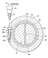
- Sectional drawing along line II-II of FIG. The block diagram which shows the work gripping start point detection device in the hydraulic clamp device which concerns on Embodiment 1.
- Embodiment 1 of the present invention will be described with reference to FIGS. 1 and 2.
- the hydraulic clamp device 10 of the first embodiment is a mandrel type and has a main body (first member) 12.
- the main body 12 has a first axial portion 14, a flange portion 16, and a second axial portion 18 having a circular cross section (cross section orthogonal to the central axis) on the same axis in order in the axial direction.
- the first axial portion 14 and the second axial portion 18 have the same outer diameter.
- the flange portion 16 has an outer diameter larger than that of the first axial portion 14 and the second axial portion 18, and extends outward in the radial direction with respect to the first axial portion 14 and the second axial portion 18. It is formed.
- a first cylindrical member (second member) 20 having an annular cross-sectional shape forming a wall body having a thin wall structure is fitted on the outer periphery of the first axial portion 14.
- the first tubular member 20 is a cylindrical wall body that defines the working liquid chamber 22 on the inner surface side, and has an outer peripheral surface (clamping surface) 20A and a first axial portion 14 that clamp the cylindrical member to be clamped W1.
- the inner peripheral surface (second peripheral surface) 20B fitted to the outer peripheral surface (first peripheral surface) 14A of the above is provided.
- the first tubular member 20 has one end surface abutted against one end surface of the flange portion 16 and the other end surface abuts on one end surface of the snap ring 24 mounted on the first axial portion 14. , Is fixed to the first axial portion 14 so as not to move in the axial direction.
- the fixing of the first cylindrical member 20 to the outer periphery of the first shaft-shaped portion 14 may be performed by another method such as press fitting or adhesion
- a circumferential groove-shaped recess 26 is formed on the outer peripheral surface 14A of the first axial portion 14.
- the first axial portion 14 and the first tubular member 20 have a cross-sectional shape extending over the entire circumference of the outer peripheral surface 14A of the first axial portion 14 by a recess 26 in a portion that overlaps each other in the radial direction.
- An annular working liquid chamber 22 is defined.
- the first tubular member 20 defines the working liquid chamber 22 on the inner surface side and the clamp surface (outer peripheral surface 20A) on the outer surface side.
- the first cylindrical member 20 may be liquidtightly joined to the first shaft-shaped portion 14 by brazing or the like. In this case, the O-ring 28 may be omitted.
- a second cylindrical member 30 having an annular cross-sectional shape forming a thin-walled wall is fitted on the outer periphery of the second axial portion 18.
- the second tubular member 30 is a cylindrical wall body that defines the pressure chamber 32 on the inner surface side, and includes an outer peripheral surface 30A and an inner peripheral surface 30B that fits into the outer peripheral surface 18A of the second axial portion 18.
- the second tubular member 30 has one end face abutted against the other end face of the flange portion 16 and the other end face abuts against one end face of the snap ring 34 mounted on the second axial portion 18. , Is fixed to the second axial portion 18 so as not to move in the axial direction.
- a circumferential groove-shaped recess 36 is formed on the outer peripheral surface 18A of the second shaft-shaped portion 18.
- the second axial portion 18 and the second tubular member 30 have a cross-sectional shape extending over the entire circumference of the outer peripheral surface 18A of the second axial portion 18 by a recess 36 in a portion that overlaps each other in the radial direction.
- An annular pressure chamber 32 is defined.
- the second axial portion 18 and the second tubular member 30 cooperate with each other to form a pressure vessel 40 having a closed structure that defines the pressure chamber 32. That is, the pressure vessel 40 defines the pressure chamber 32 by the second shaft-shaped portion 18 and the second tubular member 30.
- the pressure vessel 40 is integrally provided on the main body 12, and a part thereof is composed of the second shaft-shaped portion 18.
- the second tubular member 30 has a larger wall thickness than the first tubular member 20, and the radial elastic modulus of the second tubular member 30 is the portion where the first tubular member 20 defines the working liquid chamber 22. Higher than the radial modulus.
- O-rings 38 for ensuring the liquidtightness of the pressure chamber 32 are mounted on both sides of the pressure chamber 32 in the axial direction.
- the second cylindrical member 30 may be liquidtightly joined to the second shaft-shaped portion 18 by brazing or the like. In this case, the O-ring 38 may be omitted.
- the main body 12 includes internal passages 42, 44 and 46 that communicate the working liquid chamber 22 and the pressure chamber 32 with each other.
- the internal passage 42 extends in the axial direction at the center of the main body 12, and both ends thereof are closed by the steel balls 48. Each steel ball 48 is pressed against the tapered surface around the internal passage 42 by the screwing of the set screw 50 screw-engaged with the main body 12, so that the end portion of the internal passage 42 is closed in a liquid-tight manner.
- the internal passage 44 extends in the radial direction and connects the internal passage 42 and the working liquid chamber 22 in communication with each other.
- the internal passage 46 extends in the radial direction and connects the internal passage 42 and the pressure chamber 32 in communication with each other.
- the hydraulic fluid chamber 22, the pressure chamber 32, and the internal passages 42, 44, and 46 are filled, sealed, or sealed with hydraulic oil, which is a hydraulic fluid. That is, the hydraulic fluid chamber 22, the pressure chamber 32, and the internal passages 42, 44, and 46 are filled with hydraulic oil.
- One of the sealing portions by the steel ball 48 includes a piston structure portion for adjusting the amount of hydraulic oil and the initial pressure in the hydraulic fluid chamber 22, the pressure chamber 32 and the internal passages 42, 44 and 46. May be good.
- the sealed portion of the piston structure slides when the amount of hydraulic oil and the initial pressure are adjusted, but it does not slide when the clamped member W1 is clamped or unclamped, so that the clamped member W1 is unclamped. It does not cause problems such as improper operation.
- a diameter reduction member 52 is engaged with the outer circumference of the second tubular member 30 so as to be able to reduce the diameter.
- the diameter-reducing member 52 is composed of a C ring having an opening (discontinuous portion) 52A, and the opening 52A is deformed by reducing the diameter as seen in FIG. 2 in the vertical direction. ..
- a bolt through hole 52B is formed at one end of the diameter reduction member 52 on the opening 52A side.
- a screw hole 52C is formed at the other end of the reduced diameter member 52 on the opening 52A side.
- An actuating bolt 54 is inserted into the bolt through hole 52B. The actuating bolt 54 reduces the diameter-reducing member 52 by reducing the vertical distance between the openings 52A by screwing. Due to the reduced diameter deformation of the reduced diameter member 52, the second tubular member 30 is reduced in diameter under elastic deformation.
- the diameter-reducing member 52 engages with the outer periphery of the second tubular member 30 so as to be able to reduce the diameter, and the second tubular member 30 is deformed by the diameter reduction.
- the diameter-reducing member 52 and the operating bolt 54 constitute an elastic deformation applying device 56 that deforms the second tubular member 30 in diameter.
- the volume of the pressure chamber 32 decreases, and the pressure of the hydraulic oil in the pressure chamber 32 increases accordingly.
- the pressure increase of the hydraulic oil in the pressure chamber 32 propagates to the hydraulic fluid chamber 22 through the internal passages 42, 44 and 46, and the pressure of the hydraulic oil in the hydraulic fluid chamber 22 rises.
- the pressure increase of the hydraulic oil in the hydraulic fluid chamber 22 causes the first tubular member 20 to expand its diameter outward in the radial direction under elastic deformation.
- the outer peripheral surface 20A of the first tubular member 20 comes into contact with the inner peripheral surface of the central hole A of the clamped member (work) W1 and is pressed against the inner peripheral surface to clamp the clamped member W1.
- the clamped member W1 has a central hole A that fits on the outer periphery of the first tubular member 20, and the first tubular shape is formed on the inner peripheral surface of the central hole A due to the enlarged diameter deformation of the first tubular member 20.
- the elastic modulus in the radial direction of the second tubular member 30 is set to the working liquid chamber of the first tubular member 20.
- the second tubular member 30 is surely restored to the original state with a higher repulsive force than the first tubular member 20, and the first tubular member 30 is restored. 20 is surely restored to the original state. That is, the reduction deformation of the second tubular member 30 is surely and smoothly performed. As a result, the depressurization of the hydraulic oil in the hydraulic fluid chamber 22 is surely and smoothly performed, and the unclamping of the clamped member W1 is smoothly and surely performed.
- the hydraulic clamping device 10 of the present embodiment pressurizes the hydraulic oil in the hydraulic fluid chamber 22 by elastic deformation of the second tubular member 30 of the pressure vessel 40, the pressurizing portion of the hydraulic oil is like a piston.
- the sliding part disappears. That is, since the hydraulic clamp device 10 is pistonless and does not require a piston, there is no sealing portion of the sliding portion of the piston, and a problem caused by the sealing portion does not occur. Further, the balance between the sliding resistance of the seal portion and the elastic force of the thin-walled tubular portion does not cause a problem that the thin-walled tubular portion is prevented from being restored to the original state, and the clamped member W1 can be used. Unclamping is done smoothly.
- the pressure vessel 40 since a part of the pressure vessel 40 is composed of the main body 12, the pressure vessel 40 is simply configured and the communication between the working liquid chamber 22 and the pressure chamber 32 requires an external pipe. It is surely done without.
- the radial elastic modulus of the second tubular member 30 is higher than the radial elastic modulus of the portion where the first tubular member 20 defines the working liquid chamber 22, so that the first tubular member constituting the clamp portion is formed.
- the wall thickness of 20 can be reduced, and as a result, the merit of increasing the amount of diameter expansion of the clamped member W1 and the first tubular member 20 at low pressure can be obtained.
- a pressure sensor 60 which is a pressure detection device, is attached to the flange portion 16.
- the pressure sensor 60 applies the pressure of the hydraulic oil in the hydraulic fluid chamber 22 and the pressure chamber 32 by the internal passage 62 formed in the main body 12, and measures the pressure of the hydraulic oil.
- the pressure of the hydraulic oil in the hydraulic fluid chamber 22 and the pressure of the hydraulic oil in the pressure chamber 32 are the same pressure.
- the pressure sensor 60 is of a wireless communication type, and transmits measurement value data to a wireless reader 64 arranged in the vicinity of the hydraulic clamp device 10.
- the working bolt 54 is screwed by an electric tool 72 that is rotationally driven by an electric motor 70.
- a rotation angle sensor 74 that measures the rotation angle (rotation amount) of the operating bolt 54 by the tool 72 based on the rotation angle of the motor is connected to the electric motor 70.
- the work gripping start point detecting device has an electronically controlled arithmetic processing unit 76 including a microcomputer.
- the arithmetic processing device 76 inputs a signal (measurement data) indicating the pressure of the hydraulic oil in the working liquid chamber 22 from the pressure sensor 60 of the hydraulic clamping device 10, and the rotation amount of the working bolt 54 from the rotation angle sensor 74, in other words.
- a signal (measurement data) indicating the amount of screwing of the working bolt 54 is input, and the working liquid chamber 22 with respect to the amount of rotation of the working bolt 54, that is, the driving amount of the elastic deformation imparting device 56, is driven by the rotation of the electric motor 70.
- the work gripping start point is detected based on the pressure change of the hydraulic oil.
- the work gripping start point referred to here is the amount of rotation of the working bolt 54 and the working liquid chamber 22 at the time when the outer peripheral surface 20A of the first tubular member 20 starts abutting against the inner peripheral surface of the clamped member W1. Specified by hydraulic oil pressure.
- the detection of the work gripping start point by the arithmetic processing device 76 for detecting the work gripping start point is based on the pressure change of the hydraulic oil in the hydraulic fluid chamber 22 with respect to the rotation amount of the working bolt 54, and the first tubular member 20 is detected.
- the time when the outer peripheral surface 20A of the outer peripheral surface 20A starts to contact the inner peripheral surface of the clamped member W1 the rotation amount of the working bolt 54 and the pressure of the hydraulic oil in the working liquid chamber 22 at that time are detected. be.
- the detection result of the work gripping start point is displayed on the monitor 78 connected to the arithmetic processing unit 76.
- the detection of the work gripping start point by the arithmetic processing unit 76 is performed by any one of the embodiments (A) to (C) or a combination thereof.
- the work gripping start point is a time point at which the pressure increase rate of the hydraulic oil in the hydraulic fluid chamber 22 with respect to the rotation amount of the hydraulic bolt 54 changes with the clamped member W1 attached to the hydraulic clamping device 10.
- Equation 1 and (Equation 2) are proportional constants, and m ⁇ n.
- the proportionality constants m and n correspond to the slopes of the straight lines according to the straight line data of the sections a and b of the graph shown in FIG.
- the solution of the simultaneous equations according to (Equation 1) and (Equation 2) is the intersection C of two straight lines. The intersection C of the two straight lines corresponds to the work gripping start point.
- the spiraling section of the operating bolt 54 in which the outer peripheral surface 20A of the first tubular member 20 does not abut against the inner peripheral surface of the clamped member W1 and the outer peripheral surface 20A of the first tubular member 20 are inside the clamped member W1.
- the estimation of the threading section of the actuating bolt 54 that abuts on the peripheral surface can be estimated in consideration of the tolerance.
- the spiraling section of the operating bolt 54 in which the outer peripheral surface 20A of the first tubular member 20 does not abut against the inner peripheral surface of the clamped member W1 is the outer peripheral surface 20A of the first tubular member 20 from the initial position.
- the section from the position to the position where the outer diameter of the outer peripheral surface 20A is the maximum allowable value.
- the rotation amount of the working bolt 54 and the hydraulic oil of the working liquid chamber 22 in the state where the clamped member W1 is not attached to the hydraulic clamping device 10 and in the state where the clamped member W1 is attached are respectively. Since the section having a large relationship with the pressure of is large, it can be expected that the detection accuracy of the work gripping start point is improved as compared with the embodiment (B).
- the work gripping method according to the present embodiment is carried out in the following manner after the work gripping start point detection work described above.
- the diameter reduction member 52 is returned to the initial position, and the clamped member W1 is placed in the hydraulic clamping device 10.
- the pressure of the hydraulic oil in the hydraulic fluid chamber 22 at the work gripping start point is the work required for the pressure of the hydraulic oil in the hydraulic fluid chamber 22 at the work gripping start point by the screwing of the working bolt 54 by the tool 72.
- the pressure of the hydraulic oil is increased under the supervision of a monitor display or the like until the gripping force reaches the value obtained by adding the necessary pressure.
- the hydraulic clamp device 10 for which the setup has been completed is attached to a chuck device or the like of a machine tool while holding the clamped member W1.
- the gripping force of the clamped member W1 is set based on the pressure of the hydraulic oil in the hydraulic fluid chamber 22 at the work gripping start point detected by the work gripping start point detection method described above. do. Even if the gripping force of the member to be clamped W1 is set based on the driving amount of the elastic deformation applying device (rotation amount of the working bolt 54) instead of the pressure of the hydraulic oil in the working liquid chamber 22 at the work gripping start point. good.
- the clamped member W1 can be accurately gripped with a required gripping force.
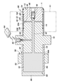
- the hydraulic clamp device 80 is a mandrel type.
- the hydraulic clamp device 80 has a cup-shaped member 82 joined to the second shaft-shaped portion 18 by brazing or the like.
- the cup-shaped member 82 has a cylindrical portion 84 having a circular cross-sectional shape and an end wall 86 that closes an end portion of the tubular portion 84 opposite to the second axial portion 18, and the second axial portion 18 and the tubular portion 18. Together they define the pressure chamber 32.
- the pressure vessel 40 includes the end portion of the second shaft-shaped portion 18 and the cup-shaped member 82, and the pressure chamber 32 is defined by the end portion of the second shaft-shaped portion 18 and the cup-shaped member 82.
- the pressure chamber 32 communicates with the working liquid chamber 22 by internal passages 42 and 44.
- An elastic deformation applying device 56 using a diameter reducing member 52 and an operating bolt 54 is mounted on the outer peripheral surface 84A of the tubular portion 84.
- the elastic deformation imparting device 56 deforms the tubular portion 84 in a reduced diameter (elastic deformation) as in the first embodiment.
- the volume of the pressure chamber 32 decreases and the pressure rises in the hydraulic oil of the pressure chamber 32 accordingly, as in the first embodiment.
- the pressure increase of the hydraulic oil in the pressure chamber 32 propagates to the hydraulic fluid chamber 22 through the internal passages 42 and 44, and the pressure of the hydraulic oil in the hydraulic fluid chamber 22 rises.
- the first tubular member 20 is radially expanded and deformed, and the clamped member W1 is clamped.
- the hydraulic clamp device 80 of the present embodiment also pressurizes the hydraulic oil in the hydraulic fluid chamber 22 by elastic deformation of the tubular portion 84 of the pressure vessel 40, it slides like a piston on the pressurized portion to be pressurized by the hydraulic oil. The part no longer exists. That is, since the hydraulic clamp device 80 is pistonless, there is no sealing portion of the sliding portion of the piston, and a problem caused by the sealing portion does not occur. Further, the balance between the sliding resistance of the seal portion and the elastic force of the thin-walled tubular portion does not cause a problem that the thin-walled tubular portion is prevented from being restored to the original state, and the clamped member W1 can be used. Unclamping is done smoothly.
- the radial elastic modulus of the tubular portion 84 is higher than the radial elastic modulus of the portion where the first tubular member 20 defines the working liquid chamber 22 for reliable restoration of the tubular portion 84.
- the radial elastic modulus of the tubular portion 84 is higher than the radial elastic modulus of the portion where the first tubular member 20 defines the working liquid chamber 22, so that the first tubular member 20 constituting the clamp portion
- the wall thickness can be reduced, and as a result, the merit of increasing the diameter expansion amount of the clamped member W1 and the first tubular member 20 at low pressure can be obtained.
- the above-mentioned is performed based on the measurement of the hydraulic pressure of the working liquid chamber 22 and the rotation amount of the working bolt 54 (see FIG. 1) (driving amount of the elastic deformation imparting device 56) by the pressure sensor 60.
- the work gripping start point can be detected and the work can be gripped by the same method as the work gripping start point detection method and the work gripping method in the hydraulic clamping device 10.
- the gripping force of the member to be clamped W1 is determined based on the pressure of the hydraulic oil in the hydraulic fluid chamber 22 at the work gripping start point detected by the work gripping start point detection method or the rotation amount of the working bolt 54. Can be set.
- the hydraulic clamp device 90 is a mandrel type.
- the hydraulic clamp device 90 has a cup-shaped member 92 joined to the second shaft-shaped portion 18 by brazing or the like.
- the cup-shaped member 92 has a cylindrical portion 94 having a circular cross-sectional shape and an end wall 96 that closes an end portion of the tubular portion 94 opposite to the second axial portion 18, with the second axial portion 18. Together they define the pressure chamber 32.
- the pressure vessel 40 includes the end portion of the second shaft-shaped portion 18 and the cup-shaped member 92, and the pressure chamber 32 is defined by the end portion of the second shaft-shaped portion 18 and the cup-shaped member 92.
- the pressure chamber 32 communicates with the working liquid chamber 22 by internal passages 42 and 44.
- the tubular portion 94 has a tapered outer peripheral surface 94B formed over a predetermined axial length at an intermediate portion in the axial direction of the outer peripheral surface 94A.
- the tapered outer peripheral surface 94B has a tapered shape in which the outer diameter increases toward the end of the second axial portion 18 from the side of the end wall 96.
- the outer peripheral surface 94A is a straight outer peripheral surface whose outer diameter does not change except for the tapered outer peripheral surface 94B.
- a cup-shaped outer fitting member 98 constituting the elastic deformation imparting device is provided on the outside of the tubular portion 94.
- the outer fitting member 98 has a circular cross-sectional shape with a straight inner peripheral surface 100A that is slidably fitted to the outer peripheral surface 94A of the tubular portion 94 in the axial direction, and is opposite to the cylindrical portion 100 and the cup-shaped member 92. Has an end wall 102 that closes the end of the.
- the inner peripheral surface 100A is in sliding contact with the tapered outer peripheral surface 94B due to the axial displacement to the right (the side of the cup-shaped member 92) with respect to the cup-shaped member 92, and the outer peripheral surface is tapered.
- the tubular portion 94 is deformed in diameter.
- the compression coil spring 103 that urges the outer fitting member 98 to the left with respect to the cup-shaped member 92 in the figure.
- the compression coil spring 103 can be replaced with a disc spring or the like.
- a linear actuator 104 of an electric type, a fluid pressure type, or the like is arranged outside the outer fitting member 98.
- the linear actuator 104 is an elastic deformation imparting device, has a push rod 106 that can be displaced in the axial direction as an axial movement member, and the outer fitting member 98 is displaced against the compression coil spring 103 by the push rod 106. Move to the right in the axial direction.
- the linear actuator 104 is provided with a linear scale 108 that measures the amount of movement of the push rod 106 in the axial direction.
- the tubular portion 94 is moved in the axial direction to the right of the outer fitting member 98 by the linear actuator 104, so that the tubular portion 94 is in the axial direction of the inner peripheral surface 100A of the outer fitting member 98 with respect to the tapered outer peripheral surface 94B of the cup-shaped member 92. Due to sliding, diameter reduction deformation (elastic deformation) occurs.
- the volume of the pressure chamber 32 decreases and the pressure of the hydraulic oil in the pressure chamber 32 increases accordingly, as in the first embodiment.
- the pressure increase of the hydraulic oil in the pressure chamber 32 propagates to the hydraulic fluid chamber 22 through the internal passages 42 and 44, and the pressure of the hydraulic oil in the hydraulic fluid chamber 22 rises.
- the first tubular member 20 is radially expanded and deformed, and the clamped member W1 is clamped.
- the hydraulic clamp device 90 of the present embodiment also pressurizes the hydraulic oil in the hydraulic fluid chamber 22 by elastic deformation of the tubular portion 94 of the pressure vessel 40, it slides like a piston on the pressurized portion to be pressurized by the hydraulic oil. The part no longer exists. That is, since the hydraulic clamp device 90 is pistonless, there is no sealing portion of the sliding portion of the piston, and a problem caused by the sealing portion does not occur. Further, the balance between the sliding resistance of the seal portion and the elastic force of the thin-walled tubular portion does not cause a problem that the thin-walled tubular portion is prevented from being restored to the original state, and the clamped member W1 can be used. Unclamping is done smoothly.
- the outer fitting member 98 is urged in the return direction by the spring force of the compression coil spring 103, the tubular portion 94 by the outer fitting member 98 is surely and smoothly released from the reduced diameter deformation at the time of unclamping. It is done in. As a result, the depressurization of the hydraulic oil in the hydraulic fluid chamber 22 is surely and smoothly performed, and the unclamping of the clamped member W1 is surely and smoothly performed.
- the radial elastic modulus of the tubular portion 94 is higher than the radial elastic modulus of the portion where the first tubular member 20 defines the working liquid chamber 22 for reliable restoration of the tubular portion 94. Also by this, at the time of unclamping, the reduced diameter deformation of the cylindrical portion 94 is surely and smoothly performed. As a result, the depressurization of the hydraulic oil in the hydraulic fluid chamber 22 is surely and smoothly performed, and the unclamping of the clamped member W1 is smoothly and surely performed under the reduced diameter deformation of the first tubular member 20.
- the radial elastic modulus of the tubular portion 94 is higher than the radial elastic modulus of the portion where the first tubular member 20 defines the working liquid chamber 22, so that the first tubular member 20 constituting the clamp portion
- the wall thickness can be reduced, and as a result, the merit of increasing the diameter expansion amount of the clamped member W1 and the first tubular member 20 at low pressure can be obtained.
- the above-mentioned is performed based on the measurement of the hydraulic pressure of the working liquid chamber 22 by the pressure sensor 60 and the axial movement amount (driving amount of the elastic deformation imparting device) of the push rod 106 by the linear scale 108.
- the work gripping start point can be detected and the work can be gripped by the same method as the work gripping start point detection method and the work gripping method in the hydraulic clamping device 10.
- the amount of rotation on the horizontal axis in FIG. 4 is replaced with the amount of movement in the axial direction, and the arithmetic processing unit 76 in FIG. 3 uses the measured value of the amount of movement in the axial direction of the push rod 106 instead of the measured value of the amount of rotation. Should be entered.
- the clamped member W1 is gripped based on the pressure of the hydraulic oil in the working liquid chamber 22 at the work gripping start point detected by the work gripping start point detection method or the axial movement amount of the push rod 106.
- the force can be set.
- FIG. 7 the portion corresponding to FIG. 1 is designated by the same reference numeral as that shown in FIG. 1, and the description thereof will be omitted.
- the hydraulic clamp device 110 is a mandrel type.
- the hydraulic clamp device 110 has a cup-shaped member 112 joined to the second shaft-shaped portion 18 by brazing or the like.
- the cup-shaped member 112 has a cylindrical portion 114 having a circular cross-sectional shape and an end wall 116 that closes an end portion of the tubular portion 114 opposite to the second axial portion 18, with the second axial portion 18. Together they define the pressure chamber 32.
- the pressure vessel 40 includes an end portion of the second shaft-shaped portion 18 and a cup-shaped member 112, and the pressure chamber 32 is defined by the end portion of the second shaft-shaped portion 18 and the cup-shaped member 112.
- the pressure chamber 32 communicates with the working liquid chamber 22 by internal passages 42 and 44.
- the end wall 116 has a base portion 116A provided in the central portion and an annular thin-walled portion 116B extending between the base portion 116A and the tubular portion 114.
- the thin-walled portion 116B has a lower flexural rigidity than the base portion 116A, and is easily elastically deformed in the axial direction. By elastically deforming the thin portion 116B to the right in the figure in the axial direction, the volume of the pressure chamber 32 is reduced and the pressure of the hydraulic oil in the pressure chamber 32 is increased.
- the pressure increase of the hydraulic oil in the pressure chamber 32 propagates to the hydraulic fluid chamber 22 through the internal passages 42 and 44, and the pressure of the hydraulic oil in the hydraulic fluid chamber 22 rises.
- the first tubular member 20 is radially expanded and deformed, and the clamped member W1 is clamped.
- a compression coil spring 128 is provided between the base portion 116A and the second axial portion 18 to urge the end wall 116 to the left with respect to the second axial portion 18 in the figure.
- the compression coil spring 128 can be replaced with a disc spring or the like.
- a cup-shaped base 118 is attached to the cup-shaped member 112.
- the base 118 has a circular cross-sectional shape of the tubular portion 120 joined to the outer end of the tubular portion 114 of the cup-shaped member 112 by brazing or the like, and the cylindrical portion 120 on the opposite side of the cup-shaped member 112. It has an end wall 122 that closes the end.
- a screw hole 124 is formed through the end wall 122 in the axial direction.
- An actuating bolt 126 that can be displaced in the axial direction is screw-engaged in the screw hole 124 as an axially moving member of an elastic deformation applying device that elastically deforms the thin portion 116B of the end wall 116 in the axial direction.
- the actuating bolt 126 abuts on the base 116A of the end wall 116 and presses the base 116A by screwing to elastically deform the thin portion 116B to the right in the drawing in the axial direction.
- the actuating bolt 126 is rotationally driven by an electric tool (not shown) similar to the electric tool 72 of the first embodiment, and is screwed to the right in the figure.
- the hydraulic clamp device 110 of the present embodiment pressurizes the hydraulic oil in the hydraulic fluid chamber 22 by elastic deformation of the thin-walled portion 116B of the pressure vessel 40, a sliding portion such as a piston is applied to the pressurized portion to be pressurized by the hydraulic oil. Does not exist. That is, since the hydraulic clamp device 110 is pistonless, there is no sealing portion of the sliding portion of the piston, and a problem caused by the sealing portion does not occur. Further, the balance between the sliding resistance of the seal portion and the elastic force of the thin-walled tubular portion does not cause a problem that the thin-walled tubular portion is prevented from being restored to the original state, and the clamped member W1 can be used. Unclamping is done smoothly.
- the elastic deformation of the thin wall portion 116B is released by the spring force of the compression coil spring 128, the elastic deformation of the thin wall portion 116B in the axial direction is surely and smoothly released at the time of unclamping. Will be. As a result, the depressurization of the hydraulic oil in the hydraulic fluid chamber 22 is surely and smoothly performed, and the unclamping of the clamped member W1 is surely and smoothly performed.
- the elastic modulus in the axial direction of the end wall 116 including the thin-walled portion 116B is higher than the elastic modulus in the radial direction of the portion where the first tubular member 20 defines the working liquid chamber 22. Also by this, at the time of unclamping, the elastic deformation in the axial direction of the thin-walled portion 116B is surely and smoothly released. As a result, the depressurization of the hydraulic oil in the hydraulic fluid chamber 22 is surely and smoothly performed, and the unclamping of the clamped member W1 is smoothly and surely performed under the reduced diameter deformation of the first tubular member 20.
- the elastic modulus in the axial direction of the end wall 116 including the thin-walled portion 116B is higher than the elastic modulus in the radial direction of the portion where the first tubular member 20 defines the working liquid chamber 22, so that the first cylinder constituting the clamp portion is formed.
- the wall thickness of the shaped member 20 can be reduced, and as a result, there is an advantage that the clamp of the clamped member W1 at a low pressure and the diameter expansion amount of the first tubular member 20 are increased.
- the hydraulic clamp device 10 In the hydraulic clamp device 110, the hydraulic clamp device 10 described above measures the hydraulic pressure of the working liquid chamber 22 and the rotation amount of the working bolt 126 (driving amount of the elastic deformation imparting device) by the pressure sensor 60.
- the work gripping start point can be detected and the work can be gripped by the same method as the work gripping start point detection method and the work gripping method.
- the gripping force of the member W1 to be clamped is determined based on the pressure of the hydraulic oil in the working liquid chamber 22 at the working gripping start point detected by the work gripping start point detecting method or the rotation amount of the working bolt 126. Can be set.
- the hydraulic clamp device 130 is a chuck type and has a main body (first member) 132.
- the main body 132 has a first axial portion 134, a flange portion 136, and a second axial portion 138 having a circular cross-sectional shape on the same axis in order in the axial direction.
- first axial portion 134 there is a circular cross-sectional shaped bottomed hole 139 opened on the right end surface in the figure and a circumference opened on the inner peripheral surface 139A (first peripheral surface) of the bottomed hole 139.
- a groove-shaped recess 144 is formed.
- a tubular member (second member) 140 having an annular cross-sectional shape forming a wall body having a thin wall structure is fitted in the bottomed hole 139.
- the tubular member 140 is joined to the first axial portion 134 by brazing or the like, and has a recess 144 on the outer peripheral surface 140A (second peripheral surface) side over the entire circumference of the inner peripheral surface 139A of the bottomed hole 139.
- the extending cross-sectional shape defines the annular working liquid chamber 142.
- the tubular member 140 defines a clamp surface for clamping the round bar-shaped member to be clamped (work) W2 by the inner peripheral surface 140B.
- the tubular member 140 defines the working liquid chamber 142 on the outer peripheral side and the clamp surface (inner peripheral surface 140B) on the inner peripheral side.
- the second axial portion 138 includes a recess 146 opened in the central portion of the outer end.
- An end wall member 148 including an end wall that closes the opening of the recess 146 is joined to the outer end (end) of the second axial portion 138 by brazing or the like.
- the end wall member 148 cooperates with the second axial portion 138 to define the pressure vessel 149.
- the pressure vessel 149 includes the second shaft-shaped portion 138 and the end wall member 148, and the pressure chamber 150 is defined by the second shaft-shaped portion 138 and the end wall member 148.
- the pressure chamber 150 communicates with the working liquid chamber 142 by internal passages 151, 152, 154 and 156 formed in the main body 132.
- the hydraulic fluid chamber 142, the pressure chamber 150, and the internal passages 151, 152, 154, and 156 are filled with hydraulic oil as the hydraulic fluid.
- the end wall member 148 has a pedestal portion 148A provided in the central portion and an annular thin-walled portion 148B extending between the pedestal portion 148A and the second axial portion 138.
- the thin-walled portion 148B has a lower bending rigidity than the base portion 148A, and is easily elastically deformed in the axial direction. By elastically deforming the thin portion 148B to the right in the figure in the axial direction, the volume of the pressure chamber 150 is reduced and the pressure of the hydraulic oil in the pressure chamber 150 is increased.
- the pressure increase of the hydraulic oil in the pressure chamber 150 propagates to the hydraulic fluid chamber 22 through the internal passages 151, 152, 154 and 156, and the pressure rises in the hydraulic oil in the hydraulic fluid chamber 22.
- the first tubular member 20 is radially inwardly deformed to clamp the member to be clamped W2.
- a plurality of disc springs 162 for urging the end wall member 148 to the left with respect to the second axial portion 138 are provided.
- the disc spring 162 can be replaced with a compression coil spring or the like.
- a linear actuator 158 of an electric type, a fluid pressure type, etc. is arranged outside the end wall member 148.
- the linear actuator 158 is an elastic deformation imparting device, has a push rod 160 that can be displaced in the axial direction as an axial movement member, and the push rod 160 resists the base portion 148A of the end wall member 148 against the disc spring 162. Press to the right in the figure to elastically deform the thin portion 148B to the right in the figure in the axial direction.
- the linear actuator 158 is provided with a linear scale 166 that measures the amount of movement of the push rod 160 in the axial direction.
- the hydraulic clamp device 130 of the present embodiment pressurizes the hydraulic oil of the hydraulic fluid chamber 142 by elastic deformation of the thin-walled portion 148B of the pressure vessel 149, a sliding portion such as a piston is applied to the pressurized portion of the hydraulic oil. Does not exist. That is, since the hydraulic clamp device 130 is pistonless, there is no sealing portion of the sliding portion of the piston, and a problem caused by the sealing portion does not occur. Further, the balance between the sliding resistance of the seal portion and the elastic force of the thin-walled tubular portion does not cause a problem that the thin-walled tubular portion is prevented from being restored to the original state, and the clamped member W2 Unclamping is done smoothly.
- the elastic deformation of the thin-walled portion 148B is urged by the spring force of the disc spring 162 in the direction of releasing the elastic deformation of the thin-walled portion 148B, the elastic deformation of the thin-walled portion 148B in the axial direction is surely and smoothly performed at the time of unclamping.
- the depressurization of the hydraulic oil in the hydraulic fluid chamber 142 is reliably and smoothly performed, and the unclamping of the clamped member W2 is reliably and smoothly performed under the expanded diameter deformation of the tubular member 140.
- the elastic modulus in the axial direction of the end wall member 148 including the thin-walled portion 148B is higher than the elastic modulus in the radial direction of the portion where the tubular member 140 defines the working liquid chamber 142. Also by this, at the time of unclamping, the elastic deformation of the thin portion 148B in the axial direction is surely and smoothly performed. As a result, the depressurization of the hydraulic oil in the hydraulic fluid chamber 142 is reliably and smoothly performed, and the clamped member W2 is smoothly and reliably unclamped under the expanded diameter deformation of the tubular member 140.
- the elastic modulus in the axial direction of the end wall member 148 including the thin-walled portion 148B is higher than the elastic modulus in the radial direction of the portion where the tubular member 140 defines the working liquid chamber 142, so that the tubular member 140 constituting the clamp portion is formed.
- the clamp of the member to be clamped W2 at a low pressure and the merit of increasing the diameter reduction amount of the tubular member 140 can be obtained.
- a pressure sensor (pressure measuring device) 60 is attached to the second shaft-shaped portion 138.
- the pressure sensor 60 applies the pressure of the hydraulic oil in the hydraulic fluid chamber 142 and the pressure chamber 150 by the internal passage 164 formed in the main body 12, and measures the pressure of the hydraulic oil.
- the pressure of the hydraulic oil in the hydraulic fluid chamber 142 and the pressure of the hydraulic oil in the pressure chamber 150 are the same pressure.
- the pressure sensor 60 is of a wireless communication type, and transmits measurement value data to a wireless reader 64 arranged in the vicinity of the hydraulic clamp device 130.
- the above-mentioned is performed based on the measurement of the hydraulic pressure of the working liquid chamber 142 by the pressure sensor 60 and the axial movement amount (driving amount of the elastic deformation imparting device) of the push rod 160 by the linear scale 108.
- the work gripping start point can be detected and the work can be gripped by the same method as the work gripping start point detection method and the work gripping method in the hydraulic clamping device 10.
- the amount of rotation on the horizontal axis in FIG. 4 is replaced with the amount of movement in the axial direction, and the arithmetic processing unit 76 in FIG. 3 is used to measure the amount of movement in the axial direction of the push rod 160 instead of the measured value of the amount of rotation. Should be entered.
- the clamped member W1 is gripped based on the pressure of the hydraulic oil in the working liquid chamber 142 at the work gripping start point detected by the work gripping start point detection method or the axial movement amount of the push rod 160. You can set the force.
- the structure of the pressure vessel 40 and the elastic deformation imparting device 56 of the mandrel type hydraulic clamp devices 10, 80, 90 and 110 of the first to fourth embodiments are the chuck type hydraulic clamp device 130 of the fifth embodiment.
- the structure of the pressure vessel of the chuck type hydraulic clamp device 130 of the fifth embodiment and the elastic deformation imparting device and the like can be applied to the mandrel type hydraulic clamp devices 10, 80, 90 and 110 of the first to fourth embodiments.
- the recesses 26 and 144 may be provided in the first cylindrical member 20 and the tubular member 140.
- hydraulic oil is used as the hydraulic liquid has been described, but water or a gel-like substance can also be used in addition to this.
- the elastic modulus in the radial direction of the second tubular member 30, the tubular portions 84, 94 or the elastic modulus in the axial direction of the end wall 122 and the end wall member 148 is such that the first tubular member 20 defines the working liquid chamber 22.
- the portion or the tubular member 140 may be equal to the radial elastic modulus of the portion defining the working liquid chamber 142.
- the pressure sensor 60 is not limited to the wireless communication type, and may be a wired type that transmits a signal via a connector or the like.
- Hydraulic clamp device 12 Main body (first member) 14: First axial portion 14A: Outer peripheral surface (first peripheral surface) 16: Flange portion 18: Second axial portion 18A: Outer peripheral surface 20: First tubular member (second member) 20A: Outer peripheral surface 20B: Inner peripheral surface (second peripheral surface) 22: Working liquid chamber 24: Snap ring 26: Recess 28: O ring 30: Second tubular member 30A: Outer peripheral surface 30B: Inner peripheral surface 32: Pressure chamber 34: Snap ring 36: Recess 38: O ring 40: Pressure Container 42: Internal passage 44: Internal passage 46: Internal passage 48: Steel ball 50: Push screw 52: Diameter reduction member 52A: Opening 52B: Bolt through hole 52C: Screw hole 54: Actuating bolt 56: Elastic deformation imparting device 60: Pressure sensor (pressure detector) 62: Internal passage 64: Wireless reader 70: Electric motor 72: Tool 74: Rotation angle sensor 76: Arithmetic processing device 78: Monitor 80: Hydraulic clamp device 82: Cup-shaped
Abstract
[Problem] To provide a hydraulic clamp device that does not need a slidable sealing part in a pressurizing part for pressurizing a working fluid in a working fluid chamber, thereby solving the occurrence of defects related to a sealing part. [Solution] A hydraulic clamp device 10 which has a body 12 provided with an outer peripheral surface 14A and a first cylindrical member 20 provided with an inner peripheral surface 20B overlapping with the outer peripheral surface 14A and in which a portion where the body 12 and the first cylindrical member 20 overlap has a recessed section 26 that defines a working fluid chamber 22, and the pressure of a working fluid sealed in the working fluid chamber 22 causes the first cylindrical member 20 to be elastically deformed to clamp a member W1 to be clamped, the hydraulic clamp device comprising: a pressurizing container 40 that defines a pressurizing chamber 32 communicating with the working fluid chamber 22 and filled with the working fluid and, by being elastically deformed, pressurizes the working fluid in the pressurizing chamber 32; and an elastic deformation-providing device 56 that elastically deforms the pressurizing container 40.
Description
本発明は、機械加工分野、測定分野において使用される被クランプ部材を作動液体に圧力を加えてクランプ(以下、把持とも云う。)する液圧式クランプ装置、液圧式クランプ装置におけるワーク把持開始点検出方法、ワーク把持開始点検出装置及びワーク把持方法に関する。
INDUSTRIAL APPLICABILITY The present invention detects a work gripping start point in a hydraulic clamping device and a hydraulic clamping device that clamp (hereinafter, also referred to as gripping) a member to be clamped used in the machining field and the measuring field by applying pressure to a working liquid. The present invention relates to a method, a work gripping start point detection device, and a work gripping method.
液圧式クランプ装置としては、作動液体室を画定する薄肉筒状部を含む本体と、この本体に設けられ、前記作動液体室に封入された作動液体を加圧する加圧部とを有し、前記薄肉筒状部が前記作動液体室に封入された作動液体に圧力を加えることによって径方向に弾性変形することにより被クランプ部材(以下、ワークとも云う。)をクランプするものが知られている。加圧部は、本体に摺動可能に設けられたピストン及び本体にねじ係合した作動ねじを有し、作動ねじの螺進によってピストンが前進することにより作動液体を加圧するピストン式である(例えば、特許文献1)。
The hydraulic clamp device has a main body including a thin-walled tubular portion that defines a working liquid chamber, and a pressurizing portion that is provided in the main body and pressurizes the working liquid that is sealed in the working liquid chamber. It is known that a thin-walled tubular portion clamps a member to be clamped (hereinafter, also referred to as a work) by elastically deforming in the radial direction by applying pressure to the working liquid enclosed in the working liquid chamber. The pressurizing portion has a piston slidably provided on the main body and a working screw screw-engaged with the main body, and is a piston type that pressurizes the working liquid by advancing the piston by the screwing of the working screw ( For example, Patent Document 1).
ピストン式の加圧部は、作動液体室の液密性を確保するために、つまり、昇圧された作動液体が作動液体室外に漏洩しないために、本体とピストンとの間に高度の液密性を保証するシール部が必要である。
The piston-type pressurizing part has a high degree of liquidtightness between the main body and the piston in order to ensure the liquidtightness of the working liquid chamber, that is, to prevent the boosted working liquid from leaking to the outside of the working liquid chamber. A seal that guarantees is required.
シール部は、本体に対して摺動可能な動的なものであるため、使用過程での摩耗や劣化等によってシール性が低下することを避けられず、メンテナンスが必要である。また、シール部の摺動抵抗と薄肉筒状部の弾発力との兼ね合いにより、薄肉筒状部が元の状態に復元することが阻害される虞があり、被クランプ部材のアンクランプが円滑に行われなくなる不具合を生じる。
Since the seal part is a dynamic one that can slide with respect to the main body, it is inevitable that the sealability will deteriorate due to wear and deterioration during use, and maintenance is required. In addition, the balance between the sliding resistance of the seal portion and the elastic force of the thin-walled cylindrical portion may hinder the restoration of the thin-walled tubular portion to the original state, and the clamped member can be unclamped smoothly. It causes a problem that it is not done.
本発明が解決しようとする課題は、作動液体室の作動液体を昇圧するための加圧部における摺動可能なシール部を不要にし、シール部に起因する不具合の発生を解消した液圧式クランプ装置、及び、その液圧式クランプ装置におけるワーク把持開始点検出方法、ワーク把持開始点検出装置、ワーク把持方法を提供することにある。
The problem to be solved by the present invention is a hydraulic clamp device that eliminates the need for a slidable seal portion in the pressurizing portion for boosting the hydraulic fluid in the hydraulic fluid chamber and eliminates the occurrence of defects caused by the seal portion. , And a method for detecting a work gripping start point, a work gripping start point detecting device, and a work gripping method in the hydraulic clamp device.
(1)かかる課題を解決するために、本発明による一つの実施形態による液圧式クランプ装置は、外周面又は内周面をなす第1の周面を備えた第1の部材と、前記第1の周面に重なり合う内周面又は外周面をなす第2の周面を備えた第2の部材とを有し、前記第1の部材及び前記第2の部材が互いに重なり合う部分に、前記第1の周面及び前記第2の周面の少なくとも一方に設けられた凹部により作動液体室が画定され、前記作動液体室に封入された作動液体の圧力によって前記第2の部材が弾性変形することにより、被クランプ部材をクランプする液圧式クランプ装置であって、前記作動液体室に連通して作動液体を満たされた圧力室を画定し、弾性変形によって前記圧力室の作動液体を昇圧させる圧力容器と、前記圧力容器を弾性変形させる弾性変形付与装置とを有する。
(1) In order to solve such a problem, the hydraulic clamping device according to one embodiment of the present invention includes a first member having a first peripheral surface forming an outer peripheral surface or an inner peripheral surface, and the first member. The first member has a second member having a second peripheral surface forming an inner peripheral surface or an outer peripheral surface that overlaps the peripheral surface of the above, and the first member and the second member overlap each other. A working liquid chamber is defined by a recess provided on at least one of the peripheral surface and the second peripheral surface, and the second member is elastically deformed by the pressure of the working liquid enclosed in the working liquid chamber. A hydraulic clamping device that clamps a member to be clamped, and a pressure vessel that communicates with the working liquid chamber to define a pressure chamber filled with the working liquid and pressurizes the working liquid in the pressure chamber by elastic deformation. The pressure vessel is provided with an elastic deformation imparting device that elastically deforms the pressure vessel.
この構成によれば、ピストンを必要とすることなく、作動液体室の作動液体を昇圧できる。これにより、ピストンを含む加圧部における、摺動することが不可避なシール部が不要になり、シール部に起因する不具合の発生が解消される。
According to this configuration, the working liquid in the working liquid chamber can be boosted without the need for a piston. This eliminates the need for a seal portion that inevitably slides in the pressure portion including the piston, and eliminates the occurrence of problems caused by the seal portion.
(2)上記液圧式クランプ装置は、好ましくは、前記圧力容器は、前記第1の部材に一体的に設けられ、一部を前記第1の部材によって構成されている。
(2) In the hydraulic clamp device, preferably, the pressure vessel is integrally provided with the first member, and a part thereof is composed of the first member.
この構成によれば、圧力容器が簡素に構成される。
According to this configuration, the pressure vessel is simply configured.
(3)上記液圧式クランプ装置は、好ましくは、前記圧力容器は、前記第1の部材の軸状部及び前記軸状部の外周に装着された筒状部材を含み、前記軸状部と前記筒状部材とにより前記圧力室を画定し、前記弾性変形付与装置は、前記筒状部材の外周に縮径可能に係合し、縮径により前記筒状部材を縮径変形させる縮径部材を含み、前記第1の部材は前記作動液体室と前記圧力室とを連通する内部通路を含む請求項1に記載の液圧式クランプ装置。
(3) In the hydraulic clamping device, preferably, the pressure vessel includes a shaft-shaped portion of the first member and a tubular member mounted on the outer periphery of the shaft-shaped portion, and the shaft-shaped portion and the shaft-shaped portion. The pressure vessel is defined by the tubular member, and the elastic deformation imparting device engages with the outer periphery of the tubular member so as to be able to reduce the diameter, and the diameter reduction member deforms the tubular member by the diameter reduction. The hydraulic clamping device according to claim 1, wherein the first member includes an internal passage connecting the working liquid chamber and the pressure vessel.
この構成によれば、圧力容器の筒状部材の縮径変形によって作動液体室の作動液体の昇圧が行われる。また、圧力容器が簡素に構成されると共に作動液体室と圧力室との連通が外部配管を必要とすることなく確実に行われる。
According to this configuration, the working liquid in the working liquid chamber is boosted by the reduced diameter deformation of the tubular member of the pressure vessel. In addition, the pressure vessel is simply constructed, and communication between the working liquid chamber and the pressure chamber is reliably performed without the need for external piping.
(4)上記液圧式クランプ装置は、好ましくは、前記筒状部材は、径方向の弾性係数が、前記第2の部材が前記作動液体室を画定する部分の径方向の弾性係数より高い部分を含んでいる。
(4) In the hydraulic clamping device, preferably, the tubular member has a portion in which the elastic modulus in the radial direction is higher than the elastic modulus in the radial direction of the portion where the second member defines the working liquid chamber. Includes.
この構成によれば、圧力容器の筒状部材の縮径変形の解除が確実且つ円滑に行われる。
According to this configuration, the reduced diameter deformation of the tubular member of the pressure vessel is surely and smoothly performed.
(5)上記液圧式クランプ装置は、好ましくは、前記圧力容器は、前記第1の部材の端部に装着され、筒状部及び前記筒状部の前記第1の部材とは反対側の端部を閉じる端壁を有するカップ状部材を含み、前記第1の部材の端部と前記カップ状部材とにより前記圧力室を画定し、前記弾性変形付与装置は、前記筒状部の外周に縮径可能に係合し、縮径により前記筒状部を縮径変形させる縮径部材を含み、前記第1の部材は前記作動液体室と前記圧力室とを連通する内部通路を含む。
(5) In the hydraulic clamping device, preferably, the pressure vessel is attached to the end portion of the first member, and the tubular portion and the end of the tubular portion opposite to the first member. The pressure vessel is defined by the end portion of the first member and the cup-shaped member, and the elastic deformation imparting device is contracted to the outer periphery of the tubular portion, including a cup-shaped member having an end wall for closing the portion. A diameter-reducing member that engages diametrically and deforms the tubular portion by diameter reduction is included, and the first member includes an internal passage that communicates the working liquid chamber and the pressure vessel.
この構成によれば、筒状部材の縮径変形によって作動液体室の作動液体の昇圧が行われる。また、圧力容器が簡素に構成されると共に作動液体室と圧力室との連通が外部配管を必要とすることなく確実に行われる。
According to this configuration, the working liquid in the working liquid chamber is boosted by the reduced diameter deformation of the tubular member. In addition, the pressure vessel is simply constructed, and communication between the working liquid chamber and the pressure chamber is reliably performed without the need for external piping.
(6)上記液圧式クランプ装置は、好ましくは、前記圧力容器は、前記第1の部材の端部に装着され、少なくとも軸線方向の一部にテーパ状外周面を含む筒状部及び前記筒状部の前記第1の部材とは反対側の端部を閉じる端壁を有するカップ状部材により構成され、前記第1の部材の端部と前記カップ状部材とにより前記圧力室を画定し、前記弾性変形付与装置は、前記テーパ状外周面に軸線方向に摺動可能に嵌合する内周面を具備し、前記カップ状部材に対する軸線方向の変位により前記筒状部を縮径変形させる外嵌合部材を含み、前記第1の部材は前記作動液体室と前記圧力室とを連通する内部通路を含む。
(6) In the hydraulic clamping device, preferably, the pressure vessel is attached to the end portion of the first member, and the tubular portion and the tubular portion including a tapered outer peripheral surface at least in a part in the axial direction. The pressure vessel is defined by a cup-shaped member having an end wall that closes an end portion of the portion opposite to the first member, and the end portion of the first member and the cup-shaped member define the pressure vessel. The elastic deformation imparting device is provided with an inner peripheral surface that is slidably fitted to the tapered outer peripheral surface in the axial direction, and the outer fitting that deforms the tubular portion by reducing the diameter due to the axial displacement with respect to the cup-shaped member. The first member includes an internal passage connecting the working liquid chamber and the pressure vessel.
この構成によれば、筒状部材の縮径変形によって作動液体室の作動液体の昇圧が行われる。また、圧力容器が簡素に構成されると共に作動液体室と圧力室との連通が外部配管を必要とすることなく確実に行われる。
According to this configuration, the working liquid in the working liquid chamber is boosted by the reduced diameter deformation of the tubular member. In addition, the pressure vessel is simply constructed, and communication between the working liquid chamber and the pressure chamber is reliably performed without the need for external piping.
(7)上記液圧式クランプ装置は、好ましくは、前記筒状部は、径方向の弾性係数が、前記第2の部材が前記作動液体室を画定する部分の径方向の弾性係数より高い部分を含んでいる。
(7) In the hydraulic clamping device, preferably, the tubular portion has a portion in which the elastic modulus in the radial direction is higher than the elastic modulus in the radial direction of the portion where the second member defines the working liquid chamber. Includes.
この構成によれば、筒状部の縮径変形の解除が確実且つ円滑に行われる。
According to this configuration, the reduced diameter deformation of the cylindrical portion can be reliably and smoothly released.
(8)上記液圧式クランプ装置は、好ましくは、前記圧力容器は、前記第1の部材の端部に装着され、筒状部及び前記筒状部の前記第1の部材とは反対側の端部を閉じる端壁を有するカップ状部材を含み、前記第1の部材の端部と前記カップ状部材とにより前記圧力室を画定し、前記弾性変形付与装置は、前記カップ状部材に対して軸線方向の変位可能に設けられ、軸線方向の変位により前記端壁を軸線方向に変形させる軸線方向移動部材を含み、前記第1の部材は前記作動液体室と前記圧力室とを連通する内部通路を含む。
(8) In the hydraulic clamping device, preferably, the pressure vessel is attached to the end portion of the first member, and the tubular portion and the end of the tubular portion opposite to the first member. The pressure vessel is defined by the end portion of the first member and the cup-shaped member, and the elastic deformation imparting device includes an axis line with respect to the cup-shaped member. Includes an axially moving member that is displaceable in the direction and deforms the end wall in the axial direction due to axial displacement, the first member having an internal passage connecting the working liquid chamber and the pressure vessel. include.
この構成によれば、端壁の軸線方向の変形によって作動液体室の作動液体の昇圧が行われる。また、圧力容器が簡素に構成されると共に作動液体室と圧力室との連通が外部配管を必要とすることなく確実に行われる。
According to this configuration, the working liquid in the working liquid chamber is boosted by the deformation of the end wall in the axial direction. In addition, the pressure vessel is simply constructed, and communication between the working liquid chamber and the pressure chamber is reliably performed without the need for external piping.
(9)上記液圧式クランプ装置は、前記第1の部材は端部に開口した凹部を含み、前記圧力容器は、前記凹部の開口を閉じる端壁を含んで前記第1の部材の前記端部に装着された端壁部材を含み、前記第1の部材の端部と端壁部材とにより前記圧力室を画定し、前記弾性変形付与装置は、前記端壁部材に対して軸線方向の変位可能に設けられ、軸線方向の変位により前記端壁を軸線方向に変形させる軸線方向移動部材を含み、前記第1の部材は前記作動液体室と前記圧力室とを連通する内部通路を含む。
(9) In the hydraulic clamping device, the first member includes a recess opened at an end, and the pressure vessel includes an end wall that closes the opening of the recess, and the end of the first member. The pressure vessel is defined by the end portion of the first member and the end wall member, and the elastic deformation imparting device can be displaced in the axial direction with respect to the end wall member. The first member includes an internal passage connecting the working liquid chamber and the pressure vessel.
この構成によれば、端壁を軸線方向に変形によって作動液体室の作動液体の昇圧が行われる。また、圧力容器が簡素に構成されると共に作動液体室と圧力室との連通が外部配管を必要とすることなく確実に行われる。
According to this configuration, the working liquid in the working liquid chamber is boosted by deforming the end wall in the axial direction. In addition, the pressure vessel is simply constructed, and communication between the working liquid chamber and the pressure chamber is reliably performed without the need for external piping.
(10)上記液圧式クランプ装置は、好ましくは、前記端壁は、軸線方向の弾性係数が、前記第2の部材が前記作動液体室を画定する部分の径方向の弾性係数より高い部分を含んでいる。
(10) The hydraulic clamping device preferably includes a portion of the end wall whose axial elastic modulus is higher than the radial elastic modulus of the portion where the second member defines the working liquid chamber. I'm out.
この構成によれば、端壁の軸線方向の変形の解除が確実且つ円滑に行われる。
According to this configuration, the deformation of the end wall in the axial direction is surely and smoothly performed.
(11)上記液圧式クランプ装置は、好ましくは、前記第1の部材と前記端壁との間に設けられ、前記端壁の軸線方向の変形を復元する方向に付勢する付勢部材を有する。
(11) The hydraulic clamping device preferably has an urging member provided between the first member and the end wall and urging in a direction for restoring axial deformation of the end wall. ..
この構成によれば、端壁の軸線方向の変形の解除が確実且つ円滑に行われる。
According to this configuration, the deformation of the end wall in the axial direction is surely and smoothly performed.
(12)かかる課題を解決するため、本発明による一つの実施形態による液圧式クランプ装置におけるワーク把持開始点検出方法は、外周面又は内周面をなす第1の周面を備えた第1の部材と、前記第1の周面に重なり合う内周面又は外周面をなす第2の周面を備えた第2の部材とを有し、前記第1の部材及び前記第2の部材が互いに重なり合う部分に、前記第1の周面及び前記第2の周面の少なくとも一方に設けられた凹部により作動液体室が画定され、前記作動液体室に封入された作動液体の圧力によって前記第2の部材が弾性変形することにより、被クランプ部材をクランプし、更に、前記作動液体室に連通して作動液体を満たされた圧力室を画定し、弾性変形によって前記圧力室の作動液体を昇圧させる圧力容器と、前記圧力容器を弾性変形させる弾性変形付与装置とを有する液圧式クランプ装置において、前記第2の部材が前記被クランプ部材に対して当接を開始した時点であるワーク把持開始点を検出する方法であって、前記弾性変形付与装置の駆動量に対する前記作動液体の圧力変化に基づいて前記ワーク把持開始点を検出する。
(12) In order to solve such a problem, the work gripping start point detecting method in the hydraulic clamping device according to one embodiment of the present invention is a first method including a first peripheral surface forming an outer peripheral surface or an inner peripheral surface. It has a member and a second member having a second peripheral surface forming an inner peripheral surface or an outer peripheral surface that overlaps the first peripheral surface, and the first member and the second member overlap each other. A working liquid chamber is defined in the portion by a recess provided in at least one of the first peripheral surface and the second peripheral surface, and the second member is formed by the pressure of the working liquid sealed in the working liquid chamber. A pressure vessel that clamps the member to be clamped by elastic deformation, further defines a pressure chamber filled with the working liquid by communicating with the working liquid chamber, and pressurizes the working liquid in the pressure chamber by the elastic deformation. In a hydraulic clamping device having an elastic deformation applying device that elastically deforms the pressure vessel, the work gripping start point at the time when the second member starts abutting against the clamped member is detected. The method is to detect the work gripping start point based on the pressure change of the working liquid with respect to the driving amount of the elastic deformation imparting device.
この方法によれば、ワーク把持開始点を正確に検出することができる。
According to this method, the work gripping start point can be accurately detected.
(13)上記液圧式クランプ装置におけるワーク把持開始点検出方法は、好ましくは、前記液圧式クランプ装置に前記被クランプ部材を取り付けた状態で、前記弾性変形付与装置の駆動量に対する前記作動液体の圧力上昇率が変化する時点を前記ワーク把持開始点とする。
(13) In the work gripping start point detection method in the hydraulic clamp device, preferably, the pressure of the working liquid with respect to the driving amount of the elastic deformation imparting device in a state where the clamped member is attached to the hydraulic clamp device. The time point at which the rate of increase changes is defined as the work gripping start point.
この方法によれば、ワーク把持開始点を的確に検出することができる。
According to this method, the work gripping start point can be accurately detected.
(14)かかる課題を解決するため、本発明による一つの実施形態による液圧式クランプ装置によるワーク把持方法は、上記の液圧式クランプ装置におけるワーク把持開始点検出方法によって検出された前記ワーク把持開始点の前記弾性変形付与装置の駆動量或いは前記作動液体の圧力を基準にして前記被クランプ部材の把持力を設定する。
(14) In order to solve such a problem, the work gripping method by the hydraulic clamp device according to one embodiment of the present invention is the work gripping start point detected by the work gripping start point detection method in the hydraulic clamp device. The gripping force of the clamped member is set based on the driving amount of the elastic deformation applying device or the pressure of the working liquid.
この方法によれば、被クランプ部材に寸法のばらつきがあっても、被クランプ部材を所要の把持力をもって的確に把持することができる。
According to this method, even if the clamped member has variations in dimensions, the clamped member can be accurately gripped with a required gripping force.
(15)かかる課題を解決するため、本発明による一つの実施形態による液圧式クランプ装置におけるワーク把持開始点検出装置は、外周面又は内周面をなす第1の周面を備えた第1の部材と、前記第1の周面に重なり合う内周面又は外周面をなす第2の周面を備えた第2の部材とを有し、前記第1の部材及び前記第2の部材が互いに重なり合う部分に、前記第1の周面及び前記第2の周面の少なくとも一方に設けられた凹部により作動液体室が画定され、前記作動液体室に封入された作動液体の圧力によって前記第2の部材が弾性変形することにより、被クランプ部材をクランプし、更に、前記作動液体室に連通して作動液体を満たされた圧力室を画定し、弾性変形によって前記圧力室の作動液体を昇圧させる圧力容器と、前記圧力容器を弾性変形させる弾性変形付与装置とを有する液圧式クランプ装置において、前記第2の部材が前記被クランプ部材に対して当接を開始した時点であるワーク把持開始点を検出する装置であって、前記作動液体の圧力を検出する圧力検出装置と、前記弾性変形付与装置の駆動量に対する前記圧力の変化に基づいて前記ワーク把持開始点を検出する演算処理装置とを有する。
(15) In order to solve such a problem, the work gripping start point detecting device in the hydraulic clamping device according to the one embodiment according to the present invention has a first peripheral surface forming an outer peripheral surface or an inner peripheral surface. It has a member and a second member having a second peripheral surface forming an inner peripheral surface or an outer peripheral surface that overlaps the first peripheral surface, and the first member and the second member overlap each other. A working liquid chamber is defined in the portion by a recess provided in at least one of the first peripheral surface and the second peripheral surface, and the second member is formed by the pressure of the working liquid sealed in the working liquid chamber. A pressure vessel that clamps the member to be clamped by elastic deformation, further defines a pressure chamber filled with the working liquid by communicating with the working liquid chamber, and pressurizes the working liquid in the pressure chamber by the elastic deformation. In a hydraulic clamping device having an elastic deformation applying device that elastically deforms the pressure vessel, the work gripping start point at the time when the second member starts abutting against the clamped member is detected. The device includes a pressure detecting device for detecting the pressure of the working liquid and an arithmetic processing device for detecting the work gripping start point based on the change in the pressure with respect to the driving amount of the elastic deformation applying device.
この構成によれば、ワーク把持開始点を正確に検出することができる。
According to this configuration, the work gripping start point can be accurately detected.
本発明による液圧式クランプ装置によれば、ピストンレスになり、作動液体室の作動液体を昇圧するための加圧部における、摺動することが不可避なシール部が不要になり、シール部に起因する不具合の発生が解消する。
According to the hydraulic clamping device according to the present invention, it becomes pistonless, and the sealing portion inevitably sliding in the pressurizing portion for boosting the working liquid in the working liquid chamber becomes unnecessary, which is caused by the sealing portion. The occurrence of problems is resolved.
以下、本発明の実施形態について説明する。
Hereinafter, embodiments of the present invention will be described.
[実施形態1]
本発明の実施形態1を、図1及び図2を参照して説明する。 [Embodiment 1]
Embodiment 1 of the present invention will be described with reference to FIGS. 1 and 2.
本発明の実施形態1を、図1及び図2を参照して説明する。 [Embodiment 1]
Embodiment 1 of the present invention will be described with reference to FIGS. 1 and 2.
実施形態1の液圧式クランプ装置10は、マンドレルタイプのものであり、本体(第1の部材)12を有する。本体12は、円形横断面(中心軸線に直交する断面)形状の第1軸状部14とフランジ部16と第2軸状部18とを軸線方向に順に同一軸線上に有する。第1軸状部14及び第2軸状部18は同一外径を有する。フランジ部16は、第1軸状部14及び第2軸状部18よりも大きい外径を有し、第1軸状部14及び第2軸状部18に対し径方向外方に拡張して形成されている。
The hydraulic clamp device 10 of the first embodiment is a mandrel type and has a main body (first member) 12. The main body 12 has a first axial portion 14, a flange portion 16, and a second axial portion 18 having a circular cross section (cross section orthogonal to the central axis) on the same axis in order in the axial direction. The first axial portion 14 and the second axial portion 18 have the same outer diameter. The flange portion 16 has an outer diameter larger than that of the first axial portion 14 and the second axial portion 18, and extends outward in the radial direction with respect to the first axial portion 14 and the second axial portion 18. It is formed.
第1軸状部14の外周には薄肉構造の壁体をなす円環横断面形状の第1筒状部材(第2の部材)20が嵌装されている。第1筒状部材20は、内面側に作動液体室22を画定する円筒状の壁体であり、円筒形状の被クランプ部材W1をクランプする外周面(クランプ面)20A及び第1軸状部14の外周面(第1の周面)14Aに嵌合する内周面(第2の周面)20Bを備える。第1筒状部材20は、一方の端面をフランジ部16の一方の端面に突き当てられ、他方の端面を第1軸状部14に装着されたスナップリング24の一方の端面に当接することにより、軸線方向に移動できないように第1軸状部14に固定されている。尚、第1軸状部14の外周に対する第1筒状部材20の固定は、圧入や接着等の他の方法によって行われてもよい。
A first cylindrical member (second member) 20 having an annular cross-sectional shape forming a wall body having a thin wall structure is fitted on the outer periphery of the first axial portion 14. The first tubular member 20 is a cylindrical wall body that defines the working liquid chamber 22 on the inner surface side, and has an outer peripheral surface (clamping surface) 20A and a first axial portion 14 that clamp the cylindrical member to be clamped W1. The inner peripheral surface (second peripheral surface) 20B fitted to the outer peripheral surface (first peripheral surface) 14A of the above is provided. The first tubular member 20 has one end surface abutted against one end surface of the flange portion 16 and the other end surface abuts on one end surface of the snap ring 24 mounted on the first axial portion 14. , Is fixed to the first axial portion 14 so as not to move in the axial direction. The fixing of the first cylindrical member 20 to the outer periphery of the first shaft-shaped portion 14 may be performed by another method such as press fitting or adhesion.
第1軸状部14の外周面14Aには周溝状の凹部26が形成されている。第1軸状部14と第1筒状部材20とは、径方向に互いに重なり合う部分に、凹部26によって第1軸状部14の外周面14Aの全周に亘って延在する横断面形状が円環状の作動液体室22を画定する。
A circumferential groove-shaped recess 26 is formed on the outer peripheral surface 14A of the first axial portion 14. The first axial portion 14 and the first tubular member 20 have a cross-sectional shape extending over the entire circumference of the outer peripheral surface 14A of the first axial portion 14 by a recess 26 in a portion that overlaps each other in the radial direction. An annular working liquid chamber 22 is defined.
かくして、第1筒状部材20は、内面側に作動液体室22を画定し、外面側にクランプ面(外周面20A)を画定する。
Thus, the first tubular member 20 defines the working liquid chamber 22 on the inner surface side and the clamp surface (outer peripheral surface 20A) on the outer surface side.
第1軸状部14の外周面14Aには、作動液体室22を軸線方向に挟んだ両側に、作動液体室22の液密性を確保するためのOリング28が装着されている。尚、第1筒状部材20は第1軸状部14にろう付け等によって液密に接合されていてもよい。この場合にはOリング28は省略されてよい。
On the outer peripheral surface 14A of the first axial portion 14, O-rings 28 for ensuring the liquidtightness of the working liquid chamber 22 are mounted on both sides of the working liquid chamber 22 in the axial direction. The first cylindrical member 20 may be liquidtightly joined to the first shaft-shaped portion 14 by brazing or the like. In this case, the O-ring 28 may be omitted.
第2軸状部18の外周には薄肉構造の壁体をなす円環横断面形状の第2筒状部材30が嵌装されている。第2筒状部材30は、内面側に圧力室32を画定する円筒状の壁体であり、外周面30A及び第2軸状部18の外周面18Aに嵌合する内周面30Bを備える。第2筒状部材30は、一方の端面をフランジ部16の他方の端面に突き当てられ、他方の端面を第2軸状部18に装着されたスナップリング34の一方の端面に当接することにより、軸線方向に移動できないように第2軸状部18に固定されている。
A second cylindrical member 30 having an annular cross-sectional shape forming a thin-walled wall is fitted on the outer periphery of the second axial portion 18. The second tubular member 30 is a cylindrical wall body that defines the pressure chamber 32 on the inner surface side, and includes an outer peripheral surface 30A and an inner peripheral surface 30B that fits into the outer peripheral surface 18A of the second axial portion 18. The second tubular member 30 has one end face abutted against the other end face of the flange portion 16 and the other end face abuts against one end face of the snap ring 34 mounted on the second axial portion 18. , Is fixed to the second axial portion 18 so as not to move in the axial direction.
第2軸状部18の外周面18Aには周溝状の凹部36が形成されている。第2軸状部18と第2筒状部材30とは、径方向に互いに重なり合う部分に、凹部36によって第2軸状部18の外周面18Aの全周に亘って延在する横断面形状が円環状の圧力室32を画定する。
A circumferential groove-shaped recess 36 is formed on the outer peripheral surface 18A of the second shaft-shaped portion 18. The second axial portion 18 and the second tubular member 30 have a cross-sectional shape extending over the entire circumference of the outer peripheral surface 18A of the second axial portion 18 by a recess 36 in a portion that overlaps each other in the radial direction. An annular pressure chamber 32 is defined.
かくして、第2軸状部18及び第2筒状部材30は互いに共働して圧力室32を画定する密閉構造の圧力容器40を構成している。つまり、圧力容器40は第2軸状部18と第2筒状部材30とにより圧力室32を画定している。これにより、圧力容器40は、本体12に一体的に設けられ、一部を第2軸状部18によって構成されている。第2筒状部材30は第1筒状部材20よりも肉厚が大きく、第2筒状部材30の径方向の弾性係数は、第1筒状部材20が作動液体室22を画定する部分の径方向の弾性係数より高い。
Thus, the second axial portion 18 and the second tubular member 30 cooperate with each other to form a pressure vessel 40 having a closed structure that defines the pressure chamber 32. That is, the pressure vessel 40 defines the pressure chamber 32 by the second shaft-shaped portion 18 and the second tubular member 30. As a result, the pressure vessel 40 is integrally provided on the main body 12, and a part thereof is composed of the second shaft-shaped portion 18. The second tubular member 30 has a larger wall thickness than the first tubular member 20, and the radial elastic modulus of the second tubular member 30 is the portion where the first tubular member 20 defines the working liquid chamber 22. Higher than the radial modulus.
第2軸状部18の外周面18Aには、圧力室32を軸線方向に挟んだ両側に、圧力室32の液密性を確保するためのOリング38が装着されている。尚、第2筒状部材30は第2軸状部18にろう付け等によって液密に接合されていてもよい。この場合にはOリング38は省略されてよい。
On the outer peripheral surface 18A of the second axial portion 18, O-rings 38 for ensuring the liquidtightness of the pressure chamber 32 are mounted on both sides of the pressure chamber 32 in the axial direction. The second cylindrical member 30 may be liquidtightly joined to the second shaft-shaped portion 18 by brazing or the like. In this case, the O-ring 38 may be omitted.
本体12は、作動液体室22と圧力室32とを互いに連通する内部通路42、44及び46を含む。内部通路42は、本体12の中心部を軸線方向に延在し、両端を鋼球48により閉じられている。各鋼球48は、本体12にねじ係合した押しねじ50の螺進によって内部通路42周りのテーパ面に押し付けられることにより、内部通路42の端部を液密に閉塞するシール作用を行う。内部通路44は径方向に延在して内部通路42と作動液体室22とを連通接続する。内部通路46は径方向に延在して内部通路42と圧力室32とを連通接続する。
The main body 12 includes internal passages 42, 44 and 46 that communicate the working liquid chamber 22 and the pressure chamber 32 with each other. The internal passage 42 extends in the axial direction at the center of the main body 12, and both ends thereof are closed by the steel balls 48. Each steel ball 48 is pressed against the tapered surface around the internal passage 42 by the screwing of the set screw 50 screw-engaged with the main body 12, so that the end portion of the internal passage 42 is closed in a liquid-tight manner. The internal passage 44 extends in the radial direction and connects the internal passage 42 and the working liquid chamber 22 in communication with each other. The internal passage 46 extends in the radial direction and connects the internal passage 42 and the pressure chamber 32 in communication with each other.
作動液体室22、圧力室32、内部通路42、44及び46には、作動液体である作動油が、充填、封止、つまり封入されている。つまり、作動液体室22、圧力室32及び内部通路42、44及び46は作動油を満たされている。
The hydraulic fluid chamber 22, the pressure chamber 32, and the internal passages 42, 44, and 46 are filled, sealed, or sealed with hydraulic oil, which is a hydraulic fluid. That is, the hydraulic fluid chamber 22, the pressure chamber 32, and the internal passages 42, 44, and 46 are filled with hydraulic oil.
尚、鋼球48によるシール部の一つは、作動液体室22、圧力室32及び内部通路42、44及び46における作動油の油量、初期圧の調整のためにピストン構造部を含んでいてもよい。このピストン構造部のシール部は、作動油の油量、初期圧の調整時に摺動するが、被クランプ部材W1のクランプ、アンクランプ時に摺動するものでないから、被クランプ部材W1のアンクランプが適切に行われなくなる等の問題を生じることがない。
One of the sealing portions by the steel ball 48 includes a piston structure portion for adjusting the amount of hydraulic oil and the initial pressure in the hydraulic fluid chamber 22, the pressure chamber 32 and the internal passages 42, 44 and 46. May be good. The sealed portion of the piston structure slides when the amount of hydraulic oil and the initial pressure are adjusted, but it does not slide when the clamped member W1 is clamped or unclamped, so that the clamped member W1 is unclamped. It does not cause problems such as improper operation.
第2筒状部材30の外周には縮径部材52が縮径可能に係合している。縮径部材52は、図2に示されているように、開口(非連続部)52Aを有するCリングにより構成され、開口52Aが図2で見て上下方向に縮小することにより縮径変形する。縮径部材52の開口52A側の一方の端部にはボルト貫通孔52Bが形成されている。縮径部材52の開口52A側の他方の端部にはねじ孔52Cが形成されている。ボルト貫通孔52Bには作動ボルト54が挿入されている。作動ボルト54は、螺進によって開口52Aの上下方向の間隔を小さくして縮径部材52を縮径変形させる。この縮径部材52の縮径変形により、第2筒状部材30が弾性変形のもとに縮径変形する。
A diameter reduction member 52 is engaged with the outer circumference of the second tubular member 30 so as to be able to reduce the diameter. As shown in FIG. 2, the diameter-reducing member 52 is composed of a C ring having an opening (discontinuous portion) 52A, and the opening 52A is deformed by reducing the diameter as seen in FIG. 2 in the vertical direction. .. A bolt through hole 52B is formed at one end of the diameter reduction member 52 on the opening 52A side. A screw hole 52C is formed at the other end of the reduced diameter member 52 on the opening 52A side. An actuating bolt 54 is inserted into the bolt through hole 52B. The actuating bolt 54 reduces the diameter-reducing member 52 by reducing the vertical distance between the openings 52A by screwing. Due to the reduced diameter deformation of the reduced diameter member 52, the second tubular member 30 is reduced in diameter under elastic deformation.
つまり、縮径部材52は、第2筒状部材30の外周に縮径可能に係合し、縮径により第2筒状部材30を縮径変形させる。
That is, the diameter-reducing member 52 engages with the outer periphery of the second tubular member 30 so as to be able to reduce the diameter, and the second tubular member 30 is deformed by the diameter reduction.
かくして、縮径部材52及び作動ボルト54により、第2筒状部材30を縮径変形させる弾性変形付与装置56が構成される。
Thus, the diameter-reducing member 52 and the operating bolt 54 constitute an elastic deformation applying device 56 that deforms the second tubular member 30 in diameter.
第2筒状部材30の縮径変形により、圧力室32の容積が減少し、それに応じて圧力室32の作動油の圧力が上昇する。圧力室32の作動油の昇圧は、内部通路42、44及び46によって作動液体室22に伝播し、作動液体室22の作動油の圧力が上昇する。
Due to the reduced diameter deformation of the second tubular member 30, the volume of the pressure chamber 32 decreases, and the pressure of the hydraulic oil in the pressure chamber 32 increases accordingly. The pressure increase of the hydraulic oil in the pressure chamber 32 propagates to the hydraulic fluid chamber 22 through the internal passages 42, 44 and 46, and the pressure of the hydraulic oil in the hydraulic fluid chamber 22 rises.
この作動液体室22の作動油の昇圧によって第1筒状部材20が弾性変形のもとに径方向外方に拡径変形する。これにより、第1筒状部材20の外周面20Aが、被クランプ部材(ワーク)W1の中心孔Aの内周面に当接し、当該内周面に押し付けられることにより、被クランプ部材W1をクランプすることが行われる。つまり、被クランプ部材W1は、第1筒状部材20の外周に嵌合する中心孔Aを有し、第1筒状部材20の拡径変形によって中心孔Aの内周面に第1筒状部材20の外周面20Aが密着することにより、液圧式クランプ装置10に把持(クランプ)される。
The pressure increase of the hydraulic oil in the hydraulic fluid chamber 22 causes the first tubular member 20 to expand its diameter outward in the radial direction under elastic deformation. As a result, the outer peripheral surface 20A of the first tubular member 20 comes into contact with the inner peripheral surface of the central hole A of the clamped member (work) W1 and is pressed against the inner peripheral surface to clamp the clamped member W1. Is done. That is, the clamped member W1 has a central hole A that fits on the outer periphery of the first tubular member 20, and the first tubular shape is formed on the inner peripheral surface of the central hole A due to the enlarged diameter deformation of the first tubular member 20. When the outer peripheral surface 20A of the member 20 is in close contact with the member 20, the member 20 is gripped (clamped) by the hydraulic clamping device 10.
被クランプ部材W1のアンクランプ時に、第2筒状部材30の縮径変形を解除した際には、第2筒状部材30の径方向の弾性係数が、第1筒状部材20が作動液体室22を画定する部分の径方向の弾性係数より高いことにより、第2筒状部材30は第1筒状部材20よりも高い反発力をもって確実に元の状態に復元すると共に、第1筒状部材20も確実に元の状態に復元する。つまり、第2筒状部材30の縮径変形の解除が確実且つ円滑に行われる。これにより、作動液体室22の作動油の減圧が確実且つ円滑に行われ、被クランプ部材W1のアンクランプが円滑且つ確実に行われる。
When the diameter-reduced deformation of the second tubular member 30 is released when the clamped member W1 is unclamped, the elastic modulus in the radial direction of the second tubular member 30 is set to the working liquid chamber of the first tubular member 20. By being higher than the elastic modulus in the radial direction of the portion defining 22, the second tubular member 30 is surely restored to the original state with a higher repulsive force than the first tubular member 20, and the first tubular member 30 is restored. 20 is surely restored to the original state. That is, the reduction deformation of the second tubular member 30 is surely and smoothly performed. As a result, the depressurization of the hydraulic oil in the hydraulic fluid chamber 22 is surely and smoothly performed, and the unclamping of the clamped member W1 is smoothly and surely performed.
本実施形態の液圧式クランプ装置10は、圧力容器40の第2筒状部材30の弾性変形によって作動液体室22の作動油を加圧するから、作動油の加圧する加圧部にピストンのような摺動部が存在しなくなる。つまり、液圧式クランプ装置10は、ピストンを必要とすることがないピストンレスであるから、ピストンの摺動部のシール部がなく、シール部に起因する不具合が発生することがない。また、シール部の摺動抵抗と薄肉筒状部の弾発力との兼ね合いにより、薄肉筒状部が元の状態に復元することが阻害される問題が生じることがなく、被クランプ部材W1のアンクランプが円滑に行われる。
Since the hydraulic clamping device 10 of the present embodiment pressurizes the hydraulic oil in the hydraulic fluid chamber 22 by elastic deformation of the second tubular member 30 of the pressure vessel 40, the pressurizing portion of the hydraulic oil is like a piston. The sliding part disappears. That is, since the hydraulic clamp device 10 is pistonless and does not require a piston, there is no sealing portion of the sliding portion of the piston, and a problem caused by the sealing portion does not occur. Further, the balance between the sliding resistance of the seal portion and the elastic force of the thin-walled tubular portion does not cause a problem that the thin-walled tubular portion is prevented from being restored to the original state, and the clamped member W1 can be used. Unclamping is done smoothly.
液圧式クランプ装置10によれば、圧力容器40の一部が本体12によって構成されるから、圧力容器40が簡素に構成されると共に作動液体室22と圧力室32との連通が外部配管を必要とすることなく確実に行われる。
According to the hydraulic clamping device 10, since a part of the pressure vessel 40 is composed of the main body 12, the pressure vessel 40 is simply configured and the communication between the working liquid chamber 22 and the pressure chamber 32 requires an external pipe. It is surely done without.
第2筒状部材30の径方向の弾性係数が、第1筒状部材20が作動液体室22を画定する部分の径方向の弾性係数より高いことにより、クランプ部を構成する第1筒状部材20の肉厚を薄くすることができ、結果として、低圧での被クランプ部材W1のクランプや第1筒状部材20の拡径量の増加のメリットも得られる。
The radial elastic modulus of the second tubular member 30 is higher than the radial elastic modulus of the portion where the first tubular member 20 defines the working liquid chamber 22, so that the first tubular member constituting the clamp portion is formed. The wall thickness of 20 can be reduced, and as a result, the merit of increasing the amount of diameter expansion of the clamped member W1 and the first tubular member 20 at low pressure can be obtained.
フランジ部16には圧力検出装置である圧力センサ60が取り付けられている。圧力センサ60は、本体12に形成された内部通路62によって作動液体室22及び圧力室32の作動油の圧力を及ぼされ、作動油の圧力を計測する。尚、作動液体室22の作動油の圧力と圧力室32の作動油の圧力とは同圧である。圧力センサ60は、無線通信式のものであり、計測値のデータを液圧式クランプ装置10の近傍に配置された無線式リーダ64に送信する。
A pressure sensor 60, which is a pressure detection device, is attached to the flange portion 16. The pressure sensor 60 applies the pressure of the hydraulic oil in the hydraulic fluid chamber 22 and the pressure chamber 32 by the internal passage 62 formed in the main body 12, and measures the pressure of the hydraulic oil. The pressure of the hydraulic oil in the hydraulic fluid chamber 22 and the pressure of the hydraulic oil in the pressure chamber 32 are the same pressure. The pressure sensor 60 is of a wireless communication type, and transmits measurement value data to a wireless reader 64 arranged in the vicinity of the hydraulic clamp device 10.
次に、液圧式クランプ装置10を用いた被クランプ部材W1の把持におけるワーク把持開始点検出装置、ワーク把持開始点検出方法及びワーク把持方法の実施形態を、図2及び図3を参照して説明する。
Next, embodiments of the work gripping start point detection device, the work gripping start point detection method, and the work gripping method in gripping the clamped member W1 using the hydraulic clamping device 10 will be described with reference to FIGS. 2 and 3. do.
図2に示されているように、作動ボルト54は電動モータ70によって回転駆動される電動式の工具72によって螺進操作される。電動モータ70にはモータ回転角に基づいて工具72による作動ボルト54の回転角(回転量)を計測する回転角センサ74が連結されている。
As shown in FIG. 2, the working bolt 54 is screwed by an electric tool 72 that is rotationally driven by an electric motor 70. A rotation angle sensor 74 that measures the rotation angle (rotation amount) of the operating bolt 54 by the tool 72 based on the rotation angle of the motor is connected to the electric motor 70.
ワーク把持開始点検出装置は、図3に示されているように、マイクロコンピュータを含む電子制御式の演算処理装置76を有する。演算処理装置76は、液圧式クランプ装置10の圧力センサ60から作動液体室22の作動油の圧力を示す信号(測定データ)を入力し、回転角センサ74から作動ボルト54の回転量、換言すると作動ボルト54の螺進量を示す信号(測定データ)を入力し、電動モータ70の回転駆動のもとに、作動ボルト54の回転量、つまり弾性変形付与装置56の駆動量に対する作動液体室22の作動油の圧力変化に基づいてワーク把持開始点を検出する。
As shown in FIG. 3, the work gripping start point detecting device has an electronically controlled arithmetic processing unit 76 including a microcomputer. The arithmetic processing device 76 inputs a signal (measurement data) indicating the pressure of the hydraulic oil in the working liquid chamber 22 from the pressure sensor 60 of the hydraulic clamping device 10, and the rotation amount of the working bolt 54 from the rotation angle sensor 74, in other words. A signal (measurement data) indicating the amount of screwing of the working bolt 54 is input, and the working liquid chamber 22 with respect to the amount of rotation of the working bolt 54, that is, the driving amount of the elastic deformation imparting device 56, is driven by the rotation of the electric motor 70. The work gripping start point is detected based on the pressure change of the hydraulic oil.
ここで云うワーク把持開始点は、第1筒状部材20の外周面20Aが被クランプ部材W1の内周面に対して当接を開始した時点の作動ボルト54の回転量及び作動液体室22の作動油の圧力により特定される。
The work gripping start point referred to here is the amount of rotation of the working bolt 54 and the working liquid chamber 22 at the time when the outer peripheral surface 20A of the first tubular member 20 starts abutting against the inner peripheral surface of the clamped member W1. Specified by hydraulic oil pressure.
従って、ワーク把持開始点検出のための演算処理装置76によるワーク把持開始点の検出は、作動ボルト54の回転量に対する作動液体室22の作動油の圧力変化に基づいて、第1筒状部材20の外周面20Aが被クランプ部材W1の内周面に対して当接を開始した時点を特定し、その時点の作動ボルト54の回転量及び作動液体室22の作動油の圧力を検出することである。このワーク把持開始点の検出結果は演算処理装置76に接続されたモニタ78に表示される。
Therefore, the detection of the work gripping start point by the arithmetic processing device 76 for detecting the work gripping start point is based on the pressure change of the hydraulic oil in the hydraulic fluid chamber 22 with respect to the rotation amount of the working bolt 54, and the first tubular member 20 is detected. By specifying the time when the outer peripheral surface 20A of the outer peripheral surface 20A starts to contact the inner peripheral surface of the clamped member W1, the rotation amount of the working bolt 54 and the pressure of the hydraulic oil in the working liquid chamber 22 at that time are detected. be. The detection result of the work gripping start point is displayed on the monitor 78 connected to the arithmetic processing unit 76.
演算処理装置76によるワーク把持開始点の検出は、実施形態(A)~(C)の何れか、或いはそれらの組み合わせにより行われる。
The detection of the work gripping start point by the arithmetic processing unit 76 is performed by any one of the embodiments (A) to (C) or a combination thereof.
(A)液圧式クランプ装置10に被クランプ部材W1を取り付けた状態で、作動ボルト54の回転量に対する作動液体室22の作動油の圧力上昇率が変化する時点をワーク把持開始点とする。
(A) The work gripping start point is a time point at which the pressure increase rate of the hydraulic oil in the hydraulic fluid chamber 22 with respect to the rotation amount of the hydraulic bolt 54 changes with the clamped member W1 attached to the hydraulic clamping device 10.
(B)第1筒状部材20の外周面20Aが被クランプ部材W1の内周面に対して当接しないと推定される作動ボルト54の螺進区間の作動ボルト54の回転量と作動液体室22の作動油の圧力との関係を示す方程式(式1)と、第1筒状部材20の外周面20Aが被クランプ部材W1の内周面に対して当接すると推定される作動ボルト54の螺進区間の作動ボルト54の回転量と作動液体室22の作動油の圧力との関係を示す方程式(式2)とによる連立方程式の解を、ワーク把持開始点とする。
(B) The amount of rotation of the working bolt 54 and the working liquid chamber in the threaded section of the working bolt 54, which is presumed that the outer peripheral surface 20A of the first tubular member 20 does not abut against the inner peripheral surface of the clamped member W1. The equation (Equation 1) showing the relationship with the pressure of the hydraulic oil of 22 and the working bolt 54 presumed that the outer peripheral surface 20A of the first tubular member 20 abuts on the inner peripheral surface of the clamped member W1. The solution of the simultaneous equation by the equation (Equation 2) showing the relationship between the rotation amount of the working bolt 54 in the screwing section and the pressure of the hydraulic oil in the working liquid chamber 22 is set as the work gripping start point.
作動ボルト54の回転量をX、作動液体室22の作動油の圧力をYとすると、(式1)は、Y=mX+A、(式2)は、Y=nX+Bにより各々表される。但し、A、Bは各々切片である。
Assuming that the amount of rotation of the working bolt 54 is X and the pressure of the hydraulic oil in the working liquid chamber 22 is Y, (formula 1) is represented by Y = mX + A, and (formula 2) is represented by Y = nX + B. However, A and B are intercepts, respectively.
(式1)及び(式2)のm、nは各々比例定数で、m<nである。比例定数m、nは、図4に示されているグラフの区間a、bの各々の直線データによる直線の傾きに相当する。(式1)及び(式2)による連立方程式の解は、2直線の交点Cである。2直線の交点Cがワーク把持開始点に相当する。
M and n in (Equation 1) and (Equation 2) are proportional constants, and m <n. The proportionality constants m and n correspond to the slopes of the straight lines according to the straight line data of the sections a and b of the graph shown in FIG. The solution of the simultaneous equations according to (Equation 1) and (Equation 2) is the intersection C of two straight lines. The intersection C of the two straight lines corresponds to the work gripping start point.
第1筒状部材20の外周面20Aが被クランプ部材W1の内周面に対して当接しない作動ボルト54の螺進区間及び第1筒状部材20の外周面20Aが被クランプ部材W1の内周面に対して当接する作動ボルト54の螺進区間の推定は、被クランプ部材W1の公差が既知の場合には、公差を参酌して推定することができる。
The spiraling section of the operating bolt 54 in which the outer peripheral surface 20A of the first tubular member 20 does not abut against the inner peripheral surface of the clamped member W1 and the outer peripheral surface 20A of the first tubular member 20 are inside the clamped member W1. When the tolerance of the clamped member W1 is known, the estimation of the threading section of the actuating bolt 54 that abuts on the peripheral surface can be estimated in consideration of the tolerance.
つまり、第1筒状部材20の外周面20Aが被クランプ部材W1の内周面に対して当接しない作動ボルト54の螺進区間は、初期位置から、第1筒状部材20の外周面20Aの外径が被クランプ部材W1の公差の下限値に相当する外径まで膨張する位置までの区間とする。第1筒状部材20の外周面20Aが被クランプ部材W1の内周面に対して当接する作動ボルト54の螺進区間は、被クランプ部材W1の公差の下限値に相当する外径まで膨張する位置から外周面20Aの外径が許容最大値の位置までの区間とする。
That is, the spiraling section of the operating bolt 54 in which the outer peripheral surface 20A of the first tubular member 20 does not abut against the inner peripheral surface of the clamped member W1 is the outer peripheral surface 20A of the first tubular member 20 from the initial position. The section up to the position where the outer diameter of the member expands to the outer diameter corresponding to the lower limit of the tolerance of the member W1 to be clamped. The threaded section of the working bolt 54 in which the outer peripheral surface 20A of the first tubular member 20 abuts on the inner peripheral surface of the clamped member W1 expands to an outer diameter corresponding to the lower limit of the tolerance of the clamped member W1. The section from the position to the position where the outer diameter of the outer peripheral surface 20A is the maximum allowable value.
(C)液圧式クランプ装置10に被クランプ部材W1を取り付けない状態での作動ボルト54の回転量に対する作動液体室22の作動油の圧力変化と、液圧式クランプ装置10に被クランプ部材W1を取り付けた状態での作動ボルト54の回転量に対する作動液体室22の作動油の圧力変化との相互相違からワーク把持開始点を検出する。
(C) The pressure change of the hydraulic oil in the working liquid chamber 22 with respect to the rotation amount of the working bolt 54 in the state where the clamped member W1 is not attached to the hydraulic clamping device 10, and the clamped member W1 is attached to the hydraulic clamping device 10. The work gripping start point is detected from the mutual difference between the pressure change of the hydraulic oil in the hydraulic fluid chamber 22 with respect to the rotation amount of the hydraulic bolt 54 in the state of being in the state.
実施形態(C)は、実施形態(B)と同様に、液圧式クランプ装置10に被クランプ部材W2を取り付けない状態での作動ボルト54の回転量に対する作動液体室22の作動油の圧力との関係を示す方程式(式1)と液圧式クランプ装置10に被クランプ部材W1を取り付けた状態での作動ボルト54の回転量に対する作動液体室22の作動油の圧力との関係を示す方程式(式2)による連立方程式の解を、ワーク把持開始点とする。
In the embodiment (C), similarly to the embodiment (B), the pressure of the hydraulic oil in the hydraulic fluid chamber 22 with respect to the rotation amount of the hydraulic bolt 54 in a state where the clamped member W2 is not attached to the hydraulic clamping device 10. An equation (Equation 1) showing the relationship and an equation (Equation 2) showing the relationship between the rotation amount of the working bolt 54 in the state where the clamped member W1 is attached to the hydraulic clamping device 10 and the pressure of the hydraulic oil in the working liquid chamber 22. ) Is the solution of the simultaneous equations as the work gripping start point.
実施形態(C)では、実施形態(B)に比して液圧式クランプ装置10に被クランプ部材W1を取り付けない状態及び取り付けた状態の各々作動ボルト54の回転量と作動液体室22の作動油の圧力との関係をなす区間が大きいことから、ワーク把持開始点の検出精度が実施形態(B)より向上することを期待できる。
In the embodiment (C), as compared with the embodiment (B), the rotation amount of the working bolt 54 and the hydraulic oil of the working liquid chamber 22 in the state where the clamped member W1 is not attached to the hydraulic clamping device 10 and in the state where the clamped member W1 is attached are respectively. Since the section having a large relationship with the pressure of is large, it can be expected that the detection accuracy of the work gripping start point is improved as compared with the embodiment (B).
本実施形態によるワーク把持方法は、上述のワーク把持開始点検出作業後に、下記の要領で実施される。
The work gripping method according to the present embodiment is carried out in the following manner after the work gripping start point detection work described above.
ワーク把持開始点(作動ボルト54の回転量及び作動液体室22の作動油の圧力)をモニタ表示した状態で、縮径部材52を初期位置に戻し、液圧式クランプ装置10に被クランプ部材W1を取り付けた状態で、ワーク把持開始点の作動液体室22の作動油の圧力が、工具72による作動ボルト54の螺進によって、ワーク把持開始点の作動液体室22の作動油の圧力に所要のワーク把持力が得られる必要な圧力を加算した値になるまで、モニタ表示等による監視のもとに作動油の圧力を上昇させる。
With the work gripping start point (the amount of rotation of the working bolt 54 and the pressure of the hydraulic oil in the working liquid chamber 22) monitored and displayed, the diameter reduction member 52 is returned to the initial position, and the clamped member W1 is placed in the hydraulic clamping device 10. In the attached state, the pressure of the hydraulic oil in the hydraulic fluid chamber 22 at the work gripping start point is the work required for the pressure of the hydraulic oil in the hydraulic fluid chamber 22 at the work gripping start point by the screwing of the working bolt 54 by the tool 72. The pressure of the hydraulic oil is increased under the supervision of a monitor display or the like until the gripping force reaches the value obtained by adding the necessary pressure.
これにより、ワーク把持開始点検出及びワーク把持の段取りは完了する。段取りが完了した液圧式クランプ装置10は、被クランプ部材W1を把持した状態のまま、工作機械のチャック装置等に取り付けられる。
This completes the work gripping start point detection and the work gripping setup. The hydraulic clamp device 10 for which the setup has been completed is attached to a chuck device or the like of a machine tool while holding the clamped member W1.
つまり、本実施形態によるワーク把持方法は、前述のワーク把持開始点検出方法によって検出されたワーク把持開始点の作動液体室22の作動油の圧力を基準にして被クランプ部材W1の把持力を設定する。尚、ワーク把持開始点の作動液体室22の作動油の圧力に代えて弾性変形付与装置の駆動量(作動ボルト54の回転量)を基準にして被クランプ部材W1の把持力を設定してもよい。
That is, in the work gripping method according to the present embodiment, the gripping force of the clamped member W1 is set based on the pressure of the hydraulic oil in the hydraulic fluid chamber 22 at the work gripping start point detected by the work gripping start point detection method described above. do. Even if the gripping force of the member to be clamped W1 is set based on the driving amount of the elastic deformation applying device (rotation amount of the working bolt 54) instead of the pressure of the hydraulic oil in the working liquid chamber 22 at the work gripping start point. good.
上述のワーク把持方法によれば、被クランプ部材W1に寸法のばらつきがあっても、被クランプ部材W1を所要の把持力をもって的確に把持することができる。
According to the work gripping method described above, even if the clamped member W1 has variations in dimensions, the clamped member W1 can be accurately gripped with a required gripping force.
[実施形態2]
次に、実施形態2の液圧式クランプ装置80を、図5を参照して説明する。尚、図5において、図1に対応する部分は、図1に付した符号と同一の符号を付けて、その説明を省略する。 [Embodiment 2]
Next, thehydraulic clamp device 80 of the second embodiment will be described with reference to FIG. In FIG. 5, the portion corresponding to FIG. 1 is designated by the same reference numeral as that shown in FIG. 1, and the description thereof will be omitted.
次に、実施形態2の液圧式クランプ装置80を、図5を参照して説明する。尚、図5において、図1に対応する部分は、図1に付した符号と同一の符号を付けて、その説明を省略する。 [Embodiment 2]
Next, the
液圧式クランプ装置80はマンドレルタイプのものである。液圧式クランプ装置80は第2軸状部18にろう付け等によって接合されたカップ状部材82を有する。カップ状部材82は、円形横断面形状の筒状部84及び筒状部84の第2軸状部18とは反対側の端部を閉じる端壁86を有し、第2軸状部18と協働して圧力室32を画定している。換言すると、圧力容器40は、第2軸状部18の端部及びカップ状部材82を含み、第2軸状部18の端部とカップ状部材82とにより圧力室32を画定している。圧力室32は、内部通路42及び44によって作動液体室22に連通している。
The hydraulic clamp device 80 is a mandrel type. The hydraulic clamp device 80 has a cup-shaped member 82 joined to the second shaft-shaped portion 18 by brazing or the like. The cup-shaped member 82 has a cylindrical portion 84 having a circular cross-sectional shape and an end wall 86 that closes an end portion of the tubular portion 84 opposite to the second axial portion 18, and the second axial portion 18 and the tubular portion 18. Together they define the pressure chamber 32. In other words, the pressure vessel 40 includes the end portion of the second shaft-shaped portion 18 and the cup-shaped member 82, and the pressure chamber 32 is defined by the end portion of the second shaft-shaped portion 18 and the cup-shaped member 82. The pressure chamber 32 communicates with the working liquid chamber 22 by internal passages 42 and 44.
筒状部84の外周面84Aには縮径部材52及び作動ボルト54による弾性変形付与装置56が装着されている。弾性変形付与装置56は、実施形態1と同様に、筒状部84を縮径変形(弾性変形)させる。
An elastic deformation applying device 56 using a diameter reducing member 52 and an operating bolt 54 is mounted on the outer peripheral surface 84A of the tubular portion 84. The elastic deformation imparting device 56 deforms the tubular portion 84 in a reduced diameter (elastic deformation) as in the first embodiment.
弾性変形付与装置56による筒状部84の縮径変形により、実施形態1と同様に、圧力室32の容積が減少し、それに応じて圧力室32の作動油に圧力が上昇する。圧力室32の作動油の昇圧は、内部通路42及び44によって作動液体室22に伝播し、作動液体室22の作動油の圧力が上昇する。作動液体室22の作動油の昇圧により、第1筒状部材20が径方向外方に拡径変形し、被クランプ部材W1をクランプすることが行われる。
Due to the reduced diameter deformation of the tubular portion 84 by the elastic deformation imparting device 56, the volume of the pressure chamber 32 decreases and the pressure rises in the hydraulic oil of the pressure chamber 32 accordingly, as in the first embodiment. The pressure increase of the hydraulic oil in the pressure chamber 32 propagates to the hydraulic fluid chamber 22 through the internal passages 42 and 44, and the pressure of the hydraulic oil in the hydraulic fluid chamber 22 rises. By increasing the pressure of the hydraulic oil in the hydraulic fluid chamber 22, the first tubular member 20 is radially expanded and deformed, and the clamped member W1 is clamped.
本実施形態の液圧式クランプ装置80も、圧力容器40の筒状部84の弾性変形によって作動液体室22の作動油を加圧するから、作動油の加圧する加圧部にピストンのような摺動部が存在しなくなる。つまり、液圧式クランプ装置80は、ピストンレスであるから、ピストンの摺動部のシール部がなく、シール部に起因する不具合が発生することがない。また、シール部の摺動抵抗と薄肉筒状部の弾発力との兼ね合いにより、薄肉筒状部が元の状態に復元することが阻害される問題が生じることがなく、被クランプ部材W1のアンクランプが円滑に行われる。
Since the hydraulic clamp device 80 of the present embodiment also pressurizes the hydraulic oil in the hydraulic fluid chamber 22 by elastic deformation of the tubular portion 84 of the pressure vessel 40, it slides like a piston on the pressurized portion to be pressurized by the hydraulic oil. The part no longer exists. That is, since the hydraulic clamp device 80 is pistonless, there is no sealing portion of the sliding portion of the piston, and a problem caused by the sealing portion does not occur. Further, the balance between the sliding resistance of the seal portion and the elastic force of the thin-walled tubular portion does not cause a problem that the thin-walled tubular portion is prevented from being restored to the original state, and the clamped member W1 can be used. Unclamping is done smoothly.
尚、筒状部84の径方向の弾性係数は、筒状部84の確実な復元のために、第1筒状部材20が作動液体室22を画定する部分の径方向の弾性係数より高い。これにより、アンクランプ時には、筒状部84の縮径変形の解除が確実且つ円滑に行われる。このことにより、作動液体室22の作動油の減圧が確実且つ円滑に行われ、第1筒状部材20の縮径変形のもとに被クランプ部材W1のアンクランプが円滑且つ確実に行われる。
The radial elastic modulus of the tubular portion 84 is higher than the radial elastic modulus of the portion where the first tubular member 20 defines the working liquid chamber 22 for reliable restoration of the tubular portion 84. As a result, at the time of unclamping, the reduced diameter deformation of the cylindrical portion 84 is surely and smoothly performed. As a result, the depressurization of the hydraulic oil in the hydraulic fluid chamber 22 is surely and smoothly performed, and the unclamping of the clamped member W1 is smoothly and surely performed under the reduced diameter deformation of the first tubular member 20.
筒状部84の径方向の弾性係数が、第1筒状部材20が作動液体室22を画定する部分の径方向の弾性係数より高いことにより、クランプ部を構成する第1筒状部材20の肉厚を薄くすることができ、結果として、低圧での被クランプ部材W1のクランプや第1筒状部材20の拡径量の増加のメリットも得られる。
The radial elastic modulus of the tubular portion 84 is higher than the radial elastic modulus of the portion where the first tubular member 20 defines the working liquid chamber 22, so that the first tubular member 20 constituting the clamp portion The wall thickness can be reduced, and as a result, the merit of increasing the diameter expansion amount of the clamped member W1 and the first tubular member 20 at low pressure can be obtained.
液圧式クランプ装置80においても、圧力容器40の一部が本体12によって構成されるから、圧力容器40が簡素に構成されると共に作動液体室22と圧力室32との連通が外部配管を必要とすることなく確実に行われる。
Even in the hydraulic clamping device 80, since a part of the pressure vessel 40 is composed of the main body 12, the pressure vessel 40 is simply configured and the communication between the working liquid chamber 22 and the pressure chamber 32 requires an external pipe. It is surely done without doing.
液圧式クランプ装置80においても、圧力センサ60による作動液体室22の液圧及び作動ボルト54(図1参照)の回転量(弾性変形付与装置56の駆動量)の計測のもとに、前述の液圧式クランプ装置10におけるワーク把持開始点検出方法及びワーク把持方法と同様の方法によってワーク把持開始点の検出及びワーク把持を行うことができる。
Also in the hydraulic clamping device 80, the above-mentioned is performed based on the measurement of the hydraulic pressure of the working liquid chamber 22 and the rotation amount of the working bolt 54 (see FIG. 1) (driving amount of the elastic deformation imparting device 56) by the pressure sensor 60. The work gripping start point can be detected and the work can be gripped by the same method as the work gripping start point detection method and the work gripping method in the hydraulic clamping device 10.
この実施形態でも、前述のワーク把持開始点検出方法によって検出されたワーク把持開始点の作動液体室22の作動油の圧力或いは作動ボルト54の回転量を基準にして被クランプ部材W1の把持力を設定することができる。
Also in this embodiment, the gripping force of the member to be clamped W1 is determined based on the pressure of the hydraulic oil in the hydraulic fluid chamber 22 at the work gripping start point detected by the work gripping start point detection method or the rotation amount of the working bolt 54. Can be set.
[実施形態3]
次に、実施形態3の液圧式クランプ装置90を、図6を参照して説明する。尚、図6において、図1に対応する部分は、図1に付した符号と同一の符号を付けて、その説明を省略する。 [Embodiment 3]
Next, thehydraulic clamp device 90 of the third embodiment will be described with reference to FIG. In FIG. 6, the portion corresponding to FIG. 1 is designated by the same reference numeral as that shown in FIG. 1, and the description thereof will be omitted.
次に、実施形態3の液圧式クランプ装置90を、図6を参照して説明する。尚、図6において、図1に対応する部分は、図1に付した符号と同一の符号を付けて、その説明を省略する。 [Embodiment 3]
Next, the
液圧式クランプ装置90はマンドレルタイプのものである。液圧式クランプ装置90は第2軸状部18にろう付け等によって接合されたカップ状部材92を有する。カップ状部材92は、円形横断面形状の筒状部94及び筒状部94の第2軸状部18とは反対側の端部を閉じる端壁96を有し、第2軸状部18と協働して圧力室32を画定している。換言すると、圧力容器40は、第2軸状部18の端部及びカップ状部材92を含み、第2軸状部18の端部とカップ状部材92とにより圧力室32を画定している。圧力室32は、内部通路42及び44によって作動液体室22に連通している。
The hydraulic clamp device 90 is a mandrel type. The hydraulic clamp device 90 has a cup-shaped member 92 joined to the second shaft-shaped portion 18 by brazing or the like. The cup-shaped member 92 has a cylindrical portion 94 having a circular cross-sectional shape and an end wall 96 that closes an end portion of the tubular portion 94 opposite to the second axial portion 18, with the second axial portion 18. Together they define the pressure chamber 32. In other words, the pressure vessel 40 includes the end portion of the second shaft-shaped portion 18 and the cup-shaped member 92, and the pressure chamber 32 is defined by the end portion of the second shaft-shaped portion 18 and the cup-shaped member 92. The pressure chamber 32 communicates with the working liquid chamber 22 by internal passages 42 and 44.
筒状部94は、外周面94Aの軸線方向の中間部に所定の軸長に亘って形成されたテーパ状外周面94Bを有する。テーパ状外周面94Bは端壁96の側から第2軸状部18の端部に向かうほど外径が大きくなるテーパ形状である。外周面94Aは、テーパ状外周面94B以外においては、外径が変化しないストレートな外周面である。
The tubular portion 94 has a tapered outer peripheral surface 94B formed over a predetermined axial length at an intermediate portion in the axial direction of the outer peripheral surface 94A. The tapered outer peripheral surface 94B has a tapered shape in which the outer diameter increases toward the end of the second axial portion 18 from the side of the end wall 96. The outer peripheral surface 94A is a straight outer peripheral surface whose outer diameter does not change except for the tapered outer peripheral surface 94B.
筒状部94の外側には弾性変形付与装置を構成するカップ形状の外嵌合部材98が設けられている。外嵌合部材98は筒状部94の外周面94Aに軸線方向に摺動可能に嵌合するストレートな内周面100Aによる円形横断面形状の筒状部100及びカップ状部材92とは反対側の端部を閉じる端壁102を有する。外嵌合部材98は、カップ状部材92に対する図にて右方(カップ状部材92の側)への軸線方向の変位により、内周面100Aがテーパ状外周面94Bに摺接し、テーパ状外周面94Bに径方向の分力を与えることにより、筒状部94を縮径変形させる。
A cup-shaped outer fitting member 98 constituting the elastic deformation imparting device is provided on the outside of the tubular portion 94. The outer fitting member 98 has a circular cross-sectional shape with a straight inner peripheral surface 100A that is slidably fitted to the outer peripheral surface 94A of the tubular portion 94 in the axial direction, and is opposite to the cylindrical portion 100 and the cup-shaped member 92. Has an end wall 102 that closes the end of the. In the outer fitting member 98, the inner peripheral surface 100A is in sliding contact with the tapered outer peripheral surface 94B due to the axial displacement to the right (the side of the cup-shaped member 92) with respect to the cup-shaped member 92, and the outer peripheral surface is tapered. By applying a radial component force to the surface 94B, the tubular portion 94 is deformed in diameter.
カップ状部材92の端壁96と外嵌合部材98の端壁102との間には、外嵌合部材98をカップ状部材92に対して図にて左方に付勢する圧縮コイルばね103が設けられている。尚、圧縮コイルばね103は皿ばね等に置き換えることができる。
Between the end wall 96 of the cup-shaped member 92 and the end wall 102 of the outer fitting member 98, the compression coil spring 103 that urges the outer fitting member 98 to the left with respect to the cup-shaped member 92 in the figure. Is provided. The compression coil spring 103 can be replaced with a disc spring or the like.
外嵌合部材98の外方には電動式や流体圧式等によるリニアアクチュエータ104が配置されている。リニアアクチュエータ104は、弾性変形付与装置であり、軸線方向移動部材として、軸線方向に変位可能なプッシュロッド106を有し、プッシュロッド106によって外嵌合部材98を圧縮コイルばね103に抗して図にて右方へ軸線方向移動させる。リニアアクチュエータ104にはプッシュロッド106の軸線方向の移動量を計測するリニアスケール108が設けられている。
A linear actuator 104 of an electric type, a fluid pressure type, or the like is arranged outside the outer fitting member 98. The linear actuator 104 is an elastic deformation imparting device, has a push rod 106 that can be displaced in the axial direction as an axial movement member, and the outer fitting member 98 is displaced against the compression coil spring 103 by the push rod 106. Move to the right in the axial direction. The linear actuator 104 is provided with a linear scale 108 that measures the amount of movement of the push rod 106 in the axial direction.
筒状部94は、リニアアクチュエータ104による外嵌合部材98の右方への軸線方向移動により、カップ状部材92のテーパ状外周面94Bに対する外嵌合部材98の内周面100Aの軸線方向の摺動のもとに、縮径変形(弾性変形)する。
The tubular portion 94 is moved in the axial direction to the right of the outer fitting member 98 by the linear actuator 104, so that the tubular portion 94 is in the axial direction of the inner peripheral surface 100A of the outer fitting member 98 with respect to the tapered outer peripheral surface 94B of the cup-shaped member 92. Due to sliding, diameter reduction deformation (elastic deformation) occurs.
筒状部94の縮径変形により、実施形態1と同様に、圧力室32の容積が減少し、それに応じて圧力室32の作動油の圧力が上昇する。圧力室32の作動油の昇圧は、内部通路42及び44によって作動液体室22に伝播し、作動液体室22の作動油の圧力が上昇する。作動液体室22の作動油の昇圧により、第1筒状部材20が径方向外方に拡径変形し、被クランプ部材W1をクランプすることが行われる。
Due to the reduced diameter deformation of the tubular portion 94, the volume of the pressure chamber 32 decreases and the pressure of the hydraulic oil in the pressure chamber 32 increases accordingly, as in the first embodiment. The pressure increase of the hydraulic oil in the pressure chamber 32 propagates to the hydraulic fluid chamber 22 through the internal passages 42 and 44, and the pressure of the hydraulic oil in the hydraulic fluid chamber 22 rises. By increasing the pressure of the hydraulic oil in the hydraulic fluid chamber 22, the first tubular member 20 is radially expanded and deformed, and the clamped member W1 is clamped.
本実施形態の液圧式クランプ装置90も、圧力容器40の筒状部94の弾性変形によって作動液体室22の作動油を加圧するから、作動油の加圧する加圧部にピストンのような摺動部が存在しなくなる。つまり、液圧式クランプ装置90は、ピストンレスであるから、ピストンの摺動部のシール部がなく、シール部に起因する不具合が発生することがない。また、シール部の摺動抵抗と薄肉筒状部の弾発力との兼ね合いにより、薄肉筒状部が元の状態に復元することが阻害される問題が生じることがなく、被クランプ部材W1のアンクランプが円滑に行われる。
Since the hydraulic clamp device 90 of the present embodiment also pressurizes the hydraulic oil in the hydraulic fluid chamber 22 by elastic deformation of the tubular portion 94 of the pressure vessel 40, it slides like a piston on the pressurized portion to be pressurized by the hydraulic oil. The part no longer exists. That is, since the hydraulic clamp device 90 is pistonless, there is no sealing portion of the sliding portion of the piston, and a problem caused by the sealing portion does not occur. Further, the balance between the sliding resistance of the seal portion and the elastic force of the thin-walled tubular portion does not cause a problem that the thin-walled tubular portion is prevented from being restored to the original state, and the clamped member W1 can be used. Unclamping is done smoothly.
また、圧縮コイルばね103のばね力によって外嵌合部材98が戻り方向に付勢されているから、アンクランプ時には、外嵌合部材98による筒状部94が縮径変形の解除が確実且つ円滑に行われる。このことにより、作動液体室22の作動油の減圧が確実且つ円滑に行われ、被クランプ部材W1のアンクランプが確実且つ円滑に行われる。
Further, since the outer fitting member 98 is urged in the return direction by the spring force of the compression coil spring 103, the tubular portion 94 by the outer fitting member 98 is surely and smoothly released from the reduced diameter deformation at the time of unclamping. It is done in. As a result, the depressurization of the hydraulic oil in the hydraulic fluid chamber 22 is surely and smoothly performed, and the unclamping of the clamped member W1 is surely and smoothly performed.
尚、筒状部94の径方向の弾性係数は、筒状部94の確実な復元のために、第1筒状部材20が作動液体室22を画定する部分の径方向の弾性係数より高い。このことによっても、アンクランプ時には、筒状部94の縮径変形の解除が確実且つ円滑に行われる。このことにより、作動液体室22の作動油の減圧が確実且つ円滑に行われ、第1筒状部材20の縮径変形のもとに被クランプ部材W1のアンクランプが円滑且つ確実に行われる。
The radial elastic modulus of the tubular portion 94 is higher than the radial elastic modulus of the portion where the first tubular member 20 defines the working liquid chamber 22 for reliable restoration of the tubular portion 94. Also by this, at the time of unclamping, the reduced diameter deformation of the cylindrical portion 94 is surely and smoothly performed. As a result, the depressurization of the hydraulic oil in the hydraulic fluid chamber 22 is surely and smoothly performed, and the unclamping of the clamped member W1 is smoothly and surely performed under the reduced diameter deformation of the first tubular member 20.
筒状部94の径方向の弾性係数が、第1筒状部材20が作動液体室22を画定する部分の径方向の弾性係数より高いことにより、クランプ部を構成する第1筒状部材20の肉厚を薄くすることができ、結果として、低圧での被クランプ部材W1のクランプや第1筒状部材20の拡径量の増加のメリットも得られる。
The radial elastic modulus of the tubular portion 94 is higher than the radial elastic modulus of the portion where the first tubular member 20 defines the working liquid chamber 22, so that the first tubular member 20 constituting the clamp portion The wall thickness can be reduced, and as a result, the merit of increasing the diameter expansion amount of the clamped member W1 and the first tubular member 20 at low pressure can be obtained.
液圧式クランプ装置90においても、圧力容器40の一部が本体12によって構成されるから、圧力容器40が簡素に構成されると共に作動液体室22と圧力室32との連通が外部配管を必要とすることなく確実に行われる。
Even in the hydraulic clamping device 90, since a part of the pressure vessel 40 is composed of the main body 12, the pressure vessel 40 is simply configured and the communication between the working liquid chamber 22 and the pressure chamber 32 requires an external pipe. It is surely done without doing.
液圧式クランプ装置90においては、圧力センサ60による作動液体室22の液圧及びリニアスケール108によるプッシュロッド106の軸線方向移動量(弾性変形付与装置の駆動量)の計測のもとに、前述の液圧式クランプ装置10におけるワーク把持開始点検出方法及びワーク把持方法と同様の方法によってワーク把持開始点の検出及びワーク把持を行うことができる。
In the hydraulic clamping device 90, the above-mentioned is performed based on the measurement of the hydraulic pressure of the working liquid chamber 22 by the pressure sensor 60 and the axial movement amount (driving amount of the elastic deformation imparting device) of the push rod 106 by the linear scale 108. The work gripping start point can be detected and the work can be gripped by the same method as the work gripping start point detection method and the work gripping method in the hydraulic clamping device 10.
この実施形態では、図4の横軸の回転量が軸線方向移動量に置換され、図3の演算処理装置76に、回転量の計測値に代えてプッシュロッド106の軸線方向移動量の計測値が入力されればよい。
In this embodiment, the amount of rotation on the horizontal axis in FIG. 4 is replaced with the amount of movement in the axial direction, and the arithmetic processing unit 76 in FIG. 3 uses the measured value of the amount of movement in the axial direction of the push rod 106 instead of the measured value of the amount of rotation. Should be entered.
この実施形態では、前述のワーク把持開始点検出方法によって検出されたワーク把持開始点の作動液体室22の作動油の圧力或いはプッシュロッド106の軸線方向移動量を基準にして被クランプ部材W1の把持力を設定することができる。
In this embodiment, the clamped member W1 is gripped based on the pressure of the hydraulic oil in the working liquid chamber 22 at the work gripping start point detected by the work gripping start point detection method or the axial movement amount of the push rod 106. The force can be set.
[実施形態4]
次に、実施形態4の液圧式クランプ装置110を、図7を参照して説明する。尚、図7おいて、図1に対応する部分は、図1に付した符号と同一の符号を付けて、その説明を省略する。 [Embodiment 4]
Next, thehydraulic clamp device 110 of the fourth embodiment will be described with reference to FIG. 7. In FIG. 7, the portion corresponding to FIG. 1 is designated by the same reference numeral as that shown in FIG. 1, and the description thereof will be omitted.
次に、実施形態4の液圧式クランプ装置110を、図7を参照して説明する。尚、図7おいて、図1に対応する部分は、図1に付した符号と同一の符号を付けて、その説明を省略する。 [Embodiment 4]
Next, the
液圧式クランプ装置110はマンドレルタイプのものである。液圧式クランプ装置110は第2軸状部18にろう付け等によって接合されたカップ状部材112を有する。カップ状部材112は、円形横断面形状の筒状部114及び筒状部114の第2軸状部18とは反対側の端部を閉じる端壁116を有し、第2軸状部18と協働して圧力室32を画定している。換言すると、圧力容器40は、第2軸状部18の端部及びカップ状部材112を含み、第2軸状部18の端部とカップ状部材112とにより圧力室32を画定している。圧力室32は、内部通路42及び44によって作動液体室22に連通している。
The hydraulic clamp device 110 is a mandrel type. The hydraulic clamp device 110 has a cup-shaped member 112 joined to the second shaft-shaped portion 18 by brazing or the like. The cup-shaped member 112 has a cylindrical portion 114 having a circular cross-sectional shape and an end wall 116 that closes an end portion of the tubular portion 114 opposite to the second axial portion 18, with the second axial portion 18. Together they define the pressure chamber 32. In other words, the pressure vessel 40 includes an end portion of the second shaft-shaped portion 18 and a cup-shaped member 112, and the pressure chamber 32 is defined by the end portion of the second shaft-shaped portion 18 and the cup-shaped member 112. The pressure chamber 32 communicates with the working liquid chamber 22 by internal passages 42 and 44.
端壁116は中央部に設けられた台部116A及び台部116Aと筒状部114との間に延在する円環状の薄肉部116Bを有する。薄肉部116Bは台部116Aに比して曲げ剛性が低く、軸線方向に弾性変形し易い。薄肉部116Bが図にて右方に軸線方向に弾性変形することにより、圧力室32の容積が低減し、圧力室32の作動油の圧力が上昇する。
The end wall 116 has a base portion 116A provided in the central portion and an annular thin-walled portion 116B extending between the base portion 116A and the tubular portion 114. The thin-walled portion 116B has a lower flexural rigidity than the base portion 116A, and is easily elastically deformed in the axial direction. By elastically deforming the thin portion 116B to the right in the figure in the axial direction, the volume of the pressure chamber 32 is reduced and the pressure of the hydraulic oil in the pressure chamber 32 is increased.
圧力室32の作動油の昇圧は、内部通路42及び44によって作動液体室22に伝播し、作動液体室22の作動油の圧力が上昇する。作動液体室22の作動油の昇圧により、第1筒状部材20が径方向外方に拡径変形し、被クランプ部材W1をクランプすることが行われる。
The pressure increase of the hydraulic oil in the pressure chamber 32 propagates to the hydraulic fluid chamber 22 through the internal passages 42 and 44, and the pressure of the hydraulic oil in the hydraulic fluid chamber 22 rises. By increasing the pressure of the hydraulic oil in the hydraulic fluid chamber 22, the first tubular member 20 is radially expanded and deformed, and the clamped member W1 is clamped.
台部116Aと第2軸状部18との間には、端壁116を第2軸状部18に対して図にて左方に付勢する圧縮コイルばね128が設けられている。尚、圧縮コイルばね128は皿ばね等に置き換えることができる。
A compression coil spring 128 is provided between the base portion 116A and the second axial portion 18 to urge the end wall 116 to the left with respect to the second axial portion 18 in the figure. The compression coil spring 128 can be replaced with a disc spring or the like.
カップ状部材112にはカップ形状の基台118が取り付けられている。基台118は、カップ状部材112の筒状部114の外端部にろう付け等によって接合された円形横断面形状の筒状部120及び筒状部120のカップ状部材112とは反対側の端部を閉じる端壁122を有する。
A cup-shaped base 118 is attached to the cup-shaped member 112. The base 118 has a circular cross-sectional shape of the tubular portion 120 joined to the outer end of the tubular portion 114 of the cup-shaped member 112 by brazing or the like, and the cylindrical portion 120 on the opposite side of the cup-shaped member 112. It has an end wall 122 that closes the end.
端壁122にはねじ孔124が軸線方向に貫通形成されている。ねじ孔124には、端壁116の薄肉部116Bを軸線方向に弾性変形させる弾性変形付与装置の軸線方向移動部材として、軸線方向に変位可能な作動ボルト126がねじ係合している。作動ボルト126は、端壁116の台部116Aに当接し、螺進によって台部116Aを押圧して薄肉部116Bを図にて右方に軸線方向に弾性変形させる。作動ボルト126は、実施形態1の電動式の工具72と同様の電動式の工具(不図示)により回転駆動され、図にて右方へ螺進する。
A screw hole 124 is formed through the end wall 122 in the axial direction. An actuating bolt 126 that can be displaced in the axial direction is screw-engaged in the screw hole 124 as an axially moving member of an elastic deformation applying device that elastically deforms the thin portion 116B of the end wall 116 in the axial direction. The actuating bolt 126 abuts on the base 116A of the end wall 116 and presses the base 116A by screwing to elastically deform the thin portion 116B to the right in the drawing in the axial direction. The actuating bolt 126 is rotationally driven by an electric tool (not shown) similar to the electric tool 72 of the first embodiment, and is screwed to the right in the figure.
本実施形態の液圧式クランプ装置110は、圧力容器40の薄肉部116Bの弾性変形によって作動液体室22の作動油を加圧するから、作動油の加圧する加圧部にピストンのような摺動部が存在しなくなる。つまり、液圧式クランプ装置110は、ピストンレスであるから、ピストンの摺動部のシール部がなく、シール部に起因する不具合が発生することがない。また、シール部の摺動抵抗と薄肉筒状部の弾発力との兼ね合いにより、薄肉筒状部が元の状態に復元することが阻害される問題が生じることがなく、被クランプ部材W1のアンクランプが円滑に行われる。
Since the hydraulic clamp device 110 of the present embodiment pressurizes the hydraulic oil in the hydraulic fluid chamber 22 by elastic deformation of the thin-walled portion 116B of the pressure vessel 40, a sliding portion such as a piston is applied to the pressurized portion to be pressurized by the hydraulic oil. Does not exist. That is, since the hydraulic clamp device 110 is pistonless, there is no sealing portion of the sliding portion of the piston, and a problem caused by the sealing portion does not occur. Further, the balance between the sliding resistance of the seal portion and the elastic force of the thin-walled tubular portion does not cause a problem that the thin-walled tubular portion is prevented from being restored to the original state, and the clamped member W1 can be used. Unclamping is done smoothly.
また、圧縮コイルばね128のばね力によって薄肉部116Bの弾性変形が解除される方向に付勢されているから、アンクランプ時には、薄肉部116Bの軸線方向の弾性変形の解除が確実且つ円滑に行われる。このことにより、作動液体室22の作動油の減圧が確実且つ円滑に行われ、被クランプ部材W1のアンクランプが確実且つ円滑に行われる。
Further, since the elastic deformation of the thin wall portion 116B is released by the spring force of the compression coil spring 128, the elastic deformation of the thin wall portion 116B in the axial direction is surely and smoothly released at the time of unclamping. Will be. As a result, the depressurization of the hydraulic oil in the hydraulic fluid chamber 22 is surely and smoothly performed, and the unclamping of the clamped member W1 is surely and smoothly performed.
尚、薄肉部116Bを含む端壁116の軸線方向の弾性係数は、第1筒状部材20が作動液体室22を画定する部分の径方向の弾性係数より高い。このことによっても、アンクランプ時には、薄肉部116Bの軸線方向の弾性変形の解除が確実且つ円滑に行われる。このことにより、作動液体室22の作動油の減圧が確実且つ円滑に行われ、第1筒状部材20の縮径変形のもとに被クランプ部材W1のアンクランプが円滑且つ確実に行われる。
The elastic modulus in the axial direction of the end wall 116 including the thin-walled portion 116B is higher than the elastic modulus in the radial direction of the portion where the first tubular member 20 defines the working liquid chamber 22. Also by this, at the time of unclamping, the elastic deformation in the axial direction of the thin-walled portion 116B is surely and smoothly released. As a result, the depressurization of the hydraulic oil in the hydraulic fluid chamber 22 is surely and smoothly performed, and the unclamping of the clamped member W1 is smoothly and surely performed under the reduced diameter deformation of the first tubular member 20.
薄肉部116Bを含む端壁116の軸線方向の弾性係数は、第1筒状部材20が作動液体室22を画定する部分の径方向の弾性係数より高いことにより、クランプ部を構成する第1筒状部材20の肉厚を薄くすることができ、結果として、低圧での被クランプ部材W1のクランプや第1筒状部材20の拡径量の増加のメリットも得られる。
The elastic modulus in the axial direction of the end wall 116 including the thin-walled portion 116B is higher than the elastic modulus in the radial direction of the portion where the first tubular member 20 defines the working liquid chamber 22, so that the first cylinder constituting the clamp portion is formed. The wall thickness of the shaped member 20 can be reduced, and as a result, there is an advantage that the clamp of the clamped member W1 at a low pressure and the diameter expansion amount of the first tubular member 20 are increased.
液圧式クランプ装置110においては、圧力センサ60による作動液体室22の液圧及び作動ボルト126の回転量(弾性変形付与装置の駆動量)の計測のもとに、前述の液圧式クランプ装置10におけるワーク把持開始点検出方法及びワーク把持方法と同様の方法によってワーク把持開始点の検出及びワーク把持を行うことができる。
In the hydraulic clamp device 110, the hydraulic clamp device 10 described above measures the hydraulic pressure of the working liquid chamber 22 and the rotation amount of the working bolt 126 (driving amount of the elastic deformation imparting device) by the pressure sensor 60. The work gripping start point can be detected and the work can be gripped by the same method as the work gripping start point detection method and the work gripping method.
この実施形態では、前述のワーク把持開始点検出方法によって検出されたワーク把持開始点の作動液体室22の作動油の圧力或いは作動ボルト126の回転量を基準にして被クランプ部材W1の把持力を設定することができる。
In this embodiment, the gripping force of the member W1 to be clamped is determined based on the pressure of the hydraulic oil in the working liquid chamber 22 at the working gripping start point detected by the work gripping start point detecting method or the rotation amount of the working bolt 126. Can be set.
[実施形態5]
次に、実施形態5の液圧式クランプ装置130を、図8を参照して説明する。 [Embodiment 5]
Next, thehydraulic clamp device 130 of the fifth embodiment will be described with reference to FIG.
次に、実施形態5の液圧式クランプ装置130を、図8を参照して説明する。 [Embodiment 5]
Next, the
液圧式クランプ装置130は、チャックタイプのものであり、本体(第1の部材)132を有する。本体132は、円形横断面形状の第1軸状部134とフランジ部136と第2軸状部138とを軸線方向に順に同一軸線上に有する。
The hydraulic clamp device 130 is a chuck type and has a main body (first member) 132. The main body 132 has a first axial portion 134, a flange portion 136, and a second axial portion 138 having a circular cross-sectional shape on the same axis in order in the axial direction.
第1軸状部134の中心部には図にて右側の端面に開口した円形横断面形状の有底孔139及び有底孔139の内周面139A(第1の周面)に開口した周溝状の凹部144が形成されている。有底孔139には薄肉構造の壁体をなす円環横断面形状の筒状部材(第2の部材)140が嵌挿されている。
At the center of the first axial portion 134, there is a circular cross-sectional shaped bottomed hole 139 opened on the right end surface in the figure and a circumference opened on the inner peripheral surface 139A (first peripheral surface) of the bottomed hole 139. A groove-shaped recess 144 is formed. A tubular member (second member) 140 having an annular cross-sectional shape forming a wall body having a thin wall structure is fitted in the bottomed hole 139.
筒状部材140は、第1軸状部134にろう付け等によって接合され、外周面140A(第2の周面)の側に凹部144によって有底孔139の内周面139Aの全周に亘って延在する横断面形状が円環状の作動液体室142を画定する。
The tubular member 140 is joined to the first axial portion 134 by brazing or the like, and has a recess 144 on the outer peripheral surface 140A (second peripheral surface) side over the entire circumference of the inner peripheral surface 139A of the bottomed hole 139. The extending cross-sectional shape defines the annular working liquid chamber 142.
筒状部材140は内周面140Bによって丸棒状の被クランプ部材(ワーク)W2をクランプするクランプ面を画定している。
The tubular member 140 defines a clamp surface for clamping the round bar-shaped member to be clamped (work) W2 by the inner peripheral surface 140B.
かくして、筒状部材140は、外周側に作動液体室142を画定し、内周側にクランプ面(内周面140B)を画定する。
Thus, the tubular member 140 defines the working liquid chamber 142 on the outer peripheral side and the clamp surface (inner peripheral surface 140B) on the inner peripheral side.
第2軸状部138は外端の中央部に開口した凹部146を含む。第2軸状部138の外端(端部)には凹部146の開口を閉じる端壁を含む端壁部材148がろう付け等によって接合されている。これにより、端壁部材148は第2軸状部138と協働して圧力容器149を画定している。換言すると、圧力容器149は、第2軸状部138及び端壁部材148を含み、第2軸状部138と端壁部材148とにより圧力室150を画定している。圧力室150は、本体132に形成された内部通路151、152、154及び156によって作動液体室142に連通している。
The second axial portion 138 includes a recess 146 opened in the central portion of the outer end. An end wall member 148 including an end wall that closes the opening of the recess 146 is joined to the outer end (end) of the second axial portion 138 by brazing or the like. As a result, the end wall member 148 cooperates with the second axial portion 138 to define the pressure vessel 149. In other words, the pressure vessel 149 includes the second shaft-shaped portion 138 and the end wall member 148, and the pressure chamber 150 is defined by the second shaft-shaped portion 138 and the end wall member 148. The pressure chamber 150 communicates with the working liquid chamber 142 by internal passages 151, 152, 154 and 156 formed in the main body 132.
作動液体室142、圧力室150、内部通路151、152、154及び156には、作動液体として作動油が封入されている。
The hydraulic fluid chamber 142, the pressure chamber 150, and the internal passages 151, 152, 154, and 156 are filled with hydraulic oil as the hydraulic fluid.
端壁部材148は中央部に設けられた台部148A及び台部148Aと第2軸状部138との間に延在する円環状の薄肉部148Bを有する。薄肉部148Bは台部148Aに比して曲げ剛性が低く、軸線方向に弾性変形し易い。薄肉部148Bが図にて右方に軸線方向に弾性変形することにより、圧力室150の容積が低減し、圧力室150の作動油の圧力が上昇する。
The end wall member 148 has a pedestal portion 148A provided in the central portion and an annular thin-walled portion 148B extending between the pedestal portion 148A and the second axial portion 138. The thin-walled portion 148B has a lower bending rigidity than the base portion 148A, and is easily elastically deformed in the axial direction. By elastically deforming the thin portion 148B to the right in the figure in the axial direction, the volume of the pressure chamber 150 is reduced and the pressure of the hydraulic oil in the pressure chamber 150 is increased.
圧力室150の作動油の昇圧は、内部通路151、152、154及び156によって作動液体室22に伝播し、作動液体室22の作動油に圧力が上昇する。作動液体室22の作動油の昇圧により、第1筒状部材20が径方向内方に縮径変形し、被クランプ部材W2をクランプすることが行われる。
The pressure increase of the hydraulic oil in the pressure chamber 150 propagates to the hydraulic fluid chamber 22 through the internal passages 151, 152, 154 and 156, and the pressure rises in the hydraulic oil in the hydraulic fluid chamber 22. By increasing the pressure of the hydraulic oil in the hydraulic fluid chamber 22, the first tubular member 20 is radially inwardly deformed to clamp the member to be clamped W2.
台部148Aと第2軸状部138との間には、端壁部材148を第2軸状部138に対して図にて左方に付勢する複数の皿ばね162が設けられている。尚、皿ばね162は圧縮コイルばね等に置き換えることができる。
Between the base portion 148A and the second axial portion 138, a plurality of disc springs 162 for urging the end wall member 148 to the left with respect to the second axial portion 138 are provided. The disc spring 162 can be replaced with a compression coil spring or the like.
端壁部材148の外方には電動式や流体圧式等によるリニアアクチュエータ158が配置されている。リニアアクチュエータ158は、弾性変形付与装置であり、軸線方向移動部材として、軸線方向に変位可能なプッシュロッド160を有し、プッシュロッド160によって端壁部材148の台部148Aを皿ばね162に抗して図にて右方に押圧して薄肉部148Bを図にて右方に軸線方向に弾性変形させる。リニアアクチュエータ158にはプッシュロッド160の軸線方向の移動量を計測するリニアスケール166が設けられている。
A linear actuator 158 of an electric type, a fluid pressure type, etc. is arranged outside the end wall member 148. The linear actuator 158 is an elastic deformation imparting device, has a push rod 160 that can be displaced in the axial direction as an axial movement member, and the push rod 160 resists the base portion 148A of the end wall member 148 against the disc spring 162. Press to the right in the figure to elastically deform the thin portion 148B to the right in the figure in the axial direction. The linear actuator 158 is provided with a linear scale 166 that measures the amount of movement of the push rod 160 in the axial direction.
本実施形態の液圧式クランプ装置130は、圧力容器149の薄肉部148Bの弾性変形によって作動液体室142の作動油を加圧するから、作動油の加圧する加圧部にピストンのような摺動部が存在しなくなる。つまり、液圧式クランプ装置130は、ピストンレスであるから、ピストンの摺動部のシール部がなく、シール部に起因する不具合が発生することがない。また、シール部の摺動抵抗と薄肉筒状部の弾発力との兼ね合いにより、薄肉筒状部が元の状態に復元することが阻害される問題が生じることがなく、被クランプ部材W2のアンクランプが円滑に行われる。
Since the hydraulic clamp device 130 of the present embodiment pressurizes the hydraulic oil of the hydraulic fluid chamber 142 by elastic deformation of the thin-walled portion 148B of the pressure vessel 149, a sliding portion such as a piston is applied to the pressurized portion of the hydraulic oil. Does not exist. That is, since the hydraulic clamp device 130 is pistonless, there is no sealing portion of the sliding portion of the piston, and a problem caused by the sealing portion does not occur. Further, the balance between the sliding resistance of the seal portion and the elastic force of the thin-walled tubular portion does not cause a problem that the thin-walled tubular portion is prevented from being restored to the original state, and the clamped member W2 Unclamping is done smoothly.
また、皿ばね162のばね力によって薄肉部148Bの弾性変形が解除さる方向に付勢されているから、アンクランプ時には、薄肉部148Bの軸線方向の弾性変形の解除が確実且つ円滑に行われる。このことにより、作動液体室142の作動油の減圧が確実且つ円滑に行われ、筒状部材140の拡径変形のもとに被クランプ部材W2のアンクランプが確実且つ円滑に行われる。
Further, since the elastic deformation of the thin-walled portion 148B is urged by the spring force of the disc spring 162 in the direction of releasing the elastic deformation of the thin-walled portion 148B, the elastic deformation of the thin-walled portion 148B in the axial direction is surely and smoothly performed at the time of unclamping. As a result, the depressurization of the hydraulic oil in the hydraulic fluid chamber 142 is reliably and smoothly performed, and the unclamping of the clamped member W2 is reliably and smoothly performed under the expanded diameter deformation of the tubular member 140.
尚、薄肉部148Bを含む端壁部材148の軸線方向の弾性係数は、筒状部材140が作動液体室142を画定する部分の径方向の弾性係数より高い。このことによっても、アンクランプ時には、薄肉部148Bの軸線方向の弾性変形の解除が確実且つ円滑に行われる。このことにより、作動液体室142の作動油の減圧が確実且つ円滑に行われ、筒状部材140の拡径変形のもとに被クランプ部材W2のアンクランプが円滑且つ確実に行われる。
The elastic modulus in the axial direction of the end wall member 148 including the thin-walled portion 148B is higher than the elastic modulus in the radial direction of the portion where the tubular member 140 defines the working liquid chamber 142. Also by this, at the time of unclamping, the elastic deformation of the thin portion 148B in the axial direction is surely and smoothly performed. As a result, the depressurization of the hydraulic oil in the hydraulic fluid chamber 142 is reliably and smoothly performed, and the clamped member W2 is smoothly and reliably unclamped under the expanded diameter deformation of the tubular member 140.
薄肉部148Bを含む端壁部材148の軸線方向の弾性係数が、筒状部材140が作動液体室142を画定する部分の径方向の弾性係数より高いことにより、クランプ部を構成する筒状部材140の肉厚を薄くすることができ、結果として、低圧での被クランプ部材W2のクランプや筒状部材140の縮径量の増加のメリットも得られる。
The elastic modulus in the axial direction of the end wall member 148 including the thin-walled portion 148B is higher than the elastic modulus in the radial direction of the portion where the tubular member 140 defines the working liquid chamber 142, so that the tubular member 140 constituting the clamp portion is formed. As a result, the clamp of the member to be clamped W2 at a low pressure and the merit of increasing the diameter reduction amount of the tubular member 140 can be obtained.
液圧式クランプ装置130においても、圧力容器149の一部が本体132によって構成されるから、圧力容器149が簡素に構成されると共に作動液体室142と圧力室150との連通が外部配管を必要とすることなく確実に行われる。
Even in the hydraulic clamping device 130, since a part of the pressure vessel 149 is composed of the main body 132, the pressure vessel 149 is simply configured and the communication between the working liquid chamber 142 and the pressure chamber 150 requires an external pipe. It is surely done without doing.
第2軸状部138には圧力センサ(圧力測定装置)60が取り付けられている。圧力センサ60は、本体12に形成された内部通路164によって作動液体室142及び圧力室150の作動油の圧力を及ぼされ、作動油の圧力を計測する。尚、作動液体室142の作動油の圧力と圧力室150の作動油の圧力とは同圧である。圧力センサ60は、無線通信式のものであり、計測値のデータを液圧式クランプ装置130の近傍に配置された無線式リーダ64に送信する。
A pressure sensor (pressure measuring device) 60 is attached to the second shaft-shaped portion 138. The pressure sensor 60 applies the pressure of the hydraulic oil in the hydraulic fluid chamber 142 and the pressure chamber 150 by the internal passage 164 formed in the main body 12, and measures the pressure of the hydraulic oil. The pressure of the hydraulic oil in the hydraulic fluid chamber 142 and the pressure of the hydraulic oil in the pressure chamber 150 are the same pressure. The pressure sensor 60 is of a wireless communication type, and transmits measurement value data to a wireless reader 64 arranged in the vicinity of the hydraulic clamp device 130.
液圧式クランプ装置130においては、圧力センサ60による作動液体室142の液圧及びリニアスケール108によるプッシュロッド160の軸線方向移動量(弾性変形付与装置の駆動量)の計測のもとに、前述の液圧式クランプ装置10におけるワーク把持開始点検出方法及びワーク把持方法と同様の方法によってワーク把持開始点の検出及びワーク把持を行うことができる。
In the hydraulic clamping device 130, the above-mentioned is performed based on the measurement of the hydraulic pressure of the working liquid chamber 142 by the pressure sensor 60 and the axial movement amount (driving amount of the elastic deformation imparting device) of the push rod 160 by the linear scale 108. The work gripping start point can be detected and the work can be gripped by the same method as the work gripping start point detection method and the work gripping method in the hydraulic clamping device 10.
この実施形態では、図4の横軸の回転量が軸線方向移動量に置換され、図3の演算処理装置76に、回転量の計測値に代えてプッシュロッド160の軸線方向移動量の計測値が入力されればよい。
In this embodiment, the amount of rotation on the horizontal axis in FIG. 4 is replaced with the amount of movement in the axial direction, and the arithmetic processing unit 76 in FIG. 3 is used to measure the amount of movement in the axial direction of the push rod 160 instead of the measured value of the amount of rotation. Should be entered.
この実施形態では、前述のワーク把持開始点検出方法によって検出されたワーク把持開始点の作動液体室142の作動油の圧力或いはプッシュロッド160の軸線方向移動量を基準にして被クランプ部材W1の把持力を設定することができる。
In this embodiment, the clamped member W1 is gripped based on the pressure of the hydraulic oil in the working liquid chamber 142 at the work gripping start point detected by the work gripping start point detection method or the axial movement amount of the push rod 160. You can set the force.
以上、本発明を、その好適な実施形態について説明したが、当業者であれば容易に理解できるように、本発明はこのような実施形態により限定されるものではなく、本発明の趣旨を逸脱しない範囲で適宜変更可能である。
The present invention has been described above with respect to preferred embodiments thereof, but as can be easily understood by those skilled in the art, the present invention is not limited to such embodiments and deviates from the gist of the present invention. It can be changed as appropriate to the extent that it does not.
例えば、実施形態1~4のマンドレルタイプの液圧式クランプ装置10、80、90及び110の圧力容器40の構造及び弾性変形付与装置56等は、実施形態5のチャックタイプの液圧式クランプ装置130にも適用でき、逆に実施形態5のチャックタイプの液圧式クランプ装置130の圧力容器の構造及び弾性変形付与装置等は実施形態1~4のマンドレルタイプの液圧式クランプ装置10、80、90及び110にも適用できる。凹部26、144は、第1筒状部材20、筒状部材140に設けられていてもよい。上記実施形態では、作動液体として作動油を用いた例について説明したが、これ以外に水やゲル状物質を用いることもできる。
For example, the structure of the pressure vessel 40 and the elastic deformation imparting device 56 of the mandrel type hydraulic clamp devices 10, 80, 90 and 110 of the first to fourth embodiments are the chuck type hydraulic clamp device 130 of the fifth embodiment. On the contrary, the structure of the pressure vessel of the chuck type hydraulic clamp device 130 of the fifth embodiment and the elastic deformation imparting device and the like can be applied to the mandrel type hydraulic clamp devices 10, 80, 90 and 110 of the first to fourth embodiments. Can also be applied to. The recesses 26 and 144 may be provided in the first cylindrical member 20 and the tubular member 140. In the above embodiment, an example in which hydraulic oil is used as the hydraulic liquid has been described, but water or a gel-like substance can also be used in addition to this.
第2筒状部材30、筒状部84、94の径方向の弾性係数或いは端壁122、端壁部材148の軸線方向の弾性係数は、第1筒状部材20が作動液体室22を画定する部分或いは筒状部材140が作動液体室142を画定する部分の径方向の弾性係数に等しくてもよい。圧力センサ60は、無線通信式のものに限られることはなく、コネクタ等を介して信号を送信する有線式のものであってもよい。
The elastic modulus in the radial direction of the second tubular member 30, the tubular portions 84, 94 or the elastic modulus in the axial direction of the end wall 122 and the end wall member 148 is such that the first tubular member 20 defines the working liquid chamber 22. The portion or the tubular member 140 may be equal to the radial elastic modulus of the portion defining the working liquid chamber 142. The pressure sensor 60 is not limited to the wireless communication type, and may be a wired type that transmits a signal via a connector or the like.
また、上記実施形態に示した構成要素は必ずしも全てが必須なものではなく、本発明の趣旨を逸脱しない限りにおいて適宜取捨選択することが可能である。
Further, not all of the components shown in the above embodiments are indispensable, and they can be appropriately selected as long as they do not deviate from the gist of the present invention.
10 :液圧式クランプ装置
12 :本体(第1の部材)
14 :第1軸状部
14A :外周面(第1の周面)
16 :フランジ部
18 :第2軸状部
18A :外周面
20 :第1筒状部材(第2の部材)
20A :外周面
20B :内周面(第2の周面)
22 :作動液体室
24 :スナップリング
26 :凹部
28 :Oリング
30 :第2筒状部材
30A :外周面
30B :内周面
32 :圧力室
34 :スナップリング
36 :凹部
38 :Oリング
40 :圧力容器
42 :内部通路
44 :内部通路
46 :内部通路
48 :鋼球
50 :押しねじ
52 :縮径部材
52A :開口
52B :ボルト貫通孔
52C :ねじ孔
54 :作動ボルト
56 :弾性変形付与装置
60 :圧力センサ(圧力検出装置)
62 :内部通路
64 :無線式リーダ
70 :電動モータ
72 :工具
74 :回転角センサ
76 :演算処理装置
78 :モニタ
80 :液圧式クランプ装置
82 :カップ状部材
84 :筒状部
84A :外周面
86 :端壁
90 :液圧式クランプ装置
92 :カップ状部材
94 :筒状部
94A :テーパ状外周面
96 :端壁
98 :外嵌合部材(弾性変形付与装置)
100 :筒状部
100A :テーパ状内周面
102 :端壁
103 :圧縮コイルばね
104 :リニアアクチュエータ(弾性変形付与装置)
106 :プッシュロッド(軸線方向移動部材)
108 :リニアスケール
110 :液圧式クランプ装置
112 :カップ状部材
114 :筒状部
116 :端壁
116A :台部
116B :薄肉部
118 :基台
120 :筒状部
122 :端壁
124 :ねじ孔
126 :作動ボルト(弾性変形付与装置)
128 :圧縮コイルばね
130 :液圧式クランプ装置
132 :本体(第1の部材)
134 :第1軸状部
136 :フランジ部
138 :第2軸状部
139 :有底孔
139A :内周面(第1の周面)
140 :筒状部材(第2の部材)
140A :外周面(第2の周面)
140B :内周面
142 :作動液体室
144 :凹部
146 :凹部
148 :端壁部材
148A :台部
148B :薄肉部
149 :圧力容器
150 :圧力室
151 :内部通路
152 :内部通路
154 :内部通路
158 :リニアアクチュエータ(弾性変形付与装置)
160 :プッシュロッド(軸線方向移動部材)
162 :皿ばね
164 :内部通路
166 :リニアスケール 10: Hydraulic clamp device 12: Main body (first member)
14: Firstaxial portion 14A: Outer peripheral surface (first peripheral surface)
16: Flange portion 18: Secondaxial portion 18A: Outer peripheral surface 20: First tubular member (second member)
20A: Outerperipheral surface 20B: Inner peripheral surface (second peripheral surface)
22: Working liquid chamber 24: Snap ring 26: Recess 28: O ring 30: Secondtubular member 30A: Outer peripheral surface 30B: Inner peripheral surface 32: Pressure chamber 34: Snap ring 36: Recess 38: O ring 40: Pressure Container 42: Internal passage 44: Internal passage 46: Internal passage 48: Steel ball 50: Push screw 52: Diameter reduction member 52A: Opening 52B: Bolt through hole 52C: Screw hole 54: Actuating bolt 56: Elastic deformation imparting device 60: Pressure sensor (pressure detector)
62: Internal passage 64: Wireless reader 70: Electric motor 72: Tool 74: Rotation angle sensor 76: Arithmetic processing device 78: Monitor 80: Hydraulic clamp device 82: Cup-shaped member 84:Cylindrical portion 84A: Outer peripheral surface 86 : End wall 90: Hydraulic clamp device 92: Cup-shaped member 94: Cylindrical portion 94A: Tapered outer peripheral surface 96: End wall 98: Outer fitting member (elastic deformation imparting device)
100:Cylindrical portion 100A: Tapered inner peripheral surface 102: End wall 103: Compression coil spring 104: Linear actuator (elastic deformation imparting device)
106: Push rod (axis direction moving member)
108: Linear scale 110: Hydraulic clamp device 112: Cup-shaped member 114: Cylindrical portion 116:End wall 116A: Base portion 116B: Thin-walled portion 118: Base 120: Cylindrical portion 122: End wall 124: Screw hole 126 : Actuating bolt (elastic deformation imparting device)
128: Compression coil spring 130: Hydraulic clamp device 132: Main body (first member)
134: First axial portion 136: Flange portion 138: Second axial portion 139: Bottomedhole 139A: Inner peripheral surface (first peripheral surface)
140: Cylindrical member (second member)
140A: Outer peripheral surface (second peripheral surface)
140B: Inner peripheral surface 142: Working liquid chamber 144: Recessed 146: Recessed 148:End wall member 148A: Base 148B: Thin-walled portion 149: Pressure vessel 150: Pressure chamber 151: Internal passage 152: Internal passage 154: Internal passage 158 : Linear actuator (elastic deformation imparting device)
160: Push rod (axis direction moving member)
162: Belleville spring 164: Internal passage 166: Linear scale
12 :本体(第1の部材)
14 :第1軸状部
14A :外周面(第1の周面)
16 :フランジ部
18 :第2軸状部
18A :外周面
20 :第1筒状部材(第2の部材)
20A :外周面
20B :内周面(第2の周面)
22 :作動液体室
24 :スナップリング
26 :凹部
28 :Oリング
30 :第2筒状部材
30A :外周面
30B :内周面
32 :圧力室
34 :スナップリング
36 :凹部
38 :Oリング
40 :圧力容器
42 :内部通路
44 :内部通路
46 :内部通路
48 :鋼球
50 :押しねじ
52 :縮径部材
52A :開口
52B :ボルト貫通孔
52C :ねじ孔
54 :作動ボルト
56 :弾性変形付与装置
60 :圧力センサ(圧力検出装置)
62 :内部通路
64 :無線式リーダ
70 :電動モータ
72 :工具
74 :回転角センサ
76 :演算処理装置
78 :モニタ
80 :液圧式クランプ装置
82 :カップ状部材
84 :筒状部
84A :外周面
86 :端壁
90 :液圧式クランプ装置
92 :カップ状部材
94 :筒状部
94A :テーパ状外周面
96 :端壁
98 :外嵌合部材(弾性変形付与装置)
100 :筒状部
100A :テーパ状内周面
102 :端壁
103 :圧縮コイルばね
104 :リニアアクチュエータ(弾性変形付与装置)
106 :プッシュロッド(軸線方向移動部材)
108 :リニアスケール
110 :液圧式クランプ装置
112 :カップ状部材
114 :筒状部
116 :端壁
116A :台部
116B :薄肉部
118 :基台
120 :筒状部
122 :端壁
124 :ねじ孔
126 :作動ボルト(弾性変形付与装置)
128 :圧縮コイルばね
130 :液圧式クランプ装置
132 :本体(第1の部材)
134 :第1軸状部
136 :フランジ部
138 :第2軸状部
139 :有底孔
139A :内周面(第1の周面)
140 :筒状部材(第2の部材)
140A :外周面(第2の周面)
140B :内周面
142 :作動液体室
144 :凹部
146 :凹部
148 :端壁部材
148A :台部
148B :薄肉部
149 :圧力容器
150 :圧力室
151 :内部通路
152 :内部通路
154 :内部通路
158 :リニアアクチュエータ(弾性変形付与装置)
160 :プッシュロッド(軸線方向移動部材)
162 :皿ばね
164 :内部通路
166 :リニアスケール 10: Hydraulic clamp device 12: Main body (first member)
14: First
16: Flange portion 18: Second
20A: Outer
22: Working liquid chamber 24: Snap ring 26: Recess 28: O ring 30: Second
62: Internal passage 64: Wireless reader 70: Electric motor 72: Tool 74: Rotation angle sensor 76: Arithmetic processing device 78: Monitor 80: Hydraulic clamp device 82: Cup-shaped member 84:
100:
106: Push rod (axis direction moving member)
108: Linear scale 110: Hydraulic clamp device 112: Cup-shaped member 114: Cylindrical portion 116:
128: Compression coil spring 130: Hydraulic clamp device 132: Main body (first member)
134: First axial portion 136: Flange portion 138: Second axial portion 139: Bottomed
140: Cylindrical member (second member)
140A: Outer peripheral surface (second peripheral surface)
140B: Inner peripheral surface 142: Working liquid chamber 144: Recessed 146: Recessed 148:
160: Push rod (axis direction moving member)
162: Belleville spring 164: Internal passage 166: Linear scale
Claims (15)
- 外周面又は内周面をなす第1の周面を備えた第1の部材と、前記第1の周面に重なり合う内周面又は外周面をなす第2の周面を備えた第2の部材とを有し、前記第1の部材及び前記第2の部材が互いに重なり合う部分に、前記第1の周面及び前記第2の周面の少なくとも一方に設けられた凹部により作動液体室が画定され、前記作動液体室に封入された作動液体の圧力によって前記第2の部材が弾性変形することにより、被クランプ部材をクランプする液圧式クランプ装置であって、
前記作動液体室に連通して作動液体を満たされた圧力室を画定し、弾性変形によって前記圧力室の作動液体を昇圧させる圧力容器と、
前記圧力容器を弾性変形させる弾性変形付与装置と、
を有する液圧式クランプ装置。 A first member having a first peripheral surface forming an outer peripheral surface or an inner peripheral surface, and a second member having a second peripheral surface forming an inner peripheral surface or an outer peripheral surface overlapping the first peripheral surface. A working liquid chamber is defined by recesses provided in at least one of the first peripheral surface and the second peripheral surface in a portion where the first member and the second member overlap each other. A hydraulic clamping device that clamps a member to be clamped by elastically deforming the second member due to the pressure of the working liquid sealed in the working liquid chamber.
A pressure vessel that communicates with the working liquid chamber to define a pressure chamber filled with the working liquid and pressurizes the working liquid in the pressure chamber by elastic deformation.
An elastic deformation applying device that elastically deforms the pressure vessel,
Hydraulic clamp device with. - 前記圧力容器は、前記第1の部材に一体的に設けられ、一部を前記第1の部材によって構成されている請求項1に記載の液圧式クランプ装置。 The hydraulic clamp device according to claim 1, wherein the pressure vessel is integrally provided with the first member and is partially composed of the first member.
- 前記圧力容器は、前記第1の部材の軸状部及び前記軸状部の外周に装着された筒状部材を含み、前記軸状部と前記筒状部材とにより前記圧力室を画定し、
前記弾性変形付与装置は、前記筒状部材の外周に縮径可能に係合し、縮径により前記筒状部材を縮径変形させる縮径部材を含み、
前記第1の部材は前記作動液体室と前記圧力室とを連通する内部通路を含む請求項1に記載の液圧式クランプ装置。 The pressure vessel includes a shaft-shaped portion of the first member and a tubular member mounted on the outer periphery of the shaft-shaped portion, and the pressure chamber is defined by the shaft-shaped portion and the tubular member.
The elastic deformation imparting device includes a diameter-reducing member that engages with the outer periphery of the tubular member so as to be able to reduce the diameter and deforms the tubular member by reducing the diameter.
The hydraulic clamp device according to claim 1, wherein the first member includes an internal passage communicating the working liquid chamber and the pressure chamber. - 前記筒状部材は、径方向の弾性係数が、前記第2の部材が前記作動液体室を画定する部分の径方向の弾性係数より高い部分を含んでいる請求項3に記載の液圧式クランプ装置。 The hydraulic clamping device according to claim 3, wherein the tubular member includes a portion in which the radial elastic modulus is higher than the radial elastic modulus of the portion in which the second member defines the working liquid chamber. ..
- 前記圧力容器は、前記第1の部材の端部に装着され、筒状部及び前記筒状部の前記第1の部材とは反対側の端部を閉じる端壁を有するカップ状部材を含み、前記第1の部材の端部と前記カップ状部材とにより前記圧力室を画定し、
前記弾性変形付与装置は、前記筒状部の外周に縮径可能に係合し、縮径により前記筒状部を縮径変形させる縮径部材を含み、
前記第1の部材は前記作動液体室と前記圧力室とを連通する内部通路を含む請求項1に記載の液圧式クランプ装置。 The pressure vessel comprises a cup-shaped member that is attached to the end of the first member and has a tubular portion and an end wall that closes the cylindrical portion and the end of the tubular portion opposite to the first member. The pressure vessel is defined by the end portion of the first member and the cup-shaped member.
The elastic deformation imparting device includes a diameter-reducing member that engages with the outer periphery of the tubular portion so as to be able to reduce the diameter and deforms the tubular portion by reducing the diameter.
The hydraulic clamp device according to claim 1, wherein the first member includes an internal passage communicating the working liquid chamber and the pressure chamber. - 前記圧力容器は、前記第1の部材の端部に装着され、少なくとも軸線方向の一部にテーパ状外周面を含む筒状部及び前記筒状部の前記第1の部材とは反対側の端部を閉じる端壁を有するカップ状部材により構成され、前記第1の部材の端部と前記カップ状部材とにより前記圧力室を画定し、
前記弾性変形付与装置は、前記テーパ状外周面に軸線方向に摺動可能に嵌合する内周面を具備し、前記カップ状部材に対する軸線方向の変位により前記筒状部を縮径変形させる外嵌合部材を含み、
前記第1の部材は前記作動液体室と前記圧力室とを連通する内部通路を含む請求項1に記載の液圧式クランプ装置。 The pressure vessel is attached to an end portion of the first member, and has a cylindrical portion including a tapered outer peripheral surface at least in a part in the axial direction and an end of the tubular portion opposite to the first member. It is composed of a cup-shaped member having an end wall that closes the portion, and the pressure vessel is defined by the end portion of the first member and the cup-shaped member.
The elastic deformation imparting device is provided with an inner peripheral surface that is slidably fitted to the tapered outer peripheral surface in the axial direction, and the outer diameter of the tubular portion is deformed by displacement in the axial direction with respect to the cup-shaped member. Including fitting members
The hydraulic clamp device according to claim 1, wherein the first member includes an internal passage communicating the working liquid chamber and the pressure chamber. - 前記筒状部は、径方向の弾性係数が、前記第2の部材が前記作動液体室を画定する部分の径方向の弾性係数より高い部分を含んでいる請求項5又は6に記載の液圧式クランプ装置。 The hydraulic type according to claim 5 or 6, wherein the tubular portion includes a portion in which the radial elastic modulus is higher than the radial elastic modulus of the portion in which the second member defines the working liquid chamber. Clamping device.
- 前記圧力容器は、前記第1の部材の端部に装着され、筒状部及び前記筒状部の前記第1の部材とは反対側の端部を閉じる端壁を有するカップ状部材を含み、前記第1の部材の端部と前記カップ状部材とにより前記圧力室を画定し、
前記弾性変形付与装置は、前記カップ状部材に対して軸線方向の変位可能に設けられ、軸線方向の変位により前記端壁を軸線方向に変形させる軸線方向移動部材を含み、
前記第1の部材は前記作動液体室と前記圧力室とを連通する内部通路を含む請求項1に記載の液圧式クランプ装置。 The pressure vessel comprises a cup-shaped member that is attached to the end of the first member and has a tubular portion and an end wall that closes the cylindrical portion and the end of the tubular portion opposite to the first member. The pressure vessel is defined by the end portion of the first member and the cup-shaped member.
The elastic deformation imparting device is provided so as to be displaced in the axial direction with respect to the cup-shaped member, and includes an axially moving member that deforms the end wall in the axial direction due to the displacement in the axial direction.
The hydraulic clamp device according to claim 1, wherein the first member includes an internal passage communicating the working liquid chamber and the pressure chamber. - 前記第1の部材は端部に開口した凹部を含み、
前記圧力容器は、前記凹部の開口を閉じる端壁を含んで前記第1の部材の前記端部に装着された端壁部材を含み、前記第1の部材の端部と端壁部材とにより前記圧力室を画定し、
前記弾性変形付与装置は、前記端壁部材に対して軸線方向の変位可能に設けられ、軸線方向の変位により前記端壁を軸線方向に変形させる軸線方向移動部材を含み、
前記第1の部材は前記作動液体室と前記圧力室とを連通する内部通路を含む請求項1に記載の液圧式クランプ装置。 The first member includes a recess opened at the end.
The pressure vessel includes an end wall member attached to the end portion of the first member, including an end wall that closes the opening of the recess, and the end portion of the first member and the end wall member. Demarcate the pressure vessel,
The elastic deformation imparting device is provided so as to be displaced in the axial direction with respect to the end wall member, and includes an axially moving member that deforms the end wall in the axial direction due to the displacement in the axial direction.
The hydraulic clamp device according to claim 1, wherein the first member includes an internal passage communicating the working liquid chamber and the pressure chamber. - 前記端壁は、軸線方向の弾性係数が、前記第2の部材が前記作動液体室を画定する部分の径方向の弾性係数より高い部分を含んでいる請求項8又は9に記載の液圧式クランプ装置。 The hydraulic clamp according to claim 8 or 9, wherein the end wall includes a portion in which the elastic modulus in the axial direction is higher than the elastic modulus in the radial direction of the portion where the second member defines the working liquid chamber. Device.
- 前記第1の部材と前記端壁との間に設けられ、前記端壁の軸線方向の変形を復元する方向に付勢する付勢部材を有する請求項8~10の何れか一項に記載の液圧式クランプ装置。 The invention according to any one of claims 8 to 10, further comprising an urging member provided between the first member and the end wall and urging in a direction for restoring axial deformation of the end wall. Hydraulic clamping device.
- 外周面又は内周面をなす第1の周面を備えた第1の部材と、前記第1の周面に重なり合う内周面又は外周面をなす第2の周面を備えた第2の部材とを有し、前記第1の部材及び前記第2の部材が互いに重なり合う部分に、前記第1の周面及び前記第2の周面の少なくとも一方に設けられた凹部により作動液体室が画定され、前記作動液体室に封入された作動液体の圧力によって前記第2の部材が弾性変形することにより、被クランプ部材をクランプし、更に、前記作動液体室に連通して作動液体を満たされた圧力室を画定し、弾性変形によって前記圧力室の作動液体を昇圧させる圧力容器と、前記圧力容器を弾性変形させる弾性変形付与装置と有する液圧式クランプ装置において、前記第2の部材が前記被クランプ部材に対して当接を開始した時点であるワーク把持開始点を検出する方法であって、
前記弾性変形付与装置の駆動量に対する前記作動液体の圧力変化に基づいて前記ワーク把持開始点を検出する液圧式クランプ装置におけるワーク把持開始点検出方法。 A first member having a first peripheral surface forming an outer peripheral surface or an inner peripheral surface, and a second member having a second peripheral surface forming an inner peripheral surface or an outer peripheral surface overlapping the first peripheral surface. A working liquid chamber is defined by recesses provided in at least one of the first peripheral surface and the second peripheral surface in a portion where the first member and the second member overlap each other. The pressure of the working liquid sealed in the working liquid chamber causes the second member to be elastically deformed to clamp the member to be clamped, and further communicate with the working liquid chamber to fill the working liquid. In a hydraulic clamping device having a pressure vessel that defines a chamber and pressurizes the working liquid in the pressure chamber by elastic deformation, and an elastic deformation applying device that elastically deforms the pressure vessel, the second member is the clamped member. It is a method of detecting the work gripping start point at the time when the contact with the object is started.
A method for detecting a work gripping start point in a hydraulic clamp device that detects a work gripping start point based on a pressure change of the working liquid with respect to a driving amount of the elastic deformation applying device. - 前記液圧式クランプ装置に前記被クランプ部材を取り付けた状態で、前記弾性変形付与装置の駆動量に対する前記作動液体の圧力上昇率が変化する時点を前記ワーク把持開始点とする請求項12に記載の液圧式クランプ装置におけるワーク把持開始点検出方法。 The twelfth aspect of claim 12, wherein the work gripping start point is a time point at which the pressure increase rate of the working liquid with respect to the driving amount of the elastic deformation applying device is changed in a state where the clamped member is attached to the hydraulic clamping device. A method for detecting a work gripping start point in a hydraulic clamp device.
- 請求項12又は13に記載の液圧式クランプ装置におけるワーク把持開始点検出方法によって検出された前記ワーク把持開始点の前記弾性変形付与装置の駆動量或いは前記作動液体の圧力を基準にして前記被クランプ部材の把持力を設定する液圧式クランプ装置によるワーク把持方法。 The clamped object is based on the driving amount of the elastic deformation applying device at the work gripping start point detected by the work gripping start point detecting method in the hydraulic clamping device according to claim 12 or 13, or the pressure of the working liquid. A work gripping method using a hydraulic clamp device that sets the gripping force of a member.
- 外周面又は内周面をなす第1の周面を備えた第1の部材と、前記第1の周面に重なり合う内周面又は外周面をなす第2の周面を備えた第2の部材とを有し、前記第1の部材及び前記第2の部材が互いに重なり合う部分に、前記第1の周面及び前記第2の周面の少なくとも一方に設けられた凹部により作動液体室が画定され、前記作動液体室に封入された作動液体の圧力によって前記第2の部材が弾性変形することにより、被クランプ部材をクランプし、更に、前記作動液体室に連通して作動液体を満たされた圧力室を画定し、弾性変形によって前記圧力室の作動液体を昇圧させる圧力容器と、前記圧力容器を弾性変形させる弾性変形付与装置と有する液圧式クランプ装置において、前記第2の部材が前記被クランプ部材に対して当接を開始した時点であるワーク把持開始点を検出する装置であって、
前記作動液体の圧力を検出する圧力検出装置と、
前記弾性変形付与装置の駆動量に対する前記圧力の変化に基づいて前記ワーク把持開始点を検出する演算処理装置とを有する液圧式クランプ装置におけるワーク把持開始点検出装置。 A first member having a first peripheral surface forming an outer peripheral surface or an inner peripheral surface, and a second member having a second peripheral surface forming an inner peripheral surface or an outer peripheral surface overlapping the first peripheral surface. A working liquid chamber is defined by recesses provided in at least one of the first peripheral surface and the second peripheral surface in a portion where the first member and the second member overlap each other. The pressure of the working liquid sealed in the working liquid chamber causes the second member to be elastically deformed to clamp the member to be clamped, and further communicate with the working liquid chamber to fill the working liquid. In a hydraulic clamping device having a pressure vessel that defines a chamber and pressurizes the working liquid in the pressure chamber by elastic deformation, and an elastic deformation applying device that elastically deforms the pressure vessel, the second member is the clamped member. It is a device that detects the work gripping start point at the time when the contact with the object is started.
A pressure detection device that detects the pressure of the working liquid, and
A work gripping start point detecting device in a hydraulic clamp device including an arithmetic processing unit that detects the work gripping start point based on a change in the pressure with respect to the driving amount of the elastic deformation applying device.
Priority Applications (2)
| Application Number | Priority Date | Filing Date | Title |
|---|---|---|---|
| JP2020564958A JP6825172B1 (en) | 2020-08-27 | 2020-08-27 | Work gripping start point detection method, work gripping start point detection device and work gripping method in hydraulic clamp device, hydraulic clamp device |
| PCT/JP2020/032424 WO2022044215A1 (en) | 2020-08-27 | 2020-08-27 | Hydraulic clamp device, workpiece gripping start point detection method of hydraulic clamp device, workpiece gripping start point detection device, and workpiece gripping method |
Applications Claiming Priority (1)
| Application Number | Priority Date | Filing Date | Title |
|---|---|---|---|
| PCT/JP2020/032424 WO2022044215A1 (en) | 2020-08-27 | 2020-08-27 | Hydraulic clamp device, workpiece gripping start point detection method of hydraulic clamp device, workpiece gripping start point detection device, and workpiece gripping method |
Publications (1)
| Publication Number | Publication Date |
|---|---|
| WO2022044215A1 true WO2022044215A1 (en) | 2022-03-03 |
Family
ID=74228007
Family Applications (1)
| Application Number | Title | Priority Date | Filing Date |
|---|---|---|---|
| PCT/JP2020/032424 WO2022044215A1 (en) | 2020-08-27 | 2020-08-27 | Hydraulic clamp device, workpiece gripping start point detection method of hydraulic clamp device, workpiece gripping start point detection device, and workpiece gripping method |
Country Status (2)
| Country | Link |
|---|---|
| JP (1) | JP6825172B1 (en) |
| WO (1) | WO2022044215A1 (en) |
Families Citing this family (1)
| Publication number | Priority date | Publication date | Assignee | Title |
|---|---|---|---|---|
| CN114952329A (en) * | 2022-06-21 | 2022-08-30 | 成都飞机工业(集团)有限责任公司 | General filling and stiffening device and method for structural member |
Citations (4)
| Publication number | Priority date | Publication date | Assignee | Title |
|---|---|---|---|---|
| JPS51127169U (en) * | 1975-04-09 | 1976-10-14 | ||
| JP2002513682A (en) * | 1998-05-07 | 2002-05-14 | レニショウ パブリック リミテッド カンパニー | Tool changer |
| JP2002192411A (en) * | 2000-10-16 | 2002-07-10 | Makino Milling Mach Co Ltd | Main spindle device for machine tool |
| CN201906997U (en) * | 2010-12-01 | 2011-07-27 | 青岛越丰科技发展有限公司 | Hydraulic clamping device for NC rotary table |
-
2020
- 2020-08-27 WO PCT/JP2020/032424 patent/WO2022044215A1/en active Application Filing
- 2020-08-27 JP JP2020564958A patent/JP6825172B1/en active Active
Patent Citations (4)
| Publication number | Priority date | Publication date | Assignee | Title |
|---|---|---|---|---|
| JPS51127169U (en) * | 1975-04-09 | 1976-10-14 | ||
| JP2002513682A (en) * | 1998-05-07 | 2002-05-14 | レニショウ パブリック リミテッド カンパニー | Tool changer |
| JP2002192411A (en) * | 2000-10-16 | 2002-07-10 | Makino Milling Mach Co Ltd | Main spindle device for machine tool |
| CN201906997U (en) * | 2010-12-01 | 2011-07-27 | 青岛越丰科技发展有限公司 | Hydraulic clamping device for NC rotary table |
Also Published As
| Publication number | Publication date |
|---|---|
| JP6825172B1 (en) | 2021-02-03 |
| JPWO2022044215A1 (en) | 2022-03-03 |
Similar Documents
| Publication | Publication Date | Title |
|---|---|---|
| US3516681A (en) | Hydraulic chuck or arbor | |
| US10821564B2 (en) | Cylinder device, press machine, workpiece clamping apparatus, cylinder device actuating method, method for clamping workpiece, and method for pressing workpiece | |
| US9823148B2 (en) | Force-measuring device | |
| EP2769126B1 (en) | Oil-hydraulic valve | |
| WO2022044215A1 (en) | Hydraulic clamp device, workpiece gripping start point detection method of hydraulic clamp device, workpiece gripping start point detection device, and workpiece gripping method | |
| US8944438B2 (en) | Fluid-actuated workholder with a collet driven by a soft and thin bladder | |
| SE438021B (en) | RORINFESTNINGSANORDNING | |
| US6718831B2 (en) | Screwer test bench comprising a resisting torque simulation unit | |
| KR20060111486A (en) | Expansion chuck | |
| KR20130017072A (en) | Fluid pressure cylinder | |
| US10883642B2 (en) | Coupling sleeve for a hydraulic coupling | |
| US10907662B2 (en) | Bonded body, fluid pressure cylinder, and manufacturing method of bonded body | |
| US5865029A (en) | Air/oil intensifier having multiple sensors | |
| CN110005932B (en) | Lubricant injector with improved piston | |
| CN110030484B (en) | Lubricant injector | |
| JP4530868B2 (en) | Static pressure gas bearing and gas pressure actuator for piston drive mechanism | |
| JP2010180913A (en) | Single rod double-acting cylinder and testing machine | |
| JP2004505781A (en) | Device for deforming the work piece end area | |
| CN107208669B (en) | Fluid pressure cylinder | |
| JP6222688B2 (en) | Positioning device | |
| US10941790B2 (en) | Cylinder device, press machine, workpiece clamping apparatus, cylinder device actuating method, method for clamping workpiece, and method for pressing workpiece | |
| US4375297A (en) | Quick coupling device | |
| JP6665329B1 (en) | Hydraulic clamp device | |
| US10982690B2 (en) | Cylinder device, press machine, workpiece clamping apparatus, cylinder device actuating method, method for clamping workpiece, and method for pressing workpiece | |
| US6354082B1 (en) | Air/water intensifier |
Legal Events
| Date | Code | Title | Description |
|---|---|---|---|
| ENP | Entry into the national phase |
Ref document number: 2020564958 Country of ref document: JP Kind code of ref document: A |
|
| 121 | Ep: the epo has been informed by wipo that ep was designated in this application |
Ref document number: 20951468 Country of ref document: EP Kind code of ref document: A1 |
|
| NENP | Non-entry into the national phase |
Ref country code: DE |
|
| 122 | Ep: pct application non-entry in european phase |
Ref document number: 20951468 Country of ref document: EP Kind code of ref document: A1 |