WO2022044147A1 - 航空機、制御方法、及び制御装置 - Google Patents
航空機、制御方法、及び制御装置 Download PDFInfo
- Publication number
- WO2022044147A1 WO2022044147A1 PCT/JP2020/032114 JP2020032114W WO2022044147A1 WO 2022044147 A1 WO2022044147 A1 WO 2022044147A1 JP 2020032114 W JP2020032114 W JP 2020032114W WO 2022044147 A1 WO2022044147 A1 WO 2022044147A1
- Authority
- WO
- WIPO (PCT)
- Prior art keywords
- cargo
- control
- aircraft
- uav1
- control method
- Prior art date
- Legal status (The legal status is an assumption and is not a legal conclusion. Google has not performed a legal analysis and makes no representation as to the accuracy of the status listed.)
- Ceased
Links
Images





Classifications
-
- G—PHYSICS
- G05—CONTROLLING; REGULATING
- G05D—SYSTEMS FOR CONTROLLING OR REGULATING NON-ELECTRIC VARIABLES
- G05D1/00—Control of position, course, altitude or attitude of land, water, air or space vehicles, e.g. using automatic pilots
- G05D1/04—Control of altitude or depth
- G05D1/042—Control of altitude or depth specially adapted for aircraft
-
- B—PERFORMING OPERATIONS; TRANSPORTING
- B64—AIRCRAFT; AVIATION; COSMONAUTICS
- B64C—AEROPLANES; HELICOPTERS
- B64C13/00—Control systems or transmitting systems for actuating flying-control surfaces, lift-increasing flaps, air brakes, or spoilers
- B64C13/02—Initiating means
- B64C13/16—Initiating means actuated automatically, e.g. responsive to gust detectors
- B64C13/18—Initiating means actuated automatically, e.g. responsive to gust detectors using automatic pilot
-
- B—PERFORMING OPERATIONS; TRANSPORTING
- B64—AIRCRAFT; AVIATION; COSMONAUTICS
- B64C—AEROPLANES; HELICOPTERS
- B64C39/00—Aircraft not otherwise provided for
- B64C39/02—Aircraft not otherwise provided for characterised by special use
-
- B—PERFORMING OPERATIONS; TRANSPORTING
- B64—AIRCRAFT; AVIATION; COSMONAUTICS
- B64D—EQUIPMENT FOR FITTING IN OR TO AIRCRAFT; FLIGHT SUITS; PARACHUTES; ARRANGEMENT OR MOUNTING OF POWER PLANTS OR PROPULSION TRANSMISSIONS IN AIRCRAFT
- B64D1/00—Dropping, ejecting, releasing or receiving articles, liquids, or the like, in flight
- B64D1/22—Taking-up articles from earth's surface
-
- B—PERFORMING OPERATIONS; TRANSPORTING
- B64—AIRCRAFT; AVIATION; COSMONAUTICS
- B64U—UNMANNED AERIAL VEHICLES [UAV]; EQUIPMENT THEREFOR
- B64U10/00—Type of UAV
- B64U10/10—Rotorcrafts
- B64U10/13—Flying platforms
- B64U10/14—Flying platforms with four distinct rotor axes, e.g. quadcopters
-
- G—PHYSICS
- G05—CONTROLLING; REGULATING
- G05D—SYSTEMS FOR CONTROLLING OR REGULATING NON-ELECTRIC VARIABLES
- G05D1/00—Control of position, course, altitude or attitude of land, water, air or space vehicles, e.g. using automatic pilots
- G05D1/0055—Control of position, course, altitude or attitude of land, water, air or space vehicles, e.g. using automatic pilots with safety arrangements
-
- G—PHYSICS
- G05—CONTROLLING; REGULATING
- G05D—SYSTEMS FOR CONTROLLING OR REGULATING NON-ELECTRIC VARIABLES
- G05D1/00—Control of position, course, altitude or attitude of land, water, air or space vehicles, e.g. using automatic pilots
- G05D1/40—Control within particular dimensions
- G05D1/46—Control of position or course in three dimensions [3D]
-
- B—PERFORMING OPERATIONS; TRANSPORTING
- B64—AIRCRAFT; AVIATION; COSMONAUTICS
- B64U—UNMANNED AERIAL VEHICLES [UAV]; EQUIPMENT THEREFOR
- B64U2101/00—UAVs specially adapted for particular uses or applications
- B64U2101/60—UAVs specially adapted for particular uses or applications for transporting passengers; for transporting goods other than weapons
-
- B—PERFORMING OPERATIONS; TRANSPORTING
- B64—AIRCRAFT; AVIATION; COSMONAUTICS
- B64U—UNMANNED AERIAL VEHICLES [UAV]; EQUIPMENT THEREFOR
- B64U2101/00—UAVs specially adapted for particular uses or applications
- B64U2101/60—UAVs specially adapted for particular uses or applications for transporting passengers; for transporting goods other than weapons
- B64U2101/64—UAVs specially adapted for particular uses or applications for transporting passengers; for transporting goods other than weapons for parcel delivery or retrieval
-
- B—PERFORMING OPERATIONS; TRANSPORTING
- B64—AIRCRAFT; AVIATION; COSMONAUTICS
- B64U—UNMANNED AERIAL VEHICLES [UAV]; EQUIPMENT THEREFOR
- B64U2101/00—UAVs specially adapted for particular uses or applications
- B64U2101/60—UAVs specially adapted for particular uses or applications for transporting passengers; for transporting goods other than weapons
- B64U2101/67—UAVs specially adapted for particular uses or applications for transporting passengers; for transporting goods other than weapons the UAVs comprising tethers for lowering the goods
Definitions
- the present invention relates to a technical field such as a method for controlling a cargo mounted on an aircraft to be separated from the aircraft.
- the flying object disclosed in Patent Document 1 is configured such that a gripper is driven to open and close based on a command from a base station to perform cargo handling.
- the unmanned aerial vehicle disclosed in Patent Document 2 is configured to detect the landing of the cargo when the cargo supported by the support wire is lowered from the sky toward the ground.
- the invention according to claim 1 is a control method performed by a system including an aircraft including a support portion for supporting the cargo or a connection portion for connecting the cargo.
- the first control step for performing detachment control for detaching the cargo supported by the support portion or connected by the connection portion from the aircraft, and after the detachment control is performed, the support portion or the connection portion.
- a load detection step that performs load detection processing for detecting the mechanical load applied to the aircraft, and a second that controls differently according to the mechanical load regarding the movement of the aircraft after the detection of the mechanical load is performed. It is characterized by including two control steps. Since the mechanical load detected by the load detection process reflects the cargo withdrawal success / failure status, it is possible to make the aircraft take appropriate measures according to the cargo withdrawal success / failure status.
- the invention according to claim 2 further includes, in the control method according to claim 1, a first determination step of determining the success or failure of the withdrawal of the cargo based on the mechanical load.
- the second control step is characterized in that different controls are performed depending on the result of the success / failure determination regarding the movement of the aircraft after the load detection process is performed. As a result, it is possible to make the aircraft take an appropriate response according to the result of the withdrawal success / failure determination of the cargo (that is, the withdrawal success / failure status).
- the success / failure determination is performed in a state where the aircraft is landing, and the cargo is successfully removed by the first determination step. If it is determined, the second control step is characterized in that the aircraft is controlled to take off. This allows the aircraft to take off safely.
- the invention according to claim 4 is the control method according to claim 2 or 3, wherein the success or failure determination is performed in a state where the aircraft is landing, and the departure of the cargo fails due to the first determination step. If it is determined that the aircraft has been taken off, the second control step is characterized in that control for limiting the takeoff of the aircraft is performed. This makes it possible to ensure the safety of the aircraft.
- the success / failure determination is performed in a state where the aircraft is in flight, and the cargo is successfully removed by the first determination step. If it is determined, the second control step is characterized in that the aircraft is controlled to move to the next planned movement location. This makes it possible to safely direct the aircraft to the next planned destination.
- the success or failure determination is performed in a state where the aircraft is in flight, and the departure of the cargo fails due to the first determination step. If it is determined that the aircraft has been hovered in the air, the second control step is characterized in that the aircraft is hovered in the air. This makes it possible to ensure the safety of the aircraft.
- the success or failure determination is performed in a state where the aircraft is in flight, and the departure of the cargo fails in the first determination step. If it is determined, the second control step is characterized in that the aircraft is controlled to land. This makes it possible to prevent the aircraft from moving in an unstable state.
- the invention according to claim 8 is the control method according to claim 2, wherein the success / failure determination is performed in a state where the aircraft is flying, and the control method is the control method for the cargo according to the first determination step.
- the control method is the control method for the cargo according to the first determination step.
- it further includes a second determination step of determining whether or not the aircraft can land safely, and the second determination step determines that the aircraft can land safely. If so, the second control step is characterized in that the aircraft is controlled to land. This allows the aircraft to take off more safely.
- the invention according to claim 9 is the control method according to claim 8, wherein in the second determination step, the aircraft can land safely based on the detection data detected by the optical sensor included in the aircraft. It is characterized in that it is determined whether or not it is. As a result, it is possible to improve the accuracy of determining whether or not the aircraft can land safely.
- the connecting portion includes a wire to which the cargo is connected and a reel for sending out or winding the wire.
- the determination step is characterized in that it is determined whether or not the aircraft can land safely based on the winding amount of the wire. As a result, it is possible to improve the accuracy of determining whether or not the aircraft can land safely.
- the invention according to claim 11 is the control method according to any one of claims 1 to 10, wherein in the load detection step, the invention is based on weight data detected by a weight sensor included in the aircraft. It is characterized by performing load detection processing. Thereby, the mechanical load applied to the support portion or the connection portion can be detected more easily.
- the invention according to claim 12 is characterized in that, in the control method according to claim 11, the load detection process is performed in a state where the aircraft is hovering. This makes it possible to improve the detection accuracy of the mechanical load applied to the support portion or the connection portion.
- the invention according to claim 13 is the control method according to claim 11 or 12, wherein the support portion includes a storage body for accommodating the cargo, and is detected by the weight sensor in the load detection step. It is characterized in that the load detection process is performed based on the weight data of the stored body. This makes it possible to improve the detection accuracy of the mechanical load applied to the support portion or the connection portion.
- the invention according to claim 14 is the control method according to any one of claims 1 to 13, wherein the support portion includes a mechanism for supporting or releasing the cargo, and the control method is the control method.
- the release operation detection step for performing the release operation detection process for detecting the release operation of the mechanism is further included, and in the load detection step, the load detection process is performed after the release operation of the mechanism is detected by the release operation detection process. It is characterized by performing. As a result, it is possible to isolate whether the mechanism of the support portion has an abnormality or whether the mechanism has operated normally but the cargo has not been released.
- the invention according to claim 15 is the control method according to any one of claims 1 to 13, wherein the connection portion includes a mechanism for connecting or releasing the cargo, and the control method is the control method.
- the release operation detection step for performing the release operation detection process for detecting the release operation of the mechanism is further included, and in the load detection step, the load detection process is performed after the release operation of the mechanism is detected by the release operation detection process. It is characterized by performing. As a result, it is possible to isolate the abnormality as to whether the mechanism of the connection portion has an abnormality or whether the mechanism has operated normally but the cargo has not been released.
- the invention according to claim 16 is characterized in that, in the control method according to claim 14, the detachment control includes a control for causing the mechanism to perform a release operation.
- the invention according to claim 17 is characterized in that, in the control method according to claim 16, the mechanism includes the actuator, and the release operation is performed by driving the actuator.
- the invention according to claim 18 is characterized in that, in the control method according to claim 16, the mechanism includes the electromagnet, and the release operation is performed by stopping the energization of the electromagnet.
- the invention according to claim 19 separates a support portion for supporting a cargo or a connection portion for connecting the cargo and a cargo supported by the support portion or connected by the connection portion from the aircraft.
- a first control unit that performs detachment control for the purpose, a load detection unit that performs load detection processing for detecting a mechanical load applied to the support portion or the connection portion after the detachment control is performed, and the mechanics. It is characterized by comprising a second control unit that performs different control according to the mechanical load with respect to the movement of the aircraft after the detection of the target load is performed.
- the invention according to claim 20 is a control device for controlling an aircraft including a support portion for supporting cargo or a connection portion for connecting the cargo, which is supported by the support portion or by the connection portion.
- a first control unit that controls the detachment of the connected cargo from the aircraft, and a load detection unit that detects a mechanical load applied to the support portion or the connection portion after the detachment control is performed. It is characterized by including a load detecting unit for processing and a second control unit for performing different control according to the mechanical load with respect to the movement of the aircraft after the detection of the mechanical load is performed. ..
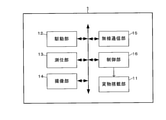
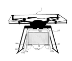
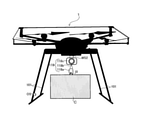
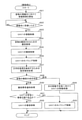
- FIG. 1 It is a figure which shows the outline structure example of the freight carrying system S. It is a figure which shows the outline structure example of UAV1. It is a figure which shows an example of the appearance of the UAV1 provided with the support part 117. It is a figure which shows an example of the appearance of the UAV1 which includes the connection part 118. It is a figure which shows the example of the functional block in the control part 16. It is a figure which shows the state that the departure control is performed with the UAV1 landing. It is a figure which shows the state that the withdrawal control is performed in the state which UAV1 is hovering. It is a flowchart which shows an example of the processing of the control unit 16 of UAV1 in Example 1.
- FIG. 1 It is a figure which shows the outline structure example of the freight carrying system S. It is a figure which shows the outline structure example of UAV1. It is a figure which shows an example of the appearance of the UAV1 provided with the support part 117. It is a figure which shows an example of the appearance of
- FIG. 1 It is a flowchart which shows an example of the processing of the control unit 16 of UAV1 in Example 2.
- FIG. It is a flowchart which shows an example of the process of the control part 16 of UAV1 in Example 3.
- FIG. It is a flowchart which shows an example of the process of the control part 16 of UAV1 in Example 4.
- FIG. 1 It is a flowchart which shows an example of the processing of the control unit 16 of UAV1 in Example 2.
- FIG. 1 is a diagram showing a schematic configuration example of the freight forwarding system S.
- the freight transport system S includes an unmanned aerial vehicle (hereinafter referred to as “UAV (Unmanned Aerial Vehicle)”) 1 flying in the atmosphere (air) and an operation management system (hereinafter referred to as “UTMS (UAV)”. Traffic Management System) ”) 2 is included.
- UAV1 and UTMS2 can communicate with each other via the communication network NW.
- the communication network NW is composed of, for example, the Internet, a mobile communication network, a radio base station thereof, and the like.
- one UAV1 is shown, but there may actually be a plurality of UAV1s.
- UAV1 can fly or autonomously fly from the ground according to remote control by the operator for the transportation of cargo (for example, delivery).
- UAV1 is also called a drone, or multicopter.
- cargo include goods, parcels, evacuation supplies, relief supplies, etc., but any cargo that can be carried by UAV1 may be used.
- UAV1 leaves (in other words, separates) the cargo at the destination of the cargo (an example of the planned movement site).
- UAV1 is managed by GCS (GroundControlStation) and can be remotely controlled by an operator from the ground.
- GCS is installed in, for example, a control terminal that can be connected to a communication network NW as an application.
- the operator is, for example, a person who operates the control terminal or a controller included in the control terminal.
- GCS may be systematized by a server or the like. In this case, the operator is, for example, a system administrator or a controller included in the server.
- UAV1 flight management includes UAV1 flight plan management, UAV1 flight status management, and UAV1 control.
- the UAV1 flight plan is a flight plan including a flight route (planned route) from the departure point (flight start point) of UAV1 to the cargo transportation destination (route point or destination point).
- the flight path is represented by, for example, the latitude and longitude on the path and may include flight altitude.
- the flight status of UAV1 is managed based on the aircraft information of UAV1.
- the aircraft information of UAV1 includes at least the position information of UAV1.
- the position information of UAV1 indicates the current position of UAV1.
- the current position of UAV1 is the flight position of UAV1 in flight.
- the aircraft information of UAV1 may include speed information of UAV1 and the like.
- the speed information indicates the flight speed of UAV1.
- FIG. 2 is a diagram showing a schematic configuration example of UAV1.
- the UAV 1 includes a cargo loading unit 11, a driving unit 12, a positioning unit 13, an imaging unit 14, a wireless communication unit 15, a control unit 16, and the like.
- the control unit 16 is an example of a control device.
- the UAV1 includes a rotor (propeller) which is a horizontal rotor, various sensors, a battery for supplying electric power to each part of the UAV1, and the like.
- Various sensors include a 3-axis accelerometer, a geomagnetic sensor and the like.
- the various sensors may include at least one of a weight sensor, a torque sensor, an optical sensor, and an ultrasonic sensor.
- the detection data detected by various sensors is output to the control unit 16.
- the UAV1 may be provided with a speaker for outputting audio.
- the cargo loading section 11 is for loading one or a plurality of cargoes, and includes at least one of a support section 117 for supporting the loaded cargo and a connecting section 118 for connecting the cargo.
- FIG. 3 is a diagram showing an example of the appearance of the UAV 1 provided with the support portion 117.
- the support portion 117 includes a storage body 117a for storing the cargo C and a drive mechanism 117b for supporting or releasing the cargo C.
- the storage body 117a may be configured to be able to store a plurality of cargo Cs.
- the drive mechanism 117b includes an actuator that converts a control signal (electrical signal) output from the control unit 16 into a mechanical operation.
- the actuator includes, for example, a motor and the like.
- the storage body 117a includes a cargo receiving 117a1 that receives the cargo C.
- the cargo receiver 117a1 is rotationally driven in the direction of the arrow by the drive mechanism 117b (that is, the cargo receiver 117a1 shifts from the closed state to the open state).
- rotational drive in other words, release operation
- the cargo C is released (in this example, dropped) from the support portion 117.
- This release operation is performed by driving the actuator in the drive mechanism 117b.
- the storage body 117a may be configured in a box shape so as to cover the side surface of the cargo C. That is, the storage body 117a may be configured as a storage box. In this case, the cargo C becomes invisible from the outside of the storage body 117a.
- the support portion 117 may include a catcher (or an arm) capable of gripping the cargo C (or a ring attached to the cargo C) instead of the cargo receiver 117a1 in order to support the cargo C. The release operation in this case is also performed by driving the actuator in the drive mechanism 117b.
- the support portion 117 may include a drive mechanism having an electromagnet capable of attracting a magnet attached to the cargo C by magnetic force instead of the drive mechanism 117b and the cargo receiver 117a1 in order to support the cargo C.
- the release operation in this case is performed by stopping the energization of the electromagnet.
- FIG. 4 is a diagram showing an example of the appearance of the UAV 1 provided with the connection portion 118.
- the connecting portion 118 sends out or winds the hook 118a for hooking the ring R attached to the cargo C, the wire 118b to which the cargo C is connected via the hook 118a, and the wire 118b.
- the reel 118c includes a motor and is driven and controlled by the control unit 16.
- the hook 118a may hook a ring R attached to a plurality of cargo Cs.
- the hook 118a may also include a drive mechanism for automatically connecting or releasing the cargo C.
- the operation of the drive mechanism (that is, the opening / closing operation of the hook 118a) is performed by driving the actuator in the drive mechanism.
- the connecting portion 118 may include a catcher (or arm) capable of gripping the cargo C itself (or a ring R attached to the cargo C) instead of the hook 118a in order to connect the cargo C. ..
- the connecting portion 118 may include, instead of the hook 118a, a drive mechanism having an electromagnet capable of attracting a magnet attached to the cargo C by magnetic force in order to connect the cargo C.
- the release operation in this case is performed by stopping the energization of the electromagnet.
- the drive unit 12 includes a motor, a rotating shaft, and the like.
- the drive unit 12 rotates a plurality of rotors by a motor driven according to a control signal output from the control unit 16, a rotating shaft, and the like.
- the positioning unit 13 includes a radio wave receiver, an altitude sensor (for example, a barometric pressure sensor, a TOF sensor), and the like.
- the positioning unit 13 receives a radio wave transmitted from a satellite of GNSS (Global Navigation Satellite System) by a radio wave receiver, and detects the current position (latitude and longitude) in the horizontal direction of UAV1 based on the radio wave.
- the current position of UAV1 is the flight position of UAV1 in flight.
- the current position in the horizontal direction of the UAV 1 may be corrected based on the image data captured by the image pickup unit 14 and the radio wave transmitted from the radio base station.
- the positioning unit 13 may detect the current position (altitude) of the UAV 1 in the vertical direction by the altitude sensor.
- the position information indicating the current position detected by the positioning unit 13 is output to the control unit 16.
- the image pickup unit 14 includes a camera (RGB camera or infrared camera).
- the image pickup unit 14 continuously images the real space within the range within the angle of view of the camera.
- the image data captured by the image pickup unit 14 is output to the control unit 16.
- the wireless communication unit 15 is responsible for controlling communication performed via the communication network NW.
- the control unit 16 includes a CPU (Central Processing Unit), a ROM (Read Only Memory), a RAM (Random Access Memory), a non-volatile memory, and the like, which are processors.
- FIG. 5 is a diagram showing an example of a functional block in the control unit 16.
- the control unit 16 functions as a departure control unit 16a, a load detection processing unit 16b, a departure success / failure determination unit 16c, an aircraft control unit 16d, and the like, as shown in FIG. 5, according to a program stored in, for example, a ROM or a non-volatile memory. do.
- the detachment control unit 16a is an example of the first control unit.
- the aircraft control unit 16d is an example of the second control unit.
- the non-volatile memory stores the machine ID that identifies the UAV1 and the address information for accessing the control server CS.
- the control unit 16 transmits the aircraft ID and aircraft information of the UAV1 to the control server CS via the wireless communication unit 15 at regular intervals or irregular intervals.
- the detachment control unit 16a is for detaching the cargo C supported by the support portion 117 or the cargo C connected by the connection portion 118 from the UAV1 while the UAV1 is flying or the UAV1 is landing. Withdrawal control is performed.
- the state in which UAV1 is flying means that UAV1 is moving in the air (that is, moving horizontally, vertically, or diagonally), or UAV1 is hovering (that is, UAV1 is hovering). It is in a state of being stationary in the air).
- the state in which UAV1 is hovering is not limited to the state in which UAV1 is completely stationary in the air, and UAV1 may move slightly (that is, if UAV1 does not land and floats in the air). good).
- the departure control unit 16a is performed by outputting a control signal to the support unit 117 or the connection unit 118.
- Such disconnection control includes, for example, control for causing the drive mechanism of the support portion 117 or the connection portion 118 to perform a release operation.
- control for causing the drive mechanism of the support portion 117 to perform the release operation is performed in a state where the UAV1 is landing, but it may be performed in a state where the UAV1 is in flight.
- FIG. 6 is a diagram showing how the departure control is performed while the UAV1 is landing. In the example of FIG.
- the cargo C is released toward the ground from the UAV1 landing at the port (takeoff and landing facility) P installed on the ground of the transportation destination.
- the cargo C may be dropped toward the ground from the UAV1 hovering over the port P installed on the ground of the transportation destination.
- the detachment control is a control for stopping the energization of the electromagnet while the UAV1 is landing (that is, the drive mechanism having the electromagnet). Control to release operation).
- FIG. 7 is a diagram showing how the withdrawal control is performed while the UAV1 is hovering.
- the cargo C is lowered toward the ground by sending out the wire 118b from the UAV1 hovering over the port P installed on the ground of the transportation destination.
- the control for causing the drive mechanism of the connection portion 118 to perform the release operation may be performed while the UAV1 is in the landing state.
- the disconnection control is a control for sending the wire 118b to the reel 118c of the connecting portion 118 (that is, lowering the cargo C).
- the above-mentioned disconnection control is, for example, a control for stopping the energization of the electromagnet while the cargo C is landing on the port P.
- the load detection processing unit 16b detects the mechanical load applied to the support unit 117 or the connection unit 118 (in other words, the mechanical load acting on the support unit 117 or the connection unit 118) after the disconnection control is performed. Load detection processing is performed. For example, the load detection processing unit 16b performs the load detection processing based on the weight data detected by the weight sensor included in the UAV1 to more easily detect the mechanical load applied to the support unit 117 or the connection unit 118. can do. In this case, the mechanical load is expressed in weight.
- the weight sensor is attached to the UAV1 at a position where the weight of the cargo C can be detected.
- the load detection process can be executed in either the state where the UAV1 is moving in the air or the state where the UAV1 is hovering, but the one performed while the UAV1 is hovering. Can detect the weight data more accurately.
- the weight sensor WS1 is attached to the upper part of the housing body 117a.
- the load detection processing unit 16b is a load for detecting the mechanical load applied to the support unit 117 based on the weight data indicating the weight of the support unit 117 (container body 117a) detected by the weight sensor WS1. Perform detection processing.
- the accuracy of detecting the mechanical load applied to the support portion 117 can be improved. For example, when the cargo C is released from the support portion 117, the weight of the housing 117a does not include the weight of the cargo C, so that the detected weight is small (that is, the mechanical load is light).
- the weight of the storage body 117a includes the weight of the cargo C, so that the detected weight becomes large.
- the case where the cargo C is not released from the support portion 117 includes, for example, the case where the cargo C is not completely released from the support portion 117 due to being caught in the storage body 117a.
- the weight sensor WS1 may be attached to the cargo receiver 117a1 so that the cargo receiver 117a1 can detect only the weight of the cargo C in the closed state.
- the cargo receiver 117a1 when the cargo receiver 117a1 is opened, the weight of the cargo C is not detected (that is, the pressure from the cargo C disappears), so it is presumed that the cargo C has been released.
- the cargo C if the cargo C is caught in the storage body 117a, the weight of the cargo C cannot be detected even though the cargo C has not been released (that is, it is erroneously assumed that the cargo C has been released). Presumed). Therefore, as shown in FIG. 3, when the weight sensor WS1 is attached to the upper part of the housing body 117a, the detection accuracy of the mechanical load applied to the entire support portion 117 can be improved.
- the weight sensor WS2 is attached to the upper part of the reel 118c.
- the load detection processing unit 16b performs load detection processing for detecting the mechanical load applied to the connection unit 118 based on the weight data indicating the weight of the connection unit 118 detected by the weight sensor WS2.
- the accuracy of detecting the mechanical load applied to the connection portion 118 can be improved. For example, when the cargo C is released from the connection portion 118, the weight of the connection portion 118 does not include the weight of the cargo C, so that the detected weight becomes smaller.
- the weight of the connection portion 118 includes the weight of the cargo C, so that the detected weight becomes large.
- the case where the cargo C is not released from the connection portion 118 includes, for example, the case where the cargo C is not completely released from the connection portion 118 due to being caught by the wire 118b or the hook 118a.
- the above mechanical load may be detected without using the weight sensor.
- the load detection processing unit 16b may detect the rotation speed of the rotor motor while the UAV1 is hovering, and perform the load detection processing based on the detected rotation speed.
- the mechanical load is expressed in revolutions per unit time. For example, when the cargo C is released from the support portion 117 or the connection portion 118, the support portion 117 or the connection portion 118 becomes lighter, so that the detected rotation speed becomes smaller. On the other hand, when the cargo C is not released from the support portion 117 or the connection portion 118, the support portion 117 or the connection portion 118 becomes heavy, so that the detected rotation speed becomes large.
- the load detection processing unit 16b determines the ascending speed of UAV1 from the flight altitude (altitude difference) and time detected by the altitude sensor in a state where the rotor motor is controlled so as to have a predetermined rotation speed. It may be calculated. Then, the load detection processing unit 16b may perform load detection processing for detecting the mechanical load applied to the support unit 117 or the connection unit 118 based on the calculated ascending speed. In this case, the mechanical load on the support 117 or the connection 118 is expressed in ascending speed. For example, when the cargo C is released from the support portion 117 or the connection portion 118, the support portion 117 or the connection portion 118 becomes lighter, so that the calculated ascending speed becomes faster. On the other hand, when the cargo C is not released from the support portion 117 or the connection portion 118, the support portion 117 or the connection portion 118 becomes heavy, so that the calculated ascending speed becomes slow.
- the load detection processing unit 16b may measure the torque of the motor of the reel 118c by a torque sensor. Then, the load detection processing unit 16b may perform load detection processing for detecting the mechanical load applied to the connection unit 118 based on the measured torque.
- the mechanical load on the connection 118 is represented by torque. For example, when the cargo C is released from the connection portion 118, the connection portion 118 becomes lighter, so that the measured torque becomes smaller. On the other hand, when the cargo C is not released from the connection portion 118, the connection portion 118 becomes heavy, so that the measured torque becomes large.
- the load detection processing unit 16b may measure the tension of the wire 118b and perform load detection processing for detecting the mechanical load applied to the connection unit 118 based on the measured tension.
- the withdrawal success / failure determination unit 16c determines the success / failure of the withdrawal of the cargo C based on the mechanical load detected by the load detection processing unit 16b.
- UAV1 can be made to take an appropriate response according to the result of the withdrawal success / failure determination of the cargo C (that is, the withdrawal success / failure status). For example, it is determined whether or not the mechanical load is larger than the threshold value in the state where the UAV1 is flying or the UAV1 is landing.
- the above threshold value is, for example, the weight (known) of the support portion 117 or the connection portion 118 when the cargo C is not mounted while the UAV1 is hovering. It is preset in the margin.
- the above threshold value is the number of revolutions of the motor when the cargo C is not mounted while the UAV1 is hovering (in other words, the cargo C is not mounted).
- the rotation speed of the motor that maintains the hovering state of UAV1) + margin is set in advance.
- the mechanical load is not larger than the threshold value (less than the threshold value), it is determined that the cargo C has been successfully removed.
- the mechanical load is larger than the threshold value, it is determined that the cargo C has failed to leave.
- the above threshold value is preset to the ascending speed (average value) when the cargo C is not loaded. In this case, if the mechanical load is not larger than the threshold value (that is, the ascending speed is slow), it is determined that the cargo C has failed to leave. On the other hand, if the mechanical load is larger than the threshold value, it is determined that the cargo C has been successfully removed.
- the success or failure of the departure of the cargo C can be determined by using the image data captured by the camera, but when the support portion 117 is provided with a storage body (storage box) in which the cargo C cannot be seen from the outside. It is difficult to determine the success or failure of the cargo C withdrawal using the image data captured by the camera. Further, when there is a blind spot where the cargo C cannot be captured depending on the mounting position of the camera, it is difficult to determine the success or failure of the cargo C withdrawal using the image data captured by the camera (this problem is particularly difficult). This is noticeable when a plurality of cargo Cs are loaded). On the other hand, by using the mechanical load detected by the load detection processing unit 16b, these problems can be solved and the success or failure of the departure of the cargo C can be accurately determined.
- the aircraft control unit 16d uses the position information acquired from the positioning unit 13, the image data acquired from the image pickup unit 14, the detection data acquired from various sensors, and the flight plan information indicating the flight plan to use the aircraft of the UAV1. Take control.
- the airframe control for example, the rotation speed of the rotor motor is controlled, and the position, attitude, and traveling direction of the UAV1 are controlled.
- the airframe control of UAV1 includes takeoff control of UAV1, movement control of UAV1, hovering control of UAV1, landing control of UAV1 and the like.
- the takeoff control of the UAV1 includes a control that does not take off the UAV1 depending on the situation.
- the flight plan information is acquired from, for example, GCS or UTMS2.
- the flight plan information includes the location information of the destination of the cargo C.
- the aircraft control unit 16d can remotely control or autonomously fly (move) the UAV1 to the destination according to the position information of the destination of the cargo C.
- the autonomous flight of the UAV1 is not limited to the autonomous flight in which the control unit 16 provided in the UAV1 controls the movement, and the autonomous flight of the UAV1 is, for example, the movement control of the cargo carrying system S as a whole. Also includes autonomous flight by performing.
- the airframe control unit 16d controls the movement of the UAV1 after the load detection processing unit 16b detects the mechanical load, depending on the mechanical load. For example, when the load detection process is performed while the UAV1 is landing, the aircraft control unit 16d either takes off the UAV1 or limits the takeoff of the UAV1 depending on the magnitude of the mechanical load. For example, the airframe control unit 16d presets a numerical range of the mechanical load. Then, the aircraft control unit 16d takes off the UAV1 when the mechanical load detected by the load detection process falls within the set numerical range (or even if the takeoff of the UAV1 is restricted in this case). good).
- the aircraft control unit 16d determines the success / failure of the movement of the UAV1 after the load detection process is performed. Different controls are performed accordingly. For example, when it is determined that the cargo C has been successfully removed, the aircraft control unit 16d controls the UAV1 to take off (the takeoff control of the UAV1). This allows UAV1 to take off safely. On the other hand, when it is determined that the cargo C has failed to leave, the aircraft control unit 16d performs control to limit the takeoff of the UAV 1 (for example, control to stop the rotor motor). As a result, the safety of UAV1 can be ensured.
- the aircraft control unit 16d moves the UAV1 to the next planned movement destination (for example, the next transportation destination, depending on the magnitude of the mechanical load). Or head to the return destination), hover UAV1 in the air, or land UAV1.
- the airframe control unit 16d presets the numerical range of the mechanical load in a plurality of stages (for example, sets the first to third numerical ranges different from each other). Then, the aircraft control unit 16d directs UAV1 to the next planned movement location when the mechanical load detected by the load detection process falls within the first numerical range, and when the mechanical load falls within the second numerical range. Hover the UAV1 in the air and land the UAV1 if it falls within the third numerical range.
- the aircraft control unit 16d determines the success / failure of the movement of the UAV1 after the load detection process is performed. Different controls are performed accordingly. For example, when it is determined that the cargo C has been successfully removed, the aircraft control unit 16d controls the UAV1 to move to the next planned movement location (movement control of the UAV1). This makes it possible to safely direct UAV1 to the next planned destination. On the other hand, when it is determined that the cargo C has failed to leave, the aircraft control unit 16d controls the UAV1 to hover in the air (UAV1 hovering control) or controls the UAV1 to land (UAV1 landing control). I do. By hovering the UAV1, the safety of the UAV1 can be ensured. Further, by landing the UAV1, it is possible to prevent the UAV1 from moving in an unstable state.
- the aircraft control unit 16d should determine whether the UAV1 can land safely. Then, when the aircraft control unit 16d determines that the UAV1 can land safely, the aircraft control unit 16d will land the UAV1. This allows the UAV1 to take off more safely. Whether or not the UAV1 can land safely may be determined based on, for example, the detection data detected by an optical sensor such as a camera. As a result, it is possible to improve the accuracy of determining whether or not the UAV1 can land safely.
- the detection data detected by the optical sensor may be image data.
- the optical sensor OS is attached to the leg 101 of the UAV1.
- the aircraft control unit 16d can determine that the cargo C does not protrude below the lower end of the leg 101 by analyzing the detection data detected by the optical sensor OS, the UAV1 can safely land. Is determined. Alternatively, whether or not UAV1 can land safely may be determined based on the winding amount of the wire 118b. As a result, it is possible to improve the accuracy of determining whether or not the UAV1 can land safely.
- the aircraft control unit 16d determines that the UAV 1 can safely land if it can be determined from the winding amount that the cargo C does not protrude below the lower end of the leg 101. On the other hand, the aircraft control unit 16d maintains the hovering of the UAV1 when it is determined that the UAV1 cannot land safely.
- FIG. 8 is a flowchart showing an example of the processing of the control unit 16 of the UAV1 in the first embodiment.
- the first embodiment is an embodiment in which the detachment control is performed in a state where the UAV1 provided with the support portion 117 is in flight.
- the control unit 16 determines whether or not the UAV1 has arrived at the destination of the cargo C (step S2). ).
- step S2 when it is determined that the cargo C has arrived at the destination of the cargo C (step S2: YES), the control unit 16 performs withdrawal control for detaching the cargo C from the UAV1 while the UAV1 is moving (step S3). ).
- the control unit 16 performs withdrawal control for detaching the cargo C from the UAV1 while the UAV1 is moving (step S3).
- the cargo C is dropped onto the port P installed at the transportation destination, for example.
- the withdrawal control may be performed while the UAV1 is hovering.
- control unit 16 controls the hovering of the UAV1 (step S4).
- the control unit 16 performs a load detection process for detecting the mechanical load applied to the support unit 117 (step S5).
- load detection processing is performed by the load detection processing unit 16b based on the weight data detected as described above, the rotation speed of the motor, or the like.
- control unit 16 determines the success or failure of the cargo C withdrawal by the withdrawal success / failure determination unit 16c based on the mechanical load detected in step S5 while the UAV1 is hovering (step S6).
- step S6 success
- step S7 the control unit 16 determines that the cargo C has been successfully removed.
- step S6 success
- step S7 the next planned movement location (for example, the next).
- the movement of the UAV1 is controlled toward the destination (transportation destination or return destination) (step S7).
- step S5 when the mechanical load detected in step S5 is larger than the threshold value (that is, when an abnormal load is applied to the support portion 117), the control unit 16 determines that the cargo C has failed to leave (step). S6: Failure), proceed to step S8.
- step S8 the control unit 16 performs withdrawal abnormality notification processing.
- a voice indicating the withdrawal abnormality is output from the speaker.
- an e-mail indicating the withdrawal abnormality may be sent to the e-mail address of the mobile terminal possessed by the staff of the port P installed at the transportation destination of the cargo C. As a result, it is possible to promptly inform the staff of the port P of the withdrawal abnormality.
- the staff notified of the withdrawal abnormality can take appropriate measures. Since the UAV1 may occupy the port P until the abnormality is recovered, in the departure abnormality notification process, a message indicating the departure abnormality may be transmitted to the control server CS together with the aircraft ID and the aircraft information of the UAV1. As a result, the control server CS can control the other UAV1 so that the port P is not used.
- control unit 16 determines whether or not the UAV1 can safely land based on the detection data detected by, for example, the optical sensor OS (step S9). For example, if it can be determined that the cargo C does not protrude below the lower end of the leg 101, it is determined that the UAV 1 can land safely. Further, if the leg portion 101 of the UAV1 is sufficiently longer than the vertical length of the cargo C, the UAV1 can safely land even if the cargo C is caught in some part of the support portion 117. Can be determined.
- step S9 determines that the UAV1 can land safely
- step S10 controls the landing of the UAV1 (step S10).
- the staff of the port P can clear the catch of the cargo C and collect the cargo C.
- control unit 16 determines that the UAV1 cannot land safely (step S9: NO)
- the control unit 16 controls to maintain hovering (step S11). After that, the control unit 16 returns the UAV 1 to the starting point or the waypoint.
- FIG. 9 is a flowchart showing an example of the processing of the control unit 16 of the UAV1 in the second embodiment.
- the second embodiment is an example in which the departure control is performed in a state where the UAV 1 provided with the support portion 117 is landing.
- the processing of steps S21 and S22 in FIG. 9 is the same as the processing of steps S1 and S2 in FIG.
- step S22 determines that the cargo C has arrived at the destination (step S22: YES)
- the control unit 16 controls the landing of the UAV1 (step S23).
- the control unit 16 performs withdrawal control for separating the cargo C from the UAV1 (step S24).
- the cargo C is released, for example, on the port P installed at the transportation destination.
- control unit 16 controls the takeoff of UAV1 (step S25).
- control unit 16 determines that the UAV1 has reached a predetermined altitude
- control unit 16 controls the hovering of the UAV1 (step S26).
- control unit 16 performs a load detection process for detecting the mechanical load applied to the support unit 117 while the UAV 1 is hovering (step S27).
- the processing of steps S28 to S33 in FIG. 9 is the same as the processing of steps S6 to S11 in FIG.
- FIG. 10 is a flowchart showing an example of processing of the control unit 16 of UAV1 in the third embodiment.
- the third embodiment is an embodiment in which the departure control is performed in a state where the UAV 1 provided with the support portion 117 is landing.
- the processing of steps S41 to S44 in FIG. 10 is the same as the processing of steps S21 to S24 in FIG.
- control unit 16 performs a load detection process for detecting the mechanical load applied to the support unit 117 while the UAV 1 is landing (step S45).
- control unit 16 determines the success or failure of the cargo C withdrawal based on the mechanical load detected in step S45 while the UAV1 is landing (step S46).
- step S45 determines that the cargo C has been successfully removed (step S46: success), and controls the takeoff of UAV1 (step S47). .. Next, the control unit 16 controls the movement of the UAV 1 toward the next planned movement destination (for example, the next transportation destination or the return destination) (step S48).
- next planned movement destination for example, the next transportation destination or the return destination
- step S45 determines that the cargo C has failed to leave (step S46: failure), and performs the withdrawal abnormality notification process as described above (step S46: failure). Step S49).
- the control unit 16 limits the takeoff of the UAV1 (step S50). As a result, the UAV1 remains landed at the port P, and the staff of the port P can clear the catch of the cargo C and collect the cargo C.
- FIG. 11 is a flowchart showing an example of the processing of the control unit 16 of the UAV1 in the fourth embodiment.
- the fourth embodiment is an embodiment in which the detachment control is performed in a state where the UAV1 provided with the connection portion 118 is in flight.
- the processing of steps S61 and S62 in FIG. 11 is the same as the processing of steps S1 and S2 in FIG.
- step S62 determines that the cargo C has arrived at the destination
- step S63 the control unit 16 controls the hovering of the UAV1 at a predetermined altitude
- step S64 the control unit 16 controls the delivery of the wire 118b (step S64).
- the cargo C connected to the wire 118b via, for example, the hook 118a is lowered.
- the control unit 16 performs withdrawal control for detaching the cargo C from the UAV1 (step S65). For example, the release operation of the drive mechanism of the hook 118a is performed. As a result, if there is no particular abnormality, the cargo C is released from, for example, the hook 118a.
- control unit 16 controls the winding of the wire 118b (step S66).
- control unit 16 performs a load detection process for detecting the mechanical load applied to the connection unit 118 while the UAV 1 is hovering (step S67).
- the control unit 16 may perform the load detection process after raising the altitude of the UAV 1 (for example, raising it by a few meters) before performing the take-up control in step S66.
- the processing of steps S68 to S70 in FIG. 11 is the same as the processing of steps S6 to S8 in FIG.
- control unit 16 determines whether or not the UAV1 can safely land based on, for example, the winding amount of the wire 118b (step S71). If it can be determined from the winding amount of the wire 118b that the cargo C does not protrude below the lower end of the leg 101, it is determined that the UAV 1 can land safely.
- step S71: YES when the control unit 16 determines that the UAV1 can land safely (step S71: YES), the control unit 16 controls the landing of the UAV1 (step S72). On the other hand, when it is determined that the UAV1 cannot land safely (step S71: NO), the control unit 16 controls to maintain hovering (step S73).
- the success or failure of the departure of the cargo C is determined based on the detected mechanical load, but the control unit 16 determines the success or failure of the departure of the cargo C.
- the UAV1 may be controlled (for example, the control shown in step S7 and subsequent steps shown in FIG. 8) according to the mechanical load.
- the detachment control for disconnecting the cargo supported by the support portion 117 of the UAV1 or connected by the connection portion 118 from the UAV1 is performed, and then the support portion 117 or the connection is performed.
- a load detection process for detecting the mechanical load applied to the unit 118 is performed, and different control is performed according to the mechanical load regarding the movement of the UAV1 after the detection of the mechanical load is performed. Since the mechanical load detected by the load detection process reflects the cargo withdrawal success / failure status, it is possible to make UAV1 take appropriate measures according to the cargo withdrawal success / failure status.
- the control unit 16 of the UAV 1 may perform a release operation detection process for detecting the release operation of the drive mechanism of the support unit 117 or the connection unit 118 before performing the load detection process. That is, the control unit 16 performs the load detection process after the release operation of the drive mechanism is detected.
- the release operation of the drive mechanism can be detected by detecting the state (rotational position, load, etc.) of the motor in the actuator.
- the drive mechanism includes an electromagnet
- the release operation of the drive mechanism is to detect whether or not the electromagnet is energized, or to detect the magnetic force generated by the electromagnet. Can be detected by.
- the release operation of the drive mechanism may be detected, for example, on condition that a control signal is output from the disconnection control unit 16a to the support unit 117 or the connection unit 118.
- a control signal is output from the disconnection control unit 16a to the support unit 117 or the connection unit 118.
- whether the drive mechanism of the support portion 117 or the connection portion 118 has an abnormality for example, there is a defect in the actuator or the electromagnet
- the drive mechanism can isolate an abnormality as to whether the cargo has not been released (for example, is caught) even though it has operated normally.
- the control unit 16 of the UAV 1 performs different control depending on the first control unit that performs detachment control, the load detection unit that performs load detection processing for detecting the mechanical load, and the mechanical load.
- the control server CS may include a first control unit, a load detection unit, a second control unit, or the like as a control device.
- the control server CS performs withdrawal control for detaching the cargo supported by the support portion 117 of the UAV1 or connected by the connection portion 118 from the UAV1 while appropriately acquiring the necessary information from the UAV1.
- a load detection process is performed to detect the mechanical load applied to the support portion 117 or the connection portion 118, and different control is performed according to the mechanical load regarding the movement of the UAV1 after the detection of the mechanical load is performed. conduct.
- the withdrawal control is performed by transmitting the withdrawal control command from the control server CS to the UAV1 (or GCS). Further, control different depending on the mechanical load is performed by transmitting a control command according to the mechanical load from the control server CS to UAV1 (or GCS).
- control server CS determines the success or failure of the cargo withdrawal based on the detected mechanical load, and responds to the result of the success / failure determination regarding the movement of the UAV1 after the load detection process is performed. You may perform different control. Further, in the above embodiment, the case where the present invention is applied to UAV1 has been described as an example, but the present invention is a manned aircraft capable of flying without the presence of a pilot in the aircraft. It is also applicable to this.
Landscapes
- Engineering & Computer Science (AREA)
- Aviation & Aerospace Engineering (AREA)
- Remote Sensing (AREA)
- Automation & Control Theory (AREA)
- Radar, Positioning & Navigation (AREA)
- Physics & Mathematics (AREA)
- General Physics & Mathematics (AREA)
- Mechanical Engineering (AREA)
- Control Of Position, Course, Altitude, Or Attitude Of Moving Bodies (AREA)
Abstract
UAV1は、支持部117により支持または接続部118により接続された貨物をUAV1から離脱させるための離脱制御を行い、その後に、支持部117または接続部118にかかる力学的負荷を検知するための負荷検知処理を行う。そして、UAV1は、当該力学的負荷の検知が行われた後におけるUAV1の移動に関して、当該力学的負荷に応じて異なる制御を行う。
Description
本発明は、航空機に搭載された貨物を航空機から離脱させるための制御を行う方法等の技術分野に関する。
従来、無人で飛行可能な航空機により貨物を運搬するため、貨物を把持する把持器や、貨物が先端に接続された支持ワイヤを備える航空機が知られている。例えば、特許文献1に開示された飛行体は、基地局からの指令に基づいて把持器が開閉駆動して、荷役を行うように構成されている。また、特許文献2に開示された無人航空機は、支持ワイヤに支持された貨物を上空から地上に向かって下降させる際に貨物の着地を検知するように構成されている。
ところで、上述したような航空機が運搬先で人手を介さず自動的に貨物を離脱させる場合(つまり、離脱制御が行われる場合)において、当該貨物が航空機のどこかの部分に引っかかるなどの理由から、当該貨物が適切に離脱しないことがある。このことは、航空機にとって望ましくない。
そこで、貨物の離脱成否状況に応じて適切な対応を図ることが可能な航空機、制御方法、及び制御装置を提供する。
上記課題を解決するために、請求項1に記載の発明は、貨物を支持するための支持部、または前記貨物を接続するための接続部を備える航空機を含むシステムにより実行される制御方法であって、前記支持部により支持または前記接続部により接続された貨物を前記航空機から離脱させるための離脱制御を行う第1制御ステップと、前記離脱制御が行われた後に、前記支持部または前記接続部にかかる力学的負荷を検知するための負荷検知処理を行う負荷検知ステップと、前記力学的負荷の検知が行われた後における前記航空機の移動に関して、当該力学的負荷に応じて異なる制御を行う第2制御ステップと、を含むことを特徴とする。かかる負荷検知処理により検知された力学的負荷には貨物の離脱成否状況が反映されるので、貨物の離脱成否状況に応じて航空機に適切な対応をとらせることができる。
請求項2に記載の発明は、請求項1に記載の制御方法において、前記制御方法は、前記力学的負荷に基づいて、前記貨物の離脱の成否判定を行う第1判定ステップを更に含み、前記第2制御ステップにおいては、前記負荷検知処理が行われた後における前記航空機の移動に関して、前記成否判定の結果に応じて異なる制御を行うことを特徴とする。これにより、貨物の離脱成否判定の結果(つまり、離脱成否状況)に応じて航空機に適切な対応をとらせることができる。
請求項3に記載の発明は、請求項2に記載の制御方法において、前記成否判定は、前記航空機が着陸している状態で行われ、前記第1判定ステップにより前記貨物の離脱が成功したと判定された場合、前記第2制御ステップにおいては、前記航空機を離陸させる制御を行うことを特徴とする。これにより、航空機を安全に離陸させることができる。
請求項4に記載の発明は、請求項2または3に記載の制御方法において、前記成否判定は、前記航空機が着陸している状態で行われ、前記第1判定ステップにより前記貨物の離脱が失敗したと判定された場合、前記第2制御ステップにおいては、前記航空機の離陸を制限する制御を行うことを特徴とする。これにより、航空機の安全を担保することができる。
請求項5に記載の発明は、請求項2に記載の制御方法において、前記成否判定は、前記航空機が飛行している状態で行われ、前記第1判定ステップにより前記貨物の離脱が成功したと判定された場合、前記第2制御ステップにおいては、前記航空機を次の移動予定地へ向かわせる制御を行うことを特徴とする。これにより、航空機を次の移動予定地へ安全に向かわせることができる。
請求項6に記載の発明は、請求項2または5に記載の制御方法において、前記成否判定は、前記航空機が飛行している状態で行われ、前記第1判定ステップにより前記貨物の離脱が失敗したと判定された場合、前記第2制御ステップにおいては、前記航空機を空中でホバリングさせる制御を行うことを特徴とする。これにより、航空機の安全を担保することができる。
請求項7に記載の発明は、請求項2に記載の制御方法において、前記成否判定は、前記航空機が飛行している状態で行われ、前記第1判定ステップにより前記貨物の離脱が失敗したと判定された場合、前記第2制御ステップにおいては、前記航空機を着陸させる制御を行うことを特徴とする。これにより、航空機が不安定の状態で移動することを防止することができる。
請求項8に記載の発明は、請求項2に記載の制御方法において、前記成否判定は、前記航空機が飛行している状態で行われ、前記制御方法は、前記第1判定ステップにより前記貨物の離脱が失敗したと判定された場合、前記航空機が安全に着陸可能であるか否かを判定する第2判定ステップを更に含み、前記第2判定ステップにより前記航空機が安全に着陸可能であると判定された場合、前記第2制御ステップにおいては、前記航空機を着陸させる制御を行うことを特徴とする。これにより、航空機をより安全に離陸させることができる。
請求項9に記載の発明は、請求項8に記載の制御方法において、前記第2判定ステップにおいては、前記航空機が備える光学センサにより検知された検知データに基づいて、前記航空機が安全に着陸可能であるか否かを判定することを特徴とする。これにより、航空機が安全に着陸可能であるか否かの判定精度を高めることができる。
請求項10に記載の発明は、請求項8に記載の制御方法において、前記接続部は、前記貨物が接続されるワイヤと、前記ワイヤの送り出しまたは巻き取りを行うリールとを含み、前記第2判定ステップにおいては、前記ワイヤの巻き取り量に基づいて、前記航空機が安全に着陸可能であるか否かを判定することを特徴とする。これにより、航空機が安全に着陸可能であるか否かの判定精度を高めることができる。
請求項11に記載の発明は、請求項1乃至10の何れか一項に記載の制御方法において、前記負荷検知ステップにおいては、前記航空機が備える重量センサにより検知された重量データに基づいて、前記負荷検知処理を行うことを特徴とする。これにより、前記支持部または前記接続部にかかる力学的負荷をより簡単に検知することができる。
請求項12に記載の発明は、請求項11に記載の制御方法において、前記負荷検知処理は、前記航空機がホバリングしている状態で行われることを特徴とする。これにより、前記支持部または前記接続部にかかる力学的負荷の検知精度を高めることができる。
請求項13に記載の発明は、請求項11または12に記載の制御方法において、前記支持部は、前記貨物を収納するための収納体を含み、前記負荷検知ステップにおいては、前記重量センサにより検知された、前記収納体の重量データに基づいて、前記負荷検知処理を行うことを特徴とする。これにより、前記支持部または前記接続部にかかる力学的負荷の検知精度を高めることができる。
請求項14に記載の発明は、請求項1乃至13の何れか一項に記載の制御方法において、前記支持部は、前記貨物を支持または解放するための機構を含み、前記制御方法は、前記機構の解放動作を検知するための解放動作検知処理を行う解放動作検知ステップを更に含み、前記負荷検知ステップにおいては、前記解放動作検知処理により前記機構の解放動作が検知された後に前記負荷検知処理を行うことを特徴とする。これにより、前記支持部の機構に異常が生じているのか、または、当該機構は正常に動作したにも関わらず貨物が解放されていないのかについて異常の切り分けを行うことができる。
請求項15に記載の発明は、請求項1乃至13の何れか一項に記載の制御方法において、前記接続部は、前記貨物を接続または解放するための機構を含み、前記制御方法は、前記機構の解放動作を検知するための解放動作検知処理を行う解放動作検知ステップを更に含み、前記負荷検知ステップにおいては、前記解放動作検知処理により前記機構の解放動作が検知された後に前記負荷検知処理を行うことを特徴とする。これにより、前記接続部の機構に異常が生じているのか、または、当該機構は正常に動作したにも関わらず貨物が解放されていないのかについて異常の切り分けを行うことができる。
請求項16に記載の発明は、請求項14または15に記載の制御方法において、前記離脱制御は、前記機構に解放動作させる制御を含むことを特徴とする。
請求項17に記載の発明は、請求項16に記載の制御方法において、前記機構は、前記アクチュエータを含み、前記解放動作は、前記アクチュエータの駆動により行われることを特徴とする。
請求項18に記載の発明は、請求項16に記載の制御方法において、前記機構は、前記電磁石を含み、前記解放動作は、前記電磁石への通電停止により行われることを特徴とする。
請求項19に記載の発明は、貨物を支持するための支持部、または前記貨物を接続するための接続部と、前記支持部により支持または前記接続部により接続された貨物を前記航空機から離脱させるための離脱制御を行う第1制御部と、前記離脱制御が行われた後に、前記支持部または前記接続部にかかる力学的負荷を検知するための負荷検知処理を行う負荷検知部と、前記力学的負荷の検知が行われた後における前記航空機の移動に関して、当該力学的負荷に応じて異なる制御を行う第2制御部と、を備えることを特徴とする。
請求項20に記載の発明は、貨物を支持するための支持部、または前記貨物を接続するための接続部を備える航空機を制御する制御装置であって、前記支持部により支持または前記接続部により接続された貨物を前記航空機から離脱させるための離脱制御を行う第1制御部と、前記離脱制御が行われた後に、前記支持部または前記接続部にかかる力学的負荷を検知するための負荷検知処理を行う負荷検知部と、前記力学的負荷の検知が行われた後における前記航空機の移動に関して、当該力学的負荷に応じて異なる制御を行う第2制御部と、を備えることを特徴とする。
本発明によれば、貨物の離脱成否状況に応じて航空機に適切な対応をとらせることができる。
以下、図面を参照して本発明の一実施形態について説明する。なお、以下の実施形態は、貨物を運搬する貨物運搬システムに対して本発明を適用した場合の実施形態である。
[1.貨物運搬システムSの構成及び動作概要]
先ず、図1を参照して、本実施形態に係る貨物運搬システムSの構成及び動作概要について説明する。図1は、貨物運搬システムSの概要構成例を示す図である。図1に示すように、貨物運搬システムSは、大気中(空中)を飛行する無人航空機(以下、「UAV(Unmanned Aerial Vehicle)」と称する)1、及び運航管理システム(以下、「UTMS(UAV Traffic Management System)」と称する)2を含んで構成される。UAV1、及びUTMS2は、通信ネットワークNWを介して互いに通信可能になっている。通信ネットワークNWは、例えば、インターネット、移動体通信ネットワーク及びその無線基地局等から構成される。なお、図1の例では、1つのUAV1を示すが実際には複数存在してよい。
先ず、図1を参照して、本実施形態に係る貨物運搬システムSの構成及び動作概要について説明する。図1は、貨物運搬システムSの概要構成例を示す図である。図1に示すように、貨物運搬システムSは、大気中(空中)を飛行する無人航空機(以下、「UAV(Unmanned Aerial Vehicle)」と称する)1、及び運航管理システム(以下、「UTMS(UAV Traffic Management System)」と称する)2を含んで構成される。UAV1、及びUTMS2は、通信ネットワークNWを介して互いに通信可能になっている。通信ネットワークNWは、例えば、インターネット、移動体通信ネットワーク及びその無線基地局等から構成される。なお、図1の例では、1つのUAV1を示すが実際には複数存在してよい。
UAV1は、貨物の運搬(例えば、配送)のために、地上からオペレータによる遠隔操縦に従って飛行、または自律的に飛行することが可能になっている。UAV1は、ドローン、またはマルチコプタとも呼ばれる。貨物の例として、商品、宅配物、避難物資、救援物資等が挙げられるが、UAV1が運搬できる貨物であればどのような物品であってもよい。UAV1は、貨物の運搬先(移動予定地の一例)において貨物を離脱(換言すると、切り離し)する。なお、UAV1は、GCS(Ground Control Station)により管理され、地上からオペレータにより遠隔操作可能になっている。GCSは、例えば、アプリケーションとして通信ネットワークNWに接続可能な操縦端末に搭載される。この場合、オペレータは、例えば、操縦端末を操作する人、または操縦端末が備えるコントローラである。或いは、GCSは、サーバ等によりシステム化されてもよい。この場合、オペレータは、例えば、システム管理者、またはサーバが備えるコントローラである。
UTMS2は、制御サーバCSを含む1以上のサーバ等を備えて構成される。UTMS2は、UAV1の運航を管理する。UAV1の運航管理には、UAV1の運航計画の管理、UAV1の飛行状況の管理、及びUAV1の制御が含まれる。UAV1の運航計画とは、UAV1の出発地点(飛行開始地点)から貨物の運搬先(経由地点、または目的地点)までの飛行経路(予定経路)等を含む飛行計画である。飛行経路は、例えば、その経路上の緯度及び経度で表され、飛行高度を含んでもよい。UAV1の飛行状況の管理は、UAV1の航空機情報に基づいて行われる。UAV1の航空機情報には、少なくともUAV1の位置情報が含まれる。UAV1の位置情報は、UAV1の現在位置を示す。UAV1の現在位置とは、飛行中のUAV1の飛行位置である。UAV1の航空機情報には、UAV1の速度情報等が含まれてもよい。速度情報は、UAV1の飛行速度を示す。
[2.UAV1の構成及び機能概要]
次に、図2等を参照してUAV1の構成及び機能概要について説明する。図2は、UAV1の概要構成例を示す図である。図2に示すように、UAV1は、貨物搭載部11、駆動部12、測位部13、撮像部14、無線通信部15、及び制御部16等を備える。制御部16は、制御装置の一例である。図示しないが、UAV1は、水平回転翼であるロータ(プロペラ)、各種センサ、及びUAV1の各部へ電力を供給するバッテリ等を備える。各種センサには、3軸加速度センサ、及び地磁気センサ等が含まれる。また、各種センサには、重量センサ、トルクセンサ、光学センサ、及び超音波センサのうち少なくとも何れかのセンサが含まれてもよい。各種センサにより検知された検知データは、制御部16へ出力される。なお、UAV1は、音声を出力するためのスピーカを備えてもよい。
次に、図2等を参照してUAV1の構成及び機能概要について説明する。図2は、UAV1の概要構成例を示す図である。図2に示すように、UAV1は、貨物搭載部11、駆動部12、測位部13、撮像部14、無線通信部15、及び制御部16等を備える。制御部16は、制御装置の一例である。図示しないが、UAV1は、水平回転翼であるロータ(プロペラ)、各種センサ、及びUAV1の各部へ電力を供給するバッテリ等を備える。各種センサには、3軸加速度センサ、及び地磁気センサ等が含まれる。また、各種センサには、重量センサ、トルクセンサ、光学センサ、及び超音波センサのうち少なくとも何れかのセンサが含まれてもよい。各種センサにより検知された検知データは、制御部16へ出力される。なお、UAV1は、音声を出力するためのスピーカを備えてもよい。
貨物搭載部11は、1または複数の貨物を搭載するものであり、搭載された貨物を支持するための支持部117と該貨物を接続するための接続部118との少なくとも何れか一方を含む。図3は、支持部117を備えるUAV1の外観の一例を示す図である。支持部117は、図3に示すように、貨物Cを収納するための収納体117aと、貨物Cを支持または解放するための駆動機構117bとを含む。収納体117aは、複数の貨物Cを収納可能に構成されてもよい。駆動機構117bは、制御部16から出力される制御信号(電気信号)を機械的動作に変換するアクチュエータを含む。アクチュエータは、例えばモータ等を含んで構成される。また、収納体117aは、貨物Cを受ける貨物受け117a1を含む。貨物受け117a1は、駆動機構117bにより矢印方向に回転駆動する(つまり、貨物受け117a1が閉状態から開状態に移行する)。このような回転駆動(換言すると、解放動作)により、支持部117から貨物Cが解放(この例では、落下)される。かかる解放動作は、駆動機構117bにおけるアクチュエータの駆動により行われる。
なお、図3の例では、収納体117aにより貨物Cの側面が覆われていないため、収納体117aの外側から貨物Cが視認可能になっている。しかし、収納体117aは、貨物Cの側面を覆うように箱状に構成されてもよい。つまり、収納体117aは、収納箱として構成されてもよい。この場合、収納体117aの外側から貨物Cが視認不能となる。また、支持部117は、貨物Cを支持するために、貨物受け117a1に代えて、貨物C(または、貨物Cに取り付けられたリング)を把持可能なキャッチャー(または、アーム)を含んでもよい。この場合の解放動作も、駆動機構117bにおけるアクチュエータの駆動により行われる。或いは、支持部117は、貨物Cを支持するために、駆動機構117b及び貨物受け117a1に代えて、貨物Cに取り付けられた磁石を磁力により引き寄せ可能な電磁石を有する駆動機構を含んでもよい。この場合の解放動作は、当該電磁石への通電停止により行われる。
図4は、接続部118を備えるUAV1の外観の一例を示す図である。接続部118は、図4に示すように、貨物Cに取り付けられたリングRを引っ掛けるフック118aと、フック118aを介して貨物Cが接続されるワイヤ118bと、ワイヤ118bの送り出しまたは巻き取りを行うリール(ウインチ)118cとを含む。リール118cは、モータを含み、制御部16により駆動制御される。フック118aは、複数の貨物Cに取り付けられたリングRを引っ掛けるものであってもよい。また、フック118aは、貨物Cを自動的に接続または解放するための駆動機構を含んでもよい。当該駆動機構の動作(つまり、フック118aの開閉動作)は、当該駆動機構におけるアクチュエータの駆動により行われる。なお、接続部118は、貨物Cを接続するために、フック118aに代えて、貨物C自体(または、貨物Cに取り付けられたリングR)を把持可能なキャッチャー(または、アーム)を含んでもよい。或いは、接続部118は、貨物Cを接続するために、フック118aに代えて、貨物Cに取り付けられた磁石を磁力により引き寄せ可能な電磁石を有する駆動機構を含んでもよい。この場合の解放動作は、当該電磁石への通電停止により行われる。
駆動部12は、モータ及び回転軸等を備える。駆動部12は、制御部16から出力された制御信号に従って駆動するモータ及び回転軸等により複数のロータを回転させる。測位部13は、電波受信機、及び高度センサ(例えば、気圧センサやTOFセンサ)等を備える。測位部13は、例えば、GNSS(Global Navigation Satellite System)の衛星から発信された電波を電波受信機により受信し、当該電波に基づいてUAV1の水平方向の現在位置(緯度及び経度)を検出する。UAV1の現在位置は、飛行中のUAV1の飛行位置である。なお、UAV1の水平方向の現在位置は、撮像部14により撮像された画像データや上記無線基地局から発信された電波に基づいて補正されてもよい。
さらに、測位部13は、高度センサによりUAV1の垂直方向の現在位置(高度)を検出してもよい。測位部13により検出された現在位置を示す位置情報は、制御部16へ出力される。撮像部14は、カメラ(RGBカメラまたは赤外線カメラ)を備える。撮像部14は、カメラの画角に収まる範囲内の実空間を連続的に撮像する。撮像部14により撮像された画像データは、制御部16へ出力される。無線通信部15は、通信ネットワークNWを介して行われる通信の制御を担う。
制御部16は、プロセッサであるCPU(Central Processing Unit)、ROM(Read Only Memory)、RAM(Random Access Memory)、及び不揮発性メモリ等を備える。図5は、制御部16における機能ブロック例を示す図である。制御部16は、例えばROMまたは不揮発性メモリに記憶されたプログラムに従って、図5に示すように、離脱制御部16a、負荷検知処理部16b、離脱成否判定部16c、及び機体制御部16d等として機能する。ここで、離脱制御部16aは、第1制御部の一例である。機体制御部16dは、第2制御部の一例である。なお、不揮発性メモリには、UAV1を識別する機体ID、及び制御サーバCSへアクセスするためのアドレス情報が記憶されている。制御部16は、UAV1の機体ID及び航空機情報を、一定間隔または不定間隔で無線通信部15を介して制御サーバCSへ送信する。
離脱制御部16aは、UAV1が飛行している状態、またはUAV1が着陸している状態において、支持部117により支持された貨物C、または接続部118により接続された貨物CをUAV1から離脱させるための離脱制御を行う。ここで、UAV1が飛行している状態とは、UAV1が空中を移動(つまり、水平方向、垂直方向、または斜め方向に移動)している状態、またはUAV1がホバリングしている(つまり、UAV1が空中で静止している)状態である。ただし、UAV1がホバリングしている状態は、UAV1が空中で完全に静止した状態に限定されず、UAV1が多少の移動が発生してもよい(つまり、UAV1が着陸せず空中に浮いていればよい)。
UAV1から貨物Cを離脱させるため離脱制御は、離脱制御部16aが支持部117または接続部118へ制御信号を出力することにより行われる。かかる離脱制御には、例えば、支持部117または接続部118の駆動機構に解放動作させる制御が含まれる。ここで、支持部117の駆動機構に解放動作させる制御は、UAV1が着陸している状態で行われることが望ましいが、UAV1が飛行している状態で行われてもよい。図6は、UAV1が着陸している状態で離脱制御が行われる様子を示す図である。図6の例では、運搬先の地面に設置されたポート(離着陸施設)Pに着陸しているUAV1から貨物Cが地面方向に解放される。ただし、貨物の種類(例えば、落下させても壊れない物)によっては、運搬先の地面に設置されたポートPの上空にホバリングしているUAV1から貨物Cが地面方向に投下されてもよい。なお、上述した電磁石を有する駆動機構が支持部117に含まれる場合、上記離脱制御は、UAV1が着陸している状態で当該電磁石への通電を停止させる制御(つまり、当該電磁石を有する駆動機構に解放動作させる制御)である。
一方、接続部118の駆動機構に解放動作させる制御は、UAV1がホバリングしている状態で行われる。図7は、UAV1がホバリングしている状態で離脱制御が行われる様子を示す図である。図7の例では、運搬先の地面に設置されたポートPの上空にホバリングしているUAV1からワイヤ118bの送り出しが行われることによって貨物Cが地面方向に降下されている。なお、接続部118の駆動機構に解放動作させる制御は、UAV1が着陸状態で行われてもよい。また、図7の例において、貨物Cがフック118aから手動で外される場合、上記離脱制御は、接続部118のリール118cにワイヤ118bを送り出させる(つまり、貨物Cを降下させる)制御ということもできる。また、上述した電磁石を有する駆動機構が接続部118に含まれる場合、上記離脱制御は、例えば貨物CがポートPに着地している状態で当該電磁石への通電を停止させる制御である。
負荷検知処理部16bは、上記離脱制御が行われた後に、支持部117または接続部118にかかる力学的負荷(換言すると、支持部117または接続部118に作用する力学的負荷)を検知するための負荷検知処理を行う。例えば、負荷検知処理部16bは、UAV1が備える重量センサにより検知された重量データに基づいて、上記負荷検知処理を行うことにより、支持部117または接続部118にかかる力学的負荷をより簡単に検知することができる。この場合、力学的負荷は、重量で表される。重量センサは、UAV1において貨物Cの重量を検知可能な位置に取り付けられる。なお、上記負荷検知処理は、UAV1が空中を移動している状態と、UAV1がホバリングしている状態との何れの状態でも実行可能であるが、UAV1がホバリングしている状態で行われた方が上記重量データをより正確に検知することができる。
図3の例では、重量センサWS1が収納体117aの上部に取り付けられている。この場合、負荷検知処理部16bは、重量センサWS1により検知された、支持部117(収納体117a)の重量を示す重量データに基づいて、支持部117にかかる力学的負荷を検知するための負荷検知処理を行う。これにより、支持部117にかかる力学的負荷の検知精度を高めることができる。例えば、貨物Cが支持部117から解放されている場合、収納体117aの重量には貨物Cの重量は含まれていないので、検知された重量は小さくなる(つまり、力学的負荷が軽い)。一方、貨物Cが支持部117から解放されていない場合、収納体117aの重量には貨物Cの重量が含まれているので、検知された重量は大きくなる。貨物Cが支持部117から解放されていない場合には、例えば、貨物Cが収納体117a内に引っかかっていることで支持部117から完全に解放されていない場合も含まれる。
なお、重量センサWS1は、貨物受け117a1が閉状態で貨物Cの重量だけを検知できるように貨物受け117a1に取り付けられてもよい。この場合、貨物受け117a1が開状態になると、貨物Cの重量が検知されなくなる(つまり、貨物Cからの圧力がなくなる)ので、貨物Cが解放されたものと推定される。ただし、この場合、貨物Cが収納体117a内に引っかかっていると、貨物Cが解放されていないにも関わらず、貨物Cの重量が検知されなくなる(つまり、貨物Cが解放されたものと誤推定される)。そのため、図3に示すように、重量センサWS1が収納体117aの上部に取り付けられている方が、支持部117の全体にかかる力学的負荷の検知精度を高めることができる。
一方、図4の例では、重量センサWS2がリール118cの上部に取り付けられている。この場合、負荷検知処理部16bは、重量センサWS2により検知された、接続部118の重量を示す重量データに基づいて、接続部118にかかる力学的負荷を検知するための負荷検知処理を行う。これにより、接続部118にかかる力学的負荷の検知精度を高めることができる。例えば、貨物Cが接続部118から解放されている場合、接続部118の重量には貨物Cの重量は含まれていないので、検知された重量は小さくなる。一方、貨物Cが接続部118から解放されていない場合、接続部118の重量には貨物Cの重量が含まれているので、検知された重量は大きくなる。貨物Cが接続部118から解放されていない場合には、例えば、貨物Cがワイヤ118bやフック118aに引っかかっていることで接続部118から完全に解放されていない場合も含まれる。
また、重量センサが用いられることなく、上記力学的負荷が検知されてもよい。例えば、負荷検知処理部16bは、UAV1がホバリングしている状態で、ロータのモータの回転数を検知し、検知された回転数に基づいて、上記負荷検知処理を行ってもよい。この場合、力学的負荷は、単位時間あたりの回転数で表される。例えば、貨物Cが支持部117または接続部118から解放されている場合、支持部117または接続部118は軽くなるので、検知された回転数は小さくなる。一方、貨物Cが支持部117または接続部118から解放されていない場合、支持部117または接続部118は重くなるので、検知された回転数は大きくなる。
別の例として、負荷検知処理部16bは、所定の回転数となるようにロータのモータを制御した状態で、高度センサにより検知された飛行高度(高度差)と時間とからUAV1の上昇速度を算出してもよい。そして、負荷検知処理部16bは、当該算出された上昇速度に基づいて、支持部117または接続部118にかかる力学的負荷を検知するための負荷検知処理を行ってもよい。この場合、支持部117または接続部118にかかる力学的負荷は、上昇速度で表される。例えば、貨物Cが支持部117または接続部118から解放されている場合、支持部117または接続部118は軽くなるので、算出された上昇速度は速くなる。一方、貨物Cが支持部117または接続部118から解放されていない場合、支持部117または接続部118は重くなるので、算出された上昇速度は遅くなる。
或いは、UAV1が接続部118を備える場合、負荷検知処理部16bは、トルクセンサによりリール118cのモータのトルクを計測してもよい。そして、負荷検知処理部16bは、当該計測されたトルクに基づいて、接続部118にかかる力学的負荷を検知するための負荷検知処理を行ってもよい。この場合、接続部118にかかる力学的負荷は、トルクで表される。例えば、貨物Cが接続部118から解放されている場合、接続部118は軽くなるので、測定されたトルクは小さくなる。一方、貨物Cが接続部118から解放されていない場合、接続部118は重くなるので、測定されたトルクは大きくなる。或いは、負荷検知処理部16bは、ワイヤ118bの張力を計測し、当該計測された張力に基づいて、接続部118にかかる力学的負荷を検知するための負荷検知処理を行ってもよい。
離脱成否判定部16cは、負荷検知処理部16bにより検知された力学的負荷に基づいて、貨物Cの離脱の成否判定を行う。これにより、貨物Cの離脱成否判定の結果(つまり、離脱成否状況)に応じてUAV1に適切な対応をとらせることができる。例えば、UAV1が飛行している状態、またはUAV1が着陸している状態で、力学的負荷が閾値より大きいか否かが判定される。ここで、力学的負荷が重量で表される場合、上記閾値は、例えば、UAV1がホバリングしている状態で貨物Cが搭載されていない場合の支持部117または接続部118の重量(既知)+マージンに予め設定される。或いは、力学的負荷が回転数で表される場合、上記閾値は、UAV1がホバリングしている状態で貨物Cが搭載されていない場合のモータの回転数(換言すると、貨物Cが搭載されていない場合にUAV1のホバリング状態が維持されるモータの回転数)+マージンに予め設定される。
そして、当該力学的負荷が閾値より大きくない(閾値未満の)場合、貨物Cの離脱が成功したと判定される。一方、当該力学的負荷が閾値より大きい場合、貨物Cの離脱が失敗したと判定される。或いは、力学的負荷が上昇速度で表される場合、上記閾値は、貨物Cが搭載されていない場合の上昇速度(平均値)に予め設定される。この場合、当該力学的負荷が閾値より大きくない場合(つまり、上昇速度が遅い)、貨物Cの離脱が失敗したと判定される。一方、当該力学的負荷が閾値より大きい場合、貨物Cの離脱が成功したと判定される。
ところで、貨物Cの離脱の成否は、カメラにより撮像された画像データを用いても判定可能であるが、外側から貨物Cが視認不能な収納体(収納箱)が支持部117に備えられる場合、カメラにより撮像された画像データを用いて、貨物Cの離脱の成否を判定することは困難である。また、カメラの取り付け位置によって貨物Cを捉えられない死角がある場合、カメラにより撮像された画像データを用いて、貨物Cの離脱の成否を判定することは困難である(この課題は、特に、貨物Cが複数積載される場合に顕著となる)。これに対し、負荷検知処理部16bにより検知された力学的負荷を用いることで、これらの課題を解決し、貨物Cの離脱の成否判定を正確に行うことができる。
機体制御部16dは、測位部13から取得された位置情報、撮像部14から取得された画像データ、各種センサから取得された検出データ、及び飛行計画を示す飛行計画情報を用いて、UAV1の機体制御を行う。当該機体制御では、例えば、ロータのモータの回転数の制御、UAV1の位置、姿勢及び進行方向の制御が行われる。また、UAV1の機体制御には、UAV1の離陸制御、UAV1の移動制御、UAV1のホバリング制御、及びUAV1の着陸制御等が含まれる。ここで、UAV1の離陸制御には、状況によってはUAV1を離陸させない制御も含まれる。なお、飛行計画情報は、例えばGCSまたはUTMS2から取得される。飛行計画情報には、貨物Cの運搬先の位置情報が含まれる。機体制御部16dは、貨物Cの運搬先の位置情報に従ってUAV1を当該運搬先へ遠隔操縦または自律的に飛行(移動)させることができる。UAV1の自律的な飛行は、UAV1に備えられる制御部16が移動制御を行うことによる自律飛行に限定されるものではなく、UAV1の自律的な飛行には、例えば貨物運搬システムS全体として移動制御を行うことによる自律飛行も含まれる。
さらに、機体制御部16dは、負荷検知処理部16bによる力学的負荷の検知が行われた後におけるUAV1の移動に関して、当該力学的負荷に応じて異なる制御を行う。例えば、UAV1が着陸している状態で上記負荷検知処理が行われた場合、機体制御部16dは、当該力学的負荷の大きさによって、UAV1を離陸させるか、またはUAV1の離陸を制限する。例えば、機体制御部16dは、力学的負荷の数値範囲を予め設定する。そして、機体制御部16dは、上記負荷検知処理により検知された力学的負荷が、設定された数値範囲内に入る場合に、UAV1を離陸させる(或いは、この場合、UAV1の離陸を制限してもよい)。
また、UAV1が着陸している状態で貨物Cの離脱の成否判定が行われた場合、機体制御部16dは、上記負荷検知処理が行われた後におけるUAV1の移動に関して、上記成否判定の結果に応じて異なる制御を行う。例えば、貨物Cの離脱が成功したと判定された場合、機体制御部16dは、UAV1を離陸させる制御(UAV1の離陸制御)を行う。これにより、UAV1を安全に離陸させることができる。一方、貨物Cの離脱が失敗したと判定された場合、機体制御部16dは、UAV1の離陸を制限する制御(例えば、ロータのモータを停止する制御)を行う。これにより、UAV1の安全を担保することができる。
また、UAV1が飛行している状態で上記負荷検知処理が行われた場合、機体制御部16dは、当該力学的負荷の大きさによって、UAV1を次の移動予定地(例えば、次の運搬先、または帰還先)へ向かわせるか、UAV1を空中でホバリングさせるか、または、UAV1を着陸させる。例えば、機体制御部16dは、力学的負荷の数値範囲を複数段階で予め設定(例えば、互いに異なる第1~第3数値範囲を設定)する。そして、機体制御部16dは、上記負荷検知処理により検知された力学的負荷が、第1数値範囲内に入る場合にUAV1を次の移動予定地へ向かわせ、第2数値範囲内に入る場合にUAV1を空中でホバリングさせ、第3数値範囲内に入る場合にUAV1を着陸させる。
また、UAV1が飛行している状態で貨物Cの離脱の成否判定が行われた場合、機体制御部16dは、上記負荷検知処理が行われた後におけるUAV1の移動に関して、上記成否判定の結果に応じて異なる制御を行う。例えば、貨物Cの離脱が成功したと判定された場合、機体制御部16dは、UAV1を次の移動予定地へ向かわせる制御(UAV1の移動制御)を行う。これにより、UAV1を次の移動予定地へ安全に向かわせることができる。一方、貨物Cの離脱が失敗したと判定された場合、機体制御部16dは、UAV1を空中でホバリングさせる制御(UAV1のホバリング制御)を行うか、またはUAV1を着陸させる制御(UAV1の着陸制御)を行う。UAV1をホバリングさせることにより、UAV1の安全を担保することができる。また、UAV1を着陸させることにより、UAV1が不安定の状態で移動することを防止することができる。
なお、貨物Cの離脱が失敗したと判定された場合、機体制御部16dは、UAV1が安全に着陸可能であるか否かを判定するとよい。そして、機体制御部16dは、UAV1が安全に着陸可能であると判定した場合に、UAV1を着陸させる。これにより、UAV1をより安全に離陸させることができる。UAV1が安全に着陸可能であるか否かは、例えば、カメラ等の光学センサにより検知された検知データに基づいて行われるとよい。これにより、UAV1が安全に着陸可能であるか否かの判定精度を高めることができる。なお、光学センサにより検知された検知データは、画像データであってもよい。
図3及び図4の例では、光センサOSがUAV1の脚部101に取り付けられている。この場合、機体制御部16dは、光センサOSにより検知された検知データを解析することで貨物Cが脚部101の下端より下に突出していないと判断できる場合、UAV1が安全に着陸可能であると判定する。或いは、UAV1が安全に着陸可能であるか否かは、ワイヤ118bの巻き取り量に基づいて行われてもよい。これにより、UAV1が安全に着陸可能であるか否かの判定精度を高めることができる。この場合、機体制御部16dは、巻き取り量から貨物Cが脚部101の下端より下に突出していないと判断できる場合、UAV1が安全に着陸可能であると判定する。一方、機体制御部16dは、UAV1が安全に着陸可能でないと判定した場合に、UAV1のホバリングを維持させる。
[3.UAV1の動作]
次に、UAV1の動作について、実施例1~実施例4に分けて説明する。なお、以下に説明する動作は、出発地点または経由地点においてUAV1に貨物Cが搭載され、当該UAV1が離陸した後の動作である。
次に、UAV1の動作について、実施例1~実施例4に分けて説明する。なお、以下に説明する動作は、出発地点または経由地点においてUAV1に貨物Cが搭載され、当該UAV1が離陸した後の動作である。
(実施例1)
先ず、図8を参照して、UAV1の動作の実施例1について説明する。図8は、実施例1におけるUAV1の制御部16の処理の一例を示すフローチャートである。実施例1は、支持部117を備えるUAV1が飛行している状態で離脱制御が行われる場合の実施例である。図8において、貨物Cの運搬先に向けてUAV1の移動制御が開始(ステップS1)された後、制御部16は、UAV1が貨物Cの運搬先に到着したか否かを判定する(ステップS2)。
先ず、図8を参照して、UAV1の動作の実施例1について説明する。図8は、実施例1におけるUAV1の制御部16の処理の一例を示すフローチャートである。実施例1は、支持部117を備えるUAV1が飛行している状態で離脱制御が行われる場合の実施例である。図8において、貨物Cの運搬先に向けてUAV1の移動制御が開始(ステップS1)された後、制御部16は、UAV1が貨物Cの運搬先に到着したか否かを判定する(ステップS2)。
そして、制御部16は、貨物Cの運搬先に到着したと判定した場合(ステップS2:YES)、UAV1が移動している状態で貨物CをUAV1から離脱させるための離脱制御を行う(ステップS3)。これにより、特に異常がなければ、例えば運搬先に設置されたポートP上に貨物Cが投下される。なお、上記離脱制御は、UAV1がホバリングしている状態で行われてもよい。
次いで、制御部16は、UAV1のホバリング制御を行う(ステップS4)。これによりUAV1がホバリングしている状態において、制御部16は、支持部117にかかる力学的負荷を検知するための負荷検知処理を行う(ステップS5)。例えば、上述したように検知された重量データまたはモータの回転数等に基づいて負荷検知処理部16bにより負荷検知処理が行われる。
次いで、制御部16は、UAV1がホバリングしている状態で、ステップS5で検知された力学的負荷に基づいて、離脱成否判定部16cにより、貨物Cの離脱の成否判定を行う(ステップS6)。
そして、制御部16は、ステップS5で検知された力学的負荷が閾値以下である場合、貨物Cの離脱が成功したと判定し(ステップS6:成功)、次の移動予定地(例えば、次の運搬先、または帰還先)へ向けてUAV1の移動制御を行う(ステップS7)。
一方、制御部16は、ステップS5で検知された力学的負荷が閾値より大きい場合(つまり、異常な負荷が支持部117にかかっている場合)、貨物Cの離脱が失敗したと判定し(ステップS6:失敗)、ステップS8へ進む。
ステップS8では、制御部16は、離脱異常通知処理を行う。かかる離脱異常通知処理では、離脱異常を示す音声がスピーカから出力される。また、離脱異常通知処理では、貨物Cの運搬先に設置されたポートPのスタッフが所持する携帯端末のメールアドレス宛に離脱異常を示すメールが送信されてもよい。これにより、ポートPのスタッフに離脱異常を迅速に伝えることができる。
例えば、貨物Cが支持部117のどこかの部分に引っかかっている場合、離脱異常が通知されたスタッフが適切に対応することができる。なお、UAV1が異常復旧までポートPを占有する可能性があるため、離脱異常通知処理では、UAV1の機体ID及び航空機情報と共に、離脱異常を示すメッセージが制御サーバCSへ送信されてもよい。これにより、制御サーバCSは、他のUAV1が当該ポートPを利用しないように制御することができる。
次いで、制御部16は、例えば光学センサOSにより検知された検知データに基づいて、UAV1が安全に着陸可能であるか否かを判定する(ステップS9)。例えば、貨物Cが脚部101の下端より下に突出していないと判断できる場合、UAV1が安全に着陸可能であると判定される。また、UAV1の脚部101が貨物Cの垂直方向の長さに比べて十分に長い場合、貨物Cが支持部117のどこかの部分に引っかかっていたとしても、UAV1が安全に着陸可能であると判定することができる。
そして、制御部16は、UAV1が安全に着陸可能であると判定した場合(ステップS9:YES)、UAV1の着陸制御を行う(ステップS10)。これにより、UAV1がポートPに着陸することで、ポートPのスタッフが貨物Cの引っかかりを解消して当該貨物Cを回収することができる。
一方、制御部16は、UAV1が安全に着陸可能でないと判定した場合(ステップS9:NO)、ホバリングを維持させる制御を行う(ステップS11)。その後、制御部16は、UAV1を出発地点または経由地点に帰還させる。
(実施例2)
次に、図9を参照して、UAV1の動作の実施例2について説明する。図9は、実施例2におけるUAV1の制御部16の処理の一例を示すフローチャートである。実施例2は、支持部117を備えるUAV1が着陸している状態で離脱制御が行われる場合の実施例である。なお、図9におけるステップS21及びS22の処理は、図8におけるステップS1及びS2の処理と同様である。
次に、図9を参照して、UAV1の動作の実施例2について説明する。図9は、実施例2におけるUAV1の制御部16の処理の一例を示すフローチャートである。実施例2は、支持部117を備えるUAV1が着陸している状態で離脱制御が行われる場合の実施例である。なお、図9におけるステップS21及びS22の処理は、図8におけるステップS1及びS2の処理と同様である。
制御部16は、貨物Cの運搬先に到着したと判定した場合(ステップS22:YES)、UAV1の着陸制御を行う(ステップS23)。これにより、UAV1がポートPに着陸した後、制御部16は、貨物CをUAV1から離脱させるための離脱制御を行う(ステップS24)。これにより、特に異常がなければ、例えば運搬先に設置されたポートP上に貨物Cが解放される。
次いで、制御部16は、UAV1の離陸制御を行う(ステップS25)。次いで、制御部16は、UAV1が所定高度に達したと判断した場合、UAV1のホバリング制御を行う(ステップS26)。次いで、制御部16は、UAV1がホバリングしている状態において、支持部117にかかる力学的負荷を検知するための負荷検知処理を行う(ステップS27)。なお、図9におけるステップS28~S33の処理は、図8におけるステップS6~S11の処理と同様である。
(実施例3)
次に、図10を参照して、UAV1の動作の実施例3について説明する。図10は、実施例3におけるUAV1の制御部16の処理の一例を示すフローチャートである。実施例3は、支持部117を備えるUAV1が着陸している状態で離脱制御が行われる場合の実施例である。なお、図10におけるステップS41~S44の処理は、図9におけるステップS21~S24の処理と同様である。
次に、図10を参照して、UAV1の動作の実施例3について説明する。図10は、実施例3におけるUAV1の制御部16の処理の一例を示すフローチャートである。実施例3は、支持部117を備えるUAV1が着陸している状態で離脱制御が行われる場合の実施例である。なお、図10におけるステップS41~S44の処理は、図9におけるステップS21~S24の処理と同様である。
次いで、制御部16は、UAV1が着陸している状態において、支持部117にかかる力学的負荷を検知するための負荷検知処理を行う(ステップS45)。次いで、制御部16は、UAV1が着陸している状態で、ステップS45で検知された力学的負荷に基づいて、貨物Cの離脱の成否判定を行う(ステップS46)。
そして、制御部16は、ステップS45で検知された力学的負荷が閾値以下である場合、貨物Cの離脱が成功したと判定し(ステップS46:成功)、UAV1の離陸制御を行う(ステップS47)。次いで、制御部16は、次の移動予定地(例えば、次の運搬先、または帰還先)へ向けてUAV1の移動制御を行う(ステップS48)。
一方、制御部16は、ステップS45で検知された力学的負荷が閾値より大きい場合、貨物Cの離脱が失敗したと判定し(ステップS46:失敗)、上述したように離脱異常通知処理を行う(ステップS49)。次いで、制御部16は、UAV1の離陸を制限する(ステップS50)。これにより、UAV1はポートPに着陸したままとなり、当該ポートPのスタッフが貨物Cの引っかかりを解消して当該貨物Cを回収することができる。
(実施例4)
次に、図11を参照して、UAV1の動作の実施例4について説明する。図11は、実施例4におけるUAV1の制御部16の処理の一例を示すフローチャートである。実施例4は、接続部118を備えるUAV1が飛行している状態で離脱制御が行われる場合の実施例である。なお、図11におけるステップS61及びS62の処理は、図8におけるステップS1及びS2の処理と同様である。
次に、図11を参照して、UAV1の動作の実施例4について説明する。図11は、実施例4におけるUAV1の制御部16の処理の一例を示すフローチャートである。実施例4は、接続部118を備えるUAV1が飛行している状態で離脱制御が行われる場合の実施例である。なお、図11におけるステップS61及びS62の処理は、図8におけるステップS1及びS2の処理と同様である。
そして、制御部16は、貨物Cの運搬先に到着したと判定した場合(ステップS62:YES)、所定高度においてUAV1のホバリング制御を行う(ステップS63)。これによりUAV1がホバリングしている状態において、制御部16は、ワイヤ118bの送り出し制御を行う(ステップS64)。これにより、例えばフック118aを介してワイヤ118bに接続された貨物Cが降下される。
次いで、制御部16は、例えば貨物CがポートPに到達した場合(例えばワイヤ118bの送り出し量に基づいて判断)に、当該貨物CをUAV1から離脱させるための離脱制御を行う(ステップS65)。例えば、フック118aの駆動機構の解放動作が行われる。これにより、特に異常がなければ、例えばフック118aから貨物Cが解放される。
次いで、制御部16は、ワイヤ118bの巻き取り制御を行う(ステップS66)。次いで、制御部16は、UAV1がホバリングしている状態で、接続部118にかかる力学的負荷を検知するための負荷検知処理を行う(ステップS67)。ここで、制御部16は、ステップS66で巻き取り制御を行う前に、UAV1の高度を上昇(例えば、数mだけ上昇)させた上で負荷検知処理を行ってもよい。なお、図11におけるステップS68~S70の処理は、図8におけるステップS6~S8の処理と同様である。
次いで、制御部16は、例えばワイヤ118bの巻き取り量に基づいてUAV1が安全に着陸可能であるか否かを判定する(ステップS71)。ワイヤ118bの巻き取り量から貨物Cが脚部101の下端より下に突出していないと判断できる場合、UAV1が安全に着陸可能であると判定される。
そして、制御部16は、UAV1が安全に着陸可能であると判定した場合(ステップS71:YES)、UAV1の着陸制御を行う(ステップS72)。一方、制御部16は、UAV1が安全に着陸可能でないと判定した場合(ステップS71:NO)、ホバリングを維持させる制御を行う(ステップS73)。
なお、上記実施例1~4においては、検知された力学的負荷に基づいて貨物Cの離脱の成否判定が行われるように構成したが、制御部16は貨物Cの離脱の成否判定を行うことなく、当該力学的負荷に応じてUAV1の制御(例えば、図8に示すステップS7以降に示す制御)を行ってもよい。
以上説明したように、上記実施形態によれば、UAV1の支持部117により支持または接続部118により接続された貨物をUAV1から離脱させるための離脱制御が行われ、その後に、支持部117または接続部118にかかる力学的負荷を検知するための負荷検知処理が行われ、当該力学的負荷の検知が行われた後におけるUAV1の移動に関して、当該力学的負荷に応じて異なる制御が行われる。かかる負荷検知処理により検知された力学的負荷には貨物の離脱成否状況が反映されるので、貨物の離脱成否状況に応じてUAV1に適切な対応をとらせることができる。
(応用例)
上記実施形態において、UAV1の制御部16は、上記負荷検知処理を行う前に、支持部117または接続部118の駆動機構の解放動作を検知するための解放動作検知処理を行ってもよい。すなわち、制御部16は、当該駆動機構の解放動作が検知された後に上記負荷検知処理を行う。例えば、支持部117または接続部118の駆動機構にアクチュエータが含まれる場合、当該駆動機構の解放動作は、当該アクチュエータにおけるモータの状態(回転位置や負荷等)を検出することにより検知可能である。一方、当該駆動機構に電磁石が含まれる場合、当該駆動機構の解放動作は、当該電磁石が通電されているか否かを検出したり、または、当該電磁石により発生している磁力を検出したりすることにより検知可能である。或いは、当該駆動機構の解放動作は、例えば、離脱制御部16aから支持部117または接続部118へ制御信号が出力されたことを条件として検知されてもよい。このような応用例によれば、解放動作検知処理が別途実行されることにより、支持部117または接続部118の駆動機構に異常が生じている(例えばアクチュエータまたは電磁石に不具合がある等)のか、または、当該駆動機構は正常に動作したにも関わらず貨物が解放されていない(例えば、引っかかっている)のかについて異常の切り分けを行うことが可能となる。
上記実施形態において、UAV1の制御部16は、上記負荷検知処理を行う前に、支持部117または接続部118の駆動機構の解放動作を検知するための解放動作検知処理を行ってもよい。すなわち、制御部16は、当該駆動機構の解放動作が検知された後に上記負荷検知処理を行う。例えば、支持部117または接続部118の駆動機構にアクチュエータが含まれる場合、当該駆動機構の解放動作は、当該アクチュエータにおけるモータの状態(回転位置や負荷等)を検出することにより検知可能である。一方、当該駆動機構に電磁石が含まれる場合、当該駆動機構の解放動作は、当該電磁石が通電されているか否かを検出したり、または、当該電磁石により発生している磁力を検出したりすることにより検知可能である。或いは、当該駆動機構の解放動作は、例えば、離脱制御部16aから支持部117または接続部118へ制御信号が出力されたことを条件として検知されてもよい。このような応用例によれば、解放動作検知処理が別途実行されることにより、支持部117または接続部118の駆動機構に異常が生じている(例えばアクチュエータまたは電磁石に不具合がある等)のか、または、当該駆動機構は正常に動作したにも関わらず貨物が解放されていない(例えば、引っかかっている)のかについて異常の切り分けを行うことが可能となる。
なお、上記実施形態は本発明の一実施形態であり、本発明は上記実施形態に限定されるものではなく、本発明の要旨を逸脱しない範囲で上記実施形態から種々構成等に変更を加えてもよく、その場合も本発明の技術的範囲に含まれる。上記実施形態においては、UAV1の制御部16が、離脱制御を行う第1制御部、力学的負荷を検知するための負荷検知処理を行う負荷検知部、及び力学的負荷に応じて異なる制御を行う第2制御部等として機能する場合を例にとって説明したが、制御サーバCSが制御装置として、第1制御部、負荷検知部、及び第2制御部等を備えてもよい。この場合、制御サーバCSが、UAV1から必要な情報を適宜取得しつつ、UAV1の支持部117により支持または接続部118により接続された貨物をUAV1から離脱させるための離脱制御を行い、その後に、支持部117または接続部118にかかる力学的負荷を検知するための負荷検知処理を行い、当該力学的負荷の検知が行われた後におけるUAV1の移動に関して、当該力学的負荷に応じて異なる制御を行う。この場合、離脱制御は、制御サーバCSからUAV1(またはGCS)へ離脱制御指令を送信することで行われる。また、力学的負荷に応じて異なる制御は、制御サーバCSからUAV1(またはGCS)へ力学的負荷に応じた制御指令を送信することで行われる。また、この場合、制御サーバCSは、検知された力学的負荷に基づいて、貨物の離脱の成否判定を行い、負荷検知処理が行われた後におけるUAV1の移動に関して、当該成否判定の結果に応じて異なる制御を行ってもよい。また、上記実施形態においては、本発明をUAV1に対して適用した場合を例にとって説明したが、本発明は航空機内に操縦者(パイロット)が存在しなくても飛行することができる有人航空機に対しても適用可能である。
1 UAV
2 UTMS
11 貨物搭載部
12 駆動部
13 測位部
14 撮像部
15 無線通信部
16 制御部
16a 離脱制御部
16b 負荷検知処理部
16c 離脱成否判定部
16d 機体制御部
CS 制御サーバ
S 貨物運搬システム
2 UTMS
11 貨物搭載部
12 駆動部
13 測位部
14 撮像部
15 無線通信部
16 制御部
16a 離脱制御部
16b 負荷検知処理部
16c 離脱成否判定部
16d 機体制御部
CS 制御サーバ
S 貨物運搬システム
Claims (20)
- 貨物を支持するための支持部、または前記貨物を接続するための接続部を備える航空機を含むシステムにより実行される制御方法であって、
前記支持部により支持または前記接続部により接続された貨物を前記航空機から離脱させるための離脱制御を行う第1制御ステップと、
前記離脱制御が行われた後に、前記支持部または前記接続部にかかる力学的負荷を検知するための負荷検知処理を行う負荷検知ステップと、
前記力学的負荷の検知が行われた後における前記航空機の移動に関して、当該力学的負荷に応じて異なる制御を行う第2制御ステップと、
を含むことを特徴とする制御方法。 - 前記制御方法は、前記力学的負荷に基づいて、前記貨物の離脱の成否判定を行う第1判定ステップを更に含み、
前記第2制御ステップにおいては、前記負荷検知処理が行われた後における前記航空機の移動に関して、前記成否判定の結果に応じて異なる制御を行うことを特徴とする請求項1に記載の制御方法。 - 前記成否判定は、前記航空機が着陸している状態で行われ、
前記第1判定ステップにより前記貨物の離脱が成功したと判定された場合、前記第2制御ステップにおいては、前記航空機を離陸させる制御を行うことを特徴とする請求項2に記載の制御方法。 - 前記成否判定は、前記航空機が着陸している状態で行われ、
前記第1判定ステップにより前記貨物の離脱が失敗したと判定された場合、前記第2制御ステップにおいては、前記航空機の離陸を制限する制御を行うことを特徴とする請求項2または3に記載の制御方法。 - 前記成否判定は、前記航空機が飛行している状態で行われ、
前記第1判定ステップにより前記貨物の離脱が成功したと判定された場合、前記第2制御ステップにおいては、前記航空機を次の移動予定地へ向かわせる制御を行うことを特徴とする請求項2に記載の制御方法。 - 前記成否判定は、前記航空機が飛行している状態で行われ、
前記第1判定ステップにより前記貨物の離脱が失敗したと判定された場合、前記第2制御ステップにおいては、前記航空機を空中でホバリングさせる制御を行うことを特徴とする請求項2または5に記載の制御方法。 - 前記成否判定は、前記航空機が飛行している状態で行われ、
前記第1判定ステップにより前記貨物の離脱が失敗したと判定された場合、前記第2制御ステップにおいては、前記航空機を着陸させる制御を行うことを特徴とする請求項2に記載の制御方法。 - 前記成否判定は、前記航空機が飛行している状態で行われ、
前記制御方法は、前記第1判定ステップにより前記貨物の離脱が失敗したと判定された場合、前記航空機が安全に着陸可能であるか否かを判定する第2判定ステップを更に含み、
前記第2判定ステップにより前記航空機が安全に着陸可能であると判定された場合、前記第2制御ステップにおいては、前記航空機を着陸させる制御を行うことを特徴とする請求項2に記載の制御方法。 - 前記第2判定ステップにおいては、前記航空機が備える光学センサにより検知された検知データに基づいて、前記航空機が安全に着陸可能であるか否かを判定することを特徴とする請求項8に記載の制御方法。
- 前記接続部は、前記貨物が接続されるワイヤと、前記ワイヤの送り出しまたは巻き取りを行うリールとを含み、
前記第2判定ステップにおいては、前記ワイヤの巻き取り量に基づいて、前記航空機が安全に着陸可能であるか否かを判定することを特徴とする請求項8に記載の制御方法。 - 前記負荷検知ステップにおいては、前記航空機が備える重量センサにより検知された重量データに基づいて、前記負荷検知処理を行うことを特徴とする請求項1乃至10の何れか一項に記載の制御方法。
- 前記負荷検知処理は、前記航空機がホバリングしている状態で行われることを特徴とする請求項11に記載の制御方法。
- 前記支持部は、前記貨物を収納するための収納体を含み、
前記負荷検知ステップにおいては、前記重量センサにより検知された、前記収納体の重量データに基づいて、前記負荷検知処理を行うことを特徴とする請求項11または12に記載の制御方法。 - 前記支持部は、前記貨物を支持または解放するための機構を含み、
前記制御方法は、前記機構の解放動作を検知するための解放動作検知処理を行う解放動作検知ステップを更に含み、
前記負荷検知ステップにおいては、前記解放動作検知処理により前記機構の解放動作が検知された後に前記負荷検知処理を行うことを特徴とする請求項1乃至13の何れか一項に記載の制御方法。 - 前記接続部は、前記貨物を接続または解放するための機構を含み、
前記制御方法は、前記機構の解放動作を検知するための解放動作検知処理を行う解放動作検知ステップを更に含み、
前記負荷検知ステップにおいては、前記解放動作検知処理により前記機構の解放動作が検知された後に前記負荷検知処理を行うことを特徴とする請求項1乃至13の何れか一項に記載の制御方法。 - 前記離脱制御は、前記機構に解放動作させる制御を含むことを特徴とする請求項14または15に記載の制御方法。
- 前記機構は、前記アクチュエータを含み、
前記解放動作は、前記アクチュエータの駆動により行われることを特徴とする請求項16に記載の制御方法。 - 前記機構は、前記電磁石を含み、
前記解放動作は、前記電磁石への通電停止により行われることを特徴とする請求項16に記載の制御方法。 - 貨物を支持するための支持部、または前記貨物を接続するための接続部と、
前記支持部により支持または前記接続部により接続された貨物を前記航空機から離脱させるための離脱制御を行う第1制御部と、
前記離脱制御が行われた後に、前記支持部または前記接続部にかかる力学的負荷を検知するための負荷検知処理を行う負荷検知部と、
前記力学的負荷の検知が行われた後における前記航空機の移動に関して、当該力学的負荷に応じて異なる制御を行う第2制御部と、
を備えることを特徴とする航空機。 - 貨物を支持するための支持部、または前記貨物を接続するための接続部を備える航空機を制御する制御装置であって、
前記支持部により支持または前記接続部により接続された貨物を前記航空機から離脱させるための離脱制御を行う第1制御部と、
前記離脱制御が行われた後に、前記支持部または前記接続部にかかる力学的負荷を検知するための負荷検知処理を行う負荷検知部と、
前記力学的負荷の検知が行われた後における前記航空機の移動に関して、当該力学的負荷に応じて異なる制御を行う第2制御部と、
を備えることを特徴とする制御装置。
Priority Applications (4)
| Application Number | Priority Date | Filing Date | Title |
|---|---|---|---|
| US17/424,925 US12007788B2 (en) | 2020-08-26 | 2020-08-26 | Aircraft, control method, and control device |
| PCT/JP2020/032114 WO2022044147A1 (ja) | 2020-08-26 | 2020-08-26 | 航空機、制御方法、及び制御装置 |
| JP2021544520A JP7000633B1 (ja) | 2020-08-26 | 2020-08-26 | 航空機、制御方法、及び制御装置 |
| JP2021187593A JP7227333B2 (ja) | 2020-08-26 | 2021-11-18 | 航空機、制御方法、及び制御装置 |
Applications Claiming Priority (1)
| Application Number | Priority Date | Filing Date | Title |
|---|---|---|---|
| PCT/JP2020/032114 WO2022044147A1 (ja) | 2020-08-26 | 2020-08-26 | 航空機、制御方法、及び制御装置 |
Publications (1)
| Publication Number | Publication Date |
|---|---|
| WO2022044147A1 true WO2022044147A1 (ja) | 2022-03-03 |
Family
ID=80352862
Family Applications (1)
| Application Number | Title | Priority Date | Filing Date |
|---|---|---|---|
| PCT/JP2020/032114 Ceased WO2022044147A1 (ja) | 2020-08-26 | 2020-08-26 | 航空機、制御方法、及び制御装置 |
Country Status (3)
| Country | Link |
|---|---|
| US (1) | US12007788B2 (ja) |
| JP (1) | JP7000633B1 (ja) |
| WO (1) | WO2022044147A1 (ja) |
Cited By (1)
| Publication number | Priority date | Publication date | Assignee | Title |
|---|---|---|---|---|
| CN115384782A (zh) * | 2022-10-27 | 2022-11-25 | 北京瀚科智翔科技发展有限公司 | 一种可释放的无人机电池及其控制方法 |
Citations (5)
| Publication number | Priority date | Publication date | Assignee | Title |
|---|---|---|---|---|
| KR101780454B1 (ko) * | 2016-06-14 | 2017-09-21 | 유콘시스템 주식회사 | 택배용 드론에 장착되는 물품 전달장치 |
| JP2018510805A (ja) * | 2015-03-18 | 2018-04-19 | アマゾン テクノロジーズ インコーポレイテッド | 無人航空機用調節可能な着陸装置組立体 |
| JP2019006356A (ja) * | 2017-06-28 | 2019-01-17 | エスゼット ディージェイアイ テクノロジー カンパニー リミテッドSz Dji Technology Co.,Ltd | 飛行体、集荷支援装置、集荷制御方法、集荷支援方法、プログラム、及び記録媒体 |
| JP2019131068A (ja) * | 2018-01-31 | 2019-08-08 | 株式会社イームズラボ | 無人配送装置、その方法及びプログラム |
| JP2019529201A (ja) * | 2016-07-27 | 2019-10-17 | シン, ジョン−フンSHIN, Jeong−Hoon | ドローンの宅配物搭載装置 |
Family Cites Families (12)
| Publication number | Priority date | Publication date | Assignee | Title |
|---|---|---|---|---|
| US9315268B2 (en) * | 2013-12-04 | 2016-04-19 | Sikorsky Aircraft Corporation | Payload touchdown detection |
| US9932110B2 (en) * | 2014-07-22 | 2018-04-03 | Jonathan McNally | Method for installing an object using an unmanned aerial vehicle |
| US9676481B1 (en) * | 2015-03-27 | 2017-06-13 | Amazon Technologies, Inc. | Tether compensated airborne delivery |
| US10676193B2 (en) * | 2015-04-17 | 2020-06-09 | Sikorsky Aircraft Corporation | External load management functions for vertical take-off and landing aircraft |
| CA2999270A1 (en) * | 2015-09-23 | 2017-03-30 | Walmart Apollo, Llc | Systems and methods of delivering products with unmanned delivery aircrafts |
| JP2018531174A (ja) * | 2015-09-23 | 2018-10-25 | ウォルマート アポロ,エルエルシー | 配送荷物における使用のための荷物解放システム及び荷物を配送する方法 |
| WO2017078118A1 (ja) | 2015-11-06 | 2017-05-11 | 株式会社プロドローン | 運搬装置 |
| US10074284B1 (en) * | 2016-06-10 | 2018-09-11 | ETAK Systems, LLC | Emergency shutdown and landing for unmanned aerial vehicles with air traffic control systems |
| US10414488B2 (en) * | 2016-09-09 | 2019-09-17 | Wing Aviation Llc | Methods and systems for damping oscillations of a payload |
| JP2018047866A (ja) | 2016-09-23 | 2018-03-29 | Ihi運搬機械株式会社 | 飛行荷役運搬装置 |
| EP3630607B1 (en) * | 2017-06-02 | 2022-08-10 | Flirtey Holdings Inc. | Package delivery mechanism |
| US10933994B2 (en) * | 2018-10-22 | 2021-03-02 | Ford Global Technologies, Llc | Systems and methods for delivering a package from a drone to a vehicle |
-
2020
- 2020-08-26 JP JP2021544520A patent/JP7000633B1/ja active Active
- 2020-08-26 US US17/424,925 patent/US12007788B2/en active Active
- 2020-08-26 WO PCT/JP2020/032114 patent/WO2022044147A1/ja not_active Ceased
Patent Citations (5)
| Publication number | Priority date | Publication date | Assignee | Title |
|---|---|---|---|---|
| JP2018510805A (ja) * | 2015-03-18 | 2018-04-19 | アマゾン テクノロジーズ インコーポレイテッド | 無人航空機用調節可能な着陸装置組立体 |
| KR101780454B1 (ko) * | 2016-06-14 | 2017-09-21 | 유콘시스템 주식회사 | 택배용 드론에 장착되는 물품 전달장치 |
| JP2019529201A (ja) * | 2016-07-27 | 2019-10-17 | シン, ジョン−フンSHIN, Jeong−Hoon | ドローンの宅配物搭載装置 |
| JP2019006356A (ja) * | 2017-06-28 | 2019-01-17 | エスゼット ディージェイアイ テクノロジー カンパニー リミテッドSz Dji Technology Co.,Ltd | 飛行体、集荷支援装置、集荷制御方法、集荷支援方法、プログラム、及び記録媒体 |
| JP2019131068A (ja) * | 2018-01-31 | 2019-08-08 | 株式会社イームズラボ | 無人配送装置、その方法及びプログラム |
Cited By (2)
| Publication number | Priority date | Publication date | Assignee | Title |
|---|---|---|---|---|
| CN115384782A (zh) * | 2022-10-27 | 2022-11-25 | 北京瀚科智翔科技发展有限公司 | 一种可释放的无人机电池及其控制方法 |
| CN115384782B (zh) * | 2022-10-27 | 2023-01-06 | 北京瀚科智翔科技发展有限公司 | 一种可释放的无人机电池及其控制方法 |
Also Published As
| Publication number | Publication date |
|---|---|
| JP7000633B1 (ja) | 2022-01-19 |
| JPWO2022044147A1 (ja) | 2022-03-03 |
| US12007788B2 (en) | 2024-06-11 |
| US20230176589A1 (en) | 2023-06-08 |
Similar Documents
| Publication | Publication Date | Title |
|---|---|---|
| JP4222510B2 (ja) | 無人飛行体による運搬方法 | |
| CN109890701B (zh) | 提高和降低有效载荷时检测和解决故障事件的方法及系统 | |
| US11027843B2 (en) | System and methods for automatic payload pickup by UAV | |
| EP3929081B1 (en) | Unmanned aerial vehicle, aerial vehicle control system, and transport method | |
| WO2022055677A1 (en) | Landing pad with charging and loading functionality for unmanned aerial vehicle | |
| AU2019272447B2 (en) | Method for automatic drone package pickup | |
| US12351334B2 (en) | Systems and methods for autonomous airworthiness pre-flight checks for UAVs | |
| US12054256B2 (en) | UAV with upper door including winch and method of operation | |
| AU2018392452A1 (en) | Methods and systems for door-enabled loading and release of payloads in an unmanned aerial vehicle (UAV) | |
| US11767111B1 (en) | Slotted receptacle for payload handle to secure payload within a UAV | |
| CN112638770A (zh) | 安全的无人航空器 | |
| US12179902B2 (en) | Smart cargo bay door(s) for a UAV | |
| JP7227333B2 (ja) | 航空機、制御方法、及び制御装置 | |
| US12168512B2 (en) | UAV with open cargo bay and method of operation | |
| CN118647567A (zh) | 控制装置、无人飞机及控制方法 | |
| WO2020194707A1 (ja) | 無人飛行装置及び搬送方法 | |
| JP7331234B2 (ja) | 航空機、制御方法、及び制御装置 | |
| JP7000633B1 (ja) | 航空機、制御方法、及び制御装置 | |
| WO2023248982A1 (ja) | 情報処理方法、情報処理装置及びコンピュータプログラム | |
| WO2026084970A2 (en) | System and method for payload release from uav |
Legal Events
| Date | Code | Title | Description |
|---|---|---|---|
| ENP | Entry into the national phase |
Ref document number: 2021544520 Country of ref document: JP Kind code of ref document: A |
|
| 121 | Ep: the epo has been informed by wipo that ep was designated in this application |
Ref document number: 20951401 Country of ref document: EP Kind code of ref document: A1 |
|
| NENP | Non-entry into the national phase |
Ref country code: DE |
|
| 122 | Ep: pct application non-entry in european phase |
Ref document number: 20951401 Country of ref document: EP Kind code of ref document: A1 |