WO2022039160A1 - Virus test device, virus test system, virus test method, and virus test program - Google Patents
Virus test device, virus test system, virus test method, and virus test program Download PDFInfo
- Publication number
- WO2022039160A1 WO2022039160A1 PCT/JP2021/030045 JP2021030045W WO2022039160A1 WO 2022039160 A1 WO2022039160 A1 WO 2022039160A1 JP 2021030045 W JP2021030045 W JP 2021030045W WO 2022039160 A1 WO2022039160 A1 WO 2022039160A1
- Authority
- WO
- WIPO (PCT)
- Prior art keywords
- virus
- air
- detection
- inspected
- membrane
- Prior art date
Links
- 241000700605 Viruses Species 0.000 title claims abstract description 675
- 238000012360 testing method Methods 0.000 title abstract description 39
- 238000010998 test method Methods 0.000 title 1
- 238000001514 detection method Methods 0.000 claims abstract description 493
- 239000012528 membrane Substances 0.000 claims abstract description 212
- 239000000443 aerosol Substances 0.000 claims abstract description 191
- 230000008859 change Effects 0.000 claims abstract description 47
- 238000012545 processing Methods 0.000 claims abstract description 43
- 230000009870 specific binding Effects 0.000 claims abstract description 30
- 238000007689 inspection Methods 0.000 claims description 421
- 230000007246 mechanism Effects 0.000 claims description 222
- 238000010897 surface acoustic wave method Methods 0.000 claims description 211
- 238000012546 transfer Methods 0.000 claims description 124
- 238000010926 purge Methods 0.000 claims description 103
- 238000000034 method Methods 0.000 claims description 102
- 239000013078 crystal Substances 0.000 claims description 14
- 238000005507 spraying Methods 0.000 claims description 2
- 238000011065 in-situ storage Methods 0.000 abstract description 27
- 239000012141 concentrate Substances 0.000 abstract description 5
- 239000003570 air Substances 0.000 description 293
- 239000000758 substrate Substances 0.000 description 180
- 239000007789 gas Substances 0.000 description 174
- 239000002585 base Substances 0.000 description 70
- 239000007788 liquid Substances 0.000 description 70
- 210000004027 cell Anatomy 0.000 description 44
- 238000009739 binding Methods 0.000 description 41
- 238000002347 injection Methods 0.000 description 41
- 239000007924 injection Substances 0.000 description 41
- 230000004044 response Effects 0.000 description 39
- 238000010586 diagram Methods 0.000 description 37
- 108020003175 receptors Proteins 0.000 description 33
- 102000005962 receptors Human genes 0.000 description 33
- XLYOFNOQVPJJNP-UHFFFAOYSA-N water Substances O XLYOFNOQVPJJNP-UHFFFAOYSA-N 0.000 description 32
- 239000000126 substance Substances 0.000 description 30
- 230000001954 sterilising effect Effects 0.000 description 23
- 238000006243 chemical reaction Methods 0.000 description 22
- 239000012535 impurity Substances 0.000 description 22
- 230000027455 binding Effects 0.000 description 21
- 230000006870 function Effects 0.000 description 20
- 230000004048 modification Effects 0.000 description 20
- 238000012986 modification Methods 0.000 description 20
- 239000000725 suspension Substances 0.000 description 19
- 238000005259 measurement Methods 0.000 description 17
- 230000008569 process Effects 0.000 description 17
- 229940096437 Protein S Drugs 0.000 description 16
- 101710198474 Spike protein Proteins 0.000 description 16
- 208000015181 infectious disease Diseases 0.000 description 16
- 238000013500 data storage Methods 0.000 description 15
- 230000015654 memory Effects 0.000 description 14
- 239000002245 particle Substances 0.000 description 14
- 230000035945 sensitivity Effects 0.000 description 14
- 238000004659 sterilization and disinfection Methods 0.000 description 14
- 230000003287 optical effect Effects 0.000 description 13
- 101710114810 Glycoprotein Proteins 0.000 description 12
- 101710167605 Spike glycoprotein Proteins 0.000 description 12
- 230000000694 effects Effects 0.000 description 11
- 239000012530 fluid Substances 0.000 description 11
- 238000001035 drying Methods 0.000 description 10
- 239000007921 spray Substances 0.000 description 10
- 238000003860 storage Methods 0.000 description 10
- 230000007613 environmental effect Effects 0.000 description 9
- 238000000465 moulding Methods 0.000 description 9
- 241000712461 unidentified influenza virus Species 0.000 description 9
- 241001678559 COVID-19 virus Species 0.000 description 8
- 229910052751 metal Inorganic materials 0.000 description 8
- 239000002184 metal Substances 0.000 description 8
- 239000006199 nebulizer Substances 0.000 description 8
- 239000003463 adsorbent Substances 0.000 description 7
- 239000007853 buffer solution Substances 0.000 description 7
- 238000011088 calibration curve Methods 0.000 description 7
- 238000004891 communication Methods 0.000 description 7
- 239000000645 desinfectant Substances 0.000 description 7
- 102000004169 proteins and genes Human genes 0.000 description 7
- 108090000623 proteins and genes Proteins 0.000 description 7
- 238000001179 sorption measurement Methods 0.000 description 7
- OKTJSMMVPCPJKN-UHFFFAOYSA-N Carbon Chemical compound [C] OKTJSMMVPCPJKN-UHFFFAOYSA-N 0.000 description 6
- 238000005516 engineering process Methods 0.000 description 6
- 238000012544 monitoring process Methods 0.000 description 6
- 239000000427 antigen Substances 0.000 description 5
- 230000005540 biological transmission Effects 0.000 description 5
- 239000000463 material Substances 0.000 description 5
- 102100035765 Angiotensin-converting enzyme 2 Human genes 0.000 description 4
- 108090000975 Angiotensin-converting enzyme 2 Proteins 0.000 description 4
- 241000711573 Coronaviridae Species 0.000 description 4
- VYPSYNLAJGMNEJ-UHFFFAOYSA-N Silicium dioxide Chemical compound O=[Si]=O VYPSYNLAJGMNEJ-UHFFFAOYSA-N 0.000 description 4
- 230000009471 action Effects 0.000 description 4
- 238000004140 cleaning Methods 0.000 description 4
- 238000009833 condensation Methods 0.000 description 4
- 230000005494 condensation Effects 0.000 description 4
- 230000007423 decrease Effects 0.000 description 4
- 238000003752 polymerase chain reaction Methods 0.000 description 4
- 239000004065 semiconductor Substances 0.000 description 4
- 230000009385 viral infection Effects 0.000 description 4
- 208000035473 Communicable disease Diseases 0.000 description 3
- LFQSCWFLJHTTHZ-UHFFFAOYSA-N Ethanol Chemical compound CCO LFQSCWFLJHTTHZ-UHFFFAOYSA-N 0.000 description 3
- PEDCQBHIVMGVHV-UHFFFAOYSA-N Glycerine Chemical compound OCC(O)CO PEDCQBHIVMGVHV-UHFFFAOYSA-N 0.000 description 3
- 239000004372 Polyvinyl alcohol Substances 0.000 description 3
- 108091007433 antigens Proteins 0.000 description 3
- 102000036639 antigens Human genes 0.000 description 3
- 230000008901 benefit Effects 0.000 description 3
- 238000004364 calculation method Methods 0.000 description 3
- 230000008878 coupling Effects 0.000 description 3
- 238000010168 coupling process Methods 0.000 description 3
- 238000005859 coupling reaction Methods 0.000 description 3
- 238000009792 diffusion process Methods 0.000 description 3
- 239000000428 dust Substances 0.000 description 3
- 230000036541 health Effects 0.000 description 3
- 230000001678 irradiating effect Effects 0.000 description 3
- 230000000873 masking effect Effects 0.000 description 3
- 229920002451 polyvinyl alcohol Polymers 0.000 description 3
- 230000001902 propagating effect Effects 0.000 description 3
- 239000011347 resin Substances 0.000 description 3
- 229920005989 resin Polymers 0.000 description 3
- 238000012216 screening Methods 0.000 description 3
- 238000007789 sealing Methods 0.000 description 3
- 239000003381 stabilizer Substances 0.000 description 3
- 238000009423 ventilation Methods 0.000 description 3
- 208000001528 Coronaviridae Infections Diseases 0.000 description 2
- 238000002965 ELISA Methods 0.000 description 2
- 241000282414 Homo sapiens Species 0.000 description 2
- 108010003723 Single-Domain Antibodies Proteins 0.000 description 2
- 101710120037 Toxin CcdB Proteins 0.000 description 2
- 239000002253 acid Substances 0.000 description 2
- 238000004887 air purification Methods 0.000 description 2
- 239000003513 alkali Substances 0.000 description 2
- 238000004458 analytical method Methods 0.000 description 2
- 239000011651 chromium Substances 0.000 description 2
- 230000034994 death Effects 0.000 description 2
- 231100000517 death Toxicity 0.000 description 2
- 238000003745 diagnosis Methods 0.000 description 2
- 239000010419 fine particle Substances 0.000 description 2
- 210000005260 human cell Anatomy 0.000 description 2
- 238000012625 in-situ measurement Methods 0.000 description 2
- 230000002427 irreversible effect Effects 0.000 description 2
- 238000004519 manufacturing process Methods 0.000 description 2
- 230000036961 partial effect Effects 0.000 description 2
- 230000037361 pathway Effects 0.000 description 2
- 230000010287 polarization Effects 0.000 description 2
- 238000003380 quartz crystal microbalance Methods 0.000 description 2
- 238000013519 translation Methods 0.000 description 2
- 239000013585 weight reducing agent Substances 0.000 description 2
- HDTRYLNUVZCQOY-UHFFFAOYSA-N α-D-glucopyranosyl-α-D-glucopyranoside Natural products OC1C(O)C(O)C(CO)OC1OC1C(O)C(O)C(O)C(CO)O1 HDTRYLNUVZCQOY-UHFFFAOYSA-N 0.000 description 1
- WSMQKESQZFQMFW-UHFFFAOYSA-N 5-methyl-pyrazole-3-carboxylic acid Chemical compound CC1=CC(C(O)=O)=NN1 WSMQKESQZFQMFW-UHFFFAOYSA-N 0.000 description 1
- 229920000936 Agarose Polymers 0.000 description 1
- 108091023037 Aptamer Proteins 0.000 description 1
- 241000894006 Bacteria Species 0.000 description 1
- 241000282472 Canis lupus familiaris Species 0.000 description 1
- VYZAMTAEIAYCRO-UHFFFAOYSA-N Chromium Chemical compound [Cr] VYZAMTAEIAYCRO-UHFFFAOYSA-N 0.000 description 1
- 241000711475 Feline infectious peritonitis virus Species 0.000 description 1
- 241000282326 Felis catus Species 0.000 description 1
- 241000287828 Gallus gallus Species 0.000 description 1
- 102000003886 Glycoproteins Human genes 0.000 description 1
- 108090000288 Glycoproteins Proteins 0.000 description 1
- 241000282412 Homo Species 0.000 description 1
- 244000309467 Human Coronavirus Species 0.000 description 1
- 241000711467 Human coronavirus 229E Species 0.000 description 1
- 241001109669 Human coronavirus HKU1 Species 0.000 description 1
- 241000482741 Human coronavirus NL63 Species 0.000 description 1
- 241001428935 Human coronavirus OC43 Species 0.000 description 1
- 108060003951 Immunoglobulin Proteins 0.000 description 1
- 229910013641 LiNbO 3 Inorganic materials 0.000 description 1
- 101000936513 Loxosceles boneti Dermonecrotic toxin LbSicTox-betaIA1a Proteins 0.000 description 1
- 241000699670 Mus sp. Species 0.000 description 1
- NQTADLQHYWFPDB-UHFFFAOYSA-N N-Hydroxysuccinimide Chemical group ON1C(=O)CCC1=O NQTADLQHYWFPDB-UHFFFAOYSA-N 0.000 description 1
- 208000019202 Orthocoronavirinae infectious disease Diseases 0.000 description 1
- 240000004050 Pentaglottis sempervirens Species 0.000 description 1
- 235000004522 Pentaglottis sempervirens Nutrition 0.000 description 1
- 241001135549 Porcine epidemic diarrhea virus Species 0.000 description 1
- 241000156302 Porcine hemagglutinating encephalomyelitis virus Species 0.000 description 1
- 241001112090 Pseudovirus Species 0.000 description 1
- CZMRCDWAGMRECN-UGDNZRGBSA-N Sucrose Chemical compound O[C@H]1[C@H](O)[C@@H](CO)O[C@@]1(CO)O[C@@H]1[C@H](O)[C@@H](O)[C@H](O)[C@@H](CO)O1 CZMRCDWAGMRECN-UGDNZRGBSA-N 0.000 description 1
- 229930006000 Sucrose Natural products 0.000 description 1
- 241000282887 Suidae Species 0.000 description 1
- 241000711484 Transmissible gastroenteritis virus Species 0.000 description 1
- HDTRYLNUVZCQOY-WSWWMNSNSA-N Trehalose Natural products O[C@@H]1[C@@H](O)[C@@H](O)[C@@H](CO)O[C@@H]1O[C@@H]1[C@H](O)[C@@H](O)[C@@H](O)[C@@H](CO)O1 HDTRYLNUVZCQOY-WSWWMNSNSA-N 0.000 description 1
- 238000005411 Van der Waals force Methods 0.000 description 1
- 241001416177 Vicugna pacos Species 0.000 description 1
- 238000002835 absorbance Methods 0.000 description 1
- 238000010521 absorption reaction Methods 0.000 description 1
- 125000003172 aldehyde group Chemical group 0.000 description 1
- 239000013566 allergen Substances 0.000 description 1
- HDTRYLNUVZCQOY-LIZSDCNHSA-N alpha,alpha-trehalose Chemical compound O[C@@H]1[C@@H](O)[C@H](O)[C@@H](CO)O[C@@H]1O[C@@H]1[C@H](O)[C@@H](O)[C@H](O)[C@@H](CO)O1 HDTRYLNUVZCQOY-LIZSDCNHSA-N 0.000 description 1
- 125000003277 amino group Chemical group 0.000 description 1
- 238000013459 approach Methods 0.000 description 1
- 210000003719 b-lymphocyte Anatomy 0.000 description 1
- 230000003542 behavioural effect Effects 0.000 description 1
- 238000005452 bending Methods 0.000 description 1
- 230000015572 biosynthetic process Effects 0.000 description 1
- 230000005587 bubbling Effects 0.000 description 1
- 239000000919 ceramic Substances 0.000 description 1
- 239000003795 chemical substances by application Substances 0.000 description 1
- 235000013330 chicken meat Nutrition 0.000 description 1
- 229910052804 chromium Inorganic materials 0.000 description 1
- 239000012459 cleaning agent Substances 0.000 description 1
- 150000001875 compounds Chemical class 0.000 description 1
- 230000006835 compression Effects 0.000 description 1
- 238000007906 compression Methods 0.000 description 1
- 238000001816 cooling Methods 0.000 description 1
- 239000003431 cross linking reagent Substances 0.000 description 1
- 238000005520 cutting process Methods 0.000 description 1
- 230000003247 decreasing effect Effects 0.000 description 1
- 230000001934 delay Effects 0.000 description 1
- 238000009826 distribution Methods 0.000 description 1
- 238000009429 electrical wiring Methods 0.000 description 1
- 230000003203 everyday effect Effects 0.000 description 1
- 230000005284 excitation Effects 0.000 description 1
- 230000005669 field effect Effects 0.000 description 1
- YBMRDBCBODYGJE-UHFFFAOYSA-N germanium oxide Inorganic materials O=[Ge]=O YBMRDBCBODYGJE-UHFFFAOYSA-N 0.000 description 1
- 238000010438 heat treatment Methods 0.000 description 1
- 239000011796 hollow space material Substances 0.000 description 1
- 102000018358 immunoglobulin Human genes 0.000 description 1
- 230000002779 inactivation Effects 0.000 description 1
- 206010022000 influenza Diseases 0.000 description 1
- 239000012212 insulator Substances 0.000 description 1
- 230000010354 integration Effects 0.000 description 1
- 150000002500 ions Chemical class 0.000 description 1
- 230000000670 limiting effect Effects 0.000 description 1
- 238000009688 liquid atomisation Methods 0.000 description 1
- GQYHUHYESMUTHG-UHFFFAOYSA-N lithium niobate Chemical compound [Li+].[O-][Nb](=O)=O GQYHUHYESMUTHG-UHFFFAOYSA-N 0.000 description 1
- 238000010339 medical test Methods 0.000 description 1
- 239000003595 mist Substances 0.000 description 1
- PVADDRMAFCOOPC-UHFFFAOYSA-N oxogermanium Chemical compound [Ge]=O PVADDRMAFCOOPC-UHFFFAOYSA-N 0.000 description 1
- 244000052769 pathogen Species 0.000 description 1
- 230000001717 pathogenic effect Effects 0.000 description 1
- 230000002093 peripheral effect Effects 0.000 description 1
- 239000011941 photocatalyst Substances 0.000 description 1
- 238000000206 photolithography Methods 0.000 description 1
- 230000000704 physical effect Effects 0.000 description 1
- 229920000642 polymer Polymers 0.000 description 1
- 230000000644 propagated effect Effects 0.000 description 1
- 239000010453 quartz Substances 0.000 description 1
- 230000005855 radiation Effects 0.000 description 1
- 238000005295 random walk Methods 0.000 description 1
- 239000000376 reactant Substances 0.000 description 1
- 230000002829 reductive effect Effects 0.000 description 1
- 238000005057 refrigeration Methods 0.000 description 1
- 230000001172 regenerating effect Effects 0.000 description 1
- 230000008929 regeneration Effects 0.000 description 1
- 238000011069 regeneration method Methods 0.000 description 1
- 239000000377 silicon dioxide Substances 0.000 description 1
- 239000000243 solution Substances 0.000 description 1
- 239000005720 sucrose Substances 0.000 description 1
- 239000004094 surface-active agent Substances 0.000 description 1
- 230000001052 transient effect Effects 0.000 description 1
- 238000011144 upstream manufacturing Methods 0.000 description 1
- 239000002699 waste material Substances 0.000 description 1
Images


Classifications
-
- G—PHYSICS
- G01—MEASURING; TESTING
- G01N—INVESTIGATING OR ANALYSING MATERIALS BY DETERMINING THEIR CHEMICAL OR PHYSICAL PROPERTIES
- G01N33/00—Investigating or analysing materials by specific methods not covered by groups G01N1/00 - G01N31/00
- G01N33/48—Biological material, e.g. blood, urine; Haemocytometers
- G01N33/50—Chemical analysis of biological material, e.g. blood, urine; Testing involving biospecific ligand binding methods; Immunological testing
- G01N33/53—Immunoassay; Biospecific binding assay; Materials therefor
- G01N33/569—Immunoassay; Biospecific binding assay; Materials therefor for microorganisms, e.g. protozoa, bacteria, viruses
- G01N33/56983—Viruses
-
- B—PERFORMING OPERATIONS; TRANSPORTING
- B01—PHYSICAL OR CHEMICAL PROCESSES OR APPARATUS IN GENERAL
- B01L—CHEMICAL OR PHYSICAL LABORATORY APPARATUS FOR GENERAL USE
- B01L3/00—Containers or dishes for laboratory use, e.g. laboratory glassware; Droppers
- B01L3/50—Containers for the purpose of retaining a material to be analysed, e.g. test tubes
- B01L3/502—Containers for the purpose of retaining a material to be analysed, e.g. test tubes with fluid transport, e.g. in multi-compartment structures
- B01L3/5027—Containers for the purpose of retaining a material to be analysed, e.g. test tubes with fluid transport, e.g. in multi-compartment structures by integrated microfluidic structures, i.e. dimensions of channels and chambers are such that surface tension forces are important, e.g. lab-on-a-chip
- B01L3/502761—Containers for the purpose of retaining a material to be analysed, e.g. test tubes with fluid transport, e.g. in multi-compartment structures by integrated microfluidic structures, i.e. dimensions of channels and chambers are such that surface tension forces are important, e.g. lab-on-a-chip specially adapted for handling suspended solids or molecules independently from the bulk fluid flow, e.g. for trapping or sorting beads, for physically stretching molecules
-
- G—PHYSICS
- G01—MEASURING; TESTING
- G01N—INVESTIGATING OR ANALYSING MATERIALS BY DETERMINING THEIR CHEMICAL OR PHYSICAL PROPERTIES
- G01N1/00—Sampling; Preparing specimens for investigation
- G01N1/28—Preparing specimens for investigation including physical details of (bio-)chemical methods covered elsewhere, e.g. G01N33/50, C12Q
- G01N1/40—Concentrating samples
-
- G—PHYSICS
- G01—MEASURING; TESTING
- G01N—INVESTIGATING OR ANALYSING MATERIALS BY DETERMINING THEIR CHEMICAL OR PHYSICAL PROPERTIES
- G01N29/00—Investigating or analysing materials by the use of ultrasonic, sonic or infrasonic waves; Visualisation of the interior of objects by transmitting ultrasonic or sonic waves through the object
- G01N29/02—Analysing fluids
- G01N29/022—Fluid sensors based on microsensors, e.g. quartz crystal-microbalance [QCM], surface acoustic wave [SAW] devices, tuning forks, cantilevers, flexural plate wave [FPW] devices
-
- G—PHYSICS
- G01—MEASURING; TESTING
- G01N—INVESTIGATING OR ANALYSING MATERIALS BY DETERMINING THEIR CHEMICAL OR PHYSICAL PROPERTIES
- G01N29/00—Investigating or analysing materials by the use of ultrasonic, sonic or infrasonic waves; Visualisation of the interior of objects by transmitting ultrasonic or sonic waves through the object
- G01N29/22—Details, e.g. general constructional or apparatus details
- G01N29/24—Probes
- G01N29/2462—Probes with waveguides, e.g. SAW devices
-
- G—PHYSICS
- G01—MEASURING; TESTING
- G01N—INVESTIGATING OR ANALYSING MATERIALS BY DETERMINING THEIR CHEMICAL OR PHYSICAL PROPERTIES
- G01N33/00—Investigating or analysing materials by specific methods not covered by groups G01N1/00 - G01N31/00
- G01N33/48—Biological material, e.g. blood, urine; Haemocytometers
- G01N33/50—Chemical analysis of biological material, e.g. blood, urine; Testing involving biospecific ligand binding methods; Immunological testing
- G01N33/53—Immunoassay; Biospecific binding assay; Materials therefor
- G01N33/543—Immunoassay; Biospecific binding assay; Materials therefor with an insoluble carrier for immobilising immunochemicals
- G01N33/54366—Apparatus specially adapted for solid-phase testing
- G01N33/54373—Apparatus specially adapted for solid-phase testing involving physiochemical end-point determination, e.g. wave-guides, FETS, gratings
- G01N33/5438—Electrodes
-
- B—PERFORMING OPERATIONS; TRANSPORTING
- B01—PHYSICAL OR CHEMICAL PROCESSES OR APPARATUS IN GENERAL
- B01L—CHEMICAL OR PHYSICAL LABORATORY APPARATUS FOR GENERAL USE
- B01L2200/00—Solutions for specific problems relating to chemical or physical laboratory apparatus
- B01L2200/06—Fluid handling related problems
- B01L2200/0647—Handling flowable solids, e.g. microscopic beads, cells, particles
- B01L2200/0652—Sorting or classification of particles or molecules
-
- B—PERFORMING OPERATIONS; TRANSPORTING
- B01—PHYSICAL OR CHEMICAL PROCESSES OR APPARATUS IN GENERAL
- B01L—CHEMICAL OR PHYSICAL LABORATORY APPARATUS FOR GENERAL USE
- B01L2300/00—Additional constructional details
- B01L2300/06—Auxiliary integrated devices, integrated components
- B01L2300/0627—Sensor or part of a sensor is integrated
- B01L2300/0636—Integrated biosensor, microarrays
-
- B—PERFORMING OPERATIONS; TRANSPORTING
- B01—PHYSICAL OR CHEMICAL PROCESSES OR APPARATUS IN GENERAL
- B01L—CHEMICAL OR PHYSICAL LABORATORY APPARATUS FOR GENERAL USE
- B01L2300/00—Additional constructional details
- B01L2300/06—Auxiliary integrated devices, integrated components
- B01L2300/0627—Sensor or part of a sensor is integrated
- B01L2300/0645—Electrodes
-
- B—PERFORMING OPERATIONS; TRANSPORTING
- B01—PHYSICAL OR CHEMICAL PROCESSES OR APPARATUS IN GENERAL
- B01L—CHEMICAL OR PHYSICAL LABORATORY APPARATUS FOR GENERAL USE
- B01L2300/00—Additional constructional details
- B01L2300/06—Auxiliary integrated devices, integrated components
- B01L2300/0681—Filter
-
- G—PHYSICS
- G01—MEASURING; TESTING
- G01N—INVESTIGATING OR ANALYSING MATERIALS BY DETERMINING THEIR CHEMICAL OR PHYSICAL PROPERTIES
- G01N2291/00—Indexing codes associated with group G01N29/00
- G01N2291/02—Indexing codes associated with the analysed material
- G01N2291/025—Change of phase or condition
- G01N2291/0256—Adsorption, desorption, surface mass change, e.g. on biosensors
-
- G—PHYSICS
- G01—MEASURING; TESTING
- G01N—INVESTIGATING OR ANALYSING MATERIALS BY DETERMINING THEIR CHEMICAL OR PHYSICAL PROPERTIES
- G01N2333/00—Assays involving biological materials from specific organisms or of a specific nature
- G01N2333/005—Assays involving biological materials from specific organisms or of a specific nature from viruses
- G01N2333/08—RNA viruses
- G01N2333/11—Orthomyxoviridae, e.g. influenza virus
-
- G—PHYSICS
- G01—MEASURING; TESTING
- G01N—INVESTIGATING OR ANALYSING MATERIALS BY DETERMINING THEIR CHEMICAL OR PHYSICAL PROPERTIES
- G01N2469/00—Immunoassays for the detection of microorganisms
- G01N2469/10—Detection of antigens from microorganism in sample from host
-
- G—PHYSICS
- G01—MEASURING; TESTING
- G01N—INVESTIGATING OR ANALYSING MATERIALS BY DETERMINING THEIR CHEMICAL OR PHYSICAL PROPERTIES
- G01N33/00—Investigating or analysing materials by specific methods not covered by groups G01N1/00 - G01N31/00
- G01N33/48—Biological material, e.g. blood, urine; Haemocytometers
- G01N33/483—Physical analysis of biological material
- G01N33/497—Physical analysis of biological material of gaseous biological material, e.g. breath
Definitions
- the present invention relates to a virus inspection device, a virus inspection system using this virus inspection apparatus, a virus inspection method using this virus inspection system, and a virus inspection program for driving and controlling the virus inspection system as a computer system, particularly in situ ( in-situ) -Regarding virus inspection equipment, virus inspection system, virus inspection method, and virus inspection program that can be monitored.
- antibodies antibodies that specifically bind to viruses such as proteins and allergen substances in viruses and aptamers
- the antigen-antibody reaction used in a biosensor using an antibody is based on a mechanism for recognizing each other's molecules by the fluctuation of the molecular chains constituting the virus and the antibody molecule in water or a buffer solution simulating the biological environment. The reaction itself is fast.
- the virus to be the reactant needs to be supplied to the antibody by diffusion driven by a concentration gradient.
- Non-Patent Document 1 Since the diffusion in this liquid is based on a random walk and is generally slow, the response time of the antigen-antibody reaction in the liquid is several minutes or more (see Non-Patent Document 1). As a result, there is a problem that the risk of infection increases due to delays in measures such as quick evacuation from dangerous air environment based on high-speed measurement on the order of seconds and air purification by strong ventilation measures. That is, the conventional biosensor always uses a liquid as a reaction field and is not suitable for in situ monitoring (see Non-Patent Document 1).
- a conventional biosensor using a liquid requires a sensor cell for immersing the detection part of the sensor in the liquid, a liquid tank for the sensor cell cleaning agent, a waste liquid tank after cleaning, and a flow path or a pump for supplying this liquid. Therefore, the mechanism is complicated, there is a limit to the size and weight reduction, and it is difficult to develop a portable device that can be applied to in situ measurement in transportation facilities, theaters, and the like. Therefore, there is a problem that a measuring device capable of easily in situ monitoring on site has not been realized in place of infection diagnosis by PCR or the like, which requires large-scale equipment.
- the present invention has a virus inspection device having a simple structure, a miniaturization, a fast response speed, and in-situ monitoring, a virus inspection system using this virus inspection apparatus, and the like. It is an object of the present invention to provide a virus inspection method using a virus inspection system and a virus inspection program for driving and controlling the virus inspection system as a computer system.
- the first aspect of the present invention comprises (a) a pseudoreceptor membrane in which a plurality of pseudoreceptors having a structure imitating a host cell receptor that specifically binds to a target virus are arranged, and (b) a target virus. It constitutes a piping system that takes in the air to be inspected, compresses the air to be inspected into the high-speed airflow of the aerosol to be inspected, concentrates the target virus contained in the air to be inspected, and injects the high-speed airflow into the pseudo-receptor membrane.
- the gist is that.
- the virus inspection device according to the first aspect of the present invention is further driven and operated by the signal converter of the virus inspection device according to the first aspect, and integrated from the output data of the signal converter.
- the gist is that it is a virus inspection system equipped with a signal processing unit that performs type differential detection and detects that a pseudoreceptor specifically binds to a target virus.
- a third aspect of the present invention comprises (a) preparing a pseudoreceptor membrane in which a plurality of pseudoreceptors having a structure imitating a host cell receptor that specifically binds to a target virus are arranged, and (b). ) A step of taking in the air to be inspected containing the target virus, compressing the air to be inspected into the high-speed airflow of the aerosol to be inspected, concentrating the target virus contained in the air to be inspected, and injecting the high-speed airflow onto the pseudoreceptor membrane.
- the gist is that it is a virus inspection method including a step of performing integral differential detection from an electric signal output by a signal converter and determining whether a pseudoreceptor specifically binds to a target virus.
- a fourth aspect of the present invention is to (a) take in the test air containing the target virus, compress the test air into a high-speed air flow of the test aerosol, concentrate the target virus contained in the test air, and perform high speed.
- a virus inspection device a virus inspection system, a virus inspection method, and a virus inspection program, which have a simple structure, can be miniaturized, have a high response speed, and can perform in-situ monitoring.
- FIG. 1 It is a schematic partial cross-sectional view seen from the front which shows the schematic structure of the susceptor with a handle of the virus inspection apparatus which concerns on a basic embodiment. It is a schematic diagram which shows the specific structure of the virus inspection apparatus which concerns on the 1st modification of the basic embodiment. It is a schematic diagram which shows other concrete configurations as the virus inspection apparatus which concerns on the 2nd modification of the basic embodiment. It is a block diagram which shows the schematic structure of the hardware resource which constitutes the signal processing unit of the virus inspection system which concerns on a basic embodiment.
- FIG. 10 (a) is a schematic diagram showing the state of the spike protein receptor binding reaction on the surface of the pseudo-receptor membrane in a situation where no liquid membrane is present on the surface of the pseudo-receptor membrane of the sensor cell
- FIG. 10 (b) Is a schematic diagram showing the state of the spike protein receptor binding reaction on the surface of the pseudoreceptor membrane in a state where the pseudoreceptor membrane is covered with the liquid membrane at the time of the spike protein receptor binding reaction.
- FIG. 11 (a) is a schematic diagram showing an example in which the aerosol to be inspected is sprayed onto the pseudo-receptor membrane by placing it on a high-speed air stream by a nozzle
- FIG. 11 (b) shows an example in which the aerosol to be inspected is placed on a high-speed air flow by a nozzle. It is a schematic diagram which shows another example of spraying on a pseudo-receptor membrane. It is a flowchart explaining the outline of the virus inspection method which concerns on a basic embodiment. It is a schematic diagram which shows the schematic structure of the detection container of the virus inspection apparatus which concerns on 1st extended embodiment of this invention. It is a schematic diagram which shows the schematic structure of the virus inspection system which concerns on the 2nd extended embodiment of this invention. It is a flowchart explaining the outline of the virus inspection method which concerns on 2nd extended embodiment. It is a schematic diagram which shows the schematic structure of the detection container of the virus inspection apparatus which concerns on 2nd extended embodiment.
- FIG. 18A is a schematic diagram showing a schematic structure of a virus inspection system according to a third extended embodiment of the present invention
- FIG. 18B is a schematic structure showing an improved example of a detection container according to the third extended embodiment.
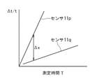
- It is a schematic diagram which shows. It is a flowchart explaining the outline of the virus inspection method which concerns on 3rd extended embodiment. It is a figure which shows the principle that the inspection time is shortened in the 3rd extended embodiment. It is a schematic diagram which shows the schematic structure of the nozzle of the virus inspection apparatus which concerns on 4th extended embodiment of this invention.
- FIG. 22 (a) is a schematic view showing the schematic structure of the detection container of the virus inspection apparatus according to the fifth extended embodiment of the present invention in a state where the detection substrate is removed
- FIG. 22 (b) is FIG. 22 (b). It is a schematic diagram explaining the position of a pseudo-receptor membrane by accommodating a detection substrate inside the detection container shown in a).
- FIG. 22 (c) is a schematic diagram illustrating a structure in which the height of the inner wall of the gas detour chamber of the detection container shown in FIG. 22 (a) is lowered. It is a schematic diagram which shows the schematic structure of the detection container of the virus inspection apparatus which concerns on the 6th extended embodiment of this invention.
- FIG. 26 (a) is a cross-sectional view as an exploded view schematically showing the structure of the inspection container main body of the virus inspection apparatus according to the sixth extended embodiment
- FIG. 26 (b) is a sectional view of FIG. 26 (a).
- It is sectional drawing which shows the structure of the susceptor part inserted in the lower part of the inspection container main body, and is the schematic diagram explaining the example of the mechanism for exchanging a sensor cell by attaching and detaching a susceptor part which becomes a part of a revolver.
- FIG. 28 It is a schematic diagram which shows the schematic structure of the 6-ball rotation movement mechanism (revolver) which automatically arranges a sensor cell in a detection container in the virus inspection apparatus which concerns on the 6th extended embodiment. It is a schematic diagram which shows the schematic structure of the virus inspection system which concerns on the 7th extended embodiment of this invention. It is a schematic diagram which shows the detail of the aerosol generator of the virus inspection apparatus which constitutes the virus inspection system shown in FIG. 28, and the structure around it. It is a flowchart explaining the outline of each step of the virus inspection method which concerns on 7th extended embodiment. It is a figure which shows the response curve of the virus sensor of the virus inspection apparatus which concerns on 7th extended embodiment.
- FIG. 35 (a) is a diagram showing in detail the state of the target virus and the non-specific adsorbed substance at the time of injecting the air to be inspected
- FIG. 35 (b) is a diagram showing the target virus and the non-specific adsorbed substance at the time of injecting the purge gas. It is a figure which showed the situation of a substance in detail.
- the basic and the first to eighth extended embodiments shown below are typical embodiments illustrating devices and methods for embodying the technical idea of the present invention, and are technical aspects of the present invention.
- the idea does not specify the material, shape, structure, arrangement, etc. of the components to the following.
- the technical idea of the present invention may be modified in various ways within the technical scope specified by the claims described in the claims. Further, the directions of "left and right” and “up and down” in the following description are merely definitions for convenience of explanation, and do not limit the technical idea of the present invention.
- the virus inspection system takes in and concentrates the detection substrate 11a having the pseudo-receptor membrane 13 coated at least partially and the air to be inspected 31a, and concentrates the air to be inspected.
- the virus transport pipe A that injects 31a onto the surface of the pseudoreceptor membrane 13 and the inspection function of the detection substrate 11a and the pseudoreceptor membrane 13, the surface of the pseudoreceptor membrane 13 is subjected to a spike protein receptor binding reaction. It is provided with a signal processing unit 50 that detects the presence of the target virus bound to the above by integral type difference. As schematically shown in FIG.
- the pseudoreceptor 14 has a structure that imitates a protein called immunoglobulin produced by B cells, and is similar to a host cell receptor (receptor) on the surface of a living cell. It has the function of recognizing a specific virus and specifically binding to the protrusion of the spike glycoprotein of the virus.
- FIG. 10B is a diagram illustrating a model in which the RBD of the spike glycoprotein 17 and the pseudoreceptor 14 bind to each other when the surface of the pseudoreceptor membrane 13 is covered with the liquid film 61. .. In contrast to FIG. 10 (b), FIG. 10 (b), FIG. 10 (b), FIG. 10 (b), FIG. 10 (b), FIG. 10 (b), FIG. 10 (b), FIG. 10 (b), FIG.
- FIG. 10 (a) shows a spike of the target virus 60 due to the action of the liquid contained in the aerosol 33b to be inspected in a state where the pseudo-receptor membrane 13 is not covered with the liquid film 61. It is a figure explaining the model which binds RBD of glycoprotein 17 and pseudo-receptor 14. Then, as in the case of biological cells, the reaction in which the RBD of the spike glycoprotein 17 of the target virus 60 and the pseudoreceptor 14 bind to form the spike protein receptor binding 19 is described in the present specification as a “specific binding reaction”. I will call it.
- FIG. 10 schematically illustrates the structure of a Y-shaped pseudoreceptor 14 that replicates the shape of a Y-shaped antibody in which a pair of H-chains and L-chains are bound.
- the host cell receptor on the surface of living cells mainly binds to the virus at the tip of the part where the H chain and L chain face each other (called the variable part), so the structure of only that part is basic. It is also sufficient to prepare it as the structure of the pseudo-receptor 14 of the virus inspection device according to the embodiment.
- the target virus 60 exemplified in FIG. 10 is the SARS-CoV-2 virus
- the RBD of the spike glycoprotein 17 binds to angiotensin converting enzyme 2 (ACE2 receptor) on the surface of human cells with high affinity. It is known to do.
- ACE2 receptor angiotensin converting enzyme 2
- the SARS-CoV-2 virus it is possible to adopt a structure that replicates the VHH antibody from which only the variable portion of the antibody composed of only the H chain is extracted, as the structure of the pseudoreceptor 14. ..
- the VHH antibody is obtained by cutting out a variable region portion of a characteristic antibody called a heavy chain antibody possessed by an alpaca or the like, and unlike a normal IgG type antibody, it binds to an antigen such as a virus with only a single chain.
- the virus inspection device constituting the virus inspection system is coupled in the middle of the virus transfer pipe A, and clean and moist air is quasi-received by the detection base 11a via the virus transfer pipe A.
- a purge gas transfer pipe D or the like in which the purge gas is supplied to the suction pump 40 via the virus transfer pipe A and the detection container 10 may be further provided, if necessary.
- the virus is contained in droplets, microdroplets (aerosol), droplet nuclei, etc. in the air to be inspected 31a.
- droplets are considered to be particles with a size of 5 ⁇ m or more
- microdroplets and droplet nuclei are considered to be particles with a size of 5 ⁇ m or less.
- the generic name is "aerosol”.
- the air to be inspected 31a of the virus inspection device according to the basic embodiment is the air to be inspected as the object to be inspected for the presence or absence of a virus, and is the air collected from a living space, a public building, or a transportation vehicle. , Or breath taken from the subject in breath analysis or breath diagnosis.
- the "clean and moist air” is air that does not contain impurity particles or viruses and that contains water that is the source of the reaction field of the specific binding reaction or vapor of a buffer solution that imitates the biological environment. Further, “dry air” is dry air that does not contain impurity particles or viruses.
- the detection substrate 11a corresponds to a homogeneous piezoelectric crystal sphere such as a crystal sphere.
- the ball SAW sensor 1003 used in the virus inspection apparatus according to the basic embodiment includes a detection base 11a, a signal converter 12 provided on the detection base 11a, a pseudo-receptor membrane 13, and the like. ..
- the detection substrate 11a can mount the pseudo-receptor membrane 13 on at least a part of the surface thereof, and the surface state of the pseudo-receptor membrane 13 changes, and a physical signal indicating a change in the surface state of the pseudo-receptor membrane 13 is transmitted.
- the substrate is not limited to the piezoelectric crystal sphere as long as it is a substrate on which the signal converter 12 that converts an electric signal can be mounted.
- the pseudoreceptor membrane 13 provided on at least a part of the surface of the piezoelectric crystal sphere as the detection substrate 11a is a pseudoreceptor that specifically binds to the virus.
- the ball SAW sensor 1003 of the virus inspection device includes a detection substrate 11a, a signal converter 12 provided on the detection substrate 11a, and a pseudo-receptor membrane 13, as shown in FIG. It is based on a structure having a pseudo-receptor 14 provided on the receptor membrane 13.
- the signal converter 12 provided in a predetermined region on the surface of the detection substrate 11a is a comb-shaped sensor electrode.
- the signal converter 12 converts an acoustic signal indicating a change in the mass of the pseudo-receptor membrane 13 due to the pseudo-receptor 14 provided on the pseudo-receptor membrane 13 specifically binding to the target virus into an electric signal. do.
- the signal processing unit 50 detects an integrated difference by using the increase in the weight area density of the pseudo-receptor membrane 13 due to the virus bound to the pseudo-receptor 14 as the delay time response of SAW.
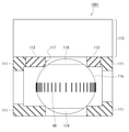
- the detection container 10 accommodating the detection base 11a houses the ball SAW sensor 1003 in a closed space so that the signal converter 12 can output an electric signal necessary for integral type difference detection. .. With the ball SAW sensor 1003 shown in FIG.
- the “detection cell 1000” of the virus inspection device is configured as shown in FIG. There is. Then, in the structure of the detection cell 1000 shown in FIG. 3, the air to be inspected 31a is introduced into the detection container 10, and a high-speed air flow enriched with the target virus is injected to the ball SAW sensor 1003 stored in the detection container 10. ing. That is, the detection container 10 provides an airtight space cut off from the outside for the signal converter 12 to convert an acoustic signal accompanying a change in physical state due to a target virus existing in the air to be inspected 31a into an electric signal. is doing.
- the detection container 10 for accommodating the ball SAW sensor 1003 has an introduction port 35a on one side (left side in FIG. 3) and an exhaust pipe 134 on the other side (right side in FIG. 3) facing the introduction port 35a.
- the end of the virus transport pipe A on the gas injection side is connected to the introduction port 35a of the detection container 10 from the left side of FIG.
- the suction pump 40 shown in FIG. 1 is connected to the exhaust pipe 134 of the detection container 10 on the right side of FIG.
- the detection container 10 is hollow, and the ball SAW sensor 1003 is arranged inside the detection container 10.
- the detection substrate 11a is spherical, and as shown in FIG. 2, a part or almost the entire surface of the detection substrate 11a is covered with the pseudo-receptor membrane 13.
- the detection substrate 11a as a three-dimensional substrate constituting the ball SAW sensor 1003 of the virus inspection device provides a homogeneous material ball in which a circular annular band for propagation of SAW is defined.
- the signal converter 12 composed of a comb-shaped sensor electrode repeats through a circular annular orbit defined on a piezoelectric sphere while passing through a sensitive film as a pseudo-receptor film 13 formed on the annular orbit. Generates a propagating SAW collimated beam.
- FIG. 2 schematically shows the wavefront 99 of surface acoustic waves constituting the collimated beam, which is a set of vertical lines along the equator of the detection substrate 11a. In the schematic structure illustrated in FIG.
- the pseudoreceptor membrane 13 can be formed on almost the entire surface of the annular zone defining the annular orbit on the three-dimensional substrate. Since the pseudoreceptor membrane 13 has a pseudoreceptor 14 that specifically binds to a specific virus, by selecting the structure of the pseudoreceptor 14, is the specific virus contained in the air to be inspected 31a? It can be inspected whether or not.
- Examples of the piezoelectric sphere constituting the detection substrate 11a of the virus inspection apparatus according to the basic embodiment include crystal, Langasite (La 3 Ga 5 SiO 14 ), lithium niobate (LiNbO 3 ), lithium tantalate (LiTaO 3 ), and the like. Crystal spheres such as piezoelectric ceramics (PZT) and bismus germanium oxide (Bi 12 GeO 20 ) can be used. As the underlying film of the pseudo-receptor film 13, a silica (SiO x ) film or the like can be used.
- a comb-shaped electrode (IDT) in which a chromium (Cr) film is patterned in a comb shape can be mounted as a signal converter 12 on such an underlying film.
- IDT comb-shaped electrode
- the orbital path of surface acoustic waves is limited to a specific orbital zone having a certain width, depending on the type of crystal material. The width of the orbital zone may be increased or decreased depending on the anisotropy of the crystal.
- the ball SAW sensor 1003 of the virus inspection device there is no diffraction loss when orbiting around the piezoelectric sphere forming the detection substrate 11a, and there is only propagation loss due to material attenuation.
- the collimated beam repeatedly passes through the pseudo-receptor membrane 13 configured to adsorb only the target virus contained in the air to be inspected 31a schematically surrounded by a broken line in FIG. 1. Since the target virus adsorbed on the pseudo-receptor 14 on the pseudo-receptor membrane 13 changes the propagation characteristics of SAW of the ball SAW sensor 1003, the change in the propagation characteristics due to the target virus adsorbed on the pseudo-receptor membrane 13 changes.
- the virus inspection apparatus it is integrated for each orbit of the SAW collimated beam through multiple orbits. Therefore, according to the virus inspection apparatus according to the basic embodiment, even if the number of target viruses contained in the air to be inspected 31a is very small, the target virus can be effectively detected in real time, so that the target virus can be detected. The accuracy of in situ inspection can be improved.
- the aerosol 33b to be inspected shown in the schematic diagram of FIG. 2 passes through the filter 30a of the crude aerosol 33a, and its size L2 depends on the function of the filter 30a.
- the size of the target virus 60 contained in the aerosol 33b to be inspected is usually several tens to several hundred nm.
- the size L1 of the detection substrate 11a is preferably 1 mm to 5 mm, for example, about 3 mm.
- the optimum size L1 of the detection substrate 11a can be determined according to the size of the inspection apparatus and the replacement frequency of the detection substrate 11a.
- a pseudo-receptor membrane 13 in which a plurality of pseudo-receptors 14 are arranged on the surface of the detection substrate 11a.
- an insoluble bead-like or membrane-like carrier is used.
- a method of chemically or physically binding a plurality of pseudoreceptors 14 can be adopted.
- a chemical bond a normal covalent bond or the like can be considered, and as a physical bond, a van der Waals force or the like can be considered.
- the carrier may be agarose, quartz or the like, and for example, an aldehyde group, an NHS group (N-hydroxysuccinimide group) or the like is immobilized on the surface of the carrier, and an amide bond is formed with an amino group in a plurality of pseudoacceptors 14. May be used. Further, a protein A or protein G or the like is fixed on the surface of the carrier, and a protein A or protein G or the like having a plurality of pseudoreceptors 14 affinity-bound may be used. When performing affinity binding, a cross-linking agent can be added to reinforce the affinity binding.
- a method of enclosing the carrier in a reticulated polymer compound can be adopted.
- a method of enclosing the carrier in a net crosslinked with polyvinyl alcohol (PVA) or the like can be adopted.
- the ball SAW sensor 1003 as shown in FIG. 2 can be realized by providing the pseudo-receptor film 13 on at least a part of the detection substrate 11a by using the network crosslinked with the PVA or the like as the pseudo-receptor film 13.
- the detection cell 1000 of the virus inspection device according to the basic embodiment as shown in FIG. 3 can be configured.
- the pseudo-receptor membrane 13 has a plurality of pseudo-receptors 14 which are organic substances arranged, sufficient care must be taken when storing the detection cell 1000 and the ball SAW sensor 1003.
- the pseudoreceptor 14 is a protein, it is necessary to store it under temperature conditions, pH conditions, and other environmental conditions in which the pseudoreceptor 14 is not denatured.
- temperature conditions depending on the type of pseudoreceptor 14, some may be denatured unless frozen (about -80 ° C), and may exist stably even in refrigeration (about 4 ° C) or at room temperature. Since there are some, it is necessary to carry out appropriate storage depending on the type of pseudoreceptor 14.
- a method of applying a stabilizer to the surface of the pseudoreceptor 14, a method of immersing the stabilizer in a liquid, and the like can be adopted.
- the stabilizer commonly used agents such as glycerol, trehalose and sucrose can be adopted.
- the pseudo-receptor 14 is usually masked, masked only when it is used, the pseudo-receptor 14 is activated, and when it is not used, it is re-masked. ..
- the pseudo-receptor 14 is protected by masking with something like a pseudo-antigen, and when the detection cell 1000 or the ball SAW sensor 1003 is used, the pseudo-antigen is separated with an acid / alkali, a buffer solution, or the like. May be good.
- the used detection cell 1000 and ball SAW sensor 1003 can be reused by removing impurities other than the target virus bound to the pseudoreceptor 14 and the target virus attached to the pseudoreceptor membrane 13 and other parts. can do. In this case, it is preferable to sterilize the used detection substrate 11a and then reuse it.
- As the sterilization treatment a sterilization / sterilization method using heating, acid / alkali, high-concentration alcohol, ultraviolet rays, a surfactant and the like can be adopted. However, it is a condition that the pseudoreceptor 14, which is a protein, is not denatured in the sterilization process. Further, it is preferable to sterilize the virus transport pipe A through which the target virus may pass, the inside of the detection container 10, the suction pump 40, etc. as necessary. A strong sterilization method or cleaning method that the detection container 10 can withstand can be adopted.
- the method of taking out the used detection substrate 11a from the detection container 10 and regenerating it has been described, but the activity of the pseudo-receptor 14 is restored with the detection substrate 11a placed in the detection container 10.
- a mechanism For example, by providing a sterilization mechanism in the detection container 10, a target virus bound to the pseudoreceptor 14 by a spike protein receptor binding 19 at an initial stage of executing a virus inspection method or an inspection program described later, or It is also possible to remove impurities other than the target virus adhering to the pseudo-receptor membrane 13 and other parts.
- the virus transport pipe A of the virus inspection device includes a filter 30a, an on-off valve 32, and a common concentration mechanism 34.
- the filter 30a has a function of removing aerosols (0.1 to 30 ⁇ m) contained in the air to be inspected 31a exceeding a predetermined size (for example, 4 ⁇ m), and has a function of removing the aerosol (for example, 4 ⁇ m) on the introduction port side of the virus transport pipe A. It is provided in.
- This predetermined size varies depending on the type of virus, and also depending on whether it is due to airborne infection, aerosol infection, or droplet infection.
- the humid air transport pipe B of the virus inspection device is coupled to the virus transport pipe A in the middle, specifically, between the on-off valve 32 and the common concentration mechanism 34, and the filter 21 and the mass flow controller ( It includes an MFC) 22, a humidifier 20, a humidifying input valve 23a, and a humidifying output valve 23b.
- the humidification input valve 23a and the humidification output valve 23b are composed of a three-way valve, and the humidifier 2 is composed of a nebulizer (liquid atomizer) for generating water, a permeation tube, and the like.
- the filter 21 contains activated carbon and the like, and has a function of generating clean and dry air by removing impurities and moisture contained in the environmental air.
- the environmental air is preferably air collected from a space different from the examination room or from the outside air, but is not particularly limited, and may be collected from the same space as the examination room.
- the humidifier 20 has a function of impregnating clean and dry air with the vapor of a liquid used for a specific binding reaction to generate clean and dry air.
- the dry air transport pipe C of the virus inspection device according to the basic embodiment is a route that has passed the route from the moist air transport pipe B to the humidifier 20.
- the purge gas transfer pipe D of the virus inspection device according to the basic embodiment is in the middle of the virus transfer pipe A, is connected between the filter 30a and the on-off valve 32, and includes a gas supply unit 70.
- the gas supply unit 70 selectively supplies the sterilizing gas or the purge gas to the virus transport pipe A via the purge gas transport pipe D.
- the disinfectant gas is, for example, for removing a virus or the like adhering to the inside of the pipe or the device from the virus transport pipe A to the suction pump 40 after inspecting for the presence or absence of a virus in the air.
- the purge gas is for removing non-specific adsorbed substances other than the target virus adsorbed on the surface of the detection substrate 11a.
- the gas remaining in the pipes and equipment is removed before the sterilizing gas is supplied, and the gas in the pipes and equipment is checked before checking the humidity in the pipes and equipment by driving the humidifier 20. Is for removing in advance.
- the aerosol from the filter 30a changes to the aerosol 33b to be inspected, which is a hydrous aerosol mixed with the clean and moist air from the humidifier 20.
- the common concentration mechanism 34 schematically shown by a triangle in FIG. 1 can form a tapered injection nozzle as illustrated in FIG. 11 (a) or FIG. 11 (b). It is not necessary to limit the structure to the structure shown in 11 (a) or 11 (b), and various structures can be adopted as long as the structure includes a tapered tapered shape.
- the group of the aerosol to be inspected 33b composed of the hydrous aerosol becomes denser, and the number volume density of the target virus contained in the aerosol to be inspected 33b becomes more concentrated.
- a group of aerosols 33b to be inspected ejected from the common concentration mechanism 34 is sucked by a suction pump 40 connected to the detection container 10 to form a high-speed air flow from the common concentration mechanism 34 into the inside of the detection container 10. It is sprayed.
- the group of aerosols to be inspected 33b is ejected onto the pseudoreceptor membrane 13 that is placed on this high-speed airflow and covers at least a part of the detection substrate 11a.
- 11B has a double structure having a sheath flow F having a collimation focus action so as to surround the main flow through which a group of aerosols 33b to be inspected flows.
- the sheath flow F is clean air, and when it flows, it encloses the aerosol jet inside the sheath flow F, and the aerosol jet does not spread, and the yield is high, and the surface of the pseudo-receptor membrane 13 of the ball SAW sensor 1003 is present.
- a group of aerosols to be inspected 33b consisting of hydrous aerosols can be collected.
- the signal processing unit 50 of the virus inspection system controls the operations of the detection container 10, the humidifier 20, the mass flow controller 22, the suction pump 40, and the gas supply unit 70 shown in FIG. .. Further, the signal processing unit 50 controls the opening and closing of the on-off valve 32 and the operation of the humidifying input valve 23a and the humidifying output valve 23b.
- the clean and dry air that has passed through the filter 21 is supplied to the humidifier 20 after the flow rate is adjusted by the mass flow controller 22, or forms a tapered shape with the on-off valve 32 via the dry air transport pipe C. It is supplied to the virus transport pipe A between the common concentration mechanism 34.
- the clean and moist air from the humidifier 20 is supplied to the virus transport pipe A between the on-off valve 32 and the common concentration mechanism 34.
- the wet air transfer pipe B and the dry air transfer pipe C are selectively selected by the signal processing unit 50.
- the detection container 10 constituting the detection cell 1000 of the virus inspection device is connected to a common concentration mechanism 34 for concentrating the number volume density of a group of aerosols 33b to be inspected composed of hydrous aerosols.
- the introduction port 35a is provided on one side.
- the detection container 10 constituting the detection cell 1000 is composed of a metal box portion 123 having an open ceiling portion and a metal lid portion 121 closing the upper portion (ceiling portion) of the box portion 123 to form a rectangular parallelepiped closed container. is doing.
- An O-ring groove 132a is engraved on the upper end of the box portion 123 as a U-shaped groove so as to go around the upper part of the box portion 123 in order to form a closed container, and an O-ring 131a is engraved on the O-ring groove 132a. It is stored.
- the O-ring groove 133a is engraved as a U-shaped groove on the lower surface of the lid portion 121.
- An exhaust pipe 134 is provided on the other side (right side in FIG. 3) facing the introduction port 35a of the box portion 123, and an orifice 9 is provided inside the exhaust pipe 134.
- the common enrichment mechanism 34 and the introduction port 35a connected to the common enrichment mechanism 34 form a part of the virus transport pipe A schematically (conceptually) shown in FIG. 1 and pass through the filter 30a of FIG. A group of aerosols 33b to be inspected is ejected as a high-speed airflow toward the pseudo-receptor membrane 13 of the ball SAW sensor 1003 housed in the detection container 10.
- the common concentration mechanism 34 constitutes a high-speed air flow toward the pseudo-receptor membrane 13 by the shape of the injection nozzle as a tapered hole provided inside the first path end portion 124a which is the end portion of the virus transport pipe A. ..
- the common concentration mechanism 34 of the first path end portion 124a and the introduction port 35a of the box portion 123 are airtightly connected by using an O-ring 131b. Therefore, an O-ring groove 132b is engraved on the left side of the box portion 123 as a U-shaped groove so as to go around the introduction port 35a, and the O-ring 131b is housed in the O-ring groove 132b.
- the O-ring groove 133b is engraved as a U-shaped groove on the right side of the first path end portion 124a.
- the ball SAW sensor 1003 is housed inside the susceptor 1001 with a handle shown in FIGS. 4 to 6 with the north pole-south pole orientation adjusted.
- the susceptor 1001 with a handle includes a frame portion 111, a frame cap 112 provided on the upper surface of the ram portion 111, a handle 113 for holding the frame portion 111, and the like.
- the frame portion 111 of the susceptor 1001 with a handle is a cubic or rectangular parallelepiped resin skeleton frame capable of accommodating the ball SAW sensor 1003. As shown in the upper left portion of FIG.
- a handle 113 serving as a holding portion at the time of replacement has an integrated structure continuous with the frame portion 111. It is provided. As can be seen from FIGS. 4 and 6, the handle 113 has a plate-like structure. As shown in FIG. 4, a frame cap 112 that allows the upper portion of the frame portion 111 to be released is provided on the upper surface of the frame portion 111 so as to be removable. In the center of the frame cap 112, an upper electrical contact hole 117 for making electrical contact with the north pole electrode 118 at the north pole of the ball SAW sensor 1003 is provided.
- a lower electrical contact hole for making electrical contact with the Antarctic electrode 119 at the South Pole of the ball SAW sensor 1003 is provided in the center of the lower surface of the frame portion 111. Since the lower electrical contact holes provided on the Antarctic side and the lower surface are in contact with each other, the lower electrical contact holes provided on the lower surface are not positively shown. Since the detection substrate 11a is spherical, the lower electrical contact hole in the center of the lower surface of the susceptor 1001 with a handle arranges the detection substrate 11a so that the detection substrate 11a does not roll, similarly to the upper electrical contact hole 117. It is a circular opening for.
- the ball SAW sensor 1003 is inserted into the susceptor 1001 with a handle by precisely aligning the north pole electrode 118, the south pole electrode 119, and the equatorial plane of the detection substrate 11a in advance, and makes an upper electrical contact. It is fixed by the edge of the hole 117 and the edge of the lower electrical contact hole. Since the lid portion 121 of the detection container 10 shown in FIG. 4 has a structure that can be easily removed from the box portion 123, the frame portion is framed from the upper part of the box portion 123 by removing the lid portion 121 from the box portion 123. The unit 111 can be easily taken in and out.
- the north pole electrode 118, the south pole electrode 119, and the equatorial plane of the ball SAW sensor 1003 are required to be precisely aligned.
- an assembled structure in which the ball SAW sensor 1003 is precisely aligned and adjusted inside the frame portion 111 is prepared in advance (at the time of shipment from the factory) as a susceptor 1001 with a handle. It can be solved by keeping it. That is, if the susceptor 1001 with a handle is prepared in advance, even if the user of the virus inspection device according to the basic embodiment does not have the skill of alignment adjustment, the ball SAW sensor 1003 can be taken in and out of the detection container 10.
- the detection cell 1000 can be easily assembled.
- the set of the susceptor 1001 with a handle and the ball SAW sensor 1003 housed in the susceptor 1001 with a handle is shipped from the factory as a product of the "sensor unit" so that the user can assemble the detection cell 1000. do it.
- a U-shaped alignment groove is dug in the lower surface of the lid portion 121 in accordance with the position of the handle 113.
- the aerosol ejected from the introduction port 35a is ejected by fitting the upper end portion of the handle 113 into the alignment groove.
- the alignment of the jet and the pseudo-receptor membrane 13 can also be easily performed.
- the susceptor 1001 with a handle shown in FIGS. 4 to 6 can also be used during processes such as formation and regeneration of the pseudoreceptor membrane 13, and also plays a role of facilitating the handling of the detection substrate 11a during the process.
- an electrode holder 122 made of an insulator is arranged in the center of the lid portion 121 of the detection container 10 of the virus inspection device according to the basic embodiment, and the center of the electrode holder 122 is a rod-shaped external electrode.
- 105 penetrates vertically.
- the lower tip of the external electrode 105 is electrically connected to the arctic electrode 118 via the upper electrical contact hole 117.
- the metal box portion 123 is set to the ground potential.
- a central protrusion at the bottom of the box 123 is electrically connected to the Antarctic electrode 119 via a lower electrical contact hole provided in the center of the lower surface of the frame 111.
- a Pelche element or a thermistor may be incorporated in the box portion 123.
- the Pelche element is used to heat and cool the detection substrate 11a, and the thermistor can be replaced with another temperature sensor such as a thermocouple and can be used to adjust the temperature of the detection substrate 11a.
- the O-ring 131a as a sealing member is arranged between the upper part of the box portion 123 and the lid portion 121, in order to replace the sensor unit, for the replacement of the susceptor 1001 with a handle. It has a removable structure. Therefore, the structure using the O-ring 131a secures an airtight seal that prevents gas from leaking after the work of putting in and taking out the susceptor 1001 with a handle.
- the conceptual configuration of the virus inspection device constituting the virus inspection system according to the basic embodiment shown in FIG. 1 is a specific configuration according to the first modification as shown in FIG. 7, and can be realized more simply and compactly. be. That is, in FIG. 1, the routes of the virus transfer pipe A, the wet air transfer pipe B, and the dry air transfer pipe C are selectively selected by controlling the operation of the on-off valve 32, the humidification input valve 23a, and the humidification output valve 23b. However, if the specific configuration of the virus inspection device according to the first modification shown in FIG. 7 is used, the virus transfer pipe A can be effectively used without using the on-off valve 32, the humidification input valve 23a, and the humidification output valve 23b.
- the route of the wet air transfer pipe B and the dry air transfer pipe C can be switched.
- the entire structure in which the susceptor 1001 with a handle is housed inside the closed container composed of the box portion 123 and the lid portion 121 shown in FIG. 3 is "a housing". It is simplified and shown as "1a”.
- reference numeral 1003 of the ball SAW sensor 1003 shown in FIG. 2 is omitted for convenience.
- the reference numeral 1000 of the detection cell 1000 shown in FIG. 3 is also omitted. Due to the omission of reference numerals 1003 and 1000 in the corresponding drawings, in the description of FIG.
- the common concentration mechanism 34 of the first path end portion 124a and the introduction port 35a of the box portion 123 are described as a structure in which they are airtightly connected by using an O-ring 131b.
- the first enrichment mechanism (virus enrichment mechanism) 34a of the path end portion 124a and the introduction port 35a of the housing 1a are read as a structure in which they are airtightly connected by using an O-ring 131b.
- the first enrichment mechanism 34a is a dedicated enrichment mechanism specialized for the purpose of compressing into a high-speed airflow of an aerosol containing a target virus and injecting the high-speed airflow enriched with the target virus onto the pseudoreceptor membrane 13.
- the central axis along the injection direction of the first path end portion 124a has a radial relationship with the central axis.
- the second path end 124b and the third path end 124c having an axis are arranged. That is, at the center of the broken line circle surrounding the housing 1a in FIG. 7, three types of high-speed airflow injection directions from the first path end portion 124a, the second path end portion 124b, and the third path end portion 124c intersect.
- the first path end portion 124a injects the air to be inspected 31a into the pseudo-receptor membrane 13 of the ball SAW sensor (11a, 12, 13) via the first concentration mechanism 34a provided at the tip (exit side).
- the purpose is to do things.
- the first path end portion 124a is independent of the housing 1a and can be connected / disconnected from the housing 1a via the O-ring 131b. That is, the first path end portion 124a is connected to the second path end portion 124b or the third path end portion 124c by rotating relatively along the outer circumference of the broken line circle surrounding the housing 1a in FIG. 7. Can be exchanged.
- “Relative rotation” means that the central housing 1a may rotate, and conversely, the central housing 1a is fixed, and the first path end portion 124a, the second path end portion 124b, and the third path path 3 are fixed.
- the turntable with the end 124c may rotate.
- the second path end portion 124b is provided with a second concentration mechanism (dry air concentration mechanism) 34b having a tapered tapered shape for exclusive use, and further, the second path end portion 124b.
- the connection pipe 135b is connected in an airtight structure without leakage so as to provide a drying chamber 2c having a dryer on the input side of 124b.
- the second concentration mechanism 34b of the second path end portion 124b and the introduction port 35a of the housing 1a are O-rings 131c. Is airtightly connected using.
- the second path end portion 124b supplies clean and dry air onto the surface of the pseudo-receptor film 13 of the ball SAW sensor (11a, 12, 13) and adheres to the inner wall of the housing 1a and the surface of the detection substrate 11a.
- the purpose is to perform a purging step for removing non-specific adsorbed substances as impurities.
- the third path end portion 124c is provided with a dedicated third concentration mechanism (humidified air concentration mechanism) 34c having a tapered tapered shape, and a nebulizer (liquid atomization) is provided on the input side of the third path end portion 124c.
- the connection pipe 135c is connected in an airtight structure without leakage so as to provide a humidifying chamber 2c having a humidifier such as an apparatus).
- a third filter 30c is connected to the input side of the humidifying chamber 2c in an airtight structure without leakage.
- the third filter 30c corresponds to, for example, the filter 21 of FIG. 1, and takes in air from the outside, removes impurities of a predetermined size or larger, and removes excess water to obtain clean and dry air. In the humidifying chamber 2c, a predetermined amount of water is contained in the clean and dry air from the third filter 30c.
- the clean humid air is brought into the ball SAW sensor (11a) by the third concentration mechanism 34c. , 12, 13) can be sprayed onto the surface of the pseudoreceptor membrane 13 to perform the humidification step.
- the second filter 30b may also be connected to the input side of the drying chamber 2c on the second path end portion 124b side in an airtight structure without leakage.
- clean and dry air is supplied onto the surface of the pseudo-receptor film 13 of the ball SAW sensor (11a, 12, 13) and adheres to the inner wall of the housing 1a and the surface of the detection substrate 11a.
- a purging step can be performed to remove the non-specific adsorbed substance as an impurity.
- the second filter 30b corresponds to, for example, the filter 21 of FIG. 1, and can take in air from the outside, remove impurities of a predetermined size or larger, and remove excess water to obtain clean and dry air.
- the drying chamber 2c further dries the clean and dry air from the third filter 30c, but the drying chamber 2c can be omitted if sufficient clean and dry air can be generated by the third filter 30c.
- a filter corresponding to the filter 30a in FIG. 1 may be provided on the input side of the first path end portion 124a.
- a humidifying chamber having a humidifier such as a nebulizer (liquid atomizer) between the first path end portion 124a and the filter corresponding to the filter 30a is provided with a leak-free airtight structure.
- a humidifier such as a nebulizer (liquid atomizer) between the first path end portion 124a and the filter corresponding to the filter 30a
- a leak-free airtight structure According to the virus inspection device according to the basic embodiment shown in FIG. 7, which may be connected, three types of dedicated nozzles, a first concentration mechanism 34a, a second concentration mechanism 34b, and a third concentration mechanism 34c, are prepared for each purpose. ing.
- the piping, the on-off valve 32, the humidification input valve 23a, the humidification output valve 23b, and the like as shown in FIG. 1 are not used.
- the aerosol 33b to be inspected sucked at the shortest distance can be delivered to the ball SAW sensor (11a, 12, 13), the inner wall of the housing 1a, or the like.
- the shape and configuration of the first concentration mechanism 34a, the second concentration mechanism 34b and the third concentration mechanism 34c are obtained according to the purpose. It is also possible to adjust the jet of the aerosol 33b to be inspected, the flow velocity of the air flow, and the like by changing the above. Further, these steps are performed by performing a humidification step at the third path end portion 124c, performing a suction / inspection step at the first path end portion 124a, and then switching to the second path end portion 124b and performing a purging step. It can be done continuously.
- a fourth unit for generating alcohol vapor is added, and the gas injected from the nozzle (fourth concentration mechanism) of the fourth unit is used to detect cells (11a, 12, It is also possible to clean and sterilize the inner walls of the ball SAW sensors (11a, 12, 13) constituting 13, 1a) and the housing 1a. According to the virus inspection device according to the basic embodiment, there is an advantage that the cleaning and sterilization steps can be performed without adding new pipes and valves.
- FIG. 7 Although the configuration of rotational movement is illustrated in the virus inspection device according to the first modification of the basic embodiment of FIG. 7, translational movement (parallel movement) of the virus inspection device according to the second modification of the basic embodiment as shown in FIG. 8 is illustrated. Even with the configuration of (movement), a simple and compact virus inspection device can be realized as in FIG. 7.
- FIG. 8 as in FIG. 7, the entire structure in which the susceptor 1001 with a handle is housed inside the closed container composed of the box portion 123 and the lid portion 121 shown in FIG. 3 is simplified and displayed as “housing 1b”. is doing. Similar to FIG. 7, in the simplified display of FIG.
- the first concentration mechanism 34a of the first path end portion 124a and the introduction port 35a of the housing 1b correspond to a structure in which the introduction port 35a of the housing 1b is airtightly connected by using an O-ring 131b.
- the surface of the housing 1a on the first enrichment mechanism 34a side of FIG. 7 was a curved surface
- the surface of the housing 1b of FIG. 8 on the virus concentration mechanism (first concentration mechanism) 34u side was flat. It's different.
- the first path end portion 124u moves in translation relative to the housing 1b of FIG. 8 along a direction orthogonal to the gas injection direction.
- connection relationship can be exchanged with the second path end portion 124v or the third path end portion 124w.
- “Relative translational movement” means that the housing 1b on the right side may be translated, and conversely, the housing 1b is fixed, and the first path end portion 124u, the second path end portion 124v, and the second path end portion 124v on the left side are fixed.
- the translational moving board equipped with the three-path end portion 124w may be translated.
- the first has a central axis parallel to the central axis along the injection direction of the first path end portion 124u.
- the two-path end portion 124v and the third path end portion 124w are arranged. That is, the injection directions of the three types of high-speed airflow from the first path end portion 124u, the second path end portion 124v, and the third path end portion 124w are parallel.
- the second path end portion 124v is provided with a tapered dry air concentration mechanism (second concentration mechanism) 34v, similarly to the virus concentration mechanism (first concentration mechanism) 34u of the first path end portion 124u.
- connection pipe 135v is connected to the input side of the second path end portion 124v in an airtight structure without leakage so as to provide a drying chamber 2v having a dryer.
- the dry air concentrating mechanism 34v at the end of the second path 124v and the introduction port of the housing 1b are airtightly connected using the O-ring 131v.
- the second path end portion 124v supplies clean dry air as a purge gas onto the surface of the pseudo-receptor membrane 13 of the ball SAW sensor (11a, 12, 13), and on the inner wall of the housing 1b or the surface of the detection substrate 11b.
- a purging step is performed in which non-specific adsorbed substances as impurities adhering to the membrane are removed with clean dry air.
- a tapered moist air concentrating mechanism (third concentrating mechanism) 34w is provided at the end of the third path 124w, and a nebulizer (liquid atomizer or the like) is humidified on the input side of the end of the third path 124w.
- the connection pipe 135w is connected in an airtight structure without leakage so as to provide a humidifying chamber 2w having a vessel.
- the moist air concentrating mechanism 34w at the end of the third path 124w and the introduction port of the housing 1b are airtightly connected using the O-ring 131w.
- a third filter 30w is connected to the input side of the humidifying chamber 2w in an airtight structure without leakage.
- the third filter 30w corresponds to, for example, the filter 21 of FIG. 1, and takes in air from the outside, removes impurities of a predetermined size or larger, and removes excess water to obtain clean and dry air.
- a predetermined amount of water is contained in the clean and dry air from the third filter 30w. Therefore, by airtightly coupling the third path end portion 124w to the housing 1b, the clean moist air is brought into the pseudo-receptor of the ball SAW sensor (11a, 12, 13) by the moist air concentrating mechanism (third concentrating mechanism) 34w.
- the humidification step can be performed by injecting the film onto the surface of the film 13.
- the second filter 30v may also be connected to the input side of the drying chamber 2v on the second path end 124v side in an airtight structure without leakage.
- clean and dry air is supplied onto the surface of the pseudo-receptor film 13 of the ball SAW sensor (11a, 12, 13) and adheres to the inner wall of the housing 1b and the surface of the detection substrate 11b.
- a purging step can be performed to remove the non-specific adsorbed substance as an impurity.
- the second filter 30v corresponds to, for example, the filter 21 of FIG. 1, and can take in air from the outside, remove impurities of a predetermined size or larger, and remove excess water to obtain clean and dry air.
- the drying chamber 2v further dries the clean and dry air from the second filter 30v, but the drying chamber 2v can be omitted if sufficient clean and dry air can be generated by the third filter 30w.
- a filter corresponding to the filter 30a of FIG. 1 may be provided on the input side of the first path end portion 124u. be. Further, in order to inject the aerosol 33b to be inspected, a humidifying chamber having a humidifier such as a nebulizer (liquid atomizer) between the first path end portion 124u and the filter corresponding to the filter 30a is provided with a leak-free airtight structure. You may connect.
- a humidifier such as a nebulizer (liquid atomizer)
- the virus concentration mechanism (first concentration mechanism 34u, dry air concentration mechanism (second concentration mechanism) 34v) and moist air concentration mechanism (1st concentration mechanism 34u, dry air concentration mechanism (second concentration mechanism) 34v) according to the purpose.
- Third type of concentration mechanism) 34w three types of nozzles are prepared. Therefore, according to the virus inspection device according to the second modification shown in FIG. 8, a high-speed airflow is generated, and three types of high-speed airflows for different purposes are generated. For this reason, the virus to be inspected 33b sucked at the shortest distance without using the piping, on-off valve 32, humidification input valve 23a, humidification output valve 23b, etc. as shown in FIG. Etc. can be delivered to the ball SAW sensor (11a, 12, 13), the inner wall of the housing 1b, and the like.
- the first enrichment mechanism 34u, the second enrichment mechanism 34v, and the third enrichment mechanism 34w are provided according to the purpose. It is also possible to adjust the flow velocity of the jet and air flow of the aerosol 33b to be inspected by changing the shape and configuration. Further, the humidification step is performed at the third path end portion 124w, the suction / inspection step is performed at the first path end portion 124u, and then the procedure of switching to the second path end portion 124v and performing the purging step is continuously performed. Can be done.
- a fourth unit that generates alcohol vapor is added, and a ball SAW sensor (11a, 12, 13) or a housing is used by using the gas injected from the nozzle of the fourth unit. It is also possible to clean and sterilize the inner wall of 1b.
- the virus inspection device according to the second modification of the basic embodiment shown in FIG. 8 has a translational movement type configuration, but since it is equipped with three types of dedicated nozzles and an independent gas piping system, the rotation movement type shown in FIG. Similar to the virus inspection device of Nozzle, the cleaning and sterilization steps can be performed without adding new piping or valves.
- the signal processing unit 50 of the virus inspection system includes a data processor 500, a signal generator / receiver drive means (logic circuit) 510, a data storage device 511, and a program storage.
- a device 512, an output device 513, and a bus 514 connecting them are provided.
- the signal generator / receiver driving means 510 is a hardware resource such as an electronic circuit that controls and drives the operation of the signal converter 12 of the detection substrate 11a.
- the signal generator / receiver driving means 510 transmits an excitation burst signal to the signal converter 12 of the detection substrate 11a, and generates a collimated beam of SAW in the signal converter 12.
- the signal converter 12 receives an electric signal from the signal generator / receiver driving means 510, generates a SAW collimated beam which is an acoustic signal by electric-acoustic conversion, and detects the SAW collimated beam around the detection substrate 11a. Propagate. Further, the signal generator / receiver driving means 510 transmits a drive / control signal to the signal converter 12, and causes the signal converter 12 to receive an acoustic signal which is a collimated beam of SAW.
- the acoustic signal propagated while the SAW collimated beam rotates around the detection substrate 11a a predetermined number of times is acoustically-electrically converted by the signal converter 12 and converted into an electric signal.
- the signal generator / receiver driving means 510 receives the electric signal output by the signal converter 12 from the signal converter 12 as a feedback burst signal of the collimated beam, and stores it in the data storage device 511. After that, the signal generator / receiver driving means 510 reads the waveform data of the feedback burst signal from the data storage device 511 and sends it to the data processor 500.
- a mode is also possible in which the signal generator / receiver driving means 510 receives the feedback burst signal and then transmits it to the data processor 500 as it is without storing it in the data storage device 511.
- the weight of the pseudo-receptor membrane 13 changes as a physical state, and the propagation characteristics of SAW change.
- the sensor electrodes constituting the signal converter 12 acoustically-electrically convert an acoustic signal indicating a change in the physical state of the pseudo-receptor film 13 into an electric signal. ..
- the signal processing unit 50 executes an arithmetic logic operation using the acoustic-electrically converted electric signal, and measures the attenuation coefficient of SAW and the delay time of SAW.
- the data processor 500 constituting the signal processing unit 50 of the virus inspection system includes a humidifying means (logic circuit) 501, an injection means (logic circuit) 502, an inspection means (logic circuit) 503, and a valve control.
- the arithmetic sequence control means (logic circuit) 520 is provided as a logical hardware resource.
- the humidifying means 501 of the data processor 500 has the humidifier 20, the mass flow controller 22, and the suction pump 40 in a state where the on-off valve 32 is closed and the moist air transport pipe B is selected by the humidifying input valve 23a and the humidifying output valve 23b. Is activated to inject clean humid air onto the pseudo-receptor film 13 that covers at least a part of the detection substrate 11a. As a result, the liquid vapor used for the specific binding reaction is supplied to the pseudo-receptor membrane 13, and dew condensation occurs on the pseudo-receptor membrane 13, so that a liquid membrane is formed on the surface of the pseudo-receptor membrane 13. It will be.
- the injection means 502 of the data processor 500 logically transmits a command necessary to the valve control means 504 in order to control the on-off valve 32, the humidification input valve 23a, and the humidification output valve 23b.
- Hardware resource In a state where the on-off valve 32 is opened via the valve control means 504 and the moist air transfer pipe B is selected by the humidifying input valve 23a and the humidifying output valve 23b, the injection means 502 further includes the humidifier 20, the mass flow controller 22, and the humidifying device 22. And a command to start the suction pump 40 is transmitted.
- the injection means 502 forms a desired high-speed air flow of the aerosol 33b to be inspected, and causes the fluid flow of the aerosol 33b to be inspected to flow through at least one of the detection substrates 11a via the first concentration mechanism 34a.
- the operation of injecting the pseudo-receptor membrane 13 covering the portion as a high-speed airflow is controlled.
- a command for controlling the relative rotational movement of the housing 1a is transmitted to the sensor exchange means 508, and in the second modification illustrated in FIG. 8, a command for controlling the relative translational movement of the housing 1b is transmitted. do.
- the relative rotational movement of the housing 1a or the relative translational movement of the housing 1b is controlled via the sensor exchange means 508.
- the high-speed airflow of the aerosol 33b to be inspected is jetted onto the pseudo-receptor membrane 13, and on the surface of the pseudo-receptor membrane 13, the RBD of the spike glycoprotein 17 of the target virus 60 as shown in FIG.
- the specific binding reaction that binds to the body 14 to form the spike protein receptor binding 19 is accelerated.
- the inspection means 503 of the data processor 500 uses the waveform data of the feedback burst signal, which is an electric signal received by the signal generator / receiver (logic circuit) 510 from the signal converter 12, to perform arithmetic for integrated difference detection. It is a hardware resource that executes logic operations. That is, the inspection means 503 uses the feedback burst signal to detect the increase in the weight area density due to the target virus 60 bound to the pseudoreceptor 14 by the spike protein receptor binding 19 as an integral difference detection as the delay time response of SAW. By integrating the difference detection of the increase in the weight surface density as the delay time response of the SAW, the inspection means 503 can inspect the presence or absence of the target virus 60 in the air to be inspected 31a.
- the inspection means 503 receives a signal generator / receiver command from the signal converter 12 to cause the signal generator / receiver drive means (logic circuit) 510 to receive an electric signal indicating information on the delay time response of the SAW. It is transmitted to the device driving means 510.
- the signal generator / receiver driving means 510 Upon receiving the command, the signal generator / receiver driving means 510 receives the electric signal indicating the information of the delay time response from the signal converter 12 and stores it in the data storage device 511.
- the inspection means 503 reads an electric signal indicating the delay time response information from the data storage device 511 or directly receives the signal generator / receiver drive means 510, and integrates the obtained delay time response information. Perform the arithmetic and logical operations required to detect type differences.
- the inspection means 503 can easily, quickly, and highly sensitively check the presence or absence of the target virus in the air 31a to be inspected by executing the arithmetic logical operation of the integral type difference detection. Can be inspected.
- the inspection means 503 of the data processor 500 of the virus inspection system sends a command to the valve control means 504 to close the on-off valve 32, and further, the humidification input valve 23a and the humidification output valve 23b.
- the dry air transfer pipe C is selected by controlling the flow path. With the valve control means 504 selecting the dry air transfer pipe C, the inspection means 503 sends a command to the mass flow controller 22 and the suction pump 40 to activate each of the mass flow controller 22 and the suction pump 40 to clean and dry air. The operation of injecting onto the pseudo-receptor film 13 is realized.
- the inspection means 503 sprays clean dry air onto the pseudo-receptor membrane 13 after injecting the fluid flow of the aerosol 33b to be inspected onto the pseudo-receptor membrane 13 and before inspecting for the presence or absence of the target virus.
- Send a command to inject By issuing a command to dry the surface of the inspection means 503 and the detection substrate 11a, impurities (viruses or particles) other than the target virus bound to the pseudoreceptor 14 can be blown off and removed from the pseudoreceptor membrane 13. It will be possible, and moreover, highly sensitive in-situ inspection will be possible.
- the valve control means 504 of the data processor 500 controls the opening and closing of the on-off valve 32 and the detailed operation of the humidifying input valve 23a and the humidifying output valve 23b.
- the sterilizing gas control means 505 transmits a command necessary for controlling the operation of the gas supply unit 70 to the gas supply unit 70, and supplies the sterilizing gas from the gas supply unit 70 to the virus transport pipe A.
- the purge gas control means 506 transmits a command necessary for controlling the operation of the gas supply unit 70 to the gas supply unit 70, and supplies the purge gas from the gas supply unit 70 to the virus transport pipe A.
- the gas line inspection means 507 periodically inspects the virus transport pipe A, the wet air transport pipe B, the dry air transport pipe C, and the purge gas transport pipe D.
- the sensor exchange means 508 controls the rotational operation of the first deformation mode described with reference to FIG. 7 and the translational movement of the second deformation mode described with reference to FIG.
- the arithmetic sequence control means 520 is a humidification means 501, an injection means 502, an inspection means 503, a valve control means 504, a disinfectant gas control means 505, a purge gas control means 506, a gas line inspection means 507, and a sensor replacement means 508, respectively. Controls the sequence of actions of.
- Such a data processor 500 is preferably a chip such as a central processing unit (CPU) and can be incorporated inside the virus inspection device of the basic embodiment, but a personal computer (PC). ) Etc., which may be a part of the CPU in a general-purpose computer system.
- the data processor 500 can configure a computer system using a microprocessor (MPU) or the like mounted as a microchip.
- MPU microprocessor
- a digital signal processor (DSP) specialized in signal processing with enhanced arithmetic calculation function, and a microcontroller equipped with memory and peripheral circuits for the purpose of controlling embedded devices. (Microcomputer) or the like may be used.
- the data storage device 511 can be configured as a memory element such as a memory block included in a part of the logical blocks constituting the PLD.
- the data processor 500 may have a structure in which a CPU core-like array and a PLD-like programmable core are mounted on the same chip.
- This CPU core-like array includes a hard macro CPU previously mounted inside the PLD and a soft macro CPU configured by using the logic blocks of the PLD. That is, a configuration in which software processing and hardware processing are mixed inside the PLD may be used.
- the data processor 500 instructs an arithmetic logic unit (ALU) that executes an arithmetic logic unit, a plurality of registers that supply an operand to the ALU and store the result of the ALU operation, and an adjusted operation of the ALU. It may include a controller that integrates the fetching and execution of instructions (from memory) by doing so.
- the data processor 500 of the virus inspection system may be an individual hardware resource such as a logic circuit block or an electronic circuit contained on a single integrated circuit (IC) chip. It may be provided by a virtual equivalent logic function realized by software using the CPU of a general-purpose computer system.
- the data storage device 511 of the virus inspection system stores data used for calculation for inspecting the presence or absence of the spike protein receptor binding 19.
- the data storage device 511 can be any combination appropriately selected from the group including a plurality of registers, a plurality of cache memories, a main storage device, and an auxiliary storage device.
- the cache memory may be a combination of a primary cache memory and a secondary cache memory, and may further have a hierarchy including a tertiary cache memory.
- PLD programmable logic device
- the data storage device 511 is configured as a memory element such as a memory block included in a part of the logic blocks constituting the PLD. You can also do it.
- the program storage device 512 stores a program for inspecting the presence or absence of the spike protein receptor binding 19.
- this program may be stored in a computer-readable recording medium or the like, and the program stored in the recording medium may be read into the program storage device 512, or may be stored in the server.
- the program may be loaded into the program storage device 512 by downloading it via the Internet.
- the output device 513 can output the test result for the presence or absence of the spike protein receptor binding 19 as needed.
- the output device 513 may include an alarm device such as a warning light.
- the virus inspection system of the basic embodiment is characterized in that it can be made very compact, but a warning light that can be integrated or connected to the inspection device can be provided.
- the output device 513 is provided with a card writing device or an information writing device for a mobile terminal such as a smartphone, and the result of the breath measurement is input to the card or the mobile terminal as personal information. It is possible to perform screening to prevent virus infection that allows movement. If the history of personal information entered in the card or mobile terminal is used as input information for the automatic ticket gates of public transportation and the automatic opening / closing device for the gate of the event venue, people who enter the public transportation or event venue can enter. Screening becomes possible.
- the compact feature of the virus inspection system of the basic embodiment enables the ubiquitous portability of the virus inspection system.
- the cloud server can have some functions of the data processor 500 and functions of the data storage device 511 shown in FIG. 9, and the functions of the signal processing unit 50 can be obtained. It can be made more compact and lightweight.
- the signal processing unit 50 needs a transmission / reception communication function.
- the liquid is condensed on the pseudo-receptor membrane 13 by clean moist air.
- the crude aerosol 33a contained in the air to be inspected 31a is impregnated with a liquid by clean moist air to form the aerosol to be inspected 33b composed of a hydrous aerosol, and the aerosol 33b to be inspected is used as a pseudo-receptor membrane.
- Spray on 13 That is, according to the virus inspection system according to the basic embodiment, a liquid film is formed on the pseudo-receptor membrane 13 easily and at high speed, and the crude aerosol 33a is further impregnated with a liquid to form a water-containing aerosol 33b.
- virus in-situ inspection can be performed easily, at high speed, and with high sensitivity, quick evacuation from dangerous air environment based on environmental measurement and air purification by strong ventilation measures can be taken immediately. Therefore, it can exert the effect of reducing the risk of infection.
- virus inspection system since it is possible to eliminate obstacles to the miniaturization and weight reduction of biosensors using liquids, it is a portable device that can be applied to on-site in-situ inspection of transportation facilities, theaters, etc. For example, it is possible to realize a breath analyzer that can be easily screened in the field.
- a mechanism for receiving droplets generated by dew condensation, a drying mechanism, or the like may be provided on a part of the piping system or the like.
- a liquid film 61 is formed on the pseudo-receptor membrane 13 containing the pseudo-receptor 14 as shown in FIG. 10 (b).
- the liquid film 61 is formed in an amount that allows the pseudoreceptor 14 to maintain its activity.
- the liquid film 61 is, for example, water or a buffer solution simulating a biological environment.
- the on-off valve 32 is set to the closed state, and the humidified air transfer pipe B is selected by the humidifying input valve 23a and the humidifying output valve 23b, which are three-way valves.
- the clean and dry air is humidified by the humidifier 20 after being set to a flow rate of about 1 L / min by the mass flow controller 22, and becomes clean and wet air.
- clean moist air is supplied to the pseudo-receptor membrane 13 covering at least a part of the detection substrate 11a via the humidification output valve 23b and the first concentration mechanism 34a, the inner wall of the pipe upstream of the detection substrate 11a, And the liquid film 61 is formed on the pseudo-receptor membrane 13 containing the pseudo-receptor 14.
- step S12 of FIG. 15 the air to be inspected 31a is taken in, and the crude aerosol 33a contained in the air to be inspected 31a is impregnated with a liquid to form a fluid flow of the aerosol to be inspected 33b made of a hydrous aerosol. Is sprayed onto the pseudo-receptor membrane 13.
- the on-off valve 32 is set to the open state, and the humidified air transfer pipe B is selected by the humidifying input valve 23a and the humidifying output valve 23b, which are three-way valves.
- the suction pump 40 the environmental air is taken in and at the same time, the air to be inspected 31a is taken in.
- the fluid flow of the air to be inspected 31a is mixed with the clean moist air from the humidifier 20 to become the fluid flow of the aerosol to be inspected 33b made of a hydrous aerosol. Then, as shown in FIG. 11A or FIG. 11B, the fluid flow of the aerosol 33b to be inspected becomes a high-speed airflow concentrated by the common concentration mechanism 34 and covers at least a part of the detection substrate 11a. It is supplied to the pseudoreceptor membrane 13. As a result, when the target virus 60 is contained in the fluid flow of the aerosol 33b to be inspected, the RBD of the spike glycoprotein 17 of the target virus 60 and the pseudoreceptor 14 undergo a specific binding reaction on the pseudoreceptor membrane 13. Occur.
- the air to be inspected 31a taken in from the air intake port may contain large-sized particles and coarse aerosol 33a that interfere with the inspection. Therefore, in order to improve the inspection accuracy, the filter 30a removes particles and coarse aerosol 33a having a predetermined size, for example, a size larger than 4 ⁇ m.
- the fluid flow of the aerosol 33b to be inspected is supplied to the pseudoreceptor membrane 13, for example, when the liquid membrane 61 on the pseudoreceptor surface is present as shown in FIG. 10B, it covers the target virus 60.
- the particles of the aerosol 33b to be inspected coalesce with the liquid film 61 on the surface of the pseudoreceptor film 13.
- FIG. 10A even when the liquid film 61 is not present on the surface of the pseudoreceptor, the particles of the aerosol 33b to be inspected that cover the target virus 60 reach the surface of the pseudoreceptor film 13. do. Then, in the liquid held by the aerosol to be inspected shown in FIG.
- the RBD of the spike glycoprotein 17 and the pseudo-receptor 14 are used.
- the target virus 60 is captured on the surface of the pseudoreceptor membrane 13 by a specific binding reaction constituting the spike protein receptor binding 19.
- the target virus 60 is the SARS-CoV-2 virus
- the flow rate of the clean moist air is limited to about 0.1 L / min by the mass flow controller 22.
- step S13 of FIG. 15 the operation of the humidifier 20, the mass flow controller 22, and the suction pump 40 is temporarily stopped, and then the open / close valve 32 is set to the closed state. Then, the mass flow controller 22 and the suction pump 40 are operated again, and the dry air transfer pipe C is selected by the humidifying input valve 23a and the humidifying output valve 23b to detect clean and dry air at least a part of the base 11a. Is sprayed onto the pseudo-acceptor membrane 13 covering the above. At this time, the humidifier 20 is operated, the moist air transport pipe B is selected instead of the dry air transport pipe C, and the clean moist air is injected onto the pseudo-receptor membrane 13 covering at least a part of the detection substrate 11a. You may.
- step S13 after injecting the fluid flow of the aerosol 33b to be inspected onto the pseudo-receptor membrane 13 in step S12 and before performing the integral type difference detection for inspecting the presence or absence of the target virus 60 in step S13, in step S13.
- the procedure of injecting clean dry / moist air onto the pseudo-receptor membrane 13 is carried out. That is, impurities such as viruses and dust particles that are non-specifically adsorbed on the pseudo-receptor membrane 13 in step S12 can be removed before the integral difference detection in step S13.
- the pseudoreceptor membrane 13 covering at least a portion of the detection substrate 11a by performing a two-step procedure including the procedure of injecting clean dry / moist air onto the pseudoreceptor membrane 13 in step S13.
- the increase in weight area density due to the spike protein receptor binding 19 specifically bound by the binding reaction enables highly accurate integral differential detection, for example, as a delay time response of SAW.
- step S14 of FIG. 15 the inside of the pipe and the inside of the device contaminated by the inspection of step S13 are sterilized. Specifically, in step S14, the sterilizing gas is introduced from the gas supply unit 70, and the inside of the piping of the virus inspection device of the basic embodiment and the inside of the detection container 10 are sterilized.
- step S14 when the virus inspection system according to the basic embodiment is continuously inspected in another place, the virus can be used safely and with peace of mind, and the inside of the pipe is cleaned, so that the inspection is high in another place. The inspection can be performed with high accuracy.
- the sterilization step is not limited to the case where the sterilization gas is supplied as an example, and for example, a technique such as inactivation of the target virus 60 by a UV photocatalyst can be used. .. Below, there are some explanations about the sterilization process, but they are the same.
- ⁇ f (Hz) is the resonance frequency change
- ⁇ ms ( ⁇ g / cm 2 ) is the increase in the weight surface density due to the mass load
- f (MHz) is the frequency.
- the virus concentration in the exhaled breath of an influenza-infected person is 67 to 8500 (see Non-Patent Document 2), but such a low-concentration virus test using the ball SAW sensor 1003 having the above detection limit is possible.
- sex as follows.
- the air 31a to be inspected is placed on a high-speed air flow, and the ball SAW sensor is used. It is sprayed onto the pseudoreceptor membrane 13 of 1003.
- the flow rate at the gas inlet of the injection nozzle is 1 (L / min) and the opening cross-sectional area at the introduction port of the first concentration mechanism 34a is 1 mm 2
- the compression of air shall be ignored.
- the average concentration np of the virus in the air to be inspected 31a in the first concentration mechanism 34a is determined.
- the inflow amount VD of the virus flowing into the pseudo-receptor membrane 13 of the ball SAW sensor 1003 via the introduction port having an opening cross-sectional area of 1 mm 2 of the first concentration mechanism 34a is calculated every second.
- V D 167 / s « (7) Will be.
- this injection time is referred to as a concentration step (concentration time)
- concentration time concentration time
- the virus inspection system according to the basic embodiment, a short concentration step of 1 to 2 minutes is easy and highly sensitive, and the target virus 60 is instituted. It means that the inspection can be performed.
- in situ inspection of the target virus can be performed easily, at high speed, and with high sensitivity, so that in situ inspection of the virus in exhaled breath and prediction of the risk of airborne infection can be performed.
- the virus inspection program of the basic embodiment-- takes in the detection substrate 11a having the pseudoreceptor membrane 13 coated on at least a part thereof and the aerosol 33b to be inspected, and puts them on the pseudoreceptor membrane 13.
- a virus transport pipe A capable of injecting a virus and a wet air transport pipe B coupled in the middle of the virus transport pipe A and capable of supplying clean moist air onto the pseudoreceptor membrane 13 via the virus transport pipe A. Can be applied to a virus inspection program that performs an in-situ inspection of the target virus 60.
- the virus inspection program mixes a humidification command for injecting clean moist air from the moist air transport pipe B onto the pseudo-receptor membrane 13 and clean moist air with the aerosol 33b to be inspected, and puts it on the pseudo-receptor membrane 13.
- an injection command to perform integrated difference detection to inspect the presence or absence of the target virus 60 in the aerosol 33b to be inspected based on the target virus 60 bound to the pseudo-receptor 14 on the pseudo-receptor membrane 13.
- the virus inspection program according to the basic embodiment can be realized by a process such as reading and executing the virus inspection program from the program storage device 512 of the signal processing unit 50 shown in FIG.
- the virus inspection program may be constantly stored in a storage unit such as a main storage device other than the program storage device 512 in the signal processing unit 50 of the virus inspection system according to the basic embodiment.
- the virus inspection program is received via the network or the storage medium, the virus inspection program is stored in the storage unit such as the main storage device in the signal processing unit 50 or the program storage device 512, and then the virus inspection program is read out. You may.
- the virus inspection program according to the basic embodiment of the present invention can also be realized by a circuit (for example, ASIC) that realizes one or more functions.
- the virus inspection program according to the basic embodiment may be stored in, for example, an external memory or a computer-readable recording medium.
- the data processor 500 follows the series of instructions described in the virus inspection program.
- a test for the presence or absence of spike protein receptor binding 19 can be performed.
- the "computer-readable recording medium” is a recording medium capable of recording a virus inspection program such as an external memory unit of a computer, a semiconductor memory, a magnetic disk, an optical disk, a magneto-optical disk, a magnetic tape, or the like. Or it means a storage medium.
- the virus inspection device according to the first extended embodiment of the present invention is provided with an introduction port 35a on one side (left side in FIG. 13) of the detection container 10 for accommodating the ball SAW sensor 1003.
- the structure is similar to that shown in FIG. 3 in that the exhaust pipe 134 is provided on the other side facing 35a (on the right side in FIG. 13).
- the detection cell 1000 of the virus inspection device according to the first extended embodiment is configured as shown in FIG. ..
- the ball SAW sensor 1003 shown in FIG. 2 will be referred to as “ball SAW sensor (11a, 12, 13, 14)” for convenience, and reference numeral 1003 will be omitted in the corresponding drawings. ..
- the end of the virus transport pipe A on the gas injection side is connected to the introduction port 35a of the detection container 10 from the left side of FIG.
- the suction pump 40 shown in FIG. 1 is connected to the exhaust pipe 134 of the detection container 10 on the right side of FIG.
- the detection container 10 is hollow, and ball SAW sensors (11a, 12, 13, 14) are arranged inside the detection container 10.
- the detection substrate 11a is spherical, and as shown in FIG. 2, a part or almost the entire surface of the detection substrate 11a is covered with the pseudo-receptor membrane 13.
- the detection container 10 is a rectangular parallelepiped closed container having a metal box portion 123 having an open ceiling portion and a metal lid portion 121 closing the upper portion (ceiling portion) of the box portion 123. It is composed.
- An O-ring groove 132a is engraved on the upper end of the box portion 123 as a U-shaped groove so as to go around the upper part of the box portion 123 in order to form a closed container, and an O-ring 131a is engraved on the O-ring groove 132a. It is stored.
- the O-ring groove 133a is engraved as a U-shaped groove on the lower surface of the lid portion 121.
- An orifice 9 is arranged inside the exhaust pipe 134 provided on the other side facing the introduction port 35a of the box portion 123.
- a part of the virus transport pipe A schematically (conceptually) shown in FIG. 1 is configured by the first concentration mechanism 34a and the introduction port 35a connected to the first concentration mechanism 34a, and the filter 30a of FIG. 1 is used.
- the group of aerosols 33b to be inspected via the passage is ejected as a high-speed airflow toward the pseudo-receptor membrane 13 of the ball SAW sensor (11a, 12, 13, 14) housed in the detection container 10.
- the detection container 10 of the virus inspection device can be assembled with a metal block. It has a suction port 2a of the aerosol 33b to be inspected, a cavity 3 in which the ball SAW sensor (11a, 12, 13, 14) is arranged, an exhaust pipe 134 constituting the exhaust port of the aerosol 33b to be inspected, and a collimation focus action.
- the feature of having four spaces with the spaces 5a and 5b for generating the sheath flow F is different from the structure shown in FIG.
- the north pole electrode is connected to the external electrode 105 which is the RF electrode
- the south pole electrode is connected to the ground (GND) electrode in the cavity 3.
- the equatorial plane is fixed so as to be parallel to the straight line connecting the suction port 2a and the exhaust pipe 134 constituting the exhaust port.
- a signal converter 12 made of a comb-shaped sensor electrode is provided on the equatorial surface of the detection substrate 11a, and a pseudo-receptor film 13 for detecting the target virus 60 is applied to the surface including at least a part of the equatorial surface.
- the signal converter 12 converts a physical signal indicating a change in the physical state of the pseudo-receptor membrane 13 due to the specific binding of the pseudo-receptor 14 to the target virus into an electric signal.
- the signal processing unit 50 executes an arithmetic logic operation for measuring the change in the attenuation coefficient of the SAW and the delay time of the SAW using the electric signal output by the signal converter 12.
- a space 5b which is a flow path surrounded by a thin conical surface, is arranged so as to surround the tip of the first concentration mechanism (virus concentration mechanism) 34a.
- the first concentration mechanism 34a and the introduction port 35a of the housing are airtightly connected by using an O-ring 131b.
- the introduction port 35a of the housing is relatively rotatable with respect to the first concentrating mechanism 34a.
- nozzles of the second enrichment mechanism and the third enrichment mechanism are prepared, and the introduction port 35a of the housing is provided with the second enrichment mechanism and the third enrichment mechanism.
- each of the three types of nozzles generates a high-speed air flow for each purpose.
- the three types of high-speed airflow can be automatically replaced.
- the structure shown in FIG. 13 uses the O-ring 131b for the versatile common concentration mechanism 34 and the introduction port 35a of the box portion 123. It is also possible to replace it with a tightly connected structure. Focusing on the virus transport pipe, the aerosol 33b to be inspected sucked from the suction port 2a is sheathed by the air (sheath flow) ejected from the space 5b and injected from the first concentration mechanism 34a. It becomes a jet of a thin aerosol 33b to be inspected and converges on the equatorial plane of the ball SAW sensor (11a, 12, 13, 14).
- the structure of the virus inspection device according to the first extended embodiment is a specific example of the nozzle structure (double structure having a main flow and a sheath flow surrounding the main flow) of FIG. 11B already described.
- the structure of the virus inspection device according to the first extended embodiment shown in FIG. 13 enables more efficient analysis of the aerosol 33b to be inspected. Further, in the virus inspection device according to the first extended embodiment, the sheath flow injected from the space 5b is accelerated by using the pressurizing pump connected to the space 5a and the space 5a, and the aerosol to be inspected in contact with the sheath flow. It is also possible to accelerate the jet of 33b.
- a suction pump such as a vacuum pump is connected to the exhaust pipe 134 constituting the virus inspection device according to the first extended embodiment, as in the configuration illustrated in FIG. 1.
- the air to be inspected 31a is sucked from the suction port 2a by starting the suction pump.
- the exhaust port is provided with a small orifice 9.
- the orifice 9 has a function of controlling the amount of the air to be inspected 31a to be sucked.
- the target virus 60 can be detoxified, or a bubbler can be provided to recover the aerosol 33b to be inspected. can.
- the tip of the first concentration mechanism 34a which is the exit end of the virus transport pipe, is narrowly inspected toward the equator of the detection substrate 11a.
- a jet of aerosol 33b is ejected.
- the wet air transfer pipe, the dry air transfer pipe, the purge gas transfer pipe, and the like are the same as the virus inspection device according to the first modification of the basic embodiment shown in FIG. 7.
- the mass flow controller 22 is connected between the detection container 10 and the suction pump 40 as shown in a schematic conceptual diagram in FIG.
- the signal processing unit 50 performs integral type difference detection. Therefore, when the ability of the pseudo-receptor 14 to activate the antigen-antibody reaction, that is, the ability of the specific binding reaction between the virus and the pseudo-receptor 14 is reduced, the detection cell 1000 (see FIGS. 3 and 13). ) Must be replaced. For example, it is preferable that a spare detection cell is made to stand by in a separate room cut off from the inspection room so that the user can replace it without contact. For example, a mechanism such as a rotary type and automatic detection cell exchange may be adopted. In addition, a mechanism for non-contact wrapping of potentially contaminated parts such as the pseudoreceptor membrane 13 such as automatic wrapping and discharge when the used detection cell is discharged outside the virus inspection system. May be provided.
- the virus inspection apparatus has eight spherical surfaces of a first detection base 11a, a second detection base 11b, a third detection base 11c, ..., And an eighth detection base 11h. It has a disk-shaped rotating housing 1r for accommodating the detection substrate of.
- the first detection substrate 11a, the second detection substrate 11b, the third detection substrate 11c, ..., And the eighth detection substrate 11h each constitute a ball SAW sensor having the same structure as shown in FIG. The details are omitted. In the description of FIGS.
- the first detection base 11a, the second detection base 11b, the third detection base 11c, ..., And the eighth detection base 11h are the first ball SAW sensor a and the second ball SAW sensor, respectively.
- the receptor membrane 13 is applied. However, in FIGS. 16 and 17, the signal converter 12 and the pseudo-receptor membrane 13 are not shown.
- the virus inspection device according to the second extended embodiment has a structure using the susceptor 1001 with a handle shown in FIGS. 4 to 6 referred to in the description of the virus inspection device according to the basic embodiment, but FIGS. 16 and 16 and FIGS. In 17, the illustration of the structure of the hand-held susceptor is omitted.
- FIG. 16 In the cross-sectional view of the virus inspection device according to the second extended embodiment shown in FIG. 16, when the rotating housing 1r is viewed from the X direction, it is as shown in FIG. As shown in FIG. 17, eight spherical detection substrates 11a, a second detection substrate 11b, a third detection substrate 11c, ..., And an eighth detection substrate 11h are displaced by 45 ° from each other. They are arranged at equal intervals along the circumference of the rotating housing 1r so as to be located above the radiation of the rotating housing 1r. As shown in FIG. 16, the detection container 10 has a hollow cavity portion 3, and the rotary housing 1r is airtightly housed inside the hollow portion 3 so that the detection container 10 can rotate in the R direction about the rotation axis AX.
- the path end portion of the virus transport pipe A is arranged so as to form a space of a suction port 2 having a tapered structure so as to form a common concentration mechanism.
- a filter 30 on the input side of the path end.
- a piping system including an on-off valve 32, a humidifying input valve 23a, a humidifying output valve 23b and the like between the path end portion and the filter 30.
- a suction pump 40 such as a vacuum pump is connected to the exhaust port 4 shown in the upper right part of FIG. 16, and the aerosol 33b to be inspected is sucked from the suction port 2 by starting the suction pump 40.
- the exhaust port 4 is provided with a small orifice 9.
- the orifice 9 has a function of controlling the amount of the aerosol to be inspected 33b to be sucked.
- the target virus 60 contained in the aerosol 33b to be inspected is detoxified, or a bubbler is provided to provide a target virus. 60 can be recovered.
- the upper left surface of the rotating housing 1r and the right end surface of the path end facing the upper left surface of the rotating housing 1r are configured to maintain airtightness with an O-ring 133p. ..
- the inner wall surface of the cavity 3 facing the upper right surface of the rotating housing 1r and the upper right surface of the rotating housing 1r and having the exhaust port 4 on the suction pump 40 side opened is also airtight with the O-ring 133q. It is configured so that gas leakage does not occur even when the first detection substrate 11a to the eighth detection substrate 11h are rotated.
- the rod-shaped external electrode 105 connected to the north pole electrode of the first detection base 11a to the eighth detection base 11h is the rotating housing 1r. It slides in the vertical direction UD shown in FIG. 16 so as not to interfere with the rotation of the first detection base 11a to the eighth detection base 11h.
- an O-ring SH is provided in the moving portion of the external electrode 105 in order to enable the sliding movement of the external electrode 105 to be carried out while maintaining airtightness.
- a sealing member such as an O-ring. Of course, it is used.
- the first detection is located at a position facing the introduction port.
- the north pole electrode is connected to the external electrode 105
- the south pole electrode is connected to the ground potential
- the equatorial plane has the suction port 2 and the exhaust port 4 in the cavity 3. It is fixed so that it is parallel to the straight line connecting.
- the rotating housing 1r rotates about the rotation axis AX, and the other first detection base 11a -Replaced with the 8th detection substrate 11h.
- the disk-shaped rotating housing 1r is a block made of resin or metal.
- the detection container 10 has three spaces: a suction port 2 for the aerosol 33b to be inspected, a cavity 3 for arranging the rotary housing 1r, and an exhaust port 4 for the aerosol 33b to be inspected.
- the suction port 2 constitutes a common concentration mechanism having a nozzle structure in which the diameter gradually decreases toward the end, and from the tip of the common concentration mechanism, the first detection bases 11a to which are set by the rotation of the rotary housing 1r.
- a thin jet of the aerosol 33b to be inspected is ejected toward the equator of any of the spheres of the eighth detection substrate 11h.
- the virus inspection device according to the second extended embodiment uses a susceptor with a handle, so that the north pole electrode of the first detection substrate 11a to the eighth detection substrate 11h on the user side can be used. It eliminates the need for a procedure for precise alignment adjustment of the Antarctic electrode and the equatorial plane, and aims to further facilitate the handling of the sensor unit including the first detection substrate 11a to the eighth detection substrate 11h.
- the rotary housing 1r containing the eight ball SAW sensors whose alignment has been adjusted corresponding to the first detection substrate 11a to the eighth detection substrate 11h as a "sensor unit" and commercialize it. be.
- step S101 of FIG. 15 after the virus inspection system according to the second extended embodiment is started, when the integral type difference detection start button is pressed, the inspection means (logic circuit) 503 of the signal processing unit 50 integrates.
- the attenuation coefficient of the ball SAW sensor (11a, 12, 13, 14) at the start of type difference detection and the initial value of the delay time are measured.
- the inspection means 503 stores the initial value obtained in step S101 in the data storage device 511 (see FIG. 9).
- the humidification input valve 23a and the humidification output valve 23b of the three-way valve are switched, the moist air transfer pipe B is selected, and the mass flow controller 22 is set to the first value.
- the humidifier 20 is turned on in step S103 of FIG. 15, the clean and dry air taken in from the filter 21 is changed to clean and moist air by the humidifier 20, and the pure and moist air further connects the virus transport pipe A. It is supplied to the surface of the detection substrate 11a via.
- a liquid film 61 such as an ultra-thin water film is formed on the surface of the pseudo-receptor film 13 by the clean moist air (water vapor) from the humidifier 20. Will be done.
- the humidity of the pure moist air is adjusted by using a separately prepared ball SAW sensor as a moisture tester, and further, in step S104.
- the humidifier 20 is set to off after a predetermined time has elapsed since the humidifier 20 was turned on.
- step S106 of FIG. 15 the humidification input valve 23a and the humidification output valve 23b, which are three-way valves, are closed, and the on-off valve 32 is opened with neither the wet air transfer pipe B nor the dry air transfer pipe C selected. , The virus transfer pipe A is selected, and the mass flow controller 22 is set to the second value. Then, the air to be inspected 31a is taken in from the suction port via the filter 30a.
- the filter 30a removes particles having a predetermined size, for example, a size larger than 4 ⁇ m, a coarse aerosol 33a, or the like, the filter 30a has a predetermined size or a size smaller than that, for example, about 0.1 ⁇ m to 3.0 ⁇ m. Air containing the size of the aerosol to be inspected 33b is guided to the surface of the pseudoreceptor membrane 13.
- step S107 of FIG. 15 the common concentration mechanism 34 is placed on the generated high-speed airflow and the aerosol is sprayed on the surface of the pseudo-receptor membrane 13. If the target virus 60 is present in the aerosol sprayed on the surface, the target virus 60 is captured by the pseudoreceptors on the surface of the pseudoreceptor membrane 13.
- the humidifier 20 is turned off before step S106 and step S107, but instead, even if the humidifier 20 is turned off after step S107. good.
- the crude aerosol 33a sprayed on the surface of the pseudo-receptor membrane 13 becomes the aerosol 33b to be inspected composed of the water-containing aerosol containing water, and therefore, on the surface of the pseudo-receptor membrane 13. It is possible to further promote the specific binding reaction of.
- step S108 of FIG. 15 after closing the on-off valve 32, the humidifying input valve 23a and the humidifying output valve 23b are switched to select the dry air transport pipe C, and further, the mass flow controller 22 is the third. Is set to the value of. Then, the clean and dry air taken in through the filter 21 is placed on the high-speed airflow generated by the common concentration mechanism 34 and blown onto the surface of the pseudo-receptor membrane 13. Then, when this state is continued for a predetermined time, in step S109 of FIG. 15, the liquid film 61 on the surface of the pseudoreceptor film 13 is removed, and the nonspecific substance existing on the surface of the pseudoreceptor film 13 is removed. Adsorbed substances (viruses other than the target virus 60 and other substances) are also removed. The predetermined time in step S109 is the time until the non-specific adsorbed substance is removed and the sensor response becomes a constant value.
- step S110 of FIG. 15 the inspection means (logic circuit) 503 of the signal processing unit 50 determines the final values of the attenuation coefficient and the delay time of the SAW propagating through the ball SAW sensor (11a, 12, 13, 14). measure.
- the inspection means 503 reads out the initial value obtained in step S101 from the data storage device 511.
- the inspection means 503 calculates the difference between the initial value obtained in step S101 and the final value obtained in step S110.
- the inspection means 503 stores the calculated difference in the data storage device 511 (see FIG. 9) of the virus inspection system according to the basic embodiment.
- step S113 of FIG. 15 ⁇ step S114 of FIG.
- the inspection means 503 determines that the difference between the initial value and the final value exceeds the threshold value, that is, the inspection means 503 responds by specific adsorption of the target virus 60. When it is determined that the response amount exceeds a predetermined threshold value, the inspection means 503 determines that the target virus 60 is present in the air 31a to be inspected, and the inspection means 503 tells the output device 513 that the target virus is detected. "Alarm" is output.
- step S113 ⁇ step S115 of FIG. 15 when the inspection means 503 determines that the difference between the initial value and the final value is equal to or less than the threshold value, the inspection means 503 has the target virus 60 in the air to be inspected 31a. The inspection means 503 continues to inspect the target virus 60 in the air 31a to be inspected until the inspection end button is pressed.
- the specific binding reaction is basically an irreversible integral reaction, so that the number of target viruses 60 that can be specifically adsorbed is limited. Therefore, in step S115 ⁇ step S116 of FIG. 15, when the final value in step S110 reaches the upper limit value, a sensor replacement alarm is issued. Then, in step S117 of FIG. 15, the sensor is replaced by automatically or manually rotating the rotating housing 1r shown in FIGS. 16 and 17. In the procedure of step S115 ⁇ step S118 of FIG. 15, when the sensor replacement is completed or the alarm stop button is pressed, the sensor alarm is stopped, and the in situ of the target virus 60 in the air to be inspected 31a is continued. The inspection will continue. When the inspection end button is pressed in step S118, the in situ inspection of the target virus 60 is completed.
- the virus inspection apparatus includes a first ball SAW sensor (11p, 12a, 13a, 14) and a second ball SAW sensor (11q) housed in the first detection container 10a and the second detection container 10b, respectively. , 12b, 13b).
- the electric signals output from the first signal converter 12a of the first ball SAW sensor (11p, 12a, 13a, 14) and the second signal converter 12b of the second ball SAW sensor (11q, 12b, 13b) are , Sent to the signal processing unit 50.
- the signal processing unit 50 inputs two types of electric signals obtained from the first signal converter 12a and the second signal converter 12b, and the signal processing unit 50 has two types. It is characterized in that it enables high-speed response by differentially measuring the electrical signal of.
- the first detection container 10a houses the first ball SAW sensor (11p, 12a, 13a, 14) having the first signal converter 12a and the first pseudo-receptor membrane 13a.
- the first signal converter 12a constituting the comb-shaped sensor electrode has the pseudo-receptor 14 specific to the target virus.
- a physical signal indicating a change in the physical state of the pseudoreceptor membrane 13a due to binding to is converted into an electrical signal.
- a pseudo-receptor 14 that binds to the target virus 60 is added on the pseudo-receptor membrane 13a of the first detection substrate 11p.
- the second detection container 10b houses the second ball SAW sensor (11q, 12b, 13b) having the second signal converter 12b and the second pseudo-receptor membrane 13b.
- the second ball SAW sensor (11q, 12b, 13b) is provided with the second signal converter 12b as a comb-shaped sensor electrode, but the pseudo-receptor does not exist.
- the second pseudo-receptor membrane 13b of the second detection substrate 11q has the first pseudo-receptor membrane 13a of the first detection substrate 11p except that the pseudo-receptor 14 that binds to the target virus 60 is not added thereto. It is the same as. That is, the second detection substrate 11q is a sphere constituting the substrate of the reference sensor having only the non-specific adsorption suppressing surface that suppresses non-specific adsorption.
- the air 31b to be inspected from the virus transport pipe A is sprayed onto the first detection substrate 11p in the first detection container 10a via the first concentration mechanism (first common concentration mechanism) 34am, and the second concentration mechanism (first concentration mechanism). 2 Common concentration mechanism) It is sprayed on the second detection substrate 11q in the second detection container 10b via 34 bm.
- the clean moist air from the moist air transfer pipe B or the clean dry air from the dry air transfer pipe C is sprayed onto the first detection substrate 11p in the first detection container 10a via the first concentration mechanism 34am, respectively.
- the first ball SAW sensor (11p, 12a, 13a, 14) and the second ball SAW sensor (11q, 12b, 13b) are used in the differential measurement. As shown in (b), it may be provided in one detection container 10. As shown in FIG. 18B, even when two sensors are provided in one detection container 10, the first signal converter 12a of the first ball SAW sensor (11p, 12a, 13a, 14) is used.
- the second signal converter 12b of the second ball SAW sensor (11q, 12b, 13b) is composed of a comb-shaped sensor electrode. In the case of the configuration shown in FIG.
- the receptor membranes 13a and 13b may be blown with the air to be inspected 31b, clean moist air, or clean dry air. Since other configurations are the same as those of the virus inspection device according to the basic embodiment, the description thereof is omitted here.
- the virus inspection method of the third extended embodiment-- Next, the virus inspection method according to the third extended embodiment will be described with reference to the flowchart shown in FIG. Hereinafter, a case of inspecting whether or not the target virus 60 of interest is present in the air to be inspected 31a will be described using the inspection system shown in FIG. 18A.
- the virus inspection system according to the third extended embodiment shown in FIG. 18A is shown in the procedure of the flowchart of the virus inspection method according to the basic embodiment already described with reference to FIG. 12 or FIG. 25 described later. It is also possible to execute the procedure of the flowchart of the virus inspection method according to the sixth extended embodiment shown.
- the humidification input valve 23a and the humidification output as the three-way valve shown in FIG. 18A are shown.
- the valve 23b is switched, the humid air transfer pipe B is selected, and the mass flow controller 22 is set to the first value.
- the humidifier 20 is turned on in step S202 of FIG. 19
- the clean and dry air taken in from the filter 21 is changed to clean and wet air by the humidifier 20, and the clean and wet air is further changed to the virus transport pipe A. Is supplied to the surface of the pseudoreceptor membrane 13 via.
- step S203 of FIG. 19 a liquid such as an ultra-thin water film or the like is formed on the surface of the pseudo-receptor film 13 by the clean moist air (water vapor or aerosol) from the humidifier 20.
- the film 61 is formed.
- the humidity of the pure moist air is adjusted by using a separately prepared ball SAW sensor as a moisture tester, and further, in step S203.
- the humidifier 20 is set to off after a predetermined time has elapsed since the humidifier 20 was turned on.
- step S205 of FIG. 19 the humidifying input valve 23a and the humidifying output valve 23b are closed so that neither the moist air transport pipe B nor the dry air transport pipe C is selected, and the on-off valve 32 is opened to carry the virus. Piping A is selected. Further, in step S205, the mass flow controller 22 is set to the second value. Then, the air to be inspected 31a is taken in from the suction port via the filter 30a.
- the filter 30a removes particles having a predetermined size, for example, a size larger than 4 ⁇ m, a coarse aerosol 33a, and the like to generate an aerosol 33b to be inspected.
- Air containing the aerosol 33b to be inspected having a size of about 1 ⁇ m to 3.0 ⁇ m is guided to the first ball SAW sensor (11p, 12a, 13a, 14) and the second ball SAW sensor (11q, 12b, 13b).
- the aerosol 33b to be inspected is sprayed on the surface of the first ball SAW sensor (11p, 12a, 13a, 14) from the first concentration mechanism 34am on a high-speed air flow, so that the aerosol to be inspected is sprayed.
- the target virus 60 is present in 33b, the target virus 60 is captured by the pseudo-receptor on the first pseudo-receptor membrane 13a of the first ball SAW sensor (11p, 12a, 13a, 14).
- the non-specific adsorbed substance (virus other than the target virus 60 and other substances) contained in the aerosol 33b to be inspected is also the first pseudo of the first ball SAW sensor (11p, 12a, 13a, 14).
- step S205 the aerosol 33b to be inspected is sprayed on the surface of the second ball SAW sensor (11q, 12b, 13b) from the second concentration mechanism 34bm on a high-speed air flow.
- the non-specific adsorbent as an impurity contained in the aerosol 33b to be inspected also adheres to the second pseudo-receptor membrane 13b of the second ball SAW sensor (11q, 12b, 13b).
- the impurities in the air 31a to be inspected are the two first pseudo-receptor membranes 13a and the second ball SAW sensor (11p, 12a, 13a, 14) and the second ball SAW sensor (11q, 12b, 13b). 2
- the pseudo-receptor membrane 13b is evenly adhered, and the first signal converter 12a and the second signal converter 12b convert the change in the acoustic signal due to the adhesion into an electric signal, respectively.
- the signal processing unit 50 calculates the attenuation coefficient of SAW and the initial value of the delay time of SAW, respectively, using the electric signals output by the first signal converter 12a and the second signal converter 12b, respectively.
- the virus inspection method according to the third extended embodiment has an effect that further high-speed inspection becomes possible as compared with the virus inspection method according to the second extended embodiment.
- step S206 of FIG. 19 the attenuation coefficient and delay time of the SAW output by the first ball SAW sensor (11p, 12a, 13a, 14) are measured, and at the same time, the second ball SAW sensor (11q) is measured. , 12b, 13b) outputs the attenuation coefficient and delay time of the SAW.
- steps S207 to S208 of FIG. 19 the difference between the values measured by the first ball SAW sensor (11p, 12a, 13a, 14) and the second ball SAW sensor (11q, 12b, 13b) is calculated. At the same time, this difference is stored in the data storage device 511 (see FIG. 9) of the virus inspection system according to the basic embodiment. As shown in FIG. 20, this difference ⁇ x is a response corresponding to an accurate target virus 60 amount independent of impurities in the aerosol 33b to be inspected.
- step S210 of FIG. When the difference between the obtained values exceeds the threshold value, that is, when the response amount of the response by the specific adsorption of the target virus 60 exceeds a predetermined threshold value, the target virus 60 is present in the air to be inspected 31a. Judge and issue a target virus detection alarm.
- step S210 of FIG. measurement is performed by the first ball SAW sensor (11p, 12a, 13a, 14) and the second ball SAW sensor (11q, 12b, 13b) according to the flow of the procedure of step S209 of FIG. 19 ⁇ step S210 of FIG.
- the difference between the obtained values is equal to or less than the threshold value, it is determined that the target virus 60 in the inspected air 31a does not exist, and the target virus 60 in the inspected air 31a continues until the inspection end button is pressed. Insitu inspection will continue.
- the humidifier 20 is turned off before step S205.
- the humidifier 20 may be turned off after step S205 instead of before step S205.
- the aerosol 33b to be inspected sprayed on the surfaces of the first ball SAW sensor (11p, 12a, 13a, 14) and the second ball SAW sensor (11q, 12b, 13b) is covered with water. It becomes the inspection aerosol 33b.
- the specific binding reaction in the virus inspection method according to the third extended embodiment is basically an irreversible integral reaction, so that the number of pseudoreceptors, that is, specific adsorption
- the number of target viruses 60 that can be produced is limited. Therefore, in the procedure of step S211 ⁇ step S212 of FIG. 19, the values of the attenuation coefficient and the delay time of SAW measured by the first ball SAW sensor (11p, 12a, 13a, 14) in step S206 reach the upper limit values. If so, a sensor replacement alarm is issued. Then, in step S213 of FIG. 19, a rotation mechanism similar to that of the rotation housing 1r shown in FIGS. 16 and 17, which was described as the virus inspection device according to the second extended embodiment, was automatically or manually driven.
- step S214 of FIG. 19 when the amount of the non-specific adsorbent of the first ball SAW sensor (11p, 12a, 13a, 14) and the second ball SAW sensor (11q, 12b, 13b) becomes large. Can also refresh the first ball SAW sensor (11p, 12a, 13a, 14) and the second ball SAW sensor (11q, 12b, 13b). Refreshing removes non-specific adsorbed substances adhering to the surfaces of the first ball SAW sensor (11p, 12a, 13a, 14) and the second ball SAW sensor (11q, 12b, 13b), and the non-specific adsorbed substance exists. It is a process to return to the original clean state.
- the life (usable period) of the first ball SAW sensor (11p, 12a, 13a, 14) and the second ball SAW sensor (11q, 12b, 13b) can be extended, and in particular, reference is made. Since the second ball SAW sensor (11q, 12b, 13b) as a sensor does not need to be replaced, it has an effect that the time and effort required for it can be saved.
- step S214 when it is determined that refreshing is necessary along the flow of step S214 ⁇ step S215 in FIG. 19, the humidification input valve 23a and the humidification output valve 23b are switched after closing the on-off valve 32 to dry.
- the air transfer pipe C is selected, and the mass flow controller 22 is further set to a third value.
- the clean and dry air taken in through the filter 21 is placed on the high-speed airflow from the first concentrating mechanism 34am and the second concentrating mechanism 34bm, and the first ball SAW sensor (11p, 12a, 13a, 14) and the second ball. It is sprayed on the surface of the SAW sensor (11q, 12b, 13b).
- step S216 of FIG. 19 the liquid film 61 on the surfaces of the first detection substrate 11p and the second detection substrate 11q is removed, and the first detection substrate 11p and the second detection are detected.
- the non-specific adsorbent present on the surface of the substrate 11q is also removed.
- the predetermined time in step S216 is the time until the non-specific adsorbed substance is removed and the sensor response becomes a constant value.
- step S217 it is confirmed whether or not to continue the integral type difference detection. Then, for example, when the inspection end button is pressed, the in situ inspection of the target virus 60 is completed, and when the inspection continuation button is pressed, the in situ inspection of the target virus 60 in the inspected air 31a is continued. (Step S217 ⁇ Step S201 in FIG. 19).
- the virus inspection apparatus As shown in FIG. 21, the virus inspection apparatus according to the fourth extended embodiment of the present invention based on the basic embodiment is a casing capable of injecting the aerosol 33b to be inspected along almost the entire equatorial plane of the detection substrate 11a.
- the housing 1 is a block made of resin or metal.
- the housing 1 has three spaces: a suction port 2 of the aerosol 33b to be inspected, a cavity 3 in which the detection base 11a constituting the ball SAW sensor is arranged, and an exhaust port 4 of the aerosol 33b to be inspected. ..
- the detection substrate 11a is arranged in the cavity 3 and is fixed so that the equatorial plane is parallel to the straight line connecting the suction port 2 and the exhaust port 4.
- a suction pump such as a vacuum pump is connected to the exhaust port 4, and the aerosol 33b to be inspected is sucked from the suction port 2 by starting the suction pump.
- the aerosol 33b to be inspected has a first injection port 34p, a second injection port 34q, a third injection port 34r, and a fourth injection port 34s provided along the equatorial plane of the detection substrate 11a via the common concentration mechanism 34. , The case where the injection is performed from the five injection ports of the fifth injection port 34t toward the equatorial plane of the detection substrate 11a is exemplified.
- the aerosol 33b to be inspected is uniformly injected onto the pseudoreceptor membrane arranged along the equatorial plane, so that the target virus binds to the surface of the pseudoreceptor membrane.
- the amount of the component of 60 can be relatively increased, and the life of the ball SAW sensor can be relatively extended.
- the virus inspection apparatus linearly inspects the aerosol with respect to the pseudo-receptor membrane 13 g along the entire equatorial plane of the detection substrate 11 g, as in the structure shown in FIG. It is provided with a band-shaped slit capable of injecting 33b.
- a cylindrical inner wall 37 surrounding the detection base 11g is provided, and an injection port 34l is configured in the middle of the inner wall 37 along the equator of the detection base 11g.
- the nozzle end of the common concentration mechanism is coupled to the suction port side of the housing 1, and a gas detour chamber 36 is provided between the nozzle end and the inner wall 37.
- FIGS. 22 (a) and 22 (b) have the height of the gas detour chamber 36, the gas detour chamber 36 is easily contaminated. Therefore, as shown in FIG. 22C, the height of the inner wall 34f of the gas detour chamber 34e is lowered to reduce the volume of the gas detour chamber 34e, thereby sterilizing the inner wall 34f of the gas detour chamber 34e. And may be easier to clean.
- the exhaust pipe 134 is shown in the lower right of FIG. 22 (c), but a suction pump such as a vacuum pump (not shown) is connected to the right end of the exhaust pipe 134, and a slit is formed by starting the suction pump.
- the aerosol 33b to be inspected is injected through the injection port.
- the aerosol 33b to be inspected is uniformly injected onto the pseudoreceptor membrane 13g arranged along the equatorial plane, so that the aerosol 33b is bound to the surface of the pseudoreceptor membrane 13g.
- the amount of the component of the target virus 60 can be relatively increased, and the life of the ball SAW sensor can be relatively extended.
- the virus inspection apparatus As shown in FIG. 23, the virus inspection apparatus according to the sixth extended embodiment of the present invention derived from the basic embodiment at the beginning has a spherical detection substrate constituting the ball SAW sensor in the flow path v of the aerosol 33b to be inspected. It has a detection container 10 for storing 11 m. A susceptor 101 for mounting the detection substrate 11m is arranged below the detection substrate 11m. Since the detection base 11m is spherical, the susceptor 101 has a recess for arranging the detection base 11m so that the detection base 11m does not roll. A protrusion provided at the lower part of the electrode holder base 102 is inserted into the hole in the center of the detection container 10.
- the bottom of the electrode holder base 102 is inserted into the inner wall of the window portion that vertically cuts the detection container 10 on the upper wall of the detection base 11m, and the detection container is inserted. It is fixed to the top of 10.
- the opening of the flow path v that vertically penetrates the bottom of the electrode holder base 102 partially covers the upper part of the detection substrate 11 m. Further, the uppermost portion of the electrode holder base 102 is closed by the sensor cell cap 103.
- a cylindrical electrode holder 104 is provided along the direction perpendicular to the main surface of the susceptor 101 (direction perpendicular to the direction of the flow path v).
- a rod-shaped external electrode 105 is held so that the bottom of the external electrode 105 is inserted into the sensor cell cap 103.
- the north pole of the detection substrate 11m is connected to the lower end of the external electrode 105 at the bottom of the electrode holder base 102 via a contact pin 105a erected in the direction perpendicular to the direction of the flow path v.
- the aerosol 33b to be inspected is introduced through a horizontally arranged pipe 106 at a gas flow velocity v so that the aerosol 33b to be inspected can be injected into a pseudoreceptor membrane provided on the surface of the detection substrate 11m.
- the pipe 106 is shown with a uniform thickness, but in reality, the pipe 106 on the left side of the detection substrate 11 m in FIG. 23 is a common concentration mechanism for concentrating the concentration (number volume density) of the target virus 60. It has a tapered shape so as to form 34.
- a piping portion 151 for inserting and removing the susceptor 101 from below is provided at a portion facing the susceptor 101 below the central portion of the detection container 10. It is provided as a plate-like structure thicker than the wall thickness of.
- an O-ring groove 133n into which an O-ring 131n as a sealing member is inserted is woven into the inner wall of the through hole provided in the central portion of the piping portion 151.
- an O-ring 131n fitted in the O-ring groove is attached to the side wall of the columnar susceptor 101.
- the susceptor 101 can be removed via the piping portion 151, and the susceptor 101 and the susceptor 101 can be removed. It has an airtight seal structure with an O-ring 131n so that gas does not leak from between the piping portions 151.
- an O-ring 131 m is inserted between the upper surface of the detection container 10 and the electrode holder base 102, and an O-ring is inserted between the electrode holder base 102 and the sensor cell cap 103.
- a ring 131l is inserted to enable the detection container 10, the electrode holder base 102, the sensor cell cap 103, and the like to be disassembled, and to ensure airtightness to prevent gas leakage.
- the Pelche element 108 is held in the lower part of the holder 107 located directly below the detection substrate 11 m.
- the thermistor 109 is inserted at a lateral position of the holder 107.
- the Pelche element 108 is used to heat and cool the detection substrate 11a via the adapter 110.
- the thermistor 109 can also be replaced with another temperature sensor, such as a thermocouple.
- the susceptor 101 shown in FIG. 26B has a first detection base 11j, a second detection base 11k, a third detection base 11l, a fourth detection base 11m, a fifth detection base 11n, and a sixth as shown in FIG. 27. It can be replaced with a 6-ball rotational movement mechanism equipped with 6 detection substrates of the detection substrate 11o. Assuming a ball SAW sensor focusing on the first detection base 11j shown in FIG. 27, 5 of the second detection base 11k, the third detection base 11l, the fourth detection base 11m, the fifth detection base 11n, and the sixth detection base 11o.
- the detection substrate is a "replacement ball SAW sensor". Since the virus test according to the sixth extended embodiment shown in FIG.
- the 6-ball rotation / movement mechanism may have a vertical mechanism in addition to the rotation mechanism.
- the pipe 106 and the detection container 10 arranged in the flow path v thereof are fixed, and the 6-ball rotational movement mechanism shown in FIG. 27 performs a vertical operation and a rotational operation. This further facilitates the exchange of spheres.
- the rotational movement mechanism shown in FIG. 27 can mount 6 balls, but the number thereof is not limited to 6 balls, and may be less or more. Further, as will be described later, when the detection substrate for virus inspection and the detection substrate for moisture inspection are mounted, it is desirable that the number of detection substrates on which the rotational movement mechanism can be mounted is an even number.
- the signal processing unit 50 of the virus inspection system according to the sixth extended embodiment shown in FIG. 24 has a logical circuit configuration substantially similar to the signal processing unit 50 of the virus inspection system according to the basic embodiment shown in FIG. However, the difference is that the data processor 500 has the moisture inspection means 515.
- the moisture test means 515 detects the amount of moisture in the air, not the target virus 60 in the air. That is, by providing a substance that binds to water molecules in the air in the moisture test ball, the waveform data of the feedback burst signal from the ball SAW sensor is used to increase the weight surface density due to the binding of water molecules.
- the amount of water in the air can be estimated by performing integral type difference detection as the delay time response of SAW. Since other configurations are the same as the virus inspection system according to the basic embodiment, the description thereof is omitted here.
- the virus inspection method of the sixth extended embodiment-- the virus inspection method according to the sixth extended embodiment will be described with reference to FIGS. 25 and 27.
- the first detection substrate 11j, the third detection substrate 11l and the fifth detection substrate 11n as the moisture test ball, and the second detection base 11k and the fourth detection as the virus test ball By alternately inserting the substrate 11m and the sixth detection substrate 11o three by three, the humidity (moisture content) inside the pipe is checked after driving the humidifier 20 and before the inspection to maintain the optimum humidity. The inspection can be performed in a state of being.
- step S20 of FIG. 25 the rotational movement mechanism (hereinafter referred to as “revolver”) shown in FIG. 27 is driven up / down / rotationally, and the first detection substrate 11j as a moisture inspection ball is arranged at the inspection position. Later, the humidity inside the pipe and inside the detection container 10 will be inspected. Specifically, first, the revolver is driven up and down, and the susceptor portion constituting a part of the revolver shown in FIG. 26 (b) is separated from the detection container main body shown in FIG. 26 (a).
- the sixth detection substrate 11o is alternately mounted on the revolver. After that, the revolver is driven up / down / rotationally, and the first detection substrate 11j as a moisture inspection ball is placed at the inspection position. Subsequently, the on-off valve 32 is set to the open state, and the humidification input valve 23a and the humidification output valve 23b, which are three-way valves, are set to the closed state, respectively. Purge gas is introduced from the gas supply unit 70, and the gas remaining inside the piping of the inspection device, the inside of the detection container 10, and the like is removed by a suction pump.
- the on-off valve 32 is set to the closed state, and the moist air transfer pipe B is selected by the humidifying input valve 23a and the humidifying output valve 23b.
- the moist air transfer pipe B is selected by the humidifying input valve 23a and the humidifying output valve 23b.
- the clean and dry air is humidified by the humidifier 20 after being set to a flow rate of about 1 L / min by the mass flow controller 22, and becomes clean and wet air.
- the moisture inspection means 515 of the data processor 500 inspects the humidity inside the pipe and inside the detection container 10. Then, when the humidity inside the piping of the inspection device and the inside of the detection container 10 is a predetermined humidity, the process proceeds to a step described later.
- step S21 of FIG. 25 the revolver shown in FIG. 27 is driven up / down / rotationally to place the second detection substrate 11k, which is a virus test ball, at the test position instead of the moisture test ball, and then the second detection.
- a liquid film 61 is formed on a pseudoreceptor film that covers at least a part of the substrate 11k.
- the liquid film 61 is formed in an amount that allows the pseudoreceptor 14 on the pseudoreceptor membrane to maintain its activity.
- the liquid film 61 is, for example, water or a buffer solution simulating a biological environment. Since the specific operation is the same as the virus inspection method according to the basic embodiment described in the flowchart of FIG. 12, the description here will be omitted.
- step S22 of FIG. 25 the crude aerosol 33a is taken in, the crude aerosol 33a is impregnated with a liquid to form a fluid flow of the aerosol 33b to be inspected composed of the hydrous aerosol, and then the aerosol 33b to be inspected is quasi-receptor. Spray on the membrane. Since the specific operation has already been described in the section of the virus inspection method according to the basic embodiment with reference to the flowchart of FIG. 12, the description thereof will be omitted here.
- step S23 of FIG. 25 integral-type difference detection for inspecting the presence or absence of the target virus 60 in the aerosol 33b to be inspected is performed based on the target virus 60 bound to the pseudoreceptor 14 on the pseudoreceptor membrane. Since the specific operation has already been described in the virus inspection method according to the basic embodiment described with reference to the flow of FIG. 12, the description thereof will be omitted here.
- step S24 of FIG. 25 the inside of the pipe and the inside of the device contaminated by the inspection in step S23 are sterilized. Since the specific operation has already been described in the virus inspection method according to the basic embodiment described with reference to the flow of FIG. 12, the description thereof will be omitted here.
- the sixth extended embodiment it is possible to promote the specific binding reaction to be performed later by inspecting the optimum water content in advance. Moreover, by using the 6-ball rotation movement, the moisture test ball for inspecting the amount of water in the air and the virus test ball for inspecting the target virus 60 in the air can be automatically replaced, so that it is simple and easy. In-situ inspection of the target virus 60 can be performed at high speed.
- the detection container 10 of the virus inspection device constituting the virus inspection system according to the seventh extended embodiment of the present invention is shown in FIG. 28.
- the outer wall on the left side of the detection container 10 is provided with an introduction port (first introduction port), and further, a second introduction port is provided on the ceiling side of the detection container 10.
- the virus concentration mechanism 34 located at the end of the virus transport pipe A on the gas injection side is connected to the introduction port of the detection container 10 from the left side of FIG. 28 via the inspection input valve 23e which is a three-way valve (first three-way valve). It is connected.
- the virus transport pipe A is a gas pipe system that injects the air to be inspected 31a onto the surface of the pseudo-receptor membrane 13.
- the virus inspection device according to the seventh extended embodiment further includes a calibration gas transfer pipe E for injecting a calibration aerosol containing a virus having a constant set concentration onto the pseudo-receptor membrane 13 of the detection substrate 11a. ing.
- a T-shaped branch is formed in the middle of a pipe extending from the mass flow controller 22 to the humidifying input valve 23a, which is a third three-way valve, and extending to the right so that the humidifier 20 is connected. Then, the calibration aerosol generator 20 cali is connected to this branch pipe.
- the humidifier 20 is composed of a nebulizer (liquid atomizer) for generating water and a permeation tube.
- nebulizers liquid atomizers
- the virus inspection system and the virus inspection apparatus according to the seventh extended embodiment of the present invention derived from the basic embodiment are a third three-way valve from the filter 21 via the mass flow controller 22.
- the humidifier 20 is connected between the humidifying output valve 23c and the pipe that reaches the humidifying input valve 23a and further extends to the right via the humidifying input valve 23a.
- the inspection input valve 23e of the virus inspection apparatus is composed of a first three-way valve
- the humidification output valve 23c is composed of a second three-way valve. ..
- “1st to 3rd ports” is merely a name for convenience to specify the position in the circuit constituting the pipe, and it is not always assumed that there are physically independent individual members. It's not a thing.
- the detection container 10 of the virus inspection device constituting the virus inspection system according to the seventh extended embodiment is as shown in FIG. 28.
- An introduction port (first introduction port) is provided on the outer wall on the left side of the detection container 10, and a second introduction port is further provided on the ceiling side of the detection container 10.
- the virus concentration mechanism 34 located at the end of the virus transport pipe A on the gas injection side is connected to the introduction port of the detection container 10 from the left side of FIG. 28 via the third port of the inspection input valve 23e, which is the first three-way valve. It is connected.
- the virus transport pipe A is a gas pipe system that injects the air to be inspected 31a onto the surface of the pseudo-receptor membrane 13.
- the virus inspection device further includes a calibration gas transfer pipe E for injecting a calibration aerosol containing a virus having a constant set concentration onto the pseudo-receptor membrane 13 of the detection substrate 11a. ing. As shown in FIGS. 28 and 29, the mass flow controller 22 reaches the first port of the humidifying input valve 23a, which is a third three-way valve, and T is in the middle of the pipe extending to the right so that the humidifier 20 is connected. A calibration aerosol generator 20 cali is connected to this branch pipe after branching the mold.
- the aerosol generator 20 cali is a compressor-type nebulizer (liquid) having a liquid tank capable of storing a virus suspension having a constant set concentration and a spray chamber covering the upper part of the liquid tank. It has the structure of an atomizer).
- the aerosol generator 20 cali further includes a suspension nozzle 34 m inside the spray chamber, which sucks up the virus suspension from the liquid tank and injects the aerosol containing the virus having a certain set concentration.
- the suspension nozzle 34m can be composed of, for example, a concentric double tube nozzle as shown in FIG. 29.
- the virus inspection apparatus has a calibration aerosol generator 20 capable of generating a calibration aerosol as shown in FIGS. 28 and 29.
- a technical feature is that cali is provided separately from the humidifier 20.
- the aerosol generator 20 cali may be based on the structure of a compressor type nebulizer (liquid atomizer) and further added with an ultrasonic function.
- the calibration aerosol containing the virus whose concentration is set to a constant value is detected in the detection container 10 by providing the calibration aerosol generator 20 cali .
- the detection substrate 11a can be calibrated by injecting the substrate 11a and measuring the response at a plurality of times after the injection.
- the detection substrate 11a has a spherical shape, and at least a part of the detection substrate 11a is coated with the pseudoreceptor membrane 13.
- the calibration aerosol is a common concentration mechanism (first common concentration mechanism). ) 34 is concentrated and injected onto the detection substrate 11a inside the detection vessel 10, and is used for calibration of the detection substrate 11a.
- the inspection input valve 23e is switched to allow the inspection input valve 23e to pass the air to be inspected from the virus transport pipe A, the concentration of the target virus is measured using the calibrated detection substrate 11a.
- the virus inspection system according to the seventh extended embodiment further includes a purge gas transfer pipe D for connecting the gas supply unit 70 and the second introduction port on the ceiling side of the detection container 10.
- the humidifying output valve 23c which is the second three-way valve, has a third port connected to the purge gas transfer pipe D, and also has a first port connected to the wet air transfer pipe B and a dry air transfer pipe C. Has a second port connected to.
- the gas supply unit 70 selectively supplies the sterilizing gas or the purge gas to the inside of the detection container 10 via the purge gas transfer pipe D.
- a second common concentrating mechanism 34n is provided at the exit end of the purge gas transport pipe D. The second common concentration mechanism 34n is connected to the second introduction port on the ceiling side of the detection container 10.
- the purge gas transfer pipe D has a T-branch connected to the third port of the humidifying output valve 23c, but the end of the purge gas transfer pipe D on the side where the second common concentration mechanism 34n is provided is. It is connected to the ceiling side of the detection container 10. That is, the purge gas transfer pipe D is connected to the ceiling side of the detection container 10, and the purge gas flow flows from the upper part to the lower part of the detection container 10. Since the suction pump 40 is connected to the detection container 10, the disinfectant gas or the purge gas from the purge gas transfer pipe D is supplied to the suction pump 40 via the detection container 10 by suctioning with the suction pump 40. ..
- the wet air transfer pipe B and the dry air transfer pipe C which are switched by the humidifying output valve 23c, are connected to the T branch provided between the gas supply unit 70 of the purge gas transfer pipe D and the second common concentration mechanism 34n, and the valves are connected.
- the introduction of clean humid air and clean dry air into the purge gas transfer pipe D can be selected by operation. By switching the route, clean moist air, clean dry air, and purge gas are sequentially injected from the second common concentration mechanism 34n to the surface of the detection substrate 11a via the second introduction port of the detection container 10.
- the inspection input valve 23e can be switched.
- the introduction of the air to be inspected 31a and the calibration aerosol into the virus transfer pipe A can be selected. Therefore, by switching the inspection input valve 23e, which is the first three-way valve, the calibration aerosol containing the calibration virus whose concentration is set to a plurality of values is injected from the first common concentration mechanism 34 onto the detection substrate 11a. Then, the detection substrate 11a can be calibrated.
- the detection substrate 11a can be calibrated.
- the integral type difference detection with higher reliability than the virus inspection apparatus according to the basic embodiment is performed. Can be done.
- the pseudo-receptor 14 provided on the pseudo-receptor membrane 13 is specifically bound to the target virus, so that the physics of the pseudo-receptor membrane 13 is achieved. It includes a signal converter 12 that converts a physical signal indicating a change in the target state into an electric signal, and a signal processing unit 50 that detects an integral difference using the electric signal output by the signal converter 12.
- the signal processing unit 50 also has a function of driving and controlling the gas supply unit 70. The presence of a virus bound to the surface of the pseudoreceptor membrane 13 by the spike protein receptor binding reaction can be detected by the signal processing unit 50 performing arithmetic processing of integral type difference detection.
- the signal processing unit 50 detects the binding of the calibration virus contained in the calibration aerosol to the surface of the pseudo-receptor membrane 13 by performing integral type difference detection using the electric signal output by the signal converter 12.
- the sensitivity of the virus inspection system can be calibrated.
- the virus transfer pipe A, the wet air transfer pipe B, the dry air transfer pipe C, and the purge gas are used.
- the introduction route can be selected for the transfer pipe D and the calibration gas transfer pipe E.
- the calibration gas transfer pipe E may be configured so that the line pump (compressor) 40a is connected in series to the introduction side of the calibration aerosol generator 20 cali . That is, in a more specific piping path of the virus inspection device according to the seventh extended embodiment shown in FIG.
- the calibration aerosol generator 20 cali constitutes a part of the calibration gas transfer pipe E.
- the calibration gas transfer pipe E can be considered separately as a pipe on the upper side of the calibration aerosol generator 20 cali and a pipe on the lower side of the calibration aerosol generator 20 cali . ..
- the upper pipe and the lower pipe of the calibration gas transfer pipe E are provided on both sides of the calibration aerosol generator 20 cali so as to sandwich the calibration aerosol generator 20 cali , and the aerosol generator 20 cali
- the tip of the spray chamber is connected to the first port of the inspection input valve 23e via the pipe on the upper side of the calibration gas transfer pipe E.
- the clean and dry air pressurized by the line pump 40a via the filter 21 is ejected from the central pipe of the suspension nozzle 34 m having a double pipe structure.
- the outer tube of the double tube structure is provided at the bottom of the sheath portion formed between the outer tube and the outer wall of the central tube.
- the opening sucks the virus suspension of a certain set concentration from the liquid tank of the aerosol generator 20 cali .
- the virus suspension of a certain set concentration introduced from the bottom of the sheath to the gap of the sheath is sucked up to the top of the sheath, and the virus suspension is atomized from the top of the sheath in the spray chamber. It spouts inside. As shown in FIG.
- the calibration aerosol generator 20 cali has a virus suspension (antigen solution) having a controlled concentration, and generates an aerosol containing a virus having a controlled concentration as a calibration aerosol.
- FIG. 29 is a schematic piping diagram, which is different from the actual piping in that the portion above the inspection input valve 23e is rotated 90 degrees to the left in a convenient expression.
- FIG. 29 schematically represents the three-dimensional structure. That is, on the front side of the paper in FIG. 29, the wet air transport pipe B is connected to the first port of the humidifying output valve 23c, and the dry air transport pipe C is connected to the second port of the humidifying output valve 23c. Is doing.
- the pipe on the upper side of the calibration gas transfer pipe E extending from the tip of the spray chamber of the calibration aerosol generator 20 cali does not intersect with the wet air transfer pipe B and the dry air transfer pipe C in the three-dimensional space, and is inspected and input. It is connected to the first port of the valve 23e.
- the moist air transport pipe B constitutes a pipe path having a third variable leak valve NV3 connected in series between the humidifier 20 and the first port of the humidifying output valve 23c, and a third flow meter FM3. ..
- the dry air transfer pipe C includes a second variable leak valve NV2 connected in series between the humidifying input valve 23a, which is a third three-way valve, and the second port of the humidifying output valve 23c, which is a second three-way valve.
- a piping route having a second flow meter FM2 is configured.
- a bypass path connecting the fourth variable leak valve NV4 connected in series and the fourth flow meter FM4 is provided between the third port of the inspection input valve 23e and the detection container 10. Has been done.
- a pressure gauge P is attached to an L-shaped pipe extending upward from the detection container 10 and turning to the right in the pipe path on the exhaust side passing through the detection base 11a.
- the fifth variable leak valve NV5 is connected to the pipe to which the meter P is added.
- the portion above the inspection input valve 23e is shown rotated 90 degrees counterclockwise, so that the pressure gauge P is actually located to the right of the detection container 10.
- the L-shaped pipe shown in FIG. 29, which extends upward from the detection container 10 and bends to the right is actually returned by rotating 90 degrees to the right, L extending upward from the detection container 10 and bending downward. It is a character pipe.
- the filter 21a connected to the output side of the suction pump 40 is a piping element for preventing the virus from leaking to the outside.
- each of the wet air transfer pipe B, the dry air transfer pipe C, and the purge gas transfer pipe D is the virus transfer pipe A and the calibration gas. It is provided independently of the transport pipe E.
- the virus transfer pipe A and the calibration gas transfer pipe E are represented at the level of the paper surface.
- the wet air transfer pipe B, the dry air transfer pipe C, and the purge gas transfer pipe D are each in front of the paper surface. It is a three-dimensional structure located on the side. As shown in FIG.
- the purge gas transfer pipe D extended from the gas control unit 76 is connected by a T branch. Has been done. Similar to the gas supply unit 70 shown in FIG. 28, the gas control unit 76 has a function of selectively supplying sterilizing gas or purge gas to the pipe extending from the third port of the humidifying output valve 23c via the purge gas transport pipe D. Has. The position where the purge gas transfer pipe D is connected in the middle of the pipe connecting the third port of the humidifying output valve 23c and the first introduction port of the detection container 10 is on the front side of the paper, and FIG. 29 is three-dimensional. The piping diagram is shown.
- the clean wet air and the clean dry air contain the virus. It is possible to eliminate the possibility of being affected. It also has the effect of suppressing variations in virus concentration in the calibration aerosol. Further, since the non-specific adsorbed substance cannot be removed by flying from the detection substrate 11a when the pressure of the purge gas is low, it is monitored by the pressure gauge P shown above the paper surface of FIG. 29.
- the purge gas transfer pipe D is provided separately from the piping system of the virus transfer pipe A and the calibration gas transfer pipe E, and the purge gas flow is flowed from the upper part to the lower part of the detection container 10.
- the purge gas can efficiently remove the non-specific adsorbed substance from the SAW circuit path.
- an external electrode 105 is provided on the north pole side of the ball SAW sensor (11a, 12, 13).
- the high frequency line 75 connected to the external electrode 105 of the ball SAW sensor (11a, 12, 13) is horizontally shown in the upper left of FIG. 29. However, since FIG.
- the high frequency line 75 is actually the north pole side of the ball SAW sensor (11a, 12, 13) in the vertical direction from above. It means the electrical wiring guided to.
- the extension of the purge gas transfer pipe D extending from the third port of the humidification output valve 23c to the second introduction port of the detection container 10 is drawn diagonally because of the high frequency connected to the north pole side electrode of the ball SAW sensor. This is to show a structure in which a purge gas transfer pipe is connected to a second introduction port provided at a northwest position avoiding the line 75 and the purge gas flows from the northwest direction to the southeast direction.
- the piping element three-dimensionally included in the region AR surrounded by the alternate long and short dash line in the center of FIG. 29 is integrally molded by a molding device such as a 3D printer to make it more compact. It can be structured.
- the elements included in the three-dimensional region AR of FIG. 29 include a detection container 10 in which the detection substrate 11a can be arranged, a calibration aerosol generator 20 cali , a detection container 11, and a calibration aerosol generator 20.
- a humidifying output valve 23c or the like inserted between cali is included.
- the humidifying output valve 23c shown in FIG. 29 is located on the front side of the paper surface.
- the humidifying output valve 23c which is a second three-way valve, has a third port connected to the purge gas transfer pipe D in front of the paper surface, and has a first port connected to the wet air transport pipe B in front of the paper surface and drying. It has a second port connected to the air transport pipe C in front of the paper surface. Further, although not shown in FIG. 28, a bypass consisting of a series connection of the fourth variable leak valve NV4 and the fourth flow meter FM4 is performed in the middle of the pipe connecting the detection container 10 and the third port of the inspection input valve 23e. The route is connected as a branch pipe.
- the first introduction port on the left side of the detection container 10 and the second introduction port on the ceiling side do not necessarily have to be physically independent openings.
- it may be simply a name indicating a position where the first common enrichment mechanism 34 or the second common enrichment mechanism 34n is connected.
- the first introduction port and the second introduction port are provided with respect to the first common concentration mechanism 34 and the second common concentration mechanism 34n.
- the virus inspection system according to the seventh extended embodiment can be further miniaturized.
- the sensitivity of the detection substrate 11a constituting the ball SAW sensor is calibrated by using the virus inspection system and the virus inspection apparatus according to the seventh extended embodiment shown in FIGS. 28 and 29, and the sensitivity calibration thereof is performed.
- the method of performing high-sensitivity virus inspection by the ball SAW sensor in which the above is performed will be described with reference to the flowcharts of FIGS. 30 and 33.
- the virus inspection method according to the seventh extended embodiment can be roughly divided into two processing procedures, a calibration curve creation procedure and a virus inspection procedure by sensitivity calibration.
- step S301 Procedure for creating a calibration curve
- the humid air transport pipe whose flow rate is controlled by the third variable leak valve NV3 and the third flow meter FM3 of FIG. It is supplied from B to the detection vessel 10 to humidify the surface of the detection substrate 11a with moist air.
- step S301 as shown in FIG. 31, the relative delay time change ⁇ t / t as a response of the detection substrate 11a is set to reach a constant initial value ( ⁇ t / t) 0 .
- step S301 may be omitted.
- step S302 clean air whose flow rate is controlled by the first variable leak valve NV1 and the first flow meter FM1 in FIG. 29 is applied to the suspension nozzle 34 m of the calibration aerosol generator 20 cali for a certain period of time. Supply only during t1.
- the suspension is sucked up from the liquid tank for storing the virus suspension having a preset concentration n 0 to the suspension nozzle 34 m.
- an aerosol containing a virus having a concentration n 0 set in advance is ejected from the suspension nozzle 34 m of the calibration aerosol generator 20 cali .
- the aerosol containing the virus having a concentration of n 0 is introduced into the pipe connecting the detection container 10 and the third port of the inspection input valve 23e from the calibration aerosol generator 20 cali via the first port of the inspection input valve 23e.
- the calibration aerosol containing the virus having a concentration n 0 introduced into the pipe connecting the detection container 10 and the third port of the inspection input valve 23e passes through the nozzle 34 provided in the detection container 10 and enters the detection container 10. It is sprayed onto the pseudo-receptor membrane 13.
- the relative delay time change ⁇ t / t depends on the time as shown in the response curve of FIG. To increase.
- step S303 of the flowchart of FIG. 30 a non-specific adsorbent other than the virus specifically captured by the pseudoreceptor membrane 13 in the detection vessel 10 is purged. do.
- clean dry air whose flow rate is controlled by the second variable leak valve NV2 and the second flow meter FM2 in FIG. 29 is sent from the dry air transport pipe C to the pseudo-receptor film 13 in the detection container 10. It is carried out by injecting.
- step S303 as shown in FIG.
- step S304 the virus concentration n (pieces) in the detection container 10 is determined from the suspension consumption per unit time in the calibration aerosol generator 20 cali , the flow rate of clean and dry air, and the volume of the detection container. / L) is calculated.
- steps S305 and S306 the virus concentration n 0 in the suspension is sequentially changed to the virus concentration n 1 , n 2 , n 3 , n 4 , .... until the number of measurements reaches a predetermined number. Then, steps S302 to S304 of the flowchart of FIG. 30 are repeated.
- a calibration curve as shown in FIG. 32 is created, and the procedure shown in the flowchart of FIG. 30 is completed.
- the humid air whose flow rate is controlled by the third variable leak valve NV3 and the third flow meter FM3 of FIG. 29 is supplied from the wet air transfer pipe B to the detection container 10.
- the surface of the detection substrate 11a is humidified with moist air.
- the pseudo-receptor 14 is covered with the liquid film 61 as in the state shown in FIG. 10 (b).
- the liquid film 61 is formed in an amount that allows the pseudoreceptor 14 to maintain its activity.
- the liquid film 61 is, for example, water or a buffer solution simulating a biological environment.
- step S42 the air to be inspected 31a is taken in, dust particles and aerosols having a predetermined size or larger are removed from the crude aerosol 33a contained in the air to be inspected 31a by a filter 30, and the fluid of the aerosol to be inspected 33b is removed. After forming the stream, it is sprayed onto the pseudoreceptor membrane 13.
- the aerosol 33b to be inspected becomes a high-speed airflow concentrated by the tapered first common concentration mechanism 34 in the same manner as shown in FIG. 11A or FIG. 11B, and becomes at least one of the detection substrates 11a. It is supplied to the pseudo-receptor membrane 13 that covers the portion.
- step S43 clean and dry air is injected from the dry air transport pipe C onto the pseudo-receptor membrane 13 that covers at least a part of the detection substrate 11a.
- the moist air transfer pipe B may be selected to supply the clean moist air onto the pseudo-receptor membrane 13 covering at least a part of the detection substrate 11a.
- the non-specific adsorbed substance which is an impurity such as a virus other than the target virus and dust particles non-specifically adsorbed on the pseudo-receptor membrane 13 can be removed.
- the response amount ( ⁇ t / t) Diff of the delay time change of the ball SAW sensor (11a, 12, 13, 14) is measured.
- step S44 the response amount ( ⁇ t /) of the delay time change measured in step S43 of FIG. 33 is used by using the calibration curve created in the procedure for creating the calibration curve shown in the flowchart of FIG. t) Obtain the calibration value of Diff .
- the calibration value can be obtained by converting the vertical axis value of the calibration curve of FIG. 32 into the horizontal axis value.
- step S45 the presence or absence of the virus in the environmental air and its concentration are inspected based on the calibration value obtained in step S44.
- step S46 the inside of the pipe contaminated by the measurement of steps S43 to S45 and the inside of the device are sterilized.
- the virus inspection procedure shown in the flowchart of FIG. 33 when the virus inspection is continuously performed at another place, the virus can be used safely and with peace of mind, and the next inspection can also be performed with high accuracy.
- the detection container 10 of the virus inspection device according to the 8th extended embodiment has basically the same structure as that shown in FIG. 28, and is basically the same as the outer wall on the left side of the detection container 10.
- a plurality of (five) split concentration mechanisms 34n 1 , 34n 2 , 34n 3 , 34n 4 , 34n 5 are purged on the ceiling side of the detection container 10.
- the configuration of the detection container 10 of the virus inspection system according to the eighth extended embodiment shown in FIG. 34 is an improved configuration for reducing the measurement error due to non-specific adsorption in the virus inspection method according to the seventh extended embodiment. ..
- a split concentration mechanism 34n 1 , 34n 2 , 34n 3 , 34n 4 , 34n 5 is provided above the detection container 10 as a purging nozzle to give directionality to the flow of the purge gas inside the detection container 10.
- the first common concentration mechanism 34 located at the end of the virus transport pipe A on the gas injection side is connected to the introduction port of the detection container 10 from the left side basically in the same manner as the structure shown in FIG. 28.
- the set of the five divided concentration mechanisms 34n 1 , 34n 2 , 34n 3 , 34n 4 , 34n 5 shown in FIG. 34 is the second common concentration mechanism of the virus inspection system according to the seventh extended embodiment shown in FIG. 28. Corresponds to 34n.
- the first common enrichment mechanism 34 will be simply referred to as "common enrichment mechanism 34".
- a configuration is shown in which a first introduction port is provided on the outer wall on the left side of the detection container 10 and a second introduction port is provided on the ceiling side of the detection container 10.
- the nozzle group is arranged inside the detection container 10.
- the second inlet on the ceiling side of the detection container 10 can be omitted. Therefore, in the description of the virus inspection apparatus according to the eighth extended embodiment shown in FIG. 34, in the system, there is one opening provided in the outer wall on the left side of the detection container 10, and this opening is simply referred to as an “introduction port”. I will call it.
- one second common concentration mechanism (purge nozzle) 34n is comprehensively and simply expressed by one downward isosceles triangle. ing.
- FIG. 34 which corresponds to the enlarged view of FIG. 28, five divisional concentration mechanisms 34n 1 , 34n 2 , 34n 3 , 34n 4 , 34n 5 are provided above the inner wall of the detection container 10, and five downward triangles are provided. It is expressed as an isosceles triangle.
- the wet air transport pipe B, the dry air transport pipe C, and the purge gas transport pipe D are provided independently of the virus transport pipe A (in FIG. 34, “pipe”.
- system B to D a 5-branch manifold (5-branch coupling) connected to each of the five split and concentration mechanisms 34n 1 , 34n 2 , 34n 3 , 34n 4 , and 34n 5 provided above the detection container 10.
- the pipes connected to the gathering part of) are marked with B to D for a simplified display, but pipes B to D are a pipe system distinguished from the virus transport pipe A.
- the wet air transfer pipe B and the dry air transfer pipe C are connected in the middle of the purge gas transfer pipe D, and the routes B to D of the introduction pipe introduced above the detection container 10 are configured. ing.
- the 5-branch manifold connected to the split concentration mechanism 34n 1 , 34n 2 , 34n 3 , 34n 4 , 34n 5 may be provided outside the detection container 10, but the detection container 10 may be provided. It may be integrally configured as a part of the housing constituting the detection container 10 on the ceiling side or the like. Further, the 5-branched manifold may be provided inside the detection container 10, for example, on the ceiling side of the housing constituting the detection container 10.
- the virus inspection device according to the eighth expansion embodiment it has been explained that "the second introduction port as described in the virus inspection apparatus according to the seventh expansion embodiment can be omitted on the ceiling side of the detection container 10.” did.
- a multi-branch manifold such as a chain may be provided inside the detection container 10, and the end of the centralized piping portion of the multi-branch manifold may be used as a second introduction port.
- the "1st to 3rd ports" of the three-way valve are just a name for convenience to specify the position in the circuit that constitutes the pipe, and it is not always necessary that there are physically independent individual members. I explained that it was not a premise.
- the mode in which the detection container is relatively slid and moved with respect to the gas piping system as shown in FIGS. 7, 8, 13 and the like is adopted, it is provided on the left side of the detection container 10.
- the inlet is meaningful as a physically independent opening.
- the introduction port provided on the left side of the detection container 10 has no substantive meaning, and the first common concentration mechanism 34 is simply used as the detection container 10.
- the first common concentration mechanism 34 and the detection container 10 may have an integrated structure, and the first common concentration mechanism 34 may inject the air to be inspected 31a as a high-speed air flow.
- the "introduction port" provided in the detection container 10 is merely a name for convenience for specifying the position in the circuit constituting the pipe, and is physical. It is not always a premise that there are individually independent members in the detection container 10.
- the target virus contained in the inspected air 31a from the virus transport pipe A is concentrated in the detection container 10 and injected as a high-speed airflow.
- a tapered tapered injection nozzle constituting the common concentration mechanism 34 is provided on the left side wall.
- a split concentration mechanism 34n 1 , 34n 2 , 34n 3 , 34n 4 , 34n 5 for injecting the purge gas as a shower beam is provided on the upper part of the detection container 10.
- the purge gas from the purge gas transport pipe D is introduced into the split concentration mechanism 34n 1 , 34n 2 , 34n 3 , 34n 4 , 34n 5 through the paths B to D of the introduction pipe.
- the division concentration mechanisms 34n 1 , 34n 2 , 34n 3 , 34n 4 , 34n 5 are the detection containers. It is preferable to provide it above the inner wall of 10, but it is not limited to the arrangement relationship illustrated in FIG. 34. Further, the number of the split concentration mechanisms 34n 1 , 34n 2 , 34n 3 , 34n 4 , 34n 5 , ....
- the pipe passing through the inspection input valve 23e which is the three-way valve on the introduction side, is connected to the input side of the detection container 10, and the inspection output is the three-way valve on the discharge side.
- a pipe passing through the valve 23f is connected to the output side of the detection container 10.
- the inspection input valve 23e is a three-way valve similar to the inspection input valve 23e of the virus inspection system according to the seventh extended embodiment. Therefore, the calibration gas transfer pipe E reaches the first port of the inspection input valve 23e, which is the three-way valve on the introduction side, from the lower side of FIG. 34, and the virus transfer pipe A reaches the inspection input valve 23e from the left side of FIG. 34. It is configured to reach 2 ports. Therefore, by switching the inspection input valve 23e, it is possible to select the air to be inspected or the aerosol for calibration and introduce it into the detection container 10 via the third port of the inspection input valve 23e.
- the purge gas transfer pipe D is provided separately from the virus transfer pipe A and the calibration gas transfer pipe E as described above, so that the purge gas flow is provided.
- the purge gas transfer pipe D is the same as the virus transfer pipe A as in the piping route of the virus inspection system according to the basic embodiment shown in FIG. 1, the purge gas pressure becomes low and non-specific adsorbed substances are detected. It cannot be sufficiently removed by flying from the substrate 11a.
- the increase in the integral differential response ( ⁇ t / t) Diff is a measurement error that cannot be ignored in the region where the target virus concentration in the air to be inspected 31a is low and the absolute value of the integral differential response ( ⁇ t / t) Diff is small. ..
- the injection gas flow GF1 is shared from the left side of the detection container 10. It flows to the right through the concentration mechanism 34. Further, as shown in FIG. 35 (b), at the time of purging, the split concentration mechanism 34n 1 , 34n 2 , 34n 3 , 34n 4 , 34n 5 , ... — Flow downward from each tip. As shown in FIG. 34, it is preferable to connect the exhaust pipe paths B to D to the exhaust port at the lower part of the detection container 10 in order to make the shower beam of the purge gas flow downward. In FIG. 34, the specific exhaust piping paths B to D are not shown. In addition to purge gas, clean dry air and moist air are also exhausted from the exhaust piping paths B to D.
- the purging step by exhausting the inside of the detection container 10 through the exhaust piping paths B to D using the suction pump 40, the split concentration mechanisms 34n 1 , 34n 2 , 34n 3 , 34n 4 , 34n 5 , ...
- the purge gas injected from each tip of ... becomes the flow of the shower beam pointing downward.
- the purge gas is simultaneously injected under the control of the humidifying input valve 23a downstream of the mass flow controller 22. It is also possible to humidify.
- the purging step can be configured in two stages of purging with moist air and purging with clean dry air.
- the injected gas flow GF1 injected from the common concentration mechanism 34 is from left to right along the SAW circuit path PSAW.
- the target virus and non-specific adsorbent will be adsorbed to the SAW orbital pathway PSAW and will have a distribution along the SAW orbital pathway PSAW.
- the sensor response ⁇ t / t shows the maximum value. Further, as shown in FIG.
- the purge gas is concentrically arranged above the detection container 10 in a direction orthogonal to or substantially orthogonal to the SAW circuit path PSAW, 34n 1 , 34n 2 . , 34n 3 , 34n 4 , 34n 5 , ... flow from above to below.
- the target virus captured by the antibody on the surface of the detection substrate 11a does not move while being adsorbed, but the non-specific adsorbed substance escapes from the SAW circuit path PSAW and is swept downward.
- SAW circuit path P It is possible to exclude from SAW . Therefore, as shown by the change in the transient response curve during the period of step S303 located at the center of the response curve in FIG. 31, the intensity of the sensor response decreases and asymptotically approaches a constant value corresponding to the virus concentration in the environment.
- the direction of the purge gas flow is a direction in which the angle ⁇ is 20 degrees or more and 90 degrees or less with respect to the SAW circuit path PSAW (horizontal line HL). It is desirable to control it so that it becomes.
- a mechanism for adjusting the injection angle may be provided in each of the split concentration mechanisms 34n 1 , 34n 2 , 34n 3 , 34n 4 , 34n 5 , ....
- the concentration is a plurality of values from the common concentration mechanism 34.
- the calibration aerosol containing the calibration virus set in 1 can be injected onto the detection substrate 11a. That is, the sensor can be calibrated by measuring the response at a plurality of times after injecting the air containing the calibration virus onto the pseudo-receptor membrane in the detection container 10. Therefore, according to the virus inspection system according to the eighth extended embodiment, it is possible to perform more accurate integral type difference detection as a delay time response of the ball SAW sensor, for example. Therefore, similarly to the virus inspection system according to the 7th extended embodiment, the virus inspection system according to the 8th extended embodiment has higher reliability than the virus inspection apparatus according to the basic embodiment, and is an integral type difference detection. Can be done.
- the inspection input valve 23e which is a three-way valve on the introduction side, is omitted, and the virus transfer pipe A is independently connected to the first introduction port on the left side of the detection container 10.
- the gas piping system may be simplified so as to connect. Since the calibration gas transfer pipe E is omitted in this simplified configuration, the sensor cannot be calibrated. However, since the purge gas transfer pipe D is provided separately from the virus transfer pipe A, it is possible to eliminate the possibility that the clean moist air or the clean dry air contains a virus. Further, by separating the purge gas transfer pipe D from the virus transfer pipe A, it is possible to avoid the problem that the purge gas pressure becomes low.
- the non-specific adsorbed substance can be efficiently removed from the SAW circuit path by the purge gas from the split concentration mechanism 34n 1 , 34n 2 , 34n 3 , 34n 4 , 34n 5 composed of a plurality of nozzles. Therefore, even with a simplified configuration, it is possible to reduce the measurement error due to the non-specific adsorbed substance and to achieve the effect that more accurate integral type difference detection can be performed.
- the planar SAW sensor shown in FIG. 36 has an input electrode 12i, a pseudo-receptor membrane 13h, and an output electrode 12o arranged in a predetermined region on the surface of the detection substrate 16 made of a homogeneous piezoelectric substrate.
- the pseudo-receptor film 13h provided on at least a part of the surface of the detection substrate 16 is an elastic surface wave sensitive film in which pseudo-receptors specifically binding to a virus are arranged on the surface.
- the elastic surface wave propagates in the pseudo-receptor membrane 13h.
- the signal converter (12i, 12o) of the present invention is configured by a set of the input electrode 12i and the output electrode 12o.
- the signal converters (12i, 12o) correspond to the configuration of the ball SAW sensor illustrated in FIG. 2 in which a single sensor electrode constitutes the signal converter 12.
- a signal converter (12i, 12o) outputs a physical signal indicating a change in the physical state of the pseudo-receptor membrane 13h due to the specific binding of the pseudo-receptor 14 to the target virus.
- Measures using acoustic-electric conversion The increase in the weight area density of the pseudoreceptor membrane 13h due to the virus bound to the pseudoreceptor can be detected as an integral difference as the delay time response of the planar SAW sensor (16, 12i, 12o, 13h).
- an airtight container shielded from the outside is prepared as a detection container, and the air to be inspected is stored in the detection container together with the planar SAW sensor (16, 12i, 12o, 13h) shown in FIG. 36 to create a closed space. It may be configured and the virus existing in the air to be inspected may be detected.
- the signal converter of the present invention is not limited to the sensor electrodes of ultrasonic sensors such as ball SAW sensors and planar SAW sensors, but is not limited to the sensor electrodes of ultrasonic sensors such as ball SAW sensors and planar SAW sensors.
- a set of mechanisms 72 may be used.
- the optical sensor shown in FIG. 37 is an emission mechanism 71 such as a semiconductor laser that emits inspection light to a pseudo-receptor film 13i arranged in a predetermined region on the surface of a detection substrate 15 that is a uniform flat plate. It has a light receiving mechanism 72 such as a photodiode that receives the inspection light reflected by the pseudo-receptor film 13i. That is, in the configuration shown in FIG.
- the signal converter (71, 72) of the present invention is configured by a set of the emission mechanism 71 and the light receiving mechanism 72.
- the signal converters (71, 72) correspond to the configuration of the ball SAW sensor illustrated in FIG. 2 in which a single sensor electrode constitutes the signal converter 12.
- a detection container (not shown) and a detection cell such as a flat SAW sensor (16, 12i, 12o, 13h) and a signal converter (71, 72) housed in the detection container are used. It is composed.
- the change in the weight area density of the pseudoreceptor membrane 13 due to the specific binding of the pseudoreceptor 14 to the target virus is taken as a physical signal, but is exemplified. Not too much.
- the "change in the physical state of the pseudoreceptor membrane" of the present invention is not limited to the change in the weight plane density exemplified in the basic and the first to eighth extended embodiments.
- an optical sensor as shown in FIG. 37, an optical signal indicating a change in the physical state of the pseudo-receptor membrane 13i due to specific binding of the pseudo-receptor 14 to the target virus is transmitted to a signal converter (71, 72). ) Converts to an electrical signal. As shown in FIG.
- the pseudoreceptor membrane 13i provided on at least a part of the surface of the detection substrate 15 has a pseudoreceptor specifically bound to a virus arranged on the surface.
- the virus bound to the pseudoreceptor changes the surface morphology of the pseudoreceptor membrane 13i, changes in polarization characteristics, changes in reflectance, and scattering characteristics. And the like contribute to a signal indicating a change in the physical state of the pseudoreceptor membrane 13i. That is, in the configuration of the optical sensor as shown in FIG.
- the virus transmits an optical signal indicating a change in the surface morphology of the pseudo-receptor film 13i, a change in the polarization characteristic, a change in the reflectance, a change in the scattering characteristic, and the like.
- the converter (71, 72) converts it into an electric signal.
- the signal processing unit (not shown) can detect the virus bound to the pseudo-receptor by performing arithmetic processing using the electric signal output by the signal converter (71, 72).
- an airtight container shielded from the outside is prepared as a detection container, and the air to be inspected is stored in the detection container together with the detection substrate 15 shown in FIG. 37 to form a closed space and exists in the air to be inspected. All you have to do is detect the virus.
- a detection container (not shown), a detection substrate 15 housed in the detection container, a pseudo-receptor membrane 13i, a detection cell by a signal converter (71, 72), and the like are configured.
- the signal converter (71, 72) can detect the signal. It may be placed outside the container. Further, an optical sensor using multiple reflections may be provided by providing a reflecting mirror on the upper stage of the structure shown in FIG. 37. Further, although the illustration is omitted in FIG. 37, a transmission type optical sensor may be used, but in the case of a transmission type optical sensor, the detection substrate 15 shown in FIG. 37 is transparent to the wavelength of the inspection light. Of course, the material is used. Since the enzyme-linked immunosorbent assay (ELISA) measures the absorbance of the dye derived from the reaction on the surface of the pseudoreceptor membrane, it can be classified into the category of transmission type optical sensor.
- ELISA enzyme-linked immunosorbent assay
- the signal converter (71, 72) is configured by the set of the emission mechanism 71 and the light receiving mechanism 72 shown in FIG. 37, the light emitted from the emission mechanism 71 is used, for example, from the far-ultraviolet region to the far-infrared region. It is possible. Further, since light is an electromagnetic wave, an electromagnetic wave in the terahertz band may be emitted by the emitting mechanism 71, received by the light receiving mechanism 72, and converted into an electric signal. Considering the signal of the electromagnetic wave as an electric signal, the light receiving mechanism 72 constituting the signal converter (71, 72) is performing electric-electric conversion.
- the signal converter (71, 72) can be used as a detection container for storing the pseudo-receptor membrane. Can be placed outside of.
- the pattern of the pseudo-receptor 14 is drawn by using a photolithography technique or the like to draw a pattern shorter than the wavelength of the electromagnetic wave, and the pseudo-receptor 14 having a sub-wavelength structure is drawn. If the pattern is realized, it becomes a measurement of metamaterial.
- the target virus is mutated, the molecular structure of the target virus changes, so that the frequency specific to the molecule of the target virus changes.
- the signal converter (71, 72) is configured by the set of the emission mechanism 71 and the light receiving mechanism 72 shown in FIG. 37, the variable frequency emission mechanism 71 is used and the frequency resonates with the frequency peculiar to the molecule of the target virus.
- the mutant virus can be identified by specifying the resonance frequency.
- the physical changes in the pseudoreceptor membrane due to the specific binding of the pseudoreceptor to the target virus include changes in the absorption characteristics of the pseudoreceptor membrane and changes in the natural frequency.
- the electric signal received by the light receiving mechanism 72 may be a change in impedance.
- an S-parameter measurement system may be configured with a set of an emission mechanism 71 and a light receiving mechanism 72. Therefore, the physical change of the pseudo-receptor membrane due to the specific binding of the pseudo-receptor to the target virus includes the change of the impedance characteristic and the change of the S parameter.
- the signal converters used for ultrasonic sensors, optical sensors, and electromagnetic wave sensors are not limited to the acoustic-electric conversion element, the optical-electric conversion element, and the electric-electric conversion element as described above.
- the signal converter may be a physical signal-electric signal conversion element used in a surface plasmon sensor, a quartz crystal microbalance (QCM) sensor, or the like.
- QCM quartz crystal microbalance
- it may be a physical signal-electric signal conversion element used in an FET type biosensor using an ion-sensitive field effect transistor (FET), a MEMS type surface stress biosensor, or the like.
- the change in the surface state of the pseudo-receptor membrane is omitted from the illustration by converting the physical signal physically detected by the FET type biosensor, the MEMS type surface stress biosensor, etc. into an electric signal by the signal converter. It can also be detected by letting the signal processing unit perform arithmetic processing. Even in various cases other than these ultrasonic sensors, optical sensors, and electromagnetic wave sensors, an airtight container that is shielded from the outside is prepared as a detection container, and a detection substrate and this detection are inside the detection container. Of course, the pseudo-receptor membrane provided on the substrate is housed.
- the aerosol to be inspected does not necessarily have to be the hydrosol.
- the water content contained in the aerosol to be inspected may be changed depending on whether the type of the target virus 60 is mainly airborne infection, mainly droplet infection, or mainly microdroplet infection. That is, for example, in the case of mainly airborne infection, the target virus 60 may be directly injected onto the pseudoreceptor membrane with the water content set to zero.
- the integral type difference detection for inspecting the presence or absence of the target virus 60 in the aerosol 33b to be inspected is performed, but in the liquid. It can also be applied when inspecting the contained target virus 60. That is, if the inspection apparatus according to the basic and the first to eighth extended embodiments is provided with a mechanism for gasifying (water-containing aerosol) the liquid, and the gasified air is used as the aerosol 33b to be inspected, the liquid can be easily obtained. Integral difference detection can be performed to check for the presence or absence of the target virus 60 in the gas.
- the first ball SAW sensor (11p, 12a, 13a, 14) and the second ball SAW sensor (11q, 12b) as shown in FIG. 18 are described.
- 13b) The structure having two sensors is presented, but the structure having three sensors may be used.
- the third ball SAW sensor is provided with a third pseudoreceptor membrane in which pseudoreceptors that bind to a virus different from the first pseudoreceptor membrane 13a are arranged.
- the third ball SAW sensor is provided with a third sensor electrode as a third signal converter and the acoustic signal is converted into an electric signal by the third sensor electrode, the attenuation coefficient of SAW propagating through the third pseudoreceptor membrane and the attenuation coefficient
- the delay time of SAW can be measured. For example, if the first pseudo-receptor membrane 13a has the SARS-CoV-2 virus as the target virus (first target virus) 60 and the third pseudo-receptor membrane has the influenza virus as the second target virus, SARS -CoV-2 virus and influenza virus can be distinguished.
- the first detection substrate 11j, the third detection substrate 11l and the fifth detection substrate 11n are tested for viruses as moisture test balls using FIG. 27.
- the structure in which the second detection base 11k, the fourth detection base 11m, and the sixth detection base 11o are alternately inserted as spheres is illustrated, but the first detection base 11j, the third detection base 11l, and the influenza virus test base 11j and the third detection base 11l are exemplified as the influenza virus test spheres.
- the structure is such that the fifth detection substrate 11n, the second detection substrate 11k, the fourth detection substrate 11m, and the sixth detection substrate 11o are alternately inserted as SARS-CoV-2 virus test balls, SARS-CoV- 2 Virus and influenza virus can be distinguished.
- the first pseudoreceptor membrane in which the first pseudoreceptor specifically binds to the first virus is arranged, and the second pseudoreceptor specifically bound to the second virus is arranged.
- a plurality of pseudoreceptor membranes are detected on the detection substrate 15, such as the second pseudoreceptor membrane, the third pseudoreceptor membrane in which the third pseudoreceptor specifically binds to the third virus is arranged, and so on.
- a new alternative embodiment can be configured by appropriately combining the basic and the technical ideas described in the first to eighth extended embodiments.
- the sensitivity-calibrated virus test ball described in the 7th extended embodiment may be used as the virus test ball described in the basic and 1st to 6th extended embodiments.
- the technique of integrally molding and integrally molding the three-dimensional region AR surrounded by the alternate long and short dash line in FIG. 29 by a molding device such as a 3D printer has been described.
- Basic and the techniques described in the first to sixth extended embodiments As a result, the virus inspection system can be further miniaturized and a portable virus inspection system can be realized, including the virus inspection system described in the basic and the first to sixth extended embodiments.
- IASR Detected Pathogen Detection Information
- NIID National Institute of Infectious Diseases
- the virus testing system of the present invention has a feature that it can be miniaturized, its industrial applicability is not limited to the technical field of medical testing equipment used in medical institutions. For example, taking advantage of its portable characteristics, it can be used in technical fields such as the manufacturing industry of health appliances that are always available in restaurants, public transportation facilities, large-scale customer facilities, etc., and in the technical fields such as the manufacturing industry of health appliances for general households. It is available.
- miniaturization has ubiquitous features that make it possible to install it in mobile information devices that employ communication technologies such as 5G, 6G, and 7G, so it can also be used in the technical field of information and communication. be.
- miniaturization and integration progresses until it can be mounted on smartphones and the like, it will be possible to notify users of virus infection during a call.
- cloud computing is utilized and a government agency constructs a database that shows the spread status of a virus in real time using information from a mobile information device equipped with the virus inspection system of the present invention, it is effective to use ICT. Infectious disease countermeasures can be realized.
- a ... Virus transport piping 12, 12a, 12b ... Signal converter (sensor electrode), 12i ... Signal converter (input electrode), 12o ... Signal converter (output electrode), 13, 13a ... Pseudo-receptor membrane (No. 1) 1 Pseudoreceptor membrane), 13b ... Second pseudoreceptor membrane, 13g, 13h, 13i ... Pseudoreceptor membrane, 14 ... Pseudoreceptor, 31a, 31b ... Tested air, 33b ... Tested aerosol, 50 ... Signal Processing unit, 71 ... Emission mechanism (signal converter), 72 ... Light receiving mechanism (signal converter), 503 ... Inspection means (logic circuit)
Landscapes
- Health & Medical Sciences (AREA)
- Life Sciences & Earth Sciences (AREA)
- Immunology (AREA)
- Chemical & Material Sciences (AREA)
- Engineering & Computer Science (AREA)
- Physics & Mathematics (AREA)
- Hematology (AREA)
- Analytical Chemistry (AREA)
- General Health & Medical Sciences (AREA)
- General Physics & Mathematics (AREA)
- Biochemistry (AREA)
- Molecular Biology (AREA)
- Urology & Nephrology (AREA)
- Biomedical Technology (AREA)
- Pathology (AREA)
- Biotechnology (AREA)
- Food Science & Technology (AREA)
- Microbiology (AREA)
- Cell Biology (AREA)
- Virology (AREA)
- Medicinal Chemistry (AREA)
- Acoustics & Sound (AREA)
- Tropical Medicine & Parasitology (AREA)
- Fluid Mechanics (AREA)
- Clinical Laboratory Science (AREA)
- Chemical Kinetics & Catalysis (AREA)
- Dispersion Chemistry (AREA)
- Measuring Or Testing Involving Enzymes Or Micro-Organisms (AREA)
- Apparatus Associated With Microorganisms And Enzymes (AREA)
Abstract
Description

先ず、本発明の技術的思想の基本的な概念や考え方を説明する。本発明の基本実施形態に係るウィルス検査システムは、図1に示すように、少なくとも一部に擬受容体膜13を皮膜した検出基体11aと、被検査空気31aを取り込んで濃縮し、被検査空気31aを擬受容体膜13の表面に噴射するウィルス搬送配管Aと、検出基体11aと擬受容体膜13との検査機能を利用して、スパイクタンパク受容体結合反応によって擬受容体膜13の表面に結合した標的ウィルスの存在を積分型差分検出する信号処理ユニット50とを備える。図10に模式的に示すように、擬受容体14は、例えば、B細胞が産生する免疫グロブリンというタンパク質を模写した構造をなしており、生物細胞表面の宿主細胞受容体(レセプター)と同様に、特定のウィルスを認識して特異的にウィルスのスパイク糖タンパク質の突起に結合する働きを有する。 (Basic embodiment)
First, the basic concepts and ideas of the technical idea of the present invention will be described. As shown in FIG. 1, the virus inspection system according to the basic embodiment of the present invention takes in and concentrates the
次に、図12のフローチャートを参照しつつ、基本実施形態に係るウィルスの検査方法の例を説明する。以下では、説明を分かり易くするため、図1に概念的に示した基本実施形態に係るウィルス検査システムを用いて、被検査空気31a中にウィルスが存在するか否かを検査する場合を説明する。 --The virus inspection method of the basic embodiment--
Next, an example of a virus inspection method according to a basic embodiment will be described with reference to the flowchart of FIG. In the following, in order to make the explanation easy to understand, a case of inspecting whether or not a virus is present in the air to be inspected 31a will be described using the virus inspection system according to the basic embodiment conceptually shown in FIG. ..
まず、図15のステップS11において、擬受容体14を含む擬受容体膜13上に、図10(b)に示したように液膜61を形成する。液膜61は、擬受容体14が活性を維持可能な量だけ形成される。液膜61は、例えば、水、又は生体環境を模擬した緩衝溶液である。具体的には、開閉バルブ32が閉状態に設定され、三方バルブである加湿入力弁23a及び加湿出力弁23bにより湿潤空気搬送配管Bが選択される。吸引ポンプ40の起動により環境空気が取り込まれると、活性炭等が充填されたフィルタ21により不純物や水分が除去されて、清浄乾燥空気が生成される。清浄乾燥空気は、マスフローコントローラ22により流量1L/min程度に設定された後に、加湿器20により加湿されて、清浄湿潤空気となる。清浄湿潤空気が加湿出力弁23b及び第1濃縮機構34aを経由して、検出基体11aの少なくとも一部を被覆する擬受容体膜13に供給されると、検出基体11aの上流部の配管内壁、及び擬受容体14を含む擬受容体膜13上に液膜61が形成される。 (1) (Humidification process)
First, in step S11 of FIG. 15, a
次に、図15のステップS12において、被検査空気31aを取り込み、被検査空気31aに含まれる粗エアロゾル33aに液体を含ませて含水エアロゾルからなる被検査エアロゾル33bの流体流を形成した後に、それを擬受容体膜13上に噴射する。具体的には、開閉バルブ32が開状態に設定され、三方バルブである加湿入力弁23a及び加湿出力弁23bにより湿潤空気搬送配管Bが選択される。吸引ポンプ40の起動により、環境空気が取り込まれると同時に、被検査空気31aが取り込まれる。被検査空気31aの流体流は、加湿器20からの清浄湿潤空気と混合されて、含水エアロゾルからなる被検査エアロゾル33bの流体流となる。そして、被検査エアロゾル33bの流体流は、図11(a)又は図11(b)に示すように、共通濃縮機構34により濃縮された高速気流になり、検出基体11aの少なくとも一部を被覆する擬受容体膜13に供給される。その結果、被検査エアロゾル33bの流体流に標的ウィルス60が含まれている場合には、擬受容体膜13において、標的ウィルス60のスパイク糖タンパク質17のRBDと擬受容体14と特異結合反応が発生する。 (2) (Injection process)
Next, in step S12 of FIG. 15, the air to be inspected 31a is taken in, and the
次に図15のステップS13において、加湿器20、マスフローコントローラ22、及び吸引ポンプ40の動作を一旦停止させた後に、開閉バルブ32を閉状態に設定する。そして、再び、マスフローコントローラ22、及び吸引ポンプ40を動作させ、更に、加湿入力弁23a及び加湿出力弁23bにより乾燥空気搬送配管Cを選択することで、清浄乾燥空気を検出基体11aの少なくとも一部を被覆する擬受容体膜13上に噴射する。この時、加湿器20を動作させ、乾燥空気搬送配管Cに代えて湿潤空気搬送配管Bを選択して、清浄湿潤空気を検出基体11aの少なくとも一部を被覆する擬受容体膜13上に噴射してもよい。 (3) (Inspection process)
Next, in step S13 of FIG. 15, the operation of the
次に図15のステップS14において、ステップS13の検査によって汚染された配管内、及び機器内の除菌を行う。具体的には、ステップS14において、ガス供給ユニット70から除菌ガスを導入し、基本実施形態のウィルス検査装置の配管内部、及び検出容器10の内部等の除菌を行う。ステップS14により、引き続き他の場所で基本実施形態に係るウィルス検査システムを用いて検査を行う場合に、安全、かつ安心して使用できると共に、配管内部等が清掃されていることから別の場所でも高精度に検査を行うことができる。尚、除菌工程は、除菌ガスを供給する場合を例に挙げたが、これに限定されることはなく、例えば、UV光触媒による標的ウィルス60不活性化等の技術を利用することができる。以下、除菌工程についていくつか説明があるが、同じである。 (4) (Sterilization process)
Next, in step S14 of FIG. 15, the inside of the pipe and the inside of the device contaminated by the inspection of step S13 are sterilized. Specifically, in step S14, the sterilizing gas is introduced from the
基本実施形態のウィルス検査装置、ウィルス検査システム及びウィルス検査方法による検査感度について、図1及び図2等に示したボールSAWセンサ1003を用いる場合について説明とする。まず、ボールSAWセンサ1003の感度を、STカット水晶基板を用いたSAW共振器の感度に換算すると、水晶基板の物性定数を理論式に代入して得られる質量負荷感度Sの推定式は、
S=Δf/Δms=1.32f2 ……(1)
となる。但し、Δf(Hz)は、共振周波数変化であり、Δms(μg/cm2)は、質量負荷による重量面密度の増加であり、f(MHz)は、周波数である。また、f=100MHzでは、感度Sは、
S=Δf/Δms=1.32×104(Hz/(μg/cm2)) …(2)
となる。 --Estimation of inspection sensitivity of basic embodiment--
The case where the
S = Δf / Δm s = 1.32f 2 …… (1)
Will be. However, Δf (Hz) is the resonance frequency change, Δms (μg / cm 2 ) is the increase in the weight surface density due to the mass load, and f (MHz) is the frequency. Further, at f = 100 MHz, the sensitivity S is
S = Δf / Δm s = 1.32 × 10 4 (Hz / (μg / cm 2 ))… (2)
Will be.
Δms=75.8pg/cm2=758fg/mm2 ……(3)
となる。 The
Δm s = 75.8 pg / cm 2 = 758 fg / mm 2 …… (3)
Will be.
M=0.8fg ……(4)
であり、検出限界Sは(2)式を用いて、758fg/0.8fg/mm2=948個/mm2となる。 Here, assuming that the
M = 0.8fg …… (4)
The detection limit S is 758 fg / 0.8 fg / mm 2 = 948 pieces / mm 2 using the equation (2).
ν=16.7m/s ……(5)
となる。但し、空気の圧縮については無視するものとする。 In the inspection of viruses in the air by the virus inspection system according to the basic embodiment, for example, by using the nozzle-shaped
ν = 16.7m / s …… (5)
Will be. However, the compression of air shall be ignored.
np=104個/L=10個/mL=10×10-3個/μL ……(6)
とすると、第1濃縮機構34aの開口断面積1mm2の導入口を経由して、ボールSAWセンサ1003の擬受容体膜13上に流入するウィルスの流入量VDは、毎秒、
VD=167個/s ……(7)
となる。 Further, the average concentration np of the virus in the air to be inspected 31a in the
n p = 10 4 pieces / L = 10 pieces / mL = 10 × 10 -3 pieces / μL …… (6)
Then, the inflow amount VD of the virus flowing into the
V D = 167 / s …… (7)
Will be.
本発明の基本実施形態に係るウィルス検査システムは、上記のような擬受容体膜13を少なくとも一部に皮膜した検出基体11aと、被検査エアロゾル33bを取り込んでそれを擬受容体膜13上に噴射可能なウィルス搬送配管Aと、ウィルス搬送配管Aの途中に結合され、清浄湿潤空気を、ウィルス搬送配管Aを介して擬受容体膜13上に供給可能な湿潤空気搬送配管Bとを用いて、標的ウィルス60のインサイチュ検査を実行するウィルス検査プログラムに適用することが可能である。この場合、ウィルス検査プログラムは、湿潤空気搬送配管Bから擬受容体膜13に清浄湿潤空気を噴射する加湿命令と、被検査エアロゾル33bに清浄湿潤空気を混合し、それを擬受容体膜13上に噴射する噴射命令と、擬受容体膜13上の擬受容体14に結合した標的ウィルス60に基づき、被検査エアロゾル33b中の標的ウィルス60の有無を検査する積分型差分検出を行う検査命令とを含む一連の命令をコンピュータに実行させる。 --The virus inspection program of the basic embodiment--
The virus inspection system according to the basic embodiment of the present invention takes in the
次に、上記の基本実施形態の技術的思想を拡張した本発明の第1拡張実施形態について説明する。本発明の第1拡張実施形態に係るウィルスの検査装置は、図13に示すように、ボールSAWセンサ1003を収納する検出容器10の一方(図13において左側)に導入口35aを備え、導入口35aに対向する他方(図13において右側)に排気管134を備える点では図3に示した構造と同様である。図2に示したボールSAWセンサ1003と、このボールSAWセンサ1003を格納する検出容器10とで、第1拡張実施形態に係るウィルス検査装置の検出セル1000が図13に示すように構成されている。なお、以下の説明においては図2に示したボールSAWセンサ1003を便宜上、「ボールSAWセンサ(11a,12,13,14)」と表記し、対応する図面においては符号1003を省略することとする。ウィルス搬送配管Aのガス噴射側の端部は、図13の左側から検出容器10の導入口35aに接続されている。図1に示した吸引ポンプ40は、検出容器10の排気管134に図13の右側で接続される。検出容器10は、中空となっており、その内部にボールSAWセンサ(11a,12,13,14)が配置されている。検出基体11aは、球状であり、図2に示すように、検出基体11aの表面の一部、又はほぼ全体は、擬受容体膜13により覆われている。 (First extended embodiment)
Next, a first extended embodiment of the present invention, which is an extension of the technical idea of the above basic embodiment, will be described. As shown in FIG. 13, the virus inspection device according to the first extended embodiment of the present invention is provided with an
更に、上記の基本実施形態の技術的思想を拡張した本発明の第2拡張実施形態について説明する。本発明の第2拡張実施形態に係るウィルス検査システムは、図14に模式的な概念図を示すように、マスフローコントローラ22が検出容器10と吸引ポンプ40の間に接続されている。第2拡張実施形態に係るウィルス検査システムを構成するウィルス検査装置では、ウィルス搬送配管Aからの被検査空気31bの流量、湿潤空気搬送配管Bからの清浄湿潤空気の流量、乾燥空気搬送配管Cからの清浄乾燥空気の流量、更には、パージガス搬送配管Dからのパージガス又は除菌ガスの流量を、1つのマスフローコントローラ22で制御できるため、検査装置の小型化、高性能化を実現できる。 (Second Extended Embodiment)
Further, a second extended embodiment of the present invention, which is an extension of the technical idea of the above basic embodiment, will be described. In the virus inspection system according to the second extended embodiment of the present invention, the
次に、図15のフローチャートを参照しつつ、第2拡張実施形態に係るウィルスの検査方法を説明する。まず、図15のステップS101において、第2拡張実施形態に係るウィルス検査システムが起動された後、積分型差分検出開始ボタンが押されると、信号処理ユニット50の検査手段(論理回路)503が積分型差分検出開始時のボールSAWセンサ(11a,12,13,14)の減衰係数、及び遅延時間の初期値が計測される。検査手段503は、ステップS101で求めた初期値をデータ記憶装置511(図9参照)に格納する。次に図15のステップS102において、三方バルブの加湿入力弁23a及び加湿出力弁23bが切り替えられて、湿潤空気搬送配管Bが選択され、更に、マスフローコントローラ22が第1の値に設定される。この後図15のステップS103において、加湿器20をオンにすると、フィルタ21から取り込まれた清浄乾燥空気が加湿器20によって清浄湿潤空気に変化し、更に、清純湿潤空気は、ウィルス搬送配管Aを経由して、検出基体11aの表面に供給される。 --The virus inspection method of the second extended embodiment--
Next, a virus inspection method according to the second extended embodiment will be described with reference to the flowchart of FIG. First, in step S101 of FIG. 15, after the virus inspection system according to the second extended embodiment is started, when the integral type difference detection start button is pressed, the inspection means (logic circuit) 503 of the
更に、上記の基本実施形態から派生し、その技術的思想を拡張した本発明の第3拡張実施形態について説明する。本発明の第3拡張実施形態に係るウィルス検査システムは、図18に示すように、マスフローコントローラ22が第1検出容器10a及び第2検出容器10bの出力側と吸引ポンプ40の間に接続されている。第3拡張実施形態に係るウィルス検査装置は、第1検出容器10a及び第2検出容器10bにそれぞれ収納された第1ボールSAWセンサ(11p,12a,13a,14)及び第2ボールSAWセンサ(11q,12b,13b)を備える。第1ボールSAWセンサ(11p,12a,13a,14)の第1信号変換器12a及び第2ボールSAWセンサ(11q,12b,13b)の第2信号変換器12bから、それぞれ出力される電気信号は、信号処理ユニット50に送られる。第3拡張実施形態に係るウィルス検査システムは、第1信号変換器12a及び第2信号変換器12bから得られる2種類の電気信号を、信号処理ユニット50が入力し、信号処理ユニット50が2種類の電気信号の差動測定をして高速な応答を可能にしている点に特徴を有する。 (Third Extended Embodiment)
Further, a third extended embodiment of the present invention derived from the above basic embodiment and extending the technical idea thereof will be described. In the virus inspection system according to the third extended embodiment of the present invention, as shown in FIG. 18, the
次に、図19に示したフローチャートを参照しつつ、第3拡張実施形態に係るウィルス検査方法を説明する。以下では、図18(a)に示す検査システムを用いて、被検査空気31a中に目的とする標的ウィルス60が存在するか否かを検査する場合を説明する。尚、図18(a)に示した第3拡張実施形態に係るウィルス検査システムは、既に図12を用いて説明した基本実施形態に係るウィルス検査方法のフローチャートの手順、或いは、後述する図25に示される第6拡張実施形態に係るウィルス検査方法のフローチャートの手順を実行することも可能である。 --The virus inspection method of the third extended embodiment--
Next, the virus inspection method according to the third extended embodiment will be described with reference to the flowchart shown in FIG. Hereinafter, a case of inspecting whether or not the
基本実施形態を基礎とする本発明の第4拡張実施形態に係るウィルス検査装置は、図21に示すように、検出基体11aの赤道面のほぼ全体に沿って、被検査エアロゾル33bを噴射できる筐体1の構造に関する。筐体1は、樹脂、又は金属で形成されたブロックである。筐体1は、被検査エアロゾル33bの吸込口2と、ボールSAWセンサを構成する検出基体11aを配置する空洞部3と、被検査エアロゾル33bの排気口4との3つの空間を有している。検出基体11aは、空洞部3内に配置され、赤道面が吸込口2と排気口4とを結ぶ直線に対して平行になるように固定されている。 (Fourth Extended Embodiment)
As shown in FIG. 21, the virus inspection apparatus according to the fourth extended embodiment of the present invention based on the basic embodiment is a casing capable of injecting the
図22に示す第5拡張実施形態に係るウィルス検査装置は、図21に示した構造と同様に検出基体11gの赤道面の全体に沿って擬受容体膜13gに対して線状に被検査エアロゾル33bを噴射できる帯状のスリットを備える。図22(a)及び(b)に示すように、検出基体11gを囲む円筒状の内壁37を備え、内壁37の中段に検出基体11gの赤道に沿って噴射口34lが構成されている。筐体1の吸込口側には共通濃縮機構のノズル端部が結合され、ノズル端部と内壁37の間にガス迂回室36が設けられている。 (Fifth Extended Embodiment)
The virus inspection apparatus according to the fifth extended embodiment shown in FIG. 22 linearly inspects the aerosol with respect to the
冒頭の基本実施形態から派生した本発明の第6拡張実施形態に係るウィルス検査装置は、図23に示すように、被検査エアロゾル33bの流路vに、ボールSAWセンサを構成する球状の検出基体11mを格納する検出容器10を有する。検出基体11mの下部には、検出基体11mを搭載するためのサセプタ101が配置されている。検出基体11mは、球状であるため、サセプタ101は、検出基体11mが転がっていかないように検出基体11mを配置するための凹部を有する。検出容器10の中央の孔部には、電極ホルダベース102の下部に設けられた突部が挿入されている。そのため、検出基体11mの上方に設けられた電極ホルダベース102は、電極ホルダベース102の底部が、検出基体11mの上壁において検出容器10を垂直にカットする窓部の内壁に挿入され、検出容器10の上部に固定されている。電極ホルダベース102の底部を垂直方向に貫通する流路vの開口部は、検出基体11mの上部を部分的に覆う。さらに、電極ホルダベース102の最上部は、センサセルキャップ103によって塞がれる。 (Sixth Extended Embodiment)
As shown in FIG. 23, the virus inspection apparatus according to the sixth extended embodiment of the present invention derived from the basic embodiment at the beginning has a spherical detection substrate constituting the ball SAW sensor in the flow path v of the
次に、図25及び図27を参照しつつ、第6拡張実施形態に係るウィルス検査方法を説明する。第6拡張実施形態に係るウィルス検査方法では、水分検査球としての第1検出基体11j、第3検出基体11l及び第5検出基体11nと、ウィルス検査球としての第2検出基体11k、第4検出基体11m及び第6検出基体11oを3個ずつ交互に入れておくことで、加湿器20を駆動させた後、検査前に、配管内部の湿度(水分量)を確認し、最適な湿度を保った状態で検査を行うことができる。 --The virus inspection method of the sixth extended embodiment--
Next, the virus inspection method according to the sixth extended embodiment will be described with reference to FIGS. 25 and 27. In the virus inspection method according to the sixth extended embodiment, the first detection substrate 11j, the third detection substrate 11l and the
まず、図25のステップS20において、図27に示す回転移動機構(以下において「レボルバ」と称する。)を上下/回転駆動させて、水分検査球としての第1検出基体11jを検査位置に配置した後に、配管内部、及び検出容器10内の湿度を検査する。具体的には、まず、レボルバを上下駆動し、図26(b)に示すレボルバの一部を構成するサセプタ部を、図26(a)に示す検出容器本体から離脱させる。そして、レボルバを回転駆動しながら、水分検査球としての第1検出基体11j、第3検出基体11l及び第5検出基体11nと、ウィルス検査球としての第2検出基体11k、第4検出基体11m及び第6検出基体11oを交互にレボルバに搭載する。この後、レボルバを上下/回転駆動し、水分検査球としての第1検出基体11jを検査位置に配置する。続けて、開閉バルブ32を開状態に設定し、三方バルブである加湿入力弁23a及び加湿出力弁23bをそれぞれ閉状態に設定する。ガス供給ユニット70からパージガスを導入し、吸引ポンプにより検査装置の配管内部、及び検出容器10内部等に残存しているガスの除去を行う。 (0) (Humidity inspection process)
First, in step S20 of FIG. 25, the rotational movement mechanism (hereinafter referred to as “revolver”) shown in FIG. 27 is driven up / down / rotationally, and the first detection substrate 11j as a moisture inspection ball is arranged at the inspection position. Later, the humidity inside the pipe and inside the
まず、図25のステップS21において、図27に示すレボルバを上下/回転駆動させて、水分検査球に代えて、ウィルス検査球である第2検出基体11kを検査位置に配置した後に、第2検出基体11kの少なくとも一部を被覆する擬受容体膜上に液膜61を形成する。液膜61は、擬受容体膜上の擬受容体14が活性を維持可能な量だけ形成される。液膜61は、例えば、水、又は生体環境を模擬した緩衝溶液である。具体的な動作については、図12のフローチャートで説明した基本実施形態に係るウィルス検査方法と同じなので、ここでの説明を省略する。 (1) (Humidification process)
First, in step S21 of FIG. 25, the revolver shown in FIG. 27 is driven up / down / rotationally to place the
次に、図25のステップS22において、粗エアロゾル33aを取り込み、粗エアロゾル33aに液体を含ませて、含水エアロゾルからなる被検査エアロゾル33bの流体流を形成した後に、被検査エアロゾル33bを擬受容体膜上に噴射する。具体的な動作については、図12のフローチャートを参照して基本実施形態に係るウィルス検査方法の欄で既に説明したので、ここでの説明を省略する。 (2) (Injection process)
Next, in step S22 of FIG. 25, the
次に、図25のステップS23において、擬受容体膜上の擬受容体14に結合した標的ウィルス60に基づき、被検査エアロゾル33b中の標的ウィルス60の有無を検査する積分型差分検出を行う。具体的な動作については、図12のフローを参照して説明した基本実施形態に係るウィルス検査方法で既に説明したので、ここでの説明を省略する。 (3) (Inspection process)
Next, in step S23 of FIG. 25, integral-type difference detection for inspecting the presence or absence of the
次に、図25のステップS24において、ステップS23での検査によって汚染された配管内、及び機器内の除菌を行う。具体的な動作については、図12のフローを参照して説明した基本実施形態に係るウィルス検査方法で既に説明したので、ここでの説明を省略する。 (4) (Sterilization process)
Next, in step S24 of FIG. 25, the inside of the pipe and the inside of the device contaminated by the inspection in step S23 are sterilized. Since the specific operation has already been described in the virus inspection method according to the basic embodiment described with reference to the flow of FIG. 12, the description thereof will be omitted here.
図1に示した基本実施形態に係るウィルス検査装置の構造と同様に、本発明の第7拡張実施形態に係るウィルス検査システムを構成しているウィルス検査装置の検出容器10は、図28に示すように、検出容器10の左側の外壁に導入口(第1導入口)を備えるが、更に、検出容器10の天井側に第2導入口を備える。ウィルス搬送配管Aのガス噴射側の端部に位置するウィルス濃縮機構34が、図28の左側から三方バルブ(第1の三方バルブ)である検査入力弁23eを介して検出容器10の導入口に接続されている。ウィルス搬送配管Aは、被検査空気31aを擬受容体膜13の表面に噴射するガス配管系である。第7拡張実施形態に係るウィルス検査装置では、更に、一定の設定濃度のウィルスを含む校正用エアロゾルを、検出基体11aの擬受容体膜13上に噴射するための校正用ガス搬送配管Eを備えている。図28及び図29に示すように、マスフローコントローラ22から第3の三方バルブである加湿入力弁23aに至り、加湿器20が接続されるように右方に伸びる配管の途中においてT型の分岐をして、この分岐配管に校正用エアロゾル発生器20caliが接続されている。 (7th Extended Embodiment)
Similar to the structure of the virus inspection device according to the basic embodiment shown in FIG. 1, the
次に、図28及び図29に示した第7拡張実施形態に係るウィルス検査システム及びウィルス検査装置を用いて、ボールSAWセンサを構成している検出基体11aの感度校正を行い、かつその感度校正が行われたボールSAWセンサにより高感度のウィルス検査を行う方法について、図30及び図33のフローチャート等を用いて説明する。第7拡張実施形態に係るウィルス検査方法は、以下に示すように、校正曲線の作成手順と、感度校正によるウィルス検査手順との2つの処理手順に大きく分けることができる。 --Virus inspection method according to the 7th extended embodiment--
Next, the sensitivity of the
まず、図30のフローチャートのステップS301に示すように、図29の第3可変リークバルブNV3と第3流量計FM3により流量を制御した湿潤空気を、湿潤空気搬送配管Bから検出容器10に供給して、湿潤空気による検出基体11aの表面の加湿を行う。ステップS301においては、図31に示すように、検出基体11aの応答としての相対遅延時間変化Δt/tが一定の初期値(Δt/t)0に達するようにする。但し、既に検出基体11aの表面が加湿されている場合にはステップS301を省略しても差し支えない。図31で、相対遅延時間変化Δt/tが一定の初期値(Δt/t)0に達したタイミングを時間の原点t=0とする。 (A) Procedure for creating a calibration curve First, as shown in step S301 of the flowchart of FIG. 30, the humid air transport pipe whose flow rate is controlled by the third variable leak valve NV3 and the third flow meter FM3 of FIG. It is supplied from B to the
(Δt/t)Diff = (Δt/t)1-(Δt/t)0 ‥‥(8)
Next, after the lapse of time t1 in FIG. 31, as shown in step S303 of the flowchart of FIG. 30, a non-specific adsorbent other than the virus specifically captured by the
(Δt / t) Diff = (Δt / t) 1 - (Δt / t) 0 ‥‥ (8)
次に、図33のフローチャートを参照しつつ、感度校正されたウィルス検査の手順について説明する。図33のフローチャートの手順は、図12で説明した基本実施形態に係るウィルス検査方法を基礎とするものであるので、基本実施形態に係るウィルス検査方法の説明と重複する部分についての詳細な説明は省略する。 (B) Sensitivity-calibrated virus inspection procedure Next, the sensitivity-calibrated virus inspection procedure will be described with reference to the flowchart of FIG. 33. Since the procedure of the flowchart of FIG. 33 is based on the virus inspection method according to the basic embodiment described with reference to FIG. 12, detailed explanation of the part overlapping with the explanation of the virus inspection method according to the basic embodiment is described. Omit.
第7拡張実施形態に係るウィルス検査装置と同様に、第8拡張実施形態に係るウィルス検査装置の検出容器10は、図28に示した構造と基本的に同様に、検出容器10の左側の外壁に導入口を備えるが、更に、図34に示すように、検出容器10の天井側に複数(5本)の分割濃縮機構34n1,34n2,34n3,34n4,34n5をパージ用ノズルとして備える。図34に示す第8拡張実施形態に係るウィルス検査システムの検出容器10の構成は、第7拡張実施形態に係るウィルス検査方法における非特異吸着による測定誤差を低減するための改良された構成である。即ち、検出容器10の上方に分割濃縮機構34n1,34n2,34n3,34n4,34n5をパージ用ノズルとして設けて、検出容器10の内部におけるパージガスの流れに方向性を持たせた点に第8拡張実施形態に係るウィルス検査システムの特徴がある。 (8th Extended Embodiment)
Similar to the virus inspection device according to the 7th extended embodiment, the
本発明は上記の基本及び第1~第8拡張実施形態によって記載したが、この開示の一部をなす論述及び図面は本発明を限定するものであると理解すべきではない。この開示から当業者には様々な代替実施形態、実施例及び運用技術が明らかとなろう。即ち、基本及び第1~第8拡張実施形態に係るウィルス検査システムにおいては擬受容体膜の表面状態の変化を物理的に検出する信号変換器がボールSAWセンサのセンサ電極である場合について例示的に説明したが、信号変換器は、ボールSAWセンサのセンサ電極に限定されるものではなく、図36に示すような平面型SAWセンサの入力電極12iと出力電極12oのセットでもよい。 (Other embodiments)
Although the present invention has been described by the above basics and the first to eighth extended embodiments, it should not be understood that the statements and drawings that form part of this disclosure are limiting the invention. This disclosure will reveal to those skilled in the art various alternative embodiments, examples and operational techniques. That is, in the virus inspection system according to the basic and the first to eighth extended embodiments, the case where the signal converter that physically detects the change in the surface state of the pseudo-receptor membrane is the sensor electrode of the ball SAW sensor is exemplified. As described above, the signal converter is not limited to the sensor electrode of the ball SAW sensor, and may be a set of the
A ... Virus transport piping, 12, 12a, 12b ... Signal converter (sensor electrode), 12i ... Signal converter (input electrode), 12o ... Signal converter (output electrode), 13, 13a ... Pseudo-receptor membrane (No. 1) 1 Pseudoreceptor membrane), 13b ... Second pseudoreceptor membrane, 13g, 13h, 13i ... Pseudoreceptor membrane, 14 ... Pseudoreceptor, 31a, 31b ... Tested air, 33b ... Tested aerosol, 50 ... Signal Processing unit, 71 ... Emission mechanism (signal converter), 72 ... Light receiving mechanism (signal converter), 503 ... Inspection means (logic circuit)
Claims (15)
- 標的ウィルスに特異的に結合する宿主細胞受容体を模写した構造を有する複数の擬受容体を配列した擬受容体膜と、
前記標的ウィルスを含む被検査空気を取り込み、該被検査空気を被検査エアロゾルの高速気流に圧縮し、前記被検査空気中に含まれる前記標的ウィルスを濃縮して、前記高速気流を前記擬受容体膜に噴射する配管系を構成するウィルス搬送配管と、
前記擬受容体が前記標的ウィルスに特異的に結合したことによる前記擬受容体膜の物理的状態の変化を示す物理信号を電気信号に変換する信号変換器と、
を備えることを特徴とするウィルス検査装置。 A pseudoreceptor membrane in which a plurality of pseudoreceptors having a structure imitating a host cell receptor that specifically binds to a target virus are arranged, and
The air to be inspected containing the target virus is taken in, the air to be inspected is compressed into the high-speed airflow of the aerosol to be inspected, the target virus contained in the air to be inspected is concentrated, and the high-speed airflow is converted into the pseudo-receptor. The virus transport piping that constitutes the piping system that injects into the membrane,
A signal converter that converts a physical signal indicating a change in the physical state of the pseudoreceptor membrane due to specific binding of the pseudoreceptor to the target virus into an electrical signal.
A virus inspection device characterized by being equipped with. - 前記物理信号は、前記擬受容体が前記標的ウィルスに特異的に結合したことによる前記擬受容体膜の重量面密度の変化を示す信号であり、
前記信号変換器が、前記物理信号を前記電気信号に変換することを特徴とする請求項1に記載のウィルス検査装置。 The physical signal is a signal indicating a change in the weight area density of the pseudoreceptor membrane due to specific binding of the pseudoreceptor to the target virus.
The virus inspection device according to claim 1, wherein the signal converter converts the physical signal into the electric signal. - 前記擬受容体膜は、圧電結晶球の表面の少なくとも一部に設けられた弾性表面波の感応膜であり、
該感応膜中を前記弾性表面波が伝搬することを特徴とする請求項2に記載のウィルス検査装置。 The pseudo-receptor film is a surface acoustic wave sensitive film provided on at least a part of the surface of a piezoelectric crystal sphere.
The virus inspection apparatus according to claim 2, wherein the elastic surface wave propagates in the sensitive membrane. - 前記信号変換器は、弾性表面波センサのセンサ電極であることを特徴とする請求項3に記載のウィルス検査装置。 The virus inspection device according to claim 3, wherein the signal converter is a sensor electrode of a surface acoustic wave sensor.
- 前記圧電結晶球、前記圧電結晶球の表面の少なくとも一部に設けられた前記擬受容体膜及び前記センサ電極でボール弾性表面波センサを構成し、
該ボール弾性表面波センサを収納して密閉空間を構成する検出容器を更に備えることを特徴とする請求項4に記載のウィルス検査装置。 A ball surface acoustic wave sensor is composed of the piezoelectric crystal sphere, the pseudo-receptor film provided on at least a part of the surface of the piezoelectric crystal sphere, and the sensor electrode.
The virus inspection apparatus according to claim 4, further comprising a detection container for accommodating the ball elastic surface wave sensor to form a closed space. - 前記擬受容体膜を収納して密閉空間を構成する検出容器を更に備え、
前記ウィルス搬送配管は、前記配管系の導入口側にフィルタを有し、且つ前記配管系の排出口側に先細りのテーパ形状を含む構造の濃縮機構を有し、
前記検出容器の外壁の一部に設けられた導入口に、前記濃縮機構の先端が接し、該先端から、前記高速気流が、前記擬受容体膜に噴射されることを特徴とする請求項1に記載のウィルス検査装置。 Further provided with a detection container for accommodating the pseudoreceptor membrane and forming a closed space,
The virus transport pipe has a filter on the inlet side of the pipe system and has a concentration mechanism having a structure including a tapered tapered shape on the discharge port side of the pipe system.
Claim 1 is characterized in that the tip of the concentration mechanism is in contact with an introduction port provided in a part of the outer wall of the detection container, and the high-speed airflow is ejected from the tip to the pseudo-receptor membrane. The virus inspection device described in. - 清浄湿潤空気を生成し、該清浄湿潤空気を前記検出容器の内部に導入する経路を構成する湿潤空気搬送配管と、
清浄乾燥空気を生成し、該清浄乾燥空気を前記検出容器の内部に導入する経路を構成する乾燥空気搬送配管と、
を更に備えることを特徴とする請求項6に記載のウィルス検査装置。 A moist air transfer pipe that constitutes a path for generating clean moist air and introducing the clean moist air into the inside of the detection container.
A dry air transport pipe that constitutes a path for generating clean dry air and introducing the clean dry air into the inside of the detection container.
The virus inspection apparatus according to claim 6, further comprising. - 前記湿潤空気搬送配管は、排出口側に先細りのテーパ形状の湿潤空気濃縮機構を有し、
前記乾燥空気搬送配管は、排出口側に先細りのテーパ形状の乾燥空気搬濃縮機構を有し、
前記ウィルス搬送配管の前記濃縮機構を、前記標的ウィルス専用のウィルス濃縮機構とし、
前記導入口が、前記ウィルス濃縮機構、前記湿潤空気濃縮機構及び前記乾燥空気搬濃縮機構の先端のそれぞれに接するように、前記ウィルス濃縮機構、前記湿潤空気濃縮機構及び前記乾燥空気搬濃縮機構に対して、前記検出容器が相対的に移動することを特徴とする請求項7に記載のウィルス検査装置。 The moist air transport pipe has a tapered moist air concentrating mechanism on the discharge port side.
The dry air transport pipe has a tapered dry air transport concentration mechanism on the discharge port side.
The enrichment mechanism of the virus transport pipe is used as a virus enrichment mechanism dedicated to the target virus.
To the virus concentration mechanism, the moist air concentration mechanism, and the dry air carry concentration mechanism so that the introduction port is in contact with the tips of the virus concentration mechanism, the moist air concentration mechanism, and the dry air carry concentration mechanism, respectively. The virus inspection device according to claim 7, wherein the detection container moves relatively. - 前記湿潤空気搬送配管は、前記ウィルス搬送配管の途中に設けられた開閉バルブと前記ウィルス搬送配管の排出口側に設けられた前記濃縮機構の間となる前記ウィルス搬送配管の途中に分岐配管で接続され、
前記乾燥空気搬送配管は、前記湿潤空気搬送配管の途中に設けられた加湿出力弁を介して、前記湿潤空気搬送配管の途中に分岐接続され
前記濃縮機構を共通濃縮機構とし、前記開閉バルブ及び前記加湿出力弁の動作により配管経路を切り替えて、前記共通濃縮機構から、前記標的ウィルス、前記湿潤空気及び前記乾燥空気を、前記擬受容体膜に、それぞれ異なるタイミングで逐次噴射することを特徴とする請求項7に記載のウィルス検査装置。 The moist air transport pipe is connected by a branch pipe in the middle of the virus transport pipe between the on-off valve provided in the middle of the virus transport pipe and the concentration mechanism provided on the discharge port side of the virus transport pipe. Being done
The dry air transfer pipe is branched and connected in the middle of the moist air transfer pipe via a humidifying output valve provided in the middle of the moist air transfer pipe, and the concentrating mechanism is used as a common concentrating mechanism, and the on-off valve and the opening / closing valve and the above. The piping route is switched by the operation of the humidifying output valve, and the target virus, the moist air, and the dry air are sequentially injected onto the pseudo-receptor membrane at different timings from the common concentration mechanism. The virus inspection device according to claim 7. - 第1及び第2の三方バルブと、
前記第1の三方バルブの第1ポートに接続された、一定の設定濃度のウィルスを含む校正用エアロゾルを流す校正用ガス搬送配管を備え、
前記第1の三方バルブの第2ポートが被検査空気を流すウィルス搬送配管に接続され、
前記第1の三方バルブの第3ポートが第1共通濃縮機構を経由して前記検出容器に接続され、
前記第1の三方バルブの動作により配管経路を切り替えて、前記第1共通濃縮機構から、前記校正用エアロゾル及び被検査空気を、前記擬受容体膜に、それぞれ異なるタイミングで噴射し、
前記湿潤空気搬送配管は、前記第2の三方バルブの第1ポートに接続され、
前記乾燥空気搬送配管が前記第2の三方バルブの第2ポートに接続され、
前記第2の三方バルブの第3ポートが、パージガスを前記検出容器の内部に導入する経路を構成するパージガス搬送配管に接続され、
前記パージガス搬送配管の出射端に設けられた第2共通濃縮機構の先端を、前記検出容器の外壁の他の一部に設けられた第2導入口に接し、
前記第2の三方バルブの動作により配管経路を切り替えて、前記第2共通濃縮機構から、前記湿潤空気、前記パージガス及び前記乾燥空気を、前記擬受容体膜に、それぞれ異なるタイミングで噴射することを特徴とする請求項7に記載のウィルス検査装置。 With the first and second three-way valves,
A calibration gas transfer pipe connected to the first port of the first three-way valve to flow a calibration aerosol containing a virus having a certain set concentration is provided.
The second port of the first three-way valve is connected to the virus transport pipe through which the air to be inspected flows.
The third port of the first three-way valve is connected to the detection vessel via the first common concentration mechanism.
The piping route is switched by the operation of the first three-way valve, and the calibration aerosol and the air to be inspected are injected from the first common concentration mechanism onto the pseudo-receptor membrane at different timings.
The moist air transfer pipe is connected to the first port of the second three-way valve.
The dry air transfer pipe is connected to the second port of the second three-way valve.
The third port of the second three-way valve is connected to a purge gas transfer pipe constituting a path for introducing the purge gas into the inside of the detection container.
The tip of the second common concentration mechanism provided at the exit end of the purge gas transfer pipe is in contact with the second introduction port provided in another part of the outer wall of the detection container.
The piping route is switched by the operation of the second three-way valve, and the moist air, the purge gas, and the dry air are injected into the pseudo-receptor membrane at different timings from the second common concentration mechanism. The virus inspection apparatus according to claim 7. - 三方バルブを備え、
前記湿潤空気搬送配管は、前記三方バルブの第1ポートに接続され、
前記乾燥空気搬送配管が前記三方バルブの第2ポートに接続され、
前記三方バルブの第3ポートが、パージガスを前記検出容器の内部に導入する経路を構成するパージガス搬送配管に接続され、
前記パージガス搬送配管の出射端側に接続される複数の濃縮機構から構成された分割濃縮機構を、前記検出容器の外壁の他の一部に設け、
前記三方バルブの動作により配管経路を切り替えて、前記分割濃縮機構から、前記湿潤空気、前記パージガス及び前記乾燥空気を、前記擬受容体膜に、それぞれ異なるタイミングで噴射し、
前記複数の濃縮機構から噴射されるパージガスの方向の前記擬受容体膜表面への投影成分が前記擬受容体膜の長軸方向となす角度を20度以上、90度以下とすることを特徴とする請求項7に記載のウィルス検査装置。 Equipped with a three-way valve,
The moist air transfer pipe is connected to the first port of the three-way valve.
The dry air transfer pipe is connected to the second port of the three-way valve.
The third port of the three-way valve is connected to a purge gas transfer pipe constituting a path for introducing the purge gas into the inside of the detection container.
A split concentration mechanism composed of a plurality of concentration mechanisms connected to the emission end side of the purge gas transfer pipe is provided in another part of the outer wall of the detection container.
The piping route is switched by the operation of the three-way valve, and the moist air, the purge gas, and the dry air are injected into the pseudo-receptor membrane at different timings from the split concentration mechanism.
It is characterized in that the angle formed by the projection component of the purge gas ejected from the plurality of concentration mechanisms on the surface of the pseudoreceptor membrane with the major axis direction of the pseudoreceptor membrane is 20 degrees or more and 90 degrees or less. The virus inspection device according to claim 7. - 前記検出容器は、検出容器本体と、該検出容器本体に対して着脱可能なサセプタ部を含み、
該サセプタ部には、前記ボール弾性表面波センサと共に、前記ボール弾性表面波センサと同一構造及び同一サイズの交換用ボール弾性表面波センサが搭載され、
前記サセプタ部を前記検出容器本体に対して相対的に移動することにより、前記ボール弾性表面波センサを、前記交換用ボール弾性表面波センサと交換することを特徴とする請求項5に記載のウィルス検査装置。 The detection container includes a detection container body and a susceptor portion that can be attached to and detached from the detection container body.
A replacement ball surface acoustic wave sensor having the same structure and size as the ball surface acoustic wave sensor is mounted on the susceptor portion together with the ball surface acoustic wave sensor.
The virus according to claim 5, wherein the ball elastic surface wave sensor is replaced with the replacement ball elastic surface wave sensor by moving the susceptor portion relative to the detection container main body. Inspection device. - 標的ウィルスに特異的に結合する宿主細胞受容体を模写した構造を有する複数の擬受容体を配列した擬受容体膜と、
前記標的ウィルスを含む被検査空気を取り込み、該被検査空気を被検査エアロゾルの高速気流に圧縮し、前記被検査空気中に含まれる前記標的ウィルスを濃縮して、前記高速気流を前記擬受容体膜に噴射する配管系を構成するウィルス搬送配管と、
前記擬受容体が前記標的ウィルスに特異的に結合したことによる前記擬受容体膜の物理的状態の変化を示す物理信号を電気信号に変換する信号変換器と、
前記信号変換器を駆動操作し、前記信号変換器の出力データから積分型差動検出を行い、前記擬受容体が前記標的ウィルスに特異的に結合したことを検出する信号処理ユニット
を備えることを特徴とするウィルス検査システム。 A pseudoreceptor membrane in which a plurality of pseudoreceptors having a structure imitating a host cell receptor that specifically binds to a target virus are arranged, and
The air to be inspected containing the target virus is taken in, the air to be inspected is compressed into the high-speed airflow of the aerosol to be inspected, the target virus contained in the air to be inspected is concentrated, and the high-speed airflow is converted into the pseudo-receptor. The virus transport piping that constitutes the piping system that injects into the membrane,
A signal converter that converts a physical signal indicating a change in the physical state of the pseudoreceptor membrane due to specific binding of the pseudoreceptor to the target virus into an electrical signal.
It is provided with a signal processing unit that drives and operates the signal converter, performs integral differential detection from the output data of the signal converter, and detects that the pseudoreceptor specifically binds to the target virus. A featured virus inspection system. - 標的ウィルスに特異的に結合する宿主細胞受容体を模写した構造を有する複数の擬受容体を配列した擬受容体膜を用意するステップと、
前記標的ウィルスを含む被検査空気を取り込み、該被検査空気を被検査エアロゾルの高速気流に圧縮し、前記被検査空気中に含まれる前記標的ウィルスを濃縮して、前記高速気流を前記擬受容体膜に噴射するステップと、
前記擬受容体が前記標的ウィルスに特異的に結合したことによる前記擬受容体膜の物理的状態の変化を示す物理信号を電気信号に変換するステップと、
前記電気信号を用いて積分型差動検出を行い、前記擬受容体が前記標的ウィルスに特異的に結合したことを判定するステップと
を含むことを特徴とするウィルス検査方法。 A step of preparing a pseudoreceptor membrane in which a plurality of pseudoreceptors having a structure imitating a host cell receptor that specifically binds to a target virus are arranged, and
The air to be inspected containing the target virus is taken in, the air to be inspected is compressed into the high-speed airflow of the aerosol to be inspected, the target virus contained in the air to be inspected is concentrated, and the high-speed airflow is converted into the pseudo-receptor. The step of spraying on the membrane and
A step of converting a physical signal indicating a change in the physical state of the pseudoreceptor membrane due to specific binding of the pseudoreceptor to the target virus into an electrical signal.
A virus inspection method comprising a step of performing integral differential detection using the electric signal and determining that the pseudoreceptor specifically binds to the target virus. - 被検査空気を取り込ませ、前記被検査空気を標的ウィルスが含まれる被検査エアロゾルの高速気流に圧縮させ、前記被検査空気中に含まれる前記標的ウィルスを濃縮させ、前記高速気流を標的ウィルスに特異的に結合する宿主細胞受容体を模写した構造を有する複数の擬受容体を配列した擬受容体膜に対して噴射させる命令と、
信号変換器に前記擬受容体が前記標的ウィルスに特異的に結合したことによる前記擬受容体膜の物理的状態の変化を示す物理信号を受信させ、前記信号変換器に前記物理信号を電気信号に変換させる命令と、
前記電気信号を用いた算術論理演算による積分型差動検出を検査手段に実行させ、前記擬受容体が前記標的ウィルスに特異的に結合したことを前記検査手段に判定させる命令と
を含む一連の命令を、コンピュータに実行させることを特徴とするウィルス検査プログラム。 The air to be inspected is taken in, the air to be inspected is compressed into a high-speed airflow of the aerosol to be inspected containing the target virus, the target virus contained in the air to be inspected is concentrated, and the high-speed airflow is specific to the target virus. A command to inject a plurality of pseudoreceptors having a structure that mimics a host cell receptor that binds to a pseudoreceptor membrane into an array.
The signal converter is made to receive a physical signal indicating a change in the physical state of the pseudo-receptor membrane due to the specific binding of the pseudo-receptor to the target virus, and the signal converter is made to receive the physical signal as an electric signal. Instructions to convert to
A series of instructions including an instruction to cause the inspection means to execute an integral differential detection by arithmetic logic operation using the electric signal, and to cause the inspection means to determine that the pseudoreceptor specifically binds to the target virus. A virus inspection program characterized by having a computer execute an instruction.
Priority Applications (4)
| Application Number | Priority Date | Filing Date | Title |
|---|---|---|---|
| JP2022543955A JPWO2022039160A1 (en) | 2020-08-17 | 2021-08-17 | |
| EP21858304.5A EP4194540A1 (en) | 2020-08-17 | 2021-08-17 | Virus test device, virus test system, virus test method, and virus test program |
| CN202180055767.2A CN116547386A (en) | 2020-08-17 | 2021-08-17 | Virus inspection device, virus inspection system, virus inspection method, and virus inspection program |
| US18/107,924 US20230236191A1 (en) | 2020-08-17 | 2023-02-09 | Virus test device, virus test system, virus test method, and virus test program |
Applications Claiming Priority (2)
| Application Number | Priority Date | Filing Date | Title |
|---|---|---|---|
| JP2020-137683 | 2020-08-17 | ||
| JP2020137683 | 2020-08-17 |
Related Child Applications (1)
| Application Number | Title | Priority Date | Filing Date |
|---|---|---|---|
| US18/107,924 Continuation US20230236191A1 (en) | 2020-08-17 | 2023-02-09 | Virus test device, virus test system, virus test method, and virus test program |
Publications (1)
| Publication Number | Publication Date |
|---|---|
| WO2022039160A1 true WO2022039160A1 (en) | 2022-02-24 |
Family
ID=80350396
Family Applications (1)
| Application Number | Title | Priority Date | Filing Date |
|---|---|---|---|
| PCT/JP2021/030045 WO2022039160A1 (en) | 2020-08-17 | 2021-08-17 | Virus test device, virus test system, virus test method, and virus test program |
Country Status (6)
| Country | Link |
|---|---|
| US (1) | US20230236191A1 (en) |
| EP (1) | EP4194540A1 (en) |
| JP (1) | JPWO2022039160A1 (en) |
| CN (1) | CN116547386A (en) |
| TW (1) | TWI795874B (en) |
| WO (1) | WO2022039160A1 (en) |
Citations (8)
| Publication number | Priority date | Publication date | Assignee | Title |
|---|---|---|---|---|
| JP2002525578A (en) * | 1998-09-11 | 2002-08-13 | フェムトメトリクス,インコーポレイテッド | Chemical sensor array |
| JP2007525670A (en) * | 2004-02-26 | 2007-09-06 | ザ ユニバーシティー オブ フロリダ リサーチ ファウンデーション インコーポレーティッド | Systems and methods for real-time diagnosis, treatment, and therapeutic drug monitoring |
| JP2007225546A (en) * | 2006-02-27 | 2007-09-06 | Seiko Epson Corp | Elastic surface wave sensor |
| WO2009037977A1 (en) * | 2007-09-19 | 2009-03-26 | Toppan Printing Co., Ltd. | Elastic wave measuring device and method |
| WO2019014049A1 (en) * | 2017-07-11 | 2019-01-17 | Aviana Molecular Technologies, Llc | Signal amplification in biosensor device |
| WO2019030360A1 (en) * | 2017-08-09 | 2019-02-14 | Philip Morris Products S.A. | Aerosol-generating device with removable susceptor |
| WO2019151362A1 (en) * | 2018-01-31 | 2019-08-08 | Ball Wave Inc. | System, method and computer program product for gas analysis |
| JP2019532313A (en) * | 2016-11-07 | 2019-11-07 | ボールウェーブ株式会社 | Gas concentration measurement system, gas concentration measurement method, and computer program product for gas concentration measurement |
Family Cites Families (1)
| Publication number | Priority date | Publication date | Assignee | Title |
|---|---|---|---|---|
| TWI612300B (en) * | 2016-02-25 | 2018-01-21 | 國立清華大學 | Sensor and manufacturing method thereof |
-
2021
- 2021-08-17 TW TW110130358A patent/TWI795874B/en active
- 2021-08-17 JP JP2022543955A patent/JPWO2022039160A1/ja active Pending
- 2021-08-17 CN CN202180055767.2A patent/CN116547386A/en active Pending
- 2021-08-17 WO PCT/JP2021/030045 patent/WO2022039160A1/en active Application Filing
- 2021-08-17 EP EP21858304.5A patent/EP4194540A1/en active Pending
-
2023
- 2023-02-09 US US18/107,924 patent/US20230236191A1/en active Pending
Patent Citations (8)
| Publication number | Priority date | Publication date | Assignee | Title |
|---|---|---|---|---|
| JP2002525578A (en) * | 1998-09-11 | 2002-08-13 | フェムトメトリクス,インコーポレイテッド | Chemical sensor array |
| JP2007525670A (en) * | 2004-02-26 | 2007-09-06 | ザ ユニバーシティー オブ フロリダ リサーチ ファウンデーション インコーポレーティッド | Systems and methods for real-time diagnosis, treatment, and therapeutic drug monitoring |
| JP2007225546A (en) * | 2006-02-27 | 2007-09-06 | Seiko Epson Corp | Elastic surface wave sensor |
| WO2009037977A1 (en) * | 2007-09-19 | 2009-03-26 | Toppan Printing Co., Ltd. | Elastic wave measuring device and method |
| JP2019532313A (en) * | 2016-11-07 | 2019-11-07 | ボールウェーブ株式会社 | Gas concentration measurement system, gas concentration measurement method, and computer program product for gas concentration measurement |
| WO2019014049A1 (en) * | 2017-07-11 | 2019-01-17 | Aviana Molecular Technologies, Llc | Signal amplification in biosensor device |
| WO2019030360A1 (en) * | 2017-08-09 | 2019-02-14 | Philip Morris Products S.A. | Aerosol-generating device with removable susceptor |
| WO2019151362A1 (en) * | 2018-01-31 | 2019-08-08 | Ball Wave Inc. | System, method and computer program product for gas analysis |
Non-Patent Citations (2)
| Title |
|---|
| N. MOLL: "Multipurpose Love acoustic wave immunosensor for bacteria, virus or proteins detection", ITBM-RBM, vol. 29, 2008, pages 155 - 161, XP025877209, DOI: 10.1016/j.rbmret.2007.12.001 |
| P. FABIAN: "Influenza virus in human exhaled breath: an observational study", PLOS ONE, vol. 3, 2008, pages e2691 |
Also Published As
| Publication number | Publication date |
|---|---|
| JPWO2022039160A1 (en) | 2022-02-24 |
| TW202212819A (en) | 2022-04-01 |
| TWI795874B (en) | 2023-03-11 |
| US20230236191A1 (en) | 2023-07-27 |
| EP4194540A1 (en) | 2023-06-14 |
| CN116547386A (en) | 2023-08-04 |
Similar Documents
| Publication | Publication Date | Title |
|---|---|---|
| CA2442359C (en) | Optical biological measurement system using scraping means to collect the sample | |
| McGill et al. | The “NRL-SAWRHINO”: A nose for toxic gases | |
| US7878063B1 (en) | Simultaneous sample manipulation and sensing using surface acoustic waves | |
| JP5225981B2 (en) | Self-excited and self-detecting piezoelectric cantilever sensor for direct detection of airborne analytes in air | |
| EP2634580B1 (en) | Virus detection device and virus detection method | |
| JP5633510B2 (en) | Plasmon sensor, method of manufacturing the same, and method of inserting sample into plasmon sensor | |
| EP3516382A1 (en) | Surface acoustic wave biosensor employing an analog front end and dna encoded libraries to improved limit of detection (lod) with exemplary apparatus of the same | |
| CN101490539A (en) | Self-exciting, self-sensing piezoelectric cantilever sensor for detection of airborne analytes directly in air | |
| AU2002253310A1 (en) | Biological measurement system | |
| CN103630466A (en) | Bioaerosol monitoring and early-warning method | |
| Morris et al. | Real-time monitoring of airborne cat allergen using a QCM-based immunosensor | |
| WO2022039160A1 (en) | Virus test device, virus test system, virus test method, and virus test program | |
| US20140148358A1 (en) | System and method for detecting one or more analytes in a fluid | |
| CN110170345A (en) | Micro-fluidic chip and detection device | |
| JP6052551B2 (en) | Method for measuring the weight concentration of particulate matter in the air | |
| JP2008309782A (en) | Sensor chip for antigen detection, its preparation method, and sensor for antigen detection | |
| CN206410975U (en) | A kind of particulate matter detection means and its system | |
| Toda et al. | Micro gas analyzer measurement of nitric oxide in breath by direct wet scrubbing and fluorescence detection | |
| Chen et al. | Development of a portable bioaerosol capture device for influenza virus detection | |
| RU2324168C1 (en) | Portable device for determining marker gases in expired air | |
| KR102452283B1 (en) | Calibration method of scattered light type fine dust measuring device | |
| Chinowsky et al. | Airborne surface plasmon resonance biosensing | |
| Thakur et al. | Photoacoustic spectroscopy of atmospheric pollutants and biomarker gases | |
| US11085861B1 (en) | Apparatus for real-time size-distributed measurement of aerosol mass concentration | |
| Cular | Designs and applications of surface acoustic wave sensors for biological and chemical sensing and sample handling |
Legal Events
| Date | Code | Title | Description |
|---|---|---|---|
| 121 | Ep: the epo has been informed by wipo that ep was designated in this application |
Ref document number: 21858304 Country of ref document: EP Kind code of ref document: A1 |
|
| ENP | Entry into the national phase |
Ref document number: 2022543955 Country of ref document: JP Kind code of ref document: A |
|
| WWE | Wipo information: entry into national phase |
Ref document number: 202180055767.2 Country of ref document: CN |
|
| ENP | Entry into the national phase |
Ref document number: 2021858304 Country of ref document: EP Effective date: 20230306 |
|
| NENP | Non-entry into the national phase |
Ref country code: DE |