WO2022029928A1 - コンピュータシステム - Google Patents
コンピュータシステム Download PDFInfo
- Publication number
- WO2022029928A1 WO2022029928A1 PCT/JP2020/030022 JP2020030022W WO2022029928A1 WO 2022029928 A1 WO2022029928 A1 WO 2022029928A1 JP 2020030022 W JP2020030022 W JP 2020030022W WO 2022029928 A1 WO2022029928 A1 WO 2022029928A1
- Authority
- WO
- WIPO (PCT)
- Prior art keywords
- data
- arithmetic unit
- unit
- computer system
- arithmetic
- Prior art date
- Legal status (The legal status is an assumption and is not a legal conclusion. Google has not performed a legal analysis and makes no representation as to the accuracy of the status listed.)
- Ceased
Links
Images




Classifications
-
- G—PHYSICS
- G06—COMPUTING OR CALCULATING; COUNTING
- G06F—ELECTRIC DIGITAL DATA PROCESSING
- G06F13/00—Interconnection of, or transfer of information or other signals between, memories, input/output devices or central processing units
Definitions
- the present invention relates to a computer system in which an arithmetic unit and a plurality of storage devices or data generation devices are connected via a communication network, and the whole operates in cooperation with each other.
- Technological innovation is progressing in many fields such as machine learning, artificial intelligence (AI) and IoT (Internet of Things), and by utilizing various information and data, services are being upgraded and added value is actively provided. ing. In such processing, it is necessary to perform a large amount of calculation, and an information processing infrastructure for that purpose is indispensable.
- AI artificial intelligence
- IoT Internet of Things
- Non-Patent Document 1 Although attempts have been made to update the existing information processing infrastructure, it is a fact that modern computers cannot fully cope with the rapidly increasing data. He points out that "post-Moore technology” that goes beyond Moore's law must be established in order to achieve further evolution in the future.
- Non-Patent Document 2 discloses a technology called flow-centric computing.
- Flow-centric computing has introduced a new concept of moving data to a place where computing functions exist and processing it, instead of the conventional idea of computing where data is processed.
- NTT Technology Report for Smart World 2020 Nippon Telegraph and Telephone Corporation, 2020, ⁇ URL: https://www.rd.ntt/_assets/pdf/techreport/NTT_TRFSW_2020_EN_W.pdf> R. Takano and T. Kudh, “Flow-centric computing leveraged by photonic circuit switching for the post-moore era,” Tenth IEEE / ACM International Symposium on Networks-on-Chip (NOCS), Nara, 2016, pp. 3, ⁇ URL: https://ieeexplore.ieee.org/abstract/document/7579339> A. J. Smith, “Sequential Program Prefetching in Memory Hierarchies,” in Computer, vol. 11, no. 12, pp. 7-21, Dec. 1978, ⁇ URL: https://ieeexplore.ieee.org/document / 1646791>
- Prefetch can reduce or hide the memory access time required before the processor starts processing by preceding the memory access based on the prediction algorithm.
- the technology is applied in flow-centric computing via a communication network as described above is not disclosed.
- the present invention has been made to solve the above-mentioned problems, and an object of the present invention is to provide a computing system capable of efficiently moving data between storage devices and arithmetic units connected by a communication network. do.
- the computer system includes N (N is an integer of 2 or more) data output device, a data prefetch control device, and M (M is an integer of 1 or more).
- N is an integer of 2 or more
- M is an integer of 1 or more.
- a computing device is provided, and the computing device executes arithmetic processing on data collected from N data output devices via a communication network connecting the data output device and the computing device.
- the data prefetch control device instructs the calculation device whether to store or erase the data read from the data output device and the result processed by the calculation device in the calculation device. It is configured to be configured in.
- FIG. 1 is a block diagram showing a configuration of a computer system according to the first embodiment.
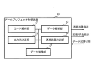
- FIG. 2 is a block diagram showing a configuration of a data prefetch control device in the computer system according to the first embodiment.
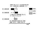
- FIG. 3 is a diagram illustrating processing in a computer system according to the first embodiment.
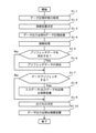
- FIG. 4 is a flowchart showing the operation of the computer system according to the first embodiment.
- FIG. 5 is a block diagram showing a configuration of a data prefetch control device in the computer system according to the second embodiment.
- FIG. 6 is a block diagram showing a configuration of a data prefetch control device in the computer system according to the third embodiment.
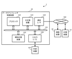
- FIG. 7 is a block diagram showing a hardware configuration of a computer system according to an embodiment of the present invention.
- FIG. 8 is a block diagram showing a configuration of a conventional computer system.
- FIG. 1 is a block diagram showing a configuration of a computer system according to the first embodiment.
- FIG. 2 is a block diagram showing a configuration of a data prefetch control device in the computer system according to the first embodiment.
- FIG. 3 is a diagram illustrating processing in a computer system according to the first embodiment.
- the computer system 1 of the present embodiment includes N first to N (N is an integer of 1 or more) storage devices (10 to 10-N), a data prefetch control device 20, and a data prefetch control device 20. It is provided with M first to M (M is an integer of 1 or more) arithmetic units (30 to 30-M) including an arithmetic unit and a storage unit, and a communication network connecting the storage device 10 and the arithmetic unit 30. ing. As a whole, the computer system 1 is used in the first to M arithmetic units (30 to 30-M) with respect to the data output by the first to N storage devices (10 to 10-N) via the communication network. Performs a predetermined operation or process, and outputs the operation result.
- the difference from the conventional computer system 1 shown in FIG. 8 is that the data prefetch control device 20 is provided.
- the storage device 10 needs to transmit data to the arithmetic unit 30 every time all the data necessary for the processing is processed, whereas the computer system 1 of the present embodiment has the computer system 1 of the present embodiment.
- the data prefetch control device 20 predicts data that may be used for the processing, and the arithmetic unit 30 holds the data in advance. As a result, it is possible to shorten the time until all the data required for the processing are collected in the arithmetic unit 30, and there is an effect that the processing time of the processing can be reduced.
- the data prefetch control device 20 instructs the arithmetic unit 30 to hold data that will be used repeatedly in the process. As a result, the amount of data transmitted / received between the storage device 10 and the arithmetic unit 30 can be reduced, which has the effect of reducing the power consumption and the communication network load.
- the storage device 10 is a data output device having a function of storing data and transmitting the data from the data prefetch control device 20 to the arithmetic unit 30 designated.
- a data generation device having a function of generating data and transmitting the data to the arithmetic unit 30 designated by the data prefetch control device may be used.
- the storage device 10 corresponds to a device specialized for data retention such as a data storage or a data server, or a general-purpose computer generally having a storage function. Further, the data generation device corresponds to a device having a function of generating data by its own device such as a sensor terminal. In the present embodiment, the storage device 10 that outputs the stored data is used as the data output device.
- the data generation device holds the data until the transmission start time specified by the data prefetch control device 20.
- the data may be stored in an external storage device or the like.
- FIG. 2 is a block diagram showing a configuration of a data prefetch control device in the computer system according to the first embodiment.
- the data prefetch control device 20 has a function of managing the data stored in each arithmetic unit 30, the data read from the storage device 10, and the result processed by the arithmetic unit 30 are predetermined by the arithmetic unit 30.
- the function of determining whether or not to store the data within the time, the function of determining whether or not to erase the data stored in each arithmetic unit 30, and the data storage state of each arithmetic unit 30 are taken into consideration.
- the data prefetch control device 20 is any of the first to M in consideration of the data management unit 25 that manages the data stored in each arithmetic unit 30 and the data storage state of each arithmetic unit 30.
- the arithmetic unit determination unit 2423 that determines whether to execute the processing in the arithmetic unit (30 to 30-M), and the storage device (10 to 10-N) of the first to N that stores the result processed by each arithmetic unit 30. ),
- the output destination determination unit 23 that determines whether to store the data, the data amount determination unit 21 that determines the amount of data to be prefetched by each arithmetic unit 30, and the data prefetched by each arithmetic unit 30 are hit.
- the data amount determination unit 21 determines whether or not the data read from the storage device 10 and the result processed by the arithmetic unit 30 are stored in the arithmetic unit 30 within a predetermined time, and each arithmetic unit 30. In order to determine whether or not to erase the stored data, the amount of prefetch data in the arithmetic unit 30 is determined.
- a predetermined ratio of data stored in the storage device 10 is prefetched by the arithmetic unit 30.
- the data analysis unit 22 statistically collects and analyzes whether or not the prefetched data in each arithmetic unit 30 is hit. If the prefetch hit rate is lower than the threshold, the amount of prefetch data is increased, and if the prefetch hit rate is higher than the threshold, the amount of prefetch data is maintained or decreased.
- the data prefetch control device 20 considers the data storage state of each arithmetic unit 30 and determines which arithmetic unit (30 to 30-M) of the first to M to execute the process, the arithmetic unit 30. It is determined whether or not the data in the storage unit of the above can be used in the processing. If it is available, the arithmetic unit 30 is selected.
- FIG. 3 is a diagram illustrating processing in the computer system according to the first embodiment.
- the first arithmetic unit is selected as the arithmetic unit 30 that performs the processing B.
- the data for performing the process A is prefetched, and in the third arithmetic unit, the result of the process A is transmitted from the first arithmetic unit to the third arithmetic unit in order to perform the process C. Will be done.
- the arithmetic unit 30 searches whether the data that can be used in the other arithmetic unit 30 is stored in the storage unit. If data that can be used in any of the first to M arithmetic units (30 to 30-M) is not stored, the arithmetic unit 30 can be sequentially selected from the one with the lowest utilization rate of the storage unit of the arithmetic unit 30. good.
- the data stored in the arithmetic unit 30 may be erased by the input of a signal instructing the arithmetic unit 30 to erase from the outside. Further, when the amount of data stored in the arithmetic unit 30 becomes larger than a predetermined value, the stored data may be sequentially deleted from the one with the lowest utilization rate.
- the arithmetic unit 30 has a function of performing a predetermined arithmetic or processing on the data input from the storage apparatus 10 and outputting the arithmetic result.
- the output of the arithmetic unit 30 is input to the storage device 10 or another arithmetic unit 30 via the communication network.
- the computer system 1 can be applied to a program composed of a plurality of steps that cannot be completed by one arithmetic unit 30.
- the arithmetic unit 30 may be realized by software on a CPU or GPU, or an LSI (Large Scale Integration) circuit formed in an FPGA (Field Programmable Gate Array) or an ASIC (Application Specific Integrated Circuit).
- LSI Large Scale Integration
- FPGA Field Programmable Gate Array
- ASIC Application Specific Integrated Circuit
- the communication network targets any network topology or configuration. For example, there are network topologies such as tree type, star type, torus structure, and PON (Passive Optical Network) used in FTTH (Fiber to the home). Further, as a component, a network device such as a network switch or a router may be included.
- the data may be broadcast-transmitted to a plurality of arithmetic units 30 and the tasks may be processed in parallel.
- any arithmetic unit 30 may be selected, but for example, the one having better calculation performance of the arithmetic unit 30 is selected. Alternatively, the one with a low load on the arithmetic unit 30 at that time may be selected.
- the arithmetic unit 30 does not necessarily have to prefetch all the data necessary for the processing. For example, when only a part of the data is prefetched, only the remaining data necessary for the processing is used. , The data may be transmitted from the storage device 10 to the arithmetic unit 30.
- FIG. 4 is a flowchart showing the operation of the computer system according to the first embodiment.
- the data prefetch control device 20 acquires the data information stored inside each arithmetic unit 30 (step S1-1). Next, the data prefetch control device 20 determines which of the first to M arithmetic units (30 to 30-M) to execute the process in consideration of the data storage state of each arithmetic unit 30 (step). S1-2).
- the storage device 10 outputs data to the arithmetic unit 30 designated by the data prefetch control device (step S1-3).
- the arithmetic unit 30 performs a predetermined arithmetic processing on the data input from the storage device 10 (step S1-4).
- the data prefetch control device 20 determines whether or not to erase the data stored in each arithmetic unit 30 (S1-5). When it is determined that the data is to be erased, an instruction to erase the data is given to the arithmetic unit 30, and the data of each arithmetic unit 30 is erased (step S1-6). When it is determined that the data is not erased, each arithmetic unit 30 continues the storage without erasing the data stored inside.
- the data prefetch control device 20 determines whether or not the data read from the storage device 10 and the result processed by the arithmetic unit 30 are stored in the arithmetic unit 30 within a predetermined time (step S1). -7). If it is determined to be stored, the arithmetic unit 30 stores the input data or the processing result in a predetermined area (step S1-8).
- the data prefetch control device 20 outputs the result processed by each arithmetic unit 30 to which of the first to N storage devices 10 and determines whether to store the result (step S1-9).
- the arithmetic unit 30 outputs the arithmetic result to the storage device 10 of the output destination designated by the data prefetch control apparatus 20 (steps S1-9 and S1-10).
- the arithmetic unit 30 outputs the arithmetic result to the storage device 10 of the output destination designated by the data prefetch control apparatus 20 (steps S1-9 and S1-10).
- the data prefetch control device 20 predicts the data that may be used for the processing, and the arithmetic unit 30 holds the data in advance. As a result, it is possible to shorten the time until all the data required for the processing are collected in the arithmetic unit 30, and it is possible to reduce the processing time of the processing.
- the data prefetch control device 20 instructs the arithmetic unit 30 to hold data that will be used repeatedly in the process. As a result, the amount of data transmitted / received between the storage device 10 and the arithmetic unit 30 can be reduced, so that it is possible to reduce the power consumption and the communication network load.
- the data can be efficiently shared by utilizing the route setting and prefetch data of the communication network.
- FIG. 5 is a block diagram showing a configuration of a data prefetch control device in the computer system according to the second embodiment.
- the difference from the first embodiment is that the data prefetch control device 20 estimates the relationship between the processing content and the data used in the processing by the neural network, and determines whether to prefetch the data based on the estimation result. It is a point to do.
- the data prefetch control device 20 has a function of managing the data stored in each arithmetic unit 30, the data read from the storage device 10, and the result processed by the arithmetic unit 30 for a predetermined time in the arithmetic unit 30.
- the function of determining which arithmetic unit (30 to 30-M) of the first to M to execute the processing in consideration of the data storage state of 30, and the result of processing by each arithmetic unit 30 are the first to the first. It has a function of outputting to which storage device (10 to 10-N) of N and determining which storage device to store.
- the data prefetch control device 20 is any of the first to M in consideration of the data management unit 25 that manages the data stored in each arithmetic unit 30 and the data storage state of each arithmetic unit 30.
- the arithmetic unit determination unit 2423 that determines whether to execute the processing in the arithmetic unit (30 to 30-M), and the storage device (10 to 10-N) of the first to N that stores the result processed by each arithmetic unit 30. ),
- the output destination determination unit 23 that determines whether to store the data, the data learning unit that determines the data to be prefetched by each arithmetic unit 30 in the neural network processing, and the data prefetched by each arithmetic unit 30. It is provided with a data analysis unit 22 that statistically collects and analyzes whether or not a hit has been made.
- the data learning unit estimates the relationship between the processing content and the data used in the processing using a neural network. Based on the estimation result by this neural network, whether or not the data read from the storage device 10 and the result processed by the arithmetic unit 30 are stored in the arithmetic unit 30 within a predetermined time, and in each arithmetic unit 30. Determine whether to erase the stored data.
- the data analysis unit 22 statistically collects and analyzes whether or not the prefetched data in each arithmetic unit 30 is hit.
- the prefetch data learning unit updates / changes to the model of the neural network that has been trained separately offline using a different data set, or uses an approach based on reinforcement learning to obtain the neural network. You can adjust the parameters.
- the neural network There are no restrictions on the neural network that can be used.
- the learning of the neural network is carried out by using the logs and the like when the processing was performed using this system in the past.
- the data prefetch control device 20 predicts the data that may be used for the processing by the neural network processing, and the calculation device 30 holds the data in advance. As a result, it is possible to shorten the time until all the data required for the processing are collected in the arithmetic unit 30, and there is an effect that the processing time of the processing can be reduced.
- the data prefetch control device 20 instructs the arithmetic unit 30 to hold data that will be used repeatedly in the process. As a result, the amount of data transmitted / received between the storage device 10 and the arithmetic unit 30 can be reduced, which has the effect of reducing the power consumption and the communication network load.
- the data can be efficiently shared by utilizing the route setting and prefetch data of the communication network.
- FIG. 6 is a block diagram showing a configuration of a data prefetch control device in the computer system according to the third embodiment.
- the difference from the first and second embodiments is that the data prefetch control device 20 analyzes the program or source code of the arithmetic processing, and the arithmetic unit 30 prefetches the data required for the processing.
- the data prefetch control device 20 has a function of managing the data stored in each arithmetic unit 30, the data read from the storage device 10, and the result processed by the arithmetic unit 30 for a predetermined time in the arithmetic unit 30.
- the data prefetch control device 20 is any of the first to M in consideration of the data management unit 25 that manages the data stored in each arithmetic unit 30 and the data storage state of each arithmetic unit 30.
- the arithmetic unit determination unit 2423 that determines whether to execute the processing in the arithmetic unit (30 to 30-M), and the storage device (10 to 10-N) of the first to N that stores the result processed by each arithmetic unit 30. ),
- the output destination determination unit 23 that determines whether to store the data, the code analysis unit that determines the data to be prefetched by each arithmetic unit 30 based on the result of analyzing the program or the source code, and each arithmetic unit 30. It includes a data analysis unit 22 that statistically collects and analyzes whether or not the prefetched data is hit.
- the code analysis unit determines the data to be prefetched by each arithmetic unit 30 based on the result of analyzing the program for performing arithmetic processing or the source code.
- the code analysis unit analyzes the necessary data from the program or source code from the start to the end of the process, and the data read from the storage device 10 based on the analysis result and the result processed by the arithmetic unit 30. It is determined whether or not the arithmetic unit 30 stores the data within a predetermined time, and whether or not the data stored in each arithmetic unit 30 is erased.
- the data is retained in the arithmetic unit 30, and when the same data is not used repeatedly, the data is not retained. Further, if there is unnecessary data by code analysis among the prefetch data stored in the arithmetic unit 30, the data is cleared.
- the data analysis unit 22 statistically collects and analyzes whether or not the prefetched data in each arithmetic unit 30 is hit.
- the code analysis unit will perform the code analysis in more detail if it is possible to set how much detail the code analysis should be performed.
- code analysis when targeting a process that repeatedly uses the same data, code analysis is limited to the parts that have a loop structure.
- analysis may be performed including whether or not the same data is used among a plurality of functions.
- the data prefetch control device 20 analyzes the program or source code of the processing, predicts the data that may be used in the processing, and preliminarily calculates the arithmetic unit 30. Keep it at. As a result, it is possible to shorten the time until all the data required for the processing are collected in the arithmetic unit 30, and it is possible to reduce the processing time of the processing.
- the data prefetch control device 20 instructs the arithmetic unit 30 to hold data that will be used repeatedly in the process. As a result, the amount of data transmitted / received between the storage device 10 and the arithmetic unit 30 can be reduced, which has the effect of reducing the power consumption and the communication network load.
- the data can be efficiently shared by utilizing the route setting and prefetch data of the communication network.
- the data prefetch control device 20 of the computer system 1 is, for example, a processor 102, a main storage device 103, a communication interface 104, an auxiliary storage device 105, and an input / output I / O 106 connected via a bus 101. It can be realized by a computer equipped with a computer and a program that controls these hardware resources.
- the data prefetch control device 20 is connected to the arithmetic unit 30 and the storage device 10 via the communication network NW.
- the main storage device 103 is realized by, for example, a semiconductor memory such as a SRAM, a DRAM, and a ROM.
- the main storage device 103 realizes the storage unit described with reference to FIG. 1 and the like.
- the main storage device 103 stores in advance a program for the processor 102 to perform various controls and operations.
- the function of the data prefetch control device 20 is realized by the processor 102 and the main storage device 103.
- the communication interface 104 is an interface circuit for communicating with the storage device 10 via the communication network NW.
- the data prefetch control device 20 instructs the arithmetic unit 30 connected via the communication interface 104 to store / erase data, and the arithmetic unit 30 transmits the arithmetic result to the storage device 10 via the communication network NW. ..
- the communication interface 104 for example, an interface and an antenna compatible with wireless data communication standards such as LTE, 3G, wireless LAN, and Bluetooth (registered trademark) are used.
- the communication network NW includes, for example, WAN (Wide Area Network), LAN (Local Area Network), the Internet, a dedicated line, a wireless base station, a provider, and the like.
- the auxiliary storage device 105 is composed of a readable / writable storage medium and a drive device for reading / writing various information such as programs and data to the storage medium.
- a semiconductor memory such as a hard disk or a flash memory can be used as the storage medium in the auxiliary storage device 105.
- the auxiliary storage device 105 has a program storage area for storing a program for the arithmetic unit 30 to perform arithmetic processing. Further, the auxiliary storage device 105 may have, for example, a backup area for backing up the above-mentioned data, programs, and the like.
- the input / output I / O 106 is composed of an I / O terminal that inputs a signal from the external device 107 and outputs a signal to the external device 107.
- the data prefetch control device 20 may be distributed not only by one computer but also by a plurality of computers connected to each other by a communication network NW. Further, the processor 102 may be realized by an LSI (Large Scale Integration) circuit formed in an FPGA (Field Programmable Gate Array) or an ASIC (Application Specific Integrated Circuit).
- LSI Large Scale Integration
- FPGA Field Programmable Gate Array
- ASIC Application Specific Integrated Circuit
- the data prefetch control device 20 can be configured by using a rewritable gate array such as FPGA.
- a computer system 1 capable of supporting various applications can be realized.
Landscapes
- Engineering & Computer Science (AREA)
- Theoretical Computer Science (AREA)
- Physics & Mathematics (AREA)
- General Engineering & Computer Science (AREA)
- General Physics & Mathematics (AREA)
- Memory System Of A Hierarchy Structure (AREA)
- Information Retrieval, Db Structures And Fs Structures Therefor (AREA)
Abstract
本発明のコンピュータシステムは、N(Nは2以上の整数)台のデータ出力装置(10)と、データプリフェッチ制御装置(30)と、M(Mは1以上の整数)台の演算装置(40)とを備え、演算装置(40)は、データ出力装置(10)と演算装置(40)との間を接続する通信ネットワークを介して、N台のデータ出力装置(10)から収集されたデータに対して演算処理を実行し、データプリフェッチ制御装置(30)は、データ出力装置(10)から読み出したデータと、演算装置(40)にて処理した結果を、演算装置(40)において記憶するか、あるいは消去するかを、演算装置(40)に指示するように構成される。通信ネットワークで接続された記憶装置や演算装置間のデータ移動を効率よく行うことができるコンピューティングシステムを提供することができる。
Description
本発明は、通信ネットワークを介して演算装置と複数の記憶装置またはデータ生成装置が接続されたシステムにおいて、全体が協調して動作するコンピュータシステムに関する。
機械学習や人工知能(AI)やIoT(Internet of Things) など多くの分野で技術革新が進み、様々な情報やデータを活用することで、サービスの高度化・付加価値の提供が盛んに行われている。このような処理では、大量の計算をする必要があり、そのための情報処理基盤が必須である。
例えば、非特許文献1では、既存の情報処理基盤をアップデートしようとする試みが展開されてはいるものの、急速に増えていくデータに対して現代のコンピュータが対応しきれていないのも事実であり、今後さらなる進化を遂げていくためには、ムーアの法則を越える「ポストムーア技術」が確立されなければいけないと指摘している。
ポストムーア技術として、例えば、非特許文献2では、フローセントリックコンピューティングという技術が開示されている。フローセントリックコンピューティングでは、データのある場所で処理を行うというこれまでのコンピューティングの考えではなく、計算機能が存在する場所にデータを移動して処理を行うという新たな概念を導入した。
"NTT Technology Report for Smart World 2020," 日本電信電話株式会社,2020年,<URL:https://www.rd.ntt/_assets/pdf/techreport/NTT_TRFSW_2020_EN_W.pdf>
R. Takano and T. Kudoh, "Flow-centric computing leveraged by photonic circuit switching for the post-moore era," Tenth IEEE/ACM International Symposium on Networks-on-Chip (NOCS), Nara, 2016, pp. 1-3,<URL:https://ieeexplore.ieee.org/abstract/document/7579339>
A. J. Smith, "Sequential Program Prefetching in Memory Hierarchies," in Computer, vol. 11, no. 12, pp. 7-21, Dec. 1978,<URL:https://ieeexplore.ieee.org/document/1646791>
上記のようなフローセントリックコンピューティングを実現するためには、データ移動に必要な広帯域な通信ネットワークが必要になるだけでなく、同時に効率よく通信ネットワークを制御しないと、データの移動を効率よく実施できない可能性がある。
一般に、プリフェッチと呼ばれる技術がコンピュータアーキテクチャ分野では広く知られており、データ移動の高速化・高効率化のために用いられる(例えば、非特許文献3)。プリフェッチは、予測アルゴリズムに基づきメモリアクセスを先行させることで、プロセッサが処理を開始する前に必要なメモリアクセス時間を削減・隠蔽することが可能である。しかしながら、上記のような、通信ネットワークを介したフローセントリックコンピューティングにおいて、当該技術を適用している例は開示されていない。
本発明は、上述した課題を解決するためになされたものであり、通信ネットワークで接続された記憶装置や演算装置間のデータ移動を効率よく行うことができるコンピューティングシステムを提供することを目的とする。
上述した課題を解決するために、本発明に係るコンピュータシステムは、N(Nは2以上の整数)台のデータ出力装置と、データプリフェッチ制御装置と、M(Mは1以上の整数)台の演算装置とを備え、前記演算装置は、前記データ出力装置と前記演算装置との間を接続する通信ネットワークを介して、N台の前記データ出力装置から収集されたデータに対して演算処理を実行し、前記データプリフェッチ制御装置は、前記データ出力装置から読み出したデータと、前記演算装置にて処理した結果を、前記演算装置において記憶するか、あるいは消去するかを、前記演算装置に指示するように構成されるように構成される。
本発明によれば、通信ネットワークで接続された記憶装置や演算装置間のデータ移動を効率よく行うことができるコンピューティングシステムを提供することができる。
以下、本発明の好適な実施の形態について、図面を参照して説明する。本発明は、以下の実施の形態に限定されるものではない。
[第1の実施の形態]
図1~3を参照して、本発明の第1の実施の形態にかかるコンピュータシステム1の構成について説明する。図1は、第1の実施の形態にかかるコンピュータシステムの構成を示すブロック図である。図2は、第1の実施の形態にかかるコンピュータシステムにおけるデータプリフェッチ制御装置の構成を示すブロック図である。図3は、第1の実施の形態にかかるコンピュータシステムにおける処理を説明する図である。
図1~3を参照して、本発明の第1の実施の形態にかかるコンピュータシステム1の構成について説明する。図1は、第1の実施の形態にかかるコンピュータシステムの構成を示すブロック図である。図2は、第1の実施の形態にかかるコンピュータシステムにおけるデータプリフェッチ制御装置の構成を示すブロック図である。図3は、第1の実施の形態にかかるコンピュータシステムにおける処理を説明する図である。
[コンピュータシステム]
図1に示すように、本実施の形態のコンピュータシステム1は、N台の第1~N(Nは1以上の整数)記憶装置(10~10-N)と、データプリフェッチ制御装置20と、演算部および記憶部を具備するM台の第1~M(Mは1以上の整数)演算装置(30~30-M)と、記憶装置10と演算装置30間を接続する通信ネットワークとを備えている。コンピュータシステム1は、全体として、前記通信ネットワークを介して、第1~N記憶装置(10~10-N)が出力したデータに対して、第1~M演算装置(30~30-M)において所定の演算または処理を行い、その演算結果を出力する。
図1に示すように、本実施の形態のコンピュータシステム1は、N台の第1~N(Nは1以上の整数)記憶装置(10~10-N)と、データプリフェッチ制御装置20と、演算部および記憶部を具備するM台の第1~M(Mは1以上の整数)演算装置(30~30-M)と、記憶装置10と演算装置30間を接続する通信ネットワークとを備えている。コンピュータシステム1は、全体として、前記通信ネットワークを介して、第1~N記憶装置(10~10-N)が出力したデータに対して、第1~M演算装置(30~30-M)において所定の演算または処理を行い、その演算結果を出力する。
なお、図8に示す従来のコンピュータシステム1との違いは、データプリフェッチ制御装置20を備える点である。従来のコンピュータシステム1では、記憶装置10は、当該処理に必要な全てのデータの処理を行うたびに演算装置30に送信する必要があるのに対して、本実施の形態のコンピュータシステム1は、データプリフェッチ制御装置20にて、当該処理に用いる可能性のあるデータを予測し、予め演算装置30にて保持しておく。これにより、当該処理に必要な全てのデータが演算装置30にて揃うまでの時間を短縮することができ、当該処理の処理時間を削減できる効果がある。
また、データプリフェッチ制御装置20は、当該処理において、繰り返し使うようなデータを演算装置30にて保持するように指示する。これにより、記憶装置10と演算装置30との間のデータ送受信量を削減できるため、低電力化および通信ネットワーク負荷を低減できる効果がある。
[記憶装置]
記憶装置10は、データを記憶し、当該データをデータプリフェッチ制御装置20から指定される演算装置30に送信する機能を有するデータ出力装置である。データ出力装置として、データを生成し、当該データをデータプリフェッチ制御装置が指定した演算装置30に送信する機能を有するデータ生成装置を用いてもよい。
記憶装置10は、データを記憶し、当該データをデータプリフェッチ制御装置20から指定される演算装置30に送信する機能を有するデータ出力装置である。データ出力装置として、データを生成し、当該データをデータプリフェッチ制御装置が指定した演算装置30に送信する機能を有するデータ生成装置を用いてもよい。
記憶装置10としては、データストレージやデータサーバなどのデータ保持に特化した装置や、一般に記憶機能を有する汎用コンピュータなどが該当する。また、データ生成装置としては、センサ端末等の自装置がデータを生成する機能を有している装置が該当する。本実施の形態では、データ出力装置として、記憶したデータを出力する記憶装置10を用いる。
なお、データ生成装置は、データプリフェッチ制御装置20が指定する送信開始時刻までの間、当該データを保持する。当該データを外部の記憶装置等へ格納しておくこともある。
[データプリフェッチ制御装置]
図2は、第1の実施の形態にかかるコンピュータシステムにおけるデータプリフェッチ制御装置の構成を示すブロック図である。データプリフェッチ制御装置20は、各演算装置30が記憶しているデータを管理する機能と、記憶装置10から読み出したデータと、演算装置30にて処理した結果とを、当該演算装置30にて所定の時間内記憶するか否かを判定する機能と、各演算装置30にて記憶しているデータを消去するか否かを判定する機能と、各演算装置30のデータ記憶状態を考慮して第1~Mのいずれの演算装置(30~30-M)で処理を実行するかを決定する機能と、各演算装置30にて処理した結果を第1~Nのいずれの記憶装置(10~10-N)に出力し、記憶するかを決定する機能とを有する。
図2は、第1の実施の形態にかかるコンピュータシステムにおけるデータプリフェッチ制御装置の構成を示すブロック図である。データプリフェッチ制御装置20は、各演算装置30が記憶しているデータを管理する機能と、記憶装置10から読み出したデータと、演算装置30にて処理した結果とを、当該演算装置30にて所定の時間内記憶するか否かを判定する機能と、各演算装置30にて記憶しているデータを消去するか否かを判定する機能と、各演算装置30のデータ記憶状態を考慮して第1~Mのいずれの演算装置(30~30-M)で処理を実行するかを決定する機能と、各演算装置30にて処理した結果を第1~Nのいずれの記憶装置(10~10-N)に出力し、記憶するかを決定する機能とを有する。
具体的には、データプリフェッチ制御装置20は、各演算装置30が記憶しているデータを管理するデータ管理部25と、各演算装置30のデータ記憶状態を考慮して第1~Mのいずれの演算装置(30~30-M)で処理を実行するかを決定する演算装置決定部2423と、各演算装置30にて処理した結果を第1~Nのいずれの記憶装置(10~10-N)に出力し、記憶するかを決定する出力先決定部23と、各演算装置30にてプリフェッチするデータ量を決定するデータ量決定部21と、各演算装置30においてプリフェッチしているデータがヒットしたか否か、すなわち、使用されたか否かを統計的に収集し解析するデータ解析部22とを備える。
データ量決定部21は、記憶装置10から読み出したデータと、演算装置30にて処理した結果と、を当該演算装置30にて所定の時間内記憶するか否か、および各演算装置30にて記憶しているデータを消去するか否か、を判定するために、当該演算装置30におけるプリフェッチデータ量を決定する。
例えば、記憶装置10が記憶するデータのうち所定の割合のデータを当該演算装置30にてプリフェッチする。このとき、データ解析部22は、各演算装置30においてプリフェッチしているデータがヒットしたか否かを統計的に収集し解析する。プリフェッチヒット率が閾値よりも低い場合には、プリフェッチデータ量を増加させて、プリフェッチヒット率が閾値よりも高い場合には、プリフェッチデータ量を維持または減らす。
データプリフェッチ制御装置20は、各演算装置30のデータ記憶状態を考慮して第1~Mのいずれの演算装置(30~30-M)で処理を実行するかを決定する際に、演算装置30の記憶部のデータを当該処理において利用できるか否かを判定する。利用できる場合は当該演算装置30を選択する。
図3は、第1の実施の形態にかかるコンピュータシステムにおける処理を説明する図である。図3の例では、第1演算装置で処理したデータを、処理Bで流用可能なデータであるため処理Bを行う演算装置30として第1演算装置が選択されている。また、第2演算装置では、処理Aを行うためのデータがプリフェッチされ、第3演算装置においては、処理Cを行うために処理Aの結果が、第1演算装置にから第3演算装置に送信される。
一方、利用できない場合は、他の演算装置30において利用できるデータが記憶部に保持されているかを探索する。第1~Mのいずれの演算装置(30~30-M)においても利用できるデータが記憶されていない場合は、演算装置30の記憶部の利用率が少ないものから演算装置30を順次選択すればよい。
なお、上記の例では所定の時間の経過を契機として、演算装置30にて記憶しているデータを消去する例を示したが、消去するか否かの判定はこれに限らない。例えば、演算装置30に対して、外部から消去を指示する信号の入力を契機として、演算装置30にて記憶しているデータを消去するようにしてもよい。また、演算装置30にて記憶しているデータの量が所定の値よりも大きくなった場合に、記憶しているデータの利用率の低いものから順次消去するようにしてもよい。
[演算装置]
演算装置30は、記憶装置10から入力されたデータに対して、所定の演算または処理を行い、その演算結果を出力する機能を有する。演算装置30の出力は、通信ネットワークを介して、記憶装置10または他の演算装置30へ入力される。他の演算装置30へ入力することで、一つの演算装置30で完了しないような複数のステップから構成されるプログラムに対しても、コンピュータシステム1を適用できる。
演算装置30は、記憶装置10から入力されたデータに対して、所定の演算または処理を行い、その演算結果を出力する機能を有する。演算装置30の出力は、通信ネットワークを介して、記憶装置10または他の演算装置30へ入力される。他の演算装置30へ入力することで、一つの演算装置30で完了しないような複数のステップから構成されるプログラムに対しても、コンピュータシステム1を適用できる。
演算装置30は、CPUやGPU上のソフトウェアや、FPGA(Field Programmable Gate Array)やASIC(Application Specific Integrated Circuit)に形成したLSI(Large Scale Integration)回路で実現してもよい。
通信ネットワークは、任意のネットワークトポロジーまたは構成を対象としている。例えば、ツリー型やスター型、トーラス構造、FTTH(Fiber to the home)で用いられるPON(Passive Optical Network)などのネットワークトポロジーがある。また、構成要素として、ネットワークスイッチやルーターなどのネットワーク機器が含んでもよい。
なお、処理対象タスクが複数あり、そのうちの一部のデータを共用できる場合は、当該データを複数の演算装置30に対してブロードキャスト送信し、当該タスクを並列に処理することもある。
なお、複数の演算装置30にて、当該処理に必要なデータが保持されている場合、いずれの演算装置30を選択しても良いが、例えば、より演算装置30の計算性能がよいものを選択したり、また当該時刻における演算装置30の負荷が低いものを選択するようにしてもよい。
なお、演算装置30にて、必ずしも当該処理に必要な全てのデータがプリフェッチされている必要はなく、例えば、一部のデータのみプリフェッチされている場合は、当該処理に必要な残りのデータのみを、記憶装置10から演算装置30へ送信すればよい。
[第1の実施の形態の動作]
図4を参照して、第1の実施の形態にかかるコンピュータシステム1の動作について説明する。図4は、第1の実施の形態にかかるコンピュータシステムの動作を示すフローチャートである。
図4を参照して、第1の実施の形態にかかるコンピュータシステム1の動作について説明する。図4は、第1の実施の形態にかかるコンピュータシステムの動作を示すフローチャートである。
まず、データプリフェッチ制御装置20は、各演算装置30の内部に記憶されているデータの情報を取得する(ステップS1-1)。次に、データプリフェッチ制御装置20は、前記各演算装置30のデータ記憶状態を考慮して第1~Mのいずれの演算装置(30~30-M)で処理を実行するかを決定する(ステップS1-2)。
次に、記憶装置10は、前記データプリフェッチ制御装置が指定した演算装置30にデータを出力する(ステップS1-3)。
次に、演算装置30は、記憶装置10から入力されるデータに対して、所定の演算処理を実施する(ステップS1-4)。
次に、データプリフェッチ制御装置20は、各演算装置30にて記憶しているデータを消去するか否かを判定する(S1-5)。データを消去すると判定した場合は、当該演算装置30に対して、データを消去する指示を出し、各演算装置30のデータを消去する(ステップS1-6)。データを消去しないと判定した場合は、各演算装置30は内部に記憶しているデータを消去することなく記憶を継続する。
次に、データプリフェッチ制御装置20は、記憶装置10から読み出したデータと、演算装置30にて処理した結果とを当該演算装置30にて所定の時間内記憶するか否かを判定する(ステップS1-7)。記憶すると判定した場合、当該演算装置30は、所定の領域に入力データまたは処理結果を記憶する(ステップS1-8)。
次に、データプリフェッチ制御装置20は、各演算装置30にて処理した結果を第1~Nのいずれの記憶装置10に出力し、記憶するかを決定する(ステップS1-9)。
次に、演算装置30は、データプリフェッチ制御装置20が指定した出力先の記憶装置10に対して演算結果を出力する(ステップS1-9、S1-10)。ここで、必ずしも処理の開始前に入力データを読み出した記憶装置10に対して、演算結果を出力しなくともよい。
[第1の実施の形態の効果]
このように、本実施の形態のコンピュータシステム1は、データプリフェッチ制御装置20にて、当該処理に用いる可能性のあるデータを予測し、予め演算装置30にて保持しておく。これにより、当該処理に必要な全てのデータが演算装置30にて揃うまでの時間を短縮することができ、当該処理の処理時間を削減できる。
このように、本実施の形態のコンピュータシステム1は、データプリフェッチ制御装置20にて、当該処理に用いる可能性のあるデータを予測し、予め演算装置30にて保持しておく。これにより、当該処理に必要な全てのデータが演算装置30にて揃うまでの時間を短縮することができ、当該処理の処理時間を削減できる。
また、データプリフェッチ制御装置20は、当該処理において、繰り返し使うようなデータを演算装置30にて保持するように指示する。これにより、記憶装置10と演算装置30との間のデータ送受信量を削減できるため、低電力化および通信ネットワーク負荷の低減を実現できる。
また、ローカライズされているデータを一旦いずれか一つの演算装置30に保持しておけば、そのデータを通信ネットワークの経路設定やプリフェッチデータを活用することで効率よく共有することができる。
[第2の実施の形態]
図5を参照して、本発明の第2の実施の形態にかかるコンピュータシステム1の構成について説明する。図5は、第2の実施の形態にかかるコンピュータシステムにおけるデータプリフェッチ制御装置の構成を示すブロック図である。
図5を参照して、本発明の第2の実施の形態にかかるコンピュータシステム1の構成について説明する。図5は、第2の実施の形態にかかるコンピュータシステムにおけるデータプリフェッチ制御装置の構成を示すブロック図である。
第1の実施の形態との違いは、データプリフェッチ制御装置20において、処理内容とその処理において用いたデータとの関係をニューラルネットワークにより推定し、その推定結果に基づいてデータをプリフェッチするかを判断する点である。
データプリフェッチ制御装置20は、各演算装置30が記憶しているデータを管理する機能と、記憶装置10から読み出したデータと、演算装置30にて処理した結果とを演算装置30にて所定の時間内記憶するか否かを、ニューラルネットワークを用いて判定する機能と、各演算装置30にて記憶しているデータを消去するか否かを、ニューラルネットワークを用いて判定する機能と、各演算装置30のデータ記憶状態を考慮して第1~Mのいずれの演算装置(30~30-M)で処理を実行するかを決定する機能と、各演算装置30にて処理した結果を第1~Nのいずれの記憶装置(10~10-N)に出力し、記憶するかを決定する機能とを有する。
具体的には、データプリフェッチ制御装置20は、各演算装置30が記憶しているデータを管理するデータ管理部25と、各演算装置30のデータ記憶状態を考慮して第1~Mのいずれの演算装置(30~30-M)で処理を実行するかを決定する演算装置決定部2423と、各演算装置30にて処理した結果を第1~Nのいずれの記憶装置(10~10-N)に出力し、記憶するかを決定する出力先決定部23と、ニューラルネットワーク処理にて各演算装置30にてプリフェッチするデータを決定するデータ学習部と、各演算装置30においてプリフェッチしているデータがヒットしたか否かを統計的に収集し解析するデータ解析部22とを備える。
データ学習部は、処理内容とその処理において用いたデータとの関係をニューラルネットワークにより推定する。このニューラルネットワークによる推定結果に基づき、記憶装置10から読み出したデータと、演算装置30にて処理した結果とを演算装置30にて所定の時間内記憶するか否か、および各演算装置30にて記憶しているデータを消去するか否かを判定する。
また、データ解析部22は、各演算装置30においてプリフェッチしているデータがヒットしたか否かを統計的に収集し解析する。プリフェッチヒット率が閾値よりも低い場合、プリフェッチデータ学習部は、別途オフラインで異なるデータセットを用いて学習を行ったニューラルネットワークのモデルに更新・変更したり、強化学習に基づくアプローチにより、ニューラルネットワークのパラメータを調整したりすることができる。
なお、用いるニューラルネットに制限はない。また、ニューラルネットワークの学習は、過去に本システムを用いて処理した際のログ等を利用して実施する。
[第2の実施の形態の効果]
このように、本実施の形態のコンピュータシステム1は、データプリフェッチ制御装置20にて、当該処理に用いる可能性のあるデータをニューラルネットワーク処理によって予測し、予め演算装置30にて保持しておく。これにより、当該処理に必要な全てのデータが演算装置30にて揃うまでの時間を短縮することができ、当該処理の処理時間を削減できる効果がある。
このように、本実施の形態のコンピュータシステム1は、データプリフェッチ制御装置20にて、当該処理に用いる可能性のあるデータをニューラルネットワーク処理によって予測し、予め演算装置30にて保持しておく。これにより、当該処理に必要な全てのデータが演算装置30にて揃うまでの時間を短縮することができ、当該処理の処理時間を削減できる効果がある。
また、データプリフェッチ制御装置20は、当該処理において、繰り返し使うようなデータを演算装置30にて保持するように指示する。これにより、記憶装置10と演算装置30との間のデータ送受信量を削減できるため、低電力化および通信ネットワーク負荷を低減できる効果がある。
また、ローカライズされているデータを一旦いずれか一つの演算装置30に保持しておけば、そのデータを通信ネットワークの経路設定やプリフェッチデータを活用することで効率よく共有することができる。
[第3の実施の形態]
図6を参照して、本発明の第3の実施の形態にかかるコンピュータシステム1の構成について説明する。図6は、第3の実施の形態にかかるコンピュータシステムにおけるデータプリフェッチ制御装置の構成を示すブロック図である。
図6を参照して、本発明の第3の実施の形態にかかるコンピュータシステム1の構成について説明する。図6は、第3の実施の形態にかかるコンピュータシステムにおけるデータプリフェッチ制御装置の構成を示すブロック図である。
第1および第2の実施の形態との違いは、データプリフェッチ制御装置20において、演算処理のプログラムまたはソースコードを解析し、当該処理に必要なデータを演算装置30にてプリフェッチする点である。
データプリフェッチ制御装置20は、各演算装置30が記憶しているデータを管理する機能と、記憶装置10から読み出したデータと、演算装置30にて処理した結果とを演算装置30にて所定の時間内記憶するか否かを、プログラムまたはソースコードを解析した結果に基づき判定する機能と、各演算装置30にて記憶しているデータを消去するか否かを、プログラムまたはソースコードを解析した結果に基づき判定する機能と、各演算装置30のデータ記憶状態を考慮して第1~Mのいずれの演算装置(30~30-M)で処理を実行するかを決定する機能と、各演算装置30にて処理した結果を第1~Nのいずれの記憶装置(10~10-N)に出力し、記憶するかを決定する機能と、を有する。
具体的には、データプリフェッチ制御装置20は、各演算装置30が記憶しているデータを管理するデータ管理部25と、各演算装置30のデータ記憶状態を考慮して第1~Mのいずれの演算装置(30~30-M)で処理を実行するかを決定する演算装置決定部2423と、各演算装置30にて処理した結果を第1~Nのいずれの記憶装置(10~10-N)に出力し、記憶するかを決定する出力先決定部23と、プログラムまたはソースコードを解析した結果に基づき各演算装置30にてプリフェッチするデータを決定するコード解析部と、各演算装置30においてプリフェッチしているデータがヒットしたか否かを統計的に収集し解析するデータ解析部22とを備える。
コード解析部は、演算処理を行うプログラムまたはソースコードを解析した結果に基づき各演算装置30にてプリフェッチするデータを決定する。コード解析部は、当該処理の開始から終了までの間に必要なデータをプログラムまたはソースコードから解析し、解析結果に基いて記憶装置10から読み出したデータと、演算装置30にて処理した結果とを演算装置30にて所定の時間内記憶するか否か、および各演算装置30にて記憶しているデータを消去するか否かを判定する。
具体的には、コード解析の結果、演算処理が同一データを繰り返し使う場合は、当該データを演算装置30に保持しておき、同一データを繰り返し使わない場合は、当該データを保持しない。また、演算装置30に記憶されているプリフェッチデータのうち、コード解析により不要なデータがある場合は、当該データをクリアする。
このとき、データ解析部22は、各演算装置30においてプリフェッチしているデータがヒットしたか否かを統計的に収集し解析する。プリフェッチヒット率が閾値よりも低い場合、コード解析部は、コード解析をどの程度詳細に実施するかを設定できる場合、より詳細にコード解析を行うこととする。
上記コード解析の詳細さ(解析のレベル)については、例えば、同一データを繰り返し使う処理をターゲットとする場合、ループ構造になっている個所に限定したコード解析を行う。より詳細にコード解析を行う場合には、上記に加え、複数の関数の間で同一データを使うか否かを含めて解析すればよい。
[第3の実施の形態の効果]
このように、本実施の形態のコンピュータシステム1は、データプリフェッチ制御装置20にて、当該処理のプログラムまたはソースコードを解析し、当該処理に用いる可能性のあるデータを予測し、予め演算装置30にて保持しておく。これにより、当該処理に必要な全てのデータが演算装置30にて揃うまでの時間を短縮することができ、当該処理の処理時間を削減することができる。
このように、本実施の形態のコンピュータシステム1は、データプリフェッチ制御装置20にて、当該処理のプログラムまたはソースコードを解析し、当該処理に用いる可能性のあるデータを予測し、予め演算装置30にて保持しておく。これにより、当該処理に必要な全てのデータが演算装置30にて揃うまでの時間を短縮することができ、当該処理の処理時間を削減することができる。
また、データプリフェッチ制御装置20は、当該処理において、繰り返し使うようなデータを演算装置30にて保持するように指示する。これにより、記憶装置10と演算装置30との間のデータ送受信量を削減できるため、低電力化および通信ネットワーク負荷を低減できる効果がある。
また、ローカライズされているデータを一旦いずれか一つの演算装置30に保持しておけば、そのデータを通信ネットワークの経路設定やプリフェッチデータを活用することで効率よく共有することができる。
[コンピュータシステムのハードウェア構成]
次に、上述した構成を有するコンピュータシステム1のハードウェア構成の一例について図7を参照して説明する。
次に、上述した構成を有するコンピュータシステム1のハードウェア構成の一例について図7を参照して説明する。
図7に示すように、コンピュータシステム1のデータプリフェッチ制御装置20は、例えば、バス101を介して接続されるプロセッサ102、主記憶装置103、通信インターフェース104、補助記憶装置105、入出力I/O106を備えるコンピュータと、これらのハードウェア資源を制御するプログラムによって実現することができる。データプリフェッチ制御装置20は、通信ネットワークNWを介して演算装置30、記憶装置10と接続されている。
主記憶装置103は、例えば、SRAM、DRAM、およびROMなどの半導体メモリによって実現される。主記憶装置103は、図1等で説明した記憶部を実現する。
主記憶装置103には、プロセッサ102が各種制御や演算を行うためのプログラムが予め格納されている。プロセッサ102と主記憶装置103とによって、データプリフェッチ制御装置20の機能が実現される。
通信インターフェース104は、通信ネットワークNWを介して記憶装置10との通信を行うためのインターフェース回路である。データプリフェッチ制御装置20は、通信インターフェース104を介して接続された演算装置30にデータの記憶/消去を指示し、演算装置30は、通信ネットワークNWを介して、記憶装置10に演算結果を送信する。
通信インターフェース104としては、例えば、LTE、3G、無線LAN、Bluetooth(登録商標)などの無線データ通信規格に対応したインターフェースおよびアンテナが用いられる。通信ネットワークNWは、例えば、WAN(Wide Area Network)やLAN(Local Area Network)、インターネット、専用回線、無線基地局、プロバイダなどを含む。
補助記憶装置105は、読み書き可能な記憶媒体と、その記憶媒体に対してプログラムやデータなどの各種情報を読み書きするための駆動装置とで構成されている。補助記憶装置105には、記憶媒体としてハードディスクやフラッシュメモリなどの半導体メモリを使用することができる。
補助記憶装置105は、演算装置30が演算処理を行うためのプログラムを格納するプログラム格納領域を有する。さらには、補助記憶装置105は、例えば、上述したデータやプログラムやなどをバックアップするためのバックアップ領域などを有していてもよい。
入出力I/O106は、外部装置107からの信号を入力したり、外部装置107へ信号を出力したりするI/O端子により構成される。
なお、データプリフェッチ制御装置20は、1つのコンピュータによって実現される場合だけでなく、互いに通信ネットワークNWで接続された複数のコンピュータによって分散されていてもよい。また、プロセッサ102は、FPGA(Field Programmable Gate Array)やASIC(Application Specific Integrated Circuit)に形成したLSI(Large Scale Integration)回路で実現してもよい。
特に、データプリフェッチ制御装置20をFPGAなどの書き換え可能なゲートアレイを用いて構成することができる。この場合、様々なアプリケーションに対応することが可能なコンピュータシステム1を実現できる。
[実施の形態の拡張]
以上、実施形態を参照して本発明を説明したが、本発明は上記実施形態に限定されるものではない。本発明の構成や詳細には、本発明のスコープ内で当業者が理解しうる様々な変更をすることができる。また、各実施形態については、矛盾しない範囲で任意に組み合わせて実施することができる。
以上、実施形態を参照して本発明を説明したが、本発明は上記実施形態に限定されるものではない。本発明の構成や詳細には、本発明のスコープ内で当業者が理解しうる様々な変更をすることができる。また、各実施形態については、矛盾しない範囲で任意に組み合わせて実施することができる。
1…コンピュータシステム、10、10-N…記憶装置、20…データプリフェッチ制御装置、30、30-M…演算装置、101…バス、102…プロセッサ、103…主記憶装置、104…通信インターフェース、105…補助記憶装置、106…入出力I/O、107…外部装置。
Claims (8)
- N(Nは2以上の整数)台のデータ出力装置と、データプリフェッチ制御装置と、M(Mは1以上の整数)台の演算装置とを備え、
前記演算装置は、前記データ出力装置と前記演算装置との間を接続する通信ネットワークを介して、N台の前記データ出力装置から収集されたデータに対して演算処理を実行し、
前記データプリフェッチ制御装置は、
前記データ出力装置から読み出したデータと、前記演算装置にて処理した結果を、前記演算装置において記憶するか、あるいは消去するかを、前記演算装置に指示するように構成される
コンピュータシステム。 - 請求項1記載のコンピュータシステムであって、
前記データプリフェッチ制御装置は、
前記演算装置においてプリフェッチするデータ量を決定するデータ量決定部を備え、
前記データ量決定部において決定されたプリフェッチするデータ量に基づいて、前記データ出力装置から読み出したデータと、前記演算装置にて処理した結果を、当該演算装置において記憶するか否かを判定するように構成される
コンピュータシステム。 - 請求項2記載のコンピュータシステムであって、
前記データプリフェッチ制御装置は、
前記演算装置においてプリフェッチしたデータがヒットしたか否かを示すデータを解析するデータ解析部を備え、
前記データ量決定部は、
前記データ解析部におけるプリフェッチしたデータのヒット率に基づいて、プリフェッチするデータ量を決定するように構成される
コンピュータシステム。 - 請求項1記載のコンピュータシステムであって、
前記データプリフェッチ制御装置は、
前記演算装置における演算処理と演算処理に用いたデータとの関係をニューラルネットワークにより推定するデータ学習部を備え、
前記データ学習部において推定された演算処理と演算処理に用いたデータとの関係に基づいて、前記データ出力装置から読み出したデータと、前記演算装置にて処理した結果を、当該演算装置において記憶するか否かを判定するように構成される
コンピュータシステム。 - 請求項4記載のコンピュータシステムであって、
前記データプリフェッチ制御装置は、
前記演算装置においてプリフェッチしたデータがヒットしたか否かを示すデータを解析するデータ解析部を備え、
前記データ学習部は、
前記データ解析部におけるプリフェッチしたデータのヒット率に基づいて、前記ニューラルネットワークのモデルを変更し、あるいは、前記ニューラルネットワークのパラメータを変更するように構成される
コンピュータシステム。 - 請求項1記載のコンピュータシステムであって、
前記データプリフェッチ制御装置は、
前記演算装置における演算処理に必要なデータを解析するコード解析部を備え、
前記コード解析部における解析結果に基づいて、前記データ出力装置から読み出したデータと、前記演算装置にて処理した結果を、当該演算装置において記憶するか否かを判定するように構成される
コンピュータシステム。 - 請求項6記載のコンピュータシステムであって、
前記データプリフェッチ制御装置は、
前記演算装置においてプリフェッチしたデータがヒットしたか否かを示すデータを解析するデータ解析部を備え、
前記コード解析部は、
前記データ解析部におけるプリフェッチしたデータのヒット率に基づいて、前記コード解析部におけるコード解析のレベルを変更するように構成される
コンピュータシステム。 - 請求項1~7の何れか1項にコンピュータシステムであって、
前記データプリフェッチ制御装置は、
前記各演算装置のデータ記憶状態に基づいて、M台のいずれの前記演算装置で処理を実行するかを決定するコンピュータシステム。
Priority Applications (2)
| Application Number | Priority Date | Filing Date | Title |
|---|---|---|---|
| PCT/JP2020/030022 WO2022029928A1 (ja) | 2020-08-05 | 2020-08-05 | コンピュータシステム |
| JP2022541410A JP7452663B2 (ja) | 2020-08-05 | 2020-08-05 | コンピュータシステム |
Applications Claiming Priority (1)
| Application Number | Priority Date | Filing Date | Title |
|---|---|---|---|
| PCT/JP2020/030022 WO2022029928A1 (ja) | 2020-08-05 | 2020-08-05 | コンピュータシステム |
Publications (1)
| Publication Number | Publication Date |
|---|---|
| WO2022029928A1 true WO2022029928A1 (ja) | 2022-02-10 |
Family
ID=80117777
Family Applications (1)
| Application Number | Title | Priority Date | Filing Date |
|---|---|---|---|
| PCT/JP2020/030022 Ceased WO2022029928A1 (ja) | 2020-08-05 | 2020-08-05 | コンピュータシステム |
Country Status (2)
| Country | Link |
|---|---|
| JP (1) | JP7452663B2 (ja) |
| WO (1) | WO2022029928A1 (ja) |
Citations (3)
| Publication number | Priority date | Publication date | Assignee | Title |
|---|---|---|---|---|
| JPH06149761A (ja) * | 1992-11-13 | 1994-05-31 | Toshiba Corp | 複合型システム演算装置および方法 |
| JP2004110528A (ja) * | 2002-09-19 | 2004-04-08 | Yaskawa Electric Corp | 信号処理回路 |
| JP2009116813A (ja) * | 2007-11-09 | 2009-05-28 | Japan Aerospace Exploration Agency | 大規模計算用カスタムメイド計算機 |
-
2020
- 2020-08-05 WO PCT/JP2020/030022 patent/WO2022029928A1/ja not_active Ceased
- 2020-08-05 JP JP2022541410A patent/JP7452663B2/ja active Active
Patent Citations (3)
| Publication number | Priority date | Publication date | Assignee | Title |
|---|---|---|---|---|
| JPH06149761A (ja) * | 1992-11-13 | 1994-05-31 | Toshiba Corp | 複合型システム演算装置および方法 |
| JP2004110528A (ja) * | 2002-09-19 | 2004-04-08 | Yaskawa Electric Corp | 信号処理回路 |
| JP2009116813A (ja) * | 2007-11-09 | 2009-05-28 | Japan Aerospace Exploration Agency | 大規模計算用カスタムメイド計算機 |
Also Published As
| Publication number | Publication date |
|---|---|
| JP7452663B2 (ja) | 2024-03-19 |
| JPWO2022029928A1 (ja) | 2022-02-10 |
Similar Documents
| Publication | Publication Date | Title |
|---|---|---|
| US12159194B2 (en) | Software-defined quantum computer | |
| CN111491332A (zh) | 动态服务迁移方法及装置 | |
| US10248324B2 (en) | Oblivious parallel random access machine system and methods | |
| CN113711246B (zh) | 多控制量子状态反转栅极 | |
| US9535949B2 (en) | Dynamic rules to optimize common information model queries | |
| US8914815B2 (en) | Automated framework for tracking and maintaining kernel symbol list types | |
| JP7322345B2 (ja) | シナリオプロファイルベースのパーティショニングおよびアプリケーションコードの管理 | |
| JP7452663B2 (ja) | コンピュータシステム | |
| JP6857196B2 (ja) | 1つまたは複数の通信チャネルにより相互接続された複数の異なるメモリ・ロケーションを有するコンピューティング・システムのアプリケーションを最適化する方法、コンピュータ可読プログラムを含む非一時的コンピュータ可読記憶媒体、およびシステム | |
| CN120354877A (zh) | 一种空管系统网络攻击路径优化方法及系统 | |
| CN111930420A (zh) | 无侵入式通用代码级灰度路由系统及方法 | |
| CN116954926A (zh) | 服务器资源分配方法及装置 | |
| US11392493B2 (en) | System and method for optimizing non-volatile random access memory usage | |
| WO2023173912A1 (zh) | 一种处理单元pe阵列的配置方法和相关设备 | |
| KR100714970B1 (ko) | 컴퓨터 | |
| US20210342070A1 (en) | Method, electronic device, and computer storage medium for information processing | |
| CN116432691A (zh) | 基于机器学习框架的模型训练方法及相关设备 | |
| US12411713B2 (en) | Method for optimizing resource allocation based on prediction with reinforcement learning | |
| CN118233382B (zh) | 拥塞控制方法及拥塞控制模型训练方法、交换机及介质 | |
| CN119892647B (zh) | 网络通信中关键承载点的评估方法、装置、设备及介质 | |
| KR102883102B1 (ko) | 불확실성 값을 이용하여 신경망 모델 내의 학습 데이터를 처리하기 위한 전자 장치 및 그 동작 방법 | |
| CN116028402B (zh) | 基于risc-v的控制方法、系统、芯片及存储介质 | |
| CN117094408B (zh) | 基于量子比特的自适应混合算子数据处理方法及装置 | |
| CN111030856B (zh) | 一种基于云的数据接入方法、电子设备及计算机可读介质 | |
| CN120851234A (zh) | 量子比特映射方法、装置、设备、介质及计算机程序产品 |
Legal Events
| Date | Code | Title | Description |
|---|---|---|---|
| 121 | Ep: the epo has been informed by wipo that ep was designated in this application |
Ref document number: 20947937 Country of ref document: EP Kind code of ref document: A1 |
|
| ENP | Entry into the national phase |
Ref document number: 2022541410 Country of ref document: JP Kind code of ref document: A |
|
| NENP | Non-entry into the national phase |
Ref country code: DE |
|
| 122 | Ep: pct application non-entry in european phase |
Ref document number: 20947937 Country of ref document: EP Kind code of ref document: A1 |