WO2022029822A1 - Dimming agent and light-emitting device containing dimming agent - Google Patents
Dimming agent and light-emitting device containing dimming agent Download PDFInfo
- Publication number
- WO2022029822A1 WO2022029822A1 PCT/JP2020/029632 JP2020029632W WO2022029822A1 WO 2022029822 A1 WO2022029822 A1 WO 2022029822A1 JP 2020029632 W JP2020029632 W JP 2020029632W WO 2022029822 A1 WO2022029822 A1 WO 2022029822A1
- Authority
- WO
- WIPO (PCT)
- Prior art keywords
- light emitting
- dimming
- agent
- light
- dimming agent
- Prior art date
Links
Images


Classifications
-
- H—ELECTRICITY
- H01—ELECTRIC ELEMENTS
- H01L—SEMICONDUCTOR DEVICES NOT COVERED BY CLASS H10
- H01L33/00—Semiconductor devices with at least one potential-jump barrier or surface barrier specially adapted for light emission; Processes or apparatus specially adapted for the manufacture or treatment thereof or of parts thereof; Details thereof
- H01L33/48—Semiconductor devices with at least one potential-jump barrier or surface barrier specially adapted for light emission; Processes or apparatus specially adapted for the manufacture or treatment thereof or of parts thereof; Details thereof characterised by the semiconductor body packages
- H01L33/52—Encapsulations
- H01L33/56—Materials, e.g. epoxy or silicone resin
-
- H—ELECTRICITY
- H01—ELECTRIC ELEMENTS
- H01L—SEMICONDUCTOR DEVICES NOT COVERED BY CLASS H10
- H01L33/00—Semiconductor devices with at least one potential-jump barrier or surface barrier specially adapted for light emission; Processes or apparatus specially adapted for the manufacture or treatment thereof or of parts thereof; Details thereof
- H01L33/48—Semiconductor devices with at least one potential-jump barrier or surface barrier specially adapted for light emission; Processes or apparatus specially adapted for the manufacture or treatment thereof or of parts thereof; Details thereof characterised by the semiconductor body packages
- H01L33/50—Wavelength conversion elements
- H01L33/501—Wavelength conversion elements characterised by the materials, e.g. binder
- H01L33/502—Wavelength conversion materials
- H01L33/504—Elements with two or more wavelength conversion materials
-
- C—CHEMISTRY; METALLURGY
- C09—DYES; PAINTS; POLISHES; NATURAL RESINS; ADHESIVES; COMPOSITIONS NOT OTHERWISE PROVIDED FOR; APPLICATIONS OF MATERIALS NOT OTHERWISE PROVIDED FOR
- C09K—MATERIALS FOR MISCELLANEOUS APPLICATIONS, NOT PROVIDED FOR ELSEWHERE
- C09K3/00—Materials not provided for elsewhere
-
- G—PHYSICS
- G02—OPTICS
- G02B—OPTICAL ELEMENTS, SYSTEMS OR APPARATUS
- G02B5/00—Optical elements other than lenses
- G02B5/20—Filters
- G02B5/22—Absorbing filters
-
- H—ELECTRICITY
- H01—ELECTRIC ELEMENTS
- H01L—SEMICONDUCTOR DEVICES NOT COVERED BY CLASS H10
- H01L2933/00—Details relating to devices covered by the group H01L33/00 but not provided for in its subgroups
- H01L2933/0091—Scattering means in or on the semiconductor body or semiconductor body package
-
- H—ELECTRICITY
- H01—ELECTRIC ELEMENTS
- H01L—SEMICONDUCTOR DEVICES NOT COVERED BY CLASS H10
- H01L33/00—Semiconductor devices with at least one potential-jump barrier or surface barrier specially adapted for light emission; Processes or apparatus specially adapted for the manufacture or treatment thereof or of parts thereof; Details thereof
- H01L33/48—Semiconductor devices with at least one potential-jump barrier or surface barrier specially adapted for light emission; Processes or apparatus specially adapted for the manufacture or treatment thereof or of parts thereof; Details thereof characterised by the semiconductor body packages
- H01L33/50—Wavelength conversion elements
Definitions
- the present invention relates to a dimming agent and a light emitting device containing a dimming agent.
- LEDs used in a dark environment such as in-vehicle applications are required to be not too dazzling so as not to obstruct the driver's vision.
- Patent Document 1 describes an invention relating to a dimming circuit for switching the emission brightness of an in-vehicle LED.
- the injection current into the LED can be changed by using a dimming circuit or the like as described in Patent Document 1. It is possible to adjust the brightness.
- the injection current to the LED is set to a low current, there is a problem that the emission wavelength of the blue LED fluctuates greatly.
- the emission wavelength of the blue LED changes, the chromaticity of the white LED varies.
- the present invention has been made to solve the above problems, and provides a dimming agent capable of suppressing brightness without lowering the current value of the current injected into the LED, and a light emitting device using the same.
- the purpose is to do.
- the present invention has been made to achieve the above object, and is characterized by containing at least one of terbium, praseodymium, manganese, and titanium, and has a diffuse reflection intensity of 80% or less at a wavelength of 400 nm to 750 nm. Provide a dimming agent.
- a dimming agent for a light emitting device whose brightness is suppressed to a low level without lowering the current value of the current injected into the LED. Therefore, the change in the emission wavelength of the LED, that is, the change in the chromaticity is suppressed, and the light emitting device is suitable for use in a dark environment such as an automobile.
- a dimming agent having a diffuse reflection intensity of 80% or less at a wavelength of 400 nm to 750 nm which contains an alkaline earth metal as a constituent element and contains at least one of terbium, praseodymium, manganese, and titanium. Can be done.
- the base material of the dimming agent in the same way as the phosphor containing alkaline earth metals.
- terbium, praseodymium, manganese, and titanium can be added like a fluorescent agent.
- a dimming agent like a phosphor it is possible to control the specific gravity and the particle size, and it can be adjusted as a factor for uniform dispersion with the phosphor.
- the emission peak wavelength of the light emitting element is in the range of 380 to 490 nm, and the light emitting device containing the dimming agent can be used.
- the emission peak wavelength of the light emitting element is in the range of 380 to 490 nm, and the light emitting device including the dimming agent and the phosphor can be used.
- the brightness is suppressed to a low level without lowering the current value of the current injected into the LED. Therefore, the change in the emission wavelength of the LED, that is, the change in the chromaticity is suppressed, and the light emitting device is suitable for use in a dark environment such as an automobile.
- the dimming agent of the present invention becomes a light emitting device whose brightness is suppressed without lowering the current value of the current injected into the LED. Further, by using a phosphor, it is possible to provide a light emitting device having various brightness not only in blue but also in green, yellow, red and white.
- An example of a light emitting device is shown.
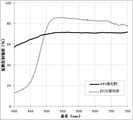
- the diffuse reflection spectra of the AlN dimming agent and the BOS phosphor are shown.
- the diffuse reflection spectrum of the powder with a dark body color is shown.
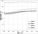
- the diffuse reflection spectra of Comparative Example 1 and Examples 1, 2 and 3 are shown.
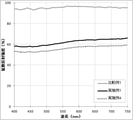
- the diffuse reflection spectra of Comparative Example 1 and Examples 1 and 4 are shown.
- the emission spectra of Comparative Example 2 and Example 5 are shown.
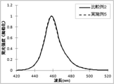
- the standardized emission spectra of Comparative Example 2 and Example 5 are shown.
- the emission spectra of Comparative Example 3 and Example 6 are shown.
- the standardized emission spectra of Comparative Example 3 and Example 6 are shown.
- An explanatory diagram is shown in which the luminous flux of the LED changes according to the injection current to the LED.
- the fluctuation of the emission wavelength of the blue LED when the injection current to the LED is set to a constant current is shown.
- the present inventors have reduced the diffuse reflection intensity at a wavelength of 400 nm to 750 nm by 80% or less, which is characterized by containing at least one of terbium, placeodim, manganese, and titanium.
- a light emitting device having a low brightness without lowering the current value of the injection current to the LED by using a light agent, and completed the present invention.
- the light emitting element, the dimming agent according to claim 1 and 2 which absorbs a part of the light from the light emitting element, and the light emitting element by absorbing a part of the light from the light emitting element.
- light emitting devices used in dark environments such as white LEDs for automobiles
- white LEDs for automobiles are required to have brightness that can be recognized in sunlight during the day and brightness that is not too bright at night.
- an LED having a luminous intensity of 300 mcd is the mainstream.
- those placed near the driver are required in the market to have a luminous intensity of 120 mcd or less, particularly 100 to 10 mcd, from the viewpoint of safety at night.
- the light emitting wavelength (peak wavelength) of the blue LED varies as described above, and the chromaticity of the white LED becomes different. It will change.
- the blue LED with low luminous efficiency can be produced with stable quality.
- a dimming agent having a diffuse reflection intensity of 80% or less from 400 nm to 750 nm and a part of the light from the light emitting element are absorbed and converted into light having an emission peak wavelength different from the peak wavelength of the emission wavelength of the light emitting element.
- a white LED having a light intensity of 30 mcd or less could be obtained.
- the dimming effect of terbium and praseodymium is weak when a trivalent rare earth element is contained as a constituent element of the dimming agent. Therefore, a parent crystal containing a divalent alkaline earth metal is preferable.
- FIG. 1 shows an example of a light emitting device 100 according to the present invention.
- the light emitting device 100 according to the present invention includes a light emitting element 10 arranged on the substrate 40 and a dimming agent 2 that absorbs a part of the light from the light emitting element 10, and the dimming agent 2 includes the light emitting element 10. It is dispersed in a resin layer 20 that functions as a resin encapsulant to be coated, and is housed in a package 30. Additives such as Aerosil can be appropriately added to the resin layer 20 in order to enhance the dispersibility of the dimming agent 2 and the like.
- the dimming agent 2 contains at least one of terbium, praseodymium, manganese, and titanium, and has a diffuse reflection intensity of 80% or less at a wavelength of 400 nm to 750 nm. By using such a dimming agent 2, a blue light emitting device having suppressed brightness can be obtained without lowering the current value of the current injected into the LED.
- the resin layer 20 can contain the phosphor 1 (1a, 1b).
- the present inventors can produce a dark light emitting device that exhibits various emission colors such as green, yellow, and red as well as white.
- a blue LED having an output of 60 mcd and a dominant wavelength of 458 nm was used as the light emitting element 10 when a current of 5 mA was applied.
- FIG. 2 shows the diffuse reflection spectrum of the dimming agent currently used.
- the diffuse reflection spectrum of a commercially available product (Ba, Sr) 2 SiO 4 : Eu fluorescent substance (hereinafter abbreviated as BOS fluorescent substance) having an emission peak wavelength of 530 nm is also shown in FIG. It can be seen that the BOS phosphor selectively absorbs light of 500 nm or less, whereas the AlN dimming agent uniformly absorbs light of 400 nm to 750 nm.
- the light absorption of the AlN dimming agent is not so strong.
- the amount of AlN dimming agent used increases.
- the powder concentration in the resin increases, the resin viscosity increases, making uniform coating difficult.
- FIG. 3 shows the diffuse reflection spectrum of the powder having a dark body color.
- Terbium oxide (Tb 4 O 7 ), praseodymium oxide (Pr 4 O 11 ), and manganese oxide (MnO 2 ) are materials often used in the production of phosphors, and have strong light in a wide range of wavelengths from 400 nm to 750 nm. It turns out that there is absorption.
- Titanium is a variety of compounds used as raw materials for phosphors, photocatalysts and pigments.
- a typical titanium black is titanium oxynitride, which also has strong light absorption in a wide range of wavelengths from 400 nm to 750 nm.
- the carbon black powder used in automobile tires also has strong light absorption in a wide range of wavelengths from 400 nm to 750 nm.
- the specific gravity and the particle size of each particle can be adjusted.
- the specific gravity of a substance is determined by the constituent elements and crystal structure. Therefore, it is difficult to change the specific gravity of the phosphor while maintaining the light emission characteristics. As shown in Table 1, since the phosphor uses a relatively heavy element (for example, alkaline earth metal or rare earth element), the specific gravity is heavy. Since AlN and Si 3 N 4 powder having a similar body color use relatively light elements, their specific densities are light.
- Table 1 shows the specific gravity of each material referred to from the Inorganic Crystal Structure Database (ICSD).
- the specific gravity of the dimming agent can be adjusted by selecting the crystal base of the dimming agent.
- the extinction rate (absorption rate) can be increased by increasing the amount of elements to be doped.
- the particle growth of the phosphor can be controlled by the particle size of the raw material used, the temperature and time of firing, and the like.
- the crystal matrix used in the phosphor As a dimming agent, it is possible to manufacture in the same manner as the phosphor. Therefore, the particle size of the dimming agent can be easily adjusted.
- Terbium oxide (Tb 4 O 7 ) is a mixture of Tb 2 O 3 and Tb O 2 and contains trivalent and tetravalent Tb.
- the body color is brown.
- trivalent Tb LaPO 4 : Ce 3+ and Tb 3+ (LAP), which are known as green phosphors for fluorescent lamps, are famous. It can be seen that this green phosphor has a white body color and has weak light absorption in the visible light region. From this, it is assumed that the visible light absorption of terbium oxide (Tb 4 O 7 ) is due to tetravalent Tb.
- Pr 4 O 11 praseodymium oxide
- Pr 4 O 11 praseodymium oxide
- Pr 2 O 3 and Pr O 2 contains trivalent and tetravalent Pr.
- the body color is dark gray.
- Pr in praseodymium fluoride (PrF 3 ) is trivalent and its powder has a green body color. Therefore, it is considered that the black body color is caused by tetravalent Pr.
- Mn of manganese oxide (MnO 2 ) is tetravalent from the chemical formula.
- the body color is gray, and its light absorption is considered to be due to tetravalent Mn.
- Terbium and praseodymium tend to be trivalent and tetravalent.
- trivalent rare earth ions are contained as constituent elements of the crystal matrix, terbium and praseodymium are likely to exist as trivalents. Therefore, a crystal matrix containing a divalent alkaline earth metal was selected.
- Barium carbonate (BaCO 3 ), strontium carbonate (SrCO 3 ), terbium oxide (Tb 4 O 7 ), and silicon oxide (SiO 2 ) were used as raw materials for the dimming agent.
- the mixing ratio of raw materials is shown below.
- Terbium oxide (Tb 4 O 7 ) 0.470 g Silicon oxide (SiO 2 ) 3.079g After mixing the above raw materials with a ball mill, they are filled in an alumina crucible and fired at 1200 ° C. for 3 hours.
- Example 2 In the same manner as in Example 1, the raw materials were mixed at the following compounding ratios. Barium carbonate (BaCO 3 ) 16.904g Terbium oxide (Tb 4 O 7 ) 0.410 g Silicon oxide (SiO 2 ) 2.687 g After that, firing and particle size adjustment were carried out in the same manner to obtain a dimming agent.
- BaCO 3 Barium carbonate
- Tb 4 O 7 Terbium oxide
- SiO 2 Silicon oxide
- the raw materials were mixed at the following compounding ratios.
- firing and particle size adjustment were carried out in the same manner to obtain a dimming agent.
- FIG. 4 shows the diffuse reflection spectrum of the powder of Comparative Example 1 containing no dimming agent of Examples 1 to 3 and terbium. It can be seen that the light absorption of the dimming agent containing terbium is strong.
- FIG. 5 shows the powder diffuse reflection spectra of Comparative Example 1 containing no dimming agent and terbium of Examples 1 and 4. It can be seen that as the amount of terbium increases, the diffuse reflection intensity becomes stronger, that is, the light absorption becomes stronger.
- (Ba, Sr) 2 SiO 4 mother body is shown as an example, but other crystal mother bodies can also be applied. Further, not only terbium but also praseodymium, manganese, and titanium dope can cause the same light absorption and can be used as a dimming agent.
- a blue light emitting element having an output of 60 mcd and a dominant wavelength of 458 nm was used as the light emitting element 10 when a current of 5 mA was applied.
- a blue light emitting device 100B was produced by covering with a blue light emitting element 10 and a thermosetting silicone resin sealing body 20 containing the dimming agent powder 2 of Example 4. Aerosil was added to the sealant 20 to prevent the dimming agent from settling. The compounding ratio of the materials is shown below. Silicone resin A (main agent) 0.5000g Silicone resin B (hardener) 0.5000g Aerosil 0.0150g The dimming agent of Example 4 0.3390 g
- Table 2 shows the light emitting characteristics of the light emitting devices of Comparative Example 2 and Example 5. Further, the emission spectra of the light emitting devices of Comparative Example 2 and Example 5 are shown in FIG. 6, and the normalized emission spectra are shown in FIG. 7. It can be seen that the blue light emitting device of Example 5 is sufficiently smaller than that of the comparative example.
- Comparative Example 4 A white light emitting device was produced in the same manner as in Comparative Example 3. AlN was used as a dimming agent to reduce the brightness. Further, in order to match the chromaticity of white, a BOS phosphor having an emission peak wavelength of 530 nm was used as the phosphor 1b, and the mixture was prepared so that the chromaticity was the same as that of Comparative Example 3. The compounding ratio of the materials is shown below. Silicone resin A (main agent) 0.5000g Silicone resin B (hardener) 0.5000g Aerosil 0.0150g BOS phosphor (530 nm) 0.0093 g BOS phosphor (565 nm) 0.0699 g AlN 0.3121g
- Comparative Example 5 A white light emitting device was produced in the same manner as in Comparative Example 4. Carbon black was used as a dimming agent to reduce the brightness. The compounding ratio of the materials is shown below. Silicone resin A (main agent) 0.5000g Silicone resin B (hardener) 0.5000g Aerosil 0.0150g BOS phosphor (565 nm) 0.1624 g Carbon black 0.0001g
- a white light emitting device was produced in the same manner as in Comparative Example 5.
- the dimming agent of Example 4 was used to reduce the brightness.
- the compounding ratio of the materials is shown below.
- Silicone resin A main agent
- Silicone resin B hardener
- BOS phosphor 530 nm
- BOS phosphor 565 nm
- Example 4 dimming agent 0.1581 g
- a white light emitting device was produced in the same manner as in Example 6.
- the compounding ratio of the materials is shown below.
- Silicone resin A main agent
- Silicone resin B hardener
- BOS phosphor 530 nm
- BOS phosphor 565 nm
- the dimming agent of Example 4 0.3399 g
- Table 3 shows the light emitting characteristics of the light emitting devices of Comparative Examples 3, 4 and 5 and Examples 6 and 7. Further, the emission spectra of the light emitting devices of Comparative Example 3 and Example 6 are shown in FIG. 8, and the normalized emission spectra are shown in FIG. It can be seen that Example 6 is sufficiently dimmed as compared with Comparative Example 3.
- the concentration of the powder 1 (1a, 1b) with respect to the sealing body 20 is considered.
- the powder concentration is expressed by the following formula.
- Powder concentration [%] (powder weight [g]) / (powder weight [g] + sealant weight [g])
- Table 4 shows the phosphor concentration and the dimming agent concentration of Comparative Examples 3, 4 and 5 and Example 6, and the total powder concentration obtained by adding both of them.
- Table 5 shows the maintenance rate of the luminous intensity when the light emitting devices of Comparative Examples 3 and 4 and Example 6 were placed in a constant temperature and humidity chamber at 60 ° C. and RH 90% and energized.
- Comparative Example 4 a decrease in luminous intensity is observed.
- the excitation density per grain was high due to the low phosphor concentration, and the photodegradation occurred.
- Comparative Example 3 since the dimming agent is not contained, it is considered that the excitation density of the phosphor is high and the photodegradation occurs.
- Example 6 the excitation density per grain is low due to the high phosphor concentration, and the excitation density is lower due to the inclusion of the dimming agent, providing a light emitting device having a small change in luminous intensity. can.
- black powder such as carbon black causes large dimming even with a small amount.
- carbon black tends to aggregate, it is necessary to devise manufacturing in order to disperse it uniformly.
- the present invention is not limited to the above embodiment.
- the above-described embodiment is an example, and any of the above-described embodiments having substantially the same configuration as the technical idea described in the claims of the present invention and having the same effect and effect is the present invention. Is included in the technical scope of.
- the dimming agent of the examples has been described using an oxide matrix as an example, but it goes without saying that the present invention also applies to crystal substrates such as halogen compounds, acid-halogen compounds, oxynitrides, nitrides, and sulfides.
- 1,1a, 1b Fluorescent material, 2 ... Dimming agent, 10 ... Light emitting element, 20 ... Encapsulant, 30 ... Package, 40 ... Substrate, L ... Light, 100 ... Light emitting device.
Abstract
[Problem] The objective of the present invention is to provide a dimming agent and a light-emitting device, capable of limiting brightness without lowering the current value of a current being injected into an LED. [Solution] The invention is the dimming agent having a diffuse reflection intensity of 80% or lower at wavelengths from 400 nm to 750 nm, characterized by containing at least one among terbium, praseodymium, manganese, and titanium.
Description
本発明は、減光剤及び減光剤を含む発光装置に関する。
The present invention relates to a dimming agent and a light emitting device containing a dimming agent.
LEDは省エネのために高効率のものが開発されている。一方、例えば車載用途等の暗い環境で使われるLEDは、運転者の視覚を妨げないように眩し過ぎないものが必要とされる。
Highly efficient LEDs have been developed to save energy. On the other hand, LEDs used in a dark environment such as in-vehicle applications are required to be not too dazzling so as not to obstruct the driver's vision.
例えば、特許文献1には、車載用LEDの発光輝度を切り替える減光回路に関する発明が記載されている。
For example, Patent Document 1 describes an invention relating to a dimming circuit for switching the emission brightness of an in-vehicle LED.
図10に示すように、LEDへの注入電流に応じてLEDの明るさが変化するため、上記特許文献1に記載されるように減光回路等を用いてLEDへの注入電流を変えることで明るさを調整することは可能である。しかしながら、LEDへの注入電流を低電流にすると青色LEDの発光波長が大きく変動する問題があった。青色LEDの発光波長が変わると、白色にした際の色度がばらつくという影響を及ぼす。
As shown in FIG. 10, since the brightness of the LED changes according to the injection current into the LED, the injection current into the LED can be changed by using a dimming circuit or the like as described in Patent Document 1. It is possible to adjust the brightness. However, when the injection current to the LED is set to a low current, there is a problem that the emission wavelength of the blue LED fluctuates greatly. When the emission wavelength of the blue LED changes, the chromaticity of the white LED varies.
本発明は、上記問題を解決するためになされたものであり、LEDへ注入する電流の電流値を低くすることなく、明るさを抑えることができる減光剤とそれを用いた発光装置を提供することを目的とする。
The present invention has been made to solve the above problems, and provides a dimming agent capable of suppressing brightness without lowering the current value of the current injected into the LED, and a light emitting device using the same. The purpose is to do.
本発明は、上記目的を達成するためになされたものであり、テルビウム、プラセオジム、マンガン、チタンのうち少なくとも1つを含むことを特徴とする、波長400nmから750nmの拡散反射強度が80%以下の減光剤を提供する。
The present invention has been made to achieve the above object, and is characterized by containing at least one of terbium, praseodymium, manganese, and titanium, and has a diffuse reflection intensity of 80% or less at a wavelength of 400 nm to 750 nm. Provide a dimming agent.
このような減光剤によれば、LEDへ注入する電流の電流値を低くすることなく、明るさを低く抑えられた発光装置用の減光剤となる。このため、LEDの発光波長の変化、すなわち色度の変化が抑制されたものとなり、車載用などの暗い環境での使用に適した発光装置となる。
According to such a dimming agent, it is a dimming agent for a light emitting device whose brightness is suppressed to a low level without lowering the current value of the current injected into the LED. Therefore, the change in the emission wavelength of the LED, that is, the change in the chromaticity is suppressed, and the light emitting device is suitable for use in a dark environment such as an automobile.
このとき、アルカリ土類金属を構成元素として含み、テルビウム、プラセオジム、マンガン、チタンのうち少なくとも1つを含むことを特徴とする、波長400nmから750nmの拡散反射強度が80%以下の減光剤とすることが出来る。
At this time, a dimming agent having a diffuse reflection intensity of 80% or less at a wavelength of 400 nm to 750 nm, which contains an alkaline earth metal as a constituent element and contains at least one of terbium, praseodymium, manganese, and titanium. Can be done.
このように、アルカリ土類金属を含む蛍光体と同じように、減光剤の母体材料を設計できる。また、テルビウム、プラセオジム、マンガン、チタンは、蛍光体の付活剤のように添加することができる。蛍光体のように減光剤を設計することで、比重や粒径のコントロールが可能になり、蛍光体と均一分散させる際のファクターとして調整することができる。
In this way, it is possible to design the base material of the dimming agent in the same way as the phosphor containing alkaline earth metals. In addition, terbium, praseodymium, manganese, and titanium can be added like a fluorescent agent. By designing a dimming agent like a phosphor, it is possible to control the specific gravity and the particle size, and it can be adjusted as a factor for uniform dispersion with the phosphor.
このとき、発光素子の発光ピーク波長が380~490nmの範囲にあり、前記の減光剤を含む発光装置とすることができる。
At this time, the emission peak wavelength of the light emitting element is in the range of 380 to 490 nm, and the light emitting device containing the dimming agent can be used.
これにより、様々な明るさ(光度)の発光装置であって、LEDへ注入する電流の電流値を低くすることなく、明るさを抑えられた発光装置を提供できる。
Thereby, it is possible to provide a light emitting device having various brightness (luminous intensity) and having suppressed brightness without lowering the current value of the current injected into the LED.
また、発光素子の発光ピーク波長が380~490nmの範囲にあり、前記の減光剤と蛍光体を含む発光装置とすることができる。
Further, the emission peak wavelength of the light emitting element is in the range of 380 to 490 nm, and the light emitting device including the dimming agent and the phosphor can be used.
このような発光装置によれば、LEDへ注入する電流の電流値を低くすることなく、明るさを低く抑えられた発光装置となる。このため、LEDの発光波長の変化、すなわち色度の変化が抑制されたものとなり、車載用などの暗い環境での使用に適した発光装置となる。
According to such a light emitting device, the brightness is suppressed to a low level without lowering the current value of the current injected into the LED. Therefore, the change in the emission wavelength of the LED, that is, the change in the chromaticity is suppressed, and the light emitting device is suitable for use in a dark environment such as an automobile.
以上のように、本発明の減光剤を用いることで、LEDへ注入する電流の電流値を低くすることなく、明るさを抑えられた発光装置となる。また、蛍光体を用いることで青色だけでなく、緑色、黄色、赤色、白色において様々な明るさの発光装置を提供できる。
As described above, by using the dimming agent of the present invention, it becomes a light emitting device whose brightness is suppressed without lowering the current value of the current injected into the LED. Further, by using a phosphor, it is possible to provide a light emitting device having various brightness not only in blue but also in green, yellow, red and white.
以下、本発明を詳細に説明するが、本発明はこれらに限定されるものではない。
Hereinafter, the present invention will be described in detail, but the present invention is not limited thereto.
上述のように、LEDへ注入する電流の電流値を低くすることなく、明るさが抑えられた発光装置が求められていた。
As described above, there has been a demand for a light emitting device whose brightness is suppressed without lowering the current value of the current injected into the LED.
本発明者らは、上記課題について鋭意検討を重ねた結果、テルビウム、プラセオジム、マンガン、チタンのうち少なくとも1つを含むことを特徴とする、波長400nmから750nmの拡散反射強度が80%以下の減光剤により、LEDへの注入電流の電流値を低くすることなく、明るさが低く抑えられた発光装置を提供できることを見出し、本発明を完成した。
As a result of diligent studies on the above-mentioned problems, the present inventors have reduced the diffuse reflection intensity at a wavelength of 400 nm to 750 nm by 80% or less, which is characterized by containing at least one of terbium, placeodim, manganese, and titanium. We have found that it is possible to provide a light emitting device having a low brightness without lowering the current value of the injection current to the LED by using a light agent, and completed the present invention.
また、発光素子と、前記発光素子からの光の一部を吸収する前記請求項1,2に記載の減光剤と、前記発光素子からの光の一部を吸収して前記発光素子の発光波長のピーク波長とは異なる発光ピーク波長の光に変換する蛍光体とを含む発光装置を提供できることを見出し、本発明を完成した。
Further, the light emitting element, the dimming agent according to claim 1 and 2, which absorbs a part of the light from the light emitting element, and the light emitting element by absorbing a part of the light from the light emitting element. We have found that we can provide a light emitting device including a phosphor that converts light having an emission peak wavelength different from the peak wavelength of the wavelength, and have completed the present invention.
以下、図表を参照して説明する。
Below, it will be explained with reference to the chart.
上述のように、暗い環境で使用される発光装置、例えば車載用の白色LEDは、昼間は太陽光の下でお認識できるような明るさ、夜間はまぶしすぎないような明るさが要求されている。夜間用の白色LEDの一例としては、光度300mcdのものが主流である。しかし、特にドライバーの近くに配置されるものは、夜間などにおける安全性の観点から、市場においては明るさをより抑えた、光度120mcd以下、特に100~10mcdのものが要求されている。このような、光度120mcd以下の発光装置を、従来のように注入電流を低くすることにより達成しようとすると、上述のように青色LEDの発光波長(ピーク波長)がばらつき、白色LEDの色度が変化してしまう。
As mentioned above, light emitting devices used in dark environments, such as white LEDs for automobiles, are required to have brightness that can be recognized in sunlight during the day and brightness that is not too bright at night. There is. As an example of a white LED for nighttime, an LED having a luminous intensity of 300 mcd is the mainstream. However, in particular, those placed near the driver are required in the market to have a luminous intensity of 120 mcd or less, particularly 100 to 10 mcd, from the viewpoint of safety at night. When an attempt is made to achieve such a light emitting device having a luminous intensity of 120 mcd or less by lowering the injection current as in the conventional case, the light emitting wavelength (peak wavelength) of the blue LED varies as described above, and the chromaticity of the white LED becomes different. It will change.
また、従来の発光効率の低い青色LEDを使うことも1つの解決策ではあるが、技術的なトレンドとして青色LEDの高効率化が進む中、発光効率の低い青色LEDを、安定した品質で、なおかつ低価格で供給できるメーカーがない。このことから、市場で広く流通している、高効率、高品質で低価格の青色LEDをベースに、暗いLEDを製造する技術が必要である。
In addition, although it is one solution to use the conventional blue LED with low luminous efficiency, as the technical trend is to improve the efficiency of the blue LED, the blue LED with low luminous efficiency can be produced with stable quality. Moreover, there is no manufacturer that can supply it at a low price. For this reason, there is a need for technology for manufacturing dark LEDs based on high-efficiency, high-quality, low-priced blue LEDs that are widely distributed in the market.
そこで、本発明者が鋭意検討を行った結果、発光素子と、前記発光素子からの光の一部を吸収するテルビウム、プラセオジム、マンガン、チタンのうち少なくとも1つを含むことを特徴とする、波長400nmから750nmの拡散反射強度が80%以下の減光剤と、前記発光素子からの光の一部を吸収して前記発光素子の発光波長のピーク波長とは異なる発光ピーク波長の光に変換する蛍光体を用いることで、光度30mcd以下の白色LEDを得ることができた。
Therefore, as a result of diligent studies by the present inventor, a wavelength characterized by containing at least one of a light emitting element and at least one of terbium, placeodim, manganese, and titanium that absorbs a part of the light from the light emitting element. A dimming agent having a diffuse reflection intensity of 80% or less from 400 nm to 750 nm and a part of the light from the light emitting element are absorbed and converted into light having an emission peak wavelength different from the peak wavelength of the emission wavelength of the light emitting element. By using a phosphor, a white LED having a light intensity of 30 mcd or less could be obtained.
なお、詳細は後述するが、減光剤の構成元素として3価の希土類元素を含むとテルビウム、プラセオジムの減光効果が弱い。そのため、2価のアルカリ土類金属を含む母体結晶が好ましい。
Although the details will be described later, the dimming effect of terbium and praseodymium is weak when a trivalent rare earth element is contained as a constituent element of the dimming agent. Therefore, a parent crystal containing a divalent alkaline earth metal is preferable.
図1に、本発明に係る発光装置100の一例を示す。本発明に係る発光装置100は、基板40上に配置された発光素子10と、発光素子10からの光の一部を吸収する減光剤2とを含み、減光剤2は発光素子10を被覆する樹脂封止体として機能する樹脂層20の中に分散させられ、パッケージ30に収納されたものである。なお、樹脂層20の中には、減光剤2などの分散性を高めるためアエロジルなどの添加物を、適宜添加することができる。
FIG. 1 shows an example of a light emitting device 100 according to the present invention. The light emitting device 100 according to the present invention includes a light emitting element 10 arranged on the substrate 40 and a dimming agent 2 that absorbs a part of the light from the light emitting element 10, and the dimming agent 2 includes the light emitting element 10. It is dispersed in a resin layer 20 that functions as a resin encapsulant to be coated, and is housed in a package 30. Additives such as Aerosil can be appropriately added to the resin layer 20 in order to enhance the dispersibility of the dimming agent 2 and the like.
発光素子10としては、発光ピーク波長が380~490nmの範囲にあるものを使用する。このような発光素子は、青色発光するものであり、高品質低コストのものが比較的容易に入手が可能なものである。減光剤2は、テルビウム、プラセオジム、マンガン、チタンのうち少なくとも1つを含む、波長400nmから750nmの拡散反射強度が80%以下のものである。このような減光剤2を使用することで、LEDへ注入する電流の電流値を低くすることなく、明るさを抑えた青色の発光装置となる。
As the light emitting element 10, a light emitting element having a emission peak wavelength in the range of 380 to 490 nm is used. Such a light emitting element emits blue light, and a high quality and low cost one is relatively easily available. The dimming agent 2 contains at least one of terbium, praseodymium, manganese, and titanium, and has a diffuse reflection intensity of 80% or less at a wavelength of 400 nm to 750 nm. By using such a dimming agent 2, a blue light emitting device having suppressed brightness can be obtained without lowering the current value of the current injected into the LED.
また、樹脂層20の中には蛍光体1(1a、1b)を含ませることができる。本発明者らは、蛍光体1の発光波長を変えることで、白色のみならず、緑色、黄色、赤色などの様々な発光色を呈する、暗い発光装置を作製することができる。
Further, the resin layer 20 can contain the phosphor 1 (1a, 1b). By changing the emission wavelength of the phosphor 1, the present inventors can produce a dark light emitting device that exhibits various emission colors such as green, yellow, and red as well as white.
以下で説明する実験、実施例、比較例においては、発光素子10として、電流5mA流した時に出力60mcd、ドミナント波長458nmの青色LEDを用いた。
In the experiments, examples, and comparative examples described below, a blue LED having an output of 60 mcd and a dominant wavelength of 458 nm was used as the light emitting element 10 when a current of 5 mA was applied.
(減光剤)
次に、減光剤について説明する。まず、現在使われている減光剤の拡散反射スペクトルを図2に示す。比較のため発光ピーク波長530nmの市販品(Ba,Sr)2SiO4:Eu蛍光体(以下、BOS蛍光体と略する)の拡散反射スペクトルも図2に載せた。BOS蛍光体は500nm以下の光を選択的に吸収しているのに対し、AlN減光剤は400nm~750nmの光を均一に吸収していることが分かる。 (Dimming agent)
Next, the dimming agent will be described. First, FIG. 2 shows the diffuse reflection spectrum of the dimming agent currently used. For comparison, the diffuse reflection spectrum of a commercially available product (Ba, Sr) 2 SiO 4 : Eu fluorescent substance (hereinafter abbreviated as BOS fluorescent substance) having an emission peak wavelength of 530 nm is also shown in FIG. It can be seen that the BOS phosphor selectively absorbs light of 500 nm or less, whereas the AlN dimming agent uniformly absorbs light of 400 nm to 750 nm.
しかし、AlN減光剤の光吸収はそれほど強くない。白色LEDで30mcd以下を作ろうとすると、AlN減光剤の使用量が増える。しかし、樹脂中の粉体濃度が高くなると樹脂粘度が高くなり、均一な塗布が困難になる。
However, the light absorption of the AlN dimming agent is not so strong. When trying to make 30 mcd or less with a white LED, the amount of AlN dimming agent used increases. However, as the powder concentration in the resin increases, the resin viscosity increases, making uniform coating difficult.
そこで、新しい減光剤の開発を試みた。図3にボディーカラーの濃い粉体の拡散反射スペクトルを示す。
酸化テルビウム(Tb4O7)、酸化プラセオジム(Pr4O11)、酸化マンガン(MnO2)は、蛍光体を作製するときに良く使われる材料であり、波長400nm~750nmの幅広い領域で強い光吸収があることが分かる。
また、チタンは様々な化合物で蛍光体の原材料、光触媒や顔料として使われている。代表的なチタンブラックは酸窒化チタンであり、こちらも波長400nm~750nmの幅広い領域で強い光吸収があることが分かる。
比較のために示すが、自動車のタイヤに使われるカーボンブラック粉末も、波長400nm~750nmの幅広い領域で強い光吸収があることが分かる。 Therefore, we tried to develop a new dimming agent. FIG. 3 shows the diffuse reflection spectrum of the powder having a dark body color.
Terbium oxide (Tb 4 O 7 ), praseodymium oxide (Pr 4 O 11 ), and manganese oxide (MnO 2 ) are materials often used in the production of phosphors, and have strong light in a wide range of wavelengths from 400 nm to 750 nm. It turns out that there is absorption.
Titanium is a variety of compounds used as raw materials for phosphors, photocatalysts and pigments. A typical titanium black is titanium oxynitride, which also has strong light absorption in a wide range of wavelengths from 400 nm to 750 nm.
As shown for comparison, it can be seen that the carbon black powder used in automobile tires also has strong light absorption in a wide range of wavelengths from 400 nm to 750 nm.
このようなボディーカラーの濃い減光剤を白色LEDに添加すると、少量の添加で大きく減光してしまう。秤量時の作業性からも、ある程度の量を添加できるような減光剤が求められる。
When such a dark dimming agent with a body color is added to a white LED, it will be greatly dimmed with a small amount of addition. From the viewpoint of workability at the time of weighing, a dimming agent that can be added in a certain amount is required.
さらに、樹脂中の蛍光体と減光剤を均一に分散させるためには、それぞれの粒子の比重と粒径を調整できることが好ましい。
Further, in order to uniformly disperse the phosphor and the dimming agent in the resin, it is preferable that the specific gravity and the particle size of each particle can be adjusted.
(減光剤の比重)
物質の比重は、構成する元素や結晶構造などによって決まる。そのため、発光特性を維持したまま、蛍光体の比重を変えることは難しい。表1に示すように、蛍光体は比較的重い元素(例えば、アルカリ土類金属や希土類元素)を使うため、比重が重い。
AlNや同様のボディーカラーのSi3N4粉末は、比較的軽い元素を用いているため、比重が軽い。 (Specific gravity of dimming agent)
The specific gravity of a substance is determined by the constituent elements and crystal structure. Therefore, it is difficult to change the specific gravity of the phosphor while maintaining the light emission characteristics. As shown in Table 1, since the phosphor uses a relatively heavy element (for example, alkaline earth metal or rare earth element), the specific gravity is heavy.
Since AlN and Si 3 N 4 powder having a similar body color use relatively light elements, their specific densities are light.
無機結晶構造データベース(ICSD)から参照した各材料の比重を表1に記す。

Table 1 shows the specific gravity of each material referred to from the Inorganic Crystal Structure Database (ICSD).
減光剤の比重は、減光剤の結晶母体を選択することで調整することができる。
The specific gravity of the dimming agent can be adjusted by selecting the crystal base of the dimming agent.
(減光率)
また、ドーピングする元素の量を増やすことで、減光率(吸収率)を増やすことが出来る。 (Dimming rate)
In addition, the extinction rate (absorption rate) can be increased by increasing the amount of elements to be doped.
また、ドーピングする元素の量を増やすことで、減光率(吸収率)を増やすことが出来る。 (Dimming rate)
In addition, the extinction rate (absorption rate) can be increased by increasing the amount of elements to be doped.
母体材料の選択や不純物ドーピングは、発光中心(不純物)を添加した蛍光体と同様の設計で行えることが大きなポイントである。
It is a big point that the selection of the base material and the doping of impurities can be performed by the same design as the phosphor to which the emission center (impurities) is added.
(減光剤の粒径)
蛍光体は、使用する原材料の粒径や、焼成の温度や時間などにより粒子成長をコントロールできる。蛍光体で使われる結晶母体を減光剤に用いることで、蛍光体と同じような製造が可能である。そのため、減光剤の粒径を簡単に調整することが出来る。 (Particle size of dimming agent)
The particle growth of the phosphor can be controlled by the particle size of the raw material used, the temperature and time of firing, and the like. By using the crystal matrix used in the phosphor as a dimming agent, it is possible to manufacture in the same manner as the phosphor. Therefore, the particle size of the dimming agent can be easily adjusted.
以上のことから、蛍光体と同じ結晶母体に光吸収を起こす元素(テルビウム、プラセオジム、マンガン、チタン)を添加することで、30mcd以下の白色LEDを提供することが出来る。
From the above, it is possible to provide a white LED of 30 mcd or less by adding an element (terbium, praseodymium, manganese, titanium) that causes light absorption to the same crystal matrix as the phosphor.
ここで、光吸収を起こす元素の価数を考える。
Here, consider the valence of the element that causes light absorption.
酸化テルビウム(Tb4O7)は、Tb2O3とTbO2の混合物であり、3価と4価のTbを含んでいる。ボディーカラーは茶褐色である。
3価のTbは、蛍光ランプ用の緑色蛍光体として知られるLaPO4:Ce3+,Tb3+(LAP)が有名である。この緑色蛍光体は白色のボディーカラーをしていて、可視光領域の光吸収が弱いことが分かる。
このことから、酸化テルビウム(Tb4O7)の可視光吸収は、4価のTbによるものとされる。 Terbium oxide (Tb 4 O 7 ) is a mixture of Tb 2 O 3 and Tb O 2 and contains trivalent and tetravalent Tb. The body color is brown.
As the trivalent Tb, LaPO 4 : Ce 3+ and Tb 3+ (LAP), which are known as green phosphors for fluorescent lamps, are famous. It can be seen that this green phosphor has a white body color and has weak light absorption in the visible light region.
From this, it is assumed that the visible light absorption of terbium oxide (Tb 4 O 7 ) is due to tetravalent Tb.
一方、酸化プラセオジム(Pr4O11)もPr2O3とPrO2の混合物であり、3価と4価のPrを含んでいる。ボディーカラーは濃い灰色である。
フッ化プラセオジム(PrF3)中のPrは3価であり、その粉末は緑色のボディーカラーをしている。そのため、黒色のボディーカラーは4価のPrに起因しているものと考えられる。 On the other hand, praseodymium oxide (Pr 4 O 11 ) is also a mixture of Pr 2 O 3 and Pr O 2 , and contains trivalent and tetravalent Pr. The body color is dark gray.
Pr in praseodymium fluoride (PrF 3 ) is trivalent and its powder has a green body color. Therefore, it is considered that the black body color is caused by tetravalent Pr.
さらに、酸化マンガン(MnO2)のMnは、化学式から4価である。ボディーカラーは灰色であり、その光吸収は4価のMnによるものと考えられる。
Further, Mn of manganese oxide (MnO 2 ) is tetravalent from the chemical formula. The body color is gray, and its light absorption is considered to be due to tetravalent Mn.
テルビウムとプラセオジムは3価と4価になりやすい。結晶母体の構成元素として3価の希土類イオンを含むと、テルビウムとプラセオジムは3価として存在しやすい。そのため、2価のアルカリ土類金属を含む結晶母体を選択した。
Terbium and praseodymium tend to be trivalent and tetravalent. When trivalent rare earth ions are contained as constituent elements of the crystal matrix, terbium and praseodymium are likely to exist as trivalents. Therefore, a crystal matrix containing a divalent alkaline earth metal was selected.
(減光剤の作製)
蛍光体として良く知られる(Ba,Sr,Ca)2SiO4:Euと同じ母体を例に説明するが、(Ba,Sr,Ca)3SiO5や(Ba,Sr,Ca)3MgSi2O8などの結晶母体としても良い。また、それに限定されるものではない。 (Preparation of dimming agent)
Well-known as a fluorescent substance (Ba, Sr, Ca) 2 SiO 4 : The same mother body as Eu will be described as an example, but (Ba, Sr, Ca) 3 SiO 5 and (Ba, Sr, Ca) 3 MgSi 2 O It may be a crystal base such as 8 . Moreover, it is not limited to that.
減光剤の原材料として、炭酸バリウム(BaCO3)と炭酸ストロンチウム(SrCO3)、酸化テルビウム(Tb4O7)、酸化ケイ素(SiO2)を用いた。原材料の配合比を以下に示す。
炭酸バリウム(BaCO3) 7.451g
炭酸ストロンチウム(SrCO3) 9.000g
酸化テルビウム(Tb4O7) 0.470g
酸化ケイ素(SiO2) 3.079g
上記の原料をボールミルで混合した後、アルミナるつぼに充填し、1200℃で3時間焼成する。(Ba,Sr)2SiO4:Eu2+蛍光体を焼成する際は、Eu3+→Eu2+の還元反応が必要なため、窒素と水素の混合ガスを用いるが、今回のTb4+は還元反応の必要がないため、大気雰囲気中で焼成を行った。さらに蛍光体と同じような粒径調整を行い、減光剤を得た。 Barium carbonate (BaCO 3 ), strontium carbonate (SrCO 3 ), terbium oxide (Tb 4 O 7 ), and silicon oxide (SiO 2 ) were used as raw materials for the dimming agent. The mixing ratio of raw materials is shown below.
Barium carbonate (BaCO 3 ) 7.451g
Strontium carbonate (SrCO 3 ) 9.000g
Terbium oxide (Tb 4 O 7 ) 0.470 g
Silicon oxide (SiO 2 ) 3.079g
After mixing the above raw materials with a ball mill, they are filled in an alumina crucible and fired at 1200 ° C. for 3 hours. (Ba, Sr) 2 SiO 4 : When firing Eu 2+ phosphor, a reduction reaction of Eu 3+ → Eu 2+ is required, so a mixed gas of nitrogen and hydrogen is used, but this time Tb 4+ is a reduction reaction. Since it is not necessary, firing was performed in an air atmosphere. Further, the particle size was adjusted in the same manner as that of the phosphor to obtain a dimming agent.
実施例1と同様に、下記の配合比で原材料を混合した。
炭酸バリウム(BaCO3) 16.904g
酸化テルビウム(Tb4O7) 0.410g
酸化ケイ素(SiO2) 2.687g
その後も同様に焼成、粒径調整をして減光剤を得た。 In the same manner as in Example 1, the raw materials were mixed at the following compounding ratios.
Barium carbonate (BaCO 3 ) 16.904g
Terbium oxide (Tb 4 O 7 ) 0.410 g
Silicon oxide (SiO 2 ) 2.687 g
After that, firing and particle size adjustment were carried out in the same manner to obtain a dimming agent.
同様に、下記の配合比で原材料を混合した。
炭酸ストロンチウム(SrCO3) 16.095g
酸化テルビウム(Tb4O7) 0.517g
酸化ケイ素(SiO2) 3.389g
その後も同様に焼成、粒径調整をして減光剤を得た。 Similarly, the raw materials were mixed at the following compounding ratios.
Strontium carbonate (SrCO 3 ) 16.095g
Terbium oxide (Tb 4 O 7 ) 0.517 g
Silicon oxide (SiO 2 ) 3.389 g
After that, firing and particle size adjustment were carried out in the same manner to obtain a dimming agent.
(比較例1)
同様に、下記の配合比で原材料を混合した。
炭酸バリウム(BaCO3) 7.487g
炭酸ストロンチウム(SrCO3) 9.420g
酸化ケイ素(SiO2) 3.094g
その後も同様に焼成、粒径調整をして減光剤を得た。 (Comparative Example 1)
Similarly, the raw materials were mixed at the following compounding ratios.
Barium carbonate (BaCO 3 ) 7.487g
Strontium carbonate (SrCO 3 ) 9.420 g
Silicon oxide (SiO 2 ) 3.094g
After that, firing and particle size adjustment were carried out in the same manner to obtain a dimming agent.
(拡散反射スペクトルの測定)
拡散反射スペクトルは、日本分光株式会社製の分光光度計FP-6500の積分球ユニットを用いた。標準白板のスペクトラロンに対する反射強度を100%とし、作製した減光剤の拡散反射スペクトルを得た。 (Measurement of diffuse reflection spectrum)
For the diffuse reflection spectrum, an integrating sphere unit of a spectrophotometer FP-6500 manufactured by JASCO Corporation was used. The reflection intensity of the standard white plate with respect to spectralon was set to 100%, and the diffuse reflection spectrum of the prepared dimming agent was obtained.
図4に、実施例1~3の減光剤とテルビウムを含まない比較例1の粉末の拡散反射スペクトルを示す。テルビウムを含む減光剤の光吸収が強いことが分かる。
FIG. 4 shows the diffuse reflection spectrum of the powder of Comparative Example 1 containing no dimming agent of Examples 1 to 3 and terbium. It can be seen that the light absorption of the dimming agent containing terbium is strong.
実施例1と同様に、下記の配合比で原材料を混合した。
炭酸バリウム(BaCO3) 8.584g
炭酸ストロンチウム(SrCO3) 7.416g
酸化テルビウム(Tb4O7) 0.935g
酸化ケイ素(SiO2) 3.065g In the same manner as in Example 1, the raw materials were mixed at the following compounding ratios.
Barium carbonate (BaCO 3 ) 8.584 g
Strontium carbonate (SrCO 3 ) 7.416g
Terbium oxide (Tb 4 O 7 ) 0.935 g
Silicon oxide (SiO 2 ) 3.065g
図5に、実施例1と実施例4の減光剤とテルビウムを含まない比較例1の粉末拡散反射スペクトルを示す。テルビウムの量が増えると拡散反射強度が強くなる、すなわち光吸収が強くなっていることが分かる。
FIG. 5 shows the powder diffuse reflection spectra of Comparative Example 1 containing no dimming agent and terbium of Examples 1 and 4. It can be seen that as the amount of terbium increases, the diffuse reflection intensity becomes stronger, that is, the light absorption becomes stronger.
以上の実施例は(Ba,Sr)2SiO4母体を例に示したが、それ以外の結晶母体でも応用可能である。また、テルビウムに限らずプラセオジムやマンガン、チタンをドープしても同様の光吸収を起こし、減光剤として使うことが可能である。
In the above embodiment, (Ba, Sr) 2 SiO 4 mother body is shown as an example, but other crystal mother bodies can also be applied. Further, not only terbium but also praseodymium, manganese, and titanium dope can cause the same light absorption and can be used as a dimming agent.
以下で説明する実験、実施例、比較例においては、発光素子10として、電流5mA流した時に出力60mcd、ドミナント波長458nmの青色発光素子を用いた。
In the experiments, examples, and comparative examples described below, a blue light emitting element having an output of 60 mcd and a dominant wavelength of 458 nm was used as the light emitting element 10 when a current of 5 mA was applied.
(比較例2)
青色発光素子10を熱硬化型のシリコーン樹脂の封止体20で覆い、青色発光装置100Aを作製した。シリコーン樹脂の配合比率を以下に示す。
シリコーン樹脂A(主剤) 0.5000g
シリコーン樹脂B(硬化剤) 0.5000g (Comparative Example 2)
The bluelight emitting element 10 was covered with a thermosetting silicone resin sealing body 20 to prepare a blue light emitting device 100A. The compounding ratio of the silicone resin is shown below.
Silicone resin A (main agent) 0.5000g
Silicone resin B (hardener) 0.5000g
青色発光素子10を熱硬化型のシリコーン樹脂の封止体20で覆い、青色発光装置100Aを作製した。シリコーン樹脂の配合比率を以下に示す。
シリコーン樹脂A(主剤) 0.5000g
シリコーン樹脂B(硬化剤) 0.5000g (Comparative Example 2)
The blue
Silicone resin A (main agent) 0.5000g
Silicone resin B (hardener) 0.5000g
青色発光素子10と、実施例4の減光剤粉末2を含む熱硬化型のシリコーン樹脂の封止体20で覆い、青色発光装置100Bを作製した。減光剤の沈降を防ぐため、封止体20にアエロジルを添加した。材料の配合比率を以下に示す。
シリコーン樹脂A(主剤) 0.5000g
シリコーン樹脂B(硬化剤) 0.5000g
アエロジル 0.0150g
実施例4の減光剤 0.3390g A blue light emitting device 100B was produced by covering with a bluelight emitting element 10 and a thermosetting silicone resin sealing body 20 containing the dimming agent powder 2 of Example 4. Aerosil was added to the sealant 20 to prevent the dimming agent from settling. The compounding ratio of the materials is shown below.
Silicone resin A (main agent) 0.5000g
Silicone resin B (hardener) 0.5000g
Aerosil 0.0150g
The dimming agent of Example 4 0.3390 g
シリコーン樹脂A(主剤) 0.5000g
シリコーン樹脂B(硬化剤) 0.5000g
アエロジル 0.0150g
実施例4の減光剤 0.3390g A blue light emitting device 100B was produced by covering with a blue
Silicone resin A (main agent) 0.5000g
Silicone resin B (hardener) 0.5000g
Aerosil 0.0150g
The dimming agent of Example 4 0.3390 g
表2に比較例2と実施例5の発光装置の発光特性を示す。また、比較例2と実施例5の発光装置の発光スペクトルを図6に、規格化した発光スペクトルを図7に示す。実施例5の青色発光装置は、比較例に比べて十分に小さくなっていることが分かる。

Table 2 shows the light emitting characteristics of the light emitting devices of Comparative Example 2 and Example 5. Further, the emission spectra of the light emitting devices of Comparative Example 2 and Example 5 are shown in FIG. 6, and the normalized emission spectra are shown in FIG. 7. It can be seen that the blue light emitting device of Example 5 is sufficiently smaller than that of the comparative example.
(比較例3)
青色発光素子10と、蛍光体1aとして発光ピーク波長565nmの(Ba,Sr)2SiO4:Eu2+蛍光体(以下、BOS蛍光体)を熱硬化型のシリコーン樹脂の封止体20で覆い、白色発光装置100を作製した。材料の配合比率を以下に示す。
シリコーン樹脂A(主剤) 0.5000g
シリコーン樹脂B(硬化剤) 0.5000g
アエロジル 0.0150g
BOS蛍光体(565nm) 0.3308g (Comparative Example 3)
The bluelight emitting element 10 and the (Ba, Sr) 2 SiO 4 : Eu 2 + phosphor (hereinafter referred to as BOS phosphor) having a emission peak wavelength of 565 nm as the phosphor 1a are covered with a thermosetting silicone resin sealing body 20. A white light emitting device 100 was manufactured. The compounding ratio of the materials is shown below.
Silicone resin A (main agent) 0.5000g
Silicone resin B (hardener) 0.5000g
Aerosil 0.0150g
BOS phosphor (565 nm) 0.3308 g
青色発光素子10と、蛍光体1aとして発光ピーク波長565nmの(Ba,Sr)2SiO4:Eu2+蛍光体(以下、BOS蛍光体)を熱硬化型のシリコーン樹脂の封止体20で覆い、白色発光装置100を作製した。材料の配合比率を以下に示す。
シリコーン樹脂A(主剤) 0.5000g
シリコーン樹脂B(硬化剤) 0.5000g
アエロジル 0.0150g
BOS蛍光体(565nm) 0.3308g (Comparative Example 3)
The blue
Silicone resin A (main agent) 0.5000g
Silicone resin B (hardener) 0.5000g
Aerosil 0.0150g
BOS phosphor (565 nm) 0.3308 g
(比較例4)
比較例3と同様に白色発光装置を作製した。明るさを落とすために減光剤としてAlNを用いた。また、白色の色度を合わせるために、蛍光体1bとして発光ピーク波長530nmのBOS蛍光体を用い、比較例3と色度が同じになるように調合した。材料の配合比率を以下に示す。
シリコーン樹脂A(主剤) 0.5000g
シリコーン樹脂B(硬化剤) 0.5000g
アエロジル 0.0150g
BOS蛍光体(530nm) 0.0093g
BOS蛍光体(565nm) 0.0699g
AlN 0.3121g (Comparative Example 4)
A white light emitting device was produced in the same manner as in Comparative Example 3. AlN was used as a dimming agent to reduce the brightness. Further, in order to match the chromaticity of white, a BOS phosphor having an emission peak wavelength of 530 nm was used as thephosphor 1b, and the mixture was prepared so that the chromaticity was the same as that of Comparative Example 3. The compounding ratio of the materials is shown below.
Silicone resin A (main agent) 0.5000g
Silicone resin B (hardener) 0.5000g
Aerosil 0.0150g
BOS phosphor (530 nm) 0.0093 g
BOS phosphor (565 nm) 0.0699 g
AlN 0.3121g
比較例3と同様に白色発光装置を作製した。明るさを落とすために減光剤としてAlNを用いた。また、白色の色度を合わせるために、蛍光体1bとして発光ピーク波長530nmのBOS蛍光体を用い、比較例3と色度が同じになるように調合した。材料の配合比率を以下に示す。
シリコーン樹脂A(主剤) 0.5000g
シリコーン樹脂B(硬化剤) 0.5000g
アエロジル 0.0150g
BOS蛍光体(530nm) 0.0093g
BOS蛍光体(565nm) 0.0699g
AlN 0.3121g (Comparative Example 4)
A white light emitting device was produced in the same manner as in Comparative Example 3. AlN was used as a dimming agent to reduce the brightness. Further, in order to match the chromaticity of white, a BOS phosphor having an emission peak wavelength of 530 nm was used as the
Silicone resin A (main agent) 0.5000g
Silicone resin B (hardener) 0.5000g
Aerosil 0.0150g
BOS phosphor (530 nm) 0.0093 g
BOS phosphor (565 nm) 0.0699 g
AlN 0.3121g
(比較例5)
比較例4と同様に白色発光装置を作製した。明るさを落とすために減光剤としてカーボンブラックを用いた。材料の配合比率を以下に示す。
シリコーン樹脂A(主剤) 0.5000g
シリコーン樹脂B(硬化剤) 0.5000g
アエロジル 0.0150g
BOS蛍光体(565nm) 0.1624g
カーボンブラック 0.0001g (Comparative Example 5)
A white light emitting device was produced in the same manner as in Comparative Example 4. Carbon black was used as a dimming agent to reduce the brightness. The compounding ratio of the materials is shown below.
Silicone resin A (main agent) 0.5000g
Silicone resin B (hardener) 0.5000g
Aerosil 0.0150g
BOS phosphor (565 nm) 0.1624 g
Carbon black 0.0001g
比較例5と同様に白色発光装置を作製した。明るさを落とすために実施例4の減光剤を用いた。材料の配合比率を以下に示す。
シリコーン樹脂A(主剤) 0.5000g
シリコーン樹脂B(硬化剤) 0.5000g
アエロジル 0.0150g
BOS蛍光体(530nm) 0.0242g
BOS蛍光体(565nm) 0.1624g
実施例4の減光剤 0.1581g A white light emitting device was produced in the same manner as in Comparative Example 5. The dimming agent of Example 4 was used to reduce the brightness. The compounding ratio of the materials is shown below.
Silicone resin A (main agent) 0.5000g
Silicone resin B (hardener) 0.5000g
Aerosil 0.0150g
BOS phosphor (530 nm) 0.0242 g
BOS phosphor (565 nm) 0.1624 g
Example 4 dimming agent 0.1581 g
実施例6と同様に白色発光装置を作製した。材料の配合比率を以下に示す。
シリコーン樹脂A(主剤) 0.5000g
シリコーン樹脂B(硬化剤) 0.5000g
アエロジル 0.0150g
BOS蛍光体(530nm) 0.0935g
BOS蛍光体(565nm) 0.4480g
実施例4の減光剤 0.3399g A white light emitting device was produced in the same manner as in Example 6. The compounding ratio of the materials is shown below.
Silicone resin A (main agent) 0.5000g
Silicone resin B (hardener) 0.5000g
Aerosil 0.0150g
BOS phosphor (530 nm) 0.0935 g
BOS phosphor (565 nm) 0.4480 g
The dimming agent of Example 4 0.3399 g
表3に比較例3、4,5と実施例6,7の発光装置の発光特性を示す。また、比較例3と実施例6の発光装置の発光スペクトルを図8に、規格化した発光スペクトルを図9に示す。実施例6は、比較例3に対して十分に減光出来ていることが分かる。

Table 3 shows the light emitting characteristics of the light emitting devices of Comparative Examples 3, 4 and 5 and Examples 6 and 7. Further, the emission spectra of the light emitting devices of Comparative Example 3 and Example 6 are shown in FIG. 8, and the normalized emission spectra are shown in FIG. It can be seen that Example 6 is sufficiently dimmed as compared with Comparative Example 3.
ここで、封止体20に対する粉体1(1a,1b)の濃度を考える。粉体濃度は以下の式で表される。
粉体濃度[%]=(粉体重量[g])/(粉体重量[g]+封止体重量[g])
比較例3,4,5と実施例6の蛍光体濃度と減光剤濃度、さらに両者を足した合計粉体濃度を表4に示す。

Here, the concentration of the powder 1 (1a, 1b) with respect to the sealing body 20 is considered. The powder concentration is expressed by the following formula.
Powder concentration [%] = (powder weight [g]) / (powder weight [g] + sealant weight [g])
Table 4 shows the phosphor concentration and the dimming agent concentration of Comparative Examples 3, 4 and 5 and Example 6, and the total powder concentration obtained by adding both of them.
粉体濃度[%]=(粉体重量[g])/(粉体重量[g]+封止体重量[g])
比較例3,4,5と実施例6の蛍光体濃度と減光剤濃度、さらに両者を足した合計粉体濃度を表4に示す。
Powder concentration [%] = (powder weight [g]) / (powder weight [g] + sealant weight [g])
Table 4 shows the phosphor concentration and the dimming agent concentration of Comparative Examples 3, 4 and 5 and Example 6, and the total powder concentration obtained by adding both of them.
比較例3、4と実施例6の発光装置を60℃RH90%の恒温恒湿槽内に入れ、通電したときの光度の維持率を表5に示す。

比較例4において、光度の低下がみられる。
実施例6と比較すると、蛍光体濃度が低いために1粒あたりの励起密度が高くなり、光劣化したものと考えられる。また、比較例3においても減光剤を含んでいないため、蛍光体の励起密度が高く、光劣化していると考えられる。それに対して実施例6では、蛍光体濃度が高いために1粒あたりの励起密度は低く、また減光剤を含んでいることからも励起密度はより低くなり、光度変化の小さい発光装置を提供できる。 Table 5 shows the maintenance rate of the luminous intensity when the light emitting devices of Comparative Examples 3 and 4 and Example 6 were placed in a constant temperature and humidity chamber at 60 ° C. and RH 90% and energized.
In Comparative Example 4, a decrease in luminous intensity is observed.
As compared with Example 6, it is considered that the excitation density per grain was high due to the low phosphor concentration, and the photodegradation occurred. Further, also in Comparative Example 3, since the dimming agent is not contained, it is considered that the excitation density of the phosphor is high and the photodegradation occurs. On the other hand, in Example 6, the excitation density per grain is low due to the high phosphor concentration, and the excitation density is lower due to the inclusion of the dimming agent, providing a light emitting device having a small change in luminous intensity. can.
実施例6と比較すると、蛍光体濃度が低いために1粒あたりの励起密度が高くなり、光劣化したものと考えられる。また、比較例3においても減光剤を含んでいないため、蛍光体の励起密度が高く、光劣化していると考えられる。それに対して実施例6では、蛍光体濃度が高いために1粒あたりの励起密度は低く、また減光剤を含んでいることからも励起密度はより低くなり、光度変化の小さい発光装置を提供できる。 Table 5 shows the maintenance rate of the luminous intensity when the light emitting devices of Comparative Examples 3 and 4 and Example 6 were placed in a constant temperature and humidity chamber at 60 ° C. and RH 90% and energized.
As compared with Example 6, it is considered that the excitation density per grain was high due to the low phosphor concentration, and the photodegradation occurred. Further, also in Comparative Example 3, since the dimming agent is not contained, it is considered that the excitation density of the phosphor is high and the photodegradation occurs. On the other hand, in Example 6, the excitation density per grain is low due to the high phosphor concentration, and the excitation density is lower due to the inclusion of the dimming agent, providing a light emitting device having a small change in luminous intensity. can.
比較例5より、カーボンブラック等の黒色粉末では、少量で大きな減光が起きる。また、カーボンブラックが凝集しやすいため、均一に分散させるためには製造上で工夫が必要になる。
From Comparative Example 5, black powder such as carbon black causes large dimming even with a small amount. In addition, since carbon black tends to aggregate, it is necessary to devise manufacturing in order to disperse it uniformly.
なお、本発明は、上記実施形態に限定されるものではない。上記実施形態は例示であり、本発明の特許請求の範囲に記載された技術的思想と実質的に同一な構成を有し、同様な作用効果を奏するものは、いかなるものであっても本発明の技術的範囲に包含される。例えば、実施例の減光剤については酸化物母体を例に記載したが、ハロゲン化合物、酸ハロゲン化合物や酸窒化物、窒化物、硫化物などの結晶母体についても適応されることは言うまでもない。
The present invention is not limited to the above embodiment. The above-described embodiment is an example, and any of the above-described embodiments having substantially the same configuration as the technical idea described in the claims of the present invention and having the same effect and effect is the present invention. Is included in the technical scope of. For example, the dimming agent of the examples has been described using an oxide matrix as an example, but it goes without saying that the present invention also applies to crystal substrates such as halogen compounds, acid-halogen compounds, oxynitrides, nitrides, and sulfides.
LEDへ注入する電流の電流値を低くすることなく、明るさを低く抑えた発光装置などに適応できる。
It can be applied to a light emitting device having a low brightness without lowering the current value of the current injected into the LED.
1,1a,1b…蛍光体、 2…減光剤、10…発光素子、 20…封止体、 30…パッケージ、40…基板、L…光、100…発光装置。
1,1a, 1b ... Fluorescent material, 2 ... Dimming agent, 10 ... Light emitting element, 20 ... Encapsulant, 30 ... Package, 40 ... Substrate, L ... Light, 100 ... Light emitting device.
Claims (4)
- テルビウム、プラセオジム、マンガン、チタンのうち少なくとも1つを含むことを特徴とする、波長400nmから750nmの拡散反射強度が80%以下の減光剤。 A dimming agent having a diffuse reflection intensity of 80% or less at a wavelength of 400 nm to 750 nm, which comprises at least one of terbium, praseodymium, manganese, and titanium.
- アルカリ土類金属を構成元素として含み、テルビウム、プラセオジム、マンガン、チタンのうち少なくとも1つを含むことを特徴とする、波長400nmから750nmの拡散反射強度が80%以下の減光剤 A dimming agent having a diffuse reflection intensity of 80% or less at a wavelength of 400 nm to 750 nm, which contains an alkaline earth metal as a constituent element and contains at least one of terbium, praseodymium, manganese, and titanium.
- 発光素子と、前記発光素子からの光の一部を吸収する前記請求項1,2に記載の減光剤とを含むことを特徴とする発光装置。 A light emitting device comprising the light emitting element and the dimming agent according to claim 1 and 2, which absorbs a part of the light from the light emitting element.
- 発光素子と、前記発光素子からの光の一部を吸収する前記請求項1,2に記載の減光剤と、前記発光素子からの光の一部を吸収して前記発光素子の発光波長のピーク波長とは異なる発光ピーク波長の光に変換する蛍光体とを含む発光装置。
The light emitting element, the dimming agent according to claim 1 and 2, which absorbs a part of the light from the light emitting element, and the light emitting wavelength of the light emitting element by absorbing a part of the light from the light emitting element. A light emitting device including a phosphor that converts light having an emission peak wavelength different from the peak wavelength.
Priority Applications (4)
| Application Number | Priority Date | Filing Date | Title |
|---|---|---|---|
| CN202080098344.4A CN115279861A (en) | 2020-08-03 | 2020-08-03 | Light-reducing agent and light-emitting device comprising same |
| PCT/JP2020/029632 WO2022029822A1 (en) | 2020-08-03 | 2020-08-03 | Dimming agent and light-emitting device containing dimming agent |
| JP2022541326A JPWO2022029822A1 (en) | 2020-08-03 | 2020-08-03 | |
| US17/944,263 US11837685B2 (en) | 2020-08-03 | 2022-09-14 | Dimming agent and light-emitting device containing dimming agent |
Applications Claiming Priority (1)
| Application Number | Priority Date | Filing Date | Title |
|---|---|---|---|
| PCT/JP2020/029632 WO2022029822A1 (en) | 2020-08-03 | 2020-08-03 | Dimming agent and light-emitting device containing dimming agent |
Related Child Applications (1)
| Application Number | Title | Priority Date | Filing Date |
|---|---|---|---|
| US17/944,263 Continuation US11837685B2 (en) | 2020-08-03 | 2022-09-14 | Dimming agent and light-emitting device containing dimming agent |
Publications (1)
| Publication Number | Publication Date |
|---|---|
| WO2022029822A1 true WO2022029822A1 (en) | 2022-02-10 |
Family
ID=80117166
Family Applications (1)
| Application Number | Title | Priority Date | Filing Date |
|---|---|---|---|
| PCT/JP2020/029632 WO2022029822A1 (en) | 2020-08-03 | 2020-08-03 | Dimming agent and light-emitting device containing dimming agent |
Country Status (4)
| Country | Link |
|---|---|
| US (1) | US11837685B2 (en) |
| JP (1) | JPWO2022029822A1 (en) |
| CN (1) | CN115279861A (en) |
| WO (1) | WO2022029822A1 (en) |
Citations (5)
| Publication number | Priority date | Publication date | Assignee | Title |
|---|---|---|---|---|
| JPH04298956A (en) * | 1991-01-11 | 1992-10-22 | Toshiba Lighting & Technol Corp | Rare gas discharge lamp |
| JPH09156964A (en) * | 1994-12-13 | 1997-06-17 | Asahi Glass Co Ltd | Light-absorptive reflection-preventing body |
| JP2005272280A (en) * | 2004-03-26 | 2005-10-06 | Dainatsukusu:Kk | Metal element-added titanium oxynitride precursor and metal element-added titanium oxynitride thin film |
| JP2017527114A (en) * | 2014-08-11 | 2017-09-14 | ゲルト オー ミュラー | Incandescent dimming light emitting diode |
| WO2019180959A1 (en) * | 2018-03-23 | 2019-09-26 | サンケン電気株式会社 | Light emitting device and lighting fixture |
Family Cites Families (5)
| Publication number | Priority date | Publication date | Assignee | Title |
|---|---|---|---|---|
| FR2881844B1 (en) * | 2005-02-09 | 2007-04-13 | Saint Gobain | DIFFUSING STRUCTURE WITH ABSORPTION PROPERTIES IN ULTRAVIOLET |
| JP4983198B2 (en) | 2006-10-20 | 2012-07-25 | パナソニック株式会社 | Automotive dimming circuit |
| CN101828272B (en) * | 2007-11-06 | 2012-01-11 | 三垦电气株式会社 | Semiconductor light emitting devices, composite light emitting device wherein the semiconductor light emitting devices are arranged, and planar light emitting source using the composite light emitting device |
| US20120161090A1 (en) * | 2009-06-01 | 2012-06-28 | Kawamura Institute Of Chemical Research | Rutile-type titanium oxide crystal and mid-infrared filter using the same |
| US9287475B2 (en) * | 2012-07-20 | 2016-03-15 | Cree, Inc. | Solid state lighting component package with reflective polymer matrix layer |
-
2020
- 2020-08-03 CN CN202080098344.4A patent/CN115279861A/en active Pending
- 2020-08-03 WO PCT/JP2020/029632 patent/WO2022029822A1/en active Application Filing
- 2020-08-03 JP JP2022541326A patent/JPWO2022029822A1/ja active Pending
-
2022
- 2022-09-14 US US17/944,263 patent/US11837685B2/en active Active
Patent Citations (5)
| Publication number | Priority date | Publication date | Assignee | Title |
|---|---|---|---|---|
| JPH04298956A (en) * | 1991-01-11 | 1992-10-22 | Toshiba Lighting & Technol Corp | Rare gas discharge lamp |
| JPH09156964A (en) * | 1994-12-13 | 1997-06-17 | Asahi Glass Co Ltd | Light-absorptive reflection-preventing body |
| JP2005272280A (en) * | 2004-03-26 | 2005-10-06 | Dainatsukusu:Kk | Metal element-added titanium oxynitride precursor and metal element-added titanium oxynitride thin film |
| JP2017527114A (en) * | 2014-08-11 | 2017-09-14 | ゲルト オー ミュラー | Incandescent dimming light emitting diode |
| WO2019180959A1 (en) * | 2018-03-23 | 2019-09-26 | サンケン電気株式会社 | Light emitting device and lighting fixture |
Also Published As
| Publication number | Publication date |
|---|---|
| US20230006111A1 (en) | 2023-01-05 |
| CN115279861A (en) | 2022-11-01 |
| JPWO2022029822A1 (en) | 2022-02-10 |
| US11837685B2 (en) | 2023-12-05 |
Similar Documents
| Publication | Publication Date | Title |
|---|---|---|
| KR100798054B1 (en) | Light emitting devices having silicate fluorescent phosphors | |
| US7321191B2 (en) | Phosphor blends for green traffic signals | |
| KR101731741B1 (en) | Red line emitting phosphors for use in led applications | |
| US7768189B2 (en) | White LEDs with tunable CRI | |
| US6987353B2 (en) | Light emitting device having sulfoselenide fluorescent phosphor | |
| US7109648B2 (en) | Light emitting device having thio-selenide fluorescent phosphor | |
| EP3176838B1 (en) | White light source | |
| US20050029927A1 (en) | Deep red phosphor for general illumination applications | |
| TWI408210B (en) | Green fluorescent materials, methods of fabricating the same and emission devices using the green fluorescent materials | |
| EP1644985A2 (en) | Full spectrum phosphor blends for white light generation with led chips | |
| US7112921B2 (en) | Light emitting device having selenium-based fluorescent phosphor | |
| KR101528413B1 (en) | Fluorescent body for light-emitting device, method for producing same, and light-emitting device using same | |
| US8506104B1 (en) | Phosphors for LED lamps | |
| CN103080634A (en) | LED light bulb | |
| KR20140081833A (en) | Light source comprising a luminescent substance and associated illumination unit | |
| US20060082288A1 (en) | Light emitting devices with mixed phosphors | |
| US20230159824A1 (en) | Green-Emitting Phosphors and Devices Thereof | |
| KR100793463B1 (en) | Silicate-based phosphor, preparation method, and light emitting device incorporating the same | |
| WO2022029822A1 (en) | Dimming agent and light-emitting device containing dimming agent | |
| US8323529B2 (en) | Fluorescent material and light emitting diode using the same | |
| CN100477256C (en) | Full spectrum phosphor blends for white light generation of LED chips | |
| KR102001718B1 (en) | Oxyide phosphor | |
| US20230287265A1 (en) | Uranium-Based Phosphors and Compositions for Displays and Lighting Applications | |
| EP3313959B1 (en) | Phosphor compositions and lighting apparatus thereof | |
| KR20180069293A (en) | Green luminescent phosphor containing lanthanum and manganese and having narrow full width at half maximum and the light emitting device including the same |
Legal Events
| Date | Code | Title | Description |
|---|---|---|---|
| 121 | Ep: the epo has been informed by wipo that ep was designated in this application |
Ref document number: 20948037 Country of ref document: EP Kind code of ref document: A1 |
|
| ENP | Entry into the national phase |
Ref document number: 2022541326 Country of ref document: JP Kind code of ref document: A |
|
| NENP | Non-entry into the national phase |
Ref country code: DE |
|
| 122 | Ep: pct application non-entry in european phase |
Ref document number: 20948037 Country of ref document: EP Kind code of ref document: A1 |