WO2022024976A1 - ロボットシステム及びロボット制御装置 - Google Patents
ロボットシステム及びロボット制御装置 Download PDFInfo
- Publication number
- WO2022024976A1 WO2022024976A1 PCT/JP2021/027495 JP2021027495W WO2022024976A1 WO 2022024976 A1 WO2022024976 A1 WO 2022024976A1 JP 2021027495 W JP2021027495 W JP 2021027495W WO 2022024976 A1 WO2022024976 A1 WO 2022024976A1
- Authority
- WO
- WIPO (PCT)
- Prior art keywords
- work
- force
- robot
- target object
- respect
- Prior art date
- Legal status (The legal status is an assumption and is not a legal conclusion. Google has not performed a legal analysis and makes no representation as to the accuracy of the status listed.)
- Ceased
Links
Images




Classifications
-
- B—PERFORMING OPERATIONS; TRANSPORTING
- B25—HAND TOOLS; PORTABLE POWER-DRIVEN TOOLS; MANIPULATORS
- B25J—MANIPULATORS; CHAMBERS PROVIDED WITH MANIPULATION DEVICES
- B25J9/00—Program-controlled manipulators
- B25J9/16—Program controls
- B25J9/1679—Program controls characterised by the tasks executed
- B25J9/1687—Assembly, peg and hole, palletising, straight line, weaving pattern movement
-
- B—PERFORMING OPERATIONS; TRANSPORTING
- B25—HAND TOOLS; PORTABLE POWER-DRIVEN TOOLS; MANIPULATORS
- B25J—MANIPULATORS; CHAMBERS PROVIDED WITH MANIPULATION DEVICES
- B25J13/00—Controls for manipulators
- B25J13/08—Controls for manipulators by means of sensing devices, e.g. viewing or touching devices
-
- B—PERFORMING OPERATIONS; TRANSPORTING
- B25—HAND TOOLS; PORTABLE POWER-DRIVEN TOOLS; MANIPULATORS
- B25J—MANIPULATORS; CHAMBERS PROVIDED WITH MANIPULATION DEVICES
- B25J9/00—Program-controlled manipulators
- B25J9/16—Program controls
- B25J9/1628—Program controls characterised by the control loop
- B25J9/1633—Program controls characterised by the control loop compliant, force, torque control, e.g. combined with position control
-
- B—PERFORMING OPERATIONS; TRANSPORTING
- B25—HAND TOOLS; PORTABLE POWER-DRIVEN TOOLS; MANIPULATORS
- B25J—MANIPULATORS; CHAMBERS PROVIDED WITH MANIPULATION DEVICES
- B25J9/00—Program-controlled manipulators
- B25J9/16—Program controls
- B25J9/1628—Program controls characterised by the control loop
- B25J9/1653—Program controls characterised by the control loop parameters identification, estimation, stiffness, accuracy, error analysis
-
- G—PHYSICS
- G05—CONTROLLING; REGULATING
- G05B—CONTROL OR REGULATING SYSTEMS IN GENERAL; FUNCTIONAL ELEMENTS OF SUCH SYSTEMS; MONITORING OR TESTING ARRANGEMENTS FOR SUCH SYSTEMS OR ELEMENTS
- G05B2219/00—Program-control systems
- G05B2219/30—Nc systems
- G05B2219/39—Robotics, robotics to robotics hand
- G05B2219/39529—Force, torque sensor in wrist, end effector
-
- G—PHYSICS
- G05—CONTROLLING; REGULATING
- G05B—CONTROL OR REGULATING SYSTEMS IN GENERAL; FUNCTIONAL ELEMENTS OF SUCH SYSTEMS; MONITORING OR TESTING ARRANGEMENTS FOR SUCH SYSTEMS OR ELEMENTS
- G05B2219/00—Program-control systems
- G05B2219/30—Nc systems
- G05B2219/40—Robotics, robotics mapping to robotics vision
- G05B2219/40032—Peg and hole insertion, mating and joining, remote center compliance
Definitions
- This disclosure relates to a robot system and a robot control device.
- fitting work is a work of fitting the gripped work into the fitting hole of the target object.
- the face-to-face work is a work in which the gripped work is abutted against the plane of the target object to face each other.
- the search work is a work of searching for the position of the gripped work so that the work matches the hole shape and phase of the target object.
- a force detector for detecting the force and moment received by the work held by the hand is provided on the robot arm.
- the force of the robot is controlled based on the detection value of the force detector so that the force applied to the work matches the target force set by the operator. Impedance control, damping control, and hybrid control are known as types of force control.
- the adjusted force control parameters may not be optimal. It is considered that this is because the force control conditions are different between the time of adjusting the force control parameters and the time of production in which the robot is actually operated, and the error direction of the position and posture of the robot is different.
- the optimum value of the force control gain indicating the responsiveness of the force control may depend on the correction direction of the position and the posture. Therefore, if the force control parameter is adjusted under the conditions of the position where the oscillation limit of the robot is high and the attitude error, the robot may oscillate during production. If the robot oscillates, it may affect the production quality. In the worst case, the robot itself, hands, peripheral devices, etc. may be damaged.
- One aspect of the present disclosure is a robot arm having a hand holding a work at its tip, a force detector for detecting a force and a moment received by the work held by the hand, a predetermined force control parameter, and the force detection.
- a control device that moves the work held by the hand with respect to the target object while controlling the force of the robot arm so as to correct the position error and the posture error of the work based on the detected value of the device.
- the control device has a parameter automatic adjustment unit that automatically adjusts the force control parameter by executing the movement of the work with respect to the target object a plurality of times, and the parameter automatic adjustment unit includes.
- a robot system that automatically adjusts the force control parameters by executing the movement of the work with respect to the target object from at least the plurality of posture error directions out of a plurality of position error directions and a plurality of posture error directions. be.
- the operation of a robot arm having a hand holding a work at its tip is controlled to move the work toward a target object, and the work is gripped by a predetermined force control parameter and the hand.
- a robot that controls the force of the robot arm so as to correct the position error and the attitude error of the work with respect to the target object based on the detection value of the force detector that detects the force and the moment received by the work.
- the control device has a parameter automatic adjustment unit that automatically adjusts the force control parameter by executing the movement of the work with respect to the object a plurality of times, and the parameter automatic adjustment unit has a parameter automatic adjustment unit with respect to the target object.
- the force control parameter is automatically adjusted by executing the movement of the work from at least the plurality of posture error directions among the plurality of position error directions and the plurality of posture error directions.
- the optimum force control parameters that do not cause robot oscillation or work failure can be automatically adjusted.
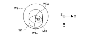
- FIG. 5 is a plan view showing a work and a target object whose attitude error directions are different from those of FIG. 5A by 90 deg.
- FIG. 5 is a plan view showing a work and a target object whose attitude error directions are different from those of FIG. 5A by 180 deg.
- FIG. 5 is a plan view showing a work and a target object whose attitude error directions are different from those of FIG. 5A by 270 deg. It is a side view which shows the position error between a work and a target object at the time of automatic adjustment of a force control parameter. It is a schematic diagram which shows the robot system which performs the face-to-face work. It is a schematic diagram which shows the robot system which performs a search work.
- FIG. 1 is a schematic diagram showing a robot system 1 that performs fitting work.
- the robot system 1 includes a robot 2, a robot control device 3 for controlling the robot 2, and a teaching operation panel 4 for an operator to manually operate the robot 2 via the robot control device 3.
- Robot 2 is a vertical articulated robot having a plurality of robot arms 21.
- the plurality of robot arms 21 are rotatably connected to each other by a plurality of drive shafts.
- the drive shaft is rotationally driven by an actuator 24 (see FIG. 2) including a servomotor controlled by the robot control device 3.
- a hand 22 and a force detector 23 are provided at the tip of the robot arm 21.
- the hand 22 grips the work by being driven and controlled by the robot control device 3.
- the work has a work W1 gripped by the hand 22 and a work W2 on the workbench 100.
- the work W1 has, for example, a cylindrical shape.
- the work W2 is a target object for fitting the work W1 by the operation of the robot 2.
- the work W2 has a columnar fitting hole MH into which the work W1 can be fitted.
- the work W2 is placed on the work table 100 so that the opening of the fitting hole MH faces upward.
- the force detector 23 is arranged near the base of the hand 22.
- the force detector 23 detects the force and the moment received by the work W1 held by the hand 22.
- the force detector 23 is composed of a force sensor. More specifically, the force detector 23 can use a 6-axis sensor capable of detecting translational forces in the X, Y, and Z axis directions and moments around those axes.
- the detection value of the force detector 23 is output to the control unit 31 of the robot control device 3.
- the robot control device 3 includes a control unit 31, an arm drive unit 32, a parameter automatic adjustment unit 33, and a storage unit 34.
- the robot control device 3 includes a function as a control device for automatically adjusting force control parameters in addition to a function as a control device for general motion control of the robot 2.
- the function for automatically adjusting the force control parameter in the robot control device 3 will be described, and the details of the function for controlling the operation of the general robot 2 will be omitted.
- the control unit 31 is a control device that outputs a movement command based on a predetermined job to the arm drive unit 32 and controls the operation of the robot 2.
- the control unit 31 corrects the position error and the posture error of the work W1 gripped by the hand 22 based on the predetermined force control parameter stored in the storage unit 34 and the detection value of the force detector 23. While controlling the force of 21, the work W1 is moved with respect to the work W2.
- the arm drive unit 32 applies a current for driving to the actuator 24 of each drive shaft of the robot 2 based on the movement command from the control unit 31. As a result, each robot arm 21 of the robot 2 is driven, and the robot 2 changes its posture in various ways.
- the robot 2 has a torque sensor 25 for detecting the torque of the actuator 24.
- the torque sensor 25 outputs the detection value of the torque of the actuator 24 to the force detector 23.
- FIG. 2 shows only one actuator 24 and one torque sensor 25. However, the set of the actuator 24 and the torque sensor 25 is provided on each of the plurality of drive shafts of the robot 2.
- the parameter automatic adjustment unit 33 controls the operation of the robot 2 via the control unit 31 and automatically adjusts the force control parameters.
- the force control parameters include a force control gain, a speed command value, a force command value, and the like, which represent the responsiveness of the force control of the robot 2.
- the automatically adjusted force control parameter is overwritten with the force control parameter (initial parameter) stored in the storage unit 34. The details of the specific adjustment operation of the force control parameter by the parameter automatic adjustment unit 33 will be described later.
- the teaching operation panel 4 is connected to the control unit 31 of the robot control device 3.
- the teaching operation panel 4 instructs the execution of various operations such as reproduction of the operation program of the robot 2, instruction of the robot 2 by a jog operation, and automatic adjustment of force control parameters by manual operation of the operator.
- the teaching operation panel 4 is connected to the control unit 31 by wire, but may be connected wirelessly.
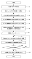
- the automatic adjustment work of the force control parameter by the parameter automatic adjustment unit 33 of the robot control device 3 will be further described with reference to the flowchart shown in FIG. 3, FIGS. 4 and 5A to 5D.
- the automatic adjustment work of the force control parameter by the parameter automatic adjustment unit 33 shown below is, for example, when the robot system 1 is initially started up, when the type of work is changed, and the hand 22 at the tip of the robot arm 21 is different. When it is exchanged for a hand having a structure, it is executed by an instruction from an operator via the teaching operation panel 4.
- the control unit 31 moves the work W1 gripped by the hand 22 with respect to the work W2 which is the target object according to a predetermined parameter automatic adjustment flow by the parameter automatic adjustment unit 33, and the fitting hole of the work W2.
- the operation of fitting to the MH is executed a plurality of times.
- the parameter automatic adjustment unit 33 reads out the initial parameters of the force control parameters from the storage unit 34 when the robot 2 is operated by the manual operation of the teaching operation panel 4 by the operator.
- the control unit 31 outputs a movement command to the arm drive unit 32 via the control unit 31 so that the work W1 gripped by the hand 22 is fitted into the fitting hole MH of the work W2.
- the first fitting operation for operating the robot 2 is executed (step S1).
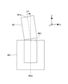
- FIG. 4 is a side view showing a state immediately before the work W1 gripped by the hand 22 is fitted into the fitting hole MH of the work W2 by the force control of the robot 2 by the initial parameter.
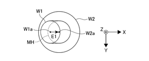
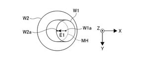
- FIG. 5A is a plan view thereof.
- the robot 2 when the robot 2 is force-controlled based on the initial parameters, the robot 2 shows a posture in which the work W1 is inclined with respect to the fitting hole MH. Specifically, the axis W1a of the work W1 is tilted by an angle E1 in the ⁇ X axis direction (left direction in FIGS. 4 and 5A) around the Y axis with respect to the axis W2a of the fitting hole MH of the work W2. There is.
- the robot 2 In order to properly fit the work W1 into the fitting hole MH, the robot 2 needs to show a posture in which the axis W1a of the work W1 and the axis W2a of the fitting hole MH match. Therefore, the angle E1 represents the posture error to be corrected by the robot 2 at the start of fitting. This angle E1 is the amount of change in the posture of the robot 2 required for properly fitting the work W1 into the fitting hole MH, that is, the amount of correction of the posture error (E).
- inv (TB) ⁇ TA is the rotation representing the correction amount (E) of the posture error. It becomes a matrix.
- inv is an inverse matrix.
- the parameter automatic adjustment unit 33 calculates the correction amount (E) of this posture error and stores it in the storage unit 34 (step S2).
- the parameter automatic adjustment unit 33 is preset with a threshold value for the amount of correction of the posture error.
- the parameter automatic adjustment unit 33 sets the posture error correction amount (E) to a predetermined value. This is because the attitude error is intentionally given when there is no attitude error or when the attitude error is too small.
- the predetermined value is, for example, a threshold value. That is, when the threshold value is set to 0.5 deg and the posture error correction amount calculated in step S2 is 0.5 deg or less, the posture error correction amount (E) is set to 0.5 deg.
- control unit 31 changes the posture error direction with the same position as when the first fitting operation is executed and the same absolute value as the correction amount (E) of the posture error of the robot 2, and the second fitting is performed.
- the operation is executed (step S3).
- the parameter automatic adjustment unit 33 executes fitting from the posture indicated by the rotation matrix of TB ⁇ T (90) ⁇ inv (TB) ⁇ TA.
- T (90) is a matrix that is rotated by 90 deg around the fitting direction (around the axis W2a of the fitting hole MH) with respect to the first fitting operation.
- the axis W1a of the work W1 is angled in the + Y axis direction (downward in FIG. 5B) around the X axis with respect to the axis W2a of the fitting hole MH of the work W2. Fitting is performed from a position tilted by E1.
- control unit 31 changes the posture error direction again with the same position as when the second fitting operation is executed and the same absolute value as the correction amount (E) of the posture error of the robot 2, and the third fitting.
- the combined operation is executed (step S4).
- the parameter automatic adjustment unit 33 executes fitting from the posture indicated by the rotation matrix of TB ⁇ T (180) ⁇ inv (TB) ⁇ TA.
- T (180) is a matrix that rotates 180 deg around the fitting direction (around the axis W2a of the fitting hole MH) with respect to the first fitting operation.
- the axis W1a of the work W1 is angled with respect to the axis W2a of the fitting hole MH of the work W2 in the + X axis direction (right direction in FIG. 5C) around the Y axis. Fitting is performed from a position tilted by E1.
- control unit 31 changes the posture error direction again with the same position as when the third fitting operation is executed and the same absolute value as the correction amount (E) of the posture error of the robot 2, and the fourth fitting.
- the combined operation is executed (step S5).
- the parameter automatic adjustment unit 33 executes fitting from the posture indicated by the rotation matrix of TB ⁇ T (270) ⁇ inv (TB) ⁇ TA.
- T (270) is a matrix that is rotated by 270 deg around the fitting direction (around the axis W2a of the fitting hole MH) with respect to the first fitting operation.
- the axis W1a of the work W1 is in the ⁇ Y axis direction (upward in FIG. 5D) around the X axis with respect to the axis W2a of the fitting hole MH of the work W2. Fitting is performed from a position tilted by the angle E1.
- the parameter automatic adjustment unit 33 records the detection value output from the force detector 23 via the control unit 31.
- the parameter automatic adjustment unit 33 obtains the vibration amount from the detection value of the force detector 23 at each fitting operation after the fitting operation in four directions (4 postures) is completed, and the data of the detected value is the most vibrating. The direction (posture) that was was selected (step S6).
- the vibration amount for example, there is a method of Fourier transforming the detected value of the force detector 23 and obtaining the amplitude of a specific frequency based on the result. Further, the vibration amount may be obtained by obtaining the maximum value or the average value of the change amount of the detection value of the force detector 23.
- step S6 the parameter automatic adjustment unit 33 selects the direction (attitude) in which the detection value data of the force detector 23 is the most vibrating, and then adjusts the force only based on the attitude error in that direction (attitude).
- Parameters 1 to N are obtained (step S7), and each force control parameter is changed so as to improve the performance (step S8).
- N is the number of types of force control parameters.
- the types of force control parameters are force control gain, speed command value, force command value, and the like.
- the force control parameters may be adjusted one by one, or a plurality of types of parameters may be adjusted at the same time.
- step S8 After changing the force control parameter in step S8 in this way, the control unit 31 again due to the posture error in the most vibrating direction (posture) among the fitting operations in the four directions (four postures).
- the robot 2 is operated so as to fit the work W1 into the fitting hole MH of the work W2 (step S9).
- the robot 2 tends to become unstable such as large vibration.
- the force control gain is increased, the response to the generated force becomes faster, so that the posture error at the time of fitting is corrected faster, and the time required for fitting becomes shorter.
- the force control gain is increased too much, the noise may be amplified and the robot 2 may oscillate. Therefore, the parameter automatic adjustment unit 33 obtains the vibration amount from the detection value of the force detector 23 by the above method after executing the fitting operation in step S9, and determines whether or not the robot 2 is oscillating (step). S10). Whether or not the robot 2 oscillates is determined based on whether the vibration amount is larger than the vibration amount at the time of the previous automatic parameter adjustment, or the vibration amount exceeds a preset threshold value. Can be done.
- step S10 If it is determined in step S10 that the robot 2 is not oscillating (step S10; NO), the parameter automatic adjustment unit 33 returns to the process from step S8. That is, the parameter automatic adjustment unit 33 changes the force control parameter so that the performance of the force control parameter is further improved, and then re-executes the fitting operation with the most vibrating posture error. Then, in step S10, it is determined again whether or not the robot 2 is oscillating. The processes of steps S8 and S9 are repeated until it is determined in step S10 that the robot 2 is oscillating.
- step S10 when it is determined in step S10 that the robot 2 is oscillating (step S10; YES), the parameter automatic adjustment unit 33 returns the changed force control parameter to the previous value (step S11). ..
- the parameter automatic adjustment unit 33 outputs the set force control parameter to the storage unit 34, overwrites and saves the set, and then ends the automatic adjustment operation of the force control parameter.
- the parameter automatic adjustment unit 33 automatically adjusts the force control parameters by executing the movement of the work W1 from a plurality of posture error directions.
- the parameter automatic adjustment unit 33 adjusts the force control parameter under the condition of the posture error that is the most vibrating among the plurality of posture error directions.
- the robot 2 performs the fitting operation based on the force control parameter that can stably perform the fitting operation under the severest posture error condition, so that the robot 2 performs the fitting operation even under the condition of other loose posture errors.
- a stable fitting operation can be performed. Therefore, according to the robot system 1 and the robot control device 3, it is possible to automatically adjust the optimum force control parameters that do not cause the oscillation of the robot 2 or the failure of the fitting operation in the force control at the time of production.
- the robot arm 21 has an actuator 24 for driving the robot arm 21 and a torque sensor 25 for detecting the torque of the actuator 24.
- the force detector 23 has a work W1 based on the detection value of the torque sensor 25. The force and moment received are detected. Therefore, the force and moment received by the work W1 can be easily detected from the torque of the actuator 24.
- the force detector 23 may detect the force and the moment received by the work W1 based on the current value applied to the actuator 24. According to this, since the torque sensor 25 does not necessarily have to be provided, the configuration of the robot 2 can be simplified.
- the parameter automatic adjustment unit 33 automatically adjusts the force control parameter by executing the movement of the work W1 from a plurality of posture error directions.
- the parameter automatic adjustment unit 33 may automatically adjust the force control parameter by executing the movement of the work W1 from both a plurality of position error directions and posture error directions.
- the robot 2 when the robot 2 is force-controlled based on the initial parameters, the robot 2 shows a posture in which the work W1 is inclined with respect to the fitting hole MH, and the fitting hole MH is shown. It is slightly offset from the center to the side. Specifically, the axis W1a of the work W1 is tilted by an angle E1 in the ⁇ X axis direction (left direction in FIG.
- the work W1 is displaced by a distance E2 in the ⁇ X axis direction with respect to the axis W2a of the fitting hole MH.
- the moving operation of the work W1 with respect to the work W2 by the robot 2 is a fitting operation of fitting the work W1 into the fitting hole MH of the work W2
- the movement operation of the work W1 with respect to the work W2 by the robot 2 is a face-to-face operation in which the work W1 gripped by the hand 22 is faced with the plane SF of the work W2 as in the robot system 1A shown in FIG. You may.
- the moving operation of the work W1 with respect to the work W2 by the robot 2 is a search operation for searching the work W1 so as to match the shape and phase of the engaging hole EH of the work W2, as in the robot system 1B shown in FIG. May be.
- the movement of the work W1 with respect to the work W2 at the time of automatic adjustment of the force control parameter is executed from four directions (four postures) changed by 90 deg.
- the changing direction (posture) is not limited to four, and may be two or more directions (posture).
- the angle to be changed is not limited to 90 deg.
- the parameter automatic adjustment unit 33 that automatically adjusts the force control parameters is provided in the robot control device 3 that is electrically connected to the robot 2 in order to control the operation of the robot 2.
- the function of the parameter automatic adjustment unit 33 of the robot control device 3 or all the functions may be realized by an external terminal such as a PC (personal computer) and a tablet terminal.
Landscapes
- Engineering & Computer Science (AREA)
- Robotics (AREA)
- Mechanical Engineering (AREA)
- Human Computer Interaction (AREA)
- Manipulator (AREA)
Abstract
Description
2 ロボット
21 ロボットアーム
22 ハンド
23 力検出器
24 アクチュエータ
25 トルクセンサ
3 ロボット制御装置
31 制御部
33 パラメータ自動調整部
W1 ワーク
W2 ワーク(目標対象物)
MH 嵌合穴
SF 平面
EH 係合穴
Claims (9)
- ワークを把持するハンドを先端に有するロボットアームと、
前記ハンドに把持された前記ワークが受ける力及びモーメントを検出する力検出器と、
所定の力制御パラメータ及び前記力検出器の検出値に基づいて、前記ワークの位置誤差及び姿勢誤差を修正するように前記ロボットアームの力制御を行いながら、前記ハンドに把持された前記ワークを目標対象物に対して移動させる制御装置と、を備え、
前記制御装置は、前記目標対象物に対する前記ワークの移動を複数回実行することによって、前記力制御パラメータを自動調整するパラメータ自動調整部を有し、
前記パラメータ自動調整部は、前記目標対象物に対する前記ワークの移動を、複数の位置誤差方向及び複数の姿勢誤差方向のうちの少なくとも前記複数の姿勢誤差方向から実行することによって、前記力制御パラメータを自動調整する、ロボットシステム。 - 前記パラメータ自動調整部は、前記目標対象物に対する前記ワークの移動を、複数の位置誤差方向及び複数の姿勢誤差方向のうちの少なくとも前記複数の姿勢誤差方向から実行し、そのうちの前記力検出器の検出値が最も振動的であった条件によって前記力制御パラメータを自動調整する、請求項1に記載のロボットシステム。
- 前記目標対象物に対する前記ワークの移動動作は、前記ワークを前記目標対象物が有する嵌合穴に嵌合させる嵌合動作、前記ワークを前記目標対象物の平面に対して面合せする面合せ動作、及び前記ワークを前記目標対象物が有する係合穴の形状に一致するように探索させる探索動作のうちのいずれかである、請求項1又は2に記載のロボットシステム。
- 前記力検出器は、力覚センサである、請求項1~3のいずれか1項に記載のロボットシステム。
- 前記ロボットアームは、前記ロボットアームを駆動するアクチュエータと、前記アクチュエータのトルクを検出するトルクセンサと、を有し、
前記力検出器は、前記トルクセンサの検出値に基づいて、前記ワークが受ける力及びモーメントを検出する、請求項1~4のいずれか1項に記載のロボットシステム。 - 前記ロボットアームは、前記ロボットアームを駆動するアクチュエータを有し、
前記力検出器は、前記アクチュエータに印加される電流値に基づいて、前記ワークが受ける力及びモーメントを検出する、請求項1~4のいずれか1項に記載のロボットシステム。 - ワークを把持するハンドを先端に有するロボットアームの動作を制御して前記ワークを目標対象物に向けて移動させ、所定の力制御パラメータと、前記ハンドに把持された前記ワークが受ける力及びモーメントを検出する力検出器の検出値と、に基づいて、前記目標対象物に対する前記ワークの位置誤差及び姿勢誤差を修正するように前記ロボットアームの力制御を行うロボット制御装置であって、
前記対象物に対する前記ワークの移動を複数回実行することによって、前記力制御パラメータを自動調整するパラメータ自動調整部を有し、
前記パラメータ自動調整部は、前記目標対象物に対する前記ワークの移動を、複数の位置誤差方向及び複数の姿勢誤差方向のうちの少なくとも前記複数の姿勢誤差方向から実行することによって、前記力制御パラメータを自動調整する、ロボット制御装置。 - 前記パラメータ自動調整部は、前記目標対象物に対する前記ワークの移動を、複数の位置誤差方向及び複数の姿勢誤差方向のうちの少なくとも前記複数の姿勢誤差方向から実行し、そのうちの前記力検出器の検出値が最も振動的であった条件によって前記力制御パラメータを自動調整する、請求項7に記載のロボット制御装置。
- 前記目標対象物に対する前記ワークの移動動作は、前記ワークを前記目標対象物が有する穴に嵌合させる嵌合動作、前記ワークを前記目標対象物の平面に対して面合せする面合せ動作、及び前記ワークを前記目標対象物が有する係合穴の形状に一致するように探索させる探索動作のうちのいずれかである、請求項7又は8に記載のロボット制御装置。
Priority Applications (5)
| Application Number | Priority Date | Filing Date | Title |
|---|---|---|---|
| US18/004,407 US12337479B2 (en) | 2020-07-31 | 2021-07-26 | Robot system and robot control device |
| JP2022540282A JP7392161B2 (ja) | 2020-07-31 | 2021-07-26 | ロボットシステム及びロボット制御装置 |
| CN202180060367.0A CN116133803A (zh) | 2020-07-31 | 2021-07-26 | 机器人系统和机器人控制装置 |
| DE112021004052.9T DE112021004052B4 (de) | 2020-07-31 | 2021-07-26 | Robotersystem und Robotersteuerungsvorrichtung |
| JP2023197630A JP7575559B2 (ja) | 2020-07-31 | 2023-11-21 | 制御装置 |
Applications Claiming Priority (2)
| Application Number | Priority Date | Filing Date | Title |
|---|---|---|---|
| JP2020130055 | 2020-07-31 | ||
| JP2020-130055 | 2020-07-31 |
Publications (1)
| Publication Number | Publication Date |
|---|---|
| WO2022024976A1 true WO2022024976A1 (ja) | 2022-02-03 |
Family
ID=80036351
Family Applications (1)
| Application Number | Title | Priority Date | Filing Date |
|---|---|---|---|
| PCT/JP2021/027495 Ceased WO2022024976A1 (ja) | 2020-07-31 | 2021-07-26 | ロボットシステム及びロボット制御装置 |
Country Status (5)
| Country | Link |
|---|---|
| US (1) | US12337479B2 (ja) |
| JP (2) | JP7392161B2 (ja) |
| CN (1) | CN116133803A (ja) |
| DE (1) | DE112021004052B4 (ja) |
| WO (1) | WO2022024976A1 (ja) |
Cited By (4)
| Publication number | Priority date | Publication date | Assignee | Title |
|---|---|---|---|---|
| WO2024084544A1 (ja) * | 2022-10-17 | 2024-04-25 | ファナック株式会社 | ロボット制御装置 |
| WO2024176466A1 (ja) * | 2023-02-24 | 2024-08-29 | ファナック株式会社 | 制御装置及びロボットシステム |
| US20250010469A1 (en) * | 2023-07-04 | 2025-01-09 | Hitachi, Ltd. | Robot control device and robot control method |
| US12330305B2 (en) * | 2022-03-11 | 2025-06-17 | Omron Corporation | Robot system and method for controlling same |
Families Citing this family (6)
| Publication number | Priority date | Publication date | Assignee | Title |
|---|---|---|---|---|
| US20220134557A1 (en) * | 2020-10-30 | 2022-05-05 | Sintokogio, Ltd. | Control device, robot control system, program, and control method |
| JP7600639B2 (ja) * | 2020-11-26 | 2024-12-17 | セイコーエプソン株式会社 | ロボットシステム、およびロボットシステムにおける力制御パラメーターの調整方法 |
| JP7666223B2 (ja) | 2021-08-18 | 2025-04-22 | 新東工業株式会社 | 自動塗布装置、及び自動塗布方法 |
| JP7799275B2 (ja) | 2022-03-04 | 2026-01-15 | 新東工業株式会社 | ロボット、及び、その制御方法 |
| GB2627511B (en) * | 2023-02-24 | 2025-05-07 | Airbus Operations Ltd | Self aligning system |
| CN120735050B (zh) * | 2025-09-02 | 2025-11-07 | 西安工业大学 | 一种具有感知反馈调节的机械臂自动化控制方法 |
Citations (2)
| Publication number | Priority date | Publication date | Assignee | Title |
|---|---|---|---|---|
| JP2014233814A (ja) * | 2013-06-04 | 2014-12-15 | 株式会社安川電機 | ロボット教示補助装置、ロボットシステムおよびロボット教示方法 |
| WO2019017416A1 (ja) * | 2017-07-20 | 2019-01-24 | キヤノン株式会社 | 作業用ロボット、作業用ロボットの制御方法 |
Family Cites Families (14)
| Publication number | Priority date | Publication date | Assignee | Title |
|---|---|---|---|---|
| JP4390126B2 (ja) * | 2002-06-17 | 2009-12-24 | 独立行政法人科学技術振興機構 | ロボット指関節等に応用できる高感度トルクセンサ調整方法 |
| US7181314B2 (en) * | 2003-11-24 | 2007-02-20 | Abb Research Ltd. | Industrial robot with controlled flexibility and simulated force for automated assembly |
| US9008836B2 (en) * | 2007-01-09 | 2015-04-14 | Abb Inc. | Method and system for robotic assembly parameter optimization |
| JP2008290228A (ja) * | 2007-04-24 | 2008-12-04 | Fanuc Ltd | 嵌合装置 |
| US20100257986A1 (en) * | 2009-04-09 | 2010-10-14 | James Borg | Apparatus and method for robotic deburr and material removal |
| WO2011036865A1 (ja) * | 2009-09-28 | 2011-03-31 | パナソニック株式会社 | ロボットアームの制御装置及び制御方法、ロボット、ロボットアームの制御プログラム、及び、ロボットアーム制御用集積電子回路 |
| JP4962551B2 (ja) * | 2009-10-20 | 2012-06-27 | 株式会社安川電機 | ロボットシステムおよびロボットシステムの制御方法 |
| JP4837113B2 (ja) * | 2010-03-18 | 2011-12-14 | ファナック株式会社 | ロボットを用いた嵌合装置 |
| JP5505138B2 (ja) * | 2010-07-05 | 2014-05-28 | 株式会社安川電機 | ロボット装置およびロボット装置による把持方法 |
| JP2014128857A (ja) | 2012-12-28 | 2014-07-10 | Yaskawa Electric Corp | ロボット教示システムおよびロボット教示方法 |
| CN105382839A (zh) * | 2014-08-25 | 2016-03-09 | 精工爱普生株式会社 | 机器人以及机器人系统 |
| JP6651707B2 (ja) * | 2015-04-10 | 2020-02-19 | セイコーエプソン株式会社 | ロボット、制御装置、及び制御方法 |
| US10363661B2 (en) * | 2016-07-27 | 2019-07-30 | Seiko Epson Corporation | Control device, robot, and robot system |
| US10213925B2 (en) * | 2016-09-09 | 2019-02-26 | The Board Of Trustees Of The Leland Stanford Junior University | Workpiece contact state estimating device and workpiece contact state estimation method |
-
2021
- 2021-07-26 US US18/004,407 patent/US12337479B2/en active Active
- 2021-07-26 JP JP2022540282A patent/JP7392161B2/ja active Active
- 2021-07-26 WO PCT/JP2021/027495 patent/WO2022024976A1/ja not_active Ceased
- 2021-07-26 CN CN202180060367.0A patent/CN116133803A/zh active Pending
- 2021-07-26 DE DE112021004052.9T patent/DE112021004052B4/de active Active
-
2023
- 2023-11-21 JP JP2023197630A patent/JP7575559B2/ja active Active
Patent Citations (2)
| Publication number | Priority date | Publication date | Assignee | Title |
|---|---|---|---|---|
| JP2014233814A (ja) * | 2013-06-04 | 2014-12-15 | 株式会社安川電機 | ロボット教示補助装置、ロボットシステムおよびロボット教示方法 |
| WO2019017416A1 (ja) * | 2017-07-20 | 2019-01-24 | キヤノン株式会社 | 作業用ロボット、作業用ロボットの制御方法 |
Cited By (5)
| Publication number | Priority date | Publication date | Assignee | Title |
|---|---|---|---|---|
| US12330305B2 (en) * | 2022-03-11 | 2025-06-17 | Omron Corporation | Robot system and method for controlling same |
| WO2024084544A1 (ja) * | 2022-10-17 | 2024-04-25 | ファナック株式会社 | ロボット制御装置 |
| WO2024176466A1 (ja) * | 2023-02-24 | 2024-08-29 | ファナック株式会社 | 制御装置及びロボットシステム |
| US20250010469A1 (en) * | 2023-07-04 | 2025-01-09 | Hitachi, Ltd. | Robot control device and robot control method |
| US12611772B2 (en) * | 2023-07-04 | 2026-04-28 | Hitachi, Ltd. | Robot control device and robot control method |
Also Published As
| Publication number | Publication date |
|---|---|
| JPWO2022024976A1 (ja) | 2022-02-03 |
| JP2024009167A (ja) | 2024-01-19 |
| US12337479B2 (en) | 2025-06-24 |
| US20230278205A1 (en) | 2023-09-07 |
| DE112021004052T5 (de) | 2023-08-24 |
| JP7392161B2 (ja) | 2023-12-05 |
| JP7575559B2 (ja) | 2024-10-29 |
| CN116133803A (zh) | 2023-05-16 |
| DE112021004052B4 (de) | 2025-07-10 |
Similar Documents
| Publication | Publication Date | Title |
|---|---|---|
| JP7392161B2 (ja) | ロボットシステム及びロボット制御装置 | |
| JP4271249B2 (ja) | 嵌合装置 | |
| US9718187B2 (en) | Robot controlling method, robot apparatus, program, recording medium, and method for manufacturing assembly component | |
| US10618164B2 (en) | Robot system having learning control function and learning control method | |
| US10350749B2 (en) | Robot control device having learning control function | |
| CN110405753B (zh) | 机器人控制装置以及机器人系统 | |
| US9868209B2 (en) | Robot | |
| CN110315517B (zh) | 机器人系统和控制方法 | |
| US20100262289A1 (en) | Device utilizing a pid controller,control method thereof, and robot utilizing the controller | |
| JP6693939B2 (ja) | ロボットシステム | |
| US20220032448A1 (en) | Teaching method and robot system | |
| CN114571447B (zh) | 机器人控制装置 | |
| JP2019084650A (ja) | ロボット装置及び組立品の製造方法 | |
| JP7543160B2 (ja) | バネ定数補正装置、該方法および該プログラム | |
| US12162168B2 (en) | Method for controlling robot, robot system, and storage medium | |
| US12194633B2 (en) | Method for controlling robot, robot system, and storage medium | |
| JP5299255B2 (ja) | ロボット制御装置 | |
| JP7624850B2 (ja) | ロボットアームの制御装置、制御方法、システム、及びプログラム | |
| JP2007066001A (ja) | ロボットの制御装置 | |
| JP4631856B2 (ja) | 作業補助装置、作業補助方法及びその作業に使用するワーク回転装置 | |
| JP7113200B2 (ja) | ロボット制御方法及びロボット制御装置 | |
| WO2024084544A1 (ja) | ロボット制御装置 | |
| JP5262880B2 (ja) | ロボット制御装置 | |
| JP2020179465A (ja) | 制御装置、制御方法、およびロボットシステム | |
| JP2024071866A (ja) | ロボットの制御方法およびロボットシステム |
Legal Events
| Date | Code | Title | Description |
|---|---|---|---|
| 121 | Ep: the epo has been informed by wipo that ep was designated in this application |
Ref document number: 21848983 Country of ref document: EP Kind code of ref document: A1 |
|
| ENP | Entry into the national phase |
Ref document number: 2022540282 Country of ref document: JP Kind code of ref document: A |
|
| 122 | Ep: pct application non-entry in european phase |
Ref document number: 21848983 Country of ref document: EP Kind code of ref document: A1 |
|
| WWG | Wipo information: grant in national office |
Ref document number: 18004407 Country of ref document: US |
|
| WWG | Wipo information: grant in national office |
Ref document number: 112021004052 Country of ref document: DE |