WO2022024713A1 - Battery case, and battery pack - Google Patents
Battery case, and battery pack Download PDFInfo
- Publication number
- WO2022024713A1 WO2022024713A1 PCT/JP2021/025881 JP2021025881W WO2022024713A1 WO 2022024713 A1 WO2022024713 A1 WO 2022024713A1 JP 2021025881 W JP2021025881 W JP 2021025881W WO 2022024713 A1 WO2022024713 A1 WO 2022024713A1
- Authority
- WO
- WIPO (PCT)
- Prior art keywords
- case
- battery
- gas
- inner case
- gas discharge
- Prior art date
Links
Images


Classifications
-
- H—ELECTRICITY
- H01—ELECTRIC ELEMENTS
- H01M—PROCESSES OR MEANS, e.g. BATTERIES, FOR THE DIRECT CONVERSION OF CHEMICAL ENERGY INTO ELECTRICAL ENERGY
- H01M50/00—Constructional details or processes of manufacture of the non-active parts of electrochemical cells other than fuel cells, e.g. hybrid cells
- H01M50/30—Arrangements for facilitating escape of gases
- H01M50/394—Gas-pervious parts or elements
-
- H—ELECTRICITY
- H01—ELECTRIC ELEMENTS
- H01M—PROCESSES OR MEANS, e.g. BATTERIES, FOR THE DIRECT CONVERSION OF CHEMICAL ENERGY INTO ELECTRICAL ENERGY
- H01M50/00—Constructional details or processes of manufacture of the non-active parts of electrochemical cells other than fuel cells, e.g. hybrid cells
- H01M50/30—Arrangements for facilitating escape of gases
- H01M50/317—Re-sealable arrangements
-
- H—ELECTRICITY
- H01—ELECTRIC ELEMENTS
- H01M—PROCESSES OR MEANS, e.g. BATTERIES, FOR THE DIRECT CONVERSION OF CHEMICAL ENERGY INTO ELECTRICAL ENERGY
- H01M10/00—Secondary cells; Manufacture thereof
- H01M10/60—Heating or cooling; Temperature control
- H01M10/61—Types of temperature control
- H01M10/613—Cooling or keeping cold
-
- H—ELECTRICITY
- H01—ELECTRIC ELEMENTS
- H01M—PROCESSES OR MEANS, e.g. BATTERIES, FOR THE DIRECT CONVERSION OF CHEMICAL ENERGY INTO ELECTRICAL ENERGY
- H01M10/00—Secondary cells; Manufacture thereof
- H01M10/60—Heating or cooling; Temperature control
- H01M10/64—Heating or cooling; Temperature control characterised by the shape of the cells
- H01M10/643—Cylindrical cells
-
- H—ELECTRICITY
- H01—ELECTRIC ELEMENTS
- H01M—PROCESSES OR MEANS, e.g. BATTERIES, FOR THE DIRECT CONVERSION OF CHEMICAL ENERGY INTO ELECTRICAL ENERGY
- H01M50/00—Constructional details or processes of manufacture of the non-active parts of electrochemical cells other than fuel cells, e.g. hybrid cells
- H01M50/20—Mountings; Secondary casings or frames; Racks, modules or packs; Suspension devices; Shock absorbers; Transport or carrying devices; Holders
- H01M50/204—Racks, modules or packs for multiple batteries or multiple cells
- H01M50/207—Racks, modules or packs for multiple batteries or multiple cells characterised by their shape
- H01M50/209—Racks, modules or packs for multiple batteries or multiple cells characterised by their shape adapted for prismatic or rectangular cells
-
- H—ELECTRICITY
- H01—ELECTRIC ELEMENTS
- H01M—PROCESSES OR MEANS, e.g. BATTERIES, FOR THE DIRECT CONVERSION OF CHEMICAL ENERGY INTO ELECTRICAL ENERGY
- H01M50/00—Constructional details or processes of manufacture of the non-active parts of electrochemical cells other than fuel cells, e.g. hybrid cells
- H01M50/20—Mountings; Secondary casings or frames; Racks, modules or packs; Suspension devices; Shock absorbers; Transport or carrying devices; Holders
- H01M50/204—Racks, modules or packs for multiple batteries or multiple cells
- H01M50/207—Racks, modules or packs for multiple batteries or multiple cells characterised by their shape
- H01M50/213—Racks, modules or packs for multiple batteries or multiple cells characterised by their shape adapted for cells having curved cross-section, e.g. round or elliptic
-
- H—ELECTRICITY
- H01—ELECTRIC ELEMENTS
- H01M—PROCESSES OR MEANS, e.g. BATTERIES, FOR THE DIRECT CONVERSION OF CHEMICAL ENERGY INTO ELECTRICAL ENERGY
- H01M50/00—Constructional details or processes of manufacture of the non-active parts of electrochemical cells other than fuel cells, e.g. hybrid cells
- H01M50/20—Mountings; Secondary casings or frames; Racks, modules or packs; Suspension devices; Shock absorbers; Transport or carrying devices; Holders
- H01M50/233—Mountings; Secondary casings or frames; Racks, modules or packs; Suspension devices; Shock absorbers; Transport or carrying devices; Holders characterised by physical properties of casings or racks, e.g. dimensions
- H01M50/24—Mountings; Secondary casings or frames; Racks, modules or packs; Suspension devices; Shock absorbers; Transport or carrying devices; Holders characterised by physical properties of casings or racks, e.g. dimensions adapted for protecting batteries from their environment, e.g. from corrosion
-
- H—ELECTRICITY
- H01—ELECTRIC ELEMENTS
- H01M—PROCESSES OR MEANS, e.g. BATTERIES, FOR THE DIRECT CONVERSION OF CHEMICAL ENERGY INTO ELECTRICAL ENERGY
- H01M50/00—Constructional details or processes of manufacture of the non-active parts of electrochemical cells other than fuel cells, e.g. hybrid cells
- H01M50/20—Mountings; Secondary casings or frames; Racks, modules or packs; Suspension devices; Shock absorbers; Transport or carrying devices; Holders
- H01M50/271—Lids or covers for the racks or secondary casings
-
- H—ELECTRICITY
- H01—ELECTRIC ELEMENTS
- H01M—PROCESSES OR MEANS, e.g. BATTERIES, FOR THE DIRECT CONVERSION OF CHEMICAL ENERGY INTO ELECTRICAL ENERGY
- H01M50/00—Constructional details or processes of manufacture of the non-active parts of electrochemical cells other than fuel cells, e.g. hybrid cells
- H01M50/30—Arrangements for facilitating escape of gases
- H01M50/308—Detachable arrangements, e.g. detachable vent plugs or plug systems
-
- H—ELECTRICITY
- H01—ELECTRIC ELEMENTS
- H01M—PROCESSES OR MEANS, e.g. BATTERIES, FOR THE DIRECT CONVERSION OF CHEMICAL ENERGY INTO ELECTRICAL ENERGY
- H01M50/00—Constructional details or processes of manufacture of the non-active parts of electrochemical cells other than fuel cells, e.g. hybrid cells
- H01M50/30—Arrangements for facilitating escape of gases
- H01M50/35—Gas exhaust passages comprising elongated, tortuous or labyrinth-shaped exhaust passages
- H01M50/358—External gas exhaust passages located on the battery cover or case
-
- H—ELECTRICITY
- H01—ELECTRIC ELEMENTS
- H01M—PROCESSES OR MEANS, e.g. BATTERIES, FOR THE DIRECT CONVERSION OF CHEMICAL ENERGY INTO ELECTRICAL ENERGY
- H01M50/00—Constructional details or processes of manufacture of the non-active parts of electrochemical cells other than fuel cells, e.g. hybrid cells
- H01M50/30—Arrangements for facilitating escape of gases
- H01M50/35—Gas exhaust passages comprising elongated, tortuous or labyrinth-shaped exhaust passages
- H01M50/367—Internal gas exhaust passages forming part of the battery cover or case; Double cover vent systems
-
- Y—GENERAL TAGGING OF NEW TECHNOLOGICAL DEVELOPMENTS; GENERAL TAGGING OF CROSS-SECTIONAL TECHNOLOGIES SPANNING OVER SEVERAL SECTIONS OF THE IPC; TECHNICAL SUBJECTS COVERED BY FORMER USPC CROSS-REFERENCE ART COLLECTIONS [XRACs] AND DIGESTS
- Y02—TECHNOLOGIES OR APPLICATIONS FOR MITIGATION OR ADAPTATION AGAINST CLIMATE CHANGE
- Y02E—REDUCTION OF GREENHOUSE GAS [GHG] EMISSIONS, RELATED TO ENERGY GENERATION, TRANSMISSION OR DISTRIBUTION
- Y02E60/00—Enabling technologies; Technologies with a potential or indirect contribution to GHG emissions mitigation
- Y02E60/10—Energy storage using batteries
Definitions
- This disclosure relates to battery cases and battery packs.
- Patent Document 1 This battery pack has a duct for circulating the gas released from the battery when the battery overheats. This battery pack lowers the temperature of the gas in its duct and discharges the low-temperature gas to the outside, thereby ensuring the safety of the area around the battery pack in the event of abnormal heat generation of the battery.
- an object of the present disclosure is to provide a battery case and a battery pack which not only can efficiently cool the gas released from the battery when the battery abnormally generates heat, but also have a simple structure and can suppress the manufacturing cost. There is something in it.
- the battery case according to the present disclosure has a battery accommodating chamber for accommodating a plurality of batteries, and discharges the gas generated by the batteries accommodated in the battery accommodating chamber to the outside of the battery accommodating chamber.
- An inner case including an inner case, an outer case including an outer gas discharging part having an inner case accommodating chamber for accommodating the inner case, and an inner case extending from the outer surface of the inner case to the inner surface of the outer case.
- the case is positioned with respect to the outer case, and is defined by a plurality of inner case positioning portions arranged at intervals from each other, an outer surface of the inner case, an inner surface of the outer case, and a plurality of inner case positioning portions. It is provided with one or more gas guide passages for guiding gas from the inner gas discharge portion side to the outer gas discharge portion side.
- the inner gas discharging portion may be configured at least one of one or more inner holes and one or more inner damaged portions that are damaged when the internal pressure of the battery accommodating chamber becomes the first predetermined pressure or more.
- the outer gas discharge portion may be configured at least one of one or more outer holes and one or more outer damaged portions that are damaged when the internal pressure of the inner case accommodating chamber becomes a second predetermined pressure or more.
- the first predetermined pressure may be the same as the second predetermined pressure, or may be a pressure different from the second predetermined pressure.
- the battery pack according to the present disclosure includes a battery case according to the present disclosure and a plurality of batteries arranged in the battery storage chamber of the battery case.
- the present disclosure it is possible to realize a battery case and a battery pack that not only can efficiently cool the gas released from the battery when the battery overheats abnormally, but also have a simple structure and can suppress the manufacturing cost.
- FIG. 3 is a cross-sectional view taken along the line AA of FIG.
- FIG. 2 is a cross-sectional view taken along the line BB of FIG.
- FIG. 3 is a plan view of the inner case of the battery pack when viewed from one side in the height direction (thickness direction) indicated by the arrow D in FIG.
- It is a top view corresponding to FIG. 4 in the inner case provided in the battery pack of 3rd Embodiment.
- It is sectional drawing corresponding to FIG. 2 in the battery pack of 4th Embodiment.
- the X direction is the battery.
- the longitudinal direction of the pack 1,101,401 (outer case 2,102,402) is shown, and the Y direction indicates the width direction (short direction) of the battery pack 1 (outer case 2,102,402), and the Z direction.
- the X, Y, and Z directions are orthogonal to each other.
- the same components are designated by the same reference numerals in the drawings, and duplicate description will be omitted.
- the description of the same effects and modifications as those of the first embodiment will be omitted.
- FIG. 1 is a perspective view of the battery pack 1 according to the first embodiment of the present disclosure.
- FIG. 2 is a cross-sectional view taken along the line AA of FIG. 1 (a cross-sectional view when the battery pack 1 is cut along an XZ plane passing through the center in the Y direction).
- FIG. 3 is a cross-sectional view taken along the line BB of FIG. 1 (a cross-sectional view of the battery pack 1 when a portion of the battery pack 1 that is neither the center nor the end thereof is cut along the YZ plane).
- the battery pack 1 includes an outer case 2 having a substantially rectangular parallelepiped shape.
- the outer case 2 is made of, for example, a metal material or a resin material.
- the outer case 2 has one outer gas discharge hole 3 as an example of the outer gas discharge portion at one end in the X direction.
- the battery pack 1 further includes a mesh-like (mesh-like) discharge hole covering member 4 made of metal, resin, or the like.
- the discharge hole covering member 4 is fixed to the outer case 2 so as to close the outer gas discharge hole 3 by a fixing means, for example, an adhesive or a welded portion.
- the discharge hole covering member 4 does not have to be mesh-shaped, and may be made of an air-permeable waterproof material that allows exhaust gas to pass through and blocks liquids such as water from the outside, for example, Gore-Tex (registered trademark). good.
- the battery pack 1 further includes an inner case 5, a block-shaped positioning member 6 made of an elastic material such as rubber, and a plurality of cylindrical secondary batteries as an example of the plurality of batteries.
- a battery 7 The battery pack 1 includes a battery case 8 and a plurality of batteries 7, and the battery case 8 includes an inner case 5, an outer case 2, a discharge hole covering member 4, and a positioning member 6.
- the battery 7 of the present embodiment is composed of a typical secondary battery, for example, a lithium ion battery, a lithium secondary battery, a Nikado battery, a nickel hydrogen battery, or the like, and is a battery included in the battery pack of the present disclosure. May be composed of a primary battery, for example, a manganese battery or an alkaline battery. Further, the battery included in the battery pack of the present disclosure is not limited to the primary battery and the secondary battery, and may not be a cylindrical battery, for example, a square battery, a pouch type battery, or the like.
- the inner case 5 has a battery accommodating chamber 11 for accommodating a plurality of batteries 7.
- the inner case 5 has an inner case main body 5a and a flat plate-shaped lid portion 5b.
- the inner case main body 5a has a first recess 11a for accommodating a plurality of batteries 7 in the axial direction, and has an opening only on the other side in the X direction (one in the axial direction of the battery 7). Then, after accommodating the plurality of batteries 7 in the first recess 11a of the inner case main body 5a, the lid portion 5b is closed to the opening on the other side of the inner case main body 5a in the X direction so as to close the opening of the inner case main body 5a in the X direction.
- the lid portion 5b may be integrally formed with the inner case main body 5a.
- the inner case main body 5a is divided into a plurality of members, and the inner case main body 5a is assembled after accommodating the plurality of batteries 7. To.
- the battery accommodating chamber 11 is thereby defined by the inner case main body 5a and the lid portion 5b.
- the inner case main body 5a may have a battery holder, and the battery 7 may be housed in the battery holder. Alternatively, the battery 7 may be fixed to the inner surface of the first recess 11a of the inner case main body 5a with double-sided tape or an adhesive.
- the lid portion 5b has one inner gas discharge hole 12 as an example of the inner gas discharge portion.
- the inner gas discharge hole 12 extends in the X direction (axial direction of the battery 7) and penetrates the lid portion 5b.
- the inner gas discharge hole 12 is provided to discharge the gas generated when the battery 7 fixed to the battery storage chamber 11 abnormally generates heat to the outside of the battery storage chamber 11.
- the inner case 5 is housed in the inner case storage chamber 14 provided in the outer case 2.
- the outer case 2 has an outer case main body 2a and a flat plate-shaped lid 2b, and the outer case main body 2a has a second recess 14a for accommodating the inner case 5, and only one side in the X direction. It has an opening (the other in the axial direction of the battery 7).
- the outer case main body 2a has a plurality of inner case locking pieces 2c projecting inside the inner case accommodating chamber 14 in a direction orthogonal to the X direction (Z direction) on one side of the outer case main body 2a in the X direction.
- the plurality of inner case locking pieces 2c are located at intervals in the X direction with respect to the inner surface 13 on one side in the X direction of the outer case main body 2a.
- the plurality of inner case locking pieces 2c have a flat plate shape, and the plurality of inner case locking pieces 2c are located at intervals from each other.
- the end faces 16 on the other side in the X direction of the plurality of inner case locking pieces 2c are located on substantially the same plane on the YZ plane formed by the Y direction and the Z direction.
- the inner case 5 having the lid portion 5b fixed to the inner case main body 5a while accommodating the plurality of batteries 7 is relatively moved to one side in the X direction indicated by the arrow C in FIG. 2 with respect to the outer case main body 2a.
- the inner case 5 is housed in the second recess 14a of the outer case main body 2a until the end surface on one side in the X direction abuts on the inner case locking piece 2c.
- the block-shaped positioning member 6 is pushed into the second recess 14a until it comes into contact with the end surface of the inner case 5 on the other side in the X direction, and then the lid portion 2b is closed the opening of the second recess 14a so that the outer case main body is closed.
- a fixing means for example, a fastening member (not shown) such as a screw.
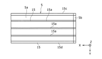
- the inner case 5 extends from the outer surface thereof to the inner surface of the outer case 2, positions the inner case 5 with respect to the outer case 2, and has a plurality of ribs 15 arranged at intervals from each other.
- the plurality of ribs 15 extend in the height direction (Z direction) of the battery pack 1 and extend in the Z direction with one or more first ribs 15a that come into contact with the inner surface on one side of the Z direction in the outer case 2.
- the outer case 2 includes one or more second ribs 15b that come into contact with the inner surface on the other side in the Z direction.
- the plurality of ribs 15 extend in the Y direction and have one or more third ribs 15c extending in the Y direction and contacting the inner surface on one side in the Y direction, and extend in the Y direction in the Y direction. Includes one or more fourth ribs 15d in contact with the inner surface on the other side.
- the inner case 5 is made of, for example, an insulating member such as a resin, and one or more metal parts having partial conductivity are fixed to the inner case 5.
- the plurality of batteries 7 are electrically connected by at least one of a series connection and a parallel connection in a state of being fixed at a predetermined position of the inner case 5 by one or more of the metal parts.
- the series connection is present, the output of the battery pack 1 can be increased, and if the parallel connection is present, the capacity of the battery pack 1 can be increased.
- FIG. 4 is a plan view of the inner case 5 when viewed from one side in the Z direction indicated by the arrow D in FIG.
- each rib 15 extends in the X direction from one end to the other end of the inner case 5 in the X direction.
- FIG. 3 between the circumferential directions of the two ribs 15 adjacent to each other in the circumferential direction of the outer peripheral surface of the inner case 5, the two ribs 15, 15, the outer surface of the inner case 5, and the outer case 2
- each inner case locking piece 2c is adapted to block only a part of the opening on one side in the X direction of the gas guide passage 18 (see FIG. 3), and the positioning member 6 Is designed to block only a part of the opening on the other side of the gas guide passage 18 in the X direction. Therefore, the battery accommodating chamber 11, the space 19 generated between the lid portion 5b of the inner case 5 and the lid portion 2b of the outer case 2 in the X direction, each gas guide passage 18, and the end surface of the inner case 5 on one side in the X direction.
- the space 20 generated between the inner surface of the outer case 2 on one side in the X direction and the outer surface of the battery pack 1 communicate with each other due to the presence of the inner gas discharge hole 12 and the outer gas discharge hole 3.
- the high-temperature gas flows as follows. That is, the high-temperature gas passes through the inner gas discharge hole 12 on the other side in the X direction of the inner case 5, which is the only place in the inner case 5 that communicates with the outside, reaches the space 19, and then reaches the space 19. , Flows in one of the gas guide passages 18 in the X direction to reach the space 20. The temperature of the gas gradually decreases as it flows in the gas guide passage 18 to one side in the X direction. The gas that has reached the space 20 passes through the outer gas discharge hole 3 and the mesh-shaped discharge hole covering member 4. The gas is cooled more efficiently by coming into contact with the discharge hole covering member 4. The gas passes through the outer gas discharge hole 3 and the mesh-shaped discharge hole covering member 4, and then is discharged to the outside of the battery pack 1.
- the battery case 8 has a battery accommodating chamber 11 accommodating a plurality of batteries 7, and the gas generated by the batteries 7 accommodating (for example, fixed) in the battery accommodating chamber 11 is discharged to the outside of the battery accommodating chamber 11.
- An outer gas discharge hole (outer gas discharge part) having an inner case 5 including an inner gas discharge hole (inner gas discharge part) 12 and an inner case storage chamber 14 for accommodating the inner case 5 to discharge gas to the outside. ) 3 and a plurality of ribs (inner) that extend from the outer surface of the inner case 5 to the inner surface of the outer case 2 to position the inner case 5 with respect to the outer case 2 and are arranged at intervals from each other.
- Case positioning unit 15 defined by the outer surface of the inner case 5, the inner surface of the outer case 2, and a plurality of ribs 15, and one or more that guides gas from the inner gas discharge hole 12 side to the outer gas discharge hole 3 side.
- the gas guide passage 18 is provided.
- the present disclosure it is possible to effectively use the space between the inner case 5 and the outer case 2 to form a gas discharge path having a long path length. Therefore, the temperature of the gas ejected from the battery 7 can be efficiently lowered, and the safety of the battery 7 at the time of abnormal heat generation can be improved. Further, according to the present disclosure, only by providing the inner case positioning portion for positioning the inner case 5 with respect to the outer case 2, there is no need to stretch complicated pipes, and the gas guide passage 18 has a very simple structure. Can be configured. Therefore, the gas released from the battery when the battery 7 abnormally generates heat can be cooled at low cost by a simple structure.
- the plurality of inner case positioning portions may include a plurality of ribs 15.
- the desired gas guide passage 18 can be easily and inexpensively formed by adjusting the formation positions of the adjacent ribs 15. Further, it is possible to form the gas guide passage 18 having a long path length and a high gas cooling effect.
- the battery accommodating chamber 11 may accommodate a plurality of cylindrical batteries 7.
- the outer case 2 has an outer gas discharge hole 3 only at one end in the height direction (corresponding to the axial direction and the X direction) of the cylindrical battery 7 housed and fixed in the battery storage chamber 11.
- the inner case 5 may have an inner gas discharge hole 12 only at the other end in the X direction.
- the length of the gas guide passage 18 in the X direction can be lengthened, and the cooling effect of the gas can be made excellent.
- the outer gas discharge hole (outer gas discharge portion) 3 is formed on the end surface on one side in the axial direction, but the outer gas discharge portion is formed on the outer peripheral surface portion on one side in the axial direction in the outer case. May be done.
- the inner gas discharge hole (inner gas discharge portion) 12 is formed on the end surface on the other side in the axial direction, the inner gas discharge portion may be formed on the outer peripheral surface portion on the other side in the axial direction in the inner case.
- inner case 5 and the plurality of ribs (inner case positioning portions) 15 may be integrally formed of an insulating material having an insulating property.
- the assemblability of the battery pack 1 can be improved.
- the battery case 8 may be provided with a mesh-shaped discharge hole covering member 4 that covers the outer gas discharge hole 3.
- the discharge hole covering member 4 is preferably made of a metal mesh or a porous metal.
- the battery case is made of a breathable waterproof material that can prevent external water from entering the outer case while allowing the gas ejected by the battery 7 to pass through when the battery 7 abnormally generates heat.
- An air-permeable waterproof member that covers the outer gas discharge portion may be provided. In this case, the air-permeable and waterproof member is burned down by the gas ejected from the battery, and the gas is discharged to the outside of the battery pack from the outer gas discharge portion.
- the gas can be cooled even by the discharge hole covering member 4, and the safety can be enhanced.
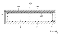
- the inner case positioning portion (for example, the rib 115) is not integrally molded with the inner case 105, but is formed as an outer. It may be integrally molded with the case 102.
- the inner case positioning portion may be composed of a separate annular member different from the outer case unlike the inner case, and the inner case positioning portion composed of the annular member may be formed on the outer peripheral surface of the inner case and the inner circumference of the outer case. It may be configured to be inserted between the faces.
- the inner case positioning portion is made of an elastic body, for example, a rubber material or a metal material having elasticity, because the assembling property can be improved.
- a plurality of batteries 7 are arranged in 2 rows and 2 columns in the inner case 5, but in the battery pack of the present disclosure, the plurality of batteries are used. , N rows and M columns (where N and M are both natural numbers, but at least one of N and M is an integer of 2 or more).
- the outer gas discharge hole 3 is covered with the mesh-shaped discharge hole covering member 4, but the outer gas discharge hole may not be covered with the mesh-shaped discharge hole covering member. ..
- the outer gas discharge part is composed of one outer gas discharge hole 3 and the inner gas discharge part is composed of one inner gas discharge hole 12, but the outer gas discharge part is composed of one inner gas discharge hole 12. It may be composed of two or more outer gas discharge holes, and the inner gas discharge portion may also be composed of two or more inner gas discharge holes.
- the secondary battery has a structure that is destroyed when the internal pressure exceeds a predetermined pressure, and the generated gas or the like is discharged to the outside.
- At least one of the inner gas discharge part and the outer gas discharge part may be a structure that is destroyed when the internal pressure becomes a predetermined pressure or more, and such a structure has strength (rigidity) as compared with other parts, for example. ) May be low.
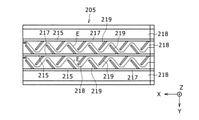
- FIG. 6 is a plan view corresponding to FIG. 4 in the inner case 205 included in the battery pack of the second embodiment.
- the gas guide passage 218 is located between two adjacent ribs 215 at a distance.
- at least one rib 215 has one ridge portion 217.
- a plurality of protrusions 219 that protrude from the ridges 217 and are spaced apart from each other so as to move away from the ridges 217 toward the downstream side of the gas flow.
- the gas can be flowed on the zigzag path shown by the arrow E in FIG. 6, and the path length until the gas is discharged to the outside can be lengthened. Therefore, the cooling effect of the gas can be further improved.
- the protrusion 219 protrudes from the ridge portion 217 so as to move away from the ridge portion 217 as it goes to the downstream side of the gas flow.
- the protrusion 219 protrudes from the ridge 217 toward the downstream side of the gas flow toward the tip from the root on the ridge 217 side. Therefore, the protrusion 219 does not obstruct the flow of the gas to the downstream side, and the gas can be smoothly flowed to the downstream side.
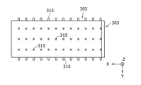
- FIG. 7 is a plan view corresponding to FIG. 4 in the inner case 305 included in the battery pack of the third embodiment.
- the plurality of inner case positioning portions include a plurality of columnar projecting portions 315 arranged at intervals from each other.
- the protrusion 315 may have, for example, a boss shape (cylindrical shape) or a prismatic shape.
- the gas can be agitated by the plurality of columnar protrusions 315, and turbulence can be caused. Therefore, the gas can be cooled more effectively.
- FIG. 8 is a cross-sectional view corresponding to FIG. 2 in the battery pack 401 of the fourth embodiment.
- the battery pack 401 differs from the battery pack 1 only in the two configurations described below. Specifically, the battery pack 401 has inner gas at one side end portion and the other side end portion in the height direction (corresponding to the X direction) of the cylindrical battery 7 in which the inner case 405 is fixed to the battery storage chamber 411. It differs from the battery pack 1 in that it has an inner gas discharge hole 477,478 as an example of the discharge unit. Further, the battery pack 401 is different from the battery pack 1 in that the outer case 402 has outer gas discharge holes 487,488 as an example of the outer gas discharge portion in the central portion located at a portion other than both ends in the X direction.
- the outer gas discharge hole 487 is provided at one end of the outer case 402 in the Z direction and communicates with all gas guide passages (not shown) located on one side in the Z direction. Further, the outer gas discharge hole 488 is provided at the other end of the outer case 402 in the Z direction and communicates with all the gas guide passages (not shown) located on the other side in the Z direction.
- the inner case positioning portion when the inner case positioning portion is composed of ribs and the plurality of protrusions 219 described with reference to FIG. 6 are formed on the ribs, the inner case positioning portion is located on one side in the X direction.
- the gas flow direction In the gas guide passage and the gas guide passage located on the other side in the X direction, the gas flow direction is opposite to the X direction. Therefore, the plurality of protrusions are formed so that the inclination direction (inclination direction) of the protrusions is different from each other on one side in the X direction and the other side in the X direction with the outer gas discharge holes 487,488 forming positions in the X direction as a boundary. Become.
- the inner case positioning portion may include both the plurality of ribs 15 described with reference to FIGS. 3 and 4 and the plurality of protrusions 315 described with reference to FIG. 7.
- the outer case 2 has a rectangular parallelepiped shape
- the outer case of the present disclosure does not have to have a rectangular parallelepiped shape, and may have any shape as long as it can have an inner case accommodating chamber and an outer gas discharge portion.
- the inner case of the present disclosure may have any shape as long as it can have a battery accommodating chamber and an inner gas discharging portion.
- the battery packs 1,101,401 have a substantially rectangular parallelepiped appearance, and the gas guide passage 18 extends in the X direction (longitudinal direction) or extends on a zigzag path along the X direction.
- the gas guide passage may extend in the width direction of the battery pack or may extend along a zigzag path along the width direction.
- the gas guide passage may include a portion extending along the longitudinal direction and a portion extending along the width direction of the battery pack.
- the gas guide passage may include a portion extending in a direction extending at an acute angle in the longitudinal direction of the battery pack, for example, the gas guide passage extends along the diagonal line of the battery pack in the XY plane. May be present.
- the battery case of the present disclosure may have a spiral rib. By providing such a spiral rib, the path length of the gas guide passage can be remarkably lengthened even in a compact battery case, and the gas cooling performance can be improved.
Abstract
Description
図1は、本開示の第1実施形態に係る電池パック1の斜視図である。また、図2は、図1のA-A線断面図(電池パック1を、そのY方向中央を通過するXZ平面で切断したときの断面図)である。また、図3は、図1のB-B線断面図(電池パック1におけるそのX方向の中央でも端部でもない箇所をYZ平面で切断したときの断面図)である。図1に示すように、電池パック1は、略直方体の形状を有するアウターケース2を備える。アウターケース2は、例えば、金属材料や樹脂材料で構成される。アウターケース2は、X方向の一方側端部に外側ガス排出部の一例としての1つの外側ガス排出孔3を有する。電池パック1は、更に、金属や樹脂等で構成されるメッシュ状(網目状)の排出孔被覆部材4を備える。排出孔被覆部材4は、固定手段、例えば、接着剤や溶着部によって外側ガス排出孔3を塞ぐようにアウターケース2に固定される。排出孔被覆部材4はメッシュ状でなくても良く、排出ガスを通過し、外部からの水などの液体を遮断する透気防水性素材、例えば、ゴアテックス(登録商標)等で構成しても良い。 (First Embodiment)
FIG. 1 is a perspective view of the
図6は、第2実施形態の電池パックが備えるインナーケース205における図4に対応する平面図である。第2実施形態では、第1実施形態との比較において、インナーケース205のリブ215の形状(構造)のみが異なり、第2実施形態のその他の全ての構成は、第1実施形態と一致する。図6に示すように、インナーケース205では、ガス案内通路218が、間隔をおいて隣り合う2つのリブ215の間に位置する。また、内側ガス排出孔12側(図2参照)から外側ガス排出孔3(図2参照)に向かう方向をガスの流れ方向とするとき、なくとも1つのリブ215が、1つの突条部217と、ガスの流れの下流側に行くにしたがって突条部217から離れるように突条部217から突出すると共に互いに間隔をおいて配置される複数の突起219と、を有する。 (Second Embodiment)
FIG. 6 is a plan view corresponding to FIG. 4 in the
図7は、第3実施形態の電池パックが備えるインナーケース305における図4に対応する平面図である。第3実施形態では、第1実施形態との比較において、インナーケース305のインナーケース位置決め部の形状(構造)のみが異なり、第3実施形態のその他の全ての構成は、第1実施形態と一致する。図7に示すように、第3実施形態では、複数のインナーケース位置決め部が、互いに間隔をおいて配置される複数の柱状の突出部315を含む。突出部315は、例えば、ボス形状(円柱形状)でもよく、角柱形状でもよい。 (Third Embodiment)
FIG. 7 is a plan view corresponding to FIG. 4 in the
図8は、第4実施形態の電池パック401における図2に対応する断面図である。電池パック401は、次に説明する2つの構成のみが、電池パック1と異なる。詳しくは、電池パック401は、インナーケース405が電池収容室411に固定されている円筒形の電池7の高さ方向(X方向に一致)の一方側端部と他方側端部とに内側ガス排出部の一例としての内側ガス排出孔477,478を有する点が、電池パック1と異なる。また、電池パック401は、アウターケース402がX方向において両端部以外に位置する中央部に外側ガス排出部の一例としての外側ガス排出孔487,488を有する点が、電池パック1と異なる。 (Fourth Embodiment)
FIG. 8 is a cross-sectional view corresponding to FIG. 2 in the
なお、本開示は、上記実施形態およびその変形例に限定されるものではなく、本願の特許請求の範囲に記載された事項およびその均等な範囲において種々の改良や変更が可能である。 (Other variants)
The present disclosure is not limited to the above-described embodiment and its modifications, and various improvements and changes can be made within the scope of the claims of the present application and the equivalent scope thereof.
Claims (9)
- 複数の電池を収容する電池収容室を有し、前記電池収容室に収納された前記電池で発生したガスを前記電池収容室外に排出させる内側ガス排出部を含むインナーケースと、
前記インナーケースを収容するインナーケース収容室を有し、前記ガスを外部に排出させる外側ガス排出部を含むアウターケースと、
前記インナーケースの外面から前記アウターケースの内面まで延びて前記インナーケースを前記アウターケースに対して位置決めすると共に、互いに間隔をおいて配置される複数のインナーケース位置決め部と、
前記インナーケースの外面、前記アウターケースの内面、及び前記複数のインナーケース位置決め部で画定されると共に、前記内側ガス排出部側から前記外側ガス排出部側へガスを案内する1以上のガス案内通路と、
を備える、電池ケース。 An inner case having a battery accommodating chamber for accommodating a plurality of batteries and including an inner gas discharging portion for discharging the gas generated by the batteries accommodated in the battery accommodating chamber to the outside of the battery accommodating chamber.
An outer case having an inner case accommodating chamber for accommodating the inner case and including an outer gas discharging portion for discharging the gas to the outside.
A plurality of inner case positioning portions extending from the outer surface of the inner case to the inner surface of the outer case to position the inner case with respect to the outer case and arranged at intervals from each other.
One or more gas guide passages defined by the outer surface of the inner case, the inner surface of the outer case, and the plurality of inner case positioning portions, and guide gas from the inner gas discharge portion side to the outer gas discharge portion side. When,
A battery case. - 前記複数のインナーケース位置決め部が、複数のリブを含む、請求項1に記載の電池ケース。 The battery case according to claim 1, wherein the plurality of inner case positioning portions include a plurality of ribs.
- 前記ガス案内通路が、間隔をおいて隣り合う2つの前記リブの間に位置し、
前記内側ガス排出部から前記外側ガス排出部に向かう方向をガスの流れ方向とするとき、少なくとも1つの前記リブが、1つの突条部と、前記ガスの流れの下流側に行くにしたがって前記突条部から離れるように前記突条部から突出すると共に互いに間隔をおいて位置する複数の突起とを有する、請求項2に記載の電池ケース。 The gas guide passage is located between two adjacent ribs at a distance.
When the direction from the inner gas discharge portion to the outer gas discharge portion is the gas flow direction, the protrusions as at least one of the ribs goes to one protrusion and the downstream side of the gas flow. The battery case according to claim 2, further comprising a plurality of protrusions protruding from the protrusions so as to be separated from the strips and located at intervals from each other. - 前記複数のインナーケース位置決め部が、互いに間隔をおいて配置される複数の柱状の突出部を含む、請求項1から3のいずれか1つに記載の電池ケース。 The battery case according to any one of claims 1 to 3, wherein the plurality of inner case positioning portions include a plurality of columnar projecting portions arranged at intervals from each other.
- 前記電池収容室は、複数の円筒形電池を収容するようになっており、
前記アウターケースが、前記電池収容室に収容されている前記円筒形電池の高さ方向の一方側端部のみに前記外側ガス排出部を有する一方、前記インナーケースが前記高さ方向の他方側端部のみに前記内側ガス排出部を有する、請求項1から4のいずれか1つに記載の電池ケース。 The battery accommodating chamber is adapted to accommodate a plurality of cylindrical batteries.
The outer case has the outer gas discharge portion only on one side end in the height direction of the cylindrical battery housed in the battery storage chamber, while the inner case has the other side end in the height direction. The battery case according to any one of claims 1 to 4, wherein the battery case has the inner gas discharging portion only in the portion. - 前記電池収容室は、複数の円筒形電池を収容するようになっており、
前記インナーケースが、前記電池収容室に収容されている前記円筒形電池の高さ方向の一方側端部と他方側端部とに前記内側ガス排出部を有する一方、前記アウターケースが前記高さ方向において両端部以外に位置する中央部に前記外側ガス排出部を有する、請求項1から4のいずれか1つに記載の電池ケース。 The battery accommodating chamber is adapted to accommodate a plurality of cylindrical batteries.
The inner case has the inner gas discharge portion at one side end portion and the other side end portion in the height direction of the cylindrical battery housed in the battery storage chamber, while the outer case has the height. The battery case according to any one of claims 1 to 4, which has the outer gas discharging portion in a central portion located at a central portion other than both ends in the direction. - 前記インナーケース及び前記複数のインナーケース位置決め部が、絶縁性を有する絶縁材料で一体に構成される、請求項1から6のいずれか1つに記載の電池ケース。 The battery case according to any one of claims 1 to 6, wherein the inner case and the plurality of inner case positioning portions are integrally formed of an insulating material having an insulating property.
- 前記外側ガス排出部を覆うメッシュ状の部材を備えるか、又は前記ガスを通過させる一方、外部の水が前記アウターケース内に浸入することを防止できる透気防水性素材で構成されると共に、前記外側ガス排出部を覆う透気防水性部材を備える、請求項1から7のいずれか1つに記載の電池ケース。 It is provided with a mesh-like member that covers the outer gas discharge portion, or is made of an air-permeable and waterproof material that allows the gas to pass through and prevents external water from entering the outer case, and is described as described above. The battery case according to any one of claims 1 to 7, further comprising an air-permeable waterproof member that covers the outer gas discharge portion.
- 請求項1から8のいずれか1つに記載の電池ケースと、
前記電池ケースの前記電池収容室に配置された前記複数の電池と、
を備える、電池パック。 The battery case according to any one of claims 1 to 8.
The plurality of batteries arranged in the battery accommodating chamber of the battery case, and
Equipped with a battery pack.
Priority Applications (4)
| Application Number | Priority Date | Filing Date | Title |
|---|---|---|---|
| CN202180058796.4A CN116057761A (en) | 2020-07-31 | 2021-07-09 | Battery case and battery pack |
| JP2022540126A JPWO2022024713A1 (en) | 2020-07-31 | 2021-07-09 | |
| US18/006,573 US20230275317A1 (en) | 2020-07-31 | 2021-07-09 | Battery case, and battery pack |
| EP21849542.2A EP4191766A1 (en) | 2020-07-31 | 2021-07-09 | Battery case, and battery pack |
Applications Claiming Priority (2)
| Application Number | Priority Date | Filing Date | Title |
|---|---|---|---|
| JP2020-130314 | 2020-07-31 | ||
| JP2020130314 | 2020-07-31 |
Publications (1)
| Publication Number | Publication Date |
|---|---|
| WO2022024713A1 true WO2022024713A1 (en) | 2022-02-03 |
Family
ID=80037294
Family Applications (1)
| Application Number | Title | Priority Date | Filing Date |
|---|---|---|---|
| PCT/JP2021/025881 WO2022024713A1 (en) | 2020-07-31 | 2021-07-09 | Battery case, and battery pack |
Country Status (5)
| Country | Link |
|---|---|
| US (1) | US20230275317A1 (en) |
| EP (1) | EP4191766A1 (en) |
| JP (1) | JPWO2022024713A1 (en) |
| CN (1) | CN116057761A (en) |
| WO (1) | WO2022024713A1 (en) |
Cited By (1)
| Publication number | Priority date | Publication date | Assignee | Title |
|---|---|---|---|---|
| WO2022244853A1 (en) * | 2021-05-19 | 2022-11-24 | 大日本印刷株式会社 | Water-impermeable degassing film for power storage device |
Citations (5)
| Publication number | Priority date | Publication date | Assignee | Title |
|---|---|---|---|---|
| JP5378670B2 (en) | 2006-10-13 | 2013-12-25 | パナソニック株式会社 | Battery pack |
| WO2018025559A1 (en) * | 2016-08-02 | 2018-02-08 | パナソニックIpマネジメント株式会社 | Battery cover and battery pack |
| WO2018123573A1 (en) * | 2016-12-27 | 2018-07-05 | パナソニックIpマネジメント株式会社 | Battery module |
| WO2020153018A1 (en) * | 2019-01-25 | 2020-07-30 | 三洋電機株式会社 | Battery pack |
| WO2020153017A1 (en) * | 2019-01-25 | 2020-07-30 | 三洋電機株式会社 | Battery pack |
-
2021
- 2021-07-09 US US18/006,573 patent/US20230275317A1/en active Pending
- 2021-07-09 WO PCT/JP2021/025881 patent/WO2022024713A1/en active Application Filing
- 2021-07-09 CN CN202180058796.4A patent/CN116057761A/en active Pending
- 2021-07-09 EP EP21849542.2A patent/EP4191766A1/en active Pending
- 2021-07-09 JP JP2022540126A patent/JPWO2022024713A1/ja active Pending
Patent Citations (5)
| Publication number | Priority date | Publication date | Assignee | Title |
|---|---|---|---|---|
| JP5378670B2 (en) | 2006-10-13 | 2013-12-25 | パナソニック株式会社 | Battery pack |
| WO2018025559A1 (en) * | 2016-08-02 | 2018-02-08 | パナソニックIpマネジメント株式会社 | Battery cover and battery pack |
| WO2018123573A1 (en) * | 2016-12-27 | 2018-07-05 | パナソニックIpマネジメント株式会社 | Battery module |
| WO2020153018A1 (en) * | 2019-01-25 | 2020-07-30 | 三洋電機株式会社 | Battery pack |
| WO2020153017A1 (en) * | 2019-01-25 | 2020-07-30 | 三洋電機株式会社 | Battery pack |
Cited By (1)
| Publication number | Priority date | Publication date | Assignee | Title |
|---|---|---|---|---|
| WO2022244853A1 (en) * | 2021-05-19 | 2022-11-24 | 大日本印刷株式会社 | Water-impermeable degassing film for power storage device |
Also Published As
| Publication number | Publication date |
|---|---|
| CN116057761A (en) | 2023-05-02 |
| JPWO2022024713A1 (en) | 2022-02-03 |
| US20230275317A1 (en) | 2023-08-31 |
| EP4191766A1 (en) | 2023-06-07 |
Similar Documents
| Publication | Publication Date | Title |
|---|---|---|
| JP7401467B2 (en) | pack batteries | |
| US10511002B2 (en) | Battery module | |
| JP6256846B2 (en) | Battery module | |
| WO2020153016A1 (en) | Battery pack | |
| JPWO2017130259A1 (en) | Battery pack | |
| EP3916876B1 (en) | Battery pack | |
| US20220085453A1 (en) | Battery pack | |
| JP2008166191A (en) | Battery pack | |
| JPWO2007039999A1 (en) | Battery pack | |
| JP2009110833A (en) | Battery pack and separator for battery pack | |
| WO2020153018A1 (en) | Battery pack | |
| WO2022024713A1 (en) | Battery case, and battery pack | |
| JP6769176B2 (en) | Battery module | |
| CN115588805A (en) | Lower plastic of battery, top cap subassembly and battery of battery | |
| WO2022024894A1 (en) | Battery pack and battery case | |
| US11984613B2 (en) | Battery pack | |
| JP2010073957A (en) | Capacitor unit | |
| US20220367970A1 (en) | Battery pack | |
| WO2023162841A1 (en) | Battery holder and battery pack | |
| JP2023534855A (en) | Battery module and battery pack containing same | |
| JP2023124435A (en) | battery pack | |
| JP2023124436A (en) | battery pack |
Legal Events
| Date | Code | Title | Description |
|---|---|---|---|
| 121 | Ep: the epo has been informed by wipo that ep was designated in this application |
Ref document number: 21849542 Country of ref document: EP Kind code of ref document: A1 |
|
| ENP | Entry into the national phase |
Ref document number: 2022540126 Country of ref document: JP Kind code of ref document: A |
|
| WWE | Wipo information: entry into national phase |
Ref document number: 2021849542 Country of ref document: EP |
|
| ENP | Entry into the national phase |
Ref document number: 2021849542 Country of ref document: EP Effective date: 20230228 |
|
| NENP | Non-entry into the national phase |
Ref country code: DE |