WO2022024331A1 - 入出力スイッチ及び通信システム - Google Patents
入出力スイッチ及び通信システム Download PDFInfo
- Publication number
- WO2022024331A1 WO2022024331A1 PCT/JP2020/029390 JP2020029390W WO2022024331A1 WO 2022024331 A1 WO2022024331 A1 WO 2022024331A1 JP 2020029390 W JP2020029390 W JP 2020029390W WO 2022024331 A1 WO2022024331 A1 WO 2022024331A1
- Authority
- WO
- WIPO (PCT)
- Prior art keywords
- switch
- port
- input
- switches
- output
- Prior art date
- Legal status (The legal status is an assumption and is not a legal conclusion. Google has not performed a legal analysis and makes no representation as to the accuracy of the status listed.)
- Ceased
Links
Images







Classifications
-
- H—ELECTRICITY
- H04—ELECTRIC COMMUNICATION TECHNIQUE
- H04L—TRANSMISSION OF DIGITAL INFORMATION, e.g. TELEGRAPHIC COMMUNICATION
- H04L12/00—Data switching networks
- H04L12/02—Details
- H04L12/12—Arrangements for remote connection or disconnection of substations or of equipment thereof
-
- H—ELECTRICITY
- H04—ELECTRIC COMMUNICATION TECHNIQUE
- H04L—TRANSMISSION OF DIGITAL INFORMATION, e.g. TELEGRAPHIC COMMUNICATION
- H04L49/00—Packet switching elements
- H04L49/15—Interconnection of switching modules
-
- H—ELECTRICITY
- H04—ELECTRIC COMMUNICATION TECHNIQUE
- H04L—TRANSMISSION OF DIGITAL INFORMATION, e.g. TELEGRAPHIC COMMUNICATION
- H04L49/00—Packet switching elements
- H04L49/15—Interconnection of switching modules
- H04L49/1515—Non-blocking multistage, e.g. Clos
-
- H—ELECTRICITY
- H04—ELECTRIC COMMUNICATION TECHNIQUE
- H04L—TRANSMISSION OF DIGITAL INFORMATION, e.g. TELEGRAPHIC COMMUNICATION
- H04L49/00—Packet switching elements
- H04L49/25—Routing or path finding in a switch fabric
- H04L49/253—Routing or path finding in a switch fabric using establishment or release of connections between ports
-
- H—ELECTRICITY
- H04—ELECTRIC COMMUNICATION TECHNIQUE
- H04L—TRANSMISSION OF DIGITAL INFORMATION, e.g. TELEGRAPHIC COMMUNICATION
- H04L49/00—Packet switching elements
- H04L49/70—Virtual switches
Definitions
- the present invention relates to the technology of an input / output switch and a communication system.
- Non-blocking networks are applied in various fields such as telephone networks, ATM (Asynchronous Transfer Mode) networks, wavelength division multiplexing optical networks, and time division packet switching.
- Clos networks are a practical method for constructing non-blocking networks.
- the Clos network basically consists of three stages: an input stage, an intermediate stage, and an output stage.
- a folded Clos network is a collection of an input stage and an output stage in the same input / output switch.
- one side of the input / output switch is usually connected to the line on the subscriber device (endpoint) side, and the other side is connected to the line on the intermediate switch side.
- the input / output switches in the folded Clos network are symmetrically arranged, a surplus is generated in the input / output ports on the subscriber device side, and the port utilization efficiency deteriorates.
- Non-Patent Document 1 discloses a technique for improving port utilization efficiency by dividing an input / output switch into two virtual switches when configuring a folded Clos network. ..
- Non-Patent Document 1 the port utilization efficiency is improved by dividing the input / output switch into two virtual switches. However, further improvement in port utilization efficiency is desired.
- an object of the present invention is to provide a technique capable of improving port utilization efficiency in a folded Clos network that performs non-blocking forwarding.
- One aspect of the present invention is a plurality of virtual switches formed by asymmetrically dividing a switch in which ports are symmetrically arranged, and a port on the endpoint side and a port on the intermediate switch side assigned to each virtual switch. And, a part of the port on the endpoint side of the virtual switch is an input / output switch that functions as a port forming a path for returning traffic between the virtual switches.
- One aspect of the present invention is a plurality of virtual switches formed by asymmetrically dividing a switch in which ports are symmetrically arranged, and a port on the endpoint side and a port on the intermediate switch side assigned to each virtual switch. And, a part of the port on the endpoint side and the port on the intermediate switch side of the virtual switch is an input / output switch that functions as a port forming a path directly connected to the relay network.
- One aspect of the present invention is a plurality of virtual switches formed by asymmetrically dividing a switch in which ports are symmetrically arranged, and a port on the endpoint side and a port on the intermediate switch side assigned to each virtual switch. And, a part of the port on the endpoint side of the virtual switch functions as a port forming a path for returning traffic between the virtual switches, and the port on the endpoint side of the virtual switch and the intermediate.
- Some of the ports on the switch side are input / output switches that function as ports that form a path directly connected to the relay network.
- One aspect of the present invention is a communication system having a folded Clos network equipped with the above-mentioned input / output switch.
- the communication system according to the embodiment of the present invention constitutes a folded Clos network that performs non-blocking transfer.
- the folded Clos network is composed of an input / output switch (IOSW) and an intermediate switch.
- IOSW input / output switch
- IOSW input / output switch
- FIG. 1 is the most basic input / output switch when configuring a folded Clos network.
- this configuration is referred to as a switch configuration A.
- the input / output switch 11 is, for example, a grid type N ⁇ M matrix switch, a triangular grid type, a planar type, and may be a torus type or a banyan net. In the case of an optical switch, it may be a space division type, a time division, a wavelength division, or a free space type.
- one side surface 12a of the input / output switch 11 is a port on the endpoint side, and the other side surface 12b is a port on the intermediate switch side.
- the number of ports M of the input / output switch 11 is as follows. M ⁇ q ⁇ 2 (p-1)... (12) Generally, when the number of intermediate switches is L, 2 [(p-1) / q] + 1 ⁇ L, and [] is a Gaussian symbol.
- the number of lines q on the intermediate switch side is larger than the number of lines p on the endpoint side. Therefore, as shown in FIG. 1, when the line from the port on the endpoint side is connected to one side surface 12a of the input / output switch 11 and the line from the intermediate switch side is connected to the other side surface 12b, the line from the intermediate switch side is connected to the one side surface 12a. There is a surplus on the port on the endpoint side.
- FIG. 2 shows an input / output switch in the case of configuring a folded Clos network, in which the input / output switch in which the ports are symmetrically arranged is divided into two asymmetric virtual switches to improve the port utilization efficiency. Is.
- this configuration is referred to as a switch configuration B.
- the input / output switch 21 is virtually divided into two virtual switches 23a and 23b for use.
- the ports on one side surface 22a and the other side surface 22b of the input / output switch 21 are assigned to the port on the endpoint side and the port on the intermediate switch side so as to satisfy the constraint condition for non-blocking forwarding. Be done.
- the switch configuration B satisfies the constraint condition that the input / output switch 21 is virtually divided into two virtual switches 23a and 23b, and the ports on one side surface 22a and the other side surface 22b are transferred without blocking.
- FIG. 3 shows that the switch configuration B is further assigned a return port for folding back between virtual switches.
- This configuration is a further improvement of the switch configuration B and is the basic configuration of the present invention.
- this configuration is referred to as a switch configuration C.
- the input / output switch 31 is virtually divided into two asymmetric virtual switches 33a and 33b for use.
- This configuration is the same as the switch configuration B shown in FIG.
- a folding port for forming a path for folding back between the two virtual switches 33a and 33b without going through the intermediate switch is provided.
- the return ports are provided on the endpoint side ports by the number of ports corresponding to the traffic returning between the divided virtual switches 33a and 33b. That is, a part of the port on the endpoint side functions as the above-mentioned return port.
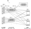
- FIG. 4 is an explanatory diagram of an outline of the communication system 100 according to the first embodiment of the present invention.
- the communication system 100 includes input / output switches 101-1, 101-2, ..., Intermediate switches 102-1, 102-2, ..., And subscriber devices 103-1, 103. It is composed of -2, ..., And realizes a folded Clos network. Subscriber devices 103-1, 103-2, ... Are endpoints, for example, ONUs (Optical Network Units).
- the communication system 100 is an optical network, but the communication system 100 is not limited thereto.
- As the above-mentioned switch configuration C are used. That is, as shown in FIG. 3, in the input / output switch of the switch configuration C, one switch is divided into two virtual switches, and a return port is further provided. This return port forms a path for returning traffic between virtual switches from the subscriber devices 103-1, 103-2, ... Side to the subscriber devices 103-1, 103-2, ... Side.
- the switch configuration A shown in FIG. 1 is used as the input / output switch and the number of ports of the input / output switch is M, the constraint conditions for performing non-blocking transfer are as follows. q ⁇ 2 (p-1) M ⁇ q ⁇ 2 (p-1)
- the input / output switches 101-1, 101-2, ... are used with the switch configuration C shown in FIG.
- the port utilization efficiency at the time of the equal sign is as follows. 2 (p + k) / (3p-2 + k) ... (43)
- a port directly connected to the relay network from the intermediate layer SW may be provided. This port is provided separately from the port connected to IOSW. The port directly connected to the relay network is connected to the port connected to the IOSW facing the intermediate layer SW.
- one of the subscriber devices in the route of the subscriber device-IOSW-intermediate layer SW-IOSW-subscriber device is connected to the relay network.
- the ports connected to one or more IOSWs may be diverted.
- the opposite ports of the intermediate layer SW are diverted in groups, in the case of asymmetry, there is a half route in the design of the IOSW route. It is desirable to configure the system so as to satisfy the constraint condition by adding, and in this case, non-blocking can be maintained by the same constraint expression as before the diversion. This also applies to the following examples.
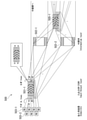
- FIG. 5 is an explanatory diagram of an outline of the communication system 200 according to the second embodiment of the present invention.
- the communication system 200 according to the second embodiment of the present invention includes input / output switches 211-1, 201-2, ..., Intermediate switches 202-1, 202-2, ..., And a subscriber device 203. It is composed of -1, 203-2, ..., And realizes a folded Clos network. Subscriber devices 203-1, 203-2, ... Are endpoints, eg ONUs.
- the input / output switches 211-1, 201-2, ... are each divided into two virtual switches. Further, the input / output switches 211-1, 201-2, ... Are connected to the relay network from the subscriber devices 203-1, 203-2, ... Without going through the intermediate switches 202-1, 202-2, .... Equipped with a relay network port that is directly connected. The same number of relay network ports are provided on the subscriber device side and the intermediate switch side of the input / output switches 211-1, 201-2, ....
- the set of the port on the subscriber device side and the port on the intermediate switch side of one of the virtual switches is provided only in parallel with the set of the relay network port on the subscriber device side and the relay network port on the intermediate switch side.
- the reason for this is that there is no distinction between the subscriber-side port provided in the first embodiment for connecting to the subscriber device and the subscriber-side relay network port connected to the subscriber device, and the configuration is such that they can be connected arbitrarily. This is because it is easy to manage.
- the port on the intermediate switch side provided in the first embodiment connected to the intermediate switch and the relay network port on the intermediate switch side connected to the relay network and it is managed to connect arbitrarily. This is because it is easy.
- the port utilization efficiency at the time of the equal sign in this embodiment is as follows. (2p + h) / (3p-2 + h) ... (51)
- the relay network port directly connected to the relay network from the subscriber devices 203-1, 203-2, ... by providing the relay network port directly connected to the relay network from the subscriber devices 203-1, 203-2, ..., The use of the port for the intermediate switch, which is about twice as large as the port on the subscriber side, is reduced. Therefore, the utilization efficiency can be improved. As shown in the figure, a port directly connected to the relay network from the intermediate switch 202 may be provided.
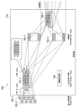
- FIG. 6 is an explanatory diagram of an outline of the communication system 300 according to the third embodiment of the present invention.
- the communication system 300 according to the third embodiment of the present invention includes input / output switches 301-1, 301-2, ..., Intermediate switches 302-1, 302-2, ..., And subscriber devices 303-1, 303. It is composed of -2, ..., And realizes a folded Clos network. Subscriber devices 303-1, 303-2, ... Are endpoints, eg ONUs.
- One switch is divided into two virtual switches, and the switch is folded back between the virtual switches.
- a port is provided, and a relay network port that directly connects the subscriber device to the relay network is added.
- a port directly connected to the relay network from the intermediate switch 302 may be provided.
- the port utilization efficiency at the time of equal sign is as follows. (2 (p + k) + h) / (3p-2 + k + h) ... (61)
- the port utilization efficiency of the present embodiment is better than that of the case where the switch configuration B shown in FIG. 2 is used.
- FIG. 7 is an explanatory diagram showing an outline of the communication system 400 according to the fourth embodiment of the present invention.
- the communication system 400 according to the fourth embodiment of the present invention includes input / output switches 401-1, ..., Intermediate switches 402-1, 402-2, ..., And subscriber devices 403-1, 4032, ... And the folding switch 405-1, ..., And realize a folded Clos network.
- Subscriber devices 403-1, 4032, ... Are endpoints, eg ONUs.
- the input / output switches 401-1 and ... the one using the switch configuration C shown in FIG. 3 is used as in the first embodiment described above. Be done. That is, the input / output switches 401-1, ... Are divided into two virtual switches, and are further provided with a return port for folding back between the two virtual switches. Further, in the present embodiment, the return switch 405-1, ... Which forms a path for returning a part of the traffic of the input / output switches 401-1 to the relay network side is provided.
- This embodiment has a configuration in which a part of the input / output switches of the first embodiment is folded back to the relay network side.
- the number of return switches 405-1, ... Depends on the ratio of the connection line to the relay network.
- the return is for each input / output switch, but it may be for each subscriber port.
- a port directly connected to the relay network from the intermediate switch 402 may be provided.
- FIG. 8 is an explanatory diagram showing an outline of the communication system 500 according to the fifth embodiment of the present invention.
- Subscriber devices 503-1, 503-2, ... Are endpoints, eg ONUs.
- the same input / output switches 501-1 and the same as those of the second embodiment shown in FIG. 5 are used. Further, in the present embodiment, a folding switch 505, ..., which forms a path for folding a part of the input / output switches 501-1, ... To the relay network side, is provided.
- This embodiment has a configuration in which a part of the input / output switches of the second embodiment is folded back to the relay network side.
- the number of return switches 505-1, ... Depends on the connection line ratio to the relay network.
- the return is for each input / output switch, but it may be for each subscriber port.
- the use of the port for the intermediate switch which is about twice the subscriber port, can be reduced, so that the utilization efficiency is improved.
- a port directly connected to the relay network from the intermediate switch 502 may be provided.
- FIG. 9 is an explanatory diagram showing an outline of the communication system 600 according to the sixth embodiment of the present invention.
- the communication system 600 according to the sixth embodiment of the present invention includes input / output switches 601-1, ..., Intermediate switches 602-1, 602-2, ..., And subscriber devices 603-1, 6032, ... And the folding switch 605-1, ..., And realize a folded Clos network.
- Subscriber devices 603-1, 6032, ... Are endpoints, eg ONUs.
- the configuration of the folding switch 605-1, ... Is the same as that of the fourth embodiment and the fifth embodiment described above.
- This embodiment has a configuration in which a part of the input / output switches of the third embodiment is folded back to the relay network side.
- the number of return switches 605-1, ... Depends on the connection line ratio to the relay network. The return is for each input / output switch, but it may be for each subscriber port.
- a port directly connected to the relay network from the subscriber device by providing a port directly connected to the relay network from the subscriber device, the use of the port to the intermediate switch, which is about twice the subscriber port, can be reduced, so that the utilization efficiency is improved.
- a port directly connected to the relay network from the intermediate switch 702 may be provided.
- FIG. 10 is an explanatory diagram of an outline of the communication system 700 according to the seventh embodiment of the present invention.
- the communication system 700 according to the seventh embodiment of the present invention includes input / output switches 701-1, ..., Intermediate switches 702-1, 702-2, ..., And subscriber devices 703-1, 703-2, ... , A turnaround switch 705-1, ..., And a route setting unit 706, to realize a folded Clos network.
- the route setting unit 706 sets the route of each switch (input / output switch 701, intermediate switch 702 or return switch 705). Specifically, it is as follows.
- the route setting unit 706 sets the route for the input / output switch 701 so as to connect the subscriber device 703, the subscriber device 703, the port of the relay network, and the intermediate switch 702.
- the route setting unit 706 sets the route so as to connect the input / output switch 701 to the input / output switch 701 and the port of the relay network.
- the route setting unit 706 communicates between the subscriber devices 703 accommodated in the desired input / output switch 701 or the virtual SW, and communicates between the subscriber device 703 and the opposite device via the relay network. Is set so that can be realized.
- the route may be set by designating the entire route, by designating the opposite device or network, or according to the corresponding information provided in the station device 710 or other devices. It may be done so as to be a connection.
- connection instruction may be received from another management device, another system, or the like, or may be received from the subscriber device 703.
- it may be received in the communication performed at the time of initial connection or setting change, or the instruction may be included in a part of the signal exchanged in the communication.
- the contained instruction the source or destination address in the Ethernet frame or IP packet may be used.
- the instructions from the subscriber device set the route so that the instructions reach the route setting function at the time of initial connection or change, and then interact with the route setting function and wavelength setting function to determine the desired route, communication destination, etc.
- the wavelength, etc. is set for the subscriber device according to the acquired information
- the wavelength, etc. is set for the subscriber device
- the wavelength, etc. of the device or function included in the path is set.
- the wavelength and the like are set for them
- the route setting function sets the route so as to be a route according to information such as a desired route and a communication destination.
- Requests and instructions from subscriber equipment are transmitted to the switch, device, its control unit, its control system, or their control system via the input / output switch, intermediate switch, port for the relay network, or its dedicated port. May receive, or may be acquired by providing a monitor that acquires the signal somewhere on the port or switch. The monitor may be terminated by branching a part of the path and performing photoelectric conversion, or by using a semiconductor optical amplifier (SOA), a hypersaturation absorber, or the like, the conduction of the optical signal may be gain fluctuation or an element. It may be acquired as a fluctuation of the applied voltage or the applied current of.
- SOA semiconductor optical amplifier
- instructions such as wavelength setting to the subscriber may be given by normal communication via a function of transmitting a signal. If it is already communicating with the monitor or any of the grounds, the controlling function is the path that connects the signal light to the subscriber device via the junction branch or duplexer. It may be inserted in, or the signal light communicating with either ground is instructed by gain fluctuation such as SOA or hypersaturation absorption pair, fluctuation of the applied voltage or current of the element, or modulation by a modulator. May be good.
- the control unit sets a route so that the request or instruction reaches the setting unit, and when the setting unit receives the request or instruction by the monitor, the route can be monitored. Set. Then, the setting unit receives or monitors the request or instruction, and sets the route through which the subscriber device can communicate with the communication destination according to the request or instruction.
- the control unit sets a route so that the request or instruction reaches the setting unit, and when the control unit sends or receives the request or instruction by the monitor, the monitor and the instruction are inserted or modulated. Set to follow the possible route. Then, the control unit receives or monitors the request, instruction, reception confirmation, etc. from the subscriber device, the control device transmits the wavelength setting, etc. to the subscriber device, and when the transmission / reception with the subscriber device is completed, the control is performed. Set the route through which the subscriber device can communicate with the communication destination according to the request or instruction of the device. The wavelength setting, etc.
- the wavelength used by the subscriber device refers to the wavelength used by the subscriber device, transmission speed, modulation method, code, MAC, user data (analog / digital, continuous signal / frame, frame form (Ethernet (registered trademark) / OTN, etc.), etc.) Control method (MPLS, etc.), subscriber device and opposite device addresses (MAC address, IP address, VLAN tag, VXLAN tag), polarization used for polarization multiplexing, mode used for mode division multiplexing, core when using multi-core fiber Numbers, transmission lines when using multiple transmission lines, redundant configurations, setting of vendor-specific areas in OAM, etc.
- the monitor function acquires a request for setting or changing the route, wavelength, etc., and transfers the request to the route setting unit 706 or the wavelength setting function. If it is a request for setting or changing a route, the route setting unit 706 changes the route in response to the request. If the request is for a wavelength change, the wavelength can be changed without changing the path, and the change does not affect other devices, the wavelength setting function changes the wavelength. do. On the other hand, when the change affects other devices, the station device 710 stops the signal transfer or changes to a path that does not affect other devices, and then changes the wavelength or the like. Return the route after completion. If the change instruction or the like cannot be performed without communicating with the route setting unit 706, the route is changed so as to communicate with the route setting function as in the initial connection, and then the route is returned.
- the seventh embodiment of the present invention realizes the communication system according to the fourth embodiment shown in FIG. 7 as a station device 710.
- the port connection on the subscriber device side of the input / output switches 701-1, ... May be a single subscriber device, a star-type Passibe Double Star (PDS), a bus-type, or a ring-type Add Drop Multiplexer. It may be on the Drop side of the (ADM), it may be a part of the subscriber ring with a single station device, or it may be connected to the subscriber ring once with multiple station devices, and the station device or relay may be used. It may be a ring via a net.
- the station device 710 may be configured as, for example, an optical gateway.
- the station device itself may be connected to a ring or a mesh to become a larger virtual station device, or the station device or the virtual station device may be a ground station device and a mesh (3 ground if 4 ground).
- Optical folding may be performed at the port on the intermediate switch side of the input / output switches 701-1, ..., Input / output to the port may be branched by a splitter such as power / WDM (Wavelength Division Multiplexing), or You may use the same switch as a sash.
- a splitter such as power / WDM (Wavelength Division Multiplexing), or You may use the same switch as a sash.
- An OE / EO (light / electric) conversion device may be used in the middle of the crossing.
- optical node By connecting the nodes in the optical full-mesh network and the access surface and the local full-mesh surface, electrical processing such as packet conversion and multiplex / switch control can be minimized and relayed, and the optical path for each service is end-to-end. It may be an optical node called a photonic gateway (Photonic GW, PhGW) provided by.
- Photonic GW Photonic GW, PhGW
- wavelength management control may be provided, and as a method of wavelength control instruction, a management control signal is superimposed as an AMCC (Auxiliary Management and Control Channel) in a low frequency band that does not interfere with the user signal to have the same wavelength. It may be notified by, or it may be notified by a frame whose payload is user data.
- the switching control may be performed before the I / O switch is connected / at the same subscription port, at the Tap / input / output switch intermediate port / input / output switch intermediate port, and on the Tap / intermediate switch / station device external / relay network side.
- the switching may be performed in units of directions, or may be performed by combining the directions with wavelengths, frequencies, codes, and the like.
- a port directly connected to the relay network from the intermediate switch 702 may be provided.
- FIG. 11 is an explanatory diagram of an outline of the communication system 800 according to the eighth embodiment of the present invention.
- the communication system 800 according to the eighth embodiment of the present invention includes input / output switches 801-1, ..., Intermediate switches 802-1, 802-2, ..., And subscriber devices 803-1, 803-2, ... , A turnaround switch 805-1, ..., And a route setting unit 806, to realize a folded Clos network.
- the eighth embodiment of the present invention realizes the communication system according to the fourth embodiment of the present invention as a station device 810.
- the station device 810 may be configured as, for example, an optical gateway.
- the route setting unit 806 is configured in the same manner as the route setting unit 706. As shown in the figure, a port directly connected to the relay network from the intermediate switch 802 may be provided.
- FIG. 12 is an explanatory diagram of an outline of the communication system 900 according to the ninth embodiment of the present invention.
- the communication system 900 according to the ninth embodiment of the present invention includes input / output switches 901-1, ..., Intermediate switches 902-1, 902-2, ..., Subscriber devices 903-1, 9032, ... , A turnaround switch 905-1, ..., And a route setting unit 906, to realize a folded Clos network.
- a ninth embodiment of the present invention realizes the communication system according to the fifth embodiment of the present invention as a station device 910.
- the station device 910 may be configured as, for example, an optical gateway.
- the route setting unit 906 is configured in the same manner as the route setting unit 706. As shown in the figure, a port directly connected to the relay network from the intermediate switch 902 may be provided.
- FIG. 13 is an explanatory diagram of an outline of the communication system 1000 according to the tenth embodiment of the present invention.
- the communication system 1000 according to the tenth embodiment of the present invention includes input / output switches 1001-1, ..., Intermediate switches 1002-1, 1002-2, ..., Subscriber devices 1003-1, 1003-2, ... And the route setting unit 1006, a folded Clos network is realized.
- the tenth embodiment of the present invention realizes the communication system according to the first embodiment of the present invention as a station device 1010.
- the station device 1010 may be configured as, for example, an optical gateway.
- the route setting unit 1006 is configured in the same manner as the route setting unit 706. As shown in the figure, a port directly connected to the relay network from the intermediate switch 1002 may be provided.
- FIG. 14 is an explanatory diagram of an outline of the communication system 1100 according to the eleventh embodiment of the present invention.
- the communication system 1000 according to the eleventh embodiment of the present invention includes input / output switches 1101-1, ..., Intermediate switches 1102-1, 1102-2, ..., Subscriber devices 1103-1, 1103-2, ... And the route setting unit 1106, a folded Clos network is realized.
- the eleventh embodiment of the present invention realizes the communication system according to the second embodiment of the present invention as a station device 1110.
- the station device 1110 may be configured as, for example, an optical gateway.
- the route setting unit 1106 is configured in the same manner as the route setting unit 706. As shown in the figure, a port directly connected to the relay network from the intermediate switch 1102 may be provided.
- FIG. 15 is an explanatory diagram of an outline of the communication system 1200 according to the twelfth embodiment of the present invention.
- the communication system 1200 according to the twelfth embodiment of the present invention includes input / output switches 1201-1, ..., Intermediate switches 1202-1, 1202-2, ..., Subscriber devices 1203-1, 1203-2, ... And a route setting unit 1206, and a folded Clos network is realized.
- the twelfth embodiment of the present invention realizes the communication system according to the third embodiment of the present invention as the station device 1210.
- the station device 1210 may be configured as, for example, an optical gateway.
- the route setting unit 1206 is configured in the same manner as the route setting unit 706. As shown in the figure, a port directly connected to the relay network from the intermediate switch 1202 may be provided.
- Each switch described above may be configured by using a processor such as a CPU (Central Processing Unit) and a memory. In this case, each switch described above operates by the processor executing the program. All or part of each function of each switch may be realized by using hardware such as ASIC (Application Specific Integrated Circuit), PLD (Programmable Logic Device), FPGA (Field Programmable Gate Array).
- the above program may be recorded on a computer-readable recording medium.
- Computer-readable recording media include, for example, flexible disks, magneto-optical disks, ROMs, CD-ROMs, portable media such as semiconductor storage devices (for example, SSD: Solid State Drive), hard disks and semiconductor storage built into computer systems. It is a storage device such as a device.
- the above program may be transmitted over a telecommunication line.
- the present invention is applicable to a folded Clos network.
Landscapes
- Engineering & Computer Science (AREA)
- Computer Networks & Wireless Communication (AREA)
- Signal Processing (AREA)
- Data Exchanges In Wide-Area Networks (AREA)
- Small-Scale Networks (AREA)
Abstract
本発明の一態様は、対称的にポートが配されたスイッチを非対称に分割して形成された複数の仮想スイッチと、前記仮想スイッチ毎に割り当てられたエンドポイント側のポート及び中間スイッチ側のポートと、を備え、前記仮想スイッチの前記エンドポイント側のポートの一部は、前記仮想スイッチ間でトラフィックを折り返すパスを形成するポートとして機能する、入出力スイッチである。
Description
本発明は、入出力スイッチ及び通信システムの技術に関する。
ノンブロッキングネットワークは、電話網、ATM(Asynchronous Transfer Mode)ネットワーク、波長分割多重光ネットワーク、時分割パケットスイッチング等、各種の分野で適用されている。Closネットワークは、ノンブロッキングネットワークを構築するための実用的な手法である。
Closネットワークは、基本的には、入力ステージと、中間ステージと、出力ステージとの3つのステージからなる。フォールデッドClosネットワークは、入力ステージと出力ステージとを同一の入出力スイッチ内に集約したものである。フォールデッドClosネットワークでは、通常、入出力スイッチの一方の側面は加入者機器(エンドポイント)側のラインに接続され、他方の側面は中間スイッチ側のラインに接続される。ただし、フォールデッドClosネットワークにおける入出力スイッチとしてポートが対称的に配列されているものを用いると、加入者機器側の入出力ポートに余剰が生じ、ポート利用効率が悪化する。このような課題に対し、非特許文献1には、フォールデッドClosネットワークを構成する際に、入出力スイッチを2つの仮想スイッチに分割することで、ポート利用効率を改善する技術が開示されている。
T. Mano, T. Inoue, K. Mizutani and O. Akashi, "Increasing Capacity of the Clos Structure for Optical Switching Networks", 2019 IEEE Global Communications Conference (GLOBECOM)
非特許文献1に示されるように、入出力スイッチを2つの仮想スイッチに分割することで、ポート利用効率は改善する。しかしながら、ポート利用効率のさらなる向上が望まれている。
上記事情に鑑み、本発明は、ノンブロッキングで転送を行うフォールデッドClosネットワークにおいて、ポート利用効率を向上できる技術の提供を目的としている。
本発明の一態様は、対称的にポートが配されたスイッチを非対称に分割して形成された複数の仮想スイッチと、前記仮想スイッチ毎に割り当てられたエンドポイント側のポート及び中間スイッチ側のポートと、を備え、前記仮想スイッチの前記エンドポイント側のポートの一部は、前記仮想スイッチ間でトラフィックを折り返すパスを形成するポートとして機能する、入出力スイッチである。
本発明の一態様は、対称的にポートが配されたスイッチを非対称に分割して形成された複数の仮想スイッチと、前記仮想スイッチ毎に割り当てられたエンドポイント側のポート及び中間スイッチ側のポートと、を備え、前記仮想スイッチの前記エンドポイント側のポート及び前記中間スイッチ側のポートの一部は、中継網に直結するパスを形成するポートとして機能する、入出力スイッチである。
本発明の一態様は、対称的にポートが配されたスイッチを非対称に分割して形成された複数の仮想スイッチと、前記仮想スイッチ毎に割り当てられたエンドポイント側のポート及び中間スイッチ側のポートと、を備え、前記仮想スイッチの前記エンドポイント側のポートの一部は、前記仮想スイッチ間でトラフィックを折り返すパスを形成するポートとして機能し、前記仮想スイッチの前記エンドポイント側のポート及び前記中間スイッチ側のポートの一部は、中継網に直結するパスを形成するポートとして機能する、入出力スイッチである。
本発明の一態様は、上述の入出力スイッチを備えたフォールデッドClosネットワークを有する通信システムである。
本発明により、ノンブロッキングで転送を行うフォールデッドClosネットワークにおいて、ポート利用効率を向上することが可能となる。
以下、本発明の実施の形態について図面を参照しながら説明する。本発明の実施形態に係る通信システムは、ノンブロッキングで転送を行うフォールデッドClosネットワークを構成するものである。フォールデッドClosネットワークは、入出力スイッチ(IOSW)と、中間スイッチとから構成される。まず、本発明の基本構成となる入出力スイッチについて説明する。
<スイッチ構成A>
図1、図2、及び図3は、本発明の基本構成となる入出力スイッチの説明図である。図1は、フォールデッドClosネットワークを構成する場合の入出力スイッチの最も基本となるものである。以下、この構成をスイッチ構成Aと称する。
図1、図2、及び図3は、本発明の基本構成となる入出力スイッチの説明図である。図1は、フォールデッドClosネットワークを構成する場合の入出力スイッチの最も基本となるものである。以下、この構成をスイッチ構成Aと称する。
図1に示すように、入出力スイッチ11は、一方の側面12aと他方の側面12bとに同様なポートが対称的に配置されている。なお、入出力スイッチ11は、例えば、格子型N×Mマトリクススイッチ、三角格子型、プレーナー型で、トーラス型でもよいし、バンヤン網でもよい。光スイッチの場合は空間分割型でも時分割や波長分割やフリースペース型のいずれの構成であってもよい。スイッチ構成Aは、入出力スイッチ11の一方の側面12aをエンドポイント側のポートとし、他方の側面12bを中間スイッチ側のポートとしている。
以下では、IOSWが最大数の中間スイッチを接続する構成における制約条件と効率で例示するが、最大数の中間スイッチを接続する構成以外の場合、即ち一つのIOSWから一つの中間スイッチの片側のポートに対して複数接続する場合でも同様である。
スイッチ構成Aでは、最大数の中間スイッチを接続する構成におけるエンドポイント側のライン数をp、中間スイッチ側のライン数をqとすると、ノンブロッキングで転送を行うための制約条件は、以下のようになる。
q≧2(p-1) …(11)
スイッチ構成Aでは、最大数の中間スイッチを接続する構成におけるエンドポイント側のライン数をp、中間スイッチ側のライン数をqとすると、ノンブロッキングで転送を行うための制約条件は、以下のようになる。
q≧2(p-1) …(11)
したがって、入出力スイッチ11のポート数Mは、以下のようになる。
M≧q≧2(p-1) …(12)
一般的には、中間スイッチ数をLとすると、2[(p-1)/q]+1≦Lであり、[]はガウス記号である。
M≧q≧2(p-1) …(12)
一般的には、中間スイッチ数をLとすると、2[(p-1)/q]+1≦Lであり、[]はガウス記号である。
このように、ノンブロッキングで転送を行うためには、中間スイッチ側のライン数qはエンドポイント側のライン数pより大きくなる。したがって、図1に示すように、入出力スイッチ11の一方の側面12aにエンドポイント側のポートからのラインを繋ぎ、他方の側面12bに中間スイッチ側からのラインを繋ぐと、一方の側面12aのエンドポイント側のポートに余剰が生じる。
スイッチ構成Aでは、(12)式より、等号時のポート利用効率(ポート利用効率=使用ポート数/全ポート数)は、以下のようになる。
p/M=p/(2p-2)~0.5 …(13)
p/M=p/(2p-2)~0.5 …(13)
<スイッチ構成B>
図2は、フォールデッドClosネットワークを構成する場合の入出力スイッチにおいて、ポートが対称的に配された入出力スイッチを、非対称な2つの仮想スイッチに分割することで、ポート利用効率を改善したものである。以下、この構成をスイッチ構成Bと称する。
図2は、フォールデッドClosネットワークを構成する場合の入出力スイッチにおいて、ポートが対称的に配された入出力スイッチを、非対称な2つの仮想スイッチに分割することで、ポート利用効率を改善したものである。以下、この構成をスイッチ構成Bと称する。
図2に示すように、スイッチ構成Bでは、入出力スイッチ21は2つの仮想スイッチ23a、23bに仮想的に分割して使用される。スイッチ構成Bでは、入出力スイッチ21の一方の側面22a及び他方の側面22bのポートは、ノンブロッキングで転送を行う制約条件を満足するように、エンドポイント側のポートと中間スイッチ側のポートとに割り当てられる。
つまり、前述したように、エンドポイント側のライン数をp、中間スイッチ側のライン数をqとすると、ノンブロッキングで転送を行うための制約条件は、以下のようになる。
q≧2(p-1) … (21)
q≧2(p-1) … (21)
スイッチ構成Bでは、エンドポイント側のライン数pと、中間スイッチ側のライン数qとの加算値(p+q)が入出力スイッチのポート数Mとなる。したがって、ノンブロッキングで転送を行うためのポート数Mの制約条件は、以下のようになる。
M≧p+2(p-1)=3p-2 … (22)
M≧p+2(p-1)=3p-2 … (22)
(21)式及び(22)式より、スイッチ構成Bの場合には、等号時のポート利用効率は、以下のようになる。
2p/M=2p/(3p-2)~0.66 … (23)
2p/M=2p/(3p-2)~0.66 … (23)
以上のように、スイッチ構成Bは、入出力スイッチ21を2つの仮想スイッチ23a、23bに仮想的に分割し、一方の側面22a及び他方の側面22bのポートをノンブロッキングで転送を行う制約条件を満足するようにエンドポイント側のポートと中間スイッチ側のポートとに割り当てることで、ポートの利用効率を上げることができる。
<スイッチ構成C>
図3は、スイッチ構成Bに、さらに、仮想スイッチの間を折り返すための折返しポートを割り当てたものである。この構成は、スイッチ構成Bをさらに改善したもので、本発明の基本構成となるものである。以下、この構成をスイッチ構成Cと称する。
図3は、スイッチ構成Bに、さらに、仮想スイッチの間を折り返すための折返しポートを割り当てたものである。この構成は、スイッチ構成Bをさらに改善したもので、本発明の基本構成となるものである。以下、この構成をスイッチ構成Cと称する。
図3に示すように、スイッチ構成Cでは、入出力スイッチ31は、非対称な2つの仮想スイッチ33a、33bに仮想的に分割して使用される。この構成は、図2に示したスイッチ構成Bと同様である。さらに、スイッチ構成Cでは、2つの仮想スイッチ33a、33bの間を、中間スイッチを経由せずに折り返すためのパスを形成する折返しポートが設けられる。この折返しポートは、分割した仮想スイッチ33a、33b間を折り返すトラフィックに応じたポート数だけエンドポイント側のポートに設けられる。すなわち、エンドポイント側のポートの一部が、上記の折返しポートとして機能する。
例えば回線が均等に分布すると仮定し、入出力スイッチ31が2台(仮想スイッチ4台)の場合、エンドポイント側のポート数pの内、[p/4](=k,[]:ガウス記号)トラフィックは、中間スイッチ側のポートを経由せずに、仮想スイッチ33aと仮想スイッチ33bとの間で転送される。
前述したように、エンドポイント側のライン数をp、中間スイッチ側のライン数をqとすると、ノンブロッキングで転送を行うための制約条件は、以下のようになる。
q≧2(p-1) … (31)
q≧2(p-1) … (31)
スイッチ構成Cでは、[p/4]は同一の入出力スイッチ31の間で転送される。したがって、(31)式における加入者機器側のライン数pは、(p-[p/4])でよい。このことから、スイッチ構成(C)では、ノンブロッキングで転送を行うための条件は、以下のようになる。
q≧2(p-[p/4]-1)=1.5p-2 … (32)
q≧2(p-[p/4]-1)=1.5p-2 … (32)
したがって、スイッチ構成Cでは、等号時のポート利用効率は、以下のようになる。
M≧p+k+q
=p+p/4+(1.5p-2)
=(11p/4)-2 … (33)
M≧p+k+q
=p+p/4+(1.5p-2)
=(11p/4)-2 … (33)
以上のように、スイッチ構成Cは、入出力スイッチ31を2つの仮想スイッチ33a、33bに仮想的に分割し、さらに、2つの仮想スイッチ33a、33bの間を、中間スイッチを経由せずに折り返すための折返しポートが設けられる。これにより、ポート利用効率を上げることができる。入出力スイッチ31として、(128×128)のものであるとすると、加入者ライン数pは(p=43)から(p=47)に増大し、仮想スイッチ32a及び32b間の折返しが常に半分なら、最大加入者数も増加する。
<第1の実施形態>
次に、本発明の実施の形態の具体例について説明する。図4は、本発明の第1の実施形態に係る通信システム100の概要の説明図である。
次に、本発明の実施の形態の具体例について説明する。図4は、本発明の第1の実施形態に係る通信システム100の概要の説明図である。
本発明の第1の実施形態に係る通信システム100は、入出力スイッチ101-1、101-2、…と、中間スイッチ102-1、102-2、…と、加入者機器103-1、103-2、…とにより構成され、フォールデッドClosネットワークを実現する。加入者機器103-1、103-2、…はエンドポイントであり、例えばONU(Optical Network Unit)である。なお、この例では、通信システム100は光ネットワークであるが、これに限定されるものではない。
本発明の第1の実施形態に係る通信システム100では、入出力スイッチ101-1、101-2、…として、前述のスイッチ構成Cと同様のものが用いられる。すなわち、スイッチ構成Cの入出力スイッチは、図3に示したように、1つのスイッチが2つの仮想スイッチに分割され、さらに、折返しポートが設けられている。この折返しポートは、加入者機器103-1、103-2、…側から、加入者機器103-1、103-2、…側に、仮想スイッチ間でトラフィックを折り返すパスを形成している。
ここでは、各入出力スイッチ101-1、101-2、…の加入者機器側のライン数をp、中間スイッチ側のライン数をq、トラフィックを折り返すためのライン数をkとする。入出力スイッチとして、図1に示したスイッチ構成Aのものを用いた場合、入出力スイッチのポート数をMとすると、ノンブロッキングで転送を行うための制約条件は、以下のとおりである。
q≧2(p-1)
M≧q≧2(p-1)
q≧2(p-1)
M≧q≧2(p-1)
スイッチ構成Aを用いた場合、上式で等号時のポート利用効率は、以下のようになる。
p/M=p/(2p-2)~0.5 … (41)
p/M=p/(2p-2)~0.5 … (41)
これに対して、入出力スイッチとして、図2に示したスイッチ構成Bのものを用いると、ノンブロッキングで転送を行うための制約条件は、以下のようになる。
q≧2(p-1)
M≧p+2(p-1)=3p-2
q≧2(p-1)
M≧p+2(p-1)=3p-2
この場合、等号時のポート利用効率は、以下のようになる。
2p/M=2p/(3p-2)~0.66 … (42)
2p/M=2p/(3p-2)~0.66 … (42)
これに対して、本実施形態では、入出力スイッチ101-1、101-2、…として、図3に示したスイッチ構成Cのものを用いている。折返しポートの数をkとすると、ノンブロッキングで転送を行うための制約条件は、以下のとおりである。
q≧2(p-1)
M≧p+q+k
≧p+2(p-1)+k
=3p-2+k
q≧2(p-1)
M≧p+q+k
≧p+2(p-1)+k
=3p-2+k
この場合、等号時のポート利用効率は、以下のようになる。
2(p+k)/(3p-2+k) … (43)
2(p+k)/(3p-2+k) … (43)
スイッチ構成Bを用いた場合と、本実施形態(スイッチ構成C)を用いた場合とで、ポート利用効率を比較すると、そのポート利用効率の差(式(43)-式(42))は、以下のようになる。
2(p+k)/(3p-2+k)-2p/(3p-2)
=[(2p;k)(3p-2)-2p(3p-2+k)]/[(3p-2)(3p-2;k)]
=k(5p-4)/[(3p-2)(3p-2;k)] … (44)
2(p+k)/(3p-2+k)-2p/(3p-2)
=[(2p;k)(3p-2)-2p(3p-2+k)]/[(3p-2)(3p-2;k)]
=k(5p-4)/[(3p-2)(3p-2;k)] … (44)
(44)式より、P≧1以上で、スイッチ構成(C)を用いた本実施形態では、スイッチ構成Bを用いた場合に比べて、ポート利用効率は良好になる。
M=8のときのポート利用効率を比較すると、以下のような結果が得られる。
スイッチ構成Aの場合:p/M≦5/8=0.625
スイッチ構成Bの場合:2p/M≦3×2/8=0.75
本実施形態(スイッチ構成C)の場合:2(p+k)/M≦2×(3+1)/8=1
なお、図示していないが、中間層SW(例えば中間スイッチ102)から中継網へ直結するポートを備えてもよい。このポートは、IOSWと接続するポートとは別に設ける。中継網へ直結するポートは、当該中間層SWで対向するIOSWと接続するポートと接続する。Closネットワークで、中継網と接続する場合、加入者機器―IOSW―中間層SW―IOSW―加入者機器の経路の一方の加入者機器を中継網に接続する。中継網へ直結するポートを用いることで加入者機器―IOSW―中間層SW―中継網と、介在するSW(スイッチ)の数を減少し、ネットワークとしての効率が向上する。または、1または複数のIOSWに接続する分のポートを転用してもよい。当該中間層SWの対向するポートを組単位で転用した場合、非対称の場合はIOSWの経路の設計上半分の経路がある計算せずに転用した分のポート数に応じたIOSWからのポートの数を加えて、制約条件を満たすように系を構成することが望ましく、この場合、転用する前と同様の制約式でノンブロッキングを保てる。これは以降の実施例でも同様である。
スイッチ構成Aの場合:p/M≦5/8=0.625
スイッチ構成Bの場合:2p/M≦3×2/8=0.75
本実施形態(スイッチ構成C)の場合:2(p+k)/M≦2×(3+1)/8=1
なお、図示していないが、中間層SW(例えば中間スイッチ102)から中継網へ直結するポートを備えてもよい。このポートは、IOSWと接続するポートとは別に設ける。中継網へ直結するポートは、当該中間層SWで対向するIOSWと接続するポートと接続する。Closネットワークで、中継網と接続する場合、加入者機器―IOSW―中間層SW―IOSW―加入者機器の経路の一方の加入者機器を中継網に接続する。中継網へ直結するポートを用いることで加入者機器―IOSW―中間層SW―中継網と、介在するSW(スイッチ)の数を減少し、ネットワークとしての効率が向上する。または、1または複数のIOSWに接続する分のポートを転用してもよい。当該中間層SWの対向するポートを組単位で転用した場合、非対称の場合はIOSWの経路の設計上半分の経路がある計算せずに転用した分のポート数に応じたIOSWからのポートの数を加えて、制約条件を満たすように系を構成することが望ましく、この場合、転用する前と同様の制約式でノンブロッキングを保てる。これは以降の実施例でも同様である。
<第2の実施形態>
図5は、本発明の第2の実施形態に係る通信システム200の概要の説明図である。図5において、本発明の第2の実施形態に係る通信システム200は、入出力スイッチ201-1、201-2、…と、中間スイッチ202-1、202-2、…と、加入者機器203-1、203-2、…とにより構成され、フォールデッドClosネットワークを実現する。加入者機器203-1、203-2、…はエンドポイントであり、例えばONUである。
図5は、本発明の第2の実施形態に係る通信システム200の概要の説明図である。図5において、本発明の第2の実施形態に係る通信システム200は、入出力スイッチ201-1、201-2、…と、中間スイッチ202-1、202-2、…と、加入者機器203-1、203-2、…とにより構成され、フォールデッドClosネットワークを実現する。加入者機器203-1、203-2、…はエンドポイントであり、例えばONUである。
本発明の第2の実施形態に係る通信システム200では、入出力スイッチ201-1、201-2、…は、それぞれ、2つの仮想スイッチに分割されている。さらに、各入出力スイッチ201-1、201-2、…は、中間スイッチ202-1、202-2、…を経由せずに、加入者機器203-1、203-2、…から中継網に直結する中継網ポートを備える。この中継網ポートは、入出力スイッチ201-1、201-2、…の加入者機器側と中間スイッチ側とにそれぞれ同数設けられる。
図では、一方の仮想スイッチの加入者機器側のポートと中間スイッチ側のポートの組に加入者機器側の中継網ポートと中間スイッチ側の中継網ポートの組と並行するもののみ備えている。しかしながら、仮想スイッチ間で加入者機器と接続するポート数を平準化する観点から、両方の仮想スイッチのポートの組に並行する中継網ポートを備える方がよい。この理由は、加入者機器と接続する第1の実施形態でも備える加入者側のポートと加入者機器と接続する加入者側の中継網ポートとは、その区別はなく任意に接続する構成とするのが管理上容易であるためである。また、中間スイッチと接続する第1の実施形態でも備える中間スイッチ側のポートと、中継網と接続する中間スイッチ側の中継網ポートとは、その区別はなく任意に接続する構成とするのが管理上容易であるためである。
図では、一方の仮想スイッチの加入者機器側のポートと中間スイッチ側のポートの組に加入者機器側の中継網ポートと中間スイッチ側の中継網ポートの組と並行するもののみ備えている。しかしながら、仮想スイッチ間で加入者機器と接続するポート数を平準化する観点から、両方の仮想スイッチのポートの組に並行する中継網ポートを備える方がよい。この理由は、加入者機器と接続する第1の実施形態でも備える加入者側のポートと加入者機器と接続する加入者側の中継網ポートとは、その区別はなく任意に接続する構成とするのが管理上容易であるためである。また、中間スイッチと接続する第1の実施形態でも備える中間スイッチ側のポートと、中継網と接続する中間スイッチ側の中継網ポートとは、その区別はなく任意に接続する構成とするのが管理上容易であるためである。
本実施形態では、加入者機器から中継網に直結する中継網ポートの組の数をhとすると、ノンブロッキングで転送を行うための制約条件は、以下のようになる。
M≧(p+h)+q
=p+(q+h)≧p+2(p-1)+h
=3p-2+h
M≧(p+h)+q
=p+(q+h)≧p+2(p-1)+h
=3p-2+h
本実施形態での等号時のポート利用効率は、以下のようになる。
(2p+h)/(3p-2+h) … (51)
(2p+h)/(3p-2+h) … (51)
図2に示したスイッチ構成Bを用いた場合と、本願に係る構成とで、ポート利用効率を比較すると、そのポート利用効率の差(式(51)-式(42))は、以下のようになる。
(2p+h)/(3p-2+k)-2p/(3p-2)
=[(2p+h)(3p-2)-2p(3p-2+h)]/[(3p-2)(3p-2;k)]
=k(p-2)/[(3p-2)(3p-2;k)]
(2p+h)/(3p-2+k)-2p/(3p-2)
=[(2p+h)(3p-2)-2p(3p-2+h)]/[(3p-2)(3p-2;k)]
=k(p-2)/[(3p-2)(3p-2;k)]
よって、P≧p以上で、本実施形態のポート利用効率は、スイッチ構成Bを用いた場合より良好になる。
M=8のときのポート利用効率を比較すると、以下のような結果が得られる。
スイッチ構成Aの場合:p/M≦5/8=0.625
スイッチ構成Bの場合:2p/M≦3×2/8=0.75
第1の実施形態の場合:2(p+k)/M≦2×(3+1)/8=1
第2の実施形態の場合:(2p+h)/M≦(2×3+1)/8=0.875
M=8のときのポート利用効率を比較すると、以下のような結果が得られる。
スイッチ構成Aの場合:p/M≦5/8=0.625
スイッチ構成Bの場合:2p/M≦3×2/8=0.75
第1の実施形態の場合:2(p+k)/M≦2×(3+1)/8=1
第2の実施形態の場合:(2p+h)/M≦(2×3+1)/8=0.875
本実施形態では、加入者機器203-1、203-2、…から中継網に直結する中継網ポートを設けたことにより、加入者側のポートの約倍の中間スイッチへのポートの利用を削減できるため、利用効率を上げることができる。なお、図示されるように、中間スイッチ202から中継網へ直結するポートが設けられてもよい。
<第3の実施形態>
図6は、本発明の第3の実施形態に係る通信システム300の概要の説明図である。本発明の第3の実施形態に係る通信システム300は、入出力スイッチ301-1、301-2、…と、中間スイッチ302-1、302-2、…と、加入者機器303-1、303-2、…とにより構成され、フォールデッドClosネットワークを実現する。加入者機器303-1、303-2、…はエンドポイントであり、例えばONUである。
図6は、本発明の第3の実施形態に係る通信システム300の概要の説明図である。本発明の第3の実施形態に係る通信システム300は、入出力スイッチ301-1、301-2、…と、中間スイッチ302-1、302-2、…と、加入者機器303-1、303-2、…とにより構成され、フォールデッドClosネットワークを実現する。加入者機器303-1、303-2、…はエンドポイントであり、例えばONUである。
本発明の第3の実施形態に係る通信システム300では、入出力スイッチ301-1、301-2、…として、1つのスイッチが2つの仮想スイッチに分割され、仮想スイッチの間を折り返すための折返しポートが設けられ、さらに、加入者機器から中継網に直結する中継網ポートが追加されている。なお、図示されるように、中間スイッチ302から中継網へ直結するポートが設けられてもよい。
仮想スイッチの間を折り返すための折返しポートの数をk、加入者から中継網に直結する中継網ポートの数をh、入出力スイッチのポート数をMとすると、ノンブロッキングで転送を行うための制約条件は、以下のとおりである。
M≧(p+k+h)+q
=p+k+(q+h)
≧p+k+2(p-1)+h
=3p-2+k+h
M≧(p+k+h)+q
=p+k+(q+h)
≧p+k+2(p-1)+h
=3p-2+k+h
上式で等号時のポート利用効率は、以下のようになる。
(2(p+k)+h)/(3p-2+k+h) … (61)
(2(p+k)+h)/(3p-2+k+h) … (61)
図2に示したスイッチ構成Bを用いた場合と、本実施形態を用いた場合とで、ポート利用効率を比較すると、そのポート利用効率の差(式(61)-式(42))は、以下のようになる。
(2(p+k)+h)/(3p-2+k+h)-2p/(3p-2)
=[(2p+2k+h)(3p-2)-2p(3p-2+k+h)]/[(3p-2)(3p-2+k+h)]
=[4k(p-1)+h(p-2)]/[(3p-2)(3p-2+k+h)] … (62)
(2(p+k)+h)/(3p-2+k+h)-2p/(3p-2)
=[(2p+2k+h)(3p-2)-2p(3p-2+k+h)]/[(3p-2)(3p-2+k+h)]
=[4k(p-1)+h(p-2)]/[(3p-2)(3p-2+k+h)] … (62)
(62)式より、p>2で、本実施形態のポート利用効率は、図2に示したスイッチ構成Bを用いた場合に比べて、良好になる。
本実施形態において、M=14,k=3,h=1の時のポート利用効率は、以下のようになる。
(2(p+k)+h)/(3p-2+k+h)
=(2×(4+3)+1)/(3×4-2+3+1)
=15/14>1
本実施形態において、M=14,k=3,h=1の時のポート利用効率は、以下のようになる。
(2(p+k)+h)/(3p-2+k+h)
=(2×(4+3)+1)/(3×4-2+3+1)
=15/14>1
本実施形態において、M=14,k=2,h=2の時のポート利用効率は、以下のようになる。
(2(p+k)+h)/(3p-2+k+h)
=(2×(4+2)+2)/(3×4-2+2+2)
=14/14=1
(2(p+k)+h)/(3p-2+k+h)
=(2×(4+2)+2)/(3×4-2+2+2)
=14/14=1
<第4の実施形態>
図7は、本発明の第4の実施形態に係る通信システム400の概要を示す説明図である。本発明の第4の実施形態に係る通信システム400は、入出力スイッチ401-1、…と、中間スイッチ402-1、402-2、…と、加入者機器403-1、403-2、…と、折返しスイッチ405-1、…とにより構成され、フォールデッドClosネットワークを実現する。加入者機器403-1、403-2、…はエンドポイントであり、例えばONUである。
図7は、本発明の第4の実施形態に係る通信システム400の概要を示す説明図である。本発明の第4の実施形態に係る通信システム400は、入出力スイッチ401-1、…と、中間スイッチ402-1、402-2、…と、加入者機器403-1、403-2、…と、折返しスイッチ405-1、…とにより構成され、フォールデッドClosネットワークを実現する。加入者機器403-1、403-2、…はエンドポイントであり、例えばONUである。
本発明の第4の実施形態に係る通信システム400は、入出力スイッチ401-1、…として、前述の第1の実施形態と同様に、図3に示したスイッチ構成Cを用いたものが用いられる。すなわち、入出力スイッチ401-1、…は、1つのスイッチが2つの仮想スイッチに分割され、さらに、2つの仮想スイッチの間を折り返すための折返しポートが設けられている。さらに、本実施形態では、入出力スイッチ401-1、…のトラフィックの一部を、中継網側に折り返すパスを形成する折返しスイッチ405-1、…が設けられる。
本実施形態は、第1の実施形態の入出力スイッチの一部を中継網側に折り返した構成となる。なお、折返しスイッチ405-1、…の数は、中継網への接続回線比による。折返しは、入出力スイッチ単位としているが、加入側ポート単位であってもよい。なお、図示されるように、中間スイッチ402から中継網へ直結するポートが設けられてもよい。
<第5の実施形態>
図8は、本発明の第5の実施形態に係る通信システム500の概要を示す説明図である。本発明の第5の実施形態に係る通信システム500は、入出力スイッチ501-1、…と、中間スイッチ502-1、502-2、…と、加入者機器503-1、503-2、…と、折返しスイッチ505-1、…とにより構成され、フォールデッドClosネットワークを実現する。加入者機器503-1、503-2、…はエンドポイントであり、例えばONUである。
図8は、本発明の第5の実施形態に係る通信システム500の概要を示す説明図である。本発明の第5の実施形態に係る通信システム500は、入出力スイッチ501-1、…と、中間スイッチ502-1、502-2、…と、加入者機器503-1、503-2、…と、折返しスイッチ505-1、…とにより構成され、フォールデッドClosネットワークを実現する。加入者機器503-1、503-2、…はエンドポイントであり、例えばONUである。
本発明の第5の実施形態に係る通信システム500は、入出力スイッチ501-1、…として、図5に示した第2の実施形態と同様のものが用いられる。さらに、本実施形態では、入出力スイッチ501-1、…の一部を中継網側に折り返すパスを形成する折返しスイッチ505、…が設けられる。
本実施形態は、第2の実施形態の入出力スイッチの一部を中継網側に折り返した構成となる。折返しスイッチ505-1,…の数は、中継網への接続回線比による。折返しは、入出力スイッチ単位としているが、加入側ポート単位であってもよい。本実施形態では、加入者機器から中継網に直結するポートを設けることで、加入者ポートの約倍の中間スイッチへのポートの利用を削減できるため、利用効率が高くなる。なお、図示されるように、中間スイッチ502から中継網へ直結するポートが設けられてもよい。
<第6の実施形態>
図9は、本発明の第6の実施形態に係る通信システム600の概要を示す説明図である。本発明の第6の実施形態に係る通信システム600は、入出力スイッチ601-1、…と、中間スイッチ602-1、602-2、…と、加入者機器603-1、603-2、…と、折返しスイッチ605-1、…とにより構成され、フォールデッドClosネットワークを実現する。加入者機器603-1、603-2、…はエンドポイントであり、例えばONUである。
図9は、本発明の第6の実施形態に係る通信システム600の概要を示す説明図である。本発明の第6の実施形態に係る通信システム600は、入出力スイッチ601-1、…と、中間スイッチ602-1、602-2、…と、加入者機器603-1、603-2、…と、折返しスイッチ605-1、…とにより構成され、フォールデッドClosネットワークを実現する。加入者機器603-1、603-2、…はエンドポイントであり、例えばONUである。
本発明の第6の実施形態に係る通信システム600では、入出力スイッチ601-1、601-2、…として、図6に示した第3の実施形態と同様のものが用いられる。さらに、本実施形態では、入出力スイッチ601-1、601-2、…のトラフィックの一部を中継網側に折り返すパスを形成する折返しスイッチ605-1、…が設けられる。折返しスイッチ605-1、…の構成については、前述の第4の実施形態及び第5の実施形態と同様である。
本実施形態は、第3の実施形態の入出力スイッチの一部を中継網側に折り返した構成となる。折返しスイッチ605-1、…の数は、中継網への接続回線比による。折返しは、入出力スイッチ単位としているが、加入側ポート単位であってもよい。
本実施形態では、加入者機器から中継網に直結するポートを設けることで、加入者ポートの約倍の中間スイッチへのポートの利用を削減できるため、利用効率が高くなる。なお、図示されるように、中間スイッチ702から中継網へ直結するポートが設けられてもよい。
<第7の実施形態>
図10は、本発明の第7の実施形態に係る通信システム700の概要の説明図である。本発明の第7の実施形態に係る通信システム700は、入出力スイッチ701-1、…と、中間スイッチ702-1、702-2、…と、加入者機器703-1、703-2、…と、折返しスイッチ705-1、…と、経路設定部706と、により構成され、フォールデッドClosネットワークを実現する。
図10は、本発明の第7の実施形態に係る通信システム700の概要の説明図である。本発明の第7の実施形態に係る通信システム700は、入出力スイッチ701-1、…と、中間スイッチ702-1、702-2、…と、加入者機器703-1、703-2、…と、折返しスイッチ705-1、…と、経路設定部706と、により構成され、フォールデッドClosネットワークを実現する。
経路設定部706は、各スイッチ(入出力スイッチ701,中間スイッチ702又は折返しスイッチ705)の経路を設定する。具体的には以下の通りである。経路設定部706は、入出力スイッチ701に関しては、加入者機器703と、加入者機器703や、中継網のポートや、中間スイッチ702とを接続するように経路を設定する。経路設定部706は、中間スイッチ702に関しては、入出力スイッチ701と、入出力スイッチ701や、中継網のポートとを接続するように経路を設定する。このような処理により、経路設定部706は、所望の入出力スイッチ701又は仮想SWに収容される加入者機器703同士の通信や、加入者機器703と中継網を経由した対向の装置との通信を実現できるように設定する。経路の設定は、全経路を指定することで行われても良いし、対向する装置や網を指定することで行われても良いし、局装置710あるいはその他の装置が備える対応情報に応じた接続となるように行われても良い。
接続の指示は、他の管理装置や他のシステム等から受信されてもよいし、加入者機器703から受信されてもよい。加入者機器703から受信される場合、初期接続時や設定変更時に行われる通信において受信されてもよいし、その通信でやりとりされる信号の一部にその指示が含まれていてもよい。含まれている指示として、EthernetフレームやIPパケット中の送信元や送信先のアドレスが用いられてもよい。
加入者装置からの指示は、初期接続時や変更時に、指示が経路設定機能に届くように経路設定し、そこで経路設定機能や波長設定機能とやりとりをして、所望の経路や通信先等の情報を取得して、取得した情報に応じて、加入者装置に波長等を設定する場合は加入者装置に対して、波長等を設定し、経路に含まれる装置や機能の波長等を設定する場合は、それらに波長等を設定し、調所望の経路や通信先等の情報に応じた経路となるように経路設定機能が経路設定する。
加入者機器からの光信号で接続要求や指示をする例を示す。加入者機器からの要求や指示は、入出力スイッチや中間スイッチや中継網向けのポートまたはそれ専用のポートで経由して、スイッチや装置又はその制御部又はその制御システムやそれらに信号を伝える機能が受信してもよいし、ポートまたはスイッチのどこかに信号を取得するモニタを備えることで取得してもよい。なお、モニタは、経路の一部分を分岐し光電変換して終端してもよいし、半導体光増幅器(Semiconductor Optical Amplifier:SOA)や過飽和吸収体等を用いて、光信号の導通を利得変動や素子の印加電圧や印加電流の変動として取得してもよい。受信する場合は、加入者への波長設定等の指示は信号を伝える機能を介して通常の通信で行ってもよい。モニタや既にいずれかの対地と通信している場合であれば、制御する機能が、加入者機器に対し、合分岐器か合分波器を介して信号光を加入者に接続している経路に挿入してもいいし、いずれかの対地と通信している信号光をSOAや過飽和吸収対等の利得変動や素子の印加電圧や電流を変動することや変調器で変調することで指示してもよい。
要求や指示を、例えば、設定部で受信する場合、制御部がその要求や指示が設定部に到達するように経路を設定し、設定部がモニタで受信する場合はモニタできる経路を通るように設定する。そして設定部が要求や指示を受信又はモニタして、要求や指示に応じた通信先と加入者装置が通信できる経路を設定する。
要求や指示を、例えば、設定部で送受する場合、制御部がその要求や指示を設定部に到達するように経路を設定し、制御部がモニタで送受する場合はモニタと指示を挿入や変調できる経路を通るように設定する。そして加入者装置からの要求や指示や受信確認等を制御部が受信又はモニタし、制御装置が加入者装置に対して、波長設定等を送信し、加入者装置との送受が完了したら、制御装置が要求や指示に応じた通信先と加入者装置が通信できる経路を設定する。波長設定等とは、加入者装置の使用する波長、伝送速度、変調方式、符号、MAC,ユーザデータ(アナログ/デジタル、連続信号/フレーム、フレームの形態(Ethernet(登録商標)/OTN等)、制御方式(MPLS等)、加入者装置や対向装置のアドレス(MACアドレス、IPアドレス、VLANタグ、VXLANタグ)、偏波多重で用いる偏波、モード分割多重で用いるモード、マルチコアファイバ使用時のコア番号、複数伝送路使用時の伝送路、冗長構成や、OAM等におけるベンダスペシフィック領域の設定等である。
経路の途中において、信号をモニタする機能(以下「モニタ機能」という。)を備える場合について説明する。この場合には、モニタ機能は、経路や波長等の設定や変更の依頼を取得し、経路設定部706や波長設定機能に転送する。経路に関する設定や変更の依頼であれば、経路設定部706は、その依頼に応じて経路を変更する。波長に関する変更の依頼であって、且つ、経路を変更せずに波長の変更が可能であって、且つ、その変更が他の装置に影響を与えない場合には、波長設定機能は波長を変更する。一方、その変更が他の装置に影響を与える場合には、局装置710は、信号の転送を停止したり、他の装置に影響を与えない経路に変更してから波長等を変更し、変更完了後に経路を戻す。変更指示等が経路設定部706と通信しないとできない場合は、初期接続時と同様に経路設定機能と通信するように経路変更してから経路を戻す。
本発明の第7の実施形態は、図7に示した第4の実施形態に係る通信システムを、局装置710として実現したものである。この場合、入出力スイッチ701-1、…の加入者装置側のポート接続は、単一の加入者装置でもよいし、スター型のPassibe Double Star(PDS)、バス型、リング型のAdd Drop Multiplexer(ADM)のDrop側でもいいし、単一の局装置で加入者リングの一部になってもよいし、複数の局側装置でそれぞれ加入者リングの一旦と接続して局側装置や中継網を介してリングとしてもよい。局装置710は、例えば光ゲートウェイとして構成されてもよい。
局装置自体が、リングやメッシュ接続してさらに大きな仮想的な局装置となってもよいし、局装置または仮想的な局装置が、対地の局装置とメッシュ(4対地であれば3対地と物理または論理接続)で接続したり、リング構成(シングルリングなら左回り右回りの2対地と接続、マルチリングならばリング構成に応じた対地で接続)で接続してネットワーク、例えば光フルメッシュネットワークを構成してもよい。
入出力スイッチ701-1、…の中間スイッチ側のポートで光折返しをしてもよいし、ポートへの入出力をパワー/WDM(Wavelength Division Multiplexing )等のスプリッタで合分岐してもよいし、たすき掛けで同じスイッチを通してもよい。たすき掛けの途中でOE/EO(光/電気)変換する装置を介してもよい。
光フルメッシュネットワークの中のノードや、アクセス面とローカルフルメッシュ面を接続し、パケット変換や多重・スイッチ制御といった電気処理を極小化して中継したり、サービスごとに光パスをエンド・ツー・エンドで提供したりするフォトニックゲートウェイ(Photonic GW、PhGW)と呼ぶ光ノードであってもよい。
フォトニックゲートウェイの場合は波長管理制御を備えてもよいし、波長制御指示の方法として、ユーザ信号と干渉しない低周波数帯に管理制御信号をAMCC(Auxiliary Management and Control Channel)として重畳して同一波長で通知してもよいし、ユーザデータをペイロードとするフレームで通知してもよい。切替制御は、入出力スイッチ接続前/同加入ポートで、Tap/入出力スイッチ中間ポート/入出力スイッチ中間ポートで、Tap/中間スイッチ/局装置外部/中継網側で行ってもよい。切替は、方路単位で行ってもよいし、方路と波長、周波数、符号等の組合わせで行ってもよい。なお、図示されるように、中間スイッチ702から中継網へ直結するポートが設けられてもよい。
<第8の実施形態>
図11は、本発明の第8の実施形態に係る通信システム800の概要の説明図である。本発明の第8の実施形態に係る通信システム800は、入出力スイッチ801-1、…と、中間スイッチ802-1、802-2、…と、加入者機器803-1、803-2、…と、折返しスイッチ805-1、…と、経路設定部806と、により構成され、フォールデッドClosネットワークを実現する。本発明の第8の実施形態は、本発明の第4の実施形態に係る通信システムを、局装置810として実現したものである。局装置810は、例えば光ゲートウェイとして構成されてもよい。経路設定部806は、経路設定部706と同様に構成される。なお、図示されるように、中間スイッチ802から中継網へ直結するポートが設けられてもよい。
図11は、本発明の第8の実施形態に係る通信システム800の概要の説明図である。本発明の第8の実施形態に係る通信システム800は、入出力スイッチ801-1、…と、中間スイッチ802-1、802-2、…と、加入者機器803-1、803-2、…と、折返しスイッチ805-1、…と、経路設定部806と、により構成され、フォールデッドClosネットワークを実現する。本発明の第8の実施形態は、本発明の第4の実施形態に係る通信システムを、局装置810として実現したものである。局装置810は、例えば光ゲートウェイとして構成されてもよい。経路設定部806は、経路設定部706と同様に構成される。なお、図示されるように、中間スイッチ802から中継網へ直結するポートが設けられてもよい。
<第9の実施形態>
図12は、本発明の第9の実施形態に係る通信システム900の概要の説明図である。本発明の第9の実施形態に係る通信システム900は、入出力スイッチ901-1、…と、中間スイッチ902-1、902-2、…と、加入者機器903-1、903-2、…と、折返しスイッチ905-1、…と、経路設定部906と、により構成され、フォールデッドClosネットワークを実現する。本発明の第9の実施形態は、本発明の第5の実施形態に係る通信システムを局装置910として実現したものである。局装置910は、例えば光ゲートウェイとして構成されてもよい。経路設定部906は、経路設定部706と同様に構成される。なお、図示されるように、中間スイッチ902から中継網へ直結するポートが設けられてもよい。
図12は、本発明の第9の実施形態に係る通信システム900の概要の説明図である。本発明の第9の実施形態に係る通信システム900は、入出力スイッチ901-1、…と、中間スイッチ902-1、902-2、…と、加入者機器903-1、903-2、…と、折返しスイッチ905-1、…と、経路設定部906と、により構成され、フォールデッドClosネットワークを実現する。本発明の第9の実施形態は、本発明の第5の実施形態に係る通信システムを局装置910として実現したものである。局装置910は、例えば光ゲートウェイとして構成されてもよい。経路設定部906は、経路設定部706と同様に構成される。なお、図示されるように、中間スイッチ902から中継網へ直結するポートが設けられてもよい。
<第10の実施形態>
図13は、本発明の第10の実施形態に係る通信システム1000の概要の説明図である。本発明の第10の実施形態に係る通信システム1000は、入出力スイッチ1001-1、…と、中間スイッチ1002-1、1002-2、…と、加入者機器1003-1、1003-2、…と、経路設定部1006と、により構成され、フォールデッドClosネットワークを実現する。本発明の第10の実施形態は、本発明の第1の実施形態に係る通信システムを局装置1010として実現したものである。局装置1010は、例えば光ゲートウェイとして構成されてもよい。経路設定部1006は、経路設定部706と同様に構成される。なお、図示されるように、中間スイッチ1002から中継網へ直結するポートが設けられてもよい。
図13は、本発明の第10の実施形態に係る通信システム1000の概要の説明図である。本発明の第10の実施形態に係る通信システム1000は、入出力スイッチ1001-1、…と、中間スイッチ1002-1、1002-2、…と、加入者機器1003-1、1003-2、…と、経路設定部1006と、により構成され、フォールデッドClosネットワークを実現する。本発明の第10の実施形態は、本発明の第1の実施形態に係る通信システムを局装置1010として実現したものである。局装置1010は、例えば光ゲートウェイとして構成されてもよい。経路設定部1006は、経路設定部706と同様に構成される。なお、図示されるように、中間スイッチ1002から中継網へ直結するポートが設けられてもよい。
<第11の実施形態>
図14は、本発明の第11の実施形態に係る通信システム1100の概要の説明図である。本発明の第11の実施形態に係る通信システム1000は、入出力スイッチ1101-1、…と、中間スイッチ1102-1、1102-2、…と、加入者機器1103-1、1103-2、…と、経路設定部1106と、により構成され、フォールデッドClosネットワークを実現する。本発明の第11の実施形態は、本発明の第2の実施形態に係る通信システムを局装置1110として実現したものである。局装置1110は、例えば光ゲートウェイとして構成されてもよい。経路設定部1106は、経路設定部706と同様に構成される。なお、図示されるように、中間スイッチ1102から中継網へ直結するポートが設けられてもよい。
図14は、本発明の第11の実施形態に係る通信システム1100の概要の説明図である。本発明の第11の実施形態に係る通信システム1000は、入出力スイッチ1101-1、…と、中間スイッチ1102-1、1102-2、…と、加入者機器1103-1、1103-2、…と、経路設定部1106と、により構成され、フォールデッドClosネットワークを実現する。本発明の第11の実施形態は、本発明の第2の実施形態に係る通信システムを局装置1110として実現したものである。局装置1110は、例えば光ゲートウェイとして構成されてもよい。経路設定部1106は、経路設定部706と同様に構成される。なお、図示されるように、中間スイッチ1102から中継網へ直結するポートが設けられてもよい。
<第12の実施形態>
図15は、本発明の第12の実施形態に係る通信システム1200の概要の説明図である。本発明の第12の実施形態に係る通信システム1200は、入出力スイッチ1201-1、…と、中間スイッチ1202-1、1202-2、…と、加入者機器1203-1、1203-2、…と、経路設定部1206と、により構成され、フォールデッドClosネットワークを実現する。本発明の第12の実施形態は、本発明の第3の実施形態に係る通信システムを局装置1210として実現したものである。局装置1210は、例えば光ゲートウェイとして構成されてもよい。経路設定部1206は、経路設定部706と同様に構成される。なお、図示されるように、中間スイッチ1202から中継網へ直結するポートが設けられてもよい。
図15は、本発明の第12の実施形態に係る通信システム1200の概要の説明図である。本発明の第12の実施形態に係る通信システム1200は、入出力スイッチ1201-1、…と、中間スイッチ1202-1、1202-2、…と、加入者機器1203-1、1203-2、…と、経路設定部1206と、により構成され、フォールデッドClosネットワークを実現する。本発明の第12の実施形態は、本発明の第3の実施形態に係る通信システムを局装置1210として実現したものである。局装置1210は、例えば光ゲートウェイとして構成されてもよい。経路設定部1206は、経路設定部706と同様に構成される。なお、図示されるように、中間スイッチ1202から中継網へ直結するポートが設けられてもよい。
以上説明したように、本実施形態では、ノンブロッキングで転送を行うフォールデッドClosネットワークを構成した場合に、ポート利用効率を向上させることができる。
上述した各スイッチは、CPU(Central Processing Unit)等のプロセッサーとメモリーを用いて構成されてもよい。この場合、プロセッサーがプログラムを実行することによって、上述した各スイッチが動作する。なお、各スイッチの各機能の全て又は一部は、ASIC(Application Specific Integrated Circuit)やPLD(Programmable Logic Device)やFPGA(Field Programmable Gate Array)等のハードウェアを用いて実現されても良い。上記のプログラムは、コンピューター読み取り可能な記録媒体に記録されても良い。コンピューター読み取り可能な記録媒体とは、例えばフレキシブルディスク、光磁気ディスク、ROM、CD-ROM、半導体記憶装置(例えばSSD:Solid State Drive)等の可搬媒体、コンピューターシステムに内蔵されるハードディスクや半導体記憶装置等の記憶装置である。上記のプログラムは、電気通信回線を介して送信されてもよい。
以上、この発明の実施形態について図面を参照して詳述してきたが、具体的な構成はこの実施形態に限られるものではなく、この発明の要旨を逸脱しない範囲の設計等も含まれる。
本発明は、フォールデッドClosネットワークに適用可能である。
11,21,31…入出力スイッチ、 23a,23b,33a,33b…仮想スイッチ、 101,201,301,401,501,601,701,801,901,1001,1101,1201… 入出力スイッチ、 102,202,302,402,502,602,702,802,902、1002,1102,1202…中間スイッチ、 103,203,303,403,503,603,703,803,903,1003,1103,1203…加入者装置
Claims (5)
- 対称的にポートが配されたスイッチを非対称に分割して形成された複数の仮想スイッチと、
前記仮想スイッチ毎に割り当てられたエンドポイント側のポート及び中間スイッチ側のポートと、を備え、
前記仮想スイッチの前記エンドポイント側のポートの一部は、前記仮想スイッチ間でトラフィックを折り返すパスを形成するポートとして機能する、
入出力スイッチ。 - 対称的にポートが配されたスイッチを非対称に分割して形成された複数の仮想スイッチと、
前記仮想スイッチ毎に割り当てられたエンドポイント側のポート及び中間スイッチ側のポートと、を備え、
前記仮想スイッチの前記エンドポイント側のポート及び前記中間スイッチ側のポートの一部は、中継網に直結するパスを形成するポートとして機能する、
入出力スイッチ。 - 対称的にポートが配されたスイッチを非対称に分割して形成された複数の仮想スイッチと、
前記仮想スイッチ毎に割り当てられたエンドポイント側のポート及び中間スイッチ側のポートと、を備え、
前記仮想スイッチの前記エンドポイント側のポートの一部は、前記仮想スイッチ間でトラフィックを折り返すパスを形成するポートとして機能し、
前記仮想スイッチの前記エンドポイント側のポート及び前記中間スイッチ側のポートの一部は、中継網に直結するパスを形成するポートとして機能する、
入出力スイッチ。 - 請求項1から3のいずれか一項に記載の入出力スイッチを備えたフォールデッドClosネットワークを有する通信システム。
- 前記入出力スイッチのトラフィックの一部を中継網側に折り返すスイッチをさらに備える、請求項4に記載の通信システム。
Priority Applications (3)
| Application Number | Priority Date | Filing Date | Title |
|---|---|---|---|
| US18/018,716 US12407628B2 (en) | 2020-07-31 | 2020-07-31 | Input/output switch and communication system |
| JP2022539929A JP7356071B2 (ja) | 2020-07-31 | 2020-07-31 | 入出力スイッチ及び通信システム |
| PCT/JP2020/029390 WO2022024331A1 (ja) | 2020-07-31 | 2020-07-31 | 入出力スイッチ及び通信システム |
Applications Claiming Priority (1)
| Application Number | Priority Date | Filing Date | Title |
|---|---|---|---|
| PCT/JP2020/029390 WO2022024331A1 (ja) | 2020-07-31 | 2020-07-31 | 入出力スイッチ及び通信システム |
Publications (1)
| Publication Number | Publication Date |
|---|---|
| WO2022024331A1 true WO2022024331A1 (ja) | 2022-02-03 |
Family
ID=80037847
Family Applications (1)
| Application Number | Title | Priority Date | Filing Date |
|---|---|---|---|
| PCT/JP2020/029390 Ceased WO2022024331A1 (ja) | 2020-07-31 | 2020-07-31 | 入出力スイッチ及び通信システム |
Country Status (3)
| Country | Link |
|---|---|
| US (1) | US12407628B2 (ja) |
| JP (1) | JP7356071B2 (ja) |
| WO (1) | WO2022024331A1 (ja) |
Citations (3)
| Publication number | Priority date | Publication date | Assignee | Title |
|---|---|---|---|---|
| US7586909B1 (en) * | 2002-03-06 | 2009-09-08 | Agere Systems Inc. | Striping algorithm for switching fabric |
| JP2010124205A (ja) * | 2008-11-19 | 2010-06-03 | Nec Corp | スイッチ装置、スイッチ装置のスイッチ、スイッチ装置の制御方法及びプログラム |
| JP2017147714A (ja) * | 2016-02-18 | 2017-08-24 | 株式会社メディアリンクス | マルチキャストスイッチングシステム |
Family Cites Families (2)
| Publication number | Priority date | Publication date | Assignee | Title |
|---|---|---|---|---|
| US9008510B1 (en) * | 2011-05-12 | 2015-04-14 | Google Inc. | Implementation of a large-scale multi-stage non-blocking optical circuit switch |
| US10305796B2 (en) * | 2015-06-01 | 2019-05-28 | Ciena Corporation | Enhanced forwarding database synchronization for media access control addresses learned in interconnected layer-2 architectures |
-
2020
- 2020-07-31 JP JP2022539929A patent/JP7356071B2/ja active Active
- 2020-07-31 US US18/018,716 patent/US12407628B2/en active Active
- 2020-07-31 WO PCT/JP2020/029390 patent/WO2022024331A1/ja not_active Ceased
Patent Citations (3)
| Publication number | Priority date | Publication date | Assignee | Title |
|---|---|---|---|---|
| US7586909B1 (en) * | 2002-03-06 | 2009-09-08 | Agere Systems Inc. | Striping algorithm for switching fabric |
| JP2010124205A (ja) * | 2008-11-19 | 2010-06-03 | Nec Corp | スイッチ装置、スイッチ装置のスイッチ、スイッチ装置の制御方法及びプログラム |
| JP2017147714A (ja) * | 2016-02-18 | 2017-08-24 | 株式会社メディアリンクス | マルチキャストスイッチングシステム |
Non-Patent Citations (2)
| Title |
|---|
| JAJSZCZYK: "Nonblocking, Repackable, and Rearrangeable Clos Networks: Fifty Years of the Theory Evolution", IEEE COMMUNICATIONS MAGAZINE, vol. 41, no. 10, 14 October 2003 (2003-10-14), pages 28 - 33, XP001184674, DOI: 10.1109/MCOM.2003.1235591 * |
| MANO ET AL.: "Increasing Capacity of the Clos Structure for Optical Switching Networks", 2019 IEEE GLOBAL COMMUNICATIONS CONFERENCE (GLOBECOM, 9 December 2019 (2019-12-09), XP033722929 * |
Also Published As
| Publication number | Publication date |
|---|---|
| US12407628B2 (en) | 2025-09-02 |
| US20230224260A1 (en) | 2023-07-13 |
| JP7356071B2 (ja) | 2023-10-04 |
| JPWO2022024331A1 (ja) | 2022-02-03 |
Similar Documents
| Publication | Publication Date | Title |
|---|---|---|
| US8456984B2 (en) | Virtualized shared protection capacity | |
| US10205523B2 (en) | Designing and configuring packet optical networks | |
| WO2010091640A1 (zh) | 一种多端口负载分担方法、装置和网络系统 | |
| US7414985B1 (en) | Link aggregation | |
| US8406622B2 (en) | 1:N sparing of router resources at geographically dispersed locations | |
| WO2001086998A1 (en) | Optical transport networks | |
| US20040095946A1 (en) | Logical star topologies for non-star networks | |
| CN111294669B (zh) | 光传送网otn网络架构及调度方法 | |
| US7009966B2 (en) | Method and apparatus for a data first optical network | |
| JP4017985B2 (ja) | 第3世代セルラーネットワーク | |
| Banerjee et al. | Design of wavelength-routed optical networks for circuit switched traffic | |
| Nagatsu et al. | Architectural analysis of multiple fiber ring networks employing optical paths | |
| JP7356071B2 (ja) | 入出力スイッチ及び通信システム | |
| Ganz et al. | Reconfigurability of multi-star based lightwave LANs | |
| Sasaki et al. | The interface between IP and WDM and its effect on the cost of survivability | |
| US20140270767A1 (en) | Cross-connect using ethernet multiplexors for a simple metro ethernet network | |
| Chigan et al. | Cost effectiveness of joint multilayer protection in packet-over-optical networks | |
| Torrington-Smith et al. | An evaluation of optical switch architectures utilizing wavelength converters | |
| Comellas et al. | Optical Interconnection for Datacenters: To Switch or Not to Switch | |
| Rubin et al. | Survivable all-optical cross-connect meshed-ring communications networks | |
| US7382772B1 (en) | Communication system that shares protect links among multiple services including an internet service | |
| JP7557145B2 (ja) | スイッチ構成、ネットワークシステム及び制御方法 | |
| Surya et al. | Defense against the Survivability to Network Strategies | |
| Kandula et al. | Grooming of dynamic tributary traffic in WDM rings with rearrangements | |
| JP2004180067A (ja) | ノード制御方法およびノード制御装置 |
Legal Events
| Date | Code | Title | Description |
|---|---|---|---|
| ENP | Entry into the national phase |
Ref document number: 2022539929 Country of ref document: JP Kind code of ref document: A |
|
| NENP | Non-entry into the national phase |
Ref country code: DE |
|
| 122 | Ep: pct application non-entry in european phase |
Ref document number: 20947618 Country of ref document: EP Kind code of ref document: A1 |
|
| WWG | Wipo information: grant in national office |
Ref document number: 18018716 Country of ref document: US |