WO2022019190A1 - Leaky coaxial cable - Google Patents
Leaky coaxial cable Download PDFInfo
- Publication number
- WO2022019190A1 WO2022019190A1 PCT/JP2021/026448 JP2021026448W WO2022019190A1 WO 2022019190 A1 WO2022019190 A1 WO 2022019190A1 JP 2021026448 W JP2021026448 W JP 2021026448W WO 2022019190 A1 WO2022019190 A1 WO 2022019190A1
- Authority
- WO
- WIPO (PCT)
- Prior art keywords
- coaxial cable
- dimension
- slot
- slots
- longitudinal direction
- Prior art date
Links
Images


Classifications
-
- H—ELECTRICITY
- H01—ELECTRIC ELEMENTS
- H01Q—ANTENNAS, i.e. RADIO AERIALS
- H01Q13/00—Waveguide horns or mouths; Slot antennas; Leaky-waveguide antennas; Equivalent structures causing radiation along the transmission path of a guided wave
- H01Q13/20—Non-resonant leaky-waveguide or transmission-line antennas; Equivalent structures causing radiation along the transmission path of a guided wave
- H01Q13/22—Longitudinal slot in boundary wall of waveguide or transmission line
-
- H—ELECTRICITY
- H04—ELECTRIC COMMUNICATION TECHNIQUE
- H04B—TRANSMISSION
- H04B5/00—Near-field transmission systems, e.g. inductive loop type
Definitions
- the present invention relates to a leaky coaxial cable.
- the present application claims priority based on Japanese Patent Application No. 2020-123971 filed in Japan on July 20, 2020, the contents of which are incorporated herein by reference.
- the present invention has been made in consideration of such circumstances, and an object of the present invention is to provide a leaky coaxial cable that suppresses coupling loss.
- the leaky coaxial cable includes an inner conductor, an insulator that covers the inner conductor, and an outer conductor that covers the insulator and has at least one slot formed therein.
- the total length of the inner conductor in the longitudinal direction is 10 m or less
- the dimension of the slot in the longitudinal direction is 10 mm or more
- the dimension of the slot in the circumferential direction of the outer conductor is the outer. It is within the range of 35 to 95% with respect to the total length of the conductor in the circumferential direction
- the outer diameter of the insulator is 5 mm or more.
- the coupling loss can be 40 dB or less in at least a part of the leakage coaxial cable in the longitudinal direction. This makes it possible to provide a leaky coaxial cable that can be used as an antenna for wireless communication in the UHF band with a passive RFID tag.
- the coupling loss of the leaky coaxial cable can be made more even in the longitudinal direction.
- a plurality of slots including the slot are formed at intervals in the longitudinal direction, and the plurality of slots are repeatedly arranged in the longitudinal direction to determine the repeating dimension of the plurality of slots.
- the dimension of the plurality of slots in the longitudinal direction is W1
- the wavelength of the signal transmitted by the leaky coaxial cable is ⁇
- the wavelength shortening rate is ⁇ , 0.97 ⁇ ⁇ ⁇ P ⁇ 1. .03 ⁇ ⁇ and 0.97 ⁇ P / 2 ⁇ W1 ⁇ 1.03 ⁇ P / 2 may be satisfied.
- the -1st order radiation from the leaky coaxial cable can be made perpendicular to the longitudinal direction, and an electric field with little fluctuation in the longitudinal direction can be obtained.
- the leaky coaxial cable 1 includes an inner conductor 2, an insulator 3, and an outer conductor 4.
- the leaky coaxial cable 1 has a first end portion 1a and a second end portion 1b.
- the insulator 3 covers the inner conductor 2.
- the outer conductor 4 covers the insulator 3.
- a plurality of slots 4a are formed in the outer conductor 4.
- Each of the plurality of slots 4a is a hole that penetrates the outer conductor 4 in the radial direction.
- the number of slots 4a formed in the outer conductor 4 may be one.
- the leaky coaxial cable 1 may include a sheath (rubber, resin, etc.) (not shown) that covers the outer conductor 4.
- the direction along the central axis O of the inner conductor 2 or the outer conductor 4 is referred to as a longitudinal direction.
- the longitudinal direction is represented by the Z axis.
- the direction that intersects the central axis O when viewed from the longitudinal direction is referred to as a radial direction.
- the direction that orbits around the central axis O is referred to as the circumferential direction.
- the longitudinal direction is parallel to the propagation direction in which the signal propagates in the leaky coaxial cable 1. In the leaky coaxial cable 1, the signal propagates from the first end 1a to the second end 1b.
- the direction in which the signal propagates along the longitudinal direction is referred to as the + Z direction or the terminal side.
- the direction opposite to the + Z direction is referred to as the ⁇ Z direction or the signal source side.
- the internal conductor 2 is electrically connected to an external signal source and propagates a high frequency signal supplied from the signal source. With the propagation of the high frequency signal, the electromagnetic wave leaks to the outside of the leaky coaxial cable 1 through the slot 4a formed in the outer conductor 4.
- the outer conductor 4 covers the insulator 3 from the outside in the radial direction.
- the outer conductor 4 is formed, for example, by winding a metal (copper or the like) tape around the insulator 3. Therefore, the inner diameter of the outer conductor 4 is substantially the same as the outer diameter of the insulator 3, or slightly larger than the outer diameter of the insulator 3. There may be a layer of air between the insulator 3 and the outer conductor 4.
- the thickness (dimension in the radial direction) of the outer conductor 4 is, for example, 0.01 to 0.02 mm.
- the inner peripheral surface of the outer conductor 4 may be provided with an insulating base material and an adhesive layer for adhering the insulating base material to the outer conductor 4.
- an insulating base material for example, a polyester resin such as polyethylene terephthalate (PET) or a polyolefin resin such as polypropylene or polyethylene can be adopted.
- PET polyethylene terephthalate
- the adhesive layer for example, an ethylene-based ionomer resin can be adopted.
- the insulating base material and the adhesive layer may not have an opening corresponding to the slot 4a.
- the plurality of slots 4a are formed at intervals in the longitudinal direction.
- Each slot 4a extends along the longitudinal and circumferential directions.
- the shape of each slot 4a is rectangular when viewed from the outside in the radial direction.
- the shape of each slot 4a may be an oval shape or a parallel quadrilateral shape.
- the shape of each slot 4a is rectangular.
- the dimension of the slot 4a in the longitudinal direction is simply referred to as the longitudinal dimension W1.
- the dimension of the slot 4a in the circumferential direction is simply referred to as the circumferential dimension W2.
- the peripheral dimension W2 is larger in the slot 4a closer to the second end 1b of the leaky coaxial cable 1.
- the peripheral dimension W2 of each of the plurality of slots 4a gradually increases in the propagation direction in which the signal propagates.
- two slots 4a having substantially the same peripheral dimension W2 are formed adjacent to each other in the longitudinal direction, and two slots 4a having a larger peripheral dimension W2 are arranged on the terminal side thereof.
- substantially equal includes the case where the peripheral dimension W2 can be regarded as equal if the manufacturing error is removed.
- the circumference dimension W2 of each slot 4a it is not essential to make the circumference dimension W2 of each slot 4a different as described above. That is, as shown in FIG. 3, the peripheral dimensions W2 of the slots 4a formed in the outer conductor 4 may be the same as each other. Further, the longitudinal dimension W1 of each slot 4a may be the same as or different from each other.
- the leaky coaxial cable 1 of the present embodiment is used as an antenna for communicating with, for example, a passive RFID tag.
- a passive RFID tag a high frequency signal in the UHF band (for example, about 920 MHz) is generally used.
- the coupling loss be 40 dB or less. Be done.
- the leaky coaxial cable 1 propagates energy by an electric field called TEM mode.
- TEM mode an electric field
- a current flows along the longitudinal direction.
- the slot 4a By forming the slot 4a extending in the circumferential direction and the longitudinal direction in the outer conductor 4, the current flowing through the outer conductor 4 is partially cut off.
- a potential difference is generated between the signal source side and the terminal side of the slot 4a, an electric field is generated around the leaky coaxial cable, and energy is released to the outside of the leaky coaxial cable 1.
- Increasing this energy can be realized by increasing the longitudinal dimension W1 and the peripheral dimension W2 of the slot 4a.
- the longitudinal dimension W1 is 10 mm or more and the peripheral dimension W2 is 35% or more of the entire circumference of the outer conductor 4 (total length in the circumferential direction of the outer conductor 4). ..
- the longitudinal dimension W1 is 10 mm or more and the peripheral dimension W2 is 35% or more of the entire circumference of the outer conductor 4 (total length in the circumferential direction of the outer conductor 4). ..
- the peripheral dimension W2 is 35% or more of the entire circumference of the outer conductor 4 (total length in the circumferential direction of the outer conductor 4).
- FIG. 4 shows the relationship between the longitudinal dimension W1 and the coupling loss.
- the conditions of Test Examples 1-1 and 1-2 are as shown in Table 1 below.
- the “perimeter of the outer conductor” in Table 1 indicates the total length in the circumferential direction of the portion of the outer conductor 4 in which the slot 4a is not formed.
- the “peripheral aperture ratio R" is the ratio of the peripheral dimension W2 to the peripheral length of the outer conductor 4.
- the longitudinal dimension W1 of the slot 4a was different, and the coupling loss was measured.
- the longitudinal dimension W1 in the region where the longitudinal dimension W1 is 50 mm or less, the larger the longitudinal dimension W1, the smaller the coupling loss. This is because the larger the longitudinal dimension W1, the larger the amount of electromagnetic waves leaked from the slot 4a.
- the binding loss in Test Example 1-1 tended to be smaller than the binding loss in Test Example 1-2. This is because the peripheral dimension W2 and the peripheral aperture ratio R in Test Example 1-1 are larger than the peripheral dimension W2 and the peripheral aperture ratio R in Test Example 1-2.
- the upper limit of the longitudinal dimension W1 is arbitrary. For example, when forming a plurality of slots 4a, it is preferable to set the slots 4a so that they are formed at intervals in the longitudinal direction.
- FIG. 5 shows the relationship between the peripheral aperture ratio R and the coupling loss.
- the outer diameter of the outer conductor 4 is 10 mm
- the number of slots 4a is one
- the longitudinal dimension W1 is 100 mm.
- the peripheral dimension W2 peripheral aperture ratio R
- the coupling loss was measured.
- the larger the peripheral aperture ratio R the smaller the coupling loss.
- the coupling loss could be 40 dB or less by setting the peripheral aperture ratio R to 35% or more.
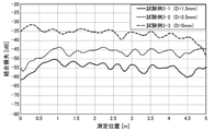
- FIG. 6 shows the relationship between the inner diameter of the outer conductor 4 (the outer diameter of the insulator 3) and the coupling loss.
- the outer diameters of the inner conductor 2 are 0.6 mm, 1 mm, and 2 mm, respectively.
- the outer diameter (D) of the insulator 3 is 1.5 mm, 2.5 mm, and 5 mm.
- the outer diameter of the outer conductor 4 is substantially the same as the value obtained by adding twice the thickness of the outer conductor 4 to the outer diameter of the insulator 3. The following conditions were common to Test Examples 3-1 to 3-3.
- the coupling loss was measured by arranging the measuring instrument (dipole antenna) 1.5 m away from each leaky coaxial cable 1 and moving the measuring instrument in the longitudinal direction with respect to the leaky coaxial cable 1.
- the horizontal axis indicates the position of the measuring instrument in the longitudinal direction. Specifically, the point where the horizontal axis is 0 m corresponds to the first end portion 1a of the leaky coaxial cable 1, and the point where the horizontal axis is 5 m corresponds to the second end portion 1b of the leaky coaxial cable 1.
- the coupling loss is 40 dB or less in most regions in the longitudinal direction.
- the coupling loss is 40 dB or less in most regions in the longitudinal direction.
- the coupling loss can be adjusted to 40 dB or less over the entire length of the leaky coaxial cable 1 in the longitudinal direction.
- Condition A The longitudinal dimension W1 is 10 mm or more, the peripheral aperture ratio R is within the range of 35 to 95%, and the outer diameter D of the insulator 3 is 5 mm or more.
- Condition B The longitudinal dimension W1 is 30 mm or more, the peripheral aperture ratio R is within the range of 70 to 95%, and the outer diameter D of the insulator 3 is 5 mm or more.
- Test Examples 4-1 and 4-2 shown in FIG. 7 the following conditions are common.
- the foaming rate of the foamed polyethylene, which is the material of the insulator 3 is different from the foaming rate in Test Example 3-1 and the like, so that the wavelength shortening rate is also different.
- Signal frequency 920MHz
- the peripheral dimension W2 is different between Test Example 4-1 and Test Example 4-2.
- Test Example 4-1 all the peripheral dimensions W2 of the five slots 4a are common (28 mm).
- Test Example 4-2 as shown in FIG. 2, the peripheral dimension W2 is larger in the slot 4a closer to the second end portion 1b. More specifically, the peripheral dimension W2 of the first and second slots 4a counting from the signal source side is 17 mm. The peripheral dimension W2 of the third and fourth slots 4a counting from the signal source side is 20 mm. The peripheral dimension W2 of the fifth slot 4a (closest to the second end 1b) counting from the signal source side is 28 mm.
- the slot pitch P satisfies the following equation (3). ⁇ g / (1 + 0.766 ⁇ ) ⁇ P ⁇ 3 ⁇ g / (1 + ⁇ )... (3)
- ⁇ g is the propagation wavelength in the leaky coaxial cable 1
- ⁇ g ⁇ .
- the range of the slot pitch P is preferably 161 mm to 434 mm.
- the leaky coaxial cable 1 includes an inner conductor 2, an insulator 3 that covers the inner conductor 2, and an outer conductor 4 that covers the insulator 3 and has at least one slot 4a formed therein. Then, the total length of the internal conductor 2 (leakage coaxial cable 1) in the longitudinal direction is set to 10 m or less, the longitudinal dimension W1 of the slot 4a is set to 10 mm or more, and the peripheral dimension W2 of the slot 4a is set with respect to the total length in the circumferential direction of the outer conductor 4. The range is 35 to 95%, and the outer diameter D of the insulator 3 is 5 mm or more. As a result, the coupling loss can be reduced to 40 dB or less. This makes it possible to provide a leaky coaxial cable 1 that can be used as an antenna for performing RFID communication in the UHF band.
- a plurality of slots 4a may be formed in the outer conductor 4 at intervals in the longitudinal direction. In this case, it is possible to provide a leaky coaxial cable 1 capable of performing RFID communication in a wider range in the longitudinal direction.
- peripheral dimension W2 of each of the plurality of slots 4a may gradually increase in the propagation direction in which the signal propagates. In this case, the coupling loss can be made more even in the longitudinal direction.
- a plurality of slots 4a may be formed in the outer conductor 4, and the plurality of slots 4a may be repeatedly arranged in the longitudinal direction.
- the repeating dimension (slot pitch) of the arrangement of the slot 4a in the longitudinal direction is P
- the longitudinal dimension of the slot 4a is W1
- the wavelength of the signal transmitted by the leaky coaxial cable 1 is ⁇
- the wavelength shortening rate is ⁇ .
- the -1st order radiation from the leaky coaxial cable 1 can be made perpendicular to the longitudinal direction, and an electric field with little fluctuation in the longitudinal direction can be obtained.
- the leaky coaxial cable 1 is used as an antenna for communicating with a passive RFID tag.
- the application of the leaky coaxial cable 1 is not limited to such an application.
- the leaky coaxial cable 1 of the present embodiment is suitable for, for example, an application in which a coupling loss of 40 dB or less is required with a certain distance (for example, 0.5 m or more) from a communication object. Available.
- the leaky coaxial cable 1 may have a configuration other than the inner conductor 2, the insulator 3, the outer conductor 4, and the sheath.
Abstract
In the present invention, a leaky coaxial cable comprises an internal conductor, an insulator, and an external conductor. The insulator covers the internal conductor. The external conductor covers the insulator. At least one slot is formed in the external conductor. The total length in the length direction of the internal conductor is 10m or less. The length-direction dimension of each slot is at least 10mm. The dimension of the slots in the circumferential direction of the external conductor is within 35–95% of the total circumferential-direction length of the external conductor. The outer diameter of the insulator is at least 5mm.
Description
本発明は、漏洩同軸ケーブルに関する。
本願は、2020年7月20日に、日本に出願された特願2020-123971号に基づき優先権を主張し、その内容をここに援用する。 The present invention relates to a leaky coaxial cable.
The present application claims priority based on Japanese Patent Application No. 2020-123971 filed in Japan on July 20, 2020, the contents of which are incorporated herein by reference.
特許文献1には、内部導体と、絶縁体と、スロットが形成された外部導体と、を備える漏洩同軸ケーブルが開示されている。漏洩同軸ケーブルは、無線通信を行う送受信アンテナとして用いられる。
Patent Document 1 discloses a leaky coaxial cable including an inner conductor, an insulator, and an outer conductor in which a slot is formed. The leaky coaxial cable is used as a transmitting / receiving antenna for wireless communication.
例えばパッシブ型RFIDタグとの間で通信を効果的に行うには、漏洩同軸ケーブルの結合損失を十分に小さくすることが求められる。
For example, in order to effectively communicate with a passive RFID tag, it is required to sufficiently reduce the coupling loss of the leaky coaxial cable.
本発明は、このような事情を考慮してなされ、結合損失を抑制する漏洩同軸ケーブルを提供することを目的とする。
The present invention has been made in consideration of such circumstances, and an object of the present invention is to provide a leaky coaxial cable that suppresses coupling loss.
上記課題を解決するために、本発明の一態様に係る漏洩同軸ケーブルは、内部導体と、前記内部導体を覆う絶縁体と、前記絶縁体を覆い、少なくとも1つのスロットが形成された外部導体と、を備え、前記内部導体の長手方向における全長は、10m以下であり、前記スロットの前記長手方向における寸法は、10mm以上であり、前記スロットの、前記外部導体の周方向における寸法は、前記外部導体の前記周方向における全長に対して35~95%の範囲内であり、前記絶縁体の外径が、5mm以上である。
In order to solve the above problems, the leaky coaxial cable according to one aspect of the present invention includes an inner conductor, an insulator that covers the inner conductor, and an outer conductor that covers the insulator and has at least one slot formed therein. , The total length of the inner conductor in the longitudinal direction is 10 m or less, the dimension of the slot in the longitudinal direction is 10 mm or more, and the dimension of the slot in the circumferential direction of the outer conductor is the outer. It is within the range of 35 to 95% with respect to the total length of the conductor in the circumferential direction, and the outer diameter of the insulator is 5 mm or more.
上記態様によれば、漏洩同軸ケーブルの、長手方向における少なくとも一部において、結合損失を40dB以下とすることができる。これにより、パッシブ型RFIDタグとの間でUHF帯の無線通信を行うアンテナとして利用可能な漏洩同軸ケーブルを提供することが可能となる。
According to the above aspect, the coupling loss can be 40 dB or less in at least a part of the leakage coaxial cable in the longitudinal direction. This makes it possible to provide a leaky coaxial cable that can be used as an antenna for wireless communication in the UHF band with a passive RFID tag.
ここで、前記外部導体には、前記スロットを含む複数のスロットが、前記長手方向に間隔を空けて形成され、前記複数のスロットのそれぞれの前記周方向における寸法は、信号が伝搬する伝搬方向において漸次大きくなっていてもよい。
Here, a plurality of slots including the slot are formed in the outer conductor at intervals in the longitudinal direction, and the dimension of each of the plurality of slots in the circumferential direction is the propagation direction in which the signal propagates. It may be gradually increased.
この場合、漏洩同軸ケーブルの結合損失を長手方向においてより均等にすることができる。
In this case, the coupling loss of the leaky coaxial cable can be made more even in the longitudinal direction.
また、前記外部導体には、前記スロットを含む複数のスロットが、前記長手方向に間隔を空けて形成され、前記複数のスロットは、前記長手方向において繰り返し配置され、前記複数のスロットの繰り返し寸法をPとし、前記複数のスロットの前記長手方向における寸法をW1とし、前記漏洩同軸ケーブルによって伝送される信号の波長をλとし、波長短縮率をνとするとき、0.97×λν≦P≦1.03×λνおよび0.97×P/2≦W1≦1.03×P/2を満足してもよい。
Further, in the outer conductor, a plurality of slots including the slot are formed at intervals in the longitudinal direction, and the plurality of slots are repeatedly arranged in the longitudinal direction to determine the repeating dimension of the plurality of slots. When P is set, the dimension of the plurality of slots in the longitudinal direction is W1, the wavelength of the signal transmitted by the leaky coaxial cable is λ, and the wavelength shortening rate is ν, 0.97 × λν ≦ P ≦ 1. .03 × λν and 0.97 × P / 2 ≦ W1 ≦ 1.03 × P / 2 may be satisfied.
この場合、漏洩同軸ケーブルからの-1次の輻射を長手方向に対して垂直にすることができ、長手方向に変動の少ない電界を得ることができる。
In this case, the -1st order radiation from the leaky coaxial cable can be made perpendicular to the longitudinal direction, and an electric field with little fluctuation in the longitudinal direction can be obtained.
本発明の上記態様によれば、結合損失を抑制する漏洩同軸ケーブルを提供することができる。
According to the above aspect of the present invention, it is possible to provide a leaky coaxial cable that suppresses coupling loss.
(第1実施形態)
以下、第1実施形態の漏洩同軸ケーブルについて図面に基づいて説明する。
図1に示すように、漏洩同軸ケーブル1は、内部導体2と、絶縁体3と、外部導体4と、を備える。漏洩同軸ケーブル1は、第1端部1aおよび第2端部1bを有する。絶縁体3は、内部導体2を覆っている。外部導体4は、絶縁体3を覆っている。外部導体4には、複数のスロット4aが形成されている。複数のスロット4aの各々は、外部導体4を径方向において貫通する孔である。なお、外部導体4に形成されるスロット4aの数は1つでもよい。外部導体4等を保護するため、漏洩同軸ケーブル1は、外部導体4を被覆する不図示のシース(ゴム、樹脂など)を備えてもよい。 (First Embodiment)
Hereinafter, the leaky coaxial cable of the first embodiment will be described with reference to the drawings.
As shown in FIG. 1, the leakycoaxial cable 1 includes an inner conductor 2, an insulator 3, and an outer conductor 4. The leaky coaxial cable 1 has a first end portion 1a and a second end portion 1b. The insulator 3 covers the inner conductor 2. The outer conductor 4 covers the insulator 3. A plurality of slots 4a are formed in the outer conductor 4. Each of the plurality of slots 4a is a hole that penetrates the outer conductor 4 in the radial direction. The number of slots 4a formed in the outer conductor 4 may be one. In order to protect the outer conductor 4 and the like, the leaky coaxial cable 1 may include a sheath (rubber, resin, etc.) (not shown) that covers the outer conductor 4.
以下、第1実施形態の漏洩同軸ケーブルについて図面に基づいて説明する。
図1に示すように、漏洩同軸ケーブル1は、内部導体2と、絶縁体3と、外部導体4と、を備える。漏洩同軸ケーブル1は、第1端部1aおよび第2端部1bを有する。絶縁体3は、内部導体2を覆っている。外部導体4は、絶縁体3を覆っている。外部導体4には、複数のスロット4aが形成されている。複数のスロット4aの各々は、外部導体4を径方向において貫通する孔である。なお、外部導体4に形成されるスロット4aの数は1つでもよい。外部導体4等を保護するため、漏洩同軸ケーブル1は、外部導体4を被覆する不図示のシース(ゴム、樹脂など)を備えてもよい。 (First Embodiment)
Hereinafter, the leaky coaxial cable of the first embodiment will be described with reference to the drawings.
As shown in FIG. 1, the leaky
(方向定義)
本実施形態では、内部導体2または外部導体4の中心軸線Oに沿う方向を長手方向と称する。長手方向は、Z軸によって表される。長手方向から見て、中心軸線Oに交差する方向を径方向と称する。長手方向からみて、中心軸線O回りに周回する方向を周方向と称する。長手方向は、漏洩同軸ケーブル1において信号が伝搬する伝搬方向と平行である。漏洩同軸ケーブル1において、信号は、第1端部1aから第2端部1bに向けて伝搬する。長手方向に沿って、信号が伝搬する方向を、+Z方向または終端側と称する。+Z方向とは反対の方向を、-Z方向または信号源側と称する。 (Direction definition)
In the present embodiment, the direction along the central axis O of theinner conductor 2 or the outer conductor 4 is referred to as a longitudinal direction. The longitudinal direction is represented by the Z axis. The direction that intersects the central axis O when viewed from the longitudinal direction is referred to as a radial direction. When viewed from the longitudinal direction, the direction that orbits around the central axis O is referred to as the circumferential direction. The longitudinal direction is parallel to the propagation direction in which the signal propagates in the leaky coaxial cable 1. In the leaky coaxial cable 1, the signal propagates from the first end 1a to the second end 1b. The direction in which the signal propagates along the longitudinal direction is referred to as the + Z direction or the terminal side. The direction opposite to the + Z direction is referred to as the −Z direction or the signal source side.
本実施形態では、内部導体2または外部導体4の中心軸線Oに沿う方向を長手方向と称する。長手方向は、Z軸によって表される。長手方向から見て、中心軸線Oに交差する方向を径方向と称する。長手方向からみて、中心軸線O回りに周回する方向を周方向と称する。長手方向は、漏洩同軸ケーブル1において信号が伝搬する伝搬方向と平行である。漏洩同軸ケーブル1において、信号は、第1端部1aから第2端部1bに向けて伝搬する。長手方向に沿って、信号が伝搬する方向を、+Z方向または終端側と称する。+Z方向とは反対の方向を、-Z方向または信号源側と称する。 (Direction definition)
In the present embodiment, the direction along the central axis O of the
内部導体2は、銅などの金属により形成されている。内部導体2は、長手方向に沿って延びている。内部導体2は、複数の導体の細線を撚り合わせることで形成された撚線であってもよい。絶縁体3は、内部導体2を径方向における外側から覆っている。絶縁体3としては、発泡ポリエチレンなどの絶縁性を有する樹脂が用いられる。
The inner conductor 2 is made of a metal such as copper. The inner conductor 2 extends along the longitudinal direction. The inner conductor 2 may be a stranded wire formed by twisting fine wires of a plurality of conductors. The insulator 3 covers the inner conductor 2 from the outside in the radial direction. As the insulator 3, a resin having an insulating property such as foamed polyethylene is used.
内部導体2は、外部の信号源に電気的に接続され、信号源から供給される高周波信号を伝搬させる。高周波信号の伝搬に伴い、外部導体4に形成されたスロット4aを通して、電磁波が、漏洩同軸ケーブル1の外部に漏洩する。
The internal conductor 2 is electrically connected to an external signal source and propagates a high frequency signal supplied from the signal source. With the propagation of the high frequency signal, the electromagnetic wave leaks to the outside of the leaky coaxial cable 1 through the slot 4a formed in the outer conductor 4.
外部導体4は、絶縁体3を径方向における外側から覆っている。外部導体4は、例えば、金属(銅等)のテープを絶縁体3に巻き付けることで形成される。このため、外部導体4の内径は、絶縁体3の外径と略同じ、あるいは、絶縁体3の外径よりわずかに大きくなる。絶縁体3と外部導体4との間に、空気の層があってもよい。複数のスロット4aとなる貫通孔を、外部導体4となるテープに予め形成しておくことで、任意の配置および形状を有する複数のスロット4aを容易に形成できる。外部導体4の厚さ(径方向における寸法)は、例えば0.01~0.02mmである。
The outer conductor 4 covers the insulator 3 from the outside in the radial direction. The outer conductor 4 is formed, for example, by winding a metal (copper or the like) tape around the insulator 3. Therefore, the inner diameter of the outer conductor 4 is substantially the same as the outer diameter of the insulator 3, or slightly larger than the outer diameter of the insulator 3. There may be a layer of air between the insulator 3 and the outer conductor 4. By preliminarily forming through holes to be the plurality of slots 4a in the tape to be the outer conductor 4, a plurality of slots 4a having an arbitrary arrangement and shape can be easily formed. The thickness (dimension in the radial direction) of the outer conductor 4 is, for example, 0.01 to 0.02 mm.
外部導体4の内周面には、絶縁性基材と、絶縁性基材を外部導体4に接着させる接着層と、が設けられてもよい。絶縁性基材の材料としては、例えばポリエチレンテレフタレート(PET)等のポリエステル樹脂、あるいは、ポリプロピレンやポリエチレン等のポリオレフィン樹脂を採用できる。接着層の材料としては、例えばエチレン系アイオノマー樹脂を採用できる。絶縁性基材および接着層には、スロット4aに対応した開口が形成されていなくてもよい。
The inner peripheral surface of the outer conductor 4 may be provided with an insulating base material and an adhesive layer for adhering the insulating base material to the outer conductor 4. As the material of the insulating base material, for example, a polyester resin such as polyethylene terephthalate (PET) or a polyolefin resin such as polypropylene or polyethylene can be adopted. As the material of the adhesive layer, for example, an ethylene-based ionomer resin can be adopted. The insulating base material and the adhesive layer may not have an opening corresponding to the slot 4a.
複数のスロット4aは、長手方向に間隔を空けて形成されている。各スロット4aは、長手方向および周方向に沿って延びている。各スロット4aの形状は、径方向における外側から見て矩形状となっている。または、各スロット4aの形状は長円形状、平行四辺形状であってもよい。また、外部導体4となるテープを絶縁体3に巻き付ける前の、テープが平らな状態においても、各スロット4aの形状は、矩形状となっている。図1に示すように、本明細書では、長手方向におけるスロット4aの寸法を単に長手寸法W1と称する。周方向におけるスロット4aの寸法を単に周寸法W2と称する。
The plurality of slots 4a are formed at intervals in the longitudinal direction. Each slot 4a extends along the longitudinal and circumferential directions. The shape of each slot 4a is rectangular when viewed from the outside in the radial direction. Alternatively, the shape of each slot 4a may be an oval shape or a parallel quadrilateral shape. Further, even when the tape is flat before the tape serving as the outer conductor 4 is wound around the insulator 3, the shape of each slot 4a is rectangular. As shown in FIG. 1, in the present specification, the dimension of the slot 4a in the longitudinal direction is simply referred to as the longitudinal dimension W1. The dimension of the slot 4a in the circumferential direction is simply referred to as the circumferential dimension W2.
本実施形態では、漏洩同軸ケーブル1の第2端部1bに近いスロット4aほど、周寸法W2が大きくなっている。言い換えれば、複数のスロット4aの各々の周寸法W2は、信号が伝搬する伝搬方向において漸次大きくなっている。詳細は後述するが、このように複数のスロット4aを形成することで、漏洩同軸ケーブル1の結合損失を、長手方向においてより均一にすることができる。第2端部1bに近いスロット4aほど周寸法W2が大きくなる構成としては、図2のような構成も採用できる。図2の漏洩同軸ケーブル1では、周寸法W2が略等しい2つのスロット4aが長手方向に隣接して形成され、その終端側に、周寸法W2がより大きい2つのスロット4aが配置されている。なお、「略等しい」には製造誤差を取り除けば周寸法W2が等しいとみなせる場合も含まれる。
In the present embodiment, the peripheral dimension W2 is larger in the slot 4a closer to the second end 1b of the leaky coaxial cable 1. In other words, the peripheral dimension W2 of each of the plurality of slots 4a gradually increases in the propagation direction in which the signal propagates. Although the details will be described later, by forming the plurality of slots 4a in this way, the coupling loss of the leaky coaxial cable 1 can be made more uniform in the longitudinal direction. As a configuration in which the peripheral dimension W2 becomes larger as the slot 4a closer to the second end portion 1b, the configuration as shown in FIG. 2 can be adopted. In the leaky coaxial cable 1 of FIG. 2, two slots 4a having substantially the same peripheral dimension W2 are formed adjacent to each other in the longitudinal direction, and two slots 4a having a larger peripheral dimension W2 are arranged on the terminal side thereof. In addition, "substantially equal" includes the case where the peripheral dimension W2 can be regarded as equal if the manufacturing error is removed.
なお、上記のように各スロット4aの周寸法W2を異ならせることは必須ではない。つまり、図3に示すように、外部導体4に形成されるスロット4aのそれぞれの周寸法W2は、互いに同じであってもよい。また、各スロット4aの長手寸法W1は、互いに同じであってもよいし、互いに異なっていてもよい。
It is not essential to make the circumference dimension W2 of each slot 4a different as described above. That is, as shown in FIG. 3, the peripheral dimensions W2 of the slots 4a formed in the outer conductor 4 may be the same as each other. Further, the longitudinal dimension W1 of each slot 4a may be the same as or different from each other.
ここで、本実施形態の漏洩同軸ケーブル1は、例えばパッシブ型RFIDタグとの間で通信を行うアンテナとして使用される。パッシブ型RFIDタグでは、一般的に、UHF帯(例えば920MHz程度)の高周波信号が用いられる。このような高周波信号を用いて、漏洩同軸ケーブル1とパッシブ型RFIDタグとの間の間隔を例えば1m程度空けた状態で良好な通信状態を保つには、結合損失を40dB以下とすることが求められる。結合損失を小さくするには、漏洩同軸ケーブル1から放出される電磁波のエネルギーを高めることが求められる。また、上記のように、本実施形態の漏洩同軸ケーブル1は、放出される電磁波のエネルギーを高めた状態で用いられるため、例えば100mを超えるような長距離の伝送には適さない。パッシブ型RFIDタグとの間で通信を行うという用途を考慮すると、漏洩同軸ケーブル1の全長は、例えば10m以下であってもよい。
Here, the leaky coaxial cable 1 of the present embodiment is used as an antenna for communicating with, for example, a passive RFID tag. In the passive RFID tag, a high frequency signal in the UHF band (for example, about 920 MHz) is generally used. In order to maintain a good communication state with such a high-frequency signal used and the distance between the leaky coaxial cable 1 and the passive RFID tag is, for example, about 1 m, it is required that the coupling loss be 40 dB or less. Be done. In order to reduce the coupling loss, it is required to increase the energy of the electromagnetic wave emitted from the leaky coaxial cable 1. Further, as described above, since the leaky coaxial cable 1 of the present embodiment is used in a state where the energy of the emitted electromagnetic wave is increased, it is not suitable for long-distance transmission exceeding 100 m, for example. Considering the use of communicating with the passive RFID tag, the total length of the leaky coaxial cable 1 may be, for example, 10 m or less.
漏洩同軸ケーブル1は、TEMモードと呼ばれる電界により、エネルギーを伝搬する。外部導体4において、長手方向に沿って電流が流れる。周方向および長手方向に延びるスロット4aを外部導体4に形成することで、外部導体4に流れる電流が部分的に切られる。これにより、スロット4aの信号源側と終端側との間で電位差が生じ、漏洩同軸ケーブルの周囲に電界が発生し、漏洩同軸ケーブル1の外部にエネルギーが放出される。このエネルギーを大きくすることは、スロット4aの長手寸法W1および周寸法W2を大きくすることで実現できる。本願発明者らが鋭意検討した結果によれば、長手寸法W1を10mm以上とし、周寸法W2を外部導体4の全周(外部導体4の周方向における全長)の35%以上とすることが好ましい。以下、より詳しく説明する。
The leaky coaxial cable 1 propagates energy by an electric field called TEM mode. In the outer conductor 4, a current flows along the longitudinal direction. By forming the slot 4a extending in the circumferential direction and the longitudinal direction in the outer conductor 4, the current flowing through the outer conductor 4 is partially cut off. As a result, a potential difference is generated between the signal source side and the terminal side of the slot 4a, an electric field is generated around the leaky coaxial cable, and energy is released to the outside of the leaky coaxial cable 1. Increasing this energy can be realized by increasing the longitudinal dimension W1 and the peripheral dimension W2 of the slot 4a. According to the results of diligent studies by the inventors of the present application, it is preferable that the longitudinal dimension W1 is 10 mm or more and the peripheral dimension W2 is 35% or more of the entire circumference of the outer conductor 4 (total length in the circumferential direction of the outer conductor 4). .. Hereinafter, a more detailed description will be given.
図4に、長手寸法W1と結合損失との関係を示す。試験例1-1、1-2の条件は下記表1に示す通りである。表1における「外部導体の周長」は、外部導体4のスロット4aが形成されていない部分の周方向における全長を示している。「周開口率R」は、周寸法W2の、外部導体4の周長に対する割合である。
FIG. 4 shows the relationship between the longitudinal dimension W1 and the coupling loss. The conditions of Test Examples 1-1 and 1-2 are as shown in Table 1 below. The “perimeter of the outer conductor” in Table 1 indicates the total length in the circumferential direction of the portion of the outer conductor 4 in which the slot 4a is not formed. The "peripheral aperture ratio R" is the ratio of the peripheral dimension W2 to the peripheral length of the outer conductor 4.

図4に示すように、試験例1-1、1-2の各々において、スロット4aの長手寸法W1を異ならせて、結合損失を測定した。試験例1-1、1-2のいずれにおいても、長手寸法W1が50mm以下の領域では、長手寸法W1が大きいほど結合損失が小さくなる。これは、長手寸法W1が大きいほどスロット4aから漏洩する電磁波の量が大きくなるためである。また、試験例1-1における結合損失は、試験例1-2における結合損失よりも小さい傾向があった。これは、試験例1-1における周寸法W2および周開口率Rが、試験例1-2における周寸法W2および周開口率Rよりも大きいためである。
As shown in FIG. 4, in each of Test Examples 1-1 and 1-2, the longitudinal dimension W1 of the slot 4a was different, and the coupling loss was measured. In any of Test Examples 1-1 and 1-2, in the region where the longitudinal dimension W1 is 50 mm or less, the larger the longitudinal dimension W1, the smaller the coupling loss. This is because the larger the longitudinal dimension W1, the larger the amount of electromagnetic waves leaked from the slot 4a. Further, the binding loss in Test Example 1-1 tended to be smaller than the binding loss in Test Example 1-2. This is because the peripheral dimension W2 and the peripheral aperture ratio R in Test Example 1-1 are larger than the peripheral dimension W2 and the peripheral aperture ratio R in Test Example 1-2.
試験例1-1の条件(R=83%)では、長手寸法W1を10mm以上とすることで、結合損失を40dB以下とすることができた。試験例1-2の条件(R=70%)では、長手寸法W1を30mm以上とすることで、結合損失を40dB以下とすることができた。なお、長手寸法W1の上限値については任意である。例えば、複数のスロット4aを形成する場合に、スロット4a同士が長手方向に間隔を空けて形成されるように設定するのが好適である。
Under the conditions of Test Example 1-1 (R = 83%), the coupling loss could be 40 dB or less by setting the longitudinal dimension W1 to 10 mm or more. Under the conditions of Test Example 1-2 (R = 70%), the coupling loss could be 40 dB or less by setting the longitudinal dimension W1 to 30 mm or more. The upper limit of the longitudinal dimension W1 is arbitrary. For example, when forming a plurality of slots 4a, it is preferable to set the slots 4a so that they are formed at intervals in the longitudinal direction.
図5に、周開口率Rと結合損失との関係を示す。試験例2では、外部導体4の外径を10mmとし、スロット4aの数を1つとし、長手寸法W1を100mmとした。そして、周寸法W2(周開口率R)を異ならせて、結合損失を測定した。図5に示すように、周開口率Rが大きいほど、結合損失が小さくなる。試験例2の条件では、周開口率Rを35%以上とすることで、結合損失を40dB以下とすることができた。
FIG. 5 shows the relationship between the peripheral aperture ratio R and the coupling loss. In Test Example 2, the outer diameter of the outer conductor 4 is 10 mm, the number of slots 4a is one, and the longitudinal dimension W1 is 100 mm. Then, the peripheral dimension W2 (peripheral aperture ratio R) was made different, and the coupling loss was measured. As shown in FIG. 5, the larger the peripheral aperture ratio R, the smaller the coupling loss. Under the conditions of Test Example 2, the coupling loss could be 40 dB or less by setting the peripheral aperture ratio R to 35% or more.
スロット4aを1つのみ有する漏洩同軸ケーブルにおいて結合損失を低下させるという観点では、周開口率Rが大きいほど好ましい。一方、複数のスロット4aを有する漏洩同軸ケーブルにおいては、スロット4aの周開口率Rが大きすぎると、スロット4aが形成された部分における伝送損失が大きくなる。これにより、第2端部1bに近いスロット4aに供給される信号が有するエネルギーが極端に少なくなる。目安として、周開口率Rは95%以下とすることが好ましい。周開口率Rが95%以下であれば、第2端部1bに近いスロット4aに供給される信号においても適度なエネルギーが確保され、漏洩同軸ケーブル全体として結合損失を低くできる。
From the viewpoint of reducing the coupling loss in a leaky coaxial cable having only one slot 4a, a larger peripheral aperture ratio R is preferable. On the other hand, in a leaky coaxial cable having a plurality of slots 4a, if the peripheral aperture ratio R of the slots 4a is too large, the transmission loss in the portion where the slots 4a is formed becomes large. As a result, the energy of the signal supplied to the slot 4a near the second end 1b is extremely reduced. As a guide, the peripheral aperture ratio R is preferably 95% or less. When the peripheral aperture ratio R is 95% or less, appropriate energy is secured even in the signal supplied to the slot 4a near the second end 1b, and the coupling loss can be reduced for the entire leakage coaxial cable.
図6に、外部導体4の内径(絶縁体3の外径)と結合損失との関係を示す。試験例3-1~3-3においては、それぞれ、内部導体2の外径を0.6mm、1mm、および2mmとしている。また、絶縁体3の外径(D)を1.5mm、2.5mm、および5mmとしている。なお、外部導体4の外径は、絶縁体3の外径に、外部導体4の厚さの2倍を足した値とほぼ同じになる。試験例3-1~3-3において、以下の条件は共通とした。
漏洩同軸ケーブル1の全長:5m
絶縁体3の材質:発泡ポリエチレン(波長短縮率0.8)
長手寸法W1:110mm
周開口率R:80%
径方向における外側からみたスロット4aの形状:矩形状
スロット4aの数:21
長手方向におけるスロット4a同士の間の間隔:128mm
信号の周波数:920MHz FIG. 6 shows the relationship between the inner diameter of the outer conductor 4 (the outer diameter of the insulator 3) and the coupling loss. In Test Examples 3-1 to 3-3, the outer diameters of theinner conductor 2 are 0.6 mm, 1 mm, and 2 mm, respectively. Further, the outer diameter (D) of the insulator 3 is 1.5 mm, 2.5 mm, and 5 mm. The outer diameter of the outer conductor 4 is substantially the same as the value obtained by adding twice the thickness of the outer conductor 4 to the outer diameter of the insulator 3. The following conditions were common to Test Examples 3-1 to 3-3.
Overall length of leaky coaxial cable 1: 5m
Material of insulator 3: Polyethylene foam (wavelength shortening rate 0.8)
Longitudinal dimension W1: 110mm
Peripheral aperture ratio R: 80%
Shape ofslot 4a seen from the outside in the radial direction: Number of rectangular slots 4a: 21
Spacing betweenslots 4a in the longitudinal direction: 128 mm
Signal frequency: 920MHz
漏洩同軸ケーブル1の全長:5m
絶縁体3の材質:発泡ポリエチレン(波長短縮率0.8)
長手寸法W1:110mm
周開口率R:80%
径方向における外側からみたスロット4aの形状:矩形状
スロット4aの数:21
長手方向におけるスロット4a同士の間の間隔:128mm
信号の周波数:920MHz FIG. 6 shows the relationship between the inner diameter of the outer conductor 4 (the outer diameter of the insulator 3) and the coupling loss. In Test Examples 3-1 to 3-3, the outer diameters of the
Overall length of leaky coaxial cable 1: 5m
Material of insulator 3: Polyethylene foam (wavelength shortening rate 0.8)
Longitudinal dimension W1: 110mm
Peripheral aperture ratio R: 80%
Shape of
Spacing between
Signal frequency: 920MHz
なお、結合損失の測定は、測定器(ダイポールアンテナ)を各漏洩同軸ケーブル1から1.5m離して配置し、測定器を漏洩同軸ケーブル1に対して長手方向に移動させることで行った。図6において、横軸(測定位置)は測定器の長手方向における位置を示している。具体的に、横軸が0mのポイントが漏洩同軸ケーブル1の第1端部1aに対応し、横軸が5mのポイントが漏洩同軸ケーブル1の第2端部1bに対応している。
The coupling loss was measured by arranging the measuring instrument (dipole antenna) 1.5 m away from each leaky coaxial cable 1 and moving the measuring instrument in the longitudinal direction with respect to the leaky coaxial cable 1. In FIG. 6, the horizontal axis (measurement position) indicates the position of the measuring instrument in the longitudinal direction. Specifically, the point where the horizontal axis is 0 m corresponds to the first end portion 1a of the leaky coaxial cable 1, and the point where the horizontal axis is 5 m corresponds to the second end portion 1b of the leaky coaxial cable 1.
図6に示すように、絶縁体3の外径Dが大きいほど、結合損失が小さくなった。特に、絶縁体3の外径Dが5mmである試験例3-3では、長手方向におけるほとんどの領域で、結合損失が40dB以下となった。なお、試験例3-3のように、長手方向における一部の領域で結合損失が40dBを超えても、パッシブ型RFIDタグとの間で通信を行うことは可能である。例えば、漏洩同軸ケーブル1のうち結合損失が40dB以下の領域(試験例3-3では長手方向における位置が0~4.7mの領域)だけを通信用アンテナとして使用すれば足りるためである。あるいは、漏洩同軸ケーブル1とパッシブ型RFIDタグとの間の間隔を、1.5mよりも小さくすれば、漏洩同軸ケーブル1の長手方向の全長にわたって結合損失を40dB以下に調整できるためである。
As shown in FIG. 6, the larger the outer diameter D of the insulator 3, the smaller the coupling loss. In particular, in Test Example 3-3 in which the outer diameter D of the insulator 3 is 5 mm, the coupling loss is 40 dB or less in most regions in the longitudinal direction. As in Test Example 3-3, even if the coupling loss exceeds 40 dB in a part of the longitudinal direction, it is possible to communicate with the passive RFID tag. For example, it is sufficient to use only the region of the leakage coaxial cable 1 in which the coupling loss is 40 dB or less (the region where the position in the longitudinal direction is 0 to 4.7 m in Test Example 3-3) as the communication antenna. Alternatively, if the distance between the leaky coaxial cable 1 and the passive RFID tag is made smaller than 1.5 m, the coupling loss can be adjusted to 40 dB or less over the entire length of the leaky coaxial cable 1 in the longitudinal direction.
ここで、一般的に、長手寸法W1が同じ場合、絶縁体3の外径Dとスロット4aのうち周方向に延びるエッジの長さとの比率で結合損失が決まる。このため、周開口率Rが互いに等しい試験例3-1~3-3においては、結合損失も等しくなると考えられる。しかし、試験例3-1~3-3ではそのような結果が得られず、絶縁体3の外径Dが大きいほど結合損失が小さくなった。その理由として、前記エッジが、外部導体4の他の部分と結合することにより、インピーダンスが上がらないことが考えられる。例えば、試験例3-1~3-3においてスロット4aの形状は矩形状であるため、角部が略直角に曲がっている。このため、スロット4aのうち周方向に延びるエッジと、長手方向に延びるエッジとが容量結合する可能性がある。この場合、電流が、外部導体4を通らず絶縁体3中を進む可能性がある。あるいは、前記エッジの中間部分が、内部導体2と結合することが考えられる。このような現象が生じると、外径Dが大きくても実効的なエッジ部長が短くなり、結合損失が下がらないと考えられる。
Here, in general, when the longitudinal dimension W1 is the same, the coupling loss is determined by the ratio between the outer diameter D of the insulator 3 and the length of the edge extending in the circumferential direction of the slot 4a. Therefore, in Test Examples 3-1 to 3-3 in which the peripheral aperture ratios R are equal to each other, it is considered that the coupling loss is also equal. However, such a result was not obtained in Test Examples 3-1 to 3-3, and the larger the outer diameter D of the insulator 3, the smaller the coupling loss. It is conceivable that the reason is that the impedance does not increase due to the edge being coupled to the other portion of the outer conductor 4. For example, in Test Examples 3-1 to 3-3, since the shape of the slot 4a is rectangular, the corners are bent at substantially right angles. Therefore, there is a possibility that the edge extending in the circumferential direction and the edge extending in the longitudinal direction of the slot 4a are capacitively coupled. In this case, the current may travel through the insulator 3 without passing through the outer conductor 4. Alternatively, it is conceivable that the intermediate portion of the edge is coupled to the inner conductor 2. When such a phenomenon occurs, it is considered that the effective edge length is shortened even if the outer diameter D is large, and the coupling loss is not reduced.
図4~図6の結果を総合すると、結合損失を40dB以下に抑制するためには、以下の条件Aまたは条件Bを満たすことが好ましい。
条件A:長手寸法W1を10mm以上とし、周開口率Rを35~95%の範囲内とし、絶縁体3の外径Dを5mm以上とする。
条件B:長手寸法W1を30mm以上とし、周開口率Rを70~95%の範囲内とし、絶縁体3の外径Dを5mm以上とする。 Summing up the results of FIGS. 4 to 6, it is preferable to satisfy the following condition A or condition B in order to suppress the binding loss to 40 dB or less.
Condition A: The longitudinal dimension W1 is 10 mm or more, the peripheral aperture ratio R is within the range of 35 to 95%, and the outer diameter D of theinsulator 3 is 5 mm or more.
Condition B: The longitudinal dimension W1 is 30 mm or more, the peripheral aperture ratio R is within the range of 70 to 95%, and the outer diameter D of theinsulator 3 is 5 mm or more.
条件A:長手寸法W1を10mm以上とし、周開口率Rを35~95%の範囲内とし、絶縁体3の外径Dを5mm以上とする。
条件B:長手寸法W1を30mm以上とし、周開口率Rを70~95%の範囲内とし、絶縁体3の外径Dを5mm以上とする。 Summing up the results of FIGS. 4 to 6, it is preferable to satisfy the following condition A or condition B in order to suppress the binding loss to 40 dB or less.
Condition A: The longitudinal dimension W1 is 10 mm or more, the peripheral aperture ratio R is within the range of 35 to 95%, and the outer diameter D of the
Condition B: The longitudinal dimension W1 is 30 mm or more, the peripheral aperture ratio R is within the range of 70 to 95%, and the outer diameter D of the
次に、図7を用いて、第2端部1bに近いスロット4aほど周寸法W2を大きくすることの効果について説明する。図7に示す試験例4-1、4-2においては、以下の条件については共通である。なお、試験例4-1、4-2では、絶縁体3の材質である発泡ポリエチレンの発泡率が試験例3-1等における発泡率とは異なっているため、波長短縮率も異なっている。
漏洩同軸ケーブル1の長さ:1m
内部導体2の外径:4.3mm
絶縁体3の外径D:10mm
絶縁体3の材質:発泡ポリエチレン(波長短縮率0.87)
長手寸法W1:100mm
径方向における外側からみたスロット4aの形状:矩形状
スロット4aの数:5
長手方向におけるスロット4a同士の間の間隔:128mm
信号の周波数:920MHz Next, with reference to FIG. 7, the effect of increasing the peripheral dimension W2 toward theslot 4a closer to the second end portion 1b will be described. In Test Examples 4-1 and 4-2 shown in FIG. 7, the following conditions are common. In Test Examples 4-1 and 4-2, the foaming rate of the foamed polyethylene, which is the material of the insulator 3, is different from the foaming rate in Test Example 3-1 and the like, so that the wavelength shortening rate is also different.
Leakagecoaxial cable 1 length: 1 m
Outer diameter of inner conductor 2: 4.3 mm
Outer diameter D of insulator 3: 10 mm
Material of insulator 3: Polyethylene foam (wavelength shortening rate 0.87)
Longitudinal dimension W1: 100 mm
Shape ofslot 4a seen from the outside in the radial direction: Number of rectangular slots 4a: 5
Spacing betweenslots 4a in the longitudinal direction: 128 mm
Signal frequency: 920MHz
漏洩同軸ケーブル1の長さ:1m
内部導体2の外径:4.3mm
絶縁体3の外径D:10mm
絶縁体3の材質:発泡ポリエチレン(波長短縮率0.87)
長手寸法W1:100mm
径方向における外側からみたスロット4aの形状:矩形状
スロット4aの数:5
長手方向におけるスロット4a同士の間の間隔:128mm
信号の周波数:920MHz Next, with reference to FIG. 7, the effect of increasing the peripheral dimension W2 toward the
Leakage
Outer diameter of inner conductor 2: 4.3 mm
Outer diameter D of insulator 3: 10 mm
Material of insulator 3: Polyethylene foam (wavelength shortening rate 0.87)
Longitudinal dimension W1: 100 mm
Shape of
Spacing between
Signal frequency: 920MHz
一方、試験例4-1と試験例4-2との間では、表2に示すように、周寸法W2が異なっている。試験例4-1においては、5つのスロット4aの全ての周寸法W2が共通(28mm)である。試験例4-2においては、図2に示すように、第2端部1bに近いスロット4aほど周寸法W2が大きくなっている。より詳しくは、信号源側から数えて1番目および2番目のスロット4aの周寸法W2が17mmである。信号源側から数えて3番目および4番目のスロット4aの周寸法W2が20mmである。信号源側から数えて5番目の(最も第2端部1bに近い)スロット4aの周寸法W2が28mmである。
On the other hand, as shown in Table 2, the peripheral dimension W2 is different between Test Example 4-1 and Test Example 4-2. In Test Example 4-1 all the peripheral dimensions W2 of the five slots 4a are common (28 mm). In Test Example 4-2, as shown in FIG. 2, the peripheral dimension W2 is larger in the slot 4a closer to the second end portion 1b. More specifically, the peripheral dimension W2 of the first and second slots 4a counting from the signal source side is 17 mm. The peripheral dimension W2 of the third and fourth slots 4a counting from the signal source side is 20 mm. The peripheral dimension W2 of the fifth slot 4a (closest to the second end 1b) counting from the signal source side is 28 mm.

図7に示した試験例4-1、4-2に係る結合損失は、シミュレーションに基づいている。図7の横軸は長手方向における位置である。図7に示すように、試験例4-1、4-2のいずれにおいても、結合損失を40dB以下とすることができた。ただし、試験例4-1においては、終端側(+Z側)に向かう方向において、漸次結合損失が低下している。これは、信号が終端側に向けて伝搬するに従って電磁波が漏洩し、外部導体4内を流れる信号の強度が減衰するためである。一方、試験例4-2においては、長手方向において結合損失をより均等にすることができた。これは、第2端部1bに近いスロット4aほど周寸法W2を大きくして電磁波を漏洩させやすくする構成を採用することで、外部導体4を流れる信号の強度が信号の流れる方向において減衰することを打ち消したためである。このように、第2端部1bに近いスロット4aほど周寸法W2を大きくする構成を採用することで、長手方向において結合損失をより均等にすることができる。
The coupling loss according to Test Examples 4-1 and 4-2 shown in FIG. 7 is based on a simulation. The horizontal axis of FIG. 7 is a position in the longitudinal direction. As shown in FIG. 7, in any of Test Examples 4-1 and 4-2, the binding loss could be 40 dB or less. However, in Test Example 4-1 the gradual coupling loss decreases in the direction toward the terminal side (+ Z side). This is because the electromagnetic wave leaks as the signal propagates toward the terminal side, and the strength of the signal flowing in the outer conductor 4 is attenuated. On the other hand, in Test Example 4-2, the bond loss could be made more even in the longitudinal direction. This is because the strength of the signal flowing through the outer conductor 4 is attenuated in the direction in which the signal flows by adopting a configuration in which the peripheral dimension W2 is increased toward the slot 4a closer to the second end portion 1b to facilitate leakage of electromagnetic waves. This is because it was canceled. As described above, by adopting a configuration in which the peripheral dimension W2 is increased by the slot 4a closer to the second end portion 1b, the coupling loss can be made more uniform in the longitudinal direction.
次に、外部導体4に複数のスロット4aを設ける場合における、好ましいスロットピッチPの範囲について説明する。本明細書において「スロットピッチP」とは、長手方向におけるスロット4aの配置の繰り返し寸法である。より詳しくは、スロットピッチPは、長手寸法W1と、スロット4a同士の間の間隔と、の和である。例えば先述の試験例4-1では、長手寸法W1が100mmでスロット4a間の間隔が128mmのため、P=100+128=228mmである。
Next, a range of preferable slot pitch P when a plurality of slots 4a are provided in the outer conductor 4 will be described. As used herein, the "slot pitch P" is a repeating dimension of the arrangement of slots 4a in the longitudinal direction. More specifically, the slot pitch P is the sum of the longitudinal dimension W1 and the distance between the slots 4a. For example, in Test Example 4-1 described above, since the longitudinal dimension W1 is 100 mm and the distance between the slots 4a is 128 mm, P = 100 + 128 = 228 mm.
一般に、漏洩同軸ケーブル1からの電磁波の方射角θnは、中心軸線Oに直角な方射角を0として、終端側に傾いた放射角を正とすれば、以下の式(1)で表される。
θn=sin-1(nλ/P+1/ν) …(1)
ただし、nは放射モード(負の整数)、λは自由空間での波長、νは漏洩同軸ケーブル1の波長短縮率である。波長短縮率νは、内部導体2と外部導体4との間の領域における絶縁体3と中空部分との体積比から求めた実効比誘電率εsに基づき、以下の式(2)で表される。
ν=1/(εs)1/2 …(2) Generally, the radial angle θn of the electromagnetic wave from the leakycoaxial cable 1 is expressed by the following equation (1), where the radial angle perpendicular to the central axis O is 0 and the radiation angle inclined toward the terminal side is positive. Will be done.
θn = sin -1 (nλ / P + 1 / ν)… (1)
However, n is the radiation mode (negative integer), λ is the wavelength in free space, and ν is the wavelength shortening rate of the leakycoaxial cable 1. The wavelength shortening rate ν is expressed by the following equation (2) based on the effective specific permittivity εs obtained from the volume ratio of the insulator 3 and the hollow portion in the region between the inner conductor 2 and the outer conductor 4. ..
ν = 1 / (εs) 1/2 ... (2)
θn=sin-1(nλ/P+1/ν) …(1)
ただし、nは放射モード(負の整数)、λは自由空間での波長、νは漏洩同軸ケーブル1の波長短縮率である。波長短縮率νは、内部導体2と外部導体4との間の領域における絶縁体3と中空部分との体積比から求めた実効比誘電率εsに基づき、以下の式(2)で表される。
ν=1/(εs)1/2 …(2) Generally, the radial angle θn of the electromagnetic wave from the leaky
θn = sin -1 (nλ / P + 1 / ν)… (1)
However, n is the radiation mode (negative integer), λ is the wavelength in free space, and ν is the wavelength shortening rate of the leaky
ν = 1 / (εs) 1/2 ... (2)
通常は、n=-1のいわゆる-1次モードだけが使用されることが多い。経験的に、-1次モードの方射角としては、-50°~+30°が実用的な限界範囲である。したがって、スロットピッチPは、以下の式(3)を満足することが好ましい。
λg/(1+0.766ν)<P<3λg/(1+ν) …(3)
ここで、λgは漏洩同軸ケーブル1内での伝搬波長であり、λg=νλである。
例えば、信号の周波数が920MHz(λ≒325.9mm)、波長短縮率νが0.8である条件においては、スロットピッチPの範囲は、161mm~434mmであることが好ましい。 Usually, only the so-called -1st order mode of n = -1 is often used. Empirically, -50 ° to + 30 ° is a practical limit range for the direction angle of the -1st mode. Therefore, it is preferable that the slot pitch P satisfies the following equation (3).
λg / (1 + 0.766ν) <P <3λg / (1 + ν)… (3)
Here, λg is the propagation wavelength in the leakycoaxial cable 1, and λg = νλ.
For example, under the condition that the frequency of the signal is 920 MHz (λ≈325.9 mm) and the wavelength shortening rate ν is 0.8, the range of the slot pitch P is preferably 161 mm to 434 mm.
λg/(1+0.766ν)<P<3λg/(1+ν) …(3)
ここで、λgは漏洩同軸ケーブル1内での伝搬波長であり、λg=νλである。
例えば、信号の周波数が920MHz(λ≒325.9mm)、波長短縮率νが0.8である条件においては、スロットピッチPの範囲は、161mm~434mmであることが好ましい。 Usually, only the so-called -1st order mode of n = -1 is often used. Empirically, -50 ° to + 30 ° is a practical limit range for the direction angle of the -1st mode. Therefore, it is preferable that the slot pitch P satisfies the following equation (3).
λg / (1 + 0.766ν) <P <3λg / (1 + ν)… (3)
Here, λg is the propagation wavelength in the leaky
For example, under the condition that the frequency of the signal is 920 MHz (λ≈325.9 mm) and the wavelength shortening rate ν is 0.8, the range of the slot pitch P is preferably 161 mm to 434 mm.
以上説明したように、漏洩同軸ケーブル1は、内部導体2と、内部導体2を覆う絶縁体3と、絶縁体3を覆い、少なくとも1つのスロット4aが形成された外部導体4と、を備える。そして、長手方向における内部導体2(漏洩同軸ケーブル1)の全長を10m以下とし、スロット4aの長手寸法W1を10mm以上とし、スロット4aの周寸法W2を外部導体4の周方向における全長に対して35~95%の範囲内とし、絶縁体3の外径Dを5mm以上とする。これにより、結合損失を40dB以下とすることができる。これにより、UHF帯のRFID通信を行うアンテナとして利用可能な漏洩同軸ケーブル1を提供することが可能となる。
As described above, the leaky coaxial cable 1 includes an inner conductor 2, an insulator 3 that covers the inner conductor 2, and an outer conductor 4 that covers the insulator 3 and has at least one slot 4a formed therein. Then, the total length of the internal conductor 2 (leakage coaxial cable 1) in the longitudinal direction is set to 10 m or less, the longitudinal dimension W1 of the slot 4a is set to 10 mm or more, and the peripheral dimension W2 of the slot 4a is set with respect to the total length in the circumferential direction of the outer conductor 4. The range is 35 to 95%, and the outer diameter D of the insulator 3 is 5 mm or more. As a result, the coupling loss can be reduced to 40 dB or less. This makes it possible to provide a leaky coaxial cable 1 that can be used as an antenna for performing RFID communication in the UHF band.
また、外部導体4には、複数のスロット4aが長手方向に間隔を空けて形成されていてもよい。この場合、長手方向におけるより広い範囲でRFID通信を行うことが可能な漏洩同軸ケーブル1を提供することができる。
Further, a plurality of slots 4a may be formed in the outer conductor 4 at intervals in the longitudinal direction. In this case, it is possible to provide a leaky coaxial cable 1 capable of performing RFID communication in a wider range in the longitudinal direction.
また、複数のスロット4aのそれぞれの周寸法W2は、信号が伝搬する伝搬方向において漸次大きくなっていてもよい。この場合、結合損失を長手方向においてより均等にすることができる。
Further, the peripheral dimension W2 of each of the plurality of slots 4a may gradually increase in the propagation direction in which the signal propagates. In this case, the coupling loss can be made more even in the longitudinal direction.
また、外部導体4には複数のスロット4aが形成され、複数のスロット4aは、長手方向において繰り返し配置されてもよい。スロット4aの長手方向における配置の繰り返し寸法(スロットピッチ)をPとし、スロット4aの長手寸法をW1とし、漏洩同軸ケーブル1によって伝送される信号の波長をλとし、波長短縮率をνとするとき、0.97×λν≦P≦1.03×λνおよび0.97×P/2≦W1≦1.03×P/2を満足してもよい。この場合、漏洩同軸ケーブル1からの-1次の輻射を長手方向に対して垂直にすることができ、長手方向に変動の少ない電界を得ることができる。
Further, a plurality of slots 4a may be formed in the outer conductor 4, and the plurality of slots 4a may be repeatedly arranged in the longitudinal direction. When the repeating dimension (slot pitch) of the arrangement of the slot 4a in the longitudinal direction is P, the longitudinal dimension of the slot 4a is W1, the wavelength of the signal transmitted by the leaky coaxial cable 1 is λ, and the wavelength shortening rate is ν. , 0.97 × λν ≦ P ≦ 1.03 × λν and 0.97 × P / 2 ≦ W1 ≦ 1.03 × P / 2. In this case, the -1st order radiation from the leaky coaxial cable 1 can be made perpendicular to the longitudinal direction, and an electric field with little fluctuation in the longitudinal direction can be obtained.
なお、本発明の技術的範囲は、前記実施形態に限定されず、本発明の趣旨を逸脱しない範囲において種々の変更を加えることが可能である。
The technical scope of the present invention is not limited to the above-described embodiment, and various modifications can be made without departing from the spirit of the present invention.
例えば、前記実施形態では、漏洩同軸ケーブル1がパッシブ型RFIDタグとの通信を行うアンテナとして利用されると説明した。しかしながら、漏洩同軸ケーブル1の用途はこのような用途に限られない。本実施形態の漏洩同軸ケーブル1は、例えば、通信対象物との間である程度(例えば0.5m以上)の距離を空けた状態で結合損失を40dB以下とすることが求められる用途に、好適に利用できる。漏洩同軸ケーブル1の用途に合わせて、漏洩同軸ケーブル1が、内部導体2、絶縁体3、外部導体4、およびシース以外の構成を備えてもよい。
For example, in the above embodiment, it has been explained that the leaky coaxial cable 1 is used as an antenna for communicating with a passive RFID tag. However, the application of the leaky coaxial cable 1 is not limited to such an application. The leaky coaxial cable 1 of the present embodiment is suitable for, for example, an application in which a coupling loss of 40 dB or less is required with a certain distance (for example, 0.5 m or more) from a communication object. Available. Depending on the application of the leaky coaxial cable 1, the leaky coaxial cable 1 may have a configuration other than the inner conductor 2, the insulator 3, the outer conductor 4, and the sheath.
その他、本発明の趣旨を逸脱しない範囲で、上記した実施形態における構成要素を周知の構成要素に置き換えることは適宜可能であり、また、上記した実施形態や変形例を適宜組み合わせてもよい。
In addition, it is possible to replace the constituent elements in the above-described embodiment with well-known constituent elements as appropriate without departing from the spirit of the present invention, and the above-described embodiments and modifications may be appropriately combined.
1…漏洩同軸ケーブル 2…内部導体 3…絶縁体 4…外部導体 4a…スロット D…絶縁体の外径 Z…長手方向 W1…長手寸法(長手方向における寸法) W2…周寸法(周方向における寸法)
1 ... Leakage coaxial cable 2 ... Internal conductor 3 ... Insulator 4 ... External conductor 4a ... Slot D ... Insulator outer diameter Z ... Longitudinal direction W1 ... Longitudinal dimension (dimension in longitudinal direction) W2 ... Circumferential dimension (dimension in circumferential direction) )
Claims (3)
- 内部導体と、
前記内部導体を覆う絶縁体と、
前記絶縁体を覆い、少なくとも1つのスロットが形成された外部導体と、を備え、
前記内部導体の長手方向における全長は、10m以下であり、
前記スロットの前記長手方向における寸法は、10mm以上であり、
前記スロットの、前記外部導体の周方向における寸法は、前記外部導体の前記周方向における全長に対して35~95%の範囲内であり、
前記絶縁体の外径が、5mm以上である、漏洩同軸ケーブル。 With the inner conductor,
The insulator that covers the inner conductor and
An external conductor covering the insulator and having at least one slot formed therein.
The total length of the internal conductor in the longitudinal direction is 10 m or less.
The dimension of the slot in the longitudinal direction is 10 mm or more.
The dimension of the slot in the circumferential direction of the outer conductor is in the range of 35 to 95% with respect to the total length of the outer conductor in the circumferential direction.
A leaky coaxial cable having an outer diameter of the insulator of 5 mm or more. - 前記外部導体には、前記スロットを含む複数のスロットが、前記長手方向に間隔を空けて形成され、
前記複数のスロットのそれぞれの前記周方向における寸法は、信号が伝搬する伝搬方向において漸次大きくなっている、請求項1に記載の漏洩同軸ケーブル。 A plurality of slots including the slot are formed in the outer conductor at intervals in the longitudinal direction.
The leaky coaxial cable according to claim 1, wherein the dimension of each of the plurality of slots in the circumferential direction is gradually increased in the propagation direction in which the signal propagates. - 前記外部導体には、前記スロットを含む複数のスロットが、前記長手方向に間隔を空けて形成され、
前記複数のスロットは、前記長手方向において繰り返し配置され、
前記複数のスロットの繰り返し寸法をPとし、前記複数のスロットのそれぞれの前記長手方向における寸法をW1とし、前記漏洩同軸ケーブルによって伝送される信号の波長をλとし、波長短縮率をνとするとき、0.97×λν≦P≦1.03×λνおよび0.97×P/2≦W1≦1.03×P/2を満足する、請求項1または2に記載の漏洩同軸ケーブル。 A plurality of slots including the slot are formed in the outer conductor at intervals in the longitudinal direction.
The plurality of slots are repeatedly arranged in the longitudinal direction, and the plurality of slots are repeatedly arranged in the longitudinal direction.
When the repeating dimension of the plurality of slots is P, the dimension of each of the plurality of slots in the longitudinal direction is W1, the wavelength of the signal transmitted by the leaky coaxial cable is λ, and the wavelength shortening rate is ν. , 0.97 × λν ≦ P ≦ 1.03 × λν and 0.97 × P / 2 ≦ W1 ≦ 1.03 × P / 2, the leaky coaxial cable according to claim 1 or 2.
Applications Claiming Priority (2)
| Application Number | Priority Date | Filing Date | Title |
|---|---|---|---|
| JP2020-123971 | 2020-07-20 | ||
| JP2020123971A JP2022020462A (en) | 2020-07-20 | 2020-07-20 | Leakage coaxial cable |
Publications (1)
| Publication Number | Publication Date |
|---|---|
| WO2022019190A1 true WO2022019190A1 (en) | 2022-01-27 |
Family
ID=79728674
Family Applications (1)
| Application Number | Title | Priority Date | Filing Date |
|---|---|---|---|
| PCT/JP2021/026448 WO2022019190A1 (en) | 2020-07-20 | 2021-07-14 | Leaky coaxial cable |
Country Status (2)
| Country | Link |
|---|---|
| JP (1) | JP2022020462A (en) |
| WO (1) | WO2022019190A1 (en) |
Citations (7)
| Publication number | Priority date | Publication date | Assignee | Title |
|---|---|---|---|---|
| US6292072B1 (en) * | 1998-12-08 | 2001-09-18 | Times Microwave Systems, Division Of Smith Industries Aerospace And Defense Systems, Inc. | Radiating coaxial cable having groups of spaced apertures for generating a surface wave at a low frequencies and a combination of surface and radiated waves at higher frequencies |
| JP2012191402A (en) * | 2011-03-10 | 2012-10-04 | Fujikura Ltd | Leaky coaxial cable and method of manufacturing the same |
| JP2013126096A (en) * | 2011-12-14 | 2013-06-24 | Fujikura Ltd | Leakage coaxial cable |
| JP2014086827A (en) * | 2012-10-23 | 2014-05-12 | Fujikura Ltd | Antenna |
| JP2014090383A (en) * | 2012-10-31 | 2014-05-15 | Fujikura Ltd | Antenna |
| JP2015177272A (en) * | 2014-03-14 | 2015-10-05 | 株式会社フジクラ | antenna array |
| JP2018026878A (en) * | 2017-11-07 | 2018-02-15 | 株式会社フジクラ | Leakage coaxial cable |
-
2020
- 2020-07-20 JP JP2020123971A patent/JP2022020462A/en active Pending
-
2021
- 2021-07-14 WO PCT/JP2021/026448 patent/WO2022019190A1/en active Application Filing
Patent Citations (7)
| Publication number | Priority date | Publication date | Assignee | Title |
|---|---|---|---|---|
| US6292072B1 (en) * | 1998-12-08 | 2001-09-18 | Times Microwave Systems, Division Of Smith Industries Aerospace And Defense Systems, Inc. | Radiating coaxial cable having groups of spaced apertures for generating a surface wave at a low frequencies and a combination of surface and radiated waves at higher frequencies |
| JP2012191402A (en) * | 2011-03-10 | 2012-10-04 | Fujikura Ltd | Leaky coaxial cable and method of manufacturing the same |
| JP2013126096A (en) * | 2011-12-14 | 2013-06-24 | Fujikura Ltd | Leakage coaxial cable |
| JP2014086827A (en) * | 2012-10-23 | 2014-05-12 | Fujikura Ltd | Antenna |
| JP2014090383A (en) * | 2012-10-31 | 2014-05-15 | Fujikura Ltd | Antenna |
| JP2015177272A (en) * | 2014-03-14 | 2015-10-05 | 株式会社フジクラ | antenna array |
| JP2018026878A (en) * | 2017-11-07 | 2018-02-15 | 株式会社フジクラ | Leakage coaxial cable |
Also Published As
| Publication number | Publication date |
|---|---|
| JP2022020462A (en) | 2022-02-01 |
Similar Documents
| Publication | Publication Date | Title |
|---|---|---|
| US5068632A (en) | Semi-rigid cable designed for the transmission of microwaves | |
| EP1032076B1 (en) | Antenna apparatus and radio device using antenna apparatus | |
| US20140232505A1 (en) | Coil structure and electronic device | |
| EP2555325A1 (en) | Cobra antenna | |
| KR20150030207A (en) | Antenna | |
| KR20150016103A (en) | Improved Slotline Antenna | |
| JP4861093B2 (en) | Antenna device | |
| US8860620B2 (en) | Electromagnetic wave radiation coaxial cable and communication system using the same | |
| US8026855B2 (en) | Radio apparatus and antenna thereof | |
| EP2416445A1 (en) | Wide band antenna | |
| US8809683B2 (en) | Leaky coaxial cable | |
| US9496606B2 (en) | Transmission line and antenna device | |
| WO2022019190A1 (en) | Leaky coaxial cable | |
| JP5631374B2 (en) | antenna | |
| US20090195470A1 (en) | Wide-band antenna | |
| WO2018150468A1 (en) | Electronic device | |
| WO2021078200A1 (en) | Dual-frequency antenna and aerial vehicle | |
| JP2023057726A (en) | Leaky coaxial cable type antenna | |
| US6867747B2 (en) | Helical antenna system | |
| JPH07245518A (en) | Diversity antenna for radio communication | |
| JP2015080010A (en) | Antenna and diversity communication system | |
| US10777942B2 (en) | Signal transmission cable | |
| JP2015177272A (en) | antenna array | |
| KR20140100359A (en) | Leaky Coaxial Cable | |
| WO2022202623A1 (en) | Antenna device and communication device |
Legal Events
| Date | Code | Title | Description |
|---|---|---|---|
| 121 | Ep: the epo has been informed by wipo that ep was designated in this application |
Ref document number: 21846156 Country of ref document: EP Kind code of ref document: A1 |
|
| NENP | Non-entry into the national phase |
Ref country code: DE |
|
| 122 | Ep: pct application non-entry in european phase |
Ref document number: 21846156 Country of ref document: EP Kind code of ref document: A1 |