WO2022019124A1 - テスト方法、演算装置 - Google Patents
テスト方法、演算装置 Download PDFInfo
- Publication number
- WO2022019124A1 WO2022019124A1 PCT/JP2021/025689 JP2021025689W WO2022019124A1 WO 2022019124 A1 WO2022019124 A1 WO 2022019124A1 JP 2021025689 W JP2021025689 W JP 2021025689W WO 2022019124 A1 WO2022019124 A1 WO 2022019124A1
- Authority
- WO
- WIPO (PCT)
- Prior art keywords
- test
- calculation unit
- stack
- program
- macro
- Prior art date
- Legal status (The legal status is an assumption and is not a legal conclusion. Google has not performed a legal analysis and makes no representation as to the accuracy of the status listed.)
- Ceased
Links
Images



Classifications
-
- G—PHYSICS
- G06—COMPUTING OR CALCULATING; COUNTING
- G06F—ELECTRIC DIGITAL DATA PROCESSING
- G06F11/00—Error detection; Error correction; Monitoring
- G06F11/36—Prevention of errors by analysis, debugging or testing of software
Definitions
- the present invention relates to a test method and an arithmetic unit.
- processors are used in systems with large program scales and systems that require high-speed processing, such as real-time systems such as advanced driver assistance systems (ADAS) and automatic driving systems (ADS) for automobiles.
- ADAS advanced driver assistance systems
- ADS automatic driving systems
- a conventional single-core system is built on multi-core hardware, a plurality of systems can be integrated by automatic parallelization processing. In either case, the order in which the processes in the program are executed is enormous, so it is not easy to integrate them safely.
- Applying an automatic parallelizing compiler to traditional single-core software raises another question of whether the parallelized code can actually be verified to have the same functionality and behavior as the original code.
- Patent Document 1 describes a scenario information storage means for storing information about a plurality of test nodes and a test scenario defining a process between the test nodes, and information for identifying the test node to be transitioned to next for each test node.
- a test node information storage means for storing information about a test node including, information about whether or not a branch path for a process is included, and a first determination means for determining whether or not the branch path exists for each test node.
- the execution prediction time calculation means for calculating the execution prediction time required to complete the test when the snapshot is acquired, and the snapshot.
- Execution time calculation method that calculates the execution time required to complete the test without acquiring
- a test support device including a calculation means, a selection means for selecting the test node having the largest reduction time, and an output means for outputting information for identifying the selected test node is disclosed.
- a test targeting a specific macro task cannot be efficiently executed in a test of a program including a plurality of macro tasks that may be executed in a plurality of orders.
- the test method according to the first aspect of the present invention is a test method in which a computer tests a program including a plurality of macro tasks that may be executed in a plurality of orders, and attention is paid to any one of the plurality of macro tasks.
- Setting a task identifying an ancestor list that is a set of the macro tasks that affect the attention task, and discontinuing the macro tasks included in the ancestor list in a non-parallel group and parallel
- a storage unit for storing a program including a plurality of macro tasks that may be executed in a plurality of orders and one of the plurality of macro tasks are set as the task of interest.
- the ancestor list which is a set of the macro tasks that affect the attention task, is specified, and the macro tasks included in the ancestor list are divided into a non-parallel group that does not contribute to parallelization and a parallel contribution group that contributes to parallelization.
- a program that executes the plurality of test patterns using the test calculation unit that separates and generates a plurality of test patterns for the parallel contribution group and the results obtained by executing the macro task belonging to the non-parallel group. Includes the execution part.
- a test targeting a specific macro task can be efficiently executed.
- FIG. 1 is a hardware configuration diagram of an arithmetic unit 1 that executes the test method according to the present invention.
- the arithmetic unit 1 includes a CPU 2 which is a central arithmetic unit, a ROM 3 which is a read-only storage device, a RAM 4 which is a readable / writable storage device, a storage unit 5 which is a non-volatile storage device, and an external interface 6. Be prepared.
- the CPU 2 realizes a plurality of functions described later by expanding the program stored in the ROM 3 into the RAM 4 and executing the program.
- the storage unit 5 is, for example, a hard disk drive, a flash memory, or the like. However, it is not an indispensable configuration requirement that the storage unit 5 is stored inside the arithmetic unit 1, and the arithmetic unit 1 accesses the storage unit 5 installed outside the arithmetic unit 1 via the external interface 6. You may.
- the external interface 6 is an interface with the outside of the arithmetic unit 1, and the target may be either a human or a computer.
- the device itself such as a mouse, keyboard, display, and printer for humans, or the connection interface of these devices may be used. It may also be a communication interface for other computers and a removable media reading / writing device.
- the person who operates the arithmetic unit 1 is referred to as an "operator".
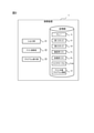
- FIG. 2 is a functional configuration diagram showing the functions of the arithmetic unit 1 as functional blocks. However, FIG. 2 also shows the information stored in the storage unit 5.
- the arithmetic unit 1 includes an input / output unit 21, a test arithmetic unit 22, and a program execution unit 23 as its functions.
- the storage unit 5 stores the queue Q, the first stack S1, the second stack S2, the confirmed list CL, the processed list PL, the area table T100, and the test target program information TP.
- the queue Q, the first stack S1, the second stack S2, the confirmed list CL, and the processed list PL are objects to be read / written by the test calculation unit 22, and the data used by the test calculation unit 22 in the process of processing is stored. The place. In this embodiment, these information are not output to the outside of the arithmetic unit 1.
- the queue Q is a general queue used in the field of programming, and has the property that the first input data is output first.
- the first stack S1 and the second stack S2 are general stacks used in the field of programs, and have the property that the first input data is output last.
- the confirmed list CL and the processed list PL are a set of elements, and there is no order between the elements.
- the queue Q, the first stack S1, and the second stack S2 describe their elements in the order in which they are input. For example, when the first stack S1 is empty, that is, an empty set, when first "A", then "B", and finally "C" are input to the first stack S1, that is, pushed, the first stack is pushed.
- the data of S1 is described as "A, B, C".
- the test target program information TP is information related to the target program to be tested by the arithmetic unit 1.
- program P1 the program to be tested by the arithmetic unit 1
- the test target program information TP includes at least information that can create a program P1, such as a source code and an object file.
- the operation of the program P1 can be expressed using a non-circulating directed graph.
- the non-circular directed graph showing the operation of the program P1 may be included in the test target program information TP, or may be created by the arithmetic unit 1 using a known method such as disassembly.
- the area table T100 stores information obtained by analyzing the program P1 by the test calculation unit 22. Details will be described later.
- the input / output unit 21 acquires information necessary for the calculation from the outside of the arithmetic unit 1, for example, information about the program P1 and an operator's instruction, and outputs the calculation result to the outside of the arithmetic unit 1 as needed.
- the input / output unit 21 is realized by using the external interface 6 in addition to the calculation by the CPU 2.
- the test calculation unit 22 performs various calculations necessary for testing the program P1.
- the operation of the test calculation unit 22 will be mainly described.
- the test calculation unit 22 executes a structural analysis process for analyzing the structure of the program P1 to be processed.
- the program P1 is divided into a non-parallel group that does not contribute to parallelization and a parallel contribution group that contributes to parallelization.
- the second stack S2 for specifying the parallel contribution group is created among the macro tasks constituting the program P1. That is, among the macro tasks constituting the program P1, the macro tasks not specified by the second stack S2 are non-parallel groups.
- the test calculation unit 22 performs a table creation process in which the information of each area included in the program P1 is put together in the area table T100 by using the result of the structural analysis process. Further, the test calculation unit 22 performs a memory dump process for acquiring a memory dump for an efficient test. Finally, the test calculation unit 22 executes a program test for a predetermined area. The order of execution of the table creation process and the memory dump process does not matter.
- the program execution unit 23 executes the program P1 according to the operation command of the test calculation unit 22. However, the program execution unit 23 may execute the entire program P1, or may execute only a part of the program P1. Further, the program execution unit 23 has a function of stopping the execution of the program at a position designated by the test calculation unit 22. Further, the program execution unit 23 may emulate a processor built in the computer that executes the program P1 by software, or the arithmetic unit 1 has a processor different from the CPU 2, and the program execution unit 23 is the same. A processor may be used.
- the program P1 can be decomposed into a plurality of processing units, and its operation is represented by a non-circulated directed graph. That is, the arithmetic unit 1 can analyze any program as long as it can express the operation using the non-circulated directed graph.
- each processing unit will be referred to as a "macro task".
- a macro task is one or more processes that do not include branch processing internally.
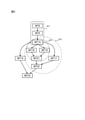
- FIG. 3 is a directed graph showing the program P1 to be processed in the present embodiment.
- the program P1 is composed of a total of 10 macro tasks of MT6, MT9, MT14, MT16, MT17, MT18, MT19, MT21, MT22, and MT23.
- the positional relationship of the macro task shown in FIG. 3 is also related to the direction of the arrows, and each arrow is directed from the upper part of the figure to the lower part of the figure, and is also said to be from the ancestor to the descendant. That is, the more it is described in the upper part of the figure, the more it is an ancestor, and the more it is described in the lower part of the figure, the more it is a descendant.
- FIG. 3 shows that when MT14 is completed, MT16 to MT19 are executed in no particular order.
- the first ancestor in a predetermined range is also referred to as a "root node”
- the last descendant in a predetermined range is referred to as a "terminal node”.
- the root node is MT6 and the terminal node is MT23.
- Area A11 surrounded by a rectangle in FIG. 3 includes MT6, MT9, and MT14.
- the area A12 surrounded by the broken line includes MT14, MT18, MT19 and MT21.
- the area A13 surrounded by the alternate long and short dash line includes MT14, MT17 to MT19, MT21, and MT22.
- the root node is MT6 and the terminal node is MT14.
- the root node is MT14 and the terminal node is MT21.
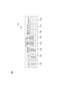
- FIG. 4 is a diagram showing an example of the area table T100. Information on the parallel contribution group calculated by the test calculation unit 22 is described in the area table T100. As will be described in detail later, the parallel contribution group calculated in the area table T100 differs depending on the task of interest to be set.
- the example shown in FIG. 4 is an example in which the program P1 shown in FIG. 3 is targeted and the task of interest is T22. Note that FIG. 4 conceptually represents the area table T100 only in a tabular format, and it is not necessary to record the area table T100 in a tabular format. In each cell of the table, a link to the actual state of the data may be described. good.
- the area table T100 has one or more records, and each record has a program T101, an area ID T102, a parallelized binary T103, a start task T104, an end task T105, a start point dump T106, an end point dump T107, and a directed graph T108.
- the program T101 stores an identifier of the program to be analyzed, for example, the name of the program.
- the area ID T102 stores an area identifier, for example, an area name.
- the parallelized binary T103 is a binary file that executes the processing included in the area of the record, and stores the binary file that has been parallelized as much as possible. That is, if parallelization processing is possible in the area, the binary file that has been parallelized is stored, and if parallelization processing is not possible in the area, the non-parallelized binary file is stored. ..
- the start task T104 stores the name of the most ancestral macro task included in the area of the record.
- the end task T105 stores the name of the most descendant macro task included in the area of the record.
- the start point dump T106 stores the dump information of the memory in the last processing of the start task T104.
- the memory dump information is also called a "memory snapshot”.
- the end point dump T107 stores the dump information of the memory in the first processing of the end task T105.
- the directed graph T108 stores information on the directed graph of the macro task included in the area of the record, for example, the directed graph shown in FIG.
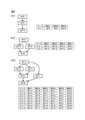
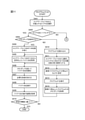
- FIG. 5 is a diagram showing test cases corresponding to each area shown in FIG.
- the test case is created by the test calculation unit 22.
- the test case is a list in which all the macro tasks contained in the area are arranged in the order of execution, and the example shown in FIG. 5 lists all the possible execution orders.
- the test case of the area A11 is not created in this embodiment, it is described in FIG. 5 for reference.
- Area A11 contains three macro tasks, which are connected in a straight line in series. That is, in the area A11, there is no choice in the execution order of the macro tasks, and there is only one case "A11-1". Since each task in area A11 needs to be executed in order, it is a non-parallel group that does not contribute to parallelization.
- Area A12 contains four macro tasks, and MT18 and MT19 exist in parallel. Therefore, since either MT18 or MT19 may be executed first, there are two cases of area A12, "A12-1" and "A12-2". Specifically, the first execution is fixed at MT14, the last execution is fixed at MT21, and the second and third macro tasks to be executed are either MT18 or MT19.
- Area A13 includes 6 macro tasks, and a first group of MT18, MT19, and MT21 and a second group consisting of only MT17 exist in parallel. Further, inside the first group, MT18 and MT19 exist in parallel. Macro tasks that exist in parallel can be executed at any timing regardless of the execution order. Therefore, in the area A13, there are eight cases of "A13-1" to "A13-8".
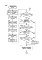
- step S100 the test calculation unit 22 initializes the queue Q, the first stack S1, the second stack S2, and the confirmed list CL. Specifically, by the initialization process of this step, the queue Q, the first stack S1, the second stack S2, and the confirmed list CL are set to the empty set, that is, the empty set.
- step S101 the test calculation unit 22 reads various information about the program P1.
- step S102 the test calculation unit 22 extracts the directed graph D1 from the information read in the step S101.
- the directed graph D1 extracted in this step is an effective graph exemplified in FIG.
- the test calculation unit 22 determines the point of interest X, which is one of the macro task MTs included in the program P1.
- the point of interest X may be automatically selected by machine processing, for example, where an error was found by the previous execution, or may be set manually by the operator. In the description of the operation example in this flowchart, the point of interest X is "MT22".
- the test calculation unit 22 creates an ancestor list C1 of the attention point X.
- the directed graph D1 is shown in FIG. 3, and when the point of interest X is “MT22”, the ancestor list C1 becomes “MT6, MT9, MT14, MT17, MT18, M19, MT21”.
- step S105 the test calculation unit 22 sets the point of interest X as the processing target Xi.
- step S106 the test calculation unit 22 sets the processing target Xi to confirmed. Specifically, the test calculation unit 22 adds "MT22", which is the processing target Xi, to the confirmed list CL.
- step S106A the test calculation unit 22 proceeds to step S106A.
- step S106A the test calculation unit 22 determines whether or not an unconfirmed adjacent node of the processing target Xi exists in the ancestor list C1.
- Adjacent nodes are nodes that are only one apart, regardless of their descendants or ancestors, in other words, regardless of their vertical position. For example, in the example shown in FIG. 3, the adjacent node of "MT22" is "MT17, MT21, MT23".
- test calculation unit 22 determines that there is an unconfirmed adjacent node of the processing target Xi in the ancestor list C1
- the process proceeds to step S107, and all the adjacent nodes of the processing target Xi included in the ancestor list C1 have been confirmed. If it is determined, the process proceeds to step S107A.
- the test calculation unit 22 can first list all the adjacent nodes of the processing target Xi included in the ancestor list C1 and determine this step depending on whether or not they are listed in the confirmed list CL.
- step S107 the test calculation unit 22 determines whether or not the input degree of the processing target Xi is larger than 1.
- the test calculation unit 22 proceeds to step S110 when it is determined that the input order of the processing target Xi is larger than 1, and step S107A when it is determined that the input order of the processing target Xi is not larger than 1, that is, 1 or less. Proceed to.
- step S107A the test calculation unit 22 determines whether or not there is an adjacent node of the confirmed processing target Xi in the ancestor list C1. Comparing the judgment in this step with step S106A, it is different whether it is unconfirmed or confirmed.
- the process proceeds to step S108, and all the adjacent nodes of the processing target Xi included in the ancestor list C1 are unconfirmed. If it is determined, the process proceeds to step S109.
- step S108 the test calculation unit 22 determines whether or not the degree of the processing target Xi is greater than 1.
- the test calculation unit 22 proceeds to step S110 when it is determined that the degree of the processing target Xi is larger than 1, and proceeds to step S109 when it is determined that the degree of the processing target Xi is 1 or less.
- the input degree of TM14 is “1” and the output degree is “4”.
- step S109 the test calculation unit 22 determines whether or not the processing target Xi corresponds to the source node XN in the ancestor list C1.
- the test calculation unit 22 proceeds to step S110 if it determines that the processing target Xi corresponds to the source node XN in the ancestor list C1, and step S111 if it determines that the processing target Xi does not correspond to the source node XN in the ancestor list C1. Proceed to.
- step S111 the test calculation unit 22 extracts the neighboring nodes of the processing target Xi and defines the adjacent group N. For example, in the example shown in FIG. 3, when the processing target Xi is “MT22”, the adjacent group N is “MT17, MT21, MT23”.
- step S111A in FIG. 7 via the circled A. The above is the explanation of FIG.
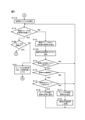
- step S111A of FIG. 7 the test calculation unit 22 initializes the processed list PL.
- step S119 the test calculation unit 22 determines whether or not all the elements of the adjacent group N have been processed, and if it is determined that all the elements have been processed, proceeds to step S120 and determines that there are unprocessed elements. In that case, the process proceeds to step S112.
- step S119 the test calculation unit 22 can determine step S119 by comparing the element of the adjacent group N with the macro task described in the processed list PL.
- step S112 the test calculation unit 22 extracts any unprocessed macro task as an element Ni from the adjacent group N.
- step S112A the test calculation unit 22 adds the element Ni extracted in step S112 to the processed list PL.
- the test calculation unit 22 adds the name of the macro task extracted as the element Ni in step S112 to the processed list PL.
- step S113 the test calculation unit 22 determines whether or not the element Ni is included in the ancestor list C1. The test calculation unit 22 proceeds to step S114 when it is determined that the element Ni is included in the ancestor list C1, and returns to step S119 when it is determined that the element Ni is not included in the ancestor list C1.
- step S114 the test calculation unit 22 determines whether or not the element Ni has been confirmed, in other words, whether or not the element Ni is listed in the confirmed list CL.
- the test calculation unit 22 proceeds to step S115 if it determines that the element Ni has been confirmed, and proceeds to step S117 if it determines that the element Ni has not been confirmed.
- step S115 the test calculation unit 22 determines whether or not the element Ni is included in the queue Q.
- the test calculation unit 22 proceeds to step S116 when it is determined that the element Ni is included in the queue Q, and returns to step S119 when it is determined that the element Ni is not included in the queue Q.
- step S117 the test calculation unit 22 adds the element Ni to the end of the queue Q.
- step S118 the test calculation unit 22 changes the element Ni to confirmed. Specifically, the test calculation unit 22 adds the name of the macro task extracted as the element Ni to the confirmed list CL.
- step S120 which is executed when a positive judgment is made in step S119, the test calculation unit 22 determines whether or not the queue Q is an empty set.
- the test calculation unit 22 determines that the queue Q is an empty set, it proceeds to step S601 in FIG. 8 via the encircled C, and when it determines that the queue Q is not an empty set, it proceeds to step S121.
- the case where the affirmative determination is made in step S120 is the case where step S117 is not executed even once before step S120 is executed.
- step S121 the test calculation unit 22 takes out the head of the queue Q, sets it as the processing target Xi, and returns to step S106A in FIG. 6 via the circled B.
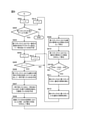
- step S601 which is the first process shown in FIG. 8, the test calculation unit 22 substitutes zero for the variable i and proceeds to step S602.
- step S602 the test calculation unit 22 determines whether or not the length of the first stack S1 is longer than the value of “i + 1”.
- the length of the first stack S1 is the number of macro tasks added to the first stack S1.
- step S603 determines that the length of the first stack S1 is equal to or less than the value of "i + 1". If so, the process shown in FIG. 8 is terminated.
- step S603 the test calculation unit 22 extracts the i + 1st element in the first stack S1 from the directed graph D1 and creates an ancestor list of the extracted macro task as a temporary ancestor list A00.
- the element number of the first stack S1 defines the last added element as the “0” th element. If elements are added to the first stack S1 in the order of "MT22, MT21, MT14" and the value of the variable i is zero, the "i + 1" th element of the first stack S1 is "MT21". .. ⁇ Ask in the comments whether it is correct> The ancestor list of this "MT21" is created as a temporary ancestor list A00.
- the temporary ancestor list A00 in this case is "MT14, MT18, M19".
- the temporary ancestor list A00 created in step S603 has an expiration date until the next time step S603 is executed or the process of FIG. 8 is completed, whichever is earlier.
- step S604 the test calculation unit 22 assigns the value of the variable i to the variable j and proceeds to step S605.
- step S605 the test calculation unit 22 determines whether or not the value of the variable j is larger than "-1", and if it is determined that the variable j is larger than "-1", proceeds to step S606 and proceeds to the variable j. If it is determined that is "-1" or less, the process proceeds to step S614.
- step S606 the test calculation unit 22 identifies the macro task which is the jth element in the first stack S1, extracts the descendants of the macro task from the ancestor list C1, and creates the temporary descendant list D00.
- the temporary descendant list D00 is "MT17, MT18, MT19, MT21".
- the test calculation unit 22 extracts the elements common to the temporary descendant list D00 created in step S606 and the temporary ancestor list A00 created in step S603, and creates a duplicate list IS00. For example, when the temporary descendant list D00 is "MT17, MT18, MT19, MT21" and the temporary ancestor list A00 is "MT14, MT18, M19", the duplicate list IS00 is "MT18, M19".
- the test calculation unit 22 calculates a value obtained by subtracting the output degree from the input degree in each element of the duplicate list IS00, and calculates the total as SD00.
- step S609 the test calculation unit 22 calculates the degree of the jth element in the macro task in the first stack S1 as OD00.
- step S610 the test calculation unit 22 calculates the input degree in the macro task of the jth element in the first stack S1 as ID00.
- step S610 the test calculation unit 22 uses the calculation results of steps S608 to S610 to determine whether or not the value obtained by subtracting ID00 from the sum of OD00 and SD00 is zero or more.
- the test calculation unit 22 proceeds to step S611 when making an affirmative determination in step S610, and proceeds to step S613 when making a negative determination.
- step S611 the test calculation unit 22 inserts the i + 1th element of the first stack S1 into the second stack S2.
- step S612 the test calculation unit 22 inserts the j-th element of the first stack S1 into the second stack S2 and proceeds to step S614.
- steps S611 and S612 are so-called push operations for the second stack S2.
- step S613 the test calculation unit 22 reduces the value of the variable j by "1" and returns to step S605.
- step S614 the test calculation unit 22 increases the value of the variable i by "1" and returns to step S602.
- Step S613 is a so-called decrement process
- step S614 is a so-called increment process.
- first stack S1 generated by the processes of FIGS. 6 to 8 includes information indicating an area including a branch.
- the second stack S2 includes information indicating an area including a branch in the area included in the first stack S1.
- step S102 An operation example of the structural analysis process will be described. In the operation example described below, the description of the operation main body is omitted, but the operation main body is all the test calculation unit 22.
- the directed graph D1 extracted in step S102 is shown in FIG. 3, and an example in the case where the point of interest X is “MT22” will be described.
- the ancestor list C1 generated in step S104 is "MT6, MT9, MT14, MT17, MT18, MT19, MT21".
- step S106A the test calculation unit 22 makes an affirmative judgment because the adjacent node of "MT22", which is the processing target Xi, exists in the ancestor list C1 and is not included in the confirmed list CL. Since the input order of "MT22" is 2 in step S107, the test calculation unit 22 makes an affirmative judgment and proceeds to step S110, and the first stack S1 is updated to "MT22".
- step S111 the test calculation unit 22 defines the adjacent group N as "MT17, MT21, MT23".
- the processing of S113 to S118 is performed with all the elements included in the adjacent group N as elements Ni in order.
- step S113 is determined affirmatively, step S114 is determined negatively, steps S117 and S118 are executed, and the process returns to step S119.
- step S113 is determined affirmatively, step S114 is determined negatively, steps S117 and S118 are executed, and the process returns to step S119.
- step S113 is negatively determined and the process returns to step S119.
- step S119 when making an affirmative judgment in step S119 for the first time, the queue Q is "MT17, MT21", the confirmed list CL is “MT17, MT21, MT22", and the first stack S1 is "MT22".
- step S120 the test calculation unit 22 makes a negative judgment, proceeds to step S121, extracts the head "MT17” from the queue Q, sets it as the processing target Xi, and returns to step S106A in FIG. 6 via the encircled B. .. That is, when returning to S106A, the element of the queue Q is only "MT21".
- steps S106A and S107A are positively determined, but since the input and output degrees of "MT17” are "1", steps S107 and S108 are negatively determined. Further, since "MT17” is not a source node in the ancestor list C1, the process proceeds to step S111.
- "MT14, MT22" in the vicinity of "MT17” is defined as a new adjacent group N, and the process proceeds to FIG. 7.
- step S113 is determined affirmatively, step S114 is determined negatively, steps S117 and S118 are executed, and the process returns to step S119.
- step S113 is positively determined, and step S114 is positively determined because of the processing in step S106. Since "MT22" is not included in the queue Q, it is negatively determined and the process returns to step S119.
- step S119 makes a positive judgment for the second time, the queue Q is "MT21, MT14", the confirmed list CL is "MT17, MT21, MT22, MT14", and the first stack S1 is "MT22". Since the queue Q is not an empty set here as well, the process proceeds from step S120 to step S121, the first “MT21” is taken out from the queue Q, and the process returns to step S106A in FIG. That is, when returning to S106A, the element of the queue Q is only "MT14".
- step S106A is affirmatively determined, and since the input degree of "MT21” is "2", step S107 is affirmatively determined, the process proceeds to S110, and "MT21" is added to the first stack S1. .. That is, the first stack S1 becomes "MT22, MT21".
- step S111 "MT18, MT19, MT22" in the vicinity of "MT21” is defined as a new adjacent group N, and the process proceeds to FIG. 7.
- step S113 is determined affirmatively, step S114 is determined negatively, steps S117 and S118 are executed, and the process returns to step S119.
- step S113 is determined affirmatively, step S114 is determined negatively, steps S117 and S118 are executed, and the process returns to step S119.
- step S113 is determined affirmatively, step S114 is determined affirmatively, and "MT22" is not included in the queue Q, so a negative determination is made and the process returns to step S119.
- step S119 makes a positive judgment for the third time, the queue Q is "MT14, MT18, MT19", the confirmed list CL is "MT17, MT18, MT19, MT21, MT22, MT14", and the first stack S1 is. It is "MT22, MT21". Since the queue Q is not an empty set here as well, the process proceeds from step S120 to step S121, the first “MT14” is taken out from the queue Q, and the process returns to step S106A in FIG. That is, when returning to S106A, the elements of the queue Q become "MT18, MT19".
- step S106A is negatively determined and S107A is affirmative. .. Since the degree of "MT14" is larger than 1, step S108 is positively determined, the process proceeds to S110, and "MT14" is added to the first stack S1. That is, the first stack S1 becomes "MT22, MT21, MT14".
- step S111 "MT9, MT16, MT17, MT18, MT19" in the vicinity of "MT14" is defined as a new adjacent group N, and the process proceeds to FIG.
- steps S113 to S118 are performed with each of the elements of the adjacent group N "MT9, MT16, MT17, MT18, MT19" as the element Ni.
- step S113 is negatively determined and the process returns to step S119.
- step S113 is positively determined, "MT17” is confirmed, so step S114 is positively determined, and "MT17” is not included in the queue Q, so it is negatively determined and the process is set to S119.
- steps S113, S114, and S119 are positively determined, and the element Ni is added to the end of the queue Q in step S116. That is, at this point, the queue Q is "MT18, MT19", and the first stack S1 is "MT22, MT21, MT14". Since the queue Q is not an empty set here as well, the process proceeds from step S120 to step S121, the first “MT18” is taken out from the queue Q, and the process returns to step S106A in FIG. That is, when returning to S106A, the element of the queue Q becomes "MT19".
- step S106A is negatively determined and S107A is affirmative.
- step S108 since the degree of "MT14" is "1”, a negative determination is made and the process proceeds to S109. Since "MT14" is not a source node, a negative determination is made and the process proceeds to step S111.
- step S111 "MT14, MT21" in the vicinity of "MT19" is defined as a new adjacent group N, and the process proceeds to FIG. 7.
- steps S113 to S118 are performed with each of the elements “MT14, MT21” of the adjacent group N as the element Ni.
- step S113 is positively judged because it is included in the ancestor list C1
- step S114 is positively judged because it is included in the confirmed list CL, and it is not included in the queue Q. Therefore, a negative judgment is made and the process returns to step S119. Then, in step S119, an affirmative judgment is made.
- step S120 since the queue Q is not an empty set, the process proceeds to step S121, the first "MT19" is taken out from the queue Q, and the process returns to step S106A in FIG. That is, when returning to S106A, the elements of the queue Q become an empty set.
- step S106A is negatively determined and S107A is affirmative.
- step S108 since the degree of "MT14" is "1”, a negative determination is made and the process proceeds to S109. Since "MT19" is not a source node, a negative determination is made and the process proceeds to step S111.
- step S111 "MT14, MT21" in the vicinity of "MT19” is defined as a new adjacent group N, and the process proceeds to FIG. 7.
- steps S113 to S118 are performed with each of the elements “MT14, MT21” of the adjacent group N as the element Ni.
- step S113 is positively judged because it is included in the ancestor list C1
- step S114 is positively judged because it is included in the confirmed list CL, and it is not included in the queue Q. Therefore, a negative judgment is made and the process returns to step S119. Then, in step S119, an affirmative judgment is made.
- step S120 since the queue Q is an empty set, an affirmative judgment is made for the first time, and the process proceeds to step S601 in FIG. 8 via the encircled C.
- the first stack S1 is "MT22, MT21, MT14".
- step S602 since the length of the first stack S1 is "3", it is larger than "i + 1", that is, "1", so that a positive judgment is made. Since the "i + 1", that is, the "1st” th element in the first stack S1 is "MT21”, in step S603, the ancestor list "MT14, MT18, MT19" of "MT21” is set as the temporary ancestor list A00. In the following S604, zero, which is the value of the variable i, is assigned to the variable j, and in the following step S605, since the variable j is larger than "-1", an affirmative judgment is made and the process proceeds to step S606.
- step S606 the descendants of "MT14", which is the "j" th element, that is, the "0" th element of the first stack S1, are extracted from the ancestor list C1, and "MT18, MT19, MT21" are set as the temporary descendant list D00. ..
- step S607 "MT18, MT19" common to the temporary descendant list D00 and the temporary ancestor list A00 is set as the duplicate list IS00.
- step S608 SD00 is set to zero, which is the sum of the differences between the input and output degrees of MT18 and MT19.
- step S609 the degree "4" of "MT14", which is the "j" th element, that is, the "0" th element of the first stack S1, is set to OD00.
- step S610 the input degree "2" of "MT21", which is the “i + 1" th element of the first stack S1, that is, the "1” th element, is set to ID00.
- step S610A the value of OD00 + SD00-ID00 is calculated as "2", and since this is zero or more, an affirmative judgment is made and the process proceeds to step S611.
- step S611 the "i + 1" th element of the first stack S1, that is, the “1st” th element “MT21” is inserted into the second stack S2.
- step S612 the "j" th element, that is, the "0" th element of the first stack S1 "MT14” is inserted into the second stack S2.
- step S614 the variable i is incremented to "1” and the process returns to step S602.
- the second stack S2 was updated to "MT21, MT14" by the process of the first week of FIG. 8 described above.
- step S602 executed for the second time, since the length "3" of the first stack S1 is longer than "i + 1", that is, "2”, an affirmative judgment is made and the process proceeds to S603.
- step S603 "MT14, MT17, MT18, MT19, MT21", which is the ancestor list of "MT22" which is the "i + 1" th element of the first stack S1, that is, the "2" th element, is set as the temporary ancestor list A00.
- the value "1" of the variable i is assigned to the variable j, and in the following step S605, since the variable j is larger than "-1", an affirmative judgment is made and the process proceeds to step S606.
- step S606 since the descendants of "MT21", which is the "j" th element of the first stack S1, that is, the "1" th element, do not exist in the ancestor list C1, the temporary descendant list D00 is an empty set. Therefore, the duplicate list IS00 in step S607 is also an empty set, and SD00 is zero.
- step S609 the degree "1" of "MT21", which is the "j" th element of the first stack S1, that is, the "1" th element, is set to OD00.
- step S610 the input degree "2" of the "MT22" which is the “i + 1" th element, that is, the "2" th element of the first stack S1 is set to ID00.
- step S610A the value of OD00 + SD00-ID00 is calculated as "-1", and since this is less than zero, a negative determination is made and the process proceeds to step S613.
- step S613 the variable j is decremented and updated from "1" to "0". Then, the process returns to step S605. In the process of the second week of FIG. 8 described above, there is no change in the second stack S2.
- step S605 which is the third execution, the value of the variable j is zero and is larger than "-1", so an affirmative judgment is made and the process proceeds to step S606.
- step S606 the descendants of "MT14", which is the "j" th element, that is, the "0" th element of the first stack S1, are extracted from the ancestor list C1, and "MT18, MT19, MT21" are set as the temporary descendant list D00. ..
- step S607 "MT18, MT19" common to the temporary descendant list D00 and the temporary ancestor list A00 is set as the duplicate list IS00.
- step S608 SD00 is set to zero, which is the sum of the differences between the input and output degrees of MT18 and MT19.
- step S609 the degree "4" of "MT14", which is the "j" th element, that is, the "0" th element of the first stack S1, is set to OD00.
- step S610 the input degree "2" of the "MT22" which is the “i + 1" th element, that is, the "2" th element of the first stack S1 is set to ID00.
- step S610A the value of OD00 + SD00-ID00 is calculated as "2", and since this is zero or more, an affirmative judgment is made and the process proceeds to step S611.
- step S611 the "i + 1" th element, that is, the "2" th element of the first stack S1 "MT22” is inserted into the second stack S2.
- step S612 the "j" th element, that is, the "0" th element of the first stack S1 "MT14” is inserted into the second stack S2.
- step S614 the variable i is incremented to "2” and the process returns to step S602.
- the second stack S2 was updated to "MT21, MT14, MT22, MT14" by the process of the third week of FIG. 8 described above.
- step S602 since the length "3" of the first stack S1 is not longer than "i + 1", that is, "3”, a negative determination is made and the structural analysis process is terminated.
- "MT21, MT14, MT22, MT14" is obtained as the second stack S2.
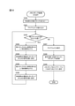
- FIG. 9 is a flowchart showing a table creation process by the test calculation unit 22.
- the table creation process can be executed as long as the structural analysis process is completed, and it does not matter before and after the memory dump process and the execution. However, the table creation process must be completed before the program test.
- the test calculation unit 22 copies the second stack S2 created by the structural analysis processing shown in FIGS. 6 to 8 in step S200.
- a pop operation is performed on the second stack S2 to change the second stack S2. Therefore, the copied second stack is copied so that this does not affect other processes such as the memory dump process.
- S2 is used in the following processing.
- the test calculation unit 22 performs parallel processing of steps S201 to S203. However, it is not essential that steps S201 to S203 are processed in parallel, and three may be processed in order.
- step S201 the test calculation unit 22 reads the program P1.
- step S202 the test calculation unit 22 acquires the directed graph D1 of the program P1.
- step S203 the test calculation unit 22 creates an ancestor list C1 of the attention point X.
- the point of interest X in step S203 is the point of interest X determined in step S103 of the structural analysis process.
- the test calculation unit 22 proceeds to step S204 when all the executions of steps S201 to S203 are completed.
- step S204 the test calculation unit 22 determines whether or not the length of the second stack S2 is longer than 2. When the test calculation unit 22 determines that the length of the second stack S2 is 2 or more, it proceeds to step S205, and when it determines that the length of the second stack S2 is less than 2, the process shown in FIG. 9 ends.
- step S205 the test calculation unit 22 performs pop processing on the second stack S2, and names the acquired TM as the first element G.
- step S205 the test calculation unit 22 performs pop processing again on the second stack S2, and names the acquired TM as the second element H. That is, two elements are deleted from the second stack S2 by the processing of steps S205 and S206.
- step S207 the test calculation unit 22 applies the parallelization algorithm to the first element G to the second element H of the program P1. There are no restrictions on the parallelization algorithm applied in this step, and various known algorithms can be applied.
- the test calculation unit 22 creates a partial ancestor list PDi from the first element G to the second element H based on the ancestor list C1. That is, the range from the first element G to the second element H in the ancestor list C1 is named the partial ancestor list PDi.
- the test calculation unit 22 generates a parallelized binary Bi from the first element G to the second element H of the program P1.
- the test calculation unit 22 saves the partial ancestor list PDi created in step S208 in the T108 column of the area table T100, and saves the binary Bi created in step S209 in the T103 column of the area table T100.
- the test calculation unit 22 stores the first element G to the second element H as the area Ai in the column of T102 of the area table T100.
- step S211 the test calculation unit 22 records the first instruction of the second element H in the column of T105 of the area table T100.
- step S212 the test calculation unit 22 records the last instruction of the first element G in the column of T104 of the area table T100, and returns to step S204. Since the execution order of the macro task changes depending on the situation between the two instructions recorded here, the macro task is repeatedly executed in the later test. Therefore, steps S211 to S212 are executed in order to record the start point and the end point to be repeatedly executed. In the second stack S2, the number of elements decreases by 2 each time the processes of steps S205 to S212 are performed, and when the length of the second stack S2 becomes less than 2, the process of FIG. 9 ends.
- the last instruction of the second element H may be recorded in step S211 or the first instruction of the first element G may be recorded in step S212.
- the order of processing inside the first element G and the second element H is fixed, repeating execution up to a place where the order is fixed deteriorates the efficiency of the test. Therefore, as described in the flowchart, it is desirable to record the last instruction of the first element G and record the first instruction of the second element H.
- step S200 the second stack S2 in which the four "MT21, MT14, MT22, MT14" are stored in order from the beginning is copied.
- steps S201 to S202 will be omitted.
- step S203 since the point of interest X is “MT22” as in the above-mentioned operation example, the created ancestor list C1 is “MT6, MT9, MT14, MT17, MT18, MT19, MT21” as in the above.
- step S204 since the length of the second stack S2 is "4", it is judged affirmatively because it is 2 or more. Then, in step S205, the last input "MT14" is popped to be the first element G, and in step S206, "MT22" is popped to be the second element H. By the first processing of steps S205 to S206, the length of the second stack S2 is changed from "4" to "2".
- step S207 the parallelization algorithm is applied to MT14 to MT22, and in step S208, the partial ancestor list PDi of MT14 to MT22 is created.
- the partial ancestor list PDi may include information on a directed graph that is schematized so that it can be easily understood by humans, or information on a directed graph that is logically described so that it can be easily processed by a computer. good.
- step S209 a parallelized binary Bi of MT14 to MT22 is created.
- step S210 the partial ancestor list PDi and the binary Bi are stored in the area table T100.
- step S210A new area IDs are attached to MT14 to MT22 and stored in the first record of the area table T100.
- step S211 the first instruction of MT22 and the last instruction of MT14 in the following step S212 are stored in the first record of the area table T100.
- step S204 the length of the second stack S2 is "2", so a positive judgment is made and the process proceeds to step S205.
- step S205 "MT14" is set to the first element G
- step S206 "MT21” is set to the second element H.
- the length of the second stack S2 is changed from “2" to "0”.
- steps S207 to S212 writing is performed on the second row of the area table T100 for "MT14" to "MT21". Individual explanations will be omitted.
- FIG. 10 is a flowchart showing a memory dump process by the test calculation unit 22.
- the memory dump process can be executed as long as the structural analysis process is completed, and it does not matter before and after the table creation process and execution. However, the memory dump process needs to be executed before the program test.
- step S300 the test calculation unit 22 copies the second stack S2 created by the structural analysis process.
- a pop operation is performed on the second stack S2 to change the second stack S2. Therefore, the copy is made so that this does not affect other processes such as the table creation process.
- 2 Stack S2 is used in the following processing.
- step S301 the test calculation unit 22 reads the program P1 and proceeds to step S302.
- step S302 the test calculation unit 22 determines whether or not the length of the second stack S2 is longer than 2.
- the test calculation unit 22 determines that the length of the second stack S2 is 2 or more, it proceeds to step S303, and when it determines that the length of the second stack S2 is less than 2, it proceeds to step S307.
- step S303 the test calculation unit 22 performs pop processing on the second stack S2, and names the acquired macro task as the third element M.
- step S304 the test calculation unit 22 sets the end of the third element M to the signal position for the memory dump.
- step S305 the test calculation unit 22 performs pop processing again on the second stack S2, and names the acquired TM as the fourth element N.
- step S306 the test calculation unit 22 sets the beginning of the TM of the fourth element N to the signal position for the memory dump, and returns to the step S302. That is, two elements are deleted from the second stack S2 by the processing of steps S303 and S305.
- step S307 the test calculation unit 22 executes the program P1. Then, in step S308, the test calculation unit 22 acquires a memory dump each time the program P1 reaches the signal position set in steps S304 and S306. In the following step S309, the test calculation unit 22 saves the memory dump acquired in step S308 in the columns of T106 and T107 of the area table, and ends the process shown in FIG. Specifically, the memory dump acquired at the signal position corresponding to step S304 is recorded in T106, and the memory dump acquired at the signal position corresponding to step S306 is recorded in T107.
- step S300 the second stack S2 in which the four "MT21, MT14, MT22, MT14" are stored in order from the beginning is copied.
- step S301 the program P1 is read.
- step S302 since the length of the second stack S2 is "4", it is judged affirmatively because it is 2 or more. Then, in step S303, the last input "MT14" is popped to be the third element M, and in step S304, the last instruction of "MT14" is set at the signal position. In step S305, “MT22” is popped to be the fourth element N, and in step S306, the first instruction of "MT22" is set to the signal position. By the processing of the first steps S303 and S305, the length of the second stack S2 is changed from "4" to "2".
- step S302 since the length of the second stack S2 is "2", it is judged affirmatively because it is 2 or more. Then, in step S303, "MT14" is popped to be the third element M, and in step S304, the last command of "MT14" is set at the signal position. In step S305, “MT21” is popped to be the fourth element N, and in step S306, the first instruction of "MT21” is set to the signal position. By the processing of the first steps S303 and S305, the length of the second stack S2 is changed from “2" to "0".
- step S307 the program P1 is executed, and in step S308, a memory dump, in other words, a snapshot of the memory is acquired every time the signal position is reached. Then, in step S309, the acquired memory dump is saved in the area table T100, and the memory dump process is terminated.
- FIG. 11 is a flowchart showing a program test by the test calculation unit 22.
- the test calculation unit 22 first selects the target area Ai from the area table T100 in step S401. This selection may be made based on manual operation by the operator, or may be selected by automatic processing according to a predetermined rule.
- the automatic processing according to a predetermined rule is, for example, to select the area Ai listed in the area table T100 one by one in order from the top.
- step S402 the test calculation unit 22 determines whether or not to heat run the area Ai selected in step S401. If the test calculation unit 22 determines that the heat run is to be performed, the process proceeds to step S403, and if it is determined that the heat run is not to be performed, the test calculation unit 22 proceeds to S501 of FIG. 12 via the circled D. The determination in step S402 is made based on, for example, a preset setting by the operator. In step S403, the test calculation unit 22 determines whether or not to use the memory dump. The test calculation unit 22 proceeds to step S404 when it is determined to use the memory dump, and proceeds to step S410 when it is determined not to use the memory dump. The determination in step S403 is made based on, for example, a preset setting by the operator.
- step S404 the test calculation unit 22 reads the T106 column of the area table T100 and proceeds to step S405.
- step S405 the test calculation unit 22 acquires the parallelized binary Bi from the column of T103 of the area table T100 and proceeds to step S406.
- step S406 the test calculation unit 22 initializes the parallelized binary Bi by using the memory dump.
- step S407 the test calculation unit 22 makes necessary modifications to the state of the parallelized binary Bi, in other words, the information stored in the memory. This modification is for making the execution result of the binary Bi reach a predetermined threshold value, for example, rewriting the value of a specific variable.
- step S408 the test calculation unit 22 executes the parallelized binary Bi, and in the following step S409, the test calculation unit 22 acquires the execution result of the parallelized binary Bi.
- step S410 the test calculation unit 22 determines whether or not the execution result of the parallelized binary Bi has reached a predetermined threshold value. The test calculation unit 22 ends the process shown in FIG. 11 when it is determined that the predetermined threshold has been reached, and returns to step S406 when it is determined that the predetermined threshold has not been reached.
- step S410 which is executed when a negative determination is made in step S403, the test calculation unit 22 reads the program P1.
- the test calculation unit 22 reads the column of T104 corresponding to the area Ai selected from the area table T100, and hereinafter, the macro task described in this column is referred to as a loop start element F.
- step S412 the test calculation unit 22 sets the program P1 to stop at the loop start element F.
- step S413 the test calculation unit 22 executes the program P1.
- step S414 the test calculation unit 22 acquires a memory dump of the program P1 stopped at the loop start element F and proceeds to step S405.
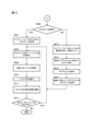
- FIG. 12 is a flowchart showing a process to be executed when a negative determination is made in step S402 in FIG.
- step S501 which is executed when a negative determination is made in step S402
- the test calculation unit 22 reads the information in the column of T108 of the area table T100.
- step S502 the test calculation unit 22 reads an additional request regarding the directed graph by the operator.
- step S503 the test calculation unit 22 processes the directed graph in response to the additional request read in step S502.
- the first specific example in steps S502 to S503 is that the execution order of macro tasks is specified, and more specifically, it is limited to the execution order in which "MT17" is executed third.
- the second specific example is to add a macro task specified by the operator to a specified position.
- test calculation unit 22 extracts all the routes from the directed graph D1 processed in the step S503.
- test calculation unit 22 creates a binary PBi corresponding to each path, and proceeds to FIG. 13 via the circled E.
- FIG. 13 is a flowchart showing a process executed after step S505 in FIG.
- step S506 which is executed after step S505
- the test calculation unit 22 determines whether or not to use the memory dump.
- the test calculation unit 22 proceeds to step S507 when it is determined to use the memory dump, and proceeds to step S513 when it is determined not to use the memory dump.
- step S507 the test calculation unit 22 acquires a memory dump from the T106 column of the area table T100 and proceeds to step S508.
- step S508 the test calculation unit 22 initializes the binary PBi using the memory dump acquired in step S507.
- step S509 the test calculation unit 22 operates the input as necessary. This operation is, for example, rewriting the value in memory.
- step S510 the test calculation unit 22 executes the binary PBI.
- the test calculation unit 22 confirms the execution result of the binary PBI executed in step S510.
- step S512 the test calculation unit 22 determines whether or not the binary PBI to be executed still exists.
- the test calculation unit 22 returns to step S508 when it is determined that the binary PBI to be executed still exists, and ends the process shown in FIG. 13 when it is determined that the binary PBI to be executed does not exist.
- step S513 which is executed when a negative determination is made in step S506, the test calculation unit 22 reads the macro task described in the column of T104 in the area table T100 and sets it as element E.
- step S514 the test calculation unit 22 sets the program P1 to stop at the element E.
- step S515 the test calculation unit 22 executes the program P1.
- step S516 the test calculation unit 22 acquires a memory dump of the program P1 stopped in the element E, and proceeds to step S508. The above is the process of FIG.
- Program test operation example The following describes a plurality of operation examples of the program test. However, in the following, only the outline of the operation will be explained, and the detailed explanation will be omitted. Further, the presence / absence of a heat run and the presence / absence of a memory dump are instructed in advance by the operator for each operation example. In the operation example described below, the description of the operation main body is omitted, but the operation main body is all the test calculation unit 22.
- program test operation example 1 An operation example 1 of the program test will be described.
- the heat run is not performed and the memory dump is not used.
- a negative determination is made in step S402, and the process proceeds to step S501 in FIG. 12 via the circled D.
- steps S501 to S505 are executed, and the process proceeds to step S506 in FIG. 13 via the encircled E. Since the memory dump is not used in step S506, a negative determination is made and the process proceeds to step S513.
- steps S513 to S516 the column of the start task T104 of the area table T100 is set as the reading element F, and the memory dump when the program P1 reaches the element F is acquired.
- steps S508 to S511 the binary PBi is initialized and executed using the memory dump acquired in S516.
- the binary PBi to be executed is created in steps S504 to S505 corresponding to all the paths of the directed graph, and the processes of steps S508 to S511 are repeated until all of them are executed.
- Step S506 Operation example 2 of the program test will be described.
- a memory dump is used without performing a heat run. Since operation example 2 is the same as operation example 1 until it reaches FIG. 13, the description of the processing up to step S506 will be omitted. Since a memory dump is used in step S506, an affirmative judgment is made, and in step S507, a memory dump is acquired from the column of the start point dump T106 of the area table T100. Since the processing after step S508 is the same as the operation example 1, the description thereof will be omitted.
- step S403 A third operation example of the program test will be described.
- a heat run is performed and a memory dump is not used.
- step S402 since the heat run is performed, a positive judgment is made in step S402, and since the memory dump is not used, a negative judgment is made in step S403 and the process proceeds to step S410.
- steps S410 to S414 the program P1 is read, the column of the start task T104 of the area table T100 is read, and the memory dump when the program P1 reaches the element F is acquired as the element F.
- steps S405 to S06 the parallelized binary Bi is acquired from the area table T100, and the binary Bi is initialized by using the memory dump.
- step S407 the binary Bi is executed after making necessary modifications, and the modifications in S407 are repeatedly executed while changing the modifications until the execution result reaches a desired threshold value. Then, when the desired threshold value is reached, the test is terminated.
- program test operation example 4 A fourth operation example of the program test will be described.
- a heat run is performed and a memory dump is used.
- step S402 since the heat run is performed, a positive judgment is made in step S402
- step S403 since the memory dump is used, a positive judgment is made in step S403 and the process proceeds to step S404.
- step S404 the memory dump is read from the area table T100 and the process proceeds to step S405. Since the processing after step S405 is the same as that of the operation example 3, the description thereof will be omitted.
- the test method executed by the arithmetic unit 1 is a test method in which the arithmetic unit 1 which is a computer tests a program including a plurality of macro tasks which may be executed in a plurality of orders. This method sets one of a plurality of macro tasks as a point of interest (S103 in FIG. 6) and identifies an ancestor list C1 which is a set of macro tasks that affect the point of interest X (FIG. 6).
- the result obtained by executing the macro task belonging to the non-parallel group is a dump of the memory of the computer that executes the macro task, and a plurality of test patterns are executed using one dump (Fig.). 11 S410: NO loop, S512: YES loop in FIG. 13). Therefore, since the memory dump is used instead of executing the same process many times, the time for executing a plurality of test patterns can be shortened.
- the test method executed by the arithmetic unit 1 includes modifying the generated test pattern based on the operator's command (S502 to S503 in FIG. 12). Therefore, not only the automatically generated test pattern but also the corrections that the operator is interested in can be arbitrarily added.
- the configuration of the functional block is only an example.
- Several functional configurations shown as separate functional blocks may be integrally configured, or the configuration represented by one functional block diagram may be divided into two or more functions. Further, a configuration in which a part of the functions of each functional block is provided in another functional block may be provided.
- the program executed by the arithmetic unit 1 is stored in the ROM 3, but the program may be stored in the storage unit 5. Further, the arithmetic unit may read a program from another device when necessary via a medium in which the external interface 6 can be used.
- the medium refers to, for example, a storage medium that can be attached to and detached from an input / output interface, or a communication medium, that is, a network such as a wired, wireless, or optical network, or a carrier wave or digital signal that propagates in the network.
- some or all of the functions realized by the program may be realized by the hardware circuit or FPGA.
- Arithmetic unit 5 ... Storage unit 21 ... Input / output unit 22 ... Test calculation unit 23 ... Program execution unit D1 ... Directed graph Q ... Queue S1 ... First stack S2 ... Second stack T100 ... Area table
Landscapes
- Engineering & Computer Science (AREA)
- Theoretical Computer Science (AREA)
- Computer Hardware Design (AREA)
- Quality & Reliability (AREA)
- Physics & Mathematics (AREA)
- General Engineering & Computer Science (AREA)
- General Physics & Mathematics (AREA)
- Debugging And Monitoring (AREA)
Abstract
実行される順番が複数とおり存在し得る複数のマクロタスクを含むプログラムをコンピュータがテストするテスト方法であって、複数のマクロタスクのいずれかを注目タスクに設定することと、注目タスクに影響を与えるマクロタスクの集合である先祖リストを特定することと、先祖リストに含まれるマクロタスクを、並列化に寄与しない非並列群および並列化に寄与する並列寄与群に分別することと、並列寄与群についてテストパタンを複数生成することと、非並列群に属するマクロタスクを実行して得られた結果を用いて、複数のテストパタンを実行することと、を含むテスト方法。
Description
本発明は、テスト方法および演算装置に関する。
複雑なプログラムは一般に検証が困難である。ソフトウエアへの要求レベルが高い分野では、単体テストレベルで100%のテストカバレッジを取得する必要がある。プログラム内の処理の順番が常に一定である順次プログラムでは、テスト時に相互依存が問題になることはほとんどなく、テストの困難性は限定的である。その一方で、プログラム内の処理の順番が一定ではない非順次プログラムではテストが困難である。
プログラムの規模が大きいシステムや高速な処理が必要なシステム、たとえば、自動車の高度運転支援システム(ADAS)や自動運転システム(ADS)などのリアルタイムシステムでは、複数のプロセッサが用いられる。また、従来のシングルコア用システムがマルチコアのハードウエア上に構築された場合には、自動並列化処理により複数のシステムを統合することができる。このどちらの場合にも、プログラム内の処理が実行される順番は膨大なため、安全に統合することは容易ではない。従来のシングルコアソフトウェアに対して自動並列化コンパイラを適用すると、並列化されたコードが元のコードと同じ機能と動作を持っていることを実際に確認できるかどうかという別の問題も発生する。
コンパイラにより正しく実行されたことの確認を行うというアイデアは、特にプログラム言語からアセンブリコードへの変換のレベルで開発された。このレベルでは、プログラム依存グラフという名前で有向非巡回グラフを使用することで、バイナリコードの効率化と自動並列化の向上に大きく貢献している。
特許文献1には、複数のテストノード及び該テストノード間のプロセスを定義したテストシナリオに関する情報を記憶するシナリオ情報記憶手段と、テストノードごとに、次に遷移するべきテストノードを識別する情報を含むテストノードに関する情報、プロセスが分岐する分岐パスを含むか否かに関する情報を記憶するテストノード情報記憶手段と、テストノードごとに前記分岐パスが存在するか否かを判断する第一の判断手段と、該第一の判断手段で前記分岐パスが存在すると判断したテストノードにおいて、スナップショットを取得した場合にテストを完了するまでに要する実行予測時間を算出する実行予測時間算出手段と、スナップショットを取得することなくテストを完了するまでに要する実行時間を算出する実行時間算出手段と、スナップショットを取得したテストノードごとに、実行時間と実行予測時間との差分を短縮時間として算出する短縮時間算出手段と、前記短縮時間が最も大きいテストノードを選択する選択手段と、選択したテストノードを識別する情報を出力する出力手段とを備えるテスト支援装置が開示されている。
特許文献1に記載されている発明では、実行される順番が複数とおり存在し得る複数のマクロタスクを含むプログラムのテストにおいて特定のマクロタスクを対象としたテストが効率的に実行できない。
本発明の第1の態様によるテスト方法は、実行される順番が複数とおり存在し得る複数のマクロタスクを含むプログラムをコンピュータがテストするテスト方法であって、前記複数のマクロタスクのいずれかを注目タスクに設定することと、前記注目タスクに影響を与える前記マクロタスクの集合である先祖リストを特定することと、前記先祖リストに含まれる前記マクロタスクを、並列化に寄与しない非並列群および並列化に寄与する並列寄与群に分別することと、前記並列寄与群についてテストパタンを複数生成することと、前記非並列群に属する前記マクロタスクを実行して得られた結果を用いて、前記複数の前記テストパタンを実行することと、を含む。
本発明の第2の態様による演算装置は、実行される順番が複数とおり存在し得る複数のマクロタスクを含むプログラムを格納する記憶部と、前記複数のマクロタスクのいずれかを注目タスクに設定し、前記注目タスクに影響を与える前記マクロタスクの集合である先祖リストを特定し、前記先祖リストに含まれる前記マクロタスクを、並列化に寄与しない非並列群および並列化に寄与する並列寄与群に分別し、前記並列寄与群についてテストパタンを複数生成するテスト演算部と、前記非並列群に属する前記マクロタスクを実行して得られた結果を用いて、前記複数の前記テストパタンを実行するプログラム実行部と、を含む。
本発明の第2の態様による演算装置は、実行される順番が複数とおり存在し得る複数のマクロタスクを含むプログラムを格納する記憶部と、前記複数のマクロタスクのいずれかを注目タスクに設定し、前記注目タスクに影響を与える前記マクロタスクの集合である先祖リストを特定し、前記先祖リストに含まれる前記マクロタスクを、並列化に寄与しない非並列群および並列化に寄与する並列寄与群に分別し、前記並列寄与群についてテストパタンを複数生成するテスト演算部と、前記非並列群に属する前記マクロタスクを実行して得られた結果を用いて、前記複数の前記テストパタンを実行するプログラム実行部と、を含む。
本発明によれば、実行される順番が複数とおり存在し得る複数のマクロタスクを含むプログラムのテストにおいて、特定のマクロタスクを対象としたテストが効率的に実行できる。
―第1の実施の形態―
以下、図1~図13を参照して、演算装置が実行するテスト方法の第1の実施の形態を説明する。
以下、図1~図13を参照して、演算装置が実行するテスト方法の第1の実施の形態を説明する。
(ハードウエア構成)
図1は、本発明に係るテスト方法を実行する演算装置1のハードウエア構成図である。演算装置1は、中央演算装置であるCPU2と、読み出し専用の記憶装置であるROM3と、読み書き可能な記憶装置であるRAM4と、不揮発性の記憶装置である記憶部5と、外部インタフェース6とを備える。CPU2は、ROM3に格納されるプログラムをRAM4に展開して実行することで後述する複数の機能を実現する。記憶部5はたとえば、ハードディスクドライブやフラッシュメモリなどである。ただし記憶部5が演算装置1の内部に格納されることは必須の構成要件ではなく、演算装置1の外部に設置された記憶部5に対して演算装置1が外部インタフェース6を介してアクセスしてもよい。
図1は、本発明に係るテスト方法を実行する演算装置1のハードウエア構成図である。演算装置1は、中央演算装置であるCPU2と、読み出し専用の記憶装置であるROM3と、読み書き可能な記憶装置であるRAM4と、不揮発性の記憶装置である記憶部5と、外部インタフェース6とを備える。CPU2は、ROM3に格納されるプログラムをRAM4に展開して実行することで後述する複数の機能を実現する。記憶部5はたとえば、ハードディスクドライブやフラッシュメモリなどである。ただし記憶部5が演算装置1の内部に格納されることは必須の構成要件ではなく、演算装置1の外部に設置された記憶部5に対して演算装置1が外部インタフェース6を介してアクセスしてもよい。
外部インタフェース6は、演算装置1の外部とのインタフェースであり、対象は人間およびコンピュータのいずれでもよい。たとえば、人間を対象とするマウス、キーボード、ディスプレイ、およびプリンタなどの装置そのものやこれら装置の接続インタフェースでもよい。また他のコンピュータを対象とする通信インタフェース、およびリムーバブルメディアの読み書き装置でもよい。以下では、演算装置1を操作する人間を「オペレータ」と呼ぶ。
(機能構成)
図2は、演算装置1が有する機能を機能ブロックとして表した機能構成図である。ただし図2には記憶部5に格納される情報も示している。演算装置1はその機能として、入出力部21と、テスト演算部22と、プログラム実行部23とを備える。記憶部5には、キューQと、第1スタックS1と、第2スタックS2と、確認済リストCLと、処理済リストPLと、エリアテーブルT100と、テスト対象プログラム情報TPとが格納される。
図2は、演算装置1が有する機能を機能ブロックとして表した機能構成図である。ただし図2には記憶部5に格納される情報も示している。演算装置1はその機能として、入出力部21と、テスト演算部22と、プログラム実行部23とを備える。記憶部5には、キューQと、第1スタックS1と、第2スタックS2と、確認済リストCLと、処理済リストPLと、エリアテーブルT100と、テスト対象プログラム情報TPとが格納される。
キューQ、第1スタックS1、第2スタックS2、確認済リストCL、および処理済リストPLは、テスト演算部22が読み書きする対象であり、テスト演算部22が処理の過程で利用するデータの格納場所である。これらの情報は本実施の形態では演算装置1の外部に対して出力されない。キューQは、プログラムの分野で用いられる一般的なキューであり、最初に入力されたデータが最初に出力される性質を有する。第1スタックS1および第2スタックS2は、プログラムの分野で用いられる一般的なスタックであり、最初に入力されたデータが最後に出力される性質を有する。確認済リストCLおよび処理済リストPLは要素の集合であり要素間の順序は存在しない。
本実施の形態では、キューQ、第1スタックS1、および第2スタックS2は、入力された順番にその要素を記載する。たとえば第1スタックS1がカラ、すなわち空集合の状態において、最初に「A」、次に「B」、最後に「C」が第1スタックS1に入力、すなわちプッシュされた場合は、第1スタックS1のデータを「A、B、C」と記載する。
テスト対象プログラム情報TPは、演算装置1がテストを行う対象のプログラムに関する情報である。以下では、演算装置1がテストを行う対象のプログラムを「プログラムP1」と呼ぶ。テスト対象プログラム情報TPには、少なくともプログラムP1を作成可能な情報、たとえばソースコードやオブジェクトファイルが含まれる。なお後述するように、プログラムP1の動作は非循環有向グラフを用いて表現ができる。プログラムP1の動作を示す非循環有向グラフは、テスト対象プログラム情報TPに含まれてもよいし、逆アセンブルなどの既知の手法を用いて演算装置1が作成してもよい。エリアテーブルT100には、テスト演算部22がプログラムP1を解析して得られた情報が格納される。詳しくは後述する。
入出力部21は、演算装置1の外部から演算に必要な情報、たとえばプログラムP1に関する情報やオペレータの指示を取得し、必要に応じて演算装置1の外部に演算結果を出力する。入出力部21は、CPU2による演算に加えて、外部インタフェース6をあわせて用いることで実現される。
テスト演算部22は、プログラムP1のテストを行うために必要な様々な演算を行う。以下では主にテスト演算部22の動作を説明する。テスト演算部22は初めに、処理対象であるプログラムP1の構造を解析する構造解析処理を実行する。構造解析処理ではプログラムP1を、並列化に寄与しない非並列群および並列化に寄与する並列寄与群に分別する。ただし厳密には構造解析処理では、プログラムP1を構成するマクロタスクのうち、並列寄与群を特定する第2スタックS2を作成する。すなわちプログラムP1を構成するマクロタスクのうち第2スタックS2により特定されないマクロタスクが非並列群である。
構造解析処理の次にテスト演算部22は、構造解析処理の結果を利用してプログラムP1に含まれる各エリアの情報をエリアテーブルT100にまとめるテーブル作成処理を行う。さらにテスト演算部22は、効率的なテストのためにメモリダンプを取得するメモリダンプ処理を行う。最後にテスト演算部22は、所定のエリアを対象としてプログラムテストを実行する。なおテーブル作成処理とメモリダンプ処理は実行の順番は不問である。
プログラム実行部23は、テスト演算部22の動作指令に従い、プログラムP1を実行する。ただしプログラム実行部23は、プログラムP1の全体を実行する場合もあるが、プログラムP1の一部だけを実行する場合もある。さらにプログラム実行部23は、テスト演算部22により指定された位置でプログラムの実行を停止する機能を有する。またプログラム実行部23は、プログラムP1を実行するコンピュータに内蔵されるプロセッサをソフトウエアでエミュレートしてもよいし、CPU2とは異なるプロセッサを演算装置1が有しておりプログラム実行部23はそのプロセッサを利用してもよい。
(プログラムの例示)
プログラムP1は、複数の処理単位に分解可能であり、非巡回有向グラフによりその動作が表される。すなわち演算装置1は、非巡回有向グラフを用いて動作が表現できるプログラムであれば、あらゆるプログラムを分析対象とできる。以下では処理単位のそれぞれを「マクロタスク」と呼ぶ。マクロタスクは、内部に分岐処理を含まない1または複数の処理である。
プログラムP1は、複数の処理単位に分解可能であり、非巡回有向グラフによりその動作が表される。すなわち演算装置1は、非巡回有向グラフを用いて動作が表現できるプログラムであれば、あらゆるプログラムを分析対象とできる。以下では処理単位のそれぞれを「マクロタスク」と呼ぶ。マクロタスクは、内部に分岐処理を含まない1または複数の処理である。
図3は、本実施の形態において処理対象とするプログラムP1を示す有向グラフである。プログラムP1は、MT6、MT9、MT14、MT16、MT17、MT18、MT19、MT21、MT22、およびMT23の合計10のマクロタスクにより構成される。図3に示すマクロタスクの位置関係は、矢印の向きとも関係があり、いずれの矢印も図示上部から図示下部に向かっており、先祖から子孫に向かうとも言う。すなわち、図示上部に記載されているほど先祖であり、図示下部に記載されているほど子孫である。
プログラムP1の処理が開始すると最初の先祖であるMT14の実行が開始され、最後の子孫であるMT23の実行が完了するとプログラムP1が終了する。図3は、MT14が完了すると、順不同でMT16~MT19がそれぞれ実行されることを示している。以下では、所定の範囲における最初の先祖を「ルートノード」とも呼び、所定の範囲における最後の子孫を「末端ノード」と呼ぶ。たとえば図3に示す全体の範囲ではルートノードはMT6であり、末端ノードはMT23である。
図3において矩形で囲むエリアA11は、MT6、MT9、およびMT14を含む。破線で囲むエリアA12は、MT14、MT18、MT19およびMT21を含む。一点鎖線で囲むエリアA13は、MT14、MT17~MT19、MT21、およびMT22を含む。エリアA11において、ルートノードはMT6、末端ノードはMT14である。エリアA12において、ルートノードはMT14、末端ノードはMT21である。
(エリアテーブルT100)
図4は、エリアテーブルT100の一例を示す図である。エリアテーブルT100には、テスト演算部22が算出した並列寄与群の情報が記載される。詳しくは後述するが、エリアテーブルT100に算出される並列寄与群は、設定される注目タスクにより異なる。図4に示す例は、図3に示したプログラムP1を対象とし、注目タスクをT22とした場合の例である。なお図4は概念的にエリアテーブルT100を表形式で表現しているにすぎず、表形式で記録しなくてもよいし、表の各セルにはデータの実態へのリンクを記載してもよい。
図4は、エリアテーブルT100の一例を示す図である。エリアテーブルT100には、テスト演算部22が算出した並列寄与群の情報が記載される。詳しくは後述するが、エリアテーブルT100に算出される並列寄与群は、設定される注目タスクにより異なる。図4に示す例は、図3に示したプログラムP1を対象とし、注目タスクをT22とした場合の例である。なお図4は概念的にエリアテーブルT100を表形式で表現しているにすぎず、表形式で記録しなくてもよいし、表の各セルにはデータの実態へのリンクを記載してもよい。
エリアテーブルT100は1または複数のレコードを有し、各レコードはプログラムT101、エリアID T102、並列化済バイナリT103、開始タスクT104、終了タスクT105、開始点ダンプT106、終了点ダンプT107、および有向グラフT108のフィールドを有する。プログラムT101には、解析対象となるプログラムの識別子、たとえばプログラムの名称が格納される。エリアID T102には、エリアの識別子、たとえばエリアの名称が格納される。
並列化済バイナリT103には、そのレコードのエリアに含まれる処理を実行するバイナリファイルであって、可能な限り並列化処理が施されたバイナリファイルが格納される。すなわちそのエリアにおいて並列化処理が可能な場合には並列化処理が施されたバイナリファイルが格納され、そのエリアにおいて並列化処理が不可能な場合には並列化されていないバイナリファイルが格納される。
開始タスクT104には、そのレコードのエリアに含まれる最も先祖のマクロタスクの名称が格納される。終了タスクT105には、そのレコードのエリアに含まれる最も子孫のマクロタスクの名称が格納される。開始点ダンプT106には、開始タスクT104の最後の処理におけるメモリのダンプ情報が格納される。なおメモリのダンプ情報は、「メモリのスナップショット」とも呼ばれる。
終了点ダンプT107には、終了タスクT105の最初の処理におけるメモリのダンプ情報が格納される。有向グラフT108には、そのレコードのエリアに含まれるマクロタスクの有向グラフ、たとえば図3に示す有向グラフの情報が格納される。
(テストケース)
図5は、図3に示す各エリアに対応するテストケースを示す図である。テストケースは、テスト演算部22により作成される。テストケースは、エリア内に含まれるすべてのマクロタスクを実行順に並べたリストであり、図5に示す例では実現可能なすべての実行順番を列挙している。なお本実施の形態ではエリアA11のテストケースは作成されないが、図5では参考のために記載している。エリアA11は3つのマクロタスクが含まれ、それらは直列に一直線で接続される。すなわちエリアA11ではマクロタスクの実行順番は選択の余地がなくケース「A11-1」の1とおりのみが存在する。エリアA11の各タスクは、順番に実行する必要があるので、並列化に寄与しない非並列群である。
図5は、図3に示す各エリアに対応するテストケースを示す図である。テストケースは、テスト演算部22により作成される。テストケースは、エリア内に含まれるすべてのマクロタスクを実行順に並べたリストであり、図5に示す例では実現可能なすべての実行順番を列挙している。なお本実施の形態ではエリアA11のテストケースは作成されないが、図5では参考のために記載している。エリアA11は3つのマクロタスクが含まれ、それらは直列に一直線で接続される。すなわちエリアA11ではマクロタスクの実行順番は選択の余地がなくケース「A11-1」の1とおりのみが存在する。エリアA11の各タスクは、順番に実行する必要があるので、並列化に寄与しない非並列群である。
エリアA12は4つのマクロタスクが含まれ、MT18とMT19が並列に存在する。そのため、MT18とMT19のいずれが先に実行される場合もありえるため、エリアA12は「A12-1」および「A12-2」の2つのケースが存在する。具体的には、最初に実行されるのはMT14で固定、最後に実行されるのはMT21で固定であり、2番目と3番目に実行されるマクロタスクがMT18およびMT19のいずれかである。
エリアA13は、6つのマクロタスクが含まれ、大きくはMT18、MT19、およびMT21の第1グループと、MT17のみからなる第2のグループが並列に存在する。さらに第1のグループの内部ではMT18とMT19が並列に存在する。並列に存在するマクロタスクは実行順番が不問であり、いずれのタイミングで実行されてもよい。そのためエリアA13では「A13-1」~「A13-8」の8つのケースが存在する。
(構造解析処理のフローチャート)
図6~図8は、テスト演算部22による構造解析処理を示すフローチャートである。まずステップS100ではテスト演算部22は、キューQ、第1スタックS1、第2スタックS2、および確認済リストCLを初期化する。具体的には本ステップの初期化処理により、キューQ、第1スタックS1、第2スタックS2、および確認済リストCLがカラ、すなわち空集合に設定される。
図6~図8は、テスト演算部22による構造解析処理を示すフローチャートである。まずステップS100ではテスト演算部22は、キューQ、第1スタックS1、第2スタックS2、および確認済リストCLを初期化する。具体的には本ステップの初期化処理により、キューQ、第1スタックS1、第2スタックS2、および確認済リストCLがカラ、すなわち空集合に設定される。
続くステップS101ではテスト演算部22は、プログラムP1に関する各種情報を読み込む。続くステップS102ではテスト演算部22は、ステップS101において読み込んだ情報から有向グラフD1を抽出する。本フローチャートにおける動作例の説明において、本ステップにおいて抽出した有向グラフD1は、図3に例示した有効グラフとする。
続くステップS103ではテスト演算部22は、プログラムP1に含まれるいずれかのマクロタスクMTである注目点Xを決定する。注目点Xは、機械処理によりたとえば直前の実行によりエラーが発見された箇所が自動的に選択されてもよいし、オペレータにより手動で設定されてもよい。本フローチャートにおける動作例の説明において、注目点Xは「MT22」とする。続くステップS104ではテスト演算部22は、注目点Xの先祖リストC1を作成する。有向グラフD1が図3に示すもので、注目点Xが「MT22」の場合に先祖リストC1は「MT6,MT9、MT14、MT17、MT18、M19、MT21」となる。
続くステップS105ではテスト演算部22は、注目点Xを処理対象Xiに設定する。続くステップS106ではテスト演算部22は、処理対象Xiを確認済みに設定する。具体的にはテスト演算部22は、処理対象Xiである「MT22」を確認済リストCLに追加する。ステップS106の処理が完了するとテスト演算部22は、ステップS106Aに進む。
ステップS106Aではテスト演算部22は、先祖リストC1中に未確認の処理対象Xiの隣接ノードが存在するか否かを判断する。隣接ノードとは、子孫や先祖に関係なく、換言すると上下方向の位置に関係なく、1つだけ離れたノードである。たとえば図3に示す例において、「MT22」の隣接ノードは「MT17、MT21、MT23」である。
テスト演算部22は、先祖リストC1中に未確認の処理対象Xiの隣接ノードが存在すると判断する場合にはステップS107に進み、先祖リストC1に含まれる処理対象Xiの隣接ノードは全て確認済であると判断する場合にはステップS107Aに進む。具体的にはテスト演算部22は、まず先祖リストC1に含まれる処理対象Xiの隣接ノードを全て挙げ、それらが確認済リストCLに記載されているか否かにより本ステップの判断ができる。
ステップS107ではテスト演算部22は、処理対象Xiの入次数が1より大きいであるか否かを判断する。テスト演算部22は、処理対象Xiの入次数が1より大きいと判断する場合はステップS110に進み、処理対象Xiの入次数が1より大きくない、すなわち1以下であると判断する場合はステップS107Aに進む。
ステップS107Aではテスト演算部22は、先祖リストC1中に確認済の処理対象Xiの隣接ノードが存在するか否かを判断する。本ステップにおける判断をステップS106Aと比較すると、未確認か確認済かが異なる。テスト演算部22は、先祖リストC1中に確認済の処理対象Xiの隣接ノードが存在すると判断する場合にはステップS108に進み、先祖リストC1に含まれる処理対象Xiの隣接ノードは全て未確認であると判断する場合にはステップS109に進む。
ステップS108ではテスト演算部22は、処理対象Xiの出次数が1より大きいか否かを判断する。テスト演算部22は、処理対象Xiの出次数が1より大きいと判断する場合はステップS110に進み、処理対象Xiの出次数が1以下と判断する場合はステップS109に進む。入次数および出次数の具体例を挙げると、図3に示す例においてTM14の入次数は「1」、出次数は「4」である。
ステップS109ではテスト演算部22は、処理対象Xiは先祖リストC1におけるソースノードXNに該当するか否かを判断する。テスト演算部22は、処理対象Xiは先祖リストC1におけるソースノードXNに該当すると判断する場合はステップS110に進み、処理対象Xiは先祖リストC1におけるソースノードXNに該当しないと判断する場合はステップS111に進む。ステップS111ではテスト演算部22は、処理対象Xiの近傍ノードを抽出し、隣接グループNを定義する。たとえば図3に示す例において処理対象Xiが「MT22」の場合は隣接グループNは、「MT17、MT21、MT23」である。ステップS111の処理が完了するとテスト演算部22は、丸囲みのAを経由して図7におけるステップS111Aに進む。以上が図6の説明である。
図7のステップS111Aではテスト演算部22は、処理済リストPLを初期化する。続くステップS119ではテスト演算部22は、隣接グループNの全要素を処理したか否かを判断し、全要素を処理したと判断する場合はステップS120に進み、未処理の要素が存在すると判断する場合はステップS112に進む。ステップS119ではテスト演算部22は、隣接グループNの要素と、処理済リストPLに記載されたマクロタスクとを比較することでステップS119の判断ができる。
ステップS112ではテスト演算部22は、隣接グループNから未処理のいずれかのマクロタスクを要素Niとして抽出する。続くステップS112Aではテスト演算部22は、ステップS112において抽出した要素Niを処理済リストPLに追加する。換言するとテスト演算部22は、ステップS112において要素Niとして抽出されたマクロタスクの名称を処理済リストPLに追加する。続くステップS113ではテスト演算部22は、要素Niが先祖リストC1に含まれるか否かを判断する。テスト演算部22は、要素Niが先祖リストC1に含まれると判断する場合はステップS114に進み、要素Niが先祖リストC1に含まれないと判断する場合はステップS119に戻る。
ステップS114ではテスト演算部22は、要素Niは確認済みであるか否か、換言すると要素Niが確認済リストCLに記載されているか否かを判断する。テスト演算部22は、要素Niは確認済みであると判断する場合はステップS115に進み、要素Niは確認済みではないと判断する場合はステップS117に進む。ステップS115ではテスト演算部22は、要素NiはキューQに含まれるか否かを判断する。テスト演算部22は、要素NiはキューQに含まれると判断する場合はステップS116に進み、要素NiはキューQに含まれないと判断する場合はステップS119に戻る。
ステップS117ではテスト演算部22は、キューQの末尾に要素Niを追加する。続くステップS118ではテスト演算部22は、要素Niを確認済みに変更する。具体的にはテスト演算部22は、要素Niとして抽出されたマクロタスクの名称を確認済リストCLに追加する。
ステップS119において肯定判断されると実行されるステップS120ではテスト演算部22は、キューQが空集合であるか否かを判断する。テスト演算部22は、キューQが空集合であると判断する場合は丸囲みのCを経由して図8のステップS601に進み、キューQが空集合ではないと判断するとステップS121に進む。なおステップS120において肯定判断される場合とは、ステップS120が実行される前にステップS117が1回も実行されない場合である。ステップS121ではテスト演算部22は、キューQの先頭を取り出して処理対象Xiとし、丸囲みのBを経由して図6におけるステップS106Aに戻る。以上が図7の説明である。
図8に示す最初の処理であるステップS601ではテスト演算部22は、変数iにゼロを代入してステップS602に進む。ステップS602ではテスト演算部22は、第1スタックS1の長さが「i+1」の値よりも長いか否かを判断する。なお第1スタックS1の長さとは、第1スタックS1に追加されたマクロタスクの数である。テスト演算部22は、第1スタックS1の長さが「i+1」の値よりも長いと判断する場合はステップS603に進み、第1スタックS1の長さが「i+1」の値以下であると判断する場合は図8に示す処理を終了する。
ステップS603ではテスト演算部22は、第1スタックS1におけるi+1番目の要素を有向グラフD1から抽出し、抽出したマクロタスクの先祖リストを一時先祖リストA00として作成する。前述のとおり本実施の形態では、第1スタックS1の要素番号は、最後に追加された要素を「0」番目として定義する。仮に第1スタックS1に、「MT22,MT21,MT14」の順番に要素が追加され、変数iの値がゼロの場合には、第1スタックS1の「i+1」番目の要素は「MT21」である。<正しいかをコメントで聞く>この「MT21」の先祖リストが一時先祖リストA00として作成される。この場合の一時先祖リストA00は「MT14、MT18、M19」である。なおステップS603において作成される一時先祖リストA00有効期限は、次にステップS603が実行されるとき、および図8の処理が終了するとき、のいずれか早い方までである。
続くステップS604ではテスト演算部22は、変数jに変数iの値を代入してステップS605に進む。ステップS605ではテスト演算部22は、変数jの値が「-1」よりも大きいか否かを判断し、変数jが「-1」よりも大きいと判断する場合はステップS606に進み、変数jが「-1」以下であると判断する場合はステップS614に進む。ステップS606ではテスト演算部22は、第1スタックS1におけるj番目の要素であるマクロタスクを特定し、そのマクロタスクの子孫を先祖リストC1から抽出して一時子孫リストD00を作成する。たとえば第1スタックS1におけるj番目の要素が「MT14」であり、先祖リストC1が「MT14、MT17、MT18、M19、MT21」の場合に一時子孫リストD00は「MT17,MT18,MT19,MT21」となる。
続くステップS607ではテスト演算部22は、ステップS606において作成した一時子孫リストD00と、ステップS603において作成した一時先祖リストA00と共通する要素を抽出して重複リストIS00を作成する。たとえば一時子孫リストD00が「MT17,MT18,MT19,MT21」、一時先祖リストA00が「MT14、MT18、M19」の場合に、重複リストIS00は「MT18、M19」である。続くステップS608ではテスト演算部22は、重複リストIS00の各要素において、入次数から出次数を引いた値を算出してその総和をSD00として算出する。
続くステップS609ではテスト演算部22は、第1スタックS1におけるj番目の要素のマクロタスクにおける出次数をOD00として算出する。続くステップS610ではテスト演算部22は、第1スタックS1におけるj番目の要素のマクロタスクにおける入次数をID00として算出する。続くステップS610ではテスト演算部22は、ステップS608~S610の算出結果を用いて、OD00とSD00の和からID00を引いた値がゼロ以上であるか否かを判断する。テスト演算部22は、ステップS610を肯定判断する場合はステップS611に進み、否定判断する場合はステップS613に進む。
ステップS611ではテスト演算部22は、第2スタックS2に第1スタックS1のi+1番目の要素を挿入する。続くステップS612ではテスト演算部22は、第2スタックS2に第1スタックS1のj番目の要素を挿入してステップS614に進む。なおステップS611およびS612は、第2スタックS2に対するいわゆるプッシュ操作である。ステップS613ではテスト演算部22は、変数jの値を「1」だけ減少させてステップS605に戻る。ステップS614ではテスト演算部22は、変数iの値を「1」だけ増加させてステップS602に戻る。ステップS613は、いわゆるデクリメント処理であり、ステップS614は、いわゆるインクリメント処理である。以上が図8の説明である。
なお図6~図8の処理により生成される第1スタックS1には、分岐を含むエリアを示す情報が含まれる。また第2スタックS2には、第1スタックS1に含まれるエリア内における分岐を含むエリアを示す情報が含まれる。
(構造解析処理の動作例)
構造解析処理の動作例を説明する。以下に説明する動作例では動作主体の記載を省略するが、動作主体は全てテスト演算部22である。ステップS102において抽出される有向グラフD1が図3に示すものであり、注目点Xが「MT22」の場合の例を説明する。この場合に、ステップS104において生成される先祖リストC1は「MT6,MT9、MT14、MT17、MT18、MT19、MT21」である。ステップS106Aではテスト演算部22は、処理対象Xiである「MT22」の隣接ノードが先祖リストC1に存在し、かつ確認済リストCLには含まれていないので肯定判断する。そしてステップS107では「MT22」の入り次数が2なので、テスト演算部22は肯定判断してステップS110に進み、第1スタックS1が「MT22」に更新される。
構造解析処理の動作例を説明する。以下に説明する動作例では動作主体の記載を省略するが、動作主体は全てテスト演算部22である。ステップS102において抽出される有向グラフD1が図3に示すものであり、注目点Xが「MT22」の場合の例を説明する。この場合に、ステップS104において生成される先祖リストC1は「MT6,MT9、MT14、MT17、MT18、MT19、MT21」である。ステップS106Aではテスト演算部22は、処理対象Xiである「MT22」の隣接ノードが先祖リストC1に存在し、かつ確認済リストCLには含まれていないので肯定判断する。そしてステップS107では「MT22」の入り次数が2なので、テスト演算部22は肯定判断してステップS110に進み、第1スタックS1が「MT22」に更新される。
そしてステップS111ではテスト演算部22は、隣接グループNを「MT17、MT21、MT23」と定義する。図7では、隣接グループNの全要素を処理するまでS112~S118のループが回り続けるので、隣接グループNに含まれる全要素を順番に要素NiとしてS113~S118の処理が行われる。
要素Niが「MT17」の場合には、ステップS113が肯定判断され、ステップS114が否定判断され、ステップS117およびステップS118が実行されてステップS119に戻る。要素Niが「MT21」の場合には、ステップS113が肯定判断され、ステップS114が否定判断され、ステップS117およびステップS118が実行されてステップS119に戻る。要素Niが「MT23」の場合には、ステップS113が否定判断されてステップS119に戻る。
したがって、初回にステップS119において肯定判断をする際には、キューQは「MT17、MT21」、確認済リストCLは「MT17、MT21、MT22」、第1スタックS1は「MT22」である。続くステップS120ではテスト演算部22は否定判断をしてステップS121に進み、キューQから先頭の「MT17」を取り出して処理対象Xiとして、丸囲みのBを経由して図6のステップS106Aに戻る。すなわちS106Aに戻った時点でキューQの要素は「MT21」のみとなる。
(構造解析処理の動作例|初回にBを経由した後)
処理対象Xiである「MT17」について、ステップS106A、S107Aは肯定判断されるが、「MT17」の入次数および出次数は「1」なのでステップS107,S108は否定判断される。さらに「MT17」は先祖リストC1におけるソースノードではないのでステップS111に進む。ここで「MT17」の近傍である「MT14、MT22」が新たな隣接グループNとして定義されて図7に進む。
処理対象Xiである「MT17」について、ステップS106A、S107Aは肯定判断されるが、「MT17」の入次数および出次数は「1」なのでステップS107,S108は否定判断される。さらに「MT17」は先祖リストC1におけるソースノードではないのでステップS111に進む。ここで「MT17」の近傍である「MT14、MT22」が新たな隣接グループNとして定義されて図7に進む。
図7では、まず隣接グループNの要素である「MT14、MT22」を順番に要素NiとしてS113~S118の処理が行われる。要素Niが「MT14」の場合には、ステップS113が肯定判断され、ステップS114が否定判断され、ステップS117およびステップS118が実行されてステップS119に戻る。要素Niが「MT22」の場合には、ステップS113が肯定判断され、ステップS106における処理が理由でステップS114が肯定判断される。「MT22」はキューQには含まれないので否定判断されてステップS119に戻る。
すなわちステップS119が2回目に肯定判断をする際には、キューQは「MT21、MT14」、確認済リストCLは「MT17、MT21、MT22、MT14」、第1スタックS1は「MT22」である。ここでもキューQは空集合でないのでステップS120からステップS121に進み、キューQから先頭の「MT21」を取り出して処理対象Xiとして図6のステップS106Aに戻る。すなわちS106Aに戻った時点でキューQの要素は「MT14」のみとなる。
(構造解析処理の動作例|2回目にBを経由した後)
処理対象Xiである「MT21」について、ステップS106Aは肯定判断され、「MT21」の入次数が「2」なのでステップS107が肯定判断されてS110に進み第1スタックS1に「MT21」が追加される。すなわち第1スタックS1は「MT22、MT21」となる。続くステップS111では「MT21」の近傍である「MT18、MT19、MT22」が新たな隣接グループNとして定義されて図7に進む。
処理対象Xiである「MT21」について、ステップS106Aは肯定判断され、「MT21」の入次数が「2」なのでステップS107が肯定判断されてS110に進み第1スタックS1に「MT21」が追加される。すなわち第1スタックS1は「MT22、MT21」となる。続くステップS111では「MT21」の近傍である「MT18、MT19、MT22」が新たな隣接グループNとして定義されて図7に進む。
図7では、まず隣接グループNの要素である「MT18、MT19、MT22」のそれぞれを要素NiとしてS113~S118の処理が行われる。要素Niが「MT18」の場合には、ステップS113が肯定判断され、ステップS114が否定判断され、ステップS117およびステップS118が実行されてステップS119に戻る。
要素Niが「MT19」の場合には、ステップS113が肯定判断され、ステップS114が否定判断され、ステップS117およびステップS118が実行されてステップS119に戻る。要素Niが「MT22」の場合には、ステップS113が肯定判断され、ステップS114が肯定判断され、「MT22」がキューQには含まれないので否定判断されてステップS119に戻る。
すなわちステップS119が3回目に肯定判断をする際には、キューQは「MT14、MT18、MT19」、確認済リストCLは「MT17、MT18、MT19、MT21、MT22、MT14」、第1スタックS1は「MT22、MT21」である。ここでもキューQは空集合でないのでステップS120からステップS121に進み、キューQから先頭の「MT14」を取り出して処理対象Xiとして図6のステップS106Aに戻る。すなわちS106Aに戻った時点でキューQの要素は「MT18、MT19」となる。
(構造解析処理の動作例|3回目にBを経由した後)
処理対象Xiである「MT14」について、先祖リストC1に含まれる隣接ノードである「MT17、MT18、MT19」は全て確認済リストCLに含まれるのでステップS106Aは否定判断され、S107Aでは肯定判断される。そして「MT14」の出次数が1より大きいのでステップS108が肯定判断されてS110に進み第1スタックS1に「MT14」が追加される。すなわち第1スタックS1は「MT22、MT21、MT14」となる。続くステップS111では「MT14」の近傍である「MT9、MT16、MT17、MT18、MT19」が新たな隣接グループNとして定義されて図7に進む。
処理対象Xiである「MT14」について、先祖リストC1に含まれる隣接ノードである「MT17、MT18、MT19」は全て確認済リストCLに含まれるのでステップS106Aは否定判断され、S107Aでは肯定判断される。そして「MT14」の出次数が1より大きいのでステップS108が肯定判断されてS110に進み第1スタックS1に「MT14」が追加される。すなわち第1スタックS1は「MT22、MT21、MT14」となる。続くステップS111では「MT14」の近傍である「MT9、MT16、MT17、MT18、MT19」が新たな隣接グループNとして定義されて図7に進む。
図7では、まず隣接グループNの要素である「MT9、MT16、MT17、MT18、MT19」のそれぞれを要素NiとしてステップS113~S118の処理が行われる。要素Niが「MT9、MT16」の場合には、先祖リストC1に含まれないのでステップS113が否定判断されてステップS119に戻る。要素Niが「MT17」の場合には、ステップS113が肯定判断され、「MT17」が確認済みなのでステップS114が肯定判断され、「MT17」はキューQに含まれないので否定判断されてステップS119に戻る。
要素Niが「MT18、M19」の場合にはいずれも、ステップS113、S114、およびS119が肯定判断され、ステップS116においてキューQの末尾に要素Niが追加される。すなわちこの時点でキューQは「MT18、MT19」、第1スタックS1は「MT22、MT21、MT14」である。ここでもキューQは空集合でないのでステップS120からステップS121に進み、キューQから先頭の「MT18」を取り出して処理対象Xiとして図6のステップS106Aに戻る。すなわちS106Aに戻った時点でキューQの要素は「MT19」となる。
(構造解析処理の動作例|4回目にBを経由した後)
処理対象Xiである「MT18」について、隣接ノードである「MT14、MT21」は全て確認済リストCLに含まれるのでステップS106Aは否定判断され、S107Aでは肯定判断される。ステップS108では、「MT14」の出次数は「1」なので否定判断をしてS109に進み、「MT14」はソースノードではないので否定判断してステップS111に進む。ステップS111では「MT19」の近傍である「MT14、MT21」が新たな隣接グループNとして定義されて図7に進む。
処理対象Xiである「MT18」について、隣接ノードである「MT14、MT21」は全て確認済リストCLに含まれるのでステップS106Aは否定判断され、S107Aでは肯定判断される。ステップS108では、「MT14」の出次数は「1」なので否定判断をしてS109に進み、「MT14」はソースノードではないので否定判断してステップS111に進む。ステップS111では「MT19」の近傍である「MT14、MT21」が新たな隣接グループNとして定義されて図7に進む。
図7では、まず隣接グループNの要素である「MT14、MT21」のそれぞれを要素NiとしてステップS113~S118の処理が行われる。要素Niが「MT14、MT21」の場合にはいずれも、先祖リストC1に含まれるのでステップS113が肯定判断され、確認済リストCLに含まれるのでステップS114が肯定判断され、キューQに含まれないので否定判断されてステップS119に戻る。そしてステップS119では肯定判断がされる。
この場合には、キューQには何ら追加がされず、4回目にBを経由した直後の状態である、キューQには「MT19」のみが含まれる状態である。また第1スタックS1は「MT22、MT21、MT14」である。ステップS120では、キューQは空集合でないのでステップS121に進み、キューQから先頭の「MT19」を取り出して処理対象Xiとして図6のステップS106Aに戻る。すなわちS106Aに戻った時点でキューQの要素は空集合となる。
(構造解析処理の動作例|5回目にBを経由した後)
処理対象Xiである「MT19」について、隣接ノードである「MT14、MT21」は全て確認済リストCLに含まれるのでステップS106Aは否定判断され、S107Aでは肯定判断される。ステップS108では、「MT14」の出次数は「1」なので否定判断をしてS109に進み、「MT19」はソースノードではないので否定判断してステップS111に進む。ステップS111では「MT19」の近傍である「MT14、MT21」が新たな隣接グループNとして定義されて図7に進む。
処理対象Xiである「MT19」について、隣接ノードである「MT14、MT21」は全て確認済リストCLに含まれるのでステップS106Aは否定判断され、S107Aでは肯定判断される。ステップS108では、「MT14」の出次数は「1」なので否定判断をしてS109に進み、「MT19」はソースノードではないので否定判断してステップS111に進む。ステップS111では「MT19」の近傍である「MT14、MT21」が新たな隣接グループNとして定義されて図7に進む。
図7では、まず隣接グループNの要素である「MT14、MT21」のそれぞれを要素NiとしてステップS113~S118の処理が行われる。要素Niが「MT14、MT21」の場合にはいずれも、先祖リストC1に含まれるのでステップS113が肯定判断され、確認済リストCLに含まれるのでステップS114が肯定判断され、キューQに含まれないので否定判断されてステップS119に戻る。そしてステップS119では肯定判断がされる。
5回目にBを経由した後の処理では、キューQには何ら追加がされないので、5回目にBを経由した直後の状態と同様に、キューQは空集合である。ステップS120では、キューQは空集合なので初めて肯定判断をして、丸囲みのCを経由して図8のステップS601に進む。この時点で、第1スタックS1は「MT22、MT21、MT14」である。
(構造解析処理の動作例|図8の初回処理)
第2スタックS2は、図6の冒頭において初期化されて以後、ここまで一切の操作が行われていないので、図8の処理が開始される時点では空集合のままである。第1スタックは図6~図7の処理において上述するようにいくつかの要素が追加されている。なお本実施の形態では、第1スタックS1に対するポップ操作は行われず、第1スタックS1の長さが短くなることはない。
第2スタックS2は、図6の冒頭において初期化されて以後、ここまで一切の操作が行われていないので、図8の処理が開始される時点では空集合のままである。第1スタックは図6~図7の処理において上述するようにいくつかの要素が追加されている。なお本実施の形態では、第1スタックS1に対するポップ操作は行われず、第1スタックS1の長さが短くなることはない。
ステップS601において変数iにゼロを代入する。ステップS602では、第1スタックS1の長さは「3」なので、「i+1」すなわち「1」よりも大きいことから肯定判断がされる。第1スタックS1における「i+1」すなわち「1」番目の要素は「MT21」なので、ステップS603では「MT21」の先祖リストである「MT14、MT18、MT19」を一時先祖リストA00とする。続くS604では変数jに変数iの値であるゼロを代入し、続くステップS605では変数jが「-1」よりも大きいことので肯定判断してステップS606に進む。
ステップS606では、第1スタックS1の「j」番目、すなわち「0」番目の要素である「MT14」の子孫を先祖リストC1から抽出し、「MT18、MT19、MT21」を一時子孫リストD00とする。続くステップS607では、一時子孫リストD00と一時先祖リストA00に共通する「MT18、MT19」を重複リストIS00とする。続くステップS608では、MT18およびMT19の入次数と出次数の差の総和であるゼロをSD00とする。
続くステップS609では、第1スタックS1の「j」番目、すなわち「0」番目の要素である「MT14」の出次数「4」をOD00とする。続くステップS610では、第1スタックS1の「i+1」番目、すなわち「1」番目の要素である「MT21」の入次数「2」をID00とする。続くステップS610Aでは、OD00+SD00-ID00の値を「2」と算出し、これがゼロ以上なので肯定判断してステップS611に進む。
ステップS611では、第2スタックS2に第1スタックS1の「i+1」番目、すなわち「1」番目の要素である「MT21」を挿入する。続くステップS612では、第2スタックS2に第1スタックS1の「j」番目、すなわち「0」番目の要素である「MT14」を挿入する。続くステップS614では変数iをインクリメントして「1」としてステップS602に戻る。以上説明した図8の1週目の処理により、第2スタックS2は「MT21、MT14」に更新された。
(構造解析処理の動作例|図8の2週目)
2回目に実行されるステップS602では、第1スタックS1の長さ「3」が「i+1」すなわち「2」よりも長いので肯定判断してS603に進む。ステップS603では、第1スタックS1の「i+1」番目、すなわち「2」番目の要素である「MT22」の先祖リストである「MT14、MT17、MT18、MT19、MT21」を一時先祖リストA00とする。続くS604では変数jに変数iの値である「1」を代入し、続くステップS605では変数jが「-1」よりも大きいので肯定判断してステップS606に進む。
2回目に実行されるステップS602では、第1スタックS1の長さ「3」が「i+1」すなわち「2」よりも長いので肯定判断してS603に進む。ステップS603では、第1スタックS1の「i+1」番目、すなわち「2」番目の要素である「MT22」の先祖リストである「MT14、MT17、MT18、MT19、MT21」を一時先祖リストA00とする。続くS604では変数jに変数iの値である「1」を代入し、続くステップS605では変数jが「-1」よりも大きいので肯定判断してステップS606に進む。
ステップS606では、第1スタックS1の「j」番目、すなわち「1」番目の要素である「MT21」の子孫は先祖リストC1に存在しないので一時子孫リストD00は空集合となる。そのためステップS607における重複リストIS00も空集合となり、SD00はゼロである。
続くステップS609では、第1スタックS1の「j」番目、すなわち「1」番目の要素である「MT21」の出次数「1」をOD00とする。続くステップS610では、第1スタックS1の「i+1」番目、すなわち「2」番目の要素である「MT22」の入次数「2」をID00とする。続くステップS610Aでは、OD00+SD00-ID00の値を「-1」と算出し、これがゼロ未満なので否定判断してステップS613に進む。ステップS613では変数jをデクリメントして「1」から「0」に更新する。そしてステップS605に戻る。以上説明した図8の2週目の処理では、第2スタックS2に変動はない。
(構造解析処理の動作例|図8の3週目)
3回目の実行となるステップS605では、変数jの値がゼロであり「-1」よりも大きいので肯定判断してステップS606に進む。
3回目の実行となるステップS605では、変数jの値がゼロであり「-1」よりも大きいので肯定判断してステップS606に進む。
ステップS606では、第1スタックS1の「j」番目、すなわち「0」番目の要素である「MT14」の子孫を先祖リストC1から抽出し、「MT18、MT19、MT21」を一時子孫リストD00とする。続くステップS607では、一時子孫リストD00と一時先祖リストA00に共通する「MT18、MT19」を重複リストIS00とする。続くステップS608では、MT18およびMT19の入次数と出次数の差の総和であるゼロをSD00とする。
続くステップS609では、第1スタックS1の「j」番目、すなわち「0」番目の要素である「MT14」の出次数「4」をOD00とする。続くステップS610では、第1スタックS1の「i+1」番目、すなわち「2」番目の要素である「MT22」の入次数「2」をID00とする。続くステップS610Aでは、OD00+SD00-ID00の値を「2」と算出し、これがゼロ以上なので肯定判断してステップS611に進む。
ステップS611では、第2スタックS2に第1スタックS1の「i+1」番目、すなわち「2」番目の要素である「MT22」を挿入する。続くステップS612では、第2スタックS2に第1スタックS1の「j」番目、すなわち「0」番目の要素である「MT14」を挿入する。続くステップS614では変数iをインクリメントして「2」としてステップS602に戻る。以上説明した図8の3週目の処理により、第2スタックS2は「MT21、MT14、MT22、MT14」に更新された。
ステップS602では、第1スタックS1の長さ「3」が「i+1」すなわち「3」よりも長くないので、否定判断して構造解析処理を終了する。以上説明した処理により、第2スタックS2として「MT21、MT14、MT22、MT14」が得られる。
(テーブル作成処理のフローチャート)
図9は、テスト演算部22によるテーブル作成処理を示すフローチャートである。テーブル作成処理は、構造解析処理が完了していれば実行可能であり、メモリダンプ処理と実行の前後は不問である。ただしテーブル作成処理は、プログラムテストよりも先に実行が完了している必要がある。
図9は、テスト演算部22によるテーブル作成処理を示すフローチャートである。テーブル作成処理は、構造解析処理が完了していれば実行可能であり、メモリダンプ処理と実行の前後は不問である。ただしテーブル作成処理は、プログラムテストよりも先に実行が完了している必要がある。
図9ではまずテスト演算部22は、ステップS200において図6~図8に示した構造解析処理により作成された第2スタックS2をコピーする。後述するようにテーブル作成処理では第2スタックS2に対してポップ操作を行い第2スタックS2が変化するので、これがメモリダンプ処理などの他の処理に影響を与えないように、コピーした第2スタックS2を以下の処理では用いる。テスト演算部22は、ステップS200の処理が完了するとステップS201~S203を並列処理する。ただしステップS201~S203は並列に処理することは必須ではなく、3つを順番に処理してもよい。
ステップS201ではテスト演算部22は、プログラムP1を読み込む。ステップS202ではテスト演算部22は、プログラムP1の有向グラフD1を取得する。ステップS203ではテスト演算部22は、注目点Xの先祖リストC1を作成する。なおステップS203における注目点Xは、構造解析処理のステップS103において決定された注目点Xである。
テスト演算部22は、ステップS201~S203の全ての実行が完了するとステップS204に進む。ステップS204ではテスト演算部22は、第2スタックS2の長さは2よりも長いか否かを判断する。テスト演算部22は、第2スタックS2の長さが2以上であると判断するとステップS205に進み、第2スタックS2の長さが2未満であると判断すると図9に示す処理を終了する。
ステップS205ではテスト演算部22は、第2スタックS2に対してポップ処理を行い、取得したTMを第1要素Gと名付ける。続くステップS205ではテスト演算部22は、第2スタックS2に対して再度のポップ処理を行い、取得したTMを第2要素Hと名付ける。すなわちステップS205およびS206の処理により第2スタックS2から2つの要素が削除される。続くステップS207ではテスト演算部22は、プログラムP1の第1要素Gから第2要素Hまでを対象にして、並列化アルゴリズムを適用する。本ステップにおいて適用する並列化アルゴリズムに制限はなく、公知の様々なアルゴリズムを適用できる。
続くステップS208ではテスト演算部22は、先祖リストC1に基づき第1要素Gから第2要素Hまでの部分先祖リストPDiを作成する。すなわち先祖リストC1における第1要素Gから第2要素Hまでの範囲を部分先祖リストPDiと名付ける。続くステップS209ではテスト演算部22は、プログラムP1の第1要素Gから第2要素Hまでの並列化されたバイナリBiを生成する。
続くステップS210ではテスト演算部22は、ステップS208において作成した部分先祖リストPDiをエリアテーブルT100のT108の欄に保存し、ステップS209において作成したバイナリBiをエリアテーブルT100のT103の欄に保存する。続くステップS210Aではテスト演算部22は、第1要素Gから第2要素HまでをエリアAiとしてエリアテーブルT100のT102の欄に保存する。
続くステップS211ではテスト演算部22は、エリアテーブルT100のT105の欄に、第2要素Hの最初の命令を記録する。続くステップS212ではテスト演算部22は、エリアテーブルT100のT104の欄に第1要素Gの最後の命令を記録してステップS204に戻る。ここで記録した2つの命令の間は、状況によりマクロタスクの実行順番が入れ替わるので、後のテストでは繰り返し実行を行う。そのため、繰り返し実行すべき始点と終点を記録するためにステップS211~S212が実行される。第2スタックS2は、ステップS205~S212の処理を1回行うごとに要素が2ずつ減少し、第2スタックS2の長さが2未満になると図9の処理が終了する。
なおステップS211において第2要素Hの最後の命令を記録してもよいし、ステップS212において第1要素Gの最初の命令を記録してもよい。ただし第1要素Gおよび第2要素Hの内部における処理の順番は固定なので、順番が固定の箇所まで繰り返し実行することはテストの効率を悪化させる。したがって、フローチャートに記載したように、第1要素Gの最後の命令を記録し、第2要素Hの最初の命令を記録することが望ましい。
(テーブル作成処理の動作例)
上述した構造解析処理の動作例において作成した第2スタックS2を用いるテーブル作成処理の動作例を説明する。以下に説明する動作例では動作主体の記載を省略するが、動作主体は全てテスト演算部22である。ステップS200では、先頭から順番に「MT21、MT14、MT22、MT14」の4つが格納された第2スタックS2をコピーする。ステップS201~S202の説明は省略する。ステップS203では注目点Xが上述した動作例と同様に「MT22」なので、作成される先祖リストC1は上記と同様に「MT6,MT9、MT14、MT17、MT18、MT19、MT21」である。
上述した構造解析処理の動作例において作成した第2スタックS2を用いるテーブル作成処理の動作例を説明する。以下に説明する動作例では動作主体の記載を省略するが、動作主体は全てテスト演算部22である。ステップS200では、先頭から順番に「MT21、MT14、MT22、MT14」の4つが格納された第2スタックS2をコピーする。ステップS201~S202の説明は省略する。ステップS203では注目点Xが上述した動作例と同様に「MT22」なので、作成される先祖リストC1は上記と同様に「MT6,MT9、MT14、MT17、MT18、MT19、MT21」である。
次に実行される1回目のステップS204では、第2スタックS2の長さは「4」なので2以上であることから肯定判断する。そしてステップS205では最後に入力された「MT14」をポップして第1要素Gとし、ステップS206では「MT22」をポップして第2要素Hとする。1回目のステップS205~S206の処理により、第2スタックS2の長さは「4」から「2」になる。
続くステップS207では、MT14~MT22に並列化アルゴリズムを適用し、ステップS208ではMT14~MT22の部分先祖リストPDiを作成する。なお部分先祖リストPDiには、人間が理解しやすいように図式化した有向グラフの情報が含まれてもよいし、コンピュータによる処理が容易なように論理的に記載した有向グラフの情報が含まれてもよい。
続くステップS209ではMT14~MT22の並列化されたバイナリBiを作成する。ステップS210では、部分先祖リストPDiとバイナリBiをエリアテーブルT100に保存する。ステップS210Aでは、MT14~MT22に新たなエリアIDを付してエリアテーブルT100の最初のレコードに保存する。続くステップS211では、MT22の最初の命令を、続くステップS212ではMT14の最後の命令を、エリアテーブルT100の最初のレコードに保存する。
2回目のステップS204では、第2スタックS2の長さは「2」なので肯定判断してステップS205に進む。ステップS205では「MT14」が第1要素Gに設定され、ステップS206では「MT21」が第2要素Hに設定される。1回目のステップS205~S206の処理により、第2スタックS2の長さは「2」から「0」になる。以下のステップS207~S212では「MT14」~「MT21」を対象として、エリアテーブルT100の2行目に書き込みが行われる。個別の説明は省略する。
3回目のステップS204では、第2スタックS2の長さは「0」なので否定判断してテーブル作成処理を終了する。以上がテーブル作成処理の動作例の説明である。
(メモリダンプ処理のフローチャート)
図10は、テスト演算部22によるメモリダンプ処理を示すフローチャートである。メモリダンプ処理は、構造解析処理が完了していれば実行可能であり、テーブル作成処理と実行の前後は不問である。ただしメモリダンプ処理は、プログラムテストよりも先に実行が完了している必要がある。
図10は、テスト演算部22によるメモリダンプ処理を示すフローチャートである。メモリダンプ処理は、構造解析処理が完了していれば実行可能であり、テーブル作成処理と実行の前後は不問である。ただしメモリダンプ処理は、プログラムテストよりも先に実行が完了している必要がある。
図10ではまずステップS300において、テスト演算部22は構造解析処理により作成された第2スタックS2をコピーする。後述するように図10に示す処理では第2スタックS2に対してポップ操作を行い第2スタックS2が変化するので、これがテーブル作成処理などの他の処理に影響を与えないように、コピーした第2スタックS2を以下の処理では用いる。続くステップS301ではテスト演算部22は、プログラムP1を読み込んでステップS302に進む。
ステップS302ではテスト演算部22は、第2スタックS2の長さが2よりも長いか否かを判断する。テスト演算部22は、第2スタックS2の長さが2以上であると判断するとステップS303に進み、第2スタックS2の長さが2未満であると判断するとステップS307に進む。ステップS303ではテスト演算部22は、第2スタックS2に対してポップ処理を行い、取得したマクロタスクを第3要素Mと名付ける。続くステップS304ではテスト演算部22は、第3要素Mの最後をメモリダンプのための信号位置に設定する。続くステップS305ではテスト演算部22は、第2スタックS2に対して再度のポップ処理を行い、取得したTMを第4要素Nと名付ける。続くステップS306ではテスト演算部22は、第4要素NのTMの最初をメモリダンプのための信号位置に設定してステップS302に戻る。すなわちステップS303およびS305の処理により第2スタックS2から2つの要素が削除される。
ステップS307ではテスト演算部22は、プログラムP1を実行する。そしてステップS308ではテスト演算部22は、プログラムP1がステップS304およびステップS306において設定した信号位置に到達するたびにメモリダンプを取得する。続くステップS309ではテスト演算部22は、ステップS308において取得したメモリダンプをエリアテーブルのT106とT107の欄に保存して図10に示す処理を終了する。具体的には、ステップS304に対応する信号位置で取得したメモリダンプはT106に記録し、ステップS306に対応する信号位置で取得したメモリダンプはT107に記録する。
(メモリダンプ処理の動作例)
上述した構造解析処理の動作例において作成した第2スタックS2を用いるメモリダンプ処理の動作例を説明する。以下に説明する動作例では動作主体の記載を省略するが、動作主体は全てテスト演算部22である。ステップS300では、先頭から順番に「MT21、MT14、MT22、MT14」の4つが格納された第2スタックS2をコピーする。ステップS301ではプログラムP1を読み込む。
上述した構造解析処理の動作例において作成した第2スタックS2を用いるメモリダンプ処理の動作例を説明する。以下に説明する動作例では動作主体の記載を省略するが、動作主体は全てテスト演算部22である。ステップS300では、先頭から順番に「MT21、MT14、MT22、MT14」の4つが格納された第2スタックS2をコピーする。ステップS301ではプログラムP1を読み込む。
1回目のステップS302では、第2スタックS2の長さは「4」なので2以上であることから肯定判断する。そしてステップS303では最後に入力された「MT14」をポップして第3要素Mとし、ステップS304では「MT14」の最後の命令を信号位置に設定する。ステップS305では「MT22」をポップして第4要素Nとし、ステップS306では「MT22」の最初の命令を信号位置に設定する。1回目のステップS303、S305の処理により、第2スタックS2の長さは「4」から「2」になる。
2回目のステップS302では、第2スタックS2の長さは「2」なので2以上であることから肯定判断する。そしてステップS303では「MT14」をポップして第3要素Mとし、ステップS304では「MT14」の最後の命令を信号位置に設定する。ステップS305では「MT21」をポップして第4要素Nとし、ステップS306では「MT21」の最初の命令を信号位置に設定する。1回目のステップS303、S305の処理により、第2スタックS2の長さは「2」から「0」になる。
3回目のステップS302では、第2スタックS2の長さは「0」なので2以上はないから否定判断してステップS307に進む。ステップS307ではプログラムP1を実行し、ステップS308では信号位置に到達するたびにメモリダンプ、換言するとメモリのスナップショットを取得する。そしてステップS309では取得したメモリダンプをエリアテーブルT100に保存してメモリダンプ処理を終了する。
(プログラムテストのフローチャート)
図11は、テスト演算部22によるプログラムテストを示すフローチャートである。図11ではテスト演算部22は、まずステップS401においてエリアテーブルT100から対象とするエリアAiを選択する。この選択は、オペレータによるマニュアル操作に基づき行われてもよいし、所定のルールにより自動処理により選択されてもよい。所定のルールによる自動処理とはたとえば、エリアテーブルT100に記載されたエリアAiを上から順番に1つずつ選択することである。
図11は、テスト演算部22によるプログラムテストを示すフローチャートである。図11ではテスト演算部22は、まずステップS401においてエリアテーブルT100から対象とするエリアAiを選択する。この選択は、オペレータによるマニュアル操作に基づき行われてもよいし、所定のルールにより自動処理により選択されてもよい。所定のルールによる自動処理とはたとえば、エリアテーブルT100に記載されたエリアAiを上から順番に1つずつ選択することである。
続くステップS402ではテスト演算部22は、ステップS401において選択されたエリアAiをヒートランするか否かを決定する。テスト演算部22は、ヒートランすると判断する場合はステップS403に進み、ヒートランしないと判断する場合は丸囲みのDを経由して図12のS501に進む。なおステップS402の判断はたとえば、オペレータによる事前の設定に基づき行われる。ステップS403ではテスト演算部22は、メモリダンプを使用するか否かを決定する。テスト演算部22は、メモリダンプを使用すると判断する場合はステップS404に進み、メモリダンプを使用しないと判断する場合はステップS410に進む。なおステップS403の判断はたとえば、オペレータによる事前の設定に基づき行われる。
ステップS404ではテスト演算部22は、エリアテーブルT100のT106の欄を読み取りステップS405に進む。ステップS405ではテスト演算部22は、エリアテーブルT100のT103の欄から並列化済バイナリBiを取得してステップS406に進む。ステップS406ではテスト演算部22は、メモリダンプを用いて並列化済バイナリBiを初期化する。続くステップS407ではテスト演算部22は、並列化済バイナリBiの状態、換言するとメモリに格納される情報に必要な改変を加える。この改変とは、バイナリBiの実行結果を所定の閾値に達するようにするためのものであり、たとえば特定の変数の値を書き換えることである。書き換えではたとえば、初回にS407が実行される際には「1」だけ大きな値に変更し、2回目のS407では「2」だけ大きな値に変更し、それ以後もS407の実行回数に合わせて変数の値を更新する。
続くステップS408ではテスト演算部22は、並列化済バイナリBiを実行し、続くステップS409ではテスト演算部22は、並列化済バイナリBiの実行結果を取得する。続くステップS410ではテスト演算部22は、並列化済バイナリBiの実行結果が所定の閾値に達したか否かを判断する。テスト演算部22は、所定の閾値に達したと判断する場合は図11に示す処理を終了し、所定の閾値に達していないと判断する場合はステップS406に戻る。
ステップS403において否定判断されると実行されるステップS410ではテスト演算部22は、プログラムP1を読み込む。続くステップS411ではテスト演算部22は、エリアテーブルT100から選択したエリアAiに対応するT104の欄を読み取り、以下ではこの欄に記載のマクロタスクをループ開始要素Fと呼ぶ。
続くステップS412ではテスト演算部22は、ループ開始要素FにおいてプログラムP1が停止するように設定する。続くステップS413ではテスト演算部22はプログラムP1を実行する。続くステップS414ではテスト演算部22は、ループ開始要素Fにおいて停止したプログラムP1のメモリダンプを取得してステップS405に進む。以上が図11の説明である。
図12は、図11におけるステップS402において否定判断されると実行される処理を示すフローチャートである。ステップS402において否定判断されると実行されるステップS501ではテスト演算部22は、エリアテーブルT100のT108の欄の情報を読み込む。続くステップS502ではテスト演算部22は、オペレータによる有向グラフに関する追加要求を読み込む。続くステップS503ではテスト演算部22は、ステップS502において読み込んだ追加要求に応じて有向グラフを加工する。
ステップS502~S503における第1の具体例は、マクロタスクの実行順番が特定、より具体的には「MT17」が3番目に実行される実行順番だけに限定されることである。第2の具体例は、オペレータから指定されたマクロタスクを指定された位置に追加することである。
続くステップS504ではテスト演算部22は、ステップS503において加工された有向グラフD1から全ての経路を抽出する。続くステップS505ではテスト演算部22は、それぞれの経路に対応するバイナリPBiを作成し、丸囲みのEを経由して図13に進む。
図13は、図12におけるステップS505の後に実行される処理を示すフローチャートである。ステップS505の次に実行されるステップS506ではテスト演算部22は、メモリダンプを使用するか否かを判断する。テスト演算部22は、メモリダンプを使用すると判断する場合はステップS507に進み、メモリダンプを使用しないと判断する場合はステップS513に進む。
ステップS507ではテスト演算部22は、エリアテーブルT100のT106の欄からメモリダンプを取得してステップS508に進む。ステップS508ではテスト演算部22は、ステップS507において取得したメモリダンプを用いてバイナリPBiを初期化する。続くステップS509ではテスト演算部22は、必要に応じて入力を操作する。この操作はたとえばメモリの値を書き換えることである。続くステップS510ではテスト演算部22は、バイナリPBIを実行する。続くステップS511ではテスト演算部22は、ステップS510において実行したバイナリPBIの実行結果を確認する。
続くステップS512ではテスト演算部22は、実行すべきバイナリPBIがまだ存在するか否かを判断する。テスト演算部22は、実行すべきバイナリPBIがまだ存在すると判断する場合はステップS508に戻り、実行すべきバイナリPBIが存在しないと判断する場合は図13に示す処理を終了する。
ステップS506において否定判断されると実行されるステップS513ではテスト演算部22は、エリアテーブルT100におけるT104の欄に記載されたマクロタスクを読み取り、要素Eとする。続くステップS514ではテスト演算部22は、要素EにおいてプログラムP1が停止するように設定する。続くステップS515ではテスト演算部22は、プログラムP1を実行する。続くステップS516ではテスト演算部22は、要素Eにおいて停止したプログラムP1のメモリダンプを取得してステップS508に進む。以上が図13の処理である。
(プログラムテストの動作例)
以下ではプログラムテストの複数の動作例を説明する。ただし以下では動作の概略を説明するにとどめ、詳細な説明は省略する。また、ヒートランの有無、およびメモリダンプの使用の有無は、動作例ごとにあらかじめオペレータから指示されている。以下に説明する動作例では動作主体の記載を省略するが、動作主体は全てテスト演算部22である。
以下ではプログラムテストの複数の動作例を説明する。ただし以下では動作の概略を説明するにとどめ、詳細な説明は省略する。また、ヒートランの有無、およびメモリダンプの使用の有無は、動作例ごとにあらかじめオペレータから指示されている。以下に説明する動作例では動作主体の記載を省略するが、動作主体は全てテスト演算部22である。
(プログラムテストの動作例1)
プログラムテストの動作例1を説明する。この動作例1では、ヒートランを行わず、メモリダンプを使用しない。動作例1では、ヒートランを行わないのでステップS402において否定判断し、丸囲みのDを経由して図12のステップS501に進む。そしてステップS501~S505を実行し、丸囲みのEを経由して図13のステップS506に進む。ステップS506では、メモリダンプを使用しないので否定判断してステップS513に進む。
プログラムテストの動作例1を説明する。この動作例1では、ヒートランを行わず、メモリダンプを使用しない。動作例1では、ヒートランを行わないのでステップS402において否定判断し、丸囲みのDを経由して図12のステップS501に進む。そしてステップS501~S505を実行し、丸囲みのEを経由して図13のステップS506に進む。ステップS506では、メモリダンプを使用しないので否定判断してステップS513に進む。
ステップS513~S516では、エリアテーブルT100の開始タスクT104の欄を読み取り要素Fとし、プログラムP1が要素Fに達した際のメモリダンプを取得する。ステップS508~S511ではS516において取得したメモリダンプを用いてバイナリPBiを初期化して実行する。実行すべきバイナリPBiは、ステップS504~S505において有向グラフの全ての経路に対応して作成され、その全てを実行するまではステップS508~S511の処理が繰り返される。
(プログラムテストの動作例2)
プログラムテストの動作例2を説明する。この動作例2では、ヒートランを行わず、メモリダンプを使用する。動作例2は、図13に達するまでは動作例1と同様なのでステップS506までの処理の説明は省略する。ステップS506ではメモリダンプを使用するので肯定判断し、ステップS507においてエリアテーブルT100の開始点ダンプT106の欄からメモリダンプを取得する。ステップS508以降の処理は、動作例1と同様なので説明を省略する。
プログラムテストの動作例2を説明する。この動作例2では、ヒートランを行わず、メモリダンプを使用する。動作例2は、図13に達するまでは動作例1と同様なのでステップS506までの処理の説明は省略する。ステップS506ではメモリダンプを使用するので肯定判断し、ステップS507においてエリアテーブルT100の開始点ダンプT106の欄からメモリダンプを取得する。ステップS508以降の処理は、動作例1と同様なので説明を省略する。
(プログラムテストの動作例3)
プログラムテストの第3の動作例を説明する。この第3の動作例では、ヒートランを行ない、メモリダンプを使用しない。動作例3では、ヒートランを行なうのでステップS402において肯定判断し、メモリダンプを使用しないのでステップS403では否定判断してステップS410に進む。
ステップS410~S414では、プログラムP1を読み込み、エリアテーブルT100の開始タスクT104の欄を読み取って要素Fとして、プログラムP1が要素Fに達した際のメモリダンプを取得する。続くステップS405~S06では、エリアテーブルT100から並列化したバイナリBiを取得し、メモリダンプを使用してバイナリBiを初期化する。ステップS407では必要な改変を加えてからバイナリBiを実行し、その実行結果が所望の閾値に達するまでS407における改変を変更しながら繰り返し実行する。そして所望の閾値に達するとテストを終了する。
(プログラムテストの動作例4)
プログラムテストの第4の動作例を説明する。この第4の動作例では、ヒートランを行ない、メモリダンプを使用する。動作例4では、ヒートランを行なうのでステップS402において肯定判断し、メモリダンプを使用するのでステップS403では肯定判断してステップS404に進む。ステップS404ではエリアテーブルT100からメモリダンプを読み込んでステップS405に進む。ステップS405以降の処理は、動作例3と同様なので説明を省略する。
プログラムテストの第4の動作例を説明する。この第4の動作例では、ヒートランを行ない、メモリダンプを使用する。動作例4では、ヒートランを行なうのでステップS402において肯定判断し、メモリダンプを使用するのでステップS403では肯定判断してステップS404に進む。ステップS404ではエリアテーブルT100からメモリダンプを読み込んでステップS405に進む。ステップS405以降の処理は、動作例3と同様なので説明を省略する。
上述した第1の実施の形態によれば、次の作用効果が得られる。
(1)演算装置1が実行するテスト方法は、実行される順番が複数とおり存在し得る複数のマクロタスクを含むプログラムをコンピュータである演算装置1がテストするテスト方法である。この方法は、複数のマクロタスクのいずれかを注目点に設定することと(図6のS103)、注目点Xに影響を与えるマクロタスクの集合である先祖リストC1を特定すること(図6のS104)と、先祖リストC1に含まれるマクロタスクを、並列化に寄与しない非並列群および並列化に寄与する並列寄与群に分別すること(構造解析処理)と、並列寄与群についてテストパタンを複数生成すること(図12のS501~S504)と、非並列群に属するマクロタスクを実行して得られた結果を用いて、複数のテストパタンを実行することと(図11のS406~S408、図13のS508~S510)、を含む。そのため、実行される順番が複数とおり存在し得る複数のマクロタスクを含むプログラムP1のテストにおいて、注目点Xに設定された特定のマクロタスクを対象としたテストが効率的に実行できる。
(1)演算装置1が実行するテスト方法は、実行される順番が複数とおり存在し得る複数のマクロタスクを含むプログラムをコンピュータである演算装置1がテストするテスト方法である。この方法は、複数のマクロタスクのいずれかを注目点に設定することと(図6のS103)、注目点Xに影響を与えるマクロタスクの集合である先祖リストC1を特定すること(図6のS104)と、先祖リストC1に含まれるマクロタスクを、並列化に寄与しない非並列群および並列化に寄与する並列寄与群に分別すること(構造解析処理)と、並列寄与群についてテストパタンを複数生成すること(図12のS501~S504)と、非並列群に属するマクロタスクを実行して得られた結果を用いて、複数のテストパタンを実行することと(図11のS406~S408、図13のS508~S510)、を含む。そのため、実行される順番が複数とおり存在し得る複数のマクロタスクを含むプログラムP1のテストにおいて、注目点Xに設定された特定のマクロタスクを対象としたテストが効率的に実行できる。
(2)非並列群に属するマクロタスクを実行して得られた結果とは、マクロタスクを実行するコンピュータのメモリのダンプであり、1つのダンプを用いて、複数のテストパタンを実行する(図11のS410:NOのループ、図13のS512:YESのループ)。そのため、同一の処理を何度も実行する代わりにメモリダンプを利用するので、複数のテストパタンを実行する時間を短縮できる。
(3)演算装置1が実行するテスト方法は、生成されたテストパタンをオペレータの指令に基づき修正することを含む(図12のS502~S503)。そのため、自動生成されたテストパタンだけでなく、オペレータが気になる修正を任意に加えることができる。
(4)演算装置1が実行するテスト方法は、プログラムを実行してエラーが発生したマクロタスクを注目点Xに設定する(図6のS103)。そのため、オペレータによる指定を必須とせず、テスト全体を自動で実行できる。
上述した各実施の形態および変形例において、機能ブロックの構成は一例に過ぎない。別々の機能ブロックとして示したいくつかの機能構成を一体に構成してもよいし、1つの機能ブロック図で表した構成を2以上の機能に分割してもよい。また各機能ブロックが有する機能の一部を他の機能ブロックが備える構成としてもよい。
上述した各実施の形態および変形例において、演算装置1が実行するプログラムはROM3に格納されるとしたが、プログラムは記憶部5に格納されていてもよい。また、演算装置は、必要なときに外部インタフェース6が利用可能な媒体を介して、他の装置からプログラムが読み込まれてもよい。ここで媒体とは、例えば入出力インタフェースに着脱可能な記憶媒体、または通信媒体、すなわち有線、無線、光などのネットワーク、または当該ネットワークを伝搬する搬送波やディジタル信号、を指す。また、プログラムにより実現される機能の一部または全部がハードウエア回路やFPGAにより実現されてもよい。
上述した各実施の形態および変形例は、それぞれ組み合わせてもよい。上記では、種々の実施の形態および変形例を説明したが、本発明はこれらの内容に限定されるものではない。本発明の技術的思想の範囲内で考えられるその他の態様も本発明の範囲内に含まれる。
1…演算装置
5…記憶部
21…入出力部
22…テスト演算部
23…プログラム実行部
D1…有向グラフ
Q…キュー
S1…第1スタック
S2…第2スタック
T100…エリアテーブル
5…記憶部
21…入出力部
22…テスト演算部
23…プログラム実行部
D1…有向グラフ
Q…キュー
S1…第1スタック
S2…第2スタック
T100…エリアテーブル
Claims (5)
- 実行される順番が複数とおり存在し得る複数のマクロタスクを含むプログラムをコンピュータがテストするテスト方法であって、
前記複数のマクロタスクのいずれかを注目タスクに設定することと、
前記注目タスクに影響を与える前記マクロタスクの集合である先祖リストを特定することと、
前記先祖リストに含まれる前記マクロタスクを、並列化に寄与しない非並列群および並列化に寄与する並列寄与群に分別することと、
前記並列寄与群についてテストパタンを複数生成することと、
前記非並列群に属する前記マクロタスクを実行して得られた結果を用いて、前記複数の前記テストパタンを実行することと、を含むテスト方法。 - 請求項1に記載のテスト方法において、
前記非並列群に属する前記マクロタスクを実行して得られた結果とは、前記マクロタスクを実行するコンピュータのメモリのダンプであり、
1つの前記ダンプを用いて、前記複数のテストパタンを実行する、テスト方法。 - 請求項1に記載のテスト方法において、
生成された前記テストパタンをオペレータの指令に基づき修正することをさらに含む、テスト方法。 - 請求項1に記載のテスト方法において、
前記プログラムを実行してエラーが発生した前記マクロタスクを前記注目タスクに設定する、テスト方法。 - 実行される順番が複数とおり存在し得る複数のマクロタスクを含むプログラムを格納する記憶部と、
前記複数のマクロタスクのいずれかを注目タスクに設定し、前記注目タスクに影響を与える前記マクロタスクの集合である先祖リストを特定し、前記先祖リストに含まれる前記マクロタスクを、並列化に寄与しない非並列群および並列化に寄与する並列寄与群に分別し、前記並列寄与群についてテストパタンを複数生成するテスト演算部と、
前記非並列群に属する前記マクロタスクを実行して得られた結果を用いて、前記複数の前記テストパタンを実行するプログラム実行部と、を含む演算装置。
Applications Claiming Priority (2)
| Application Number | Priority Date | Filing Date | Title |
|---|---|---|---|
| JP2020-124296 | 2020-07-21 | ||
| JP2020124296A JP7493405B2 (ja) | 2020-07-21 | 2020-07-21 | テスト方法、演算装置 |
Publications (1)
| Publication Number | Publication Date |
|---|---|
| WO2022019124A1 true WO2022019124A1 (ja) | 2022-01-27 |
Family
ID=79728737
Family Applications (1)
| Application Number | Title | Priority Date | Filing Date |
|---|---|---|---|
| PCT/JP2021/025689 Ceased WO2022019124A1 (ja) | 2020-07-21 | 2021-07-07 | テスト方法、演算装置 |
Country Status (2)
| Country | Link |
|---|---|
| JP (1) | JP7493405B2 (ja) |
| WO (1) | WO2022019124A1 (ja) |
Citations (2)
| Publication number | Priority date | Publication date | Assignee | Title |
|---|---|---|---|---|
| JPH11120030A (ja) * | 1997-10-21 | 1999-04-30 | Toshiba Corp | プログラムのテスト装置及び方法並びにプログラムのテスト用ソフトウェアを記録した記録媒体 |
| WO2018037787A1 (ja) * | 2016-08-22 | 2018-03-01 | 日立オートモティブシステムズ株式会社 | テスト項目生成方法、演算装置 |
-
2020
- 2020-07-21 JP JP2020124296A patent/JP7493405B2/ja active Active
-
2021
- 2021-07-07 WO PCT/JP2021/025689 patent/WO2022019124A1/ja not_active Ceased
Patent Citations (2)
| Publication number | Priority date | Publication date | Assignee | Title |
|---|---|---|---|---|
| JPH11120030A (ja) * | 1997-10-21 | 1999-04-30 | Toshiba Corp | プログラムのテスト装置及び方法並びにプログラムのテスト用ソフトウェアを記録した記録媒体 |
| WO2018037787A1 (ja) * | 2016-08-22 | 2018-03-01 | 日立オートモティブシステムズ株式会社 | テスト項目生成方法、演算装置 |
Non-Patent Citations (1)
| Title |
|---|
| HONDA, HIROKI ET AL.: "Coarse grain parallelism detection scheme of a Fortran program", IEICE TRANSACTIONS D., vol. J73- Dl, no. 12, 25 December 1990 (1990-12-25), pages 951 - 960 * |
Also Published As
| Publication number | Publication date |
|---|---|
| JP7493405B2 (ja) | 2024-05-31 |
| JP2022020981A (ja) | 2022-02-02 |
Similar Documents
| Publication | Publication Date | Title |
|---|---|---|
| Smith et al. | Phylogenetic inference using generative adversarial networks | |
| Sibieude et al. | Fast screening of covariates in population models empowered by machine learning | |
| Behr et al. | MITIE: Simultaneous RNA-Seq-based transcript identification and quantification in multiple samples | |
| Quang et al. | EXTREME: an online EM algorithm for motif discovery | |
| AU2001243500A1 (en) | Method, process and system for optimized outcome driven workflow synthesis and reduction | |
| Ismail et al. | Development of a genetic algorithm and NONMEM workbench for automating and improving population pharmacokinetic/pharmacodynamic model selection | |
| Sherman et al. | A computational framework for analyzing stochasticity in gene expression | |
| WO2013085887A1 (en) | Automatic modularization of source code | |
| US20240331803A1 (en) | System and method to improve clinical decision making based on genomic profiles by leveraging 3d protein structures to learn genomic latent representations | |
| Pissis | MoTeX-II: structured MoTif eXtraction from large-scale datasets | |
| Krüger et al. | decompTumor2Sig: identification of mutational signatures active in individual tumors | |
| Swiercz | Hyper-heuristics and metaheuristics for selected bio-inspired combinatorial optimization problems | |
| EP2013725A2 (en) | Distribution of parallel operations | |
| JP2022020981A (ja) | テスト方法、演算装置 | |
| Ecker et al. | Scheduling tasks on a flexible manufacturing machine to minimize tool change delays | |
| CN112204526A (zh) | 用于配置自动化系统的方法 | |
| CN112270959A (zh) | 基于共享内存的基因分析方法、装置和计算机设备 | |
| JP2013161219A (ja) | コード生成装置、及びコード生成プログラム | |
| da Silva et al. | Integrating Model-Driven Development Practices into Agile Process: Analyzing and Evaluating Software Evolution Aspects. | |
| WO2023209983A1 (ja) | パラメータ生成装置、システム、方法およびプログラム | |
| Hazelhurst | Algorithms for clustering expressed sequence tags: the wcd tool: reviewed article | |
| JP3422478B2 (ja) | プログラム作成装置、及び、プログラム作成方法 | |
| Li et al. | Efficiency, accuracy and robustness of probability generating function based parameter inference method for stochastic biochemical reactions | |
| Wu et al. | PaRS: Parallel and near-optimal grid-based cell sizing for library-based design | |
| Yang et al. | Cloud accelerated alignment and assembly of full-length single-cell RNA-seq data using Falco |
Legal Events
| Date | Code | Title | Description |
|---|---|---|---|
| 121 | Ep: the epo has been informed by wipo that ep was designated in this application |
Ref document number: 21845775 Country of ref document: EP Kind code of ref document: A1 |
|
| NENP | Non-entry into the national phase |
Ref country code: DE |
|
| 122 | Ep: pct application non-entry in european phase |
Ref document number: 21845775 Country of ref document: EP Kind code of ref document: A1 |