WO2022018869A1 - マッピング関数調整装置、マッピング関数調整方法およびプログラム - Google Patents
マッピング関数調整装置、マッピング関数調整方法およびプログラム Download PDFInfo
- Publication number
- WO2022018869A1 WO2022018869A1 PCT/JP2020/028527 JP2020028527W WO2022018869A1 WO 2022018869 A1 WO2022018869 A1 WO 2022018869A1 JP 2020028527 W JP2020028527 W JP 2020028527W WO 2022018869 A1 WO2022018869 A1 WO 2022018869A1
- Authority
- WO
- WIPO (PCT)
- Prior art keywords
- mapping function
- depth
- depth value
- point
- histogram
- Prior art date
- Legal status (The legal status is an assumption and is not a legal conclusion. Google has not performed a legal analysis and makes no representation as to the accuracy of the status listed.)
- Ceased
Links
Images





Classifications
-
- H—ELECTRICITY
- H04—ELECTRIC COMMUNICATION TECHNIQUE
- H04N—PICTORIAL COMMUNICATION, e.g. TELEVISION
- H04N13/00—Stereoscopic video systems; Multi-view video systems; Details thereof
- H04N13/10—Processing, recording or transmission of stereoscopic or multi-view image signals
- H04N13/106—Processing image signals
- H04N13/128—Adjusting depth or disparity
Definitions
- the present invention relates to a mapping function adjusting device, a mapping function adjusting method and a program.
- the depth map expresses the distance information from the viewpoint in shades.
- the range that the depth map can represent is limited. For example, a grayscale in the range 0-255 defines the depth of each pixel.
- Non-Patent Document 1 A method of emphasizing the three-dimensional effect of an object of interest by allocating a wide range to the object of interest has been proposed (see Non-Patent Document 1). Inversion of the mapping function occurs by extending the range of depth values in the object of interest. Non-Patent Document 1 deals with an inverted mapping function by using curve fitting using a nonlinear least squares method.
- Non-Patent Document 1 solves the optimization problem, so it may take time to calculate the mapping function. Further, the method described in Non-Patent Document 1 may result in an abnormal solution in which the inversion points of the mapping are not solved as a result of solving the optimization problem, and conversely, a number of inversion points occur.
- the present invention has been made in view of the above circumstances, and an object of the present invention is to appropriately calculate a mapping function used for converting a depth map into a depth map that allocates a wide range to a predetermined object. It is to provide various technologies.
- the mapping function adjusting device of one aspect of the present invention generates a histogram associating the number of regions belonging to the class for each of a plurality of classes that divide the range of the depth value from the depth map data that defines the depth value of the region.
- the histogram generator and the histogram are clustered into a plurality of depth layers having a Gaussian distribution shape, the width of the class to which the predetermined depth layer belongs is expanded, and the depth value before expansion in the depth map data is the depth value after expansion.
- mapping function generator that generates the mapping function to be converted to, and the mapping function
- the area where the depth value before expansion and the depth value after expansion have a negative correlation is specified, and the depth value before expansion in the specified area It is provided with an adjustment unit that adjusts the mapping function so that the depth value after extension and the depth value have a positive correlation.
- the mapping function adjustment method is a histogram in which a computer associates the number of regions belonging to a class with each of a plurality of classes that divide a range of depth values from the depth map data that defines the depth value of the region. And the computer clusters the histogram into multiple depth layers with a Gaussian distribution shape, stretches the width of the class to which the given depth layer belongs, and stretches the unstretched depth value in the depth map data.
- the step of generating the mapping function to convert to the later depth value and the computer identify the area in the mapping function where the depth value before expansion and the depth value after expansion have a negative correlation, and the extension in the specified area.
- a step is provided in which the mapping function is adjusted so that the previous depth value and the extended depth value have a positive correlation.
- One aspect of the present invention is a processing program that causes a computer to function as the processing device.
- the present invention it is possible to provide a technique capable of appropriately calculating a mapping function used for converting a depth map into a depth map that allocates a wide range to a predetermined object.
- FIG. 1 is a diagram illustrating a functional block of the processing apparatus according to the embodiment of the present invention.
- FIG. 2 is a diagram showing an example of a depth map.
- FIG. 3 is a diagram showing an example of a depth map after being updated by the processing device.
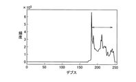
- FIG. 4 is a diagram illustrating an example of a histogram of a depth map.
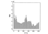
- FIG. 5 is an example of a histogram obtained by extending a histogram of a region having a depth value in a predetermined range to the maximum range of the depth value in the depth map.
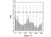
- FIG. 6 is a diagram for dividing the histogram class of FIG. 5 into the number of depth layers.
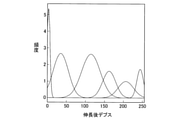
- FIG. 7 is a diagram illustrating an example of the result of clustering by a plurality of depth layers by GMM.
- FIG. 8 is a diagram showing minimum points and maximum points in the mapping function generated by the mapping function generation unit.
- FIG. 9 is a diagram illustrating an example of replacement of a minimum point and a maximum point.
- FIG. 10 is a diagram illustrating an example of a mapping function connecting points after replacement.
- FIG. 11 is a diagram illustrating an example of a mapping function in which points after replacement are connected and smoothed.
- FIG. 12 is an example of a histogram in which the histogram expanded to the maximum range is returned to the depth value in the predetermined range before expansion.
- FIG. 13 is a flowchart illustrating a processing method by the processing apparatus.
- FIG. 14 is a diagram illustrating a hardware configuration of a computer used in a processing device.
- the processing device (mapping function adjusting device) 1 updates the depth map data used for generating a three-dimensional image to the depth map data that allocates a wide range to a predetermined object.
- the processing device 1 can appropriately calculate a mapping function for updating the depth map without leading to an abnormal solution. Further, the processing device 1 can calculate the mapping function faster by reducing the processing load as compared with the conventional case.
- the processing device 1 includes a depth map data 11, a mapping function data 12, a histogram generation unit 21, a mapping function generation unit 22, an adjustment unit 23, and an update unit 24.
- the depth map data 11 and the mapping function data 12 are data stored in the memory 902 or the storage 903.
- the histogram generation unit 21, the mapping function generation unit 22, the adjustment unit 23, and the update unit 24 are functional units implemented in the processing device 1 by the execution of the CPU 901.
- the depth map data 11 is used to generate a three-dimensional image.
- the depth map data 11 defines the depth value of the area.
- a region is a unit that specifies a position on a depth map. In the embodiment of the present invention, one area is one pixel, but it may be a plurality of pixels. If the range of the mapping function is represented by 8 bits, the depth value is represented in grayscale with a range of 0-255. If the range of the mapping function is represented in 16 bits, the depth value is represented in grayscale with a range of 0-65535.
- the depth map data 11 is referred to by the histogram generation unit 21 and updated by the update unit 24.
- FIG. 2 shows an example of the depth map data 11 before the update
- FIG. 3 shows an example of the depth map data 11 after the update by the update unit 24.
- the difference in the shade of the central person becomes clearer than the depth map data 11 before the update shown in FIG.
- the mapping function data 12 is data that specifies a function that converts the depth value of the depth map data 11 before the update into the depth value of the depth map data after the update by the update unit 24.
- the mapping function is used to update the depth map data 11 before the update to the depth map data 11 that allocates a wide range to a predetermined object.
- the histogram generation unit 21 generates a histogram from the depth map data 11 in which a plurality of classes in which depth values are divided and the number of regions belonging to the classes are associated with each other.
- the histogram generation unit 21 generates a histogram in which a plurality of classes in which the maximum range of depth values is divided and the number of regions belonging to the classes are associated with each other.
- the generated histogram is referred to when the mapping function is generated by the mapping function generation unit 22.
- the histogram generation unit 21 divides 0-255, which is the maximum range of depth values, into a plurality of classes.
- the class is an interval of depth values for summarizing the frequency of depth values in the histogram.
- the first class corresponds to the depth value range "1".
- the histogram generation unit 21 counts the number of regions having a depth value of “0”, the number of regions having a depth value of “1”, ..., And the number of regions in increments of a depth value of “1” to generate a histogram.
- the histogram generation unit 21 has the number of regions of the depth value “0” or “1” and the region of the depth value “2” or “3”. The number, ..., And the number of regions are counted in increments of the depth value "2" to generate a histogram.
- the mapping function generation unit 22 generates a mapping function from the generated histogram.
- the histogram generation unit 21 is mainly composed of a histogram generated by associating a plurality of classes that divide the maximum range of depth values with the number of regions belonging to the classes, except for the regions at both ends including the upper limit value and the lower limit value of the depth values. A fine histogram may be generated for the region.
- the histogram generation unit 21 deletes the class corresponding to the predetermined number of regions from the upper limit of the depth value and the class corresponding to the predetermined number of regions from the lower limit of the depth value, and the depth corresponding to the deleted histogram class.
- the range of values may be extended to the maximum range and the histogram may be updated.
- the mapping function generation unit 22 generates a mapping function from the updated histogram.
- a histogram formed in the maximum range of depth value 0-255 is updated to a histogram expressed in detail in a predetermined range.
- a histogram shown in FIG. 4 a case where the class corresponding to the number of regions of 5% from the upper limit value and the class corresponding to the number of regions of 5% from the lower limit value are deleted will be described.
- the example shown in FIG. 4 shows a histogram in the depth range 0-255.
- the case where the class to be deleted is indicated by a ratio will be described, but it may be indicated by a numerical value such as the number of cumulative regions.
- the histogram generation unit 21 specifies a range of depth values in which the cumulative number of regions is 5% of the total number of regions from the lower limit of the depth value 0, and deletes the histogram of the specified depth value range from the histogram. ..
- the histogram generation unit 21 specifies a range of depth values in which the cumulative number of regions is 5% of the total number of regions from the upper limit of the depth value 255, and deletes the histogram of the range of depth values specified from the histogram.
- a histogram in the range of about 175-240 indicated by the arrow in FIG. 4 remains.
- the histogram generation unit 21 extends the deleted histogram to 0-255, which is the maximum range, and updates the histogram.
- 0-255 which is the maximum range
- the histogram generation unit 21 obtains the histogram shown in FIG. 5 by extending the range of 175-240 before deletion to the range of 0-255.
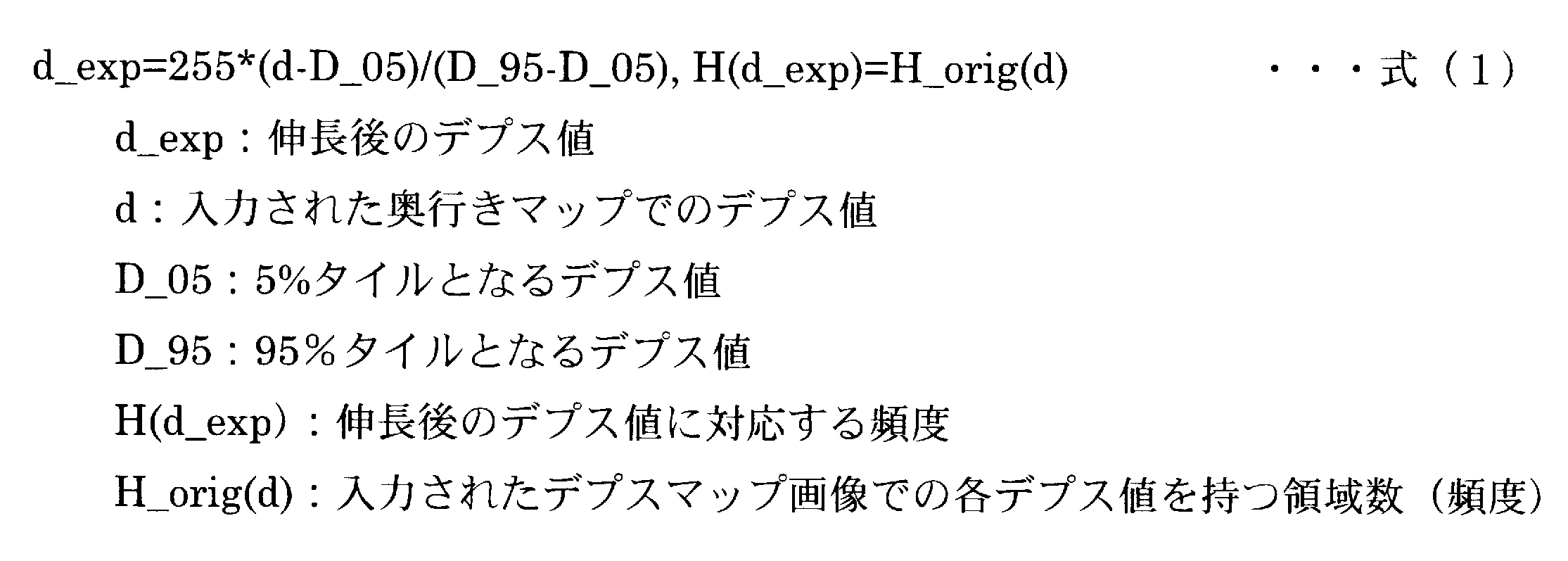
- the depth value d_exp after expansion and the depth value d on the depth map before expansion are converted by the equation (1).
- the mapping function generation unit 22 clusters the histogram into a plurality of depth layers having a Gaussian distribution shape, expands the width of the class belonging to the predetermined depth layer, and expands the depth value before expansion in the depth map data 11 after expansion. Generate a mapping function that converts to the depth value of.
- the width of the class belonging to the depth layer is specified in the histogram by the number of classes corresponding to the minimum value to the maximum value of the depth value of the region belonging to the depth layer.
- the generated mapping function is stored as mapping function data 12.
- the mapping function generation unit 22 generates a mapping function by, for example, the method described in Non-Patent Document 1.
- the mapping function generation unit 22 clusters, for example, the histogram shown in FIG. 5 into a plurality of Gaussian distribution shapes.
- One Gaussian distribution shape is called a depth layer.
- the mapping function generation unit 22 divides the histogram class generated by the histogram generation unit 21 into the number of depth layers specified by the user or the like. In the example shown in FIG. 6, the number of depth layers is 9. The mapping function generation unit 22 specifies the depth value having the maximum frequency in each division as a representative value. In the example shown in FIG. 6, the points indicated by black circles are the representative depth values.
- the number of depth layers specified by the user etc. is used to extract some representative values, so there is no particular limitation. If the number of depth layers is large, it may take time for the subsequent clustering process.
- the number of depth layers is preferably set to a value that does not become too large than the number of layers that the user wants to classify in the three-dimensional image.
- the mapping function generation unit 22 performs clustering by using the representative value in each division as the initial value of the average value of each Gaussian distribution in the GMM (Gaussian mixture model). As a result of clustering, the mapping function generation unit 22 identifies a plurality of depth layers having a Gaussian distribution shape, as shown in FIG. 7. In the example shown in FIG. 7, seven depth layers are identified.
- the mapping function generation unit 22 expands the width of the class of the predetermined depth layer, and converts the depth value before expansion in the depth map data 11 into the depth value after expansion. Generate a function.
- the mapping function generation unit 22 extends the designated depth layer in the left-right direction of FIG. 7 so that the depth layer designated by the user's specification or the like is represented by a wider depth value, and is designated. Widen the class to which the depth layer belongs. For example, if the width of the class to which the specified depth layer belongs is a 70-depth value (70-class), the specified depth layer is expanded in the left-right direction so that the value is larger than the 70-depth value, such as 140-depth value. ..
- the mapping function generation unit 22 generates a mapping function that converts the depth value before expansion in the depth map data 11 into the depth value after expansion of the width of the class to which the designated depth layer belongs.
- the mapping function generation unit 22 determines the mapping function in the portion where the depth layers overlap, in consideration of the weight given to each depth layer.
- the weight given to each depth layer may be proportional to the degree of elongation of each depth layer.
- the mapping function generation unit 22 may further extend the depth layer adjacent to the predetermined depth layer with an extension degree lower than the extension degree of the predetermined depth layer to generate the mapping function.
- the degree of extension of each layer may be calculated so that the degree of extension of adjacent layers and the degree of extension of adjacent layers have a normal distribution centered on the degree of extension (volume) of the specified depth layer. ..
- mapping function is expressed as, for example, equation (2).
- the adjustment unit 23 identifies an area in the mapping function in which the depth value before expansion and the depth value after expansion have a negative correlation, and in the specified area. Adjust the mapping function so that the depth value before extension and the depth value after extension have a positive correlation.
- the adjusting unit 23 geometrically analyzes the mapping function, identifies a point where the relationship between the depth values before expansion and the relationship between the depth values after expansion are inverted, and adjusts the mapping function.
- the adjustment unit 23 detects the minimum point and the maximum point in the mapping function generated by the mapping function generation unit 22.
- the minimum point and the maximum point are indicated by circles.
- the adjusting unit 23 has a first corresponding point having the same post-extended depth value as the local minimum point and a pre-extended depth value different from the local minimum point, and a maximum post-extended depth value having the same maximum point. Identify a second correspondence with different pre-stretching depth values.
- the adjusting unit 23 adjusts the mapping function by replacing the interval specified by the minimum point and the maximum point of the mapping function with a line connecting the first corresponding point and the second corresponding point.
- the adjusting unit 23 sets the point where the depth value before expansion is the minimum in the mapping function as the first corresponding point when there is no first corresponding point with respect to the minimum point, and sets the second corresponding point with respect to the maximum point. If there is no corresponding point, the point where the depth value before expansion is maximum in the mapping function is set as the second corresponding point.
- the range of mapping functions is 0-255.
- the first corresponding point is the output point of the mapping function when the input is 0.
- the second corresponding point is the output point of the mapping function when the input is 255.
- the range of the mapping function is represented by 16 bits, it is 0 to 65535, so that the first correspondence point and the second correspondence point are the output points of the mapping function when the input is 0 or 65535, respectively. ..
- the input is the input of the mapping function and is the depth value before extending the predetermined depth layer.
- the output is the output of the mapping function, which is the depth value after extending a given depth layer.
- the adjusting unit 23 identifies the maximum points P1 and P3 and the minimum points P2 and P4.
- the adjusting unit 23 specifies the point P1'on the mapping function, which has the same output depth value as the maximum point P1 but different input depth value, as a corresponding point corresponding to the maximum point P1. Since there is no point of the mapping function whose output depth value is the same as that of the minimum point P2 but the input depth value is different, the adjusting unit 23 sets the point P2'on the mapping function where the input depth value is 0 to the minimum point P2. Specify as a corresponding point corresponding to. The adjusting unit 23 adjusts the mapping function so as to include a line segment passing through P1'and P2'.
- the adjustment unit 23 specifies the point P3'on the mapping function, which has the same output depth value as the maximum point P3 but different input depth value, as a corresponding point corresponding to the maximum point P3.
- the point P4'of the mapping function having the same output depth value as the minimum point P4 but different input depth value is specified as a corresponding point corresponding to the minimum point P4.
- the adjusting unit 23 adjusts the mapping function so as to include a line segment passing through P3'and P4'.
- FIG. 10 shows a region in which the depth value before expansion and the depth value after expansion have a negative correlation in the mapping function shown in FIG. 8, so that the depth value before expansion and the depth value after expansion have a positive correlation. It is a mapping function adjusted to.
- the adjusting unit 23 may perform smoothing processing on the adjusted mapping function shown in FIG. 10 to obtain a mapping function having a smooth curve as shown in FIG. In the smoothing process, for example, third-order spline interpolation is used.
- the adjusting unit 23 adjusts the depth value before extension and the depth value after extension so that they have a positive correlation.
- the adjusting unit 23 can output a mapping function capable of assigning a wide range of depth values to a predetermined depth layer while maintaining the magnitude relationship of the depth values before expansion.
- the adjustment unit 23 may adjust the mapping function by another method.
- the adjusting unit 23 searches for the first corresponding point and the second corresponding point within a predetermined range including the minimum point and the marked maximum point. When there is no first correspondence point, the adjustment unit 23 sets the point where the depth value before expansion becomes the minimum in the predetermined range of the mapping function as the first correspondence point, and when there is no second correspondence point, the adjustment unit 23 sets the mapping function.
- the point where the depth value before extension becomes maximum in a predetermined range is defined as the second corresponding point.
- the adjusting unit 23 has, for example, a predetermined range that is twice the range specified by the depth value before the extension of the minimum point and the depth value before the extension of the maximum point.
- the adjusting unit 23 has a predetermined range centered on the range of the depth value before the extension of P1 and the depth value before the extension of P2, and is twice the range.
- the adjusting unit 23 searches for a first corresponding point and a second corresponding point within the predetermined range. When the corresponding point is not found in the range, the adjusting unit 23 sets the point on the mapping function in the upper limit value or the lower limit value of the input in the predetermined range as the corresponding point.
- the adjusting unit 23 limits the search range of the corresponding points, so that the processing load can be reduced. Further, the adjusting unit 23 can adjust the mapping function so as to further follow the shape of the original mapping function as a result of limiting the search range of the corresponding points.
- the mapping function input to the adjustment unit 23 When the mapping function input to the adjustment unit 23 is generated from the histogram with both ends removed, such as the range of the arrow shown in FIG. 4, the input value of the mapping function is different from the depth value in the depth map data 11.
- the adjustment unit 23 converts the range of the depth value before the extension of the adjusted mapping function into the range of the depth value corresponding to the class of the histogram after the deletion. At this time, in the depth value before expansion, the deleted range is converted to 0 or 255.
- the adjustment unit 23 sets the adjustment unit 23. Adjust the mapping function to compress the input range 0-255 to 175-240.
- the mapping function converts the depth value before expansion to 0 when the depth value before expansion is 174 or less, and converts it to 255 when the depth value before expansion is 240 or more.
- the adjusting unit 23 obtains the mapping function shown in FIG.
- the update unit 24 is a mapping function adjusted by the adjustment unit 23, and updates the depth value of the depth map data 11. As a result, the processing device 1 obtains the depth map data 11 that allocates a wide range to a predetermined object.
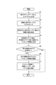
- step S1 the processing device 1 generates a histogram from the depth map data 11.
- step S2 the processing apparatus 1 clusters the histogram generated in step S1 into a plurality of depth layers.
- step S3 the processing apparatus 1 extends the width of the class of the designated depth layer among the plurality of depth layers clustered in step S2.
- the processing device 1 may also extend a depth layer adjacent to the designated depth layer.
- step S4 the processing apparatus 1 generates a mapping function that converts the depth value before expansion in step S3 into the depth value after expansion.
- step S5 the processing apparatus 1 determines whether or not there is an area having a negative correlation in the mapping function generated in step S4. If there is no area with a negative correlation, the processing apparatus 1 ends the processing.
- step S6 the processing apparatus 1 adjusts the mapping function so as to have a positive correlation in the area having a negative correlation.
- step S7 the processing apparatus 1 updates the depth value of the depth map data 11 with the mapping function adjusted in step S6, and ends the processing.
- the processing apparatus 1 pays attention to the occurrence of a minimum point and a maximum point in a portion having a negative correlation in the mapping function, and linearizes the portion including the minimum point and the maximum point. As a result, optimization can be achieved in a shorter time than in the prior art. For example, in the prior art, the processing that required 5072 seconds can be shortened to 15.4 seconds by the processing apparatus 1 according to the embodiment of the present invention. Further, since the processing device 1 geometrically eliminates the region of negative correlation in the mapping function, it does not result in an abnormal solution.
- the processing apparatus 1 can enhance the stereoscopic effect in a three-dimensional image by expanding and compressing the depth range of the entire image.
- the processing device 1 can appropriately calculate the mapping function used for converting the depth map into the depth map that allocates a wide range to a predetermined object.
- the processing device 1 of the present embodiment described above includes, for example, a CPU (Central Processing Unit, processor) 901, a memory 902, a storage 903 (HDD: Hard Disk Drive, SSD: Solid State Drive), and a communication device 904.
- a general purpose computer system including an input device 905 and an output device 906 is used.
- each function of the processing device 1 is realized by executing the processing program loaded on the memory 902 by the CPU 901.
- the processing device 1 may be mounted on one computer or may be mounted on a plurality of computers. Further, the processing device 1 may be a virtual machine mounted on a computer.
- the program of the processing device 1 can be stored in a computer-readable recording medium such as an HDD, SSD, USB (Universal Serial Bus) memory, CD (Compact Disc), DVD (Digital Versatile Disc), or distributed via a network. You can also do it.
- a computer-readable recording medium such as an HDD, SSD, USB (Universal Serial Bus) memory, CD (Compact Disc), DVD (Digital Versatile Disc), or distributed via a network. You can also do it.
- the present invention is not limited to the above embodiment, and many modifications can be made within the scope of the gist thereof.
- Processing device 11 Depth map data 12 Mapping function data 21 Histogram generation unit 22 Mapping function generation unit 23 Adjustment unit 24 Update unit 901 CPU 902 Memory 903 Storage 904 Communication device 905 Input device 906 Output device
Landscapes
- Engineering & Computer Science (AREA)
- Multimedia (AREA)
- Signal Processing (AREA)
- Image Processing (AREA)
- Testing, Inspecting, Measuring Of Stereoscopic Televisions And Televisions (AREA)
- Image Analysis (AREA)
Abstract
マッピング関数調整装置1は、領域のデプス値を対応づけた奥行きマップデータ11におけるデプス値の範囲を区分する複数の階級毎に、階級に属する領域数を対応づけたヒストグラムを生成するヒストグラム生成部21と、ヒストグラムを、ガウス分布形状を有する複数の奥行きレイヤにクラスタリングし、所定の奥行きレイヤの階級の幅を伸長し、奥行きマップデータ11における伸長前のデプス値を、伸長後のデプス値に変換するマッピング関数を生成するマッピング関数生成部22と、マッピング関数において、伸長前のデプス値と伸長後のデプス値が負の相関を有する区域を特定し、特定された区域において伸長前のデプス値と伸長後のデプス値が正の相関を有するように、マッピング関数を調整する調整部23を備える。
Description
本発明は、マッピング関数調整装置、マッピング関数調整方法およびプログラムに関する。
三次元画像を生成するために用いられる奥行きマップ(Depth map)がある。奥行きマップは、視点からの距離情報を濃淡で表現する。一般的に、奥行きマップが表現できる範囲が制限されている。例えば、0~255の範囲のグレースケールで、各画素の奥行きが定義される。
注目する物体部分に広い範囲を割り当てることで、注目する物体の立体感を強調する手法が提案されている(非特許文献1参照)。注目する物体におけるデプス値の範囲を伸長することにより、マッピング関数の反転が生じる。非特許文献1は、反転したマッピング関数に対して、非線形最小二乗法を用いたカーブフィッティングを用いて対処する。
Sangwoo Lee, Younghui Kim, Jungjin Lee, Kyehyun Kim, Kyunghan Lee and Junyong Noh, "Depth manipulation using disparity histogram analysis for stereoscopic 3D", The Visual Computer 30(4):455-465, April 2014.
しかしながら非特許文献1に記載の方法は、最適化問題を解くため、マッピング関数の算出に時間がかかる場合がある。また非特許文献1に記載の方法は、最適化問題を解く結果、マッピングの反転箇所が解消されず、逆に反転箇所がいくつも生じるような異常解に帰着する場合もある。
本発明は、上記事情に鑑みてなされたものであり、本発明の目的は、奥行きマップを、所定のオブジェクトに広い範囲を割り当てる奥行きマップに変換するために用いられるマッピング関数を、適切に算出可能な技術を提供することである。
本発明の一態様のマッピング関数調整装置は、領域のデプス値を定義する奥行きマップデータから、デプス値の範囲を区分する複数の階級毎に、階級に属する領域数を対応づけたヒストグラムを生成するヒストグラム生成部と、ヒストグラムを、ガウス分布形状を有する複数の奥行きレイヤにクラスタリングし、所定の奥行きレイヤが属する階級の幅を伸長し、奥行きマップデータにおける伸長前のデプス値を、伸長後のデプス値に変換するマッピング関数を生成するマッピング関数生成部と、マッピング関数において、伸長前のデプス値と伸長後のデプス値が負の相関を有する区域を特定し、特定された区域において伸長前のデプス値と伸長後のデプス値が正の相関を有するように、マッピング関数を調整する調整部を備える。
本発明の一態様のマッピング関数調整方法は、コンピュータが、領域のデプス値を定義する奥行きマップデータから、デプス値の範囲を区分する複数の階級毎に、階級に属する領域数を対応づけたヒストグラムを生成するステップと、コンピュータが、ヒストグラムを、ガウス分布形状を有する複数の奥行きレイヤにクラスタリングし、所定の奥行きレイヤが属する階級の幅を伸長し、奥行きマップデータにおける伸長前のデプス値を、伸長後のデプス値に変換するマッピング関数を生成するステップと、コンピュータが、マッピング関数において、伸長前のデプス値と伸長後のデプス値が負の相関を有する区域を特定し、特定された区域において伸長前のデプス値と伸長後のデプス値が正の相関を有するように、マッピング関数を調整するステップを備える。
本発明の一態様は、上記処理装置として、コンピュータを機能させる処理プログラムである。
本発明によれば、奥行きマップを、所定のオブジェクトに広い範囲を割り当てる奥行きマップに変換するために用いられるマッピング関数を、適切に算出可能な技術を提供することができる。
以下、図面を参照して、本発明の実施形態を説明する。図面の記載において同一部分には同一符号を付し説明を省略する。
(処理装置)
本発明の実施の形態にかかる処理装置(マッピング関数調整装置)1は、三次元画像を生成するために用いられる奥行きマップデータを、所定のオブジェクトに広い範囲を割り当てる奥行きマップデータに更新する。処理装置1は、奥行きマップを更新するためのマッピング関数を、異常解に導くことなく適切に、算出することができる。また処理装置1は、従来よりも処理負担を軽減して、早く、マッピング関数を算出することができる。
本発明の実施の形態にかかる処理装置(マッピング関数調整装置)1は、三次元画像を生成するために用いられる奥行きマップデータを、所定のオブジェクトに広い範囲を割り当てる奥行きマップデータに更新する。処理装置1は、奥行きマップを更新するためのマッピング関数を、異常解に導くことなく適切に、算出することができる。また処理装置1は、従来よりも処理負担を軽減して、早く、マッピング関数を算出することができる。
処理装置1は、奥行きマップデータ11、マッピング関数データ12、ヒストグラム生成部21、マッピング関数生成部22、調整部23および更新部24を備える。奥行きマップデータ11およびマッピング関数データ12は、メモリ902またはストレージ903に記憶されるデータである。ヒストグラム生成部21、マッピング関数生成部22、調整部23および更新部24は、CPU901の実行によって処理装置1に実装される機能部である。
奥行きマップデータ11は、三次元画像を生成するために用いられる。奥行きマップデータ11は、領域のデプス値を定義する。領域は、奥行きマップにおける位置を特定する単位である。本発明の実施の形態において1つの領域は、1つの画素であるが、複数の画素であっても良い。マッピング関数の範囲が8ビットで表現される場合、デプス値は、0-255の範囲を有するグレースケールで表現される。マッピング関数の範囲が16ビットで表現される場合、デプス値は、0-65535の範囲を有するグレースケールで表現される。奥行きマップデータ11は、ヒストグラム生成部21により参照され、更新部24により更新される。
図2に、更新前の奥行きマップデータ11の一例を示し、図3に、更新部24による更新後の奥行きマップデータ11の一例を示す。図3に示す更新後の奥行きマップデータ11において、中央の人物の濃淡の差が、図2に示す更新前の奥行きマップデータ11に比べて明確になることがわかる。
マッピング関数データ12は、更新前の奥行きマップデータ11のデプス値を、更新部24による更新後の奥行きマップデータのデプス値に変換する関数を特定するデータである。マッピング関数は、更新前の奥行きマップデータ11を、所定のオブジェクトに広い範囲を割り当てる奥行きマップデータ11に更新するために用いられる。
ヒストグラム生成部21は、奥行きマップデータ11から、デプス値を区分した複数の階級と、階級に属する領域数を対応づけたヒストグラムを生成する。ヒストグラム生成部21は、デプス値の最大範囲を区分した複数の階級と、階級に属する領域数を対応づけたヒストグラムを生成する。生成したヒストグラムは、マッピング関数生成部22によるマッピング関数の生成の際に参照される。ヒストグラム生成部21は、デプス値の最大範囲である0-255を、複数の階級に区分する。階級は、ヒストグラムにおいて、デプス値の頻度を集計するためのデプス値の区間である。本発明の実施の形態において、1階級は、デプス値の範囲“1”に対応する。ヒストグラム生成部21は、デプス値“0”の領域数、デプス値“1”の領域数、・・・と、デプス値“1”刻みで領域数をカウントして、ヒストグラムを生成する。他の例として、1階級がデプス値の範囲“2”に対応する場合、ヒストグラム生成部21は、デプス値“0”または“1”の領域数、デプス値“2”または“3”の領域数、・・・と、デプス値“2”刻みで領域数をカウントして、ヒストグラムを生成する。マッピング関数生成部22は、生成したヒストグラムからマッピング関数を生成する。
ヒストグラム生成部21は、デプス値の最大範囲を区分した複数の階級と、階級に属する領域数を対応づけて生成したヒストグラムから、デプス値の上限値および下限値を含む両端の領域を除き、主要領域について、精細なヒストグラムを生成しても良い。ヒストグラム生成部21は、デプス値の上限値から所定の領域数に対応する階級と、デプス値の下限値から所定の領域数に対応する階級を削除し、削除後のヒストグラムの階級に対応するデプス値の範囲を、最大範囲に伸長して、ヒストグラムを更新しても良い。マッピング関数生成部22は、更新後のヒストグラムからマッピング関数を生成する。
例えば、デプス値が0-255の最大範囲で形成されたヒストグラムを、所定範囲において精細に表現したヒストグラムに更新する場合を説明する。例えば図4に示すようなヒストグラムについて、上限値から5%の領域数に対応する階級と、下限値から5%の領域数に対応する階級を削除する場合を説明する。図4に示す例は、デプス値の範囲0-255のヒストグラムを示す。なお本発明の実施の形態において、削除する階級を割合で示す場合を説明するが、累積領域数などの数値で示しても良い。
ヒストグラム生成部21は、デプス値の下限値0から、累積領域数が全領域数の5%となるデプス値の範囲を特定して、ヒストグラムから、特定されたデプス値の範囲のヒストグラムを削除する。ヒストグラム生成部21は、デプス値の上限値255から、累積領域数が全領域数の5%となるデプス値の範囲を特定して、ヒストグラムから特定されたデプス値の範囲のヒストグラムを削除する。その結果、図4の矢印が示す約175-240の範囲のヒストグラムが残る。
ヒストグラム生成部21は、図5に示すように、削除後のヒストグラムを、最大範囲である0-255に伸長して、ヒストグラムを更新する。図4に示す例において、デプス値の範囲0-255のうち、削除により約175-240の範囲が残る。ヒストグラム生成部21は、削除前の175-240の範囲を、0-255の範囲に伸長することで、図5に示すヒストグラムを得る。
伸長後のデプス値d_expと、伸長前の奥行きマップ上のデプス値dは、式(1)により変換される。
これにより、領域数の少ない範囲をトリミングして、所定範囲のデプス値のヒストグラムを精細に表現することが可能になる。
マッピング関数生成部22は、ヒストグラムを、ガウス分布形状を有する複数の奥行きレイヤにクラスタリングし、所定の奥行きレイヤに属する階級の幅を伸長し、奥行きマップデータ11における伸長前のデプス値を、伸長後のデプス値に変換するマッピング関数を生成する。奥行きレイヤに属する階級の幅は、ヒストグラムにおいて、奥行きレイヤに属する領域のデプス値の最小値に対応する階級から最大値に対応する階級の数で特定される。生成したマッピング関数は、マッピング関数データ12として記憶される。マッピング関数生成部22は、例えば非特許文献1に記載の方法で、マッピング関数を生成する。
マッピング関数生成部22は、例えば図5に示すヒストグラムを、複数のガウス分布形状にクラスタリングする。1つのガウス分布形状は、奥行きレイヤと称される。
ガウス分布形状にクラスタリングする方法の一例を説明する。マッピング関数生成部22は、図6に示すように、ヒストグラム生成部21で生成したヒストグラムの階級を、ユーザ等により指定されたデプスレイヤ数に区分する。図6に示す例においてデプスレイヤ数は9である。マッピング関数生成部22は、各区分において、最大頻度となるデプス値を、代表値として特定する。図6に示す例において、黒丸で示した点が代表値となるデプス値である。
ユーザ等により指定されるデプスレイヤ数は、いくつかの代表値を抽出するために用いられるので、特に制限はない。デプスレイヤ数が大きい場合、後続のクラスタリング処理で時間を要する場合がある。デプスレイヤ数は、三次元画像においてユーザが区分したいレイヤ数よりも大きくなりすぎない値で、設定されることが好ましい。
マッピング関数生成部22は、各区分における代表値を、GMM(混合ガウスモデル:Gaussian mixture model)における各ガウス分布の平均値の初期値として、クラスタリングを行う。マッピング関数生成部22は、クラスタリングの結果、図7に示すように、ガウス分布形状を有する複数の奥行きレイヤを特定する。図7に示す例において、7つの奥行きレイヤが特定される。
複数の奥行きレイヤが特定されると、マッピング関数生成部22は、所定の奥行きレイヤの階級の幅を伸長し、奥行きマップデータ11における伸長前のデプス値を、伸長後のデプス値に変換するマッピング関数を生成する。マッピング関数生成部22は、ユーザの指定等により指定された奥行きレイヤが、より広いデプス値で表現されるように、指定された奥行きレイヤを、図7の左右方向に伸長して、指定された奥行きレイヤの属する階級の幅を広げる。例えば、指定された奥行きレイヤの属する階級の幅が70デプス値(70階級)の場合、140デプス値など、70デプス値よりも大きい値になるように、指定された奥行きレイヤを左右方向に広げる。マッピング関数生成部22は、奥行きマップデータ11における伸長前のデプス値を、指定された奥行きレイヤの属する階級の幅を伸長した後のデプス値に変換するマッピング関数を生成する。マッピング関数生成部22は、各奥行きレイヤ与えられた重みを考慮して、奥行きレイヤが重複する部分におけるマッピング関数を決定する。各奥行きレイヤに与えられる重みは、各奥行きレイヤの伸長度に比例しても良い。
このとき、マッピング関数生成部22は、さらに、所定の奥行きレイヤに隣接する奥行きレイヤを、所定の奥行きレイヤの伸長度よりも低い伸長度で伸長して、マッピング関数を生成しても良い。例えば、指定された奥行きレイヤの伸長度(ボリューム)を中心に、隣接するレイヤの伸長度、さらに隣接するレイヤの伸長度が正規分布となるように、各レイヤの伸長度が算出されても良い。指定された奥行きレイヤの伸長度に対する、隣接する奥行きレイヤの伸長度の割合は、例えば、f(±1)/f(0)=0.24/0/4=0.6倍となる。なお、fは、標準正規分布関数である。指定された奥行きレイヤに隣接する奥行きレイヤについても、伸長することにより、三次元画像において、滑らかな奥行きを表現することができる。
マッピング関数は、例えば式(2)のように表現される。

マッピング関数生成部22によってマッピング関数が生成されると、調整部23は、マッピング関数において、伸長前のデプス値と伸長後のデプス値が負の相関を有する区域を特定し、特定された区域において伸長前のデプス値と伸長後のデプス値が正の相関を有するように、マッピング関数を調整する。調整部23は、マッピング関数を幾何的に解析して、伸長前のデプス値の関係と、伸長後のデプス値の関係とが反転する箇所を特定して、マッピング関数を調節する。
調整部23は、マッピング関数生成部22が生成したマッピング関数において、極小点および極大点を検出する。図8に示す例において、極小点および極大点を丸印で示す。
調整部23は、極小点と同じ伸長後のデプス値を有し極小点と異なる伸長前のデプス値を有する第1の対応点と、極大点と同じ伸長後のデプス値を有し極大点と異なる伸長前のデプス値を有する第2の対応点を特定する。調整部23は、マッピング関数の極小点および極大点で特定される区間を、第1の対応点と第2の対応点とを接続した線に置き換えて、マッピング関数を調整する。
ここで調整部23は、極小点に対して第1の対応点がない場合、マッピング関数において伸長前のデプス値が最小となる点を第1の対応点とし、極大点に対して第2の対応点がない場合、マッピング関数において伸長前のデプス値が最大となる点を第2の対応点とする。本発明の実施の形態において、マッピング関数の範囲は、0-255である。第1の対応点は、入力が0のときのマッピング関数の出力の点となる。第2の対応点は、入力が255のときのマッピング関数の出力の点となる。マッピング関数の範囲が16ビットで表現される場合、0-65535であるので、第1の対応点および第2の対応点は、それぞれ入力が0または65535のときのマッピング関数の出力の点となる。
図9を参照して、具体的に説明する。図9において入力は、マッピング関数の入力で、所定の奥行きレイヤを伸長する前のデプス値である。出力は、マッピング関数の出力で、所定の奥行きレイヤを伸長した後のデプス値である。図9に示す例において調整部23は、極大点P1およびP3と、極小点P2およびP4を特定する。
調整部23は、極大点P1と出力のデプス値が同じで入力のデプス値が異なるマッピング関数上の点P1’を、極大点P1に対応する対応点として特定する。極小点P2と出力のデプス値が同じで入力のデプス値が異なるマッピング関数の点がないので、調整部23は、入力のデプス値が0となるマッピング関数上の点P2’を、極小点P2に対応する対応点として特定する。調整部23は、P1’およびP2’を通る線分を含むように、マッピング関数を調整する。
調整部23は、極大点P3と出力のデプス値が同じで入力のデプス値が異なるマッピング関数上の点P3’を、極大点P3に対応する対応点として特定する。極小点P4と出力のデプス値が同じで入力のデプス値が異なるマッピング関数の点P4’を、極小点P4に対応する対応点として特定する。調整部23は、P3’およびP4’を通る線分を含むように、マッピング関数を調整する。
図10は、図8に示すマッピング関数において、伸長前のデプス値と伸長後のデプス値が負の相関を有する区域を、伸長前のデプス値と伸長後のデプス値が正の相関を有するように調整したマッピング関数である。調整部23は、図10に示す調整後のマッピング関数に対してスムージング処理を施して、図11に示すような、カーブが滑らかなマッピング関数を得ても良い。スムージング処理では、例えば、三次スプライン補間が利用される。
調整部23は、伸長前のデプス値と伸長後のデプス値が、正の相関を有するように、調整する。調整部23は、伸長前のデプス値の大小関係を維持しつつ、所定の奥行きレイヤに広いデプス値の範囲を割り当てることが可能なマッピング関数を出力することができる。
調整部23は、他の方法によってマッピング関数を調整しても良い。調整部23は、極小点および記極大点を含む所定範囲内で、第1の対応点および第2の対応点を探索する。調整部23は、第1の対応点がない場合、マッピング関数の所定範囲において伸長前のデプス値が最小となる点を第1の対応点とし、第2の対応点がない場合、マッピング関数の所定範囲において伸長前のデプス値が最大となる点を第2の対応点とする。
調整部23は、例えば、極小点の伸長前のデプス値と、極大点の伸長前のデプス値で特定される範囲の2倍の範囲を、所定範囲とする。図9に示す例において、調整部23は、P1の伸長前のデプス値と、P2の伸長前のデプス値の範囲を中心に、その範囲の2倍の範囲を、所定範囲とする。調整部23は、その所定範囲内において、第1の対応点および第2の対応点を探索する。範囲内に対応点が見つからない場合、調整部23は、所定範囲の入力の上限値または下限値におけるマッピング関数上の点を対応点とする。
これにより調整部23は、対応点の探索範囲を制限するので、処理負担を軽減することができる。また調整部23は、対応点の探索範囲を制限する結果、元のマッピング関数の形状にさらに沿う様に、マッピング関数を調整することができる。
調整部23に入力されたマッピング関数が、図4に示す矢印の範囲など、両端を削除したヒストグラムから生成された場合、マッピング関数の入力値は、奥行きマップデータ11におけるデプス値とは異なる。調整部23は、調整したマッピング関数の伸長前のデプス値の範囲を、削除後のヒストグラムの階級に対応するデプス値の範囲に変換する。このとき、伸長前のデプス値において、削除された範囲は、0または255に変換される。
図4に示す例のように、デプス値の最大範囲0-255のうちの約175-240の範囲を取り出し、0-255の範囲に伸長してマッピング関数を作成する場合、調整部23は、入力の範囲0-255を、175-240に圧縮するようにマッピング関数を調整する。マッピング関数は、伸長前のデプス値が、174以下の場合、0に変換し、伸長前のデプス値が、240以以上の場合、255に変換する。調整部23は、図12に示すマッピング関数を得る。
更新部24は、調整部23によって調整されたマッピング関数で、奥行きマップデータ11のデプス値を更新する。これにより処理装置1は、所定のオブジェクトに広い範囲を割り当てる奥行きマップデータ11を得る。
図13を参照して、本発明の実施の形態に係る処理装置1による処理方法を説明する。
まずステップS1において処理装置1は、奥行きマップデータ11から、ヒストグラムを生成する。ステップS2において処理装置1は、ステップS1で生成したヒストグラムから、複数の奥行きレイヤにクラスタリングする。
ステップS3において処理装置1は、ステップS2でクラスタリングした複数の奥行きレイヤのうち、指定された奥行きレイヤの階級の幅を伸長する。処理装置1は、指定された奥行きレイヤに隣接する奥行きレイヤも伸長しても良い。ステップS4において処理装置1は、ステップS3における伸長前のデプス値を、伸長後のデプス値に変換するマッピング関数を生成する。
ステップS5において処理装置1は、ステップS4で生成したマッピング関数において、負の相関を有する区域があるか否かを判定する。負の相関を有する区域がない場合、処理装置1は処理を終了する。
負の相関を有する区域がある場合、ステップS6に進む。ステップS6において処理装置1は、負の相関を有する区域において、正の相関を有するようにマッピング関数を調整する。ステップS7において処理装置1は、ステップS6で調整したマッピング関数で、奥行きマップデータ11のデプス値を更新して、処理を終了する。
本発明の実施の形態に係る処理装置1は、マッピング関数において、負の相関を有する部分において極小点および極大点が発生することに着眼し、その極小点と極大点を含む部分を線形化することで、先行技術と比べて短時間での最適化を実現する。例えば従来技術では、5072秒要した処理を、本発明の実施の形態に係る処理装置1は、15.4秒に短縮することを可能とした。また処理装置1は、マッピング関数における負の相関の領域を幾何的に解消するので、異常解に帰着することはない。
奥行きマップを用いて三次元画像を生成する際、各デプスの絶対的な値はあまり重要ではなく、画像全体での各デプスの相対的な値が重要となる。本発明の実施の形態に係る処理装置1は、画像全体での奥行範囲を伸長し圧縮することで、三次元画像における立体感を強調することが可能になる。
このように本発明の実施の形態に係る処理装置1は、奥行きマップを、所定のオブジェクトに広い範囲を割り当てる奥行きマップに変換するために用いられるマッピング関数を、適切に算出することができる。
上記説明した本実施形態の処理装置1は、例えば、CPU(Central Processing Unit、プロセッサ)901と、メモリ902と、ストレージ903(HDD:Hard Disk Drive、SSD:Solid State Drive)と、通信装置904と、入力装置905と、出力装置906とを備える汎用的なコンピュータシステムが用いられる。このコンピュータシステムにおいて、CPU901がメモリ902上にロードされた処理プログラムを実行することにより、処理装置1の各機能が実現される。
なお、処理装置1は、1つのコンピュータで実装されてもよく、あるいは複数のコンピュータで実装されても良い。また処理装置1は、コンピュータに実装される仮想マシンであっても良い。
処理装置1のプログラムは、HDD、SSD、USB(Universal Serial Bus)メモリ、CD (Compact Disc)、DVD (Digital Versatile Disc)などのコンピュータ読取り可能な記録媒体に記憶することも、ネットワークを介して配信することもできる。
なお、本発明は上記実施形態に限定されるものではなく、その要旨の範囲内で数々の変形が可能である。
1 処理装置
11 奥行きマップデータ
12 マッピング関数データ
21 ヒストグラム生成部
22 マッピング関数生成部
23 調整部
24 更新部
901 CPU
902 メモリ
903 ストレージ
904 通信装置
905 入力装置
906 出力装置
11 奥行きマップデータ
12 マッピング関数データ
21 ヒストグラム生成部
22 マッピング関数生成部
23 調整部
24 更新部
901 CPU
902 メモリ
903 ストレージ
904 通信装置
905 入力装置
906 出力装置
Claims (8)
- 領域のデプス値を定義する奥行きマップデータから、前記デプス値の範囲を区分する複数の階級毎に、前記階級に属する領域数を対応づけたヒストグラムを生成するヒストグラム生成部と、
前記ヒストグラムを、ガウス分布形状を有する複数の奥行きレイヤにクラスタリングし、所定の奥行きレイヤが属する階級の幅を伸長し、前記奥行きマップデータにおける伸長前のデプス値を、伸長後のデプス値に変換するマッピング関数を生成するマッピング関数生成部と、
前記マッピング関数において、伸長前のデプス値と伸長後のデプス値が負の相関を有する区域を特定し、特定された区域において伸長前のデプス値と伸長後のデプス値が正の相関を有するように、前記マッピング関数を調整する調整部
を備えるマッピング関数調整装置。 - 前記調整部は、前記マッピング関数生成部が生成したマッピング関数において、極小点および極大点を検出し、前記マッピング関数の前記極小点および極大点で特定される区間を、前記極小点と同じ伸長後のデプス値を有し前記極小点と異なる伸長前のデプス値を有する第1の対応点と、前記極大点と同じ伸長後のデプス値を有し前記極大点と異なる伸長前のデプス値を有する第2の対応点とを接続した線に置き換えて、前記マッピング関数を調整する
請求項1に記載のマッピング関数調整装置。 - 前記調整部は、前記極小点に対して前記第1の対応点がない場合、前記マッピング関数において伸長前のデプス値が最小となる点を前記第1の対応点とし、前記極大点に対して前記第2の対応点がない場合、前記マッピング関数において伸長前のデプス値が最大となる点を前記第2の対応点とする
請求項2に記載のマッピング関数調整装置。 - 前記調整部は、前記極小点および前記極大点を含む所定範囲内で、前記第1の対応点がない場合、前記マッピング関数の前記所定範囲において伸長前のデプス値が最小となる点を第1の対応点とし、前記第2の対応点がない場合、前記マッピング関数の前記所定範囲において伸長前のデプス値が最大となる点を第2の対応点とする
請求項2に記載のマッピング関数調整装置。 - 前記マッピング関数生成部は、さらに、所定の奥行きレイヤに隣接する奥行きレイヤを、前記所定の奥行きレイヤの伸長度よりも低い伸長度で伸長して、前記マッピング関数を生成する
請求項1ないし4のいずれか1項に記載のマッピング関数調整装置。 - 前記ヒストグラム生成部は、前記デプス値の最大範囲を区分した複数の階級と、前記階級に属する領域数を対応づけたヒストグラムから、前記デプス値の上限値から所定の領域数に対応する階級と、前記デプス値の下限値から所定の領域数に対応する階級を削除して、
削除後のヒストグラムの階級に対応する前記デプス値の範囲を、前記最大範囲に伸長して、ヒストグラムを更新し、
前記マッピング関数生成部は、更新後のヒストグラムからマッピング関数を生成し、
前記調整部は、調整した前記マッピング関数の伸長前のデプス値の範囲を、前記削除後のヒストグラムの階級に対応する前記デプス値の範囲に変換する
請求項1ないし5のいずれか1項に記載のマッピング関数調整装置。 - コンピュータが、領域のデプス値を定義する奥行きマップデータから、前記デプス値の範囲を区分する複数の階級毎に、前記階級に属する領域数を対応づけたヒストグラムを生成するステップと、
前記コンピュータが、前記ヒストグラムを、ガウス分布形状を有する複数の奥行きレイヤにクラスタリングし、所定の奥行きレイヤが属する階級の幅を伸長し、前記奥行きマップデータにおける伸長前のデプス値を、伸長後のデプス値に変換するマッピング関数を生成するステップと、
前記コンピュータが、前記マッピング関数において、伸長前のデプス値と伸長後のデプス値が負の相関を有する区域を特定し、特定された区域において伸長前のデプス値と伸長後のデプス値が正の相関を有するように、前記マッピング関数を調整するステップ
を備えるマッピング関数調整方法。 - コンピュータを、請求項1ないし請求項6のいずれか1項に記載のマッピング関数調整装置として機能させるためのプログラム。
Priority Applications (2)
| Application Number | Priority Date | Filing Date | Title |
|---|---|---|---|
| JP2022538562A JP7485983B2 (ja) | 2020-07-22 | 2020-07-22 | マッピング関数調整装置、マッピング関数調整方法およびプログラム |
| PCT/JP2020/028527 WO2022018869A1 (ja) | 2020-07-22 | 2020-07-22 | マッピング関数調整装置、マッピング関数調整方法およびプログラム |
Applications Claiming Priority (1)
| Application Number | Priority Date | Filing Date | Title |
|---|---|---|---|
| PCT/JP2020/028527 WO2022018869A1 (ja) | 2020-07-22 | 2020-07-22 | マッピング関数調整装置、マッピング関数調整方法およびプログラム |
Publications (1)
| Publication Number | Publication Date |
|---|---|
| WO2022018869A1 true WO2022018869A1 (ja) | 2022-01-27 |
Family
ID=79729367
Family Applications (1)
| Application Number | Title | Priority Date | Filing Date |
|---|---|---|---|
| PCT/JP2020/028527 Ceased WO2022018869A1 (ja) | 2020-07-22 | 2020-07-22 | マッピング関数調整装置、マッピング関数調整方法およびプログラム |
Country Status (2)
| Country | Link |
|---|---|
| JP (1) | JP7485983B2 (ja) |
| WO (1) | WO2022018869A1 (ja) |
Cited By (1)
| Publication number | Priority date | Publication date | Assignee | Title |
|---|---|---|---|---|
| US12250721B2 (en) * | 2021-04-02 | 2025-03-11 | Qualcomm Incorporated | Starting a channel occupancy time after a directional listen-before-talk |
Citations (5)
| Publication number | Priority date | Publication date | Assignee | Title |
|---|---|---|---|---|
| JP2012134881A (ja) * | 2010-12-22 | 2012-07-12 | Toshiba Corp | マップ変換方法、マップ変換装置及びマップ変換プログラム |
| JP2012231405A (ja) * | 2011-04-27 | 2012-11-22 | Toshiba Corp | 奥行調整が可能な立体映像表示装置 |
| JP2013055629A (ja) * | 2011-08-10 | 2013-03-21 | Toshiba Corp | 映像出力装置及び映像出力方法 |
| US20140118507A1 (en) * | 2012-10-26 | 2014-05-01 | Korea Advanced Institute Of Science And Technology | Apparatus and method for depth manipulation of stereoscopic 3d image |
| JP2015503258A (ja) * | 2011-11-01 | 2015-01-29 | コーニンクレッカ フィリップス エヌ ヴェ | 突出ベース視差マッピング |
-
2020
- 2020-07-22 JP JP2022538562A patent/JP7485983B2/ja active Active
- 2020-07-22 WO PCT/JP2020/028527 patent/WO2022018869A1/ja not_active Ceased
Patent Citations (5)
| Publication number | Priority date | Publication date | Assignee | Title |
|---|---|---|---|---|
| JP2012134881A (ja) * | 2010-12-22 | 2012-07-12 | Toshiba Corp | マップ変換方法、マップ変換装置及びマップ変換プログラム |
| JP2012231405A (ja) * | 2011-04-27 | 2012-11-22 | Toshiba Corp | 奥行調整が可能な立体映像表示装置 |
| JP2013055629A (ja) * | 2011-08-10 | 2013-03-21 | Toshiba Corp | 映像出力装置及び映像出力方法 |
| JP2015503258A (ja) * | 2011-11-01 | 2015-01-29 | コーニンクレッカ フィリップス エヌ ヴェ | 突出ベース視差マッピング |
| US20140118507A1 (en) * | 2012-10-26 | 2014-05-01 | Korea Advanced Institute Of Science And Technology | Apparatus and method for depth manipulation of stereoscopic 3d image |
Cited By (1)
| Publication number | Priority date | Publication date | Assignee | Title |
|---|---|---|---|---|
| US12250721B2 (en) * | 2021-04-02 | 2025-03-11 | Qualcomm Incorporated | Starting a channel occupancy time after a directional listen-before-talk |
Also Published As
| Publication number | Publication date |
|---|---|
| JP7485983B2 (ja) | 2024-05-17 |
| JPWO2022018869A1 (ja) | 2022-01-27 |
Similar Documents
| Publication | Publication Date | Title |
|---|---|---|
| US12033311B2 (en) | Learning device, inference device, learning model generation method, and inference method | |
| CN110162567B (zh) | 基于颜色表优化的二维标量场数据可视化方法及系统 | |
| JP4780106B2 (ja) | 情報処理装置及び情報処理方法、画像処理装置及び画像処理方法、並びにコンピュータ・プログラム | |
| JP7029283B2 (ja) | 画像の補完 | |
| US10832034B2 (en) | Facial image generating method, facial image generating apparatus, and facial image generating device | |
| WO2020199478A1 (zh) | 图像生成模型训练方法、图像生成方法、装置、设备及存储介质 | |
| CN102822822B (zh) | 图像管理装置、图像管理方法、程序、记录介质、集成电路 | |
| US8879835B2 (en) | Fast adaptive edge-aware matting | |
| WO2019136929A1 (zh) | 基于k邻域相似性的数据聚类方法、装置和存储介质 | |
| US20210248729A1 (en) | Superpixel merging | |
| CN104899853A (zh) | 图像区域的划分方法及装置 | |
| CN113781642B (zh) | 一种基于减面算法的三维模型多层级lod的生成方法 | |
| CN106846321B (zh) | 一种基于贝叶斯概率与神经网络的图像分割方法 | |
| CN106296654A (zh) | 一种保持边缘的图像超像素分割方法 | |
| CN103136753B (zh) | 一种基于均值漂移算法和数学形态学的深度图分割方法 | |
| CN111062897A (zh) | 图像均衡方法、终端及存储介质 | |
| JP7485983B2 (ja) | マッピング関数調整装置、マッピング関数調整方法およびプログラム | |
| CN112541856A (zh) | 一种结合马尔科夫场和格拉姆矩阵特征的医学类图像风格迁移方法 | |
| WO2016172889A1 (zh) | 一种图像分割方法和装置 | |
| CN104809721B (zh) | 一种漫画分割方法及装置 | |
| CN107369185B (zh) | 一种基于图像的油画风格化方法 | |
| CN114764744A (zh) | 图像处理模型的训练方法、电子设备及存储介质 | |
| JP2022190289A5 (ja) | ||
| KR101914415B1 (ko) | 반복적 이상 클러스터 제거를 이용한 시각적 돌출 맵 검출 방법 | |
| JP2017134596A (ja) | 画像処理方法及びプロセスシミュレーション装置 |
Legal Events
| Date | Code | Title | Description |
|---|---|---|---|
| 121 | Ep: the epo has been informed by wipo that ep was designated in this application |
Ref document number: 20945950 Country of ref document: EP Kind code of ref document: A1 |
|
| ENP | Entry into the national phase |
Ref document number: 2022538562 Country of ref document: JP Kind code of ref document: A |
|
| NENP | Non-entry into the national phase |
Ref country code: DE |
|
| 122 | Ep: pct application non-entry in european phase |
Ref document number: 20945950 Country of ref document: EP Kind code of ref document: A1 |