WO2022018819A1 - Light source device - Google Patents
Light source device Download PDFInfo
- Publication number
- WO2022018819A1 WO2022018819A1 PCT/JP2020/028228 JP2020028228W WO2022018819A1 WO 2022018819 A1 WO2022018819 A1 WO 2022018819A1 JP 2020028228 W JP2020028228 W JP 2020028228W WO 2022018819 A1 WO2022018819 A1 WO 2022018819A1
- Authority
- WO
- WIPO (PCT)
- Prior art keywords
- light
- light source
- optical axis
- axis direction
- deflection element
- Prior art date
Links
Images


Classifications
-
- F—MECHANICAL ENGINEERING; LIGHTING; HEATING; WEAPONS; BLASTING
- F21—LIGHTING
- F21V—FUNCTIONAL FEATURES OR DETAILS OF LIGHTING DEVICES OR SYSTEMS THEREOF; STRUCTURAL COMBINATIONS OF LIGHTING DEVICES WITH OTHER ARTICLES, NOT OTHERWISE PROVIDED FOR
- F21V5/00—Refractors for light sources
-
- F—MECHANICAL ENGINEERING; LIGHTING; HEATING; WEAPONS; BLASTING
- F21—LIGHTING
- F21V—FUNCTIONAL FEATURES OR DETAILS OF LIGHTING DEVICES OR SYSTEMS THEREOF; STRUCTURAL COMBINATIONS OF LIGHTING DEVICES WITH OTHER ARTICLES, NOT OTHERWISE PROVIDED FOR
- F21V5/00—Refractors for light sources
- F21V5/04—Refractors for light sources of lens shape
-
- G—PHYSICS
- G02—OPTICS
- G02F—OPTICAL DEVICES OR ARRANGEMENTS FOR THE CONTROL OF LIGHT BY MODIFICATION OF THE OPTICAL PROPERTIES OF THE MEDIA OF THE ELEMENTS INVOLVED THEREIN; NON-LINEAR OPTICS; FREQUENCY-CHANGING OF LIGHT; OPTICAL LOGIC ELEMENTS; OPTICAL ANALOGUE/DIGITAL CONVERTERS
- G02F1/00—Devices or arrangements for the control of the intensity, colour, phase, polarisation or direction of light arriving from an independent light source, e.g. switching, gating or modulating; Non-linear optics
- G02F1/01—Devices or arrangements for the control of the intensity, colour, phase, polarisation or direction of light arriving from an independent light source, e.g. switching, gating or modulating; Non-linear optics for the control of the intensity, phase, polarisation or colour
- G02F1/13—Devices or arrangements for the control of the intensity, colour, phase, polarisation or direction of light arriving from an independent light source, e.g. switching, gating or modulating; Non-linear optics for the control of the intensity, phase, polarisation or colour based on liquid crystals, e.g. single liquid crystal display cells
- G02F1/133—Constructional arrangements; Operation of liquid crystal cells; Circuit arrangements
- G02F1/1333—Constructional arrangements; Manufacturing methods
- G02F1/1335—Structural association of cells with optical devices, e.g. polarisers or reflectors
- G02F1/1336—Illuminating devices
-
- F—MECHANICAL ENGINEERING; LIGHTING; HEATING; WEAPONS; BLASTING
- F21—LIGHTING
- F21Y—INDEXING SCHEME ASSOCIATED WITH SUBCLASSES F21K, F21L, F21S and F21V, RELATING TO THE FORM OR THE KIND OF THE LIGHT SOURCES OR OF THE COLOUR OF THE LIGHT EMITTED
- F21Y2115/00—Light-generating elements of semiconductor light sources
- F21Y2115/10—Light-emitting diodes [LED]
Definitions
- This disclosure relates to a light source device, and particularly to a light source device having improved light utilization efficiency.
- Patent Document 1 describes a light source having a plurality of light emitting points, a collimating lens that parallelizes the emitted light from the light source, and a plurality of light sources having different inclination angles with respect to the main surface and for each of the plurality of emitted light.
- a light source unit composed of an optical element having an incident surface of the above is disclosed.
- Patent Document 1 discloses, in particular, a configuration in which an optical element has a plurality of mirrors provided with an incident surface in order to realize miniaturization of a light source unit.
- Patent Document 1 In the configuration using a mirror as in Patent Document 1, if the light amount distribution of the parallelized light rays emitted from the collimating lens becomes non-uniform with respect to the optical axis, the light utilization efficiency on the optical axis decreases. However, Patent Document 1 does not consider the decrease in light utilization efficiency on the optical axis due to the apparent tilt of the light source.
- the present disclosure has been made to solve the above problems, and an object of the present disclosure is to provide a light source device having improved light utilization efficiency on the optical axis.
- the light source device includes a parallelizing lens for parallelizing incident light and a plurality of light sources arranged apart from each other in a direction away from the optical axis of the parallelizing lens, and the light as a whole is orthogonal to each other.
- a group of light sources that emit light sources having different divergence angles in the first direction and the second direction parallel to the direction away from the axis are arranged between the light source group and the parallelizing lens in the direction of the optical axis.
- the first direction and the second direction in the first direction in which the divergence angle of the light source group is small, the light emitted from each of the plurality of light sources is deflected in a direction away from the optical axis. It is provided with a light deflection element for incident on the parallelizing lens.
- the light source device of the present disclosure it is possible to provide a light source device having high light utilization efficiency on the optical axis.
- FIG. 1 It is a figure which shows the schematic structure of the light source apparatus of Embodiment 1. It is a figure which shows the schematic structure of the light source apparatus of Embodiment 1. It is a figure which shows the light distribution characteristic of the light source of the light source apparatus of Embodiment 1.
- FIG. It is a figure which shows an example of the ray tracing of the light source apparatus of Embodiment 1.
- FIG. It is a figure explaining the operation of the light deflection element of the light source apparatus of Embodiment 1.
- FIG. It is a figure which shows the schematic structure when the light deflection element of the light source apparatus of Embodiment 1 is replaced with a mirror. It is a figure which shows the ray tracing result of the light source apparatus of Embodiment 1.
- FIG. It is a figure explaining the inclination angle with respect to the optical axis of the light ray emitted from a light source. It is a figure which shows the back light tracking result of the light source apparatus of Embodiment 1.
- FIG. It is a figure which shows the back light tracking result of the parallelizing lens of the light source apparatus of Embodiment 1.
- FIG. It is a figure which shows the illuminance distribution of the light source apparatus of Embodiment 1.
- FIG. It is a figure which shows the illuminance distribution of the light source apparatus of Embodiment 1.
- FIG. It is a figure which shows the back light tracking result of the mirror of the light source apparatus of Embodiment 1.
- FIG. It is a figure which shows the illuminance distribution of the light source apparatus of Embodiment 1.
- FIG. It is a figure which shows the illuminance distribution of the light source apparatus of Embodiment 1.
- FIG. It is a figure which shows the illuminance distribution of the comparative example of the light source apparatus of Embodiment 1.
- FIG. It is a figure which shows the illuminance distribution of the light source apparatus of Embodiment 1.
- FIG. It is a figure which shows the illuminance distribution of the light source apparatus of Embodiment 1.
- FIG. It is a figure which shows the illuminance distribution of the light source apparatus of Embodiment 1.
- FIG. It is a figure which shows the schematic structure of the modification of the light source apparatus of Embodiment 1.
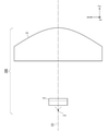
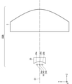
- FIG. 1 shows a view of the YZ plane observed from the ⁇ X axis side
- FIG. 2 shows a view of the ZX plane observed from the + Y axis direction side.
- the light source device 100 includes a light source group 1, a light deflection element 2, and a parallelizing lens 3, and a light deflection element 2 is arranged between the light source group 1 and the parallelizing lens 3. ing.
- the optical deflection element 2 is provided with optical planes 21 and 22 for optical deflection on the light emitting side, and the optical planes 21 and 22 are tilted together toward the optical axis C1 passing through the center of the parallelizing lens 3. ing.
- the light source group 1 has a light source 1a and a light source 1b arranged in the Y-axis direction as shown in FIG.
- the light source 1a and the light source 1b are solid-state light sources having different divergence angles in the X-axis direction and the divergence angle in the Y-axis direction, and are, for example, laser diodes.
- the XY planes of the light source 1a and the light source 1b are the light emitting surfaces
- the side in the Y-axis direction is longer than the side in the X-axis direction
- the divergence angle in the Y-axis direction (the angle in the ⁇ RX direction) is the divergence in the X-axis direction. It shall be smaller than the angle (angle in the ⁇ RY direction).
- the lengths of the light sources 1a and 1b in the Y-axis direction are 70 ⁇ m, and the length in the X-axis direction is 1 ⁇ m.
- the Y-axis direction having a small divergence angle is also referred to as a first direction
- the X-axis direction is also referred to as a second direction.
- FIG. 3 shows the light distribution characteristics of the light emitted from the light source 1a and the light source 1b.
- the vertical axis indicates the relative light intensity (arbitrary unit)
- the horizontal axis indicates the light divergence angle (°).
- the characteristic 301 shown by the solid line shows the light distribution characteristic of the light diverging in the X-axis direction ( ⁇ RY direction)
- the characteristic 302 shown by the alternate long and short dash line indicates the distribution of the light diverging in the Y-axis direction ( ⁇ RX direction). It shows the optical characteristics.
- the divergence angle in the Y-axis direction is smaller than the divergence angle in the X-axis direction.
- the broken line 303 indicates a position where the relative light intensity is 1 / e 2 , that is, a position where the relative light intensity is about 0.135.
- divergence angle generally laser diode, the relative light intensity to be displayed at an angle position at which the 1 / e 2 number, a measure of the light spread.
- the angle of the position of the characteristic 301 at 1 / e 2 is ⁇ about 37 °
- the angle of the position of the characteristic 302 at the position of 1 / e 2 is ⁇ about 5 °.
- the relative light intensity denote the angular range based on the location of the 1 / e 2.
- the light source 1a and the light source 1b emit, for example, red light having a center wavelength of 638 nm.
- the light source is red as compared with the light source that emits blue light having a center wavelength of, for example, 450 nm and the light source that emits green light having a center wavelength of, for example, 525 nm.
- the light source that emits light is highly sensitive to temperature, and when the temperature rises, the emission efficiency decreases and the wavelength shift occurs.
- the distance between the light sources 1a and the light source 1b that is, the distance in the arrangement direction, that is, the distance in the Y-axis direction in the present embodiment is wide.
- the light utilization efficiency on the optical axis C1 decreases. Therefore, in order to improve the light utilization efficiency, the light source 1a and the light source 1b are of the optical axis C1. It is preferably placed close to each other.
- FIG. 4 is a diagram showing an example of ray tracing.
- FIG. 4 shows an optical system composed of only the light source group 1 and the parallelizing lens 3, and also shows an enlarged view of the region “A” including the light source group 1 and the parallelizing lens 3.
- the light ray 401 emitted from the central portion of the light source 1a is shown by a solid line
- the light ray 402 emitted from the central portion of the light source 1b is shown by a alternate long and short dash line.
- the spread of each light ray in the Y-axis direction was set to ⁇ 5 ° as described with reference to FIG.
- the ray 401 and the ray 402 emitted from the parallelizing lens 3 gradually move away from the optical axis C1 in the arrangement direction of the light source, more specifically, the ray 401 travels in the ⁇ Y axis direction and the ray 402 travels in the + Y axis direction. It can be confirmed that it is.
- the light from the light source group 1 is separated from the optical axis C1 in the arrangement direction of the light sources, and the light utilization efficiency on the optical axis C1 is lowered.
- the array interval from the optical axis C1 to the emission position of each light source is the image height
- the shorter the focal length of the parallelizing lens 3 the higher the image height on the reaching surface, that is, at any position in the Z-axis direction.
- the light beam reaches a position away from the optical axis C1.
- the light beam emitted on the optical axis C1 reaches the vicinity of the optical axis C1 even on the arrival surface.
- the light rays have a width in the ⁇ Y-axis direction due to the influence of the divergence angle of the light source, the light rays parallel to the optical axis C1 also reach the reaching surface, and the width in the ⁇ Y-axis direction is defined. Considering that it has, it was set as "nearby".
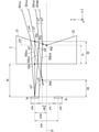
- FIG. 5 is a conceptual diagram illustrating the operation of the light deflection element 2, and the features of the light deflection element 2 will be described with reference to FIG.
- the light deflection element 2 By arranging the light deflection element 2 between the light source 1a and the parallelizing lens 3 (FIG. 1), the light ray 501cc emitted from the central portion of the light source 1a due to the deflection action of the light deflection element 2 is + Y with respect to the optical axis C1. It has an angle ⁇ 1 in the axial direction and can be incident on the parallelizing lens 3.
- a ray traveling in the + Z-axis direction at an angle ⁇ 1 is emitted as a ray parallel to the optical axis C1 by the parallelizing lens 3, so that a decrease in light utilization efficiency on the optical axis C1 can be suppressed.
- the length y1a in the Y-axis direction of the light source 1a is 70 ⁇ m
- the length y1b in the Y-axis direction of the light source 1b is 70 ⁇ m
- the central portion of the light source 1a and the optical axis C1 are in the Y-axis direction.
- the distance y1ac is 105 ⁇ m
- the distance y1c between the ⁇ Y-axis direction end of the light source 1a and the + Y-axis direction end of the light source 1b is 140 ⁇ m
- the distance y1d between the central portion of the light source 1a and the central portion of the light source 1b is 210 ⁇ m. ..
- the distance D1 between the light emitting surface of the light source 1a and the light source 1b and the light incident surface of the light deflection element 2 is 350 ⁇ m, and the thickness T1 of the minimum portion of the light deflection element 2 is 280 ⁇ m.
- the intersection of the light beam parallel to the optical axis C1 and the light incident surface of the optical deflection element 2 in the light emitted from the central portion of the light source 1a is P50
- the optical axis C1 of the light emitted from the central portion of the light source 1a is defined as P50.
- the distance D2 between P50 and P51 is about 315 ⁇ m.
- the material of the light deflection element 2 is, for example, BSC7 of HOYA Corporation, and the refractive index at a wavelength of 638 nm is about 1.515.
- the light ray 501cc is a light ray emitted from the central part of the light source 1a at an angle of 0 °, that is.
- the light ray 501cc emits the central portion of the light source 1a and is incident on the light deflection element 2 at an angle of 0 °. After reaching the emission surface of the light deflection element 2, it is refracted and travels in the + Z axis direction at an angle ⁇ 1.
- the angle ⁇ 1 is calculated by the following mathematical formula (1) using Snell's law. The angle is calculated as an absolute value.
- the incident light is refracted to an angle ⁇ 3 and travels to the emission surface of the light deflection element 2.
- the light travels in the + Z axis direction at an angle ⁇ 4.
- the angle ⁇ 3 is calculated by the following formula (3).
- the angle is calculated as an absolute value.
- the angle ⁇ 4 is calculated by the following formula (4).
- the angle is calculated as an absolute value.
- the incident light is refracted to an angle ⁇ 6 and travels to the emission surface of the light deflection element 2.
- the light On the emission surface of the light deflection element 2, after refraction, the light travels in the + Z axis direction at an angle ⁇ 7.
- the angle ⁇ 6 is calculated by the following formula (6).
- the angle is calculated as an absolute value.
- the angle ⁇ 7 is calculated by the following formula (7).
- the angle is calculated as an absolute value.
- the light ray 501dd preferably passes in the + Y-axis direction from the intersection P52 between the optical axis C1 and the emission surface of the optical deflection element 2.
- the light ray 501cd and the light ray 501dd are in a parallel relationship.
- the light from the light source 1b has a line-symmetrical relationship with the light from the light source 1a with respect to the optical axis C1.
- the light deflection element 2 is a light source arranged on the + side of the optical axis C1 in the arrangement direction of the light sources, and in the present embodiment, the light distribution direction + side (in the present embodiment) with respect to the light from the light source 1a.
- the apparent positions of the light source 1a and the light source 1b in the Y-axis direction can be moved in the optical axis C1 direction.
- the length of the entire apparent light source in the Y-axis direction can be shortened.
- the length y1p in the Y-axis direction of the position P54 is 21 ⁇ m, and the distance D3 between the light source 1a and the position P54 in the Z-axis direction is 214 ⁇ m. Since aberration is generated due to the influence of the light deflection element 2, the position P54 is an approximate position.
- the virtual image height which is the apparent image height of the light source 1a with respect to the optical axis C1. It is possible to set y1p to 21 ⁇ m. That is, the image height after the parallelizing lens 3 is emitted can be reduced to 1/5.
- the light deflection element 2 in this way, it is possible to reduce the apparent image height. This makes it possible to improve the light utilization efficiency in the vicinity of the optical axis C1.
- the angle ⁇ 1 that emits the light deflection element 2 of the light ray 501 cc emitted from the central portion of the light source 1a is preferably as small as possible in consideration of the miniaturization of the parallelizing lens 3 installed in the subsequent stage. Since the parallelizing lens 3 is circular when observed from the XY plane, it is assumed that when the light beam moves in the Y-axis direction, the divergence angle of the light source 1a in the X-axis direction ( ⁇ RY direction) is ⁇ 37 °. This is because there is a high possibility that the amount of light incident on the parallelizing lens 3 will decrease.
- the apparent light source position P54 is moved by 214 ⁇ m in the + Z axis direction from the actual light source position.
- the focal length of the parallelizing lens 3 it becomes necessary to shorten the focal length of the parallelizing lens 3 by 214 ⁇ m. Therefore, the light source image at the condensing position becomes slightly larger.
- the image height 2000 mm away from the parallelized lens 3 is an optical deflection element. It becomes 6.67 mm, which is slightly larger than 6.46 mm when there is no 2. That is, it becomes 1.03 times.
- the effect of such a magnification (1.03 times) is sufficiently smaller than the effect of lowering the image height, that is, the effect of reducing the image height to 1/5 times.
- the calculation formula is shown below.
- the image height 21 ⁇ m ⁇ 2000 mm / 6.5 mm ⁇ 6.46 mm.
- the image height 21 ⁇ m ⁇ 2000 mm / 6.3 mm ⁇ 6.67 mm.
- the distance between the ends of adjacent light sources is 140 ⁇ m, but the same effect can be obtained even if the distance y1c is 70 ⁇ m.
- the interval D1 can be set from 350 ⁇ m to 150 ⁇ m.
- the position of the light deflection element 2 so that the light ray traveling in the + Z-axis direction at an angle ⁇ 5 from the ⁇ Y-axis direction end of the light source 1a, that is, the light ray 501dd in FIG. 5 travels in the + Y-axis direction from P52.
- the length y1a of the light source 1a in the Y-axis direction becomes long
- the light beam traveling in the + Z-axis direction at an angle ⁇ 5 from the end in the ⁇ Y-axis direction of the light source 1a travels in the ⁇ Y-axis direction from P52.
- the interval D1 it is possible to lengthen the interval D1 by changing the material of the light deflection element 2 to a glass material or the like having a high refractive index.
- the angle ⁇ 8 is changed.
- the angle ⁇ 8 may be set so that the angle ⁇ 1 is 10.43 °, and specifically, the angle ⁇ 8 can be set to 12.5 °.
- the interval D1 can be set to 380 ⁇ m in consideration of the change in the back focus length due to the difference in the refractive index.
- the apparent Y-axis direction and Z-axis direction of the light source position P54 change. It becomes necessary to change the position and focus in the Z-axis direction of. If the interval D1, the thickness T1 of the minimum portion of the light deflection element 2, and the angle ⁇ 8 are set so that the apparent Y-axis direction and Z-axis direction positions of the light source position P54 do not change, the Z of the parallelizing lens 3 is set. Eliminates the need to change axial position and focus.
- the same function as that of the light deflection element 2 can be realized by using two mirrors.
- the mirror is tilted by ⁇ 10.43 / 2 ⁇ 5.22 ° with respect to the optical axis C1. More specifically, it is tilted by ⁇ 5.22 ° with respect to the light of the light source 1a arranged on the + Y-axis side and by +5.22 ° with respect to the light of the light source 1b arranged on the ⁇ Y-axis side.
- the divergence angle of the light source 1a is ⁇ 5 °
- a part of the light emitted at ⁇ 5 ° may reach the parallelizing lens 3 without reaching the mirror.
- the light source has a length in the Y-axis direction, which is the arrangement direction, so that the width of the mirror, that is, the length in the Z-axis direction must be longer than the distance to the parallelizing lens 3, the end of the light source,
- the light source 1a is arranged on the + Y-axis side, the light emitted from the end portion in the + Y-axis direction may not reach the mirror.
- FIG. 6 shows a schematic configuration when the light deflection element 2 is replaced by a mirror.
- the length y1a of the light source 1a in the Y-axis direction is 70 ⁇ m
- the distance y1ac in the Y-axis direction between the central portion of the light source 1a and the optical axis C1 is 105 ⁇ m, which is the same as the example of FIG.
- the angle ⁇ 2 and the angle ⁇ 5 are the same as in the example of FIG.
- the tilt angle ⁇ 9 of the mirror M was set to ⁇ 8 °.
- the ray corresponding to the ray 503cu is indicated by the ray 504cu
- the light rays in the ⁇ Z axis direction are represented by the light rays 504 uc, 504 uu, and 504 ud, it can be confirmed that the light rays 503 ud behave as if they are emitted from the light emitting point at the position P55u.
- the light ray 503dc emitted parallel to the optical axis C1
- the angle ⁇ 5 + 5 °.
- the light collecting efficiency of the light source 1a is improved by using the mirror M, the light collecting effect is highest when the following formula (9) is satisfied.
- the following is a conditional expression when the position P55c is on the optical axis C1.
- y1ac / D4 sin (2 ⁇
- the distance D4 between the central portion of the light source 1a and the reflection surface of the mirror M is about 381 ⁇ m.
- the mounting interval D4 allows, for example, an error of 381 ⁇ m ⁇ 10% (38 ⁇ m).
- the diameter of the parallelizing lens 3 can be increased, the substitution of the optical deflection element 2 by the mirror M is not excluded.
- the traveling direction of light can be changed from the + Z-axis direction to the ⁇ X-axis direction and the like. Therefore, by adjusting the inclination of the mirror M or the distances from the light source 1a and the light source 1b to the parallelized lens, in addition to the effect of suppressing the decrease in the light utilization efficiency on the optical axis, the degree of freedom in component arrangement is improved. can.
- the traveling direction of light is changed in the ⁇ X-axis direction
- the mirror surface is tilted in two axes, so the tendency of the emitted light rays changes depending on the center of rotation of the mirror.
- the light beam travels in the X-axis direction without maintaining the spread of the light ray before the reflection.
- the parallelizing lens 3 makes the light emitted from the light deflection element 2 parallel to the optical axis C1.
- the parallelizing lens 3 is formed, for example, in an aspherical shape.
- the aspherical shape can be a toroidal shape having different shapes in the X-axis direction and the Y-axis direction. Further, the light incident surface may have a convex shape or a concave shape.
- the light rays are parallel to the optical axis C1 with respect to the light rays emitted from the central portion of the light source 1a and the central portion of the light source 1b.
- the light rays emitted from the central portion of the light source 1a and the central portion of the light source 1b reach the vicinity of the optical axis C1, and the reached light source image can be minimized.
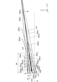
- FIG. 7 is a diagram showing a ray tracing result of a ray emitted from the light source 1a.
- an enlarged view of the region “B” including the light source group 1 and the light deflection element 2 and an enlarged view of the region “C” of the emission surface of the parallelizing lens 3 are shown together.
- the positional relationship between the light source 1a and the light deflection element 2 is as shown in FIG.
- the parallelizing lens 3 is arranged on the + Z axis direction side of the light deflection element 2.
- the focal length of the parallelizing lens is about 6.5 mm.
- a light ray having a spread of ⁇ 5 ° is emitted from the light source 1a in the + Z axis direction.
- the ray tracing results of the ray 601u emitted from the + Y-axis direction end of the light source 1a, the ray 601c emitted from the central portion of the light source 1a, and the ray 601d emitted from the ⁇ Y-axis direction end of the light source 1a are shown.
- the light rays 601u, the light rays 601c, and the light rays 601d emitted from the parallelizing lens 3 are substantially parallel to the optical axis C1.
- FIG. 8 is a diagram illustrating an inclination angle of a light ray actually emitted from the light source 1a with respect to the optical axis C1.
- the parallelizing lens 3 is a virtual thin-walled lens 703, and the focal length F7 is 6.5 mm. It is assumed that the light source 1a is moved so that the central portion of the light source 1a is located on the optical axis C1.
- FIG. 8 shows the behavior of the light rays 701u emitted from the + Y-axis direction end of the light source 1a and the light rays 701d emitted from the ⁇ Y-axis direction end of the light source 1a.
- the angle ⁇ u and the angle ⁇ d of the light ray 701u and the light ray 701d emitted from the thin-walled lens 703 with respect to the optical axis C1 are expressed by the following mathematical formula (10).
- the parallelizing lens 3 is emitted at an angle of 0.31 °, it can be assumed that the light source 1a is emitted from the optical axis C1.
- FIG. 9 shows the result of back light tracing using the configuration of FIG.
- an enlarged view of the region “D” including the light source group 1 and the light deflection element 2 and an enlarged view of the region “E” of the emission surface of the parallelizing lens 3 are shown together.
- the above assumption is confirmed by tracking the back rays of the light rays traveling from the + Z axis direction to the ⁇ Z axis direction of the parallelizing lens 3 and confirming the image formation position.
- FIG. 9 shows the back ray tracing results of the ray 801u, the ray 801c, and the ray 801d, and the ray 801d is incident on the collimated beam 3 at an angle of ⁇ 0.31 ° with respect to the optical axis C1.
- the light ray 801c is incident on the parallelizing lens 3 in parallel with the optical axis C1
- the light ray 801u is incident on the parallelizing lens 3 at an angle of +0.31 ° with respect to the optical axis C1.
- the light rays 801u are focused (imaged) on the + Y-axis direction end of the light source 1a, and the light rays 801c are focused (imaged) on the center of the light source 1a, and the light rays 801d.
- the light ray 801c is an example of condensing light on the central portion of the light source 1a in the Y-axis direction, but the parallelizing lens 3 and the optical deflection when parallel light is incident from the + Z-axis direction side of the parallelizing lens 3.
- the condensing position of the parallel light by the optical system including the element 2 does not have to be exactly located on the light emitting surface of each of the light source 1a and the light source 1b.
- the central portions of the light source 1a and the light source 1b are within ⁇ y1a / 3 from the center in the Y-axis direction and ⁇ 30 ⁇ m from the light emitting surface of the light source 1a in the Z-axis direction. It may preferably contain ⁇ 10 ⁇ m or less.
- the position in the Y-axis direction of the position P54 is the image height position of the light source 1a, but in FIG. 9, the behavior of the light ray such that the central portion of the light source 1a is located on the optical axis C1. I am doing.
- the shape of the parallelizing lens 3 is set so that the light rays are concentrated at the position P54 when the light rays parallel to the optical axis C1 are incident on the parallelizing lens 3 from the + Z axis direction.
- the focal position of the parallelizing lens 3 is in the ⁇ Z axis direction from the position P54, but it is possible to make the optical axis C1 behave as a light ray in which the central portion of the light source 1a is arranged.
- FIG. 10 is a diagram showing a back light ray tracking result when a light ray parallel to the optical axis C1 is incident from the + Z axis direction of the parallelizing lens 3.
- FIG. 10 an enlarged view of the region “F” including the light source group 1 is also shown.
- the focusing point P80 of the parallelizing lens 3 is on the + Z axis direction side from the light source 1a and on the + Y axis direction side from the optical axis C1.
- the focal position P80f of the parallelizing lens 3 is on the ⁇ Z axis direction side from the focusing point P80.
- the focal position P80f is located on the + Z axis side of the light source 1a because the back focus of the parallelizing lens 3 is shortened due to the influence of the optical deflection element 2 which is an optical element. It is also considered that the angle ⁇ 1 is affected by the deflection of the light beam.
- the distance between the focusing point P80 and the focal position P80f in the Z-axis direction is about 140 ⁇ m.
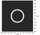
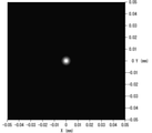
- FIG. 10 the illuminance distributions on the condensing point P80 and the focal position P80f when the parallel light flux is incident on the + Z axis side of the parallelizing lens 3 in the ⁇ Z axis direction are shown in FIGS. 11 and 12, respectively.
- the X-axis (mm) is shown on the horizontal axis and the Y-axis (mm) is shown on the vertical axis, and the light intensity is divided into five gradations. The brightest white color represents 100% intensity.
- FIG. 11 it can be seen that a ring-shaped illuminance distribution with a hollow center is formed on the condensing point P80, and the intensity is strong in the vicinity of a region having a radius of 20 ⁇ m.
- FIG. 12 it can be seen that on the focal position P80f, a concentric illuminance distribution is formed and a small condensing spot is formed to be the focal position.
- the optical surfaces 21 and 22 for light deflection are provided on the light emitting side of the light deflection element 2, but there is also a case where the optical surfaces 21 and 22 for light deflection are provided on the light incident side.
- a similar effect can be obtained. It should be noted that the effect of improving the light utilization efficiency on the optical axis C1 can be obtained without forming a ring-shaped region having a strong light intensity. Further, even in the configuration using the mirror M shown in FIG. 6, a ring-shaped illuminance distribution can be formed.
- FIG. 13 shows the result of back light tracing of the configuration using the mirror M shown in FIG.
- an enlarged view of the region “G” including the light source group 1 and the mirror M and an enlarged view of the region “F” of the emission surface of the parallelizing lens 3 are shown together.
- FIG. 13 shows the back ray tracing result when the ray 1101u, the ray 1101c, and the ray 1101d are incident from the + Z axis direction of the parallelizing lens 3.
- the ray 1101u is incident on the parallelizing lens 3 at an angle ⁇ 0.31 ° with respect to the optical axis C1
- the ray 1101c is incident on the parallelizing lens 3 parallel to the optical axis C1
- the ray 1101d is emitted.
- It is incident on the parallelizing lens 3 at an angle of +0.31 ° with respect to the optical axis C1.
- the light ray 1101u is focused (imaged) on the + Y-axis end of the light source 1a
- the light ray 1101c is focused (imaged) on the center of the light source 1a
- the light ray 1101d is focused on the light source 1a. It can be seen that the light source is focused (imaging) at the end in the Y-axis direction.
- the light ray 1101u is focused in the ⁇ Z axis direction as compared with the light collecting position of the light ray 1101c.
- the light ray 1101d is focused in the + Z axis direction as compared with the light collecting position of the light ray 1101c. That is, since the condensing position in the Y-axis direction shifts in the Z-axis direction as compared with the case where the light deflection element 2 is used, in the light beam emitted from the light source 1a, at an arbitrary reaching surface after the parallelizing lens 3 is emitted. It can be seen that the light beam width of is non-uniform in the Y-axis direction.
- FIG. 9 which is the result of back light tracing using the configuration of FIG. 5, and FIG. 13 which is the result of back light tracking using the configuration of FIG. 6, the evaluation surface (XY plane) at a distance of 2000 mm from the light source 1a.
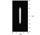
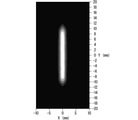
- 14 to 16 show the illuminance distribution of the light emitted from the light source 1a. From FIG. 3, the divergence angle of the light source 1a is ⁇ about 37 ° for 1 / e 2 in the X-axis direction (RY direction) and ⁇ about 5 ° for 1 / e 2 in the Y-axis direction (RX direction). ..
- FIGS. 14 to 16 an X-axis (mm) is shown on the horizontal axis and a Y-axis (mm) is shown on the vertical axis, and the light intensity is divided into five gradations. The brightest white color represents 100% intensity.
- FIG. 14 shows the illuminance distribution of light when the light deflection element 2 is used
- FIG. 15 shows the light illuminance distribution when the mirror M is used. From FIG. 14, when the light axis C1 is 0 mm in the Y-axis direction, the region where the light intensity is 80% (80% when the maximum light intensity is 100%) or more is continuously 8.4 mm to + 10.1 mm ( It can be seen that the light reaches the range of 18.5 mm) uniformly. Further, it can be seen that the region where the light intensity is 20% or more with the maximum light intensity as 100% is in the range of -10.3 mm to +12.3 mm (22.6 mm). From this, the ratio of the range in the Y-axis direction of the uniform region of 80% or more to the region of light intensity of 20% or more is about 81.9% (18.5 mm / 22.6 mm).
- the image height of the light source 1a is as follows. It is expressed by the formula (11).
- the illuminance range in the Y-axis direction is slightly less than +10.7 mm on the + side from the region of light intensity of 20% or more, but is within -10.7 mm on the-side. Further, the region of light intensity of 80% or more is within ⁇ 10.7 mm, and considering the ratio of the region of light intensity of 80% to the region of light intensity of 20% or more in the Y-axis direction, the optical axis C1 It is considered that almost the same result as the case where the light source 1a is on the top is obtained.
- the illuminance distribution in the Y-axis direction has a region of light intensity of 80% or more in the range of -9.3 mm to -6.9 mm (2.4 mm) in the Y-axis direction. It can be seen that the region with high light intensity is located at a position away from the optical axis C1. Further, since the range of the light intensity region of 80% or more is narrow, it can be seen that the light having a strong light intensity is concentrated. Further, it can be seen that the light intensity of 20% or more is in the range of -10.2 mm to + 12.8 mm (22.8 mm).
- the light intensity of 40% or more is within the range of ⁇ 10.7 mm, it is considered that the light intensity is generally within ⁇ 10.7 mm.
- the light intensity on the optical axis C1 is lower than the peak position, and the apparent light source 1a is tilted. Conceivable.
- FIG. 16 is a diagram showing an illuminance distribution in the case of the configuration of FIG. 4 in which the light deflection element 2 and the mirror M are not arranged as a comparative example.
- the light intensity region of 20% or more is almost uniformly in the range of ⁇ 42.7 mm to -20.7 mm (22.0 mm).
- FIGS. 17 to 19 show the illuminance distribution of the light on the evaluation surface at a distance of 2000 mm from the light source 1a and the light source 1b when both the light source 1a and the light source 1b are turned on.
- the divergence angle of the light source 1a and the light source 1b are both from FIG. 3, 1 / e 2 is approximately ⁇ 37 ° in the X-axis direction (RY direction), 1 / e 2 of the Y-axis direction (RX direction) ⁇ It was set to about 5 °.
- an X-axis (mm) is shown on the horizontal axis and a Y-axis (mm) is shown on the vertical axis, and the light intensity is divided into five gradations. The brightest white color represents 100% intensity.
- FIG. 17 shows the illuminance distribution when the light deflection element 2 is used
- FIG. 18 shows the illuminance distribution when the mirror M is used
- FIG. 19 shows the illuminance distribution when the focal position of the parallelizing lens 3 is moved by 15 ⁇ m in the + Z axis direction using the mirror M. Shows.
- the region where the light intensity is 80% or more is continuously illuminated uniformly in the range of -8.9 mm to +8.9 mm (17.8 mm).
- the region where the light intensity is 20% or more is in the range of -11.5 mm to +11.6 mm (23.1 mm).
- the ratio of the range in the Y-axis direction of the uniform region of 80% or more to the region of light intensity of 20% or more is about 77.1% (17.8 mm / 23.1 mm). That is, it can be seen that the light intensity is uniformly distributed in the range of about 77.1% without peak peaks.
- the region where the light intensity is 80% or more is in the range of -2.7 mm to +2.7 mm (5.4 mm). Further, it can be seen that the region where the light intensity is 20% or more is in the range of -10.8 mm to +10.7 mm (21.5 mm). From this, the ratio of the range in the Y-axis direction of the region having a high light intensity of 80% or more to the region having a light intensity of 20% or more is about 25.1% (5.4 mm / 21.5 mm). That is, it can be seen that the region having a light intensity of 80% or more is concentrated in the range of about 25.1%, and the light utilization efficiency on the optical axis C1 is high.
- the light intensity on the optical axis C1 is increased, and the light utilization efficiency in the optical axis C1 direction can be improved as compared with the case of FIG.
- the design of the parallelizing lens 3 is devised so that the light beam 1101u traced by the back light beam is focused near the + Y-axis direction end face of the light source 1a shown in FIG. 13, so that the light utilization efficiency in the optical axis C1 direction is achieved. It means that it is possible to improve.
- the fact that the light beam 1101u traced by the back ray focuses on the vicinity of the + Y-axis direction end face of the light source 1a means that the focusing position (focus position of the parallelizing lens 3) in FIG. 13 moves in the + Z-axis direction. Means.
- FIG. 19 is an example in which the focal position of the parallelizing lens 3 is moved by 15 ⁇ m in the + Z axis direction using the mirror M, the configuration for the light utilization efficiency on the optical axis C1 corresponding to or higher in FIG. 18 is parallel.
- the focal position of the modified lens 3 may be moved by 15 ⁇ m ⁇ 15 ⁇ m in the + Z axis direction.
- FIG. 19 when the width in the Y-axis direction is confirmed in the region where the light intensity is 80% or more, FIG. 19 is 5.4 mm ( ⁇ 2.7 mm) and FIG. 17 is 17.8 mm ( ⁇ 8.9 mm). Therefore, FIG. 19 using the mirror M, which is a reflection type light deflection element, has higher light utilization efficiency on the optical axis C1 than FIG. 17 using the transmission type light deflection element 2. In FIG. 17, since there is no light loss due to the reflectance of the mirror M, the light utilization efficiency is high as a whole, and the light utilization efficiency on the evaluation surface is high.
- the ratio of the range in the Y-axis direction of the region where the light intensity is 80% or more to the region where the light intensity is 20% or more is 75% or more. It is possible to collect uniform light on the optical axis C1 while increasing the light utilization efficiency on the optical axis C1.
- a light intensity uniform element for example, a rod lens and a light pipe
- the number of reflections in the element can be reduced, so that the size (length) of the optical system can be shortened.
- the ratio of the range in the Y-axis direction of the region having a high light intensity of 80% or more to the region having a light intensity of 20% or more is set to 30% or less. This makes it possible to further improve the light utilization efficiency on the optical axis C1.
- the aperture size of a light intensity uniform element for example, a rod lens and a light pipe, is small, it can be incorporated into an optical system with high light utilization efficiency.
- an example of an optical system including a appropriately designed mirror M includes an optical system in which the focal position of the parallelizing lens 3 is adjusted as described above.
- Examples of the method for adjusting the focal position of the parallelizing lens 3 include a method of moving the parallelizing lens 3 in the + Z axis direction or a method of moving the light source group in the ⁇ Z axis direction.
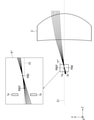
- FIG. 20 is a diagram showing a schematic configuration of a light source device 100A which is a modification of the light source device 100.
- the number of light sources can be three or more.
- a light source 14c third is further placed on the optical axis C1.
- Light source is arranged.
- the light deflection element 20 as shown in FIG. 20 can be used.
- the 20 has a first optical surface 20c having no inclination with respect to a reference plane (XY plane) perpendicular to the optical axis C1 on the optical axis C1, and both sides thereof with respect to a reference plane. It includes a second optical surface 20a and a third optical surface 20b having an inclination.
- the first optical surface 20c emits light rays emitted from the light source 14c from the optical deflection element 20 at the same angle in the + Z axis direction.
- the second optical surface 20a emits a light ray emitted from the light source 14a in the + Z-axis direction at an angle in the + Y-axis direction as in the light ray 501cc in FIG. 5, for example.
- the third optical surface 20b emits a light ray emitted from the light source 14b at an angle in the ⁇ Y axis direction in the + Z axis direction.
- the second optical surface 20a causes the virtual focusing point of the light source 14a to move in the + Z-axis direction
- the third optical surface 20b causes the virtual focusing point of the light source 14b to move in the + Z-axis direction. Moving. Therefore, the following adjustment may be made so as to align the position in the Z-axis direction with the virtual condensing points of both. That is, the first optical surface 20c may be moved in the + Z axis direction to adjust the air conversion length. Further, the light source 14c may be moved in the + Z axis direction.
- FIG. 20 shows an example in which an optical surface for light deflection is arranged on the light incident side, it is also possible to provide the optical surface on the light emitting side. By adopting such a configuration, it is possible to further improve the light utilization efficiency in the vicinity of the optical axis C1.
- the same deflection function by using a mirror.
- no mirror is provided in the portion corresponding to the first optical surface 20c having no inclination, and the second optical surface 20a and the third optical surface 20a and the third optical surface 20a are not provided.
- a mirror will be provided on the portion corresponding to the optical surface 20b of the above.
- the light source 14c may be moved in the + Z-axis direction so as to match the positions of the virtual condensing points of the light source 14a and the light source 14b in the Z-axis direction.
- the "light deflection element" in a broad sense is a member that adjusts the length of the entire apparent light source in the Y-axis direction in the arrangement direction of the light source by deflecting the light by using reflection (this example). Then, the above mirror) is also included.
- a configuration in which the number of light sources is two or more is preferable.
Abstract
A light source device according to the present disclosure comprises: a collimating lens that collimates incident light; a light source group that includes a plurality of light sources disposed apart from one another in a direction separating away from the optical axis of the collimating lens and that overall emits a beam of light having a divergence angle which differs in a first direction and a second direction, the first direction and the second direction being perpendicular to one another and being each parallel to a direction separating away from the optical axis; and a light deflecting element that is disposed between the light source group and the collimating lens in the optical axis direction and that deflects the light emitted from each of the plurality of light sources in a direction separating away from the optical axis to cause the light to be incident on the collimating lens in the first direction, in which the divergence angle of the light source group is smaller from among the first direction and the second direction.
Description
本開示は光源装置に関し、特に光利用効率を高めた光源装置に関する。
This disclosure relates to a light source device, and particularly to a light source device having improved light utilization efficiency.
投射型表示装置等に用いられる固体光源において、高出力化と結合効率の向上が課題となっている。例えば、特許文献1には、複数の発光点を備える光源と、光源からの出射光を平行化するコリメートレンズと、主面に対して異なる傾斜角を有し、かつ複数の出射光それぞれに対する複数の入射面を有する光学素子と、で構成された光源ユニットが開示されている。特許文献1には、特に、光源ユニットの小型化を実現するために、光学素子が、入射面を備えたミラーを複数有する構成が図16等に開示されている。
In solid-state light sources used in projection-type display devices, high output and improvement of coupling efficiency have become issues. For example, Patent Document 1 describes a light source having a plurality of light emitting points, a collimating lens that parallelizes the emitted light from the light source, and a plurality of light sources having different inclination angles with respect to the main surface and for each of the plurality of emitted light. A light source unit composed of an optical element having an incident surface of the above is disclosed. Patent Document 1 discloses, in particular, a configuration in which an optical element has a plurality of mirrors provided with an incident surface in order to realize miniaturization of a light source unit.
特許文献1のようにミラーを利用した構成では、コリメートレンズから出射される平行化後の光線の光量分布が光軸に対して不均一となると、光軸上の光利用効率が低下してしまうなどの課題が生じるが、特許文献1では光源が見かけ上傾くことによる光軸上の光利用効率の低下等に関して何ら考慮されていない。
In the configuration using a mirror as in Patent Document 1, if the light amount distribution of the parallelized light rays emitted from the collimating lens becomes non-uniform with respect to the optical axis, the light utilization efficiency on the optical axis decreases. However, Patent Document 1 does not consider the decrease in light utilization efficiency on the optical axis due to the apparent tilt of the light source.
本開示は上記のような問題を解決するためになされたものであり、光軸上の光利用効率を高めた光源装置を提供することを目的とする。
The present disclosure has been made to solve the above problems, and an object of the present disclosure is to provide a light source device having improved light utilization efficiency on the optical axis.
本開示に係る光源装置は、入射光を平行化する平行化レンズと、前記平行化レンズの光軸から離れる方向に互いに離間して配置される複数の光源を含み、全体として互いに直交する前記光軸から離れる方向に平行な第1の方向と第2の方向とで発散角が異なる光束を発する光源群と、前記光軸の方向において前記光源群と前記平行化レンズとの間に配置され、前記第1の方向および前記第2の方向のうち、前記光源群の前記発散角が小さい前記第1の方向において、前記複数の光源の各々から発せられた光を前記光軸から離れる方向に偏向して前記平行化レンズに入射させる光偏向素子と、を備えている。
The light source device according to the present disclosure includes a parallelizing lens for parallelizing incident light and a plurality of light sources arranged apart from each other in a direction away from the optical axis of the parallelizing lens, and the light as a whole is orthogonal to each other. A group of light sources that emit light sources having different divergence angles in the first direction and the second direction parallel to the direction away from the axis are arranged between the light source group and the parallelizing lens in the direction of the optical axis. Of the first direction and the second direction, in the first direction in which the divergence angle of the light source group is small, the light emitted from each of the plurality of light sources is deflected in a direction away from the optical axis. It is provided with a light deflection element for incident on the parallelizing lens.
本開示の光源装置によれば、光軸上の光利用効率が高い光源装置を提供できる。
According to the light source device of the present disclosure, it is possible to provide a light source device having high light utilization efficiency on the optical axis.
<実施の形態1>
図1および図2を用いて実施の形態1の光源装置100の概略構成を説明する。図1はYZ平面を-X軸側から観察した図を示し、図2はZX平面を+Y軸方向側から観察した図を示している。図1および図2に示されるように光源装置100は、光源群1、光偏向素子2および平行化レンズ3を備え、光源群1と平行化レンズ3との間に光偏向素子2が配置されている。光偏向素子2は、光偏向用の光学面21および22が光出射側に設けられており、当該光学面21および22は、平行化レンズ3の中心を通る光軸C1に向けて共に傾斜している。光源群1は、図1に示されるようにY軸方向に配列された光源1aおよび光源1bを有している。 <Embodiment 1>
A schematic configuration of thelight source device 100 of the first embodiment will be described with reference to FIGS. 1 and 2. FIG. 1 shows a view of the YZ plane observed from the −X axis side, and FIG. 2 shows a view of the ZX plane observed from the + Y axis direction side. As shown in FIGS. 1 and 2, the light source device 100 includes a light source group 1, a light deflection element 2, and a parallelizing lens 3, and a light deflection element 2 is arranged between the light source group 1 and the parallelizing lens 3. ing. The optical deflection element 2 is provided with optical planes 21 and 22 for optical deflection on the light emitting side, and the optical planes 21 and 22 are tilted together toward the optical axis C1 passing through the center of the parallelizing lens 3. ing. The light source group 1 has a light source 1a and a light source 1b arranged in the Y-axis direction as shown in FIG.
図1および図2を用いて実施の形態1の光源装置100の概略構成を説明する。図1はYZ平面を-X軸側から観察した図を示し、図2はZX平面を+Y軸方向側から観察した図を示している。図1および図2に示されるように光源装置100は、光源群1、光偏向素子2および平行化レンズ3を備え、光源群1と平行化レンズ3との間に光偏向素子2が配置されている。光偏向素子2は、光偏向用の光学面21および22が光出射側に設けられており、当該光学面21および22は、平行化レンズ3の中心を通る光軸C1に向けて共に傾斜している。光源群1は、図1に示されるようにY軸方向に配列された光源1aおよび光源1bを有している。 <
A schematic configuration of the
<座標の設定>
本実施の形態では、説明を容易にするために、以下に示す図においてXYZ座標を用い、+Z軸方向に光が進行するものとする。また、X軸中心の右回りの回転を+RX、Y軸中心の右回りの回転を+RY、Z軸中心の右回りの回転を+RZとする。 <Coordinate setting>
In the present embodiment, in order to facilitate the explanation, it is assumed that the light travels in the + Z axis direction using the XYZ coordinates in the figure shown below. Further, the clockwise rotation at the center of the X axis is + RX, the clockwise rotation at the center of the Y axis is + RY, and the clockwise rotation at the center of the Z axis is + RZ.
<光源1a、光源1b>
光源1aおよび光源1bはX軸方向の発散角とY軸方向の発散角が異なる固体光源であり、例えば、レーザーダイオードである。ここで、光源1aおよび光源1bのXY平面を発光面とし、Y軸方向の辺がX軸方向の辺より長く、Y軸方向の発散角(±RX方向の角度)は、X軸方向の発散角(±RY方向の角度)より小さいものとする。例えば、光源1aおよび1bのY軸方向の長さは70μmであり、X軸方向の長さは1μmである。以下、発散角の小さいY軸方向を第1の方向、X軸方向を第2の方向とも呼ぶ。 <Light source 1a, light source 1b>
Thelight source 1a and the light source 1b are solid-state light sources having different divergence angles in the X-axis direction and the divergence angle in the Y-axis direction, and are, for example, laser diodes. Here, the XY planes of the light source 1a and the light source 1b are the light emitting surfaces, the side in the Y-axis direction is longer than the side in the X-axis direction, and the divergence angle in the Y-axis direction (the angle in the ± RX direction) is the divergence in the X-axis direction. It shall be smaller than the angle (angle in the ± RY direction). For example, the lengths of the light sources 1a and 1b in the Y-axis direction are 70 μm, and the length in the X-axis direction is 1 μm. Hereinafter, the Y-axis direction having a small divergence angle is also referred to as a first direction, and the X-axis direction is also referred to as a second direction.
光源1aおよび光源1bはX軸方向の発散角とY軸方向の発散角が異なる固体光源であり、例えば、レーザーダイオードである。ここで、光源1aおよび光源1bのXY平面を発光面とし、Y軸方向の辺がX軸方向の辺より長く、Y軸方向の発散角(±RX方向の角度)は、X軸方向の発散角(±RY方向の角度)より小さいものとする。例えば、光源1aおよび1bのY軸方向の長さは70μmであり、X軸方向の長さは1μmである。以下、発散角の小さいY軸方向を第1の方向、X軸方向を第2の方向とも呼ぶ。 <
The
<光源1a、光源1bの配光特性>
光源1aおよび光源1bから出射される光の配光特性を図3に示す。図3において縦軸は相対光強度(任意単位)を示し、横軸は、光の発散角度(°)を示す。実線で示す特性301は、X軸方向(±RY方向)に発散する光の配光特性を示しており、一点鎖線で示す特性302は、Y軸方向(±RX方向)に発散する光の配光特性を示している。上述したように、Y軸方向の発散角は、X軸方向の発散角よりも小さい。 <Light distribution characteristics oflight source 1a and light source 1b>
FIG. 3 shows the light distribution characteristics of the light emitted from thelight source 1a and the light source 1b. In FIG. 3, the vertical axis indicates the relative light intensity (arbitrary unit), and the horizontal axis indicates the light divergence angle (°). The characteristic 301 shown by the solid line shows the light distribution characteristic of the light diverging in the X-axis direction (± RY direction), and the characteristic 302 shown by the alternate long and short dash line indicates the distribution of the light diverging in the Y-axis direction (± RX direction). It shows the optical characteristics. As described above, the divergence angle in the Y-axis direction is smaller than the divergence angle in the X-axis direction.
光源1aおよび光源1bから出射される光の配光特性を図3に示す。図3において縦軸は相対光強度(任意単位)を示し、横軸は、光の発散角度(°)を示す。実線で示す特性301は、X軸方向(±RY方向)に発散する光の配光特性を示しており、一点鎖線で示す特性302は、Y軸方向(±RX方向)に発散する光の配光特性を示している。上述したように、Y軸方向の発散角は、X軸方向の発散角よりも小さい。 <Light distribution characteristics of
FIG. 3 shows the light distribution characteristics of the light emitted from the
なお、破線303は相対光強度が1/e2となる位置、つまり相対光強度が約0.135の位置を示している。一般的にレーザーダイオードの発散角の仕様は、相対光強度が1/e2となる位置の角度で表示することが多く、光の拡がりの目安となる。ここでは、特性301の1/e2となる位置の角度は±約37°、特性302の1/e2となる位置の角度は±約5°となる。以降、光源1aおよび光源1bの発散角の範囲といった場合、相対光強度が1/e2となる位置を基準とした角度範囲を示すものとする。
The broken line 303 indicates a position where the relative light intensity is 1 / e 2 , that is, a position where the relative light intensity is about 0.135. Specifications divergence angle generally laser diode, the relative light intensity to be displayed at an angle position at which the 1 / e 2 number, a measure of the light spread. Here, the angle of the position of the characteristic 301 at 1 / e 2 is ± about 37 °, and the angle of the position of the characteristic 302 at the position of 1 / e 2 is ± about 5 °. Later, if such a range of divergence angle of the light source 1a and the light source 1b, the relative light intensity denote the angular range based on the location of the 1 / e 2.
<光源1aと光源1bの間隔>
光源1aおよび光源1bは、例えば、中心波長638nmの赤色の光を発する。複数の光源を隣接配置して高出力化を行う際に、中心波長が例えば、450nmの青色の光を発する光源および中心波長が例えば、525nmの緑色の光を発する光源と比較して、赤色の光を発する光源は、温度に対して感度が高く、温度が高くなると発光効率の低下および波長シフトが発生する。従って、冷却を考慮すると、光源1aと光源1bの配列間隔、すなわち配列方向の間隔、本実施の形態ではY軸方向の間隔は、広い方が好ましい。しかし、一般的に光源1aと光源1bの配列間隔が拡がるに従って、光軸C1上の光利用効率が低下するため、光利用効率を向上させるためには、光源1aおよび光源1bは光軸C1の近くに配置されることが好ましい。 <Spacing betweenlight source 1a and light source 1b>
Thelight source 1a and the light source 1b emit, for example, red light having a center wavelength of 638 nm. When a plurality of light sources are arranged adjacent to each other to increase the output, the light source is red as compared with the light source that emits blue light having a center wavelength of, for example, 450 nm and the light source that emits green light having a center wavelength of, for example, 525 nm. The light source that emits light is highly sensitive to temperature, and when the temperature rises, the emission efficiency decreases and the wavelength shift occurs. Therefore, in consideration of cooling, it is preferable that the distance between the light sources 1a and the light source 1b, that is, the distance in the arrangement direction, that is, the distance in the Y-axis direction in the present embodiment is wide. However, in general, as the arrangement spacing between the light source 1a and the light source 1b increases, the light utilization efficiency on the optical axis C1 decreases. Therefore, in order to improve the light utilization efficiency, the light source 1a and the light source 1b are of the optical axis C1. It is preferably placed close to each other.
光源1aおよび光源1bは、例えば、中心波長638nmの赤色の光を発する。複数の光源を隣接配置して高出力化を行う際に、中心波長が例えば、450nmの青色の光を発する光源および中心波長が例えば、525nmの緑色の光を発する光源と比較して、赤色の光を発する光源は、温度に対して感度が高く、温度が高くなると発光効率の低下および波長シフトが発生する。従って、冷却を考慮すると、光源1aと光源1bの配列間隔、すなわち配列方向の間隔、本実施の形態ではY軸方向の間隔は、広い方が好ましい。しかし、一般的に光源1aと光源1bの配列間隔が拡がるに従って、光軸C1上の光利用効率が低下するため、光利用効率を向上させるためには、光源1aおよび光源1bは光軸C1の近くに配置されることが好ましい。 <Spacing between
The
<光源1aと光源1bの間隔と光利用効率との関係>
光偏向素子2を配置しない場合、つまり、光源群1と平行化レンズ3のみの場合、光源1aから出射した光と光源1bから出射した光は、平行化レンズ3で屈折後、光軸C1を境に徐々に離れていく。そのため、平行化レンズ3の後段で集光レンズを配置し、複数の光源装置100から出射した光を光軸C1上に集光する際に、集光レンズの光軸C1上に集光する光の効率が低くなる。 <Relationship between the distance between thelight source 1a and the light source 1b and the light utilization efficiency>
When thelight deflection element 2 is not arranged, that is, when only the light source group 1 and the parallelizing lens 3 are used, the light emitted from the light source 1a and the light emitted from the light source 1b are refracted by the parallelizing lens 3 and then set on the optical axis C1. Gradually move away from the border. Therefore, when a condenser lens is arranged after the parallelizing lens 3 and the light emitted from the plurality of light source devices 100 is focused on the optical axis C1, the light focused on the optical axis C1 of the condenser lens. Is less efficient.
光偏向素子2を配置しない場合、つまり、光源群1と平行化レンズ3のみの場合、光源1aから出射した光と光源1bから出射した光は、平行化レンズ3で屈折後、光軸C1を境に徐々に離れていく。そのため、平行化レンズ3の後段で集光レンズを配置し、複数の光源装置100から出射した光を光軸C1上に集光する際に、集光レンズの光軸C1上に集光する光の効率が低くなる。 <Relationship between the distance between the
When the
図4は、光線追跡の一例を示す図である。図4においては光源群1および平行化レンズ3のみで構成される光学系を示しており、光源群1および平行化レンズ3を含む領域“A”の拡大図を併せて示している。
FIG. 4 is a diagram showing an example of ray tracing. FIG. 4 shows an optical system composed of only the light source group 1 and the parallelizing lens 3, and also shows an enlarged view of the region “A” including the light source group 1 and the parallelizing lens 3.
図4に示されるように、光源1aの中央部から出射した光線401を実線で、光源1bの中央部から出射した光線402を一点鎖線で示す。なお、各光線のY軸方向の拡がりは、図3を用いて説明したように±5°とした。平行化レンズ3を出射した光線401および光線402は光源の配列方向において、徐々に光軸C1から離れる方向、より具体的には光線401は-Y軸方向、光線402は+Y軸方向に進行していることが確認できる。これにより、光源の配列方向において、光源群1からの光は光軸C1から離れていくこととなり、光軸C1上の光利用効率が低下することとなる。ここで、光軸C1から各光源の出射位置までの配列間隔を像高とすると、平行化レンズ3の焦点距離が短くなるほど、到達面、すなわち任意のZ軸方向位置での像高が高くなり、光軸C1から離れた位置に光線が到達することとなる。一方、光軸C1上を出射した光線は到達面でも光軸C1付近に到達する。ここで、付近とは、光源の発散角の影響により光線が±Y軸方向に幅を有するため、到達面には光軸C1と平行な光線も到達することとなり、±Y軸方向の幅を有することを鑑みて「付近」とした。
As shown in FIG. 4, the light ray 401 emitted from the central portion of the light source 1a is shown by a solid line, and the light ray 402 emitted from the central portion of the light source 1b is shown by a alternate long and short dash line. The spread of each light ray in the Y-axis direction was set to ± 5 ° as described with reference to FIG. The ray 401 and the ray 402 emitted from the parallelizing lens 3 gradually move away from the optical axis C1 in the arrangement direction of the light source, more specifically, the ray 401 travels in the −Y axis direction and the ray 402 travels in the + Y axis direction. It can be confirmed that it is. As a result, the light from the light source group 1 is separated from the optical axis C1 in the arrangement direction of the light sources, and the light utilization efficiency on the optical axis C1 is lowered. Here, assuming that the array interval from the optical axis C1 to the emission position of each light source is the image height, the shorter the focal length of the parallelizing lens 3, the higher the image height on the reaching surface, that is, at any position in the Z-axis direction. , The light beam reaches a position away from the optical axis C1. On the other hand, the light beam emitted on the optical axis C1 reaches the vicinity of the optical axis C1 even on the arrival surface. Here, in the vicinity, since the light rays have a width in the ± Y-axis direction due to the influence of the divergence angle of the light source, the light rays parallel to the optical axis C1 also reach the reaching surface, and the width in the ± Y-axis direction is defined. Considering that it has, it was set as "nearby".
<光偏向素子>
図5は光偏向素子2の作用を説明する概念図であり、図5を用いて光偏向素子2の特徴を説明する。光偏向素子2を光源1aと平行化レンズ3(図1)の間に配置することによって、光偏向素子2の偏向作用により光源1aの中央部から出射した光線501ccが光軸C1に対して+Y軸方向に角度α1を有して平行化レンズ3に入射させることが可能となる。角度α1で+Z軸方向に進行した光線が平行化レンズ3で光軸C1に対して平行な光線となって出射することにより、光軸C1上の光利用効率の低下を抑制できる。光源1bに対しても光軸C1を線対称にして同様に作用する。すなわち、光偏向素子2を配置することによって、光源1aおよび光源1bの中央部から出射した光軸C1と平行な光線を、屈折後に+Y軸方向および-Y軸方向に偏向させることにより、光軸C1から±Y軸方向に離れて配置された光源を光軸C1上あるいは、光軸C1方向に平行移動した位置に配置されたかのような振る舞いをさせることが可能となる。 <Light deflection element>
FIG. 5 is a conceptual diagram illustrating the operation of thelight deflection element 2, and the features of the light deflection element 2 will be described with reference to FIG. By arranging the light deflection element 2 between the light source 1a and the parallelizing lens 3 (FIG. 1), the light ray 501cc emitted from the central portion of the light source 1a due to the deflection action of the light deflection element 2 is + Y with respect to the optical axis C1. It has an angle α1 in the axial direction and can be incident on the parallelizing lens 3. A ray traveling in the + Z-axis direction at an angle α1 is emitted as a ray parallel to the optical axis C1 by the parallelizing lens 3, so that a decrease in light utilization efficiency on the optical axis C1 can be suppressed. The same applies to the light source 1b by making the optical axis C1 line-symmetrical. That is, by arranging the light deflection element 2, the light rays parallel to the optical axis C1 emitted from the central portions of the light source 1a and the light source 1b are deflected in the + Y-axis direction and the −Y-axis direction after refraction, thereby causing the optical axis. It is possible to make the light source arranged apart from C1 in the ± Y-axis direction behave as if it were arranged on the optical axis C1 or at a position moved in parallel with the optical axis C1.
図5は光偏向素子2の作用を説明する概念図であり、図5を用いて光偏向素子2の特徴を説明する。光偏向素子2を光源1aと平行化レンズ3(図1)の間に配置することによって、光偏向素子2の偏向作用により光源1aの中央部から出射した光線501ccが光軸C1に対して+Y軸方向に角度α1を有して平行化レンズ3に入射させることが可能となる。角度α1で+Z軸方向に進行した光線が平行化レンズ3で光軸C1に対して平行な光線となって出射することにより、光軸C1上の光利用効率の低下を抑制できる。光源1bに対しても光軸C1を線対称にして同様に作用する。すなわち、光偏向素子2を配置することによって、光源1aおよび光源1bの中央部から出射した光軸C1と平行な光線を、屈折後に+Y軸方向および-Y軸方向に偏向させることにより、光軸C1から±Y軸方向に離れて配置された光源を光軸C1上あるいは、光軸C1方向に平行移動した位置に配置されたかのような振る舞いをさせることが可能となる。 <Light deflection element>
FIG. 5 is a conceptual diagram illustrating the operation of the
例えば、図5に示されるように、光源1aのY軸方向長さy1aを70μmとし、光源1bのY軸方向長さy1bを70μmとし、光源1aの中央部と光軸C1とのY軸方向の間隔y1acを105μmとし、光源1aの-Y軸方向端部と光源1bの+Y軸方向端部の間隔y1cを140μmとし、光源1aの中央部と光源1bの中央部の間隔y1dを210μmとする。また、光源1aおよび光源1bの発光面と光偏向素子2の光入射面までの間隔D1を350μm、光偏向素子2の最小部分の厚みT1を280μmとする。また、光源1aの中央部から出射した光のうち光軸C1と平行な光線と光偏向素子2の光入射面との交点をP50とし、光源1aの中央部から出射した光のうち光軸C1と平行な光線と光偏向素子2の出射面側の交点をP51とした場合、P50とP51との間隔D2を約315μmとする。
For example, as shown in FIG. 5, the length y1a in the Y-axis direction of the light source 1a is 70 μm, the length y1b in the Y-axis direction of the light source 1b is 70 μm, and the central portion of the light source 1a and the optical axis C1 are in the Y-axis direction. The distance y1ac is 105 μm, the distance y1c between the −Y-axis direction end of the light source 1a and the + Y-axis direction end of the light source 1b is 140 μm, and the distance y1d between the central portion of the light source 1a and the central portion of the light source 1b is 210 μm. .. Further, the distance D1 between the light emitting surface of the light source 1a and the light source 1b and the light incident surface of the light deflection element 2 is 350 μm, and the thickness T1 of the minimum portion of the light deflection element 2 is 280 μm. Further, the intersection of the light beam parallel to the optical axis C1 and the light incident surface of the optical deflection element 2 in the light emitted from the central portion of the light source 1a is P50, and the optical axis C1 of the light emitted from the central portion of the light source 1a is defined as P50. When the intersection of the light beam parallel to the light beam and the light deflecting element 2 on the emission surface side is P51, the distance D2 between P50 and P51 is about 315 μm.
ここで、光偏向素子2の材質は例えば、HOYA株式会社のBSC7であり、波長638nmでの屈折率は約1.515である。
Here, the material of the light deflection element 2 is, for example, BSC7 of HOYA Corporation, and the refractive index at a wavelength of 638 nm is about 1.515.
<光線の振る舞い>
図5に示されるように、光線501cuは光源1aの中央部から角度α2=-5°で出射した光線の軌跡を示し、光線501ccは光源1aの中央部から角度0°で出射した光線、すなわち、光軸C1と平行な光線の軌跡を示し、光線501cdは光源1aの中央部から角度α5=+5°で出射した光線の軌跡を示す。 <Behavior of light rays>
As shown in FIG. 5, the light ray 501cu shows a trajectory of a light ray emitted from the central part of thelight source 1a at an angle α2 = −5 °, and the light ray 501cc is a light ray emitted from the central part of the light source 1a at an angle of 0 °, that is. , The trajectory of the light ray parallel to the optical axis C1 is shown, and the light ray 501cd shows the trajectory of the light ray emitted from the central portion of the light source 1a at an angle α5 = + 5 °.
図5に示されるように、光線501cuは光源1aの中央部から角度α2=-5°で出射した光線の軌跡を示し、光線501ccは光源1aの中央部から角度0°で出射した光線、すなわち、光軸C1と平行な光線の軌跡を示し、光線501cdは光源1aの中央部から角度α5=+5°で出射した光線の軌跡を示す。 <Behavior of light rays>
As shown in FIG. 5, the light ray 501cu shows a trajectory of a light ray emitted from the central part of the
光線501ccは、光源1aの中央部を出射し、光偏向素子2に角度0°で入射する。光偏向素子2の出射面に到達後、屈折し、角度α1で+Z軸方向に進行する。角度α1はスネルの法則を用いて、以下の数式(1)で算出される。なお、角度は絶対値として計算する。
The light ray 501cc emits the central portion of the light source 1a and is incident on the light deflection element 2 at an angle of 0 °. After reaching the emission surface of the light deflection element 2, it is refracted and travels in the + Z axis direction at an angle α1. The angle α1 is calculated by the following mathematical formula (1) using Snell's law. The angle is calculated as an absolute value.
1.515×sin(|α8|)=sin(|α1|+|α8|)・・・(1)
ここで、光偏向素子2の出射面のXY平面に対するY軸方向(+RX方向)の傾き角度α8を+18.81°とすると、角度α1は以下の数式(2)で算出される。なお、角度は絶対値で計算する。 1.515 x sin (| α8 |) = sin (| α1 | + | α8 |) ... (1)
Here, assuming that the inclination angle α8 in the Y-axis direction (+ RX direction) with respect to the XY plane of the emission surface of thelight deflection element 2 is + 18.81 °, the angle α1 is calculated by the following mathematical formula (2). The angle is calculated as an absolute value.
ここで、光偏向素子2の出射面のXY平面に対するY軸方向(+RX方向)の傾き角度α8を+18.81°とすると、角度α1は以下の数式(2)で算出される。なお、角度は絶対値で計算する。 1.515 x sin (| α8 |) = sin (| α1 | + | α8 |) ... (1)
Here, assuming that the inclination angle α8 in the Y-axis direction (+ RX direction) with respect to the XY plane of the emission surface of the
1.515×sin(18.81°)=sin(|α1|+18.81°)・・・(2)
上記数式(2)より|α1|=10.43°となり、出射方向を考慮するとα1=-10.43°となる。なお、屈折率および角度を四捨五入により概略値として算出しているため、算出した角度において、誤差は生じる。 1.515 x sin (18.81 °) = sin (| α1 | + 18.81 °) ... (2)
From the above formula (2), | α1 | = 10.43 °, and considering the emission direction, α1 = -10.43 °. Since the refractive index and the angle are calculated as approximate values by rounding off, an error occurs at the calculated angle.
光線501cuは、光源1aの中央部を出射し、光偏向素子2に角度α2=-5°で入射する。入射した光は屈折し、角度α3となって光偏向素子2の出射面に進行する。光偏向素子2の出射面では、屈折後、角度α4で+Z軸方向に進行する。
The light ray 501cu emits the central portion of the light source 1a and is incident on the light deflection element 2 at an angle α2 = −5 °. The incident light is refracted to an angle α3 and travels to the emission surface of the light deflection element 2. On the emission surface of the light deflection element 2, after refraction, the light travels in the + Z axis direction at an angle α4.
角度α3は以下の数式(3)で算出される。なお、角度は絶対値で計算する。
The angle α3 is calculated by the following formula (3). The angle is calculated as an absolute value.
sin(|α2|)=1.515×sin(|α3|)・・・(3)
上記数式(3)より|α3|=3.3°となり、出射方向を考慮するとα3=-3.3°となる。 sin (| α2 |) = 1.515 x sin (| α3 |) ... (3)
From the above formula (3), | α3 | = 3.3 °, and considering the emission direction, α3 = -3.3 °.
上記数式(3)より|α3|=3.3°となり、出射方向を考慮するとα3=-3.3°となる。 sin (| α2 |) = 1.515 x sin (| α3 |) ... (3)
From the above formula (3), | α3 | = 3.3 °, and considering the emission direction, α3 = -3.3 °.
角度α4は以下の数式(4)で算出される。なお、角度は絶対値で計算する。
The angle α4 is calculated by the following formula (4). The angle is calculated as an absolute value.
1.515×sin(|α8|+|α3|)=sin(|α8|+|α4|)・・・(4)
数式(4)に既知の角度を代入すると以下の数式(5)となる。 1.515 x sin (| α8 | + | α3 |) = sin (| α8 | + | α4 |) ... (4)
Substituting a known angle into equation (4) yields the following equation (5).
数式(4)に既知の角度を代入すると以下の数式(5)となる。 1.515 x sin (| α8 | + | α3 |) = sin (| α8 | + | α4 |) ... (4)
Substituting a known angle into equation (4) yields the following equation (5).
1.515×sin(22.11°)=sin(18.81°+|α4|)・・・(5)
数式(4)より|α4|=15.96°となり、出射方向を考慮するとα4=-15.96°となる。 1.515 x sin (22.11 °) = sin (18.81 ° + | α4 |) ... (5)
From the mathematical formula (4), | α4 | = 15.96 °, and considering the emission direction, α4 = −15.96 °.
数式(4)より|α4|=15.96°となり、出射方向を考慮するとα4=-15.96°となる。 1.515 x sin (22.11 °) = sin (18.81 ° + | α4 |) ... (5)
From the mathematical formula (4), | α4 | = 15.96 °, and considering the emission direction, α4 = −15.96 °.
光線501cdは、光源1aの中央部を出射し、光偏向素子2に角度α5=+5°で入射する。入射した光は屈折し、角度α6となって光偏向素子2の出射面に進行する。光偏向素子2の出射面では、屈折後、角度α7で+Z軸方向に進行する。
The light ray 501cd emits the central portion of the light source 1a and is incident on the light deflection element 2 at an angle α5 = + 5 °. The incident light is refracted to an angle α6 and travels to the emission surface of the light deflection element 2. On the emission surface of the light deflection element 2, after refraction, the light travels in the + Z axis direction at an angle α7.
角度α6は以下の数式(6)で算出される。なお、角度は絶対値で計算する。
The angle α6 is calculated by the following formula (6). The angle is calculated as an absolute value.
sin(|α5|)=1.515×sin(|α6|)・・・(6)
数式(6)より|α6|=3.3°となり、出射方向を考慮すると、α6=+3.3°となる。 sin (| α5 |) = 1.515 x sin (| α6 |) ... (6)
From the mathematical formula (6), | α6 | = 3.3 °, and considering the emission direction, α6 = + 3.3 °.
数式(6)より|α6|=3.3°となり、出射方向を考慮すると、α6=+3.3°となる。 sin (| α5 |) = 1.515 x sin (| α6 |) ... (6)
From the mathematical formula (6), | α6 | = 3.3 °, and considering the emission direction, α6 = + 3.3 °.
角度α7は以下の数式(7)で算出される。なお、角度は絶対値で計算する。
The angle α7 is calculated by the following formula (7). The angle is calculated as an absolute value.
1.515×sin(|α8|-|α6|)=sin(|α8|+|α7|)・・・(7)
数式(7)に既知の角度を代入すると以下の数式(8)となる。 1.515 x sin (| α8 |-| α6 |) = sin (| α8 | + | α7 |) ... (7)
Substituting a known angle into equation (7) yields the following equation (8).
数式(7)に既知の角度を代入すると以下の数式(8)となる。 1.515 x sin (| α8 |-| α6 |) = sin (| α8 | + | α7 |) ... (7)
Substituting a known angle into equation (7) yields the following equation (8).
1.515×sin(15.51°)=sin(18.81°+|α7|)・・・(8)
数式(8)より|α7|=5.09°となり、出射方向を考慮すると、α7=-5.09°となる。 1.515 x sin (15.51 °) = sin (18.81 ° + | α7 |) ... (8)
From the mathematical formula (8), | α7 | = 5.09 °, and considering the emission direction, α7 = −5.09 °.
数式(8)より|α7|=5.09°となり、出射方向を考慮すると、α7=-5.09°となる。 1.515 x sin (15.51 °) = sin (18.81 ° + | α7 |) ... (8)
From the mathematical formula (8), | α7 | = 5.09 °, and considering the emission direction, α7 = −5.09 °.
光線501ddは、光源1aの-Y軸方向端部から出射した光軸C1と角度α5=+5度傾いた光線の軌跡を示している。光線501ddは、光利用効率を考慮すると、光軸C1と光偏向素子2の出射面との交点P52より+Y軸方向を通過することが好ましい。
The light ray 501dd shows a locus of a light ray inclined at an angle α5 = + 5 degrees with the optical axis C1 emitted from the end in the −Y axis direction of the light source 1a. Considering the light utilization efficiency, the light ray 501dd preferably passes in the + Y-axis direction from the intersection P52 between the optical axis C1 and the emission surface of the optical deflection element 2.
光線501ddは、角度α5=+5°で光源1aの-Y軸方向端部を出射後、光偏向素子2の光入射面に到達し、屈折後、角度α6=+3.3°で+Z軸方向に進行する。さらに光偏向素子2の出射面で屈折して角度α7=-5.09°で+Z軸方向に進行する。光線501ddと光偏向素子2の出射面側の交点P53が、点P52より+Y軸方向に位置することが光利用効率の観点から好ましい。なお、光線501cdと光線501ddは、平行な関係にある。なお、光源1bからの光については、光軸C1に対して光源1aからの光と線対称の関係になる。
The light ray 501dd exits the −Y-axis direction end of the light source 1a at an angle α5 = + 5 °, reaches the light incident surface of the light deflection element 2, and after refraction, in the + Z-axis direction at an angle α6 = + 3.3 °. proceed. Further, it is refracted at the emission surface of the light deflection element 2 and travels in the + Z axis direction at an angle α7 = −5.09 °. From the viewpoint of light utilization efficiency, it is preferable that the intersection P53 of the light ray 501dd and the emission surface side of the light deflection element 2 is located in the + Y axis direction from the point P52. The light ray 501cd and the light ray 501dd are in a parallel relationship. The light from the light source 1b has a line-symmetrical relationship with the light from the light source 1a with respect to the optical axis C1.
このように、光偏向素子2は、光源の配列方向において、光軸C1より+側に配置された光源、本実施の形態では、光源1aからの光に対しては、配光方向+側(+Y軸方向)に偏向して出射する機能、および光軸C1より-側に配置された光源、本実施の形態では、光源1bからの光に対しては、配光方向-側(-Y軸方向)に偏向して出射する機能を有する。これにより、見かけ上の光源1aおよび光源1bのY軸方向の位置を光軸C1方向に移動できる。その結果、見かけ上の光源全体のY軸方向の長さを短くできる。
As described above, the light deflection element 2 is a light source arranged on the + side of the optical axis C1 in the arrangement direction of the light sources, and in the present embodiment, the light distribution direction + side (in the present embodiment) with respect to the light from the light source 1a. A function that deflects and emits light in the + Y-axis direction, and a light source arranged on the-side of the optical axis C1. It has a function of deflecting in the direction) and emitting light. As a result, the apparent positions of the light source 1a and the light source 1b in the Y-axis direction can be moved in the optical axis C1 direction. As a result, the length of the entire apparent light source in the Y-axis direction can be shortened.
<見かけ上の光源1aの位置>
光線501cu、光線501ccおよび光線501cdより、光源1aの中央部から出射した光線が平行化レンズ3に進行する際の光軸C1に対する角度を算出した。すなわち、平行化レンズ3に進行する光線501cu、光線501ccおよび光線501cdに関して、光偏向素子2を配置せずに同様の光線が出射されたと仮定した場合の-Z軸方向における光線の振る舞いを、図5においては光線502cu、光線502ccおよび光線502cdで表している。つまり、光線501cu、光線501ccおよび光線501cdに関して、-Z軸方向の構成をブラックボックス化した際の-Z軸方向での光線の振る舞いを光線502cu、光線502ccおよび光線502cdで表している。この処理により、光源1aの中央部が図5中のP54の位置に移動した場合と同様の光線の振る舞いをしていることが判る。 <Apparent position oflight source 1a>
From the light rays 501cu, the light rays 501cc, and the light rays 501cd, the angle with respect to the optical axis C1 when the light rays emitted from the central portion of thelight source 1a traveled to the parallelizing lens 3 was calculated. That is, with respect to the light rays 501cu, the light rays 501cc and the light rays 501cd traveling on the parallelizing lens 3, the behavior of the light rays in the −Z axis direction when it is assumed that the same light rays are emitted without arranging the light deflection element 2 is shown in the figure. In No. 5, it is represented by a ray 502cu, a ray 502cc and a ray 502cd. That is, with respect to the light rays 501cu, the light rays 501cc, and the light rays 501cd, the behavior of the light rays in the −Z axis direction when the configuration in the −Z axis direction is blackboxed is represented by the light rays 502cu, the light rays 502cc, and the light rays 502cd. By this process, it can be seen that the central portion of the light source 1a behaves in the same manner as when it is moved to the position of P54 in FIG.
光線501cu、光線501ccおよび光線501cdより、光源1aの中央部から出射した光線が平行化レンズ3に進行する際の光軸C1に対する角度を算出した。すなわち、平行化レンズ3に進行する光線501cu、光線501ccおよび光線501cdに関して、光偏向素子2を配置せずに同様の光線が出射されたと仮定した場合の-Z軸方向における光線の振る舞いを、図5においては光線502cu、光線502ccおよび光線502cdで表している。つまり、光線501cu、光線501ccおよび光線501cdに関して、-Z軸方向の構成をブラックボックス化した際の-Z軸方向での光線の振る舞いを光線502cu、光線502ccおよび光線502cdで表している。この処理により、光源1aの中央部が図5中のP54の位置に移動した場合と同様の光線の振る舞いをしていることが判る。 <Apparent position of
From the light rays 501cu, the light rays 501cc, and the light rays 501cd, the angle with respect to the optical axis C1 when the light rays emitted from the central portion of the
ここで、位置P54のY軸方向長さy1pは21μmであり、光源1aと位置P54のZ軸方向の間隔D3は214μmである。なお、光偏向素子2の影響により収差が発生するため、位置P54は概略位置となる。
Here, the length y1p in the Y-axis direction of the position P54 is 21 μm, and the distance D3 between the light source 1a and the position P54 in the Z-axis direction is 214 μm. Since aberration is generated due to the influence of the light deflection element 2, the position P54 is an approximate position.
すなわち、光軸C1に対する実際の光源1aの像高がy1ac=105μmであるのに対し、光偏向素子2を挿入することにより、光軸C1に対する見かけ上の光源1aの像高である仮想像高y1pを21μmとすることが可能となる。つまり、平行化レンズ3を出射後の像高を1/5とすることが可能となる。このように、光偏向素子2を用いることにより、見かけ上の像高を低くすることが可能となる。これによって、光軸C1付近の光利用効率を向上させることが可能となる。
That is, while the actual image height of the light source 1a with respect to the optical axis C1 is y1ac = 105 μm, by inserting the light deflection element 2, the virtual image height which is the apparent image height of the light source 1a with respect to the optical axis C1. It is possible to set y1p to 21 μm. That is, the image height after the parallelizing lens 3 is emitted can be reduced to 1/5. By using the light deflection element 2 in this way, it is possible to reduce the apparent image height. This makes it possible to improve the light utilization efficiency in the vicinity of the optical axis C1.
ここで、光源1aの中央部から出射する光線501ccの光偏向素子2を出射する角度α1に関しては、後段に設置される平行化レンズ3の小径化を考慮すると、できる限り小さいことが好ましい。平行化レンズ3は、XY平面から観察すると円形のため、Y軸方向に光線が移動すると、光源1aのX軸方向(±RY方向)への発散角が±37°であることを想定すると、平行化レンズ3に入射する光量が減少する可能性が高くなるからである。
Here, the angle α1 that emits the light deflection element 2 of the light ray 501 cc emitted from the central portion of the light source 1a is preferably as small as possible in consideration of the miniaturization of the parallelizing lens 3 installed in the subsequent stage. Since the parallelizing lens 3 is circular when observed from the XY plane, it is assumed that when the light beam moves in the Y-axis direction, the divergence angle of the light source 1a in the X-axis direction (± RY direction) is ± 37 °. This is because there is a high possibility that the amount of light incident on the parallelizing lens 3 will decrease.
また、上述したように、見かけ上の光源位置P54は、実際の光源位置よりも+Z軸方向に214μm移動している。これに伴い、平行化レンズ3の焦点距離を214μm短くする必要性が発生する。そのため、集光位置での光源像が少し大きくなる。例えば、6.5mmの焦点距離の平行化レンズが6.3mmの焦点距離の平行化レンズになった場合、像高が21μmの場合、平行化レンズ3から2000mm遠方の像高は、光偏向素子2がない場合の6.46mmから少し大きくなって、6.67mmとなる。つまり、1.03倍となる。しかし、このような倍率(1.03倍)の影響は、像高を低くする効果すなわち1/5倍にする効果に比べて十分小さいといえる。以下、算出式を示す。
Further, as described above, the apparent light source position P54 is moved by 214 μm in the + Z axis direction from the actual light source position. Along with this, it becomes necessary to shorten the focal length of the parallelizing lens 3 by 214 μm. Therefore, the light source image at the condensing position becomes slightly larger. For example, when a parallelized lens with a focal length of 6.5 mm becomes a parallelized lens with a focal length of 6.3 mm, when the image height is 21 μm, the image height 2000 mm away from the parallelized lens 3 is an optical deflection element. It becomes 6.67 mm, which is slightly larger than 6.46 mm when there is no 2. That is, it becomes 1.03 times. However, it can be said that the effect of such a magnification (1.03 times) is sufficiently smaller than the effect of lowering the image height, that is, the effect of reducing the image height to 1/5 times. The calculation formula is shown below.
6.5mmの焦点距離の場合、像高=21μm×2000mm/6.5mm≒6.46mmとなる。
In the case of a focal length of 6.5 mm, the image height = 21 μm × 2000 mm / 6.5 mm ≈ 6.46 mm.
6.3mmの焦点距離の場合、像高=21μm×2000mm/6.3mm≒6.67mmとなる。
In the case of a focal length of 6.3 mm, the image height = 21 μm × 2000 mm / 6.3 mm ≈ 6.67 mm.
<他の構成例>
例えば、図5に示す構成では、隣接する光源の端部間距離(間隔y1c)を140μmとしたが、間隔y1cを70μmとしても同様の効果が得られる。その場合、間隔D1を350μmから150μmとすることができる。 <Other configuration examples>
For example, in the configuration shown in FIG. 5, the distance between the ends of adjacent light sources (distance y1c) is 140 μm, but the same effect can be obtained even if the distance y1c is 70 μm. In that case, the interval D1 can be set from 350 μm to 150 μm.
この場合において、光源1aの-Y軸方向端部から角度α5で+Z軸方向に進行する光線、すなわち図5における光線501ddが、P52より+Y軸方向を進行するように、光偏向素子2の位置を+Z軸方向に移動させることができる。光源1aのY軸方向長さy1aが長くなった場合も同様に、光源1aの-Y軸方向端部から角度α5で+Z軸方向に進行する光線が、P52より-Y軸方向を進行する場合は、光偏向素子2の位置を-Z軸方向に移動させることができる。
In this case, the position of the light deflection element 2 so that the light ray traveling in the + Z-axis direction at an angle α5 from the −Y-axis direction end of the light source 1a, that is, the light ray 501dd in FIG. 5 travels in the + Y-axis direction from P52. Can be moved in the + Z axis direction. Similarly, when the length y1a of the light source 1a in the Y-axis direction becomes long, the light beam traveling in the + Z-axis direction at an angle α5 from the end in the −Y-axis direction of the light source 1a travels in the −Y-axis direction from P52. Can move the position of the light deflection element 2 in the −Z axis direction.
なお、光偏向素子2の材料を屈折率の高い硝子材等に変更することにより、間隔D1を長くすることは可能である。その際には、角度α8を変更する。例えば、光偏向素子2をHOYA株式会社のFD60で作製した場合、波長638nmでの屈折率は1.80となる。この場合、角度α1が10.43°となるように、角度α8を設定すればよく、具体的には角度α8を12.5°とすることができる。また、屈折率差によるバックフォーカス長の変化を考慮し、間隔D1を380μmとすることができる。なお、厳密には、光偏向素子2を+Z軸方向に移動、また角度α8を変更すると、見かけ上の光源位置P54のY軸方向およびZ軸方向位置が変わるため、その場合は平行化レンズ3のZ軸方向位置および焦点を変更する必要が生じる。なお、見かけ上の光源位置P54のY軸方向およびZ軸方向位置が変わらないように、間隔D1、光偏向素子2の最小部の厚みT1、また角度α8を設定すると、平行化レンズ3のZ軸方向位置および焦点を変更する必要がなくなる。
It is possible to lengthen the interval D1 by changing the material of the light deflection element 2 to a glass material or the like having a high refractive index. At that time, the angle α8 is changed. For example, when the light deflection element 2 is manufactured by FD60 manufactured by HOYA Corporation, the refractive index at a wavelength of 638 nm is 1.80. In this case, the angle α8 may be set so that the angle α1 is 10.43 °, and specifically, the angle α8 can be set to 12.5 °. Further, the interval D1 can be set to 380 μm in consideration of the change in the back focus length due to the difference in the refractive index. Strictly speaking, when the light deflection element 2 is moved in the + Z-axis direction and the angle α8 is changed, the apparent Y-axis direction and Z-axis direction of the light source position P54 change. It becomes necessary to change the position and focus in the Z-axis direction of. If the interval D1, the thickness T1 of the minimum portion of the light deflection element 2, and the angle α8 are set so that the apparent Y-axis direction and Z-axis direction positions of the light source position P54 do not change, the Z of the parallelizing lens 3 is set. Eliminates the need to change axial position and focus.
<ミラーでの代用>
ここで、例えば、光偏向素子2と同等の機能を2枚のミラーを用いて実現することができる。この場合、α1=10.43°とすると、ミラーを、光軸C1に対して±10.43/2≒5.22°傾ける。より具体的には、+Y軸側に配置される光源1aの光に対しては-5.22°、-Y軸側に配置される光源1bの光に対しては+5.22°傾ける。 <Substitute with a mirror>
Here, for example, the same function as that of thelight deflection element 2 can be realized by using two mirrors. In this case, assuming that α1 = 10.43 °, the mirror is tilted by ± 10.43 / 2≈5.22 ° with respect to the optical axis C1. More specifically, it is tilted by −5.22 ° with respect to the light of the light source 1a arranged on the + Y-axis side and by +5.22 ° with respect to the light of the light source 1b arranged on the −Y-axis side.
ここで、例えば、光偏向素子2と同等の機能を2枚のミラーを用いて実現することができる。この場合、α1=10.43°とすると、ミラーを、光軸C1に対して±10.43/2≒5.22°傾ける。より具体的には、+Y軸側に配置される光源1aの光に対しては-5.22°、-Y軸側に配置される光源1bの光に対しては+5.22°傾ける。 <Substitute with a mirror>
Here, for example, the same function as that of the
光源1aの発散角が±5°である場合、-5°で出射した光の一部はミラーに到達することなく平行化レンズ3に到達する可能性がある。これは、光源が配列方向であるY軸方向に長さを有することから、ミラーの幅、すなわちZ軸方向の長さを平行化レンズ3までの距離よりも長くしないと、光源の端部、例えば、+Y軸側に配置される光源1aであれば+Y軸方向の端部から出射した光がミラーに到達しない場合があるためである。
When the divergence angle of the light source 1a is ± 5 °, a part of the light emitted at −5 ° may reach the parallelizing lens 3 without reaching the mirror. This is because the light source has a length in the Y-axis direction, which is the arrangement direction, so that the width of the mirror, that is, the length in the Z-axis direction must be longer than the distance to the parallelizing lens 3, the end of the light source, For example, if the light source 1a is arranged on the + Y-axis side, the light emitted from the end portion in the + Y-axis direction may not reach the mirror.
<ミラーを用いた場合の一例>
図6は、光偏向素子2をミラーで代用する場合の概略構成を示す。便宜上、図5と同様に光源1aの光線の振る舞いのみを示す。光源1aのY軸方向長さy1aは70μm、光源1aの中央部と光軸C1とのY軸方向の間隔y1acは105μmとし、図5の例と同一とする。角度α2、角度α5も図5の例と同様である。なお、ミラーMの傾き角α9は-8°とした。 <Example when using a mirror>
FIG. 6 shows a schematic configuration when thelight deflection element 2 is replaced by a mirror. For convenience, only the behavior of the light rays of the light source 1a is shown as in FIG. The length y1a of the light source 1a in the Y-axis direction is 70 μm, and the distance y1ac in the Y-axis direction between the central portion of the light source 1a and the optical axis C1 is 105 μm, which is the same as the example of FIG. The angle α2 and the angle α5 are the same as in the example of FIG. The tilt angle α9 of the mirror M was set to −8 °.
図6は、光偏向素子2をミラーで代用する場合の概略構成を示す。便宜上、図5と同様に光源1aの光線の振る舞いのみを示す。光源1aのY軸方向長さy1aは70μm、光源1aの中央部と光軸C1とのY軸方向の間隔y1acは105μmとし、図5の例と同一とする。角度α2、角度α5も図5の例と同様である。なお、ミラーMの傾き角α9は-8°とした。 <Example when using a mirror>
FIG. 6 shows a schematic configuration when the
光源1aの中央部から光軸C1に平行に出射する光線503ccは、ミラーMの反射面で反射された後、光軸C1に対して角度α11=-16°で+Z軸方向に進行する。光源1aの中央部から角度α2=-5°で出射する光線503cuは、ミラーMを反射後、光軸C1に対して角度α12=-11°(-(16°-5°))で+Z軸方向に進行する。光源1aの中央部から角度α5=+5°で出射する光線503cdは、ミラーMを反射後、光軸C1に対して角度α10=-21°(-(16°+5°))で+Z軸方向に進行する。
The light ray 503cc emitted from the central portion of the light source 1a in parallel with the optical axis C1 is reflected by the reflection surface of the mirror M, and then travels in the + Z axis direction at an angle α11 = -16 ° with respect to the optical axis C1. The light ray 503cu emitted from the central portion of the light source 1a at an angle α2 = -5 ° reflects the mirror M and then has a + Z axis at an angle α12 = -11 ° (-(16 ° -5 °)) with respect to the optical axis C1. Go in the direction. The light ray 503cd emitted from the central portion of the light source 1a at an angle α5 = + 5 ° reflects the mirror M and then has an angle α10 = -21 ° (-(16 ° + 5 °)) with respect to the optical axis C1 in the + Z-axis direction. proceed.
また、図6において、-Z軸方向の光線の振る舞いとして、光源1aから光軸C1に平行な光線503ccに対応する光線を光線504cc、光源1aの中央部から角度α2=-5°で出射する光線503cuに対応する光線を光線504cu、光源1aの中央部から角度α5=+5°で出射する光線503cdに対応する光線を光線504cdで示す。図6に示すように、本構成では、見かけ上、位置P55cにある発光点から光線が出射しているような振る舞いをしていることが確認できる。また、光源1aの+Y軸方向の端部から出射される光に注目すると、光軸C1に平行に出射する光線503uc、角度α2=-5°で出射する光線503uu、角度α5=+5°で出射する光線503udについて、それぞれの-Z軸方向の光線を、光線504uc、504uu、504udで表すと、位置P55uにある発光点から出射しているような振る舞いをしていることが確認できる。
Further, in FIG. 6, as the behavior of the light ray in the −Z axis direction, a light ray corresponding to the light ray 503 cc parallel to the light axis C1 is emitted from the light ray 504 cc and the central portion of the light source 1a at an angle α2 = −5 °. The ray corresponding to the ray 503cu is indicated by the ray 504cu, and the ray corresponding to the ray 503cd emitted from the central portion of the light source 1a at an angle α5 = + 5 ° is indicated by the ray 504cd. As shown in FIG. 6, in this configuration, it can be confirmed that the light beam is apparently behaving as if it is emitted from the light emitting point at the position P55c. Focusing on the light emitted from the end of the light source 1a in the + Y-axis direction, the light ray 503 uc emitted in parallel with the optical axis C1, the light ray 503 uu emitted at an angle α2 = −5 °, and emitted at an angle α5 = + 5 °. When the light rays in the −Z axis direction are represented by the light rays 504 uc, 504 uu, and 504 ud, it can be confirmed that the light rays 503 ud behave as if they are emitted from the light emitting point at the position P55u.
同様に、光源1aの-Y軸方向の端部から出射される光に注目すると、光軸C1に平行に出射する光線503dc、角度α2=-5°で出射する光線503du、角度α5=+5°で出射する光線503ddについて、それぞれの-Z軸方向の光線を、光線504dc、504du、504ddで表すと、位置P55dにある発光点から出射しているような振る舞いをしていることが確認できる。
Similarly, focusing on the light emitted from the end of the light source 1a in the −Y axis direction, the light ray 503dc emitted parallel to the optical axis C1, the ray 503du emitted at an angle α2 = −5 °, and the angle α5 = + 5 °. When the light rays in the −Z axis direction are represented by the light rays 504dc, 504du, and 504dd with respect to the light rays 503dd emitted in, it can be confirmed that they behave as if they are emitted from the light emitting point at the position P55d.
これらより、光源1aは、見かけ上、発光面がXY平面に対して角度α13=-16°傾いて配置されているように振る舞うこととなる。従って、後段に平行化レンズ3を配置して光軸C1に対して光線を平行光とする際に、発光面の傾きの影響により、-Y軸方向と+Y軸方向で光線幅が異なることとなり、発光面の傾きによる像ボケが発生する。ただし、平行化レンズ3を調整することにより像ボケの影響を低減できる。
From these, the light source 1a apparently behaves as if the light emitting surface is arranged at an angle α13 = -16 ° with respect to the XY plane. Therefore, when the parallelizing lens 3 is arranged in the subsequent stage to make the light beam parallel to the optical axis C1, the light ray width differs between the −Y axis direction and the + Y axis direction due to the influence of the inclination of the light emitting surface. , Image blurring occurs due to the tilt of the light emitting surface. However, the influence of image blur can be reduced by adjusting the parallelizing lens 3.
ところで、ミラーMを用いて光源1aの集光効率を向上させる場合、以下の数式(9)を満たす場合が最も集光効果が高くなる。以下は、位置P55cを光軸C1上とする場合の条件式である。
By the way, when the light collecting efficiency of the light source 1a is improved by using the mirror M, the light collecting effect is highest when the following formula (9) is satisfied. The following is a conditional expression when the position P55c is on the optical axis C1.
y1ac/D4=sin(2×|α9|)・・・(9)
例えば、間隔y1ac=105μm、ミラーMの傾き角α9=-8°の場合、光源1aの中央部とミラーMの反射面との間隔D4は、約381μmとなる。なお、実装される間隔D4は例えば、381μm±10%(38μm)の誤差が許容される。 y1ac / D4 = sin (2 × | α9 |) ・ ・ ・ (9)
For example, when the distance y1ac = 105 μm and the tilt angle α9 of the mirror M = −8 °, the distance D4 between the central portion of thelight source 1a and the reflection surface of the mirror M is about 381 μm. The mounting interval D4 allows, for example, an error of 381 μm ± 10% (38 μm).
例えば、間隔y1ac=105μm、ミラーMの傾き角α9=-8°の場合、光源1aの中央部とミラーMの反射面との間隔D4は、約381μmとなる。なお、実装される間隔D4は例えば、381μm±10%(38μm)の誤差が許容される。 y1ac / D4 = sin (2 × | α9 |) ・ ・ ・ (9)
For example, when the distance y1ac = 105 μm and the tilt angle α9 of the mirror M = −8 °, the distance D4 between the central portion of the
なお、図6に示すように、ミラーMの傾き角α9が小さいと、光源1aの+Y軸方向端部、すなわち光軸C1から離れる方向の端部から外向き、すなわち光軸C1から離れる方向に角度α2で出射した光線503uuは、ミラーMに到達しにくい。このようにミラーMを用いた場合、見かけ上の像高を低くする効果ひいては光軸C1付近の光利用効率を向上させる効果は得られるが、ミラーMの角度精度が要求されるとともに、次のような懸念がある。すなわち、図5の角度α1に相当する角度α11を大きくする必要があり、このため後段の平行化レンズ3の大径化あるいは、平行化レンズ3への到達効率が低下する懸念がある。
As shown in FIG. 6, when the tilt angle α9 of the mirror M is small, it is outward from the + Y-axis direction end of the light source 1a, that is, the end in the direction away from the optical axis C1, that is, in the direction away from the optical axis C1. The light beam 503uu emitted at the angle α2 does not easily reach the mirror M. When the mirror M is used in this way, the effect of lowering the apparent image height and the effect of improving the light utilization efficiency near the optical axis C1 can be obtained, but the angle accuracy of the mirror M is required and the following There are such concerns. That is, it is necessary to increase the angle α11 corresponding to the angle α1 in FIG. 5, and therefore there is a concern that the diameter of the parallelized lens 3 in the subsequent stage may be increased or the efficiency of reaching the parallelized lens 3 may decrease.
ただし、平行化レンズ3の大径化が許容されるのであれば、ミラーMによる光偏向素子2の代用も除外されない。ミラーMを用いることにより、光の進行方向を+Z軸方向から±X軸方向などに変えることができる。従って、ミラーMの傾きまたは光源1aおよび光源1bから平行化レンズまでの距離を調整することで、光軸上の光利用効率の低下を抑止するという効果に加えて、部品配置の自由度を向上できる。
However, if the diameter of the parallelizing lens 3 can be increased, the substitution of the optical deflection element 2 by the mirror M is not excluded. By using the mirror M, the traveling direction of light can be changed from the + Z-axis direction to the ± X-axis direction and the like. Therefore, by adjusting the inclination of the mirror M or the distances from the light source 1a and the light source 1b to the parallelized lens, in addition to the effect of suppressing the decrease in the light utilization efficiency on the optical axis, the degree of freedom in component arrangement is improved. can.
ただし、±X軸方向などに光の進行方向を変更する場合は、ミラー面が2軸に傾くため、ミラーの回転中心によって出射する光線の傾向が変化する。図6とは異なり、ミラー反射後は反射前の光線の拡がりを維持することなく、X軸方向に進行することとなる。
However, when the traveling direction of light is changed in the ± X-axis direction, the mirror surface is tilted in two axes, so the tendency of the emitted light rays changes depending on the center of rotation of the mirror. Unlike FIG. 6, after the mirror reflection, the light beam travels in the X-axis direction without maintaining the spread of the light ray before the reflection.
<平行化レンズ>
平行化レンズ3は、光偏向素子2から出射した光を光軸C1に対して平行な光とする。平行化レンズ3は例えば、非球面形状で形成されている。非球面形状は、X軸方向とY軸方向で形状が異なるトロイダル形状とすることができる。また、光入射面は凸形状とすることもでき、凹形状とすることもできる。 <Parallelizing lens>
The parallelizinglens 3 makes the light emitted from the light deflection element 2 parallel to the optical axis C1. The parallelizing lens 3 is formed, for example, in an aspherical shape. The aspherical shape can be a toroidal shape having different shapes in the X-axis direction and the Y-axis direction. Further, the light incident surface may have a convex shape or a concave shape.
平行化レンズ3は、光偏向素子2から出射した光を光軸C1に対して平行な光とする。平行化レンズ3は例えば、非球面形状で形成されている。非球面形状は、X軸方向とY軸方向で形状が異なるトロイダル形状とすることができる。また、光入射面は凸形状とすることもでき、凹形状とすることもできる。 <Parallelizing lens>
The parallelizing
また、光源1aの中央部および光源1bの中央部から出射した光線に対して、光軸C1に対して平行な光とすることが好ましい。これにより、光線の到達位置では、光軸C1付近に光源1aの中央部および光源1bの中央部から出射した光線が到達し、到達した光源像を最も小さくすることが可能となる。
Further, it is preferable that the light rays are parallel to the optical axis C1 with respect to the light rays emitted from the central portion of the light source 1a and the central portion of the light source 1b. As a result, at the arrival position of the light rays, the light rays emitted from the central portion of the light source 1a and the central portion of the light source 1b reach the vicinity of the optical axis C1, and the reached light source image can be minimized.
<光偏向素子の光線追跡結果>
図7は光源1aから出射した光線の光線追跡結果を示す図である。図7においては光源群1および光偏向素子2を含む領域“B”の拡大図と、平行化レンズ3の出射面の領域“C”の拡大図を併せて示している。なお、光源1aから光偏向素子2の位置関係等は図5に準じる。また、光偏向素子2の+Z軸方向側に平行化レンズ3を配置している。平行化レンズの焦点距離は約6.5mmである。 <Ray tracing result of light deflection element>
FIG. 7 is a diagram showing a ray tracing result of a ray emitted from thelight source 1a. In FIG. 7, an enlarged view of the region “B” including the light source group 1 and the light deflection element 2 and an enlarged view of the region “C” of the emission surface of the parallelizing lens 3 are shown together. The positional relationship between the light source 1a and the light deflection element 2 is as shown in FIG. Further, the parallelizing lens 3 is arranged on the + Z axis direction side of the light deflection element 2. The focal length of the parallelizing lens is about 6.5 mm.
図7は光源1aから出射した光線の光線追跡結果を示す図である。図7においては光源群1および光偏向素子2を含む領域“B”の拡大図と、平行化レンズ3の出射面の領域“C”の拡大図を併せて示している。なお、光源1aから光偏向素子2の位置関係等は図5に準じる。また、光偏向素子2の+Z軸方向側に平行化レンズ3を配置している。平行化レンズの焦点距離は約6.5mmである。 <Ray tracing result of light deflection element>
FIG. 7 is a diagram showing a ray tracing result of a ray emitted from the
図7の領域“B”の拡大図に示されるように、光源1aからは、±5°の拡がりを持った光線が+Z軸方向に出射している。光源1aの+Y軸方向端部から出射した光線601u、光源1aの中央部から出射した光線601c、光源1aの-Y軸方向端部から出射した光線601dの光線追跡結果を示している。
As shown in the enlarged view of the area "B" in FIG. 7, a light ray having a spread of ± 5 ° is emitted from the light source 1a in the + Z axis direction. The ray tracing results of the ray 601u emitted from the + Y-axis direction end of the light source 1a, the ray 601c emitted from the central portion of the light source 1a, and the ray 601d emitted from the −Y-axis direction end of the light source 1a are shown.
図7の領域“C”の拡大図に示されるように、平行化レンズ3を出射する光線601u、光線601c、光線601dは、概ね光軸C1と平行な光線となっている。
As shown in the enlarged view of the region "C" in FIG. 7, the light rays 601u, the light rays 601c, and the light rays 601d emitted from the parallelizing lens 3 are substantially parallel to the optical axis C1.
<効果の確認>
図8は、実際に光源1aから出射される光線の光軸C1に対する傾き角度を説明する図である。なお、平行化レンズ3は仮想の薄肉レンズ703とし、焦点距離F7は6.5mmである。光源1aの中央部が光軸C1に位置するように光源1aを移動した場合を仮定している。図8では、光源1aの+Y軸方向端部から出射した光線701uおよび光源1aの-Y軸方向端部から出射した光線701dの光線の振る舞いを示す。薄肉レンズ703を出射した光線701uおよび光線701dの光軸C1に対する角度βuおよび角度-βdは、以下の数式(10)で表される。 <Confirmation of effect>
FIG. 8 is a diagram illustrating an inclination angle of a light ray actually emitted from thelight source 1a with respect to the optical axis C1. The parallelizing lens 3 is a virtual thin-walled lens 703, and the focal length F7 is 6.5 mm. It is assumed that the light source 1a is moved so that the central portion of the light source 1a is located on the optical axis C1. FIG. 8 shows the behavior of the light rays 701u emitted from the + Y-axis direction end of the light source 1a and the light rays 701d emitted from the −Y-axis direction end of the light source 1a. The angle βu and the angle −βd of the light ray 701u and the light ray 701d emitted from the thin-walled lens 703 with respect to the optical axis C1 are expressed by the following mathematical formula (10).
図8は、実際に光源1aから出射される光線の光軸C1に対する傾き角度を説明する図である。なお、平行化レンズ3は仮想の薄肉レンズ703とし、焦点距離F7は6.5mmである。光源1aの中央部が光軸C1に位置するように光源1aを移動した場合を仮定している。図8では、光源1aの+Y軸方向端部から出射した光線701uおよび光源1aの-Y軸方向端部から出射した光線701dの光線の振る舞いを示す。薄肉レンズ703を出射した光線701uおよび光線701dの光軸C1に対する角度βuおよび角度-βdは、以下の数式(10)で表される。 <Confirmation of effect>
FIG. 8 is a diagram illustrating an inclination angle of a light ray actually emitted from the
βu=-βd=atan((y1a/2)/F7)
=atan(35μm/6500μm)
≒0.31°・・・(10)
角度βuおよび角度βdの結果から、光源1aの中央部から出射した光線が角度0°、光源1aの+Y軸方向端部から出射した光線701uおよび-Y軸方向端部から出射した光線701dが、角度0.31°で平行化レンズ3を出射する場合、光源1aが光軸C1から出射していると仮定できる。 βu = -βd = atan ((y1a / 2) / F7)
= Atan (35 μm / 6500 μm)
≒ 0.31 ° ・ ・ ・ (10)
From the results of the angle βu and the angle βd, the light rays emitted from the central portion of thelight source 1a are at an angle of 0 °, and the light rays 701u emitted from the + Y-axis direction end of the light source 1a and the light rays 701d emitted from the −Y-axis direction ends are obtained. When the parallelizing lens 3 is emitted at an angle of 0.31 °, it can be assumed that the light source 1a is emitted from the optical axis C1.
=atan(35μm/6500μm)
≒0.31°・・・(10)
角度βuおよび角度βdの結果から、光源1aの中央部から出射した光線が角度0°、光源1aの+Y軸方向端部から出射した光線701uおよび-Y軸方向端部から出射した光線701dが、角度0.31°で平行化レンズ3を出射する場合、光源1aが光軸C1から出射していると仮定できる。 βu = -βd = atan ((y1a / 2) / F7)
= Atan (35 μm / 6500 μm)
≒ 0.31 ° ・ ・ ・ (10)
From the results of the angle βu and the angle βd, the light rays emitted from the central portion of the
上記仮定を検証するため、図5の構成を用いて逆光線追跡を行った結果を図9に示す。図9においては光源群1および光偏向素子2を含む領域“D”の拡大図と、平行化レンズ3の出射面の領域“E”の拡大図を併せて示している。ここでは、平行化レンズ3の+Z軸方向から-Z軸方向に進行する光線の逆光線追跡を行い、結像位置を確認することにより、上記仮定を確認する。
In order to verify the above assumption, FIG. 9 shows the result of back light tracing using the configuration of FIG. In FIG. 9, an enlarged view of the region “D” including the light source group 1 and the light deflection element 2 and an enlarged view of the region “E” of the emission surface of the parallelizing lens 3 are shown together. Here, the above assumption is confirmed by tracking the back rays of the light rays traveling from the + Z axis direction to the −Z axis direction of the parallelizing lens 3 and confirming the image formation position.
図9では、光線801u、光線801c、光線801dの逆光線追跡結果を示しており、光線801dは、光軸C1に対して-0.31°の角度を有して平行化レンズ3に入射し、光線801cは、光軸C1に対して平行で平行化レンズ3に入射し、光線801uは、光軸C1に対して+0.31°の角度を有して平行化レンズ3に入射している。
FIG. 9 shows the back ray tracing results of the ray 801u, the ray 801c, and the ray 801d, and the ray 801d is incident on the collimated beam 3 at an angle of −0.31 ° with respect to the optical axis C1. The light ray 801c is incident on the parallelizing lens 3 in parallel with the optical axis C1, and the light ray 801u is incident on the parallelizing lens 3 at an angle of +0.31 ° with respect to the optical axis C1.
光源1a上の光線を確認すると、光線801uは、光源1aの+Y軸方向端部に集光(結像)し、光線801cは、光源1aの中央部に集光(結像)し、光線801dは、光源1aの-Y軸方向端部に集光(結像)していることが確認できる。つまり、光偏向素子2を挿入することにより、光源1aが光軸C1上にある場合と同様の光線の振る舞いをしていることが確認できる。このように、光偏向素子2を用いることで、光軸C1付近の光利用効率が向上する効果が得られる。
When the light rays on the light source 1a are confirmed, the light rays 801u are focused (imaged) on the + Y-axis direction end of the light source 1a, and the light rays 801c are focused (imaged) on the center of the light source 1a, and the light rays 801d. Can be confirmed to be focused (imaging) on the end of the light source 1a in the −Y axis direction. That is, by inserting the light deflection element 2, it can be confirmed that the light source 1a behaves in the same manner as when it is on the optical axis C1. As described above, by using the light deflection element 2, the effect of improving the light utilization efficiency in the vicinity of the optical axis C1 can be obtained.
なお、上記では、光線801cがY軸方向において光源1aの中央部に集光する例であるが、平行化レンズ3の+Z軸方向側から平行光を入射した場合の平行化レンズ3および光偏向素子2を含む光学系による平行光の集光位置は、光源1aおよび光源1bの各々の発光面に厳密に位置してなくともよい。すなわち光源1aおよび光源1bの各々の中央部とは、光源1aの場合、Y軸方向において、中心から±y1a/3の範囲内、かつZ軸方向において、光源1aの発光面から±30μm、より好ましくは±10μm以下を含んでもよい。
In the above, the light ray 801c is an example of condensing light on the central portion of the light source 1a in the Y-axis direction, but the parallelizing lens 3 and the optical deflection when parallel light is incident from the + Z-axis direction side of the parallelizing lens 3. The condensing position of the parallel light by the optical system including the element 2 does not have to be exactly located on the light emitting surface of each of the light source 1a and the light source 1b. That is, in the case of the light source 1a, the central portions of the light source 1a and the light source 1b are within ± y1a / 3 from the center in the Y-axis direction and ± 30 μm from the light emitting surface of the light source 1a in the Z-axis direction. It may preferably contain ± 10 μm or less.
ここで、図5に示したように、位置P54のY軸方向位置が光源1aの像高位置となるが、図9では光源1aの中央部が光軸C1上に位置するような光線の振る舞いをしている。これは、平行化レンズ3に+Z軸方向から光軸C1と平行な光線を入射させた際に、位置P54で光線が集中するように平行化レンズ3の形状を設定しているためである。平行化レンズ3の焦点位置は位置P54より-Z軸方向となるが、光軸C1に光源1aの中央部が配置されている光線の振る舞いをさせることが可能となる。
Here, as shown in FIG. 5, the position in the Y-axis direction of the position P54 is the image height position of the light source 1a, but in FIG. 9, the behavior of the light ray such that the central portion of the light source 1a is located on the optical axis C1. I am doing. This is because the shape of the parallelizing lens 3 is set so that the light rays are concentrated at the position P54 when the light rays parallel to the optical axis C1 are incident on the parallelizing lens 3 from the + Z axis direction. The focal position of the parallelizing lens 3 is in the −Z axis direction from the position P54, but it is possible to make the optical axis C1 behave as a light ray in which the central portion of the light source 1a is arranged.
<平行化レンズの特徴>
図10は、平行化レンズ3の+Z軸方向から光軸C1と平行な光線を入射させた場合の逆光線追跡結果を示す図である。図10においては光源群1を含む領域“F”の拡大図を併せて示している。図10に示されるように、平行化レンズ3の集光点P80は、光源1aより+Z軸方向側かつ光軸C1より+Y軸方向側であることが判る。また、平行化レンズ3の焦点位置P80fは、集光点P80より-Z軸方向側であることが判る。焦点位置P80fが光源1aより+Z軸側に位置するのは、光学素子である光偏向素子2の影響により、平行化レンズ3のバックフォーカスが短くなるからである。また、光線を偏向したことによる角度α1の影響もあると考えられる。なお、図10の例では集光点P80と焦点位置P80fのZ軸方向の間隔は約140μmである。 <Characteristics of parallelized lens>
FIG. 10 is a diagram showing a back light ray tracking result when a light ray parallel to the optical axis C1 is incident from the + Z axis direction of the parallelizinglens 3. In FIG. 10, an enlarged view of the region “F” including the light source group 1 is also shown. As shown in FIG. 10, it can be seen that the focusing point P80 of the parallelizing lens 3 is on the + Z axis direction side from the light source 1a and on the + Y axis direction side from the optical axis C1. Further, it can be seen that the focal position P80f of the parallelizing lens 3 is on the −Z axis direction side from the focusing point P80. The focal position P80f is located on the + Z axis side of the light source 1a because the back focus of the parallelizing lens 3 is shortened due to the influence of the optical deflection element 2 which is an optical element. It is also considered that the angle α1 is affected by the deflection of the light beam. In the example of FIG. 10, the distance between the focusing point P80 and the focal position P80f in the Z-axis direction is about 140 μm.
図10は、平行化レンズ3の+Z軸方向から光軸C1と平行な光線を入射させた場合の逆光線追跡結果を示す図である。図10においては光源群1を含む領域“F”の拡大図を併せて示している。図10に示されるように、平行化レンズ3の集光点P80は、光源1aより+Z軸方向側かつ光軸C1より+Y軸方向側であることが判る。また、平行化レンズ3の焦点位置P80fは、集光点P80より-Z軸方向側であることが判る。焦点位置P80fが光源1aより+Z軸側に位置するのは、光学素子である光偏向素子2の影響により、平行化レンズ3のバックフォーカスが短くなるからである。また、光線を偏向したことによる角度α1の影響もあると考えられる。なお、図10の例では集光点P80と焦点位置P80fのZ軸方向の間隔は約140μmである。 <Characteristics of parallelized lens>
FIG. 10 is a diagram showing a back light ray tracking result when a light ray parallel to the optical axis C1 is incident from the + Z axis direction of the parallelizing
図10において、平行化レンズ3の+Z軸側から平行光束を-Z軸方向に入射した場合の集光点P80上および、焦点位置P80f上の照度分布を、それぞれ図11および図12に示す。図11および図12では、横軸にX軸(mm)を、縦軸にY軸(mm)を示し、光の強度を5階調に分けて表している。なお、最も明るい白色が強度100%を表している。
In FIG. 10, the illuminance distributions on the condensing point P80 and the focal position P80f when the parallel light flux is incident on the + Z axis side of the parallelizing lens 3 in the −Z axis direction are shown in FIGS. 11 and 12, respectively. In FIGS. 11 and 12, the X-axis (mm) is shown on the horizontal axis and the Y-axis (mm) is shown on the vertical axis, and the light intensity is divided into five gradations. The brightest white color represents 100% intensity.
図11に示されるように、集光点P80上では中心が空洞化したリング状の照度分布となっており、半径20μmの領域付近において強度が強くなっていることが判る。また、図12に示されるように、焦点位置P80f上では、同心円状の照度分布となって小さな集光スポットが形成されて、焦点位置となっていることが判る。
As shown in FIG. 11, it can be seen that a ring-shaped illuminance distribution with a hollow center is formed on the condensing point P80, and the intensity is strong in the vicinity of a region having a radius of 20 μm. Further, as shown in FIG. 12, it can be seen that on the focal position P80f, a concentric illuminance distribution is formed and a small condensing spot is formed to be the focal position.
このように、焦点位置より+Z軸方向側において、リング状の光強度の強い領域を形成することにより、仮想光源位置が+Y軸側に位置していても、光軸C1から出射した場合と同様の光線の振る舞いをさせることが可能となる。
In this way, by forming a ring-shaped region with strong light intensity on the + Z axis direction side from the focal position, even if the virtual light source position is located on the + Y axis side, it is the same as when emitted from the optical axis C1. It is possible to make the behavior of the light beam of.
なお、本実施の形態では、光偏向素子2の光出射側に光偏向用の光学面21および22を設けているが、光入射側に光偏向用の光学面21および22を設けた場合も同様の効果が得られる。なお、リング状の光強度の強い領域を形成しなくとも、光軸C1上の光利用効率を向上させる効果は得られる。また、図6に示したミラーMを用いた構成においても、リング状の照度分布を形成することができる。
In the present embodiment, the optical surfaces 21 and 22 for light deflection are provided on the light emitting side of the light deflection element 2, but there is also a case where the optical surfaces 21 and 22 for light deflection are provided on the light incident side. A similar effect can be obtained. It should be noted that the effect of improving the light utilization efficiency on the optical axis C1 can be obtained without forming a ring-shaped region having a strong light intensity. Further, even in the configuration using the mirror M shown in FIG. 6, a ring-shaped illuminance distribution can be formed.
<ミラーを用いた場合の特徴>
図6に示したミラーMを用いた構成の逆光線追跡を行った結果を図13に示す。図13においては光源群1およびミラーMを含む領域“G”の拡大図と、平行化レンズ3の出射面の領域“F”の拡大図を併せて示している。 <Characteristics when using a mirror>
FIG. 13 shows the result of back light tracing of the configuration using the mirror M shown in FIG. In FIG. 13, an enlarged view of the region “G” including thelight source group 1 and the mirror M and an enlarged view of the region “F” of the emission surface of the parallelizing lens 3 are shown together.
図6に示したミラーMを用いた構成の逆光線追跡を行った結果を図13に示す。図13においては光源群1およびミラーMを含む領域“G”の拡大図と、平行化レンズ3の出射面の領域“F”の拡大図を併せて示している。 <Characteristics when using a mirror>
FIG. 13 shows the result of back light tracing of the configuration using the mirror M shown in FIG. In FIG. 13, an enlarged view of the region “G” including the
図13では、平行化レンズ3の+Z軸方向から光線1101u、光線1101c、光線1101dを入射させた場合の逆光線追跡結果を示している。なお、光線1101uは、光軸C1に対して角度-0.31°で平行化レンズ3に入射し、光線1101cは、光軸C1に対して平行で平行化レンズ3に入射し、光線1101dは、光軸C1に対して角度+0.31°で平行化レンズ3に入射している。
FIG. 13 shows the back ray tracing result when the ray 1101u, the ray 1101c, and the ray 1101d are incident from the + Z axis direction of the parallelizing lens 3. The ray 1101u is incident on the parallelizing lens 3 at an angle −0.31 ° with respect to the optical axis C1, the ray 1101c is incident on the parallelizing lens 3 parallel to the optical axis C1, and the ray 1101d is emitted. , It is incident on the parallelizing lens 3 at an angle of +0.31 ° with respect to the optical axis C1.
図13より、光線1101uは、光源1aの+Y軸方向端部に集光(結像)し、光線1101cは、光源1aの中央部に集光(結像)し、光線1101dは、光源1aの-Y軸方向端部に集光(結像)していることが判る。
From FIG. 13, the light ray 1101u is focused (imaged) on the + Y-axis end of the light source 1a, the light ray 1101c is focused (imaged) on the center of the light source 1a, and the light ray 1101d is focused on the light source 1a. It can be seen that the light source is focused (imaging) at the end in the Y-axis direction.
また、光線1101uは、光線1101cの集光位置と比較して-Z軸方向に集光していることが判る。また、光線1101dは、光線1101cの集光位置と比較して+Z軸方向に集光していることが判る。つまり、光偏向素子2を用いた場合と比較して、Y軸方向の集光位置がZ軸方向にずれるため、光源1aから出射する光線において、平行化レンズ3出射後の任意の到達面での光線幅がY軸方向で不均一となることが判る。
Further, it can be seen that the light ray 1101u is focused in the −Z axis direction as compared with the light collecting position of the light ray 1101c. Further, it can be seen that the light ray 1101d is focused in the + Z axis direction as compared with the light collecting position of the light ray 1101c. That is, since the condensing position in the Y-axis direction shifts in the Z-axis direction as compared with the case where the light deflection element 2 is used, in the light beam emitted from the light source 1a, at an arbitrary reaching surface after the parallelizing lens 3 is emitted. It can be seen that the light beam width of is non-uniform in the Y-axis direction.
<光偏向素子とミラーとの比較>
図5の構成を用いて逆光線追跡を行った結果である図9、および図6の構成を用いて逆光線追跡を行った結果である図13において、光源1aから2000mm遠方における評価面(XY平面)における、光源1aから出射した光の照度分布を図14~図16に示す。なお、光源1aの発散角は、図3より、X軸方向(RY方向)の1/e2は±約37°、Y軸方向(RX方向)の1/e2は±約5°とした。図14~図16においては、横軸にX軸(mm)を、縦軸にY軸(mm)を示し、光の強度を5階調に分けて表している。なお、最も明るい白色が強度100%を表している。 <Comparison between light deflection element and mirror>
In FIG. 9 which is the result of back light tracing using the configuration of FIG. 5, and FIG. 13 which is the result of back light tracking using the configuration of FIG. 6, the evaluation surface (XY plane) at a distance of 2000 mm from the light source 1a. 14 to 16 show the illuminance distribution of the light emitted from thelight source 1a. From FIG. 3, the divergence angle of the light source 1a is ± about 37 ° for 1 / e 2 in the X-axis direction (RY direction) and ± about 5 ° for 1 / e 2 in the Y-axis direction (RX direction). .. In FIGS. 14 to 16, an X-axis (mm) is shown on the horizontal axis and a Y-axis (mm) is shown on the vertical axis, and the light intensity is divided into five gradations. The brightest white color represents 100% intensity.
図5の構成を用いて逆光線追跡を行った結果である図9、および図6の構成を用いて逆光線追跡を行った結果である図13において、光源1aから2000mm遠方における評価面(XY平面)における、光源1aから出射した光の照度分布を図14~図16に示す。なお、光源1aの発散角は、図3より、X軸方向(RY方向)の1/e2は±約37°、Y軸方向(RX方向)の1/e2は±約5°とした。図14~図16においては、横軸にX軸(mm)を、縦軸にY軸(mm)を示し、光の強度を5階調に分けて表している。なお、最も明るい白色が強度100%を表している。 <Comparison between light deflection element and mirror>
In FIG. 9 which is the result of back light tracing using the configuration of FIG. 5, and FIG. 13 which is the result of back light tracking using the configuration of FIG. 6, the evaluation surface (XY plane) at a distance of 2000 mm from the light source 1a. 14 to 16 show the illuminance distribution of the light emitted from the
図14は光偏向素子2を用いた場合、図15はミラーMを用いた場合の光の照度分布を示している。図14より、Y軸方向において光軸C1上を0mmとした場合、連続して光強度が80%(最大光強度を100%として80%)以上の領域が-8.4mmから+10.1mm(18.5mm)の範囲に均一に光が到達していることが判る。また、光強度が最大光強度を100%として20%以上の領域は、-10.3mmから+12.3mm(22.6mm)の範囲であることが判る。これより、20%以上の光強度の領域に対する80%以上の均一な領域のY軸方向の範囲の比率は、は約81.9%(18.5mm/22.6mm)となる。
FIG. 14 shows the illuminance distribution of light when the light deflection element 2 is used, and FIG. 15 shows the light illuminance distribution when the mirror M is used. From FIG. 14, when the light axis C1 is 0 mm in the Y-axis direction, the region where the light intensity is 80% (80% when the maximum light intensity is 100%) or more is continuously 8.4 mm to + 10.1 mm ( It can be seen that the light reaches the range of 18.5 mm) uniformly. Further, it can be seen that the region where the light intensity is 20% or more with the maximum light intensity as 100% is in the range of -10.3 mm to +12.3 mm (22.6 mm). From this, the ratio of the range in the Y-axis direction of the uniform region of 80% or more to the region of light intensity of 20% or more is about 81.9% (18.5 mm / 22.6 mm).
また、図8に示した構成において、焦点距離F7を6.5mm、仮想の薄肉レンズ703(平行化レンズ3)から評価面までの距離を1993.5mmとすると、光源1aの像高は以下の数式(11)で表される。
Further, in the configuration shown in FIG. 8, assuming that the focal length F7 is 6.5 mm and the distance from the virtual thin-walled lens 703 (parallelized lens 3) to the evaluation surface is 1993.5 mm, the image height of the light source 1a is as follows. It is expressed by the formula (11).
(y1a/2)×(1993.5mm/6.5mm)=10.7mm・・・(11)
図14の照度分布によれば、Y軸方向の照度範囲は20%以上の光強度の領域から+側が+10.7mmに少し収まっていないが、-側は-10.7mmに収まっている。また、80%以上の光強度の領域が±10.7mmに収まっており、20%以上の光強度の領域に対する80%の光強度の領域のY軸方向の範囲の比率を考慮すると光軸C1上に光源1aがある場合と概ね同等の結果が得られていると考えられる。 (Y1a / 2) × (1993.5 mm / 6.5 mm) = 10.7 mm ... (11)
According to the illuminance distribution in FIG. 14, the illuminance range in the Y-axis direction is slightly less than +10.7 mm on the + side from the region of light intensity of 20% or more, but is within -10.7 mm on the-side. Further, the region of light intensity of 80% or more is within ± 10.7 mm, and considering the ratio of the region of light intensity of 80% to the region of light intensity of 20% or more in the Y-axis direction, the optical axis C1 It is considered that almost the same result as the case where thelight source 1a is on the top is obtained.
図14の照度分布によれば、Y軸方向の照度範囲は20%以上の光強度の領域から+側が+10.7mmに少し収まっていないが、-側は-10.7mmに収まっている。また、80%以上の光強度の領域が±10.7mmに収まっており、20%以上の光強度の領域に対する80%の光強度の領域のY軸方向の範囲の比率を考慮すると光軸C1上に光源1aがある場合と概ね同等の結果が得られていると考えられる。 (Y1a / 2) × (1993.5 mm / 6.5 mm) = 10.7 mm ... (11)
According to the illuminance distribution in FIG. 14, the illuminance range in the Y-axis direction is slightly less than +10.7 mm on the + side from the region of light intensity of 20% or more, but is within -10.7 mm on the-side. Further, the region of light intensity of 80% or more is within ± 10.7 mm, and considering the ratio of the region of light intensity of 80% to the region of light intensity of 20% or more in the Y-axis direction, the optical axis C1 It is considered that almost the same result as the case where the
一方、図15より、Y軸方向の照度分布は、Y軸方向において、80%以上の光強度の領域が-9.3mmから-6.9mm(2.4mm)の範囲であることが判る。光強度が高い領域が光軸C1から離れた位置にあることが判る。また、80%以上の光強度の領域の範囲が狭いことから、光強度の強い光が集中していることが判る。さらに、20%以上の光強度は、-10.2mmから+12.8mm(22.8mm)の範囲であることが判る。40%以上の光強度が±10.7mmの範囲に収まっていることから、±10.7mmに概ね収まっていると考えられる。これにより、光軸C1付近の光利用効率の向上効果は確認できるものの、光軸C1上の光強度はピーク位置と比較すると低く、見かけ上の光源1aが傾いていることが影響していると考えられる。
On the other hand, from FIG. 15, it can be seen that the illuminance distribution in the Y-axis direction has a region of light intensity of 80% or more in the range of -9.3 mm to -6.9 mm (2.4 mm) in the Y-axis direction. It can be seen that the region with high light intensity is located at a position away from the optical axis C1. Further, since the range of the light intensity region of 80% or more is narrow, it can be seen that the light having a strong light intensity is concentrated. Further, it can be seen that the light intensity of 20% or more is in the range of -10.2 mm to + 12.8 mm (22.8 mm). Since the light intensity of 40% or more is within the range of ± 10.7 mm, it is considered that the light intensity is generally within ± 10.7 mm. As a result, although the effect of improving the light utilization efficiency near the optical axis C1 can be confirmed, the light intensity on the optical axis C1 is lower than the peak position, and the apparent light source 1a is tilted. Conceivable.
図16は、比較例として光偏向素子2およびミラーMを配置しない図4の構成の場合の照度分布を示す図である。図16より、Y軸方向において光軸C1上を0mmとした場合、20%以上の光強度の領域が、-42.7mmから-20.7mm(22.0mm)の範囲に概ね均一に光が到達していることが判る。つまり、光軸C1上には光線が到達していないことが判る。以上からも、光偏向素子2またはミラーMを用いることで、光軸C1上の光利用効率が向上する効果が確認できる。
FIG. 16 is a diagram showing an illuminance distribution in the case of the configuration of FIG. 4 in which the light deflection element 2 and the mirror M are not arranged as a comparative example. From FIG. 16, when the light intensity on the optical axis C1 is 0 mm in the Y-axis direction, the light intensity region of 20% or more is almost uniformly in the range of −42.7 mm to -20.7 mm (22.0 mm). You can see that it has arrived. That is, it can be seen that the light ray does not reach on the optical axis C1. From the above, it can be confirmed that the effect of improving the light utilization efficiency on the optical axis C1 can be confirmed by using the light deflection element 2 or the mirror M.
また、光源1aおよび光源1bの両方を点灯させた場合の光源1aおよび光源1bから2000mm遠方における評価面における光の照度分布を図17~図19に示す。なお、光源1aおよび光源1bの発散角は、いずれも図3より、X軸方向(RY方向)の1/e2は±約37°、Y軸方向(RX方向)の1/e2は±約5°とした。図17~図19においては、横軸にX軸(mm)を、縦軸にY軸(mm)を示し、光の強度を5階調に分けて表している。なお、最も明るい白色が強度100%を表している。
Further, FIGS. 17 to 19 show the illuminance distribution of the light on the evaluation surface at a distance of 2000 mm from the light source 1a and the light source 1b when both the light source 1a and the light source 1b are turned on. Incidentally, the divergence angle of the light source 1a and the light source 1b are both from FIG. 3, 1 / e 2 is approximately ± 37 ° in the X-axis direction (RY direction), 1 / e 2 of the Y-axis direction (RX direction) ± It was set to about 5 °. In FIGS. 17 to 19, an X-axis (mm) is shown on the horizontal axis and a Y-axis (mm) is shown on the vertical axis, and the light intensity is divided into five gradations. The brightest white color represents 100% intensity.
図17は光偏向素子2を用いた場合、図18はミラーMを用いた場合、図19はミラーMを用いて平行化レンズ3の焦点位置を+Z軸方向に15μm移動した場合の照度分布を示している。
FIG. 17 shows the illuminance distribution when the light deflection element 2 is used, FIG. 18 shows the illuminance distribution when the mirror M is used, and FIG. 19 shows the illuminance distribution when the focal position of the parallelizing lens 3 is moved by 15 μm in the + Z axis direction using the mirror M. Shows.
図17より、Y軸方向において、光軸C1上を0mmとした場合、連続して光強度が80%以上の領域が-8.9mmから+8.9mm(17.8mm)の範囲で均一に光が到達していることが判る。また、光強度が20%以上の領域は、-11.5mmから+11.6mm(23.1mm)の範囲であることが判る。これより、20%以上の光強度の領域に対する80%以上の均一な領域のY軸方向の範囲の比率は、約77.1%(17.8mm/23.1mm)となる。つまり、約77.1%の範囲で、ピークの山がなく光強度が均一に分布していることが判る。
From FIG. 17, when the optical axis C1 is 0 mm in the Y-axis direction, the region where the light intensity is 80% or more is continuously illuminated uniformly in the range of -8.9 mm to +8.9 mm (17.8 mm). Can be seen that has arrived. Further, it can be seen that the region where the light intensity is 20% or more is in the range of -11.5 mm to +11.6 mm (23.1 mm). From this, the ratio of the range in the Y-axis direction of the uniform region of 80% or more to the region of light intensity of 20% or more is about 77.1% (17.8 mm / 23.1 mm). That is, it can be seen that the light intensity is uniformly distributed in the range of about 77.1% without peak peaks.
図18より、基準位置(光軸C1位置)に対して+Y軸側と-Y軸側に2つのピーク位置が存在しており、図15に比べて光軸C1を中心とした不均一さが低減されていることが判る。Y軸方向において、光強度が80%以上の領域が-9.4mmから-5.5mm(3.9mm)の範囲および+5.6mmから+9.3mm(3.7mm)の範囲で2つあることが判る。また、光強度が20%以上の領域が-12.0mmから+12.0mm(24.0mm)の範囲であることが判る。
From FIG. 18, there are two peak positions on the + Y-axis side and the −Y-axis side with respect to the reference position (optical axis C1 position), and the non-uniformity centered on the optical axis C1 is larger than that in FIG. It can be seen that it has been reduced. In the Y-axis direction, there are two regions with a light intensity of 80% or more in the range of -9.4 mm to -5.5 mm (3.9 mm) and the range of +5.6 mm to +9.3 mm (3.7 mm). I understand. Further, it can be seen that the region where the light intensity is 20% or more is in the range of -12.0 mm to + 12.0 mm (24.0 mm).
また、図19では、光強度が80%以上の領域が-2.7mmから+2.7mm(5.4mm)の範囲であることが判る。また、光強度が20%以上の領域は、-10.8mmから+10.7mm(21.5mm)の範囲であることが判る。これより、20%以上の光強度の領域に対する80%以上の光強度が高い領域のY軸方向の範囲の比率は、は約25.1%(5.4mm/21.5mm)となる。つまり、約25.1%の範囲に光強度が80%以上の領域が集中しており、光軸C1上の光利用効率が高いことが判る。換言すると、光軸C1上の光強度が強くなっており、光軸C1方向の光利用効率を図18の場合より向上させることが可能となることが判る。これは、平行化レンズ3の設計を工夫し、逆光線追跡した光線1101uが、図13に示す光源1aの+Y軸方向端面付近に集光するようにすることで、光軸C1方向の光利用効率を向上させることが可能となることを意味する。ここで、逆光線追跡した光線1101uが光源1aの+Y軸方向端面付近に集光するとは、換言すれば、図13の集光位置(平行化レンズ3の焦点位置)が+Z軸方向に移動することを意味している。
Further, in FIG. 19, it can be seen that the region where the light intensity is 80% or more is in the range of -2.7 mm to +2.7 mm (5.4 mm). Further, it can be seen that the region where the light intensity is 20% or more is in the range of -10.8 mm to +10.7 mm (21.5 mm). From this, the ratio of the range in the Y-axis direction of the region having a high light intensity of 80% or more to the region having a light intensity of 20% or more is about 25.1% (5.4 mm / 21.5 mm). That is, it can be seen that the region having a light intensity of 80% or more is concentrated in the range of about 25.1%, and the light utilization efficiency on the optical axis C1 is high. In other words, it can be seen that the light intensity on the optical axis C1 is increased, and the light utilization efficiency in the optical axis C1 direction can be improved as compared with the case of FIG. This is because the design of the parallelizing lens 3 is devised so that the light beam 1101u traced by the back light beam is focused near the + Y-axis direction end face of the light source 1a shown in FIG. 13, so that the light utilization efficiency in the optical axis C1 direction is achieved. It means that it is possible to improve. Here, the fact that the light beam 1101u traced by the back ray focuses on the vicinity of the + Y-axis direction end face of the light source 1a means that the focusing position (focus position of the parallelizing lens 3) in FIG. 13 moves in the + Z-axis direction. Means.
なお、図19はミラーMを用いて平行化レンズ3の焦点位置を+Z軸方向に15μm移動した例であるが、図18相当以上の光軸C1上の光利用効率とする構成としては、平行化レンズ3の焦点位置を+Z軸方向に15μm±15μm移動した構成でもよい。
Although FIG. 19 is an example in which the focal position of the parallelizing lens 3 is moved by 15 μm in the + Z axis direction using the mirror M, the configuration for the light utilization efficiency on the optical axis C1 corresponding to or higher in FIG. 18 is parallel. The focal position of the modified lens 3 may be moved by 15 μm ± 15 μm in the + Z axis direction.
また、光強度が80%以上の領域においてY軸方向の幅を確認すると、図19が5.4mm(±2.7mm)、図17が17.8mm(±8.9mm)となる。従って、反射型の光偏向素子であるミラーMを用いた図19が透過型の光偏向素子2を用いた図17より光軸C1上の光利用効率が高い。なお、図17はミラーMの反射率による光損失がないため、全体として光利用効率が高く、評価面上での光利用効率が高い。
Further, when the width in the Y-axis direction is confirmed in the region where the light intensity is 80% or more, FIG. 19 is 5.4 mm (± 2.7 mm) and FIG. 17 is 17.8 mm (± 8.9 mm). Therefore, FIG. 19 using the mirror M, which is a reflection type light deflection element, has higher light utilization efficiency on the optical axis C1 than FIG. 17 using the transmission type light deflection element 2. In FIG. 17, since there is no light loss due to the reflectance of the mirror M, the light utilization efficiency is high as a whole, and the light utilization efficiency on the evaluation surface is high.
以上より、好適に設計された光偏向素子2を用いることで、20%以上の光強度の領域に対する80%以上の光強度が高い領域のY軸方向の範囲の比率を75%以上とすることができ、光軸C1上の光利用効率を高めつつ、均一な光を光軸C1上に集めることができる。一例として、光強度均一素子、例えば、ロッドレンズおよびライトパイプにおいて、素子内の反射回数を減らせるため、光学系のサイズ(長さ)を短くすることが可能となる。また、好適に設計されたミラーMを含む光学系を用いることで、20%以上の光強度の領域に対する80%以上の光強度が高い領域のY軸方向の範囲の比率を30%以下とすることができ、光軸C1上の光利用効率をさらに高めることができる。一例として、光強度均一素子、例えば、ロッドレンズおよびやライトパイプの開口サイズが小さい場合に、高い光利用効率で光学系に取り込むことが可能となる。
Based on the above, by using the appropriately designed light deflection element 2, the ratio of the range in the Y-axis direction of the region where the light intensity is 80% or more to the region where the light intensity is 20% or more is 75% or more. It is possible to collect uniform light on the optical axis C1 while increasing the light utilization efficiency on the optical axis C1. As an example, in a light intensity uniform element, for example, a rod lens and a light pipe, the number of reflections in the element can be reduced, so that the size (length) of the optical system can be shortened. Further, by using an optical system including a appropriately designed mirror M, the ratio of the range in the Y-axis direction of the region having a high light intensity of 80% or more to the region having a light intensity of 20% or more is set to 30% or less. This makes it possible to further improve the light utilization efficiency on the optical axis C1. As an example, when the aperture size of a light intensity uniform element, for example, a rod lens and a light pipe, is small, it can be incorporated into an optical system with high light utilization efficiency.
ここで、好適に設計されたミラーMを含む光学系の例としては、上述のように平行化レンズ3の焦点位置を調整したものが含まれる。平行化レンズ3の焦点位置の調整方法としては、平行化レンズ3を+Z軸方向に移動する、あるいは光源群を-Z軸方向に移動する方法が挙げられる。
Here, an example of an optical system including a appropriately designed mirror M includes an optical system in which the focal position of the parallelizing lens 3 is adjusted as described above. Examples of the method for adjusting the focal position of the parallelizing lens 3 include a method of moving the parallelizing lens 3 in the + Z axis direction or a method of moving the light source group in the −Z axis direction.
<変形例>
図20は光源装置100の変形例の光源装置100Aの概略構成を示す図である。図20に示されるように、光源の数を3つ以上にすることが可能である。図20に示す例では、光軸C1に対して対象に配置される光源14a(第1の光源)、光源14b(第2の光源)に加えて、光軸C1上にさらに光源14c(第3の光源)を配置している。このような光源群14を用いる場合、図20に示すような光偏向素子20を用いることができる。図20に示す光偏向素子20は、光軸C1上に光軸C1と垂直な基準平面(XY平面)に対して傾斜を有しない第1の光学面20cと、その両側に、規準平面に対して傾斜を有する第2の光学面20aおよび第3の光学面20bを含んでいる。第1の光学面20cは、光源14cから出射した光線を同一の角度で光偏向素子20から+Z軸方向に出射する。第2の光学面20aは、光源14aから出射した光線を例えば、図5の光線501ccのように+Y軸方向に角度を有して+Z軸方向に出射する。第3の光学面20bは、光源14bから出射した光線を-Y軸方向に角度を有して+Z軸方向に出射する。なお、第2の光学面20aにより、光源14aの仮想的な集光点は+Z軸方向に移動し、第3の光学面20bにより、光源14bの仮想的な集光点は、+Z軸方向に移動する。従って、両者の仮想的な集光点にZ軸方向位置を合わせるように次のような調整をしてもよい。すなわち、第1の光学面20cを+Z軸方向に移動させて、空気換算長を調整してもよい。また、光源14cを+Z軸方向に移動させてもよい。 <Modification example>
FIG. 20 is a diagram showing a schematic configuration of alight source device 100A which is a modification of the light source device 100. As shown in FIG. 20, the number of light sources can be three or more. In the example shown in FIG. 20, in addition to the light source 14a (first light source) and the light source 14b (second light source) arranged on the optical axis C1, a light source 14c (third) is further placed on the optical axis C1. Light source) is arranged. When such a light source group 14 is used, the light deflection element 20 as shown in FIG. 20 can be used. The optical deflection element 20 shown in FIG. 20 has a first optical surface 20c having no inclination with respect to a reference plane (XY plane) perpendicular to the optical axis C1 on the optical axis C1, and both sides thereof with respect to a reference plane. It includes a second optical surface 20a and a third optical surface 20b having an inclination. The first optical surface 20c emits light rays emitted from the light source 14c from the optical deflection element 20 at the same angle in the + Z axis direction. The second optical surface 20a emits a light ray emitted from the light source 14a in the + Z-axis direction at an angle in the + Y-axis direction as in the light ray 501cc in FIG. 5, for example. The third optical surface 20b emits a light ray emitted from the light source 14b at an angle in the −Y axis direction in the + Z axis direction. The second optical surface 20a causes the virtual focusing point of the light source 14a to move in the + Z-axis direction, and the third optical surface 20b causes the virtual focusing point of the light source 14b to move in the + Z-axis direction. Moving. Therefore, the following adjustment may be made so as to align the position in the Z-axis direction with the virtual condensing points of both. That is, the first optical surface 20c may be moved in the + Z axis direction to adjust the air conversion length. Further, the light source 14c may be moved in the + Z axis direction.
図20は光源装置100の変形例の光源装置100Aの概略構成を示す図である。図20に示されるように、光源の数を3つ以上にすることが可能である。図20に示す例では、光軸C1に対して対象に配置される光源14a(第1の光源)、光源14b(第2の光源)に加えて、光軸C1上にさらに光源14c(第3の光源)を配置している。このような光源群14を用いる場合、図20に示すような光偏向素子20を用いることができる。図20に示す光偏向素子20は、光軸C1上に光軸C1と垂直な基準平面(XY平面)に対して傾斜を有しない第1の光学面20cと、その両側に、規準平面に対して傾斜を有する第2の光学面20aおよび第3の光学面20bを含んでいる。第1の光学面20cは、光源14cから出射した光線を同一の角度で光偏向素子20から+Z軸方向に出射する。第2の光学面20aは、光源14aから出射した光線を例えば、図5の光線501ccのように+Y軸方向に角度を有して+Z軸方向に出射する。第3の光学面20bは、光源14bから出射した光線を-Y軸方向に角度を有して+Z軸方向に出射する。なお、第2の光学面20aにより、光源14aの仮想的な集光点は+Z軸方向に移動し、第3の光学面20bにより、光源14bの仮想的な集光点は、+Z軸方向に移動する。従って、両者の仮想的な集光点にZ軸方向位置を合わせるように次のような調整をしてもよい。すなわち、第1の光学面20cを+Z軸方向に移動させて、空気換算長を調整してもよい。また、光源14cを+Z軸方向に移動させてもよい。 <Modification example>
FIG. 20 is a diagram showing a schematic configuration of a
このような構成を採ることによって、光軸C1付近の光利用効率をさらに向上させることが可能となる。
By adopting such a configuration, it is possible to further improve the light utilization efficiency near the optical axis C1.
なお、図20に示す例では、光入射側に光偏向用の光学面を配置する例を示したが、該光学面を光出射側に設けることも可能である。このような構成を採ることによって、光軸C1付近の光利用効率をさらに向上させることが可能となる。
Although the example shown in FIG. 20 shows an example in which an optical surface for light deflection is arranged on the light incident side, it is also possible to provide the optical surface on the light emitting side. By adopting such a configuration, it is possible to further improve the light utilization efficiency in the vicinity of the optical axis C1.
また、ミラーを用いて同様の偏向機能を代替することも可能である。この場合、図20に示した光偏向素子20の代替とする場合には、傾斜を有しない第1の光学面20cに対応する部分にはミラーを設けず、第2の光学面20aおよび第3の光学面20bに対応する部分にはミラーを設けることとなる。また、図20の場合と同様に光源14aおよび光源14bの仮想的な集光点のZ軸方向位置に合わせるように光源14cを+Z軸方向に移動してもよい。従って、本開示では広義の「光偏向素子」には、反射を用いて光を偏向させることにより光源の配列方向での見かけ上の光源全体のY軸方向の長さを調整する部材(本例では上記ミラー)も含まれるものとする。なお、本実施の形態の効果を得るためには、光源数を2つ以上とした構成が好ましい。
It is also possible to substitute the same deflection function by using a mirror. In this case, in the case of substituting the optical deflection element 20 shown in FIG. 20, no mirror is provided in the portion corresponding to the first optical surface 20c having no inclination, and the second optical surface 20a and the third optical surface 20a and the third optical surface 20a are not provided. A mirror will be provided on the portion corresponding to the optical surface 20b of the above. Further, as in the case of FIG. 20, the light source 14c may be moved in the + Z-axis direction so as to match the positions of the virtual condensing points of the light source 14a and the light source 14b in the Z-axis direction. Therefore, in the present disclosure, the "light deflection element" in a broad sense is a member that adjusts the length of the entire apparent light source in the Y-axis direction in the arrangement direction of the light source by deflecting the light by using reflection (this example). Then, the above mirror) is also included. In addition, in order to obtain the effect of the present embodiment, a configuration in which the number of light sources is two or more is preferable.
本開示は詳細に説明されたが、上記した説明は、すべての局面において、例示であって、本開示がそれに限定されるものではない。例示されていない無数の変形例が、本開示の範囲から外れることなく想定され得るものと解される。
Although the present disclosure has been described in detail, the above description is exemplary in all aspects and the disclosure is not limited thereto. It is understood that a myriad of variants not illustrated can be envisioned without departing from the scope of the present disclosure.
なお、本開示は、その開示の範囲内において、実施の形態を適宜、変形、省略することが可能である。
In this disclosure, the embodiments can be appropriately modified or omitted within the scope of the disclosure.
Claims (10)
- 入射光を平行化する平行化レンズと、
前記平行化レンズの光軸から離れる方向に互いに離間して配置される複数の光源を含み、全体として互いに直交する前記光軸から離れる方向に平行な第1の方向と第2の方向とで発散角が異なる光束を発する光源群と、
前記光軸の方向において前記光源群と前記平行化レンズとの間に配置され、前記第1の方向および前記第2の方向のうち、前記光源群の前記発散角が小さい前記第1の方向において、前記複数の光源の各々から発せられた光を前記光軸から離れる方向に偏向して前記平行化レンズに入射させる光偏向素子と、を備える光源装置。 A parallelizing lens that parallelizes the incident light,
It contains a plurality of light sources arranged apart from each other in a direction away from the optical axis of the parallelized lens, and diverges in a first direction and a second direction parallel to the direction away from the optical axis, which are orthogonal to each other as a whole. A group of light sources that emit light sources with different angles,
It is arranged between the light source group and the parallelizing lens in the direction of the optical axis, and in the first direction in which the divergence angle of the light source group is small among the first direction and the second direction. A light source device including a light deflection element that deflects light emitted from each of the plurality of light sources in a direction away from the optical axis and causes the light to enter the parallelizing lens. - 前記光偏向素子は、
前記複数の光源の各々から発せられた光を透過し、屈折させて前記光軸から離れる方向に偏向する、請求項1記載の光源装置。 The light deflection element is
The light source device according to claim 1, wherein the light emitted from each of the plurality of light sources is transmitted, refracted, and deflected in a direction away from the optical axis. - 前記光偏向素子は、
光偏向用の光学面を光出射側に有する、請求項2記載の光源装置。 The light deflection element is
The light source device according to claim 2, which has an optical surface for light deflection on the light emitting side. - 前記光偏向素子は、
光偏向用の光学面を光入射側に有する、請求項2または請求項3記載の光源装置。 The light deflection element is
The light source device according to claim 2 or 3, further comprising an optical surface for light deflection on the light incident side. - 前記光軸に沿った方向において前記光源群とは反対側から前記平行化レンズに平行光を入射した場合に、前記平行化レンズおよび前記光偏向素子を含む光学系による前記平行光の集光位置が、前記第1の方向において前記複数の光源の各々の中央部に位置する、請求項2から請求項4の何れか1項に記載の光源装置。 When parallel light is incident on the parallelizing lens from the side opposite to the light source group in the direction along the optical axis, the focusing position of the parallel light by the optical system including the parallelizing lens and the light deflection element. The light source device according to any one of claims 2 to 4, wherein the light source device is located at the center of each of the plurality of light sources in the first direction.
- 前記光偏向素子は、
前記複数の光源の各々から発せられた光を反射させて前記光軸から離れる方向に偏向する、請求項1記載の光源装置。 The light deflection element is
The light source device according to claim 1, wherein the light emitted from each of the plurality of light sources is reflected and deflected in a direction away from the optical axis. - 前記光偏向素子は光の反射面を有し、
前記複数の光源の中の1つの光源の中央部と前記光軸との距離を間隔y1acとし、
前記1つの光源の中央部と前記反射面との距離を間隔D4とし、
前記反射面の前記光軸に対する傾き角をα9とした場合に、
前記間隔D4は、
y1ac/D4=sin(2×|α9|)の関係式に基づいて設定され、
前記間隔D4は、±10%の誤差が許容される、請求項6記載の光源装置。 The light deflection element has a light reflecting surface and has a light reflecting surface.
The distance between the central portion of one light source among the plurality of light sources and the optical axis is defined as the interval y1ac.
The distance between the central portion of the one light source and the reflecting surface is defined as the distance D4.
When the tilt angle of the reflective surface with respect to the optical axis is α9,
The interval D4 is
It is set based on the relational expression of y1ac / D4 = sin (2 × | α9 |).
The light source device according to claim 6, wherein the interval D4 allows an error of ± 10%. - 前記光軸に沿った方向において前記光源群とは反対側から前記平行化レンズに平行光を入射した場合に、前記平行化レンズおよび前記光偏向素子を含む光学系による前記平行光の集光位置が、前記複数の光源と前記光偏向素子の間に位置する、請求項6または請求項7記載の光源装置。 When parallel light is incident on the parallelizing lens from the side opposite to the light source group in the direction along the optical axis, the focusing position of the parallel light by the optical system including the parallelizing lens and the light deflection element. The light source device according to claim 6 or 7, wherein the light source device is located between the plurality of light sources and the optical deflection element.
- 前記平行化レンズの前記複数の光源側の焦点位置より、前記平行化レンズ側の位置において、リング状の照度分布を有する請求項1または請求項8記載の光源装置。 The light source device according to claim 1 or 8, which has a ring-shaped illuminance distribution at a position on the parallelizing lens side from a focal position on the plurality of light sources side of the parallelizing lens.
- 前記光源群は、
前記光軸から離れる方向に離間して配置される前記複数の光源として第1の光源および第2の光源を含むと共に、前記光軸上に配置される第3の光源をさらに含み、
前記光偏向素子は、
前記光源群の前記第1の方向において、前記複数の光源としての前記第1および第2の光源の各々から発せられた光を前記光軸から離れる方向に偏向する、請求項1から請求項9の何れか1項に記載の光源装置。 The light source group is
The plurality of light sources arranged apart from the optical axis include a first light source and a second light source, and further include a third light source arranged on the optical axis.
The light deflection element is
Claims 1 to 9 for deflecting light emitted from each of the first and second light sources as the plurality of light sources in the first direction of the light source group in a direction away from the optical axis. The light source device according to any one of the above items.
Priority Applications (3)
| Application Number | Priority Date | Filing Date | Title |
|---|---|---|---|
| PCT/JP2020/028228 WO2022018819A1 (en) | 2020-07-21 | 2020-07-21 | Light source device |
| PCT/JP2021/003622 WO2022018891A1 (en) | 2020-07-21 | 2021-02-02 | Light source device |
| JP2022538576A JP7446432B2 (en) | 2020-07-21 | 2021-02-02 | light source device |
Applications Claiming Priority (1)
| Application Number | Priority Date | Filing Date | Title |
|---|---|---|---|
| PCT/JP2020/028228 WO2022018819A1 (en) | 2020-07-21 | 2020-07-21 | Light source device |
Publications (1)
| Publication Number | Publication Date |
|---|---|
| WO2022018819A1 true WO2022018819A1 (en) | 2022-01-27 |
Family
ID=79729143
Family Applications (2)
| Application Number | Title | Priority Date | Filing Date |
|---|---|---|---|
| PCT/JP2020/028228 WO2022018819A1 (en) | 2020-07-21 | 2020-07-21 | Light source device |
| PCT/JP2021/003622 WO2022018891A1 (en) | 2020-07-21 | 2021-02-02 | Light source device |
Family Applications After (1)
| Application Number | Title | Priority Date | Filing Date |
|---|---|---|---|
| PCT/JP2021/003622 WO2022018891A1 (en) | 2020-07-21 | 2021-02-02 | Light source device |
Country Status (2)
| Country | Link |
|---|---|
| JP (1) | JP7446432B2 (en) |
| WO (2) | WO2022018819A1 (en) |
Citations (2)
| Publication number | Priority date | Publication date | Assignee | Title |
|---|---|---|---|---|
| WO2016035349A1 (en) * | 2014-09-05 | 2016-03-10 | 船井電機株式会社 | Laser optical device and image projection device |
| JP2019129076A (en) * | 2018-01-25 | 2019-08-01 | スタンレー電気株式会社 | Light irradiation device and vehicular lighting fixture |
Family Cites Families (6)
| Publication number | Priority date | Publication date | Assignee | Title |
|---|---|---|---|---|
| DE19800590B4 (en) * | 1998-01-09 | 2005-12-01 | Jenoptik Ag | Optical arrangement for balancing the radiation of one or more superimposed high-power diode lasers |
| JP6178991B2 (en) * | 2013-01-24 | 2017-08-16 | パナソニックIpマネジメント株式会社 | Light source unit and light source module using the same |
| JP2017168253A (en) | 2016-03-15 | 2017-09-21 | 株式会社ジャパンディスプレイ | Luminaire and display device |
| JP2018060720A (en) * | 2016-10-06 | 2018-04-12 | 三菱電機株式会社 | Headlight module and headlight device |
| JP7009910B2 (en) * | 2017-10-26 | 2022-01-26 | セイコーエプソン株式会社 | Light source device and projector |
| JP6611019B2 (en) * | 2018-02-27 | 2019-11-27 | ウシオ電機株式会社 | Light source device, projector |
-
2020
- 2020-07-21 WO PCT/JP2020/028228 patent/WO2022018819A1/en active Application Filing
-
2021
- 2021-02-02 JP JP2022538576A patent/JP7446432B2/en active Active
- 2021-02-02 WO PCT/JP2021/003622 patent/WO2022018891A1/en active Application Filing
Patent Citations (2)
| Publication number | Priority date | Publication date | Assignee | Title |
|---|---|---|---|---|
| WO2016035349A1 (en) * | 2014-09-05 | 2016-03-10 | 船井電機株式会社 | Laser optical device and image projection device |
| JP2019129076A (en) * | 2018-01-25 | 2019-08-01 | スタンレー電気株式会社 | Light irradiation device and vehicular lighting fixture |
Also Published As
| Publication number | Publication date |
|---|---|
| WO2022018891A1 (en) | 2022-01-27 |
| JPWO2022018891A1 (en) | 2022-01-27 |
| JP7446432B2 (en) | 2024-03-08 |
Similar Documents
| Publication | Publication Date | Title |
|---|---|---|
| US7355800B2 (en) | Apparatus for projecting a line of light from a diode-laser array | |
| US7800765B2 (en) | Light projection optical system and light projection apparatus using the same | |
| JPH10197820A (en) | Diffraction type chromatic aberration correcting scanning optical system | |
| JP2017146602A (en) | Device for shaping laser beam | |
| JP3222498B2 (en) | Scanning optical system | |
| JP6964093B2 (en) | Projection optics, image projection equipment, and image projection system | |
| US20220123523A1 (en) | Semiconductor laser device | |
| US11662578B2 (en) | Image display device | |
| JP6625151B2 (en) | Laser module | |
| US5477372A (en) | Optical scanner | |
| WO2022018819A1 (en) | Light source device | |
| WO2021147562A1 (en) | Diffuse reflection device | |
| CN114879214A (en) | Optical shaping module, device and laser radar system | |
| US20210373305A1 (en) | Optical system | |
| US7016380B2 (en) | Multi-beam laser scanning unit | |
| JP5177182B2 (en) | Optical scanning device | |
| US7106484B2 (en) | Scanning optical system | |
| US10126557B2 (en) | Projection system for generating spatially modulated laser radiation and optical arrangement for transforming laser radiation | |
| JP3472205B2 (en) | Optical scanning optical device and image forming apparatus using the same | |
| JPH05127077A (en) | Cylindrical lens system | |
| JP6829514B1 (en) | Manufacturing method of scanning optical system | |
| JP6127238B2 (en) | Scanning optical system | |
| JP2001075035A (en) | Scanning optical system using diffraction surface | |
| JP2006235403A (en) | Unit for variably converting light direction without depending on light wavelength and thin rear projection display optical system | |
| JPH07120691A (en) | Light scanning device |
Legal Events
| Date | Code | Title | Description |
|---|---|---|---|
| 121 | Ep: the epo has been informed by wipo that ep was designated in this application |
Ref document number: 20946478 Country of ref document: EP Kind code of ref document: A1 |
|
| NENP | Non-entry into the national phase |
Ref country code: DE |
|
| 122 | Ep: pct application non-entry in european phase |
Ref document number: 20946478 Country of ref document: EP Kind code of ref document: A1 |
|
| NENP | Non-entry into the national phase |
Ref country code: JP |