WO2022016726A1 - 一种基于复合模式全聚焦的裂纹形貌重建方法 - Google Patents
一种基于复合模式全聚焦的裂纹形貌重建方法 Download PDFInfo
- Publication number
- WO2022016726A1 WO2022016726A1 PCT/CN2020/124195 CN2020124195W WO2022016726A1 WO 2022016726 A1 WO2022016726 A1 WO 2022016726A1 CN 2020124195 W CN2020124195 W CN 2020124195W WO 2022016726 A1 WO2022016726 A1 WO 2022016726A1
- Authority
- WO
- WIPO (PCT)
- Prior art keywords
- mode
- crack
- composite
- point
- array element
- Prior art date
- Legal status (The legal status is an assumption and is not a legal conclusion. Google has not performed a legal analysis and makes no representation as to the accuracy of the status listed.)
- Ceased
Links
Classifications
-
- G—PHYSICS
- G01—MEASURING; TESTING
- G01N—INVESTIGATING OR ANALYSING MATERIALS BY DETERMINING THEIR CHEMICAL OR PHYSICAL PROPERTIES
- G01N29/00—Investigating or analysing materials by the use of ultrasonic, sonic or infrasonic waves; Visualisation of the interior of objects by transmitting ultrasonic or sonic waves through the object
- G01N29/22—Details, e.g. general constructional or apparatus details
- G01N29/26—Arrangements for orientation or scanning by relative movement of the head and the sensor
- G01N29/262—Arrangements for orientation or scanning by relative movement of the head and the sensor by electronic orientation or focusing, e.g. with phased arrays
-
- G—PHYSICS
- G01—MEASURING; TESTING
- G01N—INVESTIGATING OR ANALYSING MATERIALS BY DETERMINING THEIR CHEMICAL OR PHYSICAL PROPERTIES
- G01N29/00—Investigating or analysing materials by the use of ultrasonic, sonic or infrasonic waves; Visualisation of the interior of objects by transmitting ultrasonic or sonic waves through the object
- G01N29/04—Analysing solids
- G01N29/043—Analysing solids in the interior, e.g. by shear waves
-
- G—PHYSICS
- G01—MEASURING; TESTING
- G01N—INVESTIGATING OR ANALYSING MATERIALS BY DETERMINING THEIR CHEMICAL OR PHYSICAL PROPERTIES
- G01N29/00—Investigating or analysing materials by the use of ultrasonic, sonic or infrasonic waves; Visualisation of the interior of objects by transmitting ultrasonic or sonic waves through the object
- G01N29/04—Analysing solids
- G01N29/06—Visualisation of the interior, e.g. acoustic microscopy
- G01N29/0609—Display arrangements, e.g. colour displays
- G01N29/0645—Display representation or displayed parameters, e.g. A-, B- or C-Scan
-
- G—PHYSICS
- G01—MEASURING; TESTING
- G01N—INVESTIGATING OR ANALYSING MATERIALS BY DETERMINING THEIR CHEMICAL OR PHYSICAL PROPERTIES
- G01N29/00—Investigating or analysing materials by the use of ultrasonic, sonic or infrasonic waves; Visualisation of the interior of objects by transmitting ultrasonic or sonic waves through the object
- G01N29/04—Analysing solids
- G01N29/11—Analysing solids by measuring attenuation of acoustic waves
-
- G—PHYSICS
- G01—MEASURING; TESTING
- G01N—INVESTIGATING OR ANALYSING MATERIALS BY DETERMINING THEIR CHEMICAL OR PHYSICAL PROPERTIES
- G01N29/00—Investigating or analysing materials by the use of ultrasonic, sonic or infrasonic waves; Visualisation of the interior of objects by transmitting ultrasonic or sonic waves through the object
- G01N29/22—Details, e.g. general constructional or apparatus details
- G01N29/24—Probes
- G01N29/2487—Directing probes, e.g. angle probes
-
- G—PHYSICS
- G01—MEASURING; TESTING
- G01N—INVESTIGATING OR ANALYSING MATERIALS BY DETERMINING THEIR CHEMICAL OR PHYSICAL PROPERTIES
- G01N29/00—Investigating or analysing materials by the use of ultrasonic, sonic or infrasonic waves; Visualisation of the interior of objects by transmitting ultrasonic or sonic waves through the object
- G01N29/34—Generating the ultrasonic, sonic or infrasonic waves, e.g. electronic circuits specially adapted therefor
- G01N29/348—Generating the ultrasonic, sonic or infrasonic waves, e.g. electronic circuits specially adapted therefor with frequency characteristics, e.g. single frequency signals, chirp signals
-
- G—PHYSICS
- G01—MEASURING; TESTING
- G01N—INVESTIGATING OR ANALYSING MATERIALS BY DETERMINING THEIR CHEMICAL OR PHYSICAL PROPERTIES
- G01N29/00—Investigating or analysing materials by the use of ultrasonic, sonic or infrasonic waves; Visualisation of the interior of objects by transmitting ultrasonic or sonic waves through the object
- G01N29/44—Processing the detected response signal, e.g. electronic circuits specially adapted therefor
-
- G—PHYSICS
- G01—MEASURING; TESTING
- G01N—INVESTIGATING OR ANALYSING MATERIALS BY DETERMINING THEIR CHEMICAL OR PHYSICAL PROPERTIES
- G01N29/00—Investigating or analysing materials by the use of ultrasonic, sonic or infrasonic waves; Visualisation of the interior of objects by transmitting ultrasonic or sonic waves through the object
- G01N29/44—Processing the detected response signal, e.g. electronic circuits specially adapted therefor
- G01N29/4472—Mathematical theories or simulation
-
- G—PHYSICS
- G01—MEASURING; TESTING
- G01N—INVESTIGATING OR ANALYSING MATERIALS BY DETERMINING THEIR CHEMICAL OR PHYSICAL PROPERTIES
- G01N2291/00—Indexing codes associated with group G01N29/00
- G01N2291/02—Indexing codes associated with the analysed material
- G01N2291/023—Solids
-
- G—PHYSICS
- G01—MEASURING; TESTING
- G01N—INVESTIGATING OR ANALYSING MATERIALS BY DETERMINING THEIR CHEMICAL OR PHYSICAL PROPERTIES
- G01N2291/00—Indexing codes associated with group G01N29/00
- G01N2291/04—Wave modes and trajectories
- G01N2291/044—Internal reflections (echoes), e.g. on walls or defects
Definitions
- the invention relates to a method for reconstructing crack morphology based on composite mode total focusing, which belongs to the technical field of non-destructive testing.
- the approximate crack morphology can be obtained by reverse time migration imaging, but the applicability of the method is greatly affected by noise, and the calculation efficiency is low.
- the all-focus method uses phased array ultrasonic array elements to excite sound waves in sequence, and all array elements receive echo signals at the same time, so as to obtain full-matrix data containing the detected crack information. This method can improve the imaging resolution and signal-to-noise ratio, but cannot fully characterize the crack morphology.
- the direct, half-span and full-span modes there are 21 mode waves in total.
- the one with the best directivity can be selected from the above 21 mode waves for time-lapse stack imaging, so as to give the crack morphology characteristics.
- This method is called a multi-mode total focusing method, and its applicable range is affected by the relative relationship between the wedge angle and the crack orientation.
- the crack orientation range that can be characterized by each mode wave does not exceed 20°. Especially when the orientation of the defect to be tested is unknown, it is difficult to determine the type of mode wave used for imaging, and the detection efficiency and reliability are reduced.
- the invention provides a crack topography reconstruction method based on composite mode total focusing, which aims to solve the problem that the complete characterization of crack topography is difficult and may cause misjudgment of defect properties, using the full matrix capture function of a phased array ultrasonic detector to cooperate
- the tilted wedge collects the A-scan signal matrix, and performs the composite superposition of the strongest signal in the 21 mode waves point by point in the inspected area to realize the complete morphology characterization of cracks with different orientations.
- the technical scheme adopted in the present invention is as follows: a detection system composed of a phased array ultrasonic detector, a phased array ultrasonic probe and an inclined wedge is used to collect an A-scanning signal matrix including 21 mode waves; based on Fermat's theorem, calculate 21 The position of the refraction point of each mode wave at the interface between the wedge block and the tested block is obtained, and the amplitude signal of each mode wave in the tested area is obtained; for each reconstruction point, the signal with the strongest energy is selected from the above 21 mode waves. ; Finally, the morphology reconstruction of cracks with different orientations is realized by composite superposition; the method adopts the following steps:
- phased array ultrasonic testing parameters according to the material, shape and size information of the tested block, the parameters include the frequency of the phased array ultrasonic probe, the number of array elements and the type of wedge block;
- the full-matrix capture function of the phased array ultrasonic detector is used to collect A-scan signal matrices including different mode waves at one time, and save them in txt format; for a phased array with n array elements array probe, the number of A-scan signals is n2 ;
- the projection point from the center of the first array element of the probe to the x- axis is the coordinate origin
- the front direction of the wedge block is the positive direction of the x- axis
- the depth direction of the test block is the positive direction of the y- axis.
- Coordinate system which divides the detected area into M ⁇ N rectangular grids, and the grid nodes are the image reconstruction points;
- the sound beam is emitted by the array element and directly returns to the array element after interacting with the crack
- in the half-span mode the sound beam is emitted by the array element and reflected from the bottom of the test block, and then returns to the array element directly after interacting with the crack.
- the crack acts and returns directly to the array element
- in the full-span mode the sound beam is emitted by the array element, and after the reflection at the bottom of the test block and the crack act, it returns to the array element through the bottom reflection
- the wave mode conversion occurs at the bottom of the block and the crack surface, so the three types of modes are divided into 21 wave mode combinations;
- t pi denotes the i th array element to propagate the excitation beam reconstruction using the time point
- t pj represents the backscattering reconstruction point reaches the j-th array element used time
- t p ( a , b ) is the propagation time of the p- th mode wave at point ( a , b );
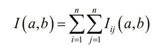
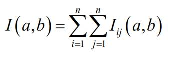
- the composite superposition amplitude I ( a , b ) of the midpoint ( a , b ) in the image is:
- the peak coordinate points in the imaging area are read, and the depth, size and inclination angle of cracks with different orientations can be obtained by the -6 dB method.
- This composite-mode total focusing-based crack topography reconstruction method uses a set of phased array probe wedges to reconstruct the crack topography with different orientations through one signal acquisition, and simultaneously realize the topography characterization of cracks with different orientations, which is the crack length, Accurate quantification of depth and orientation provides an efficient solution.
- the algorithm involved in this method can be embedded in the flaw detector to realize the detection and quantification of cracks with unknown orientation, which has high engineering application and promotion value.
- Figure 1 is a schematic diagram of the ultrasonic detection system used.
- Figure 2 is a schematic diagram of a test block for processing cracks with different orientations.
- Figure 3 is a schematic diagram of a coordinate system established during signal acquisition.
- Figure 4 is a composite mode all-focus reconstructed image of a crack with a center depth of 24 mm, a length of 5 mm, and an orientation angle of -60° in the tested block.
- Figure 5 is a composite mode full-focus reconstructed image of a crack with a center depth of 24 mm, a length of 5 mm, and an orientation angle of -30° in the tested block.
- Figure 6 is a composite-mode all-focus reconstructed image of a crack with a center depth of 24 mm, a length of 5 mm, and an orientation angle of 0° in the tested block.
- Figure 7 is a composite mode full-focus reconstructed image of a crack with a center depth of 24 mm, a length of 5 mm, and an orientation angle of 30° in the tested block.
- Figure 8 is a composite-mode full-focus reconstruction image of a crack with a center depth of 24 mm, a length of 5 mm, and an orientation angle of 60° in the tested block.
- the ultrasonic inspection system used is shown in Figure 1, which includes a phased array ultrasonic detector, a phased array ultrasonic probe, and a tilted plexiglass wedge.
- Figure 1 includes a phased array ultrasonic detector, a phased array ultrasonic probe, and a tilted plexiglass wedge.
- the specific detection and processing steps are as follows:
- the tested block is a carbon steel test block with a thickness of 40 mm.
- the test block is machined with a center depth of 24 mm and a length of 5 mm.
- the orientation angles are 0°, ⁇ 30° and ⁇ 60° respectively (vertical direction). is 0°, clockwise is positive), as shown in Figure 2.
- phased array probe with a center frequency of 5 MHz and 64 array elements was used to detect the test block with a 45° wedge block.
- the height of the first array element of the probe was 18.82 mm. mm, the sampling frequency is 100 MHz, and the sound speed of the longitudinal wave of the wedge is 2330 m/s, the sound speed of transverse wave of the test block is 3230 m/s, and the speed of longitudinal wave is 5900 m/s.
- t pi denotes the i th array element to propagate the excitation beam reconstruction using the time point
- t pj represents the backscattering reconstruction point reaches the j-th array element used time
- t p ( a , b ) is the propagation time of the p- th mode wave at point ( a , b );
- the composite superposition amplitude I ( a , b ) of the midpoint ( a , b ) in the image is:
- the center depth positioning results are 23.60 respectively mm, 23.78 mm, 24.58 mm, 24.21 mm and 24.30 mm
- the quantitative results of the orientation angles are -59.42°, -30.78°, -0.56°, 29.76° and 59.98°, respectively.
- the quantitative error does not exceed 0.38 mm, 0.58 mm and 0.78°, respectively.
- the method realizes the reconstruction of cracks with different orientations, and the quantitative and positioning errors are small, which meets the engineering requirements.
- This composite-mode total focusing-based crack topography reconstruction method uses a set of phased array probe wedges to reconstruct the crack topography with different orientations through one signal acquisition, and simultaneously realize the topography characterization of cracks with different orientations, which is the crack length, Accurate quantification of depth and orientation provides an efficient solution.
- the algorithm involved in this method can be embedded in the flaw detector to realize the detection and quantification of cracks with unknown orientation, which has high engineering application and promotion value.
Landscapes
- Physics & Mathematics (AREA)
- General Physics & Mathematics (AREA)
- Immunology (AREA)
- Analytical Chemistry (AREA)
- Biochemistry (AREA)
- General Health & Medical Sciences (AREA)
- Life Sciences & Earth Sciences (AREA)
- Health & Medical Sciences (AREA)
- Pathology (AREA)
- Chemical & Material Sciences (AREA)
- Acoustics & Sound (AREA)
- Engineering & Computer Science (AREA)
- Signal Processing (AREA)
- Algebra (AREA)
- Mathematical Physics (AREA)
- Pure & Applied Mathematics (AREA)
- Mathematical Optimization (AREA)
- Mathematical Analysis (AREA)
- Investigating Or Analyzing Materials By The Use Of Ultrasonic Waves (AREA)
Abstract
一种基于复合模式全聚焦的裂纹形貌重建方法,其属于无损检测技术领域。采用相控阵超声检测仪、相控阵超声探头和倾斜楔块构成的相控阵超声检测系统,利用相控阵全矩阵捕捉模块采集包括21种模式波的A扫描信号矩阵;基于费马定理,计算21种模式波在楔块与被检试块界面处的折射点位置,得到被检区域内每种模式波的幅值信号;针对每一个重建点从21种模式波中选择能量最强信号;最后,通过复合叠加实现不同取向裂纹的形貌重建。能够利用一套探头楔块组合,通过一次信号采集实现不同取向裂纹形貌重建,进而对裂纹长度、深度和取向精确定量;可嵌入到探伤仪中,实现未知取向裂纹检出与定量,具有较高工程应用前景。
Description
本发明涉及一种基于复合模式全聚焦的裂纹形貌重建方法,其属于无损检测技术领域。
裂纹定量、定位和定取向是无损检测领域始终关注的问题。常规相控阵超声检测技术具有对面积型缺陷敏感、成像检测结果显示直观、缺陷定量与定位准确等优点,被广泛用于裂纹检测。然而,常规相控阵超声技术仅能呈现裂纹端点特征,成像结果受裂纹取向影响,不能给出裂纹完整形貌信息,甚至可能引起缺陷性质误判,导致缺陷危害程度估计不足。
为解决上述问题,国内外学者结合成像处理技术改善图像质量,力求直观、全面和准确地呈现裂纹形貌特征信息。逆时偏移成像可以获得裂纹近似形貌,但方法适用性受噪声影响较大,且计算效率偏低。全聚焦方法利用相控阵超声各阵元依次激励声波,且所有阵元同时接收回波信号,以获得包含被检裂纹信息的全矩阵数据。该方法可以提升成像分辨力和信噪比,但不能完整表征裂纹形貌。
在此基础上,考虑直接、半跨和全跨模式,共存在21种模式波。对于特定取向裂纹,可从上述21种模式波中选取指向性最好的一种进行延时叠加成像,从而给出该裂纹形貌特征。这种方法称为多模式全聚焦方法,其适用范围受楔块角度与裂纹取向的相对关系影响,每种模式波可表征的裂纹取向范围不超过20°。特别是待测缺陷取向未知时,难以明确成像所用模式波类型,检测效率和可靠性降低。
本发明提供一种基于复合模式全聚焦的裂纹形貌重建方法,其目的是针对裂纹形貌完整表征困难、可能引起缺陷性质误判的问题,利用相控阵超声检测仪的全矩阵捕捉功能配合倾斜楔块采集A扫描信号矩阵,并对被检区域逐点进行21种模式波中能量最强信号的复合叠加,实现不同取向裂纹的完整形貌表征。
本发明采用的技术方案是:采用由相控阵超声检测仪、相控阵超声探头和倾斜楔块构成的检测系统,采集包括21种模式波的A扫描信号矩阵;基于费马定理,计算21种模式波在楔块与被检试块界面处的折射点位置,得到被检区域内每种模式波的幅值信号;针对每一个重建点,从上述21种模式波中选择能量最强信号;最后,通过复合叠加实现不同取向裂纹的形貌重建;所述方法采用下列步骤:
(a)相控阵超声检测参数选择
根据被检试块的材料、形状和尺寸信息选取相控阵超声检测参数,参数包括相控阵超声探头频率、阵元数量以及楔块型号;
(b)A扫描信号矩阵采集
基于选定的相控阵超声检测参数,利用相控阵超声检测仪全矩阵捕捉功能一次采集包括不同模式波的A扫描信号矩阵,并以txt格式保存;对于一个阵元数为
n的相控阵探头,A扫描信号数量为
n²;
(c)坐标系建立及图像重建区域网格划分
以楔块和被检试块界面为
x轴,探头第一阵元中心位置到
x轴的投影点为坐标原点,楔块前沿方向为
x轴正向,试块深度方向为
y轴正向建立坐标系,将被检区域划分成
M×
N个矩形网格,网格节点即为各图像重建点;
(d)模式波种类确定
根据声束传播路径不同,分为三类模式:直接模式中声束由阵元发射,与裂纹作用后直接返回阵元;半跨模式中声束由阵元发射经试块底部反射后,与裂纹作用并直接返回阵元;全跨模式中声束由阵元发射,经试块底部反射与裂纹作用后,又经底部反射返回至阵元;超声波在楔块与被检试块界面、试块底部和裂纹表面发生波型转换,故三类模式共分为21种波型组合;
(e)折射点位置求解
第
p种模式波发射和接收时,在楔块和被检试块界面处的折射点横坐标分别为
x
pi
与
x
pj
,根据费马定理利用式(1)求出:

式中,1≤
p≤21,
t
pi
表示第
i个阵元激励声束传播到重建点所用时间,
t
pj
表示重建点散射回波到达第
j个阵元所用时间;根据声束传播路径与波型,求得
t
pi
与
t
pj
;
(f)复合模式全聚焦图像重建
对于每一个图像重建点(
a,
b),其中1≤
a≤
M,1≤
b≤
N,在第
i个阵元发射,第
j个阵元接收的信号
A
ij
中筛选21种模式波中能量最强信号,得到该点对应幅值
I
ij
(
a,
b):
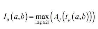
式中,
t
p
(
a,
b)为第
p种模式波在点(
a,
b)处的传播时间;
重复以上步骤对被检区域逐点进行复合叠加,得到复合模式全聚焦重建图像,图像中点(
a,
b)的复合叠加幅值
I(
a,
b)为:
(g)裂纹定量、定位和定取向
依据复合模式全聚焦成像结果,读取成像区域内的峰值坐标点,利用-6 dB法即获得不同取向裂纹的深度、尺寸与倾斜角度。
这种基于复合模式全聚焦的裂纹形貌重建方法利用一套相控阵探头楔块组合,通过一次信号采集实现不同取向裂纹形貌重建,同时实现不同取向裂纹的形貌表征,为裂纹长度、深度和取向的精确定量提供了有效解决方法。同时,该方法涉及的算法可嵌入到探伤仪中,实现未知取向裂纹检出与定量,具有较高的工程应用和推广价值。
下面结合附图和实例对本发明做进一步说明。
图1是采用的超声检测系统示意图。
图2是加工不同取向裂纹的试块示意图。
图3是信号采集时建立的坐标系示意图。
图4是被检试块内部中心深度24 mm、长度5 mm、取向角度-60°裂纹的复合模式全聚焦重建图像。
图5是被检试块内部中心深度24 mm、长度5 mm、取向角度-30°裂纹的复合模式全聚焦重建图像。
图6是被检试块内部中心深度24 mm、长度5 mm、取向角度0°裂纹的复合模式全聚焦重建图像。
图7是被检试块内部中心深度24 mm、长度5 mm、取向角度30°裂纹的复合模式全聚焦重建图像。
图8是被检试块内部中心深度24 mm、长度5 mm、取向角度60°裂纹的复合模式全聚焦重建图像。
基于复合模式全聚焦的裂纹形貌重建方法,采用的超声检测系统如图1所示,其中包括相控阵超声检测仪、相控阵超声探头、倾斜有机玻璃楔块。具体检测及处理步骤如下:
(a)被检试块为厚度40 mm的碳钢试块,试块中加工了中心深度24 mm、长度5 mm,取向角度分别为0°、±30°和±60°裂纹(竖直方向为0°,顺时针方向为正),如图2所示。
利用相控阵超声检测仪,采用中心频率5 MHz、64阵元的相控阵探头配合45°楔块对试块进行检测,其中探头第一阵元高度18.82
mm、采样频率100 MHz,楔块纵波声速为2330
m/s,试块横波声速3230 m/s,纵波声速5900
m/s。
(b)利用相控阵超声检测仪的全矩阵捕捉功能对被检试块进行信号采集,获得包含不同模式波的A扫描信号矩阵,以数据文本形式导出,A扫描信号数量为64²=4096。
(c)如图3所示,建立直角坐标系:以楔块和被检试块界面为
x轴,探头第一阵元中心位置到
x轴的投影点为坐标原点,楔块前沿方向为
x轴正向,试块深度方向为
y轴正向建立坐标系,并将检测区域划分成100×100个矩形网格。
(d)根据声束传播路径不同,分为三类模式:直接模式中声束由阵元发射,与裂纹作用后直接返回阵元;半跨模式中声束由阵元发射经试块底部反射后,与裂纹作用并直接返回阵元;全跨模式中声束由阵元发射,经试块底部反射与裂纹作用后,又经底部反射返回至阵元;超声波在楔块与被检试块界面、试块底部和裂纹表面发生波型转换,故三类模式共分为21种波型组合;
(e)折射点位置求解
第
p种模式波发射和接收时,在楔块和被检试块界面处的折射点横坐标分别为
x
pi
与
x
pj
,根据费马定理利用式(1)求出:
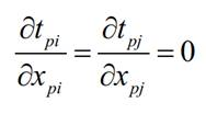
式中,1≤
p≤21,
t
pi
表示第
i个阵元激励声束传播到重建点所用时间,
t
pj
表示重建点散射回波到达第
j个阵元所用时间;根据声束传播路径与波型,求得
t
pi
与
t
pj
;
(f)复合模式全聚焦图像重建
对于每一个图像重建点(
a,
b),其中1≤
a≤
M,1≤
b≤
N,在第
i个阵元发射,第
j个阵元接收的信号
A
ij
中筛选21种模式波中能量最强信号,得到该点对应幅值
I
ij
(
a,
b):
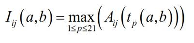
式中,
t
p
(
a,
b)为第
p种模式波在点(
a,
b)处的传播时间;
重复以上步骤对被检区域逐点进行复合叠加,得到复合模式全聚焦重建图像,图像中点(
a,
b)的复合叠加幅值
I(
a,
b)为:
(g)针对21种模式波进行信号复合叠加,得到复合模式全聚焦图像。图4至图8依次给出取向角度-60°、-30°、0°、30°和60°裂纹的复合模式全聚焦图像。由图可见,裂纹成像质量好,检测分辨力较高,且整体形貌得到完整表征。计算可得,-60°、-30°、0°、30°和60°裂纹长度定量结果分别为5.11 mm、5.38
mm、5.15 mm、5.38
mm和5.20 mm,中心深度定位结果分别为23.60
mm、23.78 mm、24.58
mm、24.21 mm和24.30
mm,取向角度定量结果分别为-59.42°、-30.78°、-0.56°、29.76°和59.98°。与预设裂纹的长度、深度和取向角度相比,定量误差分别不超过0.38 mm、0.58 mm和0.78°。该方法实现了不同取向裂纹形貌重建,且定量和定位误差较小,满足工程需求。
同最佳实施方式。
这种基于复合模式全聚焦的裂纹形貌重建方法利用一套相控阵探头楔块组合,通过一次信号采集实现不同取向裂纹形貌重建,同时实现不同取向裂纹的形貌表征,为裂纹长度、深度和取向的精确定量提供了有效解决方法。同时,该方法涉及的算法可嵌入到探伤仪中,实现未知取向裂纹检出与定量,具有较高的工程应用和推广价值。
无。
Claims (1)
- 一种基于复合模式全聚焦的裂纹形貌重建方法,其特征在于:该方法采用由相控阵超声检测仪、相控阵超声探头和倾斜楔块构成的检测系统,采集包括21种模式波的A扫描信号矩阵;基于费马定理,计算21种模式波在楔块与被检试块界面处的折射点位置,得到被检区域内每种模式波的幅值信号;针对每一个重建点,从上述21种模式波中选择能量最强信号;最后,通过复合叠加实现不同取向裂纹的形貌重建;所述方法采用下列步骤:(a)相控阵超声检测参数选择根据被检试块的材料、形状和尺寸信息选取相控阵超声检测参数,参数包括相控阵超声探头频率、阵元数量以及楔块型号;(b)A扫描信号矩阵采集基于选定的相控阵超声检测参数,利用相控阵超声检测仪全矩阵捕捉功能一次采集包括不同模式波的A扫描信号矩阵,并以txt格式保存;对于一个阵元数为 n的相控阵探头,A扫描信号数量为 n²;(c)坐标系建立及图像重建区域网格划分以楔块和被检试块界面为 x轴,探头第一阵元中心位置到 x轴的投影点为坐标原点,楔块前沿方向为 x轴正向,试块深度方向为 y轴正向建立坐标系,将被检区域划分成 M× N个矩形网格,网格节点即为各图像重建点;(d)模式波种类确定根据声束传播路径不同,分为三类模式:直接模式中声束由阵元发射,与裂纹作用后直接返回阵元;半跨模式中声束由阵元发射经试块底部反射后,与裂纹作用并直接返回阵元;全跨模式中声束由阵元发射,经试块底部反射与裂纹作用后,又经底部反射返回至阵元;超声波在楔块与被检试块界面、试块底部和裂纹表面发生波型转换,故三类模式共分为21种波型组合;(e)折射点位置求解第 p种模式波发射和接收时,在楔块和被检试块界面处的折射点横坐标分别为 x pi 与 x pj ,根据费马定理利用式(1)求出:(1)
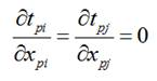 式中,1≤ p≤21, t pi 表示第 i个阵元激励声束传播到重建点所用时间, t pj 表示重建点散射回波到达第 j个阵元所用时间;根据声束传播路径与波型,求得 t pi 与 t pj ;(f)复合模式全聚焦图像重建对于每一个图像重建点( a, b),其中1≤ a≤ M,1≤ b≤ N,在第 i个阵元发射,第 j个阵元接收的信号 A ij 中筛选21种模式波中能量最强信号,得到该点对应幅值 I ij ( a, b):(2)
 式中, t p ( a, b)为第 p种模式波在点( a, b)处的传播时间;重复以上步骤对被检区域逐点进行复合叠加,得到复合模式全聚焦重建图像,图像中点( a, b)的复合叠加幅值 I( a, b)为:(3)
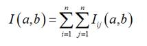 (g)裂纹定量、定位和定取向依据复合模式全聚焦成像结果,读取成像区域内的峰值坐标点,利用-6 dB法即获得不同取向裂纹的深度、尺寸与倾斜角度。
Priority Applications (1)
| Application Number | Priority Date | Filing Date | Title |
|---|---|---|---|
| US17/549,908 US12007362B2 (en) | 2020-07-20 | 2021-12-14 | Method for reconstructing crack profiles based on composite-mode total focusing method |
Applications Claiming Priority (2)
| Application Number | Priority Date | Filing Date | Title |
|---|---|---|---|
| CN202010696063.0A CN111855809B (zh) | 2020-07-20 | 2020-07-20 | 一种基于复合模式全聚焦的裂纹形貌重建方法 |
| CN202010696063.0 | 2020-07-20 |
Related Child Applications (1)
| Application Number | Title | Priority Date | Filing Date |
|---|---|---|---|
| US17/549,908 Continuation-In-Part US12007362B2 (en) | 2020-07-20 | 2021-12-14 | Method for reconstructing crack profiles based on composite-mode total focusing method |
Publications (1)
| Publication Number | Publication Date |
|---|---|
| WO2022016726A1 true WO2022016726A1 (zh) | 2022-01-27 |
Family
ID=73002423
Family Applications (1)
| Application Number | Title | Priority Date | Filing Date |
|---|---|---|---|
| PCT/CN2020/124195 Ceased WO2022016726A1 (zh) | 2020-07-20 | 2020-10-28 | 一种基于复合模式全聚焦的裂纹形貌重建方法 |
Country Status (3)
| Country | Link |
|---|---|
| US (1) | US12007362B2 (zh) |
| CN (1) | CN111855809B (zh) |
| WO (1) | WO2022016726A1 (zh) |
Cited By (4)
| Publication number | Priority date | Publication date | Assignee | Title |
|---|---|---|---|---|
| CN114624241A (zh) * | 2022-03-12 | 2022-06-14 | 北京工业大学 | 一种基于改进的全聚焦算法的风机主轴裂纹成像方法 |
| CN116147918A (zh) * | 2023-03-08 | 2023-05-23 | 西安热工研究院有限公司 | 一种在役风力发电机变桨轴承滚道检测系统及其使用方法 |
| CN116660371A (zh) * | 2023-05-26 | 2023-08-29 | 大连理工大学 | 基于多帧多模式波融合的管道轴向缺陷全聚焦成像方法 |
| US12140569B2 (en) | 2021-05-27 | 2024-11-12 | Airbus Operations Sas | Method and system for an ultrasonic detection of internal defects of a component, in particular for an aircraft |
Families Citing this family (15)
| Publication number | Priority date | Publication date | Assignee | Title |
|---|---|---|---|---|
| US11686707B2 (en) | 2020-03-30 | 2023-06-27 | Verifi Technologies, Llc | System and method for real-time visualization of defects in a material |
| US11726065B2 (en) | 2020-03-30 | 2023-08-15 | Verifi Technologies, Llc | System and method for real-time visualization of defects in a material |
| CN113552218B (zh) * | 2021-07-16 | 2022-09-06 | 大连理工大学 | 基于阵列超声信号幅值和相位特征加权的缺陷定性检测方法 |
| CN113552217B (zh) * | 2021-07-16 | 2022-05-10 | 大连理工大学 | 一种基于双自发自收相控阵探头的未知缺陷轮廓重建方法 |
| CN114019027B (zh) * | 2021-10-22 | 2025-01-10 | 中国计量大学 | 聚乙烯管的热熔接头的检测方法、系统、上位机 |
| CN115047079B (zh) * | 2022-08-17 | 2022-10-21 | 南通友联数码技术开发有限公司 | 一种用于多层复合板的超声相控阵快速聚焦方法 |
| CN115575496B (zh) * | 2022-09-30 | 2024-06-14 | 大连理工大学 | 一种基于反距离权重的高分辨力超声频域全聚焦方法 |
| CN115993398A (zh) * | 2022-09-30 | 2023-04-21 | 大连理工大学 | 一种基于高阶模式全聚焦的薄板焊缝缺陷轮廓重建方法 |
| CN116046894B (zh) * | 2022-09-30 | 2025-09-26 | 大连理工大学 | 基于修正模式合成孔径聚焦的管道轴向缺陷超声成像方法 |
| CN115856076B (zh) * | 2022-11-23 | 2023-06-16 | 国营芜湖机械厂 | 基于空耦超声的cfrp板小尺寸缺陷测量方法、装置及系统 |
| CN115937294B (zh) * | 2022-12-30 | 2023-10-27 | 重庆大学 | 一种煤矿地面压裂后采空区垮裂带高度的预测方法 |
| CN116183720A (zh) * | 2023-01-08 | 2023-05-30 | 北京工业大学 | 一种基于超声波空间响应补偿的多模式复合全聚焦成像方法 |
| CN115856087B (zh) * | 2023-02-27 | 2023-05-19 | 南昌航空大学 | 基于纵波一发一收超声相控阵探头的全聚焦成像方法 |
| CN116152646B (zh) * | 2023-03-09 | 2026-01-30 | 哈电发电设备国家工程研究中心有限公司 | 一种基于图像处理的汽轮机低压缸末级叶片裂纹识别方法 |
| CN117849184B (zh) * | 2024-03-07 | 2024-05-07 | 广东汕头超声电子股份有限公司 | 一种对置阵列多模态全聚焦焊缝检测方法 |
Citations (3)
| Publication number | Priority date | Publication date | Assignee | Title |
|---|---|---|---|---|
| US20030079545A1 (en) * | 2001-10-30 | 2003-05-01 | Matney Russell M. | UT detection and sizing method for thin wall tubes |
| CN106093206A (zh) * | 2016-07-15 | 2016-11-09 | 国网浙江省电力公司电力科学研究院 | 一种基于斜入射纵波的焊缝超声阵列全聚焦成像方法 |
| CN106770669A (zh) * | 2017-01-20 | 2017-05-31 | 大连理工大学 | 基于多模式声束合成孔径聚焦的缺陷二维形貌成像检测方法 |
Family Cites Families (10)
| Publication number | Priority date | Publication date | Assignee | Title |
|---|---|---|---|---|
| JPS5963563A (ja) * | 1982-10-05 | 1984-04-11 | Tokyo Keiki Co Ltd | 中実部材の超音波自動探傷装置 |
| US6393917B1 (en) * | 1999-08-16 | 2002-05-28 | Suh Dong-Man | System and method for ultrasonic image reconstruction using mode-converted Rayleigh wave |
| US20070000328A1 (en) * | 2005-01-06 | 2007-01-04 | Jonathan Buttram | Ultrasonic method for the accurate measurement of crack height in dissimilar metal welds using phased array |
| KR20070065934A (ko) * | 2005-10-31 | 2007-06-27 | 한국전력공사 | 위상배열 초음파 결함길이평가 장치 및 그 방법 |
| US9551690B2 (en) * | 2011-03-31 | 2017-01-24 | Atomic Energy Of Canada Limited | Profiling tool for determining material thickness for inspection sites having complex topography |
| US8770029B2 (en) * | 2011-10-04 | 2014-07-08 | General Electric Company | Method and apparatus for ultrasonic testing |
| CN106093205B (zh) * | 2016-05-31 | 2019-04-09 | 大连理工大学 | 一种基于斜入射超声合成孔径聚焦的厚壁结构缺陷检测方法 |
| CN106383171A (zh) * | 2016-08-26 | 2017-02-08 | 广东汕头超声电子股份有限公司 | 一种钢板焊缝裂纹缺陷的横波全聚焦超声成像检测方法 |
| KR102037692B1 (ko) * | 2018-05-28 | 2019-11-26 | 한국표준과학연구원 | 위상배열 초음파 탐촉자 및 웨지를 이용한 초음파 검사 방법 |
| US11474075B2 (en) * | 2019-10-30 | 2022-10-18 | Olympus NDT Canada Inc. | Total focusing method (TFM) with acoustic path filtering |
-
2020
- 2020-07-20 CN CN202010696063.0A patent/CN111855809B/zh active Active
- 2020-10-28 WO PCT/CN2020/124195 patent/WO2022016726A1/zh not_active Ceased
-
2021
- 2021-12-14 US US17/549,908 patent/US12007362B2/en active Active
Patent Citations (3)
| Publication number | Priority date | Publication date | Assignee | Title |
|---|---|---|---|---|
| US20030079545A1 (en) * | 2001-10-30 | 2003-05-01 | Matney Russell M. | UT detection and sizing method for thin wall tubes |
| CN106093206A (zh) * | 2016-07-15 | 2016-11-09 | 国网浙江省电力公司电力科学研究院 | 一种基于斜入射纵波的焊缝超声阵列全聚焦成像方法 |
| CN106770669A (zh) * | 2017-01-20 | 2017-05-31 | 大连理工大学 | 基于多模式声束合成孔径聚焦的缺陷二维形貌成像检测方法 |
Non-Patent Citations (3)
| Title |
|---|
| HAN XIAO-LI; WU WEN-TAO; LI PING; LIN JING: "Combination of direct, half-skip and full-skip TFM to characterize multi-faceted crack", 2015 IEEE INTERNATIONAL ULTRASONICS SYMPOSIUM (IUS), IEEE, 21 October 2015 (2015-10-21), pages 1 - 4, XP032799426, DOI: 10.1109/ULTSYM.2015.0339 * |
| HAN XIAOLI; WU WENTAO; ZHANG DI; WAN HAITAO: "Combination of direct, half-skip and full-skip TFM to characterize defect(II)", 2019 IEEE INTERNATIONAL ULTRASONICS SYMPOSIUM (IUS), IEEE, 6 October 2019 (2019-10-06), pages 1612 - 1615, XP033671334, DOI: 10.1109/ULTSYM.2019.8925989 * |
| JIN SHI-JIE; LIU CHEN-FEI; SHI SI-QI; LUO ZHONG-BING; WANG CHU; LIN LI: "Comparison of Morphology Characterization for Regular Cracks with Multi-mode Total Focusing Method", 2019 FAR EAST NDT NEW TECHNOLOGY & APPLICATION FORUM (FENDT), IEEE, 24 June 2019 (2019-06-24), pages 21 - 25, XP033692584, DOI: 10.1109/FENDT47723.2019.8962560 * |
Cited By (4)
| Publication number | Priority date | Publication date | Assignee | Title |
|---|---|---|---|---|
| US12140569B2 (en) | 2021-05-27 | 2024-11-12 | Airbus Operations Sas | Method and system for an ultrasonic detection of internal defects of a component, in particular for an aircraft |
| CN114624241A (zh) * | 2022-03-12 | 2022-06-14 | 北京工业大学 | 一种基于改进的全聚焦算法的风机主轴裂纹成像方法 |
| CN116147918A (zh) * | 2023-03-08 | 2023-05-23 | 西安热工研究院有限公司 | 一种在役风力发电机变桨轴承滚道检测系统及其使用方法 |
| CN116660371A (zh) * | 2023-05-26 | 2023-08-29 | 大连理工大学 | 基于多帧多模式波融合的管道轴向缺陷全聚焦成像方法 |
Also Published As
| Publication number | Publication date |
|---|---|
| CN111855809A (zh) | 2020-10-30 |
| CN111855809B (zh) | 2022-07-26 |
| US20220107290A1 (en) | 2022-04-07 |
| US12007362B2 (en) | 2024-06-11 |
Similar Documents
| Publication | Publication Date | Title |
|---|---|---|
| WO2022016726A1 (zh) | 一种基于复合模式全聚焦的裂纹形貌重建方法 | |
| CN106770669B (zh) | 基于多模式声束合成孔径聚焦的缺陷二维形貌成像检测方法 | |
| CN105699492B (zh) | 一种用于焊缝检测的超声成像方法 | |
| US20230061816A1 (en) | Air-coupled Ultrasonic Detection Method and Device Based on Defect Probability Reconstruction Algorithm | |
| WO2020191972A1 (zh) | 一种超声检测缺陷定性系统和定性方法 | |
| CN106093205A (zh) | 一种基于斜入射超声合成孔径聚焦的厚壁结构缺陷检测方法 | |
| CN102221579B (zh) | 基于多晶探头的超声检测缺陷信息采集方法 | |
| CN113552217B (zh) | 一种基于双自发自收相控阵探头的未知缺陷轮廓重建方法 | |
| CN108445076A (zh) | 一种基于t形角焊缝横向裂纹超声波检测方法 | |
| CN117191948A (zh) | 一种基于虚拟源的超声漏表面波全聚焦成像方法 | |
| CN107356670A (zh) | 一种基于斜入射的超声相控阵焊缝缺陷检测方法 | |
| CN111257426A (zh) | 火箭燃料贮箱焊缝的多模式全聚焦检测方法、系统及介质 | |
| CN110988139A (zh) | 一种浮标底板与舢板焊接相控阵超声检测方法 | |
| CN202837253U (zh) | 一种火车车轮超声波探伤用试块组件 | |
| CN115389625B (zh) | 一种用于检测复合材料面外纤维弯曲的双面超声成像方法 | |
| CN115993398A (zh) | 一种基于高阶模式全聚焦的薄板焊缝缺陷轮廓重建方法 | |
| CN112798685B (zh) | 一种基于超声相控阵的u肋焊缝检测方法 | |
| CN119959363A (zh) | 基于阵元指向的钢筋混凝土超声阵列成像的图像校正方法 | |
| CN117092218A (zh) | 一种基于均方根速度的超声相控阵漏表面波全聚焦成像方法 | |
| CN115856087B (zh) | 基于纵波一发一收超声相控阵探头的全聚焦成像方法 | |
| CN113552218B (zh) | 基于阵列超声信号幅值和相位特征加权的缺陷定性检测方法 | |
| CN120927823A (zh) | 一种基于多模态超声的固态电池固化状态的无损检测方法 | |
| CN105353039A (zh) | 对接焊接接头的相控阵纵波检测方式 | |
| CN114428118B (zh) | 一种双阵列超声成像检测方法及检测装置 | |
| CN117491504A (zh) | 一种基于一发一收相控阵探头的分层缺陷轮廓重建方法 |
Legal Events
| Date | Code | Title | Description |
|---|---|---|---|
| 121 | Ep: the epo has been informed by wipo that ep was designated in this application |
Ref document number: 20946498 Country of ref document: EP Kind code of ref document: A1 |
|
| NENP | Non-entry into the national phase |
Ref country code: DE |
|
| 122 | Ep: pct application non-entry in european phase |
Ref document number: 20946498 Country of ref document: EP Kind code of ref document: A1 |