WO2022014772A1 - 머신 러닝 기반 디지털 홀로그래피 장치 및 이의 동작 방법 - Google Patents
머신 러닝 기반 디지털 홀로그래피 장치 및 이의 동작 방법 Download PDFInfo
- Publication number
- WO2022014772A1 WO2022014772A1 PCT/KR2020/011619 KR2020011619W WO2022014772A1 WO 2022014772 A1 WO2022014772 A1 WO 2022014772A1 KR 2020011619 W KR2020011619 W KR 2020011619W WO 2022014772 A1 WO2022014772 A1 WO 2022014772A1
- Authority
- WO
- WIPO (PCT)
- Prior art keywords
- sample
- image
- holographic
- holographic image
- digital holography
- Prior art date
- Legal status (The legal status is an assumption and is not a legal conclusion. Google has not performed a legal analysis and makes no representation as to the accuracy of the status listed.)
- Ceased
Links
Images




Classifications
-
- G—PHYSICS
- G03—PHOTOGRAPHY; CINEMATOGRAPHY; ANALOGOUS TECHNIQUES USING WAVES OTHER THAN OPTICAL WAVES; ELECTROGRAPHY; HOLOGRAPHY
- G03H—HOLOGRAPHIC PROCESSES OR APPARATUS
- G03H1/00—Holographic processes or apparatus using light, infrared or ultraviolet waves for obtaining holograms or for obtaining an image from them; Details peculiar thereto
- G03H1/0005—Adaptation of holography to specific applications
-
- G—PHYSICS
- G03—PHOTOGRAPHY; CINEMATOGRAPHY; ANALOGOUS TECHNIQUES USING WAVES OTHER THAN OPTICAL WAVES; ELECTROGRAPHY; HOLOGRAPHY
- G03H—HOLOGRAPHIC PROCESSES OR APPARATUS
- G03H1/00—Holographic processes or apparatus using light, infrared or ultraviolet waves for obtaining holograms or for obtaining an image from them; Details peculiar thereto
- G03H1/04—Processes or apparatus for producing holograms
- G03H1/0443—Digital holography, i.e. recording holograms with digital recording means
-
- G—PHYSICS
- G02—OPTICS
- G02B—OPTICAL ELEMENTS, SYSTEMS OR APPARATUS
- G02B21/00—Microscopes
- G02B21/06—Means for illuminating specimens
- G02B21/08—Condensers
- G02B21/12—Condensers affording bright-field illumination
-
- G—PHYSICS
- G03—PHOTOGRAPHY; CINEMATOGRAPHY; ANALOGOUS TECHNIQUES USING WAVES OTHER THAN OPTICAL WAVES; ELECTROGRAPHY; HOLOGRAPHY
- G03H—HOLOGRAPHIC PROCESSES OR APPARATUS
- G03H1/00—Holographic processes or apparatus using light, infrared or ultraviolet waves for obtaining holograms or for obtaining an image from them; Details peculiar thereto
- G03H1/04—Processes or apparatus for producing holograms
- G03H1/08—Synthesising holograms, i.e. holograms synthesized from objects or objects from holograms
- G03H1/0808—Methods of numerical synthesis, e.g. coherent ray tracing [CRT], diffraction specific
-
- G—PHYSICS
- G03—PHOTOGRAPHY; CINEMATOGRAPHY; ANALOGOUS TECHNIQUES USING WAVES OTHER THAN OPTICAL WAVES; ELECTROGRAPHY; HOLOGRAPHY
- G03H—HOLOGRAPHIC PROCESSES OR APPARATUS
- G03H1/00—Holographic processes or apparatus using light, infrared or ultraviolet waves for obtaining holograms or for obtaining an image from them; Details peculiar thereto
- G03H1/04—Processes or apparatus for producing holograms
- G03H1/08—Synthesising holograms, i.e. holograms synthesized from objects or objects from holograms
- G03H1/0866—Digital holographic imaging, i.e. synthesizing holobjects from holograms
-
- G—PHYSICS
- G03—PHOTOGRAPHY; CINEMATOGRAPHY; ANALOGOUS TECHNIQUES USING WAVES OTHER THAN OPTICAL WAVES; ELECTROGRAPHY; HOLOGRAPHY
- G03H—HOLOGRAPHIC PROCESSES OR APPARATUS
- G03H1/00—Holographic processes or apparatus using light, infrared or ultraviolet waves for obtaining holograms or for obtaining an image from them; Details peculiar thereto
- G03H1/22—Processes or apparatus for obtaining an optical image from holograms
- G03H1/24—Processes or apparatus for obtaining an optical image from holograms using white light, e.g. rainbow holograms
-
- G—PHYSICS
- G06—COMPUTING OR CALCULATING; COUNTING
- G06N—COMPUTING ARRANGEMENTS BASED ON SPECIFIC COMPUTATIONAL MODELS
- G06N3/00—Computing arrangements based on biological models
- G06N3/02—Neural networks
- G06N3/04—Architecture, e.g. interconnection topology
- G06N3/045—Combinations of networks
-
- G—PHYSICS
- G06—COMPUTING OR CALCULATING; COUNTING
- G06N—COMPUTING ARRANGEMENTS BASED ON SPECIFIC COMPUTATIONAL MODELS
- G06N3/00—Computing arrangements based on biological models
- G06N3/02—Neural networks
- G06N3/04—Architecture, e.g. interconnection topology
- G06N3/0464—Convolutional networks [CNN, ConvNet]
-
- G—PHYSICS
- G06—COMPUTING OR CALCULATING; COUNTING
- G06N—COMPUTING ARRANGEMENTS BASED ON SPECIFIC COMPUTATIONAL MODELS
- G06N3/00—Computing arrangements based on biological models
- G06N3/02—Neural networks
- G06N3/04—Architecture, e.g. interconnection topology
- G06N3/0475—Generative networks
-
- G—PHYSICS
- G06—COMPUTING OR CALCULATING; COUNTING
- G06N—COMPUTING ARRANGEMENTS BASED ON SPECIFIC COMPUTATIONAL MODELS
- G06N3/00—Computing arrangements based on biological models
- G06N3/02—Neural networks
- G06N3/08—Learning methods
-
- G—PHYSICS
- G06—COMPUTING OR CALCULATING; COUNTING
- G06N—COMPUTING ARRANGEMENTS BASED ON SPECIFIC COMPUTATIONAL MODELS
- G06N3/00—Computing arrangements based on biological models
- G06N3/02—Neural networks
- G06N3/08—Learning methods
- G06N3/09—Supervised learning
-
- G—PHYSICS
- G06—COMPUTING OR CALCULATING; COUNTING
- G06N—COMPUTING ARRANGEMENTS BASED ON SPECIFIC COMPUTATIONAL MODELS
- G06N3/00—Computing arrangements based on biological models
- G06N3/02—Neural networks
- G06N3/08—Learning methods
- G06N3/094—Adversarial learning
-
- G—PHYSICS
- G06—COMPUTING OR CALCULATING; COUNTING
- G06T—IMAGE DATA PROCESSING OR GENERATION, IN GENERAL
- G06T7/00—Image analysis
- G06T7/50—Depth or shape recovery
-
- G—PHYSICS
- G06—COMPUTING OR CALCULATING; COUNTING
- G06T—IMAGE DATA PROCESSING OR GENERATION, IN GENERAL
- G06T7/00—Image analysis
- G06T7/50—Depth or shape recovery
- G06T7/55—Depth or shape recovery from multiple images
- G06T7/571—Depth or shape recovery from multiple images from focus
-
- G—PHYSICS
- G02—OPTICS
- G02B—OPTICAL ELEMENTS, SYSTEMS OR APPARATUS
- G02B21/00—Microscopes
- G02B21/0004—Microscopes specially adapted for specific applications
- G02B21/0008—Microscopes having a simple construction, e.g. portable microscopes
-
- G—PHYSICS
- G03—PHOTOGRAPHY; CINEMATOGRAPHY; ANALOGOUS TECHNIQUES USING WAVES OTHER THAN OPTICAL WAVES; ELECTROGRAPHY; HOLOGRAPHY
- G03H—HOLOGRAPHIC PROCESSES OR APPARATUS
- G03H1/00—Holographic processes or apparatus using light, infrared or ultraviolet waves for obtaining holograms or for obtaining an image from them; Details peculiar thereto
- G03H1/0005—Adaptation of holography to specific applications
- G03H2001/005—Adaptation of holography to specific applications in microscopy, e.g. digital holographic microscope [DHM]
-
- G—PHYSICS
- G03—PHOTOGRAPHY; CINEMATOGRAPHY; ANALOGOUS TECHNIQUES USING WAVES OTHER THAN OPTICAL WAVES; ELECTROGRAPHY; HOLOGRAPHY
- G03H—HOLOGRAPHIC PROCESSES OR APPARATUS
- G03H2210/00—Object characteristics
- G03H2210/30—3D object
- G03H2210/33—3D/2D, i.e. the object is formed of stratified 2D planes, e.g. tomographic data
-
- G—PHYSICS
- G03—PHOTOGRAPHY; CINEMATOGRAPHY; ANALOGOUS TECHNIQUES USING WAVES OTHER THAN OPTICAL WAVES; ELECTROGRAPHY; HOLOGRAPHY
- G03H—HOLOGRAPHIC PROCESSES OR APPARATUS
- G03H2222/00—Light sources or light beam properties
- G03H2222/10—Spectral composition
- G03H2222/12—Single or narrow bandwidth source, e.g. laser, light emitting diode [LED]
-
- G—PHYSICS
- G03—PHOTOGRAPHY; CINEMATOGRAPHY; ANALOGOUS TECHNIQUES USING WAVES OTHER THAN OPTICAL WAVES; ELECTROGRAPHY; HOLOGRAPHY
- G03H—HOLOGRAPHIC PROCESSES OR APPARATUS
- G03H2222/00—Light sources or light beam properties
- G03H2222/10—Spectral composition
- G03H2222/17—White light
-
- G—PHYSICS
- G03—PHOTOGRAPHY; CINEMATOGRAPHY; ANALOGOUS TECHNIQUES USING WAVES OTHER THAN OPTICAL WAVES; ELECTROGRAPHY; HOLOGRAPHY
- G03H—HOLOGRAPHIC PROCESSES OR APPARATUS
- G03H2226/00—Electro-optic or electronic components relating to digital holography
- G03H2226/02—Computing or processing means, e.g. digital signal processor [DSP]
-
- G—PHYSICS
- G06—COMPUTING OR CALCULATING; COUNTING
- G06T—IMAGE DATA PROCESSING OR GENERATION, IN GENERAL
- G06T2207/00—Indexing scheme for image analysis or image enhancement
- G06T2207/10—Image acquisition modality
- G06T2207/10056—Microscopic image
-
- G—PHYSICS
- G06—COMPUTING OR CALCULATING; COUNTING
- G06T—IMAGE DATA PROCESSING OR GENERATION, IN GENERAL
- G06T2207/00—Indexing scheme for image analysis or image enhancement
- G06T2207/20—Special algorithmic details
- G06T2207/20081—Training; Learning
-
- G—PHYSICS
- G06—COMPUTING OR CALCULATING; COUNTING
- G06T—IMAGE DATA PROCESSING OR GENERATION, IN GENERAL
- G06T2207/00—Indexing scheme for image analysis or image enhancement
- G06T2207/20—Special algorithmic details
- G06T2207/20084—Artificial neural networks [ANN]
Definitions
- Embodiments relate to a machine learning-based digital holography apparatus and an operating method thereof.
- Bright-field microscopy using white light is an imaging technique widely used in various fields including industry, biology, and medicine.
- Bright-field images are generally used to observe micro-objects such as contaminants, microorganisms, and biological samples.
- optical images since optical images only provide information on the two-dimensional light intensity of the sample within a thin depth of focus of several ⁇ m, the detection and diagnosis accuracy is usually not as high as 90% or less, and the sample exists in the form of a three-dimensional space. is difficult to detect.
- a hologram When coherent light is irradiated to a sample, a hologram is generated by the interference of a material wave diffracted by the sample and a reference wave, and the generated hologram contains 3D image information of the sample in the form of a 2D interference fringe.
- a digital holography microscope (DHM) technique is an imaging technology capable of acquiring optical information along with 3D position and shape information of samples existing in a 3D space from a single holographic image. Since this DHM technique can non-invasively acquire 3D information of a sample from a hologram without a separate labeling and mechanical scanning process, it has been applied in various fields such as monitoring of biological samples, contaminants, and 3D dynamic behavior analysis of particles and cells. .
- the following embodiments may provide a technique for obtaining 3D information of a sample by converting a white light-based optical image into a holographic image using machine learning.
- a digital holography method includes obtaining an optical image including two-dimensional information on a sample, and generating a holographic image including three-dimensional information on the sample based on the optical image.
- the optical image may be an image captured by illuminating the sample with white light.
- the generating may include generating the holographic image by inputting the optical image to a neural network.
- the neural network may be a neural network learned based on an optical image and a holographic image obtained by simultaneously illuminating the same sample with white light and monochromatic light.
- the digital holography method may include acquiring two-dimensional location information of the sample by projecting an image obtained by numerically reconstructing the holographic image in a depth direction onto one plane.
- the digital holography method includes: segmenting an image obtained by numerically reconstructing the holographic image in a depth direction based on a center of the specimen; and a focal plane image of the specimen based on the sharpness of the segmented image. and obtaining depth information of the sample.
- the digital holography method includes acquiring a scattering pattern of light by accumulating a light intensity distribution of the holographic image in a depth direction, and at least one of a real focal length and an imaginary focal length of the sample based on the light scattering pattern It may include the step of extracting.
- a digital holography apparatus includes a memory including instructions and a processor for executing the instructions, and when the instructions are executed by the processor, the processor includes two-dimensional information about the sample.
- a holographic image including three-dimensional information on the sample is generated based on the optical image.
- the optical image may be an optical image photographed by illuminating the sample with white light.
- the processor may learn based on an optical image and a holographic image obtained by simultaneously illuminating the same sample with white light and monochromatic light.
- the processor may acquire two-dimensional position information of the sample by projecting an image obtained by numerically reconstructing the holographic image in a depth direction onto one plane.
- the processor may divide an image obtained by numerically reconstructing the holographic image in a depth direction based on a center of the sample, and obtain depth information of the sample based on sharpness of the divided image. .
- the processor may acquire a light scattering pattern by accumulating a light intensity distribution of the holographic image in a depth direction, and extract at least one of a real focal length and an imaginary focal length of the sample based on the light scattering pattern.
- a learning method of a digital holographic apparatus includes: acquiring an optical image and a first holographic image acquired by simultaneously irradiating white light and monochromatic light on the same sample; 2 generating a holographic image; evaluating the authenticity of the first holographic image and the second holographic image through a second neural network; optimizing the loss function based on the
- the loss function includes a first loss function for the first neural network and a second loss function for the second neural network
- the optimizing includes: the first loss function and the second loss function, respectively
- the method may include adjusting the weights of the first neural network and the second neural network to have a minimum value.
- a digital holography apparatus includes a memory including instructions and a processor for executing the instructions, and when the instructions are executed by the processor, the processor is configured to simultaneously emit white light and monochromatic light to the same sample.
- the authenticity of the image is evaluated, and a loss function is optimized based on the first holographic image, the second holographic image, and the authenticity evaluation result.
- the loss function includes a first loss function for the first neural network and a second loss function for the second neural network, wherein the processor is configured such that the first loss function and the second loss function each have a minimum value.
- the weights of the first neural network and the second neural network may be adjusted to have .
- FIG. 1 is a block diagram schematically illustrating a digital holography apparatus according to an exemplary embodiment.
- FIG. 2 is a diagram illustrating a hybrid imaging apparatus that generates learning data for learning the digital holography apparatus shown in FIG. 1 .
- 3A and 3B are diagrams illustrating learning data generated by the hybrid imaging apparatus shown in FIG. 2 .
- FIG. 4 is a diagram illustrating a network structure included in the digital holography apparatus shown in FIG. 1 .
- FIG. 5 is a diagram illustrating a holographic image generated by the digital holography apparatus shown in FIG. 1 .
- FIG. 6 is a view illustrating a focal plane image obtained by numerically reproducing a holographic image generated by the digital holographic apparatus shown in FIG. 1 .
- FIG. 7A to 7C are diagrams for comparing 2D information of a sample obtained based on an actual holographic image and a holographic image generated by the digital holographic apparatus shown in FIG. 1 .
- FIG. 8A to 8C are diagrams for comparing 3D information of a sample obtained based on an actual holographic image and a holographic image generated by the digital holographic apparatus shown in FIG. 1 .
- FIG. 9A and 9B are diagrams illustrating a light scattering pattern of a sample obtained based on a holographic image generated by the digital holographic apparatus shown in FIG. 1 and an actual holographic image, respectively.
- FIG. 1 is a block diagram schematically illustrating a digital holography apparatus according to an exemplary embodiment.
- the digital holography apparatus 100 may use machine learning to overcome the technical limitations of a conventional optical microscope that provides insufficient information about a sample and a digital holography microscopy (DHM) that requires sophisticated collimated light. .
- DLM digital holography microscopy
- the digital holography apparatus 100 may obtain 3D information of the sample using white light, and detect the sample based on the 3D information. For example, the digital holography apparatus 100 may acquire 3D information of the sample based on a bright-light (BF) image captured by illuminating the sample with white light.
- the white light may include halogen lamps, LED lamps, smartphone flashes, and the like.
- the digital holographic apparatus 100 may generate a holographic image of the sample based on the optical image of the sample photographed using white light. For example, the digital holography apparatus 100 may convert an optical image including 2D information on the sample into a holographic image including 3D information on the sample.
- the digital holography apparatus 100 may extract 3D information of the sample from the generated holographic image. For example, the digital holography apparatus 100 may acquire 3D information of a sample by numerically reconstructing a holographic image at various depths by applying a light diffusion formula.
- the digital holographic apparatus 100 converts a defocused optical image of a sample located at a specific depth into an equivalent holographic image using a neural network, and emits white light without using expensive optical components. It is possible to obtain 3D information of the sample by using it, and use it for sample detection.
- the neural network may include a deep neural network.
- Neural networks include Convolutional Neural Network (CNN), Recurrent Neural Network (RNN), Perceptron, Feed Forward (FF), Radial Basis Network (RBF), Deep Feed Forward (DFF), Long Short Term Memory (LSTM), Gated Recurrent Unit (GRU), Auto Encoder (AE), Variational Auto Encoder (VAE), Denoising Auto Encoder (DAE), Sparse Auto Encoder (SAE), Markov Chain (MC), Hopfield Network (HN), Boltzmann Machine (BM) ), Restricted Boltzmann Machine (RBM), Deep Belief Network (DBN), Deep Convolutional Network (DCN), Deconvolutional Network (DN), Deep Convolutional Inverse Graphics Network (DCIGN), Generative Adversarial Network (GAN), Liquid State Machine (LSM) ), Extreme Learning Machine (ELM), Echo State Network (ESN), Deep Residual Network (DRN), Differential Neural Computer (DNC),
- the digital holography apparatus 100 may include a memory 110 and a processor 150 .
- the memory 110 may store instructions (or programs) executable by the processor 150 .
- the instructions may include instructions for executing an operation of the processor 150 and/or an operation of each component of the processor 150 .
- the memory 110 may be implemented as a volatile memory device or a nonvolatile memory device.
- the volatile memory device may be implemented as dynamic random access memory (DRAM), static random access memory (SRAM), thyristor RAM (T-RAM), zero capacitor RAM (Z-RAM), or twin transistor RAM (TTRAM).
- DRAM dynamic random access memory
- SRAM static random access memory
- T-RAM thyristor RAM
- Z-RAM zero capacitor RAM
- TTRAM twin transistor RAM
- Nonvolatile memory devices include EEPROM (Electrically Erasable Programmable Read-Only Memory), Flash memory, MRAM (Magnetic RAM), Spin-Transfer Torque (STT)-MRAM (Spin-Transfer Torque (STT)-MRAM), Conductive Bridging RAM (CBRAM) , FeRAM(Ferroelectric RAM), PRAM(Phase change RAM), Resistive RAM(RRAM), Nanotube RRAM(Nanotube RRAM), Polymer RAM(Polymer RAM(PoRAM)), Nano Floating Gate Memory (NFGM)), a holographic memory, a molecular electronic memory device, or an Insulator Resistance Change Memory.
- EEPROM Electrically Erasable Programmable Read-Only Memory
- Flash memory Flash memory
- MRAM Magnetic RAM
- STT Spin-Transfer Torque
- STT Spin-Transfer Torque
- CBRAM Conductive Bridging RAM
- FeRAM(Ferroelectric RAM) PRAM(Phase change RAM
- the processor 150 may process data stored in the memory 110 .
- the processor 150 may execute computer readable codes (eg, software) stored in the memory 110 and instructions induced by the processor 150 .
- the processor 150 may be a hardware-implemented data processing device having a circuit having a physical structure for executing desired operations.
- desired operations may include code or instructions included in a program.
- a data processing device implemented as hardware includes a microprocessor, a central processing unit, a processor core, a multi-core processor, and a multiprocessor. , an Application-Specific Integrated Circuit (ASIC), and a Field Programmable Gate Array (FPGA).
- ASIC Application-Specific Integrated Circuit
- FPGA Field Programmable Gate Array
- FIG. 2 is a diagram illustrating a hybrid imaging apparatus generating learning data for learning the digital holography apparatus shown in FIG. 1
- FIGS. 3A and 3B are diagrams illustrating learning data generated by the hybrid imaging apparatus illustrated in FIG. 2 . to be.
- the hybrid imaging apparatus 200 may generate learning data used for learning of the digital holography apparatus 100 .
- the hybrid imaging apparatus 200 may acquire an optical image of the sample and a hologram image corresponding to the optical image.
- the hybrid imaging apparatus 200 may include a first camera 210 , a second camera 220 , a dichroic mirror 230 , an objective lens 240 , and a microchannel 250 .
- the hybrid imaging apparatus 200 may simultaneously illuminate white light and monochromatic light to a sample passing through the microchannel 250 .
- the monochromatic light may be laser parallel light that has passed through a spatial filter.
- the microchannel 250 may include a plurality of microchannels having injection and separation portions. A sample may flow through the microchannel 250 , and white light and monochromatic light may illuminate the sample flowing through the microchannel 250 .
- the objective lens 240 may magnify the optical image and the holographic image obtained by illuminating the microchannel 250 with white light and monochromatic light.
- the objective lens 240 may include a tube lens.
- the dichroic mirror 230 may reflect light of a specific wavelength band and transmit the rest of the light. That is, the dichroic mirror 230 may transmit or reflect light according to the wavelength of the light. The dichroic mirror 230 may reflect monochromatic light toward the second camera 220 and transmit white light toward the first camera 210 .
- the first camera 210 may acquire an optical image by white light.
- the first camera 210 may acquire an optical image of the sample as illustrated in FIG. 3A .
- the second camera 220 may acquire a holographic image using monochromatic light.
- the second camera 220 may acquire a holographic image of the sample as shown in FIG. 3B .
- the first camera 210 and the second camera 220 may be a charge coupled device (CCD) camera or a complementary metal oxide semiconductor (CMOS) camera.
- CCD charge coupled device
- CMOS complementary metal oxide semiconductor
- the optical image and the holographic image of the sample obtained by the hybrid imaging apparatus 200 may be used as learning data of the digital holography apparatus 100 .
- the digital holography apparatus 100 may learn an optical image and a holographic image of the same sample.
- FIG. 4 is a diagram illustrating a network structure included in the digital holography apparatus illustrated in FIG. 1
- FIG. 5 is a diagram illustrating a holographic image generated by the digital holography apparatus illustrated in FIG. 1 .
- the digital holography apparatus 100 may include a generative adversarial network (GAN).
- GAN generative adversarial network
- the digital holography apparatus 100 may convert an optical image into a holographic image using the GAN 400 .
- the GAN 400 may learn based on the training data generated by the hybrid imaging apparatus 200 .
- the signal strength may be weakened and blurred.
- the interferogram spacing increases as the depth coordinates of the sample increase.
- the GAN 400 may statistically learn a relationship between the optical image of the sample according to the depth and the holographic image corresponding to the optical image.
- the GAN 400 may include a first neural network 410 and a second neural network 430 .
- the first neural network 410 may be a generator 410
- the second neural network 430 may be a discriminator 430 .
- the generation model 410 may generate a new image based on the input image.
- the generation model 410 may generate a holographic image corresponding to the optical image based on the optical image among the training images.
- the generation model 410 may have a network structure obtained by modifying a convolutional neural network (CNN) capable of generating a holographic image by learning a multi-layer structure such as an interference fringe existing in an optical image.
- CNN convolutional neural network
- the feature map or the number of neurons may be values displayed on the left side of the generative model 410 and the discriminant model 430 .
- the size of the feature map may be a value displayed on the right of the generative model 410 and the discriminant model 430 .
- Different colored arrows can represent different types of connections. The merging of two blocks with different colors may indicate a connection of feature maps.
- the classification model 430 may evaluate the authenticity of the holographic image generated by the generation model 410 and/or the holographic image obtained by acquiring the training image. For example, the classification model 430 determines the authenticity of the actual holographic image and the generated holographic image, and outputs a value close to 1 when it is determined that the probability of the actual holographic image is high, and the generated holographic image is If it is determined that the probability is high, it may be a CNN that outputs a value close to 0.
- the GAN 400 may try to optimize the opposite loss functions of the generative model 410 and the classification model 430 in the learning process. For example, the generation model 410 learns so that the classification model 430 cannot classify the actual holographic image and the generated holographic image, and the classification model 430 learns adversarially to each other to increase the probability of successful classification. can do.
- the loss function L G of the generative model 410 and the loss function L D of the classification model 430 may be expressed as Equations 1 and 2, respectively.
- G(I) and GT(I) represent the generated holographic image and the actual holographic image, respectively
- D(G(I)) and D(GT(I)) are the generated holographic images and the actual holographic images in a classification model ( 430)
- MSE(X,Y) and BCE(x,y) may be expressed as Equations 3 and 4, respectively.
- X i,j and Y i,j mean the values of pixels (i,j) of the images X and Y, respectively, and n x and n y are the x-axis of the X and Y images. and the number of image pixels in the y-axis direction.
- x and y are 0 or more and 1 or less, respectively.
- the GAN 400 may learn the generative model 410 and the classification model 430 such that the loss function L G of the generative model 410 and the loss function L D of the classification model 430 are each minimum. have. For example, the GAN 400 may adjust the weight of each of the generative model 410 and the classification model 430 so that the loss function L G and the loss function L D of the classification model 430 are each minimum. have.
- the digital holography apparatus 100 may convert the optical image 510 into a holographic image 530 .
- the digital holography apparatus 100 may generate the holographic image 530 through the learned generation model 410 .
- the holographic image 530 is generated similarly to the actual holographic image 550 , and noise is reduced compared to the actual holographic image 550 .
- FIG. 6 is a view illustrating a focal plane image obtained by numerically reproducing a holographic image generated by the digital holographic apparatus shown in FIG. 1 .
- the digital holography apparatus 100 may extract 3D information based on the generated holographic image.
- the digital holography apparatus 100 may numerically reconstruct the holographic image in the optical axis direction.
- the optical axis direction may be the depth direction of the image.
- Equation 5 a complex wavefield in a plane perpendicular to the direction of the optical axis; ) can be expressed as in Equation 5.
- the digital holographic apparatus 100 may obtain complex wave field information of the holographic image by numerically reconstructing the holographic image, and may obtain 2D and/or 3D information of the sample based on the complex wave field information. can be extracted.
- the digital holography apparatus 100 may acquire an in-focus image of the sample by numerically reconstructing the holographic image.
- FIG. 7A to 7C are diagrams for comparing 2D information of a sample obtained based on an actual holographic image and a holographic image generated by the digital holographic apparatus shown in FIG. 1 .
- the digital holography apparatus 100 may acquire two-dimensional position information of the sample.
- the digital holography apparatus 100 may generate a local strong peak due to the lens effect at the center of the sample by projecting an image obtained by numerically reproducing the generated holographic image on one image plane.
- the digital holography apparatus 100 may acquire two-dimensional position coordinates of the sample based on the generated peak.
- FIG. 7A shows two-dimensional coordinates of a sample obtained from a holographic image generated by the digital holographic apparatus 100
- FIG. 7B shows two-dimensional coordinates of a sample obtained from an actual holographic image.
- FIG. 7C it can be confirmed that the digital holography apparatus 100 can acquire the two-dimensional coordinates of the sample similarly to the actual holographic image.
- FIG. 8A to 8C are diagrams for comparing 3D information of a sample obtained based on an actual holographic image and a holographic image generated by the digital holographic apparatus shown in FIG. 1 .
- the digital holography apparatus 100 may acquire depth information of the sample. For example, the digital holography apparatus 100 may divide an image obtained by numerically reproducing the generated holographic image by dividing the reference center of each sample, and acquire depth coordinates of the sample based on the image sharpness.
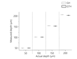
- FIG. 8A is a graph illustrating an example of depth coordinates of a sample obtained based on a holographic image (GH) and an actual holographic image (GTH) generated by the digital holography apparatus 100, and it is confirmed that the depth coordinates are similarly detected.
- GH holographic image
- GTH actual holographic image
- the digital holography apparatus 100 may detect an object existing in a 3D space based on 3D information of the detected sample. For example, the digital holography apparatus 100 may detect the location of fine dust, red blood cells, and/or platelets, etc. based on 3D information of the detected sample.
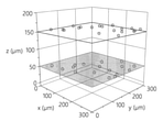
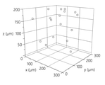
- 8B and 8C show examples of detecting a sample existing in one plane and a sample randomly spread in a three-dimensional (3D) space in a hologram converted from an optical image through the digital holography apparatus 100, respectively.
- FIG. 9A is a view showing a light scattering pattern of a sample obtained based on each of a holographic image generated by the digital holographic apparatus shown in FIG. 1 and an actual holographic image
- FIG. 9B is a light scattering pattern of disc red blood cells and polarized red blood cells. It is a drawing showing an example.
- the digital holography apparatus 100 may acquire a light scattering pattern by accumulating light intensity distributions at various depths in the depth direction.
- a light scattering pattern indicates how light diverges and converges as it passes through a sample, and the light scattering pattern may vary depending on the shape and optical characteristics of the sample.
- FIG. 9A shows an example of a light scattering pattern of polystyrene (PS) particles obtained based on the holographic image GH and the actual holographic image GT generated by the digital holography apparatus 100 .
- PS polystyrene
- FIG. 9B shows an example of light scattering patterns of disk red blood cells (DC) and polarized red blood cells (EC) particles obtained based on the holographic image (GH) and the actual holographic image (GT) generated by the digital holographic apparatus 100 .
- the digital holography apparatus 100 may classify a sample based on a scattering pattern of light obtained from the generated holographic image and detect an alteration. For example, the digital holography apparatus 100 may analyze a light scattering pattern to extract classification features such as a real focal length f r and an imaginary focal length f v of the sample.
- the classification features extracted by the digital holography apparatus 100 may be used for disease diagnosis and defect detection to improve diagnosis and detection accuracy.
- the digital holography apparatus 100 may generate a holographic image from an optical image of a general white light-based sample by using deep learning.
- the digital holographic apparatus 100 can acquire a holographic image of a sample using general white light without expensive lasers or optical components, and thus can acquire three-dimensional information of the sample with a simplified digital holographic microscope (DHM) configuration.
- DHM digital holographic microscope
- the digital holography apparatus 100 can dramatically improve the accuracy of disease diagnosis using optical images and detection of contaminants and surface defects, and can be usefully used in basic scientific research such as three-dimensional dynamic behavior analysis of particles and cells. have.
- the digital holography apparatus 100 may measure the type and concentration distribution of fine particles including fine dust and/or contaminants, and the digital holography apparatus 100 may measure the three-dimensional dynamics of blood cells and/or cells. It can be used for behavior analysis and disease diagnosis, and the digital holography apparatus 100 can also be used to measure surface characteristics such as roughness or surface defects of an object's surface.
- the method according to the embodiment may be implemented in the form of program instructions that can be executed through various computer means and recorded in a computer-readable medium.
- the computer-readable medium may include program instructions, data files, data structures, etc. alone or in combination.
- the program instructions recorded on the medium may be specially designed and configured for the embodiment, or may be known and available to those skilled in the art of computer software.
- Examples of the computer-readable recording medium include magnetic media such as hard disks, floppy disks and magnetic tapes, optical media such as CD-ROMs and DVDs, and magnetic such as floppy disks.
- - includes magneto-optical media, and hardware devices specially configured to store and execute program instructions, such as ROM, RAM, flash memory, and the like.
- Examples of program instructions include not only machine language codes such as those generated by a compiler, but also high-level language codes that can be executed by a computer using an interpreter or the like.
- the hardware devices described above may be configured to operate as one or more software modules to perform the operations of the embodiments, and vice versa.
- Software may comprise a computer program, code, instructions, or a combination of one or more thereof, which configures a processing device to operate as desired or is independently or collectively processed You can command the device.
- the software and/or data may be any kind of machine, component, physical device, virtual equipment, computer storage medium or apparatus, to be interpreted by or to provide instructions or data to the processing device. , or may be permanently or temporarily embody in a transmitted signal wave.
- the software may be distributed over networked computer systems and stored or executed in a distributed manner. Software and data may be stored in one or more computer-readable recording media.
Landscapes
- Engineering & Computer Science (AREA)
- Physics & Mathematics (AREA)
- Theoretical Computer Science (AREA)
- General Physics & Mathematics (AREA)
- Computing Systems (AREA)
- Biophysics (AREA)
- Life Sciences & Earth Sciences (AREA)
- Computational Linguistics (AREA)
- Data Mining & Analysis (AREA)
- Evolutionary Computation (AREA)
- General Health & Medical Sciences (AREA)
- Molecular Biology (AREA)
- Artificial Intelligence (AREA)
- General Engineering & Computer Science (AREA)
- Biomedical Technology (AREA)
- Mathematical Physics (AREA)
- Software Systems (AREA)
- Health & Medical Sciences (AREA)
- Computer Vision & Pattern Recognition (AREA)
- Chemical & Material Sciences (AREA)
- Analytical Chemistry (AREA)
- Optics & Photonics (AREA)
- Image Analysis (AREA)
- Holo Graphy (AREA)
Abstract
머신 러닝 기반 디지털 홀로그래피 장치 및 이의 동작 방법이 개시된다. 일 실시예에 따른 디지털 홀로그래피 방법은, 시료에 대한 2차원 정보를 포함하는 광학 영상을 획득하는 단계와, 상기 광학 영상에 기초하여 상기 시료에 대한 3차원 정보를 포함하는 홀로그램 영상을 생성하는 단계를 포함한다.
Description
실시예들은 머신 러닝 기반 디지털 홀로그래피 장치 및 이의 동작 방법에 관한 것이다.
백색광을 사용하는 광학 현미경(Bright-field microscopy)은 산업, 생물학, 의학 분야를 포함한 다양한 영역에서 널리 사용되는 영상 기술이다. 광학 영상(bright-field image)은 일반적으로 오염물질, 미생물, 생체 시료와 같은 미세 물체를 관찰하는데 사용된다. 그러나 광학 영상은 수 μm의 얇은 초점 심도(depth of focus) 내 시료의 2차원 빛의 세기 정보만 제공하기 때문에, 검출 및 진단 정확도가 보통 90% 이하로 높지 않고, 3차원 공간 형태로 존재하는 시료를 검출하기 어렵다.
결맞음성(coherent) 빛을 시료에 조사하면, 시료에 의해 회절된 물질파와 참조파의 간섭으로 홀로그램이 생성되며, 생성된 홀로그램에는 시료의 3D 영상정보가 2D 간섭무늬 형태로 담겨있다. 즉, 디지털 홀로그래픽 현미경(digital holography microscope(DHM)) 기법은 한 장의 홀로그램 영상으로부터 3D 공간 내에 존재하는 시료들의 3D 위치 및 형상 정보와 함께 광학 정보를 획득할 수 있는 영상기술이다. 이러한 DHM 기법은 별도의 라벨링 및 기계적 스캐닝 과정 없이 홀로그램으로부터 시료의 3D 정보를 비침습적으로 획득할 수 있기 때문에 생체 시료, 오염물질의 모니터링, 입자 및 세포의 3D 동적거동 분석 등 다양한 분야에서 응용되어 왔다.
홀로그램을 얻기 위해서 일반적으로 고가의 결맞음성이 좋은 레이저 광원, 고품질의 공간 필터, 거울, 렌즈 등 같은 값비싼 광학 부품들이 요구된다. 최근에는 DHM 기법에 딥러닝을 적용하여 홀로그램의 공간 해상도를 향상시키고, 수치적 재생 과정과 위상 정보 복원 알고리즘을 개선하여 생체 시료의 분류 및 모니터링 분야에 응용되고 있다. 그러나 근본적인 DHM 기법의 기술적 한계인 고가의 레이저 및 광학 부품을 대체하는 기술은 아직까지 제시된 적이 없다.
아래 실시예들은 머신 러닝을 이용하여 백색광 기반의 광학 영상을 홀로그램 영상으로 변환시켜 시료의 3차원 정보를 획득하는 기술을 제공할 수 있다.
다만, 기술적 과제는 상술한 기술적 과제들로 한정되는 것은 아니며, 또 다른 기술적 과제들이 존재할 수 있다.
일 실시예에 따른 디지털 홀로그래피 방법은, 시료에 대한 2차원 정보를 포함하는 광학 영상을 획득하는 단계와, 상기 광학 영상에 기초하여 상기 시료에 대한 3차원 정보를 포함하는 홀로그램 영상을 생성하는 단계를 포함한다.
상기 광학 영상은, 상기 시료에 백색광을 비추어 촬영한 영상일 수 있다.
상기 생성하는 단계는, 상기 광학 영상을 뉴럴 네트워크에 입력하여 상기 홀로그램 영상을 생성하는 단계를 포함할 수 있다.
상기 뉴럴 네트워크는, 동일한 시료에 백색광 및 단색광을 동시에 비추어 획득한 광학 영상 및 홀로그램 영상에 기초하여 학습된 뉴럴 네트워크일 수 있다.
상기 디지털 홀로그래피 방법은, 상기 홀로그램 영상을 깊이 방향으로 수치적으로 재생(numerical reconstruction)한 영상을 한 평면에 투영시켜 상기 시료의 2차원 위치 정보를 획득하는 단계를 포함할 수 있다.
상기 디지털 홀로그래피 방법은, 상기 홀로그램 영상을 깊이 방향으로 수치적으로 재생(numerical reconstruction)한 영상을 상기 시료의 중심을 기준으로 분할하는 단계와, 분할한 영상의 선명도에 기초하여 상기 시료의 초점 평면 영상 및 상기 시료의 깊이 정보를 획득하는 단계를 포함할 수 있다.
상기 디지털 홀로그래피 방법은, 깊이 방향으로 상기 홀로그램 영상의 빛 강도 분포를 축적하여 빛의 산란 패턴을 획득하는 단계와, 상기 빛의 산란 패턴에 기초하여 상기 시료의 실초점 거리 및 허초점 거리 중 적어도 하나를 추출하는 단계를 포함할 수 있다.
일 실시예에 따른 디지털 홀로그래피 장치는, 인스트럭션들을 포함하는 메모리와, 상기 인스트럭션들을 실행하기 위한 프로세서를 포함하고, 상기 프로세서에 의해 상기 인스트럭션들이 실행될 때, 상기 프로세서는, 시료에 대한 2차원 정보를 포함하는 광학 영상에 기초하여 상기 시료에 대한 3차원 정보를 포함하는 홀로그램 영상을 생성한다.
상기 광학 영상은, 백색광을 상기 시료에 비추어 촬영한 광학 영상일 수 있다.
상기 프로세서는, 동일한 시료에 백색광 및 단색광을 동시에 비추어 획득한 광학 영상 및 홀로그램 영상에 기초하여 학습할 수 있다.
상기 프로세서는, 상기 홀로그램 영상을 깊이 방향으로 수치적으로 재생(numerical reconstruction)한 영상을 한 평면에 투영시켜 상기 시료의 2차원 위치 정보를 획득할 수 있다.
상기 프로세서는, 상기 홀로그램 영상을 깊이 방향으로 수치적으로 재생(numerical reconstruction)한 영상을 상기 시료의 중심을 기준으로 분할하고, 분할한 영상의 선명도에 기초하여 상기 시료의 깊이 정보를 획득할 수 있다.
상기 프로세서는, 깊이 방향으로 상기 홀로그램 영상의 빛 강도 분포를 축적하여 빛의 산란 패턴을 획득하고, 상기 빛의 산란 패턴에 기초하여 상기 시료의 실초점 거리 및 허초점 거리 중 적어도 하나를 추출할 수 있다.
일 실시예에 따른 디지털 홀로그래피 장치의 학습 방법은, 동일한 시료에 백색광 및 단색광을 동시에 비추어 획득한 광학 영상 및 제1 홀로그램 영상을 획득하는 단계와, 제1 뉴럴 네트워크를 통해 상기 광학 영상에 기초하여 제2 홀로그램 영상을 생성하는 단계와, 제2 뉴럴 네트워크를 통해 상기 제1 홀로그램 영상 및 상기 제2 홀로그램 영상의 진위를 평가하는 단계와, 상기 제1 홀로그램 영상, 상기 제2 홀로그램 영상 및 진위 평가 결과에 기초한 손실 함수를 최적화하는 단계를 포함한다.
상기 손실 함수는, 상기 제1 뉴럴 네트워크에 대한 제1 손실 함수 및 상기 제2 뉴럴 네트워크에 대한 제2 손실 함수를 포함하고, 상기 최적화하는 단계는, 상기 제1 손실 함수 및 제2 손실 함수가 각각 최소 값을 가지도록 상기 제1 뉴럴 네트워크 및 제2 뉴럴 네트워크의 가중치를 조절하는 단계를 포함할 수 있다.
일 실시예에 따른 디지털 홀로그래피 장치는, 인스트럭션들을 포함하는 메모리와, 상기 인스트럭션들을 실행하기 위한 프로세서를 포함하고, 상기 프로세서에 의해 상기 인스트럭션들이 실행될 때, 상기 프로세서는, 동일한 시료에 백색광 및 단색광을 동시에 비추어 획득한 광학 영상 및 제1 홀로그램 영상을 획득하고, 제1 뉴럴 네트워크를 통해 상기 광학 영상에 기초하여 제2 홀로그램 영상을 생성하고, 제2 뉴럴 네트워크를 통해 상기 제1 홀로그램 영상 및 상기 제2 홀로그램 영상의 진위를 평가하고, 상기 제1 홀로그램 영상, 상기 제2 홀로그램 영상 및 진위 평가 결과에 기초한 손실 함수를 최적화한다.
상기 손실 함수는, 상기 제1 뉴럴 네트워크에 대한 제1 손실 함수 및 상기 제2 뉴럴 네트워크에 대한 제2 손실 함수를 포함하고, 상기 프로세서는, 상기 제1 손실 함수 및 제2 손실 함수가 각각 최소 값을 가지도록 상기 제1 뉴럴 네트워크 및 제2 뉴럴 네트워크의 가중치를 조절할 수 있다.
도 1은 일 실시예에 따른 디지털 홀로그래피 장치를 개략적으로 나타내는 블록도이다.
도 2는 도 1에 도시된 디지털 홀로그래피 장치를 학습시키기 위한 학습 데이터를 생성하는 하이브리드 영상 장치를 나타내는 도면이다.
도 3a 및 도 3b는 도 2에 도시된 하이브리드 영상 장치가 생성한 학습 데이터를 나타내는 도면이다.
도 4는 도 1에 도시된 디지털 홀로그래피 장치가 포함하는 네트워크 구조를 나타내는 도면이다.
도 5는 도 1에 도시된 디지털 홀로그래피 장치가 생성한 홀로그램 영상을 나타내는 도면이다.
도 6은 도 1에 도시된 디지털 홀로그래피 장치가 생성한 홀로그램 영상을 수치적으로 재생하여 획득한 초점 평면 영상을 나타내는 도면이다.
도 7a 내지 7c는 실제 홀로그램 영상 및 도 1에 도시된 디지털 홀로그래피 장치가 생성한 홀로그램 영상 각각에 기초하여 획득한 시료의 2차원 정보를 비교하기 위한 도면이다.
도 8a 내지 도 8c는 실제 홀로그램 영상 및 도 1에 도시된 디지털 홀로그래피 장치가 생성한 홀로그램 영상 각각에 기초하여 획득한 시료의 3차원 정보를 비교하기 위한 도면이다.
도 9a 및 도 9b는 도 1에 도시된 디지털 홀로그래피 장치가 생성한 홀로그램 영상 및 실제 홀로그램 영상 각각에 기초하여 획득한 시료의 빛 산란 패턴을 나타내는 도면이다.
이하에서, 첨부된 도면을 참조하여 실시예들을 상세하게 설명한다. 그러나, 실시예들에는 다양한 변경이 가해질 수 있어서 특허출원의 권리 범위가 이러한 실시예들에 의해 제한되거나 한정되는 것은 아니다. 실시예들에 대한 모든 변경, 균등물 내지 대체물이 권리 범위에 포함되는 것으로 이해되어야 한다.
실시예에서 사용한 용어는 단지 설명을 목적으로 사용된 것으로, 한정하려는 의도로 해석되어서는 안된다. 단수의 표현은 문맥상 명백하게 다르게 뜻하지 않는 한, 복수의 표현을 포함한다. 본 명세서에서, "포함하다" 또는 "가지다" 등의 용어는 명세서 상에 기재된 특징, 숫자, 단계, 동작, 구성요소, 부품 또는 이들을 조합한 것이 존재함을 지정하려는 것이지, 하나 또는 그 이상의 다른 특징들이나 숫자, 단계, 동작, 구성요소, 부품 또는 이들을 조합한 것들의 존재 또는 부가 가능성을 미리 배제하지 않는 것으로 이해되어야 한다.
다르게 정의되지 않는 한, 기술적이거나 과학적인 용어를 포함해서 여기서 사용되는 모든 용어들은 실시예가 속하는 기술 분야에서 통상의 지식을 가진 자에 의해 일반적으로 이해되는 것과 동일한 의미를 가지고 있다. 일반적으로 사용되는 사전에 정의되어 있는 것과 같은 용어들은 관련 기술의 문맥 상 가지는 의미와 일치하는 의미를 가지는 것으로 해석되어야 하며, 본 출원에서 명백하게 정의하지 않는 한, 이상적이거나 과도하게 형식적인 의미로 해석되지 않는다.
또한, 첨부 도면을 참조하여 설명함에 있어, 도면 부호에 관계없이 동일한 구성 요소는 동일한 참조부호를 부여하고 이에 대한 중복되는 설명은 생략하기로 한다. 실시예를 설명함에 있어서 관련된 공지 기술에 대한 구체적인 설명이 실시예의 요지를 불필요하게 흐릴 수 있다고 판단되는 경우 그 상세한 설명을 생략한다.
또한, 실시 예의 구성 요소를 설명하는 데 있어서, 제 1, 제 2, A, B, (a), (b) 등의 용어를 사용할 수 있다. 이러한 용어는 그 구성 요소를 다른 구성 요소와 구별하기 위한 것일 뿐, 그 용어에 의해 해당 구성 요소의 본질이나 차례 또는 순서 등이 한정되지 않는다. 어떤 구성 요소가 다른 구성요소에 "연결", "결합" 또는 "접속"된다고 기재된 경우, 그 구성 요소는 그 다른 구성요소에 직접적으로 연결되거나 접속될 수 있지만, 각 구성 요소 사이에 또 다른 구성 요소가 "연결", "결합" 또는 "접속"될 수도 있다고 이해되어야 할 것이다.
어느 하나의 실시 예에 포함된 구성요소와, 공통적인 기능을 포함하는 구성요소는, 다른 실시 예에서 동일한 명칭을 사용하여 설명하기로 한다. 반대되는 기재가 없는 이상, 어느 하나의 실시 예에 기재한 설명은 다른 실시 예에도 적용될 수 있으며, 중복되는 범위에서 구체적인 설명은 생략하기로 한다.
도 1은 일 실시예에 따른 디지털 홀로그래피 장치를 개략적으로 나타내는 블록도이다.
디지털 홀로그래피 장치(100)는 시료에 대한 불충분한 정보를 제공하는 종래의 광학 현미경과 정교한 평행광이 필요한 디지털 홀로그래피 현미경(digital holography microscopy(DHM))의 기술적 한계를 극복하기 위하여 머신 러닝을 이용할 수 있다.
디지털 홀로그래피 장치(100)는 백색광을 이용하여 시료의 3차원 정보를 획득하고, 3차원 정보에 기초하여 시료를 검출할 수 있다. 예를 들어, 디지털 홀로그래피 장치(100)는 시료에 백색광을 비추어 촬영한 광학 영상(bright-light(BF) image)에 기초하여 시료의 3차원 정보를 획득할 수 있다. 이때 백색광은 할로겐 램프(halogen lamps), LED 램프, 스마트폰 플래시 등을 포함할 수 있다.
디지털 홀로그래피 장치(100)는 백색광을 이용하여 촬영한 시료의 광학 영상에 기초하여 시료의 홀로그램 영상을 생성할 수 있다. 예를 들어, 디지털 홀로그래피 장치(100)는 시료에 대한 2차원 정보를 포함하는 광학 영상을 시료에 대한 3차원 정보까지 포함하는 홀로그램 영상으로 변환할 수 있다.
디지털 홀로그래피 장치(100)는 생성한 홀로그램 영상으로부터 시료의 3차원 정보를 추출할 수 있다. 예를 들어, 디지털 홀로그래피 장치(100)는 빛의 확산 공식을 적용하여 여러 깊이에서 홀로그램 영상을 수치적으로 재생(numerical reconstruction)하여 시료의 3차원 정보를 획득할 수 있다.
디지털 홀로그래피 장치(100)는 뉴럴 네트워크(neural network)을 이용하여 특정 깊이에 위치한 시료의 초점이 맞지 않는(defocused) 광학 영상을 이와 동등한 홀로그램 영상으로 변환시켜, 값비싼 광학 부품을 사용하지 않고 백색광을 이용하여 시료의 3D 정보를 획득하고, 이를 시료 검출에 활용할 수 있다.
뉴럴 네트워크는 심층뉴럴 네트워크(Deep Neural Network)를 포함할 수 있다. 뉴럴 네트워크는 CNN(Convolutional Neural Network), RNN(Recurrent Neural Network), 퍼셉트론(perceptron), FF(Feed Forward), RBF(Radial Basis Network), DFF(Deep Feed Forward), LSTM(Long Short Term Memory), GRU(Gated Recurrent Unit), AE(Auto Encoder), VAE(Variational Auto Encoder), DAE(Denoising Auto Encoder), SAE(Sparse Auto Encoder), MC(Markov Chain), HN(Hopfield Network), BM(Boltzmann Machine), RBM(Restricted Boltzmann Machine), DBN(Depp Belief Network), DCN(Deep Convolutional Network), DN(Deconvolutional Network), DCIGN(Deep Convolutional Inverse Graphics Network), GAN(Generative Adversarial Network), LSM(Liquid State Machine), ELM(Extreme Learning Machine), ESN(Echo State Network), DRN(Deep Residual Network), DNC(Differentiable Neural Computer), NTM(Neural Turning Machine), CN(Capsule Network), KN(Kohonen Network) 및 AN(Attention Network)를 포함할 수 있다.
디지털 홀로그래피 장치(100)는 메모리(110) 및 프로세서(150)를 포함할 수 있다.
메모리(110)는 프로세서(150)에 의해 실행가능한 인스트럭션들(또는 프로그램)을 저장할 수 있다. 예를 들어, 인스트럭션들은 프로세서(150)의 동작 및/또는 프로세서(150)의 각 구성의 동작을 실행하기 위한 인스트럭션들을 포함할 수 있다.
메모리(110)는 휘발성 메모리 장치 또는 불휘발성 메모리 장치로 구현될 수 있다.
휘발성 메모리 장치는 DRAM(dynamic random access memory), SRAM(static random access memory), T-RAM(thyristor RAM), Z-RAM(zero capacitor RAM), 또는 TTRAM(Twin Transistor RAM)으로 구현될 수 있다.
불휘발성 메모리 장치는 EEPROM(Electrically Erasable Programmable Read-Only Memory), 플래시(flash) 메모리, MRAM(Magnetic RAM), 스핀전달토크 MRAM(Spin-Transfer Torque(STT)-MRAM), Conductive Bridging RAM(CBRAM), FeRAM(Ferroelectric RAM), PRAM(Phase change RAM), 저항 메모리(Resistive RAM(RRAM)), 나노 튜브 RRAM(Nanotube RRAM), 폴리머 RAM(Polymer RAM(PoRAM)), 나노 부유 게이트 메모리(Nano Floating Gate Memory(NFGM)), 홀로그래픽 메모리(holographic memory), 분자 전자 메모리 소자(Molecular Eelectronic Memory Device), 또는 절연 저항 변화 메모리(Insulator Resistance Change Memory)로 구현될 수 있다.
프로세서(150)는 메모리(110)에 저장된 데이터를 처리할 수 있다. 프로세서(150)는 메모리(110)에 저장된 컴퓨터로 읽을 수 있는 코드(예를 들어, 소프트웨어) 및 프로세서(150)에 의해 유발된 인스트럭션(instruction)들을 실행할 수 있다.
프로세서(150)는 목적하는 동작들(desired operations)을 실행시키기 위한 물리적인 구조를 갖는 회로를 가지는 하드웨어로 구현된 데이터 처리 장치일 수 있다. 예를 들어, 목적하는 동작들은 프로그램에 포함된 코드(code) 또는 인스트럭션들(instructions)을 포함할 수 있다.
예를 들어, 하드웨어로 구현된 데이터 처리 장치는 마이크로프로세서(microprocessor), 중앙 처리 장치(central processing unit), 프로세서 코어(processor core), 멀티-코어 프로세서(multi-core processor), 멀티프로세서(multiprocessor), ASIC(Application-Specific Integrated Circuit), FPGA(Field Programmable Gate Array)를 포함할 수 있다.
도 2는 도 1에 도시된 디지털 홀로그래피 장치를 학습시키기 위한 학습 데이터를 생성하는 하이브리드 영상 장치를 나타내는 도면이고, 도 3a 및 도 3b는 도 2에 도시된 하이브리드 영상 장치가 생성한 학습 데이터를 나타내는 도면이다.
하이브리드 영상 장치(200)는 디지털 홀로그래피 장치(100)의 학습에 이용되는 학습 데이터를 생성할 수 있다. 예를 들어, 하이브리드 영상 장치(200)는 시료의 광학 영상 및 광학 영상에 대응되는 홀로그램 영상을 획득할 수 있다.
하이브리드 영상 장치(200)는 제1 카메라(210), 제2 카메라(220), 이색성 거울(dichroic mirror)(230), 대물 렌즈(240) 및 미세 채널(250)을 포함할 수 있다.
하이브리드 영상 장치(200)는 미세 채널(250)을 통과하는 시료에 백색광 및 단색광을 동시에 비출 수 있다. 이때, 단색광은 공간 필터(spatial filter)를 거친 레이저 평행광일 수 있다.
미세 채널(250)은 주입 및 분리 부분을 가지는 복수의 미세 채널로 구성될 수 있다. 미세 채널(250)을 통해 시료가 흘러 지나갈 수 있으며, 백색광 및 단색광이 미세 채널(250)을 흘러지나는 시료를 비출 수 있다.
대물 렌즈(240)는 미세 채널(250)에 백색광 및 단색광을 비추어 획득한 광학 영상 및 홀로그램 영상을 확대할 수 있다. 대물 렌즈(240)는 튜브 렌즈(tube lens)를 포함할 수 있다.
이색성 거울(230)은 특정 파장대의 빛은 반사하고 나머지 빛들은 통과시킬 수 있다. 즉, 이색성 거울(230)은 빛의 파장에 따라 빛을 투과 또는 반사시킬 수 있다. 이색성 거울(230)은 단색광을 제2 카메라(220) 방향으로 반사시키고, 백색광을 제1 카메라(210) 방향으로 통과시킬 수 있다.
제1 카메라(210)는 백색광에 의한 광학 영상을 획득할 수 있다. 예를 들어, 제1 카메라(210)는 도 3a에 도시된 것과 같은 시료의 광학 영상을 획득할 수 있다.
제2 카메라(220)는 단색광에 의한 홀로그램 영상을 획득할 수 있다. 예를 들어, 제2 카메라(220)는 도 3b에 도시된 것과 같은 시료의 홀로그램 영상을 획득할 수 있다.
제1 카메라(210) 및 제2 카메라(220)는 CCD(charge coupled device) 카메라 또는 CMOS(complementary metal oxide semiconductor) 카메라일 수 있다.
하이브리드 영상 장치(200)가 획득한 시료의 광학 영상 및 홀로그램 영상은 디지털 홀로그래피 장치(100)의 학습 데이터로 이용될 수 있다. 디지털 홀로그래피 장치(100)는 동일한 시료에 대한 광학 영상 및 홀로그램 영상을 학습할 수 있다.
도 4는 도 1에 도시된 디지털 홀로그래피 장치가 포함하는 네트워크 구조를 나타내는 도면이고, 도 5는 도 1에 도시된 디지털 홀로그래피 장치가 생성한 홀로그램 영상을 나타내는 도면이다.
디지털 홀로그래피 장치(100)는 생성적 적대 신경망(generative adversarial network(GAN))을 포함할 수 있다. 예를 들어, 디지털 홀로그래피 장치(100)는 GAN(400)을 이용하여 광학 영상을 홀로그램 영상으로 변환할 수 있다.
GAN(400)은 하이브리드 영상 장치(200)에 의해 생성된 학습 데이터에 기초하여 학습할 수 있다. 백색광을 이용하여 획득한 광학 영상의 경우, 대물 렌즈의 배율에 따른 초점 심도로 인해 시료의 깊이 좌표가 증가할수록 신호의 세기가 약해지고 흐릿해질 수 있다. 결맞음성 빛을 비추어 시료에 의해 회절된 물질파와 시료를 통과하지 않은 참조파의 간섭현상으로 형성된 홀로그램 영상의 경우, 시료의 깊이 좌표가 증가할수록 간섭 무늬 간격이 증가한다. GAN(400)은 깊이에 따른 시료의 광학 영상 및 광학 영상에 대응하는 홀로그램 영상 사이의 관계를 통계적으로 학습할 수 있다.
GAN(400)은 제1 뉴럴 네트워크(410) 및 제2 뉴럴 네트워크(430)를 포함할 수 있다. 예를 들어, 제1 뉴럴 네트워크(410)는 생성 모델(generator)(410)일 수 있고, 제2 뉴럴 네트워크(430)는 분류 모델(discriminator)(430)일 수 있다.
생성 모델(410)은 입력 영상에 기초하여 새로운 영상을 생성할 수 있다. 예를 들어, 생성 모델(410)은 학습 영상 중 광학 영상에 기초하여 광학 영상에 대응되는 홀로그램 영상을 생성할 수 있다. 생성 모델(410)은 광학 영상 내에 존재하는 간섭 무늬와 같은 다층 구조를 학습하여, 홀로그램 영상을 생성할 수 있는 CNN(convolutional neural network)를 변형한 네트워크 구조를 가질 수 있다.
도 4에서 특징 맵(feature map) 또는 뉴런(neuron)의 수는 생성 모델(410) 및 판별 모델(430)의 왼쪽에 표시된 값일 수 있다. 특징 맵의 크기는 생성 모델(410) 및 판별 모델(430)의 오른쪽에 표시된 값일 수 있다. 서로 다른 색상의 화살표는 각각의 유형의 연결을 나타낼 수 있다. 색상이 다른 두 블록의 병합은 특징 맵의 연결을 나타낼 수 있다.
분류 모델(430)은 생성 모델(410)이 생성한 홀로그램 영상 및/또는 학습 영상을 획득한 홀로그램 영상의 진위 여부를 평가할 수 있다. 예를 들어, 분류 모델(430)은 실제 홀로그램 영상과 생성된 홀로그램 영상의 진위 여부를 판단하여, 실제 원본인 홀로그램 영상일 확률이 높다고 판단할 경우 1에 가까운 값을 출력하고, 생성된 홀로그램 영상일 확률이 높다고 판단하는 경우 0에 가까운 값을 출력하는 CNN일 수 있다.
GAN(400)은 학습 과정에서 생성 모델(410) 및 분류 모델(430)의 서로 반대되는 손실 함수(loss function)의 최적화를 시도할 수 있다. 예를 들어, 생성 모델(410)은 분류 모델(430)이 실제 홀로그램 영상과 생성된 홀로그램 영상을 분류할 수 없도록 학습하고, 분류 모델(430)은 분류에 성공할 확률을 높일 수 있도록 서로 적대적으로 학습할 수 있다.
생성 모델(410)의 손실 함수(L
G) 및 분류 모델(430)의 손실 함수(L
D)는 각각 수학식 1 및 수학식 2와 같이 표현될 수 있다.

G(I) 및 GT(I)는 각각 생성된 홀로그램 영상과 실제 홀로그램 영상을 나타내고, D(G(I))와 D(GT(I))는 생성된 홀로그램 영상과 실제 홀로그램 영상들을 분류 모델(430)에 입력했을 때 출력되는 값을 의미하고, MSE(X,Y) 및 BCE(x,y)는 각각 수학식 3 및 수학식 4와 같이 표현될 수 있다.

이때, MSE(X,Y)에서 X
i,j 및 Y
i,j는 각각 영상 X 및 Y의 픽셀 (i,j)의 값을 의미하고, n
x 및 n
y는 X 및 Y 영상의 x 축 및 y 축 방향의 영상 픽셀 수를 의미한다. BCE(x,y)에서 x 및 y는 각각 0 이상 1 이하의 값이다.
GAN(400)은 생성 모델(410)의 손실 함수(L
G) 및 분류 모델(430)의 손실 함수(L
D)가 각각 최소가 되도록 생성 모델(410) 및 분류 모델(430)을 학습할 수 있다. 예를 들어, GAN(400)은 손실 함수(L
G) 및 분류 모델(430)의 손실 함수(L
D)가 각각 최소가 되도록 생성 모델(410) 및 분류 모델(430) 각각의 가중치를 조절할 수 있다.
디지털 홀로그래피 장치(100)는 광학 영상(510)을 홀로그램 영상(530)으로 변환할 수 있다. 예를 들어, 디지털 홀로그래피 장치(100)는 학습된 생성 모델(410)을 통해 홀로그램 영상(530)을 생성할 수 있다.
홀로그램 영상(530)은 실제 홀로그램 영상(550)과 비교하여 유사하게 생성될 것을 확인할 수 있고, 실제 홀로그램 영상(550)에 비해 노이즈가 감소함을 확인할 수 있다.
도 6은 도 1에 도시된 디지털 홀로그래피 장치가 생성한 홀로그램 영상을 수치적으로 재생하여 획득한 초점 평면 영상을 나타내는 도면이다.
디지털 홀로그래피 장치(100)는 생성한 홀로그램 영상에 기초하여 3차원 정보를 추출할 수 있다. 디지털 홀로그래피 장치(100)는 홀로그램 영상을 광축 방향으로 수치적으로 재생(numerical reconstruction)할 수 있다. 이때, 광축 방향은 영상의 깊이 방향일 수 있다.
광축 방향에 수직한 평면의 복소 웨이브 필드(complex wavefield;
 )는 수학식 5와 같이 표현할 수 있다.

수학식 5에서, F는 고속 푸리에 변환, F
-1은 역 고속 푸리에 변환, (x,y)는 홀로그램 영상 평면의 좌표계,
 는 재생된 영상 평면의 좌표계, h(x,y,0)는 홀로그램 영상 정보, z는 깊이 방향 거리,
 는 매질 내 빛의 파장, M은 영상의 x 방향 픽셀 수, m = 0, 1,
 , M-1, N은 영상의 y 방향 픽셀 수, n = 0, 1,
 , N-1,
 와
와
 는 각각 영상 내 x 및 y 방향의 픽셀 크기를 나타낸다.
디지털 홀로그래피 장치(100)는 홀로그램 영상을 수치적으로 재생(numerical reconstruction)하여 홀로그램 영상의 복소 웨이브 필드 정보를 획득할 수 있고, 복소 웨이브 필드 정보에 기초하여 시료의 2차원 및/또는 3차원 정보를 추출할 수 있다.
디지털 홀로그래피 장치(100)는 홀로그램 영상을 수치적으로 재생(numerical reconstruction)하여 시료의 초점 평면 영상(in-focus image)을 획득할 수 있다.
도 7a 내지 7c는 실제 홀로그램 영상 및 도 1에 도시된 디지털 홀로그래피 장치가 생성한 홀로그램 영상 각각에 기초하여 획득한 시료의 2차원 정보를 비교하기 위한 도면이다.
디지털 홀로그래피 장치(100)는 시료의 2차원 위치 정보를 획득할 수 있다. 디지털 홀로그래피 장치(100)는 생성한 홀로그램 영상을 수치적으로 재생한 영상을 하나의 영상 평면에 투영시켜 시료의 중심에 렌즈 효과로 인한 국부적인 강한 피크를 생성할 수 있다. 디지털 홀로그래피 장치(100)는 생성한 피크에 기초하여 시료의 2차원 위치 좌표를 획득할 수 있다.
도 7a는 디지털 홀로그래피 장치(100)가 생성된 홀로그램 영상으로부터 획득한 시료의 2차원 좌표를 나타내고, 도 7b는 실제 홀로그램 영상으로부터 획득한 시료의 2차원 좌표를 나타낸다. 도 7c를 참조하면, 디지털 홀로그래피 장치(100)는 실제 홀로그램 영상과 유사하게 시료의 2차원 좌표를 획득할 수 있음을 확인할 수 있다.
도 8a 내지 도 8c는 실제 홀로그램 영상 및 도 1에 도시된 디지털 홀로그래피 장치가 생성한 홀로그램 영상 각각에 기초하여 획득한 시료의 3차원 정보를 비교하기 위한 도면이다.
디지털 홀로그래피 장치(100)는 시료의 깊이 정보를 획득할 수 있다. 예를 들어, 디지털 홀로그래피 장치(100)는 생성한 홀로그램 영상을 수치적으로 재생한 영상을 각각의 시료의 중심을 기준을 분할하고, 영상 선명도에 기초하여 시료의 깊이 좌표를 획득할 수 있다.
도 8a는 디지털 홀로그래피 장치(100)가 생성한 홀로그램 영상(GH) 및 실제 홀로그램 영상(GTH)에 기초하여 획득한 시료의 깊이 좌표의 일 예를 나타내는 그래프이고, 서로 유사하게 깊이 좌표를 검출됨을 확인할 수 있다.
디지털 홀로그래피 장치(100)는 검출한 시료의 3차원 정보에 기초하여 3차원 공간 내부에 존재하는 물체를 검출할 수 있다. 예를 들어, 디지털 홀로그래피 장치(100)는 검출한 시료의 3차원 정보에 기초하여 미세 먼지, 적혈구 및/또는 혈소판 등을 위치를 검출할 수 있다.
도 8b 및 도 8c는 각각 디지털 홀로그래피 장치(100)를 통해 광학 영상으로부터 변환된 홀로그램에서 한 평면에 존재하는 시료 및 3차원(3D) 공간 내에 무작위로 퍼져 있는 시료를 검출하는 예를 나타낸다.
도 9a는 도 1에 도시된 디지털 홀로그래피 장치가 생성한 홀로그램 영상 및 실제 홀로그램 영상 각각에 기초하여 획득한 시료의 빛 산란 패턴을 나타내는 도면이고, 도 9b는 원판 적혈구 및 유극 적혈구의 빛 산란 패턴의 일 예를 나타내는 도면이다.
디지털 홀로그래피 장치(100)는 여러 깊이에서의 빛 강도 분포를 깊이 방향으로 축적하여 빛의 산란 패턴을 획득할 수 있다. 빛 산란 패턴(light scattering)은 빛이 시료를 지나면서 어떻게 발산하고 수렴하는지를 나타내는데, 빛의 산란 패턴은 시료의 형상과 광학적인 특성에 따라 달라질 수 있다.
도 9a는 디지털 홀로그래피 장치(100)가 생성한 홀로그램 영상(GH) 및 실제 홀로그램 영상(GT)에 기초하여 획득한 폴리스타이렌(polystyrene(PS) 입자의 빛 산란 패턴의 예를 나타낸다.
도 9b는 디지털 홀로그래피 장치(100)가 생성한 홀로그램 영상(GH) 및 실제 홀로그램 영상(GT)에 기초하여 획득한 원판 적혈구(DC) 및 유극 적혈구(EC) 입자의 빛 산란 패턴의 예를 나타낸다.
디지털 홀로그래피 장치(100)는 생성한 홀로그램영상에서 획득한 빛의 산란 패턴에 기초하여 시료를 분류(classification)하고 형상 변형(alteration)을 검출할 수 있다. 예를 들어, 디지털 홀로그래피 장치(100)는 빛의 산란 패턴을 분석하여 시료의 실초점 거리(f
r), 허초점 거리(f
v)와 같은 분류 특징들을 추출할 수 있다.
디지털 홀로그래피 장치(100)가 추출한 분류 특징들은 질병 진단 및 결함 검출에 이용되어 진단 및 검출 정확도를 향상시킬 수 있다.
디지털 홀로그래피 장치(100)는 딥러닝을 활용하여 일반적인 백색광 기반의 시료의 광학 영상으로부터 홀로그램 영상을 생성할 수 있다. 디지털 홀로그래피 장치(100)는 값비싼 레이저나 광학 부품 없이 일반적인 백색광을 사용하여 시료의 홀로그램 영상을 획득할 수 있어, 간소화된 디지털 홀로그래피 현미경(DHM) 구성으로 시료의 3차원 정보를 획득할 수 있다.
디지털 홀로그래피 장치(100)는 광학 영상을 활용한 질환 진단, 오염물질 및 표면 결함 검출 정확도를 획기적으로 개선시킬 수 있으며, 입자 및 세포의 3차원 동적거동 분석과 같은 기초과학 연구에도 유용하게 활용될 수 있다. 예를 들어, 디지털 홀로그래피 장치(100)는 미세먼지 및/또는 오염물질을 포함하는 미세 입자의 종류와 농도 분포를 측정할 수 있고, 디지털 홀로그래피 장치(100)는 혈구 및/또는 세포의 3차원 동적 거동 분석과 질병 진단에 활용될 수 있고, 디지털 홀로그래피 장치(100)는 물체 표면의 거칠기나 표면 결함과 같은 표면 특성 측정에 활용될 수도 있다.
실시예에 따른 방법은 다양한 컴퓨터 수단을 통하여 수행될 수 있는 프로그램 명령 형태로 구현되어 컴퓨터 판독 가능 매체에 기록될 수 있다. 상기 컴퓨터 판독 가능 매체는 프로그램 명령, 데이터 파일, 데이터 구조 등을 단독으로 또는 조합하여 포함할 수 있다. 상기 매체에 기록되는 프로그램 명령은 실시예를 위하여 특별히 설계되고 구성된 것들이거나 컴퓨터 소프트웨어 당업자에게 공지되어 사용 가능한 것일 수도 있다. 컴퓨터 판독 가능 기록 매체의 예에는 하드 디스크, 플로피 디스크 및 자기 테이프와 같은 자기 매체(magnetic media), CD-ROM, DVD와 같은 광기록 매체(optical media), 플롭티컬 디스크(floptical disk)와 같은 자기-광 매체(magneto-optical media), 및 롬(ROM), 램(RAM), 플래시 메모리 등과 같은 프로그램 명령을 저장하고 수행하도록 특별히 구성된 하드웨어 장치가 포함된다. 프로그램 명령의 예에는 컴파일러에 의해 만들어지는 것과 같은 기계어 코드뿐만 아니라 인터프리터 등을 사용해서 컴퓨터에 의해서 실행될 수 있는 고급 언어 코드를 포함한다. 상기된 하드웨어 장치는 실시예의 동작을 수행하기 위해 하나 이상의 소프트웨어 모듈로서 작동하도록 구성될 수 있으며, 그 역도 마찬가지이다.
소프트웨어는 컴퓨터 프로그램(computer program), 코드(code), 명령(instruction), 또는 이들 중 하나 이상의 조합을 포함할 수 있으며, 원하는 대로 동작하도록 처리 장치를 구성하거나 독립적으로 또는 결합적으로(collectively) 처리 장치를 명령할 수 있다. 소프트웨어 및/또는 데이터는, 처리 장치에 의하여 해석되거나 처리 장치에 명령 또는 데이터를 제공하기 위하여, 어떤 유형의 기계, 구성요소(component), 물리적 장치, 가상 장치(virtual equipment), 컴퓨터 저장 매체 또는 장치, 또는 전송되는 신호 파(signal wave)에 영구적으로, 또는 일시적으로 구체화(embody)될 수 있다. 소프트웨어는 네트워크로 연결된 컴퓨터 시스템 상에 분산되어서, 분산된 방법으로 저장되거나 실행될 수도 있다. 소프트웨어 및 데이터는 하나 이상의 컴퓨터 판독 가능 기록 매체에 저장될 수 있다.
이상과 같이 실시예들이 비록 한정된 도면에 의해 설명되었으나, 해당 기술분야에서 통상의 지식을 가진 자라면 상기를 기초로 다양한 기술적 수정 및 변형을 적용할 수 있다. 예를 들어, 설명된 기술들이 설명된 방법과 다른 순서로 수행되거나, 및/또는 설명된 시스템, 구조, 장치, 회로 등의 구성요소들이 설명된 방법과 다른 형태로 결합 또는 조합되거나, 다른 구성요소 또는 균등물에 의하여 대치되거나 치환되더라도 적절한 결과가 달성될 수 있다.
그러므로, 다른 구현들, 다른 실시예들 및 특허청구범위와 균등한 것들도 후술하는 청구범위의 범위에 속한다.
Claims (10)
- 시료에 대한 2차원 정보를 포함하는 광학 영상을 획득하는 단계;상기 광학 영상에 기초하여 상기 시료에 대한 3차원 정보를 포함하는 홀로그램 영상을 생성하는 단계; 및를 포함하는, 디지털 홀로그래피 방법.
- 제1항에 있어서,상기 광학 영상은,상기 시료에 백색광을 비추어 촬영한 영상인, 디지털 홀로그래피 방법.
- 제1항에 있어서,상기 생성하는 단계는,상기 광학 영상을 동일한 시료에 백색광 및 단색광을 동시에 비추어 획득한 광학 영상 및 홀로그램 영상에 기초하여 학습된 뉴럴 네트워크에 입력하여 상기 홀로그램 영상을 생성하는 단계를 포함하는, 디지털 홀로그래피 방법.
- 제1항에 있어서,상기 홀로그램 영상을 깊이 방향으로 수치적으로 재생(numerical reconstruction)하여 상기 시료에 대한 3차원 정보를 획득하는 단계를 더 포함하는, 디지털 홀로그래피 방법.
- 제1항에 있어서,깊이 방향으로 상기 홀로그램 영상의 빛 강도 분포를 축적하여 빛의 산란 패턴을 획득하는 단계; 및상기 빛의 산란 패턴에 기초하여 상기 시료의 실초점 거리 및 허초점 거리 중 적어도 하나를 추출하는 단계를 더 포함하는, 디지털 홀로그래피 방법.
- 인스트럭션들을 포함하는 메모리; 및상기 인스트럭션들을 실행하기 위한 프로세서를 포함하고,상기 프로세서에 의해 상기 인스트럭션들이 실행될 때, 상기 프로세서는,시료에 대한 2차원 정보를 포함하는 광학 영상에 기초하여 상기 시료에 대한 3차원 정보를 포함하는 홀로그램 영상을 생성하는, 디지털 홀로그래피 장치.
- 제6항에 있어서,상기 광학 영상은,백색광을 상기 시료에 비추어 촬영한 광학 영상인, 디지털 홀로그래피 장치.
- 제6항에 있어서,상기 프로세서는,동일한 시료에 백색광 및 단색광을 동시에 비추어 획득한 광학 영상 및 홀로그램 영상에 기초하여 학습하는, 디지털 홀로그래피 장치.
- 제6항에 있어서,상기 프로세서는,상기 홀로그램 영상을 깊이 방향으로 수치적으로 재생(numerical reconstruction)하여 상기 시료에 대한 3차원 정보를 획득하는, 디지털 홀로그래피 장치.
- 제6항에 있어서,상기 프로세서는,깊이 방향으로 상기 홀로그램 영상의 빛 강도 분포를 축적하여 빛의 산란 패턴을 획득하고, 상기 빛의 산란 패턴에 기초하여 상기 시료의 실초점 거리 및 허초점 거리 중 적어도 하나를 추출하는, 디지털 홀로그래피 장치.
Priority Applications (1)
| Application Number | Priority Date | Filing Date | Title |
|---|---|---|---|
| US18/015,139 US12235607B2 (en) | 2020-07-16 | 2020-08-31 | Machine learning-based digital holography device and method for operating same |
Applications Claiming Priority (2)
| Application Number | Priority Date | Filing Date | Title |
|---|---|---|---|
| KR10-2020-0088205 | 2020-07-16 | ||
| KR1020200088205A KR102410025B1 (ko) | 2020-07-16 | 2020-07-16 | 머신 러닝 기반 디지털 홀로그래피 장치 및 이의 동작 방법 |
Publications (1)
| Publication Number | Publication Date |
|---|---|
| WO2022014772A1 true WO2022014772A1 (ko) | 2022-01-20 |
Family
ID=79554784
Family Applications (1)
| Application Number | Title | Priority Date | Filing Date |
|---|---|---|---|
| PCT/KR2020/011619 Ceased WO2022014772A1 (ko) | 2020-07-16 | 2020-08-31 | 머신 러닝 기반 디지털 홀로그래피 장치 및 이의 동작 방법 |
Country Status (3)
| Country | Link |
|---|---|
| US (1) | US12235607B2 (ko) |
| KR (1) | KR102410025B1 (ko) |
| WO (1) | WO2022014772A1 (ko) |
Families Citing this family (4)
| Publication number | Priority date | Publication date | Assignee | Title |
|---|---|---|---|---|
| US20240310782A1 (en) * | 2021-02-11 | 2024-09-19 | The Regents Of The University Of California | Methods of holographic image reconstruction with phase recovery and autofocusing using recurrent neural networks |
| KR20240068987A (ko) * | 2022-11-11 | 2024-05-20 | 한국전자기술연구원 | 움직이는 이미지 홀로그램 제작 방법 및 시스템 |
| KR20240068991A (ko) * | 2022-11-11 | 2024-05-20 | 한국전자기술연구원 | 2d 이미지 기반의 자유시점 3d 콘텐츠 복원 방법 및 시스템 |
| US12488431B2 (en) * | 2023-04-20 | 2025-12-02 | The Regents Of The University Of California | Deep neural network for hologram reconstruction with superior external generalization |
Citations (5)
| Publication number | Priority date | Publication date | Assignee | Title |
|---|---|---|---|---|
| KR20180004635A (ko) * | 2016-07-04 | 2018-01-12 | 한양대학교 에리카산학협력단 | 신경망을 이용한 3차원 얼굴 복원 방법 및 장치 |
| JP2018136767A (ja) * | 2017-02-22 | 2018-08-30 | オムロン株式会社 | 光学センサ、学習装置、及び画像処理システム |
| US20190317451A1 (en) * | 2019-06-25 | 2019-10-17 | Intel Corporation | Deep computational holography |
| KR20200072158A (ko) * | 2018-12-12 | 2020-06-22 | 세종대학교산학협력단 | 광 스캐닝 홀로그래피와 컨볼루셔널 뉴럴 네트워크를 이용한 물체의 3차원 위치 추출 장치 및 그 방법 |
| KR20200074443A (ko) * | 2018-12-17 | 2020-06-25 | 주식회사 락소 | 홀로그램 기반 홈퍼니싱 시뮬레이션 시스템 및 방법 |
Family Cites Families (3)
| Publication number | Priority date | Publication date | Assignee | Title |
|---|---|---|---|---|
| KR20140122030A (ko) * | 2013-04-09 | 2014-10-17 | (주) 한교아이씨 | 디지털 홀로그래피를 이용하여 위조 방지가 가능한 여권을 제조하는 방법 |
| KR102052902B1 (ko) * | 2018-04-06 | 2019-12-11 | 포항공과대학교 산학협력단 | 기계 학습을 사용하여 혈구성 질환을 진단하는 방법 및 기계 학습을 사용하여 혈구성 질환을 진단하는 장치 |
| WO2022002399A1 (en) * | 2020-07-02 | 2022-01-06 | Ecole Polytechnique Federale De Lausanne (Epfl) | Multicore fiber endoscope for phase imaging based on intensity recording using deep neural networks |
-
2020
- 2020-07-16 KR KR1020200088205A patent/KR102410025B1/ko active Active
- 2020-08-31 US US18/015,139 patent/US12235607B2/en active Active
- 2020-08-31 WO PCT/KR2020/011619 patent/WO2022014772A1/ko not_active Ceased
Patent Citations (5)
| Publication number | Priority date | Publication date | Assignee | Title |
|---|---|---|---|---|
| KR20180004635A (ko) * | 2016-07-04 | 2018-01-12 | 한양대학교 에리카산학협력단 | 신경망을 이용한 3차원 얼굴 복원 방법 및 장치 |
| JP2018136767A (ja) * | 2017-02-22 | 2018-08-30 | オムロン株式会社 | 光学センサ、学習装置、及び画像処理システム |
| KR20200072158A (ko) * | 2018-12-12 | 2020-06-22 | 세종대학교산학협력단 | 광 스캐닝 홀로그래피와 컨볼루셔널 뉴럴 네트워크를 이용한 물체의 3차원 위치 추출 장치 및 그 방법 |
| KR20200074443A (ko) * | 2018-12-17 | 2020-06-25 | 주식회사 락소 | 홀로그램 기반 홈퍼니싱 시뮬레이션 시스템 및 방법 |
| US20190317451A1 (en) * | 2019-06-25 | 2019-10-17 | Intel Corporation | Deep computational holography |
Non-Patent Citations (2)
| Title |
|---|
| GO TAESIK, LEE SANGSEUNG, YOU DONGHYUN, LEE SANG JOON: "Deep learning-based hologram generation using a white light source", SCIENTIFIC REPORTS, vol. 10, no. 1, 1 December 2020 (2020-12-01), pages 8977, XP055887227, DOI: 10.1038/s41598-020-65716-4 * |
| GO, TAE-SIK: "Development of digital holographic microscopy combined with artificial intelligence", DEPARTMENT OF MECHANICLA ENGINEERING, 9 April 2020 (2020-04-09), Korea, pages 1 - 99, XP009533582 * |
Also Published As
| Publication number | Publication date |
|---|---|
| US12235607B2 (en) | 2025-02-25 |
| US20230251603A1 (en) | 2023-08-10 |
| KR20220009680A (ko) | 2022-01-25 |
| KR102410025B1 (ko) | 2022-06-20 |
Similar Documents
| Publication | Publication Date | Title |
|---|---|---|
| KR102410025B1 (ko) | 머신 러닝 기반 디지털 홀로그래피 장치 및 이의 동작 방법 | |
| CN109884018B (zh) | 一种基于神经网络的亚微米级无透镜显微成像方法及系统 | |
| US11113506B2 (en) | Method for providing an evaluation means for at least one optical application system of a microscope-based application technology | |
| CN113269709B (zh) | 探测半导体晶片中缺陷的方法及半导体晶片缺陷探测系统 | |
| JP2021190716A5 (ko) | ||
| WO2021187683A1 (ko) | 딥러닝을 이용한 신규 제품의 품질 검사 방법 및 시스템 | |
| EP4058801B1 (en) | Method and apparatus for visualization of bone marrow cell populations | |
| WO2022149894A1 (ko) | 병리 검체에 대한 판단 결과를 제공하는 인공 뉴럴 네트워크의 학습 방법, 및 이를 수행하는 컴퓨팅 시스템 | |
| CN112782165B (zh) | 三维分子影像生成方法及装置 | |
| Go et al. | Deep learning-based hologram generation using a white light source | |
| WO2021167241A1 (ko) | 기계학습 알고리즘을 활용한 신속한 3차원 단층촬영의 정규화 방법 및 장치 | |
| CN114037771B (zh) | 一种基于深度学习的少光子成像方法 | |
| KR102129382B1 (ko) | 간섭 패턴에서 파동의 위상 정보 추출 방법 및 장치 | |
| CN109190558A (zh) | 一种微粒实时三维动态行为的监测方法 | |
| WO2021137454A1 (ko) | 인공지능 기반의 사용자 의료정보 분석 방법 및 시스템 | |
| Profili et al. | Machine vision system for automatic defect detection of ultrasound probes | |
| WO2020256407A1 (ko) | 제품 검사를 위한 자동 학습 방법 및 시스템 | |
| TWI831078B (zh) | 應用影像還原的光學系統及光學影像處理方法 | |
| US12555221B2 (en) | Optical measurement of workpiece surface using sharpness maps | |
| CN121476223A (zh) | 基于多模态与特征融合的晶圆纳米级缺陷检测系统及方法 | |
| Liu et al. | Fast 3D cell tracking with wide-field fluorescence microscopy through deep learning | |
| CN114897765A (zh) | 一种基于深度特征重建的复杂场景中螺栓异常检测方法 | |
| Chen et al. | In-situ laser-induced surface damage inspection based on image super-resolution and adaptive segmentation method | |
| Wang et al. | Depth estimation method of surface of micropart in microassembly space based on microscopic vision tomographic scanning images | |
| Klusek et al. | Supporting the process of sewer pipes inspection using machine learning on embedded devices |
Legal Events
| Date | Code | Title | Description |
|---|---|---|---|
| 121 | Ep: the epo has been informed by wipo that ep was designated in this application |
Ref document number: 20945240 Country of ref document: EP Kind code of ref document: A1 |
|
| NENP | Non-entry into the national phase |
Ref country code: DE |
|
| 122 | Ep: pct application non-entry in european phase |
Ref document number: 20945240 Country of ref document: EP Kind code of ref document: A1 |
|
| WWG | Wipo information: grant in national office |
Ref document number: 18015139 Country of ref document: US |