WO2022014651A1 - 調湿エレメント、調湿モジュール及び調湿システム - Google Patents
調湿エレメント、調湿モジュール及び調湿システム Download PDFInfo
- Publication number
- WO2022014651A1 WO2022014651A1 PCT/JP2021/026522 JP2021026522W WO2022014651A1 WO 2022014651 A1 WO2022014651 A1 WO 2022014651A1 JP 2021026522 W JP2021026522 W JP 2021026522W WO 2022014651 A1 WO2022014651 A1 WO 2022014651A1
- Authority
- WO
- WIPO (PCT)
- Prior art keywords
- air
- humidity control
- air passage
- control module
- humidity
- Prior art date
- Legal status (The legal status is an assumption and is not a legal conclusion. Google has not performed a legal analysis and makes no representation as to the accuracy of the status listed.)
- Ceased
Links
Images










Classifications
-
- A—HUMAN NECESSITIES
- A01—AGRICULTURE; FORESTRY; ANIMAL HUSBANDRY; HUNTING; TRAPPING; FISHING
- A01G—HORTICULTURE; CULTIVATION OF VEGETABLES, FLOWERS, RICE, FRUIT, VINES, HOPS OR SEAWEED; FORESTRY; WATERING
- A01G9/00—Cultivation in receptacles, forcing-frames or greenhouses; Edging for beds, lawn or the like
- A01G9/24—Devices or systems for heating, ventilating, regulating temperature, illuminating, or watering, in greenhouses, forcing-frames, or the like
-
- B—PERFORMING OPERATIONS; TRANSPORTING
- B01—PHYSICAL OR CHEMICAL PROCESSES OR APPARATUS IN GENERAL
- B01D—SEPARATION
- B01D53/00—Separation of gases or vapours; Recovering vapours of volatile solvents from gases; Chemical or biological purification of waste gases, e.g. engine exhaust gases, smoke, fumes, flue gases, aerosols
- B01D53/22—Separation of gases or vapours; Recovering vapours of volatile solvents from gases; Chemical or biological purification of waste gases, e.g. engine exhaust gases, smoke, fumes, flue gases, aerosols by diffusion
-
- B—PERFORMING OPERATIONS; TRANSPORTING
- B01—PHYSICAL OR CHEMICAL PROCESSES OR APPARATUS IN GENERAL
- B01D—SEPARATION
- B01D53/00—Separation of gases or vapours; Recovering vapours of volatile solvents from gases; Chemical or biological purification of waste gases, e.g. engine exhaust gases, smoke, fumes, flue gases, aerosols
- B01D53/26—Drying gases or vapours
-
- F—MECHANICAL ENGINEERING; LIGHTING; HEATING; WEAPONS; BLASTING
- F24—HEATING; RANGES; VENTILATING
- F24F—AIR-CONDITIONING; AIR-HUMIDIFICATION; VENTILATION; USE OF AIR CURRENTS FOR SCREENING
- F24F11/00—Control or safety arrangements
- F24F11/62—Control or safety arrangements characterised by the type of control or by internal processing, e.g. using fuzzy logic, adaptive control or estimation of values
- F24F11/63—Electronic processing
- F24F11/64—Electronic processing using pre-stored data
-
- F—MECHANICAL ENGINEERING; LIGHTING; HEATING; WEAPONS; BLASTING
- F24—HEATING; RANGES; VENTILATING
- F24F—AIR-CONDITIONING; AIR-HUMIDIFICATION; VENTILATION; USE OF AIR CURRENTS FOR SCREENING
- F24F3/00—Air-conditioning systems in which conditioned primary air is supplied from one or more central stations to distributing units in the rooms or spaces where it may receive secondary treatment; Apparatus specially designed for such systems
- F24F3/12—Air-conditioning systems in which conditioned primary air is supplied from one or more central stations to distributing units in the rooms or spaces where it may receive secondary treatment; Apparatus specially designed for such systems characterised by the treatment of the air otherwise than by heating and cooling
- F24F3/14—Air-conditioning systems in which conditioned primary air is supplied from one or more central stations to distributing units in the rooms or spaces where it may receive secondary treatment; Apparatus specially designed for such systems characterised by the treatment of the air otherwise than by heating and cooling by humidification; by dehumidification
- F24F3/147—Air-conditioning systems in which conditioned primary air is supplied from one or more central stations to distributing units in the rooms or spaces where it may receive secondary treatment; Apparatus specially designed for such systems characterised by the treatment of the air otherwise than by heating and cooling by humidification; by dehumidification with both heat and humidity transfer between supplied and exhausted air
-
- F—MECHANICAL ENGINEERING; LIGHTING; HEATING; WEAPONS; BLASTING
- F24—HEATING; RANGES; VENTILATING
- F24F—AIR-CONDITIONING; AIR-HUMIDIFICATION; VENTILATION; USE OF AIR CURRENTS FOR SCREENING
- F24F2110/00—Control inputs relating to air properties
- F24F2110/10—Temperature
-
- F—MECHANICAL ENGINEERING; LIGHTING; HEATING; WEAPONS; BLASTING
- F24—HEATING; RANGES; VENTILATING
- F24F—AIR-CONDITIONING; AIR-HUMIDIFICATION; VENTILATION; USE OF AIR CURRENTS FOR SCREENING
- F24F2110/00—Control inputs relating to air properties
- F24F2110/10—Temperature
- F24F2110/12—Temperature of the outside air
-
- F—MECHANICAL ENGINEERING; LIGHTING; HEATING; WEAPONS; BLASTING
- F24—HEATING; RANGES; VENTILATING
- F24F—AIR-CONDITIONING; AIR-HUMIDIFICATION; VENTILATION; USE OF AIR CURRENTS FOR SCREENING
- F24F2110/00—Control inputs relating to air properties
- F24F2110/20—Humidity
-
- F—MECHANICAL ENGINEERING; LIGHTING; HEATING; WEAPONS; BLASTING
- F24—HEATING; RANGES; VENTILATING
- F24F—AIR-CONDITIONING; AIR-HUMIDIFICATION; VENTILATION; USE OF AIR CURRENTS FOR SCREENING
- F24F2110/00—Control inputs relating to air properties
- F24F2110/20—Humidity
- F24F2110/22—Humidity of the outside air
-
- Y—GENERAL TAGGING OF NEW TECHNOLOGICAL DEVELOPMENTS; GENERAL TAGGING OF CROSS-SECTIONAL TECHNOLOGIES SPANNING OVER SEVERAL SECTIONS OF THE IPC; TECHNICAL SUBJECTS COVERED BY FORMER USPC CROSS-REFERENCE ART COLLECTIONS [XRACs] AND DIGESTS
- Y02—TECHNOLOGIES OR APPLICATIONS FOR MITIGATION OR ADAPTATION AGAINST CLIMATE CHANGE
- Y02A—TECHNOLOGIES FOR ADAPTATION TO CLIMATE CHANGE
- Y02A40/00—Adaptation technologies in agriculture, forestry, livestock or agroalimentary production
- Y02A40/10—Adaptation technologies in agriculture, forestry, livestock or agroalimentary production in agriculture
- Y02A40/25—Greenhouse technology, e.g. cooling systems therefor
Definitions
- the present invention relates to a humidity control element, a humidity control module and a humidity control system.
- plants such as vegetables are produced by controlling the internal environment such as light, temperature, humidity and carbon dioxide (CO 2 ) concentration in a completely closed or semi-closed facility (building).
- Plant factories are roughly divided into a completely artificial light type (closed type) that uses artificial light such as LEDs without using sunlight, and a solar type (semi-closed type) that uses sunlight.
- Closed factories have higher heat insulation than semi-closed factories, but in either case, it is necessary to keep the indoor environment such as temperature and humidity constant, so environmental control is performed using air conditioners and dehumidifiers. Will be.
- Various proposals have been made as such an air conditioning technique (see, for example, Patent Documents 1 and 2).
- the environment is controlled by distributing the load of sensible heat and latent heat.
- the temperature inside the factory is high in the light period (while the lighting is on)
- the temperature is controlled (sensible heat is removed) by cooling the air conditioner.
- the humidity inside the plant factory becomes high due to the evaporation of plants, but the latent heat is removed (dehumidified) at the same time as the sensible heat by the air conditioner.
- the temperature inside the factory is not high in the dark period (when the lighting is off)
- the cooling load of the air conditioner becomes small, and dehumidification is not performed by the cooling operation of the air conditioner. Therefore, when the dehumidification by the cooling operation of the air conditioner is not sufficiently performed, the dehumidification operation is performed by the air conditioner or the dehumidifier is operated to share the dehumidification load.
- the present invention has been made in view of the above circumstances, and an object of the present invention is to provide a humidity control element, a humidity control module, and a humidity control system capable of reducing the energy cost required for humidity control.
- the humidity control element of the present invention separates the first air passage, the second air passage, the first air passage and the second air passage, and the air in the first air passage and the second air passage.
- a moisture permeable film that allows water vapor to permeate with air is provided, and the moisture permeable film has a planar shape, the first air passage is provided on one surface, and the second air passage is provided on the other surface.
- the inlet and outlet of the first air passage are arranged on the one surface side of one region of the plane shape divided into two by a straight line, and the second air passage is arranged on the other surface side of the other region. Entrances and exits are arranged.
- the humidity control element of the present invention includes, for example, the moisture permeable membrane, a plurality of first moisture permeable membranes in which a plurality of first ribs forming the first air passage are erected on the surface, and the second wind.
- a plurality of second moisture permeable membranes in which a plurality of second ribs forming a path are erected on the surface thereof are included, and the first moisture permeable membrane and the second moisture permeable membrane are alternately laminated.
- the humidity control element of the present invention has, for example, a parallel portion in which the first rib and the second rib are arranged in parallel with each other.
- the humidity control module of the present invention is a humidity control module including the humidity control element of the present invention and a heat exchange element having a lower latent heat exchange efficiency than the humidity control element, and the heat exchange element is the humidity control element.
- a third air passage which is provided adjacent to the element and through which the air supplied to the second air passage passes, a fourth air passage through which the air supplied from the second air passage passes, and the third wind.
- a moisture permeable film for partitioning the path and the fourth air passage and exchanging heat between the air passing through the third air passage and the air passing through the fourth air passage is provided.
- the humidity control module of the present invention is a humidity control module installed in a facility, and allows the first air passage, which is the air inside the facility, to pass through, and the outside air, which is the air outside the facility, to pass through.
- the entrance and exit of the first air passage lead to the inside of the facility, and the entrance and exit of the second air passage lead to the outside of the facility.
- the humidity control module of the present invention is, for example, at least one of a fan that promotes the supply or discharge of the internal air to the first air passage and a fan that promotes the supply or discharge of the external air to the second air passage.
- a fan that promotes the supply or discharge of the internal air to the first air passage and a fan that promotes the supply or discharge of the external air to the second air passage.
- the humidity control module of the present invention is, for example, a third air passage provided adjacent to the humidity control element, supplied from outside the facility, and through which the external air supplied to the second air passage passes, and the said.
- the fourth air passage which passes through the second air passage and the external air discharged to the outside of the facility passes through, is separated from the third air passage and the fourth air passage, and passes through the third air passage. It has a moisture permeable film for exchanging heat between the external air and the external air passing through the fourth air passage, and has a heat exchange element having a latent heat exchange efficiency lower than that of the humidity control element. ..
- the humidity control module of the present invention further includes, for example, a case for accommodating the humidity control element and first and second ducts provided outside the case, and the internal air is supplied into the case. Then, it passes through the first air passage and the second duct, is discharged into the facility, and the external air is supplied into the case, and the third air passage, the second air passage, and the first air passage are supplied. It is discharged to the outside of the facility through one duct and the fourth air passage.
- the humidity control element has a rectangular shape when viewed from the normal direction of the moisture permeable film, and the inlet and the outlet of the first air passage are mutually of the humidity control elements.
- the inlet and outlet of the second air passage are provided on two opposite sides, respectively, and the inlet and outlet of the second air passage are provided on two opposite sides of the humidity control element, which are different from the two sides.
- the heat exchange element has a rectangular shape when viewed from the normal direction of the moisture permeable film, and the inlet and the outlet of the third air passage are mutual to each other of the heat exchange element.
- the fourth air passage inlet and outlet are provided on two opposite sides, respectively, and the heat exchange element is provided on two opposite sides of the heat exchange element, which are different from the two sides.
- the humidity control module of the present invention further includes, for example, a case for accommodating the humidity control element and third and fourth ducts provided outside the case, and the internal air is supplied into the case. Then, it passes through the first air passage and the third duct, is discharged into the facility, and the external air is supplied into the case and passes through the second air passage and the fourth duct. , Is discharged outside the facility.
- the humidity control element has a rectangular shape when viewed from the normal direction of the moisture permeable film, and the inlet and the outlet of the first air passage are mutually of the humidity control elements.
- the inlet and outlet of the second air passage are provided on two opposite sides, respectively, and the inlet and outlet of the second air passage are provided on two opposite sides of the humidity control element, which are different from the two sides.
- the humidity control system of the present invention includes the humidity control module of the present invention and an air conditioner that adjusts the temperature of the internal air in the facility within a predetermined range.
- the humidity control system of the present invention further includes, for example, a humidity monitoring unit that monitors the humidity of the internal air, and a control device that operates the humidity control module when the operating rate of the air conditioner is less than a specified value. ..
- the energy cost required for humidity adjustment can be reduced.
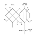
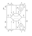
- FIG. 1 is a diagram showing a humidity control element according to the first embodiment of the present invention, (a) a schematic perspective view of the humidity control element, and (b) a schematic view of a moisture permeable membrane.
- FIG. 2 is a schematic perspective view of the air passage unit.
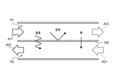
- FIG. 3 is a diagram showing the operating principle of the moisture permeable membrane.
- FIG. 4 is a schematic perspective view showing a humidity control element according to a modified example of the first embodiment.
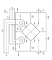
- FIG. 5 is a schematic diagram showing an outline of the humidity control module according to the second embodiment of the present invention.
- FIG. 6 is a schematic view of the humidity control module of the second embodiment.
- 7 is a diagram showing the heat exchange element shown in FIG.
- FIG. 8 is a schematic view of a humidity control module according to a third embodiment of the present invention.
- 9 is a view showing the humidity control element shown in FIG. 8, (a) a schematic perspective view, and (b) a schematic perspective view of the air passage unit.
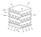
- FIG. 10 is a schematic perspective view showing a humidity control element according to a modified example of the third embodiment.
- FIG. 11 is a schematic view of a humidity control module according to a fourth embodiment of the present invention.
- FIG. 12 is a perspective view of a humidity control module according to a modified example of the fourth embodiment of the present invention.
- FIG. 13 is a schematic view of a humidity control module according to a fifth embodiment of the present invention.
- FIG. 14 is a schematic view of a humidity control module according to a sixth embodiment of the present invention.
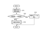
- FIG. 15 is a flowchart showing an operation example of the humidity control system according to the seventh embodiment of the present invention.
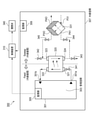
- FIG. 16 is a schematic view of a humidity control system according to an eighth embodiment of the present invention.
- FIG. 17 is a flowchart showing an operation example of the humidity control system shown in FIG.
- FIG. 18 is a flowchart showing an operation example of the humidity control system shown in FIG.
- FIG. 19 is a schematic view showing a humidity control element according to a modified example.
- FIG. 20 is a schematic view of a humidity control module with the humidity control element shown in FIG.
- the inside of the plant factory is controlled to maintain a constant environment suitable for growing plants.
- the temperature is 25 ° C ⁇ 1 ° C
- the relative humidity is 70 ⁇ 10%
- the CO 2 concentration is 1000ppm
- the light intensity is 200 ⁇ mol ⁇ m in units of PPF (Photosynthetic Photon Flux).
- -2 ⁇ s -1 is considered to be a suitable environmental condition (Source: “Handbook of Facility Gardening and Plant Factory” Japan Facility Gardening Association, P333), and it is necessary to keep it within these ranges.
- This disclosure shows an example in which humidity control in a plant factory is performed using a moisture permeable membrane.
- FIG. 1A and 1B are views showing a humidity control element 10 according to the first embodiment of the present invention
- FIG. 1A is a schematic perspective view of the humidity control element 10
- FIG. 1B is a schematic view of a moisture permeable membrane 100.
- FIG. 2 is a schematic perspective view of the air passage units 11 and 12
- FIG. 3 is a diagram showing the operating principle of the moisture permeable membrane 100.
- the humidity control element 10 is formed by alternately stacking air passage units 11 and 12, and includes a first air passage P1, a second air passage P2, a moisture permeable membrane 100, and the like.
- the first air passage P1 passes indoor air, which is the air inside the plant factory (building).
- the second air passage P2 allows outdoor air (outside air), which is the air outside the plant factory, to pass through.
- the moisture permeable membrane 100 may have at least moisture permeability, gas barrier property and thermal conductivity, and its material and composition are not particularly limited.
- the moisture permeable film 100 includes, for example, a porous base paper (Japanese paper, kraft paper, etc.) mainly composed of cellulose fibers in which a moisture absorbing material such as calcium chloride (CaCl 2 ) is dispersed (kneaded), or cellophane.
- a fiber layer containing water-insoluble fibers such as chitin and fibroin in which a hydrophilic material such as aggregated polyethylene glycol and polyvinyl alcohol is dispersed can be used.
- the moisture permeable membrane 100 includes a support 120 and a composite material 110.
- the support 120 contains a porous material such as a polymer or hollow fiber.
- the composite material 110 may be applied onto the support 120.
- the composite material 110 contains a graphene oxide compound and polyvinyl alcohol.
- the graphene oxide compound and polyvinyl alcohol may be crosslinked.
- the graphene oxide compound may be present in an amount of about 0.1% by weight to about 10% by weight based on the weight of polyvinyl alcohol.
- the graphene oxide compound may be graphene oxide, reduced graphene oxide, functionalized graphene oxide, or functionalized and reduced graphene oxide.
- the air passage unit 11 has a moisture permeable membrane 100 having a hexagonal shape in a plan view, and ribs 11a1 to 11a5 erected on the surface of the moisture permeable membrane 100.
- the rib 11a1 has a linear shape along one side of the hexagonal shape.
- the ribs 11a2 to 11a5 each have a straight portion having the same shape as the rib 11a1 and an extending portion extending from both ends of the straight portion.
- the ribs 11a5 are provided along the edge of the moisture permeable membrane 100, and the ribs 11a4 to 11a1 are arranged at equal intervals so that the straight portions are parallel to each other.
- the air passage unit 12 has a moisture permeable membrane 100 having a hexagonal shape in a plan view, and ribs 12a1 to 12a5 erected on the surface of the moisture permeable membrane 100.
- the rib 12a1 has a linear shape along one side of the hexagonal shape.
- the ribs 12a2 to 12a5 each have a straight portion having the same shape as the rib 12a1 and an extending portion extending from both ends of the straight portion.
- the ribs 12a5 are provided along the edge of the moisture permeable membrane 100, and the ribs 12a1 to 12a4 are arranged at equal intervals so that the straight portions are parallel to each other.
- the ribs 11a1 to 11a5 and the ribs 12a1 to 12a5 resins such as polyethylene and polypropylene, metals such as aluminum, glass, ceramics, fiber materials, wood, paper materials and the like can be used. In particular, if a material having good hygroscopicity is used, the moisture permeability performance (latent heat exchange efficiency) of the humidity control element is improved.
- the air passage units 11 and 12 are laminated so that the straight portions of the ribs 11a1 to 11a5 and the ribs 12a1 to 12a5 are parallel to each other.
- the ribs 11a1 to 11a5 and the moisture permeable membranes 100 arranged above and below the ribs 11a1 to 11a5 form the first air passage P1 and form the ribs 12a1 to 12a5.
- the moisture permeable membranes 100 arranged above and below the ribs 12a1 to 12a5 form the second air passage P2.
- a moisture permeable membrane 100 is fixed above the air passage unit 12 in the uppermost layer.
- the inlet P1I and the outlet P1O of the first air passage P1 lead to the inside of the plant factory, and the inlet P2I and the exit P2O of the second air passage P2 lead to the outside of the plant factory (see FIG. 4).
- the inlet P1I and the outlet P1O of the first air passage P1 connect the moisture permeable membrane 100 to two vertices facing each other across the hexagonal outer center of the moisture permeable membrane 100 (in the left-right direction in FIG. 1 (b)). It is arranged on one side of one of the regions divided into two by the extending straight line L). Further, the inlet P2I and the outlet P2O of the second air passage P2 are arranged on the other side of the other region.
- the inlet P1I and the outlet P1O of the first air passage P1 are arranged in one region, and the inlet P2I and the outlet P2O of the second air passage P2 are arranged in the other region across the straight line L, whereby the plant is arranged.
- the number of laminated air passage units 11 and 12 in the humidity control element 10, and the height, width (interval between adjacent ribs) and number of the ribs 11a1 to 11a5 and the ribs 12a1 to 12a5 are appropriately determined according to the specifications. It is set and is not limited to that shown in FIGS. 1 (a) and 2.
- the moisture permeable membrane 100 has a gas barrier property and separates the first air passage P1 and the second air passage P2.
- the moisture permeable film 100 has moisture permeability, and includes indoor air passing through the first air passage P1 (air in the first air passage) and outdoor air passing through the second air passage P2 (air in the second air passage). Water vapor is permeated between them using the water vapor concentration gradient.
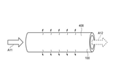
- the indoor air A11 flowing into the first air passage P1 has a higher water vapor concentration than the outdoor air A21 flowing into the second air passage P2
- the water vapor (humidity) contained in the indoor air A11 permeates the moisture permeable membrane 100. And move to the outdoor air A21.
- the outdoor air A22 in which the amount of water vapor contained increases as it passes through the second air passage P2 is discharged to the outside from the second air passage P2.
- the indoor air A12 in which the amount of water vapor contained decreases as it passes through the first air passage P1 is supplied from the first air passage P1 into the plant factory.
- the moisture permeable membrane 100 has thermal conductivity, and the heat of the indoor air passing through the first air passage P1 is transferred to the outdoor air passing through the second air passage P2. As described above, the moisture permeable membrane 100 performs sensible heat exchange and latent heat exchange between the indoor air and the outdoor air.
- the sensible heat exchange efficiency and the latent heat exchange efficiency of the moisture permeable membrane 100 are affected by the thickness (thinner is better), and the temperature difference and humidity difference through the membrane (the larger the difference, the higher the efficiency). Further, the sensible heat exchange efficiency of the moisture permeable film 100 is affected by the thermal conductivity of the material, and the latent heat exchange efficiency of the moisture permeable film 100 is also affected by the moisture permeability (water vapor permeability) and water absorption of the material. The material and thickness of the moisture permeable membrane 100 are determined in consideration of these influences.
- the indoor air A11 passes through the first air passage P1 and returns to the inside of the plant factory as the indoor air A12, and the outdoor air A21 passes through the second air passage P2 and goes out of the building as the outdoor air A22. It is discharged.
- the indoor air A11 and the outdoor air A21 come into contact with each other via the moisture permeable film 100, the water vapor (humidity) and heat are transferred from the indoor air A11 having a high water vapor concentration and temperature to the outdoor air A21 having a low water vapor concentration and temperature. Moves.
- the moisture contained in the indoor air A11 can be released to the outside of the plant factory.
- dehumidification can be performed without using a dehumidifier, so that the energy cost for humidity adjustment can be reduced.
- the humidity control element 10 the humidity can be adjusted without ventilation, so that the adjusted internal environment can be maintained. Therefore, it is suitable for humidity control in a plant factory where it is necessary to maintain high humidity and high CO 2 concentration.
- the number of layers of the air passage units 11 and 12 is appropriately set according to the specifications of the humidity control element 10, such as 200 stages, but by increasing the number of layers, the moisture permeable membrane 100 and the indoor air and outdoor air can be laminated.
- the contact area can be increased to improve the amount of dehumidification.
- by arranging the inlet P1I and the outlet P1O of the first air passage P1 in one region and the inlet P2I and the outlet P2O of the second air passage P2 in the other region the inside and the outside of the plant factory are respectively arranged.
- the ventilation path (piping) configuration can be simplified.
- the ribs 11a1 to 11a5 and the ribs 12a1 to 12a5 each have a straight line portion parallel to each other, the indoor air and the outdoor air passing through the straight line portion (parallel portion) come into contact with each other via the moisture permeable membrane 100. Since the time required for dehumidification becomes longer, the amount of dehumidification can be improved.
- the above-mentioned humidity control element 10 has ribs 11a1 to 11a5 and ribs 12a1 to 12a5 erected on the surface of the moisture permeable membrane 100, but instead of the ribs, a wave shape (wave shape) between adjacent moisture permeable membranes 100.
- a corrugated spacer may be provided.
- the spacer SP1 and the moisture permeable membranes 100 arranged above and below the spacer SP1 form the first air passage P1
- the spacer SP2 and the spacer SP2 are arranged above and below.
- the moisture permeable membrane 100 constitutes the second air passage P2.
- the inlet P1I and the outlet P1O of the first air passage P1 lead to the inside of the plant factory, and the inlet P2I and the outlet P2O of the second air passage P2 lead to the outside of the plant factory.
- the inlet P1I and the outlet P1O of the first air passage P1 connect the moisture permeable membrane 100 to two vertices facing each other across the hexagonal outer center of the moisture permeable membrane 100 (a straight line L extending in the left-right direction in FIG. 4). ) Is divided into two, and it is placed on one side of one area. Further, the inlet P2I and the outlet P2O of the second air passage P2 are arranged on the other side of the other region.
- the inlet P1I and the outlet P1O of the first air passage P1 are arranged in one region, and the inlet P2I and the outlet P2O of the second air passage P2 are arranged in the other region across the straight line L, whereby the plant is arranged.
- the number of layers of the moisture permeable membrane 100 and the spacers SP1 and SP2 in the humidity control element 10B, and the height, width (interval between adjacent waves) and number of waves in the spacers SP1 and SP2 are appropriately set according to the specifications. It is not limited to the one shown in FIG.
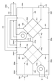
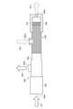
- FIG. 5 is a schematic view showing an outline of the humidity control module 200 according to the second embodiment of the present invention
- FIG. 6 is a schematic vertical sectional view of the humidity control module 200 according to the second embodiment
- 7A and 7B are views showing the heat exchange element 30 shown in FIG. 6,
- FIG. 7A is a schematic perspective view of the heat exchange element 30,
- FIG. 7B is a schematic perspective view of the air passage units 31 and 32.
- solid arrows indicate indoor air flow and dashed arrows indicate outdoor air flow.
- the same or equivalent members / parts as those shown in FIGS. 1 to 4 may be designated by the same reference numerals, and duplicate description may be omitted.
- the outline of the humidity control module 200 will be described with reference to FIG.
- the humidity control element 10 and the heat exchange element 30 are arranged adjacent to each other so as to be in contact with each other.
- the heat exchange element 30 is an element that mainly performs sensible heat exchange, and is a heat exchange element having a latent heat exchange efficiency lower than that of the humidity control element 10.
- the air passage through which the outdoor air supplied from the outside passes and the air passage through which the outdoor air discharged to the outside passes are substantially orthogonal to each other in a plan view, and the moisture permeable film 100A (see FIG. 7). ), Sensible heat exchange (only heat exchange) is performed between the outdoor air passing through each air passage.
- the internal air supplied to the humidity control module 200 from the inside of the plant factory is the outdoor air passing through the second air passage P2 while passing through the humidity control element 10 (first air passage P1).
- the outdoor air supplied to the humidity control module 200 from the outside passes through the heat exchange element 30 as shown by the arrow Y2 and then passes through the humidity control element 10 (second air passage P2) as shown by the arrow Y3. do.
- the outdoor air that has passed through the humidity control element 10 passes through the heat exchange element 30 and is discharged to the outside.
- excess humidity in the plant factory can be released to the outside without ventilation.
- the outdoor air is directly supplied to the humidity control element 10 (second air passage P2) without passing through the heat exchange element 30.
- the humidity control element 10 the temperature of the moisture permeable membrane 100 of the humidity control element 10 drops. Dew condensation occurs when the moisture permeable membrane 100 cools to the dew point or less of the indoor air.
- the moisture permeable film 100 has high latent heat exchange efficiency, when outdoor air having a low temperature is directly supplied to the humidity control element 10, the heat inside the plant factory is transferred to the outdoor air through the moisture permeable film 100. Therefore, a loss of heat energy occurs.
- the outdoor air (see arrow Y3) obtained from the indoor air (see arrow Y1) in the humidity control element 10 is the heat exchange element 30. (See arrow Y4). Therefore, the heat (sensible heat) of the outdoor air (see arrow Y4) is transferred to the outdoor air (see arrow Y2) flowing in from the outside through the moisture permeable film 100A of the heat exchange element 30. In this way, the warmed outdoor air is supplied to the humidity control element 10 (second air passage P2) (see arrow Y3).
- the humidity control module 200 even when the temperature of the outdoor air is low, it is possible to prevent the temperature drop of the moisture permeable membrane 100 and prevent dew condensation on the surface of the moisture permeable membrane 100. Further, according to the humidity control module 200, the difference in heat energy between the indoor air and the outdoor air that come into contact with each other through the moisture permeable film 100 is reduced, so that the heat energy loss from the inside of the plant factory can be reduced. ..
- the humidity control module 200 includes a humidity control element 10, a heat exchange element 30, a case 201, and fans 212 and 213.
- Case 201 accommodates the humidity control element 10 and the heat exchange element 30.
- the case 201 is provided with partition walls 202 to 207 inside, and the humidity control element 10 and the heat exchange element 30 are fixed adjacent to each other so as to be in contact with each other in the center.
- the partition walls 202 and 205 extend in the horizontal direction and vertically partition the internal space of the case 201.
- the partition walls 203 and 204 extend in the vertical direction and horizontally partition the upper side of the internal space of the case 201.
- the partition walls 206 and 207 extend in the vertical direction and horizontally partition the lower side of the internal space of the case 201.
- the heat exchange element 30 is connected to the partition walls 202, 203, 206, and the humidity control element 10 is connected to the partition walls 204, 205, 207.
- the internal space of the case 201 is divided into three spaces, the first space 200a, the second space 200b, and the third space 200c, on the upper side, and the third space 200d, the fifth space 200e, and the sixth space 200f on the lower side. It is divided into two.
- Connection ports 208 to 211 are provided outside the case 201.
- the connection ports 208 and 210 are attached to the openings (not shown) on the left side wall of the case 201, respectively.
- Outdoor air is supplied to the first space 200a through the connection port 208.
- the outdoor air that has passed through the heat exchange element 30 is discharged to the outside from the fourth space 200d through the connection port 210.
- the connection ports 209 and 211 are attached to the openings (not shown) on the right side wall, respectively.
- the indoor air that has passed through the humidity control element 10 is supplied from the third space 200c into the plant factory through the connection port 209. Indoor air is supplied to the sixth space 200f through the connection port 211.
- the fan 212 is arranged in the connection port 209 on the right side wall of the case 201 in the third space 200c, and supplies indoor air to the first air passage P1 of the humidity control element 10 or indoor air from the first air passage P1. Promote emissions.
- the fan 213 is arranged in the connection port 210 on the left side wall of the case 201 in the fourth space 200d, and supplies outdoor air to the second air passage P2 of the humidity control element 10 or the second through the heat exchange element 30. Promotes the discharge of outdoor air from the air passage P2.
- the operation of the fans 212 and 213 is controlled by a control unit (not shown).
- the heat exchange element 30 is formed by alternately stacking air passage units 31 and 32, and has a third air passage P3, a fourth air passage P4, and a moisture permeable membrane 100A. Be prepared.
- the third air passage P3 passes outdoor air supplied from outside the plant factory and supplied to the second air passage P2.
- the fourth air passage P4 passes through the second air passage P2 and allows outdoor air discharged outside the plant factory to pass through.
- the moisture permeable membrane 100A separates the third air passage P3 and the fourth air passage P4, and exchanges heat between the outdoor air passing through the third air passage P3 and the outdoor air passing through the fourth air passage P4. (Mainly sensible heat exchange).
- the moisture permeable membrane 100A may be configured in the same manner as the moisture permeable membrane 100.
- the heat exchange efficiency of the moisture permeable membrane 100A affects not only the thermal conductivity of the material, but also the thickness (the thinner the better), the temperature difference and the humidity difference through the membrane (the larger the difference, the higher the efficiency). receive.
- the material and thickness of the moisture permeable membrane 100A are determined in consideration of these influences.
- the air passage unit 31 has a moisture-permeable membrane 100A having a square shape in a plan view, and a plurality of ribs 31a erected on the surface of the moisture-permeable membrane 100A.
- the rib 31a has a linear shape along one side of a square shape.
- the plurality of ribs 31a are arranged at equal intervals between both edges and the edges of the moisture permeable membrane 100A so as to be parallel to each other.
- the air passage unit 32 has a moisture permeable membrane 100A having a square shape in a plan view, and a plurality of ribs 32a erected on the surface of the moisture permeable membrane 100A.
- the rib 32a has a linear shape along one side of a square shape.
- the plurality of ribs 32a are arranged at equal intervals between both edges and the edges of the moisture permeable membrane 100A so as to be parallel to each other.
- the air passage units 31 and 32 are laminated so that the plurality of ribs 31a and the plurality of ribs 32a are orthogonal to each other.
- the plurality of ribs 31a and the moisture permeable membranes 100A arranged above and below the plurality of ribs 31a form the third air passage P3, and the plurality of ribs 32a and the plurality of ribs 32a.
- the moisture permeable membrane 100A arranged above and below the plurality of ribs 32a constitutes the fourth air passage P4.
- a moisture permeable membrane 100A is fixed above the air passage unit 31 in the uppermost layer.
- the number of laminated air passage units 31 and 32 in the heat exchange element 30, and the height, width (interval between adjacent ribs) and number of the plurality of ribs 31a and 32a are appropriately set according to the specifications. It is not limited to the one shown in FIG. 7.
- a corrugated spacer (see FIGS. 4 and 10) may be provided between the adjacent moisture permeable membranes 100A.
- the inlet P3I of the third air passage P3 leads to the outside of the plant factory, and the outlet P3O of the third air passage P3 is the inlet P2I of the second air passage P2 of the humidity control element 10. Lead to.
- the inlet P4I of the fourth air passage P4 leads to the outlet P2O of the second air passage P2 of the humidity control element 10, and the outlet P4O of the fourth air passage P4 leads to the outside of the plant factory.
- the operation of the humidity control module 200 will be described with reference to FIG.
- Fans 212 and 213 are driven by the control unit.
- indoor air is taken into the sixth space 200f in the case 201 from the inside of the plant factory through the connection port 211.
- the taken-in indoor air is supplied from the inlet P1I to the first air passage P1 of the humidity control element 10.
- the indoor air passing through the first air passage P1 is totally heat exchanged (sensible heat exchange / latent heat exchange) with the outdoor air passing through the second air passage P2 via the moisture permeable film 100, and is third from the outlet P1O. It reaches the space 200c and is returned to the inside of the plant factory via the fan 212 and the connection port 209.
- the outdoor air outside the plant factory is taken into the first space 200a in the case 201 via the connection port 208.
- the taken-in outdoor air is supplied from the inlet P3I to the third air passage P3 of the heat exchange element 30.
- the outdoor air passing through the third air passage P3 is sensible heat exchanged with the outdoor air passing through the fourth air passage P4 via the moisture permeable membrane 100A, from the outlet P3O to the fifth space 200e, and from the inlet P2I. It is supplied to the second air passage P2 of the humidity control element 10.
- the outdoor air passing through the second air passage P2 is totally heat exchanged with the indoor air passing through the first air passage P1 via the moisture permeable membrane 100, and reaches the second space 200b from the outlet P2O.
- the water vapor from the indoor air and the outdoor air containing heat are supplied from the inlet P4I to the fourth air passage P4 of the heat exchange element 30.
- the outdoor air passing through the fourth air passage P4 is sensible heat exchanged with the outdoor air passing through the third air passage P3 via the moisture permeable film 100A, and reaches the fourth space 200d from the outlet P4O, and reaches the fan 213 and the fan 213. It is discharged to the outside of the plant factory via the connection port 210.
- the effect of the humidity control element 10 of the first embodiment can be obtained by a simplified module configuration without using a duct. Further, according to the humidity control module 200, by supplying outdoor air to the humidity control element 10 via the heat exchange element 30, the temperature of the moisture permeable membrane 100 can be lowered even when the temperature of the outdoor air is low. It can be prevented and dew condensation on the surface of the moisture permeable membrane 100 can be prevented. Further, according to the humidity control module 200, the difference in heat energy between the indoor air and the outdoor air that come into contact with each other through the moisture permeable film 100 is reduced, so that the heat energy loss from the inside of the plant factory can be reduced. ..
- FIG. 8 is a schematic view of the humidity control module 200A according to the third embodiment of the present invention.
- 9A and 9B are views showing the humidity control element 10A shown in FIG. 8
- FIG. 9A is a schematic perspective view
- FIG. 9B is a schematic perspective view of the air passage units 11A and 12A.
- solid arrows indicate indoor air flow
- dashed arrows indicate outdoor air flow.
- the same or equivalent members / parts as those shown in FIGS. 1 to 7 may be designated by the same reference numerals, and duplicate description may be omitted.
- the humidity control module 200A includes a humidity control element 10A, a heat exchange element 30, a case 201A, a fan 212, 213, and a first duct 215 and a second duct 216.
- Case 201A accommodates the humidity control element 10A and the heat exchange element 30.
- the case 201A is provided with partition walls 202 to 207, 214a, 214b inside, and the humidity control element 10A and the heat exchange element 30 are fixed adjacent to each other so as to be separated from each other in the center.
- the partition walls 202, 214a, and 205 extend in the horizontal direction and vertically partition the internal space of the case 201A.
- the partition walls 203, 214b, and 204 extend in the vertical direction and horizontally partition the upper side of the internal space of the case 201A.
- the partition walls 206 and 207 extend in the vertical direction and horizontally partition the lower side of the internal space of the case 201A.
- the heat exchange element 30 is connected to the partition walls 202, 203, 214a, 206, and the humidity control element 10A is connected to the partition walls 214a, 204, 205, 207.
- the internal space of the case 201A is divided into four, the first space 200a, the second small space 200b1, 200b2, and the third space 200c on the upper side, and the fourth space 200d, the fifth space 200e, and the sixth space on the lower side. It is divided into three parts of 200f.
- Connection ports 208, 210, 211 are provided outside the case 201A.
- the connection ports 208 and 210 are attached to the openings (not shown) on the left side wall of the case 201A, respectively.
- Outdoor air is supplied to the first space 200a through the connection port 208.
- the outdoor air that has passed through the heat exchange element 30 is discharged to the outside from the fourth space 200d through the connection port 210.
- the connection port 211 is attached to an opening (not shown) on the right side wall.
- the indoor air in the plant factory is supplied to the sixth space 200f through the connection port 211.
- the fan 212 is arranged in the opening (not shown) of the upper wall of the case 201A in the second small space 200b2, and supplies indoor air to the first air passage P1 of the humidity control element 10A or the first air passage P1. Promotes the exhaust of indoor air from.
- the fan 213 is arranged in the connection port 210 on the left side wall of the case 201A in the fourth space 200d, and supplies outdoor air to the second air passage P2 of the humidity control element 10A or the second through the heat exchange element 30. Promotes the discharge of outdoor air from the air passage P2.
- the operation of the fans 212 and 213 is controlled by a control unit (not shown).
- the first duct 215 and the second duct 216 are provided outside the case 201A. Both ends of the first duct 215 are attached to two openings (not shown) on the upper wall of the case 201A, and the third space 200c and the second small space 200b1 communicate with each other. One end of the second duct 216 is attached to an opening in the upper wall of the case 201A where the fan 212 is arranged, and the other end reaches the inside of the plant factory.
- the humidity control element 10A is formed by alternately stacking air passage units 11A and 12A, and has a first air passage P1, a second air passage P2, and a moisture permeable membrane 100. Be prepared.
- the first air passage P1 passes indoor air, which is the air inside the plant factory (building).
- the second air passage P2 allows outdoor air, which is the air outside the plant factory, to pass through.
- the moisture permeable membrane 100 divides the first air passage P1 and the second air passage P2, and sensible heat is generated between the indoor air passing through the first air passage P1 and the outdoor air passing through the second air passage P2. Exchange and latent heat exchange.
- the air passage unit 11A has a moisture permeable membrane 100 having a square shape in a plan view, and a plurality of ribs 11Aa erected on the surface of the moisture permeable membrane 100.
- the rib 11Aa has a linear shape along one side of a square shape.
- the plurality of ribs 11Aa are arranged at equal intervals between both edges and the edges of the moisture permeable membrane 100 so as to be parallel to each other.
- the air passage unit 12A has a moisture permeable membrane 100 having a square shape in a plan view, and a plurality of ribs 12Aa erected on the surface of the moisture permeable membrane 100.
- the rib 12Aa has a linear shape along one side of a square shape.
- the plurality of ribs 12Aa are arranged at equal intervals between both edges and the edges of the moisture permeable membrane 100 so as to be parallel to each other.
- the air passage units 11A and 12A are laminated so that the plurality of ribs 11Aa and the plurality of ribs 12Aa are orthogonal to each other.
- the plurality of ribs 11Aa and the moisture permeable membranes 100 arranged above and below the plurality of ribs 11Aa form the first air passage P1, and the plurality of ribs 12Aa and the plurality of ribs 12Aa.
- the moisture permeable membrane 100 arranged above and below the plurality of ribs 12Aa constitutes the second air passage P2.
- a moisture permeable membrane 100 is fixed above the air passage unit 11A in the uppermost layer.
- the inlet P1I and the outlet P1O of the first air passage lead to the inside of the plant factory, and the inlet P2I and the exit P2O of the second air passage P2 lead to the outside of the plant factory (see FIG. 8).
- the inlet P1I and the outlet P1O of the first air passage P1 are provided on two opposite sides of the square moisture permeable membrane 100, respectively.
- the inlet P2I and the outlet P2O of the second air passage P2 are provided on two opposite sides of the square moisture permeable membrane 100, which are different from the two sides.
- the number of laminated air passage units 11A and 12A in the humidity control element 10A, and the size, width (interval between adjacent ribs) and number of the plurality of ribs 11Aa and 12Aa are appropriately set according to the specifications.
- the present invention is not limited to that shown in FIG.
- the operation of the humidity control module 200A will be described with reference to FIG.
- Fans 212 and 213 are driven by the control unit.
- indoor air is taken into the sixth space 200f in the case 201A from the inside of the plant factory through the connection port 211.
- the taken-in indoor air is supplied from the inlet P1I to the first air passage P1 of the humidity control element 10A.
- the indoor air passing through the first air passage P1 is totally heat exchanged (sensible heat exchange / latent heat exchange) with the outdoor air passing through the second air passage P2 via the moisture permeable film 100, and is second from the outlet P1O. It reaches the small space 200b2 and is returned to the inside of the plant factory through the second duct 216 via the fan 212 and the opening.
- the outdoor air outside the plant factory is taken into the first space 200a in the case 201A via the connection port 208.
- the taken-in outdoor air is supplied from the inlet P3I to the third air passage P3 of the heat exchange element 30.
- the outdoor air passing through the third air passage P3 is sensible heat exchanged with the outdoor air passing through the fourth air passage P4 via the moisture permeable membrane 100A, from the outlet P3O to the fifth space 200e, and from the inlet P2I. It is supplied to the second air passage P2 of the humidity control element 10A.
- the outdoor air passing through the second air passage P2 is totally heat exchanged with the indoor air passing through the first air passage P1 via the moisture permeable membrane 100, and reaches the third space 200c from the outlet P2O.
- the water vapor and the outdoor air containing heat from the indoor air pass through the first duct 215 through the opening of the upper wall of the case 201A, reach the second small space 200b1, and reach the second small space 200b1 from the inlet P4I to the fourth heat exchange element 30. It is supplied to the air passage P4.
- the outdoor air passing through the fourth air passage P4 is sensible heat exchanged with the outdoor air passing through the third air passage P3 via the moisture permeable film 100A, and reaches the fourth space 200d from the outlet P4O, and reaches the fan 213 and the fan 213. It is discharged to the outside of the plant factory via the connection port 210.
- the same effect as that of the second embodiment can be realized by a configuration different from that of the humidity control module 200 of the second embodiment.
- the orthogonal type humidity control element 10A and the first duct 215 and the second duct 216 are combined to form an air passage for circulating indoor air and outdoor air. Therefore, although the module configuration is more complicated than the humidity control module 200 of the second embodiment using the countercurrent type humidity control element 10, in the third embodiment, the orthogonal type humidity control element 10A is used. , Can construct an air passage that circulates indoor air and outdoor air.
- the above-mentioned humidity control element 10A has a plurality of ribs 11Aa and ribs 12Aa erected on the surface of the moisture permeable membrane 100, but instead of the ribs, a wave shape (corrugate) is formed between the adjacent moisture permeable membranes 100. Spacer may be provided.
- the spacer SPC1 and the moisture permeable membranes 100 arranged above and below the spacer SPC1 form the first air passage P1
- the spacer SPC2 and the spacer SPC2 are arranged above and below.
- the moisture permeable membrane 100 constitutes the second air passage P2.
- the inlet P1I and the outlet P1O of the first air passage P1 lead to the inside of the plant factory, and the inlet P2I and the outlet P2O of the second air passage P2 lead to the outside of the plant factory.
- the inlet P1I and the outlet P1O of the first air passage P1 are provided on two opposite sides of the square moisture permeable membrane 100, respectively.
- the inlet P2I and the outlet P2O of the second air passage P2 are provided on two opposite sides of the square moisture permeable membrane 100, which are different from the two sides.
- the number of layers of the moisture permeable membrane 100 and the spacers SPC1 and SPC2 in the humidity control element 10C, and the height, width (interval between adjacent waves) and number of waves in the spacers SPC1 and SPC2 are appropriately set according to the specifications. It is not limited to the one shown in FIG.
- FIG. 11 is a schematic view of the humidity control module 200B according to the fourth embodiment of the present invention.
- FIG. 12 is a perspective view of the inside of the humidity control module 200B-1 according to the modified example of the fourth embodiment of the present invention.
- solid arrows indicate indoor air flow and dashed arrows indicate outdoor air flow.
- the same or equivalent members / parts as those shown in FIGS. 1 to 10 may be designated by the same reference numerals, and duplicate description may be omitted.
- the humidity control module 200B shown in FIG. 11 is different from the humidity control module 200 shown in FIG. 6 in that it does not have the heat exchange element 30 and the arrangement of the fan 212 is mainly different.
- Case 201B is provided with partition walls 202, 204, 205, 207 inside, and the humidity control element 10 is fixed in the center.
- the internal space of the case 201B is divided into two spaces, the first space 200a and the third space 200c, on the upper side, and the fourth space 200d and the sixth space 200f on the lower side.
- Connection ports 208 to 211 are provided outside the case 201B.
- the connection ports 208 and 210 are attached to the openings (not shown) on the left side wall of the case 201B, respectively.
- Outdoor air is supplied to the first space 200a through the connection port 208.
- the outdoor air that has passed through the humidity control element 10 is discharged to the outside from the fourth space 200d through the connection port 210.
- the indoor air in the plant factory is supplied to the third space 200c through the connection port 209.
- the indoor air that has passed through the humidity control element 10 is returned to the inside of the plant factory from the sixth space 200f via the connection port 211.
- the fan 212 is arranged in the connection port 211 on the right side wall of the case 201B in the sixth space 200f, and supplies indoor air to the first air passage P1 of the humidity control element 10 or indoor air from the first air passage P1. Promote emissions.
- the fan 213 is arranged in the connection port 210 on the left side wall of the case 201B in the fourth space 200d, and supplies outdoor air to the second air passage P2 of the humidity control element 10 or outdoor air from the second air passage P2. Promote emissions.
- the operation of the fans 212 and 213 is controlled by a control unit (not shown).
- the operation of the humidity control module 200B will be explained.
- Fans 212 and 213 are driven by the control unit.
- indoor air is taken into the third space 200c in the case 201B from the inside of the plant factory through the connection port 209.
- the taken-in indoor air is supplied from the inlet P1I to the first air passage P1 of the humidity control element 10.
- the indoor air passing through the first air passage P1 is totally heat exchanged (sensible heat exchange / latent heat exchange) with the outdoor air passing through the second air passage P2 via the moisture permeable film 100, and the sixth from the outlet P1O. It reaches the space 200f and is returned to the inside of the plant factory through the fan 212 and the opening.
- the outdoor air outside the plant factory is taken into the first space 200a in the case 201B via the connection port 208.
- the taken-in outdoor air is supplied from the inlet P2I to the second air passage P2 of the humidity control element 10.
- the outdoor air passing through the second air passage P2 is totally heat exchanged with the indoor air passing through the first air passage P1 via the moisture permeable membrane 100, and reaches the fourth space 200d from the outlet P2O.
- the outdoor air containing water vapor and heat from the indoor air is discharged to the outside of the plant factory via the fan 213 and the connection port 210.
- the humidity control module 200B-1 shown in FIG. 12 does not have partition walls 204 and 207 inside the case 201B, and the arrangement of the fans 212 and 213 is the main. Different to.
- the case 201B has a rectangular parallelepiped shape and has an upper wall 201B1, a lower wall 201B2, a left side wall 201B3, a right side wall 201B4, a front wall 201B5, and a rear wall 201B6.
- the case 201B is provided with partition walls 202 and 205 extending horizontally from the left and right side walls 201B3 and 201B4, respectively.
- a humidity control element 10 extending from the front wall 201B5 to the rear wall 201B6 is fixed.
- the humidity control element 10 is sandwiched between the upper wall 201B1 and the lower wall 201B2 at the top and bottom, and is sandwiched between the partition walls 202 and 205 on the left and right, and is fixed in the case 201B.
- the internal space of the case 201B is divided into two spaces, the first space 200a and the third space 200c, by the partition walls 202 and 205 and the humidity control element 10, and the lower side is the fourth space 200d and the sixth space 200f. It is divided into two parts.
- a standing wall 219 connecting the lower wall 201B2 and the partition wall 205 and a standing wall 220 extending from the standing wall 219 to the front wall 201B5 are provided.
- a vertical wall 221 that connects the upper wall 201B1 and the partition wall 205 and extends from the front wall 201B5 to a substantially central position in the front-rear direction is provided along the right side wall 201B4.
- a standing wall 222 connecting the lower wall 201B2 and the partition wall 202 and a standing wall 223 extending from the standing wall 222 to the rear wall 201B6 are provided.
- a vertical wall 224 that connects the upper wall 201B1 and the partition wall 202 and extends from the rear wall 201B6 to a substantially central position in the front-rear direction is provided along the left side wall 201B3.
- the left and right side walls 201B3 and 201B4 of the case 201B are provided with openings K1 to K4.
- the opening K1 is provided behind the lower side of the right side wall 201B4.
- the indoor air in the plant factory is supplied to the sixth space 200f through the opening K1.
- the opening K2 is provided in front of the upper side of the right side wall 201B4.
- Outdoor air is supplied to the fourth space 200d through the opening K3.
- the opening K4 is provided behind the upper side of the left side wall 201B3.
- the outdoor air that has passed through the humidity control element 10 is discharged to the outside from the first space 200a through the opening K4.
- the fan 212 is arranged between the right side wall 201B4 and the vertical wall 221 in the third space 200c, and supplies indoor air to the first air passage P1 of the humidity control element 10 or indoor air from the first air passage P1. Promote the emission of.
- the fan 213 is arranged between the left side wall 201B3 and the vertical wall 224 in the first space 200a, and supplies outdoor air to the second air passage P2 of the humidity control element 10 or outdoor air from the second air passage P2. Promote the emission of.
- the operation of the fans 212 and 213 is controlled by a control unit (not shown).
- the operation of the humidity control module 200B-1 will be explained.
- Fans 212 and 213 are driven by the control unit.
- indoor air is taken into the sixth space 200f in the case 201B from the inside of the plant factory through the opening K1.
- the taken-in indoor air is guided by the standing wall 219 and the standing wall 220 and flows into the first air passage P1 of the humidity control element 10 from the inlet P1I.
- the indoor air passing through the first air passage P1 is totally heat exchanged (sensible heat exchange / latent heat exchange) with the outdoor air passing through the second air passage P2 via the moisture permeable membrane 100, and the third from the outlet P1O. It reaches the space 200c.
- the indoor air supplied to the third space 200c is guided by the standing wall 221 and returned to the inside of the plant factory via the fan 212 and the opening K2.
- the outdoor air outside the plant factory is taken into the fourth space 200d in the case 201B through the opening K3.
- the taken-in outdoor air is guided by the standing wall 222 and the standing wall 223, and is supplied from the inlet P2I to the second air passage P2 of the humidity control element 10.
- the outdoor air passing through the second air passage P2 is totally heat exchanged with the indoor air passing through the first air passage P1 via the moisture permeable membrane 100, and reaches the first space 200a from the outlet P2O.
- the outdoor air supplied to the first space 200a is guided to the vertical wall 224 and discharged to the outside through the fan 213 and the opening K4.
- the same effect as that of the humidity control element 10 of the first embodiment can be realized.
- FIG. 13 is a schematic view of the humidity control module 200C according to the fifth embodiment of the present invention.
- solid arrows indicate indoor air flow and dashed arrows indicate outdoor air flow.
- the same or equivalent members / parts as those shown in FIGS. 1 to 12 may be designated by the same reference numerals, and duplicate description may be omitted.
- the humidity control module 200C does not have the heat exchange element 30, and instead of the first duct 215 and the second duct 216, the third duct 217 and the fourth duct The point that 218 is provided and the arrangement of the fan 213 are mainly different.
- Case 201C is provided with partition walls 202, 204, 205, 207 inside, and the humidity control element 10A is fixed in the center.
- the internal space of the case 201C is divided into two spaces, the first space 200a and the third space 200c, on the upper side, and the fourth space 200d and the sixth space 200f on the lower side.
- Connection ports 210 and 211 are provided outside the case 201C.
- the connection port 210 is attached to an opening (not shown) on the left wall of the case 201C. Outdoor air is supplied to the fourth space 200d through the connection port 210.
- the connection port 211 is attached to an opening (not shown) on the right side wall. The indoor air in the plant factory is supplied to the sixth space 200f through the connection port 211.
- the fan 212 is arranged in the opening (not shown) of the upper wall of the case 201C in the first space 200a, and supplies indoor air to the first air passage P1 of the humidity control element 10A or from the first air passage P1. Promotes the exhaust of indoor air.
- the fan 213 is arranged in the opening of the upper wall of the case 201C in the third space 200c, and supplies outdoor air to the second air passage P2 of the humidity control element 10A or discharges outdoor air from the second air passage P2. To promote.
- the operation of the fans 212 and 213 is controlled by a control unit (not shown).
- the third duct 217 and the fourth duct 218 are provided outside the case 201C.
- One end of the third duct 217 is attached to an opening in the upper wall of the case 201C where the fan 212 is arranged, and the other end reaches the inside of the plant factory.
- One end of the fourth duct 218 is attached to an opening in the upper wall of the case 201C where the fan 213 is arranged, and the other end reaches the outside of the plant factory.
- the operation of the humidity control module 200C will be explained.
- Fans 212 and 213 are driven by the control unit.
- indoor air is taken into the sixth space 200f in the case 201A from the inside of the plant factory through the connection port 211.
- the taken-in indoor air is supplied from the inlet P1I to the first air passage P1 of the humidity control element 10A.
- the indoor air passing through the first air passage P1 is totally heat exchanged (sensible heat exchange / latent heat exchange) with the outdoor air passing through the second air passage P2 via the moisture permeable film 100, and is first from the outlet P1O. It reaches the space 200a and is returned to the inside of the plant factory through the third duct 217 via the fan 212 and the opening.
- the outdoor air outside the plant factory is taken into the fourth space 200d in the case 201C via the connection port 210.
- the taken-in outdoor air is supplied from the inlet P2I to the second air passage P2 of the humidity control element 10A.
- the outdoor air passing through the second air passage P2 is totally heat exchanged with the indoor air passing through the first air passage P1 via the moisture permeable membrane 100, and reaches the third space 200c from the outlet P2O.
- the water vapor and the outdoor air containing heat from the indoor air are discharged to the outside of the plant factory through the fourth duct 218 through the fan 213 and the opening on the upper wall of the case 201C.
- the orthogonal type humidity control element 10A and the third duct 217 and the fourth duct 218 are combined to circulate the indoor air and the outdoor air to circulate the first.
- the same effect as that of the humidity control element 10 of one embodiment can be realized.
- FIG. 14 is a schematic view of the humidity control module 200D according to the sixth embodiment of the present invention.
- solid arrows indicate indoor air flow and dashed arrows indicate outdoor air flow.
- the same or equivalent members / parts as those shown in FIGS. 1 to 13 may be designated by the same reference numerals, and duplicate description may be omitted.
- the humidity control module 200D is provided with a plurality of rows of humidity control elements 10A shown in FIG. 13 in parallel. Compared with the humidity control module 200C, the humidity control module 200D includes a fifth duct 225, a sixth duct 226, a seventh duct 227, and an eighth duct 228 in place of the third duct 217 and the fourth duct 218. And the arrangement of the fans 212 and 213 are mainly different.
- Case 201D is provided with partition walls 202, 205, 229 to 236 inside.
- three humidity control elements 10A are fixed adjacent to each other in the left-right direction.
- the partition walls 230 and 232 extend vertically from the upper wall to the lower wall of the case 201D and horizontally partition the internal space of the case 201D.
- the partition walls 229, 231 and 233 extend vertically from the upper wall of the case 201D to the upper end of the humidity control element 10A, and horizontally partition the upper side of the internal space of the case 201D.
- the partition walls 234, 235, and 236 extend vertically from the lower end of the humidity control element 10A to the lower wall of the case 201D, and horizontally partition the lower side of the internal space of the case 201D.
- the internal space of the case 201D is divided into six, the first space 200a, the second small space 200b1 to 200b4, and the third space 200c on the upper side, and the fourth space 200d, the fifth small space 200e1 to 200e4, and the lower side. It is divided into six parts of the sixth space 200f.
- the fifth duct 225, the sixth duct 226, the seventh duct 227, and the eighth duct 228 each branch in four directions and are provided outside the case 201D.
- the fifth duct 225 on the upper wall of the case 201D, three ends are attached to each of the three openings, and one end reaches the inside of the plant factory.
- the fifth duct 225 communicates the second small spaces 200b1, 200b3 and the third space 200c with the inside of the plant factory.
- the sixth duct 226 has three ends attached to each of the three openings in the lower wall of the case 201D, and one end reaches the inside of the plant factory.
- the sixth duct 226 communicates the fourth space 200d, the fifth small space 200e2, and the fifth small space 200e4 with the inside of the plant factory.
- the seventh duct 227 has three ends attached to each of the three openings in the upper wall of the case 201D, and one end reaches the outside of the plant factory.
- the seventh duct 227 communicates the first space 200a, the second small space 200b2, and the second small space 200b4 with the outside of the plant factory.
- the eighth duct 228 has three ends attached to three openings in the lower wall of the case 201D, and one end thereof leads to the outside of the plant factory.
- the eighth duct 228 communicates the fifth small space 200e1, 200e3 and the sixth space 200f with the outside of the plant factory.
- the fan 212 is arranged at the end of the sixth duct 226 leading to the inside of the plant factory, and supplies indoor air to the first air passage P1 of the humidity control element 10A or discharges indoor air from the first air passage P1.
- the fan 213 is arranged at the end of the eighth duct 228 leading to the outside of the plant factory, and supplies outdoor air to the second air passage P2 of the humidity control element 10A or discharges outdoor air from the second air passage P2.
- the operation of the fans 212 and 213 is controlled by a control unit (not shown).
- the operation of the humidity control module 200D will be explained.
- Fans 212 and 213 are driven by the control unit.
- indoor air is taken into the second small spaces 200b1, 200b3 and the third space 200c in the case 201D from the inside of the plant factory through the fifth duct 225.
- the taken-in indoor air is supplied from the inlet P1I to the first air passage P1 in each humidity control element 10A.
- the indoor air passing through the first air passage P1 is totally heat exchanged (sensible heat exchange / latent heat exchange) with the outdoor air passing through the second air passage P2 via the moisture permeable film 100.
- the indoor air is returned to the inside of the plant factory through the sixth duct 226 and the fan 212.
- the outdoor air outside the plant factory passes through the seventh duct 227 and is taken into the first space 200a, the second small space 200b2 and the second small space 200b4 in the case 201D.
- the taken-in outdoor air is supplied to the second air passage P2 from the inlet P2I in each humidity control element 10A.
- the outdoor air passing through the second air passage P2 is totally heat exchanged with the indoor air passing through the first air passage P1 via the moisture permeable membrane 100, and the fifth small space 200e1, 200e3 and the fifth small space 200e1, 200e3 and the fifth from each outlet P2O.
- Each of the six spaces 200f is reached.
- the outdoor air containing water vapor and heat from the indoor air is discharged to the outside of the plant factory through the eighth duct 228 and the fan 213.
- the humidity control module 200D of the present embodiment by using the orthogonal type humidity control elements 10A having a plurality of rows (three rows in this example), the humidity control module 200C of the fifth embodiment is compared with the humidity control module 200C of the fifth embodiment. Therefore, the humidity of indoor air can be adjusted multiple times (three times in this example).
- FIG. 15 is a flowchart showing an operation example of the humidity control system according to the seventh embodiment of the present invention.
- the humidity control system of the present embodiment is at least one of the humidity control modules 200, 200A, 200B, 200B-1, 200C, and 200D of the second to sixth embodiments (hereinafter, referred to as humidity control module 200 and the like).
- an air conditioner air conditioner that adjusts the temperature of the indoor air inside the plant factory within a predetermined range.
- This humidity control system may include a control device (not shown) and a humidity monitoring unit that monitors the humidity of the indoor air inside the plant factory.
- the control device controls the operation of the humidity control module 200 and the like according to the humidity fluctuation inside the plant factory.
- the control device operates the humidity control module 200 or the like when the fluctuation of humidity satisfies the specified condition.
- the control device has a storage unit and a calculation unit, is connected to a control unit such as a humidity control module 200 and a control unit of an air conditioner, and the calculation unit executes a predetermined program stored in the storage unit.
- the operation shown in 15 is realized.
- the process shown in FIG. 15 is repeatedly executed at predetermined time intervals.
- the control device monitors the humidity inside the plant factory (step S1), and if the humidity fluctuation satisfies the specified condition stored in the storage unit (Yes in step S2), the humidity control module 200 Etc. are operated (step S3).
- the specified condition the relative humidity inside the plant factory is 70% RH or more.
- the control device stops the operation of the humidity control module 200 and the like (step S4), and ends this process.
- a combined air conditioning system in which an air conditioner and a humidity control module 200 or the like are used in combination to share the processing of sensible heat and latent heat to improve the overall energy efficiency.
- the energy cost can be reduced by using the humidity control module 200 or the like as a device in charge of removing latent heat.
- the control device controls the operation of the humidity control module 200, etc. in response to humidity fluctuations, so that the humidity control module 200, etc. is automatically operated when the need for dehumidification is high, and the energy cost related to latent heat removal. Can be reduced.
- FIG. 16 is a schematic view of the humidity control system according to the eighth embodiment of the present invention.
- the humidity control system 300 of the present embodiment includes a facility 301 such as a plant factory having a management space 303 isolated from the external space 307, a humidity control module 320 and a heat exchange element 331 installed in the facility 301, and a control device 310. And prepare.
- the facility 301 and the humidity control module 320, and the humidity control module 320 and the heat exchange element 331 are connected by, for example, piping.
- the "facility" includes equipment such as plant growing equipment installed in the building.
- the external space 307 may be outdoors or may be outside the facility 301 in the building.
- the humidity control module 320 has a first air passage through which the internal air, which is the air inside the control space 303, passes through, a second air passage through which the external air, which is the air outside the facility 301, passes through, and the first air passage and the second air passage. It has a humidity control element having a moisture permeable film that separates the air passage and allows water vapor to pass between the internal air and the external air.
- the humidity control element in the humidity control module 320 the above-mentioned humidity control elements 10, 10A, 10B, 10C, or a general countercurrent element can be used.
- the heat exchange element 331 the heat exchange element 30 described above can be used.
- the humidity control module 320 is provided with connection ports 3211, 322, 323, 324 in a case for accommodating the humidity control element.
- the humidity control module 320 is connected to the discharge port 301a of the facility 301 via the connection port 321 and the on-off valve 341. Further, the humidity control module 320 is connected to the suction port 301b of the facility 301 via the connection port 322.
- the on-off valve 341 When the on-off valve 341 is opened, the internal air is discharged from the control space 303 and supplied to the first air passage of the humidity control module 320.
- the on-off valve 341 is closed, the supply of the internal air to the humidity control module 320 is stopped.
- the humidity control module 320 external air is supplied to the second air passage through the connection port 323 and the on-off valve 342. Further, in the humidity control module 320, the external air that has passed through the second air passage is discharged to the external space 307 via the connection port 324 and the on-off valve 343. By opening the on-off valves 342 and 343, the outside air passes through the second air passage.
- the internal air supplied from the discharge port 301a to the first air passage is supplied from the connection port 323 and passes through the second air passage in the humidity control module 320.
- Total heat exchange sensible heat exchange / latent heat exchange
- the internal air that has undergone total heat exchange is returned from the suction port 301b to the management space 303 in the facility 301.
- the heat exchange element 331 is connected to the outlet P3O of the third air passage and the connection port 323 via the on-off valve 345.
- the on-off valve 345 opens, the external air flowing into the heat exchange element 331 from the inlet P3I of the third air passage passes through the third air passage, and the second wind of the humidity control module 320 passes through the connection port 323. Supplied to the road.
- the heat exchange element 331 is connected to the inlet P4I of the fourth air passage and the connection port 324 via the on-off valve 344.
- the on-off valve 344 By opening the on-off valve 344, the external air that has passed through the second air passage of the humidity control module 320 is discharged from the connection port 324.
- the external air discharged from the connection port 324 flows into the fourth air passage of the heat exchange element 331 from the inlet P4I of the fourth air passage, passes through the fourth air passage, and is outside from the outlet P4O of the fourth air passage. It is discharged to the space 307.
- a monitoring unit 305 that monitors the temperature and humidity of the internal air is provided.
- the external space 307 is provided with a monitoring unit 309 that monitors the temperature and humidity of the external air.
- the control device 310 has a storage unit and a calculation unit, and is connected to monitoring units 305, 309 and on-off valves 341 to 345 (hereinafter, may be collectively referred to as on-off valves 340). As shown in FIGS. 17 and 18, the control device 310 controls the operation of the humidity control module 320 by the arithmetic unit executing a predetermined program stored in the storage unit, and controls the operation of the humidity control module 320 to control the temperature in the control space 303. ⁇ Adjust the humidity. The processes shown in FIGS. 17 and 18 are repeatedly executed at predetermined time intervals.
- control device 310 monitors the humidity inside and outside the facility 301 by the monitoring units 305 and 309 (step S11).
- the control device 310 stops the operation of the humidity control module 302 by at least closing the on-off valve 341 (step S13).
- the absolute humidity inside the control space 303 measured by the monitoring unit 305 is lower than the absolute humidity of the external space 307 measured by the monitoring unit 309, regardless of the internal temperature and the external temperature, the inside of the control space 303 is humidified. It ends up. Therefore, in this case, the humidity control module 320 is stopped to maintain the humidity in the control space 303.
- step S12 when the internal humidity is not lower than the external humidity (NO in step S12), the control device 310 performs air passage switching control described later (step S14).
- FIG. 18 is a flowchart showing a processing procedure of air passage switching control by the control device 310.
- the control device 310 opens the on-off valve 341 to operate the humidity control module 320.
- the control device 310 monitors the temperature inside and outside the facility 301 by the monitoring units 305 and 309 (step S21).
- control device 310 determines whether or not the internal temperature is within a predetermined range in an appropriate temperature range (step S23).
- the control device 310 allows the external air (outside air) that has passed through the heat exchange element 331 to be passed through the connection port 323 to the second air passage of the humidity control module 320. (Step S24). That is, the control device 310 can adjust the humidity while suppressing the temperature change inside the control space 303 by opening the on-off valves 344 and 345 and closing the on-off valves 342 and 343.
- the control device 301 supplies the outside air that does not pass through the heat exchange element 331 to the second air passage of the humidity control module 320 from the connection port 323 ( Step S25). That is, the control device 310 can positively heat the inside of the control space 303 by opening the on-off valves 342 and 343 and closing the on-off valves 344 and 345.
- the control device 301 supplies the outside air that does not pass through the heat exchange element 331 to the second air passage of the humidity control module 320 from the connection port 323 ( Step S28). That is, the control device 310 can positively cool the inside of the control space 303 by opening the on-off valves 342 and 343 and closing the on-off valves 344 and 345.
- control device 310 determines whether or not the internal temperature is within a predetermined range (step S26).
- the control device 310 When the internal temperature is not higher than the external temperature and is within a predetermined range or higher than a predetermined range, the control device 310 sends the external air (outside air) that has passed through the heat exchange element 331 from the connection port 323 to the humidity control module 320. Supply to the second air passage (step S27). That is, the control device 310 can adjust the humidity without changing the inside of the control space 303 by opening the on-off valves 344 and 345 and closing the on-off valves 342 and 343.
- the control device 301 supplies the outside air that does not pass through the heat exchange element 331 to the second air passage of the humidity control module 320 from the connection port 323 ( Step S28). That is, the control device 310 can positively heat the inside of the control space 303 by opening the on-off valves 342 and 343 and closing the on-off valves 344 and 345.
- the air passage switching control is performed in the humidity control system 300 according to the temperature and humidity inside and outside the facility 301.
- the control device 310 may further perform the same control as the process shown in FIG.
- the humidity control element 480 is a hollow fiber membrane, and has a tubular portion in which a flat moisture permeable film 100 is formed in a hollow tubular shape.
- the hollow portion inside the cylinder is the first air passage through which the internal air passes, and the space outside the cylinder, that is, the space in contact with the outer peripheral surface is the second air passage through which the outside air passes. ..
- the humidity control element 408 transmits water vapor using a water vapor concentration gradient between the air A11 (internal air) passing through the inside of the humidity control element 408 and the external air passing through the outer peripheral surface of the humidity control element 408. Let me. When the air A11 has a higher water vapor concentration than the external air, the water vapor contained in the air A11 permeates the moisture permeable membrane 100 and moves to the external air passing through the outer peripheral surface of the humidity control element 408. Further, the humidity control element 408 has thermal conductivity, and the heat of the air A11 is transferred to the outside air via the humidity control element 408.
- the difference in water vapor concentration between the internal air and the external air may be provided by pressurizing the internal air to increase the water vapor concentration or depressurizing the external air to decrease the water vapor concentration.
- the humidity control element 408 As the air A12 passes through the inside of the humidity control element 408, the amount of water vapor contained and the heat are reduced, and the air A12 is supplied to the management space 303 in the facility 301.
- Either the inside or the outside of the humidity control element 480 may be the first air passage or the second air passage.
- FIG. 20 is a schematic view of a membrane dryer 400, which is a humidity control module provided with the humidity control element 408 shown in FIG.
- FIG. 20 is a cross-sectional view of a part of the membrane dryer 400 in a side view.
- the membrane dryer 400 includes a hollow cylindrical case 402 having both ends open, a plurality of humidity control elements 408 arranged in the case 402, and end cases 404 and 406 that cover both ends of the case 402, respectively. ..
- the membrane dryer 400 includes a holding member 410 that closes both ends of the case 402 and holds both ends of the humidity control element 408 in the end cases 404 and 406.
- the holding member 410 closes between the plurality of humidity control elements 408 and the end cases 404, 406.
- the case 402 is provided with two openings 402a and 402b that allow the inside and outside of the case 402 to communicate with each other.
- the end cases 404 and 406 have openings 404a and 406a, respectively.
- the air A11 (internal air) flowing in from the opening 404a passes through the inside of the plurality of humidity control elements 408.
- Air A21 (external air) is supplied from the opening 402a to the outer peripheral surface of the humidity control element 408 in the case 402, and total heat exchange with the air A11 is performed.
- the air A12 having a reduced amount of water vapor and heat is discharged from the opening 406a and returned to the control space 303 in the facility 301.
- the air A22 that has received the transfer of water vapor and heat from the air A11 on the outer peripheral surface of the humidity control element 408 is discharged from the opening 402b to the external space 307 outside the facility 301.
- a plurality of humidity control elements 408 or membrane dryer 400 may be used instead of the above-mentioned humidity control elements 10, 10A, 10B, and 10C.
- the present invention is not limited to the above-described embodiment, and can be appropriately modified, improved, or the like.
- the material, shape, size, numerical value, form, number, arrangement location, etc. of each component in the above-described embodiment are arbitrary as long as the present invention can be achieved, and are not limited.
- the humidity control element 10 has a hexagonal shape in a plan view, but the plane shape is divided into two by a straight line, and the inlet and the outlet of the first air passage are arranged on one surface side of one region.
- the inlet and outlet of the second air passage are arranged on the other surface side of the other region, they may have different shapes such as a square shape in a plan view.
- the humidity control modules 200, 200A, 200B, 200B-1, 200C, 200D include cases 201, 201A, 201B, 201C, 201D (hereinafter referred to as case 201 and the like), but the case. 201 etc. is not essential.
- the humidity control element 10 may be embedded in the wall surface to form a humidity control module.
- a plurality of humidity control elements 10 may be arranged, for example, in the vertical direction without gaps so that the moisture permeable film 100 extends along the thickness direction of the wall to form a humidity control module.
- the heat exchange element 30 may be embedded in the wall surface so as to be adjacent to the humidity control element 10.
- [1] First air passage (P1) and The second air passage (P2) and A moisture permeable membrane (100) that separates the first air passage and the second air passage and allows water vapor to permeate between the air of the first air passage and the air of the second air passage is provided.
- the moisture permeable membrane has a planar shape, the first air passage is provided on one surface, and the second air passage is provided on the other surface.
- the inlet (P1I) and the outlet (P1O) of the first air passage are arranged on the one surface side of one region obtained by dividing the planar shape into two by a straight line, and the first air passage is arranged on the other surface side of the other region.
- the entrance (P2I) and exit (P2O) of the two air passages are arranged.
- the moisture permeable membrane is A plurality of first moisture permeable membranes having a plurality of first ribs (11a1 to 11a5) erected on the surface forming the first air passage, and a plurality of first moisture permeable membranes.
- a plurality of second moisture permeable membranes having a plurality of second ribs (12a1 to 12a5) erected on the surface forming the second air passage are included.
- a humidity control module including the humidity control element according to any one of the above [1] to [3] and a heat exchange element having a latent heat exchange efficiency lower than that of the humidity control element. The heat exchange element is provided adjacent to the humidity control element.
- Humidity control module 200, 200A
- a humidity control module installed in the facility.
- 10C The entrance (P1I) and the exit (P1O) of the first air passage lead to the inside of the facility.
- a humidity control module installed in the facility. Further, at least one of a fan (212) for promoting the supply or discharge of the internal air to the first air passage and a fan (213) for promoting the supply or discharge of the external air to the second air passage is further provided. Prepare, prepare The humidity control module (200, 200A, 200B, 200B-1, 200C) according to the above [5]. [7] Provided adjacent to the humidity control element, A third air passage (P3) through which the outside air supplied from outside the facility and supplied to the second air passage passes, A fourth air passage (P4) through which the outside air discharged to the outside of the facility passes through the second air passage and the fourth air passage (P4).
- Moisture permeability that separates the third air passage and the fourth air passage and exchanges heat between the external air passing through the third air passage and the external air passing through the fourth air passage.
- the external air is supplied into the case, passes through the third air passage, the second air passage, the first duct, and the fourth air passage, and is discharged to the outside of the facility.
- the humidity control module according to the above [7].
- the humidity control element has a rectangular shape when viewed from the normal direction of the moisture permeable membrane.
- the inlet and outlet of the first air passage are provided on two opposite sides of the humidity control element, respectively.
- the inlet and outlet of the second air passage are provided on two opposite sides of the humidity control element, which are different from the two sides.
- the humidity control module according to any one of the above [5] to [8].
- the heat exchange element has a rectangular shape when viewed from the normal direction of the moisture permeable membrane.
- the inlet and outlet of the third air passage are provided on two opposite sides of the heat exchange element, respectively.
- the inlet and outlet of the fourth air passage are provided on two opposite sides of the heat exchange element, which are different from the two sides.
- the humidity control module according to the above [7] or [8]. [11] A case (201C) for accommodating the humidity control element and Further provided with third and fourth ducts (217, 218) provided on the outside of the case.
- the internal air is supplied into the case, passes through the first air passage and the third duct, and is discharged into the facility.
- the external air is supplied into the case, passes through the second air passage and the fourth duct, and is discharged to the outside of the facility.
- the humidity control module according to the above [5] or [6].
- the humidity control element has a rectangular shape when viewed from the normal direction of the moisture permeable membrane.
- the inlet and outlet of the first air passage are provided on two opposite sides of the humidity control element, respectively.
- the inlet and outlet of the second air passage are provided on two opposite sides of the humidity control element, which are different from the two sides.
- the humidity control module according to the above [11].
- the humidity control module according to any one of [5] to [12] above, and the humidity control module.
- a humidity control system including an air conditioner that adjusts the temperature of the internal air within a predetermined range.
- the humidity control module according to the above [13] and A humidity monitoring unit that monitors the humidity of the internal air, A control device for operating the humidity control module when the humidity fluctuation satisfies a specified condition is further provided.
- Humidity control system [15] The humidity control module according to any one of [5] to [12] above, and the humidity control module.
- the external humidity monitoring unit (309) that monitors the humidity of the external air, A control device (310) for stopping the humidity control module when the humidity of the internal air is lower than the humidity of the external air is provided.
- Humidity control system (300).
- the humidity control module according to the above [7] and The internal temperature monitoring unit (305) that monitors the temperature of the internal air, An external temperature monitoring unit (309) that monitors the temperature of the external air, and Depending on whether the temperature of the internal air or the temperature of the external air is higher, the external air that has passed through the third air passage of the heat exchange element and the third wind of the heat exchange element. It is provided with an air passage switching unit (control device 310, on-off valve 340 (341 to 345)) for switching which of the external air that does not pass through the path is supplied to the second air passage. Humidity control system.
- the energy cost required for humidity adjustment can be reduced. Therefore, the humidity control element, the humidity control module, and the humidity control system of the present invention tend to increase the humidity indoors in a plant factory, a vinyl house, a glass house, a hot spring facility, a heated pool, etc., and keep the air composition constant. Therefore, it can be applied to the internal environment control of facilities such as buildings where ventilation is to be avoided in order to maintain the indoor temperature, clean rooms, computer rooms, and other buildings where the indoor environment needs to be kept constant.
Landscapes
- Engineering & Computer Science (AREA)
- Chemical & Material Sciences (AREA)
- General Chemical & Material Sciences (AREA)
- Oil, Petroleum & Natural Gas (AREA)
- Combustion & Propulsion (AREA)
- Mechanical Engineering (AREA)
- General Engineering & Computer Science (AREA)
- Analytical Chemistry (AREA)
- Signal Processing (AREA)
- Chemical Kinetics & Catalysis (AREA)
- Environmental Sciences (AREA)
- Life Sciences & Earth Sciences (AREA)
- Physics & Mathematics (AREA)
- Fuzzy Systems (AREA)
- Mathematical Physics (AREA)
- Separation Using Semi-Permeable Membranes (AREA)
- Central Air Conditioning (AREA)
Abstract
調湿エレメントは、第一風路と、第二風路と、前記第一風路と前記第二風路とを区画し、前記第一風路の空気と前記第二風路の空気との間で水蒸気を透過させる透湿膜と、を備える。前記透湿膜は、平面形状を有し、一面に前記第一風路が設けられ、他面に前記第二風路が設けられる。前記平面形状を直線で二分割した、一方の領域の前記一面側に、前記第一風路の入口及び出口が配置され、他方の領域の前記他面側に、前記第二風路の入口及び出口が配置される。
Description
本発明は、調湿エレメント、調湿モジュール及び調湿システムに関する。
植物工場では、完全に閉鎖された、又は、半閉鎖された施設(建物)内において、光、温度、湿度及び二酸化炭素(CO2)濃度といった内部環境を制御して、野菜等の植物が生産される。植物工場は、太陽光を使わずLED等の人工光を利用する完全人工光型(閉鎖型)と、太陽光を利用する太陽光型(半閉鎖型)とに大別される。閉鎖型工場は、半閉鎖型工場よりも断熱性が高いが、いずれの場合も、温度、湿度などの室内環境を一定に保つ必要があるため、エアコンや除湿機を利用して環境制御が行われる。このような空調技術として、種々の提案がなされている(例えば、特許文献1~2参照。)。
植物工場においては、顕熱と潜熱の負荷を分散させて環境を制御している。例えば、明期(照明点灯中)における工場内の温度が高い場合、エアコンの冷房運転により温度の制御(顕熱の除去)をする。植物工場内は、植物の蒸散により高湿度となるが、エアコンにより顕熱と同時に潜熱が除去(除湿)される。一方、暗期(照明消灯中)における工場内の温度が高くない場合、エアコンの冷房負荷が小さくなり、エアコンの冷房運転による除湿が行われない。
そこで、エアコンの冷房運転による除湿が十分に行われない場合には、エアコンに除湿運転させたり、除湿機を稼働させたりして、除湿の負荷を分担させている。
そこで、エアコンの冷房運転による除湿が十分に行われない場合には、エアコンに除湿運転させたり、除湿機を稼働させたりして、除湿の負荷を分担させている。
しかしながら、エアコンの除湿運転や除湿機の併用により湿度を制御するには、エネルギーコストがかかる。
本発明は、上述した事情に鑑みてなされたものであり、湿度調整にかかるエネルギーコストを削減可能な調湿エレメント、調湿モジュール及び調湿システムを提供することを目的とする。
本発明の調湿エレメントは、第一風路と、第二風路と、前記第一風路と前記第二風路とを区画し、前記第一風路の空気と前記第二風路の空気との間で水蒸気を透過させる透湿膜と、を備え、前記透湿膜は、平面形状を有し、一面に前記第一風路が設けられ、他面に前記第二風路が設けられ、前記平面形状を直線で二分割した、一方の領域の前記一面側に、前記第一風路の入口及び出口が配置され、他方の領域の前記他面側に、前記第二風路の入口及び出口が配置される。
本発明の調湿エレメントは、例えば、前記透湿膜が、前記第一風路を形成する複数の第一リブが表面に立設された、複数の第一透湿膜と、前記第二風路を形成する複数の第二リブが表面に立設された、複数の第二透湿膜と、を含み、前記第一透湿膜と前記第二透湿膜とが交互に積層される。
本発明の調湿エレメントは、例えば、前記第一リブ及び前記第二リブが、互いに平行に配置された平行部を有する。
本発明の調湿モジュールは、本発明の調湿エレメントと、前記調湿エレメントよりも潜熱交換効率が低い熱交換エレメントとを備えた調湿モジュールであって、前記熱交換エレメントが、前記調湿エレメントに隣接して設けられ、前記第二風路に供給される空気が通過する第三風路と、前記第二風路から供給される空気が通過する第四風路と、前記第三風路と前記第四風路とを区画し、前記第三風路を通過する前記空気と前記第四風路を通過する前記空気との間で、熱交換を行う透湿膜と、を備える。
本発明の調湿モジュールは、施設に設置される調湿モジュールであって、前記施設内の空気である内部空気を通過させる第一風路と、前記施設外の空気である外部空気を通過させる第二風路と、前記第一風路と前記第二風路とを区画し、前記内部空気と前記外部空気との間で水蒸気を透過させる透湿膜と、を有する調湿エレメントを備え、前記第一風路の入口及び出口は前記施設内に通じ、前記第二風路の入口及び出口は前記施設外に通じる。
本発明の調湿モジュールは、例えば、前記第一風路への前記内部空気の供給又は排出を促進するファン及び前記第二風路への前記外部空気の供給又は排出を促進するファンの少なくともいずれか一方をさらに備える。
本発明の調湿モジュールは、例えば、前記調湿エレメントに隣接して設けられ、前記施設外から供給され、前記第二風路に供給される前記外部空気が通過する第三風路と、前記第二風路を通過し、前記施設外に排出される前記外部空気が通過する第四風路と、前記第三風路と前記第四風路とを区画し、前記第三風路を通過する前記外部空気と前記第四風路を通過する前記外部空気との間で、熱交換を行う透湿膜と、を有し、前記調湿エレメントよりも潜熱交換効率が低い熱交換エレメントを備える。
本発明の調湿モジュールは、例えば、前記調湿エレメントを収容するケースと、前記ケースの外部に設けられた第一及び第二ダクトと、をさらに備え、前記内部空気が、前記ケース内に供給され、前記第一風路及び前記第二ダクトを通過して、前記施設内に排出され、前記外部空気が、前記ケース内に供給され、前記第三風路、前記第二風路、前記第一ダクト、及び前記第四風路を通過して、前記施設外に排出される。
本発明の調湿モジュールは、例えば、前記調湿エレメントが、前記透湿膜の法線方向から視て矩形状を有し、前記第一風路の入口及び出口が、前記調湿エレメントの互いに対向する二辺にそれぞれ設けられ、前記第二風路の入口及び出口が、前記調湿エレメントの、前記二辺とは異なる互いに対向する二辺にそれぞれ設けられる。
本発明の調湿モジュールは、例えば、前記熱交換エレメントが、前記透湿膜の法線方向から視て矩形状を有し、前記第三風路の入口及び出口が、前記熱交換エレメントの互いに対向する二辺にそれぞれ設けられ、前記第四風路の入口及び出口が、前記熱交換エレメントの、前記二辺とは異なる互いに対向する二辺にそれぞれ設けられる。
本発明の調湿モジュールは、例えば、前記調湿エレメントを収容するケースと、前記ケースの外部に設けられた第三及び第四ダクトと、をさらに備え、前記内部空気が、前記ケース内に供給され、前記第一風路及び前記第三ダクトを通過して、前記施設内に排出され、前記外部空気が、前記ケース内に供給され、前記第二風路及び前記第四ダクトを通過して、前記施設外に排出される。
本発明の調湿モジュールは、例えば、前記調湿エレメントが、前記透湿膜の法線方向から視て矩形状を有し、前記第一風路の入口及び出口が、前記調湿エレメントの互いに対向する二辺にそれぞれ設けられ、前記第二風路の入口及び出口が、前記調湿エレメントの、前記二辺とは異なる互いに対向する二辺にそれぞれ設けられる。
本発明の調湿システムは、本発明の調湿モジュールと、前記施設内における前記内部空気の温度を所定範囲内に調整する空調装置と、を備える。
本発明の調湿システムは、たとえば、前記内部空気の湿度を監視する湿度監視部と、前記空調装置の稼働率が規定値未満の場合に前記調湿モジュールを動作させる制御装置と、をさらに備える。
本発明によれば、湿度調整にかかるエネルギーコストを削減できる。
以下、本発明に係る調湿エレメント、調湿モジュール及び調湿システムの好適な実施形態を、図面に基づいて詳述する。以下、調湿エレメント、調湿モジュール及び調湿システムを植物工場内の湿度調整に適用した例を示す。
植物工場内部は、植物の育成に適した一定の環境を維持するよう制御される。植物工場内部は、一例として、葉菜類の場合、気温25℃±1℃、相対湿度70±10%、CO2濃度1000ppm、光強度はPPF(Photosynthetic Photon Flux:光合成光量子束)の単位で200μmol・m-2・s-1が好適環境条件とされており(出典:「施設園芸・植物工場ハンドブック」日本施設園芸協会、P333)、これらの範囲に保つ必要がある。
しかし、植物工場内部は、湿度を制御しなければ、植物の蒸散作用により湿度が100%RHになる。そこで、植物工場内の空気(屋内空気、内部空気)を除湿する必要がある。本開示では、植物工場内の湿度調整を透湿膜を用いて行う例を示す。
(第1実施形態:調湿エレメント10、調湿エレメント10B)
図1は、本発明の第1実施形態に係る調湿エレメント10を示す図であり、図1(a)は調湿エレメント10の概略斜視図、図1(b)は透湿膜100の概略図を示す。図2は、風路ユニット11、12の概略斜視図であり、図3は、透湿膜100の動作原理を示す図である。これらの図に示すように、調湿エレメント10は、風路ユニット11、12が交互に積層されたものであり、第一風路P1と、第二風路P2と、透湿膜100と、を備える。第一風路P1は、植物工場(建物)内の空気である屋内空気を通過させる。第二風路P2は、植物工場外の空気である屋外空気(外部空気)を通過させる。
図1は、本発明の第1実施形態に係る調湿エレメント10を示す図であり、図1(a)は調湿エレメント10の概略斜視図、図1(b)は透湿膜100の概略図を示す。図2は、風路ユニット11、12の概略斜視図であり、図3は、透湿膜100の動作原理を示す図である。これらの図に示すように、調湿エレメント10は、風路ユニット11、12が交互に積層されたものであり、第一風路P1と、第二風路P2と、透湿膜100と、を備える。第一風路P1は、植物工場(建物)内の空気である屋内空気を通過させる。第二風路P2は、植物工場外の空気である屋外空気(外部空気)を通過させる。
透湿膜100は、少なくとも、透湿性、ガスバリア性及び熱伝導性を有すればよく、その材質や構成は特に限定されない。透湿膜100としては、例えば、セルロース繊維を主体とする多孔質の原紙(和紙、クラフト紙等)に塩化カルシウム(CaCl2)などの吸湿材を分散させた(練り込んだ)ものや、セロファンの他、キチンやフィブロインなどの非水溶性繊維を含む繊維層中に、凝集したポリエチレングリコールやポリビニルアルコール等の親水化材料を分散させたもの、等を用いることができる。
透湿膜100の好適な一例を、図1(b)を参照して説明する。透湿膜100は、支持体120および複合材110を含む。支持体120は、ポリマーや中空繊維等の多孔質材料を含む。複合材110は、支持体120の上に塗布され得る。複合材110は、酸化グラフェン化合物およびポリビニルアルコールを含む。酸化グラフェン化合物及びポリビニルアルコールは架橋していてもよい。酸化グラフェン化合物が、ポリビニルアルコールの重量と比較して約0.1重量%~約10重量%で存在してもよい。酸化グラフェン化合物が、酸化グラフェン、還元された酸化グラフェン、官能化された酸化グラフェン、または官能化及び還元された酸化グラフェンであってもよい。
図2に示すように、風路ユニット11は、平面視六角形状の透湿膜100と、透湿膜100の表面に立設されたリブ11a1~11a5とを有する。リブ11a1は六角形状の一辺に沿う直線形状を有する。リブ11a2~リブ11a5は、それぞれ、リブ11a1と同形状の直線部と、直線部の両端からそれぞれ延びる延在部とを有する。リブ11a5は透湿膜100の縁部に沿って設けられ、リブ11a4~11a1は、各直線部が互いに平行となるよう、等間隔に配置される。
風路ユニット12は、平面視六角形状の透湿膜100と、透湿膜100の表面に立設されたリブ12a1~12a5とを有する。リブ12a1は六角形状の一辺に沿う直線形状を有する。リブ12a2~リブ12a5は、それぞれ、リブ12a1と同形状の直線部と、直線部の両端からそれぞれ延びる延在部とを有する。リブ12a5は透湿膜100の縁部に沿って設けられ、リブ12a1~12a4は、各直線部が互いに平行となるよう、等間隔に配置される。
リブ11a1~11a5及びリブ12a1~12a5は、ポリエチレンやポリプロピレン等の樹脂、アルミニウム等の金属、ガラス、セラミックス、ファイバー材料、木材、紙材等を用いることができる。特に吸湿性の良い素材を用いると調湿素子の透湿性能(潜熱交換効率)が向上する。
風路ユニット11、12は、リブ11a1~11a5及びリブ12a1~12a5の各直線部が互いに平行となるように積層される。交互に積層された風路ユニット11、12において、リブ11a1~11a5と、リブ11a1~11a5の上下に配置された透湿膜100とが、第一風路P1を構成し、リブ12a1~12a5と、リブ12a1~12a5の上下に配置された透湿膜100とが、第二風路P2を構成する。最上層の風路ユニット12の上方には、透湿膜100が固定される。第一風路P1の入口P1I及び出口P1Oは植物工場内に通じ、第二風路P2の入口P2I及び出口P2Oは植物工場外に通じる(図4参照)。第一風路P1の入口P1I及び出口P1Oは、透湿膜100を、透湿膜100の六角形の外心を挟んで対向する二頂点を接続する直線(図1(b)において左右方向に延びる直線L)で二分割した、一方の領域の一面側に配置される。また、第二風路P2の入口P2I及び出口P2Oは、他方の領域の他面側に配置される。このように、直線Lを挟んで、第一風路P1の入口P1I及び出口P1Oが一方の領域に、第二風路P2の入口P2I及び出口P2Oが他方の領域に配置されることにより、植物工場の内部及び外部のそれぞれへの通風路(配管)構成を簡略化できる。尚、調湿エレメント10における風路ユニット11、12の積層数、並びに、リブ11a1~11a5及びリブ12a1~12a5の高さ、幅(隣接するリブ間の間隔)及び数は、仕様に応じて適宜設定されるものであり、図1(a)、図2に示すものに限定されない。
図3に示すように、透湿膜100は、ガスバリア性を有し、第一風路P1と第二風路P2とを区画する。透湿膜100は、透湿性を有し、第一風路P1を通過する屋内空気(第一風路の空気)と第二風路P2を通過する屋外空気(第二風路の空気)との間で、水蒸気濃度勾配を利用して水蒸気を透過させる。第一風路P1に流入した屋内空気A11は、第二風路P2に流入した屋外空気A21よりも水蒸気濃度が高い場合、屋内空気A11に含まれる水蒸気(湿気)が透湿膜100を透過して屋外空気A21に移動する。第二風路P2を通過するにつれて、含有する水蒸気量が増加した屋外空気A22は、第二風路P2から屋外へ排出される。一方、第一風路P1を通過するにつれて、含有する水蒸気量が減少した屋内空気A12は、第一風路P1から植物工場内に供給される。また、透湿膜100は、熱伝導性を有し、第一風路P1を通過する屋内空気の熱が、第二風路P2を通過する屋外空気に移動する。このように、透湿膜100は、屋内空気と屋外空気との間で顕熱交換及び潜熱交換を行う。透湿膜100の顕熱交換効率及び潜熱交換効率は、厚み(薄いほうが効率が良い)、膜を介した温度差と湿度差(差が大きいほど効率が高くなる)に影響を受ける。また、透湿膜100の顕熱交換効率は、素材の熱伝導率によって、透湿膜100の潜熱交換効率は素材の透湿度(水蒸気透過度)、吸水性によっても、影響を受ける。これらの影響を考慮して、透湿膜100の材質、厚みが決定される。
以上説明した調湿エレメント10によれば、屋内空気A11が第一風路P1を通り屋内空気A12として植物工場内に戻り、屋外空気A21が第二風路P2を通り屋外空気A22として建物外に排出される。このとき、屋内空気A11と屋外空気A21とが透湿膜100を介して接触すると、水蒸気濃度及び温度の高い屋内空気A11から水蒸気濃度及び温度の低い屋外空気A21へと、水蒸気(湿気)及び熱が移動する。すなわち、屋内空気A11と屋外空気A21とを透湿膜100に接触させることで、屋内空気A11に含まれる湿気を植物工場外へ放出できる。このように、調湿エレメント10によれば、除湿機を用いることなく除湿できるため、湿度調整にかかるエネルギーコストを削減できる。また、調湿エレメント10によれば、換気することなく湿度調整できるため、調整された内部環境を維持できる。したがって、高湿度、高CO2濃度を維持する必要がある植物工場内の湿度制御に好適である。
風路ユニット11、12の積層数は、例えば200段等、調湿エレメント10の仕様に応じて適宜設定されるが、積層数を増やすことで、透湿膜100と屋内空気及び屋外空気との接触面積を増加させて、除湿量を向上できる。また、第一風路P1の入口P1I及び出口P1Oが一方の領域に、第二風路P2の入口P2I及び出口P2Oが他方の領域に配置されることにより、植物工場の内部及び外部のそれぞれへの通風路(配管)構成を簡略化できる。さらに、リブ11a1~11a5及びリブ12a1~12a5が、それぞれ、互いに平行な直線部を有することにより、直線部(平行部)を通過する屋内空気及び屋外空気は、透湿膜100を介して互いに接触する時間が長くなるため、除湿量を向上できる。
上述した調湿エレメント10は、透湿膜100の表面にリブ11a1~11a5及びリブ12a1~12a5が立設されたものであるが、リブに代えて、隣接する透湿膜100間に波形状(コルゲート)のスペーサーを設けてもよい。図4に示す調湿エレメント10Bは、スペーサーSP1と、スペーサーSP1の上下に配置された透湿膜100とが、第一風路P1を構成し、スペーサーSP2と、スペーサーSP2の上下に配置された透湿膜100とが、第二風路P2を構成する。調湿エレメント10Bにおいても、第一風路P1の入口P1I及び出口P1Oは植物工場内に通じ、第二風路P2の入口P2I及び出口P2Oは植物工場外に通じる。第一風路P1の入口P1I及び出口P1Oは、透湿膜100を、透湿膜100の六角形の外心を挟んで対向する二頂点を接続する直線(図4において左右方向に延びる直線L)で二分割した、一方の領域の一面側に配置される。また、第二風路P2の入口P2I及び出口P2Oは、他方の領域の他面側に配置される。このように、直線Lを挟んで、第一風路P1の入口P1I及び出口P1Oが一方の領域に、第二風路P2の入口P2I及び出口P2Oが他方の領域に配置されることにより、植物工場の内部及び外部のそれぞれへの通風路(配管)構成を簡略化できる。尚、調湿エレメント10Bにおける透湿膜100及びスペーサーSP1、SP2の積層数、並びに、スペーサーSP1、SP2における波の高さ、幅(隣接する波間の間隔)及び数は、仕様に応じて適宜設定されるものであり、図4に示すものに限定されない。
(第2実施形態:調湿モジュール200)
図5は、本発明の第2実施形態に係る調湿モジュール200の概要を示す模式図であり、図6は、第2実施形態の調湿モジュール200の概略縦断面図である。図7は、図6に示される熱交換エレメント30を示す図であり、図7(a)は熱交換エレメント30の概略斜視図、図7(b)は風路ユニット31、32の概略斜視図である。図5及び図6において、実線の矢印は屋内空気の流れを示し、破線の矢印は屋外空気の流れを示す。第2実施形態において、図1~図4に示した部材・部位と同一又は同等の部材・部位には同一の符号を付し、重複する説明を省略する場合がある。
図5は、本発明の第2実施形態に係る調湿モジュール200の概要を示す模式図であり、図6は、第2実施形態の調湿モジュール200の概略縦断面図である。図7は、図6に示される熱交換エレメント30を示す図であり、図7(a)は熱交換エレメント30の概略斜視図、図7(b)は風路ユニット31、32の概略斜視図である。図5及び図6において、実線の矢印は屋内空気の流れを示し、破線の矢印は屋外空気の流れを示す。第2実施形態において、図1~図4に示した部材・部位と同一又は同等の部材・部位には同一の符号を付し、重複する説明を省略する場合がある。
図5を参照して調湿モジュール200の概要を説明する。調湿モジュール200において、調湿エレメント10と、熱交換エレメント30とが、互いに接触するように隣接して配置される。熱交換エレメント30は、主に顕熱交換を行うエレメントであり、潜熱交換効率が調湿エレメント10よりも低い熱交換エレメントである。熱交換エレメント30において、屋外から供給される屋外空気が通過する風路と、屋外に排出される屋外空気が通過する風路とが、平面視において略直交し、透湿膜100A(図7参照)を介して各風路を通過する屋外空気間で顕熱交換(熱のみ交換)が行われる。植物工場内部から調湿モジュール200に供給される内部空気は、矢印Y1に示すように、調湿エレメント10(第一風路P1)を通過しながら、第二風路P2を通過する屋外空気と、透湿膜100を介して、全熱交換(顕熱交換・潜熱交換)されて、再び植物工場内部に戻る。一方、屋外から調湿モジュール200に供給される屋外空気は、矢印Y2に示すように熱交換エレメント30を通過した後、矢印Y3に示すように調湿エレメント10(第二風路P2)を通過する。調湿エレメント10内を通過した屋外空気は、熱交換エレメント30を通過して、外部に排出される。このように、調湿モジュール200によれば、換気することなく、植物工場内の余分な湿気を外部に放出できる。
ここで、屋外空気の温度が植物工場内の温度(例えば25℃)よりも低い場合において、屋外空気が熱交換エレメント30を介さず、調湿エレメント10(第二風路P2)に直接供給される構成を想定する。温度の低い屋外空気が調湿エレメント10に供給されると、調湿エレメント10の透湿膜100の温度が下がる。透湿膜100が屋内空気の結露点以下まで冷えると結露が発生する。また、透湿膜100は潜熱交換効率も高いため、温度の低い屋外空気が調湿エレメント10に直接供給されると、植物工場内部の熱が透湿膜100を介して屋外空気に移動してしまい、熱エネルギーのロスが発生する。
これに対し、本実施形態の調湿モジュール200では、調湿エレメント10において屋内空気(矢印Y1参照)から熱(顕熱・潜熱)を得た屋外空気(矢印Y3参照)が、熱交換エレメント30に流入する(矢印Y4参照)。このため、熱交換エレメント30の透湿膜100Aを介して、屋外から流入した屋外空気(矢印Y2参照)に屋外空気(矢印Y4参照)の熱(顕熱)が移動する。このように、温められた屋外空気が調湿エレメント10(第二風路P2)に供給される(矢印Y3参照)。したがって、調湿モジュール200によれば、屋外空気の温度が低い場合であっても、透湿膜100の温度低下を防止でき、透湿膜100表面の結露を防止できる。また、調湿モジュール200によれば、透湿膜100を介して接触する屋内空気と屋外空気との、熱エネルギー差が低減されるため、植物工場内部からの熱エネルギーロスを減少することができる。
次に、図6及び図7を参照して、調湿モジュール200の詳細を説明する。調湿モジュール200は、調湿エレメント10と、熱交換エレメント30と、ケース201と、ファン212、213と、を備える。
ケース201は、調湿エレメント10及び熱交換エレメント30を収容する。ケース201は、内部に隔壁202~207が設けられ、中央に調湿エレメント10及び熱交換エレメント30が互いに接触するように隣接して固定される。隔壁202、205は、水平方向に延在し、ケース201の内部空間を上下に区画する。隔壁203、204は、垂直方向に延在し、ケース201の内部空間上側を水平方向に区画する。隔壁206、207は、垂直方向に延在し、ケース201の内部空間下側を水平方向に区画する。熱交換エレメント30は、隔壁202、203、206に接続し、調湿エレメント10は、隔壁204、205、207に接続する。ケース201の内部空間は、上側が、第一空間200a、第二空間200b、第三空間200cの三つに区画され、下側が、第四空間200d、第五空間200e、第六空間200fの三つに区画される。
ケース201の外部には、接続口208~211が設けられる。接続口208、210は、ケース201左側壁の開口部(図示せず)にそれぞれ取り付けられる。接続口208を介して、屋外空気が第一空間200aに供給される。接続口210を介して、熱交換エレメント30を通過した屋外空気が第四空間200dから屋外に排出される。接続口209、211は、右側壁の開口部(図示せず)にそれぞれ取り付けられる。接続口209を介して、調湿エレメント10を通過した屋内空気が第三空間200cから植物工場内に供給される。接続口211を介して、屋内空気が第六空間200fに供給される。
ファン212は、第三空間200c内において、ケース201右側壁の接続口209に配置され、調湿エレメント10の第一風路P1への屋内空気の供給又は第一風路P1からの屋内空気の排出を促進する。ファン213は、第四空間200d内において、ケース201左側壁の接続口210に配置され、熱交換エレメント30を介して、調湿エレメント10の第二風路P2への屋外空気の供給又は第二風路P2からの屋外空気の排出を促進する。ファン212、213は、図示しない制御部によって、動作が制御される。
図7に示すように、熱交換エレメント30は、風路ユニット31、32が交互に積層されたものであり、第三風路P3と、第四風路P4と、透湿膜100Aと、を備える。第三風路P3は、植物工場外から供給され第二風路P2に供給される屋外空気を通過させる。第四風路P4は、第二風路P2を通過し、植物工場外に排出される屋外空気を通過させる。
透湿膜100Aは、第三風路P3と第四風路P4とを区画し、第三風路P3を通過する屋外空気と第四風路P4を通過する屋外空気との間で、熱交換(主として顕熱交換)を行う。透湿膜100Aは、透湿膜100と同様に構成されてもよい。透湿膜100Aの顕熱交換効率は、素材の熱伝導率に加え、厚み(薄いほうが効率が良い)、膜を介した温度差と湿度差(差が大きいほど効率が高くなる)に影響を受ける。これらの影響を考慮して、透湿膜100Aの材質、厚みが決定される。
風路ユニット31は、平面視正方形状の透湿膜100Aと、透湿膜100Aの表面に立設された複数のリブ31aとを有する。リブ31aは正方形状の一辺に沿う直線形状を有する。複数のリブ31aは、互いに平行となるよう、透湿膜100Aの両縁部及び両縁部の間において、等間隔に配置される。
風路ユニット32は、平面視正方形状の透湿膜100Aと、透湿膜100Aの表面に立設された複数のリブ32aとを有する。リブ32aは正方形状の一辺に沿う直線形状を有する。複数のリブ32aは、互いに平行となるよう、透湿膜100Aの両縁部及び両縁部の間において、等間隔に配置される。
風路ユニット31、32は、複数のリブ31a及び複数のリブ32aが互いに直交するように積層される。交互に積層された風路ユニット31、32において、複数のリブ31aと、複数のリブ31aの上下に配置された透湿膜100Aとが、第三風路P3を構成し、複数のリブ32aと、複数のリブ32aの上下に配置された透湿膜100Aとが、第四風路P4を構成する。最上層の風路ユニット31の上方には、透湿膜100Aが固定される。尚、熱交換エレメント30における風路ユニット31、32の積層数、並びに、複数のリブ31a、32aの高さ、幅(隣接するリブ間の間隔)及び数は、仕様に応じて適宜設定されるものであり、図7に示すものに限定されない。尚、熱交換エレメント30において、リブ31a、32aに代えて、隣接する透湿膜100A間に波形状(コルゲート)のスペーサー(図4、図10参照)を設けてもよい。
図6に示すように、熱交換エレメント30において、第三風路P3の入口P3Iは植物工場外に通じ、第三風路P3の出口P3Oは調湿エレメント10の第二風路P2の入口P2Iに通じる。第四風路P4の入口P4Iは調湿エレメント10の第二風路P2の出口P2Oに通じ、第四風路P4の出口P4Oは植物工場外に通じる。
図6を参照して、調湿モジュール200の動作を説明する。制御部によってファン212、213が駆動される。ファン212が動作すると、植物工場内部から、屋内空気が接続口211を介してケース201内の第六空間200fに取り込まれる。取り込まれた屋内空気は、入口P1Iから調湿エレメント10の第一風路P1に供給される。第一風路P1を通過する屋内空気は、第二風路P2を通過する屋外空気と、透湿膜100を介して全熱交換(顕熱交換・潜熱交換)されて、出口P1Oから第三空間200cに至り、ファン212及び接続口209を経て植物工場内部に戻される。
一方、ファン213が動作すると、植物工場外の屋外空気が接続口208を介してケース201内の第一空間200aに取り込まれる。取り込まれた屋外空気は、入口P3Iから熱交換エレメント30の第三風路P3に供給される。第三風路P3を通過する屋外空気は、第四風路P4を通過する屋外空気と、透湿膜100Aを介して顕熱交換されて、出口P3Oから第五空間200eに至り、入口P2Iから調湿エレメント10の第二風路P2に供給される。第二風路P2を通過する屋外空気は、第一風路P1を通過する屋内空気と、透湿膜100を介して全熱交換されて、出口P2Oから第二空間200bに至る。屋内空気からの水蒸気及び熱を含んだ屋外空気は、入口P4Iから熱交換エレメント30の第四風路P4に供給される。第四風路P4を通過する屋外空気は、第三風路P3を通過する屋外空気と、透湿膜100Aを介して顕熱交換されて、出口P4Oから第四空間200dに至り、ファン213及び接続口210を経て植物工場外に排出される。
以上説明したように、本実施形態の調湿モジュール200によれば、ダクトを用いることなく簡略化したモジュール構成で、第一実施形態の調湿エレメント10の効果が得られる。また、調湿モジュール200によれば、熱交換エレメント30を介して屋外空気を調湿エレメント10に供給することにより、屋外空気の温度が低い場合であっても、透湿膜100の温度低下を防止でき、透湿膜100表面の結露を防止できる。さらに、調湿モジュール200によれば、透湿膜100を介して接触する屋内空気と屋外空気との、熱エネルギー差が低減されるため、植物工場内部からの熱エネルギーロスを減少することができる。
(第3実施形態:調湿モジュール200A)
図8は、本発明の第3実施形態に係る調湿モジュール200Aの概略図である。図9は、図8に示される調湿エレメント10Aを示す図であり、図9(a)は概略斜視図、図9(b)は風路ユニット11A、12Aの概略斜視図である。図8において、実線の矢印は屋内空気の流れを示し、破線の矢印は屋外空気の流れを示す。第3実施形態において、図1~図7に示した部材・部位と同一又は同等の部材・部位には同一の符号を付し、重複する説明を省略する場合がある。
図8は、本発明の第3実施形態に係る調湿モジュール200Aの概略図である。図9は、図8に示される調湿エレメント10Aを示す図であり、図9(a)は概略斜視図、図9(b)は風路ユニット11A、12Aの概略斜視図である。図8において、実線の矢印は屋内空気の流れを示し、破線の矢印は屋外空気の流れを示す。第3実施形態において、図1~図7に示した部材・部位と同一又は同等の部材・部位には同一の符号を付し、重複する説明を省略する場合がある。
調湿モジュール200Aは、調湿エレメント10Aと、熱交換エレメント30と、ケース201Aと、ファン212、213と、第一ダクト215及び第二ダクト216と、を備える。
ケース201Aは、調湿エレメント10A及び熱交換エレメント30を収容する。ケース201Aは、内部に隔壁202~207、214a、214bが設けられ、中央に調湿エレメント10A及び熱交換エレメント30が互いに離間するように隣接して固定される。隔壁202、214a、205は、水平方向に延在し、ケース201Aの内部空間を上下に区画する。隔壁203、214b、204は、垂直方向に延在し、ケース201Aの内部空間上側を水平方向に区画する。隔壁206、207は、垂直方向に延在し、ケース201Aの内部空間下側を水平方向に区画する。熱交換エレメント30は、隔壁202、203、214a、206に接続し、調湿エレメント10Aは、隔壁214a、204、205、207に接続する。ケース201Aの内部空間は、上側が、第一空間200a、第二小空間200b1、200b2、第三空間200cの四つに区画され、下側が、第四空間200d、第五空間200e、第六空間200fの三つに区画される。
ケース201Aの外部には、接続口208、210、211が設けられる。接続口208、210は、ケース201A左側壁の開口部(図示せず)にそれぞれ取り付けられる。接続口208を介して、屋外空気が第一空間200aに供給される。接続口210を介して、熱交換エレメント30を通過した屋外空気が第四空間200dから屋外に排出される。接続口211は、右側壁の開口部(図示せず)に取り付けられる。接続口211を介して、植物工場内の屋内空気が第六空間200fに供給される。
ファン212は、第二小空間200b2内において、ケース201A上壁の開口部(図示せず)に配置され、調湿エレメント10Aの第一風路P1への屋内空気の供給又は第一風路P1からの屋内空気の排出を促進する。ファン213は、第四空間200d内において、ケース201A左側壁の接続口210に配置され、熱交換エレメント30を介して、調湿エレメント10Aの第二風路P2への屋外空気の供給又は第二風路P2からの屋外空気の排出を促進する。ファン212、213は、図示しない制御部によって、動作が制御される。
第一ダクト215及び第二ダクト216は、ケース201Aの外部に設けられる。第一ダクト215は、ケース201A上壁の二箇所の開口部(図示せず)に両端がそれぞれ取り付けられ、第三空間200cと第二小空間200b1とを連通する。第二ダクト216は、ケース201A上壁においてファン212が配置された開口部に一端が取り付けられ、他端が植物工場内に至る。
図9に示すように、調湿エレメント10Aは、風路ユニット11A、12Aが交互に積層されたものであり、第一風路P1と、第二風路P2と、透湿膜100と、を備える。第一風路P1は、植物工場(建物)内の空気である屋内空気を通過させる。第二風路P2は、植物工場外の空気である屋外空気を通過させる。透湿膜100は、第一風路P1と第二風路P2とを区画し、第一風路P1を通過する屋内空気と第二風路P2を通過する屋外空気との間で、顕熱交換及び潜熱交換を行う。
風路ユニット11Aは、平面視正方形状の透湿膜100と、透湿膜100の表面に立設された複数のリブ11Aaとを有する。リブ11Aaは正方形状の一辺に沿う直線形状を有する。複数のリブ11Aaは、互いに平行となるよう、透湿膜100の両縁部及び両縁部の間において、等間隔に配置される。
風路ユニット12Aは、平面視正方形状の透湿膜100と、透湿膜100の表面に立設された複数のリブ12Aaとを有する。リブ12Aaは正方形状の一辺に沿う直線形状を有する。複数のリブ12Aaは、互いに平行となるよう、透湿膜100の両縁部及び両縁部の間において、等間隔に配置される。
風路ユニット11A、12Aは、複数のリブ11Aa及び複数のリブ12Aaが互いに直交するように積層される。交互に積層された風路ユニット11A、12Aにおいて、複数のリブ11Aaと、複数のリブ11Aaの上下に配置された透湿膜100とが、第一風路P1を構成し、複数のリブ12Aaと、複数のリブ12Aaの上下に配置された透湿膜100とが、第二風路P2を構成する。最上層の風路ユニット11Aの上方には、透湿膜100が固定される。第一風路の入口P1I及び出口P1Oは植物工場内に通じ、第二風路P2の入口P2I及び出口P2Oは植物工場外に通じる(図8参照)。第一風路P1の入口P1I及び出口P1Oは、正方形状の透湿膜100の互いに対向する二辺にそれぞれ設けられる。第二風路P2の入口P2I及び出口P2Oは、正方形状の透湿膜100の、前記二辺とは異なる互いに対向する二辺にそれぞれ設けられる。尚、調湿エレメント10Aにおける風路ユニット11A、12Aの積層数、並びに、複数のリブ11Aa、12Aaのサイズ、幅(隣接するリブ間の間隔)及び数は、仕様に応じて適宜設定されるものであり、図9に示すものに限定されない。
図8を参照して、調湿モジュール200Aの動作を説明する。制御部によってファン212、213が駆動される。ファン212が動作すると、植物工場内部から、屋内空気が接続口211を介してケース201A内の第六空間200fに取り込まれる。取り込まれた屋内空気は、入口P1Iから調湿エレメント10Aの第一風路P1に供給される。第一風路P1を通過する屋内空気は、第二風路P2を通過する屋外空気と、透湿膜100を介して全熱交換(顕熱交換・潜熱交換)されて、出口P1Oから第二小空間200b2に至り、ファン212及び開口部を介して第二ダクト216を通って、植物工場内部に戻される。
一方、ファン213が動作すると、植物工場外の屋外空気が接続口208を介してケース201A内の第一空間200aに取り込まれる。取り込まれた屋外空気は、入口P3Iから熱交換エレメント30の第三風路P3に供給される。第三風路P3を通過する屋外空気は、第四風路P4を通過する屋外空気と、透湿膜100Aを介して顕熱交換されて、出口P3Oから第五空間200eに至り、入口P2Iから調湿エレメント10Aの第二風路P2に供給される。第二風路P2を通過する屋外空気は、第一風路P1を通過する屋内空気と、透湿膜100を介して全熱交換されて、出口P2Oから第三空間200cに至る。屋内空気からの水蒸気及び熱を含んだ屋外空気は、ケース201A上壁の開口部を介して第一ダクト215を通って、第二小空間200b1に至り、入口P4Iから熱交換エレメント30の第四風路P4に供給される。第四風路P4を通過する屋外空気は、第三風路P3を通過する屋外空気と、透湿膜100Aを介して顕熱交換されて、出口P4Oから第四空間200dに至り、ファン213及び接続口210を経て植物工場外に排出される。
以上説明したように、本実施形態の調湿モジュール200Aによれば、第二実施形態の調湿モジュール200と異なる構成によって、第二実施形態と同様の効果を実現できる。第三実施形態では、直交型の調湿エレメント10Aと第一ダクト215、第二ダクト216とを組み合わせて屋内空気及び屋外空気を循環させる風路を構成する。このため、モジュール構成としては、向流型の調湿エレメント10を用いる第二実施形態の調湿モジュール200よりも複雑化するものの、第三実施形態では、直交型の調湿エレメント10Aを用いて、屋内空気及び屋外空気を循環させる風路を構成できる。
上述した調湿エレメント10Aは、透湿膜100の表面に複数のリブ11Aa、リブ12Aaが立設されたものであるが、リブに代えて、隣接する透湿膜100間に波形状(コルゲート)のスペーサーを設けてもよい。図10に示す調湿エレメント10Cは、スペーサーSPC1と、スペーサーSPC1の上下に配置された透湿膜100とが、第一風路P1を構成し、スペーサーSPC2と、スペーサーSPC2の上下に配置された透湿膜100とが、第二風路P2を構成する。調湿エレメント10Cにおいても、第一風路P1の入口P1I及び出口P1Oは植物工場内に通じ、第二風路P2の入口P2I及び出口P2Oは植物工場外に通じる。第一風路P1の入口P1I及び出口P1Oは、正方形状の透湿膜100の互いに対向する二辺にそれぞれ設けられる。第二風路P2の入口P2I及び出口P2Oは、正方形状の透湿膜100の、前記二辺とは異なる互いに対向する二辺にそれぞれ設けられる。尚、調湿エレメント10Cにおける透湿膜100及びスペーサーSPC1、SPC2の積層数、並びに、スペーサーSPC1、SPC2における波の高さ、幅(隣接する波間の間隔)及び数は、仕様に応じて適宜設定されるものであり、図10に示すものに限定されない。
(第4実施形態:調湿モジュール200B、200B-1)
図11は、本発明の第4実施形態に係る調湿モジュール200Bの概略図である。図12は、本発明の第4実施形態の変形例に係る調湿モジュール200B-1の内部を透過した斜視図である。図11及び図12において、実線の矢印は屋内空気の流れを示し、破線の矢印は屋外空気の流れを示す。第4実施形態において、図1~図10に示した部材・部位と同一又は同等の部材・部位には同一の符号を付し、重複する説明を省略する場合がある。
図11は、本発明の第4実施形態に係る調湿モジュール200Bの概略図である。図12は、本発明の第4実施形態の変形例に係る調湿モジュール200B-1の内部を透過した斜視図である。図11及び図12において、実線の矢印は屋内空気の流れを示し、破線の矢印は屋外空気の流れを示す。第4実施形態において、図1~図10に示した部材・部位と同一又は同等の部材・部位には同一の符号を付し、重複する説明を省略する場合がある。
図11に示す調湿モジュール200Bは、図6に示した調湿モジュール200と比較して、熱交換エレメント30を備えない点と、ファン212の配置とが主に異なる。
ケース201Bは、内部に隔壁202、204、205、207が設けられ、中央に調湿エレメント10が固定される。ケース201Bの内部空間は、上側が、第一空間200a、第三空間200cの二つに区画され、下側が、第四空間200d、第六空間200fの二つに区画される。
ケース201Bの外部には、接続口208~211が設けられる。接続口208、210は、ケース201B左側壁の開口部(図示せず)にそれぞれ取り付けられる。接続口208を介して、屋外空気が第一空間200aに供給される。接続口210を介して、調湿エレメント10を通過した屋外空気が第四空間200dから屋外に排出される。接続口209を介して、植物工場内の屋内空気が第三空間200cに供給される。接続口211を介して、調湿エレメント10を通過した屋内空気が第六空間200fから植物工場内に戻される。
ファン212は、第六空間200f内において、ケース201B右側壁の接続口211に配置され、調湿エレメント10の第一風路P1への屋内空気の供給又は第一風路P1からの屋内空気の排出を促進する。ファン213は、第四空間200d内において、ケース201B左側壁の接続口210に配置され、調湿エレメント10の第二風路P2への屋外空気の供給又は第二風路P2からの屋外空気の排出を促進する。ファン212、213は、図示しない制御部によって、動作が制御される。
調湿モジュール200Bの動作を説明する。制御部によってファン212、213が駆動される。ファン212が動作すると、植物工場内部から、屋内空気が接続口209を介してケース201B内の第三空間200cに取り込まれる。取り込まれた屋内空気は、入口P1Iから調湿エレメント10の第一風路P1に供給される。第一風路P1を通過する屋内空気は、第二風路P2を通過する屋外空気と、透湿膜100を介して全熱交換(顕熱交換・潜熱交換)されて、出口P1Oから第六空間200fに至り、ファン212及び開口部を介して、植物工場内部に戻される。
一方、ファン213が動作すると、植物工場外の屋外空気が接続口208を介してケース201B内の第一空間200aに取り込まれる。取り込まれた屋外空気は、入口P2Iから調湿エレメント10の第二風路P2に供給される。第二風路P2を通過する屋外空気は、第一風路P1を通過する屋内空気と、透湿膜100を介して全熱交換されて、出口P2Oから第四空間200dに至る。屋内空気からの水蒸気及び熱を含んだ屋外空気は、ファン213及び接続口210を経て植物工場外に排出される。
図12に示す調湿モジュール200B-1は、図11に示した調湿モジュール200Bと比較して、ケース201Bの内部に隔壁204、207を有しない点と、ファン212、213の配置とが主に異なる。
ケース201Bは、直方体形状であり、上壁201B1、下壁201B2、左側壁201B3、右側壁201B4、前壁201B5、及び後壁201B6を有する。ケース201Bは、内部に、左右側壁201B3、201B4から水平方向にそれぞれ延在する隔壁202、205が設けられる。ケース201B内の中央において、前壁201B5から後壁201B6にわたって延在する調湿エレメント10が固定される。調湿エレメント10は、上壁201B1及び下壁201B2に上下を挟まれ、且つ、隔壁202、205に左右を挟まれて、ケース201B内に固定される。ケース201Bの内部空間は、隔壁202、205及び調湿エレメント10によって、上側が、第一空間200a、第三空間200cの二つに区画され、下側が、第四空間200d、第六空間200fの二つに区画される。
第六空間200fにおいて、下壁201B2と隔壁205とを接続する立壁219と、立壁219から前壁201B5にわたって延びる立壁220と、が設けられる。第三空間200cにおいて、上壁201B1と隔壁205とを接続し右側壁201B4に沿って前壁201B5から前後方向略中央位置に延びる立壁221が設けられる。第四空間200dにおいて、下壁201B2と隔壁202とを接続する立壁222と、立壁222から後壁201B6にわたって延びる立壁223と、が設けられる。第一空間200aにおいて、上壁201B1と隔壁202とを接続し左側壁201B3に沿って後壁201B6から前後方向略中央位置に延びる立壁224が設けられる。
ケース201Bの左右側壁201B3、201B4には、開口部K1~K4が設けられる。開口部K1は、右側壁201B4の下側後方に設けられる。開口部K1を介して、植物工場内の屋内空気が第六空間200fに供給される。開口部K2は、右側壁201B4の上側前方に設けられる。開口部K2を介して、調湿エレメント10を通過した屋内空気が第三空間200cから植物工場内に戻される開口部K3は、左側壁201B3の下側前方に設けられる。開口部K3を介して、屋外空気が第四空間200dに供給される。開口部K4は、左側壁201B3の上側後方に設けられる。開口部K4を介して、調湿エレメント10を通過した屋外空気が第一空間200aから屋外に排出される。
ファン212は、第三空間200c内において、右側壁201B4と立壁221との間に配置され、調湿エレメント10の第一風路P1への屋内空気の供給又は第一風路P1からの屋内空気の排出を促進する。ファン213は、第一空間200a内において、左側壁201B3と立壁224との間に配置され、調湿エレメント10の第二風路P2への屋外空気の供給又は第二風路P2からの屋外空気の排出を促進する。ファン212、213は、図示しない制御部によって、動作が制御される。
調湿モジュール200B-1の動作を説明する。制御部によってファン212、213が駆動される。ファン212が動作すると、植物工場内部から、屋内空気が開口部K1を介してケース201B内の第六空間200fに取り込まれる。取り込まれた屋内空気は、立壁219及び立壁220にガイドされて、入口P1Iから調湿エレメント10の第一風路P1に流入する。第一風路P1を通過する屋内空気は、第二風路P2を通過する屋外空気と、透湿膜100を介して全熱交換(顕熱交換・潜熱交換)されて、出口P1Oから第三空間200cに至る。第三空間200cに供給された屋内空気は、立壁221にガイドされて、ファン212及び開口部K2を介して植物工場内に戻される。
一方、ファン213が動作すると、植物工場外の屋外空気が開口部K3を介してケース201B内の第四空間200dに取り込まれる。取り込まれた屋外空気は、立壁222及び立壁223にガイドされて、入口P2Iから調湿エレメント10の第二風路P2に供給される。第二風路P2を通過する屋外空気は、第一風路P1を通過する屋内空気と、透湿膜100を介して全熱交換されて、出口P2Oから第一空間200aに至る。第一空間200aに供給された屋外空気は、立壁224にガイドされて、ファン213及び開口部K4を経て屋外に排出される。
以上説明したように、本実施形態の調湿モジュール200B、200B-1によれば、第一実施形態の調湿エレメント10と同様の効果を実現できる。
(第5実施形態:調湿モジュール200C)
図13は、本発明の第5実施形態に係る調湿モジュール200Cの概略図である。図13において、実線の矢印は屋内空気の流れを示し、破線の矢印は屋外空気の流れを示す。第5実施形態において、図1~図12に示した部材・部位と同一又は同等の部材・部位には同一の符号を付し、重複する説明を省略する場合がある。
図13は、本発明の第5実施形態に係る調湿モジュール200Cの概略図である。図13において、実線の矢印は屋内空気の流れを示し、破線の矢印は屋外空気の流れを示す。第5実施形態において、図1~図12に示した部材・部位と同一又は同等の部材・部位には同一の符号を付し、重複する説明を省略する場合がある。
調湿モジュール200Cは、図8に示した調湿モジュール200Aと比較して、熱交換エレメント30を備えない点と、第一ダクト215、第二ダクト216に代えて第三ダクト217、第四ダクト218を備える点と、ファン213の配置とが主に異なる。
ケース201Cは、内部に隔壁202、204、205、207が設けられ、中央に調湿エレメント10Aが固定される。ケース201Cの内部空間は、上側が、第一空間200a、第三空間200cの二つに区画され、下側が、第四空間200d、第六空間200fの二つに区画される。
ケース201Cの外部には、接続口210、211が設けられる。接続口210は、ケース201C左側壁の開口部(図示せず)に取り付けられる。接続口210を介して、屋外空気が第四空間200dに供給される。接続口211は、右側壁の開口部(図示せず)に取り付けられる。接続口211を介して、植物工場内の屋内空気が第六空間200fに供給される。
ファン212は、第一空間200a内において、ケース201C上壁の開口部(図示せず)に配置され、調湿エレメント10Aの第一風路P1への屋内空気の供給又は第一風路P1からの屋内空気の排出を促進する。ファン213は、第三空間200c内において、ケース201C上壁の開口部に配置され、調湿エレメント10Aの第二風路P2への屋外空気の供給又は第二風路P2からの屋外空気の排出を促進する。ファン212、213は、図示しない制御部によって、動作が制御される。
第三ダクト217及び第四ダクト218は、ケース201Cの外部に設けられる。第三ダクト217は、ケース201C上壁においてファン212が配置された開口部に一端が取り付けられ、他端が植物工場内に至る。第四ダクト218は、ケース201C上壁においてファン213が配置された開口部に一端が取り付けられ、他端が植物工場外に至る。
調湿モジュール200Cの動作を説明する。制御部によってファン212、213が駆動される。ファン212が動作すると、植物工場内部から、屋内空気が接続口211を介してケース201A内の第六空間200fに取り込まれる。取り込まれた屋内空気は、入口P1Iから調湿エレメント10Aの第一風路P1に供給される。第一風路P1を通過する屋内空気は、第二風路P2を通過する屋外空気と、透湿膜100を介して全熱交換(顕熱交換・潜熱交換)されて、出口P1Oから第一空間200aに至り、ファン212及び開口部を介して第三ダクト217を通って、植物工場内部に戻される。
一方、ファン213が動作すると、植物工場外の屋外空気が接続口210を介してケース201C内の第四空間200dに取り込まれる。取り込まれた屋外空気は、入口P2Iから調湿エレメント10Aの第二風路P2に供給される。第二風路P2を通過する屋外空気は、第一風路P1を通過する屋内空気と、透湿膜100を介して全熱交換されて、出口P2Oから第三空間200cに至る。屋内空気からの水蒸気及び熱を含んだ屋外空気は、ケース201C上壁のファン213及び開口部を介して第四ダクト218を通って、植物工場外に排出される。
以上説明したように、本実施形態の調湿モジュール200Cによれば、直交型の調湿エレメント10Aと第三ダクト217、第四ダクト218とを組み合わせて屋内空気及び屋外空気を循環させて、第一実施形態の調湿エレメント10と同様の効果を実現できる。
(第6実施形態:調湿モジュール200D)
図14は、本発明の第6実施形態に係る調湿モジュール200Dの概略図である。図14において、実線の矢印は屋内空気の流れを示し、破線の矢印は屋外空気の流れを示す。第6実施形態において、図1~図13に示した部材・部位と同一又は同等の部材・部位には同一の符号を付し、重複する説明を省略する場合がある。
図14は、本発明の第6実施形態に係る調湿モジュール200Dの概略図である。図14において、実線の矢印は屋内空気の流れを示し、破線の矢印は屋外空気の流れを示す。第6実施形態において、図1~図13に示した部材・部位と同一又は同等の部材・部位には同一の符号を付し、重複する説明を省略する場合がある。
調湿モジュール200Dは、図13に示した調湿エレメント10Aを複数列並行に設けたものである。調湿モジュール200Dは、調湿モジュール200Cと比較して、第三ダクト217及び第四ダクト218に代えて、第五ダクト225、第六ダクト226、第七ダクト227及び第八ダクト228を備える点と、ファン212、213の配置とが主に異なる。
ケース201Dは、内部に隔壁202、205、229~236が設けられる。ケース201D内には、三つの調湿エレメント10Aが左右方向に互いに隣接して固定される。隔壁230、232は、ケース201Dの上壁から下壁にわたって垂直に延在し、ケース201Dの内部空間を水平方向に区画する。隔壁229、231、233は、ケース201Dの上壁から調湿エレメント10Aの上端にわたって垂直に延在し、ケース201Dの内部空間上側を水平方向に区画する。隔壁234、235、236は、調湿エレメント10Aの下端からケース201Dの下壁にわたって垂直に延在し、ケース201Dの内部空間下側を水平方向に区画する。ケース201Dの内部空間は、上側が、第一空間200a、第二小空間200b1~200b4、第三空間200cの六つに区画され、下側が、第四空間200d、第五小空間200e1~200e4、第六空間200fの六つに区画される。
第五ダクト225、第六ダクト226、第七ダクト227及び第八ダクト228は、それぞれ、四方向に分岐し、ケース201Dの外部に設けられる。第五ダクト225は、ケース201Dの上壁において、三つの開口部に、三つの端部がそれぞれ取り付けられ、一端が植物工場内に至る。第五ダクト225は、第二小空間200b1、200b3及び第三空間200cと植物工場内とを連通する。第六ダクト226は、ケース201Dの下壁における三つの開口部に、三つの端部がそれぞれ取り付けられ、一端が植物工場内に至る。第六ダクト226は、第四空間200d、第五小空間200e2及び第五小空間200e4と植物工場内とを連通する。第七ダクト227は、ケース201Dの上壁における三つの開口部に、三つの端部がそれぞれ取り付けられ、一端が植物工場の外部に至る。第七ダクト227は、第一空間200a、第二小空間200b2及び第二小空間200b4と植物工場外とを連通する。第八ダクト228は、ケース201Dの下壁における三つの開口部に、三つの端部がそれぞれ取り付けられ、一端が植物工場の外部に至る。第八ダクト228は、第五小空間200e1、200e3及び第六空間200fと植物工場外とを連通する。
ファン212は、第六ダクト226の、植物工場内へ至る端部に配置され、調湿エレメント10Aの第一風路P1への屋内空気の供給又は第一風路P1からの屋内空気の排出を促進する。ファン213は、第八ダクト228の、植物工場外へ至る端部に配置され、調湿エレメント10Aの第二風路P2への屋外空気の供給又は第二風路P2からの屋外空気の排出を促進する。ファン212、213は、図示しない制御部によって、動作が制御される。
調湿モジュール200Dの動作を説明する。制御部によってファン212、213が駆動される。ファン212が動作すると、植物工場内部から第五ダクト225を通って、屋内空気がケース201D内の第二小空間200b1、200b3及び第三空間200cに取り込まれる。取り込まれた屋内空気は、各調湿エレメント10Aにおいて、入口P1Iから第一風路P1に供給される。各調湿エレメント10Aにおいて、第一風路P1を通過する屋内空気は、第二風路P2を通過する屋外空気と、透湿膜100を介して全熱交換(顕熱交換・潜熱交換)されて、各出口P1Oから第四空間200d、第五小空間200e2及び第五小空間200e4にそれぞれ至る。その後、屋内空気は、第六ダクト226及びファン212を通って、植物工場内部に戻される。
一方、ファン213が動作すると、植物工場外の屋外空気が第七ダクト227を通って、ケース201D内の第一空間200a、第二小空間200b2及び第二小空間200b4に取り込まれる。取り込まれた屋外空気は、各調湿エレメント10Aにおいて、入口P2Iから第二風路P2に供給される。第二風路P2を通過する屋外空気は、第一風路P1を通過する屋内空気と、透湿膜100を介して全熱交換されて、各出口P2Oから第五小空間200e1、200e3及び第六空間200fにそれぞれ至る。その後、屋内空気からの水蒸気及び熱を含んだ屋外空気は、第八ダクト228及びファン213を通って、植物工場外に排出される。
以上説明したように、本実施形態の調湿モジュール200Dによれば、複数列(本例では三列)の直交型調湿エレメント10Aを用いることで、第五実施形態の調湿モジュール200Cと比べて、複数倍量(本例では三倍)の屋内空気を湿度調整できる。
(第7実施形態:調湿システム)
図15は、本発明の第7実施形態に係る調湿システムの動作例を示すフローチャートである。本実施形態の調湿システムは、第2~第6実施形態の調湿モジュール200、200A、200B、200B-1、200C、200Dの少なくともいずれか一(以下、調湿モジュール200等と称する。)と、植物工場内部における屋内空気の温度を所定範囲内に調整するエアコン(空調装置)と、を備える。
図15は、本発明の第7実施形態に係る調湿システムの動作例を示すフローチャートである。本実施形態の調湿システムは、第2~第6実施形態の調湿モジュール200、200A、200B、200B-1、200C、200Dの少なくともいずれか一(以下、調湿モジュール200等と称する。)と、植物工場内部における屋内空気の温度を所定範囲内に調整するエアコン(空調装置)と、を備える。
この調湿システムは、図示しない制御装置と、植物工場内部における屋内空気の湿度を監視する湿度監視部と、を備えてもよい。制御装置は、植物工場内部の湿度変動に応じて、調湿モジュール200等の動作を制御する。制御装置は、湿度の変動が規定条件を満たす場合、調湿モジュール200等を動作させる。制御装置は、記憶部と演算部とを有し、調湿モジュール200等の制御部及びエアコンの制御部と接続され、記憶部に記憶された所定のプログラムを演算部が実行することにより、図15に示す動作を実現する。図15に示す処理は、所定時間間隔で繰り返し実行される。
図15に示すように、制御装置は、植物工場内部の湿度を監視し(ステップS1)、湿度変動が、記憶部に記憶された規定条件を満たせば(ステップS2でYes)、調湿モジュール200等を動作させる(ステップS3)。規定条件の一例として、植物工場内部の相対湿度が70%RH以上であることが挙げられる。一方、制御装置は、湿度変動が規定条件を満たさなければ(ステップS2でNo)、調湿モジュール200等の動作を停止して(ステップS4)、本処理を終了する。
以上説明したように、本実施形態の調湿システムによれば、エアコンと調湿モジュール200等とを併用し、顕熱と潜熱の処理を分担させて全体のエネルギー効率を向上させた複合空調システムを構成する。この複合空調システムにおいて、潜熱除去を担当する装置として調湿モジュール200等を用いることにより、エネルギーコストを低減できる。特に、制御装置が、湿度変動に応じて調湿モジュール200等の動作を制御することにより、除湿の必要性が高い場合に自動で調湿モジュール200等を動作させて、潜熱除去に係るエネルギーコストを低減できる。
(第8実施形態:調湿システム300)
図16は、本発明の第8実施形態に係る調湿システムの概略図である。図16において、実線の矢印は屋内空気の流れを示し、破線の矢印は屋外空気の流れを示す。本実施形態の調湿システム300は、外部空間307から隔離された管理空間303を有する植物工場等の施設301と、施設301に設置された調湿モジュール320及び熱交換エレメント331と、制御装置310と、を備える。施設301と調湿モジュール320と、及び、調湿モジュール320と熱交換エレメント331とは、例えば配管によって接続される。尚、「施設」は、建物に加え、建物内に設けられた植物育成設備等の設備を含む。また、外部空間307は、屋外であってもよいし、建物内における施設301の外部であってもよい。
図16は、本発明の第8実施形態に係る調湿システムの概略図である。図16において、実線の矢印は屋内空気の流れを示し、破線の矢印は屋外空気の流れを示す。本実施形態の調湿システム300は、外部空間307から隔離された管理空間303を有する植物工場等の施設301と、施設301に設置された調湿モジュール320及び熱交換エレメント331と、制御装置310と、を備える。施設301と調湿モジュール320と、及び、調湿モジュール320と熱交換エレメント331とは、例えば配管によって接続される。尚、「施設」は、建物に加え、建物内に設けられた植物育成設備等の設備を含む。また、外部空間307は、屋外であってもよいし、建物内における施設301の外部であってもよい。
調湿モジュール320は、管理空間303内の空気である内部空気を通過させる第一風路と、施設301外の空気である外部空気を通過させる第二風路と、第一風路と第二風路とを区画し、内部空気と外部空気との間で水蒸気を透過させる透湿膜と、を有する調湿エレメントを有する。調湿モジュール320内の調湿エレメントとして、上述した調湿エレメント10,10A,10B,10C、又は一般的な向流型エレメントを利用できる。熱交換エレメント331として、上述した熱交換エレメント30を利用できる。
調湿モジュール320は、調湿エレメントを収容するケースに、接続口321,322,323,324が設けられている。
調湿モジュール320は、接続口321及び開閉弁341を介して施設301の排出口301aに接続される。また、調湿モジュール320は、接続口322を介して施設301の吸入口301bに接続される。開閉弁341が開くことにより、管理空間303から内部空気が排出され、調湿モジュール320の第一風路に供給される。開閉弁341が閉じることにより、内部空気の調湿モジュール320への供給が停止される。
調湿モジュール320は、接続口323及び開閉弁342を介して、外部空気が第二風路に供給される。また、調湿モジュール320は、接続口324及び開閉弁343を介して、第二風路を通過した外部空気が外部空間307に排出される。開閉弁342,343が開くことにより、外部空気が第二風路を通過する。
制御装置310によって開閉弁341,324,323が開くと、調湿モジュール320において、排出口301aから第一風路に供給された内部空気は、接続口323から供給され第二風路を通過する外部空気と、透湿膜を介して全熱交換(顕熱交換・潜熱交換)される。そして、全熱交換された内部空気は、吸入口301bから施設301内の管理空間303に戻される。
熱交換エレメント331は、開閉弁345を介して第三風路の出口P3Oと接続口323とが接続される。開閉弁345が開くことにより、第三風路の入口P3Iから熱交換エレメント331に流入した外部空気が、第三風路を通過して、接続口323を介して調湿モジュール320の第二風路に供給される。
熱交換エレメント331は、開閉弁344を介して第四風路の入口P4Iと接続口324とが接続される。開閉弁344が開くことにより、調湿モジュール320の第二風路を通過した外部空気が、接続口324から排出される。接続口324から排出された外部空気は、第四風路の入口P4Iから熱交換エレメント331の第四風路に流入し、第四風路を通過して、第四風路の出口P4Oから外部空間307に排出される。
制御装置310によって開閉弁344,345が開くと、熱交換エレメント331に、第三風路の入口P3Iと第四風路の入口P4Iとから外部空気が流入する。そして、熱交換エレメント331において、外部空間307から流入し第三風路を通過する外部空気と、調湿モジュール320の第二風路を通過して第四風路を通過する外部空気とが、透湿膜を介して顕熱交換される。
施設301内には、内部空気の温度及び湿度を監視する監視部305が設けられる。外部空間307には、外部空気の温度及び湿度を監視する監視部309が設けられる。
制御装置310は、記憶部と演算部とを有し、監視部305,309、開閉弁341~345(以下、開閉弁340と総称する場合がある。)と接続される。制御装置310は、記憶部に記憶された所定のプログラムを演算部が実行することにより、図17及び図18に示すように、調湿モジュール320の動作を制御して、管理空間303内の温度・湿度を調整する。図17及び図18に示す処理は、所定時間間隔で繰り返し実行される。
図17に示すように、制御装置310は、監視部305,309により、施設301の内部及び外部の湿度を監視する(ステップS11)。
内部湿度が外部湿度より低い場合(ステップS12でYES)、制御装置310は、少なくとも開閉弁341を閉じることにより、調湿モジュール302の動作を停止させる(ステップS13)。内部温度及び外部温度に依らず、監視部305が測定した、管理空間303内部の絶対湿度が、監視部309が測定した外部空間307の絶対湿度よりも低い場合、管理空間303内が加湿されてしまう。よって、この場合には調湿モジュール320を停止して、管理空間303内の湿度を維持する。
一方、内部湿度が外部湿度より低くない場合(ステップS12でNO)、制御装置310は、後述する風路切替制御を行う(ステップS14)。
図18は、制御装置310による風路切替制御の処理手順を示すフローチャートである。図18に示す処理において、制御装置310は、開閉弁341を開いて、調湿モジュール320を動作させている。制御装置310は、監視部305,309により、施設301の内部及び外部の温度を監視する(ステップS21)。
内部温度が外部温度より高い場合(ステップS22でYES)、制御装置310は、内部温度が適正な温度帯である所定範囲か否かを判断する(ステップS23)。
内部温度が、外部温度より高く、かつ、所定範囲内であれば、制御装置310は、熱交換エレメント331を通過した外部空気(外気)を、接続口323から調湿モジュール320の第二風路に供給する(ステップS24)。すなわち、制御装置310は、開閉弁344,345を開き、開閉弁342,343を閉じることにより、管理空間303内部の温度変化を抑えつつ湿度調整を行うことができる。
内部温度が、外部温度より高く、かつ、所定範囲よりも低い場合、制御装置301は、熱交換エレメント331を通過しない外気を、接続口323から調湿モジュール320の第二風路に供給する(ステップS25)。すなわち、制御装置310は、開閉弁342,343を開き、開閉弁344,345を閉じることにより、積極的に管理空間303内部を加熱できる。
内部温度が、外部温度より高く、かつ、所定範囲よりも高い場合、制御装置301は、熱交換エレメント331を通過しない外気を、接続口323から調湿モジュール320の第二風路に供給する(ステップS28)。すなわち、制御装置310は、開閉弁342,343を開き、開閉弁344,345を閉じることにより、積極的に管理空間303内部を冷却できる。
一方、内部温度が外部温度よりも高くない場合(ステップS22でNO)、制御装置310は、内部温度が所定範囲か否かを判断する(ステップS26)。
内部温度が、外部温度より高くなく、かつ、所定範囲内又は所定範囲より高い場合、制御装置310は、熱交換エレメント331を通過した外部空気(外気)を、接続口323から調湿モジュール320の第二風路に供給する(ステップS27)。すなわち、制御装置310は、開閉弁344,345を開き、開閉弁342,343を閉じることにより、管理空間303内部を変化させることなく湿度調整を行うことができる。
内部温度が、外部温度より高くなく、かつ、所定範囲より低い場合、制御装置301は、熱交換エレメント331を通過しない外気を、接続口323から調湿モジュール320の第二風路に供給する(ステップS28)。すなわち、制御装置310は、開閉弁342,343を開き、開閉弁344,345を閉じることにより、積極的に管理空間303内部を加熱できる。
制御装置310が上述した処理手順を実行することにより、調湿システム300において、施設301内外の温度及び湿度に応じた風路切替制御が行われる。尚、制御装置310は、さらに、図15に示した処理と同様の制御を実行してもよい。
(中空糸膜型メンブレンドライヤー400)
調湿モジュール320における調湿エレメントとして、図19に示す調湿エレメント408を用いてもよい。調湿エレメント480は、中空糸膜であり、平面状の透湿膜100が中空筒状に形成された筒部を有する。調湿エレメント480は、一例として、筒内部である中空部分が、内部空気を通過させる第一風路であり、筒外部すなわち外周面に接する空間が、外部空気を通過させる第二風路である。
調湿モジュール320における調湿エレメントとして、図19に示す調湿エレメント408を用いてもよい。調湿エレメント480は、中空糸膜であり、平面状の透湿膜100が中空筒状に形成された筒部を有する。調湿エレメント480は、一例として、筒内部である中空部分が、内部空気を通過させる第一風路であり、筒外部すなわち外周面に接する空間が、外部空気を通過させる第二風路である。
調湿エレメント408は、調湿エレメント408の内部を通過する空気A11(内部空気)と、調湿エレメント408の外周面を通過する外部空気との間で、水蒸気濃度勾配を利用して水蒸気を透過させる。空気A11が外部空気よりも水蒸気濃度が高い場合、空気A11に含まれる水蒸気が透湿膜100を透過して、調湿エレメント408の外周面を通過する外部空気に移動する。また、調湿エレメント408は熱伝導性を有し、空気A11の熱が調湿エレメント408を介して外部空気に移動する。なお、内部空気を加圧して水蒸気濃度を高めたり、外部空気を減圧して水蒸気濃度を低下させることで、内部空気と外部空気との水蒸気濃度差を設けてもよい。
調湿エレメント408の内部を通過するにつれて、含有する水蒸気量及び熱が減少した空気A12は、施設301内の管理空間303に供給される。尚、調湿エレメント480の内部及び外部のいずれを第一風路又は第二風路としてもよい。
図20は、図19に示した調湿エレメント408を備えた調湿モジュールであるメンブレンドライヤー400の概略図である。図20は、メンブレンドライヤー400の側面視において一部を断面図としたものである。メンブレンドライヤー400は、両端が開放された中空円筒状のケース402と、ケース402内に配置された複数の調湿エレメント408と、ケース402の両端をそれぞれ覆う端部ケース404,406と、を備える。また、メンブレンドライヤー400は、ケース402の両端を閉鎖し、端部ケース404,406内において調湿エレメント408の両端部を保持する保持部材410と、を備える。保持部材410は、複数の調湿エレメント408及び端部ケース404,406の間を閉鎖する。ケース402には、ケース402の内外を連通させる二つの開口部402a,402bが設けられる。端部ケース404,406は、開口部404a,406aをそれぞれ有する。
開口部404aから流入した空気A11(内部空気)は、複数の調湿エレメント408の内部を通過する。ケース402内において調湿エレメント408の外周面には、開口部402aから空気A21(外部空気)が供給されて、空気A11との間で全熱交換が行われる。含有する水蒸気量及び熱が減少した空気A12は、開口部406aから排出されて、施設301内の管理空間303内に戻される。一方、調湿エレメント408の外周面において空気A11から水蒸気及び熱の移動を受けた空気A22は、開口部402bから、施設301外の外部空間307に排出される。
尚、複数の調湿エレメント408又はメンブレンドライヤー400を、上述した調湿エレメント10、10A、10B、10Cの代わりに用いてもよい。
尚、本発明は、上述した実施形態に限定されるものではなく、適宜、変形、改良、等が可能である。その他、上述した実施形態における各構成要素の材質、形状、寸法、数値、形態、数、配置箇所、等は本発明を達成できるものであれば任意であり、限定されない。例えば、上述した実施形態において、調湿エレメント10は平面視六角形状を有するが、平面形状を直線で二分割した、一方の領域の一面側に、第一風路の入口及び出口が配置され、他方の領域の他面側に、第二風路の入口及び出口が配置される構成であれば、平面視正方形状等、異なる形状であってもよい。
また、上述した実施形態では、調湿モジュール200、200A、200B、200B-1、200C、200Dがケース201、201A、201B、201C、201D(以下、ケース201等と称する。)を備えるが、ケース201等は必須ではない。例えば、調湿エレメント10を壁面へ埋め込んで、調湿モジュールを構成してもよい。この場合、複数の調湿エレメント10を、透湿膜100が壁の厚み方向に沿って延在するように、例えば上下方向に隙間なく配列して、調湿モジュールを構成してもよい。また、壁面内において、調湿エレメント10に隣接するように熱交換エレメント30を埋め込んでもよい。
ここで、上述した本発明の実施形態に係る調湿エレメント、調湿モジュール及び調湿システムの特徴をそれぞれ以下[1]~[16]に簡潔に纏めて列記する。
[1]第一風路(P1)と、
第二風路(P2)と、
前記第一風路と前記第二風路とを区画し、前記第一風路の空気と前記第二風路の空気との間で水蒸気を透過させる透湿膜(100)と、を備え、
前記透湿膜は、平面形状を有し、一面に前記第一風路が設けられ、他面に前記第二風路が設けられ、
前記平面形状を直線で二分割した、一方の領域の前記一面側に、前記第一風路の入口(P1I)及び出口(P1O)が配置され、他方の領域の前記他面側に、前記第二風路の入口(P2I)及び出口(P2O)が配置される、
調湿エレメント(10、10B)。
[2]前記透湿膜は、
前記第一風路を形成する複数の第一リブ(11a1~11a5)が表面に立設された、複数の第一透湿膜と、
前記第二風路を形成する複数の第二リブ(12a1~12a5)が表面に立設された、複数の第二透湿膜と、を含み、
前記第一透湿膜と前記第二透湿膜とが交互に積層された
上記[1]に記載の調湿エレメント。
[3]前記第一リブ及び前記第二リブは、互いに平行に配置された平行部を有する
上記[2]に記載の調湿エレメント。
[4]上記[1]~[3]のいずれか一に記載の調湿エレメントと、前記調湿エレメントよりも潜熱交換効率が低い熱交換エレメントとを備えた調湿モジュールであって、
前記熱交換エレメントは、前記調湿エレメントに隣接して設けられ、
前記第二風路に供給される空気が通過する第三風路と、
前記第二風路から供給される空気が通過する第四風路と、
前記第三風路と前記第四風路とを区画し、前記第三風路を通過する前記空気と前記第四風路を通過する前記空気との間で、熱交換を行う透湿膜と、を備えた、
調湿モジュール(200、200A)。
[5]施設に設置される調湿モジュールであって、
前記施設内の空気である内部空気を通過させる第一風路(P1)と、
前記施設外の空気である外部空気を通過させる第二風路(P2)と、
前記第一風路と前記第二風路とを区画し、前記内部空気と前記外部空気との間で水蒸気を透過させる透湿膜(100)と、を有する調湿エレメント(10、10A、10B、10C)を備え、
前記第一風路の入口(P1I)及び出口(P1O)は前記施設内に通じ、
前記第二風路の入口(P2I)及び出口(P2O)は前記施設外に通じる、
調湿モジュール(200、200A、200B、200B-1、200C)。
[6]施設に設置される調湿モジュールであって、
前記第一風路への前記内部空気の供給又は排出を促進するファン(212)及び前記第二風路への前記外部空気の供給又は排出を促進するファン(213)の少なくともいずれか一方をさらに備える、
上記[5]に記載の調湿モジュール(200、200A、200B、200B-1、200C)。
[7]前記調湿エレメントに隣接して設けられ、
前記施設外から供給され、前記第二風路に供給される前記外部空気が通過する第三風路
(P3)と、
前記第二風路を通過し、前記施設外に排出される前記外部空気が通過する第四風路(P4)と、
前記第三風路と前記第四風路とを区画し、前記第三風路を通過する前記外部空気と前記第四風路を通過する前記外部空気との間で、熱交換を行う透湿膜(100A)と、
を有し、前記調湿エレメントよりも潜熱交換効率が低い熱交換エレメント(30)を備える
上記[5]又は[6]に記載の調湿モジュール。
[8]前記調湿エレメントを収容するケース(201A)と、
前記ケースの外部に設けられた第一及び第二ダクト(215、216)と、をさらに備え、
前記内部空気は、前記ケース内に供給され、前記第一風路及び前記第二ダクトを通過して、前記施設内に排出され、
前記外部空気は、前記ケース内に供給され、前記第三風路、前記第二風路、前記第一ダクト、及び前記第四風路を通過して、前記施設外に排出される、
上記[7]に記載の調湿モジュール。
[9]前記調湿エレメントは、前記透湿膜の法線方向から視て矩形状を有し、
前記第一風路の入口及び出口は、前記調湿エレメントの互いに対向する二辺にそれぞれ設けられ、
前記第二風路の入口及び出口は、前記調湿エレメントの、前記二辺とは異なる互いに対向する二辺にそれぞれ設けられる、
上記[5]~[8]のいずれか一に記載の調湿モジュール。
[10]前記熱交換エレメントは、前記透湿膜の法線方向から視て矩形状を有し、
前記第三風路の入口及び出口は、前記熱交換エレメントの互いに対向する二辺にそれぞれ設けられ、
前記第四風路の入口及び出口は、前記熱交換エレメントの、前記二辺とは異なる互いに対向する二辺にそれぞれ設けられる、
上記[7]又は[8]に記載の調湿モジュール。
[11]前記調湿エレメントを収容するケース(201C)と、
前記ケースの外部に設けられた第三及び第四ダクト(217、218)と、をさらに備え、
前記内部空気は、前記ケース内に供給され、前記第一風路及び前記第三ダクトを通過して、前記施設内に排出され、
前記外部空気は、前記ケース内に供給され、前記第二風路及び前記第四ダクトを通過して、前記施設外に排出される、
上記[5]又は[6]に記載の調湿モジュール。
[12]前記調湿エレメントは、前記透湿膜の法線方向から視て矩形状を有し、
前記第一風路の入口及び出口は、前記調湿エレメントの互いに対向する二辺にそれぞれ設けられ、
前記第二風路の入口及び出口は、前記調湿エレメントの、前記二辺とは異なる互いに対向する二辺にそれぞれ設けられる、
上記[11]に記載の調湿モジュール。
[13]上記[5]~[12]のいずれか一に記載の調湿モジュールと、
前記内部空気の温度を所定範囲内に調整する空調装置と、を備える
調湿システム。
[14]上記[13]に記載の調湿モジュールと、
前記内部空気の湿度を監視する湿度監視部と、
前記湿度の変動が規定条件を満たす場合に前記調湿モジュールを動作させる制御装置と、をさらに備える、
調湿システム。
[15]上記[5]~[12]のいずれか一に記載の調湿モジュールと、
前記内部空気の湿度を監視する内部湿度監視部(305)と、
前記外部空気の湿度を監視する外部湿度監視部(309)と、
前記内部空気の湿度が前記外部空気の湿度よりも低い場合、前記調湿モジュールを停止する制御装置(310)と、を備える、
調湿システム(300)。
[16]上記[7]に記載の調湿モジュールと、
前記内部空気の温度を監視する内部温度監視部(305)と、
前記外部空気の温度を監視する外部温度監視部(309)と、
前記内部空気の温度及び前記外部空気の温度のいずれが高いか否かに応じて、前記熱交換エレメントの前記第三風路を通過した前記外部空気、及び、前記熱交換エレメントの前記第三風路を通過しない前記外部空気のいずれを、前記第二風路に供給するかを切り替える風路切替部(制御装置310、開閉弁340(341~345))と、を備える、
調湿システム。
[1]第一風路(P1)と、
第二風路(P2)と、
前記第一風路と前記第二風路とを区画し、前記第一風路の空気と前記第二風路の空気との間で水蒸気を透過させる透湿膜(100)と、を備え、
前記透湿膜は、平面形状を有し、一面に前記第一風路が設けられ、他面に前記第二風路が設けられ、
前記平面形状を直線で二分割した、一方の領域の前記一面側に、前記第一風路の入口(P1I)及び出口(P1O)が配置され、他方の領域の前記他面側に、前記第二風路の入口(P2I)及び出口(P2O)が配置される、
調湿エレメント(10、10B)。
[2]前記透湿膜は、
前記第一風路を形成する複数の第一リブ(11a1~11a5)が表面に立設された、複数の第一透湿膜と、
前記第二風路を形成する複数の第二リブ(12a1~12a5)が表面に立設された、複数の第二透湿膜と、を含み、
前記第一透湿膜と前記第二透湿膜とが交互に積層された
上記[1]に記載の調湿エレメント。
[3]前記第一リブ及び前記第二リブは、互いに平行に配置された平行部を有する
上記[2]に記載の調湿エレメント。
[4]上記[1]~[3]のいずれか一に記載の調湿エレメントと、前記調湿エレメントよりも潜熱交換効率が低い熱交換エレメントとを備えた調湿モジュールであって、
前記熱交換エレメントは、前記調湿エレメントに隣接して設けられ、
前記第二風路に供給される空気が通過する第三風路と、
前記第二風路から供給される空気が通過する第四風路と、
前記第三風路と前記第四風路とを区画し、前記第三風路を通過する前記空気と前記第四風路を通過する前記空気との間で、熱交換を行う透湿膜と、を備えた、
調湿モジュール(200、200A)。
[5]施設に設置される調湿モジュールであって、
前記施設内の空気である内部空気を通過させる第一風路(P1)と、
前記施設外の空気である外部空気を通過させる第二風路(P2)と、
前記第一風路と前記第二風路とを区画し、前記内部空気と前記外部空気との間で水蒸気を透過させる透湿膜(100)と、を有する調湿エレメント(10、10A、10B、10C)を備え、
前記第一風路の入口(P1I)及び出口(P1O)は前記施設内に通じ、
前記第二風路の入口(P2I)及び出口(P2O)は前記施設外に通じる、
調湿モジュール(200、200A、200B、200B-1、200C)。
[6]施設に設置される調湿モジュールであって、
前記第一風路への前記内部空気の供給又は排出を促進するファン(212)及び前記第二風路への前記外部空気の供給又は排出を促進するファン(213)の少なくともいずれか一方をさらに備える、
上記[5]に記載の調湿モジュール(200、200A、200B、200B-1、200C)。
[7]前記調湿エレメントに隣接して設けられ、
前記施設外から供給され、前記第二風路に供給される前記外部空気が通過する第三風路
(P3)と、
前記第二風路を通過し、前記施設外に排出される前記外部空気が通過する第四風路(P4)と、
前記第三風路と前記第四風路とを区画し、前記第三風路を通過する前記外部空気と前記第四風路を通過する前記外部空気との間で、熱交換を行う透湿膜(100A)と、
を有し、前記調湿エレメントよりも潜熱交換効率が低い熱交換エレメント(30)を備える
上記[5]又は[6]に記載の調湿モジュール。
[8]前記調湿エレメントを収容するケース(201A)と、
前記ケースの外部に設けられた第一及び第二ダクト(215、216)と、をさらに備え、
前記内部空気は、前記ケース内に供給され、前記第一風路及び前記第二ダクトを通過して、前記施設内に排出され、
前記外部空気は、前記ケース内に供給され、前記第三風路、前記第二風路、前記第一ダクト、及び前記第四風路を通過して、前記施設外に排出される、
上記[7]に記載の調湿モジュール。
[9]前記調湿エレメントは、前記透湿膜の法線方向から視て矩形状を有し、
前記第一風路の入口及び出口は、前記調湿エレメントの互いに対向する二辺にそれぞれ設けられ、
前記第二風路の入口及び出口は、前記調湿エレメントの、前記二辺とは異なる互いに対向する二辺にそれぞれ設けられる、
上記[5]~[8]のいずれか一に記載の調湿モジュール。
[10]前記熱交換エレメントは、前記透湿膜の法線方向から視て矩形状を有し、
前記第三風路の入口及び出口は、前記熱交換エレメントの互いに対向する二辺にそれぞれ設けられ、
前記第四風路の入口及び出口は、前記熱交換エレメントの、前記二辺とは異なる互いに対向する二辺にそれぞれ設けられる、
上記[7]又は[8]に記載の調湿モジュール。
[11]前記調湿エレメントを収容するケース(201C)と、
前記ケースの外部に設けられた第三及び第四ダクト(217、218)と、をさらに備え、
前記内部空気は、前記ケース内に供給され、前記第一風路及び前記第三ダクトを通過して、前記施設内に排出され、
前記外部空気は、前記ケース内に供給され、前記第二風路及び前記第四ダクトを通過して、前記施設外に排出される、
上記[5]又は[6]に記載の調湿モジュール。
[12]前記調湿エレメントは、前記透湿膜の法線方向から視て矩形状を有し、
前記第一風路の入口及び出口は、前記調湿エレメントの互いに対向する二辺にそれぞれ設けられ、
前記第二風路の入口及び出口は、前記調湿エレメントの、前記二辺とは異なる互いに対向する二辺にそれぞれ設けられる、
上記[11]に記載の調湿モジュール。
[13]上記[5]~[12]のいずれか一に記載の調湿モジュールと、
前記内部空気の温度を所定範囲内に調整する空調装置と、を備える
調湿システム。
[14]上記[13]に記載の調湿モジュールと、
前記内部空気の湿度を監視する湿度監視部と、
前記湿度の変動が規定条件を満たす場合に前記調湿モジュールを動作させる制御装置と、をさらに備える、
調湿システム。
[15]上記[5]~[12]のいずれか一に記載の調湿モジュールと、
前記内部空気の湿度を監視する内部湿度監視部(305)と、
前記外部空気の湿度を監視する外部湿度監視部(309)と、
前記内部空気の湿度が前記外部空気の湿度よりも低い場合、前記調湿モジュールを停止する制御装置(310)と、を備える、
調湿システム(300)。
[16]上記[7]に記載の調湿モジュールと、
前記内部空気の温度を監視する内部温度監視部(305)と、
前記外部空気の温度を監視する外部温度監視部(309)と、
前記内部空気の温度及び前記外部空気の温度のいずれが高いか否かに応じて、前記熱交換エレメントの前記第三風路を通過した前記外部空気、及び、前記熱交換エレメントの前記第三風路を通過しない前記外部空気のいずれを、前記第二風路に供給するかを切り替える風路切替部(制御装置310、開閉弁340(341~345))と、を備える、
調湿システム。
以上、図面を参照しながら各種の実施の形態について説明したが、本発明はかかる例に限定されないことは言うまでもない。当業者であれば、特許請求の範囲に記載された範疇内において、各種の変更例又は修正例に想到し得ることは明らかであり、それらについても当然に本発明の技術的範囲に属するものと了解される。また、発明の趣旨を逸脱しない範囲において、上記実施の形態における各構成要素を任意に組み合わせてもよい。
なお、本出願は、2020年7月15日出願の日本特許出願(特願2020-121609)に基づくものであり、その内容は本出願の中に参照として援用される。
本発明によれば、湿度調整にかかるエネルギーコストを削減できる。このため、本発明の調湿エレメント、調湿モジュール及び調湿システムは、植物工場、ビニールハウス、ガラスハウス、温泉施設、温水プール等、屋内の湿度が上昇しやすく、空気の組成を一定に保つため、もしくは室内温度を保つために換気を控えたい建物、クリーンルーム、コンピュータルーム等、屋内環境を一定に保つ必要がある建物といった施設の内部環境制御に適用可能である。
10、10A、10B、10C 調湿エレメント
11、12、11A、12A、31、32 風路ユニット
11a1~11a5、12a1~12a5、11Aa、12Aa、31a、32a リブ
30 熱交換エレメント
100、100A 透湿膜
110 複合材
120 支持体
200、200A、200B、200B-1、200C、200D 調湿モジュール
201、201A、201B、201C、201D ケース
202~207、214a、214b、229~236 隔壁
208~211 接続口
212、213 ファン
215 第一ダクト
216 第二ダクト
217 第三ダクト
218 第四ダクト
219~224 立壁
225 第五ダクト
226 第六ダクト
227 第七ダクト
228 第八ダクト
P1 第一風路
P1I、P2I、P3I、P4I 入口
P1O、P2O、P3O、P4O 出口
P2 第二風路
P3 第三風路
P4 第四風路
SP1、SP2、SPC1、SPC2 スペーサー
11、12、11A、12A、31、32 風路ユニット
11a1~11a5、12a1~12a5、11Aa、12Aa、31a、32a リブ
30 熱交換エレメント
100、100A 透湿膜
110 複合材
120 支持体
200、200A、200B、200B-1、200C、200D 調湿モジュール
201、201A、201B、201C、201D ケース
202~207、214a、214b、229~236 隔壁
208~211 接続口
212、213 ファン
215 第一ダクト
216 第二ダクト
217 第三ダクト
218 第四ダクト
219~224 立壁
225 第五ダクト
226 第六ダクト
227 第七ダクト
228 第八ダクト
P1 第一風路
P1I、P2I、P3I、P4I 入口
P1O、P2O、P3O、P4O 出口
P2 第二風路
P3 第三風路
P4 第四風路
SP1、SP2、SPC1、SPC2 スペーサー
Claims (16)
- 第一風路と、
第二風路と、
前記第一風路と前記第二風路とを区画し、前記第一風路の空気と前記第二風路の空気との間で水蒸気を透過させる透湿膜と、を備え
前記透湿膜は、平面形状を有し、一面に前記第一風路が設けられ、他面に前記第二風路が設けられ、
前記平面形状を直線で二分割した、一方の領域の前記一面側に、前記第一風路の入口及び出口が配置され、他方の領域の前記他面側に、前記第二風路の入口及び出口が配置される、
調湿エレメント。 - 前記透湿膜は、
前記第一風路を形成する複数の第一リブが表面に立設された、複数の第一透湿膜と、
前記第二風路を形成する複数の第二リブが表面に立設された、複数の第二透湿膜と、を含み、
前記第一透湿膜と前記第二透湿膜とが交互に積層された、
請求項1に記載の調湿エレメント。 - 前記第一リブ及び前記第二リブは、互いに平行に配置された平行部を有する、
請求項2に記載の調湿エレメント。 - 請求項1~3のいずれか一項に記載の調湿エレメントと、前記調湿エレメントよりも潜熱交換効率が低い熱交換エレメントとを備えた調湿モジュールであって、
前記熱交換エレメントは、前記調湿エレメントに隣接して設けられ、
前記第二風路に供給される空気が通過する第三風路と、
前記第二風路から供給される空気が通過する第四風路と、
前記第三風路と前記第四風路とを区画し、前記第三風路を通過する前記空気と前記第四風路を通過する前記空気との間で、熱交換を行う透湿膜と、を備えた、
調湿モジュール。 - 施設に設置される調湿モジュールであって、
前記施設内の空気である内部空気を通過させる第一風路と、
前記施設外の空気である外部空気を通過させる第二風路と、
前記第一風路と前記第二風路とを区画し、前記内部空気と前記外部空気との間で水蒸気を透過させる透湿膜と、を有する調湿エレメントを備え、
前記第一風路の入口及び出口は前記施設内に通じ、
前記第二風路の入口及び出口は前記施設外に通じる、
調湿モジュール。 - 前記第一風路への前記内部空気の供給又は排出を促進するファン及び前記第二風路への前記外部空気の供給又は排出を促進するファンの少なくともいずれか一方をさらに備える、
請求項5に記載の調湿モジュール。 - 前記調湿エレメントに隣接して設けられ、
前記施設外から供給され、前記第二風路に供給される前記外部空気が通過する第三風路と、
前記第二風路を通過し、前記施設外に排出される前記外部空気が通過する第四風路と、
前記第三風路と前記第四風路とを区画し、前記第三風路を通過する前記外部空気と前記第四風路を通過する前記外部空気との間で、熱交換を行う透湿膜と、
を有し、前記調湿エレメントよりも潜熱交換効率が低い熱交換エレメントを備える、
請求項5又は6に記載の調湿モジュール。 - 前記調湿エレメントを収容するケースと、
前記ケースの外部に設けられた第一及び第二ダクトと、をさらに備え、
前記内部空気は、前記ケース内に供給され、前記第一風路及び前記第二ダクトを通過して、前記施設内に排出され、
前記外部空気は、前記ケース内に供給され、前記第三風路、前記第二風路、前記第一ダクト、及び前記第四風路を通過して、前記施設外に排出される、
請求項7に記載の調湿モジュール。 - 前記調湿エレメントは、前記透湿膜の法線方向から視て矩形状を有し、
前記第一風路の入口及び出口は、前記調湿エレメントの互いに対向する二辺にそれぞれ設けられ、
前記第二風路の入口及び出口は、前記調湿エレメントの、前記二辺とは異なる互いに対向する二辺にそれぞれ設けられる、
請求項5~8のいずれか一項に記載の調湿モジュール。 - 前記熱交換エレメントは、前記透湿膜の法線方向から視て矩形状を有し、
前記第三風路の入口及び出口は、前記熱交換エレメントの互いに対向する二辺にそれぞれ設けられ、
前記第四風路の入口及び出口は、前記熱交換エレメントの、前記二辺とは異なる互いに対向する二辺にそれぞれ設けられる、
請求項7又は8に記載の調湿モジュール。 - 前記調湿エレメントを収容するケースと、
前記ケースの外部に設けられた第三及び第四ダクトと、をさらに備え、
前記内部空気は、前記ケース内に供給され、前記第一風路及び前記第三ダクトを通過して、前記施設内に排出され、
前記外部空気は、前記ケース内に供給され、前記第二風路及び前記第四ダクトを通過して、前記施設外に排出される、
請求項5又は6に記載の調湿モジュール。 - 前記調湿エレメントは、前記透湿膜の法線方向から視て矩形状を有し、
前記第一風路の入口及び出口は、前記調湿エレメントの互いに対向する二辺にそれぞれ設けられ、
前記第二風路の入口及び出口は、前記調湿エレメントの、前記二辺とは異なる互いに対向する二辺にそれぞれ設けられる、
請求項11に記載の調湿モジュール。 - 請求項5~12のいずれか一項に記載の調湿モジュールと、
前記施設内における前記内部空気の温度を所定範囲内に調整する空調装置と、を備える、
調湿システム。 - 前記内部空気の湿度を監視する湿度監視部と、
前記湿度の変動が規定条件を満たす場合に前記調湿モジュールを動作させる制御装置と、をさらに備える、
請求項13に記載の調湿システム。 - 請求項5~12のいずれか一項に記載の調湿モジュールと、
前記内部空気の湿度を監視する内部湿度監視部と、
前記外部空気の湿度を監視する外部湿度監視部と、
前記内部空気の湿度が前記外部空気の湿度よりも低い場合、前記調湿モジュールを停止する制御装置と、を備える、
調湿システム。 - 請求項7に記載の調湿モジュールと、
前記内部空気の温度を監視する内部温度監視部と、
前記外部空気の温度を監視する外部温度監視部と、
前記内部空気の温度及び前記外部空気の温度のいずれが高いか否かに応じて、前記熱交換エレメントの前記第三風路を通過した前記外部空気、及び、前記熱交換エレメントの前記第三風路を通過しない前記外部空気のいずれを、前記第二風路に供給するかを切り替える風路切替部と、を備える、
調湿システム。
Applications Claiming Priority (2)
| Application Number | Priority Date | Filing Date | Title |
|---|---|---|---|
| JP2020-121609 | 2020-07-15 | ||
| JP2020121609 | 2020-07-15 |
Publications (1)
| Publication Number | Publication Date |
|---|---|
| WO2022014651A1 true WO2022014651A1 (ja) | 2022-01-20 |
Family
ID=79554656
Family Applications (1)
| Application Number | Title | Priority Date | Filing Date |
|---|---|---|---|
| PCT/JP2021/026522 Ceased WO2022014651A1 (ja) | 2020-07-15 | 2021-07-14 | 調湿エレメント、調湿モジュール及び調湿システム |
Country Status (2)
| Country | Link |
|---|---|
| TW (1) | TW202208792A (ja) |
| WO (1) | WO2022014651A1 (ja) |
Citations (1)
| Publication number | Priority date | Publication date | Assignee | Title |
|---|---|---|---|---|
| JP2012030192A (ja) * | 2010-08-02 | 2012-02-16 | Panasonic Corp | 除湿装置 |
-
2021
- 2021-07-14 WO PCT/JP2021/026522 patent/WO2022014651A1/ja not_active Ceased
- 2021-07-15 TW TW110126116A patent/TW202208792A/zh unknown
Patent Citations (1)
| Publication number | Priority date | Publication date | Assignee | Title |
|---|---|---|---|---|
| JP2012030192A (ja) * | 2010-08-02 | 2012-02-16 | Panasonic Corp | 除湿装置 |
Also Published As
| Publication number | Publication date |
|---|---|
| TW202208792A (zh) | 2022-03-01 |
Similar Documents
| Publication | Publication Date | Title |
|---|---|---|
| US20140262125A1 (en) | Energy exchange assembly with microporous membrane | |
| US10317095B2 (en) | Counter-flow energy recovery ventilator (ERV) core | |
| US8235093B2 (en) | Flat plate heat and moisture exchanger | |
| US8486178B2 (en) | Cross-pleated membrane cartridges, and method and apparatus for making cross-pleated membrane cartridges | |
| US10132522B2 (en) | Systems and methods for forming spacer levels of a counter flow energy exchange assembly | |
| CA3193016A1 (en) | System, components, and methods for air, heat, and humidity exchanger | |
| JP6955551B2 (ja) | 2つのエアフロー間でエネルギーを交換する熱交換器 | |
| US11644248B2 (en) | Total heat exchange element and total heat exchanger | |
| US20150075747A1 (en) | Flexible heat and moisture transfer system | |
| JP5108351B2 (ja) | 建物の換気システム及びユニット建物 | |
| AU2009239318B2 (en) | Humidity control system | |
| WO2022014651A1 (ja) | 調湿エレメント、調湿モジュール及び調湿システム | |
| KR102144961B1 (ko) | 열회수형 환기시스템의 전열교환소자 | |
| AU2018286567B1 (en) | Evaporative Cooling System, Device and Method of Construction | |
| KR101037871B1 (ko) | 냉각/제습열 회수기술을 이용한 공조기 | |
| WO2022163594A1 (ja) | 植物育成システム | |
| US20140041830A1 (en) | Heat and moisture transfer apparatus integrated into an exterior partition | |
| EP4722611A1 (en) | Heat recovery unit and method of operating the same | |
| JP2023103877A (ja) | 湿度調整システム | |
| CN113606689A (zh) | 加压型换热换气式房屋 | |
| CA2856625A1 (en) | Counter-flow energy recovery ventilator (erv) core |
Legal Events
| Date | Code | Title | Description |
|---|---|---|---|
| 121 | Ep: the epo has been informed by wipo that ep was designated in this application |
Ref document number: 21842749 Country of ref document: EP Kind code of ref document: A1 |
|
| NENP | Non-entry into the national phase |
Ref country code: DE |
|
| 122 | Ep: pct application non-entry in european phase |
Ref document number: 21842749 Country of ref document: EP Kind code of ref document: A1 |
|
| NENP | Non-entry into the national phase |
Ref country code: JP |