WO2022014447A1 - Système et méthode d'assistance chirurgicale - Google Patents
Système et méthode d'assistance chirurgicale Download PDFInfo
- Publication number
- WO2022014447A1 WO2022014447A1 PCT/JP2021/025662 JP2021025662W WO2022014447A1 WO 2022014447 A1 WO2022014447 A1 WO 2022014447A1 JP 2021025662 W JP2021025662 W JP 2021025662W WO 2022014447 A1 WO2022014447 A1 WO 2022014447A1
- Authority
- WO
- WIPO (PCT)
- Prior art keywords
- surgical
- information
- surgeon
- surgery
- characteristic
- Prior art date
Links
Images


Classifications
-
- G—PHYSICS
- G16—INFORMATION AND COMMUNICATION TECHNOLOGY [ICT] SPECIALLY ADAPTED FOR SPECIFIC APPLICATION FIELDS
- G16H—HEALTHCARE INFORMATICS, i.e. INFORMATION AND COMMUNICATION TECHNOLOGY [ICT] SPECIALLY ADAPTED FOR THE HANDLING OR PROCESSING OF MEDICAL OR HEALTHCARE DATA
- G16H20/00—ICT specially adapted for therapies or health-improving plans, e.g. for handling prescriptions, for steering therapy or for monitoring patient compliance
- G16H20/40—ICT specially adapted for therapies or health-improving plans, e.g. for handling prescriptions, for steering therapy or for monitoring patient compliance relating to mechanical, radiation or invasive therapies, e.g. surgery, laser therapy, dialysis or acupuncture
-
- G—PHYSICS
- G16—INFORMATION AND COMMUNICATION TECHNOLOGY [ICT] SPECIALLY ADAPTED FOR SPECIFIC APPLICATION FIELDS
- G16H—HEALTHCARE INFORMATICS, i.e. INFORMATION AND COMMUNICATION TECHNOLOGY [ICT] SPECIALLY ADAPTED FOR THE HANDLING OR PROCESSING OF MEDICAL OR HEALTHCARE DATA
- G16H50/00—ICT specially adapted for medical diagnosis, medical simulation or medical data mining; ICT specially adapted for detecting, monitoring or modelling epidemics or pandemics
- G16H50/70—ICT specially adapted for medical diagnosis, medical simulation or medical data mining; ICT specially adapted for detecting, monitoring or modelling epidemics or pandemics for mining of medical data, e.g. analysing previous cases of other patients
-
- G—PHYSICS
- G16—INFORMATION AND COMMUNICATION TECHNOLOGY [ICT] SPECIALLY ADAPTED FOR SPECIFIC APPLICATION FIELDS
- G16H—HEALTHCARE INFORMATICS, i.e. INFORMATION AND COMMUNICATION TECHNOLOGY [ICT] SPECIALLY ADAPTED FOR THE HANDLING OR PROCESSING OF MEDICAL OR HEALTHCARE DATA
- G16H70/00—ICT specially adapted for the handling or processing of medical references
- G16H70/20—ICT specially adapted for the handling or processing of medical references relating to practices or guidelines
Definitions
- the present disclosure relates to a surgical assistance system and method.
- Fig. 1 shows a surgical assistance system according to an embodiment.
- Fig. 2 shows part of the same type of surgical procedure being carried out according to different surgical plans.
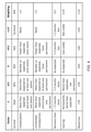
- Fig. 3 shows a table of surgical characteristics of the different surgical plans.
- Fig. 4 shows a table of measurement values and weightings used for determining an outcome score.
- Fig. 5 shows a table of surgical characteristics of ranked adjusted surgical plans.
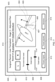
- Fig. 6 shows an example information processing device for receiving input information defining characteristics of a surgeon’s plan.
- Fig. 7 shows the example information processing device displaying information defining characteristics of an adjusted plan.
- Fig. 8 shows a surgical assistance method according to an embodiment.
- Fig. 9 shows a first example of a computer assisted surgery system to which the present technique is applicable.
- FIG. 10 shows a second example of a computer assisted surgery system to which the present technique is applicable.
- Fig. 11 shows a third example of a computer assisted surgery system to which the present technique is applicable.
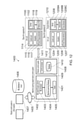
- Fig. 12 shows a fourth example of a computer assisted surgery system to which the present technique is applicable.
- Fig. 13 shows an example of an arm unit.
- Fig. 14 shows an example of a master console.
- Fig. 1 shows a surgical assistance system (apparatus) 200 according to an embodiment. It comprises a communication interface 201 for sending electronic information to and/or receiving electronic information from one or more electronic, a processor 202 for processing electronic instructions, a memory 203 for storing the electronic instructions to be processed and input and output data associated with the electronic instructions, a storage medium 204 (e.g. a hard disk drive, solid state drive or tape drive) for long term storage of data and a user interface 205 (e.g. a touch screen, a non-touch screen, buttons, a keyboard and/or a mouse) for receiving commands from and/or outputting information to a user.
- a communication interface 201 for sending electronic information to and/or receiving electronic information from one or more electronic
- a processor 202 for processing electronic instructions
- a memory 203 for storing the electronic instructions to be processed and input and output data associated with the electronic instructions
- a storage medium 204 e.g. a hard disk drive, solid state drive or tape drive
- Each of the communication interface 201, processor 202, memory 203, storage medium 204 and user interface 205 are implemented using appropriate circuitry, for example.
- the processor 202 controls the operation of each of the communication interface 201, memory 203, storage medium 204 and user interface 205.
- Fig. 2 shows part of the same type of surgical procedure being carried out according to different surgical plans.
- the surgical plans include a medical literature plan, an artificial intelligence (AI) optimal plan and a surgeon’s plan.
- the surgical procedure is a liver transplant.
- the part of the surgical procedure is a first incision of a blood vessel attached to the liver 101.
- Several characteristics of the surgery are different for different surgical plans. These are which blood vessel is subject to the first incision (the first incision blood vessel), the angle of the scalpel 104 relative to the horizontal when making the first incision (the view of the surgery in Fig. 2 is as seen by the surgeon carrying out the surgery) and the speed of the scalpel as the incision is made.
- characteristics are considered. However, in reality, a much larger number of characteristics may be considered. Other characteristics could include surgical strategy decisions (e.g. the route taken by a surgeon along a surgical decision tree comprising decisions such as surgical techniques to use, incision locations, tools to use and contingency plans for various expected complications - see US patent application US 20180247128, for example), surgical tool selection, surgical tool settings or the surgical tool manipulation type, grip position and/or force used by the surgeon, for example.
- the characteristics are summarised in the table of Fig. 3 and are recorded in the storage medium 204.
- the set of characteristics of the medical literature plan is taught by medical literature (e.g. a paper published in a relevant peer reviewed medical journal or published best-practice guidance issued by medical or surgical bodies).
- the medical literature is stored in electronic form in the storage medium 204 as part of a text searchable database of medical literature.
- the processor 202 Upon receiving input information at the user interface 205 indicating the surgical procedure or part of the surgical procedure being planned, the processor 202 performs a search of the database (e.g. using keywords such as “liver”, “transplant” and/or “incision”), parses the medical literature meeting the search constraints and determines the three characteristics taught by the medical literature.
- Any suitable known AI natural language processing algorithm may be used to help determine relevant medical literature and information within that medical literature (e.g. that pertaining to the three characteristics to be determined and surgical outcome information associated with those characteristics, for example).
- the medical literature found in the search may be reviewed manually and information indicative of the three characteristics manually entered via the user interface 205.
- the set of characteristics of the AI optimal plan is determined using a suitable AI algorithm or set of AI algorithms (e.g. one or more machine-learning algorithms).
- the processor 202 runs a machine-learning algorithm such as a neural network configured to receive input data indicating the three characteristics of the surgery and to output predicted surgical outcome information.
- the neural network is trained using historical values of the three characteristics and associated surgical outcome information. A number of different combinations of values of the three characteristics is input to the neural network and the three characteristic values which result in the most favourable surgical outcome information are determined to be the set of characteristics of the optimised AI plan.
- the set of characteristics of the surgeon’s plan is input via the user interface 205 by the surgeon. An example way of doing this described by Fig. 6.
- surgeon plans there may be other sources of surgical plans.
- the three characteristics and associated surgical outcome information of specific past surgeries performed by the surgeon or by another surgeon may be used to create a surgical plan.
- a different number of surgical plans may be used with the present technique. At least two surgical plans may be used with the present technique.
- first incision blood vessel there are two blood vessels which may be chosen, vessel 100L and vessel 100R (in reality, there may be a larger number of first incision blood vessels from which to choose).
- the medical literature and AI optimal plans choose vessel 100R as the first incision blood vessel.
- the surgeon’s plan chooses vessel 100L as the first incision blood vessel.
- the selected first incision blood vessel is detected by the processor 202 using images of the surgery captured by a surgical camera such as an endoscope or microscope (not shown) and transmitted to the communication interface 201.
- An object recognition technique is used to detect each blood vessel 100L and 100R in the image and to detect the first incision 102 made by the scalpel 104, thereby determining the first incision blood vessel.
- Any suitable object recognition technique known in the art e.g. a machine learning algorithm trained using previous images of blood vessels and incisions may be used.
- the field of view of the surgical site of the images captured for each past surgery is the same to allow the first incision blood vessel of each past surgery to be identified based on its position in the image relative to the other detected blood vessels (e.g. so vessel 100L always appears on the left and vessel 100R appears on the right as exemplified in Fig. 2).
- the scalpel angle 103A of the medical literature plan is recorded as 20°
- the scalpel angle 103B of the AI optimal plan is recorded as 45°
- the scalpel angle 103C of the surgeon’s plan is recorded as 25°.
- the scalpel angle is determined by the processor 202 for a past surgery (e.g. for training a neural network used in the AI optimal plan or determining the characteristics of a surgical plan based on a specific past surgery) again using images of the surgery.
- An object recognition technique is used to detect the scalpel 104 (e.g. using a machine learning algorithm trained using previous images of scalpels) and the angle of the scalpel may be determined using a predetermined mapping between scalpel orientation in the image and scalpel angle with the horizontal.
- the predetermined mapping is stored in the storage medium 204.
- a mapping between the 2D captured images of the surgical scene and a 3D model of the surgical scene is determined in advance and stored in the storage medium 204 to allow the scalpel angle to be determined from its orientation in the 2D captured images.
- 2D captured images of a single surgical scene may be simultaneously captured from a plurality of different fields of view (using a plurality of respective cameras) to improve the accuracy of the 2D to 3D mapping and therefore the accuracy of the determined scalpel angle.
- the scalpel may comprise a gyro sensor or the like (not shown) which determines the orientation of the scalpel relative to a determined direction.
- Data output by the gyro sensor (this data being an example of surgical tool data) is transmitted to the communication interface 201.
- a predetermined mapping between the gyro sensor data and the scalpel angle with the horizontal is stored in the storage medium 204 and used by the processor 202 to determine the scalpel angle.
- the medical literature plan has a scalpel speed of 2.5 cms -1 (centimetres per second)
- the AI optimal plan has a scalpel speed of 3.0 cms -1
- surgeon’s plan has a scalpel speed of 3.2 cms -1 .
- the scalpel speed is determined by the processor 202 for a past surgery (e.g. for training a neural network used in the AI optimal plan or determining the characteristics of a surgical plan based on a specific past surgery) again using images of the surgery.
- the change in position of the end of the scalpel 104 which intersects with the incision 102 (both the scalpel and incision previously having been detected as objects in the image) is tracked in successively captured images.
- the change in position is used together with (i) a predetermined mapping of image pixel pitch to distance in the surgical scene and (ii) the frame rate of the successively captured images to determine the speed at which the end of the scalpel is moving (and hence the speed at which the incision is being made).
- the scalpel speed is determined to be:
- the predetermined pixel pitch to distance mapping and frame rate is stored in the storage medium 204.
- the scalpel may comprise an accelerometer or the like (not shown) which determines the acceleration as the scalpel changes from being stationary (just before the surgeon starts the incision) to moving at a steady cutting speed (as the surgeon makes the incision).
- the acceleration (which is another example of surgical tool data) is multiplied by (or, for greater accuracy, numerically integrated over) the time period over which it occurs to determine the scalpel speed.
- the accelerometer is a six axis accelerometer (measuring both linear and rotational acceleration along each of three perpendicular axes) and the processor 202 distinguishes acceleration of the scalpel when making the incision from acceleration caused by other types of movement (e.g. when the surgeon initially picks up the scalpel).
- acceleration of the scalpel during making the incision is more likely to be linear along a relatively straight line with a low amount of rotational acceleration whereas acceleration when initially picking up the scalpel is more likely to include higher amounts of random rotational acceleration.
- the processor 202 may use a machine learning algorithm trained using previous examples of six axis acceleration of a scalpel during incision and during other types of movement to detect acceleration caused by an incision. When the start of an incision is detected, the processor 202 beings timing the acceleration to determine the scalpel speed.
- surgical characteristics of a past surgery may be determined from data collected by any suitable sensor or combination of sensors used in the surgery (e.g. on surgical instruments or a surgical robot used in the surgery).
- sensors may include optical sensors, time of flight sensors, accelerometers, pressure sensors, gyroscopes, infrared sensors, ultrasound probes or other relevant sensors.
- Optical sensors may include those found in smartphones, smart glasses, computers, operating room cameras, fluorescent microscopes or others.
- Surgical data generated from optical sensors could consist of RGB data or fluorescent imaging data (obtained by applying a fluorescent dye to the surgical site of the patient, for example) arranged in a 2D grid.
- Video processing algorithms can be used convert surgical data to 3D coordinate estimates.
- Fluorescence imaging may be used in combination with wavelengths of light outside of the visible spectrum. This may enable generation of surgical data from non-visible areas of the surgical site. Surgical data generated from time of flight sensors might be used to directly map the 3D surgical environment. Furthermore, Simultaneous Localisation And Mapping technology (SLAM) may be used to gather additional data of the 3D surgical environment.
- Example surgical instruments which may comprise such a sensor or set of sensors include scalpels, scissors, forceps, probes or cauterisers, for example.
- the table of Fig. 3 also shows an outcome score for each surgical plan.
- the outcome score indicates how successful the surgical procedure is likely to be for each of the surgical plans.
- the outcome score is determined from one or more factors known to be indicative of the success of a surgical procedure.
- Example factors include whether or not the patient survives the surgery, the existence and severity of complications arising in the surgery (e.g. events that occur which make the surgery more complicated and/or make it last longer), the existence and severity of unintended consequences of the surgery (e.g. a patient losing ability to do something they could do before the surgery), the patient’s recovery period, the amount of scarring and the quantity of blood loss.
- the one or more factors are measured for past surgeries (e.g. past surgeries whose characteristics are recorded directly by the surgical assistance system 200 in the ways exemplified above or past surgeries mentioned in medical literature) and the measurements are provided to the surgical assistance system 200 via the user interface 205 (in the case of manual entry of the measurements) and/or communication interface 201 (in the case of automated measurements).
- a measurement may be manually input for factors such as the amount of scarring, for example.
- An automated measurement may be input for factors such as the quantity of blood loss (e.g. based on input from a machine (not shown) monitoring the patient’s blood pressure which is able to estimate the amount of blood loss based on this). More generally, measurement values may be determined from electronic medical records, scans from medical nodes or voice recordings of a physician. The measurements are then used to generate the outcome score for each past surgery.
- the processor 202 e.g. the same neural network used to determine the AI optimal plan
- the outcome score may take any appropriate format.
- the outcome score takes a value of between +1 and -1.
- An outcome score of +1 is the best possible outcome.
- An outcome score of -1 is the worse possible outcome.
- An outcome score of 0 indicates an average outcome.
- each individual factor contributing to the outcome score is assigned a measurement value of between +1 and -1.
- An average of the measurement values of each factor is then determined as the outcome score.
- Some factors may be deemed more important than others in affecting patient outcome.
- the calculated average may therefore be a waited average with greater weightings given to factors deemed the most important.
- the most important factor is whether the patient survives the surgery. If the patient does not service the surgery, the outcome score is always recorded as -1 (i.e. the worse possible outcome). On the other hand, if the patient survives, the outcome score is recorded as the average or weighted average of the remaining factors.
- measurement values and weightings may be assigned for the factors mentioned above is shown in the table in Fig. 4. These may vary significantly for different types of surgery.
- the number and type of factors, how their measurement values are calculated (including the granularity of measurement values, e.g. a higher granularity so adjacent selectable measurement values are separated by, say, 0.25 instead of 0.5 is possible) and their weightings for different types of surgery may be determined in advance by experts in the medical community and stored in the storage medium 204.
- a measurement value of -1 is given if the patient does not survive the surgery.
- the outcome score is set as -1.
- a measurement value of +1 is given if the patient does survive the surgery.
- the outcome score is determined as the weighted average of the remaining factors. The remaining factors can each take a measurement value of -1, -0.5, 0, +0.5 and +1.
- the “complications” factor takes a value of 0 when the number of complications is as expected (e.g. within a threshold value equal to the average number of complications occurring for liver transplants in the medical community) and none of them are severe.
- a complication is classed as “severe” if one or more thresholds (e.g. the additional time added to the surgery because of the complication) are exceeded, for example.
- the “complications” factor takes a value of -0.5 if more complications occur than expected or if at least one of them is severe. It takes a value of 1 if both more complications occur than expected and at least one of them is severe. It takes a value of +0.5 if there are fewer complications than expected and none severe and a value of +1 if no complications occur.
- the “unintended consequences” factor takes a value of 0 when the number of unintended consequences is as expected (e.g. within a threshold value equal to the average number of unintended consequences occurring for liver transplants in the medical community) and none of them are permanent.
- An unintended consequence is classed as “permanent” if it is expected to cause the patient’s life to be permanently affected in a negative way (e.g. through chronic pain), for example.
- the “unintended consequences” factor takes a value of -0.5 if more unintended consequences occur than expected or if at least one of them is permanent. It takes a value of -1 if both more unintended consequences occur than expected and at least one of them is permanent. It takes a value of +0.5 if there are fewer unintended consequences than expected and none permanent and a value of +1 if no complications occur.
- the “recovery time” factor takes a value of 0 when the recovery time is as expected (e.g. within a month of the average recovery time for liver transplants in the medical community). It takes a value of -0.5 if the recovery time is 1-2 months more than expected and a value of -1 if the recovery time is more than 2 months more than expected. It takes a value of +0.5 if the recovery time is 1-2 months less than expected and a value of +1 if the recovery time is more than 2 months less than expected.
- the “scarring” factor takes a value of 0 when the amount of scarring is as expected. This is based, for example, on both initial scarring and how the scarring changes over time and is based on the opinion of the patient (e.g. who is contacted to give their opinion on the scarring at regular intervals after the surgery).
- the “scarring” factor takes a value of -0.5 if the scarring is worse than expected but not permanent (e.g. if the scarring is initially unacceptable to the patient but fades over time to an acceptable level). It takes a value of -1 if the scarring is worse than expected and permanent (e.g. if the scarring remains unacceptable to the patient even after a threshold amount of time, e.g. 1 year, has passed). It takes a value of +0.5 if the scarring is less visible than the patient expected and a value of +1 if the patient considers the scarring to not be visible at all.
- the “blood loss” factor takes a value of 0 when the amount of blood loss is more than 3% but less than or equal to 5% of the patient’s blood volume prior to the surgery. It takes a value of 0.5 if the amount of blood loss is more than 5% but less than or equal to 7%. It takes a value of -1 if the amount of blood loss is more than 7%. It takes a value of +0.5 if the amount of blood loss is more than 1% but less than or equal to 3%. It takes a value of +1 if the amount of blood loss is less than or equal to 1%.
- the amount of blood loss associated with each measurement value -1, -0.5, 0, +0.5 and 1 is determined based on the average amount of blood loss for liver transplants in the medical community, for example.
- this is done with a neural network implemented by the processor 202 (e.g. the same neural network used to generate the AI optimal plan).
- Sets of surgical characteristics used in respective past surgeries and outcome scores for those surgeries are used to train the neural network.
- the trained neural network can then be used to predict the outcome score associated with any set of surgical characteristics provided as an input to it.
- the characteristics mentioned in Fig. 3 for a plurality of past surgeries e.g. 500 real life and/or simulated surgeries either recorded directly by the surgical assistance system 200 during the surgery or derived from medical literature
- the respective outcomes of those surgeries may be used to train the network (e.g. with 400 of the surgeries being used as a training set and the remaining 100 surgeries being used as a test set to optimise the neural network parameters).
- trail combinations of characteristic values can be input to the neural network and the neural network then outputs an outcome score (of between -1 and 1 at a suitable granularity) using each combination.
- outcome score e.g. different combinations of first incision blood vessel, scalpel angle and scalpel speed
- This allows a set of characteristics to be tested and adjusted (e.g. within certain constraints) in order to predict the surgical outcome.
- This not only allows generation of the AI optimal plan (e.g. by trying lots of different sets of characteristic values and choosing the one of the tried sets which maximises the outcome score) but also allows the outcome score of the surgeon’s plan and, if necessary, the medical literature plan (e.g. if this isn’t indicated in the medical literature) to be predicted.
- the use of a neural network thus allows historical surgical characteristic and outcome data to be used to predict the outcome score associated any given set of surgical characteristics.
- the neural network may take into account other input data such as pre-operative patient data, genomic data, disease staging or general outcomes for all skilled surgeons, for example.
- the neural network may also be continually trained, e.g. by further training using the surgical characteristics and outcome information of the current surgery once the current surgery has been completed.
- Fig. 3 also shows an example adjustment probability for each surgical characteristic. This is the probability the surgeon who provided the surgeon’s plan will accept a suggestion to change that characteristic from that indicated in the surgeon’s plan.
- the probability of the surgeon adjusting the characteristic of first incision blood vessel from 100L to 100R is 0.5.
- the probability of the surgeon adjusting the characteristic of scalpel angle from 25° to another angle e.g. to 20° as indicated by the medical literature plan or to 45° as indicated by the AI optimal plan
- the probability of the surgeon adjusting the characteristic of scalpel speed from 3.2 cms -1 e.g. to 2.5 cms -1 as indicated by the medical literature plan or to 3.0 cms -1 as indicated by the AI optimal plan
- 0.8 is 0.8.
- the probabilities are stored in the storage medium 204.
- the probabilities are recorded in advance from past data indicating the propensity of the average surgeon to change each surgical characteristic.
- the probabilities may be adjusted over time for individual surgeons.
- each surgeon may have an electronic profile stored in the storage medium 204 which is accessible by that surgeon providing login details (e.g. a unique surgeon identifier and password) to the user interface 205.
- login details e.g. a unique surgeon identifier and password
- the surgeon’s propensity to accept changes to surgical plans they create is monitored over time and the probabilities of the surgeon changing each surgical characteristic are adjusted based on this. For example, for a given characteristic, if the surgeon does not accept a suggestion to change that characteristic a threshold number of times in a row, the probability of the surgeon changing that characteristic is reduced (e.g.
- the adjustment probability for the first incision blood vessel characteristic for a surgeon who refuses to change the first incision blood vessel from 100L to 100R when suggested to do so 3 times in a row will be reduced from 0.5 to 0.4.
- the adjustment probability for a surgeon who agrees to change the first incision blood vessel from 100L to 100R when suggested to do so 3 times in a row will be increased from 0.5 to 0.6.
- Other methods of adjusting the characteristic adjustment probabilities may be used.
- the characteristic probabilities may also be different depending on the extent of the change. For example, a larger change (e.g. of 15° or more for scalpel angle) may be associated with a lower probability than a smaller change (e.g. of 15° or less for scalpel angle).
- the surgical assistance system 200 Taking into account the surgeon’s adjustment probability for each surgical characteristic allows the surgical assistance system 200 to suggest changes to characteristics of the surgeon’s plan which both (a) improve the predicted outcome score for the surgery and (b) have a reasonable likelihood of being accepted by the surgeon.
- This allows information from multiple surgical plans to be used to arrive at a surgical plan which would not have been possible when considering only one of these sources.
- this allows input from medical literature and AI to be combined with the knowledge and experience of the surgeon (who may be aware of information not known from the medical literature or AI). Furthermore, it does this in a way which the surgeon may be more likely to accept.
- Fig. 5 shows example adjustments that may be made to the characteristics of the surgeon’s plan. These are referred to as adjusted plans.
- Each adjusted plan comprises a set of characteristics from one or more of the medical literature plan, AI optimal plan and surgeon’s plan.
- the predicted outcome score of the characteristics of each adjusted plan is then determined (e.g. using the above-mentioned neural network) and a predicted acceptability score indicated the propensity of the surgeon accepting the adjusted plan is determined.
- a total score is then determined from the combination of the predicted outcome score and predicted acceptability score. In this example, the total score is the sum of the predicted outcome score and predicted acceptability score.
- the plans are then ranked from highest to lower total score. The top ranking plan will therefore be the most beneficial plan taking into account both predicted outcome score (i.e. how successful the surgery is likely to be with the plan) and predicted acceptability score (i.e. how likely the surgeon is to accept the plan).
- the predicted outcome score is between -1 and +1 (as already described).
- the predicted acceptability score is also between -1 and +1. This means the total score ranges from -2 to +2.
- the predicted acceptability score of each adjusted plan is determined using the compound probability of the surgeon making the required surgical characteristic changes to implement the adjusted plan.
- the compound probability p is then used to determine the predicted acceptability score using the formula:
- any combination of characteristics may be used to blindly determine an adjusted plan and its corresponding total score.
- the processor 202 trials different combinations of characteristics by comparing characteristics of the medical literature plan, AI optimal plan and surgeon’s plan and adjusting characteristics of the surgeon’s plan in a way which may improve the predicted outcome score of the surgeon’s plan. It does this by first determining an initial adjusted plan.
- the processor 202 determines the initial adjusted plan by taking the surgeon’s plan and making one or more characteristics of the surgeon’s plan an average value of those one or more characteristics of the medical literature plan, AI optimal plan and surgeon’s plan. If the characteristic is continuously variable (e.g. the scalpel angle or scalpel speed), the average may be the mean. If the characteristic is not continuously variable (e.g. the first incision blood vessel), the average may be the mode. In another example, the one or more characteristics of the initial adjusted plan are set equal to the value of those one or more characteristics in one of the medical literature plan, AI optimal plan and surgeon’s plan with the best predicted outcome score. Different characteristics of the initial adjusted plan may be determined in different ways (e.g. one characteristic using the average and another characteristic using that of the medical literature plan, AI optimal plan and surgeon’s plan with the best predicted outcome score).
- the one or more characteristics of the surgeon’s plan which are adjusted to determine the initial adjusted plan are chosen based on the adjustment probability for that characteristic. For example, all characteristics with an adjustment probability above a predetermined threshold (e.g. 0.6) may be adjusted or a predetermined number of characteristics in descending rank order of adjustment probability (i.e. starting with the highest adjustment probability) may be adjusted.
- a predetermined threshold e.g. 0.6
- a predetermined number of characteristics in descending rank order of adjustment probability i.e. starting with the highest adjustment probability
- the processor 202 may adjust each characteristic of the initial adjusted plan to take a plurality of values within a predetermined range (e.g. up to and including +/- 5° of the scalpel angle of the initial adjusted plan in steps of 1° or up to including +/- 0.5 cms -1 of the scalpel speed of the initial adjusted plan in steps of 0.1 cms -1 ).
- a predetermined range e.g. up to and including +/- 5° of the scalpel angle of the initial adjusted plan in steps of 1° or up to including +/- 0.5 cms -1 of the scalpel speed of the initial adjusted plan in steps of 0.1 cms -1 ).
- the processor may adjust each characteristic so that it takes each possible one of its values (e.g. 100L or 100R as the first incision blood vessel). In this way, additional adjusted plans each comprising a different combination of characteristics are determined.
- the processor 202 is thus able to use the plans other than the surgeon’s plan (the medical literature plan and AI optimal plan in the example of Fig. 3) to determine an initial adjusted plan based on what is likely to make a positive difference to the surgical outcome and adjustments the surgeon is likely to accept.
- the characteristics of the initial adjusted plan are then adjusted (e.g. within predetermined constraints) to try to find additional adjusted plans and their corresponding total scores.
- the additional adjusted plans are then ranked by total score.
- Fig. 5 shows an example of the top 3 adjusted plans based on the medical literature plan, AI optimal plan and surgeon’s plan of Fig. 3.
- the highest ranking plan by total score involves the surgeon maintaining the scalpel angle (25°) and scalpel speed (3.2 cms -1 ) of the surgeon’s plan but changing the first incision blood vessel from 100L to 100R. This results in a predicted outcome score of +0.60. This is an improvement compared to the predicted outcome score of the surgeon’s plan of -0.25.
- the probability of the surgeon changing this characteristic according to Fig. 3 is 0.5, thereby resulting in a predicted acceptability score of 0.00.
- the next highest ranking plan by total score involves the surgeon maintaining the first incision blood vessel (100L) and scalpel angle (25°) of the surgeon’s plan but changing the scalpel speed from 3.2 cms -1 to 3.0 cms -1 .
- the probability of the surgeon changing this characteristic according to Fig. 3 is 0.8, thereby resulting in a predicted acceptability score of +0.60.
- the next highest ranking plan by total score involves the surgeon changing all three characteristics of the surgeon’s plan. Namely, it involves changing the first incision blood vessel from 100L to 100R, changing the scalpel angle from 25° to 45° and changing the scalpel speed from 3.2 cms -1 to 3.0 cms -1 . It is noted this happens to result in the AI optimal plan which has a predicted outcome score of +0.75. This is an improvement compared to the predicted outcome score of the surgeon’s plan of -0.25.
- the optimal adjusted plan i.e. the rank 1 plan
- AI optimal plan and surgeon’s plan initially suggested uses characteristics of these plans to determine an initial adjusted plan and then optimises the characteristics of the initial adjusted plan using historical surgical characteristic and outcome data (e.g. by way of a neural network) and knowledge of the surgeon’s propensity to make adjustments to a planned surgical procedure (e.g. the adjustment probabilities).
- the result is a plan which is likely to both (a) improve surgical outcome and (b) be acceptable to the surgeon.
- the AI optimal plan has the best predicted outcome score, it may not be possible for the surgeon to blindly follow this, especially if it conflicts with the surgeon’s own knowledge and experience and/or the medical literature.
- the high predicted outcome score of the AI optimal plan means the surgeon may benefit from at least considering the characteristics of the AI optimal plan. The present technique therefore helps reduce the uncertainty experienced by a surgeon when multiple, potentially conflicting surgical plans are possible.
- the initial set of surgical plans used to generate the ranked adjusted plans include a surgeon’s plan.
- the initial set of surgical plans may consist of a plurality of AI generated plans each generated using a different respective AI (e.g. using different types of neural networks and/or a neural network and another type of machine learning algorithm).
- the ranked adjusted plans may be generated in the same way using one of the AI generated plans as a reference instead of the surgeon’s plan.
- the adjustment probability of the surgeon of each surgical characteristic of the AI generated plans is still recorded in the storage medium 204 and used in determining the total score and rankings of the adjusted plans.
- Fig. 6 shows an information processing device 600 to which a surgeon has access.
- the device 600 is a tablet computer comprising a touch screen 601.
- the device 600 and surgical assistance system 200 are one and the same (and the user interface 205 therefore takes the form of the touch screen 601).
- the device 600 and surgical assistance system 200 are separate devices and information is exchanged between the device 600 and communication interface 201 of the surgical assistance system over a network (e.g. the internet or a hospital intranet).
- the device may take alternative forms and/or may receive input from and/or output information to the surgeon in different ways. This includes voice input, text input, a video interface, use of smart surgical tools or surgical robots and/or other known human-machine interaction methods, for example.
- the device 600 is configured to run a software application (app) which provides a graphical user interface GUI 603 for allowing the surgeon to input information indicating the characteristics of the surgeon’s plan for the stage of the liver transplant about to be performed.
- the stage to be performed is the making of incision 102.
- the surgeon is notified of the stage to be performed (“Stage 3”) and the need for information indicating the characteristics of the surgeon’s plan to be entered (“Input Plan”) by text 611.
- the surgeon indicates the first incision blood vessel 100L or 100R using the selectable virtual buttons 610.
- the “L” button selects blood vessel 100L
- the “R” button selects blood vessel 100R.
- An animation 605 is shown indicating the position of the liver 101 and blood vessels 100L and 100R.
- the blood vessels 100L and 100R are indicated in the animation by respective “L” and “R” animated arrows 604.
- a scalpel animation 606 representing the position of the scalpel appears in the animation.
- the “L” virtual button is selected (its selection is indicated by it being displayed in a different colour to the “R” virtual button) and, as a result, the scalpel animation 606 is positioned next to and appears to make an incision in the blood vessel 100L.
- the scalpel angle is adjustable from 0° to 90° (becoming smaller when the virtual slider is slid to the left and large when the virtual slider is slid to the right) and, in response to adjusting the scalpel angle, the angle 607 of the scalpel animation 606 is correspondingly adjusted. This allows the surgeon to visualise the effect of changing the scalpel angle.
- the surgeon then adjusts the scalpel speed using the virtual slider 608.
- the scalpel speed is adjustable from 0 cms1 to 5 cms -1 (becoming smaller when the virtual slider is slid to the left and large when the virtual slider is slid to the right).
- the scalpel animation 606 is caused to simulate an incision at a speed corresponding to the selected scalpel speed. This allows the surgeon to visualise the effect of changing the scalpel speed.
- surgeons plan in this example is the surgeon’s plan exemplified in Fig. 3.
- a set of ranked adjusted plans are then determined by the processor 202 in the way as previously described (e.g. using the surgeon’s plan in combination with the medical literature plan and AI optimal plan).
- the resulting top ranked adjusted plan is then displayed to the surgeon via the GUI. This is shown in Fig. 7.
- the top ranked adjusted plan is displayed to the surgeon via the touch screen controls 608 to 610 and the animation 605.
- This provides a consistent, easy to use interface for the surgeon to compare the surgeon’s plan with the top ranked adjusted plan.
- the top ranked adjusted plan here is the rank 1 plan of Fig. 5.
- the surgeon is able to quickly see that the first incision blood vessel has changed from “L” to “R” (with the “R” virtual button being displayed in a different colour to the “L” virtual button to indicate its selection and the scalpel animation 606 being positioned next to and appearing to make an incision in the blood vessel 100R).
- the text 613 again notifies the surgeon of the surgical stage to be performed (“Stage 3”) and that the indicated characteristics on-screen are those of the top ranked adjusted plan (“Adjusted Plan”).
- the text also includes selectable links “AI analysis” and “medical literature”.
- AI analysis and “medical literature”.
- the device 600 displays information about how the AI optimal plan was determined. This can include information on the historical surgical characteristic and outcome data used to train the neural network or the parameters of the neural network, for example. It may also include the outcome score of the AI optimal plan (and, optionally, the outcome score of the surgeon’s plan to aid comparison by the surgeon).
- the “medical literature” link being selected, the device 600 displays information about how the medical literature plan was determined.
- the “AI analysis” and “medical literature” information may be presented to the surgeon in any suitable way including text, diagrams, audio, video or an interactive GUI, for example.
- surgeon wishes to proceed with the adjusted plan, they select the “Proceed (adjusted)” virtual button 614. Prior to doing this (e.g. after reviewing the information obtained by selecting the “AI analysis” and/or “medical literature” links), the surgeon may make further adjustments to the characteristics of the adjusted plan using the virtual controls 608 to 610.
- the users may choose to accept the change in first incision blood vessel from vessel 100L to 100R but also, having reviewed the information obtained by selecting the “AI analysis” and/or “medical literature” links, reduce the scalpel speed from 3.2 cms -1 (originally specified by the surgeon’s plan and kept in the top ranked adjusted plan) to a reduced speed such as 3.0 cms -1 (since both the medical literature plan and AI optimal plan recommend a lower scalpel speed than 3.2 cms -1 ). Selecting the virtual button 614 allows the surgery to proceed with whatever set of characteristics are currently selected using the screen of Fig. 7.
- surgeons do not wish to proceed with the adjusted plan, they select the “Proceed (original)” virtual button 613.
- This provides a quick and easy way for the surgeon to reject the adjusted plan and proceed with the surgeon’s plan in original form. This is desirable if, for example, the surgeon has information specific to the current surgery which is not known to the AI used to generate the AI optimal plan or the medical literature and which means the surgeon’s original plan is the most appropriate plan. Selecting the virtual button 613 allows the surgery to proceed with the original set of characteristics of the surgeon’s plan.
- the adjusted plan displayed in Fig. 7 is the top ranked adjusted plan.
- the surgeon is able to view the other adjusted plans and their rankings (e.g. by the device 600 displaying a table like that exemplified in Fig. 5).
- Each alternative adjusted plan is selectable and, in response to being selected, the characteristics of that alternative adjusted plan are displayed using the virtual controls 608 to 610 and animation 605 of Fig. 7 in the same way as previously described.
- the virtual controls 608 to 610 may be used to adjust individual parameters of whichever alternative plan is selected. Selecting the virtual button 614 then allows the surgery to proceed with whatever set of characteristics are currently selected using the screen of Fig. 7.
- the device 600 performs any preconfigured function to help the surgeon perform the surgery (e.g. displaying of information or control of a surgical robot) according to the selected set of characteristics. Alternatively or in addition, the device 600 may proceed to a screen like that exemplified in Fig. 6 to allow the surgeon to input the surgical characteristics of the next stage of the surgical procedure. The process is then repeated.
- any preconfigured function to help the surgeon perform the surgery (e.g. displaying of information or control of a surgical robot) according to the selected set of characteristics.
- the device 600 may proceed to a screen like that exemplified in Fig. 6 to allow the surgeon to input the surgical characteristics of the next stage of the surgical procedure. The process is then repeated.
- the processor 202 Upon selecting the “Proceed (original)” or “Proceed (adjusted)” virtual button, the processor 202 stores a record in the storage medium 204 indicating any characteristic for which a change was recommended but rejected. A running total of rejections for each characteristic is recorded in this way and compared to a threshold (e.g. a threshold of 3 as previously discussed). Once the threshold number of rejections is met, the adjustment probability associated with the characteristic is reduced (e.g. by 0.1) and the running total of rejections for the characteristic reset. The processor 202 also stores a record in the storage medium 204 indicating any characteristic for which a change was accepted. An accepted change may be acceptance of a specific change recommended by the adjusted plan displayed in Fig. 7 (e.g.
- an accepted change may be any change of a characteristic from that specified in the surgeon’s plan (e.g. if the surgeon accepts a scalpel speed of any value other than the original 3.2 cms -1 scalpel speed of the surgeon’s plan or a scalpel angle of any value other than the original 25° scalpel angle of the surgeon’s plan).
- a running total of accepted changes for each characteristic is recorded in this way and compared to a threshold (e.g. a threshold of 3 as previously discussed). Once the threshold number of accepted changes is met, the adjustment probability associated with the characteristic is increased (e.g. by 0.1) and the running total of accepted changes for the characteristic reset.
- the processor 202 may instead output information indicating only the highest ranked adjusted plan as a single adjusted plan. This single adjusted plan is then displayed (e.g. as exemplified in Fig. 7) and the “Alternatives” virtual button 615 may be omitted.
- Fig. 6 involves the surgeon manually entering the surgical characteristics of the surgeon’s plan.
- the characteristics of the surgeon’s plan for the next stage of surgery may be determined automatically based on the surgeon’s characteristics in the current stage of surgery (as determined using the same image processing techniques described for determining the first incision blood vessel, scalpel angle and scalpel speed in previous surgeries, for example). For example, there may be a previously established relationship derivable from information recorded during previous surgeries of the surgeon between the characteristics in one stage of surgery and the characteristics in a subsequent stage of surgery. This relationship can be used to predict the characteristics of the subsequent stage of surgery. These may then be automatically recorded as the surgeon’s plan.
- surgeon’s plan may be used to determine default characteristic values which can then be viewed, adjusted (if necessary) and confirmed (e.g. using a screen like that exemplified in Fig. 6) prior to creation of the surgeon’s plan. This makes it quicker and easier for the surgeon to define the characteristics of the surgeon’s plan.
- image processing or the like is performed by the processor 202 (with appropriate inputs to the communication interface 201 such as a live video feed of the surgery) to monitor the characteristics of the surgery in real time. If the surgeon is detected as deviating from the accepted plan, the surgeon is alerted (e.g. via an audible, visual and/or haptic alert).
- an adjusted plan is only determined when the two or more input plans (e.g. surgeon’s plan, AI optimal plan and medical literature plan) are different or, more specifically, differ by a determined threshold amount in one or more characteristics and/or outcome score.
- all input plans including the surgeon’s plan
- a scalpel angle within a range of +/-5° of each other
- a scalpel speed of within a range of +/- 0.5 cms -1 of each other and/or an outcome score within +/- 0.2 of each other
- the screen of Fig. 7 is skipped when the user selects the “Proceed” virtual button 612 and the user is instead presented with a message saying “Proceed with Surgeon’s Plan” or similar.
- Fig. 9 shows a surgical assistance method carried out by the surgical assistance system 200 according to an embodiment.
- the method starts at step 900.
- the processor 202 obtains first surgical information indicating a characteristic of a surgery associated with a first information source.
- the first information source is one of a first surgeon (e.g. to generate a first surgeon’s plan), a first previous surgery (i.e. a first real surgery which has previously taken place), a first simulated surgery (i.e. a first surgery simulated using a surgical dummy or virtual reality system, for example), a first artificial intelligence (e.g. to generate a first AI optimal plan) and first medical literature (e.g. to generate a first medical literature plan), for example.
- the first incision blood vessel, scalpel angle and scalpel speed chosen by the first information source are each an example of a characteristic associated with the first information source.
- the processor 202 obtains second surgical information indicating a characteristic of the surgery associated with a second information source.
- the second information source is one of a second surgeon (e.g. to generate a second surgeon’s plan), a second previous surgery (i.e. a second real surgery which has previously taken place), a second simulated surgery (i.e. a second surgery simulated using a surgical dummy or virtual reality system, for example), a second artificial intelligence (e.g. to generate a second AI optimal plan) and second medical literature (e.g. to generate a second medical literature plan), for example.
- the first incision blood vessel, scalpel angle and scalpel speed chosen by the second information source are each an example of a characteristic associated with the second information source.
- the processor 202 determines third surgical information indicating a recommended characteristic of the surgery using the first and second surgical information, outcome information associated with the first and second surgical information and a characteristic of a surgeon.
- the first incision blood vessel, scalpel angle and scalpel speed of an adjusted plan are each an example of a recommended characteristic.
- the outcome score of each of the surgeon’s plan, AI optimal plan and medical literature plan is an example of outcome information.
- the adjustment probability of the surgeon for each of the first incision blood vessel, scalpel angle and scalpel speed is an example of a characteristic of a surgeon. As exemplified in Fig.
- the outcome score and adjustment probability of a given set of surgical characteristics can be used to determine a “total score” associated with that set of characteristics.
- the set of characteristics with the highest “total score” is then output as the top ranked adjusted plan.
- the plans of the exemplified embodiments comprise multiple surgical characteristics (i.e. first incision blood vessel, scalpel angle and scalpel speed), the present technique is applicable to plans specifying at least one characteristic.
- the processor 202 controls the third surgical information to be output for use by the surgeon.
- the third surgical information is output using a GUI like that of Fig. 7.
- the method ends at step 905.
- the present technique thus allows a final surgical plan to be constructed from multiple input plans.
- Those input plans may include surgical characteristics recommended by one or more human surgeons, one or more AI techniques and/or medical literature, for example.
- the final surgical plan is a plan which comprises between the input plans in a way which is likely to increase the chance of a successful surgical outcome and which is likely to be acceptable to the surgeon. It ensures the surgeon is provided with more information to make informed decisions about the surgery. It also helps to nudge a surgeon towards best practice over time based on evidence of surgical characteristics and outcomes from multiple sources.
- Fig. 10 schematically shows an example of a computer assisted surgery system 1126 to which the present technique is applicable.
- the computer assisted surgery system is a master-slave (master slave) system incorporating an autonomous arm 1100 and one or more surgeoncontrolled arms 1101.
- the autonomous arm holds an imaging device 1102 (e.g. a surgical camera or medical vision scope such as a medical endoscope, surgical microscope or surgical exoscope).
- the one or more surgeon-controlled arms 1101 each hold a surgical device 1103 (e.g. a cutting tool or the like).
- the imaging device of the autonomous arm outputs an image of the surgical scene to an electronic display 1110 viewable by the surgeon.
- the autonomous arm autonomously adjusts the view of the imaging device whilst the surgeon performs the surgery using the one or more surgeon-controlled arms to provide the surgeon with an appropriate view of the surgical scene in real time.
- the surgeon controls the one or more surgeon-controlled arms 1101 using a master console 1104.
- the master console includes a master controller 1105.
- the master controller 1105 includes one or more force sensors 1106 (e.g. torque sensors), one or more rotation sensors 1107 (e.g. encoders) and one or more actuators 1108.
- the master console includes an arm (not shown) including one or more joints and an operation portion. The operation portion can be grasped by the surgeon and moved to cause movement of the arm about the one or more joints.
- the one or more force sensors 1106 detect a force provided by the surgeon on the operation portion of the arm about the one or more joints.
- the one or more rotation sensors detect a rotation angle of the one or more joints of the arm.
- the actuator 1108 drives the arm about the one or more joints to allow the arm to provide haptic feedback to the surgeon.
- the master console includes a natural user interface (NUI) input / output for receiving input information from and providing output information to the surgeon.
- the NUI input / output includes the arm (which the surgeon moves to provide input information and which provides haptic feedback to the surgeon as output information).
- the NUI input / output may also include voice input, line of sight input and/or gesture input, for example.
- the master console comprises the electronic display 1110 for outputting images captured by the imaging device 1102.
- the master console 1104 communicates with each of the autonomous arm 1100 and one or more surgeon-controlled arms 1101 via a robotic control system 1111.
- the robotic control system is connected to the master console 1104, autonomous arm 1100 and one or more surgeon-controlled arms 1101 by wired or wireless connections 1123, 1124 and 1125.
- the connections 1123, 1124 and 1125 allow the exchange of wired or wireless signals between the master console, autonomous arm and one or more surgeon-controlled arms.
- the robotic control system includes a control processor 1112 and a database 1113.
- the control processor 1112 processes signals received from the one or more force sensors 1106 and one or more rotation sensors 1107 and outputs control signals in response to which one or more actuators 1116 drive the one or more surgeon controlled arms 1101. In this way, movement of the operation portion of the master console 1104 causes corresponding movement of the one or more surgeon controlled arms.
- the control processor 1112 also outputs control signals in response to which one or more actuators 1116 drive the autonomous arm 1100.
- the control signals output to the autonomous arm are determined by the control processor 1112 in response to signals received from one or more of the master console 1104, one or more surgeon-controlled arms 1101, autonomous arm 1100 and any other signal sources (not shown).
- the received signals are signals which indicate an appropriate position of the autonomous arm for images with an appropriate view to be captured by the imaging device 1102.
- the database 1113 stores values of the received signals and corresponding positions of the autonomous arm.
- a corresponding position of the autonomous arm 1100 is set so that images captured by the imaging device 1102 are not occluded by the one or more surgeon-controlled arms 1101.
- a corresponding position of the autonomous arm is set so that images are captured by the imaging device 1102 from an alternative view (e.g. one which allows the autonomous arm to move along an alternative path not involving the obstacle).
- the control processor 1112 looks up the values of the received signals in the database 1112 and retrieves information indicating the corresponding position of the autonomous arm 1100. This information is then processed to generate further signals in response to which the actuators 1116 of the autonomous arm cause the autonomous arm to move to the indicated position.
- Each of the autonomous arm 1100 and one or more surgeon-controlled arms 1101 includes an arm unit 1114.
- the arm unit includes an arm (not shown), a control unit 1115, one or more actuators 1116 and one or more force sensors 1117 (e.g. torque sensors).
- the arm includes one or more links and joints to allow movement of the arm.
- the control unit 1115 sends signals to and receives signals from the robotic control system 1111.
- the control unit 1115 controls the one or more actuators 1116 to drive the arm about the one or more joints to move it to an appropriate position.
- the received signals are generated by the robotic control system based on signals received from the master console 1104 (e.g. by the surgeon controlling the arm of the master console).
- the received signals are generated by the robotic control system looking up suitable autonomous arm position information in the database 1113.
- the control unit 1115 In response to signals output by the one or more force sensors 1117 about the one or more joints, the control unit 1115 outputs signals to the robotic control system. For example, this allows the robotic control system to send signals indicative of resistance experienced by the one or more surgeon-controlled arms 1101 to the master console 1104 to provide corresponding haptic feedback to the surgeon (e.g. so that a resistance experienced by the one or more surgeon-controlled arms results in the actuators 1108 of the master console causing a corresponding resistance in the arm of the master console). As another example, this allows the robotic control system to look up suitable autonomous arm position information in the database 1113 (e.g. to find an alternative position of the autonomous arm if the one or more force sensors 1117 indicate an obstacle is in the path of the autonomous arm).
- the imaging device 1102 of the autonomous arm 1100 includes a camera control unit 1118 and an imaging unit 1119.
- the camera control unit controls the imaging unit to capture images and controls various parameters of the captured image such as zoom level, exposure value, white balance and the like.
- the imaging unit captures images of the surgical scene.
- the imaging unit includes all components necessary for capturing images including one or more lenses and an image sensor (not shown). The view of the surgical scene from which images are captured depends on the position of the autonomous arm.
- the surgical device 1103 of the one or more surgeon-controlled arms includes a device control unit 1120, manipulator 1121 (e.g. including one or more motors and/or actuators) and one or more force sensors 1122 (e.g. torque sensors).
- manipulator 1121 e.g. including one or more motors and/or actuators
- force sensors 1122 e.g. torque sensors
- the device control unit 1120 controls the manipulator to perform a physical action (e.g. a cutting action when the surgical device 1103 is a cutting tool) in response to signals received from the robotic control system 1111.
- the signals are generated by the robotic control system in response to signals received from the master console 1104 which are generated by the surgeon inputting information to the NUI input / output 1109 to control the surgical device.
- the NUI input / output includes one or more buttons or levers comprised as part of the operation portion of the arm of the master console which are operable by the surgeon to cause the surgical device to perform a predetermined action (e.g. turning an electric blade on or off when the surgical device is a cutting tool).
- the device control unit 1120 also receives signals from the one or more force sensors 1122. In response to the received signals, the device control unit provides corresponding signals to the robotic control system 1111 which, in turn, provides corresponding signals to the master console 1104.
- the master console provides haptic feedback to the surgeon via the NUI input / output 1109. The surgeon therefore receives haptic feedback from the surgical device 1103 as well as from the one or more surgeon-controlled arms 1101.
- the haptic feedback involves the button or lever which operates the cutting tool to give greater resistance to operation when the signals from the one or more force sensors 1122 indicate a greater force on the cutting tool (as occurs when cutting through a harder material, e.g.
- the NUI input / output 1109 includes one or more suitable motors, actuators or the like to provide the haptic feedback in response to signals received from the robot control system 1111.
- Fig. 11 schematically shows another example of a computer assisted surgery system 1209 to which the present technique is applicable.
- the computer assisted surgery system 1209 is a surgery system in which the surgeon performs tasks via the master-slave system 1126 and a computerised surgical apparatus 1200 performs tasks autonomously.
- the master-slave system 1126 is the same as Fig. 10 and is therefore not described.
- the master-slave system may, however, be a different system to that of Fig. 10 in alternative embodiments or may be omitted altogether (in which case the system 1209 works autonomously whilst the surgeon performs conventional surgery).
- the computerised surgical apparatus 1200 includes a robotic control system 1201 and a tool holder arm apparatus 1210.
- the tool holder arm apparatus 1210 includes an arm unit 1204 and a surgical device 1208.
- the arm unit includes an arm (not shown), a control unit 1205, one or more actuators 1206 and one or more force sensors 1207 (e.g. torque sensors).
- the arm comprises one or more joints to allow movement of the arm.
- the tool holder arm apparatus 1210 sends signals to and receives signals from the robotic control system 1201 via a wired or wireless connection 1211.
- the robotic control system 1201 includes a control processor 1202 and a database 1203. Although shown as a separate robotic control system, the robotic control system 1201 and the robotic control system 1111 may be one and the same.
- the surgical device 1208 has the same components as the surgical device 1103. These are not shown in Fig. 11.
- control unit 1205 controls the one or more actuators 1206 to drive the arm about the one or more joints to move it to an appropriate position.
- the operation of the surgical device 1208 is also controlled by control signals received from the robotic control system 1201.
- the control signals are generated by the control processor 1202 in response to signals received from one or more of the arm unit 1204, surgical device 1208 and any other signal sources (not shown).
- the other signal sources may include an imaging device (e.g. imaging device 1102 of the master-slave system 1126) which captures images of the surgical scene.
- the values of the signals received by the control processor 1202 are compared to signal values stored in the database 1203 along with corresponding arm position and/or surgical device operation state information.
- the control processor 1202 retrieves from the database 1203 arm position and/or surgical device operation state information associated with the values of the received signals. The control processor 1202 then generates the control signals to be transmitted to the control unit 1205 and surgical device 1208 using the retrieved arm position and/or surgical device operation state information.
- signals received from an imaging device which captures images of the surgical scene indicate a predetermined surgical scenario (e.g. via neural network image classification process or the like)
- the predetermined surgical scenario is looked up in the database 1203 and arm position information and/or surgical device operation state information associated with the predetermined surgical scenario is retrieved from the database.
- signals indicate a value of resistance measured by the one or more force sensors 1207 about the one or more joints of the arm unit 1204
- the value of resistance is looked up in the database 1203 and arm position information and/or surgical device operation state information associated with the value of resistance is retrieved from the database (e.g. to allow the position of the arm to be changed to an alternative position if an increased resistance corresponds to an obstacle in the arm’s path).
- control processor 1202 then sends signals to the control unit 1205 to control the one or more actuators 1206 to change the position of the arm to that indicated by the retrieved arm position information and/or signals to the surgical device 1208 to control the surgical device 1208 to enter an operation state indicated by the retrieved operation state information (e.g. turning an electric blade to an “on” state or “off” state if the surgical device 1208 is a cutting tool).
- an operation state indicated by the retrieved operation state information e.g. turning an electric blade to an “on” state or “off” state if the surgical device 1208 is a cutting tool.
- Fig. 12 schematically shows another example of a computer assisted surgery system 1300 to which the present technique is applicable.
- the computer assisted surgery system 1300 is a computer assisted medical scope system in which an autonomous arm 1100 holds an imaging device 1102 (e.g. a medical scope such as an endoscope, microscope or exoscope).
- the imaging device of the autonomous arm outputs an image of the surgical scene to an electronic display (not shown) viewable by the surgeon.
- the autonomous arm autonomously adjusts the view of the imaging device whilst the surgeon performs the surgery to provide the surgeon with an appropriate view of the surgical scene in real time.
- the autonomous arm 1100 is the same as that of Fig. 10 and is therefore not described.
- the autonomous arm is provided as part of the standalone computer assisted medical scope system 1300 rather than as part of the master-slave system 1126 of Fig. 10.
- the autonomous arm 1100 can therefore be used in many different surgical setups including, for example, laparoscopic surgery (in which the medical scope is an endoscope) and open surgery.
- the computer assisted medical scope system 1300 also includes a robotic control system 1302 for controlling the autonomous arm 1100.
- the robotic control system 1302 includes a control processor 1303 and a database 1304. Wired or wireless signals are exchanged between the robotic control system 1302 and autonomous arm 1100 via connection 1301.
- control unit 1115 controls the one or more actuators 1116 to drive the autonomous arm 1100 to move it to an appropriate position for images with an appropriate view to be captured by the imaging device 1102.
- the control signals are generated by the control processor 1303 in response to signals received from one or more of the arm unit 1114, imaging device 1102 and any other signal sources (not shown).
- the values of the signals received by the control processor 1303 are compared to signal values stored in the database 1304 along with corresponding arm position information.
- the control processor 1303 retrieves from the database 1304 arm position information associated with the values of the received signals.
- the control processor 1303 then generates the control signals to be transmitted to the control unit 1115 using the retrieved arm position information.
- signals received from the imaging device 1102 indicate a predetermined surgical scenario (e.g. via neural network image classification process or the like)
- the predetermined surgical scenario is looked up in the database 1304 and arm position information associated with the predetermined surgical scenario is retrieved from the database.
- signals indicate a value of resistance measured by the one or more force sensors 1117 of the arm unit 1114
- the value of resistance is looked up in the database 1203 and arm position information associated with the value of resistance is retrieved from the database (e.g. to allow the position of the arm to be changed to an alternative position if an increased resistance corresponds to an obstacle in the arm’s path).
- the control processor 1303 then sends signals to the control unit 1115 to control the one or more actuators 1116 to change the position of the arm to that indicated by the retrieved arm position information.
- Fig. 13 schematically shows another example of a computer assisted surgery system 1400 to which the present technique is applicable.
- the system includes one or more autonomous arms 1100 with an imaging unit 1102 and one or more autonomous arms 1210 with a surgical device 1210.
- the one or more autonomous arms 1100 and one or more autonomous arms 1210 are the same as those previously described.
- Each of the autonomous arms 1100 and 1210 is controlled by a robotic control system 1408 including a control processor 1409 and database 1410. Wired or wireless signals are transmitted between the robotic control system 1408 and each of the autonomous arms 1100 and 1210 via connections 1411 and 1412, respectively.
- the robotic control system 1408 performs the functions of the previously described robotic control systems 1111 and/or 1302 for controlling each of the autonomous arms 1100 and performs the functions of the previously described robotic control system 1201 for controlling each of the autonomous arms 1210.
- the autonomous arms 1100 and 1210 perform at least a part of the surgery completely autonomously (e.g. when the system 1400 is an open surgery system).
- the robotic control system 1408 controls the autonomous arms 1100 and 1210 to perform predetermined actions during the surgery based on input information indicative of the current stage of the surgery and/or events happening in the surgery.
- the input information includes images captured by the image capture device 1102.
- the input information may also include sounds captured by a microphone (not shown), detection of in-use surgical instruments based on motion sensors comprised with the surgical instruments (not shown) and/or any other suitable input information.
- the input information is analysed using a suitable machine learning (ML) algorithm (e.g. a suitable artificial neural network) implemented by machine learning based surgery planning apparatus 1402.
- ML machine learning
- the planning apparatus 1402 includes a machine learning processor 1403, a machine learning database 1404 and a trainer 1405.
- the machine learning database 1404 includes information indicating classifications of surgical stages (e.g. making an incision, removing an organ or applying stitches) and/or surgical events (e.g. a bleed or a patient parameter falling outside a predetermined range) and input information known in advance to correspond to those classifications (e.g. one or more images captured by the imaging device 1102 during each classified surgical stage and/or surgical event).
- the machine learning database 1404 is populated during a training phase by providing information indicating each classification and corresponding input information to the trainer 1405.
- the trainer 1405 uses this information to train the machine learning algorithm (e.g. by using the information to determine suitable artificial neural network parameters).
- the machine learning algorithm is implemented by the machine learning processor 1403.
- previously unseen input information e.g. newly captured images of a surgical scene
- the machine learning database also includes action information indicating the actions to be undertaken by each of the autonomous arms 1100 and 1210 in response to each surgical stage and/or surgical event stored in the machine learning database (e.g. controlling the autonomous arm 1210 to make the incision at the relevant location for the surgical stage “making an incision” and controlling the autonomous arm 1210 to perform an appropriate cauterisation for the surgical event “bleed”).
- the machine learning based surgery planner 1402 is therefore able to determine the relevant action to be taken by the autonomous arms 1100 and/or 1210 in response to the surgical stage and/or surgical event classification output by the machine learning algorithm.
- Information indicating the relevant action is provided to the robotic control system 1408 which, in turn, provides signals to the autonomous arms 1100 and/or 1210 to cause the relevant action to be performed.
- the planning apparatus 1402 may be included within a control unit 1401 with the robotic control system 1408, thereby allowing direct electronic communication between the planning apparatus 1402 and robotic control system 1408.
- the robotic control system 1408 may receive signals from other devices 1407 over a communications network 1405 (e.g. the internet). This allows the autonomous arms 1100 and 1210 to be remotely controlled based on processing carried out by these other devices 1407.
- the devices 1407 are cloud servers with sufficient processing power to quickly implement complex machine learning algorithms, thereby arriving at more reliable surgical stage and/or surgical event classifications. Different machine learning algorithms may be implemented by different respective devices 1407 using the same training data stored in an external (e.g. cloud based) machine learning database 1406 accessible by each of the devices.
- Each device 1407 therefore does not need its own machine learning database (like machine learning database 1404 of planning apparatus 1402) and the training data can be updated and made available to all devices 1407 centrally.
- Each of the devices 1407 still includes a trainer (like trainer 1405) and machine learning processor (like machine learning processor 1403) to implement its respective machine learning algorithm.
- Fig. 14 shows an example of the arm unit 1114.
- the arm unit 1204 is configured in the same way.
- the arm unit 1114 supports an endoscope as an imaging device 1102.
- a different imaging device 1102 or surgical device 1103 in the case of arm unit 1114) or 1208 (in the case of arm unit 1204) is supported.
- the arm unit 1114 includes a base 710 and an arm 720 extending from the base 710.
- the arm 720 includes a plurality of active joints 721a to 721f and supports the endoscope 1102 at a distal end of the arm 720.
- the links 722a to 722f are substantially rod-shaped members. Ends of the plurality of links 722a to 722f are connected to each other by active joints 721a to 721f, a passive slide mechanism 724 and a passive joint 726.
- the base unit 710 acts as a fulcrum so that an arm shape extends from the base 710.
- a position and a posture of the endoscope 1102 are controlled by driving and controlling actuators provided in the active joints 721a to 721f of the arm 720.
- a distal end of the endoscope 1102 is caused to enter a patient's body cavity, which is a treatment site, and captures an image of the treatment site.
- the endoscope 1102 may instead be another device such as another imaging device or a surgical device. More generally, a device held at the end of the arm 720 is referred to as a distal unit or distal device.
- the arm unit 1114 is described by defining coordinate axes as illustrated in Fig. 14 as follows. Furthermore, a vertical direction, a longitudinal direction, and a horizontal direction are defined according to the coordinate axes. In other words, a vertical direction with respect to the base 710 installed on the floor surface is defined as a z-axis direction and the vertical direction. Furthermore, a direction orthogonal to the z axis, the direction in which the arm 720 is extended from the base 710 (in other words, a direction in which the endoscope 1102 is positioned with respect to the base 710) is defined as a y-axis direction and the longitudinal direction. Moreover, a direction orthogonal to the y-axis and z-axis is defined as an x-axis direction and the horizontal direction.
- the active joints 721a to 721f connect the links to each other to be rotatable.
- the active joints 721a to 721f have the actuators, and have each rotation mechanism that is driven to rotate about a predetermined rotation axis by drive of the actuator.
- the passive slide mechanism 724 is an aspect of a passive form change mechanism, and connects the link 722c and the link 722d to each other to be movable forward and rearward along a predetermined direction.
- the passive slide mechanism 724 is operated to move forward and rearward by, for example, a user, and a distance between the active joint 721c at one end side of the link 722c and the passive joint 726 is variable. With the configuration, the whole form of the arm 720 can be changed.
- the passive joint 736 is an aspect of the passive form change mechanism, and connects the link 722d and the link 722e to each other to be rotatable.
- the passive joint 726 is operated to rotate by, for example, the user, and an angle formed between the link 722d and the link 722e is variable. With the configuration, the whole form of the arm 720 can be changed.
- the arm unit 1114 has the six active joints 721a to 721f, and six degrees of freedom are realized regarding the drive of the arm 720. That is, the passive slide mechanism 726 and the passive joint 726 are not objects to be subjected to the drive control while the drive control of the arm unit 1114 is realized by the drive control of the six active joints 721a to 721f.
- the active joints 721a, 721d, and 721f are provided so as to have each long axis direction of the connected links 722a and 722e and a capturing direction of the connected endoscope 1102 as a rotational axis direction.
- the active joints 721b, 721c, and 721e are provided so as to have the x-axis direction, which is a direction in which a connection angle of each of the connected links 722a to 722c, 722e, and 722f and the endoscope 1102 is changed within a y-z plane (a plane defined by the y axis and the z axis), as a rotation axis direction.
- the active joints 721a, 721d, and 721f have a function of performing so-called yawing
- the active joints 721b, 721c, and 721e have a function of performing socalled pitching.
- Fig. 14 illustrates a hemisphere as an example of the movable range of the endoscope 723.
- a central point RCM remote centre of motion
- the endoscope 1102 it is possible to capture the treatment site from various angles by moving the endoscope 1102 on a spherical surface of the hemisphere in a state where the capturing centre of the endoscope 1102 is fixed at the centre point of the hemisphere.
- Fig. 15 shows an example of the master console 1104.
- Two control portions 1500R and 1500L for a right hand and a left hand are provided.
- a surgeon puts both arms or both elbows on the supporting base 50, and uses the right hand and the left hand to grasp the operation portions 1000R and 1000L, respectively.
- the surgeon operates the operation portions 1000R and 1000L while watching electronic display 1110 showing a surgical site.
- the surgeon may displace the positions or directions of the respective operation portions 1000R and 1000L to remotely operate the positions or directions of surgical instruments attached to one or more slave apparatuses or use each surgical instrument to perform a grasping operation.
- a surgical assistance system comprising circuitry configured to: obtain first surgical information indicating a characteristic of a surgery associated with a first information source; obtain second surgical information indicating a characteristic of the surgery associated with a second information source; determine third surgical information indicating a recommended characteristic of the surgery using the first and second surgical information, outcome information associated with the first and second surgical information and a characteristic of a surgeon; and output the third surgical information for use by the surgeon.
- the first information source is one of the surgeon, a first previous surgery, a first simulated surgery, a first machine-learning based processor and first medical literature
- the second information source is one of another surgeon, a second previous surgery, a second simulated surgery, a second machine-learning based processor and second medical literature.
- the first and/or second machine-learning based processor comprises a neural network configured to receive input data indicating a plurality of characteristics of the surgery and to output predicted outcome information for use in determining the first and/or second surgical information, the neural network being trained using historical characteristics of the surgery and associated outcome information.
- the first surgical information indicates a plurality of characteristics of the surgery associated with the first information source
- the second surgical information indicates a corresponding plurality of characteristics of the surgery associated with the second information source
- the characteristic of the surgeon comprises a probability of the surgeon changing each characteristic of the first and second surgical information
- the third surgical information indicates a corresponding plurality of recommended characteristics of the surgery, each recommended characteristic of the surgery being determined using a corresponding characteristic of the first information source, a corresponding characteristic of the second information source and the probability of the surgeon changing that characteristic.
- circuitry is configured to: receive acceptance information indicating an extent to which the third surgical information is accepted by the surgeon; and perform adjustment of the probability of the surgeon changing each characteristic based on the acceptance information.
- circuitry is configured to output information indicating evidence supporting the third surgical information for use by the surgeon.
- a surgical assistance method comprising: obtaining first surgical information indicating a characteristic of a surgery associated with a first information source; obtaining second surgical information indicating a characteristic of the surgery associated with a second information source; determining third surgical information indicating a recommended characteristic of the surgery using the first and second surgical information, outcome information associated with the first and second surgical information and a characteristic of a surgeon; and outputting the third surgical information for use by the surgeon.
- (11) A storage medium storing a program according to clause (10).
- Described embodiments may be implemented in any suitable form including hardware, software, firmware or any combination of these. Described embodiments may optionally be implemented at least partly as computer software running on one or more data processors and/or digital signal processors.
- the elements and components of any embodiment may be physically, functionally and logically implemented in any suitable way. Indeed the functionality may be implemented in a single unit, in a plurality of units or as part of other functional units. As such, the disclosed embodiments may be implemented in a single unit or may be physically and functionally distributed between different units, circuitry and/or processors.
Landscapes
- Health & Medical Sciences (AREA)
- Engineering & Computer Science (AREA)
- Public Health (AREA)
- Medical Informatics (AREA)
- Primary Health Care (AREA)
- Epidemiology (AREA)
- General Health & Medical Sciences (AREA)
- Data Mining & Analysis (AREA)
- Urology & Nephrology (AREA)
- Surgery (AREA)
- Nuclear Medicine, Radiotherapy & Molecular Imaging (AREA)
- Bioethics (AREA)
- Biomedical Technology (AREA)
- Databases & Information Systems (AREA)
- Pathology (AREA)
- Medical Treatment And Welfare Office Work (AREA)
Abstract
La présente invention concerne un système d'assistance chirurgicale comprenant des circuits configurés pour : obtenir des premières informations chirurgicales indiquant une caractéristique d'une chirurgie associée à une première source d'informations; obtenir des deuxièmes informations chirurgicales indiquant une caractéristique de la chirurgie associée à une deuxième source d'informations; déterminer des troisièmes informations chirurgicales indiquant une caractéristique recommandée de la chirurgie à l'aide des premières et deuxièmes informations chirurgicales, des informations de résultat associées aux premières et deuxièmes informations chirurgicales et une caractéristique d'un chirurgien; et fournir les troisièmes informations chirurgicales pour leur utilisation par le chirurgien.
Applications Claiming Priority (2)
| Application Number | Priority Date | Filing Date | Title |
|---|---|---|---|
| EP20185751 | 2020-07-14 | ||
| EP20185751.3 | 2020-07-14 |
Publications (1)
| Publication Number | Publication Date |
|---|---|
| WO2022014447A1 true WO2022014447A1 (fr) | 2022-01-20 |
Family
ID=71620172
Family Applications (1)
| Application Number | Title | Priority Date | Filing Date |
|---|---|---|---|
| PCT/JP2021/025662 WO2022014447A1 (fr) | 2020-07-14 | 2021-07-07 | Système et méthode d'assistance chirurgicale |
Country Status (1)
| Country | Link |
|---|---|
| WO (1) | WO2022014447A1 (fr) |
Cited By (1)
| Publication number | Priority date | Publication date | Assignee | Title |
|---|---|---|---|---|
| JP7489501B1 (ja) | 2023-02-02 | 2024-05-23 | エヌ・ティ・ティ・コムウェア株式会社 | テキスト生成装置、テキスト生成方法、およびプログラム |
Citations (4)
| Publication number | Priority date | Publication date | Assignee | Title |
|---|---|---|---|---|
| US20160070436A1 (en) * | 2013-03-15 | 2016-03-10 | Monroe M. Thomas | Planning, navigation and simulation systems and methods for minimally invasive therapy |
| US20180247128A1 (en) | 2017-02-28 | 2018-08-30 | Digital Surgery Limited | Surgical tracking and procedural map analysis tool |
| US20190142520A1 (en) * | 2017-11-14 | 2019-05-16 | Stryker Corporation | Patient-specific preoperative planning simulation techniques |
| WO2020033319A1 (fr) * | 2018-08-08 | 2020-02-13 | Ceevra, Inc. | Système et procédé d'identification de cas comparables dans la planification chirurgicale préopératoire |
-
2021
- 2021-07-07 WO PCT/JP2021/025662 patent/WO2022014447A1/fr active Application Filing
Patent Citations (4)
| Publication number | Priority date | Publication date | Assignee | Title |
|---|---|---|---|---|
| US20160070436A1 (en) * | 2013-03-15 | 2016-03-10 | Monroe M. Thomas | Planning, navigation and simulation systems and methods for minimally invasive therapy |
| US20180247128A1 (en) | 2017-02-28 | 2018-08-30 | Digital Surgery Limited | Surgical tracking and procedural map analysis tool |
| US20190142520A1 (en) * | 2017-11-14 | 2019-05-16 | Stryker Corporation | Patient-specific preoperative planning simulation techniques |
| WO2020033319A1 (fr) * | 2018-08-08 | 2020-02-13 | Ceevra, Inc. | Système et procédé d'identification de cas comparables dans la planification chirurgicale préopératoire |
Cited By (1)
| Publication number | Priority date | Publication date | Assignee | Title |
|---|---|---|---|---|
| JP7489501B1 (ja) | 2023-02-02 | 2024-05-23 | エヌ・ティ・ティ・コムウェア株式会社 | テキスト生成装置、テキスト生成方法、およびプログラム |
Similar Documents
| Publication | Publication Date | Title |
|---|---|---|
| KR102523779B1 (ko) | 수술 절차 아틀라스를 갖는 수술 시스템의 구성 | |
| KR20180068336A (ko) | 훈련 또는 보조 기능들을 갖는 수술 시스템 | |
| WO2021124716A1 (fr) | Procédé, appareil et système de commande d'un dispositif de capture d'image pendant une chirurgie | |
| US20220383531A1 (en) | System and method for determining depth perception in vivo in a surgical robotic system | |
| JP7494196B2 (ja) | コンピュータ支援手術システムの手術セッション中の撮像デバイス視点の最適化を容易にするシステム及び方法 | |
| WO2022014447A1 (fr) | Système et méthode d'assistance chirurgicale | |
| US20240071243A1 (en) | Training users using indexed to motion pictures | |
| WO2022014255A1 (fr) | Détermination du niveau de performance chirurgicale | |
| US20230410499A1 (en) | Visibility metrics in multi-view medical activity recognition systems and methods | |
| WO2021131809A1 (fr) | Système de chirurgie assistée par ordinateur, appareil de commande chirurgicale et procédé de commande chirurgicale | |
| WO2021131344A1 (fr) | Système de chirurgie assistée par ordinateur, appareil de commande chirurgicale et procédé de commande chirurgicale | |
| WO2021125056A1 (fr) | Procédé, appareil et système de commande d'un dispositif de capture d'image pendant une chirurgie | |
| US20230139425A1 (en) | Systems and methods for optimizing configurations of a computer-assisted surgical system for reachability of target objects | |
| EP4352740A1 (fr) | Systèmes et procédés de simulation d'espace de travail clinique | |
| WO2022014203A1 (fr) | Dispositif, programme informatique et procédé | |
| US11488382B2 (en) | User presence/absence recognition during robotic surgeries using deep learning | |
| WO2022014246A1 (fr) | Dispositif, programme informatique et méthode de prédiction de performance post-chirurgicale d'un patient | |
| EP4348669A1 (fr) | Systèmes et procédés de simulation d'espace de travail clinique | |
| CN116508070A (zh) | 多视图医疗活动识别系统和方法中的可见性度量 | |
| Breetzke | Design and Development of a Tele-operated Surgical Simulation Environment |
Legal Events
| Date | Code | Title | Description |
|---|---|---|---|
| 121 | Ep: the epo has been informed by wipo that ep was designated in this application |
Ref document number: 21743596 Country of ref document: EP Kind code of ref document: A1 |
|
| NENP | Non-entry into the national phase |
Ref country code: DE |
|
| 122 | Ep: pct application non-entry in european phase |
Ref document number: 21743596 Country of ref document: EP Kind code of ref document: A1 |