WO2022014271A1 - Image processing device, image display system, method, and program - Google Patents
Image processing device, image display system, method, and program Download PDFInfo
- Publication number
- WO2022014271A1 WO2022014271A1 PCT/JP2021/023548 JP2021023548W WO2022014271A1 WO 2022014271 A1 WO2022014271 A1 WO 2022014271A1 JP 2021023548 W JP2021023548 W JP 2021023548W WO 2022014271 A1 WO2022014271 A1 WO 2022014271A1
- Authority
- WO
- WIPO (PCT)
- Prior art keywords
- image
- timing
- exposure time
- region
- display
- Prior art date
Links
- 238000012545 processing Methods 0.000 title claims abstract description 90
- 238000000034 method Methods 0.000 title claims description 40
- 239000002131 composite material Substances 0.000 claims abstract description 33
- 238000003384 imaging method Methods 0.000 claims description 64
- 230000008569 process Effects 0.000 claims description 21
- 238000001514 detection method Methods 0.000 claims description 20
- 230000008859 change Effects 0.000 claims description 17
- 230000009467 reduction Effects 0.000 claims description 15
- 230000002194 synthesizing effect Effects 0.000 claims description 7
- 230000033001 locomotion Effects 0.000 description 67
- 239000013598 vector Substances 0.000 description 41
- 239000000203 mixture Substances 0.000 description 23
- 238000010586 diagram Methods 0.000 description 16
- 230000001133 acceleration Effects 0.000 description 8
- 238000004891 communication Methods 0.000 description 7
- 238000005516 engineering process Methods 0.000 description 6
- 238000012937 correction Methods 0.000 description 5
- 101000608734 Helianthus annuus 11 kDa late embryogenesis abundant protein Proteins 0.000 description 4
- 238000006243 chemical reaction Methods 0.000 description 4
- 230000000007 visual effect Effects 0.000 description 4
- 230000006870 function Effects 0.000 description 3
- 230000010365 information processing Effects 0.000 description 3
- 230000003287 optical effect Effects 0.000 description 3
- 238000010845 search algorithm Methods 0.000 description 3
- 238000012546 transfer Methods 0.000 description 3
- 238000012935 Averaging Methods 0.000 description 2
- 102100024370 Integrator complex subunit 11 Human genes 0.000 description 2
- 101710149806 Integrator complex subunit 11 Proteins 0.000 description 2
- 102100037944 Integrator complex subunit 12 Human genes 0.000 description 2
- 101710149803 Integrator complex subunit 12 Proteins 0.000 description 2
- 230000005540 biological transmission Effects 0.000 description 2
- 239000003086 colorant Substances 0.000 description 2
- 230000000694 effects Effects 0.000 description 2
- 238000003702 image correction Methods 0.000 description 2
- 206010025482 malaise Diseases 0.000 description 2
- 238000002156 mixing Methods 0.000 description 2
- 101000623061 Drosophila melanogaster 40S ribosomal protein S26 Proteins 0.000 description 1
- 230000008901 benefit Effects 0.000 description 1
- 230000006835 compression Effects 0.000 description 1
- 238000007906 compression Methods 0.000 description 1
- 230000001934 delay Effects 0.000 description 1
- 238000013461 design Methods 0.000 description 1
- 230000007613 environmental effect Effects 0.000 description 1
- 230000004807 localization Effects 0.000 description 1
- 238000013507 mapping Methods 0.000 description 1
- 238000005259 measurement Methods 0.000 description 1
- 238000012986 modification Methods 0.000 description 1
- 230000004048 modification Effects 0.000 description 1
- 238000009877 rendering Methods 0.000 description 1
Images


Classifications
-
- G—PHYSICS
- G06—COMPUTING; CALCULATING OR COUNTING
- G06T—IMAGE DATA PROCESSING OR GENERATION, IN GENERAL
- G06T19/00—Manipulating 3D models or images for computer graphics
- G06T19/006—Mixed reality
-
- H—ELECTRICITY
- H04—ELECTRIC COMMUNICATION TECHNIQUE
- H04N—PICTORIAL COMMUNICATION, e.g. TELEVISION
- H04N23/00—Cameras or camera modules comprising electronic image sensors; Control thereof
- H04N23/60—Control of cameras or camera modules
- H04N23/68—Control of cameras or camera modules for stable pick-up of the scene, e.g. compensating for camera body vibrations
- H04N23/682—Vibration or motion blur correction
- H04N23/684—Vibration or motion blur correction performed by controlling the image sensor readout, e.g. by controlling the integration time
- H04N23/6845—Vibration or motion blur correction performed by controlling the image sensor readout, e.g. by controlling the integration time by combination of a plurality of images sequentially taken
-
- G—PHYSICS
- G02—OPTICS
- G02B—OPTICAL ELEMENTS, SYSTEMS OR APPARATUS
- G02B27/00—Optical systems or apparatus not provided for by any of the groups G02B1/00 - G02B26/00, G02B30/00
- G02B27/01—Head-up displays
- G02B27/017—Head mounted
-
- G—PHYSICS
- G06—COMPUTING; CALCULATING OR COUNTING
- G06F—ELECTRIC DIGITAL DATA PROCESSING
- G06F3/00—Input arrangements for transferring data to be processed into a form capable of being handled by the computer; Output arrangements for transferring data from processing unit to output unit, e.g. interface arrangements
- G06F3/01—Input arrangements or combined input and output arrangements for interaction between user and computer
- G06F3/011—Arrangements for interaction with the human body, e.g. for user immersion in virtual reality
- G06F3/012—Head tracking input arrangements
-
- G—PHYSICS
- G06—COMPUTING; CALCULATING OR COUNTING
- G06F—ELECTRIC DIGITAL DATA PROCESSING
- G06F3/00—Input arrangements for transferring data to be processed into a form capable of being handled by the computer; Output arrangements for transferring data from processing unit to output unit, e.g. interface arrangements
- G06F3/01—Input arrangements or combined input and output arrangements for interaction between user and computer
- G06F3/011—Arrangements for interaction with the human body, e.g. for user immersion in virtual reality
- G06F3/013—Eye tracking input arrangements
-
- G—PHYSICS
- G06—COMPUTING; CALCULATING OR COUNTING
- G06T—IMAGE DATA PROCESSING OR GENERATION, IN GENERAL
- G06T3/00—Geometric image transformations in the plane of the image
- G06T3/40—Scaling of whole images or parts thereof, e.g. expanding or contracting
-
- G—PHYSICS
- G06—COMPUTING; CALCULATING OR COUNTING
- G06T—IMAGE DATA PROCESSING OR GENERATION, IN GENERAL
- G06T3/00—Geometric image transformations in the plane of the image
- G06T3/40—Scaling of whole images or parts thereof, e.g. expanding or contracting
- G06T3/4038—Image mosaicing, e.g. composing plane images from plane sub-images
-
- G—PHYSICS
- G09—EDUCATION; CRYPTOGRAPHY; DISPLAY; ADVERTISING; SEALS
- G09G—ARRANGEMENTS OR CIRCUITS FOR CONTROL OF INDICATING DEVICES USING STATIC MEANS TO PRESENT VARIABLE INFORMATION
- G09G3/00—Control arrangements or circuits, of interest only in connection with visual indicators other than cathode-ray tubes
- G09G3/001—Control arrangements or circuits, of interest only in connection with visual indicators other than cathode-ray tubes using specific devices not provided for in groups G09G3/02 - G09G3/36, e.g. using an intermediate record carrier such as a film slide; Projection systems; Display of non-alphanumerical information, solely or in combination with alphanumerical information, e.g. digital display on projected diapositive as background
-
- G—PHYSICS
- G09—EDUCATION; CRYPTOGRAPHY; DISPLAY; ADVERTISING; SEALS
- G09G—ARRANGEMENTS OR CIRCUITS FOR CONTROL OF INDICATING DEVICES USING STATIC MEANS TO PRESENT VARIABLE INFORMATION
- G09G5/00—Control arrangements or circuits for visual indicators common to cathode-ray tube indicators and other visual indicators
- G09G5/36—Control arrangements or circuits for visual indicators common to cathode-ray tube indicators and other visual indicators characterised by the display of a graphic pattern, e.g. using an all-points-addressable [APA] memory
- G09G5/37—Details of the operation on graphic patterns
- G09G5/377—Details of the operation on graphic patterns for mixing or overlaying two or more graphic patterns
-
- H—ELECTRICITY
- H04—ELECTRIC COMMUNICATION TECHNIQUE
- H04N—PICTORIAL COMMUNICATION, e.g. TELEVISION
- H04N23/00—Cameras or camera modules comprising electronic image sensors; Control thereof
- H04N23/60—Control of cameras or camera modules
- H04N23/667—Camera operation mode switching, e.g. between still and video, sport and normal or high- and low-resolution modes
-
- H—ELECTRICITY
- H04—ELECTRIC COMMUNICATION TECHNIQUE
- H04N—PICTORIAL COMMUNICATION, e.g. TELEVISION
- H04N23/00—Cameras or camera modules comprising electronic image sensors; Control thereof
- H04N23/60—Control of cameras or camera modules
- H04N23/68—Control of cameras or camera modules for stable pick-up of the scene, e.g. compensating for camera body vibrations
- H04N23/681—Motion detection
- H04N23/6811—Motion detection based on the image signal
-
- H—ELECTRICITY
- H04—ELECTRIC COMMUNICATION TECHNIQUE
- H04N—PICTORIAL COMMUNICATION, e.g. TELEVISION
- H04N23/00—Cameras or camera modules comprising electronic image sensors; Control thereof
- H04N23/60—Control of cameras or camera modules
- H04N23/68—Control of cameras or camera modules for stable pick-up of the scene, e.g. compensating for camera body vibrations
- H04N23/681—Motion detection
- H04N23/6812—Motion detection based on additional sensors, e.g. acceleration sensors
-
- H—ELECTRICITY
- H04—ELECTRIC COMMUNICATION TECHNIQUE
- H04N—PICTORIAL COMMUNICATION, e.g. TELEVISION
- H04N23/00—Cameras or camera modules comprising electronic image sensors; Control thereof
- H04N23/70—Circuitry for compensating brightness variation in the scene
- H04N23/73—Circuitry for compensating brightness variation in the scene by influencing the exposure time
-
- H—ELECTRICITY
- H04—ELECTRIC COMMUNICATION TECHNIQUE
- H04N—PICTORIAL COMMUNICATION, e.g. TELEVISION
- H04N23/00—Cameras or camera modules comprising electronic image sensors; Control thereof
- H04N23/80—Camera processing pipelines; Components thereof
-
- H—ELECTRICITY
- H04—ELECTRIC COMMUNICATION TECHNIQUE
- H04N—PICTORIAL COMMUNICATION, e.g. TELEVISION
- H04N25/00—Circuitry of solid-state image sensors [SSIS]; Control thereof
- H04N25/40—Extracting pixel data from image sensors by controlling scanning circuits, e.g. by modifying the number of pixels sampled or to be sampled
- H04N25/44—Extracting pixel data from image sensors by controlling scanning circuits, e.g. by modifying the number of pixels sampled or to be sampled by partially reading an SSIS array
- H04N25/443—Extracting pixel data from image sensors by controlling scanning circuits, e.g. by modifying the number of pixels sampled or to be sampled by partially reading an SSIS array by reading pixels from selected 2D regions of the array, e.g. for windowing or digital zooming
-
- H—ELECTRICITY
- H04—ELECTRIC COMMUNICATION TECHNIQUE
- H04N—PICTORIAL COMMUNICATION, e.g. TELEVISION
- H04N25/00—Circuitry of solid-state image sensors [SSIS]; Control thereof
- H04N25/40—Extracting pixel data from image sensors by controlling scanning circuits, e.g. by modifying the number of pixels sampled or to be sampled
- H04N25/46—Extracting pixel data from image sensors by controlling scanning circuits, e.g. by modifying the number of pixels sampled or to be sampled by combining or binning pixels
-
- H—ELECTRICITY
- H04—ELECTRIC COMMUNICATION TECHNIQUE
- H04N—PICTORIAL COMMUNICATION, e.g. TELEVISION
- H04N25/00—Circuitry of solid-state image sensors [SSIS]; Control thereof
- H04N25/50—Control of the SSIS exposure
- H04N25/53—Control of the integration time
- H04N25/533—Control of the integration time by using differing integration times for different sensor regions
-
- H—ELECTRICITY
- H04—ELECTRIC COMMUNICATION TECHNIQUE
- H04N—PICTORIAL COMMUNICATION, e.g. TELEVISION
- H04N25/00—Circuitry of solid-state image sensors [SSIS]; Control thereof
- H04N25/50—Control of the SSIS exposure
- H04N25/57—Control of the dynamic range
- H04N25/58—Control of the dynamic range involving two or more exposures
- H04N25/587—Control of the dynamic range involving two or more exposures acquired sequentially, e.g. using the combination of odd and even image fields
- H04N25/589—Control of the dynamic range involving two or more exposures acquired sequentially, e.g. using the combination of odd and even image fields with different integration times, e.g. short and long exposures
-
- G—PHYSICS
- G02—OPTICS
- G02B—OPTICAL ELEMENTS, SYSTEMS OR APPARATUS
- G02B27/00—Optical systems or apparatus not provided for by any of the groups G02B1/00 - G02B26/00, G02B30/00
- G02B27/01—Head-up displays
- G02B27/0101—Head-up displays characterised by optical features
- G02B2027/0138—Head-up displays characterised by optical features comprising image capture systems, e.g. camera
-
- G—PHYSICS
- G02—OPTICS
- G02B—OPTICAL ELEMENTS, SYSTEMS OR APPARATUS
- G02B27/00—Optical systems or apparatus not provided for by any of the groups G02B1/00 - G02B26/00, G02B30/00
- G02B27/01—Head-up displays
- G02B27/0101—Head-up displays characterised by optical features
- G02B2027/0147—Head-up displays characterised by optical features comprising a device modifying the resolution of the displayed image
-
- G—PHYSICS
- G02—OPTICS
- G02B—OPTICAL ELEMENTS, SYSTEMS OR APPARATUS
- G02B27/00—Optical systems or apparatus not provided for by any of the groups G02B1/00 - G02B26/00, G02B30/00
- G02B27/0093—Optical systems or apparatus not provided for by any of the groups G02B1/00 - G02B26/00, G02B30/00 with means for monitoring data relating to the user, e.g. head-tracking, eye-tracking
-
- G—PHYSICS
- G09—EDUCATION; CRYPTOGRAPHY; DISPLAY; ADVERTISING; SEALS
- G09G—ARRANGEMENTS OR CIRCUITS FOR CONTROL OF INDICATING DEVICES USING STATIC MEANS TO PRESENT VARIABLE INFORMATION
- G09G2340/00—Aspects of display data processing
- G09G2340/10—Mixing of images, i.e. displayed pixel being the result of an operation, e.g. adding, on the corresponding input pixels
-
- H—ELECTRICITY
- H04—ELECTRIC COMMUNICATION TECHNIQUE
- H04N—PICTORIAL COMMUNICATION, e.g. TELEVISION
- H04N23/00—Cameras or camera modules comprising electronic image sensors; Control thereof
- H04N23/70—Circuitry for compensating brightness variation in the scene
- H04N23/741—Circuitry for compensating brightness variation in the scene by increasing the dynamic range of the image compared to the dynamic range of the electronic image sensors
Definitions
- This disclosure relates to an image processing device, an image display system, a method and a program.
- the attention area is calculated from the line-of-sight position estimated by the eye tracking system, and the image is thinned out only in the non-attention area after shooting (resolution conversion processing).
- a technique has been proposed that can reduce the processing load required for image processing.
- imaging is performed at different resolutions in the attention region and the non-attention region, and the processing load is reduced by lowering the resolution other than the attention region.
- the processing delay from the input camera to the output display and the data transfer delay cause a positional gap between the reality and the display display.
- This positional deviation is also a factor that causes an increase in VR sickness and a feeling of fatigue.
- motion prediction is used to avoid positional deviation, but it has been important to design the system path with low delay because the larger the delay in the system, the higher the probability of misprediction.
- This technology was made in view of such a situation, and is an image processing device that can realize reduction of blur and high definition with low delay while reducing the processing load on image processing. It is intended to provide image display systems, methods and programs.
- the image processing apparatus of the embodiment is a first image input from an image sensor and captured in the first exposure time, and an image corresponding to a part of the region of the first image, and the first exposure time.
- the image pickup timing of the second image is set to a display device for displaying the composite image rather than the capture timing of the first image. It is provided with a control unit whose timing is closer to the timing of output to.
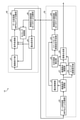
- FIG. 1 is a schematic block diagram of a VR head-mounted display system according to an embodiment.
- FIG. 1 illustrates an information processing device-connected VR head-mounted display system.
- the VR head-mounted display system 10 is roughly classified into a head-mounted display (hereinafter referred to as an HMD unit) 11 and an information processing device (hereinafter referred to as a PC unit) 12.
- the PC unit 12 functions as a control unit that controls the HMD unit 11.
- data is transferred between the HMD unit 11 and the PC unit 12 using the communication functions of each, it is omitted because it is not related to the explanation of the present technology.
- the HMD unit 11 includes an IMU (Inertial Measurement Unit) 21, a camera 22 for SLAM (Simultaneous Localization And Mapping), a VST (Video See-Through) camera 23, an eye tracking camera 24, and a display 25. There is.
- IMU Inertial Measurement Unit
- SLAM Simultaneous Localization And Mapping
- VST Video See-Through
- the IMU 21 is a so-called motion sensor, which senses the state of the user and outputs the sensing result to the PC unit 12.
- the IMU 21 has, for example, a 3-axis gyro sensor and a 3-axis acceleration sensor, and outputs user motion information (sensor information) corresponding to the detected three-dimensional angular velocity, acceleration, etc. to the PC unit 12.
- FIG. 2 is an explanatory diagram of a VR head-mounted display system showing an arrangement state of cameras.
- the SLAM camera 22 is a camera called SLAM for simultaneously performing self-position estimation and environment map creation, and acquiring an image to be used in a technique for obtaining a self-position from a state where there is no prior information such as map information. be.
- the SLAM camera is, for example, arranged in the central portion of the front surface of the HMD unit 11, and collects information for simultaneously performing self-position estimation and environmental map creation based on changes in the image in front of the HMD unit 11. .. SLAM will be described in detail later.
- the VST camera 23 acquires a VST image, which is an external image, and outputs the VST image to the PC unit 12.
- the VST camera 23 includes a lens installed outside the HMD unit 11 for VST and an image sensor 23A (see FIG. 3). As shown in FIG. 2, a pair of VST cameras 23 are provided so as to correspond to the positions of both eyes of the user.
- the imaging conditions (resolution, imaging area, imaging timing, etc.) of the VST camera 23 and eventually the image sensor are controlled by the PC unit 12.
- the image sensor 23A (see FIG. 3) constituting the VST camera 23 of the present embodiment has a high resolution but high processing load full resolution mode and a low resolution but processing load as operation modes. Has a low pixel addition mode. Then, the image sensor 23A can switch between the full resolution mode and the pixel addition mode on a frame-by-frame basis under the control of the PC unit 12.
- the pixel addition mode is one of the drive modes of the image sensor 23A, and the random noise for each pixel is stochastically reduced by the addition and averaging, so that the noise is reduced as compared with the full resolution mode. Fewer images will be obtained.
- 2 ⁇ 2 addition mode As an example of the pixel addition mode, 2 ⁇ 2 pixels (4 pixels in total) are added and averaged and output as 1 pixel, so that the resolution is 1/4 and the amount of noise is about 1. An image that is halved is output.
- 4x4 addition mode 4x4 pixels (16 pixels in total) are added and averaged and output as one pixel, so an image with a resolution of 1/16 and a noise amount of about 1/4 is output.
- the eye tracking camera 24 is a camera for tracking the user's line of sight, so-called eye tracking.
- the eye tracking camera 24 is configured as a non-visible light camera or the like.
- the eye tracking camera 24 is used, for example, to detect a user's area of interest required by a technique such as Variable Foveated Rendering. According to the recent eye tracking camera 24, the line-of-sight direction can be acquired with an accuracy of about ⁇ 0.5 °.
- the display 25 is a display device that displays a processed image of the PC unit 12.
- the PC unit 12 includes a self-position estimation unit 31, an attention area determination unit 32, an ISP (Image Signal Processor) 33, a motion compensation unit 34, a frame memory 35, and an image composition unit 36.
- ISP Image Signal Processor
- the self-position estimation unit 31 estimates the self-position including the posture of the user based on the sensor information output by the IMU 21 and the SLAM image acquired by the SLAM camera 22.
- the three-dimensional position of the HMD unit 11 is estimated using both the sensor information output by the IMU 21 and the SLAM image acquired by the SLAM camera 22.
- some methods such as VO (Visual Odometry) using only the camera image and VIO (Visual Inertial Odometry) using both the camera image and the output of IMU21 can be considered.
- the attention area determination unit 32 determines the user's attention area based on the eye tracking result image of both eyes, which is the output of the eye tracking camera 24, and outputs it to the ISP 33.
- the ISP 33 performs image processing on only the area of interest in the imaging area of the VST camera 23, or image processing on the entire area, based on the area of interest of the user determined by the area of interest 32.
- the ISP 33 processes the image signal output by the VST camera 23 and outputs it as a processed image signal. Specifically, as image signal processing, “noise removal”, “demosaic”, “white balance”, “exposure adjustment”, “contrast enhancement”, “gamma correction” and the like are performed. Due to the heavy processing load, mobile devices are often equipped with dedicated hardware.
- the motion compensation unit 34 performs motion compensation for the processed image signal and outputs the processed image signal based on the position of the HMD unit 11 estimated by the self-position estimation unit 31.
- the frame memory 35 stores the processed image signal after motion compensation in frame units.
- the resolution differs between the center and the periphery due to the influence of lens distortion.
- the recognition limit is about 20 ° for characters and about 60 ° for symbols around the visual axis. That is, it is known that the influence of blur has a spatial dependence centered on the line of sight of a person who is viewing an image as a user.
- the former is centered on the center of the screen, and the latter is centered on the visual axis, and the area close to the center is set as the area of interest. do. Then, for the region of interest, one second image captured at a predetermined exposure time in which blurring is unlikely to occur is acquired.
- one or more first images whose resolution is reduced (reduced by binning) and whose exposure is adjusted so that the entire imaging region is captured and the image quality is appropriate. To get.
- the first image obtained by binning has less noise than the image without binning.
- binning imaging (first image) is dynamic because the resolution is low but the S / N ratio is good because the exposure is controlled so that the exposure time is longer than the imaging of only the region of interest.
- S / N ratio is good because the exposure is controlled so that the exposure time is longer than the imaging of only the region of interest.
- the first image having a good S / N ratio and a high dynamic range and the second image having a high resolution and less blurring are combined to generate an image with improved image quality.
- an image in which blurring is suppressed at a high resolution is obtained in the region of interest, and an image having a low resolution but a good S / N ratio and a high dynamic range is obtained in areas other than the region of interest.
- the region of interest is displayed up to the display timing on the display. It is controlled so that the delay is minimized. Therefore, the region of interest can be displayed with low delay in the video see-through, and an image with a higher immersive feeling can be displayed.
- FIG. 3 is a functional block diagram of VST processing showing from the VST camera of the embodiment to image composition.
- the VST processing is roughly classified into an image sensor 40 and an image processing system 50.
- the image sensor 40 may be any as long as it can switch between binning imaging and cut-out imaging of the region of interest without a frame invalid period.
- the image sensor 40 is roughly classified into an image sensor unit 41, a signal processing unit 42, a data transmission unit 43, a timing control unit 44, an exposure setting unit 45, and a control setting communication unit 46.
- the image sensor unit 41 converts light into electric charges in the entire or specific area of the image pickup area and outputs it as an image pickup signal.
- the signal processing unit 42 performs binning processing, gain processing, or A / D conversion processing on the image pickup signal input from the image pickup element unit, and outputs it as image pickup data.
- the data transmission unit 43 outputs the image pickup data output by the signal processing unit to the image processing system.
- the timing control unit 44 generates and outputs the image pickup timing in the image pickup element unit or the timing of various signal processing in the signal processing unit.
- the exposure setting unit 45 sets an appropriate exposure for the image sensor unit or the signal processing unit.
- the control setting communication unit 46 mainly performs communication by I2C and outputs the control setting input from the image processing system to the timing control unit or the exposure setting unit.
- the binning process performed by the signal processing unit 42 will be described.
- the same colors are added and averaged by analog signals or digital data for the image sensor corresponding to each pixel constituting the image sensor unit.
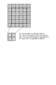
- FIG. 4 is an explanatory diagram of the binning process.
- the color filters are lined up, which is generally called a Bayer array, the same colors are added and averaged.
- a 4 ⁇ 4 pixel image is binned into a 2 ⁇ 2 pixel image.
- the addition may be weighted according to the position of the pixel.
- the value of the pixel R'after the binning process is expressed by, for example, the following equation using the values of the four pixels R1 to R4 before the binning process.
- R' (3 x R1 + R2 + 1.5 x R3 + 0.5 x R4) / 6
- the binning image corresponding to the first image is used as an image outside the region of interest.
- the image portion corresponding to the region of interest in the binning image is an image captured at an exposure time in which blurring is unlikely to occur in the region of interest (corresponding to the second image, hereinafter referred to as a blur reduction image). It is used for image composition. The details of image composition will be described later.
- the image processing system 50 is roughly classified into an exposure control unit 51, an attention area detection unit 52, an image sensor control setting creation unit 53, a control setting communication unit 54, a data reception unit 55, an image signal processing unit 56, and an image motion compensation unit. It includes 57, an image composition unit 58, and a binning image storage unit 59.
- the exposure control unit 51 controls the exposure of the image sensor.
- the attention area detection unit 52 detects the user's attention area in the captured image based on the line-of-sight information and the like.
- the image sensor control setting creation unit 53 calculates the control conditions to be set in the image sensor based on the exposure control information acquired from the exposure control unit and the detection result of the attention area detection unit.
- the control setting communication unit 54 mainly performs communication by I2C and sends the set control setting to the image sensor side.
- the data receiving unit 55 receives the image pickup data transmitted by the data transmitting unit of the image sensor.
- the image signal processing unit 56 develops the received image pickup data and outputs it to the image motion compensation unit 57 and the binning image storage unit 59.
- the binning image storage unit 59 stores the binning image for image composition and motion compensation, and outputs the binning image to the image motion compensation unit 57 or the image composition unit 58 as needed.
- the binning image storage unit 59 corresponds to the frame memory 35 in FIG.
- the image motion compensation unit 57 functions as a motion compensation unit 34, and displays an image to be imaged based on a processing delay from image capture to display display and motion information of an image object estimated from a plurality of captured images. Image motion compensation is performed by moving to the display position and performing motion compensation.
- a method of motion compensation executed by the image motion compensation unit 57 will be described.
- a motion compensation method a motion vector based on the image difference of the imaged object obtained by the optical flow algorithm such as the Lucas-Kanade method or the pixel value difference minimum search algorithm used in moving image compression is used. Then, based on the motion vector, the position where the image pickup object will be moving is estimated from the display display time to that time.
- the user's motion information obtained from the angular velocity output by the gyro sensor may be used as an auxiliary for motion compensation. This is effective in removing motion vectors that are presumed to be incorrect in the excursion area because they may be derived in the optical flow algorithm and the pixel value difference minimum search algorithm.
- the degree of similarity is calculated from the angle between the motion vector calculated from the angular acceleration output by the sensor and the motion vector. That is, it is said that the closer the directions of the two vectors are, the higher the similarity is, and the more different the directions of the two vectors are, the lower the similarity is.
- the motion vector based on the image difference that is different in excursion is replaced with the motion vector calculated from the gyro sensor, so that the motion is presumed to be incorrect.
- Vectors can be removed.
- FIG. 5 is an explanatory diagram of the removal of the motion vector presumed to be incorrect.
- the motion vector detection target TG1 to TG15 are composed of one pixel or a plurality of pixels.
- a motion vector is calculated by an optical flow algorithm, a pixel value difference minimum search algorithm, or the like based on the image difference.
- the motion vector calculated from the angular acceleration output by the gyro sensor is calculated. Then, for example, for the motion vector detection targets TG0 to TG4, TG6 to TG9, TG12, and TG13, the difference in direction (angle difference) between the motion vector based on the image difference and the motion vector calculated from each acceleration is small. Therefore, it is judged that the degree of similarity is high.
- the motion vector detection targets TG5, TG10, TG11, TG14, and TG15 have no similarity because the difference in direction (angle difference) between the motion vector based on the image difference and the motion vector calculated from each acceleration is large. Is judged.
- the motion vector detection target TG5 determines that the motion vector wrong in the excursion has been calculated.
- the motion vector for the motion vector detection target TG5 is set as the motion vector calculated from the angular acceleration output by the gyro sensor.
- the motion vector detection targets TG10, TG11, TG14, and TG15 have three or more dissimilar motion vectors among the motion vector detection targets around them, so that a motion different from their own motion is reflected. You can judge. If there is a motion vector calculated from the angular acceleration output by the gyro sensor in this way, the motion vector calculated incorrectly can be removed to obtain a motion vector that seems to be more correct.
- the image synthesizing unit 58 synthesizes the binning image and the image cut out in the region of interest with the image for which image signal processing and image motion compensation have been performed and the exposure conditions so as to maintain the contour of the region of interest. For the outer region, the binning image with image signal processing and motion compensation is output as it is.
- image composition will be described.
- the blur reduction image and the binning image whose exposure is adjusted so that the binning process and the image quality are appropriate are combined in the region of interest.
- the binning process effectively improves the S / N ratio and suppresses the use of digital gain, so that the combined image is effective as compared with the image obtained by reading out all pixels.
- the dynamic range is wide.
- FIG. 6 is a functional block diagram of the image composition unit.
- the image composition unit 58 is roughly classified into a high-pass filter processing unit 61, an image enlargement processing unit 62, a processing switching unit 63, an image addition unit 64, an attention area selection unit 65, an image switching unit 66, and a contour correction unit 67. There is.
- the high-pass filter processing unit 61 applies a high-frequency component for edge enhancement to the image in the region of interest, which is a motion-compensated blur-reducing image. Extract.
- the motion-compensated binning image is enlarged by the image enlargement processing unit 62 so as to have the same resolution as before the binning processing. Then, among the enlarged binning images, the image corresponding to the region of interest is output to the image addition unit 64 by the processing switching unit 63 under the control of the region of interest 65.
- the image addition unit 64 adds the blur reduction image output by the high-pass filter processing unit 61 and outputs it to the image switching unit 66. As a result, it is possible to maintain a high resolution in the region of interest and secure a large dynamic range.
- the image corresponding to the region other than the region of interest is directly output to the image switching unit 66 by the processing switching unit 63 under the control of the region of interest 65.
- the image switching unit 66 outputs any image data to the contour correction unit 67 based on whether the display target is an area of interest or an area other than the area of interest.
- the contour correction unit 67 outputs the input image with a sharper contour.
- images are combined so that the low-luminance region in the screen has a high blend ratio of long-exposure images (binning images BG1 and BG2 in the present embodiment), and the high-luminance region is short.
- the images are combined so that the blending ratio of the exposed image (blur-reduced image BL in the present embodiment) is high.
- range adjustment and bit expansion are performed on the enlarged binning image and the blurred binning image obtained by enlarging the binning image so that the resolution is the same as that of the blurred image. This is to match the luminance range and secure the band with the expansion of the dynamic range.
- an ⁇ map representing the luminance distribution in pixel units is generated for each of the enlarged binning image and the blur reduction image. Then, based on the luminance distribution corresponding to the generated ⁇ map, ⁇ blending is performed to synthesize the enlarged binning image and the blur reduction image.
- the low-brightness region pixels the image so that the blend ratio of the magnified binning image, which is a long-exposure image, is higher than the blend ratio of the blur-reduced image, which is a short-exposure image, based on the generated ⁇ -map. Synthesize in units.
- the image is pixel-by-pixel so that the blend ratio of the short-exposure image, the blur-reduced image, is higher than the blend ratio of the long-exposure image, the enlarged binning image, based on the generated ⁇ -map. Synthesize.
- the gradation correction is performed so that the gradation change becomes natural, that is, the gradation change becomes gentle. As a result, a natural, wide dynamic range, high-definition image can be obtained.
- FIG. 7 is an explanatory diagram of an example of the conventional imaging timing.
- the technique described in Patent Document 2 is shown, and the horizontal axis is time and the vertical axis is line.
- the widths of the camera exposure timings DS51 and DS52 represent the exposure time. Further, the widths of the display timings DP51 and DP52 represent the display update time. As shown in FIG. 7, the time required for one-line imaging by a camera and one-line display on a display is almost the same.
- the timing is adjusted so that the time for image processing and image data transfer to be performed until the camera images acquired by the camera exposure timings DS51 and DS52 are displayed on the display display timings DP51 and DP52 is minimized.
- the difference in position between the image pickup object included in the image captured by the VST camera 23 displayed on the display 25 and the actual image pickup object is minimized.
- the exposure time suitable for a high-resolution camera in an indoor illuminance environment of about 100 to 200 lux is often the exposure time at which blur occurs.
- FIG. 8 is an explanatory diagram of the imaging timing of the embodiment. Therefore, in the present embodiment, as shown in FIG. 8, although the resolution is lowered due to binning, one or more images are taken one or more times (twice in FIG. 8) in which the entire image pickup area is imaged. The acquisition of the binning images BG1 and BG2 (two images in FIG. 8) and the acquisition of one blur-reducing image BL by one imaging in which the imaging region is limited to the region of interest are alternately performed. There is.
- FIG. 8 as in FIG. 7, the horizontal axis is time and the vertical axis is line.
- the imaging timing of the binning image capable of low resolution but high SN ratio and high dynamic imaging due to binning that can be used as an image in an area other than the region of interest is set. It exists twice or once. More specifically, FIG. 8 shows a processing period of a frame capable of taking two images of the camera exposure timing DS1 and the camera exposure timing DS2.
- the imaged data that is closer in time to the display display timing is used for the actual display.
- each imaging timing of the blurred image BL which enables high-resolution imaging with an exposure time in which blurring is unlikely to occur, so that the image can be used as an image in the region of interest. More specifically, in FIG. 8, for example, the camera exposure timing DS3.
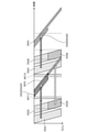
- FIG. 9 is an explanatory diagram of a more specific imaging timing of the embodiment.
- the horizontal axis is time and the vertical axis is line.
- the image pickup data group DG11 acquired by the camera exposure timing DS11 is used. Display.
- the image pickup data group DG12 acquired at the camera exposure timing DS12 is used for display.
- the image pickup data group DG15 acquired in the camera exposure timing DS13 corresponding to the attention area the image pickup data group DG13 acquired in the camera exposure timing DS11, and the camera exposure.
- the imaging data group of the three images corresponding to the imaging data group DG14 acquired corresponding to the timing DS14 is combined and displayed.
- the image is corrected so that the image quality of the captured image in the region of interest and the image quality outside the region of interest do not become uncomfortable, and then the composition is performed.
- the image pickup data group DG21 acquired in the camera exposure timing DS21 is used for display.
- the image pickup data group DG22 acquired in the camera exposure timing DS21 and the image pickup data group DG24 acquired in the camera exposure timing DS22 are supported. The two images are combined and displayed.
- the image correction is performed so that the image quality of the captured image in the region of interest and the image quality outside the region of interest do not become uncomfortable, and then the composition is performed. Then, when the display of the composite image corresponding to the region of interest is completed, the display is performed by the image pickup data group DG23 acquired in the camera exposure timing DS21.
- the timing of capturing the blur-reduced image which is the second image
- the timing of capturing the binning image which is the first image.
- the area can be displayed with higher real-time property, and the image with a high immersive feeling can be displayed by suppressing the deviation between the position of the actual imaged object and the position of the imaged object in the composite image.
- an adjustment margin period is provided to cope with the change of the region of interest (movement of the region of interest) during the processing of one frame.
- the adjustment margin periods INT11 and INT12 are provided between the camera exposure timing DS11 and the camera exposure timing DS21 corresponding to one frame of the blur reduction image and the camera exposure timing DS12 and DS21 before and after the camera exposure timing DS11.
- FIG. 10 is another explanatory diagram of the imaging timing of the embodiment.
- FIG. 10 shows a case where the region of interest is changed to the upper side of the imaging region as compared with the case of FIG.
- the horizontal axis is time and the vertical axis is line.
- a binning image that can be used as an image in a region other than the region of interest has a low resolution but a high S / N ratio and high dynamic imaging.
- the point that the timing exists twice is the same, but the point that the region of interest is above the imaging region is different.
- the imaging data group acquired in the camera exposure timing DS31 and the camera exposure timing DS32 are acquired.
- the image pickup data group and the image pickup data group DG33 acquired in the camera exposure timing DS33 are combined and displayed.
- the display is performed by the image pickup data group DG32 acquired in the camera exposure timing DS32.
- the image pickup data group DG43 acquired in the camera exposure timing DS43 corresponding to the attention area the image pickup data group acquired in the camera exposure timing DS41, and the camera exposure timing.
- Imaging data group acquired corresponding to DS42 The imaging data group of three images corresponding to DG42 is combined and displayed.
- the image correction is performed so that the image quality of the captured image in the region of interest and the image quality outside the region of interest do not become uncomfortable, and then the composition is performed.
- the region of interest is changed, only the processing start timing is changed, and the processing content is always the same, so that the image can be reliably displayed.
- FIG. 11 is a processing flowchart for controlling the imaging timing of the camera.
- the fact that the previous focus area is different from the focus area currently being imaged does not mean that the physical coincidence is not the case, and the user's line of sight can be recognized as being changed. Refers to the case where it is different.
- step S11 if the previous area of interest is the same as the area of interest currently being imaged (step S11; No), the process proceeds to step S20.
- step S11 if the region of interest is different from the region currently being photographed (step S11; Yes), it is determined whether the next imaging mode is different from the current imaging mode (step S12).
- the mode is either a mode in which imaging is performed by binning processing or a mode in which imaging is performed only in the region of interest.
- step S12 if the next imaging mode is different from the current imaging mode (step S12; Yes), it is determined whether or not the region of interest has moved upward (step S13). In the determination of step S13, when the region of interest moves upward (step S13; Yes), the timing is changed in the direction of advancing the image pickup timing of the camera in the timing setting (step S14).
- step S15 it is determined whether or not the changed setting exceeds the change upper limit in the direction of accelerating the timing determined by the adjustment margin period (adjustment margin period INT11, INT12 in the present embodiment) (step S15). That is, it is determined whether or not the change upper limit falls within the adjustment margin period.
- step S15 if the changed setting exceeds the change upper limit determined by the adjustment margin (step S15; Yes), the change upper limit is set in the direction of accelerating the changed setting, and the process ends (step S16). .. In the determination of step S15, if the changed setting does not exceed the change upper limit in the direction of accelerating the setting determined by the adjustment margin (step S15; No), the changed setting is valid and the process ends.
- step S13 if the region of interest has not moved upward (step S13; No), the timing is set in the direction of delaying the timing in the timing setting (step S17). Then, it is determined whether or not the changed setting exceeds the change upper limit of the one that delays the setting determined by the adjustment margin (step S18).
- step S18 if the changed setting exceeds the change upper limit in the slowing direction determined by the adjustment margin (step S18; Yes), the process ends as the change upper limit in the slowing direction after the change. (Step S19). In the determination of step S18, if the changed setting does not exceed the change upper limit in the direction of delaying the setting determined by the adjustment margin (step S19; No), the changed setting is valid and the process ends.
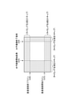
- FIG. 12 is an explanatory diagram of processing at the time of acquiring a blur reduction image.
- the processing at the time of acquiring the blur reduction image has not been described in detail, but when acquiring the blur reduction image in the region of interest, the procedure is as follows.
- the image processing system 50 sets the horizontal image pickup start pixel GHS and the flat image pickup end pixel GHE, the vertical image pickup start line GVS, and the vertical image pickup end line GVE for the timing control unit 44. Then, during the imaging operation, it is realized by skipping the generation of the imaging timing outside the region of interest.
- the image is not output for the skipped portion, it is possible to acquire the image of only the required region of interest and finish the image data transfer as soon as the skipped portion in the vertical direction. ing.
- one blur-reducing image is captured for one or two binning images and combined, but one or two blur-reducing images are captured. It is possible to obtain the same effect by capturing a plurality of binning images and synthesizing them.
- the present technology can be configured as follows. (1) The first image input from the image sensor and captured in the first exposure time and the image corresponding to a part of the area of the first image in the second exposure time shorter than the first exposure time. In generating a composite image that is a composite of the second image to be captured, A control unit is provided that sets the imaging timing of the second image closer to the timing of outputting the composite image to the display device than the imaging timing of the first image. Image processing device. (2) The resolution of the first image is defined as the first resolution. The resolution of the second image is set to a second resolution higher than the first resolution. The image processing apparatus according to (1). (3) The predetermined area of interest is displayed by the composite image, and is displayed. Areas other than the area of interest are displayed based on the first image.
- the image processing apparatus according to (1) or (2).
- the first image a plurality of images having different camera exposure timings are acquired and held.
- one of a plurality of the first images has a relatively short time from the camera exposure timing to the timing of output to the display device. Display using the first image.
- the image processing apparatus according to (3).
- the control unit sets a timing adjustment margin for absorbing fluctuations in the imaging timing due to a change in the region of interest before and after the imaging timing of the second image.
- the imaging timing of the first image is set at a timing other than the timing adjustment margin and the imaging timing of the second image.
- the image processing apparatus according to (3) or (4).
- the first image is a binning image and is The second image is a blur reduction image in which the second exposure time is set for the purpose of blur reduction.
- the image processing apparatus according to any one of (1) to (5).
- the control unit generates the composite image and outputs the composite image to the display device in real time.
- the image processing apparatus according to any one of (1) to (6).
- a second image having an image sensor and having a first resolution captured in the first exposure time and an image corresponding to a part of the region of the first image, which is shorter than the first exposure time.
- An image pickup device that is imaged at an exposure time and outputs a second image having a second resolution higher than the first resolution.
- An image processing device provided with a control unit that generates and outputs a composite image obtained by synthesizing the first image and the second image.
- a display device that displays the input composite image and Image display system with.
- the image pickup device is attached to the user and is attached to the user.
- the image display system includes a line-of-sight direction detection device that detects the line-of-sight direction of the user. The area of interest is set based on the line-of-sight direction.
- the image display system according to (8).
- a program for controlling an image processing device that controls an image sensor by a computer The computer A first image captured in the first exposure time and an image corresponding to a part of the region of the first image and captured in a second exposure time shorter than the first exposure time.
- VR head-mounted display system image display system
- HMD section Head-mounted display
- Information processing device PC section
- IMU SLAM camera 23
- VST camera 23A image sensor 24
- eye tracking camera 25
- display 31
- self-position estimation unit 32
- ISP 34 Compensation unit 35
- Frame memory 36
- Image composition unit 10
Landscapes
- Engineering & Computer Science (AREA)
- Multimedia (AREA)
- Signal Processing (AREA)
- Theoretical Computer Science (AREA)
- Physics & Mathematics (AREA)
- General Physics & Mathematics (AREA)
- General Engineering & Computer Science (AREA)
- Computer Hardware Design (AREA)
- Human Computer Interaction (AREA)
- Computer Graphics (AREA)
- Software Systems (AREA)
- Optics & Photonics (AREA)
- Studio Devices (AREA)
Abstract
According to the embodiments, the image processing device comprises a control unit that generates a composite image and outputs the composite image to a display device, the composite image being synthesized from a first image that is inputted from an image sensor, is captured over a first exposure time, and has a first resolution and a second image that corresponds to a partial region of the first image, is captured over a second exposure time that is shorter than the first exposure time, and has a second resolution that is higher than the first resolution.
Description
本開示は、画像処理装置、画像表示システム、方法及びプログラムに関する。
This disclosure relates to an image processing device, an image display system, a method and a program.
従来、主としてVST(Video See-Through)システムに用いられることを想定し、アイトラッキングシステムにより推定した視線位置により注目領域を算出し、撮影後に非注目領域のみ画像を間引く処理(解像度変換処理)を施し、画像処理にかかる処理負荷を低減できる技術が提案されている。
Conventionally, assuming that it is mainly used for VST (Video See-Through) systems, the attention area is calculated from the line-of-sight position estimated by the eye tracking system, and the image is thinned out only in the non-attention area after shooting (resolution conversion processing). A technique has been proposed that can reduce the processing load required for image processing.
特許文献1記載の技術においては、注目領域と非注目領域で異なる解像度での撮像を行い、注目領域以外の解像度を落とすことで処理負荷を下げている。
In the technique described in Patent Document 1, imaging is performed at different resolutions in the attention region and the non-attention region, and the processing load is reduced by lowering the resolution other than the attention region.
特許文献2記載の技術においては、カメラ撮像タイミングとディスプレイ表示タイミングを最適化することでビデオシースルーの低遅延を実現している。
In the technology described in Patent Document 2, low delay of video see-through is realized by optimizing the camera imaging timing and the display display timing.
ところで、VSTシステムにおいて、現実と遜色のない表示を実現するには高精細なカメラが必要不可欠である。しかしながら、高精細を実現すべく、画素が細かくなるほど露出条件を維持するために露光時間が長くなり、露光中の動きによってブラー(いわゆる撮像ボケ)が発生し、現実との齟齬を感じたりVR酔いや疲労感の増大を招くこととなっていた。
By the way, in the VST system, a high-definition camera is indispensable to realize a display comparable to reality. However, in order to achieve high definition, the finer the pixels, the longer the exposure time to maintain the exposure conditions, and the movement during exposure causes blurring (so-called image blurring), which causes a discrepancy with reality and VR sickness. It was supposed to cause an increase in feeling of fatigue.
また入力となるカメラから出力となるディスプレイまでの処理遅延、データ転送遅延が現実とディスプレイ表示の位置乖離を生じさせる。この位置乖離もまたVR酔いや疲労感の増大を招く要因となっている。このため、位置乖離を回避するために動き予測を用いるが、システム内の遅延が大きければ大きいほど予測外れ確率が上がるため、システムパスは低遅延で設計することが重要となっていた。
In addition, the processing delay from the input camera to the output display and the data transfer delay cause a positional gap between the reality and the display display. This positional deviation is also a factor that causes an increase in VR sickness and a feeling of fatigue. For this reason, motion prediction is used to avoid positional deviation, but it has been important to design the system path with low delay because the larger the delay in the system, the higher the probability of misprediction.
さらにビデオシースルー映像を人が目で直接見ているようにディスプレイに表示するためには、高画質及び低遅延の両立が望まれる。
Furthermore, in order to display the video see-through image on the display as if the person is looking directly at it, it is desired to achieve both high image quality and low delay.
本技術は、このような状況に鑑みてなされたものであり、画像処理にかかる処理負荷を低減しつつ、低遅延で、ブラーの削減及び高精細化を実現することが可能な画像処理装置、画像表示システム、方法及びプログラムを提供することを目的としている。
This technology was made in view of such a situation, and is an image processing device that can realize reduction of blur and high definition with low delay while reducing the processing load on image processing. It is intended to provide image display systems, methods and programs.
実施形態の画像処理装置は、イメージセンサから入力された、第1露光時間で撮像される第1画像と、前記第1画像の一部の領域に相当する画像であって、前記第1露光時間よりも短い第2露光時間で撮像される第2画像とを合成した合成画像を生成するに際し、前記第2画像の撮像タイミングを、前記第1画像の撮像タイミングよりも、前記合成画像を表示装置に出力するタイミングにより近いタイミングとする制御部を備える。
The image processing apparatus of the embodiment is a first image input from an image sensor and captured in the first exposure time, and an image corresponding to a part of the region of the first image, and the first exposure time. When generating a composite image in which a second image captured with a shorter second exposure time is combined, the image pickup timing of the second image is set to a display device for displaying the composite image rather than the capture timing of the first image. It is provided with a control unit whose timing is closer to the timing of output to.
以下、図面を参照して、実施形態について詳細に説明する。
図1は、実施形態のVRヘッドマウントディスプレイシステムの概要構成ブロック図である。
図1においては、情報処理装置接続型のVRヘッドマウントディスプレイシステムを例示している。 Hereinafter, embodiments will be described in detail with reference to the drawings.
FIG. 1 is a schematic block diagram of a VR head-mounted display system according to an embodiment.
FIG. 1 illustrates an information processing device-connected VR head-mounted display system.
VRヘッドマウントディスプレイシステム10は、大別すると、ヘッドマウントディスプレイ(以下、HMD部という)11と、情報処理装置(以下、PC部という)12と、を備えている。
ここで、PC部12は、HMD部11を制御する制御部として機能している。またHMD部11とPC部12の間はそれぞれが持つ通信機能を用いてデータを転送しているが本技術の説明に関わらないので省略している。 The VR head-mounteddisplay system 10 is roughly classified into a head-mounted display (hereinafter referred to as an HMD unit) 11 and an information processing device (hereinafter referred to as a PC unit) 12.
Here, thePC unit 12 functions as a control unit that controls the HMD unit 11. Further, although data is transferred between the HMD unit 11 and the PC unit 12 using the communication functions of each, it is omitted because it is not related to the explanation of the present technology.
ここで、PC部12は、HMD部11を制御する制御部として機能している。またHMD部11とPC部12の間はそれぞれが持つ通信機能を用いてデータを転送しているが本技術の説明に関わらないので省略している。 The VR head-mounted
Here, the
HMD部11は、IMU(Inertial Measurement Unit)21と、SLAM(Simultaneous Localization And Mapping)用カメラ22と、VST(Video See-Through)カメラ23と、アイトラッキングカメラ24と、ディスプレイ25と、を備えている。
The HMD unit 11 includes an IMU (Inertial Measurement Unit) 21, a camera 22 for SLAM (Simultaneous Localization And Mapping), a VST (Video See-Through) camera 23, an eye tracking camera 24, and a display 25. There is.
IMU21は、いわゆるモーションセンサであり、ユーザの状態等をセンシングし、センシング結果をPC部12に出力する。
IMU21は、例えば、3軸ジャイロセンサおよび3軸加速度センサを有し、検出した3次元の角速度、加速度等に対応するユーザの動き情報(センサ情報)をPC部12に出力する。 The IMU 21 is a so-called motion sensor, which senses the state of the user and outputs the sensing result to thePC unit 12.
TheIMU 21 has, for example, a 3-axis gyro sensor and a 3-axis acceleration sensor, and outputs user motion information (sensor information) corresponding to the detected three-dimensional angular velocity, acceleration, etc. to the PC unit 12.
IMU21は、例えば、3軸ジャイロセンサおよび3軸加速度センサを有し、検出した3次元の角速度、加速度等に対応するユーザの動き情報(センサ情報)をPC部12に出力する。 The IMU 21 is a so-called motion sensor, which senses the state of the user and outputs the sensing result to the
The
図2は、カメラの配置状態を表すVRヘッドマウントディスプレイシステムの説明図である。
SLAM用カメラ22は、SLAMと称される自己位置推定と環境地図作成とを同時に行い、地図情報などの事前情報がない状態から自己位置を求める技術に用いるための画像を取得するためのカメラである。SLAM用カメラは、例えば、HMD部11の前面の中央部に配置されており、HMD部11の前方の画像の変化に基づいて自己位置推定と環境地図作成とを同時に行うための情報収集を行う。SLAMについては、後に詳述する。 FIG. 2 is an explanatory diagram of a VR head-mounted display system showing an arrangement state of cameras.
TheSLAM camera 22 is a camera called SLAM for simultaneously performing self-position estimation and environment map creation, and acquiring an image to be used in a technique for obtaining a self-position from a state where there is no prior information such as map information. be. The SLAM camera is, for example, arranged in the central portion of the front surface of the HMD unit 11, and collects information for simultaneously performing self-position estimation and environmental map creation based on changes in the image in front of the HMD unit 11. .. SLAM will be described in detail later.
SLAM用カメラ22は、SLAMと称される自己位置推定と環境地図作成とを同時に行い、地図情報などの事前情報がない状態から自己位置を求める技術に用いるための画像を取得するためのカメラである。SLAM用カメラは、例えば、HMD部11の前面の中央部に配置されており、HMD部11の前方の画像の変化に基づいて自己位置推定と環境地図作成とを同時に行うための情報収集を行う。SLAMについては、後に詳述する。 FIG. 2 is an explanatory diagram of a VR head-mounted display system showing an arrangement state of cameras.
The
VSTカメラ23は、外部画像であるVST画像を取得してPC部12に出力する。
VSTカメラ23は、VST用にHMD部11外側に設置されたレンズとイメージセンサ23A(図3参照)と、を備えている。VSTカメラ23は、図2に示すように、ユーザの両目の位置に対応するように一対設けられている。 TheVST camera 23 acquires a VST image, which is an external image, and outputs the VST image to the PC unit 12.
TheVST camera 23 includes a lens installed outside the HMD unit 11 for VST and an image sensor 23A (see FIG. 3). As shown in FIG. 2, a pair of VST cameras 23 are provided so as to correspond to the positions of both eyes of the user.
VSTカメラ23は、VST用にHMD部11外側に設置されたレンズとイメージセンサ23A(図3参照)と、を備えている。VSTカメラ23は、図2に示すように、ユーザの両目の位置に対応するように一対設けられている。 The
The
この場合において、VSTカメラ23、ひいては、イメージセンサの撮像条件(解像度、撮像領域、撮像タイミング等)は、PC部12により制御されている。
In this case, the imaging conditions (resolution, imaging area, imaging timing, etc.) of the VST camera 23 and eventually the image sensor are controlled by the PC unit 12.
本実施形態のVSTカメラ23を構成しているイメージセンサ23A(図3参照)は、動作モードとして、高解像度であるが処理負荷の高いフル(Full)解像度モードと、低解像度であるが処理負荷の低い画素加算モードと、を有している。
そして、イメージセンサ23Aは、PC部12の制御下で、フル解像モードと、画素加算モードと、をフレーム単位で切り替えることができる。 The image sensor 23A (see FIG. 3) constituting theVST camera 23 of the present embodiment has a high resolution but high processing load full resolution mode and a low resolution but processing load as operation modes. Has a low pixel addition mode.
Then, the image sensor 23A can switch between the full resolution mode and the pixel addition mode on a frame-by-frame basis under the control of thePC unit 12.
そして、イメージセンサ23Aは、PC部12の制御下で、フル解像モードと、画素加算モードと、をフレーム単位で切り替えることができる。 The image sensor 23A (see FIG. 3) constituting the
Then, the image sensor 23A can switch between the full resolution mode and the pixel addition mode on a frame-by-frame basis under the control of the
この場合において、画素加算モードは、イメージセンサ23Aの駆動モードの一つであり、画素ごとのランダム性ノイズが加算平均されることにより確率的に減少するため、フル解像度モードに比較してノイズが少ない画像が得られることとなる。
In this case, the pixel addition mode is one of the drive modes of the image sensor 23A, and the random noise for each pixel is stochastically reduced by the addition and averaging, so that the noise is reduced as compared with the full resolution mode. Fewer images will be obtained.
具体的には、画素加算モードの一例としての2×2加算モードでは縦横2×2画素(全4画素)を加算平均して1画素として出力するため、解像度が1/4、ノイズ量が約1/2となった画像が出力される。同様に4×4加算モードでは縦横4×4画素(全16画素)を加算平均して1画素として出力するため、解像度が1/16、ノイズ量が約1/4となった画像が出力される。
Specifically, in the 2 × 2 addition mode as an example of the pixel addition mode, 2 × 2 pixels (4 pixels in total) are added and averaged and output as 1 pixel, so that the resolution is 1/4 and the amount of noise is about 1. An image that is halved is output. Similarly, in the 4x4 addition mode, 4x4 pixels (16 pixels in total) are added and averaged and output as one pixel, so an image with a resolution of 1/16 and a noise amount of about 1/4 is output. To.
アイトラッキングカメラ24は、ユーザの視線を追跡、いわゆるアイトラッキング(eye tracking)を行うためのカメラである。アイトラッキングカメラ24は、可視光外カメラ等として構成されている。
The eye tracking camera 24 is a camera for tracking the user's line of sight, so-called eye tracking. The eye tracking camera 24 is configured as a non-visible light camera or the like.
アイトラッキングカメラ24は、例えば、Variable Foveated Rendering等の手法で必要なユーザの注目領域を検出するために用いられる。近年のアイトラッキングカメラ24によれば、±0.5°程度の精度で視線方向が取得できる。
ディスプレイ25は、PC部12の処理後の画像を表示する表示装置である。 Theeye tracking camera 24 is used, for example, to detect a user's area of interest required by a technique such as Variable Foveated Rendering. According to the recent eye tracking camera 24, the line-of-sight direction can be acquired with an accuracy of about ± 0.5 °.
The display 25 is a display device that displays a processed image of thePC unit 12.
ディスプレイ25は、PC部12の処理後の画像を表示する表示装置である。 The
The display 25 is a display device that displays a processed image of the
PC部12は、自己位置推定部31と、注目領域決定部32と、ISP(Image Signal Processor)33と、動き補償部34と、フレームメモリ35と、画像合成部36と、を備えている。
The PC unit 12 includes a self-position estimation unit 31, an attention area determination unit 32, an ISP (Image Signal Processor) 33, a motion compensation unit 34, a frame memory 35, and an image composition unit 36.
自己位置推定部31は、IMU21が出力したセンサ情報及びSLAM用カメラ22が取得したSLAM用画像に基づいてユーザの姿勢等を含む自己位置を推定する。
The self-position estimation unit 31 estimates the self-position including the posture of the user based on the sensor information output by the IMU 21 and the SLAM image acquired by the SLAM camera 22.
本実施形態においては、自己位置推定部31の自己位置推定の手法として、IMU21が出力したセンサ情報及びSLAM用カメラ22が取得したSLAM用画像の双方を用いてHMD部11の3次元位置を推定する手法を用いているが、カメラ画像のみを用いるVO(Visual Odometry)、カメラ画像及びIMU21の出力の両方を用いるVIO(Visual Inertial Odometry)等、いくつかの手法が考えられる。
In the present embodiment, as a method of self-position estimation of the self-position estimation unit 31, the three-dimensional position of the HMD unit 11 is estimated using both the sensor information output by the IMU 21 and the SLAM image acquired by the SLAM camera 22. However, some methods such as VO (Visual Odometry) using only the camera image and VIO (Visual Inertial Odometry) using both the camera image and the output of IMU21 can be considered.
注目領域決定部32は、アイトラッキングカメラ24の出力である両眼のアイトラッキング結果像に基づいて、ユーザの注目領域を決定して、ISP33に出力する。
ISP33は、注目領域決定部32が決定したユーザの注目領域に基づいて、VSTカメラ23の撮像領域における注目領域のみを画像処理したり、または全体領域を画像処理したりする。 The attentionarea determination unit 32 determines the user's attention area based on the eye tracking result image of both eyes, which is the output of the eye tracking camera 24, and outputs it to the ISP 33.
TheISP 33 performs image processing on only the area of interest in the imaging area of the VST camera 23, or image processing on the entire area, based on the area of interest of the user determined by the area of interest 32.
ISP33は、注目領域決定部32が決定したユーザの注目領域に基づいて、VSTカメラ23の撮像領域における注目領域のみを画像処理したり、または全体領域を画像処理したりする。 The attention
The
また、ISP33は、VSTカメラ23の出力した画像信号の処理を行って処理済画像信号として出力する。具体的には、画像信号の処理としては、「ノイズ除去」、「デモザイク」、「ホワイトバランス」、「露出調整」、「コントラスト強調」、「ガンマ補正」等を行う。処理負荷が大きいため、モバイル機器では、基本的に専用のハードウェアが用意されていることが多い。
Further, the ISP 33 processes the image signal output by the VST camera 23 and outputs it as a processed image signal. Specifically, as image signal processing, "noise removal", "demosaic", "white balance", "exposure adjustment", "contrast enhancement", "gamma correction" and the like are performed. Due to the heavy processing load, mobile devices are often equipped with dedicated hardware.
動き補償部34は、自己位置推定部31の推定したHMD部11の位置に基づいて、処理済画像信号の動き補償を行って出力する。
フレームメモリ35は、動き補償後の処理済み画像信号をフレーム単位で記憶する。 Themotion compensation unit 34 performs motion compensation for the processed image signal and outputs the processed image signal based on the position of the HMD unit 11 estimated by the self-position estimation unit 31.
Theframe memory 35 stores the processed image signal after motion compensation in frame units.
フレームメモリ35は、動き補償後の処理済み画像信号をフレーム単位で記憶する。 The
The
まず、実施形態の詳細な動作説明に先立ち、実施形態の原理を説明する。
VSTカメラ23として、高解像度かつ広角のカメラを用いた場合には、レンズ歪の影響で中央と周辺で解像感が異なる。 First, the principle of the embodiment will be described prior to the detailed operation explanation of the embodiment.
When a high-resolution and wide-angle camera is used as theVST camera 23, the resolution differs between the center and the periphery due to the influence of lens distortion.
VSTカメラ23として、高解像度かつ広角のカメラを用いた場合には、レンズ歪の影響で中央と周辺で解像感が異なる。 First, the principle of the embodiment will be described prior to the detailed operation explanation of the embodiment.
When a high-resolution and wide-angle camera is used as the
また、ブラーが気になるほど画像に注目する場合には、視軸を中心に文字で20°程度、シンボルで60°程度が認識限界であることが知られている。すなわち、ブラーの影響には、ユーザである画像を見ている人の視線を中心にした空間依存性があることが知られている。
It is also known that when paying attention to an image to the extent that blurring is anxious, the recognition limit is about 20 ° for characters and about 60 ° for symbols around the visual axis. That is, it is known that the influence of blur has a spatial dependence centered on the line of sight of a person who is viewing an image as a user.
そこで、VSTカメラ23の解像感あるいは人の視線を中心にした空間依存性を利用し、前者では画面の中央を中心に、後者では視軸を中心にして、中心に近い領域を注目領域とする。
そして、注目領域については、ブラーの起きにくい所定の露光時間で撮像した一つの第2画像を取得する。 Therefore, by utilizing the resolution of theVST camera 23 or the spatial dependence centered on the line of sight of a person, the former is centered on the center of the screen, and the latter is centered on the visual axis, and the area close to the center is set as the area of interest. do.
Then, for the region of interest, one second image captured at a predetermined exposure time in which blurring is unlikely to occur is acquired.
そして、注目領域については、ブラーの起きにくい所定の露光時間で撮像した一つの第2画像を取得する。 Therefore, by utilizing the resolution of the
Then, for the region of interest, one second image captured at a predetermined exposure time in which blurring is unlikely to occur is acquired.
一方、注目領域以外の領域については、解像度を低下し(ビニング[Binning]によって縮小)、かつ、撮像領域全体をとらえて画質が適切になるように露出を調整した一つ又は複数の第1画像を取得する。
On the other hand, for areas other than the region of interest, one or more first images whose resolution is reduced (reduced by binning) and whose exposure is adjusted so that the entire imaging region is captured and the image quality is appropriate. To get.
ビニングによって得られた第1画像は、ビニング無しの画像にくらべノイズが減っている。またビニング撮像(第1画像)は注目領域のみの撮像よりも露光時間が長くなるように露光制御することでその分デジタルゲインを用いずに済むため、解像度は低いがS/N比が良くダイナミックレンジの高い画像が得られやすいというメリットもある。
The first image obtained by binning has less noise than the image without binning. In addition, binning imaging (first image) is dynamic because the resolution is low but the S / N ratio is good because the exposure is controlled so that the exposure time is longer than the imaging of only the region of interest. There is also the advantage that it is easy to obtain images with a high range.
そして、注目領域においてはS/N比が良くダイナミックレンジの高い第1画像と解像度が高くブラーの起きにくい第2画像を合成することで、画質を改善した画像を生成する。
これらの結果、本実施形態によれば、注目領域については、高解像度でブラーの発生が抑制された画像が、注目領域以外については、解像度は低いがS/N比が良くダイナミックレンジの高い画像がVST画像としてディスプレイに表示される。
さらに、本実施形態においては、注目領域の撮影(第2画像の撮影)をディスプレイにおける表示タイミングと合わせるようにタイミングを調整、または、撮像順番を入れ替えることで、注目領域についてディスプレイにおける表示タイミングまでの遅延が最小となるように制御している。
したがって、注目領域については、ビデオシースルーにおいて低遅延で表示を行うことができ、より没入感の高い画像を表示することができる。 Then, in the region of interest, the first image having a good S / N ratio and a high dynamic range and the second image having a high resolution and less blurring are combined to generate an image with improved image quality.
As a result, according to the present embodiment, an image in which blurring is suppressed at a high resolution is obtained in the region of interest, and an image having a low resolution but a good S / N ratio and a high dynamic range is obtained in areas other than the region of interest. Is displayed on the display as a VST image.
Further, in the present embodiment, by adjusting the timing so that the shooting of the region of interest (shooting of the second image) matches the display timing on the display, or by changing the imaging order, the region of interest is displayed up to the display timing on the display. It is controlled so that the delay is minimized.
Therefore, the region of interest can be displayed with low delay in the video see-through, and an image with a higher immersive feeling can be displayed.
次に実施形態の機能ブロック図について説明する。
図3は、実施形態のVSTカメラから画像合成までを表したVST処理の機能ブロック図である。
VST処理は、大別すると、イメージセンサ40及び画像処理システム50を備えている。
イメージセンサ40は、ビニング撮像と注目領域の切り出し撮像がフレーム無効期間なく切替できるものであればよい。 Next, the functional block diagram of the embodiment will be described.
FIG. 3 is a functional block diagram of VST processing showing from the VST camera of the embodiment to image composition.
The VST processing is roughly classified into animage sensor 40 and an image processing system 50.
Theimage sensor 40 may be any as long as it can switch between binning imaging and cut-out imaging of the region of interest without a frame invalid period.
図3は、実施形態のVSTカメラから画像合成までを表したVST処理の機能ブロック図である。
VST処理は、大別すると、イメージセンサ40及び画像処理システム50を備えている。
イメージセンサ40は、ビニング撮像と注目領域の切り出し撮像がフレーム無効期間なく切替できるものであればよい。 Next, the functional block diagram of the embodiment will be described.
FIG. 3 is a functional block diagram of VST processing showing from the VST camera of the embodiment to image composition.
The VST processing is roughly classified into an
The
イメージセンサ40は、大別すると、撮像素子部41、信号処理部42、データ送信部43、タイミング制御部44、露出設定部45及び制御設定通信部46を備えている。
撮像素子部41は、撮像領域のうち、全部または特定領域を指定された範囲において光を電荷に変換して撮像信号として出力する。 Theimage sensor 40 is roughly classified into an image sensor unit 41, a signal processing unit 42, a data transmission unit 43, a timing control unit 44, an exposure setting unit 45, and a control setting communication unit 46.
The image sensor unit 41 converts light into electric charges in the entire or specific area of the image pickup area and outputs it as an image pickup signal.
撮像素子部41は、撮像領域のうち、全部または特定領域を指定された範囲において光を電荷に変換して撮像信号として出力する。 The
The image sensor unit 41 converts light into electric charges in the entire or specific area of the image pickup area and outputs it as an image pickup signal.
信号処理部42は、撮像素子部から入力された撮像信号に対してビニング処理、ゲイン処理あるいはA/D変換処理を行い撮像データとして出力する。
データ送信部43は、信号処理部が出力した撮像データを画像処理システムに出力する。 Thesignal processing unit 42 performs binning processing, gain processing, or A / D conversion processing on the image pickup signal input from the image pickup element unit, and outputs it as image pickup data.
Thedata transmission unit 43 outputs the image pickup data output by the signal processing unit to the image processing system.
データ送信部43は、信号処理部が出力した撮像データを画像処理システムに出力する。 The
The
タイミング制御部44は、撮像素子部における撮像タイミングあるいは信号処理部における各種信号処理のタイミングを生成し出力する。
露出設定部45は、撮像素子部あるいは信号処理部に対して適切な露出を設定する。
制御設定通信部46は、主としてI2Cによる通信を行ってタイミング制御部あるいは露出設定部に対し、画像処理システムから入力された制御設定を出力する。 The timing control unit 44 generates and outputs the image pickup timing in the image pickup element unit or the timing of various signal processing in the signal processing unit.
The exposure setting unit 45 sets an appropriate exposure for the image sensor unit or the signal processing unit.
The control setting communication unit 46 mainly performs communication by I2C and outputs the control setting input from the image processing system to the timing control unit or the exposure setting unit.
ここで、信号処理部42で行うビニング処理について説明する。
ビニング処理は、撮像素子部を構成している各画素に相当する撮像素子に対して同じ色同士をアナログ信号あるいはデジタルデータにより加算平均を行う。 Here, the binning process performed by thesignal processing unit 42 will be described.
In the binning process, the same colors are added and averaged by analog signals or digital data for the image sensor corresponding to each pixel constituting the image sensor unit.
ビニング処理は、撮像素子部を構成している各画素に相当する撮像素子に対して同じ色同士をアナログ信号あるいはデジタルデータにより加算平均を行う。 Here, the binning process performed by the
In the binning process, the same colors are added and averaged by analog signals or digital data for the image sensor corresponding to each pixel constituting the image sensor unit.
図4は、ビニング処理の説明図である。
一般にベイヤ配列と呼ばれる並びにカラーフィルタが並んでいるときに同じ色同士を加算平均する。
図4の例においては、4×4画素の画像を2×2画素の画像にビニング処理を行った場合である。 FIG. 4 is an explanatory diagram of the binning process.
When the color filters are lined up, which is generally called a Bayer array, the same colors are added and averaged.
In the example of FIG. 4, a 4 × 4 pixel image is binned into a 2 × 2 pixel image.
この場合において、図4に示すように、画素の位置にしたがって加算の重みづけを行ってもよい。
具体的には、ビニング処理後の画素R’の値は、ビニング処理前の四つの画素R1~R4の値を用いて、例えば、次式のように表される。
R’=(3×R1+R2+1.5×R3+0.5×R4)/6 In this case, as shown in FIG. 4, the addition may be weighted according to the position of the pixel.
Specifically, the value of the pixel R'after the binning process is expressed by, for example, the following equation using the values of the four pixels R1 to R4 before the binning process.
R'= (3 x R1 + R2 + 1.5 x R3 + 0.5 x R4) / 6
あるいは、均等に加算してもよい。具体的には、次式のように表される。
R’=(R1+R2+R3+R4)/4
そして、加算平均処理を全画素において行った画像をビニング画像と呼ぶ。 Alternatively, they may be added evenly. Specifically, it is expressed as the following equation.
R'= (R1 + R2 + R3 + R4) / 4
An image obtained by performing addition averaging processing on all pixels is called a binning image.
R’=(R1+R2+R3+R4)/4
そして、加算平均処理を全画素において行った画像をビニング画像と呼ぶ。 Alternatively, they may be added evenly. Specifically, it is expressed as the following equation.
R'= (R1 + R2 + R3 + R4) / 4
An image obtained by performing addition averaging processing on all pixels is called a binning image.
本実施形態においては、第1画像に相当するビニング画像を、注目領域外の画像として用いている。
さらに、本実施形態において、ビニング画像のうち、注目領域に対応する画像部分は、注目領域内のブラーの起きにくい露光時間で撮像した画像(第2画像に相当。以下、ブラー低減画像という。)と画像合成するために用いている。画像合成の詳細については、後に述べる。 In the present embodiment, the binning image corresponding to the first image is used as an image outside the region of interest.
Further, in the present embodiment, the image portion corresponding to the region of interest in the binning image is an image captured at an exposure time in which blurring is unlikely to occur in the region of interest (corresponding to the second image, hereinafter referred to as a blur reduction image). It is used for image composition. The details of image composition will be described later.
次に画像処理システム50について説明する。
画像処理システム50は、大別すると、露出制御部51、注目領域検出部52、イメージセンサ制御設定作成部53、制御設定通信部54、データ受信部55、画像信号処理部56、画像動き補償部57、画像合成部58及びビニング画像保存部59を備えている。 Next, the image processing system 50 will be described.
The image processing system 50 is roughly classified into anexposure control unit 51, an attention area detection unit 52, an image sensor control setting creation unit 53, a control setting communication unit 54, a data reception unit 55, an image signal processing unit 56, and an image motion compensation unit. It includes 57, an image composition unit 58, and a binning image storage unit 59.
画像処理システム50は、大別すると、露出制御部51、注目領域検出部52、イメージセンサ制御設定作成部53、制御設定通信部54、データ受信部55、画像信号処理部56、画像動き補償部57、画像合成部58及びビニング画像保存部59を備えている。 Next, the image processing system 50 will be described.
The image processing system 50 is roughly classified into an
露出制御部51は、イメージセンサの露出制御を行う。
注目領域検出部52は、視線情報等に基づいて、撮像画像中のユーザの注目領域を検出する。
イメージセンサ制御設定作成部53は、露出制御部から取得した露出制御情報及び注目領域検出部の検出結果に基づいて、イメージセンサに設定する制御条件を算出する。 Theexposure control unit 51 controls the exposure of the image sensor.
The attentionarea detection unit 52 detects the user's attention area in the captured image based on the line-of-sight information and the like.
The image sensor control settingcreation unit 53 calculates the control conditions to be set in the image sensor based on the exposure control information acquired from the exposure control unit and the detection result of the attention area detection unit.
注目領域検出部52は、視線情報等に基づいて、撮像画像中のユーザの注目領域を検出する。
イメージセンサ制御設定作成部53は、露出制御部から取得した露出制御情報及び注目領域検出部の検出結果に基づいて、イメージセンサに設定する制御条件を算出する。 The
The attention
The image sensor control setting
制御設定通信部54は、主としてI2Cによる通信を行って、設定された制御設定をイメージセンサ側に送出する。
データ受信部55は、イメージセンサのデータ送信部が送信した撮像データを受信する。 The control settingcommunication unit 54 mainly performs communication by I2C and sends the set control setting to the image sensor side.
Thedata receiving unit 55 receives the image pickup data transmitted by the data transmitting unit of the image sensor.
データ受信部55は、イメージセンサのデータ送信部が送信した撮像データを受信する。 The control setting
The
画像信号処理部56は、受信した撮像データを現像し、画像動き補償部57及びビニング画像保存部59に出力する。
これによりビニング画像保存部59は、ビニング画像を画像合成や動き補償のために保存し、必要に応じて画像動き補償部57あるいは、画像合成部58に出力することとなる。ビニング画像保存部59は図1のフレームメモリ35に相当する。 The imagesignal processing unit 56 develops the received image pickup data and outputs it to the image motion compensation unit 57 and the binning image storage unit 59.
As a result, the binningimage storage unit 59 stores the binning image for image composition and motion compensation, and outputs the binning image to the image motion compensation unit 57 or the image composition unit 58 as needed. The binning image storage unit 59 corresponds to the frame memory 35 in FIG.
これによりビニング画像保存部59は、ビニング画像を画像合成や動き補償のために保存し、必要に応じて画像動き補償部57あるいは、画像合成部58に出力することとなる。ビニング画像保存部59は図1のフレームメモリ35に相当する。 The image
As a result, the binning
画像動き補償部57は、動き補償部34として機能し、撮像からディスプレイ表示までの処理遅延と、複数の撮像画像から推定される撮像対象物の動き情報に基づいて、撮像対象の画像を、ディスプレイ表示する位置に移動して動き補償を行う、画像動き補償を行う。
The image motion compensation unit 57 functions as a motion compensation unit 34, and displays an image to be imaged based on a processing delay from image capture to display display and motion information of an image object estimated from a plurality of captured images. Image motion compensation is performed by moving to the display position and performing motion compensation.
ここで、画像動き補償部57で実行される動き補償の方法について説明する。
動き補償する方法としては、LucasKanade法などのオプティカルフローアルゴリズムや動画圧縮などで用いられている画素値差分最小探索アルゴリズムで求めた撮像対象物の画像差分に基づく動きベクトルを用いる。そして動きベクトルに基づいて、ディスプレイ表示時間からそのときまでに、当該撮像対象物が動いてるであろう位置を推定する。 Here, a method of motion compensation executed by the imagemotion compensation unit 57 will be described.
As a motion compensation method, a motion vector based on the image difference of the imaged object obtained by the optical flow algorithm such as the Lucas-Kanade method or the pixel value difference minimum search algorithm used in moving image compression is used. Then, based on the motion vector, the position where the image pickup object will be moving is estimated from the display display time to that time.
動き補償する方法としては、LucasKanade法などのオプティカルフローアルゴリズムや動画圧縮などで用いられている画素値差分最小探索アルゴリズムで求めた撮像対象物の画像差分に基づく動きベクトルを用いる。そして動きベクトルに基づいて、ディスプレイ表示時間からそのときまでに、当該撮像対象物が動いてるであろう位置を推定する。 Here, a method of motion compensation executed by the image
As a motion compensation method, a motion vector based on the image difference of the imaged object obtained by the optical flow algorithm such as the Lucas-Kanade method or the pixel value difference minimum search algorithm used in moving image compression is used. Then, based on the motion vector, the position where the image pickup object will be moving is estimated from the display display time to that time.
そして、推定した撮像対象物の表示位置に相当する位置まで、ディスプレイに表示するカメラ画像をずらすことで実現している。
Then, it is realized by shifting the camera image displayed on the display to the position corresponding to the estimated display position of the object to be imaged.
この場合において、動き補償に補助的にジャイロセンサが出力する角速度から求めた使用者の動き情報を用いてもよい。これは、オプティカルフローアルゴリズムや画素値差分最小探索アルゴリズムでは、飛び地的に誤っていると推定される動きベクトルが導出されることがあるためそれらを除去するのに有効である。
In this case, the user's motion information obtained from the angular velocity output by the gyro sensor may be used as an auxiliary for motion compensation. This is effective in removing motion vectors that are presumed to be incorrect in the excursion area because they may be derived in the optical flow algorithm and the pixel value difference minimum search algorithm.
より詳細には、ジャイロセンサにより動きベクトルが検出された場合には、上述したアルゴリズムにより算出した周囲の動きベクトル検出対象(=一つの画素あるいは複数の画素)の画像差分に基づく動きベクトルと、ジャイロセンサが出力する角加速度から算出される動きベクトルと、の間の角度から類似度を算出する。すなわち、両者のベクトルの向きが近いほど類似度が高いとされ、両者のベクトルの向きが異なるほど類似度が低いとされる。
More specifically, when the motion vector is detected by the gyro sensor, the motion vector based on the image difference of the surrounding motion vector detection target (= one pixel or a plurality of pixels) calculated by the above algorithm and the gyro. The degree of similarity is calculated from the angle between the motion vector calculated from the angular acceleration output by the sensor and the motion vector. That is, it is said that the closer the directions of the two vectors are, the higher the similarity is, and the more different the directions of the two vectors are, the lower the similarity is.
そして、算出した類似度が、所定のしきい値を超えたときに飛び地的に異なる画像差分に基づく動きベクトルをジャイロセンサから算出した動きベクトルに置換することで、誤っていると推定される動きベクトルを除去することができる。
Then, when the calculated similarity exceeds a predetermined threshold value, the motion vector based on the image difference that is different in excursion is replaced with the motion vector calculated from the gyro sensor, so that the motion is presumed to be incorrect. Vectors can be removed.
図5は、誤っていると推定される動きベクトルの除去の説明図である。
図5に示すように、動きベクトル検出対象TG1~TG15は、一つの画素あるいは複数の画素から構成されている。
各動きベクトル検出対象TG1~TG15について、画像差分に基づいてオプティカルフローアルゴリズムや画素値差分最小探索アルゴリズムなどで動きベクトルを算出する。 FIG. 5 is an explanatory diagram of the removal of the motion vector presumed to be incorrect.
As shown in FIG. 5, the motion vector detection target TG1 to TG15 are composed of one pixel or a plurality of pixels.
For each motion vector detection target TG1 to TG15, a motion vector is calculated by an optical flow algorithm, a pixel value difference minimum search algorithm, or the like based on the image difference.
同様に各動きベクトル検出対象TG1~TG15について、ジャイロセンサが出力する角加速度から算出される動きベクトルを算出する。
そして、例えば、動きベクトル検出対象TG0~TG4,TG6~TG9,TG12,TG13については、画像差分に基づく動きベクトルと、各加速度から算出される動きベクトルと、の向きの違い(角度差)が小さいため、類似度が高いと判断される。 Similarly, for each motion vector detection target TG1 to TG15, the motion vector calculated from the angular acceleration output by the gyro sensor is calculated.
Then, for example, for the motion vector detection targets TG0 to TG4, TG6 to TG9, TG12, and TG13, the difference in direction (angle difference) between the motion vector based on the image difference and the motion vector calculated from each acceleration is small. Therefore, it is judged that the degree of similarity is high.
一方、動きベクトル検出対象TG5,TG10,TG11,TG14,TG15は画像差分に基づく動きベクトルと、各加速度から算出される動きベクトルと、の向きの違い(角度差)が大きいために類似性がないと判断される。
On the other hand, the motion vector detection targets TG5, TG10, TG11, TG14, and TG15 have no similarity because the difference in direction (angle difference) between the motion vector based on the image difference and the motion vector calculated from each acceleration is large. Is judged.
この場合において、動きベクトル検出対象TG5に着目したとすると、周囲の八つの動きベクトル検出対象TG0~TG4、TG6、TG8~TG10のうち、動きベクトル検出対象TG10を除く七つの動きベクトル検出対象TG0~TG4、TG6、TG8、TG9について、類似性があると判断されている。
In this case, if attention is paid to the motion vector detection target TG5, seven motion vector detection targets TG0 to TG0 to TG10, excluding the motion vector detection target TG10, among the eight surrounding motion vector detection targets TG0 to TG4, TG6, and TG8 to TG10. It is judged that there are similarities with respect to TG4, TG6, TG8, and TG9.
したがって、動きベクトル検出対象TG5は、飛び地的に間違った動きベクトルが算出されたと判断する。
この結果、動きベクトル検出対象TG5についての動きベクトルをジャイロセンサが出力する角加速度から算出される動きベクトルとする。 Therefore, the motion vector detection target TG5 determines that the motion vector wrong in the excursion has been calculated.
As a result, the motion vector for the motion vector detection target TG5 is set as the motion vector calculated from the angular acceleration output by the gyro sensor.
一方、動きベクトル検出対象TG10、TG11、TG14、TG15は、その周囲の動きベクトル検出対象のうち、3個以上の類似性のない動きベクトルがあるので自己の動きとは異なる動体が映っていると判断することができる。
このようにジャイロセンサが出力する角加速度から算出される動きベクトルがあれば、間違って算出された動きベクトルを除去し、より正しいと思われる動きベクトルとすることが出来る。 On the other hand, the motion vector detection targets TG10, TG11, TG14, and TG15 have three or more dissimilar motion vectors among the motion vector detection targets around them, so that a motion different from their own motion is reflected. You can judge.
If there is a motion vector calculated from the angular acceleration output by the gyro sensor in this way, the motion vector calculated incorrectly can be removed to obtain a motion vector that seems to be more correct.
画像合成部58は、ビニング画像と注目領域で切り出された画像とに対し画像信号処理と画像動き補償が行われた画像と露出条件から注目領域については輪郭を保持するように合成し、注目領域外の領域については画像信号処理と動き補償されたビニング画像をそのまま出力する。
The image synthesizing unit 58 synthesizes the binning image and the image cut out in the region of interest with the image for which image signal processing and image motion compensation have been performed and the exposure conditions so as to maintain the contour of the region of interest. For the outer region, the binning image with image signal processing and motion compensation is output as it is.
ここで、画像合成について説明する。
画像合成では、注目領域においてブラー低減画像と、ビニング処理及び画質が適切になるように露出を調整したビニング画像と、を合成する。
この場合において、ビニング処理は、実効的にS/N比が向上し、またデジタルゲインの使用が控えられることで、全画素読み出しを行った画像と比較して、合成された画像は実効的なダイナミックレンジが広くなっている。 Here, image composition will be described.
In the image composition, the blur reduction image and the binning image whose exposure is adjusted so that the binning process and the image quality are appropriate are combined in the region of interest.
In this case, the binning process effectively improves the S / N ratio and suppresses the use of digital gain, so that the combined image is effective as compared with the image obtained by reading out all pixels. The dynamic range is wide.
さらには、上述した動き補償を行った上で異なる時間で撮像した画像を重ね合わせることにより、動き適応型ノイズ除去フィルタとしてイメージセンサが持つランダムノイズを低減する効果も見込める。
Furthermore, by superimposing images taken at different times after performing the above-mentioned motion compensation, the effect of reducing the random noise of the image sensor as a motion-adaptive noise removal filter can be expected.
図6は、画像合成部の機能ブロック図である。
画像合成部58は、大別すると、ハイパスフィルタ処理部61、画像拡大処理部62、処理切替部63、画像加算部64、注目領域選択部65、画像切替部66及び輪郭補正部67を備えている。 FIG. 6 is a functional block diagram of the image composition unit.
Theimage composition unit 58 is roughly classified into a high-pass filter processing unit 61, an image enlargement processing unit 62, a processing switching unit 63, an image addition unit 64, an attention area selection unit 65, an image switching unit 66, and a contour correction unit 67. There is.
画像合成部58は、大別すると、ハイパスフィルタ処理部61、画像拡大処理部62、処理切替部63、画像加算部64、注目領域選択部65、画像切替部66及び輪郭補正部67を備えている。 FIG. 6 is a functional block diagram of the image composition unit.
The
そして、画像合成部58においては、図6に示すように、動き補償済みのブラー低減画像である注目領域の画像に対しては、ハイパスフィルタ処理部61により、エッジ強調を行うための高周波成分を抽出する。
Then, in the image synthesizing unit 58, as shown in FIG. 6, the high-pass filter processing unit 61 applies a high-frequency component for edge enhancement to the image in the region of interest, which is a motion-compensated blur-reducing image. Extract.
一方、動き補償済みのビニング画像に対しては、画像拡大処理部62により、ビニング処理前と同じ解像度となるように拡大を行う。
そして、拡大されたビニング画像のうち、注目領域に対応する画像については、注目領域選択部65の制御下で処理切換部63により、画像加算部64に出力される。 On the other hand, the motion-compensated binning image is enlarged by the image enlargement processing unit 62 so as to have the same resolution as before the binning processing.
Then, among the enlarged binning images, the image corresponding to the region of interest is output to theimage addition unit 64 by the processing switching unit 63 under the control of the region of interest 65.
そして、拡大されたビニング画像のうち、注目領域に対応する画像については、注目領域選択部65の制御下で処理切換部63により、画像加算部64に出力される。 On the other hand, the motion-compensated binning image is enlarged by the image enlargement processing unit 62 so as to have the same resolution as before the binning processing.
Then, among the enlarged binning images, the image corresponding to the region of interest is output to the
そして、画像加算部64により、ハイパスフィルタ処理部61の出力したブラー低減画像が加算されて画像切替部66に出力される。
この結果、注目領域の解像度を高く維持し、ダイナミックレンジを大きく確保することが可能となる。 Then, theimage addition unit 64 adds the blur reduction image output by the high-pass filter processing unit 61 and outputs it to the image switching unit 66.
As a result, it is possible to maintain a high resolution in the region of interest and secure a large dynamic range.
この結果、注目領域の解像度を高く維持し、ダイナミックレンジを大きく確保することが可能となる。 Then, the
As a result, it is possible to maintain a high resolution in the region of interest and secure a large dynamic range.
一方、拡大されたビニング画像のうち、注目領域以外の領域に対応する画像については、注目領域選択部65の制御下で処理切換部63により、そのまま画像切換部66に出力される。
画像切換部66は、注目領域選択部65の制御下で、表示対象が注目領域あるいは注目領域以外の領域のいずれかに基づいていずれかの画像データを輪郭補正部67に出力する。 On the other hand, among the enlarged binning images, the image corresponding to the region other than the region of interest is directly output to theimage switching unit 66 by the processing switching unit 63 under the control of the region of interest 65.
Under the control of the area ofinterest selection unit 65, the image switching unit 66 outputs any image data to the contour correction unit 67 based on whether the display target is an area of interest or an area other than the area of interest.
画像切換部66は、注目領域選択部65の制御下で、表示対象が注目領域あるいは注目領域以外の領域のいずれかに基づいていずれかの画像データを輪郭補正部67に出力する。 On the other hand, among the enlarged binning images, the image corresponding to the region other than the region of interest is directly output to the
Under the control of the area of
したがって、注目領域以外の領域に対応する画像については、ビニング画像を拡大した画像を用いることとなる。
そして、輪郭補正部67は、入力された画像について、より輪郭を鮮鋭にして出力することとなる。 Therefore, for the image corresponding to the region other than the region of interest, an enlarged image of the binning image is used.
Then, thecontour correction unit 67 outputs the input image with a sharper contour.
そして、輪郭補正部67は、入力された画像について、より輪郭を鮮鋭にして出力することとなる。 Therefore, for the image corresponding to the region other than the region of interest, an enlarged image of the binning image is used.
Then, the
ところで、画質が改善するように画像合成を行うためには、画像合成の際にHDR化処理及び高解像度化処理を行うことが必要である。
By the way, in order to perform image composition so as to improve the image quality, it is necessary to perform HDR conversion processing and high resolution processing at the time of image composition.
HDR化処理の基本的な考え方としては、画面内の低輝度領域は長露光画像(本実施形態におけるビニング画像BG1、BG2)のブレンド率が高くなるように画像を合成し、高輝度領域は短露光画像(本実施形態におけるブラー低減画像BL)のブレンド率が高くなるように画像を合成する。
As a basic idea of HDR processing, images are combined so that the low-luminance region in the screen has a high blend ratio of long-exposure images (binning images BG1 and BG2 in the present embodiment), and the high-luminance region is short. The images are combined so that the blending ratio of the exposed image (blur-reduced image BL in the present embodiment) is high.
これによりあたかもダイナミックレンジが広いカメラで撮影したような画像を生成することができ、白とびや黒潰れ等の没入感を阻害する要素を抑制することが可能である。
This makes it possible to generate an image as if it was taken with a camera with a wide dynamic range, and it is possible to suppress factors that hinder the immersive feeling such as overexposure and underexposure.
以下、より詳細にHDR化処理について説明する。
まずビニング画像をブラー低減画像と解像度が同じになるように拡大した拡大ビニング画像及びブラー低減画像に対し、レンジ合わせ及びビット拡張を行う。これは、輝度範囲を一致させるとともに、ダイナミックレンジの拡大に伴う帯域確保を行うためである。 Hereinafter, the HDR conversion process will be described in more detail.
First, range adjustment and bit expansion are performed on the enlarged binning image and the blurred binning image obtained by enlarging the binning image so that the resolution is the same as that of the blurred image. This is to match the luminance range and secure the band with the expansion of the dynamic range.
続いて、拡大ビニング画像及びブラー低減画像のそれぞれに対し、画素単位の輝度分布を表すαマップを生成する。
そして、生成したαマップに対応する輝度分布に基づいて、拡大ビニング画像及びブラー低減画像を合成するαブレンドを行う。 Subsequently, an α map representing the luminance distribution in pixel units is generated for each of the enlarged binning image and the blur reduction image.
Then, based on the luminance distribution corresponding to the generated α map, α blending is performed to synthesize the enlarged binning image and the blur reduction image.
より詳細には、低輝度領域は、生成したαマップに基づいて、長露光画像である拡大ビニング画像のブレンド率が短露光画像であるブラー低減画像のブレンド率よりも高くなるように画像を画素単位で合成する。
More specifically, the low-brightness region pixels the image so that the blend ratio of the magnified binning image, which is a long-exposure image, is higher than the blend ratio of the blur-reduced image, which is a short-exposure image, based on the generated α-map. Synthesize in units.
同様に、高輝度領域は、生成したαマップに基づいて、短露光画像であるブラー低減画像のブレンド率が長露光画像である拡大ビニング画像のブレンド率よりも高くなるように画像を画素単位で合成する。
Similarly, in the high-luminance region, the image is pixel-by-pixel so that the blend ratio of the short-exposure image, the blur-reduced image, is higher than the blend ratio of the long-exposure image, the enlarged binning image, based on the generated α-map. Synthesize.
続いて合成後の画像は、階調変化が急激となっている部分が存在するので、自然な階調変化となる、すなわち、階調変化がなだらかになるように階調補正を行う。
これらの結果、自然で、ダイナミックレンジの広い、高精細な画像が得られる。 Subsequently, since the combined image has a portion where the gradation change is rapid, the gradation correction is performed so that the gradation change becomes natural, that is, the gradation change becomes gentle.
As a result, a natural, wide dynamic range, high-definition image can be obtained.
ここで、本実施形態における撮像タイミングの設定について説明する。
まず、従来技術における撮像タイミングについて説明する。
図7は、従来の撮像タイミングの一例の説明図である。
図7においては、特許文献2記載の技術を示しており、横軸を時間、縦軸をラインとしている。 Here, the setting of the imaging timing in the present embodiment will be described.
First, the imaging timing in the prior art will be described.
FIG. 7 is an explanatory diagram of an example of the conventional imaging timing.
In FIG. 7, the technique described in Patent Document 2 is shown, and the horizontal axis is time and the vertical axis is line.
そして、カメラ露光タイミングDS51、DS52の横幅が露光時間を表している。
また、ディスプレイ表示タイミングDP51、DP52の横幅が表示更新時間を表している。
図7に示すように、カメラによる1ラインの撮像及びディスプレイにおける1ラインの表示にかかる時間をほぼ同じにしていた。 The widths of the camera exposure timings DS51 and DS52 represent the exposure time.
Further, the widths of the display timings DP51 and DP52 represent the display update time.
As shown in FIG. 7, the time required for one-line imaging by a camera and one-line display on a display is almost the same.
さらにカメラ露光タイミングDS51、DS52で取得したカメラ画像をディスプレイ表示タイミングDP51、DP52で表示するまでに行う画像処理および画像データ転送の時間が最小となるようにタイミング調整を行っていた。
これらにより、ディスプレイ25に表示されるVSTカメラ23で撮像した画像に含まれる撮像対象物と、現実の撮像対象物との位置の差異が最小となるようにしていた。 Further, the timing is adjusted so that the time for image processing and image data transfer to be performed until the camera images acquired by the camera exposure timings DS51 and DS52 are displayed on the display display timings DP51 and DP52 is minimized.
As a result, the difference in position between the image pickup object included in the image captured by theVST camera 23 displayed on the display 25 and the actual image pickup object is minimized.
これらにより、ディスプレイ25に表示されるVSTカメラ23で撮像した画像に含まれる撮像対象物と、現実の撮像対象物との位置の差異が最小となるようにしていた。 Further, the timing is adjusted so that the time for image processing and image data transfer to be performed until the camera images acquired by the camera exposure timings DS51 and DS52 are displayed on the display display timings DP51 and DP52 is minimized.
As a result, the difference in position between the image pickup object included in the image captured by the
しかし、1回のカメラ撮像により取得した画像を用いてディスプレイ表示を実現する場合には、ブラーが発生する可能性が高かった。
具体的には、例えば、屋内の100~200ルクス程度の照度環境において高解像度なカメラにとって適する露光時間は、ブラーが発生する露光時間になることが多かった。 However, when a display display is realized using an image acquired by one camera image capture, there is a high possibility that blurring will occur.
Specifically, for example, the exposure time suitable for a high-resolution camera in an indoor illuminance environment of about 100 to 200 lux is often the exposure time at which blur occurs.
図8は、実施形態の撮像タイミングの説明図である。
そこで、本実施形態においては、図8に示すように、ビニングにより解像度は低下しているが、撮像領域全体を撮像している一回以上の撮像(図8では、2回)による一つ以上(図8では、2枚)のビニング画像BG1、BG2の取得と、撮像領域を注目領域だけに限定した1回の撮像による1枚のブラー低減画像BLの取得と、を交互に行うようにしている。 FIG. 8 is an explanatory diagram of the imaging timing of the embodiment.
Therefore, in the present embodiment, as shown in FIG. 8, although the resolution is lowered due to binning, one or more images are taken one or more times (twice in FIG. 8) in which the entire image pickup area is imaged. The acquisition of the binning images BG1 and BG2 (two images in FIG. 8) and the acquisition of one blur-reducing image BL by one imaging in which the imaging region is limited to the region of interest are alternately performed. There is.
図8においても、図7と同様に、横軸が時間、縦軸がラインとなっている。
図8においては、1フレームの処理期間中に、注目領域以外の領域の画像として用いることが可能なビニングにより低解像度であるが高SN比、高ダイナミックの撮像が可能なビニング画像の撮像タイミングが2回あるいは1回存在する。
より具体的には、図8においては、カメラ露光タイミングDS1及びカメラ露光タイミングDS2の2回の撮像が可能なフレームの処理期間を示している。 In FIG. 8, as in FIG. 7, the horizontal axis is time and the vertical axis is line.
In FIG. 8, during the processing period of one frame, the imaging timing of the binning image capable of low resolution but high SN ratio and high dynamic imaging due to binning that can be used as an image in an area other than the region of interest is set. It exists twice or once.
More specifically, FIG. 8 shows a processing period of a frame capable of taking two images of the camera exposure timing DS1 and the camera exposure timing DS2.
この場合において、2回の撮像が可能なフレームの処理期間においては、注目領域以外の領域の画像を表示する場合には、ディスプレイ表示タイミングにより時間的に近い撮像データが実際の表示に用いられる。
In this case, during the processing period of the frame that can be imaged twice, when displaying an image in an area other than the area of interest, the imaged data that is closer in time to the display display timing is used for the actual display.
また1フレームの処理期間中に、注目領域の画像として用いることが可能なように、ブラーの起きにくい露光時間で高解像度の撮像が可能なブラー低減画像BLの撮像タイミングがそれぞれ1回存在する。
より具体的には、図8においては、例えば、カメラ露光タイミングDS3である。 Further, during the processing period of one frame, there is once each imaging timing of the blurred image BL, which enables high-resolution imaging with an exposure time in which blurring is unlikely to occur, so that the image can be used as an image in the region of interest.
More specifically, in FIG. 8, for example, the camera exposure timing DS3.
図9は、実施形態のより具体的な撮像タイミングの説明図である。
図9においても、図7と同様に、横軸が時間、縦軸がラインとなっている。
図9に示すように、ディスプレイ表示タイミングDP11においては、カメラ露光タイミングDS12によって取得した撮像データがディスプレイ表示タイミングDP11でのディスプレイ表示に間に合わない間は、カメラ露光タイミングDS11において取得した撮像データ群DG11により表示を行う。 FIG. 9 is an explanatory diagram of a more specific imaging timing of the embodiment.
In FIG. 9, as in FIG. 7, the horizontal axis is time and the vertical axis is line.
As shown in FIG. 9, in the display display timing DP11, while the image pickup data acquired by the camera exposure timing DS12 is not in time for the display display by the display display timing DP11, the image pickup data group DG11 acquired by the camera exposure timing DS11 is used. Display.
ディスプレイ表示タイミングDP11においてカメラ露光タイミングDS12によって取得した撮像データがディスプレイ表示タイミングDP11でのディスプレイ表示に間に合うようになった後は、カメラ露光タイミングDS12において取得した撮像データ群DG12により表示を行う。
After the image pickup data acquired by the camera exposure timing DS12 at the display display timing DP11 is in time for the display display at the display display timing DP11, the image pickup data group DG12 acquired at the camera exposure timing DS12 is used for display.
そして、ディスプレイ表示タイミングDP11において、注目表示領域の表示タイミングに至ると、当該注目領域に対応するカメラ露光タイミングDS13において取得した撮像データ群DG15、カメラ露光タイミングDS11において取得した撮像データ群DG13及びカメラ露光タイミングDS14に対応して取得した撮像データ群DG14に対応する3枚の画像の撮像データ群を合成して表示を行う。
Then, in the display display timing DP11, when the display timing of the attention display area is reached, the image pickup data group DG15 acquired in the camera exposure timing DS13 corresponding to the attention area, the image pickup data group DG13 acquired in the camera exposure timing DS11, and the camera exposure. The imaging data group of the three images corresponding to the imaging data group DG14 acquired corresponding to the timing DS14 is combined and displayed.
この場合において、注目領域の撮像画像と、注目領域外の撮像画像の画質に違和感が無いように画像補正を行ってから合成を行うものとする。
In this case, the image is corrected so that the image quality of the captured image in the region of interest and the image quality outside the region of interest do not become uncomfortable, and then the composition is performed.
また、ディスプレイ表示タイミングDP21においては、カメラ露光タイミングDS21において取得した撮像データ群DG21により表示を行う。
ディスプレイ表示タイミングDP21において撮像データ群DG21による表示が終了し、注目表示領域の表示タイミングに至ると、カメラ露光タイミングDS21において取得した撮像データ群DG22及びカメラ露光タイミングDS22において取得した撮像データ群DG24に対応する2枚の画像を合成して表示を行う。 Further, in the display display timing DP21, the image pickup data group DG21 acquired in the camera exposure timing DS21 is used for display.
When the display by the image pickup data group DG21 is completed in the display display timing DP21 and the display timing of the attention display area is reached, the image pickup data group DG22 acquired in the camera exposure timing DS21 and the image pickup data group DG24 acquired in the camera exposure timing DS22 are supported. The two images are combined and displayed.
さらに注目領域の撮像画像と、注目領域外の撮像画像の画質に違和感が無いように画像補正を行ってから合成を行うものとする。
そして、注目領域に対応する合成画像の表示が終了すると、カメラ露光タイミングDS21において取得した撮像データ群DG23により表示を行う。 Further, it is assumed that the image correction is performed so that the image quality of the captured image in the region of interest and the image quality outside the region of interest do not become uncomfortable, and then the composition is performed.
Then, when the display of the composite image corresponding to the region of interest is completed, the display is performed by the image pickup data group DG23 acquired in the camera exposure timing DS21.
以上の説明のように、第2画像であるブラー低減画像の撮像タイミングを、第1画像であるビニング画像の撮像タイミングよりも、合成画像を表示装置に出力するタイミングにより近いタイミングとしているので、注目領域をよりリアルタイム性が高く表示することができ、現実の撮像対象物の位置と、合成画像における撮像対象物の位置とのずれを抑制して没入感の高い画像を表示することができる。
As described above, the timing of capturing the blur-reduced image, which is the second image, is closer to the timing of outputting the composite image to the display device than the timing of capturing the binning image, which is the first image. The area can be displayed with higher real-time property, and the image with a high immersive feeling can be displayed by suppressing the deviation between the position of the actual imaged object and the position of the imaged object in the composite image.
これらの場合において、注目領域は、随時変更されるものであるので、1フレームの処理中に注目領域の変更(注目領域の移動)に対応するための調整マージン期間が設けられている。
具体的には調整マージン期間INT11、INT12は、ブラー低減画像の1フレームにつき対応するカメラ露光タイミングDS11およびカメラ露光タイミングDS21とその前後のカメラ露光タイミングDS12、DS21の間に設けられている。 In these cases, since the region of interest is changed at any time, an adjustment margin period is provided to cope with the change of the region of interest (movement of the region of interest) during the processing of one frame.
Specifically, the adjustment margin periods INT11 and INT12 are provided between the camera exposure timing DS11 and the camera exposure timing DS21 corresponding to one frame of the blur reduction image and the camera exposure timing DS12 and DS21 before and after the camera exposure timing DS11.
図10は、実施形態の撮像タイミングの他の説明図である。
図10は、注目領域が、図8の場合と比較して撮像領域の上側に変更になった場合のものである。 FIG. 10 is another explanatory diagram of the imaging timing of the embodiment.
FIG. 10 shows a case where the region of interest is changed to the upper side of the imaging region as compared with the case of FIG.
図10は、注目領域が、図8の場合と比較して撮像領域の上側に変更になった場合のものである。 FIG. 10 is another explanatory diagram of the imaging timing of the embodiment.
FIG. 10 shows a case where the region of interest is changed to the upper side of the imaging region as compared with the case of FIG.
図10においても、図8と同様に、横軸が時間、縦軸がラインとなっている。
図10においては、1フレームの処理期間中に、注目領域以外の領域の画像として用いることが可能なビニングにより低解像度であるが高S/N比、高ダイナミックの撮像が可能なビニング画像の撮像タイミングが2回存在する点は、同じであるが、注目領域が撮像領域の上側となっている点が異なっている。
図10に示すように、ディスプレイ表示タイミングDP31においては、ディスプレイ表示の開始直後は注目表示領域の表示タイミングとなっているので、カメラ露光タイミングDS31において取得した撮像データ群、カメラ露光タイミングDS32において取得した撮像データ群及びカメラ露光タイミングDS33において取得した撮像データ群DG33を合成して表示を行う。 In FIG. 10, as in FIG. 8, the horizontal axis is time and the vertical axis is line.
In FIG. 10, during the processing period of one frame, a binning image that can be used as an image in a region other than the region of interest has a low resolution but a high S / N ratio and high dynamic imaging. The point that the timing exists twice is the same, but the point that the region of interest is above the imaging region is different.
As shown in FIG. 10, in the display display timing DP31, since the display timing of the attention display area is immediately after the start of the display display, the imaging data group acquired in the camera exposure timing DS31 and the camera exposure timing DS32 are acquired. The image pickup data group and the image pickup data group DG33 acquired in the camera exposure timing DS33 are combined and displayed.
ディスプレイ表示タイミングDP31において注目領域の表示の終了後は、カメラ露光タイミングDS32において取得した撮像データ群DG32により表示を行う。
After the display of the region of interest in the display display timing DP31 is completed, the display is performed by the image pickup data group DG32 acquired in the camera exposure timing DS32.
そして、ディスプレイ表示タイミングDP41において、注目表示領域の表示タイミングに至ると、当該注目領域に対応するカメラ露光タイミングDS43において取得した撮像データ群DG43、カメラ露光タイミングDS41において取得した撮像データ群及びカメラ露光タイミングDS42に対応して取得した撮像データ群DG42に対応する3枚の画像の撮像データ群を合成して表示を行う。
Then, when the display timing of the attention display area is reached in the display display timing DP41, the image pickup data group DG43 acquired in the camera exposure timing DS43 corresponding to the attention area, the image pickup data group acquired in the camera exposure timing DS41, and the camera exposure timing. Imaging data group acquired corresponding to DS42 The imaging data group of three images corresponding to DG42 is combined and displayed.
この場合においても、注目領域の撮像画像と、注目領域外の撮像画像の画質に違和感が無いように画像補正を行ってから合成を行っている。
以上の説明のように、注目領域が変更になっても、処理開始タイミングが変更されるだけで、処理内容は常に同様であるので、確実に画像表示を行うことができる。 Also in this case, the image correction is performed so that the image quality of the captured image in the region of interest and the image quality outside the region of interest do not become uncomfortable, and then the composition is performed.
As described above, even if the region of interest is changed, only the processing start timing is changed, and the processing content is always the same, so that the image can be reliably displayed.
次に注目領域が変更になるときのタイミング制御方法についてフローチャートを用いて説明する。
図11は、カメラの撮像タイミング制御の処理フローチャートである。
まず、設定変更タイミングが来たら前回(1フレーム前)の注目領域が現在撮像している注目領域と異なるか否かを判断する(ステップS11)。 Next, a timing control method when the region of interest is changed will be described using a flowchart.
FIG. 11 is a processing flowchart for controlling the imaging timing of the camera.
First, when the setting change timing comes, it is determined whether or not the attention area of the previous time (one frame before) is different from the attention area currently being imaged (step S11).
この場合において、前回の注目領域が現在撮像している注目領域と異なるとは、物理的に完全に一致している場合を除くという意味ではなく、ユーザの視線が変更されていると認識できる程度に異なっている場合をいう。
In this case, the fact that the previous focus area is different from the focus area currently being imaged does not mean that the physical coincidence is not the case, and the user's line of sight can be recognized as being changed. Refers to the case where it is different.
ステップS11の判断において、前回の注目領域が現在の撮像している注目領域と同じである場合には(ステップS11;No)、処理をステップS20に移行する。
ステップS11の判断において、注目領域が現在の撮影している領域と異なる場合には(ステップS11;Yes)、次の撮像のモードは、現在の撮像のモードと異なる否かを判断する(ステップS12)。
ここで、モードとは、ビニング処理で撮像を行うモードと、注目領域のみの撮像を行うモードのいずれかである。 In the determination of step S11, if the previous area of interest is the same as the area of interest currently being imaged (step S11; No), the process proceeds to step S20.
In the determination of step S11, if the region of interest is different from the region currently being photographed (step S11; Yes), it is determined whether the next imaging mode is different from the current imaging mode (step S12). ).
Here, the mode is either a mode in which imaging is performed by binning processing or a mode in which imaging is performed only in the region of interest.
ステップS12の判断において、次の撮像のモードが現在の撮像のモードと異なる場合には(ステップS12;Yes)、注目領域が上方向に移動したか否かを判断する(ステップS13)。
ステップS13の判断において、注目領域が上方向に移動した場合には(ステップS13;Yes)、タイミング設定においてカメラの撮像タイミングを早める方向にタイミングを変更する(ステップS14)。 In the determination of step S12, if the next imaging mode is different from the current imaging mode (step S12; Yes), it is determined whether or not the region of interest has moved upward (step S13).
In the determination of step S13, when the region of interest moves upward (step S13; Yes), the timing is changed in the direction of advancing the image pickup timing of the camera in the timing setting (step S14).
そして変更後の設定が調整マージン期間(本実施形態における調整マージン期間INT11、INT12)によって定まるタイミングを早める方向の変更上限を超えるか否かを判断する(ステップS15)。すなわち、変更上限が調整マージン期間に収まるか否かを判断する。
Then, it is determined whether or not the changed setting exceeds the change upper limit in the direction of accelerating the timing determined by the adjustment margin period (adjustment margin period INT11, INT12 in the present embodiment) (step S15). That is, it is determined whether or not the change upper limit falls within the adjustment margin period.
ステップS15の判断において、変更後の設定が調整マージンによって定まる変更上限を超える場合には(ステップS15;Yes)、変更後の設定を早める方向の変更上限値とし、処理を終了する(ステップS16)。
ステップS15の判断において、変更後の設定が調整マージンによって定まる設定を早める方向の変更上限を超えない場合には(ステップS15;No)、当該変更後の設定を有効として、処理を終了する。 In the determination of step S15, if the changed setting exceeds the change upper limit determined by the adjustment margin (step S15; Yes), the change upper limit is set in the direction of accelerating the changed setting, and the process ends (step S16). ..
In the determination of step S15, if the changed setting does not exceed the change upper limit in the direction of accelerating the setting determined by the adjustment margin (step S15; No), the changed setting is valid and the process ends.
ステップS13の判断において、注目領域が上方向に移動したのではない場合には(ステップS13;No)、タイミング設定においてタイミングを遅くする方向にタイミングを設定する(ステップS17)。
そして変更後の設定が調整マージンによって定まる設定を遅くする方の変更上限を超えるか否かを判断する(ステップS18)。 In the determination of step S13, if the region of interest has not moved upward (step S13; No), the timing is set in the direction of delaying the timing in the timing setting (step S17).
Then, it is determined whether or not the changed setting exceeds the change upper limit of the one that delays the setting determined by the adjustment margin (step S18).
ステップS18の判断において、変更後の設定が調整マージンによって定まる遅くする方向の変更上限を超える場合には(ステップS18;Yes)、変更後の設定を遅くする方向の変更上限値として処理を終了する(ステップS19)。
ステップS18の判断において、変更後の設定が調整マージンによって定まる設定を遅くする方向の変更上限を超えない場合には(ステップS19;No)、当該変更後の設定を有効として、処理を終了する。 In the determination of step S18, if the changed setting exceeds the change upper limit in the slowing direction determined by the adjustment margin (step S18; Yes), the process ends as the change upper limit in the slowing direction after the change. (Step S19).
In the determination of step S18, if the changed setting does not exceed the change upper limit in the direction of delaying the setting determined by the adjustment margin (step S19; No), the changed setting is valid and the process ends.
以上の説明のように、本実施形態によれば、画像処理にかかる処理負荷を低減しつつ、低遅延で、ブラーの削減及び高精細化を実現することができる。
As described above, according to the present embodiment, it is possible to reduce blurring and achieve high definition with low delay while reducing the processing load on image processing.
図12は、ブラー低減画像の取得時の処理の説明図である。
以上の説明においては、ブラー低減画像の取得時の処理については、詳細に述べなかったが、注目領域のブラー低減画像を取得する場合は、以下の手順で行う。 FIG. 12 is an explanatory diagram of processing at the time of acquiring a blur reduction image.
In the above description, the processing at the time of acquiring the blur reduction image has not been described in detail, but when acquiring the blur reduction image in the region of interest, the procedure is as follows.
画像処理システム50は、タイミング制御部44に対して、水平撮像開始画素GHSおよび平撮像終了画素GHE、垂直撮像開始ラインGVSおよび垂直撮像終了ラインGVEを設定する。そして、撮像動作中は、注目領域外の撮像タイミング生成をスキップすることで実現する。
The image processing system 50 sets the horizontal image pickup start pixel GHS and the flat image pickup end pixel GHE, the vertical image pickup start line GVS, and the vertical image pickup end line GVE for the timing control unit 44. Then, during the imaging operation, it is realized by skipping the generation of the imaging timing outside the region of interest.
したがって、本実施形態によれば、スキップした分は画像出力が行われないため必要とする注目領域だけの画像を取得し、垂直方向にスキップした分だけ早く画像データ転送を終えることが可能となっている。
Therefore, according to the present embodiment, since the image is not output for the skipped portion, it is possible to acquire the image of only the required region of interest and finish the image data transfer as soon as the skipped portion in the vertical direction. ing.
[6]実施形態の変形例
なお、本技術の実施の形態は、上述した実施の形態に限定されるものではなく、本技術の要旨を逸脱しない範囲において種々の変更が可能である。 [6] Modifications of the Embodiment The embodiment of the present technology is not limited to the above-described embodiment, and various changes can be made without departing from the gist of the present technology.
なお、本技術の実施の形態は、上述した実施の形態に限定されるものではなく、本技術の要旨を逸脱しない範囲において種々の変更が可能である。 [6] Modifications of the Embodiment The embodiment of the present technology is not limited to the above-described embodiment, and various changes can be made without departing from the gist of the present technology.
以上の説明においては、1枚または2枚のビニング画像に対して、1枚のブラー低減画像を撮像して、合成する構成を採っていたが、複数のブラー低減画像に対して、1枚あるいは、複数枚のビニング画像を撮像して合成するようにしても同様の効果を得ることが可能である。
In the above description, one blur-reducing image is captured for one or two binning images and combined, but one or two blur-reducing images are captured. It is possible to obtain the same effect by capturing a plurality of binning images and synthesizing them.
さらに、本技術は、以下の構成とすることも可能である。
(1)
イメージセンサから入力された、第1露光時間で撮像される第1画像と、前記第1画像の一部の領域に相当する画像であって、前記第1露光時間よりも短い第2露光時間で撮像される第2画像とを合成した合成画像を生成するに際し、
前記第2画像の撮像タイミングを、前記第1画像の撮像タイミングよりも、前記合成画像を表示装置に出力するタイミングにより近いタイミングとする制御部を備えた、
画像処理装置。
(2)
前記第1画像の解像度を第1解像度とし、
前記第2画像の解像度を、前記第1解像度よりも高い第2解像度とする、
(1)に記載の画像処理装置。
(3)
所定の注目領域については、前記合成画像により表示し、
前記注目領域以外の領域については、前記第1画像に基づいて表示する、
(1)又は(2)に記載の画像処理装置。
(4)
前記第1画像は、カメラ露光タイミングが異なる複数枚が取得されて保持され、
前記注目領域以外の領域を前記第1画像に基づいて表示するに際し、複数枚の前記第1画像のうち、前記カメラ露光タイミングから表示装置に出力するタイミングまでの時間が比較的短い、いずれかの前記第1画像を用いて表示を行う、
(3)に記載の画像処理装置。
(5)
前記制御部は、前記第2画像の撮像タイミングの前後に、前記注目領域の変更に伴う撮像タイミングの変動を吸収するためのタイミング調整マージンを設定し、
前記タイミング調整マージン及び前記前記第2画像の撮像タイミング以外のタイミングで前記第1画像の撮像タイミングを設定する、
(3)または(4)に記載の画像処理装置。
(6)
前記第1画像は、ビニング画像であり、
前記第2画像は、前記第2露光時間がブラー低減を目的として設定されるブラー低減画像である、
(1)~(5)のいずれかに記載の画像処理装置。
(7)
前記制御部は、前記合成画像の生成及び前記表示装置への出力をリアルタイムで行う、
(1)~(6)のいずれかに記載の画像処理装置。
(8)
イメージセンサを有し、第1露光時間で撮像されて第1解像度を有する第1画像及び前記第1画像の一部の領域に相当する画像であって、前記第1露光時間よりも短い第2露光時間で撮像されて前記第1解像度よりも高い第2解像度を有する第2画像と出力する撮像装置と、
前記第1画像と、前記第2画像とを合成した合成画像を生成して出力する制御部を備えた画像処理装置と、
入力された前記合成画像を表示する表示装置と、
を備えた画像表示システム。
(9)
前記撮像装置は、ユーザに装着され、
前記画像表示システムは、前記ユーザの視線方向を検出する視線方向検出装置を備え、
注目領域は、前記視線方向に基づいて設定される、
(8)に記載の画像表示システム。
(10)
イメージセンサの制御を行う画像処理装置で実行される方法であって、
第1露光時間で撮像される第1画像と、前記第1画像の一部の領域に相当する画像であって、前記第1露光時間よりも短い第2露光時間で撮像される第2画像と、が前記イメージセンサから入力される過程と、
前記第1画像と前記第2画像を合成した合成画像を生成する過程と、
前記第2画像の撮像タイミングを、前記第1画像の撮像タイミングよりも、前記第1画像と前記第2画像を合成した前記合成画像を生成する過程と、
合成画像を表示装置に出力するタイミングにより近いタイミングとする過程と、
を備えた方法。
(11)
イメージセンサの制御を行う画像処理装置をコンピュータにより制御するためのプログラムであって、
前記コンピュータを、
第1露光時間で撮像される第1画像と、前記第1画像の一部の領域に相当する画像であって、前記第1露光時間よりも短い第2露光時間で撮像される第2画像と、が前記イメージセンサから入力される手段と、
前記第1画像と前記第2画像を合成した合成画像を生成する手段と、
前記第2画像の撮像タイミングを、前記第1画像の撮像タイミングよりも、前記合成画像を表示装置に出力するタイミングにより近いタイミングとする手段と、
して機能させるプログラム。 Further, the present technology can be configured as follows.
(1)
The first image input from the image sensor and captured in the first exposure time and the image corresponding to a part of the area of the first image in the second exposure time shorter than the first exposure time. In generating a composite image that is a composite of the second image to be captured,
A control unit is provided that sets the imaging timing of the second image closer to the timing of outputting the composite image to the display device than the imaging timing of the first image.
Image processing device.
(2)
The resolution of the first image is defined as the first resolution.
The resolution of the second image is set to a second resolution higher than the first resolution.
The image processing apparatus according to (1).
(3)
The predetermined area of interest is displayed by the composite image, and is displayed.
Areas other than the area of interest are displayed based on the first image.
The image processing apparatus according to (1) or (2).
(4)
As for the first image, a plurality of images having different camera exposure timings are acquired and held.
When displaying a region other than the region of interest based on the first image, one of a plurality of the first images has a relatively short time from the camera exposure timing to the timing of output to the display device. Display using the first image.
The image processing apparatus according to (3).
(5)
The control unit sets a timing adjustment margin for absorbing fluctuations in the imaging timing due to a change in the region of interest before and after the imaging timing of the second image.
The imaging timing of the first image is set at a timing other than the timing adjustment margin and the imaging timing of the second image.
The image processing apparatus according to (3) or (4).
(6)
The first image is a binning image and is
The second image is a blur reduction image in which the second exposure time is set for the purpose of blur reduction.
The image processing apparatus according to any one of (1) to (5).
(7)
The control unit generates the composite image and outputs the composite image to the display device in real time.
The image processing apparatus according to any one of (1) to (6).
(8)
A second image having an image sensor and having a first resolution captured in the first exposure time and an image corresponding to a part of the region of the first image, which is shorter than the first exposure time. An image pickup device that is imaged at an exposure time and outputs a second image having a second resolution higher than the first resolution.
An image processing device provided with a control unit that generates and outputs a composite image obtained by synthesizing the first image and the second image.
A display device that displays the input composite image and
Image display system with.
(9)
The image pickup device is attached to the user and is attached to the user.
The image display system includes a line-of-sight direction detection device that detects the line-of-sight direction of the user.
The area of interest is set based on the line-of-sight direction.
The image display system according to (8).
(10)
It is a method executed by an image processing device that controls an image sensor.
A first image captured in the first exposure time and an image corresponding to a part of the region of the first image and captured in a second exposure time shorter than the first exposure time. , Is input from the image sensor, and
The process of generating a composite image by synthesizing the first image and the second image,
The process of generating the composite image by combining the first image and the second image with the imaging timing of the second image rather than the imaging timing of the first image.
The process of making the timing closer to the timing of outputting the composite image to the display device,
A method equipped with.
(11)
A program for controlling an image processing device that controls an image sensor by a computer.
The computer
A first image captured in the first exposure time and an image corresponding to a part of the region of the first image and captured in a second exposure time shorter than the first exposure time. , Is input from the image sensor, and
A means for generating a composite image in which the first image and the second image are combined,
A means for setting the imaging timing of the second image closer to the timing of outputting the composite image to the display device than the imaging timing of the first image.
A program that makes it work.
(1)
イメージセンサから入力された、第1露光時間で撮像される第1画像と、前記第1画像の一部の領域に相当する画像であって、前記第1露光時間よりも短い第2露光時間で撮像される第2画像とを合成した合成画像を生成するに際し、
前記第2画像の撮像タイミングを、前記第1画像の撮像タイミングよりも、前記合成画像を表示装置に出力するタイミングにより近いタイミングとする制御部を備えた、
画像処理装置。
(2)
前記第1画像の解像度を第1解像度とし、
前記第2画像の解像度を、前記第1解像度よりも高い第2解像度とする、
(1)に記載の画像処理装置。
(3)
所定の注目領域については、前記合成画像により表示し、
前記注目領域以外の領域については、前記第1画像に基づいて表示する、
(1)又は(2)に記載の画像処理装置。
(4)
前記第1画像は、カメラ露光タイミングが異なる複数枚が取得されて保持され、
前記注目領域以外の領域を前記第1画像に基づいて表示するに際し、複数枚の前記第1画像のうち、前記カメラ露光タイミングから表示装置に出力するタイミングまでの時間が比較的短い、いずれかの前記第1画像を用いて表示を行う、
(3)に記載の画像処理装置。
(5)
前記制御部は、前記第2画像の撮像タイミングの前後に、前記注目領域の変更に伴う撮像タイミングの変動を吸収するためのタイミング調整マージンを設定し、
前記タイミング調整マージン及び前記前記第2画像の撮像タイミング以外のタイミングで前記第1画像の撮像タイミングを設定する、
(3)または(4)に記載の画像処理装置。
(6)
前記第1画像は、ビニング画像であり、
前記第2画像は、前記第2露光時間がブラー低減を目的として設定されるブラー低減画像である、
(1)~(5)のいずれかに記載の画像処理装置。
(7)
前記制御部は、前記合成画像の生成及び前記表示装置への出力をリアルタイムで行う、
(1)~(6)のいずれかに記載の画像処理装置。
(8)
イメージセンサを有し、第1露光時間で撮像されて第1解像度を有する第1画像及び前記第1画像の一部の領域に相当する画像であって、前記第1露光時間よりも短い第2露光時間で撮像されて前記第1解像度よりも高い第2解像度を有する第2画像と出力する撮像装置と、
前記第1画像と、前記第2画像とを合成した合成画像を生成して出力する制御部を備えた画像処理装置と、
入力された前記合成画像を表示する表示装置と、
を備えた画像表示システム。
(9)
前記撮像装置は、ユーザに装着され、
前記画像表示システムは、前記ユーザの視線方向を検出する視線方向検出装置を備え、
注目領域は、前記視線方向に基づいて設定される、
(8)に記載の画像表示システム。
(10)
イメージセンサの制御を行う画像処理装置で実行される方法であって、
第1露光時間で撮像される第1画像と、前記第1画像の一部の領域に相当する画像であって、前記第1露光時間よりも短い第2露光時間で撮像される第2画像と、が前記イメージセンサから入力される過程と、
前記第1画像と前記第2画像を合成した合成画像を生成する過程と、
前記第2画像の撮像タイミングを、前記第1画像の撮像タイミングよりも、前記第1画像と前記第2画像を合成した前記合成画像を生成する過程と、
合成画像を表示装置に出力するタイミングにより近いタイミングとする過程と、
を備えた方法。
(11)
イメージセンサの制御を行う画像処理装置をコンピュータにより制御するためのプログラムであって、
前記コンピュータを、
第1露光時間で撮像される第1画像と、前記第1画像の一部の領域に相当する画像であって、前記第1露光時間よりも短い第2露光時間で撮像される第2画像と、が前記イメージセンサから入力される手段と、
前記第1画像と前記第2画像を合成した合成画像を生成する手段と、
前記第2画像の撮像タイミングを、前記第1画像の撮像タイミングよりも、前記合成画像を表示装置に出力するタイミングにより近いタイミングとする手段と、
して機能させるプログラム。 Further, the present technology can be configured as follows.
(1)
The first image input from the image sensor and captured in the first exposure time and the image corresponding to a part of the area of the first image in the second exposure time shorter than the first exposure time. In generating a composite image that is a composite of the second image to be captured,
A control unit is provided that sets the imaging timing of the second image closer to the timing of outputting the composite image to the display device than the imaging timing of the first image.
Image processing device.
(2)
The resolution of the first image is defined as the first resolution.
The resolution of the second image is set to a second resolution higher than the first resolution.
The image processing apparatus according to (1).
(3)
The predetermined area of interest is displayed by the composite image, and is displayed.
Areas other than the area of interest are displayed based on the first image.
The image processing apparatus according to (1) or (2).
(4)
As for the first image, a plurality of images having different camera exposure timings are acquired and held.
When displaying a region other than the region of interest based on the first image, one of a plurality of the first images has a relatively short time from the camera exposure timing to the timing of output to the display device. Display using the first image.
The image processing apparatus according to (3).
(5)
The control unit sets a timing adjustment margin for absorbing fluctuations in the imaging timing due to a change in the region of interest before and after the imaging timing of the second image.
The imaging timing of the first image is set at a timing other than the timing adjustment margin and the imaging timing of the second image.
The image processing apparatus according to (3) or (4).
(6)
The first image is a binning image and is
The second image is a blur reduction image in which the second exposure time is set for the purpose of blur reduction.
The image processing apparatus according to any one of (1) to (5).
(7)
The control unit generates the composite image and outputs the composite image to the display device in real time.
The image processing apparatus according to any one of (1) to (6).
(8)
A second image having an image sensor and having a first resolution captured in the first exposure time and an image corresponding to a part of the region of the first image, which is shorter than the first exposure time. An image pickup device that is imaged at an exposure time and outputs a second image having a second resolution higher than the first resolution.
An image processing device provided with a control unit that generates and outputs a composite image obtained by synthesizing the first image and the second image.
A display device that displays the input composite image and
Image display system with.
(9)
The image pickup device is attached to the user and is attached to the user.
The image display system includes a line-of-sight direction detection device that detects the line-of-sight direction of the user.
The area of interest is set based on the line-of-sight direction.
The image display system according to (8).
(10)
It is a method executed by an image processing device that controls an image sensor.
A first image captured in the first exposure time and an image corresponding to a part of the region of the first image and captured in a second exposure time shorter than the first exposure time. , Is input from the image sensor, and
The process of generating a composite image by synthesizing the first image and the second image,
The process of generating the composite image by combining the first image and the second image with the imaging timing of the second image rather than the imaging timing of the first image.
The process of making the timing closer to the timing of outputting the composite image to the display device,
A method equipped with.
(11)
A program for controlling an image processing device that controls an image sensor by a computer.
The computer
A first image captured in the first exposure time and an image corresponding to a part of the region of the first image and captured in a second exposure time shorter than the first exposure time. , Is input from the image sensor, and
A means for generating a composite image in which the first image and the second image are combined,
A means for setting the imaging timing of the second image closer to the timing of outputting the composite image to the display device than the imaging timing of the first image.
A program that makes it work.
10 VRヘッドマウントディスプレイシステム(画像表示システム)
11 ヘッドマウントディスプレイ(HMD部)
12 情報処理装置(PC部)
21 IMU
22 SLAM用カメラ
23 VSTカメラ
23A イメージセンサ
24 アイトラッキングカメラ
25 ディスプレイ
31 自己位置推定部
32 注目領域決定部
33 ISP
34 補償部
35 フレームメモリ
36 画像合成部 10 VR head-mounted display system (image display system)
11 Head-mounted display (HMD section)
12 Information processing device (PC section)
21 IMU
22SLAM camera 23 VST camera 23A image sensor 24 eye tracking camera 25 display 31 self-position estimation unit 32 attention area determination unit 33 ISP
34Compensation unit 35 Frame memory 36 Image composition unit
11 ヘッドマウントディスプレイ(HMD部)
12 情報処理装置(PC部)
21 IMU
22 SLAM用カメラ
23 VSTカメラ
23A イメージセンサ
24 アイトラッキングカメラ
25 ディスプレイ
31 自己位置推定部
32 注目領域決定部
33 ISP
34 補償部
35 フレームメモリ
36 画像合成部 10 VR head-mounted display system (image display system)
11 Head-mounted display (HMD section)
12 Information processing device (PC section)
21 IMU
22
34
Claims (11)
- イメージセンサから入力された、第1露光時間で撮像される第1画像と、前記第1画像の一部の領域に相当する画像であって、前記第1露光時間よりも短い第2露光時間で撮像される第2画像とを合成した合成画像を生成するに際し、
前記第2画像の撮像タイミングを、前記第1画像の撮像タイミングよりも、前記合成画像を表示装置に出力するタイミングにより近いタイミングとする制御部を備えた、
画像処理装置。 The first image input from the image sensor and captured in the first exposure time and the image corresponding to a part of the area of the first image in the second exposure time shorter than the first exposure time. In generating a composite image that is a composite of the second image to be captured,
A control unit is provided that sets the imaging timing of the second image closer to the timing of outputting the composite image to the display device than the imaging timing of the first image.
Image processing device. - 前記第1画像の解像度を第1解像度とし、
前記第2画像の解像度を、前記第1解像度よりも高い第2解像度とする、
請求項1記載の画像処理装置。 The resolution of the first image is defined as the first resolution.
The resolution of the second image is set to a second resolution higher than the first resolution.
The image processing apparatus according to claim 1. - 所定の注目領域については、前記合成画像により表示し、
前記注目領域以外の領域については、前記第1画像に基づいて表示する、
請求項1記載の画像処理装置。 The predetermined area of interest is displayed by the composite image, and is displayed.
Areas other than the area of interest are displayed based on the first image.
The image processing apparatus according to claim 1. - 前記第1画像は、カメラ露光タイミングが異なる複数枚が取得されて保持され、
前記注目領域以外の領域を前記第1画像に基づいて表示するに際し、複数枚の前記第1画像のうち、前記カメラ露光タイミングから表示装置に出力するタイミングまでの時間が比較的短い、いずれかの前記第1画像を用いて表示を行う、
請求項3記載の画像処理装置。 As for the first image, a plurality of images having different camera exposure timings are acquired and held.
When displaying a region other than the region of interest based on the first image, one of a plurality of the first images has a relatively short time from the camera exposure timing to the timing of output to the display device. Display using the first image.
The image processing apparatus according to claim 3. - 前記制御部は、前記第2画像の撮像タイミングの前後に、前記注目領域の変更に伴う撮像タイミングの変動を吸収するためのタイミング調整マージンを設定し、
前記タイミング調整マージン及び前記第2画像の撮像タイミング以外のタイミングで前記第1画像の撮像タイミングを設定する、
請求項3記載の画像処理装置。 The control unit sets a timing adjustment margin for absorbing fluctuations in the imaging timing due to a change in the region of interest before and after the imaging timing of the second image.
The imaging timing of the first image is set at a timing other than the timing adjustment margin and the imaging timing of the second image.
The image processing apparatus according to claim 3. - 前記第1画像は、ビニング画像であり、
前記第2画像は、前記第2露光時間がブラー低減を目的として設定されるブラー低減画像である、
請求項1記載の画像処理装置。 The first image is a binning image and is
The second image is a blur reduction image in which the second exposure time is set for the purpose of blur reduction.
The image processing apparatus according to claim 1. - 前記制御部は、前記合成画像の生成及び前記表示装置への出力をリアルタイムで行う、
請求項1記載の画像処理装置。 The control unit generates the composite image and outputs the composite image to the display device in real time.
The image processing apparatus according to claim 1. - イメージセンサを有し、第1露光時間で撮像されて第1解像度を有する第1画像及び前記第1画像の一部の領域に相当する画像であって、前記第1露光時間よりも短い第2露光時間で撮像されて前記第1解像度よりも高い第2解像度を有する第2画像と出力する撮像装置と、
前記第1画像と、前記第2画像とを合成した合成画像を生成して出力する制御部を備えた画像処理装置と、
入力された前記合成画像を表示する表示装置と、
を備えた画像表示システム。 A second image having an image sensor and having a first resolution captured in the first exposure time and an image corresponding to a part of the region of the first image, which is shorter than the first exposure time. An image pickup device that is imaged at an exposure time and outputs a second image having a second resolution higher than the first resolution.
An image processing device provided with a control unit that generates and outputs a composite image obtained by synthesizing the first image and the second image.
A display device that displays the input composite image and
Image display system with. - 前記撮像装置は、ユーザに装着され、
前記画像表示システムは、前記ユーザの視線方向を検出する視線方向検出装置を備え、
注目領域は、前記視線方向に基づいて設定される、
請求項8記載の画像表示システム。 The image pickup device is attached to the user and is attached to the user.
The image display system includes a line-of-sight direction detection device that detects the line-of-sight direction of the user.
The area of interest is set based on the line-of-sight direction.
The image display system according to claim 8. - イメージセンサの制御を行う画像処理装置で実行される方法であって、
第1露光時間で撮像される第1画像と、前記第1画像の一部の領域に相当する画像であって、前記第1露光時間よりも短い第2露光時間で撮像される第2画像と、が前記イメージセンサから入力される過程と、
前記第1画像と前記第2画像を合成した合成画像を生成する過程と、
前記第2画像の撮像タイミングを、前記第1画像の撮像タイミングよりも、前記合成画像を表示装置に出力するタイミングにより近いタイミングとする過程と、
を備えた方法。 It is a method executed by an image processing device that controls an image sensor.
A first image captured in the first exposure time and an image corresponding to a part of the region of the first image and captured in a second exposure time shorter than the first exposure time. , Is input from the image sensor, and
The process of generating a composite image by synthesizing the first image and the second image,
A process in which the imaging timing of the second image is set closer to the timing of outputting the composite image to the display device than the imaging timing of the first image.
A method equipped with. - イメージセンサの制御を行う画像処理装置をコンピュータにより制御するためのプログラムであって、
前記コンピュータを、
第1露光時間で撮像される第1画像と、前記第1画像の一部の領域に相当する画像であって、前記第1露光時間よりも短い第2露光時間で撮像される第2画像と、が前記イメージセンサから入力される手段と、
前記第1画像と前記第2画像を合成した合成画像を生成する手段と、
前記第2画像の撮像タイミングを、前記第1画像の撮像タイミングよりも、前記合成画像を表示装置に出力するタイミングにより近いタイミングとする手段と、
して機能させるプログラム。 A program for controlling an image processing device that controls an image sensor by a computer.
The computer
A first image captured in the first exposure time and an image corresponding to a part of the region of the first image and captured in a second exposure time shorter than the first exposure time. , Is input from the image sensor, and
A means for generating a composite image in which the first image and the second image are combined,
A means for setting the imaging timing of the second image closer to the timing of outputting the composite image to the display device than the imaging timing of the first image.
A program that makes it work.
Priority Applications (3)
| Application Number | Priority Date | Filing Date | Title |
|---|---|---|---|
| CN202180048227.1A CN115812307A (en) | 2020-07-13 | 2021-06-22 | Image processing device, image display system, method, and program |
| JP2022536201A JPWO2022014271A1 (en) | 2020-07-13 | 2021-06-22 | |
| US18/009,887 US20230319407A1 (en) | 2020-07-13 | 2021-06-22 | Image processing device, image display system, method, and program |
Applications Claiming Priority (2)
| Application Number | Priority Date | Filing Date | Title |
|---|---|---|---|
| JP2020-120063 | 2020-07-13 | ||
| JP2020120063 | 2020-07-13 |
Publications (1)
| Publication Number | Publication Date |
|---|---|
| WO2022014271A1 true WO2022014271A1 (en) | 2022-01-20 |
Family
ID=79555253
Family Applications (1)
| Application Number | Title | Priority Date | Filing Date |
|---|---|---|---|
| PCT/JP2021/023548 WO2022014271A1 (en) | 2020-07-13 | 2021-06-22 | Image processing device, image display system, method, and program |
Country Status (4)
| Country | Link |
|---|---|
| US (1) | US20230319407A1 (en) |
| JP (1) | JPWO2022014271A1 (en) |
| CN (1) | CN115812307A (en) |
| WO (1) | WO2022014271A1 (en) |
Cited By (1)
| Publication number | Priority date | Publication date | Assignee | Title |
|---|---|---|---|---|
| WO2023176125A1 (en) * | 2022-03-14 | 2023-09-21 | ソニーセミコンダクタソリューションズ株式会社 | Solid-state imaging device, and imaging data output method |
Citations (2)
| Publication number | Priority date | Publication date | Assignee | Title |
|---|---|---|---|---|
| JP2002314873A (en) * | 2001-04-09 | 2002-10-25 | Toshiba Lsi System Support Kk | Circuit for imaging device and signal processing method for imaging |
| WO2017187811A1 (en) * | 2016-04-27 | 2017-11-02 | ソニー株式会社 | Imaging control device, imaging control method, and imaging apparatus |
-
2021
- 2021-06-22 CN CN202180048227.1A patent/CN115812307A/en active Pending
- 2021-06-22 JP JP2022536201A patent/JPWO2022014271A1/ja active Pending
- 2021-06-22 WO PCT/JP2021/023548 patent/WO2022014271A1/en active Application Filing
- 2021-06-22 US US18/009,887 patent/US20230319407A1/en active Pending
Patent Citations (2)
| Publication number | Priority date | Publication date | Assignee | Title |
|---|---|---|---|---|
| JP2002314873A (en) * | 2001-04-09 | 2002-10-25 | Toshiba Lsi System Support Kk | Circuit for imaging device and signal processing method for imaging |
| WO2017187811A1 (en) * | 2016-04-27 | 2017-11-02 | ソニー株式会社 | Imaging control device, imaging control method, and imaging apparatus |
Cited By (1)
| Publication number | Priority date | Publication date | Assignee | Title |
|---|---|---|---|---|
| WO2023176125A1 (en) * | 2022-03-14 | 2023-09-21 | ソニーセミコンダクタソリューションズ株式会社 | Solid-state imaging device, and imaging data output method |
Also Published As
| Publication number | Publication date |
|---|---|
| CN115812307A (en) | 2023-03-17 |
| JPWO2022014271A1 (en) | 2022-01-20 |
| US20230319407A1 (en) | 2023-10-05 |
Similar Documents
| Publication | Publication Date | Title |
|---|---|---|
| JP4487191B2 (en) | Image processing apparatus and image processing program | |
| US8289405B2 (en) | Image processing apparatus and method thereof | |
| US10348969B2 (en) | Camera controller, image processing module, and semiconductor system | |
| US10489885B2 (en) | System and method for stitching images | |
| JP2008085531A (en) | Image processor, image processing method, image processing program, and imaging apparatus | |
| CN108028889B (en) | Image processing apparatus, image processing method, program, and imaging system | |
| KR20100061361A (en) | Image processing apparatus, image processing method, and storage medium for storing program | |
| US8970711B2 (en) | Imaging apparatus for correcting distortion in image captured using rolling shutter method and distortion correction method | |
| US11640058B2 (en) | Image processing method, image processing apparatus, and head-mounted display | |
| WO2021261248A1 (en) | Image processing device, image display system, method, and program | |
| WO2022014271A1 (en) | Image processing device, image display system, method, and program | |
| JP2013029995A (en) | Imaging system | |
| JP5771767B1 (en) | Image processing apparatus, display apparatus, imaging apparatus, image processing method, and program | |
| JP5393877B2 (en) | Imaging device and integrated circuit | |
| US9571720B2 (en) | Image processing device, display device, imaging apparatus, image processing method, and program | |
| JP5760654B2 (en) | Image processing apparatus, image processing method, and program | |
| JP7442989B2 (en) | Imaging device, control method for the imaging device, and program | |
| JP5541956B2 (en) | Image composition method, image composition program, and image composition apparatus | |
| US20220408022A1 (en) | Image processing apparatus, image processing method, and storage medium | |
| EP4057627A1 (en) | Image processing apparatus, information processing system, and image acquisition method | |
| US20240031545A1 (en) | Information processing apparatus, information processing method, and storage medium | |
| JP5494537B2 (en) | Image processing apparatus and program | |
| WO2018084051A1 (en) | Information processing device, head-mounted display, information processing system, and information processing method | |
| JP2023125905A (en) | Image processing device, image processing method, and program | |
| CN117714863A (en) | Shooting method and related equipment thereof |
Legal Events
| Date | Code | Title | Description |
|---|---|---|---|
| 121 | Ep: the epo has been informed by wipo that ep was designated in this application |
Ref document number: 21842578 Country of ref document: EP Kind code of ref document: A1 |
|
| ENP | Entry into the national phase |
Ref document number: 2022536201 Country of ref document: JP Kind code of ref document: A |
|
| NENP | Non-entry into the national phase |
Ref country code: DE |
|
| 122 | Ep: pct application non-entry in european phase |
Ref document number: 21842578 Country of ref document: EP Kind code of ref document: A1 |