WO2022014246A1 - Device, computer program and method for predicting post-surgical performance of a patient - Google Patents
Device, computer program and method for predicting post-surgical performance of a patient Download PDFInfo
- Publication number
- WO2022014246A1 WO2022014246A1 PCT/JP2021/023009 JP2021023009W WO2022014246A1 WO 2022014246 A1 WO2022014246 A1 WO 2022014246A1 JP 2021023009 W JP2021023009 W JP 2021023009W WO 2022014246 A1 WO2022014246 A1 WO 2022014246A1
- Authority
- WO
- WIPO (PCT)
- Prior art keywords
- surgical
- patient
- model
- surgeon
- action
- Prior art date
Links
Images


Classifications
-
- G—PHYSICS
- G16—INFORMATION AND COMMUNICATION TECHNOLOGY [ICT] SPECIALLY ADAPTED FOR SPECIFIC APPLICATION FIELDS
- G16H—HEALTHCARE INFORMATICS, i.e. INFORMATION AND COMMUNICATION TECHNOLOGY [ICT] SPECIALLY ADAPTED FOR THE HANDLING OR PROCESSING OF MEDICAL OR HEALTHCARE DATA
- G16H50/00—ICT specially adapted for medical diagnosis, medical simulation or medical data mining; ICT specially adapted for detecting, monitoring or modelling epidemics or pandemics
- G16H50/70—ICT specially adapted for medical diagnosis, medical simulation or medical data mining; ICT specially adapted for detecting, monitoring or modelling epidemics or pandemics for mining of medical data, e.g. analysing previous cases of other patients
-
- G—PHYSICS
- G16—INFORMATION AND COMMUNICATION TECHNOLOGY [ICT] SPECIALLY ADAPTED FOR SPECIFIC APPLICATION FIELDS
- G16H—HEALTHCARE INFORMATICS, i.e. INFORMATION AND COMMUNICATION TECHNOLOGY [ICT] SPECIALLY ADAPTED FOR THE HANDLING OR PROCESSING OF MEDICAL OR HEALTHCARE DATA
- G16H20/00—ICT specially adapted for therapies or health-improving plans, e.g. for handling prescriptions, for steering therapy or for monitoring patient compliance
- G16H20/40—ICT specially adapted for therapies or health-improving plans, e.g. for handling prescriptions, for steering therapy or for monitoring patient compliance relating to mechanical, radiation or invasive therapies, e.g. surgery, laser therapy, dialysis or acupuncture
-
- G—PHYSICS
- G16—INFORMATION AND COMMUNICATION TECHNOLOGY [ICT] SPECIALLY ADAPTED FOR SPECIFIC APPLICATION FIELDS
- G16H—HEALTHCARE INFORMATICS, i.e. INFORMATION AND COMMUNICATION TECHNOLOGY [ICT] SPECIALLY ADAPTED FOR THE HANDLING OR PROCESSING OF MEDICAL OR HEALTHCARE DATA
- G16H50/00—ICT specially adapted for medical diagnosis, medical simulation or medical data mining; ICT specially adapted for detecting, monitoring or modelling epidemics or pandemics
- G16H50/20—ICT specially adapted for medical diagnosis, medical simulation or medical data mining; ICT specially adapted for detecting, monitoring or modelling epidemics or pandemics for computer-aided diagnosis, e.g. based on medical expert systems
Definitions
- the present technique relates to a device, computer program and method.
- Post-operative patient recovery is very important.
- a side-effect is the unintended impaired mobility of the patient.
- Studies have been carried out to enable better planning during the pre-operative screening to reduce the impact of this [1].
- a parametric model of a patient is used to determine which ablations to make.
- This is described in US20070073905A1 (the contents of which are herein incorporated by reference).
- large historical data sets of patient eye (corneal) measurements, past surgical actions performed, and patient outcomes are used as an input to a laser ablation (or other intervention) algorithm.
- the most significant parameters are identified, allowing ablations to be conducted in a manner which maximises likelihood of success.
- initial corneal measurements are taken on a patient before ablations are made; then measurements may be retaken to iteratively update and optimise further ablations.
- a device for predicting post-surgical performance of a patient comprising circuitry configured to: receive a model of an area of a patient subject to a surgical procedure; receive an input from a surgeon indicating a proposed surgical action on the patient in the area; update the model based upon the proposed surgical action; apply a stimulus to the updated model to produce a a post-surgical performance indicator and output the post-surgical performance indicator.
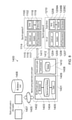
- Fig. 1 shows a system 2100 for generating a model of an area of a patient subject to a surgical procedure.
- Fig. 2 shows a surgical planning device 2200 according to embodiments of the disclosure.
- Fig. 3 shows surgery on a patient 106 by a surgeon using an open surgery system.
- Fig. 4 shows some components of the control apparatus 100.
- Fig. 5 schematically shows a first example of a computer assisted surgery system to which the present technique is applicable.
- Fig. 6 schematically shows a second example of a computer assisted surgery system to which the present technique is applicable.
- Fig. 7 schematically shows a third example of a computer assisted surgery system to which the present technique is applicable.
- Fig. 8 schematically shows a fourth example of a computer assisted surgery system to which the present technique is applicable.
- Fig. 9 schematically shows an example of an arm unit.
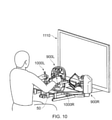
- Fig. 10 schematically shows an example of a master console.
- the present disclosure relates to a device, method, system and computer program that allows a surgeon to be made aware of the impact of a surgical action on the patient’s subsequent condition.
- This subsequent condition may be associated with short term post-operative recovery or may be associated with longer term (or sometimes permanent) changes to the patient.
- the surgical action may relate to a change to corneal lens geometry which will affect postoperative vision or may be the movement dynamics which will affect the postoperative mobility and recovery.
- this is achieved by simulating the patient’s resultant motile system dynamics in real-time with a change to the motile system caused by the surgical action being modelled before it is carried out on the patient.
- the simulation is generated using the output of a model of the patient.
- the common movements which will be most affected by the planned surgical action is demonstrated to the surgeon.
- the simulation is used to adjust the planned surgical action which may be suggested to the surgeon or implemented by a surgical robot such that any negative impact on the patient’s mobility or eye-sight is reduced.
- the disclosure is comprised of three main steps:
- a model of the patient is created which represents the area of surgery being carried out.
- This model may be the patient’s eye (or ophthalmic system) for ophthalmic surgery or may be the patient’s musculoskeletal system for surgery on a limb such as a leg or the like.
- eye or ophthalmic system
- musculoskeletal system for surgery on a limb such as a leg or the like.
- the disclosure is not so limited and any area that is capable of being modelled is envisaged.
- a surgeon uses a surgical planning environment linked to the model to plan the surgical procedure on the patient.
- the surgical planning environment uses the model to inform the surgeon of the post-surgery implications and impact of their planned actions on the patient. For example, in the context of ophthalmic surgery, the improvement to the patient’s vision is shown to the surgeon using the corneal model with a stimulus applied adjusted for the ablation. Moreover, in the context of musculoskeletal surgery, the implication of an incision in the musculoskeletal frame of the patient is modelled and the impact on the patient is shown to the surgeon by applying a stimulus to the model.
- the dynamic function of the modelled system (the musculoskeletal model or the corneal model) is modelled.
- the natural movement of the model, given the proposed surgical action is determined and the impact of that proposed surgical action provided to the surgeon.
- the model therefore demonstrates the new movement capabilities of the system given the planned change to the system, including coping strategies.
- step 3 When step 3 is carried out during the surgery, this reduces the risk of the surgeon causing unintended significant harm to the patient. Moreover, by understanding the implications of the surgical procedure, better post-operative care may be provided to the patient. For example, if an incision would affect the patient’s mobility more than planned, the patient may be provided with correct physiotherapy or equipment such as a wheelchair to aid their recovery.
- a demonstration of the patient’s post-surgery condition into the future may be provided. This may be provided over a number of timeframes. This will be explained later.
- ⁇ Model> As described above, a model of the patient is created. A system 2100 for generating the model is shown in Fig. 1. Specifically, a system 2100 for generating a model of the patients’ body in the area of the planned surgery is shown in Fig. 1.
- a patient 2105 having a model generated of their eye 2110 in preparation for ophthalmic surgery.
- a sensor 2115 is shown.
- the sensor 2115 is configured to collect measurements about one or more physical parameters of the patient’s body in the area of the planned surgery.
- the sensor 2115 may be a camera collecting image data of the patient’s eye 2110 or may be another non-contact mechanism for collecting or inferring measurements from the patient using known optical/LASER, ultrasonic or RADAR techniques.
- the disclosure is not limited to ophthalmic surgery, the following parameters may be collected or inferred from the sensor 2115 in relation to ophthalmic surgery.
- ⁇ Surface curvature of the cornea using corneal topography in embodiments ⁇ Thickness of the retina, as well as its constituent layers, using optical coherence tomography in embodiments ⁇ Eye length and shape, using optical low coherence reflectometry in embodiments ⁇ Eye refraction (and refractive error, or spherical equivalent), using a retinoscope or autorefractor in embodiments ⁇ Corneal hysteresis, and corneal resistance factor, using an ocular response analyzer in embodiments ⁇ Eye pressure, possibly using a tonometer in embodiments ⁇ Wavefront error, possibly using a wavefront aberrometer in embodiments
- the selection of the parameters to be measured is made, in embodiments, based upon a correlation with patient outcomes. For example, the parameters that have the highest correlation with a particular patient outcome are selected.
- the parameters are provided to a modelling device 2120.
- the sensor 2115 may be connected to the modelling device 2120 with either a wired or wireless connection or may be connected over a network (not shown) such as a Local Area Network or a Wide Area Network such as the Internet.
- the modelling device 2120 comprises storage 2125 and circuitry 2130.
- the storage 2125 may be a magnetically readable storage medium, solid state storage medium or the like.
- the circuitry 2130 may be any kind of physical circuitry (such as an Application Specific Integrated Circuit, microprocessor or the like) that is configured to operate under the control of software stored within the storage 2125.
- the circuitry 2130 is configured to receive the parameters from the sensor 2115. The functionality of the software stored on the storage 2125 will be described later.
- other information specific to the patient may be collected and provided to the circuitry 2130.
- personal data of the patient such as age, gender, race, previous or ongoing medical conditions and the like may also be collected from the patient.
- the software stored on the storage 2125 uses collected parameters and the other information in a model to generate a representation of the patient and specifically, a representation of the area of surgery on the patient.
- a model such as that described in US20070073905A1 is used.
- the model described in US20070073905A1 is incorporated herein by reference. For brevity, the modelling technique will not be described further.
- the patient model in US20070073905A1 is created using finite element analysis. Therefore, the patient’s eye is represented by a finite element model requiring the parameters collected by the sensor 2115 and optionally the other information as its input.
- the other information relating to the patient is correlated against similar information collected from historical surgical outcomes to predict the impact the planned surgical actions will have on the patient and how these planned actions will affect the postoperative vision of the patient.
- the finite element model will be altered by the planned surgical procedure and the predicted outcome of such an alteration will be generated.
- the finite element model will be adapted to determine the post-operative refractive error and refractive power of the patient’s eye.
- a mechanism such as that described in [2] is used.
- a detailed finite element method is used to predict the outcome of refractive surgery by modelling of the cornea. This predicts the post-operative corneal shape (such as surface curvature and thickness) and provides an estimation of the patient’s focal and vision capability.
- model described in [3] may be used.
- the content of [3] is herein incorporated by reference.
- the model described in [3] is herein incorporated by reference.
- the elements of the model to work in combination to accurately represent the various mechanisms of the patient’s musculoskeletal system, such as the freedom of movement of joints, relative strengths of muscles, and how these components interact with one another.
- the model also includes external physical environments like the effect of gravity, the floor on which the patient is standing, and any other constraints such as prosthetic limbs.
- the model is trained to simulate the extension and contraction of muscles and associated movement of tissues within the model such that a particular mobility action (such as focusing the eye, moving the eye, walking, climbing stairs) of the modelled patient may be affected.
- a particular mobility action such as focusing the eye, moving the eye, walking, climbing stairs
- a machine learning algorithm developed in [3] is used to enable the model of the patient to ‘learn’ how to accomplish these requested mobility actions given the constraints created by the patient’s specific musculoskeletal system.
- the system of [3] proposes using motion capture of a person performing a particular action (such as walking, dancing, climbing stairs), and the model iterates to find the required control policy to provide muscle activations at each point in time for the model of the patient to reproduce similar movements.
- the model combines such data to create a model of the patient which matches the patient in the area of intended surgery.
- the model may be:
- a 3D mesh of finite elements (such as in US20070073905A1 and [2]), each of which store multiple parameters about a specific point in space such as cell type and geometry; in the example of ophthalmic surgery, the geometry of the patient’s cornea and other aspects of their eye.
- the data architecture may be parameterised (such as in [3]), such as storing a musculoskeletal system in terms of lengths, densities, strengths, defects etc of individual muscles, ligaments, tendons, bones etc.
- parameters such as the lens thickness (in US20070073905A1) and the muscle size (in [3]) may need to be established as part of the parameters collected by the sensor 2115.
- the modelling approach creates a physical model of the biological system and then trains the model to perform dynamic functions (such as an eye focusing task or walking or running or the like).
- a dynamic function is a function requiring a degree of movement of one or more body parts. This training occurs over many generations, where the modelled system may learn ways to achieve a dynamic function goal (such as fast focusing or running or the like) by iteratively improving the way it actuates the modelled system.
- a first generation of the model is the model noted above with the proposed surgical action applied to it.
- the relationship between model generations and time taken for the patient to improve is determined by observation of post-operative patients.
- generations of the model therefore reflect a timeframe which the human will take to perform the same adaptation, with generation 0 being the human’s experience and function immediately after surgery, and generation n being the point at which the generations stop improving.
- the parameters of the model which represent the biological tissues such as muscle strength, tissue stiffness etc. may be permitted to change over generations of the model to reflect improvements in these physical parameters.
- the optimisation function which performs the generational search and improvement within the parameter space is not performed differently, but more parameters may be included in the search spaces.
- the values of the permitted iterative variation in these physical and control function parameters may be defined by the patient’s age, gender and other factors which define how quickly these parameters will be able to change in the real world.
- a surgical planning device After the model has been created, the model is provided to a surgical planning device.
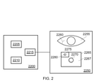
- An embodiment of a surgical planning device 2200 is shown in Fig. 2.
- FIG. 2 shows a surgical planning device 2200 according to embodiments of the disclosure.
- the surgical planning device 2200 is connected to a display 2250.
- This connection may be made in a wired or wireless manner. Indeed, the connection may be made over a network.
- the surgical planning device 2200 includes circuitry.
- This circuitry includes processing circuitry 2205 which operates under the control of computer software.
- the computer software is stored as computer readable code stored on storage 2210.
- the storage 2210 may be solid state storage, magnetically readable storage or the like.
- the storage 2210 also includes, in embodiments, the patient model defined by the system 2100. Of course, the disclosure is not so limited and the patient model may be obtained over a communication link to the system 2100 (not shown).
- the circuitry also includes display circuitry 2215 which connects to display 2250 over the connection.
- the patient model is used to display a graphical representation of the patient model.
- the area of the patient’s body where surgery will take place is defined by the patient model and that patient model is then displayed to the surgeon.
- the surgery is ophthalmic surgery and so a graphical representation of the patent’s ophthalmic system 2255 is shown.
- This representation may be a two dimensional or a three dimensional representation.
- the graphical representations is in two dimensions.
- the graphical representation may be in three dimensions.
- the graphical representation may be holographic.
- the proposed ablation 2260 is an incision the surgeon proposes to make to patient’s ophthalmic system.
- the proposed ablation 2260 may be made to reduce the thickness of a specified part of the patient’s cornea.
- the surgeon may interact with the graphical representation directly in order to define the position, direction, depth and length of the ablation.
- the display 2250 may include a touchscreen that the surgeon can interact with to define the proposed ablation.
- a speech recognition system may translate a verbal command given by the surgeon into the proposed ablation.
- the proposed ablation may then be displayed to the surgeon for the surgeon to confirm that the proposed ablation is positioned correctly.
- the position, angle and movement of a surgical device defines the proposed ablation.
- sensors monitoring the angle and position of the surgeon’s hand or the surgical device such as accelerometers, gyroscopes or images captured by a camera may define the proposed ablation.
- the device is configured to: receive one of i) a voice input from the surgeon, ii) a touch input on a graphical representation of the model from the surgeon, or iii) positional information from a surgical tool.
- surgeon may also provide the time frame over which the surgeon wants to model the effect of the proposed ablation. As noted above, this timeframe is determined by examining real-world post-operative scenarios.
- the proposed ablation is then applied to the patient model.
- the patient model is then iterated to include the proposed ablation.
- the patient model is updated to account for the proposed ablation being made.
- the patient model is updated to determine the effect of the ablation on the corneal thickness.
- the impact section 2265 shows the surgeon the effect of the proposed ablation 2260 on the patient.
- the impact section 2265 graphically represents the effect of the proposed surgical action on the patient by applying the iterated patient model to a stimulus. That is, a stimulus is applied to the updated model to produce an output. The output is then displayed to the surgeon in the impact section 2265.
- the impact section 2265 is comprised of a non-ablation section 2267 and an ablation section 2275.
- the non-ablation section 2267 shows the vision the patient will have of a given stimulus (a circle) where the proposed ablation is not made. As will be apparent, the circle 2270 is out of focus.
- the vision of the patient using the patient model derived by the system 2100 for a given stimulus as is known. For example, it is possible to predict the vision of the patient using regression analysis of the patient data which may be interrogated by means of a look up table, or multidimensional surface plot of parameters. Specifically, data about the patient’s corneal peripheral thickness correlates with postoperative aberration and when the proposed ablation is planned, the aberration can therefore be predicted. The predicted aberration is then used to determine the impact of the patient’s vision on the given stimulus.
- the output vision is a post-surgical performance indicator in the context of ophthalmic surgery. However, it is understood that the disclosure is not so limited and the post-surgical performance indicator may include any indicator that define the impact of the proposed surgical procedure on the output of the updated for the given stimulus.
- the iterated patient model is used to define the vision the patient will have where the proposed ablation is made.
- the circle 2280 in this case is more in focus than the circle 2270 in the non-ablation section 2267.
- the vision of the patient is defined using the patient model iterated for the proposed ablation given the same stimulus. The application of the stimulus to the model to define the vision shown is described above with reference to the non-ablation section 2267.
- the given stimulus is a circle in embodiments, the disclosure is not so limited.
- the stimulus may be a given view such as a Snellen or LogMAR chart, or a simple object such as a house.
- the surgical planning device 2200 is a device for predicting post-surgical performance of a patient, comprising circuitry configured to: receive a model of an area of a patient subject to a surgical procedure; receive an input from a surgeon indicating a proposed surgical action on the patient in the area; update the model based upon the proposed surgical action; apply a stimulus to the updated model to produce a a post-surgical performance indicator and output the post-surgical performance indicator.
- Fig. 2 shows an embodiment for ophthalmic surgery
- the disclosure is not limited.
- the surgical procedure related to a patient’s musculoskeletal system an appropriate patient model will be derived by the system 2100.
- the proposed incision may be in a patient’s left quadriceps muscle.
- the proposed incision will be made to a graphical representation of a patient’s leg. This incision will affect the patient’s post-operative strength. This may have an impact on other parts of the patient’s lower body.
- the patient’s right leg muscles may strengthen to compensate for the reduced weakness in the patient’s left quadriceps muscle.
- the model defined in [3] requires that the patient model must ‘learn’ how to perform a specific mobility action after the planned surgical action is conducted. The model is then iteratively updated over longer time periods to simulate long term patient outcomes.
- the individual musculoskeletal (or other) parameters of the patient model (such as size, strength, location of musculoskeletal elements, and their freedom of movement) are thus updated to reflect changes caused by planned surgical action.
- the impact section 2265 in the case of a musculoskeletal surgical procedure may be an animation showing how the patients gait or mobility changes over time with the proposed incision.
- the post-surgical performance indicator is the animation showing how the patient’s gait or mobility changes over time with the proposed surgical action.
- a proposed surgical action such as the ablation or incision
- the proposed ablation or incision may be cancelled and a second proposed ablation or incision may be made.
- the surgeon may wish to practice the proposed ablation or incision in a surgical simulation system.
- the surgeon may practice performing the ablation or incision in a training simulator that has the patient model loaded thereon.
- the position and movement of one or more surgical tools may be derived using sensors located on the surgical tool or from images captured of the surgeon.
- the position of the surgical tool may then be used to calculated where the incision or ablation is made by the surgeon in the training environment and this may be applied to the patient model.
- the impact section 2265 may be updated to show the effect on the patient of the practiced ablation or incision.
- the surgical planning device 2200 may propose a surgical action to the surgeon.
- the surgical planning device 2200 may apply a plurality of different surgical actions to the model and analyse the derived post-surgical performance indicator.
- the surgical planning device 2200 may apply a different surgical action to the model and obtain the post-surgical performance indicator for each different surgical action.
- the choice of which different surgical action to apply to the model may be selected randomly or may be selected from surgical actions performed in past operations. The use of a random surgical action increases the chance of a previously never tried action that may have an advantageous consequence for the patient.
- the surgical planning device 2200 may then select a surgical action from a plurality of other proposed surgical actions, the selection being made on the basis of the post-surgical performance indicator applicable to that other proposed surgical action when applied to the updated model.
- the surgical planning device 2200 reviews the generated post-surgical performance indicators and selects the surgical action (such as an ablation or incision) that achieves the best post-surgical performance indicator.
- the surgical planning device 2200 displays the selected surgical action to the surgeon. This allows the surgeon to be provided with alternative surgical actions that with improve the likelihood of successful post-surgical performance. Moreover, these actions may not have been considered by the surgeon previously.
- the circuitry within the surgical planning device 2200 is, in embodiments, configured to display a navigation of the selected surgical action to the surgeon.
- the surgical planning device 2200 provides instructions (either visual or aural) to the surgeon to perform the surgical action.
- the selection is made during the surgical procedure and the navigation is performed interactively. This allows the surgeon to be guided to perform the surgical action.
- the patient model may have the ability to exaggerate certain aspects of the patient’s future mobility, to emphasize and highlight small details which result in a disproportionately large effect into the future.
- additional algorithmic process is included to detect the occurrence of known poor outcomes in the model. This may consist of a standard machine learning medical condition detection algorithm which is trained for example to detect signs of posterior capsule opacity, or other common negative outcomes of cataract surgery. In the case of displaying Patient motile system impacts, this may involve using false colours to illustrate muscle imbalances or deviations from known safe limits. These may be generated for example using AI attention mapping techniques to determine the relevant parametric variables of the model which have led to the detection of a bad outcome.
- images may be displayed which predict the view of an object as perceived by the patient, which are defocused or otherwise blurred.
- the blurring could be artificially increased when the system predicts the patient will not result in having perfect vision, so as to make the negative condition more noticeable.
- the disclosure also allows the surgeon to predict the impact of a surgical procedure on a patient during surgery.
- the patient model may be updated during the surgery using data relating to the surgical actions being carried out on the patient.
- the incisions made during the surgery may update the patient model to ensure that when a surgeon makes a proposed surgical procedure (such as an ablation or incision), the patient model will be upto date to determine the impact on the patient of the proposed surgical procedure.
- the circuitry is configured to: receive data relating to surgical actions performed during the surgical procedure; and update the model based upon the received data. This reduces the risk of a mistake being made in the output to the surgeon.
- the disclosure is not so limited.
- the surgeon s next planned surgical action (for example, by analysing the trajectory and speed of a scalpel as it is moved by the surgeon) and displaying the effects that action will have on the patient’s future postoperative condition.
- data collected during a surgery such as video data or robot arm movement and position data may be used, possibly in addition to being used during the model creation phase.
- the safety of the patient may be improved by providing feedback to the surgeon when an adverse post-operative outcome is predicted by the surgical planning device 2200.
- the feedback may be haptic feedback, or may be a visual or aural indication.
- the surgeon will be given the feedback when the surgical planning device 2200 detects that the surgeon is about to perform an action that will negatively affect the patient.
- the feedback may have increasing intensity, or require more force to move in a particular direction when the post-operative condition is determined to be negative.
- the feedback is provided to determine whether the predicted surgical action is adverse to the patient.
- the education and training of a surgeons is improved by illustrating the causal link between specific actions the surgeon takes during a surgical training procedure and the future postoperative condition of their patient, using Augmented Reality or Virtual Reality display and artificial patient data.
- a ‘Virtual Patient’ is digitally constructed, including corresponding patient records. This may be: a An accurate representation of a real patient (which may be anonymised) b An entirely imaginary patient c A composite of a. and b.
- the Virtual Patient may be designed to help deliver a specific learning outcome for the surgeon, such as a specific injury or condition. As such, certain aspects of the Virtual Patient, corresponding patient records, or their patient model may be emphasized.
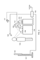
- Fig. 3 shows surgery on a patient 106 by a surgeon using an open surgery system.
- the patient 106 lies on an operating table 105 and a human surgeon 104 and a computerised surgical apparatus 103 perform the surgery together.
- This surgery may be ophthalmic surgery or surgery on the musculoskeletal system of the patient in embodiments.
- the patient model will have been derived by device 2100 and the surgical planning device 2200 may have been used in the pre-surgery planning and/or may be used in the open surgery shown in Fig. 3.
- the surgical planning device 2200 will be included in the system of Fig. 3 although this is not explicitly shown for brevity.
- Each of the human surgeon and computerised surgical apparatus monitor one or more parameters of the surgery, for example, patient data collected from one or more patient data collection apparatuses (e.g. electrocardiogram (ECG) data from an ECG monitor, blood pressure data from a blood pressure monitor, etc. - patient data collection apparatuses are known in the art and not shown or discussed in detail) and one or more parameters determined by analysing images of the surgery (captured by the surgeon’s eyes or a camera 109 of the computerised surgical apparatus) or sounds of the surgery (captured by the surgeon’s ears or a microphone (not shown) of the computerised surgical apparatus).
- Each of the human surgeon and computerised surgical apparatus carry out respective tasks during the surgery (e.g. some tasks are carried out exclusively by the surgeon, some tasks are carried out exclusively by the computerised surgical apparatus and some tasks are carried out by both the surgeon and computerised surgical apparatus) and make decisions about how to carry out those tasks using the monitored one or more surgical parameters.
- the surgical data includes movement data of a surgical tool and the surgical robot collected from sensors located within the tool or robot or by tracking the tool or robot and any feedback provided by that tool or robot.
- sensors include accelerometers, gyroscopes, or other sensors located within surgical tools such as forceps, tweezers, scalpels, electrodiathermy units or the surgical robot arm that indicates the motion and force of the tool.
- the control data provided by the experienced surgeon is also captured.
- the surgical planning device 2200 of embodiments may be used by the surgeon during the open surgery and, indeed, this surgical data may be provided to the surgical planning device 2200 during the surgery to ensure that the patient model is kept upto date. This means that should the surgeon require the predicted outcome of a proposed surgical action to be determined by the surgical planning system of Fig. 2 during the surgery, the patient model within the surgical planning device 2200 will be current.
- image data from cameras showing the surgeon’s viewpoint and/or image data from an endoscope or a surgical microscope or an exoscope, or any surgical instrument used in the surgical procedure is captured.
- This image data may be RGB type image data or may be fluorescent video or the like.
- image data of the surgical procedure is image data obtained by the surgical instrument.
- Fig. 3 shows an open surgery system
- the surgical planning device 2200 of embodiments may be used with any kind of surgical procedure.
- the surgical planning device 2200 of embodiments is also applicable to other computer assisted surgery systems where the computerised surgical apparatus (e.g. which holds the medical scope in a computer-assisted medical scope system or which is the slave apparatus in a master-slave system) is able to make decisions which might conflict with the surgeon’s decisions.
- the computerised surgical apparatus is therefore a surgical apparatus comprising a computer which is able to make a decision about the surgery using one or more monitored parameters of the surgery.
- the computerised surgical apparatus 103 of Fig. 3 is a surgical robot capable of making decisions and undertaking autonomous actions based on images captured by the camera 109.
- the robot 103 comprises a controller 110 and one or more surgical tools 107 (e.g. movable scalpel, clamp or robotic hand).
- the controller 110 is connected to the camera 109 for capturing images of the surgery, to a movable camera arm 112 for adjusting the position of the camera 109 and to adjustable surgical lighting 111 which illuminates the surgical scene and has one or more adjustable lighting parameters such as brightness and colour.
- the adjustable surgical lighting comprises a plurality of light emitting diodes (LEDs, not shown) of different respective colours.
- the brightness of each LED is individually adjustable (by suitable control circuitry (not shown) of the adjustable surgical lighting) to allow adjustment of the overall colour and brightness of light output by the LEDs.
- the controller 110 is also connected to a control apparatus 100.
- the control apparatus 100 is connected to another camera 108 for capturing images of the surgeon’s eyes for use in gaze tracking and to an electronic display 102 (e.g. liquid crystal display) held on a stand 102 so the electronic display 102 is viewable by the surgeon 104 during the surgery.
- the control apparatus 100 compares the visual regions of the surgical scene paid attention to by the surgeon 104 and robot 103 to help resolve conflicting surgeon and computer decisions according to the present technique.
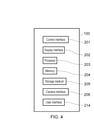
- Fig. 4 shows some components of the control apparatus 100.
- the control apparatus 100 comprises a control interface 201 for sending electronic information to and/or receiving electronic information from the controller 110, a display interface 202 for sending electronic information representing information to be displayed to the electronic display 102, a processor 203 for processing electronic instructions, a memory 204 for storing the electronic instructions to be processed and input and output data associated with the electronic instructions, a storage medium 205 (e.g. a hard disk drive, solid state drive or the like) for long term storage of electronic information, a camera interface 206 for receiving electronic information representing images of the surgeon’s eyes captured by the camera 108 and the image data noted above and a user interface 214 (e.g. comprising a touch screen, physical buttons, a voice control system or the like).
- a control interface 201 for sending electronic information to and/or receiving electronic information from the controller 110
- a display interface 202 for sending electronic information representing information to be displayed to the electronic display 102
- a processor 203 for processing electronic instructions
- a memory 204 for storing the electronic instructions to be processed and input and output
- control interface 201 controls the operation of each of the control interface 201, display interface 202, memory 204, storage medium 205, camera interface 206 and user interface 214.
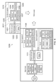
- Fig. 5 schematically shows an example of a computer assisted surgery system 1126 to which the present technique may be applicable.
- the computer assisted surgery system is a master-slave system incorporating an autonomous arm 1100 and one or more surgeon-controlled arms 1101.
- the autonomous arm holds an imaging device 1102 (e.g. a surgical camera or medical vision scope such as a medical endoscope, surgical microscope or surgical exoscope).
- the one or more surgeon-controlled arms 1101 each hold a surgical device 1103 (e.g. a cutting tool or the like).
- the imaging device of the autonomous arm outputs an image of the surgical scene to an electronic display 1110 viewable by the surgeon.
- the autonomous arm autonomously adjusts the view of the imaging device whilst the surgeon performs the surgery using the one or more surgeon-controlled arms to provide the surgeon with an appropriate view of the surgical scene in real time.
- the surgeon controls the one or more surgeon-controlled arms 1101 using a master console 1104.
- the master console includes a master controller 1105.
- the master controller 1105 includes one or more force sensors 1106 (e.g. torque sensors), one or more rotation sensors 1107 (e.g. encoders) and one or more actuators 1108.
- the master console includes an arm (not shown) including one or more joints and an operation portion. The operation portion can be grasped by the surgeon and moved to cause movement of the arm about the one or more joints.
- the one or more force sensors 1106 detect a force provided by the surgeon on the operation portion of the arm about the one or more joints.
- the one or more rotation sensors detect a rotation angle of the one or more joints of the arm.
- the actuator 1108 drives the arm about the one or more joints to allow the arm to provide haptic feedback to the surgeon.
- the master console includes a natural user interface (NUI) input / output for receiving input information from and providing output information to the surgeon.
- NUI input / output includes the arm (which the surgeon moves to provide input information and which provides haptic feedback to the surgeon as output information).
- the NUI input / output may also include voice input, line of sight input and/or gesture input, for example.
- the master console includes the electronic display 1110 for outputting images captured by the imaging device 1102.
- the master console 1104 communicates with each of the autonomous arm 1100 and one or more surgeon-controlled arms 1101 via a robotic control system 1111.
- the robotic control system is connected to the master console 1104, autonomous arm 1100 and one or more surgeon-controlled arms 1101 by wired or wireless connections 1123, 1124 and 1125.
- the connections 1123, 1124 and 1125 allow the exchange of wired or wireless signals between the master console, autonomous arm and one or more surgeon-controlled arms.
- the robotic control system includes a control processor 1112 and a database 1113.
- the control processor 1112 processes signals received from the one or more force sensors 1106 and one or more rotation sensors 1107 and outputs control signals in response to which one or more actuators 1116 drive the one or more surgeon controlled arms 1101. In this way, movement of the operation portion of the master console 1104 causes corresponding movement of the one or more surgeon controlled arms.
- the control processor 1112 also outputs control signals in response to which one or more actuators 1116 drive the autonomous arm 1100.
- the control signals output to the autonomous arm are determined by the control processor 1112 in response to signals received from one or more of the master console 1104, one or more surgeon-controlled arms 1101, autonomous arm 1100 and any other signal sources (not shown).
- the received signals are signals which indicate an appropriate position of the autonomous arm for images with an appropriate view to be captured by the imaging device 1102.
- the database 1113 stores values of the received signals and corresponding positions of the autonomous arm.
- a corresponding position of the autonomous arm 1100 is set so that images captured by the imaging device 1102 are not occluded by the one or more surgeon-controlled arms 1101.
- a corresponding position of the autonomous arm is set so that images are captured by the imaging device 1102 from an alternative view (e.g. one which allows the autonomous arm to move along an alternative path not involving the obstacle).
- the control processor 1112 looks up the values of the received signals in the database 1112 and retrieves information indicating the corresponding position of the autonomous arm 1100. This information is then processed to generate further signals in response to which the actuators 1116 of the autonomous arm cause the autonomous arm to move to the indicated position.
- Each of the autonomous arm 1100 and one or more surgeon-controlled arms 1101 includes an arm unit 1114.
- the arm unit includes an arm (not shown), a control unit 1115, one or more actuators 1116 and one or more force sensors 1117 (e.g. torque sensors).
- the arm includes one or more links and joints to allow movement of the arm.
- the control unit 1115 sends signals to and receives signals from the robotic control system 1111.
- the control unit 1115 controls the one or more actuators 1116 to drive the arm about the one or more joints to move it to an appropriate position.
- the received signals are generated by the robotic control system based on signals received from the master console 1104 (e.g. by the surgeon controlling the arm of the master console).
- the received signals are generated by the robotic control system looking up suitable autonomous arm position information in the database 1113.
- the control unit 1115 In response to signals output by the one or more force sensors 1117 about the one or more joints, the control unit 1115 outputs signals to the robotic control system. For example, this allows the robotic control system to send signals indicative of resistance experienced by the one or more surgeon-controlled arms 1101 to the master console 1104 to provide corresponding haptic feedback to the surgeon (e.g. so that a resistance experienced by the one or more surgeon-controlled arms results in the actuators 1108 of the master console causing a corresponding resistance in the arm of the master console). As another example, this allows the robotic control system to look up suitable autonomous arm position information in the database 1113 (e.g. to find an alternative position of the autonomous arm if the one or more force sensors 1117 indicate an obstacle is in the path of the autonomous arm).
- the imaging device 1102 of the autonomous arm 1100 includes a camera control unit 1118 and an imaging unit 1119.
- the camera control unit controls the imaging unit to capture images and controls various parameters of the captured image such as zoom level, exposure value, white balance and the like.
- the imaging unit captures images of the surgical scene.
- the imaging unit includes all components necessary for capturing images including one or more lenses and an image sensor (not shown). The view of the surgical scene from which images are captured depends on the position of the autonomous arm.
- the surgical device 1103 of the one or more surgeon-controlled arms includes a device control unit 1120, manipulator 1121 (e.g. including one or more motors and/or actuators) and one or more force sensors 1122 (e.g. torque sensors).
- manipulator 1121 e.g. including one or more motors and/or actuators
- force sensors 1122 e.g. torque sensors
- the device control unit 1120 controls the manipulator to perform a physical action (e.g. a cutting action when the surgical device 1103 is a cutting tool) in response to signals received from the robotic control system 1111.
- the signals are generated by the robotic control system in response to signals received from the master console 1104 which are generated by the surgeon inputting information to the NUI input / output 1109 to control the surgical device.
- the NUI input / output includes one or more buttons or levers comprised as part of the operation portion of the arm of the master console which are operable by the surgeon to cause the surgical device to perform a predetermined action (e.g. turning an electric blade on or off when the surgical device is a cutting tool).
- the device control unit 1120 also receives signals from the one or more force sensors 1122. In response to the received signals, the device control unit provides corresponding signals to the robotic control system 1111 which, in turn, provides corresponding signals to the master console 1104.
- the master console provides haptic feedback to the surgeon via the NUI input / output 1109. The surgeon therefore receives haptic feedback from the surgical device 1103 as well as from the one or more surgeon-controlled arms 1101.
- the haptic feedback involves the button or lever which operates the cutting tool to give greater resistance to operation when the signals from the one or more force sensors 1122 indicate a greater force on the cutting tool (as occurs when cutting through a harder material, e.g.
- the NUI input / output 1109 includes one or more suitable motors, actuators or the like to provide the haptic feedback in response to signals received from the robot control system 1111.
- Fig. 6 schematically shows another example of a computer assisted surgery system 1209 to which the present technique is applicable.
- the computer assisted surgery system 1209 is a surgery system in which the surgeon performs tasks via the master-slave system 1126 and a computerised surgical apparatus 1200 performs tasks autonomously.
- the master-slave system 1126 is the same as Fig. 3and is therefore not described.
- the master-slave system may, however, be a different system to that of Fig. 3 in alternative embodiments or may be omitted altogether (in which case the system 1209 works autonomously whilst the surgeon performs conventional surgery).
- the computerised surgical apparatus 1200 includes a robotic control system 1201 and a tool holder arm apparatus 1210.
- the tool holder arm apparatus 1210 includes an arm unit 1204 and a surgical device 1208.
- the arm unit includes an arm (not shown), a control unit 1205, one or more actuators 1206 and one or more force sensors 1207 (e.g. torque sensors).
- the arm includes one or more joints to allow movement of the arm.
- the tool holder arm apparatus 1210 sends signals to and receives signals from the robotic control system 1201 via a wired or wireless connection 1211.
- the robotic control system 1201 includes a control processor 1202 and a database 1203. Although shown as a separate robotic control system, the robotic control system 1201 and the robotic control system 1111 may be one and the same.
- the surgical device 1208 has the same components as the surgical device 1103.
- control unit 1205 controls the one or more actuators 1206 to drive the arm about the one or more joints to move it to an appropriate position.
- the operation of the surgical device 1208 is also controlled by control signals received from the robotic control system 1201.
- the control signals are generated by the control processor 1202 in response to signals received from one or more of the arm unit 1204, surgical device 1208 and any other signal sources (not shown).
- the other signal sources may include an imaging device (e.g. imaging device 1102 of the master-slave system 1126) which captures images of the surgical scene.
- the values of the signals received by the control processor 1202 are compared to signal values stored in the database 1203 along with corresponding arm position and/or surgical device operation state information.
- the control processor 1202 retrieves from the database 1203 arm position and/or surgical device operation state information associated with the values of the received signals. The control processor 1202 then generates the control signals to be transmitted to the control unit 1205 and surgical device 1208 using the retrieved arm position and/or surgical device operation state information.
- signals received from an imaging device which captures images of the surgical scene indicate a predetermined surgical scenario (e.g. via neural network image classification process or the like)
- the predetermined surgical scenario is looked up in the database 1203 and arm position information and/or surgical device operation state information associated with the predetermined surgical scenario is retrieved from the database.
- signals indicate a value of resistance measured by the one or more force sensors 1207 about the one or more joints of the arm unit 1204
- the value of resistance is looked up in the database 1203 and arm position information and/or surgical device operation state information associated with the value of resistance is retrieved from the database (e.g. to allow the position of the arm to be changed to an alternative position if an increased resistance corresponds to an obstacle in the arm’s path).
- control processor 1202 then sends signals to the control unit 1205 to control the one or more actuators 1206 to change the position of the arm to that indicated by the retrieved arm position information and/or signals to the surgical device 1208 to control the surgical device 1208 to enter an operation state indicated by the retrieved operation state information (e.g. turning an electric blade to an “on” state or “off” state if the surgical device 1208 is a cutting tool).
- an operation state indicated by the retrieved operation state information e.g. turning an electric blade to an “on” state or “off” state if the surgical device 1208 is a cutting tool.
- Fig. 7 schematically shows another example of a computer assisted surgery system 1300 to which the present technique is applicable.
- the computer assisted surgery system 1300 is a computer assisted medical scope system in which an autonomous arm 1100 holds an imaging device 1102 (e.g. a medical scope such as an endoscope, microscope or exoscope).
- the imaging device of the autonomous arm outputs an image of the surgical scene to an electronic display (not shown) viewable by the surgeon.
- the autonomous arm autonomously adjusts the view of the imaging device whilst the surgeon performs the surgery to provide the surgeon with an appropriate view of the surgical scene in real time.
- the autonomous arm 1100 is the same as that of Fig. 12 and is therefore not described.
- the autonomous arm is provided as part of the standalone computer assisted medical scope system 1300 rather than as part of the master-slave system 1126 of Fig. 12.
- the autonomous arm 1100 can therefore be used in many different surgical setups including, for example, laparoscopic surgery (in which the medical scope is an endoscope) and open surgery.
- the computer assisted medical scope system 1300 also includes a robotic control system 1302 for controlling the autonomous arm 1100.
- the robotic control system 1302 includes a control processor 1303 and a database 1304. Wired or wireless signals are exchanged between the robotic control system 1302 and autonomous arm 1100 via connection 1301.
- control unit 1115 controls the one or more actuators 1116 to drive the autonomous arm 1100 to move it to an appropriate position for images with an appropriate view to be captured by the imaging device 1102.
- the control signals are generated by the control processor 1303 in response to signals received from one or more of the arm unit 1114, imaging device 1102 and any other signal sources (not shown).
- the values of the signals received by the control processor 1303 are compared to signal values stored in the database 1304 along with corresponding arm position information.
- the control processor 1303 retrieves from the database 1304 arm position information associated with the values of the received signals.
- the control processor 1303 then generates the control signals to be transmitted to the control unit 1115 using the retrieved arm position information.
- signals received from the imaging device 1102 indicate a predetermined surgical scenario (e.g. via neural network image classification process or the like)
- the predetermined surgical scenario is looked up in the database 1304 and arm position information associated with the predetermined surgical scenario is retrieved from the database.
- signals indicate a value of resistance measured by the one or more force sensors 1117 of the arm unit 1114
- the value of resistance is looked up in the database 1203 and arm position information associated with the value of resistance is retrieved from the database (e.g. to allow the position of the arm to be changed to an alternative position if an increased resistance corresponds to an obstacle in the arm’s path).
- the control processor 1303 then sends signals to the control unit 1115 to control the one or more actuators 1116 to change the position of the arm to that indicated by the retrieved arm position information.
- Fig. 8 schematically shows another example of a computer assisted surgery system 1400 to which the present technique is applicable.
- the system includes one or more autonomous arms 1100 with an imaging unit 1102 and one or more autonomous arms 1210 with a surgical device 1210.
- the one or more autonomous arms 1100 and one or more autonomous arms 1210 are the same as those previously described.
- Each of the autonomous arms 1100 and 1210 is controlled by a robotic control system 1408 including a control processor 1409 and database 1410. Wired or wireless signals are transmitted between the robotic control system 1408 and each of the autonomous arms 1100 and 1210 via connections 1411 and 1412, respectively.
- the robotic control system 1408 performs the functions of the previously described robotic control systems 1111 and/or 1302 for controlling each of the autonomous arms 1100 and performs the functions of the previously described robotic control system 1201 for controlling each of the autonomous arms 1210.
- the autonomous arms 1100 and 1210 perform at least a part of the surgery completely autonomously (e.g. when the system 1400 is an open surgery system).
- the robotic control system 1408 controls the autonomous arms 1100 and 1210 to perform predetermined actions during the surgery based on input information indicative of the current stage of the surgery and/or events happening in the surgery.
- the input information includes images captured by the image capture device 1102.
- the input information may also include sounds captured by a microphone (not shown), detection of in-use surgical instruments based on motion sensors comprised with the surgical instruments (not shown) and/or any other suitable input information.
- the input information is analysed using a suitable machine learning (ML) algorithm (e.g. a suitable artificial neural network) implemented by machine learning based surgery planning apparatus 1402.
- ML machine learning
- the planning apparatus 1402 includes a machine learning processor 1403, a machine learning database 1404 and a trainer 1405.
- the machine learning database 1404 includes information indicating classifications of surgical stages (e.g. making an incision, removing an organ or applying stitches) and/or surgical events (e.g. a bleed or a patient parameter falling outside a predetermined range) and input information known in advance to correspond to those classifications (e.g. one or more images captured by the imaging device 1102 during each classified surgical stage and/or surgical event).
- the machine learning database 1404 is populated during a training phase by providing information indicating each classification and corresponding input information to the trainer 1405.
- the trainer 1405 uses this information to train the machine learning algorithm (e.g. by using the information to determine suitable artificial neural network parameters).
- the machine learning algorithm is implemented by the machine learning processor 1403.
- previously unseen input information e.g. newly captured images of a surgical scene
- the machine learning database also includes action information indicating the actions to be undertaken by each of the autonomous arms 1100 and 1210 in response to each surgical stage and/or surgical event stored in the machine learning database (e.g. controlling the autonomous arm 1210 to make the incision at the relevant location for the surgical stage “making an incision” and controlling the autonomous arm 1210 to perform an appropriate cauterisation for the surgical event “bleed”).
- the machine learning based surgery planner 1402 is therefore able to determine the relevant action to be taken by the autonomous arms 1100 and/or 1210 in response to the surgical stage and/or surgical event classification output by the machine learning algorithm.
- Information indicating the relevant action is provided to the robotic control system 1408 which, in turn, provides signals to the autonomous arms 1100 and/or 1210 to cause the relevant action to be performed.
- the planning apparatus 1402 may be included within a control unit 1401 with the robotic control system 1408, thereby allowing direct electronic communication between the planning apparatus 1402 and robotic control system 1408.
- the robotic control system 1408 may receive signals from other devices 1407 over a communications network 1405 (e.g. the internet). This allows the autonomous arms 1100 and 1210 to be remotely controlled based on processing carried out by these other devices 1407.
- the devices 1407 are cloud servers with sufficient processing power to quickly implement complex machine learning algorithms, thereby arriving at more reliable surgical stage and/or surgical event classifications. Different machine learning algorithms may be implemented by different respective devices 1407 using the same training data stored in an external (e.g. cloud based) machine learning database 1406 accessible by each of the devices.
- Each device 1407 therefore does not need its own machine learning database (like machine learning database 1404 of planning apparatus 1402) and the training data can be updated and made available to all devices 1407 centrally.
- Each of the devices 1407 still includes a trainer (like trainer 1405) and machine learning processor (like machine learning processor 1403) to implement its respective machine learning algorithm.
- Fig. 9 shows an example of the arm unit 1114.
- the arm unit 1204 is configured in the same way.
- the arm unit 1114 supports an endoscope as an imaging device 1102.
- a different imaging device 1102 or surgical device 1103 in the case of arm unit 1114) or 1208 (in the case of arm unit 1204) is supported.
- the arm unit 1114 includes a base 710 and an arm 720 extending from the base 720.
- the arm 720 includes a plurality of active joints 721a to 721f and supports the endoscope 1102 at a distal end of the arm 720.
- the links 722a to 722f are substantially rod-shaped members. Ends of the plurality of links 722a to 722f are connected to each other by active joints 721a to 721f, a passive slide mechanism 724 and a passive joint 726.
- the base unit 710 acts as a fulcrum so that an arm shape extends from the base 710.
- a position and a posture of the endoscope 1102 are controlled by driving and controlling actuators provided in the active joints 721a to 721f of the arm 720.
- a distal end of the endoscope 1102 is caused to enter a patient's body cavity, which is a treatment site, and captures an image of the treatment site.
- the endoscope 1102 may instead be another device such as another imaging device or a surgical device. More generally, a device held at the end of the arm 720 is referred to as a distal unit or distal device.
- the arm unit 700 is described by defining coordinate axes as follows. Furthermore, a vertical direction, a longitudinal direction, and a horizontal direction are defined according to the coordinate axes. In other words, a vertical direction with respect to the base 710 installed on the floor surface is defined as a z-axis direction and the vertical direction. Furthermore, a direction orthogonal to the z axis, the direction in which the arm 720 is extended from the base 710 (in other words, a direction in which the endoscope 1102 is positioned with respect to the base 710) is defined as a y-axis direction and the longitudinal direction. Moreover, a direction orthogonal to the y-axis and z-axis is defined as an x-axis direction and the horizontal direction.
- the active joints 721a to 721f connect the links to each other to be rotatable.
- the active joints 721a to 721f have the actuators, and have each rotation mechanism that is driven to rotate about a predetermined rotation axis by drive of the actuator.
- the passive slide mechanism 724 is an aspect of a passive form change mechanism, and connects the link 722c and the link 722d to each other to be movable forward and rearward along a predetermined direction.
- the passive slide mechanism 724 is operated to move forward and rearward by, for example, a user, and a distance between the active joint 721c at one end side of the link 722c and the passive joint 726 is variable. With the configuration, the whole form of the arm unit 720 can be changed.
- the passive joint 736 is an aspect of the passive form change mechanism, and connects the link 722d and the link 722e to each other to be rotatable.
- the passive joint 726 is operated to rotate by, for example, the user, and an angle formed between the link 722d and the link 722e is variable. With the configuration, the whole form of the arm unit 720 can be changed.
- the arm unit 1114 has the six active joints 721a to 721f, and six degrees of freedom are realized regarding the drive of the arm 720. That is, the passive slide mechanism 726 and the passive joint 726 are not objects to be subjected to the drive control while the drive control of the arm unit 1114 is realized by the drive control of the six active joints 721a to 721f.
- the active joints 721a, 721d, and 721f are provided so as to have each long axis direction of the connected links 722a and 722e and a capturing direction of the connected endoscope 1102 as a rotational axis direction.
- the active joints 721b, 721c, and 721e are provided so as to have the x-axis direction, which is a direction in which a connection angle of each of the connected links 722a to 722c, 722e, and 722f and the endoscope 1102 is changed within a y-z plane (a plane defined by the y axis and the z axis), as a rotation axis direction.
- the active joints 721a, 721d, and 721f have a function of performing so-called yawing
- the active joints 421b, 421c, and 421e have a function of performing so-called pitching.
- the endoscope 1102 can be freely moved within a movable range of the arm 720.
- a hemisphere as an example of the movable range of the endoscope 723.
- RCM remote center of motion
- Fig. 10 shows an example of the master console 1104.
- Two control portions 900R and 900L for a right hand and a left hand are provided.
- a surgeon puts both arms or both elbows on the supporting base 50, and uses the right hand and the left hand to grasp the operation portions 1000R and 1000L, respectively.
- the surgeon operates the operation portions 1000R and 1000L while watching electronic display 1110 showing a surgical site.
- the surgeon may displace the positions or directions of the respective operation portions 1000R and 1000L to remotely operate the positions or directions of surgical instruments attached to one or more slave apparatuses or use each surgical instrument to perform a grasping operation.
- Described embodiments may be implemented in any suitable form including hardware, software, firmware or any combination of these. Described embodiments may optionally be implemented at least partly as computer software running on one or more data processors and/or digital signal processors.
- the elements and components of any embodiment may be physically, functionally and logically implemented in any suitable way. Indeed the functionality may be implemented in a single unit, in a plurality of units or as part of other functional units. As such, the disclosed embodiments may be implemented in a single unit or may be physically and functionally distributed between different units, circuitry and/or processors.
- a device for predicting post-surgical performance of a patient comprising circuitry configured to: receive a model of an area of a patient subject to a surgical procedure; receive an input from a surgeon indicating a proposed surgical action on the patient in the area; update the model based upon the proposed surgical action; apply a stimulus to the updated model to produce a post-surgical performance indicator and output the post-surgical performance indicator.
- the circuitry is configured to: select a surgical action from a plurality of other proposed surgical actions, the selection being made on the basis of the postsurgical performance indicator applicable to that other proposed surgical action when applied to the updated model; and display the selected surgical action to the surgeon.
- circuitry is configured to display a navigation of the selected surgical action to the surgeon.
- the circuitry is configured to display a navigation of the selected surgical action to the surgeon.
- the selection is made during the surgical procedure and the navigation is performed interactively.
- the circuitry is configured to: receive one of i) a voice input from the surgeon, ii) a touch input on a graphical representation of the model from the surgeon, or iii) positional information from a surgical tool.
- the circuitry is configured to further update the model to achieve a dynamic function goal by making iterative changes to the model.
- circuitry is configured to: receive data relating to surgical actions performed during the surgical procedure; and update the model based upon the 10 received data.
- circuitry is configured to: provide the updated model to a surgical training system.
- circuitry is configured to receive a model of at least part of the patient’s ophthalmic system or musculoskeletal system.
- a method for predicting post-surgical performance of a patient comprising: receiving a model of an area of a patient subject to a surgical procedure; receiving an input from a surgeon indicating a proposed surgical action on the patient in the area; update the model based upon the proposed surgical action; applying a stimulus to the updated model to produce a post-surgical performance indicator and output the post-surgical performance indicator.
- a method according to clause (10) comprising: selecting a surgical action from a plurality of other proposed surgical actions, the selection being made on the basis of the post-surgical performance indicator applicable to that other proposed surgical action when applied to the updated model; and displaying the selected surgical action to the surgeon.
- a method according to clause (11) comprising displaying a navigation of the selected surgical action to the surgeon.
- a computer program product comprising computer readable instructions which, when loaded onto a computer, configures the computer to perform a method according to any one of clauses 10 to 18.
Abstract
A device for predicting post-surgical performance of a patient, comprising circuitry configured to: receive a model of an area of a patient subject to a surgical procedure; receive an input from a surgeon indicating a proposed surgical action on the patient in the area; update the model based upon the proposed surgical action; apply a stimulus to the updated model to produce a a post-surgical performance indicator and output the post-surgical performance indicator.
Description
The present technique relates to a device, computer program and method.
The “background” description provided herein is for the purpose of generally presenting the context of the disclosure. Work of the presently named inventors, to the extent it is described in the background section, as well as aspects of the description which may not otherwise qualify as prior art at the time of filing, are neither expressly or impliedly admitted as prior art against the present technique.
Post-operative patient recovery is very important. During surgery, a side-effect is the unintended impaired mobility of the patient. Studies have been carried out to enable better planning during the pre-operative screening to reduce the impact of this [1].
In other types of surgery, a parametric model of a patient’s ophthalmic system particularly relating to refractive ophthalmic surgery is used to determine which ablations to make. This is described in US20070073905A1 (the contents of which are herein incorporated by reference). Here, large historical data sets of patient eye (corneal) measurements, past surgical actions performed, and patient outcomes, are used as an input to a laser ablation (or other intervention) algorithm. The most significant parameters are identified, allowing ablations to be conducted in a manner which maximises likelihood of success. Thus, initial corneal measurements are taken on a patient before ablations are made; then measurements may be retaken to iteratively update and optimise further ablations.
A similar approach to predicting outcomes of refractive surgery by careful multiphysics modelling of the cornea is described by [2]. Here, well understood theories of mechanics are applied to biomechanical systems.
Whilst these systems describe techniques which allow the outcome of surgery to be predicted there is no guidance provided to the surgeon of the impact of surgical actions. This means that the surgical actions performed by the surgeon may be sub-optimal with regard to patient post-operative outcome.
It is an aim of the disclosure to address this issue.
According to embodiments of the disclosure, there is provided a device for predicting post-surgical performance of a patient, comprising circuitry configured to: receive a model of an area of a patient subject to a surgical procedure; receive an input from a surgeon indicating a proposed surgical action on the patient in the area; update the model based upon the proposed surgical action; apply a stimulus to the updated model to produce a a post-surgical performance indicator and output the post-surgical performance indicator.
The foregoing paragraphs have been provided by way of general introduction, and are not intended to limit the scope of the following claims. The described embodiments, together with further advantages, will be best understood by reference to the following detailed description taken in conjunction with the accompanying drawings.
A more complete appreciation of the disclosure and many of the attendant advantages thereof will be readily obtained as the same becomes better understood by reference to the following detailed description when considered in connection with the accompanying drawings.
Referring now to the drawings, wherein like reference numerals designate identical or corresponding parts throughout the several views.
The present disclosure relates to a device, method, system and computer program that allows a surgeon to be made aware of the impact of a surgical action on the patient’s subsequent condition. This subsequent condition may be associated with short term post-operative recovery or may be associated with longer term (or sometimes permanent) changes to the patient. For example, the surgical action may relate to a change to corneal lens geometry which will affect postoperative vision or may be the movement dynamics which will affect the postoperative mobility and recovery. Generally, this is achieved by simulating the patient’s resultant motile system dynamics in real-time with a change to the motile system caused by the surgical action being modelled before it is carried out on the patient. The simulation is generated using the output of a model of the patient. In some instances, the common movements which will be most affected by the planned surgical action is demonstrated to the surgeon. In some instances, the simulation is used to adjust the planned surgical action which may be suggested to the surgeon or implemented by a surgical robot such that any negative impact on the patient’s mobility or eye-sight is reduced.
The disclosure is comprised of three main steps:
1) a model of the patient is created which represents the area of surgery being carried out. This model may be the patient’s eye (or ophthalmic system) for ophthalmic surgery or may be the patient’s musculoskeletal system for surgery on a limb such as a leg or the like. Of course, the disclosure is not so limited and any area that is capable of being modelled is envisaged.
2) a surgeon uses a surgical planning environment linked to the model to plan the surgical procedure on the patient.
3) the surgical planning environment uses the model to inform the surgeon of the post-surgery implications and impact of their planned actions on the patient. For example, in the context of ophthalmic surgery, the improvement to the patient’s vision is shown to the surgeon using the corneal model with a stimulus applied adjusted for the ablation. Moreover, in the context of musculoskeletal surgery, the implication of an incision in the musculoskeletal frame of the patient is modelled and the impact on the patient is shown to the surgeon by applying a stimulus to the model.
Moreover, in embodiments, the dynamic function of the modelled system (the musculoskeletal model or the corneal model) is modelled. In other words, in embodiments, the natural movement of the model, given the proposed surgical action, is determined and the impact of that proposed surgical action provided to the surgeon. The model therefore demonstrates the new movement capabilities of the system given the planned change to the system, including coping strategies.
When step 3 is carried out during the surgery, this reduces the risk of the surgeon causing unintended significant harm to the patient. Moreover, by understanding the implications of the surgical procedure, better post-operative care may be provided to the patient. For example, if an incision would affect the patient’s mobility more than planned, the patient may be provided with correct physiotherapy or equipment such as a wheelchair to aid their recovery.
In the other embodiments, where a dynamic function is provided, a demonstration of the patient’s post-surgery condition into the future may be provided. This may be provided over a number of timeframes. This will be explained later.
<Model>
As described above, a model of the patient is created. Asystem 2100 for generating the model is shown in Fig. 1. Specifically, a system 2100 for generating a model of the patients’ body in the area of the planned surgery is shown in Fig. 1.
As described above, a model of the patient is created. A
Specifically, a patient 2105 is shown having a model generated of their eye 2110 in preparation for ophthalmic surgery. A sensor 2115 is shown. The sensor 2115 is configured to collect measurements about one or more physical parameters of the patient’s body in the area of the planned surgery. In embodiments, the sensor 2115 may be a camera collecting image data of the patient’s eye 2110 or may be another non-contact mechanism for collecting or inferring measurements from the patient using known optical/LASER, ultrasonic or RADAR techniques. Although the disclosure is not limited to ophthalmic surgery, the following parameters may be collected or inferred from the sensor 2115 in relation to ophthalmic surgery.
・ Surface curvature of the cornea, using corneal topography in embodiments
・ Thickness of the retina, as well as its constituent layers, using optical coherence tomography in embodiments
・ Eye length and shape, using optical low coherence reflectometry in embodiments
・ Eye refraction (and refractive error, or spherical equivalent), using a retinoscope or autorefractor in embodiments
・ Corneal hysteresis, and corneal resistance factor, using an ocular response analyzer in embodiments
・ Eye pressure, possibly using a tonometer in embodiments
・ Wavefront error, possibly using a wavefront aberrometer in embodiments
The selection of the parameters to be measured is made, in embodiments, based upon a correlation with patient outcomes. For example, the parameters that have the highest correlation with a particular patient outcome are selected.
The parameters are provided to a modelling device 2120. The sensor 2115 may be connected to the modelling device 2120 with either a wired or wireless connection or may be connected over a network (not shown) such as a Local Area Network or a Wide Area Network such as the Internet.
The modelling device 2120 comprises storage 2125 and circuitry 2130. The storage 2125 may be a magnetically readable storage medium, solid state storage medium or the like. The circuitry 2130 may be any kind of physical circuitry (such as an Application Specific Integrated Circuit, microprocessor or the like) that is configured to operate under the control of software stored within the storage 2125. The circuitry 2130 is configured to receive the parameters from the sensor 2115. The functionality of the software stored on the storage 2125 will be described later.
In addition to the parameters, other information specific to the patient may be collected and provided to the circuitry 2130. For example, personal data of the patient such as age, gender, race, previous or ongoing medical conditions and the like may also be collected from the patient.
The software stored on the storage 2125 uses collected parameters and the other information in a model to generate a representation of the patient and specifically, a representation of the area of surgery on the patient. In the example of ophthalmic surgery, a model such as that described in US20070073905A1 is used. The model described in US20070073905A1 is incorporated herein by reference. For brevity, the modelling technique will not be described further.
The patient model in US20070073905A1 is created using finite element analysis. Therefore, the patient’s eye is represented by a finite element model requiring the parameters collected by the sensor 2115 and optionally the other information as its input.
In embodiments, the other information relating to the patient is correlated against similar information collected from historical surgical outcomes to predict the impact the planned surgical actions will have on the patient and how these planned actions will affect the postoperative vision of the patient. In this regard, the finite element model will be altered by the planned surgical procedure and the predicted outcome of such an alteration will be generated. In particular, the finite element model will be adapted to determine the post-operative refractive error and refractive power of the patient’s eye. In this regard, a mechanism such as that described in [2] is used. Specifically, in [2] a detailed finite element method is used to predict the outcome of refractive surgery by modelling of the cornea. This predicts the post-operative corneal shape (such as surface curvature and thickness) and provides an estimation of the patient’s focal and vision capability.
In other types of surgery, such as surgery involving the musculoskeletal system, other models may be appropriate. For example, a model described in [3] may be used. The content of [3] is herein incorporated by reference. Moreover, the model described in [3] is herein incorporated by reference.
In the model of [3], a comprehensive description of the patient’s musculoskeletal system is recreated in multidimensional space, such as their musculature, bone and other tissue structures. The parameters captured by the sensor 2115 are approximated into polylines or similarly simplified to reduce the computational complexity. A technique for this is described in [4].
The elements of the model to work in combination to accurately represent the various mechanisms of the patient’s musculoskeletal system, such as the freedom of movement of joints, relative strengths of muscles, and how these components interact with one another.
The model also includes external physical environments like the effect of gravity, the floor on which the patient is standing, and any other constraints such as prosthetic limbs.
The model is trained to simulate the extension and contraction of muscles and associated movement of tissues within the model such that a particular mobility action (such as focusing the eye, moving the eye, walking, climbing stairs) of the modelled patient may be affected.
This interaction is complex. A machine learning algorithm developed in [3] is used to enable the model of the patient to ‘learn’ how to accomplish these requested mobility actions given the constraints created by the patient’s specific musculoskeletal system.
To fulfil this, the system of [3] proposes using motion capture of a person performing a particular action (such as walking, dancing, climbing stairs), and the model iterates to find the required control policy to provide muscle activations at each point in time for the model of the patient to reproduce similar movements.
The model combines such data to create a model of the patient which matches the patient in the area of intended surgery. Thus, as appropriate for the local area of surgery, the model may be:
i. A 3D mesh of finite elements (such as in US20070073905A1 and [2]), each of which store multiple parameters about a specific point in space such as cell type and geometry; in the example of ophthalmic surgery, the geometry of the patient’s cornea and other aspects of their eye.
ii. The data architecture may be parameterised (such as in [3]), such as storing a musculoskeletal system in terms of lengths, densities, strengths, defects etc of individual muscles, ligaments, tendons, bones etc.
ii. The data architecture may be parameterised (such as in [3]), such as storing a musculoskeletal system in terms of lengths, densities, strengths, defects etc of individual muscles, ligaments, tendons, bones etc.
Of course, with the above mentioned models, parameters such as the lens thickness (in US20070073905A1) and the muscle size (in [3]) may need to be established as part of the parameters collected by the sensor 2115.
As noted above, there is a dynamic model that may be created in embodiments.
In this case, the modelling approach creates a physical model of the biological system and then trains the model to perform dynamic functions (such as an eye focusing task or walking or running or the like). More generally, a dynamic function is a function requiring a degree of movement of one or more body parts. This training occurs over many generations, where the modelled system may learn ways to achieve a dynamic function goal (such as fast focusing or running or the like) by iteratively improving the way it actuates the modelled system.
In order to achieve this, a first generation of the model is the model noted above with the proposed surgical action applied to it. The relationship between model generations and time taken for the patient to improve is determined by observation of post-operative patients.
In other words, generations of the model therefore reflect a timeframe which the human will take to perform the same adaptation, with generation 0 being the human’s experience and function immediately after surgery, and generation n being the point at which the generations stop improving.
In addition to improvement in the control function of the system, the parameters of the model which represent the biological tissues such as muscle strength, tissue stiffness etc. may be permitted to change over generations of the model to reflect improvements in these physical parameters. In effect, the optimisation function which performs the generational search and improvement within the parameter space is not performed differently, but more parameters may be included in the search spaces. The values of the permitted iterative variation in these physical and control function parameters may be defined by the patient’s age, gender and other factors which define how quickly these parameters will be able to change in the real world.
After the model has been created, the model is provided to a surgical planning device. An embodiment of a surgical planning device 2200 is shown in Fig. 2.
<Surgical Planning Device>
Fig. 2 shows asurgical planning device 2200 according to embodiments of the disclosure. The surgical planning device 2200 is connected to a display 2250. This connection may be made in a wired or wireless manner. Indeed, the connection may be made over a network.
Fig. 2 shows a
The surgical planning device 2200 includes circuitry. This circuitry includes processing circuitry 2205 which operates under the control of computer software. The computer software is stored as computer readable code stored on storage 2210. The storage 2210 may be solid state storage, magnetically readable storage or the like. In addition to the computer readable code, the storage 2210 also includes, in embodiments, the patient model defined by the system 2100. Of course, the disclosure is not so limited and the patient model may be obtained over a communication link to the system 2100 (not shown). The circuitry also includes display circuitry 2215 which connects to display 2250 over the connection.
During the surgery (or in embodiments, during the pre-surgery planning stage), the patient model is used to display a graphical representation of the patient model. In other words, the area of the patient’s body where surgery will take place is defined by the patient model and that patient model is then displayed to the surgeon. In the case of one embodiment, the surgery is ophthalmic surgery and so a graphical representation of the patent’s ophthalmic system 2255 is shown. This representation may be a two dimensional or a three dimensional representation. In the example of Fig. 2 where the display 2250 is a two dimensional monitor, the graphical representations is in two dimensions. However, in the event that surgeon is wearing a Virtual Reality or Augmented reality display, the graphical representation may be in three dimensions. Moreover, the graphical representation may be holographic.
Additionally displayed is a proposed ablation 2260. The proposed ablation 2260 is an incision the surgeon proposes to make to patient’s ophthalmic system. For example, the proposed ablation 2260 may be made to reduce the thickness of a specified part of the patient’s cornea. The surgeon may interact with the graphical representation directly in order to define the position, direction, depth and length of the ablation. For example, the display 2250 may include a touchscreen that the surgeon can interact with to define the proposed ablation. Of course, the disclosure is not so limited. In some embodiments, a speech recognition system may translate a verbal command given by the surgeon into the proposed ablation. The proposed ablation may then be displayed to the surgeon for the surgeon to confirm that the proposed ablation is positioned correctly. In embodiments, the position, angle and movement of a surgical device defines the proposed ablation. For example, sensors monitoring the angle and position of the surgeon’s hand or the surgical device such as accelerometers, gyroscopes or images captured by a camera may define the proposed ablation. More broadly, therefore, the device is configured to: receive one of i) a voice input from the surgeon, ii) a touch input on a graphical representation of the model from the surgeon, or iii) positional information from a surgical tool. These are easy mechanisms for the surgeon to use to interact with the device. This reduces the risk of the surgeon making a mistake.
In addition to the geometry of the proposed ablation 2260, the surgeon may also provide the time frame over which the surgeon wants to model the effect of the proposed ablation. As noted above, this timeframe is determined by examining real-world post-operative scenarios.
The proposed ablation is then applied to the patient model. The patient model is then iterated to include the proposed ablation. In other words, the patient model is updated to account for the proposed ablation being made. In this case, the patient model is updated to determine the effect of the ablation on the corneal thickness.
Below representation of the ophthalmic system 2255 is an impact section 2265. The impact section 2265 shows the surgeon the effect of the proposed ablation 2260 on the patient. Specifically, the impact section 2265 graphically represents the effect of the proposed surgical action on the patient by applying the iterated patient model to a stimulus. That is, a stimulus is applied to the updated model to produce an output. The output is then displayed to the surgeon in the impact section 2265. In the example of Fig. 2, the impact section 2265 is comprised of a non-ablation section 2267 and an ablation section 2275. The non-ablation section 2267 shows the vision the patient will have of a given stimulus (a circle) where the proposed ablation is not made. As will be apparent, the circle 2270 is out of focus. It is possible to define the vision of the patient using the patient model derived by the system 2100 for a given stimulus as is known. For example, it is possible to predict the vision of the patient using regression analysis of the patient data which may be interrogated by means of a look up table, or multidimensional surface plot of parameters. Specifically, data about the patient’s corneal peripheral thickness correlates with postoperative aberration and when the proposed ablation is planned, the aberration can therefore be predicted. The predicted aberration is then used to determine the impact of the patient’s vision on the given stimulus. The output vision is a post-surgical performance indicator in the context of ophthalmic surgery. However, it is understood that the disclosure is not so limited and the post-surgical performance indicator may include any indicator that define the impact of the proposed surgical procedure on the output of the updated for the given stimulus.
In the ablation section 2275, the iterated patient model is used to define the vision the patient will have where the proposed ablation is made. As will be apparent, the circle 2280 in this case is more in focus than the circle 2270 in the non-ablation section 2267. Again, the vision of the patient is defined using the patient model iterated for the proposed ablation given the same stimulus. The application of the stimulus to the model to define the vision shown is described above with reference to the non-ablation section 2267.
Although the given stimulus is a circle in embodiments, the disclosure is not so limited. For example, the stimulus may be a given view such as a Snellen or LogMAR chart, or a simple object such as a house.
In other words, the surgical planning device 2200 is a device for predicting post-surgical performance of a patient, comprising circuitry configured to: receive a model of an area of a patient subject to a surgical procedure; receive an input from a surgeon indicating a proposed surgical action on the patient in the area; update the model based upon the proposed surgical action; apply a stimulus to the updated model to produce a a post-surgical performance indicator and output the post-surgical performance indicator.
Although Fig. 2 shows an embodiment for ophthalmic surgery, the disclosure is not limited. For example where the surgical procedure related to a patient’s musculoskeletal system an appropriate patient model will be derived by the system 2100. In this instance, however, the proposed incision may be in a patient’s left quadriceps muscle. Accordingly the proposed incision will be made to a graphical representation of a patient’s leg. This incision will affect the patient’s post-operative strength. This may have an impact on other parts of the patient’s lower body. For example, the patient’s right leg muscles may strengthen to compensate for the reduced weakness in the patient’s left quadriceps muscle. The model defined in [3] requires that the patient model must ‘learn’ how to perform a specific mobility action after the planned surgical action is conducted. The model is then iteratively updated over longer time periods to simulate long term patient outcomes. The individual musculoskeletal (or other) parameters of the patient model (such as size, strength, location of musculoskeletal elements, and their freedom of movement) are thus updated to reflect changes caused by planned surgical action.
Therefore, the impact section 2265 in the case of a musculoskeletal surgical procedure may be an animation showing how the patients gait or mobility changes over time with the proposed incision. In the case of a musculoskeletal surgical procedure, therefore, the post-surgical performance indicator is the animation showing how the patient’s gait or mobility changes over time with the proposed surgical action.
In the event that a proposed surgical action (such as the ablation or incision) does not result in a positive outcome, or that the outcome is not optimised, the proposed ablation or incision may be cancelled and a second proposed ablation or incision may be made.
Moreover, it is envisaged that, in embodiments, the surgeon may wish to practice the proposed ablation or incision in a surgical simulation system. In this case, once the planned ablation or incision is defined, the surgeon may practice performing the ablation or incision in a training simulator that has the patient model loaded thereon. In this case, the position and movement of one or more surgical tools may be derived using sensors located on the surgical tool or from images captured of the surgeon. The position of the surgical tool may then be used to calculated where the incision or ablation is made by the surgeon in the training environment and this may be applied to the patient model. In this case, the impact section 2265 may be updated to show the effect on the patient of the practiced ablation or incision.
In embodiments, the surgical planning device 2200 may propose a surgical action to the surgeon. In order to achieve this, the surgical planning device 2200 may apply a plurality of different surgical actions to the model and analyse the derived post-surgical performance indicator. In other words, the surgical planning device 2200 may apply a different surgical action to the model and obtain the post-surgical performance indicator for each different surgical action. The choice of which different surgical action to apply to the model may be selected randomly or may be selected from surgical actions performed in past operations. The use of a random surgical action increases the chance of a previously never tried action that may have an advantageous consequence for the patient.
The surgical planning device 2200 may then select a surgical action from a plurality of other proposed surgical actions, the selection being made on the basis of the post-surgical performance indicator applicable to that other proposed surgical action when applied to the updated model. In other words, the surgical planning device 2200 reviews the generated post-surgical performance indicators and selects the surgical action (such as an ablation or incision) that achieves the best post-surgical performance indicator. The surgical planning device 2200 then displays the selected surgical action to the surgeon. This allows the surgeon to be provided with alternative surgical actions that with improve the likelihood of successful post-surgical performance. Moreover, these actions may not have been considered by the surgeon previously.
The circuitry within the surgical planning device 2200 is, in embodiments, configured to display a navigation of the selected surgical action to the surgeon. In other words, the surgical planning device 2200 provides instructions (either visual or aural) to the surgeon to perform the surgical action.
In embodiments, the selection is made during the surgical procedure and the navigation is performed interactively. This allows the surgeon to be guided to perform the surgical action.
In embodiments, the patient model may have the ability to exaggerate certain aspects of the patient’s future mobility, to emphasize and highlight small details which result in a disproportionately large effect into the future. In this instance, additional algorithmic process is included to detect the occurrence of known poor outcomes in the model. This may consist of a standard machine learning medical condition detection algorithm which is trained for example to detect signs of posterior capsule opacity, or other common negative outcomes of cataract surgery. In the case of displaying Patient motile system impacts, this may involve using false colours to illustrate muscle imbalances or deviations from known safe limits. These may be generated for example using AI attention mapping techniques to determine the relevant parametric variables of the model which have led to the detection of a bad outcome. In the case of ophthalmic surgery impact predictions, images may be displayed which predict the view of an object as perceived by the patient, which are defocused or otherwise blurred. The blurring could be artificially increased when the system predicts the patient will not result in having perfect vision, so as to make the negative condition more noticeable.
As noted above, although the foregoing describes a surgical planning device 2200 that may be used prior to surgery, the disclosure also allows the surgeon to predict the impact of a surgical procedure on a patient during surgery. In this instance, the patient model may be updated during the surgery using data relating to the surgical actions being carried out on the patient. For example, the incisions made during the surgery may update the patient model to ensure that when a surgeon makes a proposed surgical procedure (such as an ablation or incision), the patient model will be upto date to determine the impact on the patient of the proposed surgical procedure. In other words, the circuitry is configured to: receive data relating to surgical actions performed during the surgical procedure; and update the model based upon the received data. This reduces the risk of a mistake being made in the output to the surgeon.
Although the foregoing has described using the embodiments to assess the impact of a surgical procedure proposed by a surgeon, the disclosure is not so limited. For example, the surgeon’s next planned surgical action (for example, by analysing the trajectory and speed of a scalpel as it is moved by the surgeon) and displaying the effects that action will have on the patient’s future postoperative condition. In this case, data collected during a surgery such as video data or robot arm movement and position data may be used, possibly in addition to being used during the model creation phase.
In embodiments, the safety of the patient may be improved by providing feedback to the surgeon when an adverse post-operative outcome is predicted by the surgical planning device 2200. The feedback may be haptic feedback, or may be a visual or aural indication. In other words, the surgeon will be given the feedback when the surgical planning device 2200 detects that the surgeon is about to perform an action that will negatively affect the patient. Further, the feedback may have increasing intensity, or require more force to move in a particular direction when the post-operative condition is determined to be negative. To determine whether the predicted surgical action is adverse to the patient, the detected surgical action is provided to the updated model and where the outcome is adverse, the feedback is provided.
In embodiments, the education and training of a surgeons is improved by illustrating the causal link between specific actions the surgeon takes during a surgical training procedure and the future postoperative condition of their patient, using Augmented Reality or Virtual Reality display and artificial patient data. In this instance, a ‘Virtual Patient’ is digitally constructed, including corresponding patient records. This may be:
a An accurate representation of a real patient (which may be anonymised)
b An entirely imaginary patient
c A composite of a. and b.
a An accurate representation of a real patient (which may be anonymised)
b An entirely imaginary patient
c A composite of a. and b.
The Virtual Patient may be designed to help deliver a specific learning outcome for the surgeon, such as a specific injury or condition. As such, certain aspects of the Virtual Patient, corresponding patient records, or their patient model may be emphasized.
Fig. 3 shows surgery on a patient 106 by a surgeon using an open surgery system. The patient 106 lies on an operating table 105 and a human surgeon 104 and a computerised surgical apparatus 103 perform the surgery together. This surgery may be ophthalmic surgery or surgery on the musculoskeletal system of the patient in embodiments. Prior to the surgery, the patient model will have been derived by device 2100 and the surgical planning device 2200 may have been used in the pre-surgery planning and/or may be used in the open surgery shown in Fig. 3. In embodiments, therefore, the surgical planning device 2200 will be included in the system of Fig. 3 although this is not explicitly shown for brevity.
Each of the human surgeon and computerised surgical apparatus monitor one or more parameters of the surgery, for example, patient data collected from one or more patient data collection apparatuses (e.g. electrocardiogram (ECG) data from an ECG monitor, blood pressure data from a blood pressure monitor, etc. - patient data collection apparatuses are known in the art and not shown or discussed in detail) and one or more parameters determined by analysing images of the surgery (captured by the surgeon’s eyes or a camera 109 of the computerised surgical apparatus) or sounds of the surgery (captured by the surgeon’s ears or a microphone (not shown) of the computerised surgical apparatus). Each of the human surgeon and computerised surgical apparatus carry out respective tasks during the surgery (e.g. some tasks are carried out exclusively by the surgeon, some tasks are carried out exclusively by the computerised surgical apparatus and some tasks are carried out by both the surgeon and computerised surgical apparatus) and make decisions about how to carry out those tasks using the monitored one or more surgical parameters.
In addition to the parameters of the surgery described above, further surgical data is collected. The surgical data includes movement data of a surgical tool and the surgical robot collected from sensors located within the tool or robot or by tracking the tool or robot and any feedback provided by that tool or robot. For example, sensors include accelerometers, gyroscopes, or other sensors located within surgical tools such as forceps, tweezers, scalpels, electrodiathermy units or the surgical robot arm that indicates the motion and force of the tool. Moreover, in the example of a surgical robot which is under at least partial control of the surgeon using an interface, the control data provided by the experienced surgeon is also captured. Moreover, the surgical planning device 2200 of embodiments may be used by the surgeon during the open surgery and, indeed, this surgical data may be provided to the surgical planning device 2200 during the surgery to ensure that the patient model is kept upto date. This means that should the surgeon require the predicted outcome of a proposed surgical action to be determined by the surgical planning system of Fig. 2 during the surgery, the patient model within the surgical planning device 2200 will be current.
In addition, image data from cameras showing the surgeon’s viewpoint and/or image data from an endoscope or a surgical microscope or an exoscope, or any surgical instrument used in the surgical procedure is captured. This image data may be RGB type image data or may be fluorescent video or the like. In other words, image data of the surgical procedure is image data obtained by the surgical instrument.
Although Fig. 3 shows an open surgery system, the surgical planning device 2200 of embodiments may be used with any kind of surgical procedure. For example, the surgical planning device 2200 of embodiments is also applicable to other computer assisted surgery systems where the computerised surgical apparatus (e.g. which holds the medical scope in a computer-assisted medical scope system or which is the slave apparatus in a master-slave system) is able to make decisions which might conflict with the surgeon’s decisions. The computerised surgical apparatus is therefore a surgical apparatus comprising a computer which is able to make a decision about the surgery using one or more monitored parameters of the surgery. As a non-limiting example, the computerised surgical apparatus 103 of Fig. 3 is a surgical robot capable of making decisions and undertaking autonomous actions based on images captured by the camera 109.
The robot 103 comprises a controller 110 and one or more surgical tools 107 (e.g. movable scalpel, clamp or robotic hand). The controller 110 is connected to the camera 109 for capturing images of the surgery, to a movable camera arm 112 for adjusting the position of the camera 109 and to adjustable surgical lighting 111 which illuminates the surgical scene and has one or more adjustable lighting parameters such as brightness and colour. For example, the adjustable surgical lighting comprises a plurality of light emitting diodes (LEDs, not shown) of different respective colours. The brightness of each LED is individually adjustable (by suitable control circuitry (not shown) of the adjustable surgical lighting) to allow adjustment of the overall colour and brightness of light output by the LEDs. The controller 110 is also connected to a control apparatus 100. The control apparatus 100 is connected to another camera 108 for capturing images of the surgeon’s eyes for use in gaze tracking and to an electronic display 102 (e.g. liquid crystal display) held on a stand 102 so the electronic display 102 is viewable by the surgeon 104 during the surgery. The control apparatus 100 compares the visual regions of the surgical scene paid attention to by the surgeon 104 and robot 103 to help resolve conflicting surgeon and computer decisions according to the present technique.
Fig. 4 shows some components of the control apparatus 100.
The control apparatus 100 comprises a control interface 201 for sending electronic information to and/or receiving electronic information from the controller 110, a display interface 202 for sending electronic information representing information to be displayed to the electronic display 102, a processor 203 for processing electronic instructions, a memory 204 for storing the electronic instructions to be processed and input and output data associated with the electronic instructions, a storage medium 205 (e.g. a hard disk drive, solid state drive or the like) for long term storage of electronic information, a camera interface 206 for receiving electronic information representing images of the surgeon’s eyes captured by the camera 108 and the image data noted above and a user interface 214 (e.g. comprising a touch screen, physical buttons, a voice control system or the like). Each of the control interface 201, display interface 202, processor 203, memory 204, storage medium 205, camera interface 206 and user interface 214 are implemented using appropriate circuitry, for example. The processor 203 controls the operation of each of the control interface 201, display interface 202, memory 204, storage medium 205, camera interface 206 and user interface 214.
Fig. 5 schematically shows an example of a computer assisted surgery system 1126 to which the present technique may be applicable. The computer assisted surgery system is a master-slave system incorporating an autonomous arm 1100 and one or more surgeon-controlled arms 1101. The autonomous arm holds an imaging device 1102 (e.g. a surgical camera or medical vision scope such as a medical endoscope, surgical microscope or surgical exoscope). The one or more surgeon-controlled arms 1101 each hold a surgical device 1103 (e.g. a cutting tool or the like). The imaging device of the autonomous arm outputs an image of the surgical scene to an electronic display 1110 viewable by the surgeon. The autonomous arm autonomously adjusts the view of the imaging device whilst the surgeon performs the surgery using the one or more surgeon-controlled arms to provide the surgeon with an appropriate view of the surgical scene in real time.
The surgeon controls the one or more surgeon-controlled arms 1101 using a master console 1104. The master console includes a master controller 1105. The master controller 1105 includes one or more force sensors 1106 (e.g. torque sensors), one or more rotation sensors 1107 (e.g. encoders) and one or more actuators 1108. The master console includes an arm (not shown) including one or more joints and an operation portion. The operation portion can be grasped by the surgeon and moved to cause movement of the arm about the one or more joints. The one or more force sensors 1106 detect a force provided by the surgeon on the operation portion of the arm about the one or more joints. The one or more rotation sensors detect a rotation angle of the one or more joints of the arm. The actuator 1108 drives the arm about the one or more joints to allow the arm to provide haptic feedback to the surgeon. The master console includes a natural user interface (NUI) input / output for receiving input information from and providing output information to the surgeon. The NUI input / output includes the arm (which the surgeon moves to provide input information and which provides haptic feedback to the surgeon as output information). The NUI input / output may also include voice input, line of sight input and/or gesture input, for example. The master console includes the electronic display 1110 for outputting images captured by the imaging device 1102.
The master console 1104 communicates with each of the autonomous arm 1100 and one or more surgeon-controlled arms 1101 via a robotic control system 1111. The robotic control system is connected to the master console 1104, autonomous arm 1100 and one or more surgeon-controlled arms 1101 by wired or wireless connections 1123, 1124 and 1125. The connections 1123, 1124 and 1125 allow the exchange of wired or wireless signals between the master console, autonomous arm and one or more surgeon-controlled arms.
The robotic control system includes a control processor 1112 and a database 1113. The control processor 1112 processes signals received from the one or more force sensors 1106 and one or more rotation sensors 1107 and outputs control signals in response to which one or more actuators 1116 drive the one or more surgeon controlled arms 1101. In this way, movement of the operation portion of the master console 1104 causes corresponding movement of the one or more surgeon controlled arms.
The control processor 1112 also outputs control signals in response to which one or more actuators 1116 drive the autonomous arm 1100. The control signals output to the autonomous arm are determined by the control processor 1112 in response to signals received from one or more of the master console 1104, one or more surgeon-controlled arms 1101, autonomous arm 1100 and any other signal sources (not shown). The received signals are signals which indicate an appropriate position of the autonomous arm for images with an appropriate view to be captured by the imaging device 1102. The database 1113 stores values of the received signals and corresponding positions of the autonomous arm.
For example, for a given combination of values of signals received from the one or more force sensors 1106 and rotation sensors 1107 of the master controller (which, in turn, indicate the corresponding movement of the one or more surgeon-controlled arms 1101), a corresponding position of the autonomous arm 1100 is set so that images captured by the imaging device 1102 are not occluded by the one or more surgeon-controlled arms 1101.
As another example, if signals output by one or more force sensors 1117 (e.g. torque sensors) of the autonomous arm indicate the autonomous arm is experiencing resistance (e.g. due to an obstacle in the autonomous arm’s path), a corresponding position of the autonomous arm is set so that images are captured by the imaging device 1102 from an alternative view (e.g. one which allows the autonomous arm to move along an alternative path not involving the obstacle).
It will be appreciated there may be other types of received signals which indicate an appropriate position of the autonomous arm.
The control processor 1112 looks up the values of the received signals in the database 1112 and retrieves information indicating the corresponding position of the autonomous arm 1100. This information is then processed to generate further signals in response to which the actuators 1116 of the autonomous arm cause the autonomous arm to move to the indicated position.
Each of the autonomous arm 1100 and one or more surgeon-controlled arms 1101 includes an arm unit 1114. The arm unit includes an arm (not shown), a control unit 1115, one or more actuators 1116 and one or more force sensors 1117 (e.g. torque sensors). The arm includes one or more links and joints to allow movement of the arm. The control unit 1115 sends signals to and receives signals from the robotic control system 1111.
In response to signals received from the robotic control system, the control unit 1115 controls the one or more actuators 1116 to drive the arm about the one or more joints to move it to an appropriate position. For the one or more surgeon-controlled arms 1101, the received signals are generated by the robotic control system based on signals received from the master console 1104 (e.g. by the surgeon controlling the arm of the master console). For the autonomous arm 1100, the received signals are generated by the robotic control system looking up suitable autonomous arm position information in the database 1113.
In response to signals output by the one or more force sensors 1117 about the one or more joints, the control unit 1115 outputs signals to the robotic control system. For example, this allows the robotic control system to send signals indicative of resistance experienced by the one or more surgeon-controlled arms 1101 to the master console 1104 to provide corresponding haptic feedback to the surgeon (e.g. so that a resistance experienced by the one or more surgeon-controlled arms results in the actuators 1108 of the master console causing a corresponding resistance in the arm of the master console). As another example, this allows the robotic control system to look up suitable autonomous arm position information in the database 1113 (e.g. to find an alternative position of the autonomous arm if the one or more force sensors 1117 indicate an obstacle is in the path of the autonomous arm).
The imaging device 1102 of the autonomous arm 1100 includes a camera control unit 1118 and an imaging unit 1119. The camera control unit controls the imaging unit to capture images and controls various parameters of the captured image such as zoom level, exposure value, white balance and the like. The imaging unit captures images of the surgical scene. The imaging unit includes all components necessary for capturing images including one or more lenses and an image sensor (not shown). The view of the surgical scene from which images are captured depends on the position of the autonomous arm.
The surgical device 1103 of the one or more surgeon-controlled arms includes a device control unit 1120, manipulator 1121 (e.g. including one or more motors and/or actuators) and one or more force sensors 1122 (e.g. torque sensors).
The device control unit 1120 controls the manipulator to perform a physical action (e.g. a cutting action when the surgical device 1103 is a cutting tool) in response to signals received from the robotic control system 1111. The signals are generated by the robotic control system in response to signals received from the master console 1104 which are generated by the surgeon inputting information to the NUI input / output 1109 to control the surgical device. For example, the NUI input / output includes one or more buttons or levers comprised as part of the operation portion of the arm of the master console which are operable by the surgeon to cause the surgical device to perform a predetermined action (e.g. turning an electric blade on or off when the surgical device is a cutting tool).
The device control unit 1120 also receives signals from the one or more force sensors 1122. In response to the received signals, the device control unit provides corresponding signals to the robotic control system 1111 which, in turn, provides corresponding signals to the master console 1104. The master console provides haptic feedback to the surgeon via the NUI input / output 1109. The surgeon therefore receives haptic feedback from the surgical device 1103 as well as from the one or more surgeon-controlled arms 1101. For example, when the surgical device is a cutting tool, the haptic feedback involves the button or lever which operates the cutting tool to give greater resistance to operation when the signals from the one or more force sensors 1122 indicate a greater force on the cutting tool (as occurs when cutting through a harder material, e.g. bone) and to give lesser resistance to operation when the signals from the one or more force sensors 1122 indicate a lesser force on the cutting tool (as occurs when cutting through a softer material, e.g. muscle). The NUI input / output 1109 includes one or more suitable motors, actuators or the like to provide the haptic feedback in response to signals received from the robot control system 1111.
Fig. 6 schematically shows another example of a computer assisted surgery system 1209 to which the present technique is applicable. The computer assisted surgery system 1209 is a surgery system in which the surgeon performs tasks via the master-slave system 1126 and a computerised surgical apparatus 1200 performs tasks autonomously.
The master-slave system 1126 is the same as Fig. 3and is therefore not described. The master-slave system may, however, be a different system to that of Fig. 3 in alternative embodiments or may be omitted altogether (in which case the system 1209 works autonomously whilst the surgeon performs conventional surgery).
The computerised surgical apparatus 1200 includes a robotic control system 1201 and a tool holder arm apparatus 1210. The tool holder arm apparatus 1210 includes an arm unit 1204 and a surgical device 1208. The arm unit includes an arm (not shown), a control unit 1205, one or more actuators 1206 and one or more force sensors 1207 (e.g. torque sensors). The arm includes one or more joints to allow movement of the arm. The tool holder arm apparatus 1210 sends signals to and receives signals from the robotic control system 1201 via a wired or wireless connection 1211. The robotic control system 1201 includes a control processor 1202 and a database 1203. Although shown as a separate robotic control system, the robotic control system 1201 and the robotic control system 1111 may be one and the same. The surgical device 1208 has the same components as the surgical device 1103.
In response to control signals received from the robotic control system 1201, the control unit 1205 controls the one or more actuators 1206 to drive the arm about the one or more joints to move it to an appropriate position. The operation of the surgical device 1208 is also controlled by control signals received from the robotic control system 1201. The control signals are generated by the control processor 1202 in response to signals received from one or more of the arm unit 1204, surgical device 1208 and any other signal sources (not shown). The other signal sources may include an imaging device (e.g. imaging device 1102 of the master-slave system 1126) which captures images of the surgical scene. The values of the signals received by the control processor 1202 are compared to signal values stored in the database 1203 along with corresponding arm position and/or surgical device operation state information. The control processor 1202 retrieves from the database 1203 arm position and/or surgical device operation state information associated with the values of the received signals. The control processor 1202 then generates the control signals to be transmitted to the control unit 1205 and surgical device 1208 using the retrieved arm position and/or surgical device operation state information.
For example, if signals received from an imaging device which captures images of the surgical scene indicate a predetermined surgical scenario (e.g. via neural network image classification process or the like), the predetermined surgical scenario is looked up in the database 1203 and arm position information and/or surgical device operation state information associated with the predetermined surgical scenario is retrieved from the database. As another example, if signals indicate a value of resistance measured by the one or more force sensors 1207 about the one or more joints of the arm unit 1204, the value of resistance is looked up in the database 1203 and arm position information and/or surgical device operation state information associated with the value of resistance is retrieved from the database (e.g. to allow the position of the arm to be changed to an alternative position if an increased resistance corresponds to an obstacle in the arm’s path). In either case, the control processor 1202 then sends signals to the control unit 1205 to control the one or more actuators 1206 to change the position of the arm to that indicated by the retrieved arm position information and/or signals to the surgical device 1208 to control the surgical device 1208 to enter an operation state indicated by the retrieved operation state information (e.g. turning an electric blade to an “on” state or “off” state if the surgical device 1208 is a cutting tool).
Fig. 7 schematically shows another example of a computer assisted surgery system 1300 to which the present technique is applicable. The computer assisted surgery system 1300 is a computer assisted medical scope system in which an autonomous arm 1100 holds an imaging device 1102 (e.g. a medical scope such as an endoscope, microscope or exoscope). The imaging device of the autonomous arm outputs an image of the surgical scene to an electronic display (not shown) viewable by the surgeon. The autonomous arm autonomously adjusts the view of the imaging device whilst the surgeon performs the surgery to provide the surgeon with an appropriate view of the surgical scene in real time. The autonomous arm 1100 is the same as that of Fig. 12 and is therefore not described. However, in this case, the autonomous arm is provided as part of the standalone computer assisted medical scope system 1300 rather than as part of the master-slave system 1126 of Fig. 12. The autonomous arm 1100 can therefore be used in many different surgical setups including, for example, laparoscopic surgery (in which the medical scope is an endoscope) and open surgery.
The computer assisted medical scope system 1300 also includes a robotic control system 1302 for controlling the autonomous arm 1100. The robotic control system 1302 includes a control processor 1303 and a database 1304. Wired or wireless signals are exchanged between the robotic control system 1302 and autonomous arm 1100 via connection 1301.
In response to control signals received from the robotic control system 1302, the control unit 1115 controls the one or more actuators 1116 to drive the autonomous arm 1100 to move it to an appropriate position for images with an appropriate view to be captured by the imaging device 1102. The control signals are generated by the control processor 1303 in response to signals received from one or more of the arm unit 1114, imaging device 1102 and any other signal sources (not shown). The values of the signals received by the control processor 1303 are compared to signal values stored in the database 1304 along with corresponding arm position information. The control processor 1303 retrieves from the database 1304 arm position information associated with the values of the received signals. The control processor 1303 then generates the control signals to be transmitted to the control unit 1115 using the retrieved arm position information.
For example, if signals received from the imaging device 1102 indicate a predetermined surgical scenario (e.g. via neural network image classification process or the like), the predetermined surgical scenario is looked up in the database 1304 and arm position information associated with the predetermined surgical scenario is retrieved from the database. As another example, if signals indicate a value of resistance measured by the one or more force sensors 1117 of the arm unit 1114, the value of resistance is looked up in the database 1203 and arm position information associated with the value of resistance is retrieved from the database (e.g. to allow the position of the arm to be changed to an alternative position if an increased resistance corresponds to an obstacle in the arm’s path). In either case, the control processor 1303 then sends signals to the control unit 1115 to control the one or more actuators 1116 to change the position of the arm to that indicated by the retrieved arm position information.
Fig. 8 schematically shows another example of a computer assisted surgery system 1400 to which the present technique is applicable. The system includes one or more autonomous arms 1100 with an imaging unit 1102 and one or more autonomous arms 1210 with a surgical device 1210. The one or more autonomous arms 1100 and one or more autonomous arms 1210 are the same as those previously described. Each of the autonomous arms 1100 and 1210 is controlled by a robotic control system 1408 including a control processor 1409 and database 1410. Wired or wireless signals are transmitted between the robotic control system 1408 and each of the autonomous arms 1100 and 1210 via connections 1411 and 1412, respectively. The robotic control system 1408 performs the functions of the previously described robotic control systems 1111 and/or 1302 for controlling each of the autonomous arms 1100 and performs the functions of the previously described robotic control system 1201 for controlling each of the autonomous arms 1210.
The autonomous arms 1100 and 1210 perform at least a part of the surgery completely autonomously (e.g. when the system 1400 is an open surgery system). The robotic control system 1408 controls the autonomous arms 1100 and 1210 to perform predetermined actions during the surgery based on input information indicative of the current stage of the surgery and/or events happening in the surgery. For example, the input information includes images captured by the image capture device 1102. The input information may also include sounds captured by a microphone (not shown), detection of in-use surgical instruments based on motion sensors comprised with the surgical instruments (not shown) and/or any other suitable input information.
The input information is analysed using a suitable machine learning (ML) algorithm (e.g. a suitable artificial neural network) implemented by machine learning based surgery planning apparatus 1402. The planning apparatus 1402 includes a machine learning processor 1403, a machine learning database 1404 and a trainer 1405.
The machine learning database 1404 includes information indicating classifications of surgical stages (e.g. making an incision, removing an organ or applying stitches) and/or surgical events (e.g. a bleed or a patient parameter falling outside a predetermined range) and input information known in advance to correspond to those classifications (e.g. one or more images captured by the imaging device 1102 during each classified surgical stage and/or surgical event). The machine learning database 1404 is populated during a training phase by providing information indicating each classification and corresponding input information to the trainer 1405. The trainer 1405 then uses this information to train the machine learning algorithm (e.g. by using the information to determine suitable artificial neural network parameters). The machine learning algorithm is implemented by the machine learning processor 1403.
Once trained, previously unseen input information (e.g. newly captured images of a surgical scene) can be classified by the machine learning algorithm to determine a surgical stage and/or surgical event associated with that input information. The machine learning database also includes action information indicating the actions to be undertaken by each of the autonomous arms 1100 and 1210 in response to each surgical stage and/or surgical event stored in the machine learning database (e.g. controlling the autonomous arm 1210 to make the incision at the relevant location for the surgical stage “making an incision” and controlling the autonomous arm 1210 to perform an appropriate cauterisation for the surgical event “bleed”). The machine learning based surgery planner 1402 is therefore able to determine the relevant action to be taken by the autonomous arms 1100 and/or 1210 in response to the surgical stage and/or surgical event classification output by the machine learning algorithm. Information indicating the relevant action is provided to the robotic control system 1408 which, in turn, provides signals to the autonomous arms 1100 and/or 1210 to cause the relevant action to be performed.
The planning apparatus 1402 may be included within a control unit 1401 with the robotic control system 1408, thereby allowing direct electronic communication between the planning apparatus 1402 and robotic control system 1408. Alternatively or in addition, the robotic control system 1408 may receive signals from other devices 1407 over a communications network 1405 (e.g. the internet). This allows the autonomous arms 1100 and 1210 to be remotely controlled based on processing carried out by these other devices 1407. In an example, the devices 1407 are cloud servers with sufficient processing power to quickly implement complex machine learning algorithms, thereby arriving at more reliable surgical stage and/or surgical event classifications. Different machine learning algorithms may be implemented by different respective devices 1407 using the same training data stored in an external (e.g. cloud based) machine learning database 1406 accessible by each of the devices. Each device 1407 therefore does not need its own machine learning database (like machine learning database 1404 of planning apparatus 1402) and the training data can be updated and made available to all devices 1407 centrally. Each of the devices 1407 still includes a trainer (like trainer 1405) and machine learning processor (like machine learning processor 1403) to implement its respective machine learning algorithm.
Fig. 9 shows an example of the arm unit 1114. The arm unit 1204 is configured in the same way. In this example, the arm unit 1114 supports an endoscope as an imaging device 1102. However, in another example, a different imaging device 1102 or surgical device 1103 (in the case of arm unit 1114) or 1208 (in the case of arm unit 1204) is supported.
The arm unit 1114 includes a base 710 and an arm 720 extending from the base 720. The arm 720 includes a plurality of active joints 721a to 721f and supports the endoscope 1102 at a distal end of the arm 720. The links 722a to 722f are substantially rod-shaped members. Ends of the plurality of links 722a to 722f are connected to each other by active joints 721a to 721f, a passive slide mechanism 724 and a passive joint 726. The base unit 710 acts as a fulcrum so that an arm shape extends from the base 710.
A position and a posture of the endoscope 1102 are controlled by driving and controlling actuators provided in the active joints 721a to 721f of the arm 720. According to the this example, a distal end of the endoscope 1102 is caused to enter a patient's body cavity, which is a treatment site, and captures an image of the treatment site. However, the endoscope 1102 may instead be another device such as another imaging device or a surgical device. More generally, a device held at the end of the arm 720 is referred to as a distal unit or distal device.
Here, the arm unit 700 is described by defining coordinate axes as follows. Furthermore, a vertical direction, a longitudinal direction, and a horizontal direction are defined according to the coordinate axes. In other words, a vertical direction with respect to the base 710 installed on the floor surface is defined as a z-axis direction and the vertical direction. Furthermore, a direction orthogonal to the z axis, the direction in which the arm 720 is extended from the base 710 (in other words, a direction in which the endoscope 1102 is positioned with respect to the base 710) is defined as a y-axis direction and the longitudinal direction. Moreover, a direction orthogonal to the y-axis and z-axis is defined as an x-axis direction and the horizontal direction.
The active joints 721a to 721f connect the links to each other to be rotatable. The active joints 721a to 721f have the actuators, and have each rotation mechanism that is driven to rotate about a predetermined rotation axis by drive of the actuator. As the rotational drive of each of the active joints 721a to 721f is controlled, it is possible to control the drive of the arm 720, for example, to extend or contract (fold) the arm unit 720.
The passive slide mechanism 724 is an aspect of a passive form change mechanism, and connects the link 722c and the link 722d to each other to be movable forward and rearward along a predetermined direction. The passive slide mechanism 724 is operated to move forward and rearward by, for example, a user, and a distance between the active joint 721c at one end side of the link 722c and the passive joint 726 is variable. With the configuration, the whole form of the arm unit 720 can be changed.
The passive joint 736 is an aspect of the passive form change mechanism, and connects the link 722d and the link 722e to each other to be rotatable. The passive joint 726 is operated to rotate by, for example, the user, and an angle formed between the link 722d and the link 722e is variable. With the configuration, the whole form of the arm unit 720 can be changed.
In an embodiment, the arm unit 1114 has the six active joints 721a to 721f, and six degrees of freedom are realized regarding the drive of the arm 720. That is, the passive slide mechanism 726 and the passive joint 726 are not objects to be subjected to the drive control while the drive control of the arm unit 1114 is realized by the drive control of the six active joints 721a to 721f.
Specifically, the active joints 721a, 721d, and 721f are provided so as to have each long axis direction of the connected links 722a and 722e and a capturing direction of the connected endoscope 1102 as a rotational axis direction. The active joints 721b, 721c, and 721e are provided so as to have the x-axis direction, which is a direction in which a connection angle of each of the connected links 722a to 722c, 722e, and 722f and the endoscope 1102 is changed within a y-z plane (a plane defined by the y axis and the z axis), as a rotation axis direction. In this manner, the active joints 721a, 721d, and 721f have a function of performing so-called yawing, and the active joints 421b, 421c, and 421e have a function of performing so-called pitching.
Since the six degrees of freedom are realized with respect to the drive of the arm 720 in the arm unit 1114, the endoscope 1102 can be freely moved within a movable range of the arm 720. A hemisphere as an example of the movable range of the endoscope 723. Assuming that a central point RCM (remote center of motion) of the hemisphere is a capturing centre of a treatment site captured by the endoscope 1102, it is possible to capture the treatment site from various angles by moving the endoscope 1102 on a spherical surface of the hemisphere in a state where the capturing centre of the endoscope 1102 is fixed at the centre point of the hemisphere.
Fig. 10 shows an example of the master console 1104. Two control portions 900R and 900L for a right hand and a left hand are provided. A surgeon puts both arms or both elbows on the supporting base 50, and uses the right hand and the left hand to grasp the operation portions 1000R and 1000L, respectively. In this state, the surgeon operates the operation portions 1000R and 1000L while watching electronic display 1110 showing a surgical site. The surgeon may displace the positions or directions of the respective operation portions 1000R and 1000L to remotely operate the positions or directions of surgical instruments attached to one or more slave apparatuses or use each surgical instrument to perform a grasping operation.
Numerous modifications and variations of the present disclosure are possible in light of the above teachings. It is therefore to be understood that within the scope of the appended claims, the disclosure may be practiced otherwise than as specifically described herein.
In so far as embodiments of the disclosure have been described as being implemented, at least in part, by software-controlled data processing apparatus, it will be appreciated that a non-transitory machine-readable medium carrying such software, such as an optical disk, a magnetic disk, semiconductor memory or the like, is also considered to represent an embodiment of the present disclosure.
It will be appreciated that the above description for clarity has described embodiments with reference to different functional units, circuitry and/or processors. However, it will be apparent that any suitable distribution of functionality between different functional units, circuitry and/or processors may be used without detracting from the embodiments.
Described embodiments may be implemented in any suitable form including hardware, software, firmware or any combination of these. Described embodiments may optionally be implemented at least partly as computer software running on one or more data processors and/or digital signal processors. The elements and components of any embodiment may be physically, functionally and logically implemented in any suitable way. Indeed the functionality may be implemented in a single unit, in a plurality of units or as part of other functional units. As such, the disclosed embodiments may be implemented in a single unit or may be physically and functionally distributed between different units, circuitry and/or processors.
Although the present disclosure has been described in connection with some embodiments, it is not intended to be limited to the specific form set forth herein. Additionally, although a feature may appear to be described in connection with particular embodiments, one skilled in the art would recognize that various features of the described embodiments may be combined in any manner suitable to implement the technique.
Embodiments of the present technique can generally described by the following numbered clauses:
(1)
A device for predicting post-surgical performance of a patient, comprising circuitry configured to: receive a model of an area of a patient subject to a surgical procedure; receive an input from a surgeon indicating a proposed surgical action on the patient in the area; update the model based upon the proposed surgical action; apply a stimulus to the updated model to produce a post-surgical performance indicator and output the post-surgical performance indicator.
(2)
The device according to clause (1), wherein the circuitry is configured to: select a surgical action from a plurality of other proposed surgical actions, the selection being made on the basis of the postsurgical performance indicator applicable to that other proposed surgical action when applied to the updated model; and display the selected surgical action to the surgeon.
(3)
The device according to clause (2), wherein the circuitry is configured to display a navigation of the selected surgical action to the surgeon.
(4)
The device according to clause (3), wherein the selection is made during the surgical procedure and the navigation is performed interactively.
(5)
The device according to any preceding clause, wherein the circuitry is configured to: receive one of i) a voice input from the surgeon, ii) a touch input on a graphical representation of the model from the surgeon, or iii) positional information from a surgical tool.
(6)
The device according to any preceding clause, wherein the circuitry is configured to further update the model to achieve a dynamic function goal by making iterative changes to the model.
(7)
The device according to any preceding clause, wherein the circuitry is configured to: receive data relating to surgical actions performed during the surgical procedure; and update the model based upon the 10 received data.
(8)
The device according to any preceding clause, wherein the circuitry is configured to: provide the updated model to a surgical training system.
(9)
The device according to clause (1), wherein the circuitry is configured to receive a model of at least part of the patient’s ophthalmic system or musculoskeletal system.
(10)
A method for predicting post-surgical performance of a patient, comprising: receiving a model of an area of a patient subject to a surgical procedure; receiving an input from a surgeon indicating a proposed surgical action on the patient in the area; update the model based upon the proposed surgical action; applying a stimulus to the updated model to produce a post-surgical performance indicator and output the post-surgical performance indicator.
(11)
A method according to clause (10), comprising: selecting a surgical action from a plurality of other proposed surgical actions, the selection being made on the basis of the post-surgical performance indicator applicable to that other proposed surgical action when applied to the updated model; and displaying the selected surgical action to the surgeon.
(12)
A method according to clause (11), comprising displaying a navigation of the selected surgical action to the surgeon.
(13)
A method according to clause (12), wherein the selection is made during the surgical procedure and the navigation is performed interactively.
(14)
A method according to any one of clauses (10) to (13), comprising: receiving one of i) a voice input from the surgeon, ii) a touch input on a graphical representation of the model from the surgeon, or iii) positional information from a surgical tool.
(15)
A method according to any one of clauses (10) to (14), comprising: updating the model to achieve a dynamic function goal by making iterative changes to the model.
(16)
A method according to any one of clauses (10) to (15), comprising: receiving data relating to surgical actions performed during the surgical procedure; and updating the model based upon the received data.
(17)
A method according to any one of clauses (10) to (16), comprising: providing the updated model to a surgical training system.
(18)
A method according to clause (10), comprising: receiving a model of at least part of the patient’s ophthalmic system or musculoskeletal system.
(19)
A computer program product comprising computer readable instructions which, when loaded onto a computer, configures the computer to perform a method according to any one of clauses 10 to 18.
[1] Dronkers, J., Witteman, B. & van Meeteren, N. Surgery and functional mobility: doing the right thing at the right time. Tech Coloproctol 20, 339-341 (2016).
[2] Pandolfi, A. Cornea modelling. Eye and Vis 7, 2 (2020). https://doi.org/10.1186/s40662-019-0166-x
[3] Seunghwan Lee et al. “Scalable Muscle Actuated Human Simulation and Control”. ACM Transactions on Graphics (SIGGRAPH 2019), Vol. 37, Art. 73
[2] Pandolfi, A. Cornea modelling. Eye and Vis 7, 2 (2020). https://doi.org/10.1186/s40662-019-0166-x
[3] Seunghwan Lee et al. “Scalable Muscle Actuated Human Simulation and Control”. ACM Transactions on Graphics (SIGGRAPH 2019), Vol. 37, Art. 73
Claims (19)
- A device for predicting post-surgical performance of a patient, comprising circuitry configured to: receive a model of an area of a patient subject to a surgical procedure; receive an input from a surgeon indicating a proposed surgical action on the patient in the area; update the model based upon the proposed surgical action; apply a stimulus to the updated model to produce a post-surgical performance indicator and output the post-surgical performance indicator.
- The device according to claim 1, wherein the circuitry is configured to: select a surgical action from a plurality of other proposed surgical actions, the selection being made on the basis of the post-surgical performance indicator applicable to that other proposed surgical action when applied to the updated model; and display the selected surgical action to the surgeon.
- The device according to claim 2, wherein the circuitry is configured to display a navigation of the selected surgical action to the surgeon.
- The device according to claim 3, wherein the selection is made during the surgical procedure and the navigation is performed interactively.
- The device according to claim 1, wherein the circuitry is configured to: receive one of i) a voice input from the surgeon, ii) a touch input on a graphical representation of the model from the surgeon, or iii) positional information from a surgical tool.
- The device according to claim 1, wherein the circuitry is configured to further update the model to achieve a dynamic function goal by making iterative changes to the model.
- The device according to claim 1, wherein the circuitry is configured to: receive data relating to surgical actions performed during the surgical procedure; and update the model based upon the received data.
- The device according to claim 1, wherein the circuitry is configured to: provide the updated model to a surgical training system.
- The device according to claim 1, wherein the circuitry is configured to receive a model of at least part of the patient’s ophthalmic system or musculoskeletal system.
- A method for predicting post-surgical performance of a patient, comprising: receiving a model of an area of a patient subject to a surgical procedure; receiving an input from a surgeon indicating a proposed surgical action on the patient in the area; update the model based upon the proposed surgical action; applying a stimulus to the updated model to produce a a post-surgical performance indicator and output the post-surgical performance indicator.
- A method according to claim 10, comprising: selecting a surgical action from a plurality of other proposed surgical actions, the selection being made on the basis of the post-surgical performance indicator applicable to that other proposed surgical action when applied to the updated model; and displaying the selected surgical action to the surgeon.
- A method according to claim 11, comprising displaying a navigation of the selected surgical action to the surgeon.
- A method according to claim 12, wherein the selection is made during the surgical procedure and the navigation is performed interactively.
- A method according to claim 10, comrpsing: receiving one of i) a voice input from the surgeon, ii) a touch input on a graphical representation of the model from the surgeon, or iii) positional information from a surgical tool.
- A method according to claim 10, comprising: updating the model to achieve a dynamic function goal by making iterative changes to the model.
- A method according to claim 10, comprising: receiving data relating to surgical actions performed during the surgical procedure; and updating the model based upon the received data.
- A method according to claim 10, comprising: providing the updated model to a surgical training system.
- A method according to claim 10, comprising: receiving a model of at least part of the patient’s ophthalmic system or musculoskeletal system.
- A computer program product comprising computer readable instructions which, when loaded onto a computer, configures the computer to perform a method according to claim 10.
Applications Claiming Priority (2)
| Application Number | Priority Date | Filing Date | Title |
|---|---|---|---|
| EP20185652.3 | 2020-07-14 | ||
| EP20185652 | 2020-07-14 |
Publications (1)
| Publication Number | Publication Date |
|---|---|
| WO2022014246A1 true WO2022014246A1 (en) | 2022-01-20 |
Family
ID=71614735
Family Applications (1)
| Application Number | Title | Priority Date | Filing Date |
|---|---|---|---|
| PCT/JP2021/023009 WO2022014246A1 (en) | 2020-07-14 | 2021-06-17 | Device, computer program and method for predicting post-surgical performance of a patient |
Country Status (1)
| Country | Link |
|---|---|
| WO (1) | WO2022014246A1 (en) |
Citations (9)
| Publication number | Priority date | Publication date | Assignee | Title |
|---|---|---|---|---|
| EP1613253A1 (en) * | 2003-04-11 | 2006-01-11 | Bausch & Lomb Incorporated | Method, system and algorithm related to treatment planning for vision correction |
| US20070073905A1 (en) | 2002-12-16 | 2007-03-29 | Roberts Cynthia | Parametric model based ablative surgical systems and methods |
| CN109300548A (en) * | 2018-08-07 | 2019-02-01 | 季书帆 | A kind of optimization method and system for predicting diopter adjusted value in SMILE refractive surgery |
| WO2020033568A2 (en) * | 2018-08-07 | 2020-02-13 | Smith & Nephew Inc. | Patella tracking method and system |
| WO2020037308A1 (en) * | 2018-08-17 | 2020-02-20 | Smith & Nephew, Inc. | Patient-specific surgical method and system |
| WO2020056086A1 (en) * | 2018-09-12 | 2020-03-19 | Orthogrid Systems, Inc. | An artificial intelligence intra-operative surgical guidance system and method of use |
| US20200163727A1 (en) * | 2018-11-26 | 2020-05-28 | Douglas Patton | Cloud based system cataract treatment database and algorithm system |
| WO2020163355A1 (en) * | 2019-02-05 | 2020-08-13 | Smith & Nephew, Inc. | Methods for improving robotic surgical systems and devices thereof |
| WO2021040077A1 (en) * | 2019-08-27 | 2021-03-04 | (주)비쥬웍스 | Vision correction surgery recommendation method and apparatus |
-
2021
- 2021-06-17 WO PCT/JP2021/023009 patent/WO2022014246A1/en active Application Filing
Patent Citations (9)
| Publication number | Priority date | Publication date | Assignee | Title |
|---|---|---|---|---|
| US20070073905A1 (en) | 2002-12-16 | 2007-03-29 | Roberts Cynthia | Parametric model based ablative surgical systems and methods |
| EP1613253A1 (en) * | 2003-04-11 | 2006-01-11 | Bausch & Lomb Incorporated | Method, system and algorithm related to treatment planning for vision correction |
| CN109300548A (en) * | 2018-08-07 | 2019-02-01 | 季书帆 | A kind of optimization method and system for predicting diopter adjusted value in SMILE refractive surgery |
| WO2020033568A2 (en) * | 2018-08-07 | 2020-02-13 | Smith & Nephew Inc. | Patella tracking method and system |
| WO2020037308A1 (en) * | 2018-08-17 | 2020-02-20 | Smith & Nephew, Inc. | Patient-specific surgical method and system |
| WO2020056086A1 (en) * | 2018-09-12 | 2020-03-19 | Orthogrid Systems, Inc. | An artificial intelligence intra-operative surgical guidance system and method of use |
| US20200163727A1 (en) * | 2018-11-26 | 2020-05-28 | Douglas Patton | Cloud based system cataract treatment database and algorithm system |
| WO2020163355A1 (en) * | 2019-02-05 | 2020-08-13 | Smith & Nephew, Inc. | Methods for improving robotic surgical systems and devices thereof |
| WO2021040077A1 (en) * | 2019-08-27 | 2021-03-04 | (주)비쥬웍스 | Vision correction surgery recommendation method and apparatus |
Non-Patent Citations (3)
| Title |
|---|
| DRONKERS, J.WITTEMAN, B.VAN MEETEREN, N.: "Surgery and functional mobility: doing the right thing at the right time", TECH COLOPROCTOL, vol. 20, 2016, pages 339 - 341, XP035894303, DOI: 10.1007/s10151-016-1487-6 |
| PANDOLFI, A.: "Cornea modelling", EYE AND VIS, vol. 7, no. 2, 2020, Retrieved from the Internet <URL:https://doi.org/10.1186/s40662-019-0166-x> |
| SEUNGHWAN LEE ET AL.: "Scalable Muscle Actuated Human Simulation and Control", ACM TRANSACTIONS ON GRAPHICS (SIGGRAPH 2019, vol. 37 |
Similar Documents
| Publication | Publication Date | Title |
|---|---|---|
| JP7182538B2 (en) | Imaging Modification, Display, and Visualization Using Augmented Reality and Virtual Reality Eyewear | |
| JP7329015B2 (en) | A Machine Learning System for Navigated Spine Surgery | |
| JP7046912B2 (en) | Systems and methods for on-screen menus in remote-controlled medical systems | |
| JP2021151496A (en) | Medical devices, systems and methods using eye gaze tracking | |
| CN113473936A (en) | Robotic surgical data for long term care periods | |
| Keller et al. | Optical coherence tomography-guided robotic ophthalmic microsurgery via reinforcement learning from demonstration | |
| JP2018511359A (en) | Operating room and surgical site recognition | |
| US20230017738A1 (en) | Method, apparatus and system for controlling an image capture device during surgery | |
| CN112043397B (en) | Surgical robot and motion error detection method and detection device thereof | |
| Cavusoglu | Telesurgery and surgical simulation: Design, modeling, and evaluation of haptic interfaces to real and virtual surgical environments | |
| WO2022014246A1 (en) | Device, computer program and method for predicting post-surgical performance of a patient | |
| EP3924805A1 (en) | Systems and methods for facilitating optimization of an imaging device viewpoint during an operating session of a computer-assisted operation system | |
| WO2021125056A1 (en) | Method, apparatus and system for controlling an image capture device during surgery | |
| WO2021131809A1 (en) | Computer assisted surgery system, surgical control apparatus and surgical control method | |
| WO2022014203A1 (en) | Device, computer program and method | |
| WO2022030142A1 (en) | Information processing device, program, learning model, and learning model generation method | |
| WO2022054498A1 (en) | Medical arm control system, medical arm device, medical arm control method, and program | |
| WO2022014447A1 (en) | Surgical assistance system and method | |
| Gomaa et al. | Toward a Surgeon-in-the-Loop Ophthalmic Robotic Apprentice using Reinforcement and Imitation Learning | |
| US20220039883A1 (en) | Robotic surgical system and method for configuring a surgical robot | |
| Pedram | Towards Building Autonomy and Intelligence for Surgical Robotic Systems Using Trajectory Optimization, Stochastic Estimation, Vision-Based Control, and Machine Learning Algorithms | |
| Nowinski | The future of imaging in orbital disease | |
| Morris | Robot Control for Remote Ophthalmology and Pediatric Physical Rehabilitation |
Legal Events
| Date | Code | Title | Description |
|---|---|---|---|
| 121 | Ep: the epo has been informed by wipo that ep was designated in this application |
Ref document number: 21735776 Country of ref document: EP Kind code of ref document: A1 |
|
| NENP | Non-entry into the national phase |
Ref country code: DE |
|
| 122 | Ep: pct application non-entry in european phase |
Ref document number: 21735776 Country of ref document: EP Kind code of ref document: A1 |