WO2022014049A1 - モータおよび換気扇 - Google Patents
モータおよび換気扇 Download PDFInfo
- Publication number
- WO2022014049A1 WO2022014049A1 PCT/JP2020/027890 JP2020027890W WO2022014049A1 WO 2022014049 A1 WO2022014049 A1 WO 2022014049A1 JP 2020027890 W JP2020027890 W JP 2020027890W WO 2022014049 A1 WO2022014049 A1 WO 2022014049A1
- Authority
- WO
- WIPO (PCT)
- Prior art keywords
- motor
- hole
- bracket
- protective case
- lead wire
- Prior art date
- Legal status (The legal status is an assumption and is not a legal conclusion. Google has not performed a legal analysis and makes no representation as to the accuracy of the status listed.)
- Ceased
Links
Images
Classifications
-
- H—ELECTRICITY
- H02—GENERATION; CONVERSION OR DISTRIBUTION OF ELECTRIC POWER
- H02K—DYNAMO-ELECTRIC MACHINES
- H02K11/00—Structural association of dynamo-electric machines with electric components or with devices for shielding, monitoring or protection
-
- H—ELECTRICITY
- H02—GENERATION; CONVERSION OR DISTRIBUTION OF ELECTRIC POWER
- H02K—DYNAMO-ELECTRIC MACHINES
- H02K5/00—Casings; Enclosures; Supports
- H02K5/04—Casings or enclosures characterised by the shape, form or construction thereof
- H02K5/10—Casings or enclosures characterised by the shape, form or construction thereof with arrangements for protection from ingress, e.g. water or fingers
Definitions
- Patent Document 1 discloses a motor in which a circuit board, a stator, a rotor, and the like are housed inside a housing. A lead wire that supplies power to the circuit board is connected to the circuit board. The housing is formed with a hole for pulling out the lead wire to the outside of the housing.
- the ventilation fan equipped with the motor disclosed in Patent Document 1 may be installed in a high humidity atmosphere such as a bathroom.
- a high humidity atmosphere such as a bathroom.
- the ventilation fan sucks in moist air
- the moist air invades the inside of the housing through the holes, causing dew condensation inside the housing, and when the dew water adheres to the circuit board, it shorts.
- a sealing material Generally, a method of filling a hole with a liquid sealing material and solidifying the sealing material to close the hole is adopted.
- the present disclosure has been made in view of the above, and an object of the present disclosure is to obtain a motor in which dew condensation is unlikely to occur inside the motor.
- the motor according to the present disclosure is provided with a frame formed in a bottomed cylindrical shape having an opening and a frame flange provided at the opening edge portion, and an opening.
- a motor housing having a bracket having a bracket flange formed in a bottomed tubular shape and superposed on a frame flange provided at an opening edge, a tubular stator arranged inside the motor housing, and a cylinder-shaped stator. It includes a rotor arranged inside the stator, a shaft connected to the rotor, and a circuit board arranged inside the motor housing to control the rotor and supply power via lead wires.
- a first through hole for pulling out the lead wire to the outside of the motor housing is formed on the side wall of the bracket.
- the motor includes a protective cover attached to a bracket so as to cover the first through hole and formed with a second through hole through which the lead wire can pass, and a protective cover and a protective case covering the lead wire.
- a space is provided between the protective cover and the protective case. The space is filled with a sealing material.
- the protective case is formed with a third through hole through which the lead wire can pass and a holding protrusion protruding from the inner wall of the third through hole to hold the lead wire.
- the motor according to the present disclosure has the effect that dew condensation is unlikely to occur inside the motor.
- FIG. 1 An exploded perspective view showing a ventilation fan according to the first embodiment. It is a perspective view which shows the assembled state of the ventilation fan shown in FIG. 1, and is the figure which shows the state which the ventilation fan is hung on the wall surface of a building, and is installed. A perspective view showing a state in which the control board is pulled out of the housing from the ventilation fan shown in FIG. A perspective view showing a state in which each filter and each filter lid are removed from the ventilation fan shown in FIG. Top view of the ventilation fan according to the first embodiment Bottom view of the ventilation fan according to the first embodiment Front view of the ventilation fan according to the first embodiment Rear view of the ventilation fan according to the first embodiment Right side view of the ventilation fan according to the first embodiment Cross-sectional view taken along line XX shown in FIG.
- FIG. 1 A perspective view showing a heat exchange element of the ventilation fan according to the first embodiment.
- Sectional drawing along the XIV-XIV line shown in FIG. A perspective view showing a protective case for a motor according to the first embodiment.
- Perspective view of the motor according to the first embodiment A perspective view showing a state in which the motor in the first embodiment is filled with a sealing material.
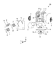
- FIG. 1 is an exploded perspective view showing a ventilation fan 100 according to the first embodiment.
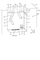
- FIG. 2 is a perspective view showing an assembled state of the ventilation fan 100 shown in FIG. 1, and is a diagram showing a state in which the ventilation fan 100 is hung on a wall surface 30 of a building and installed.
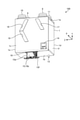
- FIG. 3 is a perspective view showing a state in which the control board 15 is pulled out of the housing 1 from the ventilation fan 100 shown in FIG.
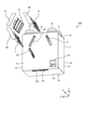
- FIG. 4 is a perspective view showing a state in which the filters 5, 6 and 7 and the filter lids 20, 21 and 22 are removed from the ventilation fan 100 shown in FIG. As shown in FIG.
- the ventilation fan 100 includes a housing 1, a heat exchange element 2, an air supply blower 3, an exhaust blower 4, an outside air filter 5, an exhaust filter 6, and an air supply filter 7. To prepare for. Further, the ventilation fan 100 includes an outdoor suction unit 8, an indoor suction unit 9, an indoor side outlet 10, an outdoor outlet 11, a drain pan 12, a drain port 13, an operation unit 14, and a control board. It is equipped with 15. The ventilation fan 100 is a device that ventilates the room while exchanging heat between the air from the outside and the air from the room. As shown in FIG. 2, the ventilation fan 100 is hung on the wall surface 30 of the building near the ceiling surface 31 and installed.
- the depth direction of the ventilation fan 100 is the X-axis direction
- the height direction of the ventilation fan 100 is the Y-axis direction
- the width direction of the ventilation fan 100 is the Z-axis direction.
- the + X-axis direction is the front
- the ⁇ X-axis direction is the rear.
- the + Y-axis direction is upward
- the ⁇ Y-axis direction is downward.
- the + Z axis direction is to the left and the ⁇ Z axis direction is to the right.
- the housing 1 is a box-shaped member constituting the outer shell of the ventilation fan 100.
- the shape of the housing 1 may be a cube, but in the present embodiment, it is a rectangular parallelepiped.
- the housing 1 has a top plate 1a, a bottom plate 1b, a front plate 1c, a back plate 1d, a left side plate 1e, and a right side plate 1f.
- the plate portion of the housing 1 in contact with the wall surface 30 is the back plate 1d
- the plate portion arranged on the opposite side of the back plate 1d from the wall surface 30 is the front plate 1c.
- the normal of the top plate 1a faces upward.
- the plan view shape of the top plate 1a is rectangular.
- the outdoor side suction portion 8, the indoor side suction portion 9, the indoor side blowout portion 10, and the outdoor side blowout portion 11 are provided on the top plate 1a.
- the outdoor suction unit 8 is a duct connection port for sucking air from the outside into the housing 1.
- a duct 27a connected to the outside is connected to the outdoor suction portion 8.
- the indoor suction unit 9 is a duct connection port for sucking air from the room into the housing 1.
- a duct 27b connected to the room is connected to the indoor suction portion 9.
- the indoor side blowing portion 10 is a duct connection port for blowing air from the outside to the outside of the housing 1.
- a duct 27c connected to the room is connected to the indoor side outlet portion 10.
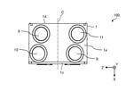
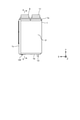
- FIG. 5 is a plan view of the ventilation fan 100 according to the first embodiment.
- the line extending in the direction perpendicular to the front plate 1c and the back plate 1d through the center of the top plate 1a in the Z-axis direction is referred to as the center line C.
- the indoor suction portion 9 and the indoor outlet 10 are arranged to the left of the center line C.
- the outdoor suction portion 8 and the outdoor outlet portion 11 are arranged to the right of the center line C.
- the outdoor suction portion 8 is arranged in front of the outdoor blowout portion 11.
- the indoor side blowing portion 10 is arranged in front of the indoor side suction portion 9.
- the outdoor suction portion 8 and the indoor blowout portion 10 are arranged at positions that coincide with each other in the X-axis direction.
- the indoor suction portion 9 and the outdoor blowout portion 11 are arranged at positions that coincide with each other in the X-axis direction.
- FIG. 7 is a front view of the ventilation fan 100 according to the first embodiment.
- the normal of the front plate 1c faces the front, which is the front.
- the front plate 1c connects the front ends of the top plate 1a and the bottom plate 1b to each other.
- the front view shape of the front plate 1c is rectangular.
- the front plate 1c is formed with an outside air filter opening 17, an exhaust filter opening 18, and an air supply filter opening 19 that communicate the inside and the outside of the housing 1. Has been done.
- FIG. 9 is a right side view of the ventilation fan 100 according to the first embodiment.
- the normal of the right plate 1f faces to the right.
- the right side plate 1f connects the right end portions of the top plate 1a and the bottom plate 1b to each other.
- the side view shape of the right side plate 1f is rectangular.
- the normal of the left plate 1e shown in FIG. 8 faces to the left.
- the left side plate 1e connects the left end portions of the top plate 1a and the bottom plate 1b to each other.
- the side view shape of the left side plate 1e is rectangular.
- FIG. 10 is a cross-sectional view taken along the line XX shown in FIG.
- the solid arrow X shown in FIG. 10 indicates the flow of air from the outside to the inside, that is, the flow of air supply.
- the broken line arrow Y shown in FIG. 10 indicates the flow of air from the room to the outside, that is, the flow of exhaust gas.
- the outdoor side suction portion 8 and the indoor side blowout portion 10 are not shown in cross section.
- an air supply air passage 23 for supplying air from the outside to the room and an exhaust air passage 24 for exhausting the air from the room to the outside are formed inside the housing 1, an air supply air passage 23 for supplying air from the outside to the room and an exhaust air passage 24 for exhausting the air from the room to the outside are formed.
- the air supply air passage 23 is an air passage that takes in outdoor air from the outdoor suction portion 8 into the housing 1 and supplies air from the indoor side outlet portion 10 toward the room.
- the exhaust air passage 24 is an air passage that takes in indoor air from the indoor side suction portion 9 into the housing 1 and exhausts it from the outdoor outlet portion 11 toward the outdoor side.
- the upstream side and the downstream side are based on the flow direction of the air flowing through the supply air passage 23 or the exhaust air passage 24.
- an outside air filter 5, a heat exchange element 2, and an air supply air blower 3 are arranged in order from the upstream side.
- a part of the air supply air passage 23 is formed of the heat insulating component 25 shown in FIG. 1 in order to suppress the occurrence of dew condensation.
- an exhaust filter 6, a heat exchange element 2, and an exhaust blower 4 are arranged in order from the upstream side.
- a part of the exhaust air passage 24 is formed of the heat insulating component 25 shown in FIG. 1 in order to suppress the occurrence of dew condensation.
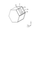
- FIG. 11 is a perspective view showing the heat exchange element 2 of the ventilation fan 100 according to the first embodiment.
- the shape of the heat exchange element 2 is not particularly limited as long as it is a polygonal column, but in the present embodiment, it is a hexagonal column.
- the heat exchange element 2 includes a plurality of partition members 2a arranged at intervals from each other, and a plurality of interval holding members 2b for maintaining the distance between the partition members 2a.
- the partition member 2a is formed in the form of a flatly processed sheet.
- the partition member 2a and the spacing member 2b are alternately laminated.
- An air passage is formed between the adjacent partition members 2a.
- the heat exchange element 2 is provided with air passages through which air from the outside flows and air passages through which air from the inside of the room flows alternately.
- the stacking direction which is the direction in which the partition member 2a and the spacing member 2b are laminated, coincides with the X-axis direction in the present embodiment, and is the direction perpendicular to the front plate 1c and the back plate 1d.
- the stacking direction may be a direction that coincides with the Y-axis direction and is perpendicular to the top plate 1a and the bottom plate 1b, or may be a direction that coincides with the Z-axis direction and is perpendicular to the left side plate 1e and the right side plate 1f.
- the heat exchange element 2 may be configured to be capable of both sensible heat exchange and latent heat exchange, or to be configured to be capable of either sensible heat exchange or latent heat exchange. May be good.
- the drain pan 12 is a member that is arranged below the heat exchange element 2 in the housing 1 and collects the drain water generated in the housing 1.
- the drain pan 12 is arranged on the bottom plate 1b.
- the control board 15 is arranged in the space 29 below the heat exchange element 2.
- the control board 15 is electrically connected to the operation unit 14 shown in FIG. 1 by a cable (not shown).
- the control board 15 has a first board 15a and a second board 15b.
- the first substrate 15a is a substrate connected to a power source (not shown).
- the first substrate 15a is housed in a box-shaped first substrate case 15c that opens downward.
- the second substrate 15b is a substrate having a connection unit, a control setting unit, and the like to which a sensor (not shown) is connected.
- the sensor connected to the second substrate 15b is, for example, a humidity sensor or a CO 2 sensor.
- the second substrate 15b is attached to the second substrate case 15d.
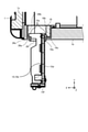
- FIG. 12 is a cross-sectional view taken along the line XII-XII shown in FIG.
- a rib 15e projecting forward or backward is formed at the upper end of the second substrate case 15d.
- a substrate lid 15f is attached to the lower end of the second substrate case 15d. When the second substrate case 15d and the second substrate 15b are inserted into the housing 1, the substrate lid 15f covers the substrate opening 16.
- the position fixing frame 26 is fitted in the opening 16 for the board.
- the positioning frame 26 has a first frame portion 26a, a second frame portion 26b, and a contact portion 26c.
- the first frame portion 26a is a square frame-shaped portion fitted into the first wall portion 16a.
- the second frame portion 26b is a square frame-shaped portion fitted into the second wall portion 16b.
- the opening area of the second frame portion 26b is larger than the opening area of the first frame portion 26a.
- the contact portion 26c is a flat portion connecting the upper end portion of the first frame portion 26a and the lower end portion of the second frame portion 26b.
- the contact portion 26c is arranged on the connecting wall portion 16c.
- the motor 32 is a device that rotates the blade 51.
- the type of the motor 32 is not particularly limited, but is, for example, a DC brushless motor.
- the motor 32 includes a motor housing 33, a stator 36, a rotor 37, a shaft 38, a first bearing 39, a second bearing 40, a circuit board 41, a protective cover 43, and a protective case 44. To prepare for.
- the direction parallel to the central axis P of the motor 32 is the axial direction
- the direction orthogonal to the central axis P of the motor 32 is the radial direction
- the central axis P of the motor 32 is referred to.
- the direction of rotation around the center is the circumferential direction.
- the axial and x m-axis direction a direction orthogonal to the x m-axis direction and y m-axis direction, a direction orthogonal to the x m-axis direction and the y m-axis direction and z m-axis direction.
- y m-axis direction is one direction orthogonal to the x m-axis direction, a direction included in the radial direction.
- z m-axis direction is one direction orthogonal to the x m-axis direction, a direction included in the radial direction.
- the motor housing 33 is a hollow member that houses the stator 36, the rotor 37, the first bearing 39, the second bearing 40, and the circuit board 41.
- the motor housing 33 has a frame 34 and a bracket 35.
- the material of the frame 34 and the bracket 35 is metal.
- Each of the frame 34 and the bracket 35 is formed in a bottomed cylindrical shape in which one end is opened along the xm axis direction.
- the frame 34 and the bracket 35 are arranged so that the openings face each other.
- a flange-shaped frame flange 34a extending radially outward is formed at the opening edge of the frame 34.
- a flange-shaped bracket flange 35a extending radially outward is formed at the opening edge of the bracket 35.
- the frame flange 34a and the bracket flange 35a are fixed to each other with screws 49 and 50 in a state of being overlapped with each other.
- a first bearing housing 34b for holding the first bearing 39 is formed on the bottom wall of the frame 34.
- An insertion hole 34c through which the shaft 38 is inserted is formed in the bottom wall of the frame 34 radially inside the first bearing housing 34b.
- a second bearing housing 35b for holding the second bearing 40 is formed on the bottom wall of the bracket 35.
- a first through hole 35c for pulling out the lead wire 42 to the outside of the motor housing 33 is formed on the side wall of the bracket 35.
- the first through hole 35c is formed so as to penetrate a part of the side wall including the bracket flange 35a.
- the stator 36 is a cylindrical member arranged inside the motor housing 33.
- the stator 36 is press-fitted into the frame 34 and the bracket 35.
- the stator 36 has an iron core 36a and a coil 36b wound around the iron core 36a.
- the rotor 37 is a cylindrical member arranged inside the stator 36.
- the rotor 37 rotates about the shaft 38.
- a gap (not shown) is provided between the stator 36 and the rotor 37 over the entire circumference.
- the shaft 38 is a member connected to the rotor 37. Although the shaft 38 is integrally formed with the rotor 37 in this embodiment, it may be formed separately from the rotor 37.
- One end 38a along the axial direction of the shaft 38 projects to the outside of the motor housing 33 through the insertion hole 34c.
- a blade 51 is attached to one end 38a of the shaft 38.
- the other end 38b along the axial direction of the shaft 38 is located inside the bracket 35.
- the circuit board 41 is a board that is arranged inside the motor housing 33 and controls the rotor 37.
- the circuit board 41 is arranged in a space formed between the rotor 37 and the bottom wall of the bracket 35. Power is supplied to the circuit board 41 via the lead wire 42.
- the lead wire 42 is connected to a circuit board 41 and an external power supply (not shown).
- the lead wire 42 passes through the first through hole 35c formed in the side wall of the bracket 35 and is pulled out to the outside of the motor housing 33.
- the plurality of lead wires 42 are covered with a tubular lead tube 45. Thereby, the lead wire 42 can be protected.
- the lead wire 42 means the lead wire 42 in a state of being covered with the lead tube 45.
- the base portion 44a is a portion separated from the protective cover 43.
- a space 46 is provided between the base 44a and the protective cover 43.
- the space 46 is filled with a sealing material 47.
- the sealing material 47 is, for example, a waterproof resin.
- a third through hole 44d through which the lead wire 42 can pass is formed in the base portion 44a.
- the lead wire 42 passes through the first through hole 35c, the second through hole 43a, and the third through hole 44d, and is led out to the outside of the motor housing 33.
- the first through hole 35c, the second through hole 43a, and the third through hole 44d are holes, notches, and the like.
- the third through hole 44d is provided at one end of the base 44a along the xm axis direction.
- Third through hole 44d is open to one along the x m-axis direction.
- the base portion 44a is formed with a holding projection 44e that projects inward from the inner wall of the third through hole 44d to hold the lead wire 42.
- the portion of the third through hole 44d in which the holding protrusion 44e is formed has the narrowest opening width.
- the opening width of the holding protrusion 44e is smaller than the diameter of the lead tube 45.
- confirmation holes 44f that can confirm the filling amount of the sealing material 47 in the space 46 are formed one by one.
- the shape of the confirmation hole 44f which is the internal confirmation portion, is not particularly limited, but is generally oval in the present embodiment.
- bent portion 44g is formed. As shown in FIG. 13, the bent portion 44g is bent so as to be located radially inwardly toward the other from the one along the x m-axis direction. The tip of the bent portion 44 g is in contact with the bottom wall of the bracket 35. As shown in FIG.
- the bent portion 44g is formed with a filling hole 44h for filling the space 46 with the sealing material 47.
- the shape of the filling hole 44h is not particularly limited, but is U-shaped in the present embodiment.
- Fill hole 44h is opened at the other along the x m-axis direction of the bent portion 44 g.
- Fill hole 44h, in the x m-axis direction, are formed on the opposite side of the third through hole 44d and the confirmation holes 44f.
- fill hole 44h, the second through-hole 43a it is disposed on the -x m side of the x m-axis than the third through hole 44d and the confirmation holes 44f.
- the second through-hole 43a is disposed on the -x m side of the x m-axis than the third through hole 44d and the confirmation holes 44f.
- the two contact portions 44b are portions that can contact the side wall of the bracket 35.
- the contact portion 44b extends parallel to the base portion 44a.
- the base portion 44a is separated from the protective cover 43 in a state where the contact portion 44b is in contact with the side wall of the bracket 35.
- the protective case flange 44c extends along the y m-axis direction from one end along the x m-axis direction of the base portion 44a and contact portion 44b.
- the protective case flange 44c is formed with a screw notch 44i for passing a screw 49, which will be described later.
- the motor 32 is fixed to the rectangular frame-shaped motor fixing portion 48 with screws 49 and 50.
- the motor 32 is arranged inside the motor fixing portion 48.
- a flange 48a on the motor fixing portion side that supports the motor 32 is formed on the inner surface of the motor fixing portion 48 facing the motor 32.
- the motor fixing portion side flange 48a is formed in an arc shape along the outer peripheral shape of the motor housing 33.
- the protective case flange 44c, the frame flange 34a, the bracket flange 35a, and the motor fixing portion side flange 48a are co-tightened with screws 49 in a state of being overlapped with each other.
- the protective case 44 is fixed to the frame flange 34a, the bracket flange 35a, and the motor fixing portion side flange 48a. Further, in the position where the protective case flange 44c does not exist, the frame flange 34a, the bracket flange 35a, and the motor fixing portion side flange 48a are co-tightened with screws 50 in a state of being overlapped with each other.
- a first through hole 35c for pulling out the lead wire 42 to the outside of the motor housing 33 is formed on the side wall of the bracket 35.
- the motor 32 has a protective cover 43 which is attached so as to cover the first through hole 35c and has a second through hole 43a through which the lead wire 42 can pass, and a third through hole 43a through which the lead wire 42 can pass.
- the through hole 44d is formed and includes a protective cover 43 and a protective case 44 that covers the lead wire 42. Further, a space 46 is provided between the protective case 44 and the protective cover 43, and the space 46 is filled with the sealing material 47.
- the sealing material 47 can prevent moist air from entering the inside of the motor 32 through the third through hole 44d and the first through hole 35c. Therefore, dew condensation is less likely to occur inside the motor 32. Therefore, the ventilation fan 100 provided with the motor 32 can be used for ventilation in a high humidity atmosphere.
- the high humidity atmosphere is, for example, the air in the bathroom.
- the nozzle of the container 52 in which the sealing material 47 made of waterproof resin is sealed is positioned in the filling hole 44h, and the sealing material 47 is placed in the space 46 from the container 52 through the filling hole 44h.
- the motor 32 is arranged so as to be. Further, when the sealing material 47 is filled, as shown in FIG. 18, the position of the second through hole 43a in the vertical direction is higher than the positions of the third through hole 44d and the confirmation hole 44f in the vertical direction.
- the motor 32 shown in FIG. 17 is arranged.
- the first through hole 35c shown in FIG. 18 is largely closed by the protective cover 43 and the lead wire 42, but is shown in FIG. 14 in order to allow the lead wire 42 to pass through the second through hole 43a of the protective cover 43.
- the inner diameter of the second through hole 43a is formed to be slightly larger than the outer diameter of the lead wire 42. As a result, a fine gap is formed between the inner wall of the second through hole 43a and the outer peripheral surface of the lead wire 42.
- a confirmation hole 44f is provided in the present embodiment, and when the sealing material 47 is filled, the confirmation hole 44f is provided.
- the protective case 44 is formed with a filling hole 44h for filling the space 46 with the sealing material 47, so that the container for filling the sealing material 47 is formed. Since the alignment of the nozzles of the 52 is facilitated, the workability when filling the sealing material 47 can be improved. Further, in the present embodiment, as shown in FIG. 17, the protective case 44 is formed with a confirmation hole 44f at which the filling amount of the sealing material 47 can be confirmed, so that the filling work of the sealing material 47 is stopped. It becomes easy to determine the timing of the sealing material 47, and the filling amount of the sealing material 47 can be adjusted to an appropriate amount.
- the protective case 44 is formed with a holding protrusion 44e that protrudes from the inner wall of the third through hole 44d and holds the lead wire 42, whereby the lead wire 42 is formed. Can be fixed.
- the movement of the lead wire 42 can be suppressed until the liquid sealing material 47 filled in the third through hole 44d is solidified, so that a gap is unlikely to occur between the lead wire 42 and the sealing material 47. Therefore, since moist air can be further prevented from entering the inside of the motor 32, dew condensation is less likely to occur inside the motor 32. Further, since the movement of the lead wire 42 can be suppressed until the liquid sealing material 47 filled in the third through hole 44d is solidified, the workability when filling the sealing material 47 can be improved.
- the sealing material 47 shown in FIG. 13 is a waterproof resin, it is possible to further prevent moist air from entering the inside of the motor 32, so that dew condensation is further generated inside the motor 32. It becomes difficult to do.
- the protective case 44 shown in FIG. 13 is an integral body, the arrangement of the protective case 44, the protective cover 43, and the lead wire 42 can be easily determined, so that the assembly work is easy. Become.
- the confirmation hole 44f is provided as a means for confirming the filling amount of the sealing material 47, but a part or all of the protective case 44 is made transparent or translucent, and the inside of the protective case 44 is made transparent or translucent. You may be able to confirm.
- the transparent portion or the translucent portion of the protective case 44 serves as an internal confirmation portion where the filling amount of the sealing material 47 can be confirmed.
- the protective case 44 is fixed to the frame flange 34a, the bracket flange 35a, and the motor fixing portion side flange 48a with screws 49, but the fixing location of the protective case 44. It is not intended to limit.
- the protective case 44 may be fixed only to the frame 34 or may be fixed only to the bracket 35.
- screw holes are provided in the contact portion 44b of the protective case 44 shown in FIG. 17 that comes into contact with the side wall of the bracket 35 and the side wall of the bracket 35. Screws can be screwed into both screw holes.
- the configuration shown in the above embodiment is an example, and can be combined with another known technique, or a part of the configuration may be omitted or changed without departing from the gist. It is possible.
Landscapes
- Engineering & Computer Science (AREA)
- Power Engineering (AREA)
- Motor Or Generator Frames (AREA)
Abstract
モータ(32)は、フレーム(34)とブラケット(35)とを有するモータ筐体(33)と、ステータ(36)と、ロータ(37)と、シャフト(38)と、回路基板(41)とを備える。ブラケット(35)の側壁には、第1の貫通孔(35c)が形成されている。モータ(32)は、第1の貫通孔(35c)を覆うようにブラケット(35)に取り付けられてリード線(42)が通過可能な第2の貫通孔(43a)が形成された保護カバー(43)と、保護カバー(43)およびリード線(42)を覆う保護ケース(44)とを備える。保護カバー(43)と保護ケース(44)との間には、空間(46)が設けられている。空間(46)には、シール材(47)が充填されている。保護ケース(44)には、リード線(42)が通過可能な第3の貫通孔(44d)と、第3の貫通孔(44d)の内壁から突出してリード線(42)を保持する保持突起とが形成されている。
Description
本開示は、回路基板を内蔵するモータ、および、モータを備える換気扇に関する。
従来、換気扇のモータには、回路基板を内蔵するモータが用いられることがある。例えば、特許文献1には、回路基板、ステータ、ロータなどを筐体の内部に収容したモータが開示されている。回路基板には、回路基板に電源を供給するリード線が接続されている。筐体には、リード線を筐体の外部に引き出すための孔が形成されている。
特許文献1に開示されたモータが搭載された換気扇を、浴室などの高湿度雰囲気に設置する場合がある。このような場合には、換気扇が湿った空気を吸い込むと、湿った空気が孔を通じて筐体の内部に侵入することで筐体の内部に結露が発生し、結露水が回路基板に付着するとショートするおそれがある。そのため、シール材で孔を塞ぐ必要がある。一般的には、液状のシール材を孔に充填して、シール材を固化させることで孔を塞ぐ方法が採られている。
しかし、特許文献1に開示された技術では、孔に通されたリード線を固定する手段が何ら設けられていないため、孔に充填した液状のシール材が固化するまでリード線の動きを抑制できず、リード線とシール材との間に隙間が生じる可能性がある。これにより、湿った空気が隙間を通じて筐体の内部に侵入して、筐体の内部に結露が発生する可能性がある。
本開示は、上記に鑑みてなされたものであって、モータの内部に結露が発生し難いモータを得ることを目的とする。
上述した課題を解決し、目的を達成するために、本開示にかかるモータは、開口が設けられた有底筒状に形成されてフレームフランジが開口縁部に設けられたフレームと、開口が設けられた有底筒状に形成されてフレームフランジに重ね合わされるブラケットフランジが開口縁部に設けられたブラケットとを有するモータ筐体と、モータ筐体の内部に配置された筒形状のステータと、ステータの内側に配置されたロータと、ロータに連結されたシャフトと、モータ筐体の内部に配置されてロータを制御し、リード線を介して電源が供給される回路基板と、を備える。ブラケットの側壁には、リード線をモータ筐体の外部に引き出すための第1の貫通孔が形成されている。モータは、第1の貫通孔を覆うようにブラケットに取り付けられてリード線が通過可能な第2の貫通孔が形成された保護カバーと、保護カバーおよびリード線を覆う保護ケースと、を備える。保護カバーと保護ケースとの間には、空間が設けられている。空間には、シール材が充填されている。保護ケースには、リード線が通過可能な第3の貫通孔と、第3の貫通孔の内壁から突出してリード線を保持する保持突起とが形成されている。
本開示にかかるモータでは、モータの内部に結露が発生し難いという効果を奏する。
以下に、実施の形態にかかるモータおよび換気扇を図面に基づいて詳細に説明する。
実施の形態1.
図1は、実施の形態1にかかる換気扇100を示す分解斜視図である。図2は、図1に示された換気扇100の組付状態を示す斜視図であって、換気扇100が建物の壁面30に掛けられて設置された状態を示す図である。図3は、図2に示された換気扇100から制御基板15を筐体1外に引き出した状態を示す斜視図である。図4は、図2に示された換気扇100から各フィルター5,6,7および各フィルター用蓋20,21,22を取り外した状態を示す斜視図である。図1に示すように、換気扇100は、筐体1と、熱交換素子2と、給気用送風機3と、排気用送風機4と、外気フィルター5と、排気フィルター6と、給気フィルター7とを備える。また、換気扇100は、室外側吸込部8と、室内側吸込部9と、室内側吹出部10と、室外側吹出部11と、ドレンパン12と、ドレン口13と、操作部14と、制御基板15とを備える。換気扇100は、室外からの空気と室内からの空気との間で熱交換させながら室内の換気を行う装置である。図2に示すように、換気扇100は、建物の壁面30において天井面31付近に掛けられて設置されている。以下、換気扇100の奥行方向をX軸方向とし、換気扇100の高さ方向をY軸方向とし、換気扇100の幅方向をZ軸方向とする。また、+X軸方向を前方、-X軸方向を後方とする。また、+Y軸方向を上方、-Y軸方向を下方とする。また、+Z軸方向を左方、-Z軸方向を右方とする。
図1は、実施の形態1にかかる換気扇100を示す分解斜視図である。図2は、図1に示された換気扇100の組付状態を示す斜視図であって、換気扇100が建物の壁面30に掛けられて設置された状態を示す図である。図3は、図2に示された換気扇100から制御基板15を筐体1外に引き出した状態を示す斜視図である。図4は、図2に示された換気扇100から各フィルター5,6,7および各フィルター用蓋20,21,22を取り外した状態を示す斜視図である。図1に示すように、換気扇100は、筐体1と、熱交換素子2と、給気用送風機3と、排気用送風機4と、外気フィルター5と、排気フィルター6と、給気フィルター7とを備える。また、換気扇100は、室外側吸込部8と、室内側吸込部9と、室内側吹出部10と、室外側吹出部11と、ドレンパン12と、ドレン口13と、操作部14と、制御基板15とを備える。換気扇100は、室外からの空気と室内からの空気との間で熱交換させながら室内の換気を行う装置である。図2に示すように、換気扇100は、建物の壁面30において天井面31付近に掛けられて設置されている。以下、換気扇100の奥行方向をX軸方向とし、換気扇100の高さ方向をY軸方向とし、換気扇100の幅方向をZ軸方向とする。また、+X軸方向を前方、-X軸方向を後方とする。また、+Y軸方向を上方、-Y軸方向を下方とする。また、+Z軸方向を左方、-Z軸方向を右方とする。
筐体1は、換気扇100の外殻を構成する箱状の部材である。筐体1の形状は、立方体状でもよいが、本実施の形態では直方体状である。筐体1は、天板1aと、底板1bと、正面板1cと、背板1dと、左側板1eと、右側板1fとを有する。本実施の形態では、筐体1のうち壁面30に接する板部を背板1dとし、背板1dを挟んで壁面30と反対側に配置される板部を正面板1cとする。
天板1aの法線は、上方を向く。天板1aの平面視形状は、矩形である。室外側吸込部8、室内側吸込部9、室内側吹出部10および室外側吹出部11は、天板1aに設けられている。室外側吸込部8は、室外からの空気を筐体1内に吸い込むためのダクト接続口である。室外側吸込部8には、室外に繋がるダクト27aが接続される。室内側吸込部9は、室内からの空気を筐体1内に吸い込むためのダクト接続口である。室内側吸込部9には、室内に繋がるダクト27bが接続される。室内側吹出部10は、室外からの空気を筐体1外へ吹き出すためのダクト接続口である。室内側吹出部10には、室内に繋がるダクト27cが接続される。室外側吹出部11は、室内からの空気を筐体1外へ吹き出すためのダクト接続口である。室外側吹出部11には、室外に繋がるダクト27dが接続される。天板1aの上には、室外側吸込部8、室内側吸込部9、室内側吹出部10、室外側吹出部11および各ダクト27a,27b,27c,27dを隠すための意匠材28が配置されている。
図5は、実施の形態1にかかる換気扇100の平面図である。ここで、天板1aのZ軸方向の中心を通って正面板1cおよび背板1dと垂直方向に延びる線を中心線Cとする。室内側吸込部9と室内側吹出部10は、中心線Cよりも左方に配置されている。室外側吸込部8と室外側吹出部11は、中心線Cよりも右方に配置されている。室外側吸込部8は、室外側吹出部11の前方に配置されている。室内側吹出部10は、室内側吸込部9の前方に配置されている。室外側吸込部8と室内側吹出部10とは、X軸方向において一致する位置に配置されている。室内側吸込部9と室外側吹出部11とは、X軸方向において一致する位置に配置されている。
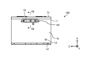
図6は、実施の形態1にかかる換気扇100の底面図である。底板1bの法線は、下方を向く。底板1bの底面視形状は、矩形である。底板1bは、天板1aの下方に天板1aから離れて配置されている。底板1bには、筐体1の内部と外部とを連通する基板用開口部16が形成されている。基板用開口部16は、筐体1外への制御基板15の引き出しおよび筐体1内への制御基板15の差し込みを行うための開口である。下方から見た基板用開口部16の形状は、矩形である。基板用開口部16は、底板1bのX軸方向の中心よりも前方に配置されている。基板用開口部16は、本実施の形態では底板1bのうち正面板1cとの境界部の近くに配置されている。底板1bには、ドレン口13が設けられている。ドレン口13は、本実施の形態では底板1bの右後隅部の近くに配置されている。
図7は、実施の形態1にかかる換気扇100の正面図である。正面板1cの法線は、正面となる前方を向く。正面板1cは、天板1aと底板1bとの前端部同士を繋いでいる。正面板1cの正面視形状は、矩形である。図4および図7に示すように、正面板1cには、筐体1の内部と外部とを連通する外気フィルター用開口部17、排気フィルター用開口部18および給気フィルター用開口部19が形成されている。
外気フィルター用開口部17は、筐体1内への外気フィルター5の取り付けおよび筐体1外への外気フィルター5の取り出しを行うための開口である。外気フィルター用開口部17は、正面板1cのZ軸方向の中心よりも右方に配置されている。前方から見た外気フィルター用開口部17の形状は、長方形である。外気フィルター用開口部17は、上方から下方に向かうほど右側板1fに近付くように傾斜している。外気フィルター用蓋20は、着脱により開閉可能である。外気フィルター用蓋20は閉じているときに外気フィルター用開口部17を覆う。正面板1cのうち外気フィルター用開口部17よりも下方には、換気扇100の運転開始、停止などを操作するための操作部14が設けられている。操作部14は、本実施の形態では正面板1cの右下隅部の近くに配置されている。
排気フィルター用開口部18は、筐体1内への排気フィルター6の取り付けおよび筐体1外への排気フィルター6の取り出しを行うための開口である。排気フィルター用開口部18は、正面板1cのZ軸方向の中心よりも左方に配置されており、外気フィルター用開口部17と同じ高さ位置に設けられている。前方から見た排気フィルター用開口部18の形状は、長方形である。排気フィルター用開口部18は、上方から下方に向かうほど左側板1eに近付くように傾斜している。排気フィルター用蓋21は、着脱により開閉可能である。排気フィルター用蓋21は閉じているときに排気フィルター用開口部18を覆う。
給気フィルター用開口部19は、筐体1内への給気フィルター7の取り付けおよび筐体1外への給気フィルター7の取り出しを行うための開口である。給気フィルター用開口部19は、正面板1cのZ軸方向の中心よりも左方に配置されており、排気フィルター用開口部18の下方に配置されている。前方から見た給気フィルター用開口部19の形状は、長方形である。給気フィルター用開口部19は、上方から下方に向かうほど右側板1fに近付くように傾斜している。給気フィルター用蓋22は、着脱により開閉可能である。給気フィルター用蓋22は閉じているときに給気フィルター用開口部19を覆う。
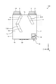
図8は、実施の形態1にかかる換気扇100の背面図である。背板1dの法線は、後方を向く。背板1dは、天板1aと底板1bとの後端部同士を繋いでいる。背板1dの背面視形状は、矩形である。
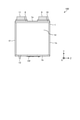
図9は、実施の形態1にかかる換気扇100の右側面図である。右側板1fの法線は、右方を向く。右側板1fは、天板1aと底板1bとの右端部同士を繋いでいる。右側板1fの側面視形状は、矩形である。図8に示す左側板1eの法線は、左方を向く。左側板1eは、天板1aと底板1bとの左端部同士を繋いでいる。左側板1eの側面視形状は、矩形である。
図10は、図9に示されたX-X線に沿った断面図である。図10に示す実線の矢印Xは、室外から室内に向かう空気の流れ、すなわち給気の流れを示している。図10に示す破線の矢印Yは、室内から室外に向かう空気の流れ、すなわち排気の流れを示している。なお、図10では、説明の容易化のために、室外側吸込部8、室内側吹出部10を断面にしていない。筐体1内には、室外からの空気を室内に給気するための給気風路23と、室内からの空気を室外に排気するための排気風路24とが形成されている。給気風路23は、室外空気を室外側吸込部8から筐体1内に取り入れて、室内側吹出部10から室内に向けて給気する風路である。排気風路24は、室内空気を室内側吸込部9から筐体1内に取り入れて室外側吹出部11から室外に向けて排気する風路である。以下、上流側、下流側とは、給気風路23または排気風路24を流れる空気の流れ方向を基準とする。
給気風路23には、上流側から順に、外気フィルター5と熱交換素子2と給気用送風機3とが配置されている。給気風路23の一部は、結露の発生を抑制するために、図1に示す断熱部品25で形成されている。
排気風路24には、上流側から順に、排気フィルター6と熱交換素子2と排気用送風機4とが配置されている。排気風路24の一部は、結露の発生を抑制するために、図1に示す断熱部品25で形成されている。
熱交換素子2は、給気風路23内を流れる室外空気と排気風路24内を流れる室内空気との間で熱交換させる部材である。熱交換素子2は、筐体1内において、天板1aと台座12aとの間に設置されている。台座12aと底板1bとの間には、制御基板15を収容するためのスペース29が形成されている。熱交換素子2は、筐体1のZ軸方向の中央に配置されている。熱交換素子2は、本実施の形態ではX軸方向に対し水平状態、Z軸方向に対して傾いた状態で設置されているが、いずれの方向に対しても水平または傾いた状態で設置されてもよい。
図11は、実施の形態1にかかる換気扇100の熱交換素子2を示す斜視図である。熱交換素子2の形状は、多角柱であれば特に制限されないが、本実施の形態では六角柱である。熱交換素子2は、互いに間隔を空けて配置される複数の仕切部材2aと、仕切部材2a同士の間隔を保持する複数の間隔保持部材2bとを備える。仕切部材2aは、平坦に加工されたシート状に形成されている。仕切部材2aと間隔保持部材2bとは、交互に積層されている。隣り合う仕切部材2aの間には、風路が形成されている。熱交換素子2には、室外からの空気が流れる風路と、室内からの空気が流れる風路とが交互に設けられている。熱交換素子2は、本実施の形態では室外からの空気の流れ方向と室内からの空気の流れ方向とが互いに対向する対向流型の熱交換素子であるが、室外からの空気の流れ方向と室内からの空気の流れ方向とが直交する直交流型の熱交換素子でもよい。
仕切部材2aと間隔保持部材2bとを積層させた方向である積層方向は、本実施の形態ではX軸方向と一致しており、正面板1cおよび背板1dと垂直な方向である。なお、積層方向は、Y軸方向と一致して天板1aおよび底板1bと垂直な方向でもよいし、Z軸方向と一致して左側板1eおよび右側板1fと垂直な方向でもよい。仕切部材2aの材料を適宜変更することで、熱交換素子2を、顕熱交換および潜熱交換の両方を行える構成にしてもよいし、顕熱交換および潜熱交換のいずれか一方を行える構成にしてもよい。
図10に示すように、給気用送風機3は、給気風路23内に配置される送風機である。給気用送風機3は、室外側吸込部8から給気風路23内に空気を取り込み、室内側吹出部10から空気を室内へ向けて送風する。給気用送風機3は、熱交換素子2、外気フィルター5および給気フィルター7よりも下流側に配置されている。
排気用送風機4は、排気風路24内に配置される送風機である。排気用送風機4は、室内側吸込部9から排気風路24内に空気を取り込み、室外側吹出部11から空気を室外へ向けて送風する。排気用送風機4は、排気フィルター6および熱交換素子2よりも下流側に配置されている。給気用送風機3および排気用送風機4のそれぞれは、モータ32を備える。モータ32は、給気用送風機3と排気用送風機4とで同じ構成である。モータ32の詳細については後述する。
外気フィルター5は、給気風路23内に配置されて、室外からの空気中に含まれる塵埃、虫などの異物を捕集する部材である。外気フィルター5は、室外側吸込部8よりも下流側で、熱交換素子2よりも上流側に配置されている。外気フィルター5は、熱交換素子2における室外空気の流入口に配置されている。外気フィルター5で塵埃を捕集することによって、塵埃の付着による熱交換素子2の目詰まりを抑制することができる。外気フィルター5は、筐体1のZ軸方向の中心よりも右方に配置されている。
給気フィルター7は、給気風路23内に配置されて、室外からの空気中に含まれる塵埃、虫などの異物を捕集する部材である。給気フィルター7は、熱交換素子2よりも下流側で、室内側吹出部10よりも上流側に配置されている。給気フィルター7は、熱交換素子2における室外空気の流出口に配置されている。給気風路23内に2枚の外気フィルター5および給気フィルター7を設けることによって、室外からの空気をより一層清浄にすることができる。給気フィルター7は、筐体1のZ軸方向の中心よりも左方に配置されている。
排気フィルター6は、排気風路24内に配置されて、室内からの空気中に含まれる塵埃、虫などの異物を捕集する部材である。排気フィルター6は、室内側吸込部9よりも下流側で、熱交換素子2よりも上流側に配置されている。排気フィルター6は、熱交換素子2における室内空気の流入口に配置されている。排気フィルター6は、筐体1のZ軸方向の中心よりも左方に配置されている。
ドレンパン12は、筐体1内において熱交換素子2よりも下方に配置されて、筐体1内で発生したドレン水を溜める部材である。ドレンパン12は、底板1bの上に配置されている。
ドレン口13は、ドレンパン12に溜められたドレン水を筐体1外へ排出する部材である。ドレン口13は、Y軸方向に延びる円筒状に形成されている。ドレン口13は、底板1bおよびドレンパン12を貫通している。ドレン口13の下端部は、底板1bよりも下方に突出している。ドレン口13の上端部は、ドレンパン12の底面と同じ高さ位置に設けられている。本実施の形態では、ドレン口13はドレンパン12と一体に形成されている。
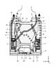
制御基板15は、熱交換素子2の下方において、スペース29内に配置されている。制御基板15は、図示しないケーブルで図1に示す操作部14と電気的に接続されている。図1に示すように、制御基板15は、第1基板15aと、第2基板15bとを有する。第1基板15aは、図示しない電源と接続される基板である。第1基板15aは、下方に開口する箱状の第1基板ケース15c内に収容される。第2基板15bは、図示しないセンサーが接続される接続部、制御設定部などを有する基板である。第2基板15bに接続されるセンサーは、例えば、湿度センサー、CO2センサーである。第2基板15bは、第2基板ケース15dに取り付けられている。
図12は、図6に示されたXII-XII線に沿った断面図である。第2基板ケース15dの上端部には、前方または後方に突出するリブ15eが形成されている。第2基板ケース15dの下端部には、基板用蓋15fが取り付けられている。第2基板ケース15dおよび第2基板15bが筐体1内に差し込まれたときに、基板用蓋15fは基板用開口部16を覆う。
底板1bには、第2基板15bを筐体1外へ引出可能な基板用開口部16が形成されている。基板用開口部16を通じて筐体1内から第2基板ケース15dおよび第2基板15bを下方に引き出すことによって、第2基板15bを筐体1外に露出させることができる。基板用開口部16の内壁には、第1壁部16aと、第2壁部16bと、連結壁部16cとが形成されている。第1壁部16aおよび第2壁部16bは、いずれも四角筒状に形成されている。第2壁部16bは、第1壁部16aよりも上方に配置される。第2壁部16bの開口面積は、第1壁部16aの開口面積よりも大きい。連結壁部16cは、第1壁部16aの上端部と第2壁部16bの下端部とを連結する平坦状の部分である。
基板用開口部16には、位置止め枠26が嵌め込まれている。位置止め枠26は、第1枠部26aと、第2枠部26bと、接触部26cとを有する。第1枠部26aは、第1壁部16aに嵌め込まれる四角枠状の部分である。第2枠部26bは、第2壁部16bに嵌め込まれる四角枠状の部分である。第2枠部26bの開口面積は、第1枠部26aの開口面積よりも大きい。接触部26cは、第1枠部26aの上端部と第2枠部26bの下端部とを繋ぐ平坦状の部分である。接触部26cは、連結壁部16cの上に配置されている。接触部26cは、第2基板15bが筐体1外に引き出された状態で、リブ15eに接触する。リブ15eと接触部26cとが互いに接触することで、筐体1内から引き出された第2基板ケース15dおよび第2基板15bが静止状態で保持される。リブ15eと接触部26cとは、筐体1外へ引き出された制御基板15を静止した状態で保持する保持部となる。
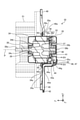
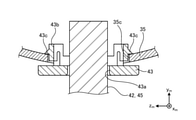
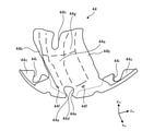
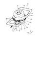
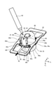
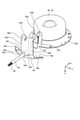
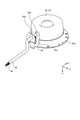
ここで、図13から図17を参照して、給気用送風機3および排気用送風機4のモータ32について説明する。図13は、実施の形態1におけるモータ32の断面図である。図14は、図13に示されたXIV-XIV線に沿った断面図である。図15は、実施の形態1におけるモータ32の保護ケース44を示す斜視図である。図16は、実施の形態1におけるモータ32の斜視図である。図17は、実施の形態1におけるモータ32にシール材47を充填している状態を示す斜視図である。図18は、実施の形態1におけるブラケット35、保護カバー43、保護ケース44、リード線42およびリードチューブ45を示す分解斜視図である。図19は、実施の形態1におけるブラケット35、保護カバー43、リード線42およびリードチューブ45を示す分解斜視図である。図13には、モータ32に取り付けられるブレード51を二点鎖線で図示している。
モータ32は、ブレード51を回転させる機器である。モータ32の種類は、特に限定されないが、例えば直流ブラシレスモータである。モータ32は、モータ筐体33と、ステータ36と、ロータ37と、シャフト38と、第1のベアリング39と、第2のベアリング40と、回路基板41と、保護カバー43と、保護ケース44とを備える。以下、モータ32の各構成要素について方向を説明するときには、モータ32の中心軸Pと平行な方向を軸方向、モータ32の中心軸Pと直交する方向を径方向、モータ32の中心軸Pを中心とする回転方向を周方向とする。また、軸方向をxm軸方向とし、xm軸方向と直交する方向をym軸方向とし、xm軸方向およびym軸方向と直交する方向をzm軸方向とする。ここで、ym軸方向は、xm軸方向に直交する1つの方向であり、径方向に含まれる方向である。また、zm軸方向は、xm軸方向に直交する1つの方向であり、径方向に含まれる方向である。
モータ筐体33は、ステータ36、ロータ37、第1のベアリング39、第2のベアリング40、回路基板41を収容する中空部材である。モータ筐体33は、フレーム34と、ブラケット35とを有する。フレーム34およびブラケット35の材料は、金属である。フレーム34およびブラケット35のそれぞれは、xm軸方向に沿った一方の端部が開口する有底円筒状に形成されている。フレーム34およびブラケット35は、互いに開口を向けて配置されている。フレーム34の開口縁部には、径方向外側に延びる鍔状のフレームフランジ34aが形成されている。ブラケット35の開口縁部には、径方向外側に延びる鍔状のブラケットフランジ35aが形成されている。フレームフランジ34aとブラケットフランジ35aとは、互いに重ね合わされた状態でネジ49,50で固定されている。
フレーム34の底壁には、第1のベアリング39を保持する第1のベアリングハウジング34bが形成されている。フレーム34の底壁のうち第1のベアリングハウジング34bよりも径方向内側には、シャフト38が挿通される挿通孔34cが形成されている。ブラケット35の底壁には、第2のベアリング40を保持する第2のベアリングハウジング35bが形成されている。図18および図19に示すように、ブラケット35の側壁には、リード線42をモータ筐体33の外部に引き出すための第1の貫通孔35cが形成されている。第1の貫通孔35cは、ブラケットフランジ35aを含む側壁の一部を貫通して形成されている。
図13に示すように、ステータ36は、モータ筐体33の内部に配置された円筒形状の部材である。ステータ36は、フレーム34およびブラケット35の内部に圧入されている。ステータ36は、鉄心36aと、鉄心36aに巻回されるコイル36bとを有する。
ロータ37は、ステータ36の内側に配置された円筒形状の部材である。ロータ37は、シャフト38を中心に回転する。ステータ36とロータ37との間には、図示しない隙間が全周に亘って設けられている。
シャフト38は、ロータ37に連結された部材である。シャフト38は、本実施の形態ではロータ37と一体に形成されているが、ロータ37と別体に形成されてもよい。シャフト38の軸方向に沿った一方の端部38aは、挿通孔34cを通じてモータ筐体33の外部に突出している。シャフト38の一方の端部38aには、ブレード51が取り付けられている。シャフト38の軸方向に沿った他方の端部38bは、ブラケット35の内部に配置されている。
第1のベアリング39および第2のベアリング40は、シャフト38を回転可能に支持する軸受である。第1のベアリング39と第2のベアリング40とは、xm軸方向でロータ37を挟んで配置されている。第1のベアリング39は、ロータ37よりもxm軸の+xm側に配置されている。第1のベアリング39は、環状の第1のベアリングハウジング34b内に保持されている。第1のベアリングハウジング34bは、フレーム34の底壁の一部をxm軸の-xm側に凸となるように屈曲させることで形成されている。第2のベアリング40は、ロータ37よりもxm軸の-xm側に配置されている。第2のベアリング40は、環状の第2のベアリングハウジング35b内に保持されている。第2のベアリングハウジング35bは、ブラケット35の一部をxm軸の+xm側に凸となるように屈曲させることで形成されている。
回路基板41は、モータ筐体33の内部に配置されて、ロータ37を制御する基板である。回路基板41は、ロータ37とブラケット35の底壁との間に形成される空間に配置されている。回路基板41には、リード線42を介して、電源が供給される。リード線42は、回路基板41と図示しない外部電源とに接続されている。リード線42は、ブラケット35の側壁に形成された第1の貫通孔35cを通過してモータ筐体33の外部に引き出される。複数本のリード線42は、筒状のリードチューブ45によって覆われている。これにより、リード線42を保護することができる。以下、リード線42とは、リードチューブ45に覆われた状態のリード線42のことを意味する。
保護カバー43は、リード線42を保護する板状の部材である。保護カバー43の材料は、例えば、樹脂である。保護カバー43は、第1の貫通孔35cを径方向外側から覆うようにブラケット35の側壁に取り付けられている。保護カバー43には、リード線42が通過可能な第2の貫通孔43aが形成されている。図14に示すように、保護カバー43には、第1の貫通孔35cに差し込まれる差込部43bが形成されている。差込部43bには、第1の貫通孔35cの縁に引っ掛けられる爪部43cが形成されている。差込部43bを径方向外側から第1の貫通孔35cに差し込んで、爪部43cを第1の貫通孔35cの縁に引っ掛けることにより、保護カバー43がブラケット35の側壁に固定されている。
図13に示すように、保護ケース44は、保護カバー43の全体およびリード線42の一部を径方向外側から覆う部材である。保護ケース44は、ブラケット35の側壁の一部およびブラケットフランジ35aの一部も覆っている。保護ケース44の材料は、例えば、樹脂である。図15に示すように、保護ケース44は、基部44aと、基部44aを挟んで両側に設けられた2つの接触部44bと、基部44aおよび接触部44bのxm軸方向に沿った一方の端部から直交する方向に延びる2つの保護ケースフランジ44cとを有する。
図13に示すように、基部44aは、保護カバー43から離隔する部分である。基部44aと保護カバー43との間には、空間46が設けられている。空間46には、シール材47が充填されている。シール材47は、例えば、防水樹脂である。基部44aには、リード線42が通過可能な第3の貫通孔44dが形成されている。リード線42は、第1の貫通孔35c、第2の貫通孔43aおよび第3の貫通孔44dを通過してモータ筐体33の外部に引き出されている。なお、第1の貫通孔35c、第2の貫通孔43aおよび第3の貫通孔44dは、孔、切欠きなどである。
図15に示すように、第3の貫通孔44dは、基部44aのxm軸方向に沿った一方の端部に設けられている。第3の貫通孔44dは、xm軸方向に沿った一方に開口している。基部44aには、第3の貫通孔44dの内壁から内向きに突出してリード線42を保持する保持突起44eが形成されている。第3の貫通孔44dのうち保持突起44eが形成された部分は、開口幅が最も狭くなっている。保持突起44eの開口幅は、リードチューブ45の直径よりも小さい。第3の貫通孔44dの内壁に保持突起44eを設けることにより、第3の貫通孔44dのxm軸方向に沿った一方の開口からリード線42が抜け出すことを防止できる。保持突起44eの数は、特に制限されないが、本実施の形態では2つである。2つの保持突起44eは、隙間を挟んで設けられている。
基部44aのうち第3の貫通孔44dを挟んだ両側には、空間46におけるシール材47の充填量を確認可能な確認孔44fが一つずつ形成されている。内部確認部である確認孔44fの形状は、特に制限されないが、本実施の形態では概ね長円形である。基部44aのxm軸方向に沿った他方の端部には、折曲部44gが形成されている。図13に示すように、折曲部44gは、xm軸方向に沿った一方から他方に向かうにつれて径方向内側に位置するように折り曲げられている。折曲部44gの先端部は、ブラケット35の底壁と接触している。図15に示すように、折曲部44gには、シール材47を空間46に充填するための充填孔44hが形成されている。充填孔44hの形状は、特に制限されないが、本実施の形態ではU字状である。充填孔44hは、折曲部44gのxm軸方向に沿った他方に開口している。充填孔44hは、xm軸方向において、第3の貫通孔44dおよび確認孔44fと反対側に形成されている。図18に示すように、充填孔44hは、第2の貫通孔43a、第3の貫通孔44dおよび確認孔44fよりもxm軸の-xm側に配置されている。第2の貫通孔43aは、第3の貫通孔44dおよび確認孔44fよりもxm軸の-xm側に配置されている。第2の貫通孔43aを通過してモータ筐体33の内部から外部に出たリード線42は、ym軸方向に延びた後にxm軸の+xm側に折り曲げられて、さらにxm軸方向に延びた後にym軸の-ym側に折り曲げられて、第3の貫通孔44dに向かってym軸方向に延びている。
図17に示すように、2つの接触部44bは、ブラケット35の側壁と接触可能な部分である。接触部44bは、基部44aと平行に延びている。基部44aは、接触部44bがブラケット35の側壁と接触した状態において、保護カバー43から離隔する。
図15に示すように、保護ケースフランジ44cは、基部44aおよび接触部44bのxm軸方向に沿った一方の端部からym軸方向に沿って延びている。保護ケースフランジ44cには、後述するネジ49を通すためのネジ用切欠き44iが形成されている。
図17に示すように、モータ32は、矩形枠状のモータ固定部48にネジ49,50で固定されている。モータ32は、モータ固定部48の内側に配置されている。モータ固定部48のうちモータ32を向く内面には、モータ32を支持するモータ固定部側フランジ48aが形成されている。モータ固定部側フランジ48aは、モータ筐体33の外周形状に沿った円弧状に形成されている。図16および図17に示すように、保護ケースフランジ44cとフレームフランジ34aとブラケットフランジ35aとモータ固定部側フランジ48aとは、互いに重ね合わされた状態で、ネジ49で共締めされている。つまり、保護ケース44は、フレームフランジ34aとブラケットフランジ35aとモータ固定部側フランジ48aとに固定されている。また、保護ケースフランジ44cが存在しない位置では、フレームフランジ34aとブラケットフランジ35aとモータ固定部側フランジ48aとは、互いに重ね合わされた状態で、ネジ50で共締めされている。
次に、モータ32の効果について説明する。
本実施の形態では、図13に示すように、ブラケット35の側壁には、リード線42をモータ筐体33の外部に引き出すための第1の貫通孔35cが形成されている。また、モータ32は、第1の貫通孔35cを覆うように取り付けられてリード線42が通過可能な第2の貫通孔43aが形成された保護カバー43と、リード線42が通過可能な第3の貫通孔44dが形成されて保護カバー43およびリード線42を覆う保護ケース44とを備える。また、保護ケース44と保護カバー43との間には、空間46が設けられ、空間46には、シール材47が充填されている。これらの構成により、モータ32が高湿度雰囲気に晒された場合でも、湿った空気が第3の貫通孔44dおよび第1の貫通孔35cを通じてモータ32の内部に侵入することをシール材47で防げるため、モータ32の内部に結露が発生し難くなる。したがって、モータ32を備える換気扇100を、高湿度雰囲気の換気に使用可能である。高湿度雰囲気は、例えば、浴室内の空気である。
本実施の形態では、図17に示すように、防水樹脂製のシール材47が封入された容器52のノズルを充填孔44hに位置させて、容器52から充填孔44hを通じて空間46にシール材47を充填する。シール材47の充填時には、xm軸方向と鉛直方向とが一致するように、かつ、鉛直方向における充填孔44hの位置が鉛直方向における第3の貫通孔44dおよび確認孔44fの位置よりも上方になるように、モータ32を配置する。また、シール材47の充填時には、図18に示すように、鉛直方向における第2の貫通孔43aの位置が鉛直方向における第3の貫通孔44dおよび確認孔44fの位置よりも上方になるように、図17に示されるモータ32を配置する。図18に示される第1の貫通孔35cは、保護カバー43とリード線42とにより概ね塞がるが、保護カバー43の第2の貫通孔43aにリード線42を通過させるために、図14に示される第2の貫通孔43aの内径はリード線42の外径よりも僅かに大きく形成される。これにより、第2の貫通孔43aの内壁とリード線42の外周面との間には、微細な隙間が形成される。この隙間を通じて、図17に示されるシール材47がモータ筐体33の内部に入らないようにするため、本実施の形態では確認孔44fを設けて、シール材47の充填時には、確認孔44fからシール材47の充填量を確認する。すなわち、シール材47の充填量が空間46の容積を上回ると、空間46のシール材47は、図18に示される第2の貫通孔43aからモータ筐体33の内部に入るよりも先に、確認孔44fから保護ケース44の外部に出てくる。これは、重力により、下方に位置する孔ほど、シール材47が速く出るためである。そして、確認孔44fからシール材47が出たときにシール材47の充填作業を停止することにより、シール材47が第2の貫通孔43aを通じてモータ筐体33の内部に入らないようにできる。本実施の形態では、図17に示すように、保護ケース44には、シール材47を空間46に充填するための充填孔44hが形成されていることにより、シール材47を充填する際の容器52のノズルの位置合わせが容易になるため、シール材47を充填する際の作業性を向上させることができる。また、本実施の形態では、図17に示すように、保護ケース44には、シール材47の充填量を確認可能な確認孔44fが形成されていることにより、シール材47の充填作業を停止するタイミングの判断が容易になり、シール材47の充填量を適量にすることができる。これにより、シール材47の充填量が過多になることを防いで、余分なシール材47を使用することがないため、シール材47を節約できるとともに、保護ケース44の外部にはみ出したシール材47の拭き取り作業を省くことができる。
本実施の形態では、図16に示すように、保護ケース44には、第3の貫通孔44dの内壁から突出してリード線42を保持する保持突起44eが形成されていることにより、リード線42を固定することができる。これにより、第3の貫通孔44dに充填した液状のシール材47が固化するまでリード線42の動きを抑制できるため、リード線42とシール材47との間に隙間が生じにくい。したがって、湿った空気がモータ32の内部に侵入することをより一層防げるため、モータ32の内部に結露がより一層発生し難くなる。また、第3の貫通孔44dに充填した液状のシール材47が固化するまでリード線42の動きを抑制できるため、シール材47を充填する際の作業性を向上させることができる。
本実施の形態では、図13に示されるシール材47が防水樹脂であることにより、湿った空気がモータ32の内部に侵入することをより一層防げるため、モータ32の内部に結露がより一層発生し難くなる。
本実施の形態では、図13に示される保護ケース44の材料は樹脂であるため、モータ筐体33の外周形状に合った形状の保護ケース44を容易に作製することができる。
本実施の形態では、図16および図17に示すように、保護ケース44の保護ケースフランジ44cは、フレームフランジ34aとブラケットフランジ35aとモータ固定部側フランジ48aとにネジ49で固定されていることにより、保護ケース44をモータ筐体33とともにモータ固定部48に固定できる。これにより、固定用のネジ49を共用できるため、部品点数を削減して保護ケース44を組み付ける際の作業性を向上させることができる。また、保護ケース44をしっかりと固定することができる。また、本実施の形態では、保護ケース44の保護ケースフランジ44cは、フレームフランジ34aとブラケットフランジ35aとモータ固定部側フランジ48aとにネジ49で固定されていることにより、ネジ49を締め付ける前に保護ケースフランジ44cとフレームフランジ34aとブラケットフランジ35aとを仮固定することができるため、保護ケース44、フレーム34およびブラケット35をモータ固定部48に組み付ける際の作業性を向上させることができる。
本実施の形態では、図13に示される保護ケース44は一体物であることにより、保護ケース44と保護カバー43とリード線42との配置を容易に決めることができるため、組立て作業がしやすくなる。
なお、本実施の形態では、シール材47の充填量を確認するための手段として確認孔44fを設けたが、保護ケース44の一部または全部を透明または半透明にして、保護ケース44の内部を確認できるようにしてもよい。この場合には、保護ケース44のうち透明な部分または半透明な部分がシール材47の充填量を確認可能な内部確認部となる。
また、本実施の形態では、図17に示すように、保護ケース44は、フレームフランジ34aとブラケットフランジ35aとモータ固定部側フランジ48aとにネジ49で固定されたが、保護ケース44の固定場所を限定する趣旨ではない。例えば、保護ケース44は、フレーム34のみに固定されてもよいし、ブラケット35のみに固定されてもよい。保護ケース44とブラケット35の側壁とを固定する場合には、図17に示される保護ケース44のうちブラケット35の側壁と接触する接触部44bと、ブラケット35の側壁とにネジ孔を設けて、双方のネジ孔にネジをねじ込めばよい。また、保護ケース44とブラケット35の底壁とを固定する場合には、図17に示される保護ケース44のうちブラケット35の底壁と接触する折曲部44gの先端部と、ブラケット35の底壁とにネジ孔を設けて、双方のネジ孔にネジをねじ込めばよい。保護ケース44がブラケット35のみに固定されることにより、同じサイズのモータ32に、保護ケース44を付けて浴室などで耐湿用として使用する場合と保護ケース44を付けないで居室などで非耐湿用として使用する場合とで、モータ固定部48の形状を変更する必要がない。つまり、モータ固定部48と、ステータ36、ロータ37などの主要部品とを共用して、保護ケース44を付けるか付けないかだけで、耐湿用のモータ32と非耐湿用のモータ32とを製造することができるため、製造の効率化を図ることができる。また、モータ固定部48と主要部品とを共用することにより、製造コストを削減することもできる。
以上の実施の形態に示した構成は、一例を示すものであり、別の公知の技術と組み合わせることも可能であるし、要旨を逸脱しない範囲で、構成の一部を省略、変更することも可能である。
1 筐体、1a 天板、1b 底板、1c 正面板、1d 背板、1e 左側板、1f 右側板、2 熱交換素子、2a 仕切部材、2b 間隔保持部材、3 給気用送風機、4 排気用送風機、5 外気フィルター、6 排気フィルター、7 給気フィルター、8 室外側吸込部、9 室内側吸込部、10 室内側吹出部、11 室外側吹出部、12 ドレンパン、12a 台座、13 ドレン口、14 操作部、15 制御基板、15a 第1基板、15b 第2基板、15c 第1基板ケース、15d 第2基板ケース、15e リブ、15f 基板用蓋、16 基板用開口部、16a 第1壁部、16b 第2壁部、16c 連結壁部、17 外気フィルター用開口部、18 排気フィルター用開口部、19 給気フィルター用開口部、20 外気フィルター用蓋、21 排気フィルター用蓋、22 給気フィルター用蓋、23 給気風路、24 排気風路、25 断熱部品、26 位置止め枠、26a 第1枠部、26b 第2枠部、26c 接触部、27a,27b,27c,27d ダクト、28 意匠材、29 スペース、30 壁面、31 天井面、32 モータ、33 モータ筐体、34 フレーム、34a フレームフランジ、34b 第1のベアリングハウジング、34c 挿通孔、35 ブラケット、35a ブラケットフランジ、35b 第2のベアリングハウジング、35c 第1の貫通孔、36 ステータ、36a 鉄心、36b コイル、37 ロータ、38 シャフト、38a 一方の端部、38b 他方の端部、39 第1のベアリング、40 第2のベアリング、41 回路基板、42 リード線、43 保護カバー、43a 第2の貫通孔、43b 差込部、43c 爪部、44 保護ケース、44a 基部、44b 接触部、44c 保護ケースフランジ、44d 第3の貫通孔、44e 保持突起、44f 確認孔、44g 折曲部、44h 充填孔、44i ネジ用切欠き、45 リードチューブ、46 空間、47 シール材、48 モータ固定部、48a モータ固定部側フランジ、49,50 ネジ、51 ブレード、52 容器、100 換気扇、C 中心線、P 中心軸。
Claims (6)
- 開口が設けられた有底筒状に形成されてフレームフランジが開口縁部に設けられたフレームと、開口が設けられた有底筒状に形成されて前記フレームフランジに重ね合わされるブラケットフランジが開口縁部に設けられたブラケットとを有するモータ筐体と、
前記モータ筐体の内部に配置された筒形状のステータと、
前記ステータの内側に配置されたロータと、
前記ロータに連結されたシャフトと、
前記モータ筐体の内部に配置されて前記ロータを制御し、リード線を介して電源が供給される回路基板と、
を備え、
前記ブラケットの側壁には、前記リード線を前記モータ筐体の外部に引き出すための第1の貫通孔が形成され、
前記第1の貫通孔を覆うように前記ブラケットに取り付けられて前記リード線が通過可能な第2の貫通孔が形成された保護カバーと、
前記保護カバーおよび前記リード線を覆う保護ケースと、を備え、
前記保護カバーと前記保護ケースとの間には、空間が設けられ、
前記空間には、シール材が充填されており、
前記保護ケースには、前記リード線が通過可能な第3の貫通孔と、前記第3の貫通孔の内壁から突出して前記リード線を保持する保持突起とが形成されていることを特徴とするモータ。 - 前記シール材は、防水樹脂であることを特徴とする請求項1に記載のモータ。
- 前記保護ケースには、前記シール材の充填量を確認可能な内部確認部が形成されていることを特徴とする請求項1または2に記載のモータ。
- 前記保護ケースは、前記フレームフランジと前記ブラケットフランジとに固定されていることを特徴とする請求項1から3のいずれか1項に記載のモータ。
- 前記保護ケースは、前記ブラケットに固定されていることを特徴とする請求項1から4のいずれか1項に記載のモータ。
- 請求項1から5のいずれか1項に記載のモータと、
前記モータの前記シャフトに取り付けられたブレードと、
を備えることを特徴とする換気扇。
Priority Applications (2)
| Application Number | Priority Date | Filing Date | Title |
|---|---|---|---|
| PCT/JP2020/027890 WO2022014049A1 (ja) | 2020-07-17 | 2020-07-17 | モータおよび換気扇 |
| JP2022536100A JP7292519B2 (ja) | 2020-07-17 | 2020-07-17 | モータおよび換気扇 |
Applications Claiming Priority (1)
| Application Number | Priority Date | Filing Date | Title |
|---|---|---|---|
| PCT/JP2020/027890 WO2022014049A1 (ja) | 2020-07-17 | 2020-07-17 | モータおよび換気扇 |
Publications (1)
| Publication Number | Publication Date |
|---|---|
| WO2022014049A1 true WO2022014049A1 (ja) | 2022-01-20 |
Family
ID=79554535
Family Applications (1)
| Application Number | Title | Priority Date | Filing Date |
|---|---|---|---|
| PCT/JP2020/027890 Ceased WO2022014049A1 (ja) | 2020-07-17 | 2020-07-17 | モータおよび換気扇 |
Country Status (2)
| Country | Link |
|---|---|
| JP (1) | JP7292519B2 (ja) |
| WO (1) | WO2022014049A1 (ja) |
Citations (3)
| Publication number | Priority date | Publication date | Assignee | Title |
|---|---|---|---|---|
| JPH08285347A (ja) * | 1995-04-14 | 1996-11-01 | Toshiba Corp | 天井用換気扇 |
| JP2004064849A (ja) * | 2002-07-26 | 2004-02-26 | Mitsubishi Electric Corp | モーター及び送風機 |
| JP2012253845A (ja) * | 2011-05-31 | 2012-12-20 | Mitsubishi Electric Corp | 電動機および換気扇 |
-
2020
- 2020-07-17 WO PCT/JP2020/027890 patent/WO2022014049A1/ja not_active Ceased
- 2020-07-17 JP JP2022536100A patent/JP7292519B2/ja active Active
Patent Citations (3)
| Publication number | Priority date | Publication date | Assignee | Title |
|---|---|---|---|---|
| JPH08285347A (ja) * | 1995-04-14 | 1996-11-01 | Toshiba Corp | 天井用換気扇 |
| JP2004064849A (ja) * | 2002-07-26 | 2004-02-26 | Mitsubishi Electric Corp | モーター及び送風機 |
| JP2012253845A (ja) * | 2011-05-31 | 2012-12-20 | Mitsubishi Electric Corp | 電動機および換気扇 |
Also Published As
| Publication number | Publication date |
|---|---|
| JP7292519B2 (ja) | 2023-06-16 |
| JPWO2022014049A1 (ja) | 2022-01-20 |
Similar Documents
| Publication | Publication Date | Title |
|---|---|---|
| KR101340835B1 (ko) | 열교환 환기 장치 | |
| CN103026142A (zh) | 顶棚埋入式换气扇 | |
| WO2020039633A1 (ja) | 天井埋込型空気調和機 | |
| JP4945357B2 (ja) | 天井埋込型空気調和装置の室内機 | |
| JP2004085003A (ja) | 空気調和機の室内機 | |
| KR100297176B1 (ko) | 천정용환기팬 | |
| WO2022014049A1 (ja) | モータおよび換気扇 | |
| KR100709465B1 (ko) | 공기 조화기의 실외기 | |
| JP6097931B2 (ja) | 熱交換形換気装置 | |
| JP5516495B2 (ja) | 天井埋込型空気調和装置の室内機 | |
| JP2776736B2 (ja) | パイプ用ファン | |
| JP2024119651A (ja) | 埋込形換気扇 | |
| WO2021014491A1 (ja) | 熱交換型換気装置 | |
| WO2020039634A1 (ja) | 空気調和機 | |
| JP2001065924A (ja) | 空気調和機の室外ユニット | |
| KR100582458B1 (ko) | 환기장치 | |
| WO2010109652A1 (ja) | 熱交換換気装置 | |
| JP6674153B2 (ja) | 天井埋込型空気調和機 | |
| JP5205493B2 (ja) | 天井埋込型空気調和装置の室内機 | |
| JP5232667B2 (ja) | 天井埋込型空気調和装置 | |
| JPH0271029A (ja) | 熱交換ユニット | |
| JP4397789B2 (ja) | 空気調和機の室外機 | |
| JP6035983B2 (ja) | 送風装置 | |
| CN120008130A (zh) | 除湿机 | |
| JP2011185596A (ja) | 天井埋込型空気調和装置の室内機 |
Legal Events
| Date | Code | Title | Description |
|---|---|---|---|
| 121 | Ep: the epo has been informed by wipo that ep was designated in this application |
Ref document number: 20945371 Country of ref document: EP Kind code of ref document: A1 |
|
| ENP | Entry into the national phase |
Ref document number: 2022536100 Country of ref document: JP Kind code of ref document: A |
|
| NENP | Non-entry into the national phase |
Ref country code: DE |
|
| 122 | Ep: pct application non-entry in european phase |
Ref document number: 20945371 Country of ref document: EP Kind code of ref document: A1 |