WO2022009741A1 - 電子制御装置 - Google Patents
電子制御装置 Download PDFInfo
- Publication number
- WO2022009741A1 WO2022009741A1 PCT/JP2021/024626 JP2021024626W WO2022009741A1 WO 2022009741 A1 WO2022009741 A1 WO 2022009741A1 JP 2021024626 W JP2021024626 W JP 2021024626W WO 2022009741 A1 WO2022009741 A1 WO 2022009741A1
- Authority
- WO
- WIPO (PCT)
- Prior art keywords
- processing
- memory area
- control device
- electronic control
- memory
- Prior art date
- Legal status (The legal status is an assumption and is not a legal conclusion. Google has not performed a legal analysis and makes no representation as to the accuracy of the status listed.)
- Ceased
Links
Images







Classifications
-
- G—PHYSICS
- G06—COMPUTING OR CALCULATING; COUNTING
- G06F—ELECTRIC DIGITAL DATA PROCESSING
- G06F12/00—Accessing, addressing or allocating within memory systems or architectures
- G06F12/02—Addressing or allocation; Relocation
-
- G—PHYSICS
- G06—COMPUTING OR CALCULATING; COUNTING
- G06F—ELECTRIC DIGITAL DATA PROCESSING
- G06F15/00—Digital computers in general; Data processing equipment in general
- G06F15/16—Combinations of two or more digital computers each having at least an arithmetic unit, a program unit and a register, e.g. for a simultaneous processing of several programs
- G06F15/163—Interprocessor communication
- G06F15/167—Interprocessor communication using a common memory, e.g. mailbox
-
- G—PHYSICS
- G06—COMPUTING OR CALCULATING; COUNTING
- G06F—ELECTRIC DIGITAL DATA PROCESSING
- G06F9/00—Arrangements for program control, e.g. control units
- G06F9/06—Arrangements for program control, e.g. control units using stored programs, i.e. using an internal store of processing equipment to receive or retain programs
- G06F9/46—Multiprogramming arrangements
- G06F9/52—Program synchronisation; Mutual exclusion, e.g. by means of semaphores
-
- G—PHYSICS
- G06—COMPUTING OR CALCULATING; COUNTING
- G06F—ELECTRIC DIGITAL DATA PROCESSING
- G06F9/00—Arrangements for program control, e.g. control units
- G06F9/06—Arrangements for program control, e.g. control units using stored programs, i.e. using an internal store of processing equipment to receive or retain programs
- G06F9/46—Multiprogramming arrangements
- G06F9/54—Interprogram communication
Definitions
- the present invention relates to an electronic control device.
- bus width, memory size, cache size parameters related to shared resources differ for each processor, so the development results on one processor can be displayed on another processor. It is not simple to port to, and the man-hours for design, development, and verification will increase as well.
- the LET (Logical Execution Time) paradigm which is a time-synchronized timing design method for timing design
- AUTOSAR which is a standard for in-vehicle software architecture.
- This method is characterized by timing design centered on the determination of memory access timing in the upstream process, and each process keeps this timing at the time of execution, so that the memory state at the start / end time of each process is constant. Therefore, it is possible to prevent the development and verification pattern increase due to the combination of processor states, and it is possible to contribute to the reduction of man-hours.
- the timing design result for one processor can be ported as it is as long as the timing can be satisfied in terms of performance even in another processor.
- Prior Patent Document 1 shows a solution using a buffer as a method for reducing the communication overhead between cores in such a multi-core processor.
- an implementation method for quantity management with a fixed packet size as a unit is defined on the premise of communication equipment, but in an industrial control device, for each data communication between processes, The feature is that the amount of communication is different. A high-speed data transfer method is required even for processing with such different memory sizes. Further, in an industrial electronic control device, from the viewpoint of driving an actuator that operates in a fixed control cycle, it is assumed that each process or a series of multiple processes operate in a plurality of different cycles. In the delivery method, it is required to deal with the case where a plurality of processes related to data input / output operate in different cycles.
- An object of the present invention is to provide an electronic control device capable of improving the efficiency of data transfer between applications in a time-synchronized design.
- the present invention has a processor including a plurality of cores executing a plurality of processes operating at different cycles, and a plurality of accessible cores for each of the plurality of cores performing the plurality of processes.
- An electronic control device comprising a memory including a memory area, and changing the memory area accessible by a predecessor process for writing data and a subsequent process for reading data according to the progress of the process.
- the processor searches for the writable memory area in which the latest result of the processing has not been written and is not being read, and if the writable memory area does not exist, the processor secures a new memory area. By setting the new memory area as the write destination of the result of the process, the result of the process is passed from the preceding process to the succeeding process.
- the cycle of processing B is shorter than the cycle of processing A.
- the cycle of processing B is shorter than the cycle of processing A.
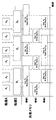
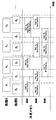
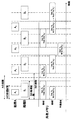
- FIG. 3 it is a diagram illustrating a memory management table Addition method at time T 4 immediately before. It is a flow diagram which shows the middleware operation in the 3rd Example of this invention. It is a flow diagram which shows the processing behavior at the time of the execution time constraint violation in the 4th Example of this invention. It is a figure which shows the method for continuing the process when the execution time constraint is violated in the 4th Example of this invention. It is a flow diagram which shows the middleware operation at the time of the execution time constraint violation in the 4th Example of this invention.
- FIG. 1 shows a configuration of a multi-core processor 1 mounted on an electronic control device for vehicle control and peripheral devices, which is the object of the present invention.
- the multi-core processor 1 is a multi-core processor having a plurality of CPU cores 2.
- a multi-stage cache configuration having a level 1 cache (L1 cache) 21 owned by each CPU core 2 and a level 2 cache (L2 cache) 22 shared by a plurality of cores is mainly used.
- L1 cache level 1 cache
- L2 cache level 2 cache
- the processing efficiency here is a performance index measured by the time required to complete the application processing. Therefore, not only the execution order of each application specified in advance, but also the internal state change of the processor (L2 cache 22 status, internal bus 3 load status) that dynamically changes according to the operation of each application. , Application processing status and order, memory access timing changes.
- the operating speed and quantity of the CPU core 2 When porting an application designed and verified on one multi-core processor 1 to another multi-core processor, the operating speed and quantity of the CPU core 2, the operating speed and the bus width of the bus 3, and the cache configuration (L1). Since changes in the components of the multi-core processor 1 such as cache 21, L2 cache 22, cache hierarchical structure such as lower L3 cache) and its size occur, application processing efficiency, execution order, and memory access timing may change. Change.
- the value required for the operation is read from the shared memory area accessible from all processes to the local memory area accessible only by itself (Fig.). It is configured to write the operation result to the shared memory at the end of the processing section (the part described as Copy-in in the figure) (Copy-out in the figure), and the operation is executed at any timing between this reading and writing.
- a time-synchronized timing design realization method using two buffers as shown in FIG. 3 is known.
- the processing section and period in the figure are from the start of processing (reading data from the shared memory area to the local memory area) to the completion of processing (writing data in the opposite direction when the calculation is completed) in the time-synchronized timing design method, respectively. It indicates the width of time and the unit for repeating such a processing interval.
- the process A is performed on the shared memory. It is composed of two memory areas, a memory area for write access and a memory area for read access by process B.
- a i and B i are symbols representing the processes of the i-cycles of processes A and B, respectively.
- the process may be preempted and restarted by a process (not shown) other than A and B.
- processing A i and B i point to the buffer area on the opposite side of the buffer area used immediately before, respectively , so that processing A i and B i are B i. It is possible to perform its own calculation using Res (B i-1 ) which is the result of -1 and write Res (A i-1 ) which is the calculation result of processing A i to the same area. Similarly, B also reads the processing result Res (A i-1 ) in the previous cycle of processing A and writes its own calculation result Res (B i ), so that the calculation processing proceeds. It should be noted that the processes A 1 and B 1 executed for the first time in this figure shall start the calculation without inputting data.
- the operation result written by the processing A in the i-th cycle is processed by B in the next i + 1th cycle and processing B in the i-th cycle. Since A refers to the calculation result written in the above in the next i + 1th cycle and continues the calculation, it is possible to continue the calculation without copying the data.
- this memory area is held only between two processes A and B having a data-dependent and order-dependent relationship and always has different buffer areas from each other, the respective memory areas are held during the processing sections of the processes A and B. It can be regarded as a local memory area that can be accessed only by processing.
- the cycles of process A and process B are not always the same.
- the input of this processing is linked to, for example, a laser range sensor that operates every 50ms and a vehicle speed sensor that operates every few ms. Processing is performed and the mapping result is updated.
- FIG. 4 shows an example of this operation when the cycles of process A and process B are different.
- the processing section and the period match will be described by omitting the swap timing description, but even if the two do not match, the arithmetic processing is realized by the same method.
- the timing of memory access and the number of required buffer areas differ depending on the cycle of processes A and B.
- the figure shows an example in which the period of A shown by the broken line (equal to the processing interval in this example) and the period of B shown by the alternate long and short dash line are different.
- An example of proceeding with processing using the latest processing result is shown. That is, the processes A and B each detect the process of the other party that has ended before the start of its own cycle, and read the memory area.
- This example shows an example in which the cycle of process A is longer than that of process B.
- the result Res (A i ) of a certain process A i is two or more. Multiple processing of Res (B j ), Res (B k ), ... There is a case where it is read in the calculation process.
- the result Res (A i ) of a certain process A i can be used for the calculation of up to two processes B. Become.
- the result Res (A i) is a memory area written in a certain process A i, since the process B j is destroyed in the process of calculating the operation result Res (B j), the process B k Since it is necessary to separately generate a memory area for calculating the calculation result Res (B j ), in this embodiment, it is necessary to newly copy the calculation result to another memory area after the calculation of the process A i is completed.
- the number of places to copy the calculation result is determined by the cycle of process A and process B.
- the result Res (A 2 ) of the process A 2 in the figure can be used for the process B 4 and the process B 5.
- the result Res (A 2 ) of the process A 2 in the figure can be used for the process B 4 and the process B 5.
- Res (A 2) the copy processing from the second half of the process A 2 that write to region 2 is started Cp (Res (A 2)) is an example to start operation, for example, a memory area 2 At the same time as processing A 2 secures, the copy destination memory area 4 may also be secured.
- the data copy overhead between process A and process B becomes similar to the case where data is exchanged using two memory areas between processes A and B having the same cycle as described above. It will be reduced. This is because the data copy process Cp (Res (A i )) is also performed during the process A i , so for example, when the subsequent process B 5 of the process A 2 starts, the data is already in the memory area. Because.
- a method of defining dedicated middleware can be considered.
- middleware application developers can concentrate on the behavior of applications without being aware of detailed memory management, and can also free applications from changing factors such as OS and hardware in industrial controls. It is possible and most consistent with the improvement of portability between different hardware (processors), which was the purpose of time-synchronized timing design.
- the above middleware manages the data on the shared memory that is updated for each processing section in each process, notifies the appropriate memory area at the start of each process, and has a memory area used for data transfer between each process. Two functions are required to maintain data transfer by creating a new memory area on the shared memory when there is a shortage. Each will be described below.
- FIG. 5 shows an example of a data management method on the shared memory.
- the necessary items in this method are to prevent other processes from accessing the memory area being calculated by one process, and to provide a memory area in which appropriate input information is written when each process is started. There are two points: handing over.
- the appropriate input information here is the latest calculation result of the other party processing that has been completed by the start time of the processing.
- the former is managed, for example, as the occupancy status of the memory area for data management on the memory, and the latter is managed as the position of the latest calculation result stored in the memory area.
- the latest calculation result is defined in both directions.
- the middleware searches for the item of process A from process B in the column of the latest process results in the management table of FIG. 7.
- the latest processing result calculation result of processing B 1
- the area is the area to be used by the processing A 2. Therefore, a check (dotted line circle in FIG. 7) is checked in the memory area 2 portion of the occupation status column by process A in the management table, and the address of the memory area is passed to process A to start process A 2.
- the check of the memory area 3 is removed from the occupancy status table by the process B, and instead, the check is put in the place of the area 3 of the latest value table from the process B to the process A.
- the memory management table is updated as shown in FIG. By updating the management table in this way, if another process A is started immediately after time T 2 , the memory area 3 can be used to perform an operation using the latest process result of process B. It will be possible.
- the time T 0 shown in FIG. 10 is the timing at which the writing of the calculation result is started in the process A.
- process A is defined as a long cycle with respect to process B, and it is necessary to provide a plurality of memory areas for data transfer from process A to process B. Therefore, the process A needs to secure a plurality of memory areas, but since the memory area secured at the same timing is only the area 1, it is necessary to secure a new write destination through the middleware.
- the middleware refers to the management table of FIG. 11, but the reserved memory area 1 and the memory area 3 are occupied by the processing A 1 and the processing B 2 , respectively, and the memory area 2 is the latest of the processing B.
- the process A 1 is the memory area does not exist that can be newly allocated. Therefore, a part of the shared memory ( corresponding to the write size of process A 1 ) is newly secured as a memory area for data transfer between process A and process B, and the occupied state on the management table is updated to A, and the memory area 4 is used. To create. By passing this memory area 4 to the process A, the latest value of the process A is written in both memory areas at the end of the process A 1.
- the above-mentioned memory management method using middleware is provided, and as in the case of data transfer using two memory areas between processes A and B having the same cycle as described above, between processes A and B. Data copy overhead is reduced in.
- an execution time constraint for each process or a series of a plurality of processes from the viewpoint of driving an actuator that operates along a fixed control cycle. If this is violated, the actuator control command value may not be output, or a command value inappropriate for the sensor input value may be output. Therefore, incomplete processing corresponding to the actuator is required.
- a control continuation method using another system using a redundant system configuration, a degenerate control method, and the like can be mentioned.
- the middleware since the scheduled end time of the application process is specified at the time of design, the above-mentioned incomplete process is executed for the case where the process is not completed by this timing.
- the middleware determines the necessity of executing incomplete processing, for example, by setting a flag when the middleware starts the processing and canceling this flag when the processing is completed, the middleware checks at the processing end time.
- the middleware checks at the processing end time.
- the middleware Since the middleware operates in a form that matches the start time of each process as described above, it is started by, for example, a timer interrupt at the process start time. In other words, a timer interrupt is inserted at the start time of each of the plurality of processes. After that, the latest processing result storage destination is searched from the management table (S100), and the occupancy status location of the management table is updated to secure the area (S101).
- the application process is started (S102).
- S102 when it is necessary to write data to a plurality of memory areas due to the length of the application processing cycle and such a write destination area is not secured, a new memory area is secured (S103).
- S103 and S104 are skipped and S105 is executed. Then, at the end time of application processing, a timer interrupt is inserted as at the start time. In other words, a timer interrupt is inserted at the end time of each of the plurality of processes.
- the latest value status of the memory management table is updated (S107), and the memory occupancy status is released (S108). This completes the middleware processing for one application processing.
- the electronic control device of the present embodiment includes a processor (multi-core processor 1) including a plurality of cores (CPU cores 2) that execute a plurality of processes operating at different cycles, and the plurality of processes that execute the plurality of processes.
- a memory shared memory including a plurality of memory areas that can be accessed for each core (CPU core 2), and the memory that can be accessed by a preceding process for writing data and a subsequent process for reading data. Change the area according to the progress of processing.
- the processor (multi-core processor 1) searches for a writable memory area in which the latest processing result has not been written and is not being read, and secures a new memory area when there is no writable memory area. , By setting a new memory area as the write destination of the processing result, the processing result is passed from the preceding processing to the succeeding processing.
- the electronic control device includes a table that stores the occupancy status for each memory area and the presence / absence of the latest value of the processing result.
- the processor determines that the writable memory area does not exist for all the memory areas of this table if the occupancy status indicates that it is occupied or the presence or absence of the latest value indicates that the latest value is stored.
- Example 2 Hereinafter, the second embodiment according to the present invention will be described with reference to the drawings.
- the assumed CPU configuration (FIG. 1) and the time-synchronized timing design method to be applied (FIG. 2) conform to the first embodiment, but in this embodiment, a one-way data dependency relationship between a plurality of processes A and B.
- An application example of the present invention in a certain case, that is, a case in which the process B is executed using the execution result of the process A but the reverse does not exist, will be described mainly focusing on the difference from the first embodiment.
- FIG. 13 shows a processing configuration as an example of the present invention.
- the memory area is composed of three different memory areas (areas 1 to 3).
- the processing B since the processing B is configured to read the calculation result of the processing A, in the shared memory area description in the figure, the processing A only writes its own calculation result. , Process B describes only the reading of the operation result of process A, respectively.
- the same memory configuration can be adopted even when the cycle of process A is further smaller than the cycle of process B. .. In this way, in the case where the cycle of process B is more than twice the cycle of process A, the process result is overwritten in the memory area that is not the latest value in the memory management table shown in Example 1. This eliminates the need for further addition of the shared memory area.
- the process B 2 is read out the operation result of the processing A 2 Res (A 2) Just do it. Therefore, as shown in the figure, the operation result Res (A 3 ) of the process A 3 is allowed to overwrite the operation result Res (A 1 ) of the process A 1 in the memory area 2.
- the above configuration that is, only three shared memory areas as in this embodiment.
- FIG. 16 shows a processing configuration as an example of the present invention.
- the process A is configured to perform only writing and the process B is configured to perform only reading, but a case where the processing section of A and the period of A do not match will be described as an example.
- the processing interval and the period do not necessarily have to match, so that such a configuration can be adopted.
- the processing A 4 is completed before the calculation result of the processing A 3 Res (A 3) is read out, the processing B 4 arithmetic processing A 4
- the result Res (A 4 ) can be used to start the operation.
- the utilization rate of the shared memory area is lowered, and the memory efficiency is deteriorated.
- the minimum required two memory areas are configured on the shared memory (similar to the case of the same cycle), and the third memory area is dynamically allocated from the shared memory as needed, and it is determined that it is unnecessary. If this is the case, the spare area can be accommodated between the processing configurations of the entire control device, and the memory efficiency can be further improved.
- the memory area is composed of two different memory areas, and the processor (multi-core processor 1) secures a new memory area when there is no writable memory area. After that, for example, under the condition that the memory area has three or more memory addresses, the processor (multi-core processor 1) determines that one memory address is not the write destination of the latest processing result and is not being read. In, the one memory address is released.
- the above configuration is shown by the method of realizing the above configuration by memory management by middleware.
- the memory area management process is realized by the processor (multi-core processor 1) executing dedicated middleware.
- the middleware processing described in the present embodiment may be performed inside the OS or each processing.
- the memory state immediately after time T 3 is as shown in FIG. 19, the memory area 2 is occupying B and the latest processing result is written, and the spare area is blank. In this way, with the completion of processing A 4 , the spare area can be released in the case where the spare area is not occupied and the latest value is not written. When the cycle of process A is longer than that of process B, the latest value is not written and the area can be released when process A does not need to occupy the spare area.
- middleware processing it is possible to apply to all cases by adopting a configuration that determines whether memory can be released at the start of processing (when the cycle of processing A is shorter than processing B, Overhead continues until the next process A starts).
- FIG. 20 shows such a middleware behavior flow.
- the basic configuration is the same as that of the first embodiment, but since the process A and the process B perform either the write process or the read process, the flow is slightly different depending on this discrimination mechanism. Therefore, when the process is started, a conditional branch of read process or write process is entered. After that, the middleware processing of the first embodiment is followed. What is added in this example is the case where a writable area exists on the write processing side. At this time, if the number of managed memory areas is 3 or more and the spare area does not hold the latest value and is not being read, it can be released and the memory area is deleted from the management table (S109).
- this embodiment can be realized even with a configuration of two memory areas that are always allocated on the management table and one memory area that is dynamically allocated / released as needed.
- the release condition of the management memory area is that the management address is three or more, and the latest value is not held and the reading is not in progress, so that the address can be deleted from the management table.
- the S109 process changes to search for and delete the memory area.
- the industrial electronic control device is configured to calculate the control command value based on the input of sensor information and control the actuator.
- the actuator in order to correctly control the actuator that operates periodically, there is generally an execution time constraint between the sensor input and the control command value output.
- the software behavior among a plurality of cores described above can easily change according to the processor state at the time of execution, so that the execution time fluctuates, for example.
- Such fluctuations in execution time are dealt with by margin design at the time of design, but the completion of processing is not always guaranteed due to strict execution time restrictions and competition of various resources. Therefore, it is necessary for the middleware to confirm the completion of processing and to take measures when it is not completed.
- FIG. 21 shows an example in which process A 2, which is the second execution of process A in the figure, could not complete the process within the specified process section due to the influence of the execution time fluctuation.
- the middleware stops process A 2 and does not update the memory management table, so that process B 4 and process B 5 that should have used the operation result Res (A 2 ) of process A 2 Control so that the value whose calculation is not completed is not used.
- These processes continue to be controlled by using the operation result Res (A 1 ) of the process A 1.
- the processor that executes the middleware performs incomplete processing that forcibly stops the processing when it detects that the processing is incomplete at the end times of each of the plurality of processes.
- Another method is to extend the execution time of process A by using the design-time margin of the subsequent process that processes using the result of the preceding process, such as process B for process A, in such a case. , It is a method to pass the latest processing result to the subsequent processing B.
- processor that executes the middleware detects that the processing has not been completed at the end time of each of the plurality of processes, the processor that executes the middleware starts the subsequent processing that performs the calculation using the calculation result of the processing. By delaying the time by the grace time specified at the time of design, the calculation is continued using the latest calculation processing result in the subsequent processing.
- both the process A 2 subsequent processing process which is the B 4, and the influence of delay in processing A 2 by the number of cores leads to reduction own processing time processing A 3 are both margin time, i.e. the processing block There is a difference between the execution time of each process and the execution time of each process. This time is usually used to absorb the fluctuation of the execution time on the multi-core as described above, but since the worst execution time at the time of design does not always occur, the same margin time should be used. Is possible.
- the margin time is designed to be the worst execution time + 20%, and 10% of the margin time can be applied to such a delay in advance processing.
- a time is called a delayed absorption time (FIG. 22).
- the affected process process B 4 and, for example, 2 cores
- the middleware acquires the latest delayed absorption time end time (time T 4 in the figure) from task information, etc., and continues processing A 2 until the same time. If process A 2 is completed at the same time, the same termination process as the memory management described in Example 3 is performed, and if process A 2 is not completed at the same time, the above-mentioned first method is used. Take the same forced termination process.
- FIG. 23 shows a flow chart relating to the middleware behavior in this embodiment.
- the present invention can comply with the real-time constraints required for industrial control devices.
- the second countermeasure shown above even if the real-time constraint is violated, processing is continued or processing is continued using the latest processing result when it is possible to deal with it using the margin time in processing execution. By making it possible, it is possible to continue the control calculation by the industrial control device and improve its accuracy.
- the present invention is not limited to the above-described embodiment, but includes various modifications.
- the above-mentioned examples have been described in detail in order to explain the present invention in an easy-to-understand manner, and are not necessarily limited to those having all the described configurations.
- it is possible to replace a part of the configuration of one embodiment with the configuration of another embodiment and it is also possible to add the configuration of another embodiment to the configuration of one embodiment.
- each of the above configurations, functions, etc. may be realized by hardware, for example, by designing a part or all of them with an integrated circuit. Further, each of the above configurations, functions, and the like may be realized by software by the processor interpreting and executing a program that realizes each function. Information such as programs, tables, and files that realize each function can be placed in a memory, a recording device such as a hard disk or SSD (Solid State Drive), or a recording medium such as an IC card, SD card, or DVD.
- a recording device such as a hard disk or SSD (Solid State Drive)
- a recording medium such as an IC card, SD card, or DVD.
- the embodiment of the present invention may have the following aspects.
- An electronic control unit having a processor including a plurality of cores, wherein the processor executes a plurality of processes operating in different cycles, and the plurality of processes accessible to each of the plurality of cores performing the plurality of processes.
- the latest result of the processing in the electronic control device which has a memory area and changes the memory area which can be accessed by the preceding processing for writing data and the succeeding processing for reading data according to the progress of the processing. Is not written and is not being read, the writable memory area is searched, and if the writable memory area does not exist, a new memory area is secured and the new memory area is used for the processing.
- An electronic control device characterized in that the result of the processing is passed from the preceding processing to the succeeding processing by setting the writing destination of the result.
- Multi-core processor 2 CPU core 21: L1 cache 22: L2 cache 3: Internal bus 4: External memory 5: Sensor
Landscapes
- Engineering & Computer Science (AREA)
- Theoretical Computer Science (AREA)
- Software Systems (AREA)
- Physics & Mathematics (AREA)
- General Engineering & Computer Science (AREA)
- General Physics & Mathematics (AREA)
- Computer Hardware Design (AREA)
- Multi Processors (AREA)
- Memory System (AREA)
Abstract
時刻同期型設計におけるアプリケーション間におけるデータ受渡の効率を高めることが可能な電子制御装置が提供される。電子制御装置は、異なる周期で動作する複数の処理を実行する複数のコアを含むプロセッサと、複数の処理を実行する前記複数のコアごとにそれぞれアクセス可能な複数のメモリ領域を含むメモリと、を備え、データ書込みを行う先行処理とデータ読出しを行う後続処理とがそれぞれアクセス可能な前記メモリ領域を処理の進捗に応じて変更する。プロセッサは、最新の処理の結果が書き込まれておらず、かつ読出し中でない書込み可能なメモリ領域を探索し、書込み可能なメモリ領域が存在しない場合、新たなメモリ領域を確保し、新たなメモリ領域を処理の結果の書き込み先とすることで、先行処理から後続処理へ処理の結果を受け渡す。
Description
本発明は、電子制御装置に関する。
近年、産業用電子制御装置(ECU: Electronic Control Unit)を支える組込みシステムの開発においては、制御性能の向上、厳格化する規制への対応、装置の自律化に伴う制御演算処理増大等による、搭載アプリケーションの複雑化・高負荷化が進んでいる。これに対応する形で、ECUに搭載されるプロセッサにおいてもマルチコア/メニーコア化によるハードウェアの高性能化が進んでいる。
一方で、これら高性能化したハードウェア上に搭載されるソフトウェア開発においては、前述のマルチコア化、メニーコア化に対応したソフトウェア開発が求められ、設計、開発、検証の複雑さが増大する。この原因としてはマルチコアプロセッサの開発において複数のコアが同時に共有資源であるバスやメモリ、キャッシュにアクセスすることから、シングルコアプロセッサ開発と異なりソフトウェア挙動が実行時のプロセッサ状態に応じて容易に変化し得ることが挙げられる。
また、このような課題を解決して製品化を完了した後も、プロセッサ毎に共有資源に関するパラメタ(バス幅、メモリサイズ、キャッシュサイズ)が異なることから、あるプロセッサ上での開発結果を別プロセッサへと移植することも単純ではなく、同様に設計、開発、検証の工数が増大してしまう。
このようなプロセッサ構成の複雑化とそれに伴う工数増に対する方策として、車載ソフトウェアアーキテクチャに関する標準規格であるAUTOSARにおいてタイミング設計に関して時刻同期型のタイミング設計方式であるLET(Logical Execution Time)パラダイムが定義されている。同方式は上流工程でメモリアクセスタイミングの決定を中心とするタイミング設計を行い、このタイミングを各処理が実行時に守ることを特徴としており、これにより各処理の開始/終了時刻におけるメモリ状態が一定となることから、プロセッサ状態の組合せによる開発、検証パターン増を防ぐことができ、工数低減に寄与することができる。
また、異なるプロセッサ間での移植においても、あるプロセッサに対するタイミング設計結果は、別のプロセッサにおいても性能上タイミングを満たすことができる限りにおいて、そのまま移植することが可能となる。
一方で、同パラダイムの構成を実現するためには、データコピーが多発する。これは、同パラダイムが複数タスク間でのデータ共有を行う共有メモリ領域と、各処理が実行時に占有するローカルメモリ領域との間において、処理の開始/終了時にデータコピーを行うような構成を取ることによる。このため大規模なデータを処理間でやり取りするような処理においては、従来設計方式に対しデータコピーのための時間オーバヘッドが大となることから、アプリケーション処理の効率低下が発生する要因となる。
先行特許文献1では、このようなマルチコアプロセッサにおけるコア間通信オーバヘッドを低減する方式として、バッファを用いた解決法が示されている。
一方で、同方式においては、通信機器を前提とした固定的なパケットサイズを単位とする個数管理に対する実装方式が定義されているが、産業用制御装置においては処理間でのデータ通信毎に、その通信量が異なることが特徴である。このように異なるメモリサイズでの処理に対しても、高速なデータ受渡方式が必要である。また、産業用電子制御装置においては、一定の制御周期に沿って動作するアクチュエータを駆動する観点から、各処理、もしくは一連の複数処理が複数の異なる周期で動作することが想定されため、同データ受渡し方式においてはデータ入出力関係のある複数の処理が異なる周期で動作するケースへの対応が求められる。
本発明の目的は、時刻同期型設計におけるアプリケーション間におけるデータ受渡の効率を高めることが可能な電子制御装置を提供することにある。
上記目的を達成するために、本発明は、異なる周期で動作する複数の処理を実行する複数のコアを含むプロセッサと、前記複数の処理を実行する前記複数のコアごとにそれぞれアクセス可能な複数のメモリ領域を含むメモリと、を備え、データ書込みを行う先行処理とデータ読出しを行う後続処理とがそれぞれアクセス可能な前記メモリ領域を前記処理の進捗に応じて変更する電子制御装置であって、前記プロセッサは、最新の前記処理の結果が書き込まれておらず、かつ読出し中でない書込み可能な前記メモリ領域を探索し、書込み可能な前記メモリ領域が存在しない場合、新たな前記メモリ領域を確保し、新たな前記メモリ領域を前記処理の結果の書き込み先とすることで、前記先行処理から前記後続処理へ前記処理の結果を受け渡す。
本発明によれば、時刻同期型設計におけるアプリケーション間におけるデータ受渡の効率を高めることができる。上記した以外の課題、構成及び効果は、以下の実施形態の説明により明らかにされる。
(実施例1)
以下、本発明に係る第1の実施例について図面を用いて説明する。
以下、本発明に係る第1の実施例について図面を用いて説明する。
図1に、本発明が対象とする、車両制御向け電子制御装置に搭載されるマルチコアプロセッサ1、および周辺機器の構成を示す。このマルチコアプロセッサ1は複数のCPUコア2を有するマルチコアプロセッサである。このようなマルチコアプロセッサ1においては、各CPUコア2がそれぞれ有するレベル1キャッシュ(L1キャッシュ)21と、複数コアにより共有されるレベル2キャッシュ(L2キャッシュ)22を有する多段キャッシュ構成が主に用いられ、各コア上での命令実行効率を高める工夫が為されている。各CPUコアは内部バス3を通じてプロセッサ外部にある外部メモリ4や、電子制御装置内外の各種センサ5に接続される。なお、簡単のためマルチコアプロセッサ1内部の詳細構成(各種機構や、詳細なバス構造)は省略する。
このようなマルチコアプロセッサ1上において、複数のコア上で同時にアプリケーション処理を行う場合、複数のCPUコア2が共有する外部メモリ4上のデータに対するアクセス競合、内部バス3にかかる負荷や複数プロセスからのメモリ利用に伴うL2キャッシュ22のキャッシュヒット率変化により、各アプリケーションの処理効率が変化する。
ここでの処理効率は、アプリケーション処理完了までに要する時間により測定される性能指標である。このため、事前に規定された各アプリケーションの実行順序だけでなく、各アプリケーションの動作に応じて動的に変化するプロセッサの内部状態変化(L2キャッシュ22状況、内部バス3負荷状況)に応じる形で、アプリケーション処理の状況や順序、メモリアクセスタイミングが変化する。
さらに、割込み処理など、動作タイミングを設計時に確定させることが難しいアプリケーションも存在することから、マルチコアプロセッサ上におけるアプリケーション設計、開発、デバッグ、および検証は、取り得るプロセッサ状態を鑑みてそれぞれ為される必要があり、これら各作業の複雑化と工数増大が懸念される。
また、あるマルチコアプロセッサ1上にて設計・検証されたアプリケーションを、別のマルチコアプロセッサに移植する場合は、CPUコア2の動作速度や数量、バス3の動作速度およびバス幅、キャッシュの構成(L1キャッシュ21、L2キャッシュ22、場合によっては更に下位のL3キャッシュなどのキャッシュ階層構造)やそのサイズといったマルチコアプロセッサ1の構成要素変化が発生するため、アプリケーション処理効率やそれに伴う実行順序、メモリアクセスタイミングが変化する。
そのため、あるプロセッサ1を対象とした設計結果を他のプロセッサ上に移植した際には、必ずしも同等の挙動を示すとは限らず、同様に設計、開発、デバッグ、検証の工程が必要となってしまう。
このようなマルチコアプロセッサ1の利用、および他マルチコアプロセッサへの移植を意識した設計方式として、各アプリケーションの処理開始および完了タイミングを規定する時刻同期型の設計方式が知られている。同設計方式について、図2を用いて説明する。
同設計方式においては、各アプリケーション毎に定められた周期の最初に、全ての処理からアクセス可能な共有メモリ領域から、自身のみがアクセス可能なローカルメモリ領域に演算に必要となる値を読み込み(図中Copy-inと記載した部分)、処理区間の最後に共有メモリに演算結果を書き出す(図中Copy-out)ように構成され、演算はこの読み込みから書き出しまでの間の任意のタイミングで実行される。
同設計方式では、このようにローカルメモリ空間上でアプリケーション処理を実行することにより他アプリケーション処理とのメモリ競合を避けると同時に、処理区間の最後における共有メモリへの書き出し順序を設計時に定義することで、CPUコアやバスの動作速度、キャッシュサイズ、コア数変更に伴うアプリケーション実行コア変化などの挙動変化要因に対しても、設計時に定められた処理時間内に処理が完了する限りにおいて、プロセッサ状態に依らずに共有メモリ状態を一致させられることが期待される。
これにより、プロセッサ状態に起因するアプリケーション処理の挙動変化を抑制すると同時に、また異なるプロセッサ間における高い移植性を得ることができる方式となる。
このような方式を実現する方法の1つとして、前述のようなデータコピーを用いた共有メモリ、ローカルメモリ構成が知られているが、同データコピー方式では特にアプリケーション処理が利用するメモリサイズが大となる場合において、データコピーに要する時間オーバヘッドが大きくなる課題がある。
そこで、図3に示すような2つのバッファを用いた時刻同期型タイミング設計実現手法が知られている。なお、同図における処理区間と周期は、それぞれ時刻同期型タイミング設計方式における処理開始(共有メモリ領域からローカルメモリ領域へデータを読出し)から処理完了(演算完了時にデータを逆方向に書込み)までの時間の幅、およびこのような処理区間を繰り返す際の単位を示すものである。
また図面記載の都合からSwap処理の後に処理Aおよび処理Bがアクセスするメモリ領域が指し示されるまでに時間を要す記載となっているが、実際にはSwap処理の終了時点において各処理がアクセスするメモリ領域は決定されている。
同手法においては、データ依存関係を有する2つの処理A、B(A、Bが互いに前周期の相手の演算結果を用いて、次周期に演算を行う)に対し、共有メモリ上に処理Aが書込みアクセスを行うメモリ領域と処理Bが読出しアクセスを行うメモリ領域との2つのメモリ領域から構成される。ここで、Ai、Biはそれぞれ処理A、 Bのi周期目の処理の処理を表す記号とする。また、上記のように記載される各処理中においては、A、 B以外の図示しない処理によりプリエンプトされ、再開していてもよい。
このような構成をとると、i番目の処理区間の開始時に、処理AiおよびBiはそれぞれ自身が直前に用いたバッファ領域と反対側のバッファ領域を指すことで、処理AiはBi-1の結果であるRes(Bi-1)を用いて自身の計算を行い、処理Aiの演算結果であるRes(Ai-1)を同領域に書込む動作を行うことができる。Bも同様に、処理Aの前周期における処理結果Res(Ai-1)を読み込み、自身の演算結果Res(Bi)を書込むことで、演算処理が進んでいく。なお、本図おいて初回に実行される処理A1およびB1は、データの入力なしで演算を開始するものとする。
ここで、本動作における各メモリ領域の状態に着目すると、i番目の周期に処理Aにより書込まれた演算結果を、次のi+1番目の周期にBが、i番目の周期に処理Bにより書込まれた演算結果を、次のi+1番目の周期にAが、それぞれ参照して演算を継続するため、データをコピーすることなく演算を継続することが可能となる。
また、このメモリ領域は、データ依存かつ順序依存関係を有する2つの処理A、Bの間でのみ保有され、かつ常に互いに異なるバッファ領域を有することから、処理A、Bの処理区間中はそれぞれの処理のみがアクセス可能なローカルメモリ領域と見做すことができる。
以上から本構成を用いることで、時刻同期型タイミング設計方式における演算構造を実現しつつ、データコピーに要する時間オーバヘッドを削減することが可能となる。
一方で、処理Aと処理Bの周期は必ずしも同一であるとは限らない。例えば自動運転処理を想定すると、自車周辺状況をマッピングする処理が存在するが、同処理の入力は例えば50ms毎に動作するレーザレンジセンサや数ms毎に動作する自車速度センサに連動して処理が行われ、マッピング結果が更新される。
また、パワートレイン分野に目を向けると、例えばエンジン処理のようなケースにおいてはエンジン回転数に同期した処理が発生するため、動作中に制御周期が変化するケースもある。このように異なる周期で動作する処理間でデータ授受が発生する場合は、前述のようにメモリ領域を固定し、同時に更新するような形での方式実現は困難となる。
特に制御周期変化に対応するためには、制御装置の状態に合わせた動的なメモリ領域の管理が必要となる。図4に、処理Aと処理Bの周期が異なる場合の、本動作の例を示す。なお、図面記載の簡単のため、本例では処理区間と周期とが一致する場合について、スワップタイミング記載を省略して説明するが、両者が一致しない場合においても同様の方式により演算処理が実現される。また処理A、Bの周期によっても、メモリアクセスのタイミングや必要となるバッファ領域数が異なる点に注意が必要である。
同図においては、破線で示したAの周期(本例では処理区間に等しい)と、一点鎖線で示したBの周期とが異なっている例を示しており、A、 Bは互いに極力相手の最新処理結果を用いて処理を進める例を示す。すなわち、処理A、 Bが互いに、自身の周期が開始される以前に終了している相手の処理を検出し、当該メモリ領域を読み出す構成を取る。
本例では、処理Aの周期が処理Bよりも長い例を示しているが、これにより、処理AおよびBの開始タイミングによっては、ある処理Aiの結果Res(Ai)が、2つ以上の複数の処理Res(Bj)、Res(Bk)、…の演算過程において読み出されるケースが発生する。同図においては、処理Aの周期は処理Bの周期の2倍以下となっていることから、ある処理Aiの結果Res(Ai)は、最大2つの処理Bの演算に用いられることとなる。
上記の例では、ある処理Aiの結果Res(Ai)が書き込まれたメモリ領域は、処理Bjが演算結果Res(Bj)を演算する過程で破壊されてしまうことから、処理Bkが演算結果Res(Bj)を演算するメモリ領域を別途生成する必要があるため、本実施例では処理Aiの演算終了後に、新たに別のメモリ領域に演算結果をコピーする必要がある。演算結果をコピーする箇所数は、処理Aと処理Bの周期により定まる。
この領域数は、
(処理Aの周期)/(処理Bの周期)
の小数点以下を切り上げた数を最小値とする値が取られることとなる。
(処理Aの周期)/(処理Bの周期)
の小数点以下を切り上げた数を最小値とする値が取られることとなる。
図4に示したコピー処理Cp(Res(Ai))を行うことで、例えば図中処理A2の結果Res(A2)は、処理B4および処理B5に用いることが可能となる。なお、本図では処理A2の演算結果を自身の保有するメモリ領域2に書込む際、同時に別メモリ領域4へ同時に書込む例を想定した。このため、Res(A2)の領域2への書込みが開始される処理A2の後半部分からコピー処理Cp(Res(A2))が動作開始する例を示しているが、例えばメモリ領域2を処理A2が確保すると同時に、コピー先のメモリ領域4も確保する構成を取っても構わない。
このようなメモリ管理構成をとることで、先述の同じ周期の処理A、B間において2つのメモリ領域を用いたデータ授受を行った場合と同様、処理Aと処理B間でのデータコピーオーバヘッドは削減される。これは、またデータコピー処理Cp(Res(Ai))も処理Ai実行中に行われることから、例えば処理A2の後続処理B5の開始時には、既にデータがメモリ領域上に備わっているためである。
以上のメモリ管理構成を実現する手段として、専用のミドルウェアを定義する方法が考えられる。ミドルウェアを定義することで、アプリケーション開発者は細かなメモリ管理を意識せずアプリケーションの挙動に集中することができ、また産業用制御装置におけるOSやハードウェアといった変化要素からもアプリケーションを解放することができ、時刻同期型タイミング設計の目的であった異なるハードウェア(プロセッサ)間での移植性向上と最も整合する。
同方式を、ミドルウェアを用いて実現する場合の実装方法の例としては、ミドルウェアが当該メモリ領域を管理し、アプリケーション側にはメモリ領域を示すポインタとして渡す方法などが想定される。本実施例においては、この方式に基づき説明する。
上記のミドルウェアには、各処理における処理区間毎に更新される共有メモリ上のデータを管理し各処理の起動時に適切なメモリ領域を通知すること、および各処理間でデータ授受に使うメモリ領域が不足した際に共有メモリ上に新たなメモリ領域を作成することでデータ授受を維持すること、の2つの機能が求められる。それぞれについて、以下説明する。
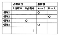
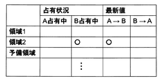
まず、共有メモリ上のデータ管理方法の例を、図5に示す。
本方式における必要事項は、ある処理が演算中のメモリ領域に、他の処理がアクセスすることを防ぐこと、および各処理が開始される際に適切な入力情報が書込まれているメモリ領域を渡すこと、の2点である。ここでの適切な入力情報とは、当該処理の開始時刻までに完了している、最新の相手処理の演算結果である。
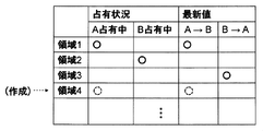
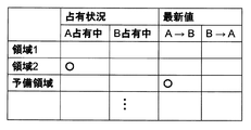
前者は例えばメモリ上のデータ管理にはメモリ領域の占有状況として、後者はメモリ領域に格納された最新演算結果の位置として、それぞれ管理される。本例では、複数の処理が相互にデータを授受する構成であるため、最新演算結果は双方向に定義される。
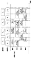
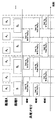
図6および図7を用いて、本実施例における処理A2開始時(時刻T1)におけるミドルウェア挙動を説明する。時刻T1においては、メモリ領域3が処理B2により占有されている。また、処理A1および処理B1が、当該時刻の開始時刻までに完了した最新の処理となるため、処理A1に関してはメモリ領域1および4が、処理B1に関してはメモリ領域2が、それぞれ最新処理結果であることが示される。本例では前述のように、処理Aの周期が処理Bより長いことから、処理Aは複数個所に演算結果を保存している。
時刻T1にて起動される処理A2に対し、ミドルウェアは図7の管理テーブルにおける最新処理結果の列のうち、処理Bから処理Aの項目を検索する。結果、領域2に最新処理結果(処理B1の演算結果)が記載されていることから、当該領域が処理A2の利用すべき領域と分かる。そこで、管理テーブルにおける処理Aによる占有状況欄のメモリ領域2部分にチェック(図7の点線の丸)を入れ、当該メモリ領域のアドレスを処理Aに渡すことで処理A2を起動する。
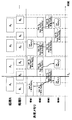
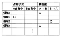
次に、時刻T2にて処理B2が終了した際の挙動を図8および図9を用いて説明する。図8に示すように、同時刻において処理A2は継続していること、および当該時刻での最新演算結果が処理B2の結果となることから、処理B2が占有していたメモリ領域3が最新の演算結果を保持している領域と分かる。
そこで、処理Bによる占有状況テーブルからメモリ領域3のチェックを外し、代わりに処理B→処理Aへの最新値テーブルの領域3の箇所にチェックを入れる。これにより、メモリ管理テーブルが図9のように更新される。このように管理テーブルが更新されることで、時刻T2直後に別の処理Aが起動された場合には、メモリ領域3を用いることで処理Bの最新処理結果を用いた演算を行うことが可能となる。
次に、各処理間でデータ授受に使うメモリ領域が不足した際に共有メモリ上に新たなメモリ領域を作成することでデータ授受を維持する方法について、図10および図11を用いて説明する。
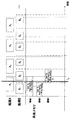
図10に示した時刻T0は、処理Aにおいて演算結果の書込みが開始されたタイミングである。前述のように、処理Aは処理Bに対して長い周期と定義されており、処理Aから処理Bへのデータ授受については複数のメモリ領域を備える必要がある。そこで、処理Aは複数のメモリ領域を確保する必要があるが、同タイミングにおいて確保されているメモリ領域は領域1のみであるため、ミドルウェアを通じて新たな書込み先を確保する必要がある。
そこで、ミドルウェアは図11の管理テーブルを参照するが、確保されているメモリ領域1およびメモリ領域3は処理A1、処理B2にそれぞれ占有されており、またメモリ領域2には処理Bの最新処理結果が格納されていることから、処理A1が新たに確保することができるメモリ領域が存在しない。そこで、新たに共有メモリの一部(処理A1の書込みサイズに相当)を処理A-処理B間のデータ授受用メモリ領域として確保および管理テーブル上の占有状態をAと更新し、メモリ領域4を作成する。このメモリ領域4を処理Aに渡すことで、処理A1の終了時には処理Aの最新値が両メモリ領域に書込まれた状態となる。
以上の構成によりミドルウェアを用いた上述のメモリ管理方式が提供され、先述の同じ周期の処理A、B間において2つのメモリ領域を用いたデータ授受を行った場合と同様、処理Aと処理B間でのデータコピーオーバヘッドは削減される。
また、産業用電子制御装置においては、一定の制御周期に沿って動作するアクチュエータを駆動する観点から、各処理、もしくは一連の複数処理に対する実行時間制約(リアルタイム制約)が存在する。これに違反した場合、アクチュエータ制御指令値が出力されない、もしくはセンサ入力値に対して適切でない指令値が出力される可能性があるため、アクチュエータに対応した未完了時処理が必要となる。例えば、冗長系構成を用いた別系統を利用した制御継続方式や、縮退制御方式などが挙げられる。
本構成においては、アプリケーション処理の終了予定時刻が設計時に規定されていることから、このタイミングまでに処理が完了しないケースに対して前述の未完了処理が実行される。未完了処理実施の要否をミドルウェアが判別するためには、例えばミドルウェアが処理を起動する際にフラグをセットし、処理の完了時にこのフラグを解除することで、処理終了時刻においてミドルウェアがチェックするような実装が考えられる。
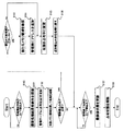
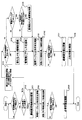
以上の構成を実現するミドルウェア挙動について、図12のフローチャートを用いて説明する。ミドルウェアは前述のように各処理の起動時刻に合わせる形で動作するため、例えば処理開始時刻のタイマ割込みにより起動される。換言すれば、複数の処理のそれぞれの開始時刻においてタイマ割込みが入る。その後、管理テーブルから最新処理結果格納先を探索し(S100)、当該領域を確保するため管理テーブルの占有状況箇所を更新する(S101)。
そして、当該メモリ領域を処理に渡して処理を起動することで、アプリケーション処理が開始される(S102)。ここで、アプリケーション処理の周期の長短により、複数のメモリ領域へデータを書込む必要があり、かつそのような書込み先領域が確保されていない場合には新たなメモリ領域を確保し(S103)、管理表にアドレスを追加(S104)、当該書込み先の状態を占有中に変更した上で(S105)、処理に渡す(S106)。
書込み先領域がミドルウェアにより既に確保され管理テーブルに記載されている場合は、S103およびS104をスキップし、S105が実施される。そして、アプリケーション処理終了時刻には開始時と同様にタイマ割込みが入る。換言すれば、複数の処理のそれぞれの終了時刻においてタイマ割込みが入る。アプリケーション処理終了時においては、メモリ管理テーブルの最新値状態を更新し(S107)、メモリ占有状態を解除する(S108)。以上により、1つのアプリケーション処理に対するミドルウェア処理が完結する。
換言すれば、本実施例の電子制御装置は、異なる周期で動作する複数の処理を実行する複数のコア(CPUコア2)を含むプロセッサ(マルチコアプロセッサ1)と、複数の処理を実行する前記複数のコア(CPUコア2)ごとにそれぞれアクセス可能な複数のメモリ領域を含むメモリ(共有メモリ)と、を備え、データ書込みを行う先行処理とデータ読出しを行う後続処理とがそれぞれアクセス可能な前記メモリ領域を処理の進捗に応じて変更する。プロセッサ(マルチコアプロセッサ1)は、最新の処理の結果が書き込まれておらず、かつ読出し中でない書込み可能なメモリ領域を探索し、書込み可能なメモリ領域が存在しない場合、新たなメモリ領域を確保し、新たなメモリ領域を処理の結果の書き込み先とすることで、先行処理から後続処理へ処理の結果を受け渡す。
図5に示すように、電子制御装置は、メモリ領域ごとの占有状況と処理の結果の最新値の有無を格納するテーブルを備える。プロセッサは、このテーブルのすべてのメモリ領域について、占有状況が専有を示し、または最新値の有無が最新値を格納していることを示す場合、書込み可能な前記メモリ領域が存在しないと判定する。
以上の構成により、マルチコアCPUにおける設計、開発、検証工数を低減する時刻同期型タイミング設計方式を低時間オーバヘッドに実現し、かつ異なるハードウェア(プロセッサ)間での移植性向上を実現する方式が提供される。
(実施例2)
以下、本発明に係る第2の実施例について図面を用いて説明する。想定するCPU構成(図1)や適用する時刻同期型タイミング設計方式(図2)は実施例1に準拠するが、本実施例では複数の処理Aおよび処理Bの間に一方向のデータ依存関係があるケース、すなわち処理Aの実行結果を利用して処理Bが実行されるが、逆は存在しないケースにおける本発明の適用事例を、主に実施例1との差分に着目して説明する。
以下、本発明に係る第2の実施例について図面を用いて説明する。想定するCPU構成(図1)や適用する時刻同期型タイミング設計方式(図2)は実施例1に準拠するが、本実施例では複数の処理Aおよび処理Bの間に一方向のデータ依存関係があるケース、すなわち処理Aの実行結果を利用して処理Bが実行されるが、逆は存在しないケースにおける本発明の適用事例を、主に実施例1との差分に着目して説明する。
本実施例においては、処理B実行に必要な処理Aの演算結果のみを共有メモリ上に展開することで、例えば処理Aへの入力データといった処理B実行に不要なデータを共有メモリ上に複数保持する必要がなく、処理間のメモリ利用効率の向上および、これに伴う制御装置内におけるメモリ利用効率向上、最終的には制御装置に搭載するメモリサイズ低減による低コスト化が期待される。
図13に、本発明が例題とする処理構成を示す。本実施例では、メモリ領域は3つの異なるメモリ領域(領域1~3)から構成される。前述のように、本実施例においては、処理Aの演算結果を処理Bが読込む構成となっていることから、図中の共有メモリ領域記載においては、処理Aは自身の演算結果の書込みのみ、処理Bは処理Aの演算結果の読込みのみ、をそれぞれ記載している。
処理Aが自身の演算に用いる読込データや、処理Bが自身の演算結果を書込む領域については、図中の共有メモリ領域に書込む構成をとることも、それ以外のデータ依存関係を有する処理との間で同様の共有メモリ構成をとることも、可能である。
このような共有メモリの利用方式においては、処理A、Bの2つの処理間でデータ共有する場合については、処理Aの書込み先が2箇所(処理Aの周期が処理Bの周期より短い場合)と、処理Bの読出し先が1ヶ所の合計3箇所以上あれば、実施例1に記載のデータ受渡し(1つの処理が書込みもしくは読出しのいずれかのみを担当する)が可能となる。
なお、本実施例のような構成については、図14に示したように、処理Aの周期が処理Bの周期に対して更に小さくなる場合についても、同様のメモリ構成をとることが可能である。このように、処理Bの周期が、処理Aの周期の2倍以上となったケースについては、実施例1に示したメモリ管理表において、最新値ではないメモリ領域に処理結果が上書きされることで、共有メモリ領域の更なる追加が不要となる。
例えば、処理A1の演算結果Res(A1)が処理Bにより読出される前に処理A2が演算完了するため、処理B2には処理A2の演算結果Res(A2 )が読出されればよい。そのため、同図に示したように、処理A3の演算結果Res(A3)は、メモリ領域2にある処理A1の演算結果Res(A1)を上書きすることが許容される。
逆に、処理Aの周期が処理Bの周期より長いケースにおいても、処理Bが自身が読出すメモリ領域に自身の演算結果を上書きしない限りにおいて、図15に示すように同様の構成をとることが可能となる。
以上の構成、すなわちデータ受け渡しが発生する2つの処理間において、1つの処理が書込みのみ、もう1つの処理は読出しのみ、を担当する場合については、本実施例のように3つの共有メモリ領域のみを用いることで、実施例1の事例に比べ、必要メモリ量の削減およびミドルウェア(もしくは、実装形態によりOS、各アプリケーション)におけるメモリ領域の追加判定処理が不要となり、実装の効率化が図られる。
(実施例3)
以下、本発明に係る第3の実施例について図面を用いて説明する。
以下、本発明に係る第3の実施例について図面を用いて説明する。
図16に、本発明が例題とする処理構成を示す。本例においては、実施例2と同様に処理Aは書込みのみを、処理Bは読出しのみを行う構成ではあるが、Aの処理区間とAの周期とが不一致な場合を例として説明する。時刻同期型のタイミング設計方式においては、前述のように必ずしも処理区間と周期とが一致する必要はないため、このような構成をとることが可能となる。
このようなケースにおいては、同図に示したように、処理A3の演算結果Res(A3 )が読みだされる前に処理A4が完了し、処理B4には処理A4の演算結果Res(A4 )を用いて演算を開始することができる。この場合、実施例1および2とは異なり、共有メモリ領域の利用率が低下し、メモリ効率の悪化が発生する。
そこで、共有メモリ上には(同一周期の場合と同様に)最低限必要な2つのメモリ領域を構成し、3つめのメモリ領域は必要に応じて共有メモリから動的に確保し、不要と判別された場合には解放することで、制御装置全体の処理構成の間で予備領域を融通し、メモリ効率を更に向上することが可能となる。
換言すれば、本実施例では、メモリ領域は2つの異なるメモリ領域から構成され、プロセッサ(マルチコアプロセッサ1)は、書込み可能なメモリ領域が存在しない場合、新たなメモリ領域を確保する。その後、例えば、メモリ領域として3つ以上のメモリアドレスを有している条件において、プロセッサ(マルチコアプロセッサ1)は、1つのメモリアドレスが最新の処理の結果の書込み先ではなく、かつ読出し中でもない場合において、前記1つのメモリアドレスを解放する。
以上の構成を、ミドルウェアによりメモリ管理により実現する方式を示す。本実施例では、メモリ領域の管理処理は、プロセッサ(マルチコアプロセッサ1)が専用のミドルウェアを実行することにより実現される。なお、実施例1と同様、本実施例で説明するミドルウェア処理はOSや各処理内部にて実施されても良い。
予備領域の確保については、実施例1に説明した構成と同様のもので実現可能であるため、本実施例においては予備領域の解放処理について説明する。
前述のように、予備領域が不要となるケースについて図17から図19を用いて説明する。図17における時刻T3直前(処理A4の処理区間終了直前)においては、図18のようにメモリ領域1は処理A4がメモリ領域2を占有、また処理A3の結果が最新値となっている。
時刻T3直後のメモリ状態は図19のようになっており、メモリ領域2がB占有中かつ最新処理結果が書き込まれており、予備領域は空欄となる。このように処理A4の完了に伴い、予備領域が占有されておらず、かつ最新値が書き込まれていないケースにおいて、予備領域の解放が可能となる。処理Aの周期が処理Bより長い場合においては、最新値が書き込まれておらず、かつ処理Aが予備領域を占有する必要がない場合に、同領域が解放可能となる。
以上のことから、ミドルウェア処理では、処理の開始時にメモリ解放可能かを判別する構成をとることで、全てのケースに対して適用が可能となる(処理Aの周期が処理Bより短い場合は、次の処理A起動時まではオーバヘッドが継続する)。
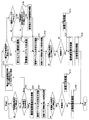
図20に、このようなミドルウェア挙動フローを示す。基本的な構成は実施例1にと同様だが、処理Aおよび処理Bは書込みもしくは読出し処理のいずれかを行うため、この判別機構によりフローが少々異なっている。そのため、処理起動時に、読出し処理か書込み処理化の条件分岐が入る。以降は実施例1のミドルウェア処理を踏襲する。本例において追加となるのは、書込み処理側において書込み可能領域が存在した場合である。この際に、管理メモリ領域数が3つ以上であり、かつ、予備領域が最新値を保持しておらず読出し中でもない場合に、解放可能となり、メモリ領域を管理表から削除する(S109)。
なお、本例では処理間でのデータ受渡し用に用いる固定的な2つのメモリ領域と、必要に応じて動的に確保/解放する1つの予備領域を用いる例について説明したが、2つのメモリ領域が常に確保されるのであれば、前述の固定的なメモリ領域としての形態は不要である。
すなわち、常に管理テーブル上に確保される2つのメモリ領域と、さらに必要に応じて動的に確保/解放される1つのメモリ領域、の構成でも、本実施例は実現可能である。この場合には、管理メモリ領域の解放条件は、管理アドレスが3つ以上であり、かつ、最新値を保持せず読出し中でもない、場合において、管理表からアドレス削除を行うことが可能となる。この場合には、S109処理が、当該メモリ領域を探索し削除、と変化する。
(実施例4)
以下、本発明に係る第4の実施例について図面を用いて説明する。
以下、本発明に係る第4の実施例について図面を用いて説明する。
産業系電子制御装置はセンサ情報の入力に基づき制御指令値を演算しアクチュエータを制御する構成が取られる。このような構成においては、周期的に動作するアクチュエータを正しく制御するため、一般的にセンサ入力から制御指令値出力までの間に実行時間制約が存在する。
一方で、マルチコア/メニーコアCPUにおける設計においては、前述の複数コア間におけるソフトウェア挙動は実行時のプロセッサ状態に応じて容易に変化し得ることから、例えば実行時間の変動が発生する。このような実行時間変動に対して、設計時におけるマージン設計などによる対処が取られるが、実行時間制約の厳しさや各種資源の競合により必ずしも処理完了が保証されるとは限らない。そのため、ミドルウェアに処理完了の確認と、未完了時の対処が必要となる。
図21に、処理Aの図中2回目の実行である処理A2が、実行時間変動の影響により規定の処理区間内に処理を完了できなかった例を示す。
本時刻同期型タイミング設計方式における、処理未完了時の対処としては以下の2つの方式が想定される。1つは、処理A2を強制的に中断もしくは実行終了させるケースである。対処法としては上位システムへ通知を行い、判断を仰ぐケースや、設計時にこのような違反発生ケースに対する処理が規定され、そちらに移行するケースも考えられるが、制御目的や実行時間制約違反時の影響範囲が小さいケースにおいては処理を継続するケースも想定される。
このような場合、ミドルウェアでは処理A2を中止し、かつメモリ管理テーブルを更新しないことで、処理A2の演算結果Res(A2)を用いるはずであった処理B4および処理B5が、演算未完了な値を用いないように制御する。これら処理は、処理A1の演算結果Res(A1)を用いて制御を継続する。
換言すれば、ミドルウェアを実行するプロセッサ(マルチコアプロセッサ1)は、複数の処理のそれぞれの終了時刻において、処理未完了を検出した場合に強制的に当該処理を停止させる未完了処理を行う。
もう1つの方式は、このようなケースにおいて、処理Aに対する処理Bのような、先行処理の結果を用いて処理を行う後続処理の設計時マージンを用いて処理Aの実行時間を延長することで、後続処理Bに最新の処理結果を渡す方式である。
換言すれば、ミドルウェアを実行するプロセッサ(マルチコアプロセッサ1)は、複数の処理のそれぞれの終了時刻において、処理未完了を検出した場合において、当該処理の演算結果を用いて演算を行う後続処理の開始時刻を、設計時に規定される猶予時間分だけ遅らせることにより、後続処理において最新の演算処理結果を用いて演算を継続する。
図21において、処理A2の後続処理である処理B4、およびコア数によっては処理A2の遅れの影響が自身の処理時間削減に繋がる処理A3の両者は、共にマージン時間、すなわち処理区間と各処理の実行時間との差分が存在する。この時間は通常、前述のようなマルチコア上における実行時間変動を吸収するために用いられるものであるが、設計時における最悪実行時間が常に発生するわけではないことから、同マージン時間を利用することは可能である。
本実施例においては、例えばマージン時間を最悪実行時間+20%と設計し、そのうち10%をこのような先行処理の遅れに対し適用可能であるとする。このような時間を、遅延吸収時間(図22)と呼ぶと、このような条件において、処理A2に遅延が発生した場合、影響を受ける処理(処理B4、および例えば2コアで本処理を行う場合には処理A3も含む)のうち、直近の遅延吸収時間終了時刻(同図における時刻T4)を、ミドルウェアがタスク情報などから取得し、同時刻まで処理A2を継続する。同時刻において処理A2が完了した場合には実施例3に記載のメモリ管理と同様の終了処理を実施し、同時刻においても処理A2が完了しない場合には、前述の1つめの方式と同様の強制終了処理を取る。
図23に、本実施例におけるミドルウェア挙動に関するフロー図を示す。上述の未完了時処理(S110)を追加することで、産業用制御装置に求められる実行時間制約に関し、特に制約違反の検出および対処方式が提供され、より幅広い産業用制御装置への本方式適用が実現される。
以上の構成により、産業用制御装置に求められる実時間制約に対し、本発明が準拠することが出来る。また上記に示した2つめの対処法においては、実時間制約に違反した場合においても、処理実行上のマージン時間を用いて対処可能となる場合において処理継続もしくは最新の処理結果を用いた処理継続を可能とすることで、産業用制御装置による制御演算継続およびその精度向上が実現される。
以上説明したように、第1~第4の実施例によれば、時刻同期型設計におけるアプリケーション間におけるデータ受渡の効率を高めることができる。
なお、本発明は上記した実施例に限定されるものではなく、様々な変形例が含まれる。例えば、上述した実施例は本発明を分かりやすく説明するために詳細に説明したものであり、必ずしも説明した全ての構成を備えるものに限定されるものではない。また、ある実施例の構成の一部を他の実施例の構成に置き換えることが可能であり、また、ある実施例の構成に他の実施例の構成を加えることも可能である。また、各実施例の構成の一部について、他の構成の追加・削除・置換をすることが可能である。
また、上記の各構成、機能等は、それらの一部又は全部を、例えば集積回路で設計する等によりハードウェアで実現してもよい。また、上記の各構成、機能等は、プロセッサがそれぞれの機能を実現するプログラムを解釈し、実行することによりソフトウェアで実現してもよい。各機能を実現するプログラム、テーブル、ファイル等の情報は、メモリや、ハードディスク、SSD(Solid State Drive)等の記録装置、または、ICカード、SDカード、DVD等の記録媒体に置くことができる。
なお、本発明の実施例は、以下の態様であってもよい。
複数のコアを含むプロセッサを有する電子制御装置であって、前記プロセッサは、異なる周期で動作する複数の処理を実行し、前記複数の処理を実行する前記複数のコアごとにそれぞれアクセス可能な複数のメモリ領域を備え、データ書込みを行う先行処理と、データ読出しを行う後続処理とがそれぞれアクセス可能な前記メモリ領域を、前記処理の進捗に応じて変更する電子制御装置において、最新の前記処理の結果が書き込まれておらず、かつ読出し中でない書込み可能な前記メモリ領域を探索し、書込み可能な前記メモリ領域が存在しない場合、新たな前記メモリ領域を確保し、新たな前記メモリ領域を前記処理の結果の書き込み先とすることで、前記先行処理から前記後続処理へ前記処理の結果を受け渡すこと、を特徴とする電子制御装置。
これにより、産業用制御装置に求められる時刻同期型設計におけるアプリケーション間におけるデータ受渡の効率を高めることが可能である。
1:マルチコアプロセッサ
2:CPUコア
21:L1キャッシュ
22:L2キャッシュ
3:内部バス
4:外部メモリ
5:センサ
2:CPUコア
21:L1キャッシュ
22:L2キャッシュ
3:内部バス
4:外部メモリ
5:センサ
Claims (9)
- 異なる周期で動作する複数の処理を実行する複数のコアを含むプロセッサと、
前記複数の処理を実行する前記複数のコアごとにそれぞれアクセス可能な複数のメモリ領域を含むメモリと、を備え、
データ書込みを行う先行処理とデータ読出しを行う後続処理とがそれぞれアクセス可能な前記メモリ領域を前記処理の進捗に応じて変更する電子制御装置であって、
前記プロセッサは、
最新の前記処理の結果が書き込まれておらず、かつ読出し中でない書込み可能な前記メモリ領域を探索し、書込み可能な前記メモリ領域が存在しない場合、新たな前記メモリ領域を確保し、新たな前記メモリ領域を前記処理の結果の書き込み先とすることで、前記先行処理から前記後続処理へ前記処理の結果を受け渡すこと、を特徴とする電子制御装置。 - 請求項1に記載の電子制御装置であって、
前記複数の処理のそれぞれの開始時刻および終了時刻においてタイマ割込みが入ること、を特徴とする電子制御装置。 - 請求項2に記載の電子演算装置であって、
前記メモリ領域は3つの異なるメモリ領域から構成されること、を特徴とする電子制御装置。 - 請求項2に記載の電子制御装置であって、
前記メモリ領域は2つの異なるメモリ領域から構成され、
前記プロセッサは、
書込み可能な前記メモリ領域が存在しない場合、新たな前記メモリ領域を確保すること、を特徴とする電子制御装置。 - 請求項4に記載の電子制御装置であって、
前記メモリ領域として3つ以上のメモリアドレスを有している条件において、
前記プロセッサは、
1つのメモリアドレスが最新の前記処理の結果の書込み先ではなく、かつ読出し中でもない場合において、前記1つのメモリアドレスを解放すること、を特徴とする電子制御装置。 - 請求項1に記載の電子制御装置であって、
前記メモリ領域の管理処理は、
前記プロセッサが専用のミドルウェアを実行することにより実現されること、を特徴とする電子制御装置。 - 請求項6に記載の電子制御装置であって、
前記ミドルウェアを実行する前記プロセッサは、
前記複数の処理のそれぞれの終了時刻において、処理未完了を検出した場合に強制的に当該処理を停止させる未完了処理を行うこと、を特徴とする電子制御装置。 - 請求項6に記載の電子制御装置であって、
前記ミドルウェアを実行する前記プロセッサは、
前記複数の処理のそれぞれの終了時刻において、処理未完了を検出した場合において、当該処理の演算結果を用いて演算を行う後続処理の開始時刻を、設計時に規定される猶予時間分だけ遅らせることにより、後続処理において最新の演算処理結果を用いて演算を継続すること、を特徴とする電子制御装置。 - 請求項1に記載の電子制御装置であって、
前記メモリ領域ごとの占有状況と前記処理の結果の最新値の有無を格納するテーブルを備え、
前記プロセッサは、
前記テーブルのすべての前記メモリ領域について、前記占有状況が専有を示し、または前記最新値の有無が最新値を格納していることを示す場合、書込み可能な前記メモリ領域が存在しないと判定すること、を特徴とする電子制御装置。
Applications Claiming Priority (2)
| Application Number | Priority Date | Filing Date | Title |
|---|---|---|---|
| JP2020117161A JP7425685B2 (ja) | 2020-07-07 | 2020-07-07 | 電子制御装置 |
| JP2020-117161 | 2020-07-07 |
Publications (1)
| Publication Number | Publication Date |
|---|---|
| WO2022009741A1 true WO2022009741A1 (ja) | 2022-01-13 |
Family
ID=79553102
Family Applications (1)
| Application Number | Title | Priority Date | Filing Date |
|---|---|---|---|
| PCT/JP2021/024626 Ceased WO2022009741A1 (ja) | 2020-07-07 | 2021-06-29 | 電子制御装置 |
Country Status (2)
| Country | Link |
|---|---|
| JP (1) | JP7425685B2 (ja) |
| WO (1) | WO2022009741A1 (ja) |
Cited By (2)
| Publication number | Priority date | Publication date | Assignee | Title |
|---|---|---|---|---|
| CN115878549A (zh) * | 2023-03-03 | 2023-03-31 | 上海聪链信息科技有限公司 | 核间通信系统 |
| WO2025022521A1 (ja) * | 2023-07-24 | 2025-01-30 | 日立Astemo株式会社 | 車載制御装置 |
Families Citing this family (1)
| Publication number | Priority date | Publication date | Assignee | Title |
|---|---|---|---|---|
| JP7773941B2 (ja) * | 2022-04-26 | 2025-11-20 | Astemo株式会社 | 電子制御装置 |
Citations (2)
| Publication number | Priority date | Publication date | Assignee | Title |
|---|---|---|---|---|
| WO2010119932A1 (ja) * | 2009-04-17 | 2010-10-21 | 日本電気株式会社 | マルチプロセッサシステム、マルチプロセッサシステムにおけるメモリ管理方法及び通信プログラム |
| JP2010244096A (ja) * | 2009-04-01 | 2010-10-28 | Seiko Epson Corp | データ処理装置、印刷システムおよびプログラム |
-
2020
- 2020-07-07 JP JP2020117161A patent/JP7425685B2/ja active Active
-
2021
- 2021-06-29 WO PCT/JP2021/024626 patent/WO2022009741A1/ja not_active Ceased
Patent Citations (2)
| Publication number | Priority date | Publication date | Assignee | Title |
|---|---|---|---|---|
| JP2010244096A (ja) * | 2009-04-01 | 2010-10-28 | Seiko Epson Corp | データ処理装置、印刷システムおよびプログラム |
| WO2010119932A1 (ja) * | 2009-04-17 | 2010-10-21 | 日本電気株式会社 | マルチプロセッサシステム、マルチプロセッサシステムにおけるメモリ管理方法及び通信プログラム |
Cited By (2)
| Publication number | Priority date | Publication date | Assignee | Title |
|---|---|---|---|---|
| CN115878549A (zh) * | 2023-03-03 | 2023-03-31 | 上海聪链信息科技有限公司 | 核间通信系统 |
| WO2025022521A1 (ja) * | 2023-07-24 | 2025-01-30 | 日立Astemo株式会社 | 車載制御装置 |
Also Published As
| Publication number | Publication date |
|---|---|
| JP7425685B2 (ja) | 2024-01-31 |
| JP2022014679A (ja) | 2022-01-20 |
Similar Documents
| Publication | Publication Date | Title |
|---|---|---|
| US7543295B2 (en) | Method for enhancing efficiency in mutual exclusion | |
| US7890725B2 (en) | Bufferless transactional memory with runahead execution | |
| US8825923B2 (en) | Memory system having high data transfer efficiency and host controller | |
| US7945741B2 (en) | Reservation required transactions | |
| US12222859B2 (en) | Write data cache method and system, device, and storage medium | |
| CN104094233A (zh) | 车辆用控制装置 | |
| CN118377637B (zh) | 减少冗余缓存一致性操作的方法、装置、设备和存储介质 | |
| CN105094084B (zh) | 支持多核控制器上的相干数据访问的服务和系统 | |
| JP2000020320A (ja) | コンパイル方法、例外処理方法、及びコンピュータ | |
| JP7425685B2 (ja) | 電子制御装置 | |
| CN114780248B (zh) | 资源访问方法、装置、计算机设备及存储介质 | |
| US20060149940A1 (en) | Implementation to save and restore processor registers on a context switch | |
| JPWO2010097925A1 (ja) | 情報処理装置 | |
| JP2011129104A (ja) | 適応的最適化された比較/交換オペレーション | |
| CN114741036A (zh) | 一种异构多核处理器下日志管理的方法 | |
| JP5999216B2 (ja) | データ処理装置 | |
| CN113946445A (zh) | 一种基于asic的多线程模块及多线程控制方法 | |
| US20030014558A1 (en) | Batch interrupts handling device, virtual shared memory and multiple concurrent processing device | |
| JP2022092692A (ja) | 電子制御装置及びタスク実行制御方法 | |
| JP2009175960A (ja) | 仮想マルチプロセッサシステム | |
| JP4755232B2 (ja) | コンパイラ | |
| CN121166607B (zh) | 基于位图的内存管理方法、内存管理单元、系统及介质 | |
| US20260044371A1 (en) | Task stealing method and apparatus, chip, and computer device | |
| JP2003131893A (ja) | 演算処理システム、コンピュータ・システム上でのタスク制御方法、並びに記憶媒体 | |
| JP2021060758A (ja) | 車両制御装置 |
Legal Events
| Date | Code | Title | Description |
|---|---|---|---|
| 121 | Ep: the epo has been informed by wipo that ep was designated in this application |
Ref document number: 21838271 Country of ref document: EP Kind code of ref document: A1 |
|
| NENP | Non-entry into the national phase |
Ref country code: DE |
|
| 122 | Ep: pct application non-entry in european phase |
Ref document number: 21838271 Country of ref document: EP Kind code of ref document: A1 |