WO2022009489A1 - 行動認識装置、行動認識方法、及びプログラム - Google Patents
行動認識装置、行動認識方法、及びプログラム Download PDFInfo
- Publication number
- WO2022009489A1 WO2022009489A1 PCT/JP2021/014244 JP2021014244W WO2022009489A1 WO 2022009489 A1 WO2022009489 A1 WO 2022009489A1 JP 2021014244 W JP2021014244 W JP 2021014244W WO 2022009489 A1 WO2022009489 A1 WO 2022009489A1
- Authority
- WO
- WIPO (PCT)
- Prior art keywords
- action
- behavior
- recognition
- candidate
- information
- Prior art date
- Legal status (The legal status is an assumption and is not a legal conclusion. Google has not performed a legal analysis and makes no representation as to the accuracy of the status listed.)
- Ceased
Links
Images






Classifications
-
- G—PHYSICS
- G06—COMPUTING OR CALCULATING; COUNTING
- G06V—IMAGE OR VIDEO RECOGNITION OR UNDERSTANDING
- G06V20/00—Scenes; Scene-specific elements
- G06V20/50—Context or environment of the image
- G06V20/52—Surveillance or monitoring of activities, e.g. for recognising suspicious objects
-
- G—PHYSICS
- G06—COMPUTING OR CALCULATING; COUNTING
- G06T—IMAGE DATA PROCESSING OR GENERATION, IN GENERAL
- G06T7/00—Image analysis
-
- G—PHYSICS
- G06—COMPUTING OR CALCULATING; COUNTING
- G06T—IMAGE DATA PROCESSING OR GENERATION, IN GENERAL
- G06T7/00—Image analysis
- G06T7/20—Analysis of motion
-
- G—PHYSICS
- G06—COMPUTING OR CALCULATING; COUNTING
- G06V—IMAGE OR VIDEO RECOGNITION OR UNDERSTANDING
- G06V10/00—Arrangements for image or video recognition or understanding
- G06V10/40—Extraction of image or video features
- G06V10/44—Local feature extraction by analysis of parts of the pattern, e.g. by detecting edges, contours, loops, corners, strokes or intersections; Connectivity analysis, e.g. of connected components
- G06V10/443—Local feature extraction by analysis of parts of the pattern, e.g. by detecting edges, contours, loops, corners, strokes or intersections; Connectivity analysis, e.g. of connected components by matching or filtering
- G06V10/449—Biologically inspired filters, e.g. difference of Gaussians [DoG] or Gabor filters
- G06V10/451—Biologically inspired filters, e.g. difference of Gaussians [DoG] or Gabor filters with interaction between the filter responses, e.g. cortical complex cells
- G06V10/454—Integrating the filters into a hierarchical structure, e.g. convolutional neural networks [CNN]
-
- G—PHYSICS
- G06—COMPUTING OR CALCULATING; COUNTING
- G06V—IMAGE OR VIDEO RECOGNITION OR UNDERSTANDING
- G06V10/00—Arrangements for image or video recognition or understanding
- G06V10/70—Arrangements for image or video recognition or understanding using pattern recognition or machine learning
- G06V10/82—Arrangements for image or video recognition or understanding using pattern recognition or machine learning using neural networks
-
- G—PHYSICS
- G06—COMPUTING OR CALCULATING; COUNTING
- G06V—IMAGE OR VIDEO RECOGNITION OR UNDERSTANDING
- G06V20/00—Scenes; Scene-specific elements
- G06V20/70—Labelling scene content, e.g. deriving syntactic or semantic representations
-
- G—PHYSICS
- G06—COMPUTING OR CALCULATING; COUNTING
- G06V—IMAGE OR VIDEO RECOGNITION OR UNDERSTANDING
- G06V40/00—Recognition of biometric, human-related or animal-related patterns in image or video data
- G06V40/10—Human or animal bodies, e.g. vehicle occupants or pedestrians; Body parts, e.g. hands
- G06V40/16—Human faces, e.g. facial parts, sketches or expressions
- G06V40/161—Detection; Localisation; Normalisation
-
- G—PHYSICS
- G06—COMPUTING OR CALCULATING; COUNTING
- G06V—IMAGE OR VIDEO RECOGNITION OR UNDERSTANDING
- G06V40/00—Recognition of biometric, human-related or animal-related patterns in image or video data
- G06V40/20—Movements or behaviour, e.g. gesture recognition
Definitions
- This disclosure relates to a technology for recognizing user behavior in a building.
- Patent Document 1 discloses a technique of detecting a human region including a human from a moving image and recognizing a human behavior from a combination of a human posture reflected in the region and a surrounding object.
- Patent Document 2 discloses a technique of extracting skeleton information based on a human joint from a moving image in chronological order, extracting an enclosed area of the skeleton information, and recognizing a human behavior from the extracted enclosed area. There is.
- Patent Document 1 since the floor plan information of the building is not taken into consideration, it is necessary to improve in order to accurately recognize the behavior of the person who depends on the space in the building. ..
- the behavior recognition device is a behavior recognition device that recognizes a person's behavior in a building, and includes target behavior information including one or more target behaviors to be recognized in advance, and the building.
- the first acquisition unit that acquires the layout information and the position information of the image sensor installed in the building, and the one or more included in the target behavior information based on the position information of the image sensor and the layout information.
- An action selection unit that selects a candidate behavior that is a recognition candidate from the target behavior, a second acquisition unit that acquires image data detected by the image sensor, and one or more recognizers corresponding to the candidate behavior are determined.
- the first action recognition unit that calculates the feature amount of the image data using the one or more recognizers, the second action recognition unit that recognizes the candidate action based on the feature amount, and the second action recognition. It is provided with an output unit that outputs the recognition result by the unit.
- FIG. 1 It is a figure which shows an example of the interaction between a user and a display terminal in a scene where an image sensor is installed at the entrance. It is a figure which shows the interaction following FIG. It is a figure which shows an example of the setting screen on which the annotation image is superimposed. It is a figure which shows the scene which the image sensor is installed in the kitchen. It is a figure which shows an example of the interaction between a user and a display terminal in a scene where an image sensor is installed in a kitchen. It is a figure which shows the interaction following FIG. It is a figure which shows an example of the setting screen on which the annotation image is superimposed. It is a figure which shows an example of the interaction between a user and a display terminal when correcting an annotation image after installing an image sensor. It is a figure which shows an example of the setting screen which superposed and displayed the annotation image.
- Patent Document 1 a human behavior is recognized in consideration of a combination of a human posture and an object around the human, but an object unrelated to the human behavior is reflected around the human. If so, the object is not useful information for estimating human behavior. Therefore, in Patent Document 1, further improvement is required to recognize the behavior of a person who depends on space.
- Patent Document 2 As is clear from the fact that the human behavior is estimated from the enclosed area of the skeleton information, the behavior that does not depend on the background is assumed as the behavior to be recognized. Therefore, in Patent Document 2, further improvement is required to estimate behavior that strongly depends on space, such as cooking behavior performed in the kitchen.
- the present inventor has obtained the finding that the behavior of a person depending on the space in the building can be accurately recognized if the floor plan information of the building is taken into consideration, and conceives each aspect of the present disclosure shown below. I arrived.
- the behavior recognition device is a behavior recognition device that recognizes a person's behavior in a building, and includes target behavior information including one or more target behaviors to be recognized in advance, and the building.
- the first acquisition unit that acquires the layout information and the position information of the image sensor installed in the building, and the one or more included in the target behavior information based on the position information of the image sensor and the layout information.
- An action selection unit that selects a candidate behavior that is a recognition candidate from the target behavior, a second acquisition unit that acquires image data detected by the image sensor, and one or more recognizers corresponding to the candidate behavior are determined.
- the first action recognition unit that calculates the feature amount of the image data using the one or more recognizers, the second action recognition unit that recognizes the candidate action based on the feature amount, and the second action recognition. It is provided with an output unit that outputs the recognition result by the unit.
- a candidate behavior to be recognized is selected from the target behaviors based on the position information of the image sensor and the floor plan information of the building, and the recognition result for the candidate behavior is calculated. Therefore, it is possible to accurately recognize the behavior of a person who depends on the space in the building.
- the first action recognition unit determines a recognizer according to the candidate action, calculates the feature amount of the image data using the determined recognizer, and performs the second action from the calculated feature amount.
- the recognizer recognizes the candidate behavior. Therefore, it becomes possible to use an existing recognizer as a recognizer, and it becomes easy to construct a behavior recognition device. Furthermore, since the feature amount is calculated using one or more recognizers corresponding to the candidate behavior, it is possible to calculate the feature amount suitable for recognizing the candidate behavior, and it is possible to improve the recognition accuracy of the target behavior. It will be possible.
- the first action recognition unit determines a plurality of recognizers when the candidate action is a predetermined action, and the second action recognition unit is calculated by each of the plurality of recognizers.
- the feature quantities may be combined and the candidate behavior may be recognized based on the combined feature quantities.
- the target behavior is a predetermined behavior
- a plurality of recognizers are determined. Therefore, for example, when the predetermined behavior depends on an object around the person, the feature amount of the person. It is possible to calculate the feature amount by using the recognizer that calculates the feature amount and the recognizer that calculates the feature amount of the object, and it is possible to improve the recognition accuracy of the candidate action.
- the feature amounts calculated by each recognizer are combined, and the target behavior is recognized based on the combined feature amounts. Therefore, when a plurality of feature quantities are calculated by a plurality of recognizers, it is possible to combine them with one feature quantity and input them to the second action recognition unit, which simplifies the configuration of the behavior recognition device. It will be possible.
- the predetermined behavior may be cleaning, brushing teeth, cooking, washing, using a computer, reading, or eating.
- each recognizer is composed of a convolutional neural network (hereinafter referred to as CNN), and the second behavior recognition unit includes a logistics regression, a support vector machine, a decision tree, a random forest, and k-nearest neighbors.
- the candidate behavior may be recognized using a classifier using any one of the method, Gaussian naive bays, perceptron, and stochastic descent method.
- each recognizer is composed of CNN
- the second action recognizer is composed of a classifier using logistic regression or the like, so that the processing cost is lower than that of the first action recognition unit. It is possible to configure the second action recognizer.
- the second behavior recognition unit may recognize the candidate behavior using a classifier machine-learned with the feature amount as an explanatory variable and the target behavior as an objective variable.
- the second behavior recognition unit is configured by using the classifier generated by machine learning with the feature amount calculated by each recognizer as the explanatory variable and the candidate action corresponding to the feature amount as the objective variable. can do. For example, if the classifier is configured with a classifier having a smaller processing load than the CNN such as the logistic regression described above, the classifier can be trained in a short time. Further, by configuring the first behavior recognition unit with an existing recognizer composed of CNN, it is possible to configure the behavior recognition device without machine learning only the second behavior recognition unit and machine learning of the first behavior recognition unit. ..
- the second action recognition unit weights each feature amount using a weighting coefficient predetermined according to the candidate action, and performs the candidate action based on each weighted feature amount. You may recognize it.
- each feature amount is weighted according to the target action, and the candidate action is recognized based on each weighted feature amount, so that the candidate action can be accurately recognized.
- one or more objects installed in the building are extracted from the floor space information, and the one or more objects are used as a movable first object, a second object that is a water supply facility, and the above. It is classified into one of the third objects that are the structures of the building, and for each of the above-mentioned one or more objects, the flooring feature amount in which the classification information indicating the classification result and the installation position are associated with each other is extracted, and the flooring feature is extracted.
- An action selection table is generated based on the quantity, and the action selection table is a table in which one or more spaces of the building and the target action corresponding to each space are associated with each other, and the first acquisition unit. May acquire the action selection table as the target action information.
- the floor plan feature amount in which the classification information and the installation position are associated is extracted based on the floor plan information. Therefore, it is possible to grasp what kind of object is installed in each space in the building, and it is possible to extract useful information for creating an action selection table. Then, an action selection table in which each space of the building and the target action corresponding to each space are associated with each other is generated based on the floor plan feature amount, and the action selection table is acquired as the target action information. Therefore, the relationship between each space and the target behavior can be quickly grasped, and the candidate behavior can be easily selected.
- the behavior recognition device is communicably connected to a display terminal, acquires the name of the space of the building in which the image sensor is installed via the display terminal, and is a specific device related to the space.
- an installation support unit that outputs an installation guidance for installing the image sensor to a display terminal so that the specific equipment is included in the field of view of the image sensor may be further provided.
- the installation guidance for installing the image sensor is output to the display terminal so that the specific device or the specific equipment related to the space is included in the field of view of the image sensor, so that the user can appropriately use the image sensor. Can be installed. Further, since the name of the space of the building is acquired via the display terminal, the image sensor and the space in which the image sensor is installed can be associated with each other. As a result, the candidate action can be easily selected by referring to the installation position of the image sensor and the action selection table.
- the installation support unit acquires image data taken by the image sensor, detects the specific device or the specific equipment included in the image data, and detects the specific device or the specific equipment.
- the annotation image showing the result may be superimposed and displayed on the image shown by the image data.
- the annotation image which is the detection result of the specific device or the specific equipment detected from the image data is superimposed and displayed on the image indicated by the image data. Therefore, it is possible to easily confirm whether the specific device or the specific equipment is correctly detected from the image data.
- the installation support unit may acquire the correction instruction of the annotation image via the display terminal and store the annotation information indicated by the corrected annotation image in the memory.
- the instruction to correct the annotation information is acquired via the display terminal. Therefore, for example, when the recognizer cannot correctly detect the specific device or the specific equipment, the position of the specific device or the specific equipment is accurately indicated.
- the annotation information can be modified as follows. Further, it is possible to make the recognizer grasp the position on the image of the specific device or the specific equipment which is important for recognizing the target behavior.
- the present disclosure can also be realized as a behavior recognition method in which a computer executes each characteristic configuration included in such a behavior recognition device and a behavior recognition program in which a computer executes each characteristic configuration.
- an action recognition program can be distributed via a computer-readable non-temporary recording medium such as a CD-ROM or a communication network such as the Internet.
- Computer-based methods of recognizing human behavior are classified into three types according to the relationship between people and the space in which they are located.
- the first type is a method of recognizing behavior unrelated to the space in which a person is located. For example, behaviors such as walking or standing are expressed only by the movement of the person of interest and are irrelevant to the space in which the person is.
- the second type is a method of recognizing behaviors involved with an object existing in the space where a person is present or an object located near the person. For example, the behavior of riding a bicycle can be recognized by combining human posture detection and object detection. When recognizing the behavior of a person involved in an object outdoors or the like, it is difficult to grasp the structure of the building or the condition of the road in advance.
- the third type is a method of recognizing behavior by grasping both a person and a space in which the person is. For example, the behavior of starting cooking in the kitchen can be recognized by a person being present in the kitchen and facing the microwave.
- the behavior of the person to be recognized by the present embodiment includes, for example, behavior accompanied by movements such as starting cooking and cleaning, as well as behaviors without movements such as watching TV while sleeping.
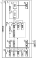
- FIG. 1 is a block diagram showing an example of the configuration of the behavior recognition device 1 according to the embodiment.
- the action recognition device 1 is a device that recognizes a user's action in the user's house (an example of a building).
- the action recognition device 1 is composed of, for example, a computer including a processor, a memory, an interface circuit, and the like.
- the behavior recognition device 1 does not have to be realized by a single computer, but may be realized by a distributed processing system (not shown) including a terminal device and a server.
- the behavior recognition device 1 may be configured by providing a memory for storing the image data 204 in the terminal device in the house and providing a part or all the blocks constituting the processor 100 in the server. This form will be described with reference to a modification described later.
- the action recognition device 1 includes a processor 100 and a memory 200.
- the memory 200 is composed of a non-volatile storage device such as SSD or HHD, and stores target action information 201, layout information 202, position information 203, image data 204, and list information 205.
- the memory 200 may store the image data 204 acquired from the image sensor 2 at a predetermined frame rate by the second acquisition unit 103 for a certain period of time (for example, 1 minute) retroactively from the present to the past.
- the image sensor 2 is composed of, for example, a camera installed in the house.
- the image sensor 2 acquires the image data 204 by photographing the space in the house at a predetermined frame rate, and inputs the image data 204 to the second acquisition unit 103.
- the image data 204 may be, for example, color image data or monochrome image data.
- the processor 100 is composed of an electric circuit such as a CPU.
- the processor 100 includes a first acquisition unit 101, an action selection unit 102, a second acquisition unit 103, a first action recognition unit 104, a second action recognition unit 105, and an output unit 106.
- Each of these blocks is realized by the processor 100 executing, for example, an action recognition program. However, this is an example, and each of these blocks may be realized by a dedicated hardware circuit such as an ASIC.
- the first acquisition unit 101 acquires the target action information 201 indicating the target action to be recognized in advance and stores it in the memory 200.
- the first acquisition unit 101 may acquire the target action information 201 input through the registration work using the input device (illustrated).
- the input device is composed of, for example, a keyboard, a mouse, and the like.
- the target behavior information 201 may be stored in the memory 200 in advance.
- the target action is, for example, various actions such as wiping and sweeping registered in the action selection table T1 shown in FIG.
- the target behavior information 201 may be stored in the memory 200 in advance.
- the action selection table T1 is an example of the target action information 201.
- the first acquisition unit 101 acquires the floor plan information 202 in the house and stores it in the memory 200.
- the floor plan information 202 is two-dimensional or three-dimensional information expressing the components of a room such as a living room, a dining room, and a kitchen, and the shape and positional relationship of each room.
- the layout information 202 is, for example, two-dimensional drawing data describing the layout, three-dimensional design data (CAD data) used for housing design, and three-dimensional point cloud information (point cloud) in the house measured by a three-dimensional laser scanner. It is composed of track information of a device moving in the house such as a cleaning robot, video data in the house taken by a calibrated camera, or information acquired from a device having information on an installed room.
- the first acquisition unit 101 acquires the position information 203 of the image sensor 2 installed in the house and stores it in the memory 200.
- the position information 203 is composed of coordinate data represented by a coordinate system of a two-axis or three-axis coordinate space included in the floor plan information 202, for example.
- the first acquisition unit 101 acquires the position information 203 input by the registration operation using, for example, the input device (not shown).
- the action selection unit 102 selects a candidate action as a recognition candidate from the target actions based on the position information 203 of the image sensor 2 and the floor plan information 202. For example, the action selection unit 102 identifies a space in the house where the image sensor 2 is installed from the position information 203 and the floor plan information 202, and performs a predetermined action in which the user is estimated to act in the specified space. select. Specifically, the action selection unit 102 may determine the action corresponding to the specified space by referring to the action selection table T1 shown in FIG.
- the space is, for example, a space constituting a house such as a room, an entrance, and a kitchen.
- the second acquisition unit 103 acquires the image data 204 taken by the image sensor 2 at a predetermined frame rate and stores it in the memory 200.
- the first action recognition unit 104 determines one or more recognizers corresponding to the candidate actions selected by the action selection unit 102, and calculates the feature amount of the image data 204 using the determined recognizers.
- the first action recognition unit 104 includes a recognizer selection unit 110 and N (N is an integer of 1 or more) recognizers 111_1, 111_2, ... 111_N.
- N is an integer of 1 or more
- recognizers 111_1, 111_2, ... 111_N are generically referred to, they are referred to as the recognizer 111.
- the recognizer selection unit 110 selects the recognizer 111 used for recognizing the candidate action selected by the action selection unit 102. For example, the recognizer selection unit 110 selects the recognizer 111 corresponding to the candidate action by referring to the recognizer selection table T2 shown in FIG. 5 when the list information 205 described later is generated, and will be described later when the recognition process is executed. The recognizer 111 for the candidate action may be selected by referring to the list information 205.
- the recognizer 111 is, for example, a recognizer configured by CNN.
- the first action recognition unit 104 individually recognizes each of posture estimation, object detection, face detection, head orientation estimation, age / gender estimation, individual estimation, and tracking. Includes recognizer 111.
- These recognizers 111 are diversions or partial modifications of existing recognizers whose source code has been released.
- the feature amount differs depending on the recognizer 111.
- the feature amount calculated by the posture estimation recognizer 111 includes, for example, two-dimensional coordinate data representing each of a plurality of feature points (for example, 17 points such as the right shoulder and the right elbow) constituting the skeleton information. ..
- the feature amount calculated by the object detection recognizer 111 includes, for example, the coordinate data of the circumscribing rectangle surrounding the object and the label of the recognized object.
- the object detected by the object detection is given, and for example, 80 kinds of objects in the house (microwave oven, refrigerator, etc.) are detected.
- the feature amount calculated by the face detection recognizer 111 includes, for example, image data of a face region in which a face is surrounded by an extrinsic rectangle.
- the feature amount calculated by each recognizer 111 is not data that cannot be understood by humans (for example, a tensor) as output from the intermediate layer of DNN.
- the first action recognition unit 104 includes a recognizer 111 that depends on another recognizer 111 according to the candidate action.
- the dependent recognizer 111 is a recognizer 111 in which a feature amount calculated by another recognizer 111 is input and the feature amount is calculated by using the feature amount.
- the head orientation estimation recognizer 111 calculates a feature amount indicating the head orientation using the feature amount (image data of the face region) calculated by the face detection recognizer 111.
- the second action recognition unit 105 recognizes each candidate action selected by the action selection unit 102 based on the feature amount calculated by each recognizer 111.
- the second action recognition unit 105 includes a coupler 121 and a classifier 122.
- the combiner 121 combines the feature amounts calculated by each combiner 121, and inputs the combined feature amounts to the classifier 122.
- the coupler 121 may weight each feature amount using a weighting coefficient determined in advance according to the candidate behavior, and may concatenate the weighted feature amounts and input to the classifier 122.
- the classifier 122 recognizes the candidate behavior by calculating the likelihood for the candidate behavior based on the feature amount input from the coupler 121.
- the classifier 122 is composed of a classifier for classifying.
- the classifier 122 is composed of, for example, a classifier using any one of logistic regression, support vector machine, decision tree, random forest, k-nearest neighbor method, Gaussian naive Bayes, perceptron, and stochastic descent method. When there are a plurality of candidate behaviors, the classifier 122 calculates the likelihood for each candidate behavior.
- the classifier 122 is machine-learned with the feature amount output from the recognizer 111 as an explanatory variable and the target behavior as an objective variable. This machine learning is performed individually for each target behavior. For example, when the target behavior is "start cooking", the combination result of the feature amount output from each recognizer 111 used for this target behavior is used as an explanatory variable, and "start cooking” is used as an objective variable. Machine learning is performed.
- the output unit 106 outputs the recognition result of the second action recognition unit 105. Specifically, the output unit 106 outputs a recognition result for human behavior based on the likelihood calculated by the classifier 122. For example, when there are a plurality of candidate actions, the classifier 122 may output the label having the maximum likelihood as the recognition result.
- the recognition result is output to an external device (not shown) via, for example, a communication circuit.
- the external device may be, for example, a home appliance installed in the house and performing control based on the recognition result.
- This home electric appliance may be, for example, a display device installed in a house and displaying a recognition result.
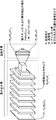
- FIG. 2 is an explanatory diagram of the CNN constituting the recognizer 111.
- the CNN includes a convolutional layer and a fully connected layer.
- the CNN is composed of 9 convolutional layers and 2 fully connected layers.
- the input layer of the input image data D1 is the 0th layer
- the convolution layer is the 1st to 9th layers
- the fully connected layer is the 10th to 11th layers
- the output layer is the 12th layer.
- the input image data D1 is represented by H0 ⁇ W0 ⁇ C0.
- H indicates the height of the data in each layer
- W indicates the width of the data in each layer
- C indicates the number of channels in each layer.
- the feature amount of the data of each layer is calculated by the convolution operation.
- the data output from the convolution layer is collected and the output data is generated.
- P ⁇ M ⁇ 2 (x, y) data are output as output data from the fully connected layer.
- the CNN has very high recognition accuracy for image data.
- the CNN is composed of many layers such as a convolution layer and a fully connected layer, the processing load is high and it takes a lot of time to learn.
- the classifier 122 is a classifier such as a support vector machine whose processing load is significantly lower than that of CNN. Therefore, in the present embodiment, the existing recognizer is used as the recognizer 111 composed of CNNs, and the classifier 122 having a low processing load is made to learn the target behavior. As a result, the learning time can be shortened, and the behavior recognition device 1 can be easily constructed.
- FIG. 3 is a diagram showing an example of the configuration of the first action recognition unit 104.
- the first action recognition unit 104 includes a recognition device 111_1 for posture estimation, a recognition device 111_2 for object detection, a recognition device 111_3 for face detection, and a recognition device 111_4 for head orientation estimation.
- Input image data D1 is input to each of the recognizers 111_1 to 111_3.
- the input image data D1 is image data in the house taken by the image sensor 2.
- the input image data D1 includes a scene in which a person stands facing the refrigerator in the kitchen.
- the recognizer 111_1 outputs coordinate data constituting the skeleton information of the standing posture as a feature amount.
- the recognizer 111_2 detects a given object from the input image data D1, and outputs the coordinate data of the vertices of the circumscribing rectangle surrounding the detected object and the label of the detected object as feature quantities.
- the refrigerator is detected as an object.
- the recognizer 111_3 detects a human face from the input image data D1 and outputs the image data of the face area in which the detected face is surrounded by the circumscribing rectangle as a feature amount.
- the recognizer 111_4 estimates the head orientation of a person from the image data of the face area output from the recognizer 111_3.
- the head orientation is represented by, for example, a direction vector starting from the center of gravity of the face region.
- the second action recognition unit 105 determines that a person is facing the refrigerator, for example, when the center of gravity of the circumscribing rectangle surrounding the refrigerator is in the direction of the direction vector. For example, the second action recognition unit 105 rotates the direction vector on the image within a range of plus or minus threshold angles (for example, plus or minus 30 degrees), and the extension line of the direction vector passes through the center of gravity of the refrigerator. In that case, the person determines that he or she faces the refrigerator.
- plus or minus threshold angles for example, plus or minus 30 degrees
- the second action recognition unit 105 can determine the action of "starting cooking".
- the recognizer 111_4 may detect the direction of the line of sight, the direction of the nose, and the normal direction of the body instead of the head direction.
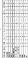
- FIG. 4 is a diagram showing an example of the configuration of the action selection table T1.
- the action selection table T1 stores a plurality of spaces in association with each other and the target action to be recognized for each of the spaces.
- Target actions include wiping, sweeping, brushing teeth, starting cooking, brewing coffee, using a laptop (notebook), washing, reading, eating, and walking.
- the entrance, kitchen, living room, dining room, bedroom, bathroom, and washroom are adopted.
- these are examples, and other spaces and target behaviors may be adopted.
- a target behavior such as lying on the sofa and watching TV may be assigned to the living room.
- the ⁇ mark indicates that the corresponding target action is the recognition target for the corresponding space.
- the x mark indicates that the corresponding target behavior is not recognized as the recognition target for the corresponding space.
- the wiping cleaning shown in the first line is a recognition target in the entrance, kitchen, living room, dining room, bathroom, and washroom.
- Toothpaste is an activity that takes place in the space around the water and is therefore recognized in kitchens, bathrooms, and washrooms.
- Coffee brewing is recognized for kitchens and dining because coffee makers can be placed not only in the kitchen but also in the dining room.
- laptops are subject to recognition in these spaces as laptops may be used in dining, living and bedrooms.
- Laundry is subject to recognition in the washroom, assuming that the washing machine will be installed in the washroom. Reading is likely to be done in the space where a person sits, so it is recognized in the living room, dining room, and bedroom. Since meals may be served not only in the dining room but also in the living room, they are recognized in the living room and dining room. Since walking is performed in all spaces, it is a recognition target in all spaces.
- the action selection unit 102 can select the target action corresponding to the space by referring to such an action selection table T1, it is possible to easily select an appropriate target action for the space.
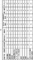
- FIG. 5 is a diagram showing an example of the configuration of the recognizer selection table T2.
- the recognizer selection table T2 stores a plurality of target actions in association with each other and the recognizer 111 used when recognizing each target action.
- the ⁇ mark indicates the recognizer 111 used for the corresponding target action
- the ⁇ mark indicates the recognizer not used for the corresponding target action.
- the target behavior is the same as the target behavior shown in FIG. Posture estimation, object detection, face detection, head orientation estimation, age gender estimation, individual estimation, and tracking are each performed individually by the corresponding recognizer 111.
- the attitude estimation, object detection, and tracking recognizer 111 is used for the same reason as wiping. Since individual identification and movement are not important for toothpaste, a recognizer 111 other than age-gender estimation, individual estimation, and tracking is used.
- All recognizers 111 are used to start cooking. For example, since it is assumed that the mother often cooks, at the start of cooking, the age-gender estimation and personal estimation recognizers 111 are used to estimate whether or not the mother is a mother.
- Coffee brewing is different from starting cooking, it is assumed that a father or a child will be brewed, and movement is not important, so a recognizer 111 other than age / gender estimation, personal estimation, and tracking is used.
- a recognizer 111 other than tracking is used.
- a recognizer 111 other than tracking is used. Since reading does not require individual identification and does not move, a recognizer 111 other than age / gender estimation, individual estimation, and tracking is used.
- Posture estimation and tracking recognizer 111 is used because walking does not involve objects and head orientation and individual identification are not important. When detecting an unknown behavior other than the above, all recognizers 111 are used.
- Posture estimation is effective for recognizing all target behaviors because it is possible to detect postures according to the target behaviors.
- face detection is required for head orientation estimation. That is, head orientation detection depends on face detection.
- object detection is effective for detecting cleaning tools such as vacuum cleaners, and tracking is effective because cleaning is performed while moving to multiple locations.
- object detection and tracking are as effective as wiping.
- object detection is effective for detecting toothbrushes and mirrors, and the direction of the head tends to face the direction of the mirror, so head orientation estimation is effective.
- object detection is effective for detecting cooking utensils and ingredients
- head orientation estimation is effective because the head orientation tends to face the kitchen or sink.
- age and gender estimation and individual estimation are effective for identifying individuals who cook frequently, such as mothers cooking well, and they may move from the sink to the stove in the kitchen. Tracking is enabled.
- object detection is effective for detecting coffee makers and coffee cups
- head orientation estimation is effective for detecting whether or not the head is facing the coffee maker.
- object detection is effective for detecting the notebook PC
- head orientation estimation is effective for detecting whether or not the head is facing the notebook PC
- the notebook PC should be used at work. Therefore, age, gender and individual estimation are effective.
- object detection is effective for detecting the washing machine
- head orientation estimation is effective for detecting whether or not the head is facing the washing machine
- an individual whose mother often does the laundry is effective for identifying.
- object detection is effective for detecting books
- head orientation estimation is effective for detecting whether or not the head is facing the book.
- object estimation is effective for detecting food.
- tracking is effective for capturing continuous movements.
- the target behavior that the behavior recognition device 1 recognizes is related to the space. For example, "start cooking” is strongly related to the space of the kitchen, and the information in this space is useful for behavior recognition. That is, if the target behavior is weighted to a specific object, head orientation, or the like, the detection accuracy of the target behavior is further improved. Therefore, in the present embodiment, the coupler 121 sets a weighting coefficient according to the target behavior as the feature amount.
- FIG. 6 is a diagram showing an example of a weight table T3 that the coupler 121 refers to when setting a weighting coefficient for a feature amount.
- the weight table T3 corresponds to a plurality of target actions, a class index for each target action, a label, spatial information, object information, heading information, spatial information weighting coefficient Wr, object information weighting coefficient We, and weighting contents. Attach and memorize.
- the target behavior wiping and cleaning is exemplified in addition to starting the cooking illustrated in FIG.
- records relating to each target behavior illustrated in FIG. 4 are also registered in the weight table T3.
- the class index is an index uniquely assigned to each target action.
- the class indexes are given by serial numbers.
- the label is a label of the target action output by the output unit 106.
- start cooking and "wiping” are exemplified as labels.
- labels for each target behavior illustrated in FIG. 4 are registered in the weight table T3.
- Spatial information is information on the space in which the target action is performed.
- a space for the target action defined in the action selection table T1 is registered, such as a kitchen for "start cooking”.
- Object information is information indicating an object related to the corresponding target behavior.
- the object information for "start cooking” corresponds to at least one of a refrigerator, a microwave oven, a gas stove, and an oven.
- the head orientation information is information indicating the relationship between the object described in the object information and the head orientation.
- the head-to-head information for "start cooking” is to turn to at least one of a refrigerator, a microwave oven, a gas stove, and an oven. Whether or not the head is facing these objects is determined based on the relationship between the above-mentioned direction vector and the center of gravity of the objects.
- the weight coefficient Wr of the spatial information is a weight coefficient for the space where the target action is performed.
- the weighting coefficient is set to "1" for the space marked with ⁇
- the weighting coefficient is set to "0" for the space marked with x.
- the weight coefficient Wr for the kitchen is “1”
- the weight coefficient Wr for other spaces is “0” because the kitchen is marked with a ⁇ in the action selection table T1. ..
- the weighting coefficient We of the object information is a weighting coefficient for the detected object, and is "1" when the corresponding object is detected, and "0" in other cases.
- 1 or 0 is set for each of the plurality of feature quantities.
- the content of the weighting indicates the content of the weighting coefficient set according to the relationship between the detected object and the head orientation.
- the coupler 121 weighting by the coupler 121 will be described by taking as an example the feature quantities output from the three recognizers 111 of posture estimation, object detection, and head orientation estimation shown in FIG.
- the vector finally output by the combiner 121 is Vo.
- the feature amount output by each recognizer 111 is also a vector.
- the output vector Vo is not limited to a one-dimensional vector, but may be a multidimensional tensor. Without weighting, the output vector Vo is represented by equation (1).
- the feature quantities output by the attitude estimation recognizer 111, the object detection recognizer 111, and the head orientation estimation recognizer 111 are Vp, Vob, and Vh, respectively.
- the feature quantities Vp, Vob, and Vh may be concatenated.
- the number of elements of the output vector Vo is the sum of the number of elements of the feature quantities Vp, Vob, and Vh.
- the symbol ⁇ > indicates that the vectors in ⁇ > are connected in the direction of the vector even after the connection.
- the output vector Vo is represented by the equation (2).
- the output vector Vo' is generated by concatenating the vectors of the respective recognizers 111, as in the case of no weighting. At this time, weighting is performed on the feature amount of each recognizer 111. Therefore, the number of elements of the output vector Vo'is the same as when there is no weighting.
- Wr, Wp, Wob, and Wh are the room weight coefficient, the attitude estimation weight coefficient, the object detection weight coefficient, and the head orientation estimation weight coefficient, respectively.
- the weighting coefficient Wp is broadcast-calculated for the feature amount Vp
- the weighting coefficient Wob is broadcast-calculated for the Hadamard product of the weighting coefficient We and the feature amount Vob
- the weighting coefficient Wh is broadcast-calculated for the feature amount Vh. ..
- the broadcast operation is an operation that takes the product of the weighting factor (scalar value) and each element of the vector.
- the weighting coefficient We is the weighting coefficient of the object and has the same number of elements as the feature quantity Vob.
- the target action is to start cooking
- the input image data D1 is image data taken in the kitchen
- the feature amount Vob contains a refrigerator label
- the feature amount Vh contains a direction vector facing the refrigerator.
- the coupler 121 refers to the weight table T3 and sets the weight coefficient Wr to "1", the weight coefficient We to "1”, the weight coefficient Wh to "5", and the weight coefficient Wob to "1". ..
- the weighting of the equation (2) was explained by taking the case of one target action as an example.
- the coupler 121 may perform weighting of the equation (2) for each target behavior, and input the weighted feature amount to the classifier 122.
- the classifier 122 may calculate the likelihood individually for each target behavior. For example, when recognizing two actions of "start cooking” and "wiping", the coupler 121 sets each weighting factor of the equation (2) to a value corresponding to "start cooking”. Next, the weighting coefficient of the equation (2) may be set to a value corresponding to "wiping and cleaning".
- the weighting coefficients are integrated by taking the arithmetic mean, arithmetic sum, or logical sum of the weighting coefficients in each of the cases of "start cooking” and “sweeping". The method can be adopted.
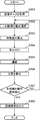
- FIG. 7 is a flowchart showing an example of the generation process of the list information 205 in the behavior recognition device 1 according to the embodiment. Details of the list information 205 will be described later.
- the flowchart of FIG. 7 is executed, for example, when the action recognition device 1 is installed in the house. Further, the flowchart of FIG. 7 may be executed when, for example, the floor plan information 202 or the position information 203 is changed.
- the first acquisition unit 101 acquires the action selection table T1 (target action information 201) and stores it in the memory 200 (step S101).
- the first acquisition unit 101 acquires the floor plan information 202 and stores it in the memory 200 (step S102).
- the second acquisition unit 103 acquires the position information 203 of the image sensor 2 and stores it in the memory 200 (step S103).
- the second acquisition unit 103 may acquire the position information 203 of each image sensor 2.
- the action selection unit 102 identifies the space in which the image sensor 2 is installed by using the position information 203 and the floor plan information 202 (step S104). For example, the action selection unit 102 may specify the space by examining in which space the coordinate data indicated by the position information 203 is located among the plurality of spaces included in the floor plan information 202. Further, when the position information 203 for the plurality of image sensors 2 is acquired, the action selection unit 102 may specify the space corresponding to each position information 203.
- the action selection unit 102 refers to the action selection table T1 and selects a candidate action that is a target action corresponding to the specified space (step S105).
- a candidate action that is a target action corresponding to the specified space.
- the recognizer 111 corresponding to each candidate action is selected.
- the recognizer selection unit 110 selects the recognizer 111 corresponding to the selected candidate action (step S106). Details of this process will be described later with reference to FIG.
- the recognizer selection unit 110 corresponds to the identifier of each image sensor 2, the candidate action recognized from the image data 204 captured by each image sensor 2, and the recognizer 111 used for recognizing the candidate action.
- the attached list information 205 is generated and stored in the memory 200 (step S107). As a result, the list information 205 is generated.
- FIG. 8 is a flowchart showing the details of the process of step S106 of FIG.
- the recognizer selection unit 110 acquires the label of the target action acquired in step S101 (step S201).
- the recognizer selection unit 110 refers to the recognizer selection table T2 and selects the recognizer 111 used for recognizing the target action (step S202).
- the recognizer 111 used for recognition is selected for each target action.
- the recognizer selection unit 110 selects the dependent recognizer 111 (step S203).
- which recognizer 111 depends on which recognizer 111 is determined by referring to the item of the dependency relationship of the recognizer in the prior knowledge table T4 described later.
- FIG. 9 is a flowchart showing an example of the action recognition process in the action recognition device 1.
- FIG. 9 shows processing when one frame of image data 204 is captured by one image sensor 2. Therefore, when there are a plurality of image sensors 2, the process of FIG. 9 is executed in parallel with respect to the image data 204 captured by each image sensor 2. Further, the process of FIG. 9 may be executed each time one frame of image data 204 is captured, or may be executed each time a plurality of frames of image data 204 are captured.
- the second acquisition unit 103 acquires the image data 204 captured by the image sensor 2 and stores it in the memory 200 (step S301).
- the recognizer selection unit 110 refers to the list information 205 and selects one candidate action among the candidate actions associated with the identifier of the image sensor 2 that captured the image data 204 (step S302). As a result, the candidate action corresponding to the space is selected.
- the recognizer selection unit 110 refers to the list information 205, inputs the image data 204 to the recognizer 111 used for recognizing the candidate action of 1, and causes the recognizer 111 to calculate the feature amount (step S303). ).
- the calculated feature amount is input to the coupler 121.
- the coupler 121 weights the feature amount input by the weighting coefficient corresponding to the candidate action of 1 (step S304).
- the coupler 121 concatenates the weighted features (step S305).
- the concatenated features are input to the classifier 122.
- the classifier 122 calculates the likelihood of the input feature amount (step S306).
- the recognizer selection unit 110 determines whether or not all candidate actions have been selected (step S307). If all candidate actions have not been selected (NO in step S307), the process returns to step S302, and the likelihood for the next selected candidate action is calculated.
- the output unit 106 uses the label of the candidate action having the highest likelihood among the likelihoods calculated for each candidate action as the recognition result. Output (step S308).
- step S308 not only the label of the candidate action having the maximum likelihood but also the label of k candidate actions may be output in descending order of the likelihood. For example, if k is 5, the output will be in the upper 5 classes.
- the candidate behavior to be recognized is selected from the target behaviors based on the position information 203 and the floor plan information 202 of the image sensor 2, and the recognition result for the candidate behaviors is calculated. ing. Therefore, it is possible to accurately recognize the behavior of a person who depends on space.
- the first approach is a behavior recognition method that extracts behavioral features from input data using a plurality of convolutional layers and pooling layers, which are general-purpose feature extraction layers.
- this behavior recognition method the likelihood of a given behavior is calculated from the extracted features.
- this behavior recognition method is not a good approach in terms of both computational cost and recognition accuracy.
- the second approach is a behavior recognition method in which features that contribute to the behavior to be recognized are heuristically designed, and the likelihood of a given behavior is calculated from the extracted features, similar to the first approach. .. A detailed description of this heuristic design will be given below.
- skeletal information expression that connects joints such as shoulders and knees with a straight line
- an extrinsic rectangle bounding box
- a heuristic behavior recognition method using the above-mentioned skeletal information or circumscribing rectangle has been proposed.
- neither the skeletal information nor the circumscribing rectangle was devised as a feature of behavior recognition. Therefore, the behavior recognition method is determined based on the result of heuristic trial and error.
- the conditions to be tried are limited because a large amount of time is required for learning and evaluating DNN.
- the behavior to be recognized is the same as or similar to the conventional recognition target, and the feature amount used in the conventional recognition can be referred to.
- the behavior to be recognized is the class defined by the dataset.
- the conventional behavior recognition method by DNN is not an effective approach even when the behavior to be recognized is not included in the conventional recognition target. Therefore, it is necessary to extract features according to the behavior to be recognized in efficient behavior recognition. For that purpose, it is necessary to have a configuration that can determine the extraction method of the feature amount when the learning data of the behavior to be recognized is given.
- Behavior recognition by DNN calculates the likelihood of a given behavior by processing the sensor data with DNN. To get the label for a single action, select the label for the action with the highest likelihood.
- calculating the likelihood of each action from a plurality of DNNs or feature extractors there is no guarantee that the larger the amount of feature data, the higher the recognition accuracy. This is because there is a high possibility that the feature amount contains a component that behaves like noise without contributing to the recognition accuracy.
- increasing the number of DNNs or feature extractors used does not necessarily improve accuracy. That is, it is important to set the number of DNNs or feature extractors to the number at which information suitable for the action to be recognized can be obtained.
- the configuration of the DNN or feature extractor to be used is important.
- the convolution layer obtains output by applying a given kernel to the input image data.
- convolutional layers There are two types of convolutional layers: two-dimensional convolution that is applied to one-frame two-dimensional image data, and three-dimensional convolution that is applied to N-frame (N is the number of frames) two-dimensional image data.
- the number of parameters Wc of the weighting coefficient of convolution is k for the kernel size, d for the convolution dimension (2 for 2D convolution, 3 for 3D convolution), Ci for the input channel, and the number of output channels. If it is Co, it can be expressed by the equation (3).
- the multiplication number Uc required for the convolution calculation can be expressed by the equation (4), where s is the stride number which is the movement amount of the kernel. For the sake of simplicity, the vertical and horizontal processing of the image is the same.
- the number Wfc of the weighting coefficient of the fully connected layer is the product of the number of input channels Ci and the number of output channels Co as shown in the equation (5).
- the multiplication number Ufc required for the calculation of the fully connected layer is equal to the number of weighting coefficients Wfc as shown in the equation (6).
- the number of weighting coefficients Wfc corresponds to the number of memories required for execution
- the multiplication number corresponds to the number of operations required for execution.
- the number of convolution operations is larger than the full combination due to the multiplication caused by the kernel.
- both the number of weighting coefficients and the multiplication number increase. Therefore, the calculation cost of the DNN centering on the convolutional layer composed of multiple layers as shown in FIG. 2 becomes large, and even when the graphics process unit (GPU) is used for the desktop computer, it can be regarded as real-time processing at 24 fps (24 fps). It may be difficult to process (equivalent to a general movie). When a plurality of DNNs are used to improve the recognition accuracy, real-time processing becomes more difficult.
- the reason why the calculation cost of the conventional DNN is high is that the layers constituting the network are mainly arranged in series, and most of the layers are convolutional layers. Even in the middle layer of the network, the number of weighting coefficients is large and the multiplication number is also increasing.
- the output of the middle layer is a tensor that is difficult for humans to interpret, and the output of the middle layer is not always the optimum expression for recognition. In other words, there are more weighting factors in the middle layer than necessary, and the number of multiplications is increasing. That is, by effectively expressing the human behavior or the state of space in the middle layer with a small number of parameters, it is possible to reduce the number of weighting coefficients and the multiplication number.
- the number of data (number of bytes) required to represent the input image data is the product of the vertical length, the horizontal length, and the number of channels of the image data.
- 34 is the product of the number of vertices of the skeleton (for example, 17 points) and the number of components of the coordinate data (x, y) of the vertices of the skeleton.
- Behaviors of the person to be recognized include, for example, walking, running, standing, talking, cleaning, starting cooking, as well as, for example, sleeping, lying down, sitting, watching TV. It also includes stationary behavior such as being.
- the number of recognizers 111 used in the first action recognition unit 104 is at least one.
- the combination of the recognizers 111 is in the factorial order of N.
- the factorial order of N diverges faster than the exponential function. Considering the learning time, when N becomes larger than about 5, it becomes difficult to learn all the combinations of the recognizers 111.
- the problem related to the combination of the recognizers 111 is expressed as a mathematical problem.
- recognition accuracy and calculation cost can be obtained.
- the recognition accuracy to be satisfied for example, 70%
- finding a combination that minimizes the calculation cost while satisfying the recognition accuracy becomes a conditional combinatorial optimization problem.
- Such a combinatorial optimization problem cannot be solved analytically when the number of combinations becomes a number that is difficult to perform a full search. Therefore, a semi-optimal solution will be searched.
- the recognizer 111 is selected based on prior knowledge and the greedy method.
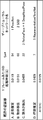
- FIG. 10 is a diagram showing a data structure of the prior knowledge table T4 that summarizes information about the recognizer 111.
- This table is stored in the memory 200.
- the prior knowledge table T4 has items related to the identification number of the recognizer 111, the recognition content, the input sensor data, the relative calculation cost, and the dependency of the recognizer. Each item will be described.
- As the identification number a unique number (for example, a serial number) is given to the registered recognizer 111, and the identification number becomes an index or a hash in the combination search.
- the recognition content is the content recognized by the recognizer 111.
- the input sensor data is sensor data required for the recognizer 111 to make an inference, and is zero or more.
- the reason why 0 is included is that the recognizer 111 inferred only by the feature amount calculated by the other recognizer 111 depending on the recognition device 111 does not need the sensor data.
- the relative calculation cost is a relative value of the calculation cost of the recognizer 111.
- the relative calculation cost is a relative value calculated based on the benchmark result executed by the reference computer.
- the relative calculation cost may be calculated based on the benchmark results of a plurality of computers, or the absolute value which is the benchmark result itself may be adopted.
- the dependency of the recognizer is information indicating whether or not it depends on another recognizer 111.
- the recognizer 111 having an identification number of 4 to 6 depends on the recognizer 111 having an identification number of 3. This is because the results of face detection are used when performing head orientation estimation, age / gender estimation, and individual estimation.
- a recognizer 111 that detects a specific area of a person may be used, such as the recognizer 111 that detects a hand or a foot. Further, a recognizer 111 that outputs dense data such as a mask indicating the range of an image may be used.
- the greedy algorithm is a method of making the best choice based on partial information.
- the recognition accuracy when only one recognizer 111 is selected is calculated using the learning data.
- the recognition accuracy is high when only one recognizer 111 is used, it is expected that the recognition accuracy when the recognizer 111 is used in combination with another recognizer 111 is also high.
- the greedy method when the recognition accuracy is high when only one recognizer 111 is used, it is assumed that the recognition accuracy when the recognizer 111 is used in combination with another recognizer 111 is also high, and the evaluation target is obtained.
- the priority of the combination of the recognizers 111 is determined. Specifically, the recognizer 111 is sorted in descending order of recognition accuracy when only one recognizer 111 is used, and the first recognizer 111 is evaluated preferentially. For example, when the head is the first recognizer 111 and the indexes are assigned in order, the index close to the head is preferentially used, such as 1, 2, 1, 3, 1 to 3, 1 to 4.
- a more detailed index selection method can be expressed by a parameter X that considers the Xth index from the beginning and a parameter Y that allows selection of up to Y indexes.
- the recognizer selection table T2 shown in FIG. 5 is created based on, for example, the selection result of the recognizer 111 as described above.
- the selection of the classifier 122 will be described. Since the feature amount output by the first action recognition unit 104 is data obtained by vectorizing a small number of parameters such as skeleton information, it can be identified without using CNN. The classifier 122 has a significantly smaller amount of calculation processing than the CNN. Cross-validation may be performed on a plurality of classifier candidates, and the classifier 122 having the maximum accuracy or F1 score may be selected.
- Candidate classifier 122 is, for example, a classifier using logistics regression, support vector machine (SVM), decision tree, random forest, k-nearest neighbor method, Gaussian naive Bayes, perceptron, or stochastic descent method.
- SVM support vector machine
- the classifier 122 may be trained using the learning data including the label of the target behavior. For example, image data of a moving image as learning data is prepared for each label of "start cooking” and "not start cooking”. Using the prepared image data, the behavior recognition process shown in FIG. 9 is executed by the behavior recognition device 1, the obtained label is compared with the correct label of the learning data, and the classifier is used so that the error is minimized. Update the weight of 122.
- CNN was used as the existing recognizer 111.
- PoseNet is used as the recognition device for posture estimation
- second: SSD is used as the recognition device 111 for object detection
- third: Retina Face is used as the recognition device 111 for face detection.
- 4: DeepPeasedPose was used as the recognizer 111 for head-to-head estimation.
- classifier 122 a stochastic descent classifier was used.
- 5: PresentationFlowNet was used as the existing behavior estimation AI.
- one color image data including three people was used as the input image data.
- This image data had a resolution of 640 ⁇ 480, a number of channels of 3, and a resolution of 8 bits.
- the calculation cost of the classifier 122 was ignored because it was sufficiently smaller than the existing recognizer 111 regardless of the number of classes to be identified.
- a desktop personal computer including a calculation aid by a graphics process unit (product model number: Geforce GTX 1080Ti) was used.
- FIG. 11 is a table summarizing the processing time per frame when the existing recognizers 111 are individually executed.
- the processing time when each of the recognizers 111 of processing A (posture estimation), processing B (object detection), and processing C (head orientation detection) of FIG. 11 was executed was measured.
- the processing time of processing C includes the processing time of head orientation estimation and face detection. Since the processes A, B, and C are independent processes, they can be executed in parallel. When the overhead was ignored, the maximum value of the processing time among the processing A, B, and C was 0.0455 seconds of the processing C. On the other hand, when the processes A, B, and C were sequentially processed, the total processing time was 0.0725 seconds.
- the processing time of processing D (existing behavior estimation AI) was 0.1429 seconds. Therefore, when the processes A, B, and C were processed in parallel, the processing speed was three times that of the process D. When the processes A, B, and C were sequentially processed, the processing speed was twice that of the process D. As described above, it was confirmed that the processing speed of using the plurality of recognizers 111 is significantly faster than that of the existing behavior estimation AI.
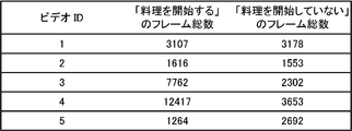
- FIG. 12 is a table summarizing the input image data.
- the video ID is an identifier for identifying five moving images.
- the total number of the “start cooking” frame and the “not start cooking” frame is shown for each moving image.
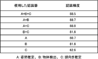
- FIG. 13 is a table summarizing the results of a simulation performed to evaluate the recognition accuracy of the behavior recognition device 1.
- the process A + B + C shows a case where the first action recognition unit 104 is composed of the recognizer 111 of the process A, the recognizer 111 of the process B, and the recognizer 111 of the process C.
- the process A + B is the first.
- the case where the action recognition unit 104 is composed of the recognizer 111 of the process A and the recognizer 111 of the process B is shown.
- the recognition accuracy and processing time of each of the eight types of classifiers 122 were measured for each of the combinations of processes A to C shown in FIG.
- the eight classifiers 122 are logistic regression, support vector machine, decision tree, random forest, k-nearest neighbor method, Gaussian naive bays, perceptron, and stochastic descent method. In this simulation, among the eight types of classifier 122, the processing time and the recognition accuracy were the shortest when the stochastic descent classifier 122 was adopted.
- the average value of the recognition accuracy was 88.5% among the combinations of the processes A to C shown in FIG. This result is higher than the expected value of the recognition accuracy of 50% when the recognition accuracy of the behavior recognition device 1 randomly estimates the two-class classification of "start cooking” and "not start cooking”. Show that. Therefore, from this simulation result, it was confirmed that the behavior recognition device 1 can recognize the behavior.
- the best recognition accuracy was 88.8% in processing A + C.
- the recognition accuracy of 88.7% was obtained only by the process A.
- the threshold value of recognition accuracy is 88.7%
- the calculation cost is minimized when only the process A is used.
- the processing A + B + C is not the best because there is a recognizer 111 that does not contribute to the improvement of accuracy, and the recognizer 111 behaves like a noise source.
- each recognizer 111 constituting the first action recognition unit 104 is not limited to the above-mentioned one, and the optimum recognizer 111 is appropriately adopted according to the target action.
- the classifier 122 a classifier 122 other than the stochastic descent method may be adopted.
- the behavior recognition device 1 is configured by itself, but the present disclosure is not limited to this, and may be configured by a plurality of devices.
- FIG. 14 is a block diagram showing an example of the configuration of the behavior recognition device 1A according to the modified example of the present disclosure.
- the action recognition device 1A is composed of a server.
- the action recognition device 1A further includes a communication unit 500.
- the communication unit 500 transmits the recognition result output by the output unit 106 to the home electric appliance 600 via the network NT and the gateway 700.
- the communication unit 500 receives the image data taken by the image sensor 300 installed in the house.
- the network NT is a wide area communication network such as the Internet.
- the gateway 700 is installed in the house and connects the image sensor 300 and the home electric appliance 600 to the network NT.
- the home appliance 600 is a washing machine, a microwave oven, a television, and the like.
- the home electric appliance 600 executes control using the action recognition result transmitted from the action recognition device 1A, and displays the recognition result.
- the behavior recognition device 1A can recognize the behavior of a person in the house even when the server is configured.
- image data is used as input data, but in addition to this, thermal image data, depth image data, audio data, room temperature data, humidity data, illuminance data, and wireless radio wave data. At least one of them may be used.
- an action having a frequency of occurrence of 0 can be excluded from the recognition target.
- a sofa with a low movement frequency is reflected in the camera, it is assumed that the behavior of sitting there is high.
- a movable chair exists in the space, it is assumed that the behavior of sitting on the chair is high. This makes it possible to determine the value of the weighting coefficient of the weighting table T3 shown in FIG.
- Equipment that cannot be moved in the house (second object described later) represented by water supply equipment is also important in behavior recognition.
- Water-using activities such as cooking or washing usually use equipment installed in the home. Therefore, the position of the equipment around the water and the positional relationship of the person are the factors for judging the behavior recognition. This is based on the high frequency of behaviors that require water in human life.
- Dwellings are generally divided into 4 to 10 rooms by doors or fixed or movable walls.
- the multi-story dwelling is equipped with elevating equipment such as stairs.
- the dwelling has an object (a third object described later) including a plurality of spaces and a large number of doors.
- the names of these spaces, the positions of doors or elevating equipment, and the positional relationship with people are the factors for determining behavior recognition. This is based on the fact that there are actions that are performed only in a specific room, such as cooking or bathing.
- FIG. 15 is a block diagram showing an example of the configuration of the behavior recognition device 1B according to the modified example (3) of the present disclosure.
- the floor plan feature amount is extracted based on the floor plan information 202, and the action selection table T1 is generated based on the extracted floor plan feature amount.
- the floor plan information 202 includes not only the information of the space in the building but also the information (type information and position information) of the objects (equipment and equipment) installed in each space.
- the action recognition device 1B is communicably connected to the display terminal 400 via a predetermined communication path.
- a predetermined communication path a wireless LAN and Bluetooth (registered trademark) can be adopted. Further, the predetermined communication path may be the Internet.
- the display terminal 400 is composed of, for example, a smartphone or a tablet computer.
- the display terminal 400 is possessed by, for example, a user.
- the user is, for example, the installer of the image sensor 2.
- the builder is, for example, a resident of a residence or a contractor.
- the processor 100B of the action recognition device 1B further includes an installation support unit 301 and a floor plan feature amount extraction unit 302 with respect to FIG.
- the flooring feature amount extraction unit 302 extracts an object installed in the building based on the flooring information 202, and uses the extracted object as a movable first object, a second object that is a water supply facility, and a building structure. It is classified into any of the third objects, and for each of the classified objects, the flooring feature amount in which the installation position and the classification information indicating the classification result are associated with each other is extracted.
- the floor plan feature quantity is composed of, for example, a two-dimensional table.
- the first object includes a movable object such as furniture and electric appliances.
- the first object is a vacuum cleaner, a coffee maker, a laptop computer, a chair, a sofa, and the like.
- the second object is, for example, a non-movable water supply facility such as a sink and a washbasin.
- the third object is the structure of the building such as the entrance, kitchen, living room, dining room, bedroom, bathroom, elevating equipment, and washroom.
- the installation position is composed of, for example, two-dimensional or three-dimensional coordinate data based on the entrance of the building.
- the installation position of the third object may be composed of coordinate data indicating a region where the third object is located. This makes it possible to determine in which space the first object and the second object are installed in the building.
- the installation position of the first object and the second object may include the name of the space of the building in which the first object and the second object are located, in addition to the coordinate data in which the first object and the second object are located. good.
- the classification information is information indicating which of the first object to the third object the object extracted from the floor plan information 202 corresponds to.
- the floor plan feature amount extraction unit 302 generates the action selection table T1 based on the extracted floor plan feature amount.
- the installation position of the first object indicates the position where the user operates.
- the installation position of the coffee maker can be associated with the behavior of brewing coffee.
- the installation position of the microwave oven can be associated with the behavior of the user to start cooking.
- the installation position of the second object indicates the position where the operation using water is performed.
- the location of the sink can be associated with the behavior of washing dishes.
- the installation position of the third object indicates the name of the space, the user's entry and exit into the space, and the range in which the user can move.
- the installation position of the bathroom door can be associated with the bathing operation.
- the floor plan feature amount extraction unit 302 generates an action selection table based on the extracted floor plan feature amount.
- the action selection table T1 is a table in which one or more spaces in a building and a target action that is likely to be performed by a user in each space are associated with each other.
- the floor plan feature amount extraction unit 302 determines what kind of equipment or equipment is installed in each space from the floor plan feature amount, and refers to a predetermined rule from the determination result and the classification information. Then, the action selection table T1 may be generated.
- the rules are, for example, heating a dish in a microwave oven, which is the first object, brewing coffee in a coffee maker, which is the first object, and washing dishes in a sink, which is the second object.
- a rule can be adopted in which the equipment and the target action that is likely to be performed by the equipment or the equipment are associated with each other.
- the floor plan feature amount extraction unit 302 may generate an action selection table T1 to which the target actions such as starting cooking, brewing coffee, and washing dishes are associated with the kitchen.
- the floor plan feature amount extraction unit 302 may associate the target behavior with other spaces in the building in the same manner.
- the rule may include not only the device or equipment but also the target action that is likely to be performed on the space itself. For example, as described in FIG. 4, rules such as starting cooking for the kitchen, washing for the washroom, living room, dining room, reading for the bedroom, and eating for the living room and dining room can be adopted. ..
- the floor plan feature amount extraction unit 302 may set the weighting coefficient shown in the weight table T3 shown in FIG. 6 from the extracted floor plan feature amount. For example, if the kitchen is equipped with a sink, refrigerator, microwave oven, and gas stove, the weight factor We for the kitchen is set to 1 for the sink, refrigerator, microwave oven, and gas stove, and 0 for other equipment. do it.
- the floor plan feature amount extraction unit 302 may set the weighting coefficient We for spaces other than the kitchen as in the kitchen.
- the first acquisition unit 101 may acquire the action selection table T1 generated in this way as the target action information.
- the installation support unit 301 acquires the name of the space of the building in which the image sensor 2 is installed via the display terminal 400, and makes an image so that the specific device or the specific equipment related to the space is included in the field of view of the image sensor 2.
- An installation support unit that outputs an installation guidance for installing the sensor 2 to the display terminal 400 is further provided.
- FIG. 16 is a diagram showing a scene in which the image sensor 2 is installed at the entrance 501.
- FIG. 17 is a diagram showing an example of interaction between the user and the display terminal 400 in a scene where the image sensor 2 is installed at the entrance 501.
- step ST1 the display terminal 400 accepts the operation of opening the setting screen from the user, and displays a list of the spaces in which the image sensor 2 is scheduled to be installed.
- the names of the spaces in which the image sensor 2 is installed are listed, such as A: entrance, B: kitchen, C: living room, and so on.
- step ST2 the display terminal 400 accepts an operation of a user who selects the name of the space in which the image sensor 2 is installed from the names of the spaces displayed in the list.
- the display terminal 400 transmits the name of the selected space to the action recognition device 1B.
- "A: entrance” is selected.
- step ST3 the display terminal 400 displays a message prompting the user to install the image sensor 2, such as "Please install at a position where the door is reflected. After installation, press OK.” Along with this message, an OK button for notifying the display terminal 400 that the user has completed the installation work of the image sensor 2 is displayed on the setting screen.
- the image sensor 2 is installed at the entrance 501.
- step ST4 the display terminal 400 accepts the operation of the user who presses the OK button.
- the display terminal 400 that has received the operation of pressing the OK button transmits information indicating that the OK button has been pressed to the action recognition device 1B.
- the installation support unit 301 that has acquired the information indicating that the OK button has been pressed acquires the image data taken by the image sensor 2 and executes a process of detecting the door 401 from the acquired image data. At this time, the installation support unit 301 causes the display terminal 400 to display the message "The door is automatically detected" (step ST5).
- the installation support unit 301 may detect the door 401 using a predetermined recognizer.
- the door 401 is an example of the specific equipment at the entrance 501.
- the specific equipment is predetermined according to the space in which the image sensor 2 is installed.
- As the predetermined recognizer for example, a recognizer prepared in advance for detecting the door 401 is adopted.
- FIG. 18 is a diagram showing an interaction following FIG.
- the display terminal 400 acquires annotation information indicating the detection result of the door 401 from the installation support unit 301, and superimposes and displays the annotation image indicated by the acquired annotation information on the image captured by the image sensor 2. Is displayed. On this setting screen, a message prompting the correction of the annotation image is displayed, such as "Adjust to match the door at the position of the automatically detected red door guide and press OK".
- the annotation information is, for example, coordinate data of an annotation image.
- FIG. 19 is a diagram showing an example of setting screens G1 and G2 on which the annotation image A1 is superimposed.
- the setting screen G1 shows the annotation image A1 before the modification, and the setting screen G2 displays the annotation image A1 after the modification.
- the annotation image A1 is composed of a rectangular bounding box.
- the annotation image A1 has a predetermined color (here, red).
- an OK button 1901 notifying the completion of the correction work of the annotation image A1 is displayed.
- the circle mark P1 is displayed at the upper left vertex of the annotation image A1, and the circle mark P2 is displayed at the lower right vertex of the annotation image A1.
- the display terminal 400 When the display terminal 400 receives an operation for moving the circle marks P1 and P2, the display terminal 400 changes the size of the annotation image A1 in conjunction with the accepted operation.
- the annotation image A1 which is the detection result of the door 401 by the recognizer is displayed.
- This annotation image A1 is displaced diagonally upward to the left of the door 401, indicating that the door 401 cannot be recognized correctly.
- the user inputs an operation to move the circle marks P1 and P2 so that the shape of the annotation image A1 becomes the extrinsic rectangle of the door 401.
- the setting screen G2 is obtained.
- the annotation image A1 is positioned on the circumscribed rectangle of the door 401.
- the annotation image A1 displayed at a position deviated from the door 401 on the setting screen G1 is modified so as to surround the entire area of the door 401 as shown in the setting screen G2.
- the recognizer can obtain the correct position of the door 401 on the image.
- step ST7 the display terminal 400 accepts an operation of pressing the OK button 1901 from the user who has completed the adjustment of the annotation image A1.
- the display terminal 400 that has received this operation transmits the coordinate data of the modified annotation image A1 to the installation support unit 301.
- the installation support unit 301 Upon receiving this coordinate data, stores the modified coordinate data of the annotation image A1 in the memory 200 in association with the position information 203 of the image sensor 2 installed at the entrance 501.
- the recognizer 111 for recognizing the target behavior corresponding to the entrance 501 refers to the image data taken by the image sensor 2 installed in the entrance 501 with reference to the annotation image A1 indicated by the coordinate data. Recognize the behavior of. As a result, the recognizer 111 can efficiently recognize the user's behavior.
- step ST8 the display terminal 400 receives the information indicating that the coordinate data has been saved from the installation support unit 301, and therefore displays the message "The settings have been saved.”
- step ST9 the display terminal 400 accepts an operation of closing the setting screen from the user. As a result, the display terminal 400 closes the setting screen.
- FIG. 20 is a diagram showing a scene in which the image sensor 2 is installed in the kitchen 502.
- FIG. 21 is a diagram showing an example of interaction between the user and the display terminal 400 in a scene where the image sensor 2 is installed in the kitchen 502.
- Step ST1 is the same as step ST1 in FIG.
- the display terminal 400 accepts an operation of selecting "B: kitchen” as the installation location of the image sensor 2 from the user.
- Step ST3 is the same as step ST3 in FIG.
- the display terminal 400 accepts the operation of the user who presses the OK button.
- the display terminal 400 that has received the operation of pressing the OK button transmits information indicating that the OK button has been pressed to the action recognition device 1B.
- the installation support unit 301 that has acquired the information indicating that the OK button has been pressed acquires the image data taken by the image sensor 2 and executes a process of detecting the refrigerator 402 from the acquired image data. As a result, the installation support unit 301 causes the display terminal 400 to display the message "The refrigerator is automatically detected" (step ST5).
- the installation support unit 301 may detect the refrigerator 402 using a predetermined recognizer.
- the refrigerator 402 is an example of a specific device in the kitchen 502. The specific device is predetermined according to the space in which the image sensor 2 is installed. As the predetermined recognizer, for example, a recognizer prepared in advance for detecting the refrigerator 402 is adopted.
- FIG. 22 is a diagram showing an interaction following FIG. 21. Steps ST6 to ST9 are the same as those in FIG.
- FIG. 23 is a diagram showing an example of the setting screens G3 and G4 on which the annotation image A1 is superimposed.
- the setting screen G3 displays the annotation image A1 before modification, and the setting screen G3 displays the annotation image A1 after modification.
- the annotation image A1 which is the detection result of the refrigerator 402 by the recognizer is displayed.
- This annotation image A1 is displaced upward from the refrigerator 402, and it can be seen that the refrigerator 402 cannot be recognized correctly.
- the user inputs an operation of moving the circle marks P1 and P2 so that the shape of the annotation image A1 becomes the circumscribing rectangle of the refrigerator 402.
- the setting screen G4 is obtained.
- the annotation image A1 is positioned in the circumscribed rectangle of the refrigerator 402.
- the annotation image A1 displayed at a position deviated from the refrigerator 402 on the setting screen G3 is modified so as to surround the entire area of the refrigerator 402 as shown on the setting screen G4.
- the recognizer cannot accurately recognize the position on the image of the refrigerator 402
- the correct position on the image of the refrigerator 402 can be obtained.
- the recognizer 111 for recognizing the target behavior corresponding to the refrigerator 402 refers to the image data taken by the image sensor 2 installed in the refrigerator 402 with reference to the annotation image A1 indicated by the coordinate data. Recognize the behavior of. As a result, the recognizer 111 can efficiently recognize the user's behavior.
- FIG. 24 is a diagram showing an example of the interaction between the user and the display terminal 400 when modifying the annotation image A1 after installing the image sensor 2.
- the angle of the image sensor 2 may fluctuate due to some external force applied after installation.
- the coordinate data indicated by the annotation image A1 set at the time of installation deviates from the position on the image of the specific device or the specific equipment. The following correction work is performed to correct this deviation.
- step ST1 the display terminal 400 accepts the operation of opening the setting screen from the user, and displays a message prompting to confirm the misalignment of the image sensor 2.
- the message "Check if the camera position is correct.
- the red guide is the current setting.
- the position automatically detected by the light blue guide” is displayed.
- FIG. 25 is a diagram showing an example of setting screens G5 and G6 on which the annotation image A1 is superimposed and displayed.
- the setting screen G5 shows the annotation image A1 before the modification
- the setting screen G6 shows the annotation image A1 after the modification.
- the annotation image A1 corresponds to a red guide.
- the dotted line annotation image A2 shows the annotation image which is the detection result of the refrigerator 402 by the recognizer.
- the annotation image A2 corresponds to a light blue guide.
- the annotation image A1 is displayed shifted upward with respect to the annotation image A2.
- step ST2 the user confirms the deviation of the angle of the image sensor 2 from the setting screen G5, and adjusts the angle of the image sensor 2.
- the display terminal 400 determines by image processing whether or not the position of the annotation image A1 matches the position of the annotation image A2. When the display terminal 400 determines that they match, the display terminal 400 displays a message indicating that the angle of the image sensor 2 has returned to the angle at the time of installation.
- step ST4 the display terminal 400 accepts an operation of closing the setting screen from the user. As a result, the display terminal 400 closes the setting screen.
- the recognizer 111 can accurately recognize the user's behavior.
- the behavior recognition device of the present invention is useful when recognizing a person's behavior in a building.
Landscapes
- Engineering & Computer Science (AREA)
- Theoretical Computer Science (AREA)
- Physics & Mathematics (AREA)
- General Physics & Mathematics (AREA)
- Multimedia (AREA)
- Computer Vision & Pattern Recognition (AREA)
- General Health & Medical Sciences (AREA)
- Health & Medical Sciences (AREA)
- Evolutionary Computation (AREA)
- Human Computer Interaction (AREA)
- Artificial Intelligence (AREA)
- Medical Informatics (AREA)
- Psychiatry (AREA)
- Computing Systems (AREA)
- Databases & Information Systems (AREA)
- Social Psychology (AREA)
- Software Systems (AREA)
- Computational Linguistics (AREA)
- Life Sciences & Earth Sciences (AREA)
- Biodiversity & Conservation Biology (AREA)
- Biomedical Technology (AREA)
- Molecular Biology (AREA)
- Oral & Maxillofacial Surgery (AREA)
- Image Analysis (AREA)
Abstract
行動認識装置は、画像センサの位置情報と間取り情報とに基づいて対象行動の中から認識候補となる候補行動を選択し、画像センサが検出した画像データを取得し、候補行動に応じた1以上の認識器を決定し、1以上の認識器を用いて画像データの特徴量を算出し、特徴量に基づいて候補行動を認識する。
Description
本開示は建物におけるユーザの行動を認識する技術に関するものである。
近年、動画像から人の行動を認識する研究が進められている。例えば、特許文献1には、動画像から人を含む人領域を検出し、前記領域に映る人の姿勢と周辺の物体との組み合わせから人の行動を認識する技術が開示されている。
例えば、特許文献2には、動画像から人の関節に基づくスケルトン情報を時系列で抽出し、スケルトン情報の囲み領域を抽出し、抽出した囲み領域から人の行動を認識する技術が開示されている。
しかしながら、特許文献1及び特許文献2の技術によれば、建物の間取り情報が考慮されていないため、建物内の空間に依存する人の行動を精度よく認識するためには改善の必要があった。
本開示の一態様に係る行動認識装置は、建物における人の行動を認識する行動認識装置であって、予め定められた認識対象となる1以上の対象行動を含む対象行動情報と、前記建物の間取り情報と、前記建物に設置された画像センサの位置情報とを取得する第1取得部と、前記画像センサの位置情報と前記間取り情報とに基づいて前記対象行動情報に含まれる前記1以上の対象行動の中から認識候補となる候補行動を選択する行動選択部と、前記画像センサが検出した画像データを取得する第2取得部と、前記候補行動に応じた1以上の認識器を決定し、前記1以上の認識器を用いて前記画像データの特徴量を算出する第1行動認識部と、前記特徴量に基づいて前記候補行動を認識する第2行動認識部と、前記第2行動認識部による認識結果を出力する出力部とを備える。
本開示によれば、建物内の空間に依存する人の行動を精度よく認識することができる。
(本開示に至る知見)
従来、センサデータである動画像または静止画像から人の行動を推定する方法が提案されている。このような方法においては、認識すべき対象の行動に対して予めラベルが付与され、センサデータがどのラベルに該当するかを判定することが行われる。センサデータが動画像または静止画像である場合、畳み込み層及びプーリング層を用いたディープニューラルネットワーク(DNN)を使用することで高い認識精度が実現可能である。しかしながら、現状のDNNを使用した方法では、認識対象とする行動が人の歩行のような動作する空間に依存しない行動が認識対象とされている。そのため、空間に依存する行動を認識対象とするためには空間に関する情報を考慮に入れてDNNを一から学習させることが要求され、手間及びコストがかかる。
従来、センサデータである動画像または静止画像から人の行動を推定する方法が提案されている。このような方法においては、認識すべき対象の行動に対して予めラベルが付与され、センサデータがどのラベルに該当するかを判定することが行われる。センサデータが動画像または静止画像である場合、畳み込み層及びプーリング層を用いたディープニューラルネットワーク(DNN)を使用することで高い認識精度が実現可能である。しかしながら、現状のDNNを使用した方法では、認識対象とする行動が人の歩行のような動作する空間に依存しない行動が認識対象とされている。そのため、空間に依存する行動を認識対象とするためには空間に関する情報を考慮に入れてDNNを一から学習させることが要求され、手間及びコストがかかる。
上述の特許文献1では、人の姿勢と人の周辺の物体との組み合わせを考慮して人の行動が認識されているが、人の周囲に、人の行動とは無関係な物体が映り込んでいる場合、その物体は人の行動を推定するに際して有用な情報にはならない。そのため、特許文献1では、空間に依存する人の行動を認識するにはさらなる改善が必要である。
上述の特許文献2では、スケルトン情報の囲み領域から人の行動が推定されていることからも明らかなように、認識対象の行動として背景に依存しない行動が想定されている。そのため、特許文献2では、例えばキッチンで行う調理行動のように、空間に強く依存する行動を推定するにはさらなる改善が必要である。
そこで、本発明者は、建物の間取り情報を考慮すれば、建物内の空間に依存する人の行動を精度よく認識できるとの知見を得て、以下に示す本開示の各態様を想到するに至った。
本開示の一態様に係る行動認識装置は、建物における人の行動を認識する行動認識装置であって、予め定められた認識対象となる1以上の対象行動を含む対象行動情報と、前記建物の間取り情報と、前記建物に設置された画像センサの位置情報とを取得する第1取得部と、前記画像センサの位置情報と前記間取り情報とに基づいて前記対象行動情報に含まれる前記1以上の対象行動の中から認識候補となる候補行動を選択する行動選択部と、前記画像センサが検出した画像データを取得する第2取得部と、前記候補行動に応じた1以上の認識器を決定し、前記1以上の認識器を用いて前記画像データの特徴量を算出する第1行動認識部と、前記特徴量に基づいて前記候補行動を認識する第2行動認識部と、前記第2行動認識部による認識結果を出力する出力部とを備える。
本構成によれば、画像センサの位置情報と建物の間取り情報とに基づいて対象行動の中から認識対象となる候補行動が選択され、候補行動に対する認識結果が算出されている。そのため、建物内の空間に依存する人の行動を精度よく認識することが可能となる。
さらに、本構成によれば、第1行動認識部が候補行動に応じた認識器を決定し、決定した認識器を用いて画像データの特徴量を算出し、算出された特徴量から第2行動認識器が候補行動を認識している。そのため、認識器として既存の認識器を利用することが可能となり、行動認識装置の構築が容易になる。さらに、候補行動に応じた1以上の認識器を用いて特徴量が算出されているため、候補行動の認識に適した特徴量を算出することが可能となり、対象行動の認識精度を高めることが可能となる。
上記行動認識装置において、前記第1行動認識部は、前記候補行動が所定の行動である場合、複数の認識器を決定し、前記第2行動認識部は、前記複数の認識器がそれぞれ算出した特徴量を結合し、結合した特徴量に基づいて前記候補行動を認識してもよい。
本構成によれば、対象行動が所定の行動である場合、複数の認識器が決定されているため、例えば所定の行動が人の周囲にある物体に依存するような場合において、人の特徴量を算出する認識器と、物体の特徴量を算出する認識器とを用いて特徴量を算出することが可能となり、候補行動の認識精度を高めることが可能となる。
さらに、本構成によれば、各認識器が算出した特徴量が結合され、結合された特徴量に基づいて対象行動が認識されている。そのため、複数の認識器により複数の特徴量が算出された場合において、1つの特徴量に結合して第2行動認識部に入力することが可能となり、行動認識装置の構成を簡素化することが可能となる。
上記行動認識装置において、前記所定の行動は、掃除、歯磨き、料理、洗濯、コンピュータの使用、読書、又は食事であってもよい。
本構成によれば、掃除又は歯磨きといった人の行動が人の周囲の物体に依存するような行動の特徴量を画像データから精度よく算出することができる。
上記行動認識装置において、各認識器は、コンボリューションニューラルネットワーク(以下、CNNと呼ぶ。)で構成され、前記第2行動認識部は、ロジスティクス回帰、サポートベクターマシン、決定木、ランダムフォレスト、k近傍法、ガウシアンナイーブベイズ、パーセプトロン、及び確率的降下法のいずれか1つを用いた分類器を用いて前記候補行動を認識してもよい。
本構成によれば、各認識器はCNNで構成され、第2行動認識器はロジスティック回帰等を用いた分類器により構成されているため、第1行動認識部に対して処理コストが低い分類器で第2行動認識器を構成することが可能となる。
上記行動認識装置において、前記第2行動認識部は、前記特徴量を説明変数とし、前記対象行動を目的変数として機械学習された分類器を用いて前記候補行動を認識してもよい。
本構成によれば、各認識器が算出した特徴量を説明変数とし、その特徴量に対応する候補行動を目的変数とする機械学習により生成された分類器を用いて第2行動認識部を構成することができる。例えば、分類器を上述したロジスティック回帰等のCNNに比べて処理負荷が小さい分類器で構成すれば、短時間で分類器を学習させることができる。さらに、第1行動認識部をCNNで構成された既存の認識器で構成することにより、第2行動認識部のみ機械学習させ、第1行動認識部を機械学習させることなく行動認識装置を構成できる。
上記行動認識装置において、前記第2行動認識部は、前記候補行動に応じて予め定められた重み係数を用いて各特徴量に重み付けをし、重み付け後の各特徴量に基づいて前記候補行動を認識してもよい。
本構成によれば、対象行動に応じて各特徴量に重み付けが行われ、重み付けされた各特徴量に基づいて候補行動が認識されるため、候補行動を正確に認識できる。
上記行動認識装置において、前記間取り情報から、前記建物に設置された1以上の物体を抽出し、前記1以上の物体を、移動可能な第1物体、水回り設備である第2物体、及び前記建物の構造物である第3物体のいずれかに分類し、前記1以上の物体のそれぞれについて、分類結果を示す分類情報と設置位置とが対応付けられた間取り特徴量を抽出し、前記間取り特徴量に基づいて、行動選択テーブルを生成し、前記行動選択テーブルは、前記建物の1以上の空間と、各空間に対応する前記対象行動とが対応付けられたテーブルであり、前記第1取得部は、前記行動選択テーブルを前記対象行動情報として取得してもよい。
本構成によれば、間取り情報に基づいて、建物に設置された各物体について、分類情報と設置位置とが対応付けられた間取り特徴量が抽出される。そのため、建物内の各空間においてどのような物体が設置されているかが把握することが可能となり、行動選択テーブルを作成する上で有用な情報を抽出することができる。そして、間取り特徴量に基づいて、建物の各空間と、各空間に対応する対象行動とが対応付けられた行動選択テーブルが生成され、その行動選択テーブルが対象行動情報として取得される。そのため、各空間と対象行動との関係性を速やかに把握することができ、候補行動を容易に選択することができる。
上記行動認識装置において、前記行動認識装置は表示端末と通信可能に接続され、前記画像センサが設置される前記建物の空間の名称を前記表示端末を介して取得し、前記空間に関連する特定機器又は特定設備が前記画像センサの視野内に含まれるように前記画像センサを設置する設置ガイダンスを表示端末に出力する設置支援部をさらに備えてもよい。
本構成によれば、空間に関連する特定機器又は特定設備が画像センサの視野内に含まれるように前記画像センサを設置する設置ガイダンスが表示端末に出力されるため、ユーザは画像センサを適切に設置できる。さらに、建物の空間の名称が表示端末を介して取得されているため、画像センサと画像センサが設置された空間とを対応付けることができる。その結果、画像センサの設置位置と行動選択テーブルとを参照して、候補行動を容易に選択できる。
上記行動認識装置において、前記設置支援部は、前記画像センサが撮影した画像データを取得し、前記画像データに含まれる前記特定機器又は前記特定設備を検出し、前記特定機器又は前記特定設備の検出結果を示すアノテーション画像を、前記画像データが示す画像に重畳表示させてもよい。
本構成によれば、画像データが示す画像に、画像データから検出された特定機器又は特定設備の検出結果であるアノテーション画像が重畳表示されている。そのため、画像データから特定機器又は特定設備が正しく検出されているかを容易に確認することができる。
上記行動認識装置において、前記設置支援部は、前記アノテーション画像の修正指示を前記表示端末を介して取得し、修正された前記アノテーション画像が示すアノテーション情報をメモリに記憶してもよい。
本構成によれば、アノテーション情報の修正指示が表示端末を介して取得されるため、例えば認識器が特定機器又は特定設備を正しく検出できなかった場合、特定機器又は特定設備の位置を正確に示すようにアノテーション情報を修正できる。さらに、認識器に対して対象行動を認識する上で重要となる特定機器又は特定設備の画像上の位置を把握させることができる。
本開示は、このような行動認識装置に含まれる特徴的な各構成をコンピュータが実行する行動認識方法及び特徴的な各構成をコンピュータに実行させる行動認識プログラムとして実現することもできる。また、このような行動認識プログラムを、CD-ROM等のコンピュータ読取可能な非一時的な記録媒体或いはインターネット等の通信ネットワークを介して流通させることができるのは、言うまでもない。
なお、以下で説明する実施の形態は、いずれも本開示の一具体例を示すものである。以下の実施の形態で示される数値、形状、構成要素、ステップ、ステップの順序などは、一例であり、本開示を限定する主旨ではない。また、以下の実施の形態における構成要素のうち、最上位概念を示す独立請求項に記載されていない構成要素については、任意の構成要素として説明される。また全ての実施の形態において、各々の内容を組み合わせることもできる。
(実施の形態)
コンピュータを用いた人の行動の認識手法は、人と人の居る空間との関係で3つのタイプに分類される。第1のタイプは、人が居る空間と無関係な行動を認識する手法である。例えば、歩く又は立つ等の行動は着目する人の動きのみで表現され、人の居る空間とは無関係である。第2のタイプは、人の居る空間に存在する物体又は人の近くに位置する物体と関与する行動を認識する手法である。例えば、自転車に乗っているという行動は、人の姿勢検出と物体検出とを組み合わせることで認識可能である。屋外等で物体に関与する人の行動を認識する場合、建物の構造又は道路の状態等、予め把握することが困難である。そのため、このような行動は、人と人の周辺にある物体とを利用した認識処理を行うことで、認識可能となる。第3のタイプは、人と人の居る空間との両方を把握することによって行動を認識する手法である。例えば、キッチンで料理を開始する行動は、人がキッチンに存在し、電子レンジの方向を向くことにより認識できる。
コンピュータを用いた人の行動の認識手法は、人と人の居る空間との関係で3つのタイプに分類される。第1のタイプは、人が居る空間と無関係な行動を認識する手法である。例えば、歩く又は立つ等の行動は着目する人の動きのみで表現され、人の居る空間とは無関係である。第2のタイプは、人の居る空間に存在する物体又は人の近くに位置する物体と関与する行動を認識する手法である。例えば、自転車に乗っているという行動は、人の姿勢検出と物体検出とを組み合わせることで認識可能である。屋外等で物体に関与する人の行動を認識する場合、建物の構造又は道路の状態等、予め把握することが困難である。そのため、このような行動は、人と人の周辺にある物体とを利用した認識処理を行うことで、認識可能となる。第3のタイプは、人と人の居る空間との両方を把握することによって行動を認識する手法である。例えば、キッチンで料理を開始する行動は、人がキッチンに存在し、電子レンジの方向を向くことにより認識できる。
このように、人の居る空間の情報を利用しない場合に認識が困難となる「料理を開始する」といった行動は、従来の認識手法である第1のタイプ及び第2のタイプでは認識できない。本実施の形態では、人と人がいる空間の情報である間取り情報とを用いて、人の行動を認識する手法を開示する。以下、本実施の形態について、図面を参照しながら説明する。本実施の形態が認識対象とする人の行動は、例えば、料理を開始する、掃除をするといった動きを伴う行動のほか、例えば、テレビを寝ながら見るといった動きを伴わない行動も含む。
図1は、実施の形態に係る行動認識装置1の構成の一例を示すブロック図である。行動認識装置1は、ユーザの宅内(建物の一例)においてユーザの行動を認識する装置である。
行動認識装置1は、例えば、プロセッサ、メモリ、インタフェース回路などからなるコンピュータで構成されている。行動認識装置1は、単一のコンピュータで実現される必要はなく、端末装置とサーバとを含む分散処理システム(不図示)によって実現されてもよい。例えば、行動認識装置1は、画像データ204を格納するメモリを宅内の端末装置に設け、プロセッサ100を構成する一部又は全部のブロックをサーバに設けて構成されてもよい。この形態については、後述する変形例で説明する。
行動認識装置1は、プロセッサ100、及びメモリ200を含む。メモリ200は、SSD又はHHD等の不揮発性の記憶装置で構成され、対象行動情報201、間取り情報202、位置情報203、画像データ204、及びリスト情報205を記憶する。メモリ200は、第2取得部103が所定のフレームレートで画像センサ2から取得した画像データ204のうち現在から過去に遡って一定時間(例えば1分)の画像データ204を保存すればよい。
画像センサ2は、例えば宅内に設置されたカメラで構成されている。画像センサ2は、所定のフレームレートで宅内の空間を撮影することで、画像データ204を取得し、第2取得部103に入力する。画像センサ2は複数であってもよい。画像データ204は、例えば、カラーの画像データであってもよいし、モノクロの画像データであってもよい。
プロセッサ100は、CPU等の電気回路で構成されている。プロセッサ100は、第1取得部101、行動選択部102、第2取得部103、第1行動認識部104、第2行動認識部105、及び出力部106を含む。これらの各ブロックは、プロセッサ100が例えば行動認識プログラムを実行することで実現される。但し、これは一例であり、これらの各ブロックはASIC等の専用のハードウェア回路で実現されてもよい。
第1取得部101は、予め定められた認識対象となる対象行動を示す対象行動情報201を取得し、メモリ200に格納する。例えば、第1取得部101は、図略の入力装置を用いた登録作業を通じて入力された対象行動情報201を取得すればよい。入力装置は例えばキーボード、及びマウス等で構成される。但し、これは一例であり、対象行動情報201は予めメモリ200に記憶されていてもよい。対象行動は例えば図4に示す行動選択テーブルT1に登録された拭き掃除、掃き掃除等の各種行動である。対象行動情報201は事前にメモリ200に格納されていてもよい。行動選択テーブルT1は対象行動情報201の一例である。
さらに、第1取得部101は、宅内の間取り情報202を取得し、メモリ200に格納する。間取り情報202は、リビング、ダイニング、キッチンといった部屋の構成要素と、各部屋の形状及び位置関係とを表現した2次元又は3次元の情報である。間取り情報202は、例えば間取りを記載する2次元の図面データ、住宅設計に使用される3次元設計データ(CADデータ)、3次元レーザースキャナで計測された宅内の3次元点群情報(ポイントクラウド)、掃除ロボット等の宅内を移動する機器の軌跡情報、校正済みのカメラで撮影された宅内の映像データ、又は設置された部屋の情報を有する機器から取得された情報で構成される。
さらに、第1取得部101は、宅内に設置された画像センサ2の位置情報203を取得し、メモリ200に格納する。位置情報203は、例えば間取り情報202に含まれる2軸又は3軸の座標空間の座標系で表される座標データで構成される。第1取得部101は、例えば図略の入力装置を用いた登録作業によって入力された位置情報203を取得する。
行動選択部102は、画像センサ2の位置情報203と間取り情報202とに基づいて対象行動の中から認識候補となる候補行動を選択する。例えば、行動選択部102は、位置情報203と間取り情報202とから画像センサ2が設置された宅内の空間を特定し、特定した空間においてユーザが行動することが推定される予め定められた行動を選択する。具体的には、行動選択部102は、特定した空間に対応する行動を図4に示す行動選択テーブルT1を参照することで決定すればよい。空間は、例えば部屋、玄関、キッチン等の宅内を構成する空間である。
第2取得部103は、画像センサ2が所定のフレームレートで撮影した画像データ204を取得し、メモリ200に格納する。
第1行動認識部104は、行動選択部102が選択した候補行動に応じた1以上の認識器を決定し、決定した認識器を用いて画像データ204の特徴量を算出する。第1行動認識部104は、認識器選択部110、N(Nは1以上の整数)個の認識器111_1、111_2、・・・111_Nを含む。以下、認識器111_1、111_2、・・・111_Nを総称する場合、認識器111と表す。
認識器選択部110は、行動選択部102が選択した候補行動の認識に用いられる認識器111を選択する。例えば認識器選択部110は、後述するリスト情報205の生成時には図5に示す認識器選択テーブルT2を参照することで、候補行動に対応する認識器111を選択し、認識処理の実行時には後述のリスト情報205を参照することで、候補行動に対する認識器111を選択すればよい。
認識器111は、例えばCNNで構成された認識器である。本実施の形態では、第1行動認識部104は、図5に示すように、姿勢推定、物体検出、顔検出、頭向き推定、年齢性別推定、個人推定、及びトラッキングのそれぞれを個別に認識する認識器111を含む。これらの認識器111は、ソースコードが公開された既存の認識器を流用又は一部改変したものである。
特徴量は認識器111に応じて異なる。姿勢推定の認識器111が算出する特徴量には、例えば骨格情報を構成する複数の特徴点(例えば、右肩、右肘のような17点)のそれぞれを表す2次元の座標データが含まれる。
物体検出の認識器111が算出する特徴量には、例えば物体を取り囲む外接矩形の座標データ及び認識した物体のラベルが含まれる。物体検出で検出される物体は所与であり、例えば80種類の宅内の物体(電子レンジ及び冷蔵庫等)が検出される。顔検出の認識器111が算出する特徴量には、例えば顔を外接矩形で取り囲んだ顔領域の画像データが含まれる。ここで、各認識器111が算出する特徴量は、DNNの中間層から出力されるような人間が理解できないデータ(例えば、テンソル)ではない。
第1行動認識部104は、候補行動に応じて他の認識器111に依存する認識器111を含む。依存する認識器111とは、他の認識器111が算出した特徴量が入力され、その特徴量を利用して特徴量を算出する認識器111である。例えば、頭向き推定の認識器111は、顔検出の認識器111が算出した特徴量(顔領域の画像データ)を用いて頭の向きを示す特徴量を算出する。
第2行動認識部105は、各認識器111が算出した特徴量に基づいて行動選択部102が選択した各候補行動を認識する。第2行動認識部105は、結合器121及び分類器122を含む。結合器121は、各結合器121が算出した特徴量を結合し、結合した特徴量を分類器122に入力する。ここで、結合器121は、候補行動に応じて予め定められた重み係数を用いて各特徴量に重み付けをし、重み付け後の各特徴量を連結して分類器122に入力してもよい。
分類器122は、結合器121から入力された特徴量に基づいて候補行動に対する尤度を算出することによって候補行動を認識する。分類器122は、クラス分類を行う分類器で構成されている。分類器122は、例えばロジスティクス回帰、サポートベクターマシン、決定木、ランダムフォレスト、k近傍法、ガウシアンナイーブベイズ、パーセプトロン、及び確率的降下法のいずれか1つを用いた分類器で構成されている。候補行動が複数の場合、分類器122は、各候補行動に対する尤度をそれぞれ算出する。
分類器122は、認識器111から出力される特徴量を説明変数とし、対象行動を目的変数として機械学習されたものである。この機械学習は、各対象行動に対して個別に行われる。例えば、対象行動が「料理を開始する」の場合、この対象行動に使用される各認識器111から出力される特徴量の結合結果が説明変数とされ、「料理を開始する」が目的変数とされて機械学習が行われる。
出力部106は、第2行動認識部105の認識結果を出力する。具体的には、出力部106は、分類器122が算出した尤度に基づいて人の行動に対する認識結果を出力する。例えば、候補行動が複数の場合、分類器122は、尤度が最大のラベルを認識結果として出力すればよい。
認識結果は、例えば通信回路を介して外部機器(図略)に出力される。外部機器は、例えば宅内に設置され、認識結果に基づいた制御を実行する家電機器で構成されてもよい。この家電機器は、例えば宅内に設置され、認識結果を表示する表示装置であってもよい。
図2は、認識器111を構成するCNNの説明図である。CNNは、畳み込み層及び全結合層を含む。この例では、CNNは畳み込み層が9層、全結合層が2層で構成されている。図2において、各種記号の添え字は入力画像データD1の入力層を第0層、畳み込み層を第1層~第9層、全結合層を第10層~第11、出力層を第12層としたときの層番号を示している。入力画像データD1は、H0×W0×C0で表される。ここで、Hは各層におけるデータの高さ、Wは各層におけるデータの幅、Cは各層におけるチャンネル数を示している。入力画像データD1がカラーの画像データの場合、C0=3となる。畳み込み層では、畳み込み演算により各層のデータの特徴量が算出される。例えば、第5層から出力されるデータのサイズ、すなわち、H5×W5×C5は、64×64×256=1048576で表される。
全結合層では、畳み込み層から出力されるデータがまとめられ、出力データが生成される。例えば、M点の骨格情報を最大P人検出する姿勢推定のCNNの場合、全結合層からはP×M×2(x,y)個のデータが出力データとして出力される。
CNNは画像データに対する認識精度が非常に高い。しかし、CNNは畳み込み層及び全結合層というように数多くの層で構成されているため、処理負荷が高く学習には多大な時間がかかる。これに対して、分類器122は、CNNに比べて処理負荷が大幅に低いサポートベクターマシン等の分類器である。そこで、本実施の形態では、CNNから構成される認識器111として既存の認識器を利用し、処理負荷の低い分類器122に対象行動を学習させている。これにより、学習時間の短縮が図られ、行動認識装置1を容易に構築することが可能となる。
図3は、第1行動認識部104の構成の一例を示す図である。この例では、第1行動認識部104は、姿勢推定を行う認識器111_1、物体検出を行う認識器111_2、顔検出を行う認識器111_3、及び頭向き推定を行う認識器111_4を含む。認識器111_1~111_3のそれぞれには入力画像データD1が入力されている。入力画像データD1は画像センサ2により撮影された宅内の画像データである。
以下、対象行動が「料理を開始する」の場合を例に挙げて説明する。例えば、入力画像データD1は、キッチンで人が冷蔵庫の方を向いて立っているシーンを含む。認識器111_1は、人が起立している入力画像データD1が入力された場合、その起立した姿勢の骨格情報を構成する座標データを特徴量として出力する。認識器111_2は、入力画像データD1から所与の物体を検出し、検出した物体を囲む外接矩形の頂点の座標データと検出した物体のラベルとを特徴量として出力する。ここでは、物体として冷蔵庫が検出される。
認識器111_3は、入力画像データD1から人の顔を検出し、検出した顔を外接矩形で囲む顔領域の画像データを特徴量として出力する。認識器111_4は、認識器111_3から出力される顔領域の画像データから人の頭向きを推定する。頭向きは、例えば顔領域の重心を起点とする方向ベクトルで表される。
第2行動認識部105は、例えば方向ベクトルの方向に冷蔵庫を囲む外接矩形の重心がある場合、人が冷蔵庫を向いていると判定する。例えば、第2行動認識部105は、画像上において方向ベクトルを起点からプラスマイナス閾値角度(例えば、プラスマイナス30度)の範囲で回転させ、前記冷蔵庫の重心を前記方向ベクトルの延長線が通過する場合、人は冷蔵庫を向くと判定する。
これらの人の姿勢、物体位置、及び頭向きの情報を組み合わせることで、第2行動認識部105は、「料理を開始する」という行動を判定することができる。なお、認識器111_4は、頭向きの代わりに、視線の方向、鼻の方向、胴体の法線方向を検出してもよい。
図4は、行動選択テーブルT1の構成の一例を示す図である。行動選択テーブルT1は、複数の空間と、各空間のそれぞれについて認識対象となる対象行動とを対応付けて記憶する。対象行動としては、拭き掃除、掃き掃除、歯磨き、料理を開始する、コーヒーを淹れる、ノートパソコン(ノートPC)の使用、洗濯、読書、食事、及び歩くが採用されている。空間としては、玄関、キッチン、リビング、ダイニング、ベッドルーム、バスルーム、及び洗面所が採用されている。但し、これらは一例であり、他の空間及び対象行動が採用されてもよい。例えば、ソファーで横になりテレビを見ているといった対象行動がリビングに対して割り当てられてもよい。
行動選択テーブルT1において、〇マークは該当する空間に対して該当する対象行動が認識対象とされることが示されている。×マークは該当する空間に対して該当する対象行動が認識対象とされていないことを示している。
例えば、1行目に示す拭き掃除は、玄関、キッチン、リビング、ダイニング、バスルーム、及び洗面所において認識対象となる。
拭き掃除は全空間で行われる可能性が高いため、全空間において認識対象とされている。掃き掃除はバスルームで行われる可能性が低いため、バスルーム以外の空間で認識対象とされている。歯磨きは水回りの空間で行われる行動であるため、キッチン、バスルーム、及び洗面所において認識対象とされている。
料理を開始するは、キッチン以外では行われないため、キッチンのみが対象空間とされている。コーヒーを淹れるは、コーヒーメーカがキッチンのみならずダイニングにも置かれる可能性があるため、キッチン及びダイニングが認識対象とされている。
ノートPCの使用は、ノートPCがダイニング、リビング、及びベッドルームで使用される可能性があるため、これらの空間において認識対象とされている。
洗濯は洗濯機が洗面所に設置されることを想定して、洗面所において認識対象とされている。読書は人が座る空間において行われる可能性が高いため、リビング、ダイニング、及びベッドルームにおいて認識対象とされている。食事はダイニングのみならずリビングで行われる可能性もあるため、リビング及びダイニングにおいて認識対象とされている。歩くは全空間で行われるため、全空間において認識対象とされている。
行動選択部102は、このような行動選択テーブルT1を参照することで空間に対応する対象行動を選択できるため、空間に対して適切な対象行動を容易に選択することができる。
図5は、認識器選択テーブルT2の構成の一例を示す図である。認識器選択テーブルT2は、複数の対象行動と、各対象行動を認識する際に使用される認識器111とを対応付けて記憶する。認識器選択テーブルT2において、〇マークは該当する対象行動に対して使用される認識器111を示し、×マークは該当する対象行動に対して使用されない認識器を示している。対象行動は、図4に示す対象行動と同じである。姿勢推定、物体検出、顔検出、頭向き推定、年齢性別推定、個人推定、及びトラッキングのそれぞれは、対応する認識器111により個別に実行される。
例えば、拭き掃除は、個人を特定する必要がないため、顔検出、頭向き推定、年齢性別判定、及び個人推定の認識器111は使用されず、姿勢推定、物体検出、及びトラッキングの認識器111が使用される。
掃き掃除は拭き掃除と同様の理由により、姿勢推定、物体検出、及びトラッキングの認識器111が使用される。歯磨きは、個人の特定及び移動が重要でないため、年齢性別推定、個人推定、及びトラッキング以外の認識器111が使用される。
料理を開始するは、全ての認識器111が使用される。例えば、料理は母がする場合が多いことが想定されるため、料理を開始するでは、母か否かを推定するために年齢性別推定及び個人推定の認識器111が使用される。
コーヒーを淹れるは、料理を開始するとは異なり父又は子供が淹れることも想定され、移動は重要ではないので、年齢性別推定、個人推定、及びトラッキング以外の認識器111が使用される。
ノートPCの使用は、PCを使用しながら人が動くことは稀であるため、トラッキング以外の認識器111が使用される。洗濯は、洗濯機が設置されている場所が固定されているため、トラッキング以外の認識器111が使用される。読書は、個人の特定が不要であり、動きもないため、年齢性別推定、個人推定、及びトラッキング以外の認識器111が使用される。
食事は、誰でも行い、頭向きは重要でなく、移動も想定されないため、姿勢推定及び物体検出の認識器111が使用される。歩くは、物体が関与せず、頭向き、及び個人の特定は重要ではないため、姿勢推定及びトラッキングの認識器111が使用される。上記以外の未知の行動を検出する場合、全ての認識器111が使用される。
次に、各対象行動の認識に使用される認識器111の有効性について説明する。
姿勢推定は、対象行動に応じた姿勢を検出することが可能であるため、全ての対象行動の認識に有効である。また、頭向き推定のためには、顔検出が必要である。つまり、頭向き検出は顔検出に依存する。
拭き掃除では、掃除機等の掃除道具の検出に物体検出が有効であり、複数の箇所を移動しながら掃除が行われるため、トラッキングが有効である。
掃き掃除では、拭き掃除と同様、物体検出及びトラッキングが有効である。
歯磨きでは、歯ブラシ及び鏡の検出に物体検出が有効であり、頭の向きが鏡の方向を向く傾向があるため、頭向き推定が有効である。
料理を開始するでは、調理器具及び食材の検出に物体検出が有効であり、頭の向きがキッチン又はシンクを向く傾向があるため頭向き推定が有効である。また、料理を開始するは、母が良く料理をするというように料理頻度が高い個人を特定するために年齢性別推定及び個人推定が有効であり、キッチンでシンクからコンロまで移動することがあるためトラッキングが有効である。
コーヒーを淹れるでは、コーヒーメーカ及びコーヒーカップを検出するために物体検出が有効であり、頭の向きがコーヒーメーカの方を向いているか否かを検出するために頭向き推定が有効である。
ノートPCの使用ではノートPCの検出に物体検出が有効であり、頭の向きがノートPCの方を向いているか否かの検出に頭向き推定が有効であり、ノートPCは仕事で使用することもあるため年齢性別及び個人推定が有効である。
洗濯では、洗濯器の検出に物体検出が有効であり、頭の向きが洗濯器の方を向いているか否かの検出に頭向き推定が有効であり、母が良く洗濯をするというような個人を特定するために年齢性別推定及び個人推定が有効である。
読書では、本の検出に物体検出が有効であり、頭の向きが本の方を向いているか否かの検出に頭向き推定が有効である。
食事では、料理の検出に物体推定が有効である。
歩くでは、連続した移動を捉えるためにトラッキングが有効である。
これらの対象行動以外においては、有効か否かは不明なため、全ての認識器111が選択される。
行動認識装置1が認識対象とする対象行動は空間と関連している。例えば、「料理を開始する」は、キッチンという空間に強く関連しており、この空間の情報が行動認識に有用である。つまり、対象行動に対し、特定の物体又は頭向き等に対して重み付けをすれば、対象行動の検出精度がさらに向上する。そこで、本実施形態において、結合器121は、対象行動に応じた重み係数を特徴量に設定する。
図6は、結合器121が特徴量に対して重み係数を設定する際に参照する重みテーブルT3の一例を示す図である。重みテーブルT3は、複数の対象行動と各対象行動に対するクラスインデックス、ラベル、空間情報、物体情報、頭向き情報、空間情報の重み係数Wr、物体情報の重み係数We、及び重み付けの内容とを対応付けて記憶する。ここでは、対象行動として、図4で例示した料理を開始するに加えて拭き掃除が例示されている。ここでは、図示を省略しているが、実際には、図4で例示した各対象行動に関するレコードも重みテーブルT3には登録されている。
クラスインデックスは、各対象行動に対して一意に付与されたインデックスである。ここでは、クラスインデックスは連番で付与されている。ラベルは、出力部106が出力する対象行動のラベルである。ここでは、ラベルとして、「料理を開始する」及び「拭き掃除」が例示されている。ここでは、図示は省略しているが、重みテーブルT3には、図4で例示した各対象行動のラベルが登録されている。空間情報は対象行動が行われる空間の情報である。ここでは、「料理を開始する」に対してはキッチンというように、行動選択テーブルT1で規定された対象行動に対する空間が登録されている。
物体情報は該当する対象行動に関連する物体を示す情報である。例えば、「料理を開始する」に対する物体情報は、冷蔵庫、電子レンジ、ガスコンロ、及びオーブンの少なくとも1つが該当する。頭向き情報は物体情報で記載した物体と頭向きとの関係を示す情報である。例えば、「料理を開始する」に対する頭向き情報は、冷蔵庫、電子レンジ、ガスコンロ、及びオーブンの少なくとも一つに頭が向くことである。これらの物体に対して頭が向いているか否かの判定は、上述した方向ベクトルと、物体の重心との関係に基づいて行われる。
空間情報の重み係数Wrは、対象行動が行われる空間に対する重み係数である。ここでは、行動選択テーブルT1において〇マークが付された空間に対しては重み係数が「1」、×マークが付された空間に対しては重み係数が「0」に設定される。例えば、「料理を開始する」は、行動選択テーブルT1においてキッチンに〇マークが付されているため、キッチンに対する重み係数Wrは「1」、それ以外の空間に対する重み係数Wrは「0」になる。
物体情報の重み係数Weは、検出された物体に対する重み係数であり、該当する物体が検出された場合に「1」、それ以外の場合は「0」になる。一つの物体に対して複数の特徴量が抽出されている場合は、複数の特徴量のそれぞれに対して1または0が設定される。重み付けの内容は、検出された物体と頭向きとの関係に応じて設定される重み係数の内容を示す。
以下、図4で示す、姿勢推定、物体検出、及び頭向き推定の3つの認識器111から出力される特徴量を例に挙げて、結合器121による重み付けについて説明する。ここでは、結合器121が最終的に出力するベクトルをVoとする。また、各認識器111が出力する特徴量もベクトルであるとする。なお、出力ベクトルVoは一次元ベクトルに限らず、多次元のテンソルでも良い。重み付けをしない場合、出力ベクトルVoは式(1)で表される。

これに対して、重み付けをする場合、出力ベクトルVoは式(2)で示される。重み付けをする場合、重み付けをしない場合と同様に、出力ベクトルVo´は、各認識器111のベクトルを連結することで生成される。この際、各認識器111の特徴量に対して重み付けが行われる。したがって、出力ベクトルVo´の要素数は重み付けがない場合と同じである。

Wr、Wp、Wob、Whはそれぞれ部屋の重み係数、姿勢推定の重み係数、物体検出の重み係数、及び頭向き推定の重み係数である。重み係数Wpは特徴量Vpに対してブロードキャスト演算され、重み係数Wobは重み係数Weと特徴量Vobとのアダマール積に対してブロードキャスト演算され、重み係数Whは特徴量Vhに対してブロードキャスト演算される。ブロードキャスト演算は、重み係数(スカラ値)とベクトルの各要素との積を取る演算である。重み係数Weは物体の重み係数であり、特徴量Vobと同じ要素数を持つ。
例えば、対象行動が料理を開始するであり、入力画像データD1がキッチンで撮影された画像データであり、特徴量Vobに冷蔵庫のラベルが含まれ、特徴量Vhに冷蔵庫を向く方向ベクトルが含まれていたとする。この場合、結合器121は、重みテーブルT3を参照し、重み係数Wrを「1」、重み係数Weを「1」、重み係数Whを「5」、及び重み係数Wobを「1」に設定する。
ここでは、説明を簡単にするため、対象行動が一つの場合を例に挙げて、式(2)の重み付けを説明した。対象行動が2つ以上の場合、結合器121は各対象行動に対して式(2)の重み付けを行い、重み付け後の特徴量を分類器122に入力すればよい。分類器122は、各対象行動に対して個別に尤度を算出すればよい。例えば、「料理を開始する」と「拭き掃除」との2つの行動を認識する場合、結合器121は、式(2)の各重み係数を「料理を開始する」に対応する値に設定し、次に、式(2)の重み係数を「拭き掃除」に対応する値に設定すればよい。
対象行動が2つ以上の場合の別法として、例えば「料理を開始する」と「掃き掃除」のそれぞれの場合における重み係数の算術平均、算術和、又は論理和をとることで重み係数を統合する方法が採用可能である。
図7は、実施の形態に係る行動認識装置1におけるリスト情報205の生成処理の一例を示すフローチャートである。リスト情報205の詳細は後述する。なお、図7のフローチャートは、例えば行動認識装置1が宅内に設置されたときに実行される。また、図7のフローチャートは、例えば間取り情報202又は位置情報203が変更されたときに実行されてもよい。
まず、第1取得部101は行動選択テーブルT1(対象行動情報201)を取得してメモリ200に格納する(ステップS101)。次に、第1取得部101は間取り情報202を取得し、メモリ200に格納する(ステップS102)。
次に、第2取得部103は、画像センサ2の位置情報203を取得し、メモリ200に格納する(ステップS103)。画像センサ2が複数ある場合、第2取得部103は各画像センサ2の位置情報203を取得すればよい。
次に、行動選択部102は、位置情報203と間取り情報202とを用いて画像センサ2が設置された空間を特定する(ステップS104)。例えば、行動選択部102は、間取り情報202に含まれる複数の空間のうち、位置情報203が示す座標データがどの空間に位置するかを調べることによって、空間を特定すればよい。また、複数の画像センサ2に対する位置情報203が取得された場合、行動選択部102は、各位置情報203に対応する空間を特定すればよい。
次に、行動選択部102は、行動選択テーブルT1を参照し、特定した空間に対応する対象行動である候補行動を選択する(ステップS105)。ここで、複数の空間が特定された場合は各空間に対応する1又は複数の候補行動が選択される。また、選択された候補行動が複数の場合、各候補行動に対応する認識器111が選択される。
次に、認識器選択部110は、選択した候補行動に対応する認識器111を選択する(ステップS106)。この処理の詳細は図8を用いて後述する。
次に、認識器選択部110は、各画像センサ2の識別子と、各画像センサ2が撮影した画像データ204から認識される候補行動と、候補行動の認識に使用される認識器111とを対応付けたリスト情報205を生成し、メモリ200に格納する(ステップS107)。以上によりリスト情報205が生成される。
図8は、図7のステップS106の処理の詳細を示すフローチャートである。まず、認識器選択部110は、ステップS101で取得された対象行動のラベルを取得する(ステップS201)。次に、認識器選択部110は、認識器選択テーブルT2を参照し、対象行動の認識に使用される認識器111を選択する(ステップS202)。ここで、対象行動が複数の場合、対象行動毎に認識に使用される認識器111が選択される。次に、認識器選択部110は、依存する認識器111を選択する(ステップS203)。ここで、どの認識器111がどの認識器111に依存するかは、後述する事前知識テーブルT4の認識器の依存関係の項目を参照することで決定される。
図9は、行動認識装置1における行動認識処理の一例を示すフローチャートである。図9は、ある1つの画像センサ2から1フレームの画像データ204が撮影されたときの処理が示されている。したがって、画像センサ2が複数の場合、図9の処理は各画像センサ2よって撮影された画像データ204に対して並列的に実行される。また、図9の処理は、1フレームの画像データ204が撮影される都度、実行されてもよいし、複数フレームの画像データ204が撮影される都度、実行されてもよい。
まず、第2取得部103は、画像センサ2が撮影した画像データ204を取得し、メモリ200に格納する(ステップS301)。
次に、認識器選択部110は、リスト情報205を参照し、画像データ204を撮影した画像センサ2の識別子に対応付けられた候補行動のうち、1の候補行動を選択する(ステップS302)。これにより、空間に対応する候補行動が選択されることになる。
次に、認識器選択部110は、リスト情報205を参照し、1の候補行動の認識に使用される認識器111に画像データ204を入力し、認識器111に特徴量を算出させる(ステップS303)。算出された特徴量は結合器121に入力される。
次に、結合器121は、1の候補行動に対応する重み係数で入力された特徴量を重み付ける(ステップS304)。
次に、結合器121は、重み付け後の特徴量を連結する(ステップS305)。連結された特徴量は、分類器122に入力される。次に、分類器122は、入力された特徴量の尤度を算出する(ステップS306)。
次に、認識器選択部110は、全候補行動が選択済みか否かを判定する(ステップS307)。全候補行動が選択済みでなければ(ステップS307でNO)、処理はステップS302に戻り、次に選択された1の候補行動に対する尤度が算出される。
一方、全候補行動が選択済みの場合(ステップS307でYES)、出力部106は、各候補行動に対して算出された尤度のうち、最大の尤度を持つ候補行動のラベルを認識結果として出力する(ステップS308)。なお、ステップS308では、尤度が最大の候補行動のラベルのみならず、尤度の降順にk個の候補行動のラベルを出力してもよい。例えば、kが5であれば、上位5クラスの出力となる。
このように、本実施の形態によれば、画像センサ2の位置情報203と間取り情報202とに基づいて対象行動の中から認識対象となる候補行動が選択され、候補行動に対する認識結果が算出されている。そのため、空間に依存する人の行動を精度よく認識することが可能となる。
(認識器の選定)
次に、認識器の選定方法について説明する。従来のDNNによる行動認識方法は、大きく分けて2種類のアプローチがある。
次に、認識器の選定方法について説明する。従来のDNNによる行動認識方法は、大きく分けて2種類のアプローチがある。
第一のアプローチは、汎用的な特徴抽出層である、畳み込み層及びプーリング層を複数用いて、入力データから行動の特徴量を抽出する行動認識方法である。この行動認識方法では、抽出した特徴量から、所与の行動の尤度が算出される。しかしながら、この行動認識方法は、計算コスト及び認識精度との両方において優れたアプローチではない。
第二のアプローチは、認識すべき行動に寄与する特徴量をヒューリスティックに設計し、第一のアプローチと同様に、抽出した特徴量から、所与の行動の尤度を算出する行動認識方法である。このヒューリスティックな設計の詳細な説明を以下、説明する。
画像処理分野において、人の表現として骨格情報(肩及び膝のような関節間を直線で結んだ表現)が使用され、物体の位置表現として外接矩形(バウンディングボックス)が広く使用さている。このため、前述の骨格情報又は外接矩形を利用したヒューリスティックな行動認識方法が提案されている。しかしながら、骨格情報と外接矩形との表現はともに、行動認識の特徴量として考案されたものではない。したがって、ヒューリスティックな試行錯誤の結果に基づいて、行動認識方法が決定される。また、DNNの学習及び評価に多大な時間が必要なため、試行される条件は限定的である。このようなヒューリスティックな試行錯誤が実施される背景として、認識すべき行動が従来の認識対象と同じか類似しており、従来の認識で使用されていた特徴量を参考にできるためである。特に、公開データセットを学習に使用する場合、認識すべき行動はデータセットで規定されたクラスとなる。
さらに、従来のDNNによる行動認識方法は、認識すべき行動が従来の認識対象に含まれない場合においても、効果的なアプローチではない。したがって、認識すべき行動に即した特徴の抽出が、効率的な行動認識において必要である。そのためには、認識すべき行動の学習データが与えられた時に、特徴量の抽出方法を決定できる構成が必要となる。
DNNによる行動認識は、センサデータをDNNで処理することで、所与の行動の尤度を算出する。単一行動のラベルを取得する場合、尤度が最大となる行動のラベルを選択する。複数のDNN又は特徴抽出器から各行動の尤度を算出する場合、特徴量のデータ量が大きい程、認識精度が高くなる保証はない。これは、特徴量の中に、認識精度に貢献せずに、ノイズのように振る舞う成分が含まれる可能性が高くなるからである。同様に、使用するDNN又は特徴抽出器の個数が増加した場合も、必ずしも精度が向上するとは限らない。つまり、DNN又は特徴抽出器の個数を認識すべき行動に適した情報が得られる個数に設定することが重要となる。
計算コストを考慮する場合、所望の認識精度を実現する構成の中から、最も計算コストが少ない構成を選択することが重要である。但し、典型的なDNN又は特徴抽出器は、内部処理に非線形変換を含むため、認識精度を解析的に算出することはできない。換言すれば、ある構成における認識精度を得るためには、データセットを用意し、実際に認識処理を実行する以外の方法はない。このような認識精度を得るための計算コストは大きく、限られた条件数しか試すことはできない。
上記で述べたように、計算コストの大きいDNNを用いた行動認識をリアルタイム処理に使用するには、使用するDNN又は特徴抽出器の構成が重要となる。
畳み込みの処理をするDNNの層(畳み込み層)の計算コストを以下に説明する。数学における畳み込み処理と同様に、畳み込み層は所与のカーネルを入力画像データに対し適用することで出力を得る。畳み込み層は1フレームの二次元の画像データに対して適用する二次元畳み込みと、Nフレーム(Nはフレーム数)の二次元の画像データに対して適用する三次元畳み込みが存在する。畳み込みの重み係数のパラメータ数Wcは、カーネルサイズをk、畳み込み次元数をd(2次元畳み込みの場合は2、3次元畳み込みの場合は3)、入力のチャンネル数をCi、出力のチャンネル数をCoとすると、式(3)で表せる。
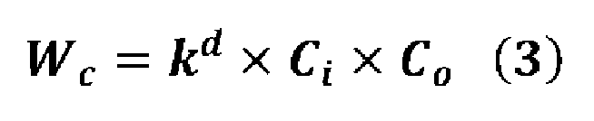


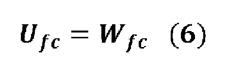
従来のDNNの計算コストが大きい理由は、ネットワークを構成する層を主に直列に並べ、その大半の層が畳み込み層からなる点にある。ネットワークの中間層においても、重み係数の個数が多く、乗算数も増加している。中間層の出力は人間による解釈が困難なテンソルとなっており、中間層の出力が必ずしも認識に最適な表現となっていない。換言すると、中間層に必要以上の重み係数が存在し、乗算数も増加している。すなわち、中間層において、人の行動或いは空間の状態を少ないパラメータで効果的に表現することにより、重み係数の個数の減少及び乗算数の減少を図ることが可能となる。
人の行動を識別する場合を考えると、密なデータである入力画像ではなく、人の骨格情報からも行動を推定することは可能である。例えば、包丁で食材を切るという行動は、特徴的な手の上下移動の反復である。入力画像データの表現に必要なデータ数(バイト数)は、8bitの画像データの場合、画像データの縦の長さと横の長さとチャンネル数との積となる。一方、二次元の骨格情報であれば、骨格の頂点(例えば、17点)の個数と、骨格の頂点の座標データ(x,y)の成分数との積である34で表現可能となる。
上記を考慮し、以下、本発明の実施の形態における認識器111の選定方法を説明する。認識対象となる人の行動は例えば、歩く、走る、立つ、会話する、掃除する、料理を開始するといった動作の他、例えば、寝ている、横になっている、座っている、テレビを見ている等の静止した行動も含まれる。
まず、認識器111の選択肢が多いことについて説明する。第1行動認識部104で使用する認識器111の個数は少なくとも一つである。第1行動認識部104がN個の認識器111を保持し、M個の認識器111を選択する場合の認識器111の組み合わせはNの階乗オーダーとなる。Nの階乗オーダーは指数関数よりも発散が速い。学習時間を考慮すると、Nが5程度より大きくなると全ての認識器111の組み合わせを学習することが困難になる。
次に、認識器111の組み合わせに関する問題を、数学的な問題として表現する。選択された認識器111の組み合わせ毎に、学習を行うことで認識精度と計算コストとが得られる。満たすべき認識精度(例えば、70%)が与えられ、その認識精度を満たす中で、計算コストが最小となる組み合わせを探すことは、条件付きの組み合わせ最適化問題となる。このような組み合わせ最適化問題は、組み合わせの個数が全探索の困難な個数になると、解析的に解くことができなくなる。したがって、準最適解を探索することになる。なお、組み合わせ最適化問題に対する万能なアルゴリズムは存在しない。
そこで、認識器111の選択を効率的に探索するために、事前知識と貪欲法とに基づき認識器111を選択する。
まず、事前知識に関して説明する。図10は、認識器111に関する情報を纏めた事前知識テーブルT4のデータ構成を示す図である。このテーブルはメモリ200に記憶されている。事前知識テーブルT4は、認識器111の識別番号、認識内容、入力センサデータ、相対計算コスト、及び認識器の依存関係に関する項目を有する。各項目について説明する。識別番号は登録されている認識器111に対して重複のない番号(例えば、連番)が与えられ、組み合わせ探索におけるインデックスまたはハッシュとなる。認識内容は、認識器111が認識する内容である。入力センサデータは認識器111が推論をするために必要となるセンサデータであり、0個以上である。0を含むのは、依存する他の認識器111が算出した特徴量のみで推論する認識器111は、センサデータを必要としないためである。相対計算コストは、認識器111の計算コストの相対値である。相対計算コストは、基準となる計算機で実行されたベンチマーク結果を元に算出された相対値である。なお、相対計算コストは、複数の計算機のベンチマーク結果に基づいて算出されてもよいし、ベンチマーク結果そのものである絶対値が採用されてもよい。
認識器の依存関係は、他の認識器111に依存するか否かを示す情報である。例えば、識別番号が4~6の認識器111は識別番号が3の認識器111に依存する。これは、頭向き推定、年齢性別推定、及び個人推定を行う場合、顔検出の結果が利用されるからである。
なお、手又は足の検出する認識器111のように、人の特定領域を検出する認識器111が用いられてもよい。また、画像の範囲を示すマスクのような密なデータを出力する認識器111が用いられてもよい。
次に、貪欲法について説明する。貪欲法とは、部分的な情報に基づき、最良な選択をする手法である。認識器111の選定では、まず、事前知識テーブルT4に含まれる各認識器111について、認識器111を一つのみ選択した時の認識精度を、学習データを用いて計算する。ある一つの認識器111のみ使用した場合の認識精度が高い場合、その認識器111を他の認識器111と組み合わせて使用した場合の認識精度も高いことが期待される。但し、その保証はない。貪欲法では、認識器111を一つのみ使用した場合の認識精度が高い場合、その認識器111を他の認識器111と組み合わせて使用した場合の認識精度も高いと仮定し、評価対象となる認識器111の組み合わせの優先順位が決定される。具体的には、認識器111を一つのみ使用した場合の認識精度の降順に認識器111をソートし、先頭の認識器111から優先的に評価する。例えば、先頭を1番目の認識器111とし、順にインデックスを振った場合、1と2、1と3、1~3、1~4、のように、先頭に近いインデックスを優先的に使用する。より詳細なインデックスの選択方法は、先頭からX番目のインデックスまで考慮するパラメータXと、Y個までのインデックスの選択を許容するパラメータYで表現できる。このXとYのパラメータは推論を実行する計算機の性能に応じて決定され、一例として、X=4、Y=3がある。図5に示す認識器選択テーブルT2は、例えば以上のような認識器111の選定結果に基づいて作成される。
(分類器の選定)
次に、分類器122の選定について説明する。第1行動認識部104が出力する特徴量は骨格情報のように、少ないパラメータをベクトル化したデータであるため、CNNを用いなくても識別可能である。分類器122はCNNに比べて計算処理量が大幅に少ない。複数の分類器の候補に対して交差検証(クロスバリデーション)を行い、正確度(Accuracy)又はF1スコアが最大となる分類器122を選定すればよい。候補となる分類器122は、例えばロジスティクス回帰、サポートベクターマシン(SVM)、決定木、ランダムフォレスト、k近傍法、ガウシアンナイーブベイズ、パーセプトロン、又は確率的降下法を用いた分類器である。
次に、分類器122の選定について説明する。第1行動認識部104が出力する特徴量は骨格情報のように、少ないパラメータをベクトル化したデータであるため、CNNを用いなくても識別可能である。分類器122はCNNに比べて計算処理量が大幅に少ない。複数の分類器の候補に対して交差検証(クロスバリデーション)を行い、正確度(Accuracy)又はF1スコアが最大となる分類器122を選定すればよい。候補となる分類器122は、例えばロジスティクス回帰、サポートベクターマシン(SVM)、決定木、ランダムフォレスト、k近傍法、ガウシアンナイーブベイズ、パーセプトロン、又は確率的降下法を用いた分類器である。
(分類器の学習)
次に、分類器122の学習について説明する。分類器122は対象行動のラベルを含む学習データを用いて学習すれば良い。例えば、「料理を開始する」と「料理を開始していない」とのそれぞれのラベルに対して学習データとなる動画の画像データを用意する。用意した画像データを用いて、図9に示す行動認識処理を行動認識装置1に実行させ、得られたラベルと学習データの正解ラベルとを比較し、その誤差が最小になるように、分類器122の重みを更新する。
次に、分類器122の学習について説明する。分類器122は対象行動のラベルを含む学習データを用いて学習すれば良い。例えば、「料理を開始する」と「料理を開始していない」とのそれぞれのラベルに対して学習データとなる動画の画像データを用意する。用意した画像データを用いて、図9に示す行動認識処理を行動認識装置1に実行させ、得られたラベルと学習データの正解ラベルとを比較し、その誤差が最小になるように、分類器122の重みを更新する。
(シミュレーション)
次に、行動認識装置1が、既存の行動推定AIより計算処理量が少ないことを確認するために行ったシミュレーションについて説明する。
次に、行動認識装置1が、既存の行動推定AIより計算処理量が少ないことを確認するために行ったシミュレーションについて説明する。
このシミュレーションでは、既存の認識器111としてCNNが用いられた。具体的には、姿勢推定の認識器111として「1:PoseNet」を用い、物体検出の認識器111として、「2:SSD」を用い、顔検出の認識器111として「3:RetinaFace」を用い、頭向き推定の認識器111として「4:DeepHeadPose」を用いた。分類器122としては確率的降下法の分類器が用いられた。一方、既存の行動推定AIとして「5:RepresentationFlowNet」が用いられた。
入力画像データとしては、3名の人を含む1枚のカラーの画像データが用いられた。この画像データは、解像度が640×480、チャンネル数が3、分解能が8bitであった。分類器122の計算コストは、識別するクラス数によらず、既存の認識器111に比べて十分小さいため無視した。
計算機は、グラフィックスプロセスユニット(製品型番:Geforce GTX 1080Ti)による計算補助を含むデスクトップ型のパーソナルコンピュータが使用された。
図11は、既存の認識器111を個別に実行した場合の1フレームあたりの処理時間を纏めたテーブルである。シミュレーションでは、図11の処理A(姿勢推定)、処理B(物体検出)、処理C(頭向き検出)のそれぞれの認識器111を実行したときの処理時間が計測された。処理Cの処理時間は頭向き推定と顔検出との処理時間が含まれる。処理A、B、Cは互いに独立した処理のため、並列実行可能である。オーバーヘッドを無視した場合、処理A、B、Cのうち処理時間の最大値は処理Cの0.0455秒であった。一方、処理A、B、Cを逐次処理した場合の全体の処理時間は0.0725秒であった。
これに対し、処理D(既存の行動推定AI)のの処理時間は0.1429秒であった。したがって、処理A、B、Cを並列処理した場合の処理速度は、処理Dの3倍であった。処理A、B、Cを逐次処理した場合の処理速度は処理Dの2倍であった。このように、複数の認識器111を用いた方が、既存の行動推定AIよりも処理速度が大幅に速くなることが確認できた。
次に、行動認識装置1の認識精度を評価するために行われたシミュレーションについて説明する。このシミュレーションでは、入力画像データとして図12に示す5本の動画の画像データが用いられた。図12は、入力画像データを纏めた表である。ビデオIDは5本の動画を識別するための識別子である。図12では、各動画について「料理を開始する」のフレームと「料理を開始していない」のフレームとのそれぞれの総数が示されている。
図13は、行動認識装置1の認識精度を評価するために行われたシミュレーションの結果を纏めた表である。図13において、例えば処理A+B+Cは、第1行動認識部104を処理Aの認識器111、処理Bの認識器111、処理Cの認識器111で構成した場合を示し、例えば処理A+Bは、第1行動認識部104を処理Aの認識器111と処理Bの認識器111とで構成した場合を示している。このシミュレーションでは、図13で示す処理A~Cの組み合わせのそれぞれについて、8種類の分類器122のそれぞれの認識精度及び処理時間が計測された。8種類の分類器122は、ロジスティクス回帰、サポートベクターマシン、決定木、ランダムフォレスト、k近傍法、ガウシアンナイーブベイズ、パーセプトロン、及び確率的降下法である。このシミュレーションでは、8種の分類器122のうち、確率的降下法の分類器122を採用した場合の処理時間が最も短く、認識精度も最大であった。
また、確率的降下法の分類器122を用いた場合において、図13に示す処理A~Cの各組み合せのうち認識精度の平均値は88.5%であった。この結果は、行動認識装置1の認識精度が「料理を開始する」と「料理を開始していない」との2クラス分類をランダムに推定した場合の認識精度の期待値である50%より高いことを示す。したがって、このシミュレーション結果から行動認識装置1は、行動を認識できることが確認できた。
図13に示す各組み合わせのうち、認識精度が最良なのは、処理A+Cで88.8%であった。しかし、処理Aのみでも88.7%の認識精度が得られた。仮に認識精度の閾値を88.7%とすると、処理Aのみ用いた場合、計算コストが最小になる。処理A+B+Cが最良ではないのは、精度の向上に貢献しない認識器111があり、その認識器111がノイズ源のように振る舞ったからである。
以上のシミュレーション結果は、一例であり、第1行動認識部104を構成する各認識器111は上述したものに限定されず、対象行動に応じて適宜最適な認識器111が採用される。また、分類器122も確率的降下法以外の分類器122が採用されてもよい。
(変形例)
(1)上記実施の形態では、行動認識装置1は、単体で構成されたが、本開示はこれに限定されず、複数の装置で構成されてもよい。図14は、本開示の変形例に係る行動認識装置1Aの構成の一例を示すブロック図である。行動認識装置1Aは、サーバで構成されている。行動認識装置1Aは、通信部500をさらに備える。通信部500は、出力部106が出力する認識結果をネットワークNT及びゲートウェイ700を介して家電機器600に送信する。通信部500は、宅内に設置された画像センサ300が撮影した画像データを受信する。ネットワークNTは、例えばインターネット等の広域通信網である。ゲートウェイ700は宅内に設置され、画像センサ300及び家電機器600をネットワークNTに接続する。家電機器600は、洗濯機、電子レンジ、及びテレビ等である。家電機器600は、行動認識装置1Aから送信された行動の認識結果を利用した制御を実行したり、認識結果を表示したりする。このように、行動認識装置1Aはサーバで構成された場合においても、宅内の人の行動を認識できる。
(2)上記実施の形態では、入力データとして画像データが用いられたがこれに加えて、熱画像データ、奥行画像データ、音声データ、室温データ、湿度データ、照度データ、無線の電波のデータのうちの少なくとも1つが用いられてもよい。
(3)宅内における人の行動を宅内に設置したカメラで認識する場合、カメラの設置位置及びアングルは、固定又は低い頻度で変更されることが想定される。また、カメラの視野角は広角レンズの場合で110°程度、狭角レンズの場合はそれ以下となり、あるカメラに映る範囲は設置された空間の一部となる。このため、認識したい行動の発生頻度が高い、或いは発生時の重要度が高い空間が撮影されるようにカメラは設置されることが想定される。これらの想定において、カメラが設置されている空間と、カメラに映る或いは映る可能性がある物体とを事前に知ることができれば、行動の認識精度が向上する。例えば、発生頻度が0の行動は、認識対象から除外することができる。また、移動頻度が低いソファーがカメラに映っている場合はそこに座るという行動が発生する頻度が高いことが想定される。また、移動可能な椅子が空間内に存在している場合、椅子に座るという行動の頻度が高いことが想定される。これにより、図6に示す重みテーブルT3の重み係数の値を決定することが可能となる。
宅内における行動認識において、人と物体との直接的な接触或いは物体の近傍に人がいるという人と物体とのインタラクションが重要である。物体の移動、開閉、操作を伴う物体(後述の第1物体)の設置位置が既知の場合、人がその物体に対してどのような位置関係又は向きにいるかということが、行動認識の判断材料となる。これは人が行動の際に、物体の移動、開閉、及び操作を行うことが多いことに基づく。
水回り設備に代表される宅内の移動できない設備(後述の第2物体)も行動認識において重要である。料理又は洗面といった水を使用する行動は通常、宅内に設置された設備を使用する。そのため、水回りの設備の位置と、人の位置関係とが行動認識の判断材料となる。これは人の生活において、水を必要とする行動の頻度が高いということに基づく。
住居は一般的に4~10個程度の部屋にドア又は固定若しくは可動式の壁で区切られる。また、多層式の住居は、階段等の昇降設備を備える。このため、住居は複数の空間及び多数のドアを含む物体(後述の第3物体)を有する。これらの空間の名称と、ドア又は昇降設備の位置と、人との位置関係が行動認識の判断材料となる。これは、調理又は入浴のように特定の部屋でのみ実施する行動があることに基づく。
上述したように、物体又は設備がどこにあり、どのように空間が区切られているかという情報が行動認識において重要である。従来、リビングや寝室といった空間名を考慮に入れて行動認識を行う技術はあったが、同じ空間名であっても使われ方は多様であり、リビング又は寝室という空間名のみでは、行動認識の判断材料としては不十分である。そのため、どの空間でどのような人と物体とのインタラクションが起こり得るかを考慮することが重要である。これらのことを踏まえて、以下、本開示の変形例(3)について説明する。
図15は、本開示の変形例(3)に係る行動認識装置1Bの構成の一例を示すブロック図である。この変形例は、間取り情報202に基づいて、間取り特徴量を抽出し、抽出した間取り特徴量に基づいて行動選択テーブルT1を生成するものである。この変形例では間取り情報202は、建物内の空間の情報に加えて、各空間に設置された物体(設備及び機器)の情報(種別情報及び位置情報)も含んでいる。
行動認識装置1Bは、表示端末400と所定の通信路を介して通信可能に接続されている。所定の通信路としては、無線LAN、Bluetooth(登録商標)が採用できる。また、所定の通信路は、インターネットであってもよい。表示端末400は、例えば、スマートフォン又はタブレット型コンピュータで構成される。表示端末400は、例えばユーザにより所持される。ユーザは例えば、画像センサ2の施工者である。施工者は、例えば住居の居住者又は施工業者である。
行動認識装置1Bのプロセッサ100Bは、図1に対してさらに、設置支援部301及び間取り特徴量抽出部302を含む。間取り特徴量抽出部302は、間取り情報202に基づいて、建物に設置された物体を抽出し、抽出した物体を、移動可能な第1物体、水回り設備である第2物体、建物の構造物である第3物体のいずれかに分類し、分類した物体のそれぞれについて、設置位置と、分類結果を示す分類情報とが対応付けられた間取り特徴量を抽出する。間取り特徴量は、例えば2次元テーブルで構成される。
第1物体は、例えば、家具及び電気製品等の移動可能な物体を含む。具体的には、第1物体は、掃除機、コーヒーメーカ、ノートパソコン、椅子、及びソファーなどである。
第2物体は、例えばシンク及び洗面台等の移動不可能な水回り設備などである。
第3物体は、玄関、キッチン、リビング、ダイニング、ベッドルーム、バスルーム、昇降設備、及び洗面所等の建物の構造物である。
設置位置は、例えば建物の玄関を基準とする2次元又は3次元の座標データで構成される。なお、第3物体の設置位置は、第3物体が位置する領域を示す座標データで構成されてもよい。これにより、第1物体及び第2物体が建物内のどの空間に設置するかを判定できる。なお、第1物体及び第2物体の設置位置は、第1物体及び第2物体が位置する座標データに加えて、第1物体及び第2物体が位置する建物の空間の名称を含んでいてもよい。
分類情報は、間取り情報202から抽出される物体が、第1物体~第3物体のいずれに該当するかを示す情報である。
間取り特徴量抽出部302は、抽出した間取り特徴量に基づいて、行動選択テーブルT1を生成する。
例えば、第1物体の設置位置は、ユーザが動作する位置を示す。例えば、コーヒーメーカの設置位置はコーヒーを淹れる行動に対応付けることができる。例えば、電子レンジの設置位置は、ユーザが料理を開始する行動に対応付けることができる。
また、第2物体は水回り設備であるため、第2物体の設置位置は、水を使用する動作が行われる位置を示す。例えば、シンクの設置位置は、皿を洗う行動に対応付けることができる。
第3物体の設置位置は、空間の名称と、ユーザの空間への出入りと、ユーザが移動可能な範囲を示す。例えば、浴室のドアの設置位置は入浴動作に対応付けることができる。
間取り特徴量抽出部302は、抽出した間取り特徴量に基づいて、行動選択テーブルを生成する。行動選択テーブルT1は、図4に示すように建物内の1以上の空間と各空間においてユーザが行う可能性の高い対象行動とが対応付けられたテーブルである。
ここで、間取り特徴量抽出部302は、間取り特徴量から、各空間にどのような機器又は設備が設置されているかを決定し、決定結果と分類情報とから予め定められたルールを参照することで、行動選択テーブルT1を生成すればよい。ルールとしては、例えば、第1物体である電子レンジに対して料理を温める、第1物体であるコーヒーメーカに対してコーヒーを淹れる、第2物体であるシンクに対して皿洗いというように、機器又は設備と機器又は設備で行われる可能性の高い対象行動とが対応付けられたルールが採用できる。
例えば、キッチンに、電子レンジ、コーヒーメーカ、及びシンクが設置されているとする。この場合、間取り特徴量抽出部302は、キッチンについて、料理を開始する、コーヒーを淹れる、皿洗いをするといった対象行動が対応付けられた行動選択テーブルT1を生成すればよい。なお、間取り特徴量抽出部302は、建物内の他の空間についても同様にして対象行動を対応付ければよい。
また、ルールは、機器又は設備のみならず、空間自体に対して行われる可能性の高い対象行動を含んでいてもよい。例えば、図4で説明したように、キッチンに対して料理を開始する、洗面所に対して洗濯、リビング、ダイニング、及びベッドルームに対して読書、リビング及びダイニングに対して食事といったルールが採用できる。
さらに、間取り特徴量抽出部302は、抽出した間取り特徴量から図6に示す重みテーブルT3に記載された重み係数を設定してもよい。例えば、キッチンに、シンク、冷蔵庫、電子レンジ、及びガスコンロが設置されている場合、キッチンについての重み係数Weは、シンク、冷蔵庫、電子レンジ、及びガスコンロについて1、それ以外の機器については0に設定すればよい。
間取り特徴量抽出部302は、キッチン以外の他の空間についてもキッチンと同様に重み係数Weを設定すればよい。
なお、第1取得部101は、このようにして生成された行動選択テーブルT1を対象行動情報として取得すればよい。
設置支援部301は、画像センサ2が設置される建物の空間の名称を表示端末400を介して取得し、空間に関連する特定機器又は特定設備が画像センサ2の視野内に含まれるように画像センサ2を設置する設置ガイダンスを表示端末400に出力する設置支援部をさらに備える。
図16は、玄関501に画像センサ2が設置されるシーンを示す図である。図17は、玄関501に画像センサ2が設置されるシーンにおいてユーザと表示端末400とのインタラクションの一例を示す図である。
ステップST1において、表示端末400は、設定画面を開く操作をユーザから受け付け、画像センサ2の設置が予定される空間を一覧表示する。ここでは、A:玄関、B:キッチン、C:リビング、・・・というように画像センサ2が設置される空間の名称が一覧表示される。
ステップST2において、表示端末400は、一覧表示された空間の名称の中から画像センサ2が設置される空間の名称を選択するユーザの操作を受け付ける。表示端末400は、選択された空間の名称を行動認識装置1Bに送信する。ここでは、画像センサ2は玄関501に設置されるため、「A:玄関」が選択される。
ステップST3において、表示端末400は、「ドアが映る位置に設置して下さい。設置後、OKを押して下さい。」というように、ユーザに画像センサ2の設置を促すメッセージを表示する。設定画面には、このメッセージに併せて、ユーザが画像センサ2の設置作業が完了したことを表示端末400に知らせるためのOKボタンが表示されている。
この設置作業により、図16に示すように、玄関501に画像センサ2が設置される。
ステップST4において、表示端末400は、OKボタンを押すユーザの操作を受け付ける。OKボタンを押す操作を受け付けた表示端末400は、OKボタンが押されたことを示す情報を行動認識装置1Bに送信する。
OKボタンが押されたことを示す情報を取得した設置支援部301は、画像センサ2が撮影した画像データを取得し、取得した画像データからドア401を検出する処理を実行する。このとき、設置支援部301は、表示端末400に、「ドアを自動検出しています。」というメッセージを表示させる(ステップST5)。ここで、設置支援部301は、所定の認識器を用いてドア401を検出すればよい。ドア401は玄関501における特定設備の一例である。特定設備は、画像センサ2が設置される空間に応じて予め定められている。所定の認識器としては、例えばドア401を検出するために予め準備された認識器が採用される。
図18は、図17に続くインタラクションを示す図である。ステップST6において、表示端末400は、ドア401の検出結果を示すアノテーション情報を設置支援部301から取得し、取得したアノテーション情報が示すアノテーション画像を、画像センサ2が撮影した画像に重畳表示する設定画面を表示する。この設定画面には、「自動検出された赤色ドアガイドの位置のドアに合わせるように調整し、OKを押してください」というように、アノテーション画像の修正を促すメッセージが表示されている。アノテーション情報は、例えばアノテーション画像の座標データである。
図19は、アノテーション画像A1が重畳された設定画面G1、G2の一例を示す図である。設定画面G1は修正前のアノテーション画像A1を示し、設定画面G2は修正後のアノテーション画像A1を表示する。アノテーション画像A1は、四角形のバウンディングボックスで構成されている。アノテーション画像A1は所定の色(ここでは、赤色)を有している。設定画面G1、G2には、アノテーション画像A1の修正作業の完了を告げるOKボタン1901が表示されている。
アノテーション画像A1の左上の頂点には丸マークP1が表示され、アノテーション画像A1の右下の頂点には丸マークP2が表示されている。
表示端末400は、丸マークP1、P2を移動する操作を受け付けると、受け付けた操作に連動させてアノテーション画像A1のサイズを変更する。
設定画面G1では認識器によるドア401の検出結果であるアノテーション画像A1が表示されている。このアノテーション画像A1は、ドア401よりも左斜め上側にずれており、ドア401が正しく認識できていないことが分かる。
ユーザは、アノテーション画像A1の形状がドア401の外接矩形となるように、丸マークP1、P2を移動する操作を入力する。これにより、設定画面G2が得られる。設定画面G2では、アノテーション画像A1がドア401の外接矩形に位置決めされている。
これにより、設定画面G1においてドア401からずれた位置に表示されていたアノテーション画像A1が、設定画面G2に示すようにドア401の全域を取り囲むように修正される。その結果、認識器がドア401の画像上の位置を正確に認識できていない場合においても、認識器にドア401の画像上の正しい位置が得られる。
ステップST7において、表示端末400は、アノテーション画像A1の調整が完了したユーザから、OKボタン1901を押す操作を受け付ける。この操作を受け付けた表示端末400は、修正されたアノテーション画像A1の座標データを設置支援部301に送信する。この座標データを受信した設置支援部301は、修正されたアノテーション画像A1の座標データを玄関501に設置された画像センサ2の位置情報203と対応付けてメモリ200に記憶する。
以後、玄関501に対応する対象行動を認識するための認識器111は、玄関501に設置された画像センサ2により撮影された画像データに対して、座標データが示すアノテーション画像A1を基準にしてユーザの行動を認識する。これにより、認識器111は効率良くユーザの行動を認識することができる。
ステップST8において、表示端末400は、設置支援部301から座標データを保存したことを示す情報を受信したため、「設定を保存しました。」とのメッセージを表示する。
ステップST9において、表示端末400は、ユーザから設定画面を閉じる操作を受け付ける。これにより、表示端末400は、設定画面を閉じる。
図20は、キッチン502に画像センサ2が設置されるシーンを示す図である。図21は、キッチン502に画像センサ2が設置されるシーンにおいてユーザと表示端末400とのインタラクションの一例を示す図である。
ステップST1は、図17のステップST1と同じである。ステップST2において、表示端末400は、ユーザから画像センサ2の設置場所として「B:キッチン」を選択する操作を受け付ける。
ステップST3は、図17のステップST3と同じである。ステップST4において、表示端末400は、OKボタンを押すユーザの操作を受け付ける。OKボタンを押す操作を受け付けた表示端末400は、OKボタンが押されたことを示す情報を行動認識装置1Bに送信する。
OKボタンが押されたことを示す情報を取得した設置支援部301は、画像センサ2が撮影した画像データを取得し、取得した画像データから冷蔵庫402を検出する処理を実行する。これにより、設置支援部301は、表示端末400に、「冷蔵庫を自動検出しています。」というメッセージを表示させる(ステップST5)。ここで、設置支援部301は、所定の認識器を用いて冷蔵庫402を検出すればよい。冷蔵庫402はキッチン502における特定機器の一例である。特定機器は、画像センサ2が設置される空間に応じて予め定められている。所定の認識器としては、例えば冷蔵庫402を検出するために予め準備された認識器が採用される。
図22は、図21に続くインタラクションを示す図である。ステップST6~ST9は図18と同じである。図23は、アノテーション画像A1が重畳された設定画面G3、G4の一例を示す図である。設定画面G3は修正前のアノテーション画像A1を表示し、設定画面G3は修正後のアノテーション画像A1を表示する。設定画面G3では認識器による冷蔵庫402の検出結果であるアノテーション画像A1が表示されている。このアノテーション画像A1は、冷蔵庫402よりも上側にずれており、冷蔵庫402が正しく認識できていないことが分かる。ユーザは、アノテーション画像A1の形状が冷蔵庫402の外接矩形となるように、丸マークP1、P2を移動する操作を入力する。これにより、設定画面G4が得られる。設定画面G4では、アノテーション画像A1が冷蔵庫402の外接矩形に位置決めされている。
これにより、設定画面G3において冷蔵庫402からずれた位置に表示されていたアノテーション画像A1が、設定画面G4に示すように冷蔵庫402の全域を取り囲むように修正される。その結果、認識器が冷蔵庫402の画像上の位置を正確に認識できていない場合においても、冷蔵庫402の画像上の正しい位置が得られる。
以後、冷蔵庫402に対応する対象行動を認識するための認識器111は、冷蔵庫402に設置された画像センサ2により撮影された画像データに対して、座標データが示すアノテーション画像A1を基準にしてユーザの行動を認識する。これにより、認識器111は効率良くユーザの行動を認識することができる。
図24は、画像センサ2の設置後にアノテーション画像A1を修正する際のユーザと表示端末400とのインタラクションの一例を示す図である。画像センサ2は設置後に何らかの外力が加えられてアングルが変動することがある。この場合、設置時に設定されたアノテーション画像A1が示す座標データは、特定機器又は特定設備の画像上の位置からずれてしまう。このずれを修正するために以下の修正作業が行われる。
ステップST1において、表示端末400は、設定画面を開く操作をユーザから受け付け、画像センサ2の位置ずれの確認を促すメッセージを表示する。ここでは、「カメラ位置がずれていないか確認してください。赤色ガイドが現在の設定です。水色ガイドが自動検出した位置です」とのメッセージが表示されている。
図25は、アノテーション画像A1が重畳表示された設定画面G5、G6の一例を示す図である。設定画面G5は、修正前のアノテーション画像A1を示し、設定画面G6は、修正後のアノテーション画像A1を示している。アノテーション画像A1は赤色ガイドに相当する。点線のアノテーション画像A2は認識器による冷蔵庫402の検出結果であるアノテーション画像を示している。アノテーション画像A2は水色ガイドに相当する。
設定画面G5において、画像センサ2のアングルが設置時のアングルに対してずれたため、アノテーション画像A1は、アノテーション画像A2に対して上側にずれて表示されている。
ステップST2において、ユーザは設定画面G5から画像センサ2のアングルのずれを確認し、画像センサ2のアングルの調整作業を行う。
表示端末400は、アノテーション画像A1の位置がアノテーション画像A2の位置と一致するか否かを画像処理により判定する。表示端末400は、一致したと判定した場合、画像センサ2のアングルが設置時のアングルに戻ったことを示すメッセージを表示する。
ステップST4において、表示端末400は、ユーザから設定画面を閉じる操作を受け付ける。これにより、表示端末400は、設定画面を閉じる。
このような調整作業をユーザに行わせることで、設置後に画像センサ2のアングルが変動した場合であっても、画像センサ2のアングルを設置時のアングルに戻すことができる。これにより、認識器111はユーザの行動を正確に認識することができる。
本発明の行動認識装置は、建物において人の行動を認識する際に有用である。
Claims (12)
- 建物における人の行動を認識する行動認識装置であって、
予め定められた認識対象となる1以上の対象行動を含む対象行動情報と、前記建物の間取り情報と、前記建物に設置された画像センサの位置情報とを取得する第1取得部と、
前記画像センサの位置情報と前記間取り情報とに基づいて前記対象行動情報に含まれる前記1以上の対象行動の中から認識候補となる候補行動を選択する行動選択部と、
前記画像センサが検出した画像データを取得する第2取得部と、
前記候補行動に応じた1以上の認識器を決定し、前記1以上の認識器を用いて前記画像データの特徴量を算出する第1行動認識部と、
前記特徴量に基づいて前記候補行動を認識する第2行動認識部と、
前記第2行動認識部による認識結果を出力する出力部とを備える、
行動認識装置。 - 前記第1行動認識部は、前記候補行動が所定の行動である場合、複数の認識器を決定し、
前記第2行動認識部は、前記複数の認識器がそれぞれ算出した特徴量を結合し、結合した特徴量に基づいて前記候補行動を認識する、
請求項1記載の行動認識装置。 - 前記所定の行動は、掃除、歯磨き、料理、洗濯、コンピュータの使用、読書、又は食事である、
請求項2記載の行動認識装置。 - 各認識器は、コンボリューションニューラルネットワークで構成され、
前記第2行動認識部は、ロジスティクス回帰、サポートベクターマシン、決定木、ランダムフォレスト、k近傍法、ガウシアンナイーブベイズ、パーセプトロン、及び確率的降下法のいずれか1つを用いた分類器を用いて前記候補行動を認識する、
請求項1~3のいずれかに記載の行動認識装置。 - 前記第2行動認識部は、前記特徴量を説明変数とし、前記対象行動を目的変数として機械学習された分類器を用いて前記候補行動を認識する、
請求項1~4のいずれかに記載の行動認識装置。 - 前記第2行動認識部は、前記候補行動に応じて予め定められた重み係数を用いて各特徴量に重み付けをし、重み付け後の各特徴量に基づいて前記候補行動を認識する、
請求項1~5のいずれかに記載の行動認識装置。 - 前記間取り情報から、前記建物に設置された1以上の物体を抽出し、前記1以上の物体を、移動可能な第1物体、水回り設備である第2物体、及び前記建物の構造物である第3物体のいずれかに分類し、前記1以上の物体のそれぞれについて、分類結果を示す分類情報と設置位置とが対応付けられた間取り特徴量を抽出し、前記間取り特徴量に基づいて、行動選択テーブルを生成し、
前記行動選択テーブルは、前記建物の1以上の空間と、各空間に対応する前記対象行動とが対応付けられたテーブルであり、
前記第1取得部は、前記行動選択テーブルを前記対象行動情報として取得する、
請求項1~6のいずれかに記載の行動認識装置。 - 前記行動認識装置は表示端末と通信可能に接続され、
前記画像センサが設置される前記建物の空間の名称を前記表示端末を介して取得し、前記空間に関連する特定機器又は特定設備が前記画像センサの視野内に含まれるように前記画像センサを設置する設置ガイダンスを前記表示端末に出力する設置支援部をさらに備える、
請求項7記載の行動認識装置。 - 前記設置支援部は、前記画像センサが撮影した画像データを取得し、前記画像データに含まれる前記特定機器又は前記特定設備を検出し、前記特定機器又は前記特定設備の検出結果を示すアノテーション画像を、前記画像データが示す画像に重畳表示させる、
請求項8記載の行動認識装置。 - 前記設置支援部は、前記アノテーション画像の修正指示を前記表示端末を介して取得し、修正された前記アノテーション画像が示すアノテーション情報をメモリに記憶する、
請求項9記載の行動認識装置。 - 建物におけるユーザの行動を認識する行動認識方法であって、
コンピュータが、
予め定められた認識対象となる1以上の対象行動を含む対象行動情報を取得し、
前記建物の間取り情報を取得し、
前記建物に設置された画像センサの位置情報を取得し、
前記画像センサの位置情報と前記間取り情報とに基づいて前記対象行動情報に含まれる前記1以上の対象行動の中から認識候補となる候補行動を選択し、
前記画像センサが検出した画像データを取得し、
第1行動認識部が、前記候補行動に応じた1以上の認識器を決定し、前記1以上の認識器を用いて前記画像データの特徴量を算出し、
第2行動認識部が、前記特徴量に基づいて前記候補行動を認識し、
前記第2行動認識部による認識結果を出力する、
行動認識方法。 - 建物におけるユーザの行動を認識するためのプログラムであって、
予め定められた認識対象となる1以上の対象行動を含む対象行動情報と、前記建物の間取り情報と、前記建物に設置された画像センサの位置情報とを取得する第1取得部と、
前記画像センサの位置情報と前記間取り情報とに基づいて前記対象行動情報に含まれる前記1以上の対象行動の中から認識候補となる候補行動を選択する行動選択部と、
前記画像センサが検出した画像データを取得する第2取得部と、
前記候補行動に応じた1以上の認識器を決定し、決定した1以上の認識器を用いて前記画像データの特徴量を算出する第1行動認識部と、
前記特徴量に基づいて前記候補行動を認識する第2行動認識部と、
前記第2行動認識部による認識結果を出力する出力部としてコンピュータを機能させる、
プログラム。
Priority Applications (3)
| Application Number | Priority Date | Filing Date | Title |
|---|---|---|---|
| CN202180046625.XA CN115803790A (zh) | 2020-07-10 | 2021-04-01 | 行动识别装置、行动识别方法以及程序 |
| JP2022534909A JP7741074B2 (ja) | 2020-07-10 | 2021-04-01 | 行動認識装置、行動認識方法、及びプログラム |
| US18/089,071 US20230127086A1 (en) | 2020-07-10 | 2022-12-27 | Behavior recognition device, behavior recognition method, and non-transitory computer-readable recording medium |
Applications Claiming Priority (2)
| Application Number | Priority Date | Filing Date | Title |
|---|---|---|---|
| JP2020-119202 | 2020-07-10 | ||
| JP2020119202 | 2020-07-10 |
Related Child Applications (1)
| Application Number | Title | Priority Date | Filing Date |
|---|---|---|---|
| US18/089,071 Continuation US20230127086A1 (en) | 2020-07-10 | 2022-12-27 | Behavior recognition device, behavior recognition method, and non-transitory computer-readable recording medium |
Publications (1)
| Publication Number | Publication Date |
|---|---|
| WO2022009489A1 true WO2022009489A1 (ja) | 2022-01-13 |
Family
ID=79552866
Family Applications (1)
| Application Number | Title | Priority Date | Filing Date |
|---|---|---|---|
| PCT/JP2021/014244 Ceased WO2022009489A1 (ja) | 2020-07-10 | 2021-04-01 | 行動認識装置、行動認識方法、及びプログラム |
Country Status (4)
| Country | Link |
|---|---|
| US (1) | US20230127086A1 (ja) |
| JP (1) | JP7741074B2 (ja) |
| CN (1) | CN115803790A (ja) |
| WO (1) | WO2022009489A1 (ja) |
Cited By (1)
| Publication number | Priority date | Publication date | Assignee | Title |
|---|---|---|---|---|
| JP2023178745A (ja) * | 2022-06-06 | 2023-12-18 | 日本電気株式会社 | 情報処理装置、情報処理方法、およびプログラム |
Families Citing this family (2)
| Publication number | Priority date | Publication date | Assignee | Title |
|---|---|---|---|---|
| CN112784760B (zh) * | 2021-01-25 | 2024-04-12 | 北京百度网讯科技有限公司 | 人体行为识别方法、装置、设备以及存储介质 |
| CN116824487A (zh) * | 2023-06-07 | 2023-09-29 | 杭州金通科技集团股份有限公司 | 一种电单车姿态检测方法及系统 |
Citations (2)
| Publication number | Priority date | Publication date | Assignee | Title |
|---|---|---|---|---|
| JP2016038774A (ja) * | 2014-08-08 | 2016-03-22 | シャープ株式会社 | 人物識別装置 |
| JP2018005752A (ja) * | 2016-07-07 | 2018-01-11 | 株式会社日立システムズ | 振る舞い検知システム |
Family Cites Families (14)
| Publication number | Priority date | Publication date | Assignee | Title |
|---|---|---|---|---|
| DE69736622T2 (de) * | 1996-07-03 | 2007-09-13 | Hitachi, Ltd. | System zur Bewegungserkennung |
| JP5403355B2 (ja) * | 2009-11-20 | 2014-01-29 | 清水建設株式会社 | 建物内の検知対象の位置検知、行動認知システム |
| DE102013204145A1 (de) * | 2013-02-27 | 2014-09-11 | Init Innovative Informatikanwendungen In Transport-, Verkehrs- Und Leitsystemen Gmbh | Anordnung und Verfahren zur Überwachung von Personenbewegungen in Gebäuden |
| US9305216B1 (en) * | 2014-12-15 | 2016-04-05 | Amazon Technologies, Inc. | Context-based detection and classification of actions |
| US11119722B2 (en) * | 2016-11-08 | 2021-09-14 | Sharp Kabushiki Kaisha | Movable body control apparatus and recording medium |
| JP2018078434A (ja) * | 2016-11-09 | 2018-05-17 | 富士通株式会社 | 送信装置、情報処理システムおよび送信方法 |
| JP6703199B2 (ja) * | 2017-10-27 | 2020-06-03 | 株式会社アシックス | 動作状態評価システム、動作状態評価装置、動作状態評価サーバ、動作状態評価方法、および動作状態評価プログラム |
| US10885589B2 (en) * | 2017-12-14 | 2021-01-05 | Mastercard International Incorporated | Personal property inventory captivator systems and methods |
| WO2019186676A1 (ja) | 2018-03-27 | 2019-10-03 | 株式会社日立製作所 | 行動推定および変化検出装置 |
| CN108985195A (zh) * | 2018-06-29 | 2018-12-11 | 平安科技(深圳)有限公司 | 行为识别方法、装置、计算机设备及存储介质 |
| US11380108B1 (en) * | 2019-09-27 | 2022-07-05 | Zoox, Inc. | Supplementing top-down predictions with image features |
| CN110930199A (zh) * | 2019-12-06 | 2020-03-27 | 西北工业大学 | 一种基于rfid感知的多用户购物行为识别方法 |
| CN113971628B (zh) * | 2020-07-24 | 2025-05-06 | 株式会社理光 | 图像匹配方法、装置和计算机可读存储介质 |
| US20220159934A1 (en) * | 2020-11-25 | 2022-05-26 | Kyndryl, Inc. | Animal health and safety monitoring |
-
2021
- 2021-04-01 CN CN202180046625.XA patent/CN115803790A/zh active Pending
- 2021-04-01 WO PCT/JP2021/014244 patent/WO2022009489A1/ja not_active Ceased
- 2021-04-01 JP JP2022534909A patent/JP7741074B2/ja active Active
-
2022
- 2022-12-27 US US18/089,071 patent/US20230127086A1/en active Pending
Patent Citations (2)
| Publication number | Priority date | Publication date | Assignee | Title |
|---|---|---|---|---|
| JP2016038774A (ja) * | 2014-08-08 | 2016-03-22 | シャープ株式会社 | 人物識別装置 |
| JP2018005752A (ja) * | 2016-07-07 | 2018-01-11 | 株式会社日立システムズ | 振る舞い検知システム |
Cited By (1)
| Publication number | Priority date | Publication date | Assignee | Title |
|---|---|---|---|---|
| JP2023178745A (ja) * | 2022-06-06 | 2023-12-18 | 日本電気株式会社 | 情報処理装置、情報処理方法、およびプログラム |
Also Published As
| Publication number | Publication date |
|---|---|
| JP7741074B2 (ja) | 2025-09-17 |
| CN115803790A (zh) | 2023-03-14 |
| JPWO2022009489A1 (ja) | 2022-01-13 |
| US20230127086A1 (en) | 2023-04-27 |
Similar Documents
| Publication | Publication Date | Title |
|---|---|---|
| JP7615584B2 (ja) | 視覚ベースの関節動作と姿勢運動の予想のためのシステム、コンピュータ実施方法、及びプログラム | |
| US20230127086A1 (en) | Behavior recognition device, behavior recognition method, and non-transitory computer-readable recording medium | |
| Bharti et al. | HuMAn: Complex activity recognition with multi-modal multi-positional body sensing | |
| KR102640420B1 (ko) | 홈 로봇 장치의 동작 운용 방법 및 이를 지원하는 홈 로봇 장치 | |
| Sung et al. | Unstructured human activity detection from rgbd images | |
| Piyathilaka et al. | Human activity recognition for domestic robots | |
| US9646340B2 (en) | Avatar-based virtual dressing room | |
| WO2021124314A1 (en) | System, method and computer program product for determining sizes and/or 3d locations of objects imaged by a single camera | |
| CN111643017B (zh) | 基于日程信息的清扫机器人控制方法、装置和清扫机器人 | |
| EP3284013A1 (en) | Event detection and summarisation | |
| JP7711441B2 (ja) | 行動認識プログラム、行動認識方法および情報処理装置 | |
| WO2018163555A1 (ja) | 画像処理装置、画像処理方法、及び画像処理プログラム | |
| Liang et al. | Functional workspace optimization via learning personal preferences from virtual experiences | |
| KR20200024675A (ko) | 휴먼 행동 인식 장치 및 방법 | |
| Yamazaki et al. | Bottom dressing by a dual-arm robot using a clothing state estimation based on dynamic shape changes | |
| WO2017005014A1 (zh) | 搜索匹配商品的方法及装置 | |
| Reddy et al. | Human activity recognition from kinect captured data using stick model | |
| JP2019219766A (ja) | 分析装置、分析システム、及び分析プログラム | |
| US20260042222A1 (en) | Robot for providing customized service and method thereof | |
| CN104598012B (zh) | 一种互动型广告设备及其工作方法 | |
| Wang et al. | PepperPose: Full-body pose estimation with a companion robot | |
| KR20260003622A (ko) | 조리 기기 및 그의 동작 방법 | |
| EP4125067B1 (en) | Generating program, generation method, and information processing device | |
| JP7259313B2 (ja) | 属性決定装置、属性決定システム、属性決定方法、プログラムおよび記録媒体 | |
| US20250201026A1 (en) | Cooking motion estimation device, cooking motion estimation method, and cooking motion estimation program |
Legal Events
| Date | Code | Title | Description |
|---|---|---|---|
| 121 | Ep: the epo has been informed by wipo that ep was designated in this application |
Ref document number: 21838674 Country of ref document: EP Kind code of ref document: A1 |
|
| ENP | Entry into the national phase |
Ref document number: 2022534909 Country of ref document: JP Kind code of ref document: A |
|
| NENP | Non-entry into the national phase |
Ref country code: DE |
|
| 122 | Ep: pct application non-entry in european phase |
Ref document number: 21838674 Country of ref document: EP Kind code of ref document: A1 |