WO2022004694A1 - 無線通信システム、無線通信装置、および、無線通信方法 - Google Patents
無線通信システム、無線通信装置、および、無線通信方法 Download PDFInfo
- Publication number
- WO2022004694A1 WO2022004694A1 PCT/JP2021/024470 JP2021024470W WO2022004694A1 WO 2022004694 A1 WO2022004694 A1 WO 2022004694A1 JP 2021024470 W JP2021024470 W JP 2021024470W WO 2022004694 A1 WO2022004694 A1 WO 2022004694A1
- Authority
- WO
- WIPO (PCT)
- Prior art keywords
- terminal
- reference signal
- transmission
- sector sweep
- signal
- Prior art date
- Legal status (The legal status is an assumption and is not a legal conclusion. Google has not performed a legal analysis and makes no representation as to the accuracy of the status listed.)
- Ceased
Links
Images






























































Classifications
-
- H—ELECTRICITY
- H04—ELECTRIC COMMUNICATION TECHNIQUE
- H04L—TRANSMISSION OF DIGITAL INFORMATION, e.g. TELEGRAPHIC COMMUNICATION
- H04L5/00—Arrangements affording multiple use of the transmission path
- H04L5/003—Arrangements for allocating sub-channels of the transmission path
- H04L5/0048—Allocation of pilot signals, i.e. of signals known to the receiver
-
- H—ELECTRICITY
- H04—ELECTRIC COMMUNICATION TECHNIQUE
- H04L—TRANSMISSION OF DIGITAL INFORMATION, e.g. TELEGRAPHIC COMMUNICATION
- H04L5/00—Arrangements affording multiple use of the transmission path
- H04L5/003—Arrangements for allocating sub-channels of the transmission path
- H04L5/0048—Allocation of pilot signals, i.e. of signals known to the receiver
- H04L5/005—Allocation of pilot signals, i.e. of signals known to the receiver of common pilots, i.e. pilots destined for multiple users or terminals
-
- H—ELECTRICITY
- H04—ELECTRIC COMMUNICATION TECHNIQUE
- H04B—TRANSMISSION
- H04B7/00—Radio transmission systems, i.e. using radiation field
- H04B7/02—Diversity systems; Multi-antenna system, i.e. transmission or reception using multiple antennas
- H04B7/04—Diversity systems; Multi-antenna system, i.e. transmission or reception using multiple antennas using two or more spaced independent antennas
- H04B7/06—Diversity systems; Multi-antenna system, i.e. transmission or reception using multiple antennas using two or more spaced independent antennas at the transmitting station
-
- H—ELECTRICITY
- H04—ELECTRIC COMMUNICATION TECHNIQUE
- H04L—TRANSMISSION OF DIGITAL INFORMATION, e.g. TELEGRAPHIC COMMUNICATION
- H04L27/00—Modulated-carrier systems
- H04L27/26—Systems using multi-frequency codes
-
- H—ELECTRICITY
- H04—ELECTRIC COMMUNICATION TECHNIQUE
- H04L—TRANSMISSION OF DIGITAL INFORMATION, e.g. TELEGRAPHIC COMMUNICATION
- H04L5/00—Arrangements affording multiple use of the transmission path
- H04L5/0001—Arrangements for dividing the transmission path
- H04L5/0003—Two-dimensional division
- H04L5/0005—Time-frequency
- H04L5/0007—Time-frequency the frequencies being orthogonal, e.g. OFDM(A) or DMT
-
- H—ELECTRICITY
- H04—ELECTRIC COMMUNICATION TECHNIQUE
- H04L—TRANSMISSION OF DIGITAL INFORMATION, e.g. TELEGRAPHIC COMMUNICATION
- H04L5/00—Arrangements affording multiple use of the transmission path
- H04L5/003—Arrangements for allocating sub-channels of the transmission path
- H04L5/0058—Allocation criteria
- H04L5/006—Quality of the received signal, e.g. BER, SNR, water filling
-
- H—ELECTRICITY
- H04—ELECTRIC COMMUNICATION TECHNIQUE
- H04W—WIRELESS COMMUNICATION NETWORKS
- H04W16/00—Network planning, e.g. coverage or traffic planning tools; Network deployment, e.g. resource partitioning or cells structures
- H04W16/24—Cell structures
- H04W16/28—Cell structures using beam steering
-
- H—ELECTRICITY
- H04—ELECTRIC COMMUNICATION TECHNIQUE
- H04W—WIRELESS COMMUNICATION NETWORKS
- H04W72/00—Local resource management
- H04W72/04—Wireless resource allocation
Definitions
- the present disclosure relates to a wireless communication system, a wireless communication device, and a wireless communication method.
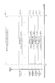
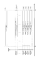
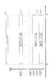
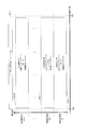
- FIG. 88 shows an example of the communication state of the wireless communication device described in Patent Document 1.
- the wireless communication device 001 transmits a sector sweep signal. After that, the wireless communication device 051 transmits a sector sweep signal. Then, the wireless communication device 051 transmits a signal including feedback information regarding the sector sweep to the wireless communication device 001.
- the wireless communication device 001 determines the method of "transmit beamforming and / or receive beamforming", and the wireless communication device 051 also determines "transmit beamforming and / or reception”. Determine the method of "beamforming".
- the communicable distance between the wireless communication device 001 and the wireless communication device 051 can be increased, but in an environment where a plurality of wireless communication devices exist, the entire system of the communication system composed of the plurality of wireless communication devices There remains a problem in improving the data transmission efficiency of.
- the non-limiting examples of the present disclosure contribute to the provision of a technique for improving the data transmission speed when a plurality of wireless communication devices are present.
- the wireless communication system includes a first wireless communication device that transmits a plurality of first reference signals whose directivity is controlled by an Orthogonal Frequency Division Multiple Access (OFDM) method in a first period.
- a plurality of second reference signals whose directivity is controlled and include information on the directivity corresponding to at least one of the first reference signals received from the first wireless communication device are used in the second period.
- a second wireless communication device for transmitting to the wireless communication device is provided.
- the wireless communication device receives a plurality of first reference signals whose directivity is controlled by another wireless communication device by the Orthogonal Frequency Division Multiple Access (OFDMA) method in the first period.
- OFDMA Orthogonal Frequency Division Multiple Access
- the wireless communication device includes a transmission processing unit that transmits a plurality of first reference signals whose directivity is controlled by an Orthogonal Frequency Division Multiple Access (OFDM) method in a first period, and the first. At least one of a plurality of second reference signals containing information on the directivity corresponding to any one of the reference signals and whose directivity is controlled by another wireless communication device that has received the first reference signal. , A reception processing unit for receiving in the second period.
- OFDM Orthogonal Frequency Division Multiple Access
- the first wireless communication device transmits a plurality of first reference signals whose directivity is controlled in the first period by the Orthogonal Frequency Division Multiple Access (OFDMA) method.
- the second wireless communication device includes information on the directivity corresponding to any one of the first reference signals received from the first wireless communication device, and a plurality of second reference signals whose directivity is controlled. , Transmission to the first wireless communication device in the second period.
- OFDMA Orthogonal Frequency Division Multiple Access
- the data transmission speed is improved when a plurality of wireless communication devices are present.
- FIG. 1A The figure which shows the configuration example different from FIG. 1A of the communication apparatus in Embodiment 1.
- FIG. The figure which shows the configuration example of the i-th transmitter 1A, 1B, 1C is a diagram showing an example of the configuration of the transmission panel antenna i.
- 1A, 1B, 1C is a diagram showing an example of the configuration of the receiving panel antenna i.
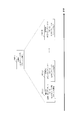
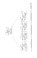
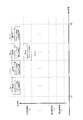
- FIG. 9 is a diagram showing an example of a sector sweep reference signal of FIG. 10 transmitted by base station # 1 of FIG.
- FIG. 11 is a diagram showing a configuration example of “reference signal for sector sweep in transmission panel antenna i for frequency ⁇ p”.
- FIG. 15A is a diagram showing a configuration example of “reference signal for sector sweep in terminal # i transmission panel antenna xi”.
- the figure which shows the example of the transmission situation of the modulation signal of the base station # 1 after FIG. The figure which shows the configuration example of the "frame containing a data symbol" transmitted by the terminal # 1.
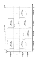
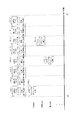
- FIG. 6 is a diagram showing an example of occupancy of a terminal in the transmission section of the “sector sweep reference signal” for the terminal shown in FIG. 13, which is different from FIG.
- FIG. 6 is a diagram showing an example of occupancy of a terminal in the transmission section of the “sector sweep reference signal” for the terminal shown in FIG. 13, which is different from FIG.
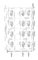
- FIG. 23 A diagram showing a configuration example of a "frame containing a data symbol" transmitted by terminals such as terminals # 1 to terminal # 6.
- FIG. 27 is a diagram showing a first example of the configuration of the feedback signal group transmitted by the base station # 1 existing in the time interval from t2 to t3 in FIG. 27.
- FIG. 27 is a diagram showing a first example of the configuration of the feedback signal group transmitted by the base station # 1 existing in the time interval from t2 to t3 in FIG. 27.
- FIG. 27 is a diagram showing a first example of the configuration of a frame group including a data symbol transmitted by base station # 1, which exists in the time interval from t4 to t5 in FIG. 27.
- FIG. 27 is a diagram showing a first example of the configuration of a frame group including a data symbol transmitted by base station # 1, which exists in the time interval from t4 to t5 in FIG. 27.
- FIG. 27 is a diagram showing a first example of the configuration of a frame group including a data symbol transmitted by base station # 1, which exists in the time interval from t4 to t5 in FIG. 27.
- FIG. 27 is a diagram showing a second example of the configuration of the feedback signal group transmitted by the base station # 1 existing in the time interval from t2 to t3 in FIG. 27.
- FIG. 27 is a diagram showing a second example of the configuration of the feedback signal group transmitted by the base station # 1 existing in the time interval from t2 to t3 in FIG. 27.
- FIG. 27 is a diagram showing a second example of the configuration of a frame group including a data symbol transmitted by base station # 1, which exists in the time interval from t4 to t5 in FIG. 27.
- FIG. 27 is a diagram showing a second example of the configuration of a frame group including a data symbol transmitted by base station # 1, which exists in the time interval from t4 to t5 in FIG. 27.
- FIG. 27 is a diagram showing a second example of the configuration of a frame group including a data symbol transmitted by base station # 1, which exists in the time interval from t4 to t5 in FIG. 27.
- FIG. 27 is a diagram showing a third example of the configuration of the feedback signal group transmitted by the base station # 1 existing in the time interval from t2 to t3 in FIG. 27.
- FIG. 27 is a diagram showing a third example of the configuration of the feedback signal group transmitted by the base station # 1 existing in the time interval from t2 to t3 in FIG. 27.
- FIG. 27 is a diagram showing a third example of the configuration of a frame group including a data symbol transmitted by base station # 1, which exists in the time interval from t4 to t5 in FIG. 27.
- FIG. 27 is a diagram showing a third example of the configuration of a frame group including a data symbol transmitted by base station # 1, which exists in the time interval from t4 to t5 in FIG. 27.
- FIG. 27 is a diagram showing a third example of the configuration of a frame group including a data symbol transmitted by base station # 1, which exists in the time interval from t4 to t5 in FIG. 27.
- FIG. 27 is a diagram showing a fourth example of the configuration of the feedback signal group transmitted by the base station # 1 existing in the time interval from t2 to t3 in FIG. 27.
- FIG. 27 is a diagram showing a fourth example of the configuration of the feedback signal group transmitted by the base station # 1 existing in the time interval from t2 to t3 in FIG. 27.
- FIG. 27 is a diagram showing a fourth example of the configuration of a frame group including a data symbol transmitted by base station # 1, which exists in the time interval from t4 to t5 in FIG. 27.
- FIG. 27 is a diagram showing a fourth example of the configuration of a frame group including a data symbol transmitted by base station # 1, which exists in the time interval from t4 to t5 in FIG. 27.
- FIG. 27 is a diagram showing a fourth example of the configuration of a frame group including a data symbol transmitted by base station # 1, which exists in the time interval from t4 to t5 in FIG. 27.
- FIG. 27 is a diagram showing a fifth example of the configuration of the feedback signal group transmitted by the base station # 1 existing in the time interval from t2 to t3 in FIG. 27.
- FIG. 27 is a diagram showing a fifth example of the configuration of a frame group including a data symbol transmitted by base station # 1, which exists in the time interval from t4 to t5 in FIG. 27.
- FIG. 27 is a diagram showing a sixth example of the configuration of the feedback signal group transmitted by the base station # 1 existing in the time interval from t2 to t3 in FIG. 27.
- FIG. 27 is a diagram showing a sixth example of the configuration of a frame group including a data symbol transmitted by base station # 1, which exists in the time interval from t4 to t5 in FIG. 27.
- FIG. 27 is a diagram showing a seventh example of the configuration of the feedback signal group transmitted by the base station # 1 existing in the time interval from t2 to t3 in FIG. 27.
- FIG. 27 is a diagram showing a seventh example of the configuration of a frame group including a data symbol transmitted by base station # 1, which exists in the time interval from t4 to t5 in FIG. 27.
- FIG. 9 is a diagram showing an example of a situation when base station # 1 and "terminal such as terminal # 1" are communicating with each other.
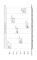
- FIG. 42 is a diagram showing an example of the transmission status of the modulated signal of the base station # 1 and the transmission status of the modulated signal of the “terminal such as terminal # 1” after FIG. 42.
- FIG. 14 is a diagram showing an example of the configuration of the terminal # i “reference signal for sector sweep” in FIG.
- the figure which shows an example of the structure of the reference signal for sector sweep of FIG. The figure which shows the operation example of the time interval from time t1 to t2 which is a terminal response interval.
- FIG. 59A The figure which shows the configuration example of the "frame containing a data symbol" transmitted by the terminal # 3.
- FIG. 59B The figure which shows the example about the occupation of the terminal in the "sector sweep reference signal" for the terminal shown in FIG. 59A, which is different from FIG. 59B.
- FIG. 27 is a diagram showing an eighth example of the configuration of the feedback signal group transmitted by the base station # 1 existing in the time interval from t2 to t3 in FIG. 27.
- FIG. 27 is a diagram showing an eighth example of the configuration of the feedback signal group transmitted by the base station # 1 existing in the time interval from t2 to t3 in FIG. 27.
- FIG. 27 is a diagram showing an eighth example of the configuration of a frame group including a data symbol transmitted by base station # 1, which exists in the time interval from t4 to t5 in FIG. 27.
- FIG. 27 is a diagram showing an eighth example of the configuration of a frame group including a data symbol transmitted by base station # 1, which exists in the time interval from t4 to t5 in FIG. 27.
- FIG. 27 is a diagram showing an eighth example of the configuration of a frame group including a data symbol transmitted by base station # 1, which exists in the time interval from t4 to t5 in FIG. 27.
- FIG. 27 is a diagram showing a ninth example of the configuration of the feedback signal group transmitted by the base station # 1 existing in the time interval from t2 to t3 in FIG. 27.
- FIG. 27 is a diagram showing a ninth example of the configuration of the feedback signal group transmitted by the base station # 1 existing in the time interval from t2 to t3 in FIG. 27.
- FIG. 27 is a diagram showing a ninth example of the configuration of a frame group including a data symbol transmitted by base station # 1 existing in the time interval from t4 to t5 in FIG. 27.
- FIG. 27 is a diagram showing a ninth example of the configuration of a frame group including a data symbol transmitted by base station # 1 existing in the time interval from t4 to t5 in FIG. 27.
- FIG. 27 is a diagram showing a ninth example of the configuration of a frame group including a data symbol transmitted by base station # 1 existing in the time interval from t4 to t5 in FIG. 27.
- FIG. 27 is a diagram showing a tenth example of the configuration of the feedback signal group transmitted by the base station # 1 existing in the time interval from t2 to t3 in FIG. 27.
- FIG. 27 is a diagram showing a tenth example of the configuration of a frame group including a data symbol transmitted by base station # 1, which exists in the time interval from t4 to t5 in FIG. 27.
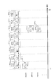
- FIG. 9 is a diagram showing an example of a sector sweep reference signal of FIG. 10 transmitted by base station # 1 of FIG.
- FIG. 73 is a diagram showing a configuration example of “reference signal for sector sweep in transmission panel antenna X for frequency $ X”.
- FIG. 74 is a diagram showing a configuration example of “reference signal for sector sweep in transmission panel antenna X for frequency $ X_i”.
- FIG. 78A is a diagram showing a configuration example of a feedback signal transmission section in the transmission panel antenna X for frequency $ X of FIG. 78A.
- FIG. 79A is a diagram showing a configuration example of a transmission section of a modulated signal (slot) in the transmission panel antenna X for frequency $ X of FIG. 79A.
- FIG. 77A The figure which shows the example about the occupation of the terminal in the transmission section of the "sector sweep reference signal" for a terminal shown in FIG. 13, which is different from FIG. 77A.
- FIG. 58 The figure which shows the example of the structure in time and frequency of the "reference signal for sector sweep” for a terminal shown in FIG. 58.
- FIG. 83A The figure which shows the example about the occupation of the terminal in the "reference signal for sector sweep” for the terminal shown in FIG. 83A.
- FIG. 84A is a diagram showing a configuration example of “feedback signal in transmission panel antenna X for frequency $ X”.
- FIG. 85A is a diagram showing a configuration example of the “modulated signal (slot) in the transmission panel antenna X for frequency $ X”.
- FIG. 8 is a diagram showing an example of occupancy of a terminal in the “sector sweep reference signal” for a terminal shown in FIG. 58, which is different from FIG. 82B.
- FIG. 8 is a diagram showing an example of occupancy of a terminal in the “sector sweep reference signal” for a terminal shown in FIG. 58, which is different from FIG. 82B.
- FIG. 1A shows an example of the configuration of a communication device such as a base station, an access point, a terminal, and a repeater in the first embodiment.
- the communication device of FIG. 1A shall include N transmission units of "first transmission unit 102_1 to Nth transmission unit 102_N".
- N is an integer of 1 or more or an integer of 2 or more.
- the communication device of FIG. 1A shall be provided with M transmission panel antennas for "transmission panel antennas 1 to 106_M transmission panel antennas M of 106_1".
- M is an integer of 1 or more or an integer of 2 or more.
- the communication device of FIG. 1A shall include n receiving units of "first receiving unit 155_1 to nth receiving unit 155_n".
- n is an integer of 1 or more or an integer of 2 or more.
- the communication device of FIG. 1A shall be provided with m receiving panel antennas for receiving "the receiving panel antennas 1 to 151_m of 151_1".
- m is an integer of 1 or more or an integer of 2 or more.
- the i-th transmission unit 102_i receives the control signal 100 and the i-th data 101_i as inputs, performs processing such as error correction coding and mapping by a modulation method, and outputs the i-modulation signal 103_i. It is assumed that i is an integer of 1 or more and N or less.
- the i-th data 101_i may be configured to include data of one or more users.
- the error correction code, modulation method, and transmission method may be set for each user.
- the first processing unit 104 inputs the i-modulated signal 103_i (i is an integer of 1 or more and N or less), the control signal 100, and the reference signal 199, and the first j is based on the information of the frame configuration included in the control signal 100.
- the transmission signal 105_j (j is an integer of 1 or more and M or less) is output. It should be noted that some of the i-modulated signals 103_i may not have a signal, and some of the j-th transmission signals 105_j may have no signal.
- the jth transmission signal 105_j is output as a radio wave from the transmission panel antenna j of 106_j.
- the transmission panel antenna j of 106_j may receive the control signal 100 as an input, perform beamforming, and change the transmission directivity. Further, the transmission panel antenna j of 106_j may be switched when the modulation signal is transmitted to the communication partner by the control signal 100. This point will be described later.
- the i-th reception signal 152_i is received by the reception panel antenna i of 151_i.
- the receiving panel antenna i of 151_i may receive the control signal 100 as an input, perform beamforming, and change the receiving directivity. This point will be described later.
- the second processing unit 153 receives the i-received signal 152_i and the control signal 100 as inputs, performs processing such as frequency conversion, and outputs the signal 154_j after the jth signal processing. It should be noted that some of the i-th received signals 152_i may have no signal, and some of the j-th signal processed signals 154_j do not have a signal. You may.
- the j-th receiving unit 155_j receives the signal 154_j after the jth signal processing and the control signal 100 as inputs, and demodulates, corrects and decodes the error, etc. with respect to the signal 154_j after the jth signal processing based on the control signal 100. Processing is performed, and the jth control data 156_j and the jth data 157_j are output.
- the jth control data 156_j may be configured to include control data of one or more users. Further, the j-th data 157_j may be configured to include data of one or more users.
- the third processing unit 158 takes the jth control data 156_j as an input, generates a control signal 100 based on the information obtained from the communication partner, and outputs the control signal 100.
- the first processing unit 104 of the communication device of FIG. 1A may perform processing for transmission beamforming (transmission directivity control), for example, precoding processing.
- the second processing unit 153 may perform processing for receiving directivity control.
- the first processing unit 104 uses the first transmission signal 105_1 as the first modulation signal 103_1, the second transmission signal 105_2 as the second modulation signal 103_2, and the third transmission signal 105___ as the third modulation signal. You may perform processing such as setting it to 103_3 and outputting it.
- the first processing unit 104 may perform processing such that the first transmission signal 105_1 is used as the second modulation signal 103_2 and is output.
- the second processing unit 153 sets the signal 154_1 after the first signal processing as the first reception signal 152_1, the signal 154_2 after the second signal processing as the second reception signal 152_2, and after the third signal processing.
- the signal 154_3 may be set as the third received signal 152_3, and processing may be performed to output the signal 154_3.
- the second processing unit 153 may perform processing such that the signal 154_2 after the second signal processing is output as the first reception signal 152_1.
- the communication device may include an interleaver for rearranging symbols and / or data, a padding unit for padding, and the like.
- the communication device of FIG. 1A corresponds to MIMO (Multiple Input Multiple Output) transmission in which a plurality of modulated signals (multiple streams) are transmitted by using a plurality of antennas. Alternatively, reception may be performed.
- the communication device of FIG. 1A (and FIGS. 1B and 1C) is a multi-user that transmits a modulated signal to a plurality of terminals at least in a first time interval using a first frequency (band). Transmission corresponding to MIMO transmission may be performed.
- FIG. 1B is a configuration example different from FIG. 1A of a communication device such as a base station, an access point, a terminal, and a repeater in the first embodiment.
- a communication device such as a base station, an access point, a terminal, and a repeater in the first embodiment.
- FIG. 1B those operating in the same manner as in FIG. 1A are assigned the same number, and detailed description thereof will be omitted.
- the characteristic point of FIG. 1B is that the number of transmitting units and the number of transmitting panel antennas are the same.
- the first processing unit 104 may perform processing for transmission beamforming (transmission directivity control), for example, precoding. Further, the first processing unit 104 may output the xth transmission signal 105_x as the y-modulation signal 103_y. It is assumed that x is an integer of 1 or more and M or less, and y is an integer of 1 or more and M or less.
- the second processing unit 153 may perform processing for receiving directivity control. Further, the second processing unit 153 may output the signal 154_x after the processing of the xth signal as the y-th received signal 152_y. It is assumed that x is an integer of 1 or more and m or less, and y is an integer of 1 or more and m or less.
- FIG. 1C is a configuration example different from FIGS. 1A and 1B of a communication device such as a base station, an access point, a terminal, and a repeater in the first embodiment.
- a communication device such as a base station, an access point, a terminal, and a repeater in the first embodiment.
- the same numbers are assigned to those operating in the same manner as in FIG. 1A, and detailed description thereof will be omitted.
- the characteristic point of FIG. 1C is that the number of transmitting units and the number of transmitting panel antennas are the same, and the first processing unit does not exist. Further, the number of receiving units and the number of receiving panel antennas are the same, and the second processing unit does not exist.
- FIGS. 1A, 1B, and 1C are examples of configurations of communication devices such as base stations, access points, terminals, and repeaters, and the method of configuring communication devices is not limited to this example.
- FIG. 2 shows a configuration example of the i-th transmission unit 102_i.
- i is "an integer of 1 or more and N or less" or "an integer of 1 or more and M or less”.
- the data symbol generation unit 202 receives the data 201 and the control signal 200 as inputs, and uses the control signal 200 for information such as error correction coding method information, modulation method information, transmission method information, and frame configuration method. Based on this, error correction coding, mapping, signal processing for transmission, and the like are performed, and the modulated signal 203 of the data symbol is output.
- the data 201 corresponds to the i-th data 101_i
- the control signal 200 corresponds to the control signal 100. Therefore, the data 201 may include data of one or more users.
- the sector sweep reference signal generation unit 204 receives the control signal 200 as an input, and generates and outputs the sector sweep reference signal 205 based on the frame configuration information included in the control signal 200.
- the specific configuration method and transmission method of the sector sweep reference signal 205 will be described in detail later.
- the other signal generation unit 206 receives the control signal 200 as an input, and generates and outputs the other signal 207 based on the control signal.
- the processing unit 251 inputs the modulation signal 203 of the data symbol, the reference signal 205 for sector sweep, the other signal 207, and the control signal 200, and modulates according to the frame configuration based on the information of the frame configuration included in the control signal 200. Generates and outputs signal 252.
- the modulation signal 252 according to the frame configuration corresponds to the i-th modulation signal 103_i. A specific example of the frame configuration will be described in detail later.
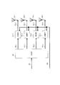
- FIG. 3 shows an example of the configuration of the transmission panel antenna i of 106_i in FIGS. 1A, 1B, and 1C. It is assumed that i is an "integer of 1 or more and M or less".
- the distribution unit 302 takes the transmission signal 301 as an input, distributes the signal, and outputs the first transmission signal 303_1, the second transmission signal 303_2, the third transmission signal 303_3, and the fourth transmission signal 303_4.
- the transmission signal 301 corresponds to "the i-th transmission signal 105_i in FIGS. 1A and 1B" or "the i-modulation signal 103_i in FIG. 1C".
- the multiplication unit 304_1 takes the first transmission signal 303_1 and the control signal 300 as inputs, multiplies the first transmission signal 303_1 by a multiplication coefficient based on the control signal 300, and generates the first transmission signal 305_1 after the coefficient multiplication. ,Output. Then, the first transmission signal 305_1 after the coefficient multiplication is output as a radio wave from the antenna 306_1.
- the control signal 300 corresponds to the control signal 100.
- the first transmission signal 303_1 is represented as tx1 (t). It is assumed that t is time. Then, assuming that the multiplication coefficient is w1, the first transmission signal 305_1 after the coefficient multiplication can be represented as tx1 (t) ⁇ w1. It should be noted that tx1 (t) can be represented by a complex number, and therefore may be a real number. Further, w1 can be represented by a complex number, and therefore may be a real number.
- the multiplication unit 304_2 takes the second transmission signal 303_2 and the control signal 300 as inputs, multiplies the second transmission signal 303_2 by the multiplication coefficient based on the control signal 300, and generates the second transmission signal 305_2 after the coefficient multiplication. ,Output. Then, the second transmission signal 305_2 after the coefficient multiplication is output as a radio wave from the antenna 306_2.
- the second transmission signal 303_2 is represented as tx2 (t). It is assumed that t is time. Then, assuming that the multiplication coefficient is w2, the second transmission signal 305_2 after the coefficient multiplication can be represented as tx2 (t) ⁇ w2. It should be noted that tx2 (t) can be represented by a complex number, and therefore may be a real number. Further, w2 can be represented by a complex number, and therefore may be a real number.
- the multiplication unit 304_3 takes the third transmission signal 303_3 and the control signal 300 as inputs, multiplies the third transmission signal 303_3 by the multiplication coefficient based on the control signal 300, and generates the third transmission signal 305_3 after the coefficient multiplication. ,Output. Then, the third transmission signal 305_3 after the coefficient multiplication is output as a radio wave from the antenna 306_3.
- the third transmission signal 303_3 shall be represented as tx3 (t). It is assumed that t is time. Then, assuming that the multiplication coefficient is w3, the third transmission signal 305_3 after the coefficient multiplication can be represented as tx3 (t) ⁇ w3. It should be noted that tx3 (t) can be represented by a complex number, and therefore may be a real number. Further, w3 can be represented by a complex number, and therefore may be a real number.
- the multiplication unit 304_4 takes the fourth transmission signal 303_4 and the control signal 300 as inputs, multiplies the fourth transmission signal 303_4 by the multiplication coefficient based on the control signal 300, and generates the fourth transmission signal 305_4 after the coefficient multiplication. ,Output. Then, the fourth transmission signal 305_4 after the coefficient multiplication is output as a radio wave from the antenna 306_4.
- the fourth transmission signal 303_4 is represented as tx4 (t). It is assumed that t is time. Then, assuming that the multiplication coefficient is w4, the fourth transmission signal 305_4 after the coefficient multiplication can be represented as tx4 (t) ⁇ w4. It should be noted that tx4 (t) can be represented by a complex number, and therefore may be a real number. Further, w4 can be represented by a complex number, and therefore may be a real number.
- the absolute value of w1, the absolute value of w2, the absolute value of w3, and the absolute value of w4 are equal may be used. At this time, it corresponds to the phase change being performed. As a matter of course, the absolute value of w1, the absolute value of w2, the absolute value of w3, and the absolute value of w4 do not have to be equal.
- the values of w1, w2, w3, and w4 may be switched for each frame, for each slot, for each mini-slot, or for each of a plurality of symbols. It may be switched for each symbol.
- the switching timing of each of the values of w1, w2, w3, and w4 is not limited to the above example.
- the transmission panel antenna of FIG. 3 is described with an example of being composed of four antennas (and four multiplication units), the number of antennas is not limited to four, and two or more antennas are used. It suffices if it is composed of the antenna of.
- the transmission panel antenna i of 106_i in FIGS. 1A, 1B, and 1C may perform directivity control by changing the characteristics of the antenna itself. At this time, the transmission panel antenna i of 106_i is 1 or more. It suffices if it is composed of the antenna of.
- FIG. 4 shows an example of the configuration of the receiving panel antenna i of 151_i in FIGS. 1A, 1B, and 1C. It is assumed that i is an "integer of 1 or more and m or less".
- the multiplication unit 403_1 takes the first reception signal 402_1 and the control signal 400 received by the antenna 401_1 as inputs, multiplies the first reception signal 402_1 by the multiplication coefficient based on the control signal 400, and the first reception after the coefficient multiplication.
- the signal 404_1 is output.
- the first received signal 402_1 is represented as rx1 (t). It is assumed that t is time. Then, assuming that the multiplication coefficient is d1, the first received signal 404_1 after the coefficient multiplication can be represented as rx1 (t) ⁇ d1. It should be noted that rx1 (t) can be represented by a complex number, and therefore may be a real number. Further, d1 can be represented by a complex number, and therefore may be a real number.
- the multiplication unit 403_2 takes the second reception signal 402_2 and the control signal 400 received by the antenna 401_2 as inputs, multiplies the second reception signal 402_2 by the multiplication coefficient based on the control signal 400, and the second reception after the coefficient multiplication.
- the signal 404_2 is output.
- the second received signal 402_2 is represented as rx2 (t). It is assumed that t is time. Then, assuming that the multiplication coefficient is d2, the second received signal 404_2 after the coefficient multiplication can be represented as rx2 (t) ⁇ d2. It should be noted that rx2 (t) can be represented by a complex number, and therefore may be a real number. Further, d2 can be represented by a complex number, and therefore may be a real number.
- the multiplication unit 403_3 takes the third reception signal 402_3 and the control signal 400 received by the antenna 401_3 as inputs, multiplies the third reception signal 402_3 by the multiplication coefficient based on the control signal 400, and the third reception after the coefficient multiplication.
- the signal 404_3 is output.
- the third received signal 402_3 is represented as rx3 (t). It is assumed that t is time. Then, assuming that the multiplication coefficient is d3, the third received signal 404_3 after the coefficient multiplication can be represented as rx3 (t) ⁇ d3. Note that rx3 (t) can be represented by a complex number, and therefore may be a real number. Further, d3 can be represented by a complex number, and therefore may be a real number.
- the multiplication unit 403_4 takes the fourth received signal 402_4 and the control signal 400 received by the antenna 401_4 as inputs, multiplies the fourth received signal 402_4 by the multiplication coefficient based on the control signal 400, and the fourth reception after the coefficient multiplication.
- the signal 404_4 is output.
- the fourth received signal 402_4 is represented as rx4 (t). It is assumed that t is time. Then, assuming that the multiplication coefficient is d4, the fourth received signal 404_4 after the coefficient multiplication can be represented as rx4 (t) ⁇ d4. It should be noted that rx4 (t) can be represented by a complex number, and therefore may be a real number. Further, d4 can be represented by a complex number, and therefore may be a real number.
- the coupling unit / synthesis unit 405 receives the first received signal 404_1 after the coefficient multiplication, the second received signal 404_2 after the coefficient multiplication, the third received signal 404_3 after the coefficient multiplication, and the fourth received signal 404_4 after the coefficient multiplication.
- the first received signal 404_1 after coefficient multiplication, the second received signal 404_2 after coefficient multiplication, the third received signal 404_3 after coefficient multiplication, and the fourth received signal 404_4 after coefficient multiplication are combined, and the modulated signal 406 is output. ..
- the modulated signal 406 is represented as rx1 (t) ⁇ d1 + rx2 (t) ⁇ d2 + rx3 (t) ⁇ d3 + rx4 (t) ⁇ d4.
- the control signal 400 corresponds to the control signal 100.
- the modulated signal 406 corresponds to the i-th received signal of 152_i.
- the absolute value of d1, the absolute value of d2, the absolute value of d3, and the absolute value of d4 may be used. At this time, it corresponds to the phase change being performed. As a matter of course, the absolute value of d1, the absolute value of d2, the absolute value of d3, and the absolute value of d4 do not have to be equal.
- the values of d1, d2, d3, and d4 may be switched for each frame, for each slot, for each mini slot, or for each of a plurality of symbols. It may be switched for each symbol.
- the switching timing of each of the values of d1, d2, d3, and d4 is not limited to the above example.
- the receiving panel antenna of FIG. 4 is described with an example of being composed of four antennas (and four multiplication units), the number of antennas is not limited to four, and two or more antennas are used. It suffices if it is composed of the antenna of.
- the receiving panel antenna i of 151_i in FIGS. 1A, 1B, and 1C may perform directivity control by changing the characteristics of the antenna itself.
- the receiving panel antenna i of 151_i is 1 or more. It suffices if it is composed of the antenna of.
- FIGS. 1A, 1B, and 1C are, for example, a base station, gNB (g Node).
- gNB g Node
- the transmission of multi-carrier transmission such as an OFDM (Orthogonal Frequency Division Multiplexing) transmission method is supported.
- the base station and gNB of FIGS. 1A, 1B, and 1C may correspond to OFDMA (Orthogonal Frequency Division Multiple Access).
- FIG. 5 shows a configuration example of a transmission device when the OFDM method is used.
- the transmission device is composed of a constellation mapper 501, a serial-parallel transform unit 502, and an IFFT (Inverse Fast Fourier Transform) 503.
- IFFT Inverse Fast Fourier Transform
- the constellation mapper 501 takes data as an input, performs mapping based on a set modulation method, and outputs a modulation signal.
- the serial / parallel conversion unit 502 changes the serial signal to a parallel signal. If a parallel signal has already been obtained, the serial-parallel conversion unit 502 may not exist.
- the IFFT503 performs IFFT processing on the input signal and outputs a modulated signal based on the OFDM method.
- the IFFT 503 may be an inverse Fourier transform unit that performs an inverse Fourier transform.
- the transmitter when the OFDM method is used may have other processing units such as an error correction coding unit and an interleaver in the transmitter, and the configuration is not limited to that shown in FIG. ..
- FIGS. 1A, 1B, and 1C may correspond to reception of multi-carrier transmission such as, for example, in the case of a communication device of a base station or gNB, for example, an OFDM transmission method.
- a single carrier system such as a single carrier system based on DFT (Discrete Fourier Transform) may be supported.
- DFT Discrete Fourier Transform
- FIG. 6 shows a configuration example of the receiving device when the OFDM method is used.
- the receiving device when the OFDM method is used is a receiving FE processing unit (Rx (Receiver) FE (Front End) processing) 601, FFT (Fast Fourier Transform) 602, and a parallel serial transform unit 603.
- the receiver is configured with a Demapper 604.
- the receiving FE processing unit (RxFE processing) 601 processes the receiving front end.
- the FFT602 will perform FFT processing on the input signal.
- the parallel / serial conversion unit 603 converts the parallel signal into a serial signal. If the serial signal has already been obtained, the parallel / serial conversion unit 603 may not exist.
- Demapper 604 will perform demodulation processing based on the transmission method and modulation method.
- the receiving device may be provided with other processing units such as a deinterleaver and an error correction code decoding unit, and is not limited to the configuration shown in FIG.
- FIG. 7 shows a configuration example of the receiving device when the single carrier method based on DFT is used.
- the receiving FE processing unit Rx (Receiver) FE processing
- CP removal unit CP Removal
- FFT Fast Fourier Transform
- tone demapping Tone demoapping
- FDE Frequency
- the receiving device is composed of Domain Equalization) 705, DFT706, and Demapper 707.
- other processing units may exist in the receiving device.
- FIG. 8 shows a configuration example of the receiving device when the single carrier method based on the time domain is used.
- the receiving FE processing unit Rx (Receiver) FE processing
- the down-sampling and match filtering Down-sampling and match filtering
- the TDE Time Domain Equalization
- the CP removal unit CP Removal
- Demapper 805 the receiving device is composed of.
- other processing units may exist in the receiving device.
- the examples of the single carrier type receiving method and the configuration of the receiving device have been described, but the examples of the single carrier type receiving method and the receiving device are not limited to these.
- DFT-S OFDM Discrete Fourier Transform
- TFT-S OFDM Time-domain implementation single carrier method
- SC Single Carrier
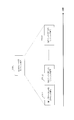
- FIG. 9 shows an example of the communication state in the first embodiment.
- the base station # 1 of 901_1 is the terminal # 1 of 902_1, the terminal # 2 of 902_2, the terminal # 3 of 902_3, the terminal # 4 of 902_4, the terminal # 5 of 902_5, and the terminal # 6 of 902_6.
- the base station and the terminal is not limited to this example, and for example, the base station may communicate with one or more terminals.
- the base station uses the OFDMA method to transmit a modulated signal to the terminal.
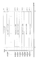
- FIG. 10 shows an example of a modulation signal 1000 transmitted by base station # 1 of 901_1 in FIG.
- the horizontal axis is time and the vertical axis is frequency.
- a reference signal 1001 for a sector sweep (sector sweep) exists in the time interval from time t0 to t1.
- the sector sweep reference signal 1001 will be described later.
- the time section from time t1 to t2 is the terminal response section.
- the response of the terminal will be described later.
- the feedback signal 1002 exists in the time interval from time t2 to t3.
- the feedback signal 1002 will be described later.
- the reference signal 1001 for sector sweep is named, but the name is not limited to this, and may be called a reference signal, a reference symbol, a training signal, a training symbol, a reference signal, a reference symbol, or the like.
- the name is given as the feedback signal 1002, the name is not limited to this, and may be referred to as a feedback symbol, a signal addressed to the terminal, a symbol addressed to the terminal, a control signal, a control symbol, or the like.
- the frame 1003 including the data symbol is named, but the name is not limited to this, and it may be called a frame including a slot, a mini slot, a unit, and the like.
- FIG. 11 shows an example of the sector sweep reference signal 1001 of FIG. 10 transmitted by the base station # 1 of FIG. 9 having the configurations of FIGS. 1A, 1B, and 1C, for example.
- the horizontal axis is time and the vertical axis is frequency.
- the base station # 1 of 901_1 since the base station # 1 of 901_1 transmits a modulated signal based on OFDMA, as shown in FIG. 11, the frequency band ⁇ 1, the frequency band ⁇ 2, ..., The frequency band ⁇ K It shall be divided.
- K is an integer of 1 or more or an integer of 2 or more.
- OFDM (A) it is assumed that one frequency band contains one or more (sub) carriers or contains two or more (sub) carriers. .. This point may be the same in other drawings and other embodiments.
- the sector sweep reference signal 1101_i1 in the frequency ⁇ i transmission panel antenna 1 in the first time section and the sector sweep reference signal 1101_i2 in the frequency ⁇ i transmission panel antenna 2 in the second time section.
- the sector sweep reference signal 1101_iM in the frequency ⁇ i transmission panel antenna M exists in the Mth time section.
- i is an integer of 1 or more and K or less.
- the sector sweep reference signal 1101_ij in the frequency ⁇ i transmission panel antenna j is transmitted from the transmission panel antenna j of 106_j of the base station # 1 of 901_1 having the configurations of FIGS. 1A, 1B, and 1C. Become. At this time, j is an integer of 1 or more and M or less.
- the sector sweep reference signal is transmitted from the same transmission panel antenna regardless of the frequency band.
- the same beamforming parameters are used in the first time zone regardless of the frequency band. Beamforming will be described later.
- FIG. 12 shows a configuration example of the “reference signal 1101_pi for sector sweep in the transmission panel antenna i for frequency ⁇ p” of FIG.
- the horizontal axis is time. It is assumed that p is an integer of 1 or more and K or less, and i is an integer of 1 or more and M or less.
- the base station # 1 of 901_1 having the configurations of FIGS. 1A, 1B, and 1C has the configuration of FIG. 3 as the transmission panel antenna i of 106_i.
- the “reference signal 1201_1 according to the first parameter in the transmission panel antenna i for frequency ⁇ p" will be described.
- the base station # 1 of 901_1 transmits the “reference signal 1201_1 according to the first parameter in the transmission panel antenna i for frequency ⁇ p” shown in FIG. 12, the base station # 1 of 901_1 is multiplied by the transmission panel antenna i of 106_i.
- the multiplication coefficient in unit 304_1 is set to w1 (i, 1).
- the multiplication unit 304_1 converts tx1ref1 (t) ⁇ w1 (i, 1). obtain.
- the base station # 1 of 901_1 transmits tx1ref1 (t) ⁇ w1 (i, 1) from the antenna 306_1 of FIG.
- t is time.
- the base station # 1 of 901_1 transmits the “reference signal 1201_1 according to the first parameter in the transmission panel antenna i for frequency ⁇ p” shown in FIG. 12, the base station # 1 of 901_1 is multiplied by the transmission panel antenna i of 106_i.
- the multiplication coefficient in unit 304_2 is set to w2 (i, 1).
- the multiplication unit 304_2 sets tx2ref1 (t) ⁇ w2 (i, 1). obtain.
- the base station # 1 of 901_1 transmits tx2ref1 (t) ⁇ w2 (i, 1) from the antenna 306_2 of FIG.
- the base station # 1 of 901_1 transmits the “reference signal 1201_1 according to the first parameter in the transmission panel antenna i for frequency ⁇ p” shown in FIG. 12, the base station # 1 of 901_1 is multiplied by the transmission panel antenna i of 106_i.
- the multiplication coefficient in unit 304_3 is set to w3 (i, 1).
- the multiplication unit 304_3 converts tx3ref1 (t) ⁇ w3 (i, 1). obtain.
- the base station # 1 of 901_1 transmits tx3ref1 (t) ⁇ w3 (i, 1) from the antenna 306_3 of FIG.
- the base station # 1 of 901_1 transmits the “reference signal 1201_1 according to the first parameter in the transmission panel antenna i for frequency ⁇ p” shown in FIG. 12, the base station # 1 of 901_1 is multiplied by the transmission panel antenna i of 106_i.
- the multiplication coefficient in unit 304_4 is set to w4 (i, 1).
- the fourth transmission signal 303_4 in the "reference signal 1201_1 by the first parameter in the transmission panel antenna i for frequency ⁇ p" is tx4ref1 (t)
- the multiplication unit 304_4 sets tx4ref1 (t) x w4 (i, 1). obtain.
- the base station # 1 of 901_1 transmits tx4ref1 (t) ⁇ w4 (i, 1) from the antenna 306_4 of FIG.
- the base station # 1 of 901_1 transmits the “reference signal 1201_j by the j parameter in the transmission panel antenna i for frequency ⁇ p” shown in FIG. 12, the base station # 1 of 901_1 is multiplied by the transmission panel antenna i of 106_i.
- the multiplication coefficient in unit 304_1 is set to w1 (i, j).
- the multiplication unit 304_1 sets tx1refj (t) ⁇ w1 (i, j). obtain.
- the base station # 1 of 901_1 transmits tx1refj (t) ⁇ w1 (i, j) from the antenna 306_1 of FIG.
- t is time.
- the base station # 1 of 901_1 transmits the “reference signal 1201_j by the j parameter in the transmission panel antenna i for frequency ⁇ p” shown in FIG. 12, the base station # 1 of 901_1 is multiplied by the transmission panel antenna i of 106_i.
- the multiplication coefficient in unit 304_2 is set to w2 (i, j).
- the multiplication unit 304_2 sets tx2refj (t) ⁇ w2 (i, j). obtain.
- the base station # 1 of 901_1 transmits tx2refj (t) ⁇ w2 (i, j) from the antenna 306_2 of FIG.
- the base station # 1 of 901_1 transmits the “reference signal 1201_j by the j parameter in the transmission panel antenna i for frequency ⁇ p” shown in FIG. 12, the base station # 1 of 901_1 is multiplied by the transmission panel antenna i of 106_i.
- the multiplication coefficient in unit 304_3 is set to w3 (i, j).
- the multiplication unit 304_3 sets tx3refj (t) ⁇ w3 (i, j). obtain.
- the base station # 1 of 901_1 transmits tx3refj (t) ⁇ w3 (i, j) from the antenna 306_3 of FIG.
- the base station # 1 of 901_1 transmits the “reference signal 1201_j by the j parameter in the transmission panel antenna i for frequency ⁇ p” shown in FIG. 12, the base station # 1 of 901_1 is multiplied by the transmission panel antenna i of 106_i.
- the multiplication coefficient in unit 304_4 is set to w4 (i, j).
- the fourth transmission signal 303_4 in the "reference signal 1201_j by the j parameter in the transmission panel antenna i for frequency ⁇ p" is tx4refj (t)
- the multiplication unit 304_4 sets tx4refj (t) ⁇ w4 (i, j). obtain.
- the base station # 1 of 901_1 transmits tx4refj (t) ⁇ w4 (i, j) from the antenna 306_4 of FIG.
- j is an integer of 1 or more and 4 or less.
- j is an integer greater than or equal to 1 and less than or equal to Z.
- the “reference signal 1101_i for sector sweep in the transmission panel antenna i for frequency ⁇ p” is transmitted.
- the "reference signal 1201_j by the j parameter” includes, for example, the following information. -ID (identification) (identification number) of the transmitting panel antenna (here, for example, equivalent to i) -Identification number (ID) of the parameter used in beamforming (directivity control) (here, for example, corresponds to j).
- -ID identification number
- ID Identification number of the parameter used in beamforming (directivity control)
- the "reference signal 1201_j according to the jth parameter in the transmission panel antenna i for frequency ⁇ p" may include the following information. -Information on the frequency band and / or frequency ⁇ p (information on the number of divisions of the frequency may be included) (Note that this point will be described later.)
- Base station # 1 of 901_1 transmits "ID (identification) (identification number) of transmission panel antenna for frequency ⁇ p" and “identification number (ID) of parameters used in beamforming (directivity control)". Then, the terminal can know the “identification (identification number) of the transmitting panel antenna” and the “identification number (ID) of the parameter used in beamforming (directivity control)” that could be received. , 901_1 base station # 1 and the terminal can perform appropriate control, which can obtain the effect of improving the data reception quality.
- the "number of time divisions in which the reference signal for sector sweep can be transmitted when the terminal transmits the reference signal for sector sweep" may be changed depending on the frame and / or time. This has the effect of improving the data transmission efficiency of the communication system.
- the base station # 1 of 901_1 transmits "information on the frequency band and / or the frequency ⁇ p", so that the terminal obtains this information and "information related to the frequency to be transmitted to the base station".
- the base station can perform appropriate control and can obtain the effect of improving the reception quality of data.
- the terminal uses OFDM, and the frequency (band) used by the base station and the frequency (band) used by the terminal partially have the same frequency (band). The case will be described as an example.
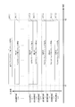
- FIG. 13 shows an operation example of a time section from time t1 to t2, which is a terminal response section.
- the horizontal axis is time.
- Terminals such as 902_1 terminal # 1, 902_2 terminal # 2, 902_3 terminal # 3, 902_4 terminal # 4, 902_5 terminal # 5, and 902_6 terminal # 6 in FIG. 9 are terminal response sections at time t1.
- the sector sweep reference signal is transmitted in the time interval from t2 to t2.
- base station # 1 of 901_1 transmits a sector sweep reference signal in the time interval from time t0 to t1.
- the terminal response section which is the time section from time t1 to t2
- the first transmission section 1301_1 of the “sector sweep reference signal” for the terminal and the second transmission of the “sector sweep reference signal” for the terminal It is assumed that a section 1301_2, a "sector sweep reference signal” third transmission section 1301_3 for terminals, and a “sector sweep reference signal” fourth transmission section 1301_4 for terminals exist.
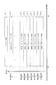
- FIG. 14 shows a terminal “sector sweep reference signal” first transmission section 1301_1, a terminal “sector sweep reference signal” second transmission section 1301_2, and a terminal “sector sweep reference signal” third.
- An example relating to the occupation of the terminal in the transmission section 1301_3 and the fourth transmission section 1301_4 of the "reference signal for sector sweep" for the terminal is shown.
- the horizontal axis is time and the vertical axis is frequency.
- Terminal # 1 of 902_1 in FIG. 9 receives the sector sweep reference signal 1001 transmitted by base station # 1 of 901_1, and among the transmission panel antennas of base station # 1 of 901_1, the “frequency band, which has good reception quality, The transmission panel antenna and the parameter number will be estimated. This estimation is based on the sector sweep reference signal 1001 and the "identification (identification number) of the transmitting panel antenna” and the “identification number (ID) of the parameter used in beamforming (directivity control)" included in the reference signal 1001. It is possible to do it by obtaining. Further, the information of "information about the frequency band and / or the frequency ⁇ p" included in the sector sweep reference signal 1001 may be used.
- terminal # 1 of 902_1 is presumed to be, for example, "transmission panel antenna a1 and parameter b1" as the "transmission panel antenna and parameter” having good reception quality. Further, it is assumed that the terminal # 1 of 902_1 estimates the "frequency domain" with good reception quality as the frequency band ⁇ K.
- the terminal # 1 of 902_1 estimates the "transmission panel antenna and parameters" having good reception quality, and at the same time, "when the terminal transmits the reference signal for sector sweep, the reference signal for sector sweep is transmitted. Information on "the number of possible time divisions" will be obtained. In the case of FIG. 14, the terminal # 1 of 902_1 obtains the information that "when the terminal transmits the reference signal for sector sweep, the number of time divisions in which the reference signal for sector sweep can be transmitted" is 4. ..
- the transmission section of the reference signal for sector sweep is set using a random number, but instead of the random number, for example, an integer or a natural number random number, an irregular integer or a natural number, a regular integer or
- the transmission section of the sector sweep reference signal may be set using a natural number, an integer held unique to the terminal, a natural number, or the like. Therefore, the setting of the sector sweep reference signal transmission section is not limited to the above example, and for example, the sector sweep reference signal transmission section is set for each terminal. This point can be applied to the same description below.
- the terminal # 1 “reference signal for sector sweep” 1401_1 the information of the "transmission panel antenna and parameters" having good reception quality obtained by the terminal # 1 of 902_1, that is, the "transmission panel antenna a1 and” It is assumed that the information of "parameter b1" is included. Further, the terminal # 1 “sector sweep reference signal” 1401_1 may include information on the “frequency domain”, for example, information on the “frequency band ⁇ K”. This point will be described later.
- the terminal # 2 of 902_2 in FIG. 9 receives the sector sweep reference signal 1001 transmitted by the base station # 1 of 901_1, and among the transmission panel antennas of the base station # 1 of 901_1, the reception quality is good.
- the frequency band, transmission panel antenna, and parameter number will be estimated. This estimation is based on the sector sweep reference signal 1001 and the "identification (identification number) of the transmitting panel antenna” and the “identification number (ID) of the parameter used in beamforming (directivity control)" included in the reference signal 1001. It is possible to do it by obtaining. Further, the information of "information about the frequency band and / or the frequency ⁇ p" included in the sector sweep reference signal 1001 may be used.
- terminal # 2 of 902_2 is presumed to be, for example, "transmission panel antenna a2 and parameter b2" as the "transmission panel antenna and parameter" having good reception quality. Further, it is assumed that the terminal # 2 of 902_2 estimates the "frequency domain" having good reception quality as the frequency band ⁇ 1.
- the terminal # 2 of 902_2 estimates the "transmission panel antenna and parameters" having good reception quality, and at the same time, "when the terminal transmits the reference signal for the sector sweep, the reference signal for the sector sweep is transmitted. Information on "the number of possible time divisions" will be obtained. In the case of FIG. 14, the terminal # 2 of 902_2 obtains the information that "when the terminal transmits the reference signal for sector sweep, the number of time divisions in which the reference signal for sector sweep can be transmitted" is 4. ..
- the terminal # 2 "reference signal 1401_2 for sector sweep” includes information on the "transmission panel antenna and parameters" having good reception quality obtained by the terminal # 2 of 902_2, that is, the "transmission panel antenna a2 and the transmission panel antenna a2". It is assumed that the information of "parameter b2" is included. Further, the terminal # 2 “sector sweep reference signal” 1401_2 may include information on the “frequency domain”, for example, information on the “frequency band ⁇ 1”. This point will be described later.
- the terminal #i of 902_i receives the sector sweep reference signal 1001 transmitted by the base station # 1 of 901_1, and among the transmission panel antennas of the base station # 1 of 901_1, the “frequency band, transmission” having good reception quality is received.
- the panel antenna and the parameter number will be estimated. This estimation is based on the sector sweep reference signal 1001 and the "identification (identification number) of the transmitting panel antenna” and the “identification number (ID) of the parameter used in beamforming (directivity control)" included in the reference signal 1001. It is possible to do it by obtaining.
- i is an integer of 1 or more.
- the information of "information about the frequency band and / or the frequency ⁇ p" included in the sector sweep reference signal 1001 may be used.
- terminal #i of 902_i is estimated to be, for example, "transmission panel antenna ai and parameter bi" as the "transmission panel antenna and parameter" having good reception quality. Further, it is assumed that the terminal #i of 902_i estimates the "frequency domain" with good reception quality as the frequency band ⁇ zi.
- the terminal #i of 902_i estimates the "transmission panel antenna and parameters" having good reception quality, and at the same time, "when the terminal transmits the reference signal for sector sweep, the reference signal for sector sweep is transmitted. Information on "the number of possible time divisions" will be obtained. In the case of FIG. 14, the terminal #i of 902_i obtains the information that "when the terminal transmits the reference signal for sector sweep, the number of time divisions in which the reference signal for sector sweep can be transmitted" is 4. ..
- the terminal #i of 902_i obtains a value of, for example, "0", “1”, “2”, or “3” by using a random number.
- the terminal #i of 902_i obtains "yi” by using a random number.
- yi becomes any value of "0", "1", "2”, and "3".
- the terminal #i of 902_i uses the terminal #i “sector sweep reference signal” (“yi” +1) transmission section 1301_ (“yi” +1) for the terminal of FIG. The signal "1401_i" is transmitted.
- the terminal # i "reference signal for sector sweep” 1401_i includes information on the "transmission panel antenna and parameters" having good reception quality obtained by the terminal # i of 902_i, that is, the "transmission panel antenna ai and". It is assumed that the information of "parameter bi" is included. Further, the terminal # i "reference signal for sector sweep” 1401_i may include information on the "frequency domain", for example, information on the "frequency band ⁇ p". This point will be described later.
- the terminal # i “sector sweep reference signal” 1401_i may be assigned to a plurality of frequency bands.
- terminal # 3 “sector sweep reference signal” 1401_3 is assigned to frequency band ⁇ 1 and frequency band ⁇ 2.
- the terminal # i "sector sweep reference signal” 1401_i is assigned to the frequency band ⁇ 1 and the frequency band ⁇ K, and so on.
- a sweep reference signal "1401_i" may be assigned. (Therefore, terminal # i "reference signal for sector sweep" 1401_i will be assigned to one or more frequency bands.)
- the configuration of the terminal # i “sector sweep reference signal” 1401_i transmitted by the terminal # i of 902_i described with reference to FIG. 14 will be described.
- the terminal #i of 902_i shall have the configurations of FIGS. 1A, 1B, and 1C.
- the terminal #i of 902_i having the configurations of FIGS. 1A, 1B, and 1C has the configuration of FIG. 3 as the transmission panel antenna xi of 106_xi.
- the configuration of the terminal #i of 902_i is not limited to the configurations of FIGS. 1A, 1B, and 1C, and the terminal #i of 902_i having the configurations of FIGS. 1A, 1B, and 1C is 106_xi.
- the configuration of the transmission panel antenna xi is not limited to FIG.
- Terminal # i of 902_i will transmit terminal # i "reference signal for sector sweep" 1401_i as shown in FIG.
- FIG. 15A shows an example of the configuration of the terminal # i “sector sweep reference signal” 1401_i.
- the horizontal axis is time.
- the terminal # i "sector sweep reference signal" 1401_i of 902_i is a "sector sweep reference signal 1501_1 in the terminal # i transmission panel antenna 1 and a sector sweep reference in the terminal # i transmission panel antenna 2.” It is assumed that the signal 1501-2, ..., Is composed of the sector sweep reference signal 1501_M in the terminal #i transmission panel antenna M.
- the terminal #i of 902_i having the configurations of FIGS. 1A, 1B, and 1C transmits "reference signal 1501_1 for sector sweep in the terminal # i transmission panel antenna 1" by using the transmission panel antenna 1 of 106_1. ..
- the terminal #i of 902_i having the configurations of FIGS. 1A, 1B, and 1C transmits "reference signal 1501_k for sector sweep in the terminal # i transmission panel antenna k" by using the transmission panel antenna k of 106_k. .. It is assumed that k is an integer of 1 or more and M or less.
- the number of transmitting panel antennas possessed by the terminal #i of 902_i is M, but the number is not limited to this, and the number of transmitting panel antennas may be N. (N is an integer of 1 or more.)
- FIG. 15B shows a configuration example of “reference signal 1501_xi for sector sweep in terminal # i transmission panel antenna xi” of FIG. 15A.
- the horizontal axis is time.
- the “sector sweep reference signal 1501_xi in the terminal #i transmitting panel antenna xi” is, for example, “reference signal 1511_1 according to the first parameter in the transmitting panel antenna xi”, “second in the transmitting panel antenna xi”. It is assumed that it is composed of "reference signal 1511_2 according to parameters”, “reference signal 1511_3 according to the third parameter in the transmission panel antenna xi”, and "reference signal 1511_4 according to the fourth parameter in the transmission panel antenna xi".
- the terminal #i of 902_i having the configurations of FIGS. 1A, 1B, and 1C has the configuration of FIG. 3 as the transmission panel antenna xi of 106_xi.
- the terminal #i of 902_i transmits the "reference signal 1511_1 according to the first parameter in the transmission panel antenna xi" shown in FIG. 15B
- the terminal #i of 902_i sets the multiplication coefficient of the multiplication unit 304_1 in the transmission panel antenna xi of 106_xi. Set as w1 (xi, 1).
- the multiplication unit 304_1 obtains tx1ref1 (t) ⁇ w1 (xi, 1).
- the terminal #i of 902_i transmits tx1ref1 (t) ⁇ w1 (xi, 1) from the antenna 306_1 of FIG.
- t is time.
- the terminal #i of 902_i transmits the "reference signal 1511_1 according to the first parameter in the transmission panel antenna xi" shown in FIG. 15B
- the terminal #i of 902_i sets the multiplication coefficient of the multiplication unit 304_2 in the transmission panel antenna xi of 106_xi. Set as w2 (xi, 1).
- the multiplication unit 304_2 obtains tx2ref1 (t) ⁇ w2 (xi, 1).
- the terminal #i of 902_i transmits tx2ref1 (t) ⁇ w2 (xi, 1) from the antenna 306_2 of FIG.
- the terminal #i of 902_i transmits the "reference signal 1511_1 according to the first parameter in the transmission panel antenna xi" shown in FIG. 15B
- the terminal #i of 902_i sets the multiplication coefficient of the multiplication unit 304_3 in the transmission panel antenna xi of 106_xi. Set as w3 (xi, 1).
- the multiplication unit 304_3 obtains tx3ref1 (t) ⁇ w3 (xi, 1).
- the terminal #i of 902_i transmits tx3ref1 (t) ⁇ w3 (xi, 1) from the antenna 306_3 of FIG.
- the terminal #i of 902_i transmits the "reference signal 1511_1 according to the first parameter in the transmission panel antenna xi" shown in FIG. 15B
- the terminal #i of 902_i sets the multiplication coefficient of the multiplication unit 304_4 in the transmission panel antenna xi of 106_xi. Set as w4 (xi, 1).
- the multiplication unit 304_1 obtains tx4ref1 (t) ⁇ w4 (xi, 1).
- the terminal #i of 902_i transmits tx4ref1 (t) ⁇ w4 (xi, 1) from the antenna 306_4 of FIG.
- the terminal #i of 902_i transmits the "reference signal 1511_j according to the j parameter in the transmission panel antenna xi" shown in FIG. 15B
- the terminal #i of 902_i sets the multiplication coefficient of the multiplication unit 304_1 in the transmission panel antenna xi of 106_xi. Set as w1 (xi, j).
- the multiplication unit 304_1 obtains tx1refj (t) ⁇ w1 (xi, j).
- the terminal #i of 902_i transmits tx1refj (t) ⁇ w1 (xi, j) from the antenna 306_1 of FIG.
- t is time.
- the terminal #i of 902_i transmits the "reference signal 1511_j according to the j parameter in the transmission panel antenna xi" shown in FIG. 15B
- the terminal #i of 902_i sets the multiplication coefficient of the multiplication unit 304_2 in the transmission panel antenna xi of 106_xi. Set as w2 (xi, j).
- the multiplication unit 304_2 obtains tx2refj (t) ⁇ w2 (xi, j).
- the terminal #i of 902_i transmits tx2refj (t) ⁇ w2 (xi, j) from the antenna 306_2 of FIG.
- the terminal #i of 902_i transmits the "reference signal 1511_j by the j parameter in the transmission panel antenna xi" shown in FIG. 15B
- the terminal #i of 902_i sets the multiplication coefficient of the multiplication unit 304_3 in the transmission panel antenna xi of 106_xi. Set as w3 (xi, j).
- the multiplication unit 304_3 obtains tx3refj (t) ⁇ w3 (xi, j).
- the terminal #i of 902_i transmits tx3refj (t) ⁇ w3 (xi, j) from the antenna 306_3 of FIG.
- the terminal #i of 902_i transmits the "reference signal 1511_j by the j parameter in the transmission panel antenna xi" shown in FIG. 15B
- the terminal #i of 902_i sets the multiplication coefficient of the multiplication unit 304_4 in the transmission panel antenna xi of 106_xi. Set as w4 (xi, j).
- the multiplication unit 304_4 obtains tx4refj (t) ⁇ w4 (xi, j).
- the terminal #i of 902_i transmits tx4refj (t) ⁇ w4 (xi, j) from the antenna 306_4 of FIG.
- j is an integer of 1 or more and 4 or less.
- j is an integer greater than or equal to 1 and less than or equal to Z.
- the terminal #i of 902_i transmits the "reference signal 1501_xi for sector sweep in the terminal #i transmission panel antenna xi"
- the reference signal 1511_j contains, for example, the following information. -Information on "transmission panel antenna and parameters" of base station # 1 of 901_1 having good reception quality as described above.
- the terminal #i of 902_i has "reference signal 1501_1 for sector sweep in terminal # i transmission panel antenna 1", “reference signal 1501_2 for sector sweep in terminal # i transmission panel antenna 2", ...
- the “reference signal 1501_M for sector sweep in the terminal # i transmission panel antenna M” "information on the” transmission panel antenna and parameters "of the base station # 1 of 901_1 having good reception quality" will be transmitted.
- the terminal #i of 902_i is the "base station # 1 of 901_1 having good reception quality”. Information on “transmission panel antenna and parameters" will be transmitted.
- the base station # 1 of 901_1 is transmitted by the terminal #i of 902_i, for example, even if an omni-antenna is used.
- any one of "reference signal 1501_2 for sector sweep in terminal # i transmission panel antenna 2", ..., "Reference signal 1501_M for sector sweep in terminal # i transmission panel antenna M" can be received.
- the terminal #i of 902_i performs transmission beamforming (directivity control).
- the base station # 1 of 901_1 can obtain "information on the" transmission panel antenna and parameters "of the base station # 1 of 901_1 having good reception quality" transmitted by the terminal #i of 902_i.
- the base station # 1 of 901_1 transmits a modulated signal to the terminal #i of 902_i based on the "information of the" transmission panel antenna and parameters "of the base station # 1 of 901_1 having good reception quality". It can be transmitted, and the effect that the terminal #i of 902_i can receive the modulated signal with high reception quality can be obtained.
- the base station # 1 of 901_1 when a plurality of terminals transmit a sector sweep reference signal, the base station # 1 of 901_1 has a “transmission of the base station # 1 of 901_1 having good reception quality” of the plurality of terminals.
- Information on “panel antennas and parameters” can be obtained, whereby base station # 1 of 901_1 can obtain "transmitting panel antennas and transmission panel antennas of base station # 1 of 901_1 with good reception quality" of a plurality of terminals.
- the modulated signal Based on the "information of the parameter", the modulated signal can be transmitted to the plurality of terminals, and the plurality of terminals can receive the modulated signal with high reception quality.
- the parameter reference signal 1511_j may include, for example, the following information.
- -ID identification
- ID identification number
- ID the parameter used in beamforming (directivity control)
- the terminal #i of 902_i transmits "ID (identification) (identification number) of the transmitting panel antenna” and "identification number (ID) of the parameter used in beamforming (directivity control)", thereby transmitting the base of 901_1.
- Station # 1 can know the "identification (identification number) of the transmitting panel antenna” and the “identification number (ID) of the parameter used in beamforming (directivity control)” that could be received.
- 902_i terminal # i, 901_1 base station # 1 can perform appropriate control, and thereby can obtain the effect of improving the data reception quality.
- the parameter reference signal 1511_j may include, for example, the following information. "Information on frequency bands and / or frequencies ⁇ p" used by terminal # i of 902_i for transmission or used by base station # 1 of 901_1.
- the terminal #i of 902_i transmits the above-mentioned "information about the frequency band and / or the frequency ⁇ p", so that the base station # 1 of 901_1 "information about the frequency band and / or the frequency ⁇ p".
- the terminal # i of 902_i and the base station # 1 of 901_1 can perform appropriate control, whereby the effect of improving the reception quality of data can be obtained.
- the base station # 1 of 901_1 and the terminal #i of 902_i are communicating using the same frequency band, the above-mentioned "information about the frequency band and / or the frequency ⁇ p" may not be transmitted.
- the modulated signal transmitted by the other party it is possible to know the above-mentioned "information about the frequency band and / or the frequency ⁇ p".
- FIG. 16A shows an example of the configuration of the feedback signal 1002 transmitted by the base station # 1 of 901_1 existing in the time interval from t2 to t3 in FIG.
- the horizontal axis is time and the vertical axis is frequency.
- the feedback signal 1002 since "the number of time divisions in which the reference signal for sector sweep can be transmitted when the terminal transmits the reference signal for sector sweep" is 4, as shown in FIG. 16A, the feedback signal 1002 has , The first transmission section, the second transmission section, the third transmission section, and the fourth transmission section exist.
- the feedback signal 1002 has ⁇ transmission sections. It may be configured to do. However, ⁇ is an integer of 1 or more or an integer of 2 or more.
- the feedback signal 1002 has a frequency band ⁇ 1, a frequency band ⁇ 2, ..., And a frequency band ⁇ K.
- the feedback signal for frequency ⁇ 1 first transmission section 1601_11, the feedback signal for frequency ⁇ 2 first transmission section 1601_21, ..., The feedback signal for frequency ⁇ K first transmission section 1601_K1 exists. Will be done.
- the feedback signal for frequency ⁇ 1 is the second transmission section 1601_12
- the feedback signal for frequency ⁇ 2 is the second transmission section 1601_22
- the feedback signal for frequency ⁇ K is the second transmission section 1601_K2.
- the third transmission section includes a feedback signal for frequency ⁇ 1, a third transmission section 1601_13, a feedback signal for frequency ⁇ 2, a third transmission section 1601_23, ..., A feedback signal for frequency ⁇ K, and a third transmission section 1601_K3.
- the fourth transmission section includes a feedback signal for frequency ⁇ 1, a fourth transmission section 1601_14, a feedback signal for frequency ⁇ 2, a fourth transmission section 1601_24, ..., A feedback signal for frequency ⁇ K, and a fourth transmission section 1601_K4. become.
- FIG. 16B shows an example of specific feedback signal assignment to the feedback signal 1002 shown in FIG. 16A.
- terminal # 1 of 902_1 transmits terminal # 1 “sector sweep reference signal” 1401_1, and terminal # 2 of 902_2 transmits terminal # 2 “sector sweep reference signal” 1401_1.
- terminal # 3 of 902_3 transmits terminal # 3 "reference signal for sector sweep” 1401_3
- terminal # 4 of 902_4 transmits terminal # 4 "reference signal for sector sweep” 1401_4, and terminal # 902_5. It is assumed that 5 transmits terminal # 5 “sector sweep reference signal” 1401_5, and terminal # 6 of 902_6 transmits terminal # 6 “sector sweep reference signal” 1401_6.
- the feedback signal 1611_3 addressed to the terminal # 3 is in the frequency bands ⁇ 1 and ⁇ 2. exist.
- the terminal #i of 902_i can know that communication with the base station # 1 of 901_1 is possible by obtaining the feedback signal 1611_i addressed to the terminal #i, and is used. It is also possible to know the frequency band. Note that FIG. 16B is merely an example. For example, when the feedback signal 1611_1 addressed to the terminal # 1 does not exist as the feedback signal 1002, the terminal # 1 of the 902_1 did not establish communication with the base station # 1 of the 901_1. Will know.
- the feedback signal 1611_i addressed to the terminal #i is said to be capable of communicating with the terminal #i of 902_i (or the frame 1003 including the data symbol of FIG. 10 includes the symbol addressed to the terminal #i of 902_i). Information shall be included.
- the base station # 1 selects the frequency (band) and the transmission panel antenna, sets the beamforming parameters, and transmits the feedback signal 1611_i addressed to the terminal #i, and the base station # 1 of the 901_1 transmits the feedback signal 1611_i.
- FIG. 17A shows an example of the configuration of the frame 1003 including the data symbol transmitted by the base station # 1 of 901_1 existing in the time interval from t4 to t5 in FIG.
- the horizontal axis is time and the vertical axis is frequency.
- the frame including the data symbol is included.
- the 1003 has a first transmission section, a second transmission section, a third transmission section, and a fourth transmission section.
- ⁇ transmissions are performed in the frame 1003 including the data symbol. It may be configured that a section exists. However, ⁇ is an integer of 1 or more or an integer of 2 or more.
- the frame 1003 including the data symbol has a frequency band ⁇ 1, a frequency band ⁇ 2, ..., And a frequency band ⁇ K.
- the first transmission section 1701_K1 will exist.
- the second transmission section 1701_K2 exists.
- the third transmission section 1701_K3 will exist.
- the fourth transmission section 1701_K4 will exist.
- FIG. 17B shows an example of specific modulation signal (slot) allocation to the frame 1003 including the data symbol shown in FIG. 17A.
- terminal # 1 of 902_1 transmits terminal # 1 “sector sweep reference signal” 1401_1, and terminal # 2 of 902_2 transmits terminal # 2 “sector sweep reference signal” 1401_1.
- terminal # 3 of 902_3 transmits terminal # 3 "reference signal for sector sweep” 1401_3
- terminal # 4 of 902_4 transmits terminal # 4 "reference signal for sector sweep” 1401_4, and terminal # 902_5. It is assumed that 5 transmits terminal # 5 “sector sweep reference signal” 1401_5, and terminal # 6 of 902_6 transmits terminal # 6 “sector sweep reference signal” 1401_6.
- the modulation signal (slot) 1711 addressed to the terminal # 1 exists in the frequency band ⁇ K.
- the modulation signal (slot) 1712 addressed to the terminal # 2 exists in the frequency band ⁇ 1.
- the modulation signal (slot) 1713 addressed to the terminal # 3 is in the frequency band ⁇ 1. It exists in ⁇ 2.
- the modulation signal (slot) 1714 addressed to the terminal # 4 exists in the frequency band ⁇ 2.
- the modulation signal (slot) 1715 addressed to the terminal # 5 exists in the frequency band ⁇ 2.
- the modulation signal (slot) 1716 addressed to the terminal # 6 exists in the frequency band ⁇ K.
- the modulation signal (slot) 171i addressed to the terminal #i includes, for example, a data symbol (data, information) addressed to the terminal #i of 902_i.
- the terminal #i of 902_i can know that the modulation signal (slot) 171i addressed to the terminal #i can communicate with the base station # 1 of 901_1, and is used. It is also possible to know the frequency band. Note that FIG. 17B is merely an example. For example, when the modulation signal (slot) 1711 addressed to the terminal # 1 does not exist as the frame 1003 including the data symbol, the terminal # 1 of 902_1 communicates with the base station # 1 of 901_1. Will know that was not established.
- 901_1 is transmitted by the terminal #i of 902_i based on "information of" frequency (band) "," transmission panel antenna, and parameters "of base station # 1 of 901_1 having good reception quality".
- Base station # 1 selects the frequency (band) and transmission panel antenna, sets beamforming parameters, and transmits the modulation signal (slot) 171i addressed to terminal # i, and base station # 1 of 901_1. become.
- the base station # 1 of 901_1 receives the "terminal #i" reference signal for sector sweep "1401_i transmitted by the terminal #i of 902_i", and the terminal # of 902_1 having good reception quality.
- the "frequency (band)”, "transmission panel antenna, and parameters" of i may be estimated, and this information may be included in the feedback signal 1611_i addressed to the terminal # i.
- the terminal # i of 902_i is based on the information of the "frequency (band)", "transmission panel antenna, and parameter" of the terminal # i of 902_i having good reception quality obtained from the base station # 1 of 901_1.
- the frequency (band) By selecting the frequency (band), transmit panel antenna, determining the beam forming method, and transmitting the symbol, frame, and / or modulated signal to base station # 1 of 901_1, in base station # 1 of 901_1. The effect of improving the reception quality of data can be obtained.
- ACK acknowledgement
- a modulated signal containing the information of may be transmitted.
- a reference signal such as "DMRS (demodulation reference signal), PTRS (phase tracking reference signal), SRS (sounding reference signal)" is used.
- Pilot symbols, pilot signals, preambles, symbols containing control information, and the like may be included.
- the symbols including control information include information on the destination terminal (ID that can identify the terminal), modulation signal transmission method, modulation method information, and error correction coding method (code length, coding rate, etc.).
- Information, MCS (Modulation and Coding Scheme) information, etc. can be considered.
- FIG. 18 shows the base station # 1 of 901_1 and the terminals of “terminal # 1, 902_1 terminal # 2, 902_3 terminal # 3, 902_4 terminal # 4, 902_5 terminal # 5, 902_6” as shown in FIG. It shows an example of the situation when "# 6" is communicating.
- FIG. 18A is an example of the transmission status of the modulated signal of the base station # 1 of 901_1
- FIG. 18B is “terminal # 1 of 902_1, terminal # 2 of 902_2, terminal # 3 of 902_3, and terminal # 902_4 of FIG. 18B.
- An example of the transmission status of the modulated signal of "terminal # 4, terminal # 5 of 902_5, terminal # 6 of 902_6” is shown.
- the horizontal axis is time.
- base station # 1 of 901_1 transmits a sector sweep reference signal 1801_1. Since this point has already been described with reference to FIG. 10, the description thereof will be omitted.
- terminals such as "terminal # 1 of 902_1, terminal # 2 of 902_2, terminal # 3 of 902_3, terminal # 4 of 902_4, terminal # 5 of 902_1, terminal # 6 of 902_6" are reference signals for sector sweep 1851_1. To send. Since this point has already been described with reference to FIGS. 13, 14, 15A, 15B, and the like, the description thereof will be omitted.
- Base station # 1 of 901_1 transmits a feedback signal 1802_1. Since this point has already been described with reference to FIGS. 16A and 16B, the description thereof will be omitted.
- base station # 1 of 901_1 transmits "frame 1803_1 including a data symbol”. Since this point has already been described with reference to FIGS. 17A and 17B, the description thereof will be omitted. (Therefore, "frame 1803_1 containing data symbols" is considered, for example, a frame for downlink.)
- terminals such as "terminal # 1 of 902_1, terminal # 2 of 902_2, terminal # 3 of 902_3, terminal # 4 of 902_4, terminal # 5 of 902_5, terminal # 6 of 902_6" are "frames containing data symbols”.
- 1852_1 "is transmitted. The configuration of this frame will be described later with reference to FIGS. 20A to 20F. (Therefore, "frame 1852_1 containing data symbols” is considered, for example, a frame for uplinks.)
- base station # 1 of 901_1 transmits "frame 1803_2 including a data symbol”.
- the method of constructing the "frame 1803_2 including the data symbol” is as described with reference to FIGS. 17A and 17B.
- terminals such as "terminal # 1 of 902_1, terminal # 2 of 902_2, terminal # 3 of 902_3, terminal # 4 of 902_4, terminal # 5 of 902_5, terminal # 6 of 902_6" are "frames containing data symbols”. 1852_2 "is transmitted. The configuration of this frame will be described later with reference to FIGS. 20A to 20F.
- FIG. 19 shows the transmission status of the modulated signal of the base station # 1 of 901_1 after FIG. 18 and “terminal # 1 of 902_1, terminal # 2 of 902_2, terminal # 3 of 902_3, terminal # 4 of 902_4, terminal # of 902_5.
- An example of the transmission status of the modulated signal of the terminal such as "5, 902_6 terminal # 6" is shown.
- FIG. 19A shows an example of the transmission status of the modulated signal of the base station # 1 of 901_1, and is a temporal continuation of the transmission status of the modulated signal of the base station # 1 of 901_1 of FIG. 18A. be.
- FIG. 19B shows the transmission status of the modulated signal of "terminal # 1, 902_1 terminal # 2, 902_3 terminal # 3, 902_4 terminal # 4, 902_5 terminal # 5, 902_6 terminal # 6".
- 18 (B) shows "terminal # 1, 902_1 terminal # 2, 902_3 terminal # 3, 902_4 terminal # 4, 902_5 terminal # 5, 902_6 terminal # 6". It is a temporal continuation of the transmission status of the modulated signal of.
- base station # 1 of 901_1 transmits "frame 1803_3 including a data symbol”.
- the method of constructing the "frame 1803_3 including the data symbol” is as described with reference to FIGS. 17A and 17B.
- terminals such as "terminal # 1 of 902_1, terminal # 2 of 902_2, terminal # 3 of 902_3, terminal # 4 of 902_4, terminal # 5 of 902_5, terminal # 6 of 902_6" are "frames containing data symbols”. 1852_3 "is transmitted. The configuration of this frame will be described later with reference to FIGS. 20A to 20F.
- base station # 1 of 901_1 transmits a sector sweep reference signal 1801_2. Since this point has already been described with reference to FIG. 10, the description thereof will be omitted.
- terminals such as "terminal # 1 of 902_1, terminal # 2 of 902_2, terminal # 3 of 902_3, terminal # 4 of 902_4, terminal # 5 of 902_5, terminal # 6 of 902_6" are reference signals for sector sweep 1851-2. To send. Since this point has already been described with reference to FIGS. 13, 14, 15A, 15B, and the like, the description thereof will be omitted.
- Base station # 1 of 901_1 transmits a feedback signal 1802_2. Since this point has already been described with reference to FIGS. 16A and 16B, the description thereof will be omitted.
- base station # 1 of 901_1 transmits "frame 1803_4 including a data symbol". Since this point has already been described with reference to FIGS. 17A and 17B, the description thereof will be omitted.
- terminals such as "terminal # 1 of 902_1, terminal # 2 of 902_2, terminal # 3 of 902_3, terminal # 4 of 902_4, terminal # 5 of 902_5, terminal # 6 of 902_6" are "frames containing data symbols”. 1852_4 "is transmitted. The configuration of this frame will be described later with reference to FIGS. 20A to 20F.
- the "frame 1852_i including the data symbol” is the first transmission section, the second transmission section, the third transmission section, and the fourth transmission. It shall be composed of sections. Further, it is assumed that the "frame 1852_i including the data symbol” has a frequency band ⁇ 1, a frequency band ⁇ 2, ..., And a frequency band ⁇ K.
- terminal # 1 of 902_1 transmits terminal # 1 transmission frame 2001_1 (including a data symbol) using the frequency band ⁇ K and the first transmission section.
- terminal # 1 of 902_1 transmits terminal # 1 transmission frame 2001_1 (including data symbols) using the frequency band ⁇ K", which is described in "901_1” as shown in FIG. 17B. This is because base station # 1 transmits a modulated signal (slot) addressed to terminal # 1 of 902_1 using the frequency band ⁇ K.
- the terminal # 2 of 902_2 transmits the terminal # 2 transmission frame 2001_2 (including the data symbol) using the frequency band ⁇ 1 and the second transmission section.
- terminal # 2 of 902_2 uses the frequency band ⁇ 1 to transmit terminal # 2 transmission frame 2001_2 (including the data symbol)", which is described in "901_1" as shown in FIG. 17B. This is because base station # 1 transmits a modulated signal (slot) addressed to terminal # 2 of 902_2 using the frequency band ⁇ 1.
- the terminal # 3 of 902_3 transmits the terminal # 3 transmission frame 2001_3 (including the data symbol) using the frequency bands ⁇ 1, ⁇ 2, and the third transmission section.
- terminal # 3 of 902_3 transmits terminal # 3 transmission frame 2001_3 (including data symbols) using frequency bands ⁇ 1 and ⁇ 2", which is as shown in FIG. 17B. This is because "base station # 1 of 901_1 transmits a modulation signal (slot) addressed to terminal # 3 of 902_3 using frequency bands ⁇ 1 and ⁇ 2.”
- the terminal # 4 of 902_4 transmits the terminal # 4 transmission frame 2001_4 (including the data symbol) using the frequency band ⁇ 2 and the first transmission section.
- terminal # 4 of 902_4 transmits terminal # 4 transmission frame 2001_4 (including data symbol) using frequency band ⁇ 2", which is described in "901_1" as shown in FIG. 17B. This is because base station # 1 transmits a modulated signal (slot) addressed to terminal # 4 of 902_4 using the frequency band ⁇ 2.
- the terminal # 5 of 902_5 transmits the terminal # 5 transmission frame 2001_5 (including the data symbol) using the frequency band ⁇ 2 and the fourth transmission section.
- terminal # 5 of 902_5 transmits terminal # 5 transmission frame 2001_5 (including data symbol) using frequency band ⁇ 2", which is described in "901_1" as shown in FIG. 17B. This is because base station # 1 transmits a modulated signal (slot) addressed to terminal # 5 of 902_5 using the frequency band ⁇ 2.
- terminal # 6 of 902_6 transmits terminal # 6 transmission frame 2001_6 (including a data symbol) using the frequency band ⁇ K and the third transmission section.
- terminal # 6 of 902_6 transmits terminal # 6 transmission frame 2001_6 (including data symbol) using frequency band ⁇ K", which is described in "901_1” as shown in FIG. 17B. This is because base station # 1 transmits a modulated signal (slot) addressed to terminal # 6 of 902_6 using the frequency band ⁇ K.
- a "data symbol" transmitted by a terminal such as "terminal # 1 of 902_1, terminal # 2 of 902_2, terminal # 3 of 902_3, terminal # 4 of 902_4, terminal # 5 of 902_5, terminal # 6 of 902_6".
- the frame 1852_i including the above performs OFDMA and time division, each terminal transmits a frame, and the base station # 1 of 901_1 receives the frame transmitted by each terminal to cause interference. Since it can be suppressed, high data reception quality can be obtained.
- FIGS. 20A, 20B, 20C, 20D, 20E, and 20F the case where the frame transmitted by the terminal is divided into OFDMA and time is described, but the frame transmitted by the terminal is MU-MIMO (Multi User-MIMO (Multi User-MIMO). Multiple-Input Multiple-Output)) may be used to perform spatial division.
- MU-MIMO Multi User-MIMO (Multi User-MIMO). Multiple-Input Multiple-Output)
- An example relating to the occupation of the terminal of the 3 transmission section 1301_3 and the "reference signal for sector sweep" 4th transmission section 1301_4 for the terminal is shown.
- 21A and 21B show the "terminal" sector sweep reference signal "first transmission section 1301_1", the terminal “sector sweep reference signal” second transmission section 1301_2, and the terminal, which are different from FIG.
- An example relating to the occupancy of the terminal of the "sector sweep reference signal" third transmission section 1301_3 and the terminal “sector sweep reference signal” fourth transmission section 1301_4 will be described.
- FIGS. 21A and 21B those operating in the same manner as in FIGS. 13 and 14 are given the same number and have already been described, so the description thereof will be omitted. Hereinafter, the points different from the description in FIG. 14 will be described.
- the terminal # 2 of 902_2 in FIG. 9 receives the sector sweep reference signal 1001 transmitted by the base station # 1 of 901_1, and has a “frequency (band)” with good reception quality and an “ID (identification) of the transmission panel antenna” (identification).
- Terminal # 2 of 902_2 is estimated to be frequency band ⁇ 1 as a “frequency (band)” with good reception quality, and is, for example, “transmission panel antenna a2 and parameter b2” as “transmission panel antenna and parameter”. It is assumed that it is estimated.
- the terminal # 2 of 902_2 estimates the "transmission panel antenna and parameters" having good reception quality, and at the same time, "when the terminal transmits the reference signal for the sector sweep, the reference signal for the sector sweep is transmitted. Information on "the number of possible time divisions" will be obtained. In the case of FIG. 21A, the terminal # 2 of 902_2 obtains the information that "when the terminal transmits the reference signal for sector sweep, the number of time divisions in which the reference signal for sector sweep can be transmitted" is 4. ..
- the terminal # 2 “sector sweep reference signal” 1401_2 is information on the “transmission panel antenna and parameters” having good reception quality obtained by the terminal # 2 of 902_2, that is, the “transmission panel antenna a2 and parameters”. It is assumed that the information of "b2" is included.
- the terminal # 3 of 902_3 in FIG. 9 receives the sector sweep reference signal 1001 transmitted by the base station # 1 of 901_1, and has a “frequency (band)” with good reception quality and an “ID (identification) of the transmission panel antenna” (identification).
- Terminal # 3 of 902_3 is estimated to be frequency band ⁇ 1 as a “frequency (band)” with good reception quality, and is, for example, “transmission panel antenna a3 and parameter b3” as “transmission panel antenna and parameter”. It is assumed that it is estimated.
- the terminal # 3 of 902_3 estimates the "transmission panel antenna and parameters" having good reception quality, and at the same time, "when the terminal transmits the reference signal for sector sweep, the reference signal for sector sweep is transmitted. Information on "the number of possible time divisions" will be obtained. In the case of FIG. 21B, the terminal # 3 of 902_3 obtains the information that "when the terminal transmits the reference signal for sector sweep, the number of time divisions in which the reference signal for sector sweep can be transmitted" is 4. ..
- the terminal # 3 “sector sweep reference signal” 1401_3 is information on the “transmission panel antenna and parameters” having good reception quality obtained by the terminal # 3 of 902_3, that is, the “transmission panel antenna a3 and parameters”. It is assumed that the information of "b3" is included.
- the base station # 1 of 901_1 may simultaneously receive the terminal # 2 “sector sweep reference signal” 1401_2 and the terminal # 3 “sector sweep reference signal” 1401_3.
- the base station # 1 of 901_1 has the information contained in the "terminal # 2" reference signal for sector sweep "1401_2 transmitted by the terminal # 2 of 902_2" and the terminal # 3 transmitted by the terminal # 3 of 902_3. It is assumed that the information contained in the "reference signal for sector sweep" 1401_3 "has been obtained.
- the second transmission section 1601_12 of the feedback signal for frequency ⁇ 1 is a signal addressed to the terminal # 2 of 902_2
- the third transmission section 1601_13 of the feedback signal for frequency ⁇ 1 is the terminal # 3 of 902_3. It is a signal addressed to 3.
- the second transmission section 1701_12 of the modulation signal (slot) for frequency ⁇ 1 is a signal addressed to the terminal # 2 of 902_2
- the modulation signal (slot) for frequency ⁇ 1 third transmission section 1701_13 Is a signal addressed to terminal # 3 of 902_3.
- the base station # 1 of 901_1 can communicate with the terminal # 2 of 902_2 and the terminal # 3 of 902_3.
- the transmission panel antenna of the terminal # 2 of 902_2 has good reception quality.
- beam forming parameters when the base station # 1 of 901_1 receives the terminal # 3“ reference signal for sector sweep ”1401_3 transmitted by the terminal # 3 of 902_3, the terminal of“ 902_3 ”has good reception quality. It is assumed that the transmission panel antenna of # 3 and the beam forming parameter "" interfere with each other.
- the base station # 1 of 901_1 has obtained the information contained in the "terminal # 2" reference signal for sector sweep "1401_2 transmitted by the terminal # 2 of 902_2".
- the feedback signal second transmission section 1601_12 for frequency ⁇ 1 is a signal addressed to terminal # 2 of 902_2".
- the modulation signal (slot) second transmission section 1701_12 for frequency ⁇ 1 is a signal addressed to terminal # 2 of 902_2".
- the base station # 1 of 901_1 can communicate with (terminal # 1 of 902_1) and terminal # 2 of 902_1.
- terminal # 3 of 902_3 The operation of terminal # 3 of 902_3 will be described.
- the terminal # 3 of 902_3 of FIG. 9 receives the sector sweep reference signal 1801_2 of FIG. 19 transmitted by the base station # 1 of 901_1, and has a “frequency (band)” and “transmission panel antenna” having good reception quality.
- the terminal # 3 of 902_3 of FIG. 9 receives the sector sweep reference signal 1801_2 of FIG. 19 transmitted by the base station # 1 of 901_1, and has a “frequency (band)” and “transmission panel antenna” having good reception quality.
- Terminal # 3 of 902_3 is estimated to be frequency band ⁇ 1 as a “frequency (band)” with good reception quality, and is, for example, “transmission panel antenna a3 and parameter b3” as “transmission panel antenna and parameter”. It is assumed that it is estimated.
- terminal # 3 of 902_3 performs these estimations, and at the same time, obtains the information of "the number of time divisions in which the reference signal for sector sweep can be transmitted when the terminal transmits the reference signal for sector sweep". Become. Terminal # 3 of 902_3 obtains information that "the number of time divisions in which the reference signal for sector sweep can be transmitted when the terminal transmits the reference signal for sector sweep" is 4.
- the base station # 1 of 901_1 receives the "terminal # 3" sector sweep reference signal "1401_3 transmitted by the terminal # 3 of 902_3", which will be described later. After performing the predetermined procedure, the base station # 1 of 901_1 and the terminal # 3 of 902_3 will communicate with each other.
- the terminal # 3 of 902_3 estimates the frequency band ⁇ K as the “frequency (band)” with good reception quality, and, for example, the “transmission panel antenna a3” as the “transmission panel antenna and parameter”. , And parameter b3 ”.
- the base station # 1 of 901_1 receives the "terminal # 3" sector sweep reference signal "1401_3 transmitted by the terminal # 3 of 902_3", and thereafter, the above-mentioned predetermined 901_1 base station # 1 and 902_3 terminal # 3 will communicate with each other. This is because "terminal # 3" sector sweep reference signal "1401_3 can avoid interference with terminal # 2" sector sweep reference signal "1401_2 transmitted by terminal # 2 of 902_2 in FIG. 21A.” be.
- the base station # 1 of 901_1 is referred to as “terminal # 2“ reference for sector sweep transmitted by terminal # 2 of 902_2 ”.
- terminal # 2“ reference for sector sweep transmitted by terminal # 2 of 902_2 Neither the information contained in the signal "1401_2" nor the information contained in the terminal # 3 "sector sweep reference signal" 1401_3 transmitted by the terminal # 3 of 902_3 can be obtained.
- the frames 1803_1, 1803_2, and 1803_3 including the data symbols of FIG. 18 do not have a frame (slot) addressed to terminal # 2 of 902_2 and a frame (slot) addressed to terminal # 3 of 902_3.
- the terminal # 2 of 902_2 in FIG. 9 receives the sector sweep reference signal 1801_2 of FIG. 19 transmitted by the base station # 1 of 901_1, and has good reception quality, “frequency (band)”, and “transmission panel”.
- the terminal # 2 of 902_2 in FIG. 9 receives the sector sweep reference signal 1801_2 of FIG. 19 transmitted by the base station # 1 of 901_1, and has good reception quality, “frequency (band)”, and “transmission panel”.
- Terminal # 2 of 902_2 is estimated to be frequency band ⁇ 1 as a “frequency (band)” with good reception quality, and is, for example, “transmission panel antenna a2 and parameter b2” as “transmission panel antenna and parameter”. It is assumed that it is estimated.
- terminal # 2 of 902_2 will perform these estimations, and at the same time, obtain the information of "the number of time divisions in which the reference signal for sector sweep can be transmitted when the terminal transmits the reference signal for sector sweep". Become. Terminal # 2 of 902_2 obtains information that "the number of time divisions in which the reference signal for sector sweep can be transmitted when the terminal transmits the reference signal for sector sweep" is 4.
- the terminal # 2 “sector sweep reference signal” 1401_2 contains information on the “transmission panel antenna and parameters” having good reception quality obtained by the terminal # 2 of 902_2, that is, the “transmission panel antenna a2 and”. It is assumed that the information of "parameter b3" is included.
- the base station # 1 of 901_1 receives the "terminal # 2" sector sweep reference signal "1401_2 transmitted by the terminal # 2 of 902_2", which will be described later. After performing the predetermined procedure, the base station # 1 of 901_1 and the terminal # 2 of 902_2 will communicate with each other.
- the terminal # 3 of 902_3 of FIG. 9 receives the sector sweep reference signal 1801_2 of FIG. 19 transmitted by the base station # 1 of 901_1, and has a “frequency (band)” and “transmission panel antenna” having good reception quality.
- the "ID (identification)” and “identification number (ID) of the parameter used in beamforming (directivity control)” it is possible to communicate with the base station # 1 of 901_1. ..
- Terminal # 3 of 902_3 is estimated to be frequency band ⁇ 1 as a “frequency (band)” with good reception quality, and is, for example, “transmission panel antenna a3 and parameter b3” as “transmission panel antenna and parameter”. It is assumed that it is estimated.
- terminal # 3 of 902_3 performs these estimations, and at the same time, obtains the information of "the number of time divisions in which the reference signal for sector sweep can be transmitted when the terminal transmits the reference signal for sector sweep". Become. Terminal # 3 of 902_3 obtains information that "the number of time divisions in which the reference signal for sector sweep can be transmitted when the terminal transmits the reference signal for sector sweep" is 4.
- the base station # 1 of 901_1 receives the "terminal # 3" sector sweep reference signal "1401_3 transmitted by the terminal # 3 of 902_3", which will be described later. After performing the predetermined procedure, the base station # 1 of 901_1 and the terminal # 3 of 902_3 will communicate with each other.
- the terminal # 3 of 902_3 estimates the frequency band ⁇ K as the “frequency (band)” with good reception quality, and, for example, the “transmission panel antenna a3” as the “transmission panel antenna and parameter”. , And parameter b3 ”.
- the base station # 1 of 901_1 receives the "terminal # 3" sector sweep reference signal "1401_3 transmitted by the terminal # 3 of 902_3", and thereafter, the above-mentioned predetermined 901_1 base station # 1 and 902_3 terminal # 3 will communicate with each other. This is because "terminal # 3" sector sweep reference signal "1401_3 can avoid interference with terminal # 2" sector sweep reference signal "1401_2 transmitted by terminal # 2 of 902_2 in FIG. 21A.” be.
- the terminal transmits a reference signal for sector sweep so that the number of collisions is reduced, so that the communication capacity in the system composed of the base station and the terminal is reduced. Can be obtained with the effect of being able to improve.
- the configuration of the terminal and the base station is not limited to the configurations of FIGS. 1A, 1B, and 1C.
- the configuration of the transmitting panel antenna and the receiving panel antenna is not limited to the configurations of FIGS. 3 and 4, and for example, an antenna capable of generating one or more or a plurality of transmitting directivity and receiving directivity. Any configuration may be used.
- FIGS. 2, 3, and 4 are examples of the configuration of, for example, a base station, an access point, a terminal, and a repeater in the second embodiment, and the detailed operation is shown in FIGS. 2, 3, and 4.
- FIG. 5, FIG. 6, FIG. 7, and FIG. 8 have already been described, so the description thereof will be omitted.
- FIGS. 2, 3, 4, 5, 5, 6, 7, and 8 the detailed operation has already been described, so the description thereof will be omitted.
- FIG. 9 shows an example of the communication state in the present embodiment.
- the base station # 1 of 901_1 is the terminal # 1 of 902_1, the terminal # 2 of 902_2, the terminal # 3 of 902_3, the terminal # 4 of 902_4, the terminal # 5 of 902_5, and the terminal # 6 of 902_6.
- the base station and the terminal is not limited to this example, and for example, the base station may communicate with one or more terminals.
- the base station uses the OFDMA method to transmit the modulated signal to the terminal
- the terminal uses the single carrier method to transmit the modulated signal to the base station.
- FIG. 10 shows an example of a modulation signal 1000 transmitted by base station # 1 of 901_1 in FIG.
- the horizontal axis is time and the vertical axis is frequency.
- a reference signal 1001 for a sector sweep (sector sweep) exists in the time interval from time t0 to t1.
- the sector sweep reference signal 1001 will be described later.
- the time section from time t1 to t2 is the terminal response section.
- the response of the terminal will be described later.
- the feedback signal 1002 exists in the time interval from time t2 to t3.
- the feedback signal 1002 will be described later.
- the reference signal 1001 for sector sweep is named, but the name is not limited to this, and may be called a reference signal, a reference symbol, a training signal, a training symbol, a reference signal, a reference symbol, or the like.
- the name is given as the feedback signal 1002, the name is not limited to this, and may be referred to as a feedback symbol, a signal addressed to the terminal, a symbol addressed to the terminal, a control signal, a control symbol, or the like.
- the frame 1003 including the data symbol is named, but the name is not limited to this, and it may be called a frame including a slot, a mini slot, a unit, and the like.
- FIG. 11 shows an example of the sector sweep reference signal 1001 of FIG. 10 transmitted by the base station # 1 of FIG. 9 having the configurations of FIGS. 1A, 1B, and 1C, for example.
- the horizontal axis is time and the vertical axis is frequency.
- the base station # 1 of 901_1 since the base station # 1 of 901_1 transmits a modulated signal based on OFDMA, as shown in FIG. 11, the frequency band ⁇ 1, the frequency band ⁇ 2, ..., The frequency band ⁇ K It shall be divided.
- K is an integer of 1 or more or an integer of 2 or more.
- the sector sweep reference signal 1101_i1 in the frequency ⁇ i transmission panel antenna 1 in the first time section and the sector sweep reference signal 1101_i2 in the frequency ⁇ i transmission panel antenna 2 in the second time section.
- the sector sweep reference signal 1101_iM in the frequency ⁇ i transmission panel antenna M exists in the Mth time section.
- i is an integer of 1 or more and K or less.
- the sector sweep reference signal 1101_ij in the frequency ⁇ i transmission panel antenna j is transmitted from the transmission panel antenna j of 106_j of the base station # 1 of 901_1 having the configurations of FIGS. 1A, 1B, and 1C. Become. At this time, j is an integer of 1 or more and M or less.
- the sector sweep reference signal is transmitted from the same transmission panel antenna regardless of the frequency band.
- the same beamforming parameters are used in the first time zone regardless of the frequency band. Beamforming will be described later.
- FIG. 12 shows a configuration example of the “reference signal 1101_pi for sector sweep in the transmission panel antenna i for frequency ⁇ p” of FIG.
- the horizontal axis is time. It is assumed that p is an integer of 1 or more and K or less, and i is an integer of 1 or more and M or less.
- the “reference signal 1101_i for sector sweep in the transmission panel antenna i for frequency ⁇ p” is transmitted.
- the "reference signal 1201_j by the j parameter” includes, for example, the following information. -ID (identification) (identification number) of the transmitting panel antenna (here, for example, equivalent to i) -Identification number (ID) of the parameter used in beamforming (directivity control) (here, for example, corresponds to j).
- -ID identification number
- ID Identification number of the parameter used in beamforming (directivity control)
- the "reference signal 1201_j according to the jth parameter in the transmission panel antenna i for frequency ⁇ p" may include the following information. -Information on the frequency band and / or frequency ⁇ p (information on the number of divisions of the frequency may be included) (Note that this point will be described later.)
- Base station # 1 of 901_1 transmits "ID (identification) (identification number) of transmission panel antenna for frequency ⁇ p" and “identification number (ID) of parameters used in beamforming (directivity control)". Then, the terminal can know the “identification (identification number) of the transmitting panel antenna” and the “identification number (ID) of the parameter used in beamforming (directivity control)” that could be received. , 901_1 base station # 1 and the terminal can perform appropriate control, which can obtain the effect of improving the data reception quality.
- the "number of time divisions in which the reference signal for sector sweep can be transmitted when the terminal transmits the reference signal for sector sweep" may be changed depending on the frame and / or time. This has the effect of improving the data transmission efficiency of the communication system.
- the base station # 1 of 901_1 transmits "information on the frequency band and / or the frequency ⁇ p", so that the terminal obtains this information and "information related to the frequency to be transmitted to the base station".
- the base station can perform appropriate control and can obtain the effect of improving the reception quality of data.
- the terminal transmits a signal using the single carrier method, and the frequency (band) used by the base station and the frequency (band) used by the terminal are partially the same.
- the case where a frequency (band) exists will be described as an example.
- FIG. 23 shows an operation example of a time section from time t1 to t2, which is a terminal response section.
- the horizontal axis is time.
- Terminals such as 902_1 terminal # 1, 902_2 terminal # 2, 902_3 terminal # 3, 902_4 terminal # 4, 902_5 terminal # 5, and 902_6 terminal # 6 in FIG. 9 are terminal response sections at time t1.
- the sector sweep reference signal is transmitted in the time interval from t2 to t2.
- the same numbers are assigned to those that operate in the same manner as in FIGS. 10 and 13.
- base station # 1 of 901_1 transmits a sector sweep reference signal in the time interval from time t0 to t1. After that, in the terminal response section which is the time section from time t1 to t2, as shown in FIG.
- FIG. 24 shows a terminal “sector sweep reference signal” first transmission section 1301_1, a terminal “sector sweep reference signal” second transmission section 1301_2, and a terminal “sector sweep reference signal” third.
- An example of occupying the terminal in the 7th transmission section 1301_7 of the "sector sweep reference signal” and the 8th transmission section 1301_8 of the "sector sweep reference signal” for the terminal is shown.
- the horizontal axis is time.
- Terminal # 1 of 902_1 in FIG. 9 receives the sector sweep reference signal 1001 transmitted by base station # 1 of 901_1, and among the transmission panel antennas of base station # 1 of 901_1, the “frequency band, which has good reception quality, The transmission panel antenna and the parameter number will be estimated. This estimation is based on the sector sweep reference signal 1001 and the "identification (identification number) of the transmitting panel antenna” and the “identification number (ID) of the parameter used in beamforming (directivity control)" included in the reference signal 1001. It is possible to do it by obtaining. Further, the information of "information about the frequency band and / or the frequency ⁇ p" included in the sector sweep reference signal 1001 may be used.
- terminal # 1 of 902_1 is presumed to be, for example, "transmission panel antenna a1 and parameter b1" as the "transmission panel antenna and parameter” having good reception quality. Further, it is assumed that the terminal # 1 of 902_1 estimates the "frequency domain" with good reception quality as the frequency band ⁇ K.
- the terminal # 1 of 902_1 estimates the "transmission panel antenna and parameters" having good reception quality, and at the same time, "when the terminal transmits the reference signal for sector sweep, the reference signal for sector sweep is transmitted. Information on "the number of possible time divisions" will be obtained. In the case of FIG. 24, the terminal # 1 of 902_1 obtains the information that "when the terminal transmits the reference signal for sector sweep, the number of time divisions in which the reference signal for sector sweep can be transmitted" is 8. ..
- the transmission section of the reference signal for sector sweep is set using a random number, but instead of the random number, for example, an integer or a natural number random number, an irregular integer or a natural number, a regular integer or
- the transmission section of the sector sweep reference signal may be set using a natural number, an integer unique to the terminal, a natural number, or the like. Therefore, the setting of the sector sweep reference signal transmission section is not limited to the above example, and for example, the sector sweep reference signal transmission section is set for each terminal. This point can be applied to the same description below.
- the terminal # 1 "sector sweep reference signal” 2401_1 contains information on the "transmission panel antenna and parameters" having good reception quality obtained by the terminal # 1 of 902_1, that is, the "transmission panel antenna a1 and". It is assumed that the information of "parameter b1" is included. Further, it is assumed that the terminal # 1 “sector sweep reference signal” 2401_1 contains information on the “frequency domain”, for example, information on the “frequency band ⁇ K”. This point will be described later.
- the terminal # 2 of 902_2 in FIG. 9 receives the sector sweep reference signal 1001 transmitted by the base station # 1 of 901_1, and among the transmission panel antennas of the base station # 1 of 901_1, the reception quality is good.
- the frequency band, transmission panel antenna, and parameter number will be estimated. This estimation is based on the sector sweep reference signal 1001 and the "identification (identification number) of the transmitting panel antenna” and the “identification number (ID) of the parameter used in beamforming (directivity control)" included in the reference signal 1001. It is possible to do it by obtaining. Further, the information of "information about the frequency band and / or the frequency ⁇ p" included in the sector sweep reference signal 1001 may be used.
- terminal # 2 of 902_2 is presumed to be, for example, "transmission panel antenna a2 and parameter b2" as the "transmission panel antenna and parameter" having good reception quality. Further, it is assumed that the terminal # 2 of 902_2 estimates the "frequency domain" having good reception quality as the frequency band ⁇ 1.
- the terminal # 2 of 902_2 estimates the "transmission panel antenna and parameters" having good reception quality, and at the same time, "when the terminal transmits the reference signal for the sector sweep, the reference signal for the sector sweep is transmitted. Information on "the number of possible time divisions" will be obtained. In the case of FIG. 24, the terminal # 2 of 902_2 obtains the information that "when the terminal transmits the reference signal for sector sweep, the number of time divisions in which the reference signal for sector sweep can be transmitted" is 8. ..
- the terminal # 2 “sector sweep reference signal” 1401_2 contains information on the “transmission panel antenna and parameters” having good reception quality obtained by the terminal # 2 of 902_2, that is, the “transmission panel antenna a2 and”. It is assumed that the information of "parameter b2" is included. Further, the terminal # 2 “sector sweep reference signal” 2401_2 includes information on the “frequency domain”, for example, information on the “frequency band ⁇ 1”. This point will be described later.
- the terminal #i of 902_i receives the sector sweep reference signal 1001 transmitted by the base station # 1 of 901_1, and among the transmission panel antennas of the base station # 1 of 901_1, the “frequency band, transmission” having good reception quality is received.
- the panel antenna and the parameter number will be estimated. This estimation is based on the sector sweep reference signal 1001 and the "identification (identification number) of the transmitting panel antenna” and the “identification number (ID) of the parameter used in beamforming (directivity control)" included in the reference signal 1001. It is possible to do it by obtaining.
- i is an integer of 1 or more.
- the information of "information about the frequency band and / or the frequency ⁇ p" included in the sector sweep reference signal 1001 may be used.
- terminal #i of 902_i is estimated to be, for example, "transmission panel antenna ai and parameter bi" as the "transmission panel antenna and parameter" having good reception quality. Further, it is assumed that the terminal #i of 902_i estimates the "frequency domain" with good reception quality as the frequency band ⁇ zi.
- the terminal #i of 902_i estimates the "transmission panel antenna and parameters" having good reception quality, and at the same time, "when the terminal transmits the reference signal for sector sweep, the reference signal for sector sweep is transmitted. Information on "the number of possible time divisions" will be obtained. In the case of FIG. 24, the terminal #i of 902_i obtains the information that "when the terminal transmits the reference signal for sector sweep, the number of time divisions in which the reference signal for sector sweep can be transmitted" is 8. ..
- the terminal #i of 902_i uses a random number, for example, any of “0”, “1”, “2”, “3”, “4", “5", “6", and “7”. Get the value. For example, it is assumed that the terminal #i of 902_i obtains “yi” by using a random number. In addition, yi becomes any value of "0", “1", “2”, “3”, “4", "5", "6", “7”. In this case, the terminal #i of 902_i uses the terminal #i “sector sweep reference signal” (“yi” +1) transmission section 1301_ (“yi” +1) for the terminal of FIG. 24. The signal "2401_i" is transmitted.
- the terminal # i "reference signal for sector sweep” 2401_i includes information on the "transmission panel antenna and parameters" having good reception quality obtained by the terminal # i of 902_i, that is, the "transmission panel antenna ai and". It is assumed that the information of "parameter bi" is included. Further, it is assumed that the terminal # i "reference signal for sector sweep” 2401_i includes information on the "frequency domain", for example, information on the "frequency band ⁇ p". This point will be described later.
- the terminal # i "sector sweep reference signal" 2401_i may use the first frequency (band) regardless of i as the first method.
- the terminal # i "reference signal for sector sweep” 2401_i is time-divisioned (time division multiplexing: TDMA (Time Division Multiple Access)). This is because the terminal transmits the modulated signal by the single carrier method.
- TDMA Time Division Multiple Access
- the terminal #i "reference signal for sector sweep" 2401_i does not necessarily use the same frequency (band).
- Both the first method and the second method can obtain the effect that "interference of the terminal #i" reference signal for sector sweep "2401_i can be reduced".
- the terminal #i of 902_i is , A method of transmitting a single carrier type modulated signal using "frequency band ⁇ 1 to frequency band ⁇ K" can be considered.
- base station # 1 of 901_1 transmits a modulated signal using "frequency band ⁇ 1 to frequency band ⁇ K" as described in the first embodiment
- the terminal of 902_i As #i, a method of transmitting a single carrier type modulated signal by using a part of "frequency band ⁇ 1 to frequency band ⁇ K" can be considered.
- the base station # 1 of 901_1 transmits a modulated signal using the “frequency band ⁇ 1 to the frequency band ⁇ K”, and the terminal #i of 902_i is the “frequency”.
- a method of transmitting a modulated signal using a frequency (band) different from "band ⁇ 1 to frequency band ⁇ K" can be considered.
- the terminal #i of 902_i shall have the configurations of FIGS. 1A, 1B, and 1C. Further, it is assumed that the terminal #i of 902_i having the configurations of FIGS. 1A, 1B, and 1C has the configuration of FIG. 3 as the transmission panel antenna xi of 106_xi.
- the configuration of the terminal #i of 902_i is not limited to the configurations of FIGS. 1A, 1B, and 1C, and the terminal #i of 902_i having the configurations of FIGS. 1A, 1B, and 1C is 106_xi.
- the configuration of the transmission panel antenna xi is not limited to FIG.
- the terminal #i of 902_i transmits a modulation signal of the single carrier system, and the specific configuration has already been described in the first embodiment.
- Terminal # i of 902_i will transmit terminal # i "reference signal for sector sweep" 2401_i as shown in FIG. 24.
- FIG. 15A shows an example of the configuration of the terminal # i “sector sweep reference signal” 2401_i. In FIG. 15A, the horizontal axis is time. Further, the “terminal #i“ sector sweep reference signal ”1401_i” in FIG. 15A corresponds to an example of the “sector sweep reference signal” 2401_i in FIG. 24.
- the terminal # i "sector sweep reference signal" 2401_i of 902_i is a "sector sweep reference signal 1501_1 in the terminal # i transmission panel antenna 1 and a sector sweep reference in the terminal # i transmission panel antenna 2.” It is assumed that the signal 1501-2, ..., Is composed of the sector sweep reference signal 1501_M in the terminal #i transmission panel antenna M.
- the terminal #i of 902_i having the configurations of FIGS. 1A, 1B, and 1C transmits "reference signal 1501_1 for sector sweep in the terminal # i transmission panel antenna 1" by using the transmission panel antenna 1 of 106_1. ..
- the terminal #i of 902_i having the configurations of FIGS. 1A, 1B, and 1C transmits "reference signal 1501_k for sector sweep in the terminal # i transmission panel antenna k" by using the transmission panel antenna k of 106_k. .. It is assumed that k is an integer of 1 or more and M or less.
- the number of transmitting panel antennas possessed by the terminal #i of 902_i is M, but the number is not limited to this, and the number of transmitting panel antennas may be N. (N is an integer of 1 or more.)
- FIG. 15B shows a configuration example of “reference signal 1501_xi for sector sweep in terminal # i transmission panel antenna xi” of FIG. 15A.
- the horizontal axis is time.
- the “sector sweep reference signal 1501_xi in the terminal #i transmitting panel antenna xi” is, for example, “reference signal 1511_1 according to the first parameter in the transmitting panel antenna xi”, “second in the transmitting panel antenna xi”. It is assumed that it is composed of "reference signal 1511_2 according to parameters”, “reference signal 1511_3 according to the third parameter in the transmission panel antenna xi”, and "reference signal 1511_4 according to the fourth parameter in the transmission panel antenna xi".
- the terminal #i of 902_i having the configurations of FIGS. 1A, 1B, and 1C has the configuration of FIG. 3 as the transmission panel antenna xi of 106_xi.
- the terminal #i of 902_i transmits the "reference signal 1511_1 according to the first parameter in the transmission panel antenna xi" shown in FIG. 15B
- the terminal #i of 902_i sets the multiplication coefficient of the multiplication unit 304_1 in the transmission panel antenna xi of 106_xi. Set as w1 (xi, 1).
- the multiplication unit 304_1 obtains tx1ref1 (t) ⁇ w1 (xi, 1).
- the terminal #i of 902_i transmits tx1ref1 (t) ⁇ w1 (xi, 1) from the antenna 306_1 of FIG.
- t is time.
- the terminal #i of 902_i transmits the "reference signal 1511_1 according to the first parameter in the transmission panel antenna xi" shown in FIG. 15B
- the terminal #i of 902_i sets the multiplication coefficient of the multiplication unit 304_2 in the transmission panel antenna xi of 106_xi. Set as w2 (xi, 1).
- the multiplication unit 304_2 obtains tx2ref1 (t) ⁇ w2 (xi, 1).
- the terminal #i of 902_i transmits tx2ref1 (t) ⁇ w2 (xi, 1) from the antenna 306_2 of FIG.
- the terminal #i of 902_i transmits the "reference signal 1511_1 according to the first parameter in the transmission panel antenna xi" shown in FIG. 15B
- the terminal #i of 902_i sets the multiplication coefficient of the multiplication unit 304_3 in the transmission panel antenna xi of 106_xi. Set as w3 (xi, 1).
- the multiplication unit 304_3 obtains tx3ref1 (t) ⁇ w3 (xi, 1).
- the terminal #i of 902_i transmits tx3ref1 (t) ⁇ w3 (xi, 1) from the antenna 306_3 of FIG.
- the terminal #i of 902_i transmits the "reference signal 1511_1 according to the first parameter in the transmission panel antenna xi" shown in FIG. 15B
- the terminal #i of 902_i sets the multiplication coefficient of the multiplication unit 304_4 in the transmission panel antenna xi of 106_xi. Set as w4 (xi, 1).
- the multiplication unit 304_1 obtains tx4ref1 (t) ⁇ w4 (xi, 1).
- the terminal #i of 902_i transmits tx4ref1 (t) ⁇ w4 (xi, 1) from the antenna 306_4 of FIG.
- the terminal #i of 902_i transmits the "reference signal 1511_j according to the j parameter in the transmission panel antenna xi" shown in FIG. 15B
- the terminal #i of 902_i sets the multiplication coefficient of the multiplication unit 304_1 in the transmission panel antenna xi of 106_xi. Set as w1 (xi, j).
- the multiplication unit 304_1 obtains tx1refj (t) ⁇ w1 (xi, j).
- the terminal #i of 902_i transmits tx1refj (t) ⁇ w1 (xi, j) from the antenna 306_1 of FIG.
- t is time.
- the terminal #i of 902_i transmits the "reference signal 1511_j according to the j parameter in the transmission panel antenna xi" shown in FIG. 15B
- the terminal #i of 902_i sets the multiplication coefficient of the multiplication unit 304_2 in the transmission panel antenna xi of 106_xi. Set as w2 (xi, j).
- the multiplication unit 304_2 obtains tx2refj (t) ⁇ w2 (xi, j).
- the terminal #i of 902_i transmits tx2refj (t) ⁇ w2 (xi, j) from the antenna 306_2 of FIG.
- the terminal #i of 902_i transmits the "reference signal 1511_j by the j parameter in the transmission panel antenna xi" shown in FIG. 15B
- the terminal #i of 902_i sets the multiplication coefficient of the multiplication unit 304_3 in the transmission panel antenna xi of 106_xi. Set as w3 (xi, j).
- the multiplication unit 304_3 obtains tx3refj (t) ⁇ w3 (xi, j).
- the terminal #i of 902_i transmits tx3refj (t) ⁇ w3 (xi, j) from the antenna 306_3 of FIG.
- the terminal #i of 902_i transmits the "reference signal 1511_j by the j parameter in the transmission panel antenna xi" shown in FIG. 15B
- the terminal #i of 902_i sets the multiplication coefficient of the multiplication unit 304_4 in the transmission panel antenna xi of 106_xi. Set as w4 (xi, j).
- the multiplication unit 304_4 obtains tx4refj (t) ⁇ w4 (xi, j).
- the terminal #i of 902_i transmits tx4refj (t) ⁇ w4 (xi, j) from the antenna 306_4 of FIG.
- j is an integer of 1 or more and 4 or less.
- j is an integer greater than or equal to 1 and less than or equal to Z.
- the terminal #i of 902_i transmits the "reference signal 1501_xi for sector sweep in the terminal #i transmission panel antenna xi", it depends on the "j parameter in the transmission panel antenna xi". It is assumed that the reference signal 1511_j ”contains, for example, the following information. -Information on "transmission panel antenna and parameters" of base station # 1 of 901_1 having good reception quality as described above.
- the terminal #i of 902_i has "reference signal 1501_1 for sector sweep in terminal # i transmission panel antenna 1", “reference signal 1501_2 for sector sweep in terminal # i transmission panel antenna 2", ...
- the “reference signal 1501_M for sector sweep in the terminal # i transmission panel antenna M” "information on the” transmission panel antenna and parameters "of the base station # 1 of 901_1 having good reception quality" will be transmitted.
- the terminal #i of 902_i is the "base station # 1 of 901_1 having good reception quality”. Information on “transmission panel antenna and parameters" will be transmitted.
- the base station # 1 of 901_1 is transmitted by the terminal #i of 902_i, for example, even if an omni-antenna is used.
- any one of "reference signal 1501_2 for sector sweep in terminal # i transmission panel antenna 2", ..., "Reference signal 1501_M for sector sweep in terminal # i transmission panel antenna M" can be received.
- the terminal #i of 902_i performs transmission beamforming (directivity control).
- the base station # 1 of 901_1 can obtain "information on the" transmission panel antenna and parameters "of the base station # 1 of 901_1 having good reception quality" transmitted by the terminal #i of 902_i.
- the base station # 1 of 901_1 transmits a modulated signal to the terminal #i of 902_i based on the "information of the" transmission panel antenna and parameters "of the base station # 1 of 901_1 having good reception quality". It can be transmitted, and the effect that the terminal #i of 902_i can receive the modulated signal with high reception quality can be obtained.
- the base station # 1 of 901_1 when a plurality of terminals transmit a sector sweep reference signal, the base station # 1 of 901_1 has a “transmission of the base station # 1 of 901_1 having good reception quality” of the plurality of terminals.
- Information on “panel antennas and parameters” can be obtained, whereby base station # 1 of 901_1 can obtain "transmitting panel antennas and transmission panel antennas of base station # 1 of 901_1 with good reception quality" of a plurality of terminals.
- the modulated signal Based on the "information of the parameter", the modulated signal can be transmitted to the plurality of terminals, and the plurality of terminals can receive the modulated signal with high reception quality.
- the parameter reference signal 1511_j may include, for example, the following information.
- -ID identification
- ID identification number
- ID the parameter used in beamforming (directivity control)
- the terminal #i of 902_i transmits "ID (identification) (identification number) of the transmitting panel antenna” and "identification number (ID) of the parameter used in beamforming (directivity control)", thereby transmitting the base of 901_1.
- Station # 1 can know the "identification (identification number) of the transmitting panel antenna” and the “identification number (ID) of the parameter used in beamforming (directivity control)” that could be received.
- 902_i terminal # i, 901_1 base station # 1 can perform appropriate control, and thereby can obtain the effect of improving the data reception quality.
- the parameter reference signal 1511_j may include, for example, the following information. "Information on frequency bands and / or frequencies ⁇ p" used by terminal # i of 902_i for transmission or used by base station # 1 of 901_1.
- the terminal #i of 902_i transmits the above-mentioned "information about the frequency band and / or the frequency ⁇ p", so that the base station # 1 of 901_1 "information about the frequency band and / or the frequency ⁇ p".
- the terminal # i of 902_i and the base station # 1 of 901_1 can perform appropriate control, whereby the effect of improving the reception quality of data can be obtained.
- FIG. 16A shows an example of the configuration of the feedback signal 1002 transmitted by the base station # 1 of 901_1 existing in the time interval from t2 to t3 in FIG.
- the horizontal axis is time and the vertical axis is frequency.
- the feedback signal 1002 has a first transmission section, a second transmission section, a third transmission section, and a fourth transmission section.
- the feedback signal 1002 may have ⁇ transmission sections.
- ⁇ is an integer of 1 or more or an integer of 2 or more.
- the feedback signal 1002 has a frequency band ⁇ 1, a frequency band ⁇ 2, ..., And a frequency band ⁇ K.
- the feedback signal for frequency ⁇ 1 first transmission section 1601_11, the feedback signal for frequency ⁇ 2 first transmission section 1601_21, ..., The feedback signal for frequency ⁇ K first transmission section 1601_K1 exists. Will be done.
- the feedback signal for frequency ⁇ 1 is the second transmission section 1601_12
- the feedback signal for frequency ⁇ 2 is the second transmission section 1601_22
- the feedback signal for frequency ⁇ K is the second transmission section 1601_K2.
- the third transmission section includes a feedback signal for frequency ⁇ 1, a third transmission section 1601_13, a feedback signal for frequency ⁇ 2, a third transmission section 1601_23, ..., A feedback signal for frequency ⁇ K, and a third transmission section 1601_K3.
- the fourth transmission section includes a feedback signal for frequency ⁇ 1, a fourth transmission section 1601_14, a feedback signal for frequency ⁇ 2, a fourth transmission section 1601_24, ..., A feedback signal for frequency ⁇ K, and a fourth transmission section 1601_K4. become.
- FIG. 16B shows an example of specific feedback signal assignment to the feedback signal 1002 shown in FIG. 16A.
- terminal # 1 of 902_1 transmits terminal # 1 “sector sweep reference signal” 2401_1
- terminal # 2 of 902_2 transmits terminal # 2 “sector sweep reference signal” 2401_2.
- terminal # 3 of 902_3 transmits the terminal # 3 "sector sweep reference signal" 2401_3, and the other terminals also transmit the sector sweep reference signal.
- the terminal # 1 "reference signal for sector sweep" 2401_1 contains the information that "the reception quality of the frequency band ⁇ K is good". Therefore, the base station # 1 of 901_1 transmits the feedback signal 1611_1 addressed to the terminal # 1 using the frequency band ⁇ K, as shown in FIG. 16B.
- the terminal # 2 "reference signal for sector sweep" 2401-2 contains the information that "the reception quality of the frequency band ⁇ 1 is good". Therefore, the base station # 1 of 901_1 transmits the feedback signal 1611_2 addressed to the terminal # 2 using the frequency band ⁇ 1, as shown in FIG. 16B.
- terminal # 3 "reference signal for sector sweep" 2401_3 contains information that "reception quality of frequency band ⁇ 1 and frequency band ⁇ 2 is good". Therefore, the base station # 1 of 901_1 transmits the feedback signal 1611_3 addressed to the terminal # 3 using the frequency bands ⁇ 1 and ⁇ 2, as shown in FIG. 16B.
- the terminal # 4 "reference signal for sector sweep" (not shown in FIG. 24) contains the information that "the reception quality of the frequency band ⁇ 2 is good”. Therefore, the base station # 1 of 901_1 transmits the feedback signal 1611_4 addressed to the terminal # 4 using the frequency band ⁇ 2, as shown in FIG. 16B.
- the terminal # 5 "reference signal for sector sweep" (not shown in FIG. 24) contains the information that "the reception quality of the frequency band ⁇ 2 is good”. Therefore, the base station # 1 of 901_1 transmits the feedback signal 1611_5 addressed to the terminal # 5 using the frequency band ⁇ 2, as shown in FIG. 16B.
- the terminal # 6 "reference signal for sector sweep" (not shown in FIG. 24) contains the information that "the reception quality of the frequency band ⁇ K is good”. Therefore, the base station # 1 of 901_1 transmits the feedback signal 1611_6 addressed to the terminal # 6 using the frequency band ⁇ K as shown in FIG. 16B.
- the terminal #i of 902_i can know that communication with the base station # 1 of 901_1 is possible by obtaining the feedback signal 1611_i addressed to the terminal #i, and is used. It is also possible to know the frequency band. Note that FIG. 16B is merely an example. For example, when the feedback signal 1611_1 addressed to the terminal # 1 does not exist as the feedback signal 1002, the terminal # 1 of the 902_1 did not establish communication with the base station # 1 of the 901_1. Will know.
- the feedback signal 1611_i addressed to the terminal #i is said to be capable of communicating with the terminal #i of 902_i (or the frame 1003 including the data symbol of FIG. 10 includes the symbol addressed to the terminal #i of 902_i). Information shall be included.
- the base station # 1 selects the frequency (band) and the transmission panel antenna, sets the beamforming parameters, and transmits the feedback signal 1611_i addressed to the terminal #i, and the base station # 1 of the 901_1 transmits the feedback signal 1611_i.
- FIG. 17A shows an example of the configuration of the frame 1003 including the data symbol transmitted by the base station # 1 of 901_1 existing in the time interval from t4 to t5 in FIG.
- the horizontal axis is time and the vertical axis is frequency.
- the frame 1003 including the data symbol has a first transmission section, a second transmission section, a third transmission section, and a fourth transmission section.
- the frame 1003 including the data symbol may have ⁇ transmission sections.
- ⁇ is an integer of 1 or more or an integer of 2 or more.
- the frame 1003 including the data symbol has a frequency band ⁇ 1, a frequency band ⁇ 2, ..., And a frequency band ⁇ K.
- the first transmission section 1701_K1 will exist.
- the second transmission section 1701_K2 exists.
- the third transmission section 1701_K3 will exist.
- the fourth transmission section 1701_K4 will exist.
- FIG. 17B shows an example of specific modulation signal (slot) allocation to the frame 1003 including the data symbol shown in FIG. 17A.
- terminal # 1 of 902_1 transmits terminal # 1 “sector sweep reference signal” 2401_1, and terminal # 2 of 902_2 transmits terminal # 2 “sector sweep reference signal” 2401_2.
- terminal # 3 of 902_3 transmits terminal # 3 "reference signal for sector sweep” 2401_3
- terminal # 4 of 902_4 transmits terminal # 4 "reference signal for sector sweep” (however, it is described in FIG. 24.
- 902_5 terminal # 5 transmits terminal # 5 "sector sweep reference signal" (but not shown in FIG. 24)
- terminal # 6 of 902_6 transmits terminal # 6. It is assumed that a "sector sweep reference signal" (however, not shown in FIG. 24) is transmitted.
- the terminal # 1 "reference signal for sector sweep" 2401_1 contains the information that "the reception quality of the frequency band ⁇ K is good". Therefore, the base station # 1 of 901_1 transmits the modulation signal (slot) 1711 addressed to the terminal # 1 using the frequency band ⁇ K, as shown in FIG. 17B.
- the terminal # 2 "reference signal for sector sweep" 2401-2 contains the information that "the reception quality of the frequency band ⁇ 1 is good". Therefore, the base station # 1 of 901_1 transmits the modulation signal (slot) 1712 addressed to the terminal # 2 using the frequency band ⁇ 1, as shown in FIG. 17B.
- terminal # 3 "reference signal for sector sweep" 2401_3 contains information that "reception quality of frequency band ⁇ 1 and frequency band ⁇ 2 is good". Therefore, the base station # 1 of 901_1 transmits the modulation signal (slot) 1713 addressed to the terminal # 3 using the frequency bands ⁇ 1 and ⁇ 2, as shown in FIG. 17B.
- terminal # 4 "reference signal for sector sweep" (not shown in FIG. 24) contains information that "frequency band ⁇ 2 reception quality is good”. Therefore, the base station # 1 of 901_1 transmits the modulation signal (slot) 1714 addressed to the terminal # 4 using the frequency band ⁇ 2, as shown in FIG. 17B.
- terminal # 5 "reference signal for sector sweep" (not shown in FIG. 24) contains information that "frequency band ⁇ 2 reception quality is good”. Therefore, the base station # 1 of 901_1 transmits the modulation signal (slot) 1715 addressed to the terminal # 5 using the frequency band ⁇ 2, as shown in FIG. 17B.
- terminal # 6 "reference signal for sector sweep" (not shown in FIG. 24) contains information that "frequency band ⁇ K reception quality is good”. Therefore, the base station # 1 of 901_1 transmits the modulation signal (slot) 1716 addressed to the terminal # 6 using the frequency band ⁇ K, as shown in FIG. 17B.
- the modulation signal (slot) 171i addressed to the terminal #i includes, for example, a data symbol (data, information) addressed to the terminal #i of 902_i.
- the terminal #i of 902_i can know that the modulation signal (slot) 171i addressed to the terminal #i can communicate with the base station # 1 of 901_1, and is used. It is also possible to know the frequency band. Note that FIG. 17B is merely an example. For example, when the modulation signal (slot) 1711 addressed to the terminal # 1 does not exist as the frame 1003 including the data symbol, the terminal # 1 of 902_1 communicates with the base station # 1 of 901_1. Will know that was not established.
- base station # of 901_1 # 1 selects the frequency (band) and the transmission panel antenna, sets the beamforming parameters, and transmits the modulation signal (slot) 171i addressed to the terminal #i, and the base station # 1 of 901_1 transmits the modulation signal (slot) 171i.
- the base station # 1 of 901_1 receives the “terminal #i“ reference signal for sector sweep ”2401_i” transmitted by the terminal #i of 902_i, and the terminal # of 902_1 with good reception quality.
- the "frequency (band)”, “transmission panel antenna, and parameters” of i may be estimated, and this information may be included in the feedback signal 1611_i addressed to the terminal # i.
- the terminal # i of 902_i is based on the information of the "frequency (band)", "transmission panel antenna, and parameter" of the terminal # i of 902_i having good reception quality obtained from the base station # 1 of 901_1.
- the frequency (band) By selecting the frequency (band), transmit panel antenna, determining the beam forming method, and transmitting the symbol, frame, and / or modulated signal to base station # 1 of 901_1, in base station # 1 of 901_1. The effect of improving the reception quality of data can be obtained.
- ACK acknowledgement
- a modulated signal containing the information of may be transmitted.
- a reference signal such as "DMRS (demodulation reference signal), PTRS (phase tracking reference signal), SRS (sounding reference signal)" is used.
- Pilot symbols, pilot signals, preambles, symbols containing control information, and the like may be included.
- the symbols including control information include information on the destination terminal (ID that can identify the terminal), modulation signal transmission method, modulation method information, and error correction coding method (code length, coding rate, etc.).
- Information, MCS (Modulation and Coding Scheme) information, etc. can be considered.
- FIG. 18 shows the base station # 1 of 901_1 and the terminals of “terminal # 1, 902_1 terminal # 2, 902_3 terminal # 3, 902_4 terminal # 4, 902_5 terminal # 5, 902_6” as shown in FIG. It shows an example of the situation when "# 6" is communicating.
- FIG. 18A is an example of the transmission status of the modulated signal of the base station # 1 of 901_1
- FIG. 18B is “terminal # 1 of 902_1, terminal # 2 of 902_2, terminal # 3 of 902_3, and terminal # 902_4 of FIG. 18B.
- An example of the transmission status of the modulated signal of "terminal # 4, terminal # 5 of 902_5, terminal # 6 of 902_6” is shown.
- the horizontal axis is time.
- base station # 1 of 901_1 transmits a sector sweep reference signal 1801_1. Since this point has already been described with reference to FIG. 10, the description thereof will be omitted.
- terminals such as "terminal # 1 of 902_1, terminal # 2 of 902_2, terminal # 3 of 902_3, terminal # 4 of 902_4, terminal # 5 of 902_1, terminal # 6 of 902_6" are reference signals for sector sweep 1851_1. To send. Since this point has already been described with reference to FIGS. 23, 24, 15A, 15B, and the like, the description thereof will be omitted.
- Base station # 1 of 901_1 transmits a feedback signal 1802_1. Since this point has already been described with reference to FIGS. 16A and 16B, the description thereof will be omitted.
- base station # 1 of 901_1 transmits "frame 1803_1 including a data symbol”. Since this point has already been described with reference to FIGS. 17A and 17B, the description thereof will be omitted. (Therefore, "frame 1803_1 containing data symbols" is considered, for example, a frame for downlink.)
- terminals such as "terminal # 1 of 902_1, terminal # 2 of 902_2, terminal # 3 of 902_3, terminal # 4 of 902_4, terminal # 5 of 902_5, terminal # 6 of 902_6" are "frames containing data symbols”.
- 1852_1 "is transmitted. The configuration of this frame will be described later with reference to FIG. 25. (Therefore, "frame 1852_1 containing data symbols” is considered, for example, a frame for uplinks.)
- base station # 1 of 901_1 transmits "frame 1803_2 including a data symbol”.
- the method of constructing the "frame 1803_2 including the data symbol” is as described with reference to FIGS. 17A and 17B.
- terminals such as "terminal # 1 of 902_1, terminal # 2 of 902_2, terminal # 3 of 902_3, terminal # 4 of 902_4, terminal # 5 of 902_5, terminal # 6 of 902_6" are "frames containing data symbols”. 1852_2 "is transmitted. The configuration of this frame will be described later with reference to FIG. 25.
- FIG. 19 shows the transmission status of the modulated signal of the base station # 1 of 901_1 after FIG. 18 and “terminal # 1 of 902_1, terminal # 2 of 902_2, terminal # 3 of 902_3, terminal # 4 of 902_4, terminal # of 902_5.
- An example of the transmission status of the modulated signal of the terminal such as "5, 902_6 terminal # 6" is shown.
- FIG. 19A shows an example of the transmission status of the modulated signal of the base station # 1 of 901_1, and is a temporal continuation of the transmission status of the modulated signal of the base station # 1 of 901_1 of FIG. 18A. be.
- FIG. 19B shows the transmission status of the modulated signal of "terminal # 1, 902_1 terminal # 2, 902_3 terminal # 3, 902_4 terminal # 4, 902_5 terminal # 5, 902_6 terminal # 6".
- 18 (B) shows "terminal # 1, 902_1 terminal # 2, 902_3 terminal # 3, 902_4 terminal # 4, 902_5 terminal # 5, 902_6 terminal # 6". It is a temporal continuation of the transmission status of the modulated signal of.
- base station # 1 of 901_1 transmits "frame 1803_3 including a data symbol”.
- the method of constructing the "frame 1803_3 including the data symbol” is as described with reference to FIGS. 17A and 17B.
- terminals such as "terminal # 1 of 902_1, terminal # 2 of 902_2, terminal # 3 of 902_3, terminal # 4 of 902_4, terminal # 5 of 902_5, terminal # 6 of 902_6" are "frames containing data symbols”. 1852_3 "is transmitted. The configuration of this frame will be described later with reference to FIG. 25.
- base station # 1 of 901_1 transmits a sector sweep reference signal 1801_2. Since this point has already been described with reference to FIG. 10, the description thereof will be omitted.
- terminals such as "terminal # 1 of 902_1, terminal # 2 of 902_2, terminal # 3 of 902_3, terminal # 4 of 902_4, terminal # 5 of 902_5, terminal # 6 of 902_6" are reference signals for sector sweep 1851-2. To send. Since this point has already been described with reference to FIGS. 23, 24, 15A, 15B, and the like, the description thereof will be omitted.
- Base station # 1 of 901_1 transmits a feedback signal 1802_2. Since this point has already been described with reference to FIGS. 16A and 16B, the description thereof will be omitted.
- base station # 1 of 901_1 transmits "frame 1803_4 including a data symbol". Since this point has already been described with reference to FIGS. 17A and 17B, the description thereof will be omitted.
- terminals such as "terminal # 1 of 902_1, terminal # 2 of 902_2, terminal # 3 of 902_3, terminal # 4 of 902_4, terminal # 5 of 902_5, terminal # 6 of 902_6" are "frames containing data symbols”. 1852_4 "is transmitted. The configuration of this frame will be described later with reference to FIG. 25.
- the “frame 1852_i including the data symbol” includes the first transmission section, the second transmission section, the third transmission section, the fourth transmission section, the fifth transmission section, the sixth transmission section, and the seventh transmission. It shall be composed of a section and an eighth transmission section.
- terminal # 1 of 902_1 transmits terminal # 1 transmission frame 2501_1 (including a data symbol) using the first transmission section.
- Terminal # 2 of 902_2 transmits terminal # 2 transmission frame 2501_2 (including a data symbol) using the sixth transmission section.
- Terminal # 3 of 902_3 transmits terminal # 3 transmission frame 2501_3 (including data symbols) using the fourth transmission section.
- Terminal # 4 of 902_4 transmits terminal # 4 transmission frame 2501_4 (including data symbols) using the second transmission section.
- Terminal # 5 of 902_5 transmits terminal # 5 transmission frame 2501_5 (including data symbols) using the eighth transmission section.
- Terminal # 6 of 902_6 transmits terminal # 6 transmission frame 2501_6 (including a data symbol) using the fifth transmission section.
- terminals such as "terminal # 1 of 902_1, terminal # 2 of 902_2, terminal # 3 of 902_3, terminal # 4 of 902_4, terminal # 5 of 902_5, terminal # 6 of 902_6" use a single carrier transmission method. It is assumed that it is. Further, it is assumed that a plurality of terminals may use the same frequency (band).
- a "data symbol" transmitted by a terminal such as "terminal # 1 of 902_1, terminal # 2 of 902_2, terminal # 3 of 902_3, terminal # 4 of 902_4, terminal # 5 of 902_5, terminal # 6 of 902_6".
- the frame 1852_i including the above is time-divided, each terminal transmits a frame, and the base station # 1 of 901_1 receives the frame transmitted by each terminal, so that interference can be suppressed. , High data reception quality can be obtained.
- a "reference signal such as DMRS, PTRS, SRS", a pilot symbol, a pilot signal, a preamble, a symbol including control information, and the like may be included.
- An example relating to the occupancy of the terminal of the "sixth transmission section 1301_6", the “sector sweep reference signal” for the terminal “seventh transmission section 1301_7", and the “sector sweep reference signal” for the terminal eighth transmission section 1301_8 will be described.
- FIG. 26 those operating in the same manner as in FIGS. 23 and 24 are assigned the same number and have already been described, so the description thereof will be omitted.
- points different from the description in FIG. 24 will be described.
- the terminal # 2 of 902_2 in FIG. 9 receives the sector sweep reference signal 1001 transmitted by the base station # 1 of 901_1, and has a “frequency (band)” with good reception quality and an “ID (identification) of the transmission panel antenna” (identification).
- Terminal # 2 of 902_2 is estimated to be frequency band ⁇ 1 as a “frequency (band)” with good reception quality, and is, for example, “transmission panel antenna a2 and parameter b2” as “transmission panel antenna and parameter”. It is assumed that it is estimated.
- the terminal # 2 of 902_2 estimates the "transmission panel antenna and parameters" having good reception quality, and at the same time, "when the terminal transmits the reference signal for the sector sweep, the reference signal for the sector sweep is transmitted. Information on "the number of possible time divisions" will be obtained. In the case of FIG. 26, the terminal # 2 of 902_2 obtains the information that "when the terminal transmits the reference signal for sector sweep, the number of time divisions in which the reference signal for sector sweep can be transmitted" is 8. ..
- the terminal # 2 “sector sweep reference signal” 2401_2 is information on the “transmission panel antenna and parameters” having good reception quality obtained by the terminal # 2 of 902_2, that is, the “transmission panel antenna a2 and parameters”. It is assumed that the information of "b2" is included.
- Terminal # 3 of 902_3 in FIG. 9 receives the sector sweep reference signal 1001 transmitted by base station # 1 of 901_1, and has good reception quality “identification (identification number) of transmission panel antenna” and “beam”. By obtaining the identification number (ID) of the parameter used in the forming (directivity control), it is possible to communicate with the base station # 1 of 901_1.
- Terminal # 3 of 902_3 is estimated to be frequency band ⁇ 1 as a “frequency (band)” with good reception quality, and for example, “transmission panel antenna a3,” as a “transmission panel antenna and parameters” with good reception quality. And, it is assumed that it is estimated as "parameter b3".
- the terminal # 3 of 902_3 estimates the "frequency (band)", "transmission panel antenna, and parameters" having good reception quality, and at the same time, "when the terminal transmits a reference signal for sector sweep". Information on “the number of time divisions in which the reference signal for sector sweep can be transmitted” will be obtained. In the case of FIG. 26, the terminal # 3 of 902_3 obtains the information that "when the terminal transmits the reference signal for sector sweep, the number of time divisions in which the reference signal for sector sweep can be transmitted" is 8. ..
- the terminal # 3 “sector sweep reference signal” 2601_3 is information on the “transmission panel antenna and parameters” having good reception quality obtained by the terminal # 3 of 902_3, that is, the “transmission panel antenna a3 and parameters”. It is assumed that the information of "b3" is included.
- the base station # 1 of 901_1 may simultaneously receive the terminal # 2 “sector sweep reference signal” 2401_2 and the terminal # 3 “sector sweep reference signal” 2601_3.
- the base station # 1 of 901_1 receives the “terminal # 2“ reference signal for sector sweep ”2401_2 transmitted by the terminal # 2 of 902_2, the transmission panel antenna of the terminal # 2 of 902_2 has good reception quality.
- beam forming parameters ”and 901_1 base station # 1 receive“ 902_3 terminal # 902_3 terminal # 3 “sector sweep reference signal” 2601_3 transmitted by 902_3 terminal # 3. 3 transmission panel antenna and beam forming parameters "" are different.
- the base station # 1 of 901_1 has the information contained in the "terminal # 2" reference signal for sector sweep "2401_2 transmitted by the terminal # 2 of 902_2" and the terminal # 3 transmitted by the terminal # 3 of 902_3. It is assumed that the information contained in the "reference signal for sector sweep" 2601_3 "has been obtained.
- the second transmission section 1601_12 of the feedback signal for frequency ⁇ 1 is a signal addressed to the terminal # 2 of 902_2
- the third transmission section 1601_13 of the feedback signal for frequency ⁇ 1 is the terminal # 3 of 902_3. It is a signal addressed to 3.
- the second transmission section 1701_12 of the modulation signal (slot) for frequency ⁇ 1 is a signal addressed to the terminal # 2 of 902_2
- the modulation signal (slot) for frequency ⁇ 1 third transmission section 1701_13 Is a signal addressed to terminal # 3 of 902_3.
- the base station # 1 of 901_1 can communicate with the terminal # 2 of 902_2 and the terminal # 3 of 902_3.
- the base station # 1 of 901_1 receives the “terminal # 2“ reference signal for sector sweep ”2401_2 transmitted by the terminal # 2 of 902_2, the transmission panel antenna of the terminal # 2 of 902_2 has good reception quality.
- beam forming parameters ”and 901_1 base station # 1 receive“ 902_3 terminal # 902_3 terminal # 3 “sector sweep reference signal” 2601_3 transmitted by 902_3 terminal # 3. It is assumed that the transmission panel antenna of 3 and the beam forming parameter "" interfere with each other.
- the base station # 1 of 901_1 has obtained the information contained in the "terminal # 2" reference signal for sector sweep "2401_2 transmitted by the terminal # 2 of 902_2".
- the feedback signal second transmission section 1601_13 for frequency ⁇ 1 is a signal addressed to terminal # 2 of 902_2".
- the modulation signal (slot) second transmission section 1701_13 for frequency ⁇ 1 is a signal addressed to terminal # 2 of 902_2".
- the base station # 1 of 901_1 can communicate with (terminal # 1 of 902_1) and terminal # 2 of 902_1.
- terminal # 3 of 902_3 The operation of terminal # 3 of 902_3 will be described.
- the terminal # 3 of 902_3 of FIG. 9 receives the sector sweep reference signal 1801_2 of FIG. 19 transmitted by the base station # 1 of 901_1, and has a “frequency (band)” and “transmission panel antenna” having good reception quality.
- the terminal # 3 of 902_3 of FIG. 9 receives the sector sweep reference signal 1801_2 of FIG. 19 transmitted by the base station # 1 of 901_1, and has a “frequency (band)” and “transmission panel antenna” having good reception quality.
- Terminal # 3 of 902_3 is estimated to be frequency band ⁇ 1 as a “frequency (band)” with good reception quality, and is, for example, “transmission panel antenna a3 and parameter b3” as “transmission panel antenna and parameter”. It is assumed that it is estimated.
- terminal # 3 of 902_3 performs these estimations, and at the same time, obtains the information of "the number of time divisions in which the reference signal for sector sweep can be transmitted when the terminal transmits the reference signal for sector sweep". Become. Terminal # 3 of 902_3 obtains information that "the number of time divisions in which the reference signal for sector sweep can be transmitted when the terminal transmits the reference signal for sector sweep" is 8.
- the base station # 1 of 901_1 receives the "terminal # 3" sector sweep reference signal "2401_3 transmitted by the terminal # 3 of 902_3", which will be described later. After performing the predetermined procedure, the base station # 1 of 901_1 and the terminal # 3 of 902_3 will communicate with each other.
- the base station # 1 of 901_1 is described as “terminal # 2“ sector sweep reference signal ”2401_2 transmitted by terminal # 2 of 902_2”.
- the information contained in the terminal # 3 "sector sweep reference signal" 2601_3 transmitted by the terminal # 3 of 902_3 "cannot be obtained.
- the frames 1803_1, 1803_2, and 1803_3 including the data symbols of FIG. 18 do not have a frame (slot) addressed to terminal # 2 of 902_2 and a frame (slot) addressed to terminal # 3 of 902_3.
- the terminal # 2 of 902_2 in FIG. 9 receives the sector sweep reference signal 1801_2 of FIG. 19 transmitted by the base station # 1 of 901_1, and has good reception quality, “frequency (band)”, and “transmission panel”.
- the terminal # 2 of 902_2 in FIG. 9 receives the sector sweep reference signal 1801_2 of FIG. 19 transmitted by the base station # 1 of 901_1, and has good reception quality, “frequency (band)”, and “transmission panel”.
- Terminal # 2 of 902_2 is estimated to be frequency band ⁇ 1 as a “frequency (band)” with good reception quality, and is, for example, “transmission panel antenna a2 and parameter b2” as “transmission panel antenna and parameter”. It is assumed that it is estimated.
- terminal # 2 of 902_2 will perform these estimations, and at the same time, obtain the information of "the number of time divisions in which the reference signal for sector sweep can be transmitted when the terminal transmits the reference signal for sector sweep". Become. Terminal # 2 of 902_2 obtains information that "the number of time divisions in which the reference signal for sector sweep can be transmitted when the terminal transmits the reference signal for sector sweep" is 8.
- the base station # 1 of 901_1 receives the “terminal # 2“ sector sweep reference signal ”2401_2 transmitted by the terminal # 2 of 902_2”, which will be described later. After performing the predetermined procedure, the base station # 1 of 901_1 and the terminal # 2 of 902_2 will communicate with each other.
- the terminal # 3 of 902_3 of FIG. 9 receives the sector sweep reference signal 1801_2 of FIG. 19 transmitted by the base station # 1 of 901_1, and has a “frequency (band)” and “transmission panel antenna” having good reception quality.
- the "ID (identification)” and “identification number (ID) of the parameter used in beamforming (directivity control)” it is possible to communicate with the base station # 1 of 901_1. ..
- Terminal # 3 of 902_3 is estimated to be frequency band ⁇ 1 as a “frequency (band)” with good reception quality, and is, for example, “transmission panel antenna a3 and parameter b3” as “transmission panel antenna and parameter”. It is assumed that it is estimated.
- terminal # 3 of 902_3 performs these estimations, and at the same time, obtains the information of "the number of time divisions in which the reference signal for sector sweep can be transmitted when the terminal transmits the reference signal for sector sweep". Become. Terminal # 3 of 902_3 obtains information that "the number of time divisions in which the reference signal for sector sweep can be transmitted when the terminal transmits the reference signal for sector sweep" is 8.
- the base station # 1 of 901_1 receives the "terminal # 3" sector sweep reference signal "2401_3 transmitted by the terminal # 3 of 902_3", which will be described later. After performing the predetermined procedure, the base station # 1 of 901_1 and the terminal # 3 of 902_3 will communicate with each other.
- the terminal improves the communication capacity in the system composed of the base station and the terminal by transmitting the reference signal for sector sweep so that the number of collisions is reduced. You can get the effect that you can.
- the configuration of the terminal and the base station is not limited to the configurations of FIGS. 1A, 1B, and 1C.
- the configuration of the transmitting panel antenna and the receiving panel antenna is not limited to the configurations of FIGS. 3 and 4, and for example, an antenna capable of generating one or more or a plurality of transmitting directivity and receiving directivity. Any configuration may be used.
- FIGS. 10, 11, 12, 23, 24, 15A, 15B, 16A, 16B, 17A, 17B, 18, 18, 19, 24, 25, 26. Signals, frames, etc. exist, but the name is not limited to this, and the function of the transmitted signal itself is important.
- FIG. 9 shows an example of the communication state in the present embodiment. Since the details have already been described, the description thereof will be omitted.
- FIG. 27 shows an example of the modulated signal 2700 transmitted by the base station # 1 of 901_1 in FIG. Those that operate in the same manner as in FIG. 10 are given the same number, and the description thereof will be omitted.
- the sector sweep reference signal 1001 exists in the time interval from time t0 to t1.
- the time interval from time t1 to t2 is the response interval of the terminal.
- the feedback signal group 2702 exists in the time interval from time t2 to t3.
- the feedback signal group 2702 will be described later.
- a frame group 2703 including a data symbol exists in the time interval from time t4 to t5.
- the frame group 2703 including the data symbol will be described later.
- the configuration of the base station # 1 of 901_1 of FIG. 9 is the configuration of FIGS. 1A, 1B, and 1C as described in other embodiments. Further, it is assumed that the base station # 1 of 901_1 having the configurations of FIGS. 1A, 1B, and 1C has the configuration of FIG. 3 as the transmission panel antenna xi of 106_xi.
- the base station # 1 of 901_1 is not limited to the configurations of FIGS. 1A, 1B, and 1C, and 106_xi of the base station # 1 of 901_1 having the configurations of FIGS. 1A, 1B, and 1C.
- the configuration of the transmission panel antenna xi is not limited to FIG.
- FIG. 11 shows an example of the sector sweep reference signal 1001 of FIG. 23 transmitted by the base station # 1 of FIG. Since the operation of FIG. 11 has already been described, the description thereof will be omitted.
- FIG. 12 shows a configuration example of the “sector sweep reference signal 1101_i in the transmission panel antenna i” of FIG. Since the operation of FIG. 12 has already been described, the description thereof will be omitted.
- FIG. 13 shows an operation example of a time section from time t1 to t2, which is a terminal response section. Since the operation of FIG. 13 has already been described, the description thereof will be omitted.
- FIG. 14 shows a terminal “sector sweep reference signal” first transmission section 1301_1, a terminal “sector sweep reference signal” second transmission section 1301_2, and a terminal “sector sweep reference signal” third.
- An example relating to the occupation of the terminal in the fourth transmission section 1301_4 of the "reference signal for sector sweep" for the transmission section 1301_3 and the terminal is shown. Since the operation of FIG. 14 has already been described, different parts of the operation in the present embodiment will be described.
- the terminal # 1 of 902_1 in FIG. 9 wants to receive a plurality of modulated signals from, for example, the base station # 1 of 901_1.
- the terminal # 1 of 902_1 in FIG. 9 wants to receive two modulated signals from the base station # 1 of 901_1.
- the terminal # 1 of 902_1 in FIG. 9 receives the sector sweep reference signal 1001 transmitted by the base station # 1 of 901_1, and is the transmission panel antenna of the base station # 1 of 901_1 with good reception quality 2. Two "transmitting panel antennas and parameter numbers" will be estimated.
- the two “transmission panel antennas and parameter numbers” having good reception quality are named the first "transmission panel antenna and parameter number” and the second "transmission panel antenna and parameter number”. .. Then, “the first" transmitting panel antenna and the transmitting panel antenna of the parameter number "" and “the second" transmitting panel antenna and the transmitting panel antenna of the parameter number "" are different.
- the terminal # 1 of 902_1 in FIG. 9 selects the first frequency (band) together with the first “transmission panel antenna and parameter number”. Further, the terminal # 1 of 902_1 in FIG. 9 selects the second frequency (band) together with the second “transmission panel antenna and parameter number”.
- the first frequency (band) and the second frequency (band) may be the same, may be different, or some common frequencies may exist.
- This estimation is based on the sector sweep reference signal 1001 and the "identification (identification number) of the transmitting panel antenna” and the “identification number (ID) of the parameter used in beamforming (directivity control)" included in the reference signal 1001. It is possible to do it by obtaining. Specifically, the above is performed by the base station # 1 of 901_1 transmitting the sector sweep reference signal of FIG. 11 and the terminal # 1 of 902_1 receiving the sector sweep reference signal of FIG. Will be.
- the terminal # 1 of 902_1 has two “transmission panel antennas and parameters” having good reception quality, for example, “transmission panel antenna a1_1 and parameter b1_1”, “transmission panel antenna a1_2, and parameter b1_2”. It is assumed that it is estimated. (It should be noted that, in the following description using FIGS. 28A, 28B, 29A, 29B, etc., the "transmission panel antenna a1_1” is referred to as the base station # 1 of FIGS. 1A, 1B, 1C (901_1). ) 106_1 transmission panel antenna 1, and “transmission panel antenna a1-2” is the transmission panel antenna 2 of 106_2 (of base station # 1 of 901_1) in FIGS.
- the terminal # 1 of 902_1 estimates the "transmission panel antenna and parameters" having good reception quality, and at the same time, "when the terminal transmits the reference signal for sector sweep, the reference signal for sector sweep is transmitted. Information on the number of possible slots (the number of terminals that can transmit the reference signal for sector sweep) "will be obtained. In the case of FIG. 14, the terminal # 1 of 902_1 obtains the information that "when the terminal transmits the reference signal for sector sweep, the number of time divisions in which the reference signal for sector sweep can be transmitted" is 4. ..
- the sector sweep reference signal 1401_1 includes request information (here, “2”) of “the number of modulation signals (streams) that the terminal # 1 of 902_1 wants to be transmitted to the base station # 1 of 901_1”. You may go out.
- the terminal # 1 “reference signal for sector sweep” 1401_1 includes frequency (band) information (here, frequency band ⁇ K).
- the sector sweep reference signal transmitted by another terminal and the transmission state are described in another embodiment with reference to FIG. 14, so the description thereof will be omitted.
- the sector sweep reference signal transmitted by another terminal may include request information of "the number of modulation signals (streams) to be transmitted to the base station # 1 of 901_1". For example, when the "number of modulation signals (streams) desired to be transmitted to the base station # 1 of 901_1" is "1", this information is included. (The number of "modulated signals (streams) to be transmitted to base station # 1 of 901_1” is set to "1" or more.)
- the base station can transmit one or a plurality of modulated signals (streams) to each terminal.
- the configuration of the terminal # i “sector sweep reference signal” 1401_i transmitted by the terminal # i of 902_i described with reference to FIG. 14 will be described.
- the terminal #i of 902_i shall have the configurations of FIGS. 1A, 1B, and 1C.
- the terminal #i of 902_i having the configurations of FIGS. 1A, 1B, and 1C has the configuration of FIG. 3 as the transmission panel antenna xi of 106_xi.
- the configuration of the terminal #i of 902_i is not limited to the configurations of FIGS. 1A, 1B, and 1C, and 106_xi of the terminal #i of 902_i having the configurations of FIGS. 1A, 1B, and 1C.
- the configuration of the transmission panel antenna xi is not limited to FIG.
- the terminal #i of 902_i having the configurations of FIGS. 1A, 1B, and 1C transmits the terminal #i "reference signal for sector sweep" 1401_i as shown in FIG. Since the configuration and the information included in the terminal # i "reference signal for sector sweep" 1401_i are described in other embodiments with reference to FIGS. 15A and 15B, the description thereof will be omitted.
- ⁇ Case 1> 28A and 28B show an example of the configuration of the feedback signal group 2702 transmitted by the base station # 1 of 901_1 existing in the time interval from t2 to t3 in FIG. 27.
- the horizontal axis is time and the vertical axis is frequency.
- the base station # 1 of 901_1 has four transmission panels of the transmission panel antenna 1 of 106_1, the transmission panel antenna 2 of 106_2, the transmission panel antenna 3 of 106_3, and the transmission panel antenna 4 of 106_1. It shall be equipped with an antenna.
- FIGS. 28A and 28B similarly to FIG. 16A, in the feedback signal group 2702, the first transmission section, the second transmission section, the third transmission section, and the fourth transmission section exist, and the frequency band ⁇ 1 and the frequency band ⁇ 2, ..., It is assumed that the frequency band ⁇ K exists.
- FIGS. 28A and 28B only the feedback signal addressed to the terminal # 1 of 902_1 is dealt with. However, although not shown in FIGS. 28A and 28B, a feedback signal addressed to a terminal other than the terminal # 1 of 902_1 may be present.
- the feedback signal group 2702 is shown in FIG. 28A.
- the feedback signal (1) addressed to terminal # 1 of 2811_11 exists in the frequency band ⁇ K of the first transmission section, and as shown in FIG. 28B, the feedback signal (2) addressed to terminal # 1 of 2811_12 is in the first transmission section. It exists in the frequency band ⁇ K of.
- a feedback signal group it is possible to have a feedback signal transmitted from the transmission panel antenna 1 of 106_1 in the same frequency band and the same transmission section, and the transmission of 106_1 is possible.
- the feedback signal transmitted from the panel antenna 2 can be present, the feedback signal transmitted from the transmit panel antenna 3 of 106_3 can be present, and the feedback signal transmitted from the transmit panel antenna 4 of 106_4 can be present. Because it can be done.
- the base station # 1 of 901_1 when the terminal # 1 of 902_1 transmits the reference signal 1401_1 for sector sweep, the base station # 1 of 901_1 is set to the frequency band ⁇ K of the first transmission section as shown in FIG. 28A.
- the "feedback signal (1) addressed to terminal # 1 of 2811_1” is transmitted from the transmission panel antenna 1 of 106_1 of base station # 1 of 901_1, and the "feedback signal (2) addressed to terminal # 1 of 2811_1" is transmitted. It is assumed that the signal is transmitted from the transmission panel antenna 2 of 106_2 of the base station # 1 of 901_1.
- the 901_1 is based on the "information on the" transmission panel antenna and parameters "of the base station # 1 of the 901_1 and the information of the frequency (band)" transmitted by the terminal # 1 of the 902_1.
- Base station # 1 sets transmission panel antenna selection and beam forming parameters, and base station # 1 of 901_1 is present in the frequency band ⁇ K of the first transmission section as shown in FIG. 28A.
- the "feedback signal (1) addressed to terminal # 1" and the "feedback signal (2) addressed to terminal # 1 of 2811_12" existing in the frequency band ⁇ K of the first transmission section as shown in FIG. 28B are the terminal # of 902_1.
- a feedback signal addressed to a terminal other than the terminal # 1 of 902_1 may exist. (See, for example, FIG. 16B)
- the base station # 1 of 901_1 is sent to the terminal # 1 of 902_1 with the “feedback signal (1) addressed to the terminal # 1 of 2811_1” and “2811_1.
- the base station # 1 of 901_1 may transmit three or more feedback signals to the terminal # 1 of the 902_1.
- 29A and 29B show an example of the configuration of the frame group 2703 including the data symbol transmitted by the base station # 1 of 901_1 existing in the time interval from t4 to t5 in FIG. 27.
- the horizontal axis is time and the vertical axis is frequency.
- the frequency band ⁇ 1 it is assumed that the frequency band ⁇ 2, ..., The frequency band ⁇ K exists.
- FIGS. 29A and 29B deal with the modulation signal (slot) addressed to the terminal # 1 of 902_1. However, although not shown in FIGS. 29A and 29B, a modulation signal (slot) addressed to a terminal other than the terminal # 1 of 902_1 may exist.
- the frame group 2703 including the data symbol is shown in FIG. 29A.
- the modulation signal (slot) (1) addressed to terminal # 1 of 2911_11 exists in the frequency band ⁇ K of the first transmission section
- the modulation signal (slot) addressed to terminal # 1 of 2911_12. ) (2) exists in the frequency band ⁇ K of the first transmission section.
- the base station # 1 of 901_1 when the terminal # 1 of 902_1 transmits the reference signal 1401_1 for sector sweep, the base station # 1 of 901_1 is set to the frequency band ⁇ K of the first transmission section as shown in FIG. 29A.
- Slot) (2) is transmitted to terminal # 1 of 902_1.
- the "modulation signal (slot) (1) addressed to terminal # 1 of 2911_1” is transmitted from the transmission panel antenna 1 of 106_1 of base station # 1 of 901_1, and the "modulation signal (slot) addressed to terminal # 1 of 2911_112" is transmitted.
- (2) is assumed to be transmitted from the transmission panel antenna 2 of 106_2 of the base station # 1 of 901_1.
- the modulation signal (slot) (1) addressed to the terminal # 1 of 2911_1 and "the modulation signal (slot) (2) addressed to the terminal # 1 of 2911_1" exist in the "base station of 901_1".
- # 1 transmits two modulated signals (streams) to the terminal # 1 of 902_1.
- the "modulation signal (slot) (1) addressed to terminal # 1 of 2911_1" includes, for example, a data symbol (data, information) addressed to terminal # 1 of 902_1.
- the "modulation signal (slot) (2) addressed to terminal # 1 of 2911_1" also contains, for example, a data symbol (data, information) addressed to terminal # 1 of 902_1.
- 901_1 is based on "information on" transmission panel antenna and parameters "of base station # 1 of 901_1 with good reception quality" and frequency (band) information transmitted by terminal # 1 of 902_1.
- Base station # 1 selects the transmission panel antenna and sets the beam forming parameters, and base station # 1 of 901_1 exists in the frequency band ⁇ K of the first transmission section as shown in FIG. 29A.
- 2911_11 terminal # 1 addressed modulation signal (slot) (1) and as shown in FIG. 29B, “2911_1 terminal # 1 addressed modulated signal (slot)” existing in the frequency band ⁇ K of the first transmission section. 2) ”is transmitted to terminal # 1 of 902_1.
- a modulation signal (slot) addressed to a terminal other than the terminal # 1 of 902_1 may exist. (See, for example, FIG. 17B)
- the base station # 1 of 901_1 is connected to the terminal # 1 of 902_1 with the “modulation signal (slot) (1) addressed to the terminal # 1 of 2911_1” and although an example of transmitting "modulation signal (slot) (2) addressed to terminal # 1 of 2911_1" is shown, base station # 1 of 901_1 uses three or more modulation signals (slots) (same frequency resource). A plurality of modulated signals (slots) may be transmitted to terminal # 1 of 902_1.
- modulation signal (slot) (1) addressed to terminal # 1 of 2911_11 and “modulation signal (slot) (slot) (2) addressed to terminal # 1 of 2911_12"
- DMRS Downlink Reference Signal
- PTRS PTRS
- Reference signals such as ”, pilot symbols, pilot signals, preambles, symbols containing control information, and the like may be included.
- the symbols including control information include information on the destination terminal (ID that can identify the terminal), modulation signal transmission method, modulation method information, and error correction coding method (code length, coding rate, etc.). Information, MCS information, etc. can be considered.
- FIGS. 30A and 30B show an example of the configuration of the feedback signal group 2702 transmitted by the base station # 1 of 901_1 existing in the time interval from t2 to t3 in FIG. 27.
- the horizontal axis is time and the vertical axis is frequency.
- the base station # 1 of 901_1 has four transmission panels of the transmission panel antenna 1 of 106_1, the transmission panel antenna 2 of 106_2, the transmission panel antenna 3 of 106_3, and the transmission panel antenna 4 of 106_1. It shall be equipped with an antenna.
- FIGS. 30A and 30B similarly to FIG. 16A, in the feedback signal group 2702, the first transmission section, the second transmission section, the third transmission section, and the fourth transmission section exist, and the frequency band ⁇ 1 and the frequency band ⁇ 2, ..., It is assumed that the frequency band ⁇ K exists.
- FIGS. 30A and 30B only the feedback signal addressed to the terminal # 1 of 902_1 is dealt with. However, although not shown in FIGS. 30A and 30B, a feedback signal addressed to a terminal other than the terminal # 1 of 902_1 may exist.
- the feedback signal group 2702 is shown in FIG. 30A.
- the feedback signal (1) addressed to terminal # 1 of 3011_11 exists in the frequency band ⁇ K of the first transmission section, and as shown in FIG. 30B, the feedback signal (2) addressed to terminal # 1 of 3011_12 is in the first transmission section. It exists in the frequency band ⁇ 2.
- the base station # 1 of 901_1 when the terminal # 1 of 902_1 transmits the reference signal 1401_1 for sector sweep, the base station # 1 of 901_1 is set to the frequency band ⁇ K of the first transmission section as shown in FIG. 30A.
- the "feedback signal (1) addressed to the terminal # 1 of 3011_1” is transmitted from the transmission panel antenna 1 of 106_1 of the base station # 1 of 901_1, and the "feedback signal (2) addressed to the terminal # 1 of 3011_1" is transmitted. It is assumed that the signal is transmitted from the transmission panel antenna 2 of 106_2 of the base station # 1 of 901_1.
- the 901_1 is based on the "information on the" transmission panel antenna and parameters "of the base station # 1 of the 901_1 and the information of the frequency (band)" transmitted by the terminal # 1 of the 902_1.
- Base station # 1 sets transmission panel antenna selection and beam forming parameters, and base station # 1 of 901_1 is present in the frequency band ⁇ K of the first transmission section as shown in FIG. 30A.
- the "feedback signal (1) addressed to terminal # 1" and the "feedback signal (2) addressed to terminal # 1 of 3011_12" existing in the frequency band ⁇ 2 of the first transmission section as shown in FIG. 30B are the terminal # of 902_1.
- a feedback signal addressed to a terminal other than the terminal # 1 of 902_1 may exist. (See, for example, FIG. 16B)
- the base station # 1 of 901_1 is sent to the terminal # 1 of 902_1 with the “feedback signal (1) addressed to the terminal # 1 of 3011_1” and “3011_1”.
- the base station # 1 of 901_1 may transmit three or more feedback signals to the terminal # 1 of the 902_1.
- FIGS. 31A and 31B show an example of the configuration of the frame group 2703 including the data symbol transmitted by the base station # 1 of 901_1 existing in the time interval from t4 to t5 in FIG. 27.
- the horizontal axis is time and the vertical axis is frequency.
- the frequency band ⁇ 1 in the frame group 2703 including the data symbol, the first transmission section, the second transmission section, the third transmission section, and the fourth transmission section exist, and the frequency band ⁇ 1, It is assumed that the frequency band ⁇ 2, ..., The frequency band ⁇ K exists.
- FIGS. 31A and 31B deal with the modulation signal (slot) addressed to the terminal # 1 of 902_1. However, although not shown in FIGS. 31A and 31B, a modulation signal (slot) addressed to a terminal other than the terminal # 1 of 902_1 may exist.
- the frame group 2703 including the data symbol is shown in FIG. 31A.
- the modulation signal (slot) (1) addressed to terminal # 1 of 3111_11 exists in the frequency band ⁇ K of the first transmission section
- the modulation signal (slot) addressed to terminal # 1 of 3111_12. ) (2) exists in the frequency band ⁇ 2 of the first transmission section.
- the base station # 1 of 901_1 when the terminal # 1 of 902_1 transmits the reference signal 1401_1 for sector sweep, the base station # 1 of 901_1 is set to the frequency band ⁇ K of the first transmission section as shown in FIG. 31A.
- Slot) (2) is transmitted to terminal # 1 of 902_1.
- the "modulation signal (slot) (1) addressed to terminal # 1 of 3111_11” is transmitted from the transmission panel antenna 1 of 106_1 of base station # 1 of 901_1, and the "modulation signal (slot) addressed to terminal # 1 of 3111_112" is transmitted.
- (2) is assumed to be transmitted from the transmission panel antenna 2 of 106_2 of the base station # 1 of 901_1.
- the modulation signal (slot) (1) addressed to the terminal # 1 of 3111_1 and "the modulation signal (slot) (2) addressed to the terminal # 1 of 3111_1" exist in the "base station of 901_1".
- # 1 transmits two modulated signals (streams) to the terminal # 1 of 902_1.
- the "modulation signal (slot) (1) addressed to terminal # 1 of 3111_1" includes, for example, a data symbol (data, information) addressed to terminal # 1 of 902_1.
- the "modulation signal (slot) (2) addressed to terminal # 1 of 3111_1" also contains, for example, a data symbol (data, information) addressed to terminal # 1 of 902_1.
- 901_1 is based on "information on" transmission panel antenna and parameters "of base station # 1 of 901_1 with good reception quality" and frequency (band) information transmitted by terminal # 1 of 902_1.
- Base station # 1 selects the transmission panel antenna and sets the beam forming parameters, and base station # 1 of 901_1 exists in the frequency band ⁇ K of the first transmission section as shown in FIG. 31A.
- "3111_11 terminal # 1 addressed modulation signal (slot) (1)” and, as shown in FIG. 31B, "3111_12 terminal # 1 addressed modulated signal (slot)" existing in the frequency band ⁇ 2 of the first transmission section. 2) ” is transmitted to terminal # 1 of 902_1.
- a modulation signal (slot) addressed to a terminal other than the terminal # 1 of 902_1 may exist. (See, for example, FIG. 17B)
- the base station # 1 of 901_1 is connected to the terminal # 1 of 902_1 with the “modulation signal (slot) (1) addressed to the terminal # 1 of 3111_1” and although an example of transmitting "modulation signal (slot) (2) addressed to terminal # 1 of 3111_12" is shown, base station # 1 of 901_1 uses three or more modulation signals (slots) (multiple frequency resources are used). The modulated signal (slot) may be transmitted to the terminal # 1 of 902_1.
- the symbols including control information include information on the destination terminal (ID that can identify the terminal), modulation signal transmission method, modulation method information, and error correction coding method (code length, coding rate, etc.). Information, MCS information, etc. can be considered.
- FIGS. 32A and 32B show an example of the configuration of the feedback signal group 2702 transmitted by the base station # 1 of 901_1 existing in the time interval from t2 to t3 in FIG. 27.
- the horizontal axis is time and the vertical axis is frequency.
- the base station # 1 of 901_1 has four transmission panels of the transmission panel antenna 1 of 106_1, the transmission panel antenna 2 of 106_2, the transmission panel antenna 3 of 106_3, and the transmission panel antenna 4 of 106_1. It shall be equipped with an antenna.
- FIGS. 32A and 32B similarly to FIG. 16A, in the feedback signal group 2702, the first transmission section, the second transmission section, the third transmission section, and the fourth transmission section exist, and the frequency band ⁇ 1 and the frequency band ⁇ 2, ..., It is assumed that the frequency band ⁇ K exists.
- FIGS. 32A and 32B only the feedback signal addressed to the terminal # 1 of 902_1 is dealt with. However, although not shown in FIGS. 32A and 32B, a feedback signal addressed to a terminal other than the terminal # 1 of 902_1 may exist.
- the feedback signal group 2702 is shown in FIG. 32A.
- the feedback signal (1) addressed to terminal # 1 of 3211_11 exists in the frequency band ⁇ K of the first transmission section, and as shown in FIG. 32B, the feedback signal (2) addressed to terminal # 1 of 3211_12 is in the third transmission section. It exists in the frequency band ⁇ K of.
- the base station # 1 of 901_1 when the terminal # 1 of 902_1 transmits the reference signal 1401_1 for sector sweep, the base station # 1 of 901_1 is set to the frequency band ⁇ K of the first transmission section as shown in FIG. 32A.
- the "feedback signal (1) addressed to the terminal # 1 of 3211_1” is transmitted from the transmission panel antenna 1 of 106_1 of the base station # 1 of 901_1, and the "feedback signal (2) addressed to the terminal # 1 of 3211_1" is transmitted. It is assumed that the signal is transmitted from the transmission panel antenna 2 of 106_2 of the base station # 1 of 901_1.
- the 901_1 is based on the "information on the" transmission panel antenna and parameters "of the base station # 1 of the 901_1 and the information of the frequency (band)" transmitted by the terminal # 1 of the 902_1.
- Base station # 1 sets transmission panel antenna selection and beam forming parameters, and base station # 1 of 901_1 is present in the frequency band ⁇ K of the first transmission section as shown in FIG. 32A.
- the "feedback signal (1) addressed to terminal # 1" and the "feedback signal (2) addressed to terminal # 1 of 3211_12" existing in the frequency band ⁇ K of the third transmission section as shown in FIG. 32B are the terminal # of 902_1.
- a feedback signal addressed to a terminal other than the terminal # 1 of 902_1 may exist. (See, for example, FIG. 16B)
- the base station # 1 of 901_1 is sent to the terminal # 1 of 902_1 with the “feedback signal (1) addressed to the terminal # 1 of 3211_1” and “3211_1.
- the base station # 1 of 901_1 may transmit three or more feedback signals to the terminal # 1 of the 902_1.
- FIGS. 33A and 33B show an example of the configuration of the frame group 2703 including the data symbol transmitted by the base station # 1 of 901_1 existing in the time interval from t4 to t5 in FIG. 27.
- the horizontal axis is time and the vertical axis is frequency.
- the frequency band ⁇ 1 in the frame group 2703 including the data symbol, the first transmission section, the second transmission section, the third transmission section, and the fourth transmission section exist, and the frequency band ⁇ 1, It is assumed that the frequency band ⁇ 2, ..., The frequency band ⁇ K exists.
- FIGS. 33A and 33B deal with the modulation signal (slot) addressed to the terminal # 1 of 902_1. However, although not shown in FIGS. 33A and 33B, a modulation signal (slot) addressed to a terminal other than the terminal # 1 of 902_1 may exist.
- the frame group 2703 including the data symbol is shown in FIG. 33A.
- the modulation signal (slot) (1) addressed to terminal # 1 of 3311_11 exists in the frequency band ⁇ K of the first transmission section
- the modulation signal (slot) addressed to terminal # 1 of 3311_12. ) (2) exists in the frequency band ⁇ K of the third transmission section.
- the base station # 1 of 901_1 when the terminal # 1 of 902_1 transmits the reference signal 1401_1 for sector sweep, the base station # 1 of 901_1 is set to the frequency band ⁇ K of the first transmission section as shown in FIG. 33A.
- Slot) (2) is transmitted to terminal # 1 of 902_1.
- the "modulation signal (slot) (1) addressed to terminal # 1 of 3311_1” is transmitted from the transmission panel antenna 1 of 106_1 of base station # 1 of 901_1, and the "modulation signal (slot) addressed to terminal # 1 of 3311_1” is transmitted.
- (2) is assumed to be transmitted from the transmission panel antenna 2 of 106_2 of the base station # 1 of 901_1.
- the modulation signal (slot) (1) addressed to the terminal # 1 of 3311_1 and "the modulation signal (slot) (2) addressed to the terminal # 1 of 3311_1" exist in the "base station of 901_1".
- # 1 transmits two modulated signals (streams) to the terminal # 1 of 902_1.
- the "modulation signal (slot) (1) addressed to terminal # 1 of 3311_1" includes, for example, a data symbol (data, information) addressed to terminal # 1 of 902_1.
- the "modulation signal (slot) (2) addressed to terminal # 1 of 3311_1" also contains, for example, a data symbol (data, information) addressed to terminal # 1 of 902_1.
- 901_1 is based on "information on" transmission panel antenna and parameters "of base station # 1 of 901_1 with good reception quality" and frequency (band) information transmitted by terminal # 1 of 902_1.
- Base station # 1 selects a transmission panel antenna and sets beam forming parameters, and base station # 1 of 901_1 exists in the frequency band ⁇ K of the first transmission section, as shown in FIG. 33A.
- 3311_11 terminal # 1 addressed modulation signal (slot) (1) and, as shown in FIG. 33B,“ 3311_12 terminal # 1 addressed modulated signal (slot) ⁇ K existing in the frequency band ⁇ K of the third transmission section. 2) ”is transmitted to terminal # 1 of 902_1.
- a modulation signal (slot) addressed to a terminal other than the terminal # 1 of 902_1 may exist. (See, for example, FIG. 17B)
- the base station # 1 of 901_1 is connected to the terminal # 1 of 902_1 with the “modulation signal (slot) (1) addressed to the terminal # 1 of 3311_1” and although an example of transmitting "modulation signal (slot) (2) addressed to terminal # 1 of 3311_1" is shown, base station # 1 of 901_1 uses three or more modulation signals (slots) (multiple time resources are used). The modulated signal (slot) that has been used may be transmitted to the terminal # 1 of 902_1.
- DMRS, PTRS, SRS in “the modulation signal (slot) (1) addressed to terminal # 1 of 3311_11” and “the modulation signal (slot) (2) addressed to terminal # 1 of 3311_12".
- Reference signals such as ”, pilot symbols, pilot signals, preambles, symbols containing control information, and the like may be included.
- the symbols including control information include information on the destination terminal (ID that can identify the terminal), modulation signal transmission method, modulation method information, and error correction coding method (code length, coding rate, etc.). Information, MCS information, etc. can be considered.
- 34A and 34B show an example of the configuration of the feedback signal group 2702 transmitted by the base station # 1 of 901_1 existing in the time interval from t2 to t3 in FIG. 27.
- the horizontal axis is time and the vertical axis is frequency.
- the base station # 1 of 901_1 has four transmission panels of the transmission panel antenna 1 of 106_1, the transmission panel antenna 2 of 106_2, the transmission panel antenna 3 of 106_3, and the transmission panel antenna 4 of 106_1. It shall be equipped with an antenna.
- FIGS. 34A and 34B similarly to FIG. 16A, in the feedback signal group 2702, the first transmission section, the second transmission section, the third transmission section, and the fourth transmission section exist, and the frequency band ⁇ 1 and the frequency band ⁇ 2, ..., It is assumed that the frequency band ⁇ K exists.
- FIGS. 34A and 34B only the feedback signal addressed to the terminal # 1 of 902_1 is dealt with. However, although not shown in FIGS. 34A and 34B, a feedback signal addressed to a terminal other than the terminal # 1 of 902_1 may be present.
- the feedback signal group 2702 is shown in FIG. 34A.
- the feedback signal (1) addressed to terminal # 1 of 3411_11 exists in the frequency band ⁇ K of the first transmission section, and as shown in FIG. 34B, the feedback signal (2) addressed to terminal # 1 of 3411_12 is in the third transmission section. It exists in the frequency band ⁇ 2.
- the base station # 1 of 901_1 when the terminal # 1 of 902_1 transmits the reference signal 1401_1 for sector sweep, the base station # 1 of 901_1 is set to the frequency band ⁇ K of the first transmission section as shown in FIG. 34A.
- the "feedback signal (1) addressed to the terminal # 1 of 3411_1” is transmitted from the transmission panel antenna 1 of 106_1 of the base station # 1 of 901_1, and the "feedback signal (2) addressed to the terminal # 1 of 3411_1" is transmitted. It is assumed that the signal is transmitted from the transmission panel antenna 2 of 106_2 of the base station # 1 of 901_1.
- the 901_1 is based on the "information on the" transmission panel antenna and parameters "of the base station # 1 of the 901_1 and the information of the frequency (band)" transmitted by the terminal # 1 of the 902_1.
- Base station # 1 sets transmission panel antenna selection and beam forming parameters, and base station # 1 of 901_1 is present in the frequency band ⁇ K of the first transmission section as shown in FIG. 34A.
- the "feedback signal (1) addressed to terminal # 1" and the "feedback signal (2) addressed to terminal # 1 of 3411_12" existing in the frequency band ⁇ 2 of the third transmission section as shown in FIG. 34B are the terminal # of 902_1.
- a feedback signal addressed to a terminal other than the terminal # 1 of 902_1 may exist. (See, for example, FIG. 16B)
- the base station # 1 of 901_1 is sent to the terminal # 1 of 902_1 with the “feedback signal (1) addressed to the terminal # 1 of 3411_1” and “3411_1”.
- the base station # 1 of 901_1 may transmit three or more feedback signals to the terminal # 1 of the 902_1.
- 35A and 35B show an example of the configuration of the frame group 2703 including the data symbol transmitted by the base station # 1 of 901_1 existing in the time interval from t4 to t5 in FIG. 27.
- the horizontal axis is time and the vertical axis is frequency.
- the frequency band ⁇ 1 in the frame group 2703 including the data symbol, the first transmission section, the second transmission section, the third transmission section, and the fourth transmission section exist, and the frequency band ⁇ 1, It is assumed that the frequency band ⁇ 2, ..., The frequency band ⁇ K exists.
- FIGS. 35A and 35B deal with the modulation signal (slot) addressed to the terminal # 1 of 902_1. However, although not shown in FIGS. 35A and 35B, a modulation signal (slot) addressed to a terminal other than the terminal # 1 of 902_1 may exist.
- the frame group 2703 including the data symbol is shown in FIG. 35A.
- the modulation signal (slot) (1) addressed to terminal # 1 of 3511_11 exists in the frequency band ⁇ K of the first transmission section, and as shown in FIG. 35B, the modulation signal (slot) addressed to terminal # 1 of 3511_12. ) (2) exists in the frequency band ⁇ 2 of the third transmission section.
- the base station # 1 of 901_1 when the terminal # 1 of 902_1 transmits the reference signal 1401_1 for sector sweep, the base station # 1 of 901_1 is set to the frequency band ⁇ K of the first transmission section as shown in FIG. 35A.
- Slot) (2) is transmitted to terminal # 1 of 902_1.
- the "modulation signal (slot) (1) addressed to terminal # 1 of 3511_1” is transmitted from the transmission panel antenna 1 of 106_1 of base station # 1 of 901_1, and the "modulation signal (slot) addressed to terminal # 1 of 3511_1” is transmitted.
- (2) is assumed to be transmitted from the transmission panel antenna 2 of 106_2 of the base station # 1 of 901_1.
- the modulation signal (slot) (1) addressed to the terminal # 1 of 3511_1 and "the modulation signal (slot) (2) addressed to the terminal # 1 of 3511_1" exist in the "base station of 901_1".
- # 1 transmits two modulated signals (streams) to the terminal # 1 of 902_1.
- the "modulation signal (slot) (1) addressed to terminal # 1 of 3511_1" includes, for example, a data symbol (data, information) addressed to terminal # 1 of 902_1.
- the "modulation signal (slot) (2) addressed to terminal # 1 of 3511_1" also contains, for example, a data symbol (data, information) addressed to terminal # 1 of 902_1.
- 901_1 is based on "information on" transmission panel antenna and parameters "of base station # 1 of 901_1 with good reception quality" and frequency (band) information transmitted by terminal # 1 of 902_1.
- Base station # 1 selects the transmission panel antenna and sets the beam forming parameters, and base station # 1 of 901_1 exists in the frequency band ⁇ K of the first transmission section as shown in FIG. 35A.
- 3511_11 terminal # 1 destination modulation signal (slot) (1), and as shown in FIG. 35B, “3511_12 terminal # 1 destination modulation signal (slot)” existing in the frequency band ⁇ 2 of the third transmission section. 2) is transmitted to terminal # 1 of 902_1.
- a modulation signal (slot) addressed to a terminal other than the terminal # 1 of 902_1 may exist. (See, for example, FIG. 17B)
- the base station # 1 of 901_1 is connected to the terminal # 1 of 902_1 with the “modulation signal (slot) (1) addressed to the terminal # 1 of 3511_1” and although an example of transmitting "modulation signal (slot) (2) addressed to terminal # 1 of 3511_1" is shown, base station # 1 of 901_1 has three or more modulation signals (slots) (multiple frequency and time resources). The modulated signal (slot) using the above may be transmitted to the terminal # 1 of 902_1.
- Reference signals such as ”, pilot symbols, pilot signals, preambles, symbols containing control information, and the like may be included.
- the symbols including control information include information on the destination terminal (ID that can identify the terminal), modulation signal transmission method, modulation method information, and error correction coding method (code length, coding rate, etc.). Information, MCS information, etc. can be considered.
- FIG. 36 shows an example of the configuration of the feedback signal group 2702 transmitted by the base station # 1 of 901_1 existing in the time interval from t2 to t3 in FIG. 27.
- the horizontal axis is time and the vertical axis is frequency.
- the base station # 1 of 901_1 has four transmission panels of the transmission panel antenna 1 of 106_1, the transmission panel antenna 2 of 106_2, the transmission panel antenna 3 of 106_3, and the transmission panel antenna 4 of 106_1. It shall be equipped with an antenna.
- FIG. 36 similarly to FIG.
- the first transmission section, the second transmission section, the third transmission section, and the fourth transmission section exist, and the frequency band ⁇ 1, the frequency band ⁇ 2, ... ⁇ ⁇ , It is assumed that the frequency band ⁇ K exists.
- FIG. 36 deals only with the feedback signal addressed to the terminal # 1 of 902_1. However, although not shown in FIG. 36, a feedback signal addressed to a terminal other than the terminal # 1 of 902_1 may exist.
- the feedback signal group 2702 is shown in FIG. 36.
- the feedback signal (1) addressed to terminal # 1 of 3611_11 exists in the frequency band ⁇ K of the first transmission section
- the feedback signal (2) addressed to terminal # 1 of 3611_12 exists in the frequency band ⁇ 2 of the first transmission section. do.
- the base station # 1 of 901_1 when the terminal # 1 of 902_1 transmits the reference signal 1401_1 for sector sweep, the base station # 1 of 901_1 is set to the frequency band ⁇ K of the first transmission section as shown in FIG.
- the existing "feedback signal (1) addressed to terminal # 1 of 3611_1” and the “feedback signal (2) addressed to terminal # 1 of 3611_12" existing in the frequency band ⁇ 2 of the first transmission section are transferred to the terminal # 1 of 902_1.
- both the "feedback signal addressed to terminal # 1 of 3611_1 (1)” and the "feedback signal addressed to terminal # 1 of 3611_1 (2)” are transmitted from the transmission panel antenna 1 of 106_1 of base station # 1 of 901_1. It shall be. (That is, one transmitting panel antenna was selected.)
- the "feedback signal (1) addressed to terminal # 1 of 3611_1” and the “feedback signal (2) addressed to terminal # 1 of 3611_12” include, for example, terminal # 1 of 902_1 and (base station # 1 of 901_1). It is assumed that the information that communication using the transmission panel antenna 1 of 106_1 is possible is included.
- the 901_1 is based on the "information on the" transmission panel antenna and parameters "of the base station # 1 of the 901_1 and the information of the frequency (band)" transmitted by the terminal # 1 of the 902_1.
- Base station # 1 sets transmission panel antenna selection and beam forming parameters, and base station # 1 of 901_1 is present in the frequency band ⁇ K of the first transmission section as shown in FIG. 36.
- the "feedback signal (1) addressed to the terminal # 1" and the "feedback signal (2) addressed to the terminal # 1 of 3611_12" existing in the frequency band ⁇ 2 of the first transmission section are transmitted to the terminal # 1 of 902_1.
- a feedback signal addressed to a terminal other than the terminal # 1 of 902_1 may exist. (See, for example, FIG. 16B)
- the base station # 1 of 901_1 sends the “feedback signal (1) to the terminal # 1 of 3611_1” and the terminal # 1 of 3611_1 to the terminal # 1 of 902_1.
- the base station # 1 of 901_1 may transmit three or more feedback signals to the terminal # 1 of 902_1.
- FIG. 37 shows an example of the configuration of the frame group 2703 including the data symbol transmitted by the base station # 1 of 901_1 existing in the time interval from t4 to t5 in FIG. 27.
- the horizontal axis is time and the vertical axis is frequency.
- the first transmission section, the second transmission section, the third transmission section, and the fourth transmission section exist, and the frequency band ⁇ 1 and the frequency band ⁇ 2, ..., It is assumed that the frequency band ⁇ K exists.
- FIG. 37 deals with the modulated signal (slot) addressed to the terminal # 1 of 902_1.
- a modulated signal (slot) addressed to a terminal other than the terminal # 1 of 902_1 may exist.
- the frame group 2703 including the data symbol is shown in FIG. 37.
- the modulation signal (slot) (1) addressed to terminal # 1 of 3711_11 exists in the frequency band ⁇ K of the first transmission section
- the modulation signal (slot) (2) addressed to terminal # 1 of 3711_12 is the first. It exists in the frequency band ⁇ 2 of the transmission section.
- the base station # 1 of 901_1 when the terminal # 1 of 902_1 transmits the reference signal 1401_1 for sector sweep, the base station # 1 of 901_1 is set to the frequency band ⁇ K of the first transmission section as shown in FIG. 37.
- the "modulation signal (slot) (1) addressed to terminal # 1 of 3711_1” and “modulation signal (slot) (slot) (2) addressed to terminal # 1 of 3711_1" are the transmission panel antennas of 106_1 of base station # 1 of 901_1. It shall be transmitted from 1. (That is, one transmitting panel antenna was selected.)
- the "modulation signal (slot) (1) addressed to terminal # 1 of 3711_1” and the “modulation signal (slot) (2) addressed to terminal # 1 of 3711_1” may be, for example, a data symbol addressed to terminal # 1 of 902_1. (Data, information) shall be included.
- 901_1 is based on "information on" transmission panel antenna and parameters "of base station # 1 of 901_1 with good reception quality" and frequency (band) information transmitted by terminal # 1 of 902_1.
- Base station # 1 selects the transmission panel antenna and sets the beam forming parameters, and base station # 1 of 901_1 exists in the frequency band ⁇ K of the first transmission section as shown in FIG. 37.
- a modulation signal (slot) addressed to a terminal other than the terminal # 1 of 902_1 may exist. (See, for example, FIG. 17B)
- the base station # 1 of 901_1 is connected to the terminal # 1 of 902_1 with "modulation signal (slot) (1) addressed to terminal # 1 of 3711_1" and "3711_1".
- An example of transmitting a "modulated signal (slot) (2) addressed to terminal # 1" is shown, but the base station # 1 of 901_1 has three or more modulated signals (slots) (modulated signals using a plurality of frequency resources). (Slot)) may be transmitted to terminal # 1 of 902_1.
- DMRS, PTRS, SRS are used in "the modulation signal (slot) (1) addressed to terminal # 1 of 3711_11” and “the modulation signal (slot) (2) addressed to terminal # 1 of 3711_12".
- Reference signals such as ”, pilot symbols, pilot signals, preambles, symbols containing control information, and the like may be included.
- the symbols including control information include information on the destination terminal (ID that can identify the terminal), modulation signal transmission method, modulation method information, and error correction coding method (code length, coding rate, etc.). Information, MCS information, etc. can be considered.
- FIG. 38 shows an example of the configuration of the feedback signal group 2702 transmitted by the base station # 1 of 901_1 existing in the time interval from t2 to t3 in FIG. 27.
- the horizontal axis is time and the vertical axis is frequency.
- the base station # 1 of 901_1 has four transmission panels of the transmission panel antenna 1 of 106_1, the transmission panel antenna 2 of 106_2, the transmission panel antenna 3 of 106_3, and the transmission panel antenna 4 of 106_1. It shall be equipped with an antenna.
- FIG. 38 similarly to FIG.
- the first transmission section, the second transmission section, the third transmission section, and the fourth transmission section exist, and the frequency band ⁇ 1, the frequency band ⁇ 2, ... ⁇ ⁇ , It is assumed that the frequency band ⁇ K exists.
- FIG. 38 deals only with the feedback signal addressed to the terminal # 1 of 902_1. However, although not shown in FIG. 38, a feedback signal addressed to a terminal other than the terminal # 1 of 902_1 may exist.
- the feedback signal group 2702 is shown in FIG. 38.
- the feedback signal (1) addressed to terminal # 1 of 3811_11 exists in the frequency band ⁇ K of the first transmission section
- the feedback signal (2) addressed to terminal # 1 of 3811_12 exists in the frequency band ⁇ K of the third transmission section. do.
- the base station # 1 of 901_1 when the terminal # 1 of 902_1 transmits the reference signal 1401_1 for sector sweep, the base station # 1 of 901_1 is set to the frequency band ⁇ K of the first transmission section as shown in FIG. 38.
- the existing "feedback signal (1) addressed to terminal # 1 of 3811_1” and the “feedback signal (2) addressed to terminal # 1 of 3811_12" existing in the frequency band ⁇ K of the third transmission section are transferred to the terminal # 1 of 902_1.
- both the "feedback signal addressed to terminal # 1 of 3811_1 (1)” and the "feedback signal addressed to terminal # 1 of 3811_1 (2)” are transmitted from the transmission panel antenna 1 of 106_1 of base station # 1 of 901_1. It shall be. (That is, one transmitting panel antenna was selected.)
- the "feedback signal (1) addressed to terminal # 1 of 3811_1” and the "feedback signal (2) addressed to terminal # 1 of 3811_12” include, for example, terminal # 1 of 902_1 and (base station # 1 of 901_1). It is assumed that the information that communication using the transmission panel antenna 1 of 106_1 is possible is included.
- the 901_1 is based on the "information on the" transmission panel antenna and parameters "of the base station # 1 of the 901_1 and the information of the frequency (band)" transmitted by the terminal # 1 of the 902_1.
- Base station # 1 sets transmission panel antenna selection and beam forming parameters, and base station # 1 of 901_1 is present in the frequency band ⁇ K of the first transmission section as shown in FIG. 38.
- the "feedback signal (1) addressed to the terminal # 1" and the "feedback signal (2) addressed to the terminal # 1 of 3811_12" existing in the frequency band ⁇ K of the third transmission section are transmitted to the terminal # 1 of the 902_1.
- a feedback signal addressed to a terminal other than the terminal # 1 of 902_1 may exist. (See, for example, FIG. 16B)
- the base station # 1 of 901_1 sends the “feedback signal (1) to the terminal # 1 of 3811_1” and the terminal # 1 of 3811_1 to the terminal # 1 of 902_1.
- the base station # 1 of 901_1 may transmit three or more feedback signals to the terminal # 1 of 902_1.
- FIG. 39 shows an example of the configuration of the frame group 2703 including the data symbol transmitted by the base station # 1 of 901_1 existing in the time interval from t4 to t5 in FIG. 27.
- the horizontal axis is time and the vertical axis is frequency.
- the first transmission section, the second transmission section, the third transmission section, and the fourth transmission section exist, and the frequency band ⁇ 1 and the frequency band ⁇ 2, ..., It is assumed that the frequency band ⁇ K exists.
- FIG. 39 deals with a modulated signal (slot) addressed to terminal # 1 of 902_1.
- a modulated signal (slot) addressed to a terminal other than the terminal # 1 of 902_1 may exist.
- the frame group 2703 including the data symbol is shown in FIG. 39.
- the modulation signal (slot) (1) addressed to terminal # 1 of 3911_11 exists in the frequency band ⁇ K of the first transmission section
- the modulation signal (slot) (2) addressed to terminal # 1 of 3911_12 exists in the third transmission section. It exists in the frequency band ⁇ K of the transmission section.
- the base station # 1 of 901_1 when the terminal # 1 of 902_1 transmits the reference signal 1401_1 for sector sweep, the base station # 1 of 901_1 is set to the frequency band ⁇ K of the first transmission section as shown in FIG. 39.
- the "modulation signal (slot) (1) destined for terminal # 1 of 3911_1” and the “modulation signal (slot) (slot) (2) destined for terminal # 1 of 3911_1” are the transmission panel antennas of 106_1 of base station # 1 of 901_1. It shall be transmitted from 1. (That is, one transmitting panel antenna was selected.)
- the modulation signal (slot) (1) addressed to the terminal # 1 of 3911_1 and "the modulation signal (slot) (2) addressed to the terminal # 1 of 3911_1" exist in the "base station of 901_1".
- # 1 transmits two resources (slots) to the terminal # 1 of 902_1.
- the "modulation signal (slot) (1) addressed to the terminal # 1 of 3911_1” and the “modulation signal (slot) (2) addressed to the terminal # 1 of 3911_1" may be, for example, a data symbol addressed to the terminal # 1 of 902_1. (Data, information) shall be included.
- 901_1 is based on "information on" transmission panel antenna and parameters "of two base stations # 1 of 901_1 with good reception quality" and frequency (band) information transmitted by terminal # 1 of 902_1.
- Base station # 1 selects the transmission panel antenna and sets the beam forming parameters, and base station # 1 of 901_1 exists in the frequency band ⁇ K of the first transmission section as shown in FIG. 39.
- the terminal of 902_1 is the "modulated signal (slot) (1) destined for terminal # 1 of 3911_11” and the "modulated signal (slot) (2) destined for terminal # 1 of 3911_112" existing in the frequency band ⁇ K of the third transmission section. Send to # 1.
- a modulation signal (slot) addressed to a terminal other than the terminal # 1 of 902_1 may exist. (See, for example, FIG. 17B)
- the base station # 1 of 901_1 is connected to the terminal # 1 of 902_1 with “modulation signal (slot) (1) addressed to terminal # 1 of 3911_11” and “3911_1.
- An example of transmitting a "modulation signal (slot) (2) addressed to terminal # 1" is shown, but the base station # 1 of 901_1 has three or more modulation signals (slots) (modulation signals using a plurality of time resources). (Slot)) may be transmitted to terminal # 1 of 902_1.
- DMRS, PTRS, SRS are used in "modulation signal (slot) (1) addressed to terminal # 1 of 3911_11” and “modulation signal (slot) (slot) (2) addressed to terminal # 1 of 3911_12".
- Reference signals such as ”, pilot symbols, pilot signals, preambles, symbols containing control information, and the like may be included.
- the symbols including control information include information on the destination terminal (ID that can identify the terminal), modulation signal transmission method, modulation method information, and error correction coding method (code length, coding rate, etc.). Information, MCS information, etc. can be considered.
- FIG. 40 shows an example of the configuration of the feedback signal group 2702 transmitted by the base station # 1 of 901_1 existing in the time interval from t2 to t3 in FIG. 27.
- the horizontal axis is time and the vertical axis is frequency.
- the base station # 1 of 901_1 has four transmission panels of the transmission panel antenna 1 of 106_1, the transmission panel antenna 2 of 106_2, the transmission panel antenna 3 of 106_3, and the transmission panel antenna 4 of 106_1. It shall be equipped with an antenna.
- FIG. 40 similarly to FIG.
- the first transmission section, the second transmission section, the third transmission section, and the fourth transmission section exist, and the frequency band ⁇ 1, the frequency band ⁇ 2, ... ⁇ ⁇ , It is assumed that the frequency band ⁇ K exists.
- FIG. 40 deals only with the feedback signal addressed to the terminal # 1 of 902_1. However, although not shown in FIG. 40, a feedback signal addressed to a terminal other than the terminal # 1 of 902_1 may exist.
- the feedback signal group 2702 is shown in FIG. 40.
- the feedback signal (1) addressed to the terminal # 1 of 4011_11 exists in the frequency band ⁇ K of the first transmission section
- the feedback signal (2) addressed to the terminal # 1 of 4011_12 exists in the frequency band ⁇ 2 of the third transmission section. do.
- the base station # 1 of 901_1 when the terminal # 1 of 902_1 transmits the reference signal 1401_1 for sector sweep, the base station # 1 of 901_1 is set to the frequency band ⁇ K of the first transmission section as shown in FIG. 40.
- the existing "feedback signal (1) addressed to terminal # 1 of 4011_1” and the “feedback signal (2) addressed to terminal # 1 of 4011_12" existing in the frequency band ⁇ 2 of the third transmission section are transferred to the terminal # 1 of 902_1.
- both the "feedback signal addressed to terminal # 1 of 4011_1 (1)” and the "feedback signal addressed to terminal # 1 of 4011_1 (2)” are transmitted from the transmission panel antenna 1 of 106_1 of base station # 1 of 901_1. It shall be. (That is, one transmitting panel antenna was selected.)
- the "feedback signal (1) addressed to terminal # 1 of 4011_1” and the “feedback signal (2) addressed to terminal # 1 of 4011_12” include, for example, terminal # 1 of 902_1 and (base station # 1 of 901_1). It is assumed that the information that communication using the transmission panel antenna 1 of 106_1 is possible is included.
- the 901_1 is based on the "information on the" transmission panel antenna and parameters "of the base station # 1 of the 901_1 and the information of the frequency (band)" transmitted by the terminal # 1 of the 902_1.
- Base station # 1 sets transmission panel antenna selection and beam forming parameters, and base station # 1 of 901_1 is present in the frequency band ⁇ K of the first transmission section as shown in FIG. 40.
- the "feedback signal (1) addressed to the terminal # 1" and the "feedback signal (2) addressed to the terminal # 1 of 4011_12" existing in the frequency band ⁇ 2 of the third transmission section are transmitted to the terminal # 1 of the 902_1.
- FIG. 40 there may be a feedback signal addressed to a terminal other than the terminal # 1 of 902_1. (See, for example, FIG. 16B)
- the base station # 1 of 901_1 sends the “feedback signal (1) addressed to the terminal # 1 of 4011_1” and the terminal # 1 of 4011_1 to the terminal # 1 of 902_1.
- the base station # 1 of 901_1 may transmit three or more feedback signals to the terminal # 1 of 902_1.
- FIG. 41 shows an example of the configuration of the frame group 2703 including the data symbol transmitted by the base station # 1 of 901_1 existing in the time interval from t4 to t5 in FIG. 27.
- the horizontal axis is time and the vertical axis is frequency.
- the first transmission section, the second transmission section, the third transmission section, and the fourth transmission section exist, and the frequency band ⁇ 1 and the frequency band ⁇ 2, ..., It is assumed that the frequency band ⁇ K exists.
- FIG. 41 deals with the modulation signal (slot) addressed to the terminal # 1 of 902_1.
- a modulated signal (slot) addressed to a terminal other than the terminal # 1 of 902_1 may exist.
- the frame group 2703 including the data symbol is shown in FIG. 41.
- the modulation signal (slot) (1) addressed to terminal # 1 of 4111_11 exists in the frequency band ⁇ K of the first transmission section
- the modulation signal (slot) (2) addressed to terminal # 1 of 4111_12 exists in the third transmission section. It exists in the frequency band ⁇ 2 of the transmission section.
- the base station # 1 of 901_1 when the terminal # 1 of 902_1 transmits the reference signal 1401_1 for sector sweep, the base station # 1 of 901_1 is set to the frequency band ⁇ K of the first transmission section as shown in FIG.
- the "modulation signal (slot) (1) addressed to terminal # 1 of 4111_1” and the “modulation signal (slot) (slot) (2) addressed to terminal # 1 of 4111_1” are the transmission panel antennas of 106_1 of base station # 1 of 901_1. It shall be transmitted from 1. (That is, one transmitting panel antenna was selected.)
- the "modulation signal (slot) (1) addressed to terminal # 1 of 4111_11” and the “modulation signal (slot) (2) addressed to terminal # 1 of 4111_1” may be, for example, a data symbol addressed to terminal # 1 of 902_1. (Data, information) shall be included.
- 901_1 is based on "information on" transmission panel antenna and parameters "of base station # 1 of 901_1 with good reception quality" and frequency (band) information transmitted by terminal # 1 of 902_1.
- Base station # 1 selects the transmission panel antenna and sets the beam forming parameters, and base station # 1 of 901_1 exists in the frequency band ⁇ K of the first transmission section as shown in FIG. 41.
- the "4111_1 terminal # 1 addressed modulation signal (slot) (1)” and the "4111_1 terminal # 1 addressed modulated signal (slot) (2)" existing in the frequency band ⁇ 2 of the third transmission section are 902_1 terminals. Send to # 1.
- a modulation signal (slot) addressed to a terminal other than the terminal # 1 of 902_1 may exist. (See, for example, FIG. 17B)
- the base station # 1 of 901_1 is connected to the terminal # 1 of 902_1 with “modulation signal (slot) (1) addressed to terminal # 1 of 4111_111” and “4111_112”.
- base station # 1 of 901_1 uses three or more modulated signals (slots) (multiple frequency and time resources). The modulated signal (slot)) may be transmitted to the terminal # 1 of 902_1.
- DMRS, PTRS, SRS in “modulation signal (slot) (1) addressed to terminal # 1 of 4111_11” and “modulation signal (slot) (slot) (2) addressed to terminal # 1 of 4111_12".
- Reference signals such as ”, pilot symbols, pilot signals, preambles, symbols containing control information, and the like may be included.
- the symbols including control information include information on the destination terminal (ID that can identify the terminal), modulation signal transmission method, modulation method information, and error correction coding method (code length, coding rate, etc.). Information, MCS information, etc. can be considered.
- the base station and the terminal may communicate by any of the methods ⁇ Case 1> to ⁇ Case 7>, and the communication between the base station and the terminal depends on the radio wave propagation environment, the communication status, and the like. , ⁇ Case 1> to ⁇ Case 7> may be selected for communication.
- FIG. 42 shows an example of the situation when the base station # 1 of 901_1 and the “terminal such as the terminal # 1 of 902_1” are communicating with each other in FIG. 42 (A) shows an example of the transmission state of the modulated signal of the base station # 1 of 901_1, and FIG. 42 (B) shows the example of the transmission state of the modulated signal of "the terminal such as the terminal # 1 of 902_1".
- FIGS. 42 (A) and 42 (B) the horizontal axis is time.
- the same numbers are assigned to those that operate in the same manner as in FIG.
- base station # 1 of 901_1 transmits a sector sweep reference signal 1801_1. Since this point has already been described with reference to FIG. 27, the description thereof will be omitted.
- terminal # 1 of 902_1 transmits the sector sweep reference signal 1851_1. Since this point has already been described with reference to FIGS. 13, 14, and the like, the description thereof will be omitted.
- Base station # 1 of 901_1 transmits a feedback signal group 4202_1. This point has already been described with reference to FIGS. 28A, 28B, 30A, 30B, 32A, 32B, 34A, 34B, 36, 38, and 40. , The explanation is omitted.
- base station # 1 of 901_1 transmits "frame group 4203_1 including data symbols".
- frame group 4203_1 including data symbols This point has already been described with reference to FIGS. 29A, 29B, 31A, 31B, 33A, 33B, 35A, 35B, 37, 39, and 41. , The explanation is omitted. (Therefore, "frame 4203_1 containing data symbols" is considered as, for example, a frame for downlink.)
- base station # 1 of 901_1 transmits "frame group 4203_2 including data symbols”.
- the configuration method of the “frame group 4203_2 including data symbols” see FIGS. 29A, 29B, 31A, 31B, 33A, 33B, 35A, 35B, 37, 39, and 41. It is as explained using.
- a terminal such as "terminal # 1 of 902_1, terminal # 2 of 902_2” transmits "frame group 4252_2 including data symbols".
- FIG. 44A, FIG. 44B "FIG. 45A, FIG. 45B", "FIG. 46A, FIG. 46B”, “FIG. 47A, FIG. 47B", “FIG. 48", “FIG. 49”.
- FIG. 50 will be described later.
- FIG. 43 shows an example of the transmission status of the modulated signal of the base station # 1 of 901_1 after FIG. 42 and the transmission status of the modulated signal of the “terminal such as the terminal # 1 of 902_1”.
- the same numbers are assigned to those that operate in the same manner as in FIG.
- FIG. 43A shows an example of the transmission status of the modulated signal of the base station # 1 of 901_1, and is a temporal continuation of the transmission status of the modulated signal of the base station # 1 of 901_1 of FIG. 42 (A). be.
- FIG. 43 (B) shows an example of the transmission status of the modulated signal of "terminal # 1 of 902_1, terminal # 2 of 902_1", and shows an example of "terminal such as terminal # 1 of 902_1" of FIG. 42 (B). It is a temporal continuation of the transmission status of the modulated signal.
- base station # 1 of 901_1 transmits “frame group 4203_3 including data symbols”.
- FIGS. 29A, 29B, 31A, 31B, 33A, 33B, 35A, 35B, 37, 39, and 41 see FIGS. 29A, 29B, 31A, 31B, 33A, 33B, 35A, 35B, 37, 39, and 41. It is as explained using.
- base station # 1 of 901_1 transmits a sector sweep reference signal 1801_2. Since this point has already been described with reference to FIG. 27, the description thereof will be omitted.
- terminal # 1 of 902_1 transmits the sector sweep reference signal 1851_2. Since this point has already been described with reference to FIGS. 13, 14, and the like, the description thereof will be omitted.
- Base station # 1 of 901_1 transmits a feedback signal group 4202_2. This point has already been described with reference to FIGS. 28A, 28B, 30A, 30B, 32A, 32B, 34A, 34B, 36, 38, and 40. , The explanation is omitted.
- base station # 1 of 901_1 transmits "frame group 4203_4 including data symbols". This point has already been described with reference to FIGS. 29A, 29B, 31A, 31B, 33A, 33B, 35A, 35B, 37, 39, and 41. , The explanation is omitted.
- the transmission of the "frame group including the data symbol” of the base station # 1 of 901_1 and / or the "frame containing the data symbol” of the terminal such as "terminal # 1 of 902_1, terminal # 2 of 902_1”.
- the 901_1 base station # 1 and the terminal Prior to the "group” transmission, the 901_1 base station # 1 and the terminal transmit a sector sweep reference signal, the "901_1 base station # 1" frame group containing data symbols "transmission, and / Or, after "transmission of a frame group including a data symbol" of a terminal such as "terminal # 1 of 902_1, terminal # 2 of 902_1", the reference signal for sector sweep is transmitted again, and the transmission panel antenna to be used.
- the base station and / terminal can obtain the effect that high data reception quality can be obtained.
- i is an integer of 1 or more.
- the terminal #i of 902_i shall have the configurations of FIGS. 1A, 1B, and 1C. Further, it is assumed that the terminal #i of 902_i having the configurations of FIGS. 1A, 1B, and 1C has the configuration of FIG. 3 as the transmission panel antenna xi of 106_xi.
- the configuration of the terminal #i of 902_i is not limited to the configurations of FIGS. 1A, 1B, and 1C, and 106_xi of the terminal #i of 902_i having the configurations of FIGS. 1A, 1B, and 1C.
- the configuration of the transmission panel antenna xi is not limited to FIG.
- ⁇ Case A1> 44A and 44B show an example of the configuration of "frame group 4252_i including data symbols".
- the horizontal axis is time and the vertical axis is frequency.
- the terminal # 1 of 902_1 has four transmission panel antennas: the transmission panel antenna 1 of 106_1, the transmission panel antenna 2 of 106_2, the transmission panel antenna 3 of 106_3, and the transmission panel antenna 4 of 106_1. It shall be equipped with.
- FIGS. 44A and 44B in the same manner as in FIGS.
- FIGS. 44A and 44B deal with frames (slots, modulated signals) transmitted by terminal # 1 of 902_1. However, although not shown in FIGS. 44A and 44B, there may be a frame (slot, modulated signal) transmitted by a terminal other than the terminal # 1 of 902_1. (See FIGS. 20A, 20B, 20C, 20D, 20E, 20F).
- the “terminal # 1 transmission frame (1) of 4411_1” transmitted by the terminal # 1 of 902_1 is the frequency band ⁇ of the first transmission section.
- the “terminal # 1 transmission frame (2) of 4411_1” transmitted by the terminal # 1 of 902_1 exists in the frequency band ⁇ K of the first transmission section.
- terminal # 1 of 902_1 has “terminal # 1 transmission frame (1) of 4411_1” existing in the frequency band ⁇ K of the first transmission section as shown in FIG. 44A, and as shown in FIG. 44B.
- the "terminal # 1 transmission frame (2) of 4411_12” existing in the frequency band ⁇ K of the first transmission section is transmitted to the base station # 1 of 901_1.
- the "4411_1 terminal # 1 transmission frame (1)” is transmitted from the 106_1 transmission panel antenna 1 of the 902_1 terminal # 1
- the "4411_1 terminal # 1 transmission frame (2)" is the 902_1 terminal. It shall be transmitted from the transmission panel antenna 2 of 106_2 of # 1.
- terminal # 1 transmission frame (1) of 4411_1 and “terminal # 1 transmission frame (2) of 4411_12” exist because "terminal # 1 of 902_1 is a base station # of 901_1.” This is because two modulation signals (streams) are transmitted to one. "
- terminal # 1 transmission frame (1) of 4411_1 contains, for example, a data symbol (data, information) addressed to the base station # 1 of 901_1.
- terminal # 1 transmission frame (2) of 4411_12 also contains, for example, a data symbol (data, information) addressed to the base station # 1 of 901_1.
- the terminal # 1 of 902_1 is connected to the base station # 1 of 901_1 with "terminal # 1 transmission frame (1) of 4411_1" and "terminal # 1 of 4411_1".
- terminal # 1 of 902_1 has three or more frames (slots, modulated signals) (multiple frames (slots, modulated signals) using the same frequency resource). ) May be transmitted to base station # 1 of 901_1. Further, the terminal # 1 of 902_1 may transmit one frame (slot, modulation signal) to the base station # 1 of 901_1.
- pilot signals such as DMRS, PTRS, SRS
- pilot signals preambles, symbols containing control information, etc.
- the symbols including control information include information on the destination base station (ID that can identify the base station), modulation signal transmission method, modulation method information, error correction coding method (code length, coding rate, etc.). ) Information, MCS information, etc. can be considered.
- ⁇ Case A2> 45A and 45B show an example of the configuration of "frame group 4252_i including data symbols".
- the horizontal axis is time and the vertical axis is frequency.
- the terminal # 1 of 902_1 has four transmission panel antennas: the transmission panel antenna 1 of 106_1, the transmission panel antenna 2 of 106_2, the transmission panel antenna 3 of 106_3, and the transmission panel antenna 4 of 106_1. It shall be equipped with.
- FIGS. 45A and 45B in the same manner as in FIGS.
- FIGS. 45A and 45B deal with frames (slots, modulated signals) transmitted by terminal # 1 of 902_1. However, although not shown in FIGS. 45A and 45B, there may be frames (slots, modulated signals) transmitted by terminals other than terminal # 1 of 902_1. (See FIGS. 20A, 20B, 20C, 20D, 20E, 20F).
- the “terminal # 1 transmission frame (1) of 4511_1” transmitted by the terminal # 1 of 902_1 is the frequency band ⁇ of the first transmission section.
- the "terminal # 1 transmission frame (2) of 4511_1" that exists in K and is transmitted by the terminal # 1 of 902_1 exists in the frequency band ⁇ 2 of the first transmission section.
- terminal # 1 of 902_1 has “terminal # 1 transmission frame (1) of 4511_1” existing in the frequency band ⁇ K of the first transmission section as shown in FIG. 45A, and as shown in FIG. 45B.
- the "terminal # 1 transmission frame (2) of 4511_12” existing in the frequency band ⁇ 2 of the first transmission section is transmitted to the base station # 1 of 901_1.
- the "4511_1 terminal # 1 transmission frame (1)” is transmitted from the transmission panel antenna 1 of 106_1 of the terminal # 1 of 902_1, and the "terminal # 1 transmission frame (2) of 4511_1” is the terminal of 902_1. It shall be transmitted from the transmission panel antenna 2 of 106_2 of # 1.
- terminal # 1 transmission frame (1) of 4511_1 and "terminal # 1 transmission frame (2) of 4511_1” exist because "terminal # 1 of 902_1 is a base station # of 901_1". This is because two modulation signals (streams) are transmitted to one. "
- terminal # 1 transmission frame (1) of 4511_1 contains, for example, a data symbol (data, information) addressed to the base station # 1 of 901_1.
- terminal # 1 transmission frame (2) of 4511_12 also contains, for example, a data symbol (data, information) addressed to the base station # 1 of 901_1.
- the terminal # 1 of 902_1 is connected to the base station # 1 of 901_1 with "terminal # 1 transmission frame (1) of 4511_1" and "terminal # 1 of 4511_1".
- terminal # 1 of 902_1 has three or more frames (slots, modulated signals) (multiple frames (slots, modulated signals) using a plurality of frequency resources). )) May be transmitted to base station # 1 of 901_1. Further, the terminal # 1 of 902_1 may transmit one frame (slot, modulation signal) to the base station # 1 of 901_1.
- pilot signals such as DMRS, PTRS, SRS
- pilot signals preambles, symbols containing control information, etc.
- the symbols including control information include information on the destination base station (ID that can identify the base station), modulation signal transmission method, modulation method information, error correction coding method (code length, coding rate, etc.). ) Information, MCS information, etc. can be considered.
- 46A and 46B show an example of the configuration of "frame group 4252_i including data symbols".
- the horizontal axis is time and the vertical axis is frequency.
- the terminal # 1 of 902_1 has four transmission panel antennas: the transmission panel antenna 1 of 106_1, the transmission panel antenna 2 of 106_2, the transmission panel antenna 3 of 106_3, and the transmission panel antenna 4 of 106_1. It shall be equipped with.
- FIGS. 46A and 46B in the same manner as in FIGS.
- FIGS. 46A and 46B deal with frames (slots, modulated signals) transmitted by terminal # 1 of 902_1. However, although not shown in FIGS. 46A and 46B, there may be a frame (slot, modulated signal) transmitted by a terminal other than the terminal # 1 of 902_1. (See FIGS. 20A, 20B, 20C, 20D, 20E, 20F).
- the “terminal # 1 transmission frame (1) of 4611_1” transmitted by the terminal # 1 of 902_1 is the frequency band ⁇ of the first transmission section.
- the "terminal # 1 transmission frame (2) of 4611_1" that exists in K and is transmitted by the terminal # 1 of 902_1 exists in the frequency band ⁇ K of the third transmission section.
- terminal # 1 of 902_1 has “terminal # 1 transmission frame (1) of 4611_1” existing in the frequency band ⁇ K of the first transmission section as shown in FIG. 46A, and as shown in FIG. 46B.
- the "terminal # 1 transmission frame (2) of 4611_12” existing in the frequency band ⁇ K of the third transmission section is transmitted to the base station # 1 of 901_1.
- the "4611_1 terminal # 1 transmission frame (1)” is transmitted from the transmission panel antenna 1 of 106_1 of the 902_1 terminal # 1
- the "4611_1 terminal # 1 transmission frame (2)" is the 902_1 terminal. It shall be transmitted from the transmission panel antenna 2 of 106_2 of # 1.
- terminal # 1 transmission frame (1) of 4611_1 and “terminal # 1 transmission frame (2) of 4611_12” exist because "terminal # 1 of 902_1 is a base station # of 901_1.” This is because two modulation signals (streams) are transmitted to one. "
- terminal # 1 transmission frame (1) of 4611_1 contains, for example, a data symbol (data, information) addressed to the base station # 1 of 901_1.
- terminal # 1 transmission frame (2) of 4611_12 also contains, for example, a data symbol (data, information) addressed to the base station # 1 of 901_1.
- the terminal # 1 of 902_1 is connected to the base station # 1 of 901_1 with "terminal # 1 transmission frame (1) of 4611_1" and "terminal # 1 of 4611_1".
- terminal # 1 of 902_1 has three or more frames (slots, modulated signals) (multiple frames using a plurality of time resources (slots, modulated signals)). )) May be transmitted to base station # 1 of 901_1. Further, the terminal # 1 of 902_1 may transmit one frame (slot, modulation signal) to the base station # 1 of 901_1.
- pilot signals such as DMRS, PTRS, SRS
- pilot signals preambles, symbols containing control information, etc.
- the symbols including control information include information on the destination base station (ID that can identify the base station), modulation signal transmission method, modulation method information, error correction coding method (code length, coding rate, etc.). ) Information, MCS information, etc. can be considered.
- ⁇ Case A4> 47A and 47B show an example of the configuration of "frame group 4252_i including data symbols".
- the horizontal axis is time and the vertical axis is frequency.
- the terminal # 1 of 902_1 has four transmission panel antennas: the transmission panel antenna 1 of 106_1, the transmission panel antenna 2 of 106_2, the transmission panel antenna 3 of 106_3, and the transmission panel antenna 4 of 106_1. It shall be equipped with.
- FIGS. 47A and 47B in the same manner as in FIGS.
- FIGS. 47A and 47B deal with frames (slots, modulated signals) transmitted by terminal # 1 of 902_1. However, although not shown in FIGS. 47A and 47B, there may be a frame (slot, modulated signal) transmitted by a terminal other than the terminal # 1 of 902_1. (See FIGS. 20A, 20B, 20C, 20D, 20E, 20F).
- the "terminal # 1 transmission frame (1) of 4711_1" transmitted by the terminal # 1 of 902_1 is the frequency band ⁇ of the first transmission section.
- the "terminal # 1 transmission frame (2) of 4711_1” that exists in K and is transmitted by the terminal # 1 of 902_1 exists in the frequency band ⁇ 2 of the third transmission section.
- terminal # 1 of 902_1 has "terminal # 1 transmission frame (1) of 4711_1" existing in the frequency band ⁇ K of the first transmission section as shown in FIG. 47A, and as shown in FIG. 47B.
- the "terminal # 1 transmission frame (2) of 4711_12” existing in the frequency band ⁇ 2 of the third transmission section is transmitted to the base station # 1 of 901_1.
- the "4711_1 terminal # 1 transmission frame (1)” is transmitted from the transmission panel antenna 1 of 106_1 of the 902_1 terminal # 1
- the "4711_1 terminal # 1 transmission frame (2)" is the 902_1 terminal. It shall be transmitted from the transmission panel antenna 2 of 106_2 of # 1.
- terminal # 1 transmission frame (1) of 4711_1 and “terminal # 1 transmission frame (2) of 4711_12” exist because "terminal # 1 of 902_1 is a base station # of 901_1.” This is because two modulation signals (streams) are transmitted to one. "
- terminal # 1 transmission frame (1) of 4711_1 contains, for example, a data symbol (data, information) addressed to the base station # 1 of 901_1.
- terminal # 1 transmission frame (2) of 4711_12 also contains, for example, a data symbol (data, information) addressed to the base station # 1 of 901_1.
- the terminal # 1 of 902_1 is connected to the base station # 1 of 901_1 with "terminal # 1 transmission frame (1) of 4711_1" and "terminal # 1 of 4711_1".
- the terminal # 1 of 902_1 has three or more frames (slots, modulated signals) (multiple frames (slots,) using a plurality of frequency and time resources. Modulated signal)) may be transmitted to base station # 1 of 901_1. Further, the terminal # 1 of 902_1 may transmit one frame (slot, modulation signal) to the base station # 1 of 901_1.
- pilot signals such as DMRS, PTRS, SRS
- pilot signals preambles, symbols containing control information, etc.
- the symbols including control information include information on the destination base station (ID that can identify the base station), modulation signal transmission method, modulation method information, error correction coding method (code length, coding rate, etc.). ) Information, MCS information, etc. can be considered.
- FIG. 48 shows an example of the configuration of the “frame group 4252_i including data symbols”.
- the horizontal axis is time and the vertical axis is frequency.
- the terminal # 1 of 902_1 has four transmission panel antennas: the transmission panel antenna 1 of 106_1, the transmission panel antenna 2 of 106_2, the transmission panel antenna 3 of 106_3, and the transmission panel antenna 4 of 106_1. It shall be equipped with.
- FIG. 48 similarly to FIGS.
- the fourth transmission section exists, and the frequency band ⁇ 1, the frequency band ⁇ 2, ..., The frequency band ⁇ K exists.
- FIG. 48 deals with frames (slots, modulated signals) transmitted by terminal # 1 of 902_1. However, although not shown in FIG. 48, there may be frames (slots, modulated signals) transmitted by terminals other than terminal # 1 of 902_1. (See FIGS. 20A, 20B, 20C, 20D, 20E, 20F).
- the “4811_1 terminal # 1 transmission frame (1)” transmitted by the terminal # 1 of 902_1 is the frequency band ⁇ of the first transmission section.
- the "4811_1 terminal # 1 transmission frame (2)" existing in K and transmitted by the 902_1 terminal # 1 exists in the frequency band ⁇ 2 of the first transmission section.
- the terminal # 1 of 902_1 has the “terminal # 1 transmission frame (1) of 4811_1” existing in the frequency band ⁇ K of the first transmission section and the frequency band of the first transmission section.
- the "terminal # 1 transmission frame (2) of 4811_12" existing in ⁇ 2 is transmitted to the base station # 1 of 901_1.
- the "4811_1 terminal # 1 transmission frame (1)” and the "4811_1 terminal # 1 transmission frame (2)" are transmitted from the 106_1 transmission panel antenna 1 of the 902_1 terminal # 1. do. (That is, one transmitting panel antenna was selected.)
- terminal # 1 transmission frame (1) of 4811_1 and “terminal # 1 transmission frame (2) of 4811_12” exist because "terminal # 1 of 902_1 is a base station # of 901_1". This is because two frames (resources) are transmitted to one. "
- the terminal # 1 of 902_1 is connected to the base station # 1 of 901_1 with "terminal # 1 transmission frame (1) of 4811_1" and "terminal # 1 transmission frame of 4811_1" ( 2) ”is shown, but terminal # 1 of 902_1 transmits three or more frames (slots, modulated signals) (multiple frames using multiple frequency resources (slots, modulated signals)).
- 901_1 may be transmitted to base station # 1.
- the terminal # 1 of 902_1 may transmit one frame (slot, modulation signal) to the base station # 1 of 901_1.
- pilot signals such as DMRS, PTRS, SRS
- pilot signals preambles, symbols containing control information, etc.
- the symbols including control information include information on the destination base station (ID that can identify the base station), modulation signal transmission method, modulation method information, error correction coding method (code length, coding rate, etc.). ) Information, MCS information, etc. can be considered.
- FIG. 49 shows an example of the configuration of the “frame group 4252_i including data symbols”.
- the horizontal axis is time and the vertical axis is frequency.
- the terminal # 1 of 902_1 has four transmission panel antennas: the transmission panel antenna 1 of 106_1, the transmission panel antenna 2 of 106_2, the transmission panel antenna 3 of 106_3, and the transmission panel antenna 4 of 106_1. It shall be equipped with.
- FIG. 49 in the same manner as in FIGS.
- the fourth transmission section exists, and the frequency band ⁇ 1, the frequency band ⁇ 2, ..., The frequency band ⁇ K exists.
- FIG. 49 deals with frames (slots, modulated signals) transmitted by terminal # 1 of 902_1. However, although not shown in FIG. 49, there may be frames (slots, modulated signals) transmitted by terminals other than terminal # 1 of 902_1. (See FIGS. 20A, 20B, 20C, 20D, 20E, 20F).
- the “terminal # 1 transmission frame (1) of 4911_1” transmitted by the terminal # 1 of 902_1 is the frequency band ⁇ of the first transmission section.
- the "terminal # 1 transmission frame (2) of 4911_1" existing in K and transmitted by the terminal # 1 of 902_1 exists in the frequency band ⁇ K of the third transmission section.
- the terminal # 1 of 902_1 has the “terminal # 1 transmission frame (1) of 4911_111” existing in the frequency band ⁇ K of the first transmission section and the frequency band of the third transmission section.
- the "terminal # 1 transmission frame (2) of 4911_12" existing in K is transmitted to the base station # 1 of 901_1.
- "terminal # 1 transmission frame (1) of 4911_1” and “terminal # 1 transmission frame (2) of 4911_12” are transmitted from the transmission panel antenna 1 of 106_1 of terminal # 1 of 902_1. do. (That is, one transmitting panel antenna was selected.)
- terminal # 1 transmission frame (1) of 4911_1 and "terminal # 1 transmission frame (2) of 4911_12” exist because "terminal # 1 of 902_1 is a base station # of 901_1". This is because two frames (resources) are transmitted to one. "
- the data symbol (data, information) addressed to the base station # 1 of 901_1 is used in the "terminal # 1 transmission frame (1) of 4911_1" and the "terminal # 1 transmission frame (2) of 4911_12". Suppose that it contains.
- the terminal # 1 of 902_1 is connected to the base station # 1 of 901_1 with "terminal # 1 transmission frame (1) of 4911_1" and "terminal # 1 transmission frame of 4911_1" ( 2) ”is shown, but terminal # 1 of 902_1 transmits three or more frames (slots, modulated signals) (multiple frames using multiple time resources (slots, modulated signals)).
- 901_1 may be transmitted to base station # 1.
- the terminal # 1 of 902_1 may transmit one frame (slot, modulation signal) to the base station # 1 of 901_1.
- pilot signals such as DMRS, PTRS, SRS
- pilot signals preambles, symbols containing control information, etc.
- the symbols including control information include information on the destination base station (ID that can identify the base station), modulation signal transmission method, modulation method information, error correction coding method (code length, coding rate, etc.). ) Information, MCS information, etc. can be considered.
- FIG. 50 shows an example of the configuration of the “frame group 4252_i including data symbols”.
- the horizontal axis is time and the vertical axis is frequency.
- the terminal # 1 of 902_1 has four transmission panel antennas: the transmission panel antenna 1 of 106_1, the transmission panel antenna 2 of 106_2, the transmission panel antenna 3 of 106_3, and the transmission panel antenna 4 of 106_1. It shall be equipped with.
- FIG. 50 in the same manner as in FIGS.
- the fourth transmission section exists, and the frequency band ⁇ 1, the frequency band ⁇ 2, ..., The frequency band ⁇ K exists.
- FIG. 50 deals with frames (slots, modulated signals) transmitted by terminal # 1 of 902_1. However, although not shown in FIG. 50, there may be frames (slots, modulated signals) transmitted by terminals other than terminal # 1 of 902_1. (See FIGS. 20A, 20B, 20C, 20D, 20E, 20F).
- the “terminal # 1 transmission frame (1) of 5011_1” transmitted by the terminal # 1 of 902_1 is the frequency band ⁇ of the first transmission section.
- the "terminal # 1 transmission frame (2) of 5011_1" existing in K and transmitted by the terminal # 1 of 902_1 exists in the frequency band ⁇ 2 of the third transmission section.
- the terminal # 1 of 902_1 has the “terminal # 1 transmission frame (1) of 5011_1” existing in the frequency band ⁇ K of the first transmission section and the frequency band of the third transmission section.
- the "terminal # 1 transmission frame (2) of 5011_12" existing in ⁇ 2 is transmitted to the base station # 1 of 901_1.
- "terminal # 1 transmission frame (1) of 5011_1” and “terminal # 1 transmission frame (2) of 5011_1” are transmitted from the transmission panel antenna 1 of 106_1 of terminal # 1 of 902_1. do. (That is, one transmitting panel antenna was selected.)
- terminal # 1 transmission frame (1) of 5011_1 and "terminal # 1 transmission frame (2) of 5011_1” exist because "terminal # 1 of 902_1 is a base station # of 901_1". This is because two frames (resources) are transmitted to one. "
- the terminal # 1 of 902_1 is connected to the base station # 1 of 901_1 with "terminal # 1 transmission frame (1) of 5011_1" and "terminal # 1 transmission frame of 5011_1" ( 2) ”is shown, but terminal # 1 of 902_1 has three or more frames (slots, modulated signals) (multiple frames (slots, modulated signals) using multiple frequency and time resources). ) May be transmitted to base station # 1 of 901_1. Further, the terminal # 1 of 902_1 may transmit one frame (slot, modulation signal) to the base station # 1 of 901_1.
- pilot signals such as DMRS, PTRS, SRS
- pilot signals preambles, symbols containing control information, etc.
- the symbols including control information include information on the destination base station (ID that can identify the base station), modulation signal transmission method, modulation method information, error correction coding method (code length, coding rate, etc.). ) Information, MCS information, etc. can be considered.
- interference between frames can be reduced by transmitting frames, and data transmission can be achieved by efficiently allocating frames and slots.
- the effect of improving efficiency can be obtained.
- the base station and the terminal may communicate by any method from ⁇ Case A1> to ⁇ Case A7>, and the communication between the base station and the terminal depends on the propagation environment of radio waves, the communication status, and the like. , ⁇ Case A1> to ⁇ Case A7> may be selected for communication.
- the terminal transmits a reference signal for sector sweep so that the number of collisions is reduced, so that the communication capacity in the system composed of the base station and the terminal is reduced. Can be obtained with the effect of being able to improve.
- the configuration of the terminal and the base station is not limited to the configurations of FIGS. 1A, 1B, and 1C. Further, the configuration of the transmitting panel antenna and the receiving panel antenna is not limited to the configurations of FIGS. 3 and 4, and for example, an antenna capable of generating one or more or a plurality of transmitting directivity and receiving directivity. Any configuration may be used.
- the operation is described using various frame configurations, but the frame shown in the present embodiment is merely an example, and is not limited to this example, and is not limited to a signal and a frame. , Modulated signals, resources, etc., but the names are not limited to this, and the function of the transmitted signal itself is important.
- FIG. 9 shows an example of the communication state in the present embodiment. Since the details have already been described, the description thereof will be omitted.
- FIG. 27 shows an example of the modulated signal 2700 transmitted by the base station # 1 of 901_1 in FIG. Those that operate in the same manner as in FIG. 10 are given the same number, and the description thereof will be omitted. Further, since the details are described in the third embodiment, the description thereof will be omitted.
- the configuration of the base station # 1 of 901_1 of FIG. 9 is the configuration of FIGS. 1A, 1B, and 1C as described in other embodiments. Further, it is assumed that the base station # 1 of 901_1 having the configurations of FIGS. 1A, 1B, and 1C has the configuration of FIG. 3 as the transmission panel antenna xi of 106_xi.
- the base station # 1 of 901_1 is not limited to the configurations of FIGS. 1A, 1B, and 1C, and 106_xi of the base station # 1 of 901_1 having the configurations of FIGS. 1A, 1B, and 1C.
- the configuration of the transmission panel antenna xi is not limited to FIG.
- FIG. 11 shows an example of the sector sweep reference signal 1001 of FIG. 23 transmitted by the base station # 1 of FIG. Since the operation of FIG. 11 has already been described, the description thereof will be omitted.
- FIG. 12 shows a configuration example of the “sector sweep reference signal 1101_i in the transmission panel antenna i” of FIG. Since the operation of FIG. 12 has already been described, the description thereof will be omitted.
- FIG. 23 shows an operation example of a time section from time t1 to t2, which is a terminal response section. Since the operation of FIG. 23 has already been described, the description thereof will be omitted.
- FIG. 24 shows a terminal “sector sweep reference signal” first transmission section 1301_1, a terminal “sector sweep reference signal” second transmission section 1301_2, and a terminal “sector sweep reference signal” third.
- An example of occupying the terminal of the 7th transmission section 1301_7 of the "sector sweep reference signal” and the 8th transmission section 1301_8 of the "sector sweep reference signal” for the terminal is shown. Since the operation of FIG. 24 has already been described, different parts of the operation in the present embodiment will be described.
- the terminal # 1 of 902_1 in FIG. 9 wants to receive a plurality of modulated signals from, for example, the base station # 1 of 901_1.
- the terminal # 1 of 902_1 in FIG. 9 wants to receive two modulated signals from the base station # 1 of 901_1.
- the terminal # 1 of 902_1 in FIG. 9 receives the sector sweep reference signal 1001 transmitted by the base station # 1 of 901_1, and is the transmission panel antenna of the base station # 1 of 901_1 with good reception quality 2. Two "transmitting panel antennas and parameter numbers" will be estimated.
- the two “transmission panel antennas and parameter numbers” having good reception quality are named the first "transmission panel antenna and parameter number” and the second "transmission panel antenna and parameter number”. .. Then, “the first" transmitting panel antenna and the transmitting panel antenna of the parameter number "" and “the second" transmitting panel antenna and the transmitting panel antenna of the parameter number "" are different.
- the terminal # 1 of 902_1 in FIG. 9 selects the first frequency (band) together with the first “transmission panel antenna and parameter number”. Further, the terminal # 1 of 902_1 in FIG. 9 selects the second frequency (band) together with the second “transmission panel antenna and parameter number”.
- the first frequency (band) and the second frequency (band) may be the same, may be different, or some common frequencies may exist.
- This estimation is based on the sector sweep reference signal 1001 and the "identification (identification number) of the transmitting panel antenna” and the “identification number (ID) of the parameter used in beamforming (directivity control)" included in the reference signal 1001. It is possible to do it by obtaining. Specifically, the above is performed by the base station # 1 of 901_1 transmitting the sector sweep reference signal of FIG. 11 and the terminal # 1 of 902_1 receiving the sector sweep reference signal of FIG. Will be.
- the terminal # 1 of 902_1 has two “transmission panel antennas and parameters” having good reception quality, for example, “transmission panel antenna a1_1 and parameter b1_1”, “transmission panel antenna a1_2, and parameter b1_2”. It is assumed that it is estimated. (It should be noted that, in the following description using FIGS. 28A, 28B, 29A, 29B, etc., the "transmission panel antenna a1_1” is referred to as the base station # 1 of FIGS. 1A, 1B, 1C (901_1). ) 106_1 transmission panel antenna 1, and “transmission panel antenna a1-2” is the transmission panel antenna 2 of 106_2 (of base station # 1 of 901_1) in FIGS.
- the terminal # 1 of 902_1 estimates the "transmission panel antenna and parameters" having good reception quality, and at the same time, "when the terminal transmits the reference signal for sector sweep, the reference signal for sector sweep is transmitted. Information on the number of possible slots (the number of terminals that can transmit the reference signal for sector sweep) "will be obtained. In the case of FIG. 24, the terminal # 1 of 902_1 obtains the information that "when the terminal transmits the reference signal for sector sweep, the number of time divisions in which the reference signal for sector sweep can be transmitted" is 8. ..
- the sector sweep reference signal 2401_1 includes request information (here, “2”) of “the number of modulation signals (streams) that the terminal # 1 of 902_1 wants to be transmitted to the base station # 1 of 901_1”. You may go out.
- the terminal # 1 “reference signal for sector sweep” 2401_1 includes frequency (band) information (here, frequency band ⁇ K).
- the "sector sweep reference signal" 2401_i transmitted by the terminal #i including the terminal # 1 also includes the frequency (band) information as described above.
- the base station # 1 of 901_1 includes a feedback signal group 2702 and a frame group 2703 including a data symbol based on the frequency (band) information included in the “sector sweep reference” signal 2401_i transmitted by the terminal #i.
- the frequency band to be transmitted will be determined.
- the sector sweep reference signal transmitted by another terminal and the transmission state are described in another embodiment with reference to FIG. 24, and thus the description thereof will be omitted.
- the sector sweep reference signal transmitted by another terminal may include request information of "the number of modulation signals (streams) to be transmitted to the base station # 1 of 901_1". For example, when the "number of modulation signals (streams) desired to be transmitted to the base station # 1 of 901_1" is "1", this information is included. (The number of "modulated signals (streams) to be transmitted to base station # 1 of 901_1” is set to "1" or more.)
- the base station can transmit one or a plurality of modulated signals (streams) to each terminal.
- the terminal #i of 902_i shall have the configurations of FIGS. 1A, 1B, and 1C. Further, it is assumed that the terminal #i of 902_i having the configurations of FIGS. 1A, 1B, and 1C has the configuration of FIG. 3 as the transmission panel antenna xi of 106_xi.
- the configuration of the terminal #i of 902_i is not limited to the configurations of FIGS. 1A, 1B, and 1C, and 106_xi of the terminal #i of 902_i having the configurations of FIGS. 1A, 1B, and 1C.
- the configuration of the transmission panel antenna xi is not limited to FIG.
- the terminal #i of 902_i having the configurations of FIGS. 1A, 1B, and 1C transmits the terminal #i “sector sweep reference signal” 2401_i as shown in FIG. 24. Since the configuration and the information included in the terminal # i "reference signal for sector sweep" 2401_i are described in other embodiments with reference to FIGS. 15A and 15B, the description thereof will be omitted.
- ⁇ Case B1> 28A and 28B show an example of the configuration of the feedback signal group 2702 transmitted by the base station # 1 of 901_1 existing in the time interval from t2 to t3 in FIG. 27.
- the horizontal axis is time and the vertical axis is frequency.
- the base station # 1 of 901_1 has four transmission panels of the transmission panel antenna 1 of 106_1, the transmission panel antenna 2 of 106_2, the transmission panel antenna 3 of 106_3, and the transmission panel antenna 4 of 106_1. It shall be equipped with an antenna.
- FIGS. 28A and 28B similarly to FIG. 16A, in the feedback signal group 2702, the first transmission section, the second transmission section, the third transmission section, and the fourth transmission section exist, and the frequency band ⁇ 1 and the frequency band ⁇ 2, ..., It is assumed that the frequency band ⁇ K exists.
- FIGS. 28A and 28B only the feedback signal addressed to the terminal # 1 of 902_1 is dealt with. However, although not shown in FIGS. 28A and 28B, a feedback signal addressed to a terminal other than the terminal # 1 of 902_1 may be present.
- the feedback signal (1) addressed to terminal # 1 of 2811_11 exists in the frequency band ⁇ K of the first transmission section
- the feedback signal (2) addressed to terminal # 1 of 2811_12 exists in the frequency band ⁇ K of the first transmission section.
- a feedback signal group it is possible to have a feedback signal transmitted from the transmission panel antenna 1 of 106_1 in the same frequency band and the same transmission section, and the transmission of 106_1 is possible.
- the feedback signal transmitted from the panel antenna 2 can be present, the feedback signal transmitted from the transmit panel antenna 3 of 106_3 can be present, and the feedback signal transmitted from the transmit panel antenna 4 of 106_4 can be present. Because it can be done.
- the base station # 1 of 901_1 contains the information contained in the reference signal 2401_1 for sector sweep (the information already included is already included).
- the "feedback signal (1) addressed to terminal # 1 of 2811_11” existing in the frequency band ⁇ K of the first transmission section, and the feedback signal (1) to the terminal # 1 are present.
- the "feedback signal (2) addressed to the terminal # 1 of 2811_12" existing in the frequency band ⁇ K of the first transmission section is transmitted to the terminal # 1 of 902_1.
- the "feedback signal (1) addressed to terminal # 1 of 2811_1” is transmitted from the transmission panel antenna 1 of 106_1 of base station # 1 of 901_1, and the "feedback signal (2) addressed to terminal # 1 of 2811_1" is transmitted. It is assumed that the signal is transmitted from the transmission panel antenna 2 of 106_2 of the base station # 1 of 901_1.
- the 901_1 is based on the "information on the" transmission panel antenna and parameters "of the base station # 1 of the 901_1 and the information of the frequency (band)" transmitted by the terminal # 1 of the 902_1.
- Base station # 1 sets transmission panel antenna selection and beam forming parameters, and base station # 1 of 901_1 is present in the frequency band ⁇ K of the first transmission section as shown in FIG. 28A.
- the "feedback signal (1) addressed to terminal # 1" and the "feedback signal (2) addressed to terminal # 1 of 2811_12" existing in the frequency band ⁇ K of the first transmission section as shown in FIG. 28B are the terminal # of 902_1.
- a feedback signal addressed to a terminal other than the terminal # 1 of 902_1 may exist. (See, for example, FIG. 16B)
- the base station # 1 of 901_1 is sent to the terminal # 1 of 902_1 with the “feedback signal (1) addressed to the terminal # 1 of 2811_1” and “2811_1.
- the base station # 1 of 901_1 may transmit three or more feedback signals to the terminal # 1 of the 902_1.
- 29A and 29B show an example of the configuration of the frame group 2703 including the data symbol transmitted by the base station # 1 of 901_1 existing in the time interval from t4 to t5 in FIG. 27.
- the horizontal axis is time and the vertical axis is frequency.
- the frequency band ⁇ 1 it is assumed that the frequency band ⁇ 2, ..., The frequency band ⁇ K exists.
- FIGS. 29A and 29B deal with the modulation signal (slot) addressed to the terminal # 1 of 902_1. However, although not shown in FIGS. 29A and 29B, a modulation signal (slot) addressed to a terminal other than the terminal # 1 of 902_1 may exist.
- the modulation signal (slot) (1) addressed to the terminal # 1 of 2911_11 exists in the frequency band ⁇ K of the first transmission section, and the figure.
- the modulation signal (slot) (2) addressed to the terminal # 1 of 2911_12 exists in the frequency band ⁇ K of the first transmission section.
- the base station # 1 of 901_1 contains the information contained in the reference signal 2401_1 for sector sweep (the information already included is already included).
- FIG. 29A "modulation signal (slot) (1) addressed to terminal # 1 of 2911_11” existing in the frequency band ⁇ K of the first transmission section, based on (the explanation is omitted because the explanation has already been made).
- FIG. 29B the “modulated signal (slot) (2) addressed to terminal # 1 of 2911_12” existing in the frequency band ⁇ K of the first transmission section is transmitted to terminal # 1 of 902_1.
- the "modulation signal (slot) (1) addressed to terminal # 1 of 2911_1” is transmitted from the transmission panel antenna 1 of 106_1 of base station # 1 of 901_1, and the "modulation signal (slot) addressed to terminal # 1 of 2911_112" is transmitted.
- (2) is assumed to be transmitted from the transmission panel antenna 2 of 106_2 of the base station # 1 of 901_1.
- the modulation signal (slot) (1) addressed to the terminal # 1 of 2911_1 and "the modulation signal (slot) (2) addressed to the terminal # 1 of 2911_1" exist in the "base station of 901_1".
- # 1 transmits two modulated signals (streams) to the terminal # 1 of 902_1.
- the "modulation signal (slot) (1) addressed to terminal # 1 of 2911_1" includes, for example, a data symbol (data, information) addressed to terminal # 1 of 902_1.
- the "modulation signal (slot) (2) addressed to terminal # 1 of 2911_1" also contains, for example, a data symbol (data, information) addressed to terminal # 1 of 902_1.
- 901_1 is based on "information on" transmission panel antenna and parameters "of base station # 1 of 901_1 with good reception quality" and frequency (band) information transmitted by terminal # 1 of 902_1.
- Base station # 1 selects the transmission panel antenna and sets the beam forming parameters, and base station # 1 of 901_1 exists in the frequency band ⁇ K of the first transmission section as shown in FIG. 29A.
- 2911_11 terminal # 1 addressed modulation signal (slot) (1) and as shown in FIG. 29B, “2911_1 terminal # 1 addressed modulated signal (slot)” existing in the frequency band ⁇ K of the first transmission section. 2) ”is transmitted to terminal # 1 of 902_1.
- a modulation signal (slot) addressed to a terminal other than the terminal # 1 of 902_1 may exist. (See, for example, FIG. 17B)
- the base station # 1 of 901_1 is connected to the terminal # 1 of 902_1 with the “modulation signal (slot) (1) addressed to the terminal # 1 of 2911_1” and although an example of transmitting "modulation signal (slot) (2) addressed to terminal # 1 of 2911_1" is shown, base station # 1 of 901_1 uses three or more modulation signals (slots) (same frequency resource). A plurality of modulated signals (slots) may be transmitted to terminal # 1 of 902_1.
- modulation signal (slot) (1) addressed to terminal # 1 of 2911_11 and “modulation signal (slot) (slot) (2) addressed to terminal # 1 of 2911_12"
- DMRS Downlink Reference Signal
- PTRS PTRS
- Reference signals such as ”, pilot symbols, pilot signals, preambles, symbols containing control information, and the like may be included.
- the symbols including control information include information on the destination terminal (ID that can identify the terminal), modulation signal transmission method, modulation method information, and error correction coding method (code length, coding rate, etc.). Information, MCS information, etc. can be considered.
- ⁇ Case B2> 30A and 30B show an example of the configuration of the feedback signal group 2702 transmitted by the base station # 1 of 901_1 existing in the time interval from t2 to t3 in FIG. 27.
- the horizontal axis is time and the vertical axis is frequency.
- the base station # 1 of 901_1 has four transmission panels of the transmission panel antenna 1 of 106_1, the transmission panel antenna 2 of 106_2, the transmission panel antenna 3 of 106_3, and the transmission panel antenna 4 of 106_1. It shall be equipped with an antenna.
- FIGS. 30A and 30B similarly to FIG. 16A, in the feedback signal group 2702, the first transmission section, the second transmission section, the third transmission section, and the fourth transmission section exist, and the frequency band ⁇ 1 and the frequency band ⁇ 2, ..., It is assumed that the frequency band ⁇ K exists.
- FIGS. 30A and 30B only the feedback signal addressed to the terminal # 1 of 902_1 is dealt with. However, although not shown in FIGS. 30A and 30B, a feedback signal addressed to a terminal other than the terminal # 1 of 902_1 may exist.
- the feedback signal (1) addressed to the terminal # 1 of 3011_11 exists in the frequency band ⁇ K of the first transmission section
- the feedback signal (2) addressed to terminal # 1 of 3011_12 exists in the frequency band ⁇ 2 of the first transmission section.
- the base station # 1 of 901_1 contains the information contained in the reference signal 2401_1 for sector sweep (the information already included is already included).
- the "feedback signal (1) addressed to terminal # 1 of 3011_11” existing in the frequency band ⁇ K of the first transmission section, and the feedback signal (1) to the terminal # 1 are present.
- the “feedback signal (2) addressed to terminal # 1 of 3011_1” existing in the frequency band ⁇ 2 of the first transmission section is transmitted to terminal # 1 of 902_1.
- the "feedback signal (1) addressed to the terminal # 1 of 3011_1” is transmitted from the transmission panel antenna 1 of 106_1 of the base station # 1 of 901_1, and the "feedback signal (2) addressed to the terminal # 1 of 3011_1" is transmitted. It is assumed that the signal is transmitted from the transmission panel antenna 2 of 106_2 of the base station # 1 of 901_1.
- the 901_1 is based on the "information on the" transmission panel antenna and parameters "of the base station # 1 of the 901_1 and the information of the frequency (band)" transmitted by the terminal # 1 of the 902_1.
- Base station # 1 sets transmission panel antenna selection and beam forming parameters, and base station # 1 of 901_1 is present in the frequency band ⁇ K of the first transmission section as shown in FIG. 30A.
- the "feedback signal (1) addressed to terminal # 1" and the "feedback signal (2) addressed to terminal # 1 of 3011_12" existing in the frequency band ⁇ 2 of the first transmission section as shown in FIG. 30B are the terminal # of 902_1.
- a feedback signal addressed to a terminal other than the terminal # 1 of 902_1 may exist. (See, for example, FIG. 16B)
- the base station # 1 of 901_1 is sent to the terminal # 1 of 902_1 with the “feedback signal (1) addressed to the terminal # 1 of 3011_1” and “3011_1”.
- the base station # 1 of 901_1 may transmit three or more feedback signals to the terminal # 1 of the 902_1.
- FIGS. 31A and 31B show an example of the configuration of the frame group 2703 including the data symbol transmitted by the base station # 1 of 901_1 existing in the time interval from t4 to t5 in FIG. 27.
- the horizontal axis is time and the vertical axis is frequency.
- the frequency band ⁇ 1 in the frame group 2703 including the data symbol, the first transmission section, the second transmission section, the third transmission section, and the fourth transmission section exist, and the frequency band ⁇ 1, It is assumed that the frequency band ⁇ 2, ..., The frequency band ⁇ K exists.
- FIGS. 31A and 31B deal with the modulation signal (slot) addressed to the terminal # 1 of 902_1. However, although not shown in FIGS. 31A and 31B, a modulation signal (slot) addressed to a terminal other than the terminal # 1 of 902_1 may exist.
- the modulation signal (slot) (1) addressed to the terminal # 1 of 3111_11 exists in the frequency band ⁇ K of the first transmission section.
- the modulation signal (slot) (2) addressed to the terminal # 1 of 3111_12 exists in the frequency band ⁇ 2 of the first transmission section.
- the base station # 1 of 901_1 contains the information contained in the reference signal 2401_1 for sector sweep (the information already included is already included).
- the "modulated signal (slot) (1) addressed to terminal # 1 of 3111_11" existing in the frequency band ⁇ K of the first transmission section is based on the above.
- the “modulated signal (slot) (2) addressed to the terminal # 1 of 3111_12” existing in the frequency band ⁇ 2 of the first transmission section is transmitted to the terminal # 1 of 902_1.
- the "modulation signal (slot) (1) addressed to terminal # 1 of 3111_11” is transmitted from the transmission panel antenna 1 of 106_1 of base station # 1 of 901_1, and the "modulation signal (slot) addressed to terminal # 1 of 3111_112" is transmitted.
- (2) is assumed to be transmitted from the transmission panel antenna 2 of 106_2 of the base station # 1 of 901_1.
- the modulation signal (slot) (1) addressed to the terminal # 1 of 3111_1 and "the modulation signal (slot) (2) addressed to the terminal # 1 of 3111_1" exist in the "base station of 901_1".
- # 1 transmits two modulated signals (streams) to the terminal # 1 of 902_1.
- the "modulation signal (slot) (1) addressed to terminal # 1 of 3111_1" includes, for example, a data symbol (data, information) addressed to terminal # 1 of 902_1.
- the "modulation signal (slot) (2) addressed to terminal # 1 of 3111_1" also contains, for example, a data symbol (data, information) addressed to terminal # 1 of 902_1.
- 901_1 is based on "information on" transmission panel antenna and parameters "of base station # 1 of 901_1 with good reception quality" and frequency (band) information transmitted by terminal # 1 of 902_1.
- Base station # 1 selects the transmission panel antenna and sets the beam forming parameters, and base station # 1 of 901_1 exists in the frequency band ⁇ K of the first transmission section as shown in FIG. 31A.
- "3111_11 terminal # 1 addressed modulation signal (slot) (1)” and, as shown in FIG. 31B, "3111_12 terminal # 1 addressed modulated signal (slot)" existing in the frequency band ⁇ 2 of the first transmission section. 2) ” is transmitted to terminal # 1 of 902_1.
- a modulation signal (slot) addressed to a terminal other than the terminal # 1 of 902_1 may exist. (See, for example, FIG. 17B)
- the base station # 1 of 901_1 is connected to the terminal # 1 of 902_1 with the “modulation signal (slot) (1) addressed to the terminal # 1 of 3111_1” and although an example of transmitting "modulation signal (slot) (2) addressed to terminal # 1 of 3111_12" is shown, base station # 1 of 901_1 uses three or more modulation signals (slots) (multiple frequency resources are used). The modulated signal (slot) may be transmitted to the terminal # 1 of 902_1.
- the symbols including control information include information on the destination terminal (ID that can identify the terminal), modulation signal transmission method, modulation method information, and error correction coding method (code length, coding rate, etc.). Information, MCS information, etc. can be considered.
- ⁇ Case B3> 32A and 32B show an example of the configuration of the feedback signal group 2702 transmitted by the base station # 1 of 901_1 existing in the time interval from t2 to t3 in FIG. 27.
- the horizontal axis is time and the vertical axis is frequency.
- the base station # 1 of 901_1 has four transmission panels of the transmission panel antenna 1 of 106_1, the transmission panel antenna 2 of 106_2, the transmission panel antenna 3 of 106_3, and the transmission panel antenna 4 of 106_1. It shall be equipped with an antenna.
- the first transmission section, the second transmission section, the third transmission section, and the fourth transmission section exist, and the frequency band ⁇ 1 and the frequency band ⁇ 2, ..., It is assumed that the frequency band ⁇ K exists.
- FIGS. 32A and 32B only the feedback signal addressed to the terminal # 1 of 902_1 is dealt with. However, although not shown in FIGS. 32A and 32B, a feedback signal addressed to a terminal other than the terminal # 1 of 902_1 may exist.
- the feedback signal (1) addressed to the terminal # 1 of 3211_11 exists in the frequency band ⁇ K of the first transmission section
- the feedback signal (2) addressed to terminal # 1 of 3211_12 exists in the frequency band ⁇ K of the third transmission section.
- the base station # 1 of 901_1 contains the information contained in the reference signal 2401_1 for sector sweep (the information already included is already included).
- the "feedback signal (1) addressed to terminal # 1 of 3211_11” existing in the frequency band ⁇ K of the first transmission section, and the feedback signal (1) to the terminal # 1 are present.
- the "feedback signal (2) addressed to the terminal # 1 of 3211_12" existing in the frequency band ⁇ K of the third transmission section is transmitted to the terminal # 1 of 902_1.
- the "feedback signal (1) addressed to the terminal # 1 of 3211_1” is transmitted from the transmission panel antenna 1 of 106_1 of the base station # 1 of 901_1, and the "feedback signal (2) addressed to the terminal # 1 of 3211_1" is transmitted. It is assumed that the signal is transmitted from the transmission panel antenna 2 of 106_2 of the base station # 1 of 901_1.
- the 901_1 is based on the "information on the" transmission panel antenna and parameters "of the base station # 1 of the 901_1 and the information of the frequency (band)" transmitted by the terminal # 1 of the 902_1.
- Base station # 1 sets transmission panel antenna selection and beam forming parameters, and base station # 1 of 901_1 is present in the frequency band ⁇ K of the first transmission section as shown in FIG. 32A.
- the "feedback signal (1) addressed to terminal # 1" and the "feedback signal (2) addressed to terminal # 1 of 3211_12" existing in the frequency band ⁇ K of the third transmission section as shown in FIG. 32B are the terminal # of 902_1.
- a feedback signal addressed to a terminal other than the terminal # 1 of 902_1 may exist. (See, for example, FIG. 16B)
- the base station # 1 of 901_1 is sent to the terminal # 1 of 902_1 with the “feedback signal (1) addressed to the terminal # 1 of 3211_1” and “3211_1.
- the base station # 1 of 901_1 may transmit three or more feedback signals to the terminal # 1 of the 902_1.
- FIGS. 33A and 33B show an example of the configuration of the frame group 2703 including the data symbol transmitted by the base station # 1 of 901_1 existing in the time interval from t4 to t5 in FIG. 27.
- the horizontal axis is time and the vertical axis is frequency.
- the frequency band ⁇ 1 in the frame group 2703 including the data symbol, the first transmission section, the second transmission section, the third transmission section, and the fourth transmission section exist, and the frequency band ⁇ 1, It is assumed that the frequency band ⁇ 2, ..., The frequency band ⁇ K exists.
- FIGS. 33A and 33B deal with the modulation signal (slot) addressed to the terminal # 1 of 902_1. However, although not shown in FIGS. 33A and 33B, a modulation signal (slot) addressed to a terminal other than the terminal # 1 of 902_1 may exist.
- the modulation signal (slot) (1) addressed to the terminal # 1 of 3311_11 exists in the frequency band ⁇ K of the first transmission section, and the figure.
- the modulation signal (slot) (2) addressed to terminal # 1 of 3311_12 exists in the frequency band ⁇ K of the third transmission section.
- the base station # 1 of 901_1 contains the information contained in the reference signal 2401_1 for sector sweep (the information already included is already included).
- the "modulated signal (slot) (1) addressed to terminal # 1 of 3311_11” existing in the frequency band ⁇ K of the first transmission section is based on the above.
- the “modulated signal (slot) (2) addressed to terminal # 1 of 3311_1” existing in the frequency band ⁇ K of the third transmission section is transmitted to terminal # 1 of 902_1.
- the "modulation signal (slot) (1) addressed to terminal # 1 of 3311_1” is transmitted from the transmission panel antenna 1 of 106_1 of base station # 1 of 901_1, and the "modulation signal (slot) addressed to terminal # 1 of 3311_1” is transmitted.
- (2) is assumed to be transmitted from the transmission panel antenna 2 of 106_2 of the base station # 1 of 901_1.
- the modulation signal (slot) (1) addressed to the terminal # 1 of 3311_1 and "the modulation signal (slot) (2) addressed to the terminal # 1 of 3311_1" exist in the "base station of 901_1".
- # 1 transmits two modulated signals (streams) to the terminal # 1 of 902_1.
- the "modulation signal (slot) (1) addressed to terminal # 1 of 3311_1" includes, for example, a data symbol (data, information) addressed to terminal # 1 of 902_1.
- the "modulation signal (slot) (2) addressed to terminal # 1 of 3311_1" also contains, for example, a data symbol (data, information) addressed to terminal # 1 of 902_1.
- 901_1 is based on "information on" transmission panel antenna and parameters "of base station # 1 of 901_1 with good reception quality" and frequency (band) information transmitted by terminal # 1 of 902_1.
- Base station # 1 selects a transmission panel antenna and sets beam forming parameters, and base station # 1 of 901_1 exists in the frequency band ⁇ K of the first transmission section, as shown in FIG. 33A.
- 3311_11 terminal # 1 addressed modulation signal (slot) (1) and, as shown in FIG. 33B,“ 3311_12 terminal # 1 addressed modulated signal (slot) ⁇ K existing in the frequency band ⁇ K of the third transmission section. 2) ”is transmitted to terminal # 1 of 902_1.
- a modulation signal (slot) addressed to a terminal other than the terminal # 1 of 902_1 may exist.
- the base station # 1 of 901_1 is connected to the terminal # 1 of 902_1 with the “modulation signal (slot) (1) addressed to the terminal # 1 of 3311_1” and although an example of transmitting "modulation signal (slot) (2) addressed to terminal # 1 of 3311_1" is shown, base station # 1 of 901_1 uses three or more modulation signals (slots) (multiple time resources are used).
- the modulated signal (slot) that has been used may be transmitted to the terminal # 1 of 902_1.
- DMRS, PTRS, SRS in “the modulation signal (slot) (1) addressed to terminal # 1 of 3311_11” and “the modulation signal (slot) (2) addressed to terminal # 1 of 3311_12".
- Reference signals such as ”, pilot symbols, pilot signals, preambles, symbols containing control information, and the like may be included.
- the symbols including control information include information on the destination terminal (ID that can identify the terminal), modulation signal transmission method, modulation method information, and error correction coding method (code length, coding rate, etc.). Information, MCS information, etc. can be considered.
- ⁇ Case B4> 34A and 34B show an example of the configuration of the feedback signal group 2702 transmitted by the base station # 1 of 901_1 existing in the time interval from t2 to t3 in FIG. 27.
- the horizontal axis is time and the vertical axis is frequency.
- the base station # 1 of 901_1 has four transmission panels of the transmission panel antenna 1 of 106_1, the transmission panel antenna 2 of 106_2, the transmission panel antenna 3 of 106_3, and the transmission panel antenna 4 of 106_1. It shall be equipped with an antenna.
- FIGS. 34A and 34B similarly to FIG. 16A, in the feedback signal group 2702, the first transmission section, the second transmission section, the third transmission section, and the fourth transmission section exist, and the frequency band ⁇ 1 and the frequency band ⁇ 2, ..., It is assumed that the frequency band ⁇ K exists.
- FIGS. 34A and 34B only the feedback signal addressed to the terminal # 1 of 902_1 is dealt with. However, although not shown in FIGS. 34A and 34B, a feedback signal addressed to a terminal other than the terminal # 1 of 902_1 may be present.
- the feedback signal (1) addressed to the terminal # 1 of 3411_11 exists in the frequency band ⁇ K of the first transmission section
- the feedback signal (2) addressed to terminal # 1 of 3411_12 exists in the frequency band ⁇ 2 of the third transmission section.
- the base station # 1 of 901_1 contains the information contained in the reference signal 2401_1 for sector sweep (the information already included is already included).
- the "feedback signal (1) addressed to terminal # 1 of 3411_11” existing in the frequency band ⁇ K of the first transmission section, and the feedback signal (1) to the terminal # 1 are present.
- the "feedback signal (2) addressed to the terminal # 1 of 3411_12" existing in the frequency band ⁇ 2 of the third transmission section is transmitted to the terminal # 1 of 902_1.
- the "feedback signal (1) addressed to the terminal # 1 of 3411_1” is transmitted from the transmission panel antenna 1 of 106_1 of the base station # 1 of 901_1, and the "feedback signal (2) addressed to the terminal # 1 of 3411_1" is transmitted. It is assumed that the signal is transmitted from the transmission panel antenna 2 of 106_2 of the base station # 1 of 901_1.
- the 901_1 is based on the "information on the" transmission panel antenna and parameters "of the base station # 1 of the 901_1 and the information of the frequency (band)" transmitted by the terminal # 1 of the 902_1.
- Base station # 1 sets transmission panel antenna selection and beam forming parameters, and base station # 1 of 901_1 is present in the frequency band ⁇ K of the first transmission section as shown in FIG. 34A.
- the "feedback signal (1) addressed to terminal # 1" and the "feedback signal (2) addressed to terminal # 1 of 3411_12" existing in the frequency band ⁇ 2 of the third transmission section as shown in FIG. 34B are the terminal # of 902_1.
- a feedback signal addressed to a terminal other than the terminal # 1 of 902_1 may exist. (See, for example, FIG. 16B)
- the base station # 1 of 901_1 is sent to the terminal # 1 of 902_1 with the “feedback signal (1) addressed to the terminal # 1 of 3411_1” and “3411_1”.
- the base station # 1 of 901_1 may transmit three or more feedback signals to the terminal # 1 of the 902_1.
- 35A and 35B show an example of the configuration of the frame group 2703 including the data symbol transmitted by the base station # 1 of 901_1 existing in the time interval from t4 to t5 in FIG. 27.
- the horizontal axis is time and the vertical axis is frequency.
- the frequency band ⁇ 1 in the frame group 2703 including the data symbol, the first transmission section, the second transmission section, the third transmission section, and the fourth transmission section exist, and the frequency band ⁇ 1, It is assumed that the frequency band ⁇ 2, ..., The frequency band ⁇ K exists.
- FIGS. 35A and 35B deal with the modulation signal (slot) addressed to the terminal # 1 of 902_1. However, although not shown in FIGS. 35A and 35B, a modulation signal (slot) addressed to a terminal other than the terminal # 1 of 902_1 may exist.
- the modulation signal (slot) (1) addressed to the terminal # 1 of 3511_11 exists in the frequency band ⁇ K of the first transmission section.
- the modulation signal (slot) (2) addressed to terminal # 1 of 3511_12 exists in the frequency band ⁇ 2 of the third transmission section.
- the base station # 1 of 901_1 contains the information contained in the reference signal 2401_1 for sector sweep (the information already included is already included).
- the "modulation signal (slot) (1) addressed to terminal # 1 of 3511_11” existing in the frequency band ⁇ K of the first transmission section is based on the above.
- the “modulated signal (slot) (2) addressed to terminal # 1 of 3511_1” existing in the frequency band ⁇ 2 of the third transmission section is transmitted to terminal # 1 of 902_1.
- the "modulation signal (slot) (1) addressed to terminal # 1 of 3511_1” is transmitted from the transmission panel antenna 1 of 106_1 of base station # 1 of 901_1, and the "modulation signal (slot) addressed to terminal # 1 of 3511_1” is transmitted.
- (2) is assumed to be transmitted from the transmission panel antenna 2 of 106_2 of the base station # 1 of 901_1.
- the modulation signal (slot) (1) addressed to the terminal # 1 of 3511_1 and "the modulation signal (slot) (2) addressed to the terminal # 1 of 3511_1" exist in the "base station of 901_1".
- # 1 transmits two modulated signals (streams) to the terminal # 1 of 902_1.
- the "modulation signal (slot) (1) addressed to terminal # 1 of 3511_1" includes, for example, a data symbol (data, information) addressed to terminal # 1 of 902_1.
- the "modulation signal (slot) (2) addressed to terminal # 1 of 3511_1" also contains, for example, a data symbol (data, information) addressed to terminal # 1 of 902_1.
- 901_1 is based on "information on" transmission panel antenna and parameters "of base station # 1 of 901_1 with good reception quality" and frequency (band) information transmitted by terminal # 1 of 902_1.
- Base station # 1 selects the transmission panel antenna and sets the beam forming parameters, and base station # 1 of 901_1 exists in the frequency band ⁇ K of the first transmission section as shown in FIG. 35A.
- 3511_11 terminal # 1 destination modulation signal (slot) (1), and as shown in FIG. 35B, “3511_12 terminal # 1 destination modulation signal (slot)” existing in the frequency band ⁇ 2 of the third transmission section. 2) is transmitted to terminal # 1 of 902_1.
- a modulation signal (slot) addressed to a terminal other than the terminal # 1 of 902_1 may exist. (See, for example, FIG. 17B)
- the base station # 1 of 901_1 is connected to the terminal # 1 of 902_1 with the “modulation signal (slot) (1) addressed to the terminal # 1 of 3511_1” and although an example of transmitting "modulation signal (slot) (2) addressed to terminal # 1 of 3511_1" is shown, base station # 1 of 901_1 has three or more modulation signals (slots) (multiple frequency and time resources). The modulated signal (slot) using the above may be transmitted to the terminal # 1 of 902_1.
- Reference signals such as ”, pilot symbols, pilot signals, preambles, symbols containing control information, and the like may be included.
- the symbols including control information include information on the destination terminal (ID that can identify the terminal), modulation signal transmission method, modulation method information, and error correction coding method (code length, coding rate, etc.). Information, MCS information, etc. can be considered.
- FIG. 36 shows an example of the configuration of the feedback signal group 2702 transmitted by the base station # 1 of 901_1 existing in the time interval from t2 to t3 in FIG. 27.
- the horizontal axis is time and the vertical axis is frequency.
- the base station # 1 of 901_1 has four transmission panels of the transmission panel antenna 1 of 106_1, the transmission panel antenna 2 of 106_2, the transmission panel antenna 3 of 106_3, and the transmission panel antenna 4 of 106_1. It shall be equipped with an antenna.
- FIG. 36 similarly to FIG.
- the first transmission section, the second transmission section, the third transmission section, and the fourth transmission section exist, and the frequency band ⁇ 1, the frequency band ⁇ 2, ... ⁇ ⁇ , It is assumed that the frequency band ⁇ K exists.
- FIG. 36 deals only with the feedback signal addressed to terminal # 1 of 902_1.
- a feedback signal addressed to a terminal other than the terminal # 1 of 902_1 may exist.
- the feedback signal (1) addressed to the terminal # 1 of 3611_11 exists in the frequency band ⁇ K of the first transmission section, and the feedback addressed to the terminal # 1 of 3611_12 exists.
- the signal (2) exists in the frequency band ⁇ 2 of the first transmission section.
- the base station # 1 of 901_1 contains the information contained in the reference signal 2401_1 for sector sweep (the information already included is already included).
- the "feedback signal (1) addressed to terminal # 1 of 3611_11” existing in the frequency band ⁇ K of the first transmission section, and the feedback signal (1) to the terminal # 1 are present.
- the "feedback signal (2) addressed to the terminal # 1 of 3611_12" existing in the frequency band ⁇ 2 of the first transmission section is transmitted to the terminal # 1 of 902_1.
- both the "feedback signal addressed to terminal # 1 of 3611_1 (1)” and the “feedback signal addressed to terminal # 1 of 3611_1 (2)" are transmitted from the transmission panel antenna 1 of 106_1 of base station # 1 of 901_1. It shall be. (That is, one transmitting panel antenna was selected.)
- the "feedback signal (1) addressed to terminal # 1 of 3611_1” and the “feedback signal (2) addressed to terminal # 1 of 3611_12” include, for example, terminal # 1 of 902_1 and (base station # 1 of 901_1). It is assumed that the information that communication using the transmission panel antenna 1 of 106_1 is possible is included.
- the 901_1 is based on the "information on the" transmission panel antenna and parameters "of the base station # 1 of the 901_1 and the information of the frequency (band)" transmitted by the terminal # 1 of the 902_1.
- Base station # 1 sets transmission panel antenna selection and beam forming parameters, and base station # 1 of 901_1 is present in the frequency band ⁇ K of the first transmission section as shown in FIG. 36.
- the "feedback signal (1) addressed to the terminal # 1" and the "feedback signal (2) addressed to the terminal # 1 of 3611_12" existing in the frequency band ⁇ 2 of the first transmission section are transmitted to the terminal # 1 of 902_1.
- a feedback signal addressed to a terminal other than the terminal # 1 of 902_1 may exist. (See, for example, FIG. 16B)
- the base station # 1 of 901_1 sends the “feedback signal (1) to the terminal # 1 of 3611_1” and the terminal # 1 of 3611_1 to the terminal # 1 of 902_1.
- the base station # 1 of 901_1 may transmit three or more feedback signals to the terminal # 1 of 902_1.
- FIG. 37 shows an example of the configuration of the frame group 2703 including the data symbol transmitted by the base station # 1 of 901_1 existing in the time interval from t4 to t5 in FIG. 27.
- the horizontal axis is time and the vertical axis is frequency.
- the first transmission section, the second transmission section, the third transmission section, and the fourth transmission section exist, and the frequency band ⁇ 1 and the frequency band ⁇ 2, ..., It is assumed that the frequency band ⁇ K exists.
- FIG. 37 deals with the modulated signal (slot) addressed to the terminal # 1 of 902_1.
- a modulated signal (slot) addressed to a terminal other than the terminal # 1 of 902_1 may exist.
- the modulation signal (slot) (1) addressed to the terminal # 1 of 3711_11 exists in the frequency band ⁇ K of the first transmission section, and 3711_12.
- the modulation signal (slot) (2) addressed to the terminal # 1 exists in the frequency band ⁇ 2 of the first transmission section.
- the base station # 1 of 901_1 contains the information contained in the reference signal 2401_1 for sector sweep (the information already included is already included).
- the "modulated signal (slot) (1) addressed to terminal # 1 of 3711_11” existing in the frequency band ⁇ K of the first transmission section is based on the above.
- And "modulation signal (slot) (2) addressed to terminal # 1 of 3711_12" existing in the frequency band ⁇ 2 of the first transmission section is transmitted to terminal # 1 of 902_1.
- the "modulation signal (slot) (1) addressed to terminal # 1 of 3711_1” and “modulation signal (slot) (slot) (2) addressed to terminal # 1 of 3711_1" are the transmission panel antennas of 106_1 of base station # 1 of 901_1. It shall be transmitted from 1. (That is, one transmitting panel antenna was selected.)
- the "modulation signal (slot) (1) addressed to terminal # 1 of 3711_1” and the “modulation signal (slot) (2) addressed to terminal # 1 of 3711_1” may be, for example, a data symbol addressed to terminal # 1 of 902_1. (Data, information) shall be included.
- 901_1 is based on "information on" transmission panel antenna and parameters "of base station # 1 of 901_1 with good reception quality" and frequency (band) information transmitted by terminal # 1 of 902_1.
- Base station # 1 selects the transmission panel antenna and sets the beam forming parameters, and base station # 1 of 901_1 exists in the frequency band ⁇ K of the first transmission section as shown in FIG. 37.
- a modulation signal (slot) addressed to a terminal other than the terminal # 1 of 902_1 may exist. (See, for example, FIG. 17B)
- the base station # 1 of 901_1 is connected to the terminal # 1 of 902_1 with "modulation signal (slot) (1) addressed to terminal # 1 of 3711_1" and "3711_1".
- An example of transmitting a "modulated signal (slot) (2) addressed to terminal # 1" is shown, but the base station # 1 of 901_1 has three or more modulated signals (slots) (modulated signals using a plurality of frequency resources). (Slot)) may be transmitted to terminal # 1 of 902_1.
- DMRS, PTRS, SRS are used in "the modulation signal (slot) (1) addressed to terminal # 1 of 3711_11” and “the modulation signal (slot) (2) addressed to terminal # 1 of 3711_12".
- Reference signals such as ”, pilot symbols, pilot signals, preambles, symbols containing control information, and the like may be included.
- the symbols including control information include information on the destination terminal (ID that can identify the terminal), modulation signal transmission method, modulation method information, and error correction coding method (code length, coding rate, etc.). Information, MCS information, etc. can be considered.
- FIG. 38 shows an example of the configuration of the feedback signal group 2702 transmitted by the base station # 1 of 901_1 existing in the time interval from t2 to t3 in FIG. 27.
- the horizontal axis is time and the vertical axis is frequency.
- the base station # 1 of 901_1 has four transmission panels of the transmission panel antenna 1 of 106_1, the transmission panel antenna 2 of 106_2, the transmission panel antenna 3 of 106_3, and the transmission panel antenna 4 of 106_1. It shall be equipped with an antenna.
- FIG. 38 similarly to FIG.
- the first transmission section, the second transmission section, the third transmission section, and the fourth transmission section exist, and the frequency band ⁇ 1, the frequency band ⁇ 2, ... ⁇ ⁇ , It is assumed that the frequency band ⁇ K exists.
- FIG. 38 deals only with the feedback signal addressed to the terminal # 1 of 902_1. However, although not shown in FIG. 38, a feedback signal addressed to a terminal other than the terminal # 1 of 902_1 may exist.
- the feedback signal (1) addressed to the terminal # 1 of 3811_11 exists in the frequency band ⁇ K of the first transmission section, and the feedback addressed to the terminal # 1 of 3811_12 exists.
- the signal (2) exists in the frequency band ⁇ K of the third transmission section.
- the base station # 1 of 901_1 contains the information contained in the reference signal 2401_1 for sector sweep (the information already included is already included).
- the "feedback signal (1) addressed to terminal # 1 of 3811_11” existing in the frequency band ⁇ K of the first transmission section, and the feedback signal (1) to the terminal # 1 are present.
- the "feedback signal (2) addressed to terminal # 1 of 3811_12" existing in the frequency band ⁇ K of the third transmission section is transmitted to terminal # 1 of 902_1.
- both the "feedback signal addressed to terminal # 1 of 3811_1 (1)” and the “feedback signal addressed to terminal # 1 of 3811_1 (2)" are transmitted from the transmission panel antenna 1 of 106_1 of base station # 1 of 901_1. It shall be. (That is, one transmitting panel antenna was selected.)
- the "feedback signal (1) addressed to terminal # 1 of 3811_1” and the "feedback signal (2) addressed to terminal # 1 of 3811_12” include, for example, terminal # 1 of 902_1 and (base station # 1 of 901_1). It is assumed that the information that communication using the transmission panel antenna 1 of 106_1 is possible is included.
- the 901_1 is based on the "information on the" transmission panel antenna and parameters "of the base station # 1 of the 901_1 and the information of the frequency (band)" transmitted by the terminal # 1 of the 902_1.
- Base station # 1 sets transmission panel antenna selection and beam forming parameters, and base station # 1 of 901_1 is present in the frequency band ⁇ K of the first transmission section as shown in FIG. 38.
- the "feedback signal (1) addressed to the terminal # 1" and the "feedback signal (2) addressed to the terminal # 1 of 3811_12" existing in the frequency band ⁇ K of the third transmission section are transmitted to the terminal # 1 of the 902_1.
- a feedback signal addressed to a terminal other than the terminal # 1 of 902_1 may exist. (See, for example, FIG. 16B)
- the base station # 1 of 901_1 sends the “feedback signal (1) to the terminal # 1 of 3811_1” and the terminal # 1 of 3811_1 to the terminal # 1 of 902_1.
- the base station # 1 of 901_1 may transmit three or more feedback signals to the terminal # 1 of 902_1.
- FIG. 39 shows an example of the configuration of the frame group 2703 including the data symbol transmitted by the base station # 1 of 901_1 existing in the time interval from t4 to t5 in FIG. 27.
- the horizontal axis is time and the vertical axis is frequency.
- the first transmission section, the second transmission section, the third transmission section, and the fourth transmission section exist, and the frequency band ⁇ 1 and the frequency band ⁇ 2, ..., It is assumed that the frequency band ⁇ K exists.
- FIG. 39 deals with a modulated signal (slot) addressed to terminal # 1 of 902_1.
- a modulated signal (slot) addressed to a terminal other than the terminal # 1 of 902_1 may exist.
- the modulation signal (slot) (1) addressed to the terminal # 1 of 3911_11 exists in the frequency band ⁇ K of the first transmission section, and 3911_12.
- the modulation signal (slot) (2) addressed to the terminal # 1 exists in the frequency band ⁇ K of the third transmission section.
- the base station # 1 of 901_1 contains the information contained in the reference signal 2401_1 for sector sweep (the information already included is already included).
- the "modulated signal (slot) (1) addressed to terminal # 1 of 3911_11” existing in the frequency band ⁇ K of the first transmission section is based on the above.
- modulation signal (slot) (2) addressed to terminal # 1 of 3911_12" existing in the frequency band ⁇ K of the third transmission section is transmitted to terminal # 1 of 902_1.
- the "modulation signal (slot) (1) destined for terminal # 1 of 3911_1” and the “modulation signal (slot) (slot) (2) destined for terminal # 1 of 3911_1” are the transmission panel antennas of 106_1 of base station # 1 of 901_1. It shall be transmitted from 1. (That is, one transmitting panel antenna was selected.)
- the modulation signal (slot) (1) addressed to the terminal # 1 of 3911_1 and "the modulation signal (slot) (2) addressed to the terminal # 1 of 3911_1" exist in the "base station of 901_1".
- # 1 transmits two resources (slots) to the terminal # 1 of 902_1.
- the "modulation signal (slot) (1) addressed to the terminal # 1 of 3911_1” and the “modulation signal (slot) (2) addressed to the terminal # 1 of 3911_1" may be, for example, a data symbol addressed to the terminal # 1 of 902_1. (Data, information) shall be included.
- 901_1 is based on "information on" transmission panel antenna and parameters "of base station # 1 of 901_1 with good reception quality" and frequency (band) information transmitted by terminal # 1 of 902_1.
- Base station # 1 selects the transmission panel antenna and sets the beam forming parameters, and base station # 1 of 901_1 exists in the frequency band ⁇ K of the first transmission section as shown in FIG. 39.
- the terminal of 902_1 is the "modulated signal (slot) (1) destined for terminal # 1 of 3911_11” and the "modulated signal (slot) (2) destined for terminal # 1 of 3911_112" existing in the frequency band ⁇ K of the third transmission section. Send to # 1.
- a modulation signal (slot) addressed to a terminal other than the terminal # 1 of 902_1 may exist. (See, for example, FIG. 17B)
- the base station # 1 of 901_1 is connected to the terminal # 1 of 902_1 with “modulation signal (slot) (1) addressed to terminal # 1 of 3911_11” and “3911_1.
- An example of transmitting a "modulated signal (slot) (2) addressed to terminal # 1" is shown, but the base station # 1 of 901_1 has three or more modulated signals (slots) (modulated signals using a plurality of time resources). (Slot)) may be transmitted to terminal # 1 of 902_1.
- DMRS, PTRS, SRS are used in "modulation signal (slot) (1) addressed to terminal # 1 of 3911_11” and “modulation signal (slot) (slot) (2) addressed to terminal # 1 of 3911_12".
- Reference signals such as ”, pilot symbols, pilot signals, preambles, symbols containing control information, and the like may be included.
- the symbols including control information include information on the destination terminal (ID that can identify the terminal), modulation signal transmission method, modulation method information, and error correction coding method (code length, coding rate, etc.). Information, MCS information, etc. can be considered.
- FIG. 40 shows an example of the configuration of the feedback signal group 2702 transmitted by the base station # 1 of 901_1 existing in the time interval from t2 to t3 in FIG. 27.
- the horizontal axis is time and the vertical axis is frequency.
- the base station # 1 of 901_1 has four transmission panels of the transmission panel antenna 1 of 106_1, the transmission panel antenna 2 of 106_2, the transmission panel antenna 3 of 106_3, and the transmission panel antenna 4 of 106_1. It shall be equipped with an antenna.
- FIG. 40 similarly to FIG.
- the first transmission section, the second transmission section, the third transmission section, and the fourth transmission section exist, and the frequency band ⁇ 1, the frequency band ⁇ 2, ... ⁇ ⁇ , It is assumed that the frequency band ⁇ K exists.
- FIG. 40 deals only with the feedback signal addressed to the terminal # 1 of 902_1. However, although not shown in FIG. 40, a feedback signal addressed to a terminal other than the terminal # 1 of 902_1 may exist.
- the feedback signal (1) addressed to the terminal # 1 of 4011_11 exists in the frequency band ⁇ K of the first transmission section, and the feedback addressed to the terminal # 1 of 4011_12 is present.
- the signal (2) exists in the frequency band ⁇ 2 of the third transmission section.
- the base station # 1 of 901_1 contains the information contained in the reference signal 2401_1 for sector sweep (the information already included is already included).
- the "feedback signal (1) addressed to terminal # 1 of 4011_11” existing in the frequency band ⁇ K of the first transmission section, and the feedback signal (1) to the terminal # 1 are present.
- the "feedback signal (2) addressed to terminal # 1 of 4011_12" existing in the frequency band ⁇ 2 of the third transmission section is transmitted to terminal # 1 of 902_1.
- both the "feedback signal addressed to terminal # 1 of 4011_1 (1)” and the “feedback signal addressed to terminal # 1 of 4011_1 (2)" are transmitted from the transmission panel antenna 1 of 106_1 of base station # 1 of 901_1. It shall be. (That is, one transmitting panel antenna was selected.)
- the "feedback signal (1) addressed to terminal # 1 of 4011_1” and the “feedback signal (2) addressed to terminal # 1 of 4011_12” include, for example, terminal # 1 of 902_1 and (base station # 1 of 901_1). It is assumed that the information that communication using the transmission panel antenna 1 of 106_1 is possible is included.
- the 901_1 is based on the "information on the" transmission panel antenna and parameters "of the base station # 1 of the 901_1 and the information of the frequency (band)" transmitted by the terminal # 1 of the 902_1.
- Base station # 1 sets transmission panel antenna selection and beam forming parameters, and base station # 1 of 901_1 is present in the frequency band ⁇ K of the first transmission section as shown in FIG. 40.
- the "feedback signal (1) addressed to the terminal # 1" and the "feedback signal (2) addressed to the terminal # 1 of 4011_12" existing in the frequency band ⁇ 2 of the third transmission section are transmitted to the terminal # 1 of the 902_1.
- FIG. 40 there may be a feedback signal addressed to a terminal other than the terminal # 1 of 902_1. (See, for example, FIG. 16B)
- the base station # 1 of 901_1 sends the “feedback signal (1) addressed to the terminal # 1 of 4011_1” and the terminal # 1 of 4011_1 to the terminal # 1 of 902_1.
- the base station # 1 of 901_1 may transmit three or more feedback signals to the terminal # 1 of 902_1.
- FIG. 41 shows an example of the configuration of the frame group 2703 including the data symbol transmitted by the base station # 1 of 901_1 existing in the time interval from t4 to t5 in FIG. 27.
- the horizontal axis is time and the vertical axis is frequency.
- the first transmission section, the second transmission section, the third transmission section, and the fourth transmission section exist, and the frequency band ⁇ 1 and the frequency band ⁇ 2, ..., It is assumed that the frequency band ⁇ K exists.
- FIG. 41 deals with the modulation signal (slot) addressed to the terminal # 1 of 902_1.
- a modulated signal (slot) addressed to a terminal other than the terminal # 1 of 902_1 may exist.
- the modulation signal (slot) (1) addressed to the terminal # 1 of 4111_11 exists in the frequency band ⁇ K of the first transmission section, and 4111_12.
- the modulation signal (slot) (2) addressed to the terminal # 1 exists in the frequency band ⁇ 2 of the third transmission section.
- the base station # 1 of 901_1 contains the information contained in the reference signal 2401_1 for sector sweep (the information already included is already included).
- the “modulated signal (slot) (1) addressed to terminal # 1 of 4111_11” existing in the frequency band ⁇ K of the first transmission section is based on the above.
- And "modulation signal (slot) (2) addressed to terminal # 1 of 4111_12" existing in the frequency band ⁇ 2 of the third transmission section is transmitted to terminal # 1 of 902_1.
- the "modulation signal (slot) (1) addressed to terminal # 1 of 4111_1” and the “modulation signal (slot) (slot) (2) addressed to terminal # 1 of 4111_1” are the transmission panel antennas of 106_1 of base station # 1 of 901_1. It shall be transmitted from 1. (That is, one transmitting panel antenna was selected.)
- the "modulation signal (slot) (1) addressed to terminal # 1 of 4111_11” and the “modulation signal (slot) (2) addressed to terminal # 1 of 4111_1” may be, for example, a data symbol addressed to terminal # 1 of 902_1. (Data, information) shall be included.
- 901_1 is based on "information on" transmission panel antenna and parameters "of base station # 1 of 901_1 with good reception quality" and frequency (band) information transmitted by terminal # 1 of 902_1.
- Base station # 1 selects the transmission panel antenna and sets the beam forming parameters, and base station # 1 of 901_1 exists in the frequency band ⁇ K of the first transmission section as shown in FIG. 41.
- the "4111_1 terminal # 1 addressed modulation signal (slot) (1)” and the "4111_1 terminal # 1 addressed modulated signal (slot) (2)" existing in the frequency band ⁇ 2 of the third transmission section are 902_1 terminals. Send to # 1.
- a modulation signal (slot) addressed to a terminal other than the terminal # 1 of 902_1 may exist. (See, for example, FIG. 17B)
- the base station # 1 of 901_1 is connected to the terminal # 1 of 902_1 with “modulation signal (slot) (1) addressed to terminal # 1 of 4111_111” and “4111_112”.
- base station # 1 of 901_1 uses three or more modulated signals (slots) (multiple frequency and time resources). The modulated signal (slot)) may be transmitted to the terminal # 1 of 902_1.
- DMRS, PTRS, SRS in “modulation signal (slot) (1) addressed to terminal # 1 of 4111_11” and “modulation signal (slot) (slot) (2) addressed to terminal # 1 of 4111_12".
- Reference signals such as ”, pilot symbols, pilot signals, preambles, symbols containing control information, and the like may be included.
- the symbols including control information include information on the destination terminal (ID that can identify the terminal), modulation signal transmission method, modulation method information, and error correction coding method (code length, coding rate, etc.). Information, MCS information, etc. can be considered.
- the base station and the terminal may communicate by any method from ⁇ Case B1> to ⁇ Case B7>, and the communication between the base station and the terminal depends on the radio wave propagation environment, the communication status, and the like. , ⁇ Case B1> to ⁇ Case B7> may be selected for communication.
- FIG. 42 shows an example of the situation when the base station # 1 of 901_1 and the “terminal such as the terminal # 1 of 902_1” are communicating with each other in FIG. 42 (A) shows an example of the transmission state of the modulated signal of the base station # 1 of 901_1, and FIG. 42 (B) shows the example of the transmission state of the modulated signal of "the terminal such as the terminal # 1 of 902_1".
- FIGS. 42 (A) and 42 (B) the horizontal axis is time.
- the same numbers are assigned to those that operate in the same manner as in FIG.
- base station # 1 of 901_1 transmits a sector sweep reference signal 1801_1. Since this point has already been described with reference to FIG. 27, the description thereof will be omitted.
- terminal # 1 of 902_1 transmits the sector sweep reference signal 1851_1. Since this point has already been described with reference to FIGS. 23 and 24, the description thereof will be omitted.
- Base station # 1 of 901_1 transmits a feedback signal group 4202_1. This point has already been described with reference to FIGS. 28A, 28B, 30A, 30B, 32A, 32B, 34A, 34B, 36, 38, and 40. , The explanation is omitted.
- base station # 1 of 901_1 transmits "frame group 4203_1 including data symbols".
- frame group 4203_1 including data symbols This point has already been described with reference to FIGS. 29A, 29B, 31A, 31B, 33A, 33B, 35A, 35B, 37, 39, and 41. , The explanation is omitted. (Therefore, "frame 4203_1 containing data symbols" is considered as, for example, a frame for downlink.)
- base station # 1 of 901_1 transmits "frame group 4203_2 including data symbols”.
- the configuration method of the “frame group 4203_2 including data symbols” see FIGS. 29A, 29B, 31A, 31B, 33A, 33B, 35A, 35B, 37, 39, and 41. It is as explained using.
- terminal # 1 of 902_1, terminal # 2 of 902_2 transmits "frame group 4252_2 including data symbols”.
- the configuration of this frame will be described later with reference to "FIG. 51A, FIG. 51B", “FIG. 52A, FIG. 52B", and "FIG. 53".
- FIG. 43 shows an example of the transmission status of the modulated signal of the base station # 1 of 901_1 after FIG. 42 and the transmission status of the modulated signal of the “terminal such as the terminal # 1 of 902_1”.
- the same numbers are assigned to those that operate in the same manner as in FIG.
- FIG. 43A shows an example of the transmission status of the modulated signal of the base station # 1 of 901_1, and is a temporal continuation of the transmission status of the modulated signal of the base station # 1 of 901_1 of FIG. 42 (A). be.
- FIG. 43 (B) shows an example of the transmission status of the modulated signal of "terminal # 1 of 902_1, terminal # 2 of 902_1", and shows an example of "terminal such as terminal # 1 of 902_1" of FIG. 42 (B). It is a temporal continuation of the transmission status of the modulated signal.
- base station # 1 of 901_1 transmits “frame group 4203_3 including data symbols”.
- FIGS. 29A, 29B, 31A, 31B, 33A, 33B, 35A, 35B, 37, 39, and 41 see FIGS. 29A, 29B, 31A, 31B, 33A, 33B, 35A, 35B, 37, 39, and 41. It is as explained using.
- terminal # 1 of 902_1 transmits "frame group 4252_3 including data symbols”.
- the configuration of this frame will be described later with reference to "FIG. 51A, FIG. 51B", "FIG. 52A, FIG. 52B", and "FIG. 53".
- base station # 1 of 901_1 transmits a sector sweep reference signal 1801_2. Since this point has already been described with reference to FIG. 27, the description thereof will be omitted.
- terminal # 1 of 902_1 transmits the sector sweep reference signal 1851_2. Since this point has already been described with reference to FIGS. 23 and 24, the description thereof will be omitted.
- Base station # 1 of 901_1 transmits a feedback signal group 4202_2. This point has already been described with reference to FIGS. 28A, 28B, 30A, 30B, 32A, 32B, 34A, 34B, 36, 38, and 40. , The explanation is omitted.
- base station # 1 of 901_1 transmits "frame group 4203_4 including data symbols". This point has already been described with reference to FIGS. 29A, 29B, 31A, 31B, 33A, 33B, 35A, 35B, 37, 39, and 41. , The explanation is omitted.
- terminal # 1 of 902_1 transmits "frame group 4252_4 including data symbols".
- the configuration of this frame will be described later with reference to "FIG. 51A, FIG. 51B", “FIG. 52A, FIG. 52B", and "FIG. 53".
- the transmission of the "frame group including the data symbol” of the base station # 1 of 901_1 and / or the "frame containing the data symbol” of the terminal such as "terminal # 1 of 902_1, terminal # 2 of 902_1”.
- the 901_1 base station # 1 and the terminal Prior to the "group” transmission, the 901_1 base station # 1 and the terminal transmit a sector sweep reference signal, the "901_1 base station # 1" frame group containing data symbols "transmission, and / Or, after "transmission of a frame group including a data symbol" of a terminal such as "terminal # 1 of 902_1, terminal # 2 of 902_1", the reference signal for sector sweep is transmitted again, and the transmission panel antenna to be used.
- the base station and / terminal can obtain the effect that high data reception quality can be obtained.
- i is an integer of 1 or more.
- the terminal #i of 902_i shall have the configurations of FIGS. 1A, 1B, and 1C. Further, it is assumed that the terminal #i of 902_i having the configurations of FIGS. 1A, 1B, and 1C has the configuration of FIG. 3 as the transmission panel antenna xi of 106_xi.
- the configuration of the terminal #i of 902_i is not limited to the configurations of FIGS. 1A, 1B, and 1C, and 106_xi of the terminal #i of 902_i having the configurations of FIGS. 1A, 1B, and 1C.
- the configuration of the transmission panel antenna xi is not limited to FIG.
Landscapes
- Engineering & Computer Science (AREA)
- Signal Processing (AREA)
- Computer Networks & Wireless Communication (AREA)
- Quality & Reliability (AREA)
- Mobile Radio Communication Systems (AREA)
- Radio Transmission System (AREA)
Abstract
Description
本実施の形態1の通信システム、通信装置および通信方法について詳しく説明する。
B)の通信装置の場合、例えば、OFDM(Orthogonal Frequency Division Multiplexing)伝送方式などのマルチキャリア伝送の送信に対応しているものとする。また、図1A、図1B、図1Cの基地局、gNBは、OFDMA(Orthogonal Frequency Division Multiple Access)に対応していてもよい。
・送信パネルアンテナのID(identification)(識別番号)(ここでは、例えば、iに相当)
・ビームフォーミング(指向性制御)で用いたパラメータの識別番号(ID)(ここでは、例えば、jに相当)
・端末がセクタスウィープ用のリファレンス信号を送信する際、セクタスウィープ用のリファレンス信号送信可能な時間分割数(なお、後で説明を行う。)
・周波数帯、および/または、周波数♭pに関する情報(周波数の分割数の情報が含まれていてもよい)(なお、この点については、後で説明を行う。)
・前述したように受信品質のよい、901_1の基地局#1の「送信パネルアンテナ、および、パラメータ」の情報。
・送信パネルアンテナのID(identification)(識別番号)(ここでは、例えば、xiに相当)
・ビームフォーミング(指向性制御)で用いたパラメータの識別番号(ID)(ここでは、例えば、jに相当)
・902_iの端末#iが送信に使用した、または、901_1の基地局#1に使用して欲しい、「周波数帯、および/または、周波数♭pに関する情報」
「902_2の端末#2が送信する端末#2「セクタスウィープ用リファレンス信号」1401_2」、および、「902_3の端末#3が送信する端末#3「セクタスウィープ用リファレンス信号」1401_3」のいずれもが、図15A、図15Bの構成となる。
「902_2の端末#2が送信する端末#2「セクタスウィープ用リファレンス信号」1401_2」、および、「902_3の端末#3が送信する端末#3「セクタスウィープ用リファレンス信号」1401_3」のいずれもが、図15A、図15Bの構成となる。
「902_2の端末#2が送信する端末#2「セクタスウィープ用リファレンス信号」1401_2」に含まれている情報と「902_3の端末#3が送信する端末#3「セクタスウィープ用リファレンス信号」1401_3」に含まれている情報とのどちらか一方を、901_1の基地局#1が得る場合がある。
「902_2の端末#2が送信する端末#2「セクタスウィープ用リファレンス信号」1401_2」に含まれている情報と「902_3の端末#3が送信する端末#3「セクタスウィープ用リファレンス信号」1401_3」に含まれている情報とを、両方とも、901_1の基地局#1が得られない場合がある。
本実施の形態2では、実施の形態1の変形例として、端末がシングルキャリア方式の送信を行う場合の実施例について説明を行う。なお、以下の実施の形態2の説明において、実施の形態1にて示した図を援用する場合がある。
・送信パネルアンテナのID(identification)(識別番号)(ここでは、例えば、iに相当)
・ビームフォーミング(指向性制御)で用いたパラメータの識別番号(ID)(ここでは、例えば、jに相当)
・端末がセクタスウィープ用のリファレンス信号を送信する際、セクタスウィープ用のリファレンス信号送信可能な時間分割数(なお、後で説明を行う。)
・周波数帯、および/または、周波数♭pに関する情報(周波数の分割数の情報が含まれていてもよい)(なお、この点については、後で説明を行う。)
・前述したように受信品質のよい、901_1の基地局#1の「送信パネルアンテナ、および、パラメータ」の情報。
・送信パネルアンテナのID(identification)(識別番号)(ここでは、例えば、xiに相当)
・ビームフォーミング(指向性制御)で用いたパラメータの識別番号(ID)(ここでは、例えば、jに相当)
・902_iの端末#iが送信に使用した、または、901_1の基地局#1に使用して欲しい、「周波数帯、および/または、周波数♭pに関する情報」
「902_2の端末#2が送信する端末#2「セクタスウィープ用リファレンス信号」2401_2」、および、「902_3の端末#3が送信する端末#3「セクタスウィープ用リファレンス信号」2601_3」のいずれもが、図15A、図15Bの構成となる。
「902_2の端末#2が送信する端末#2「セクタスウィープ用リファレンス信号」2401_2」、および、「902_3の端末#3が送信する端末#3「セクタスウィープ用リファレンス信号」2601_3」のいずれもが、図15A、図15Bの構成となる。
「902_2の端末#2が送信する端末#2「セクタスウィープ用リファレンス信号」2401_2」に含まれている情報と「902_3の端末#3が送信する端末#3「セクタスウィープ用リファレンス信号」2601_3」に含まれている情報とのどちらか一方を、901_1の基地局#1が得る場合がある。
「902_2の端末#2が送信する端末#2「セクタスウィープ用リファレンス信号」2401_2」に含まれている情報と「902_3の端末#3が送信する端末#3「セクタスウィープ用リファレンス信号」2601_3」に含まれている情報とを、両方とも、901_1の基地局#1が得られない場合がある。
本実施の形態3では、実施の形態1の変形例として、基地局が端末に対し、複数の変調信号(複数のストリーム)を送信する場合の実施例を説明する。(つまり、MIMO(Multiple-Input Multiple-Output)を実施する場合の実施例を説明する。)なお、以下の実施の形態3の説明において、実施の形態1~2にて示した図を援用する場合がある。
図28A、図28Bは、図27におけるt2からt3の時間区間に存在する、901_1の基地局#1が送信するフィードバック信号群2702の構成の一例を示している。なお、図28A、図28Bにおいて、横軸は時間、縦軸は周波数であるものとする。また、説明を簡単にするために、901_1の基地局#1は、106_1の送信パネルアンテナ1、106_2の送信パネルアンテナ2、106_3の送信パネルアンテナ3、106_4の送信パネルアンテナ4の4つの送信パネルアンテナを具備するものとする。図28A、図28Bにおいて、図16Aと同様に、フィードバック信号群2702において、第1送信区間、第2送信区間、第3送信区間、第4送信区間が存在し、周波数帯域♭1、周波数帯域♭2、・・・、周波数帯域♭Kが存在するものとする。
図30A、図30Bは、図27におけるt2からt3の時間区間に存在する、901_1の基地局#1が送信するフィードバック信号群2702の構成の一例を示している。なお、図30A、図30Bにおいて、横軸は時間、縦軸は周波数であるものとする。また、説明を簡単にするために、901_1の基地局#1は、106_1の送信パネルアンテナ1、106_2の送信パネルアンテナ2、106_3の送信パネルアンテナ3、106_4の送信パネルアンテナ4の4つの送信パネルアンテナを具備するものとする。図30A、図30Bにおいて、図16Aと同様に、フィードバック信号群2702において、第1送信区間、第2送信区間、第3送信区間、第4送信区間が存在し、周波数帯域♭1、周波数帯域♭2、・・・、周波数帯域♭Kが存在するものとする。
図32A、図32Bは、図27におけるt2からt3の時間区間に存在する、901_1の基地局#1が送信するフィードバック信号群2702の構成の一例を示している。なお、図32A、図32Bにおいて、横軸は時間、縦軸は周波数であるものとする。また、説明を簡単にするために、901_1の基地局#1は、106_1の送信パネルアンテナ1、106_2の送信パネルアンテナ2、106_3の送信パネルアンテナ3、106_4の送信パネルアンテナ4の4つの送信パネルアンテナを具備するものとする。図32A、図32Bにおいて、図16Aと同様に、フィードバック信号群2702において、第1送信区間、第2送信区間、第3送信区間、第4送信区間が存在し、周波数帯域♭1、周波数帯域♭2、・・・、周波数帯域♭Kが存在するものとする。
図34A、図34Bは、図27におけるt2からt3の時間区間に存在する、901_1の基地局#1が送信するフィードバック信号群2702の構成の一例を示している。なお、図34A、図34Bにおいて、横軸は時間、縦軸は周波数であるものとする。また、説明を簡単にするために、901_1の基地局#1は、106_1の送信パネルアンテナ1、106_2の送信パネルアンテナ2、106_3の送信パネルアンテナ3、106_4の送信パネルアンテナ4の4つの送信パネルアンテナを具備するものとする。図34A、図34Bにおいて、図16Aと同様に、フィードバック信号群2702において、第1送信区間、第2送信区間、第3送信区間、第4送信区間が存在し、周波数帯域♭1、周波数帯域♭2、・・・、周波数帯域♭Kが存在するものとする。
図36は、図27におけるt2からt3の時間区間に存在する、901_1の基地局#1が送信するフィードバック信号群2702の構成の一例を示している。なお、図36において、横軸は時間、縦軸は周波数であるものとする。また、説明を簡単にするために、901_1の基地局#1は、106_1の送信パネルアンテナ1、106_2の送信パネルアンテナ2、106_3の送信パネルアンテナ3、106_4の送信パネルアンテナ4の4つの送信パネルアンテナを具備するものとする。図36において、図16Aと同様に、フィードバック信号群2702において、第1送信区間、第2送信区間、第3送信区間、第4送信区間が存在し、周波数帯域♭1、周波数帯域♭2、・・・、周波数帯域♭Kが存在するものとする。
図38は、図27におけるt2からt3の時間区間に存在する、901_1の基地局#1が送信するフィードバック信号群2702の構成の一例を示している。なお、図38において、横軸は時間、縦軸は周波数であるものとする。また、説明を簡単にするために、901_1の基地局#1は、106_1の送信パネルアンテナ1、106_2の送信パネルアンテナ2、106_3の送信パネルアンテナ3、106_4の送信パネルアンテナ4の4つの送信パネルアンテナを具備するものとする。図38において、図16Aと同様に、フィードバック信号群2702において、第1送信区間、第2送信区間、第3送信区間、第4送信区間が存在し、周波数帯域♭1、周波数帯域♭2、・・・、周波数帯域♭Kが存在するものとする。
図40は、図27におけるt2からt3の時間区間に存在する、901_1の基地局#1が送信するフィードバック信号群2702の構成の一例を示している。なお、図40において、横軸は時間、縦軸は周波数であるものとする。また、説明を簡単にするために、901_1の基地局#1は、106_1の送信パネルアンテナ1、106_2の送信パネルアンテナ2、106_3の送信パネルアンテナ3、106_4の送信パネルアンテナ4の4つの送信パネルアンテナを具備するものとする。図40において、図16Aと同様に、フィードバック信号群2702において、第1送信区間、第2送信区間、第3送信区間、第4送信区間が存在し、周波数帯域♭1、周波数帯域♭2、・・・、周波数帯域♭Kが存在するものとする。
図44A、図44Bは、「データシンボルを含むフレーム群4252_i」の構成の一例を示している。なお、図44A、図44Bにおいて、横軸は時間、縦軸は周波数であるものとする。また、説明を簡単にするために、902_1の端末#1は、106_1の送信パネルアンテナ1、106_2の送信パネルアンテナ2、106_3の送信パネルアンテナ3、106_4の送信パネルアンテナ4の4つの送信パネルアンテナを具備するものとする。図44A、図44Bにおいて、図20A、図20B、図20C、図20D、図20E、図20Fと同様に、「データシンボルを含むフレーム群4252_i」において、第1送信区間、第2送信区間、第3送信区間、第4送信区間が存在し、周波数帯域♭1、周波数帯域♭2、・・・、周波数帯域♭Kが存在するものとする。
図45A、図45Bは、「データシンボルを含むフレーム群4252_i」の構成の一例を示している。なお、図45A、図45Bにおいて、横軸は時間、縦軸は周波数であるものとする。また、説明を簡単にするために、902_1の端末#1は、106_1の送信パネルアンテナ1、106_2の送信パネルアンテナ2、106_3の送信パネルアンテナ3、106_4の送信パネルアンテナ4の4つの送信パネルアンテナを具備するものとする。図45A、図45Bにおいて、図20A、図20B、図20C、図20D、図20E、図20Fと同様に、「データシンボルを含むフレーム群4252_i」において、第1送信区間、第2送信区間、第3送信区間、第4送信区間が存在し、周波数帯域♭1、周波数帯域♭2、・・・、周波数帯域♭Kが存在するものとする。
図46A、図46Bは、「データシンボルを含むフレーム群4252_i」の構成の一例を示している。なお、図46A、図46Bにおいて、横軸は時間、縦軸は周波数であるものとする。また、説明を簡単にするために、902_1の端末#1は、106_1の送信パネルアンテナ1、106_2の送信パネルアンテナ2、106_3の送信パネルアンテナ3、106_4の送信パネルアンテナ4の4つの送信パネルアンテナを具備するものとする。図46A、図46Bにおいて、図20A、図20B、図20C、図20D、図20E、図20Fと同様に、「データシンボルを含むフレーム群4252_i」において、第1送信区間、第2送信区間、第3送信区間、第4送信区間が存在し、周波数帯域♭1、周波数帯域♭2、・・・、周波数帯域♭Kが存在するものとする。
図47A、図47Bは、「データシンボルを含むフレーム群4252_i」の構成の一例を示している。なお、図47A、図47Bにおいて、横軸は時間、縦軸は周波数であるものとする。また、説明を簡単にするために、902_1の端末#1は、106_1の送信パネルアンテナ1、106_2の送信パネルアンテナ2、106_3の送信パネルアンテナ3、106_4の送信パネルアンテナ4の4つの送信パネルアンテナを具備するものとする。図47A、図47Bにおいて、図20A、図20B、図20C、図20D、図20E、図20Fと同様に、「データシンボルを含むフレーム群4252_i」において、第1送信区間、第2送信区間、第3送信区間、第4送信区間が存在し、周波数帯域♭1、周波数帯域♭2、・・・、周波数帯域♭Kが存在するものとする。
図48は、「データシンボルを含むフレーム群4252_i」の構成の一例を示している。なお、図48において、横軸は時間、縦軸は周波数であるものとする。また、説明を簡単にするために、902_1の端末#1は、106_1の送信パネルアンテナ1、106_2の送信パネルアンテナ2、106_3の送信パネルアンテナ3、106_4の送信パネルアンテナ4の4つの送信パネルアンテナを具備するものとする。図48において、図20A、図20B、図20C、図20D、図20E、図20Fと同様に、「データシンボルを含むフレーム群4252_i」において、第1送信区間、第2送信区間、第3送信区間、第4送信区間が存在し、周波数帯域♭1、周波数帯域♭2、・・・、周波数帯域♭Kが存在するものとする。
図49は、「データシンボルを含むフレーム群4252_i」の構成の一例を示している。なお、図49において、横軸は時間、縦軸は周波数であるものとする。また、説明を簡単にするために、902_1の端末#1は、106_1の送信パネルアンテナ1、106_2の送信パネルアンテナ2、106_3の送信パネルアンテナ3、106_4の送信パネルアンテナ4の4つの送信パネルアンテナを具備するものとする。図49において、図20A、図20B、図20C、図20D、図20E、図20Fと同様に、「データシンボルを含むフレーム群4252_i」において、第1送信区間、第2送信区間、第3送信区間、第4送信区間が存在し、周波数帯域♭1、周波数帯域♭2、・・・、周波数帯域♭Kが存在するものとする。
図50は、「データシンボルを含むフレーム群4252_i」の構成の一例を示している。なお、図50において、横軸は時間、縦軸は周波数であるものとする。また、説明を簡単にするために、902_1の端末#1は、106_1の送信パネルアンテナ1、106_2の送信パネルアンテナ2、106_3の送信パネルアンテナ3、106_4の送信パネルアンテナ4の4つの送信パネルアンテナを具備するものとする。図50において、図20A、図20B、図20C、図20D、図20E、図20Fと同様に、「データシンボルを含むフレーム群4252_i」において、第1送信区間、第2送信区間、第3送信区間、第4送信区間が存在し、周波数帯域♭1、周波数帯域♭2、・・・、周波数帯域♭Kが存在するものとする。
本実施の形態4では、実施の形態2の変形例として、基地局が端末に対し、複数の変調信号(複数のストリーム)を送信する場合の実施例を説明する。(つまり、MIMOを実施する場合の実施例を説明する。)なお、以下の実施の形態4の説明において、実施の形態1~3にて示した図を援用する場合がある。
図28A、図28Bは、図27におけるt2からt3の時間区間に存在する、901_1の基地局#1が送信するフィードバック信号群2702の構成の一例を示している。なお、図28A、図28Bにおいて、横軸は時間、縦軸は周波数であるものとする。また、説明を簡単にするために、901_1の基地局#1は、106_1の送信パネルアンテナ1、106_2の送信パネルアンテナ2、106_3の送信パネルアンテナ3、106_4の送信パネルアンテナ4の4つの送信パネルアンテナを具備するものとする。図28A、図28Bにおいて、図16Aと同様に、フィードバック信号群2702において、第1送信区間、第2送信区間、第3送信区間、第4送信区間が存在し、周波数帯域♭1、周波数帯域♭2、・・・、周波数帯域♭Kが存在するものとする。
図30A、図30Bは、図27におけるt2からt3の時間区間に存在する、901_1の基地局#1が送信するフィードバック信号群2702の構成の一例を示している。なお、図30A、図30Bにおいて、横軸は時間、縦軸は周波数であるものとする。また、説明を簡単にするために、901_1の基地局#1は、106_1の送信パネルアンテナ1、106_2の送信パネルアンテナ2、106_3の送信パネルアンテナ3、106_4の送信パネルアンテナ4の4つの送信パネルアンテナを具備するものとする。図30A、図30Bにおいて、図16Aと同様に、フィードバック信号群2702において、第1送信区間、第2送信区間、第3送信区間、第4送信区間が存在し、周波数帯域♭1、周波数帯域♭2、・・・、周波数帯域♭Kが存在するものとする。
図32A、図32Bは、図27におけるt2からt3の時間区間に存在する、901_1の基地局#1が送信するフィードバック信号群2702の構成の一例を示している。なお、図32A、図32Bにおいて、横軸は時間、縦軸は周波数であるものとする。また、説明を簡単にするために、901_1の基地局#1は、106_1の送信パネルアンテナ1、106_2の送信パネルアンテナ2、106_3の送信パネルアンテナ3、106_4の送信パネルアンテナ4の4つの送信パネルアンテナを具備するものとする。図32A、図32Bにおいて、図16Aと同様に、フィードバック信号群2702において、第1送信区間、第2送信区間、第3送信区間、第4送信区間が存在し、周波数帯域♭1、周波数帯域♭2、・・・、周波数帯域♭Kが存在するものとする。
そして、上述の例では、図33A、図33Bで示したように、901_1の基地局#1が、902_1の端末#1に、「3311_11の端末#1宛変調信号(スロット)(1)」および「3311_12の端末#1宛変調信号(スロット)(2)」を送信する例を示しているが、901_1の基地局#1は、3つ以上の変調信号(スロット)(複数の時間リソースを用いた変調信号(スロット))を、902_1の端末#1を送信してもよい。
図34A、図34Bは、図27におけるt2からt3の時間区間に存在する、901_1の基地局#1が送信するフィードバック信号群2702の構成の一例を示している。なお、図34A、図34Bにおいて、横軸は時間、縦軸は周波数であるものとする。また、説明を簡単にするために、901_1の基地局#1は、106_1の送信パネルアンテナ1、106_2の送信パネルアンテナ2、106_3の送信パネルアンテナ3、106_4の送信パネルアンテナ4の4つの送信パネルアンテナを具備するものとする。図34A、図34Bにおいて、図16Aと同様に、フィードバック信号群2702において、第1送信区間、第2送信区間、第3送信区間、第4送信区間が存在し、周波数帯域♭1、周波数帯域♭2、・・・、周波数帯域♭Kが存在するものとする。
図36は、図27におけるt2からt3の時間区間に存在する、901_1の基地局#1が送信するフィードバック信号群2702の構成の一例を示している。なお、図36において、横軸は時間、縦軸は周波数であるものとする。また、説明を簡単にするために、901_1の基地局#1は、106_1の送信パネルアンテナ1、106_2の送信パネルアンテナ2、106_3の送信パネルアンテナ3、106_4の送信パネルアンテナ4の4つの送信パネルアンテナを具備するものとする。図36において、図16Aと同様に、フィードバック信号群2702において、第1送信区間、第2送信区間、第3送信区間、第4送信区間が存在し、周波数帯域♭1、周波数帯域♭2、・・・、周波数帯域♭Kが存在するものとする。
本例では、フィードバック信号群2702には、図36に示すように、3611_11の端末#1宛フィードバック信号(1)が第1送信区間の周波数帯域♭Kに存在し、3611_12の端末#1宛フィードバック信号(2)が第1送信区間の周波数帯域♭2に存在する。
図38は、図27におけるt2からt3の時間区間に存在する、901_1の基地局#1が送信するフィードバック信号群2702の構成の一例を示している。なお、図38において、横軸は時間、縦軸は周波数であるものとする。また、説明を簡単にするために、901_1の基地局#1は、106_1の送信パネルアンテナ1、106_2の送信パネルアンテナ2、106_3の送信パネルアンテナ3、106_4の送信パネルアンテナ4の4つの送信パネルアンテナを具備するものとする。図38において、図16Aと同様に、フィードバック信号群2702において、第1送信区間、第2送信区間、第3送信区間、第4送信区間が存在し、周波数帯域♭1、周波数帯域♭2、・・・、周波数帯域♭Kが存在するものとする。
図40は、図27におけるt2からt3の時間区間に存在する、901_1の基地局#1が送信するフィードバック信号群2702の構成の一例を示している。なお、図40において、横軸は時間、縦軸は周波数であるものとする。また、説明を簡単にするために、901_1の基地局#1は、106_1の送信パネルアンテナ1、106_2の送信パネルアンテナ2、106_3の送信パネルアンテナ3、106_4の送信パネルアンテナ4の4つの送信パネルアンテナを具備するものとする。図40において、図16Aと同様に、フィードバック信号群2702において、第1送信区間、第2送信区間、第3送信区間、第4送信区間が存在し、周波数帯域♭1、周波数帯域♭2、・・・、周波数帯域♭Kが存在するものとする。
図51A、図51Bは、「データシンボルを含むフレーム群4252_i」の構成の一例を示している。なお、図51A、図51Bにおいて、横軸は時間であるものとする。また、説明を簡単にするために、902_1の端末#1は、106_1の送信パネルアンテナ1、106_2の送信パネルアンテナ2、106_3の送信パネルアンテナ3、106_4の送信パネルアンテナ4の4つの送信パネルアンテナを具備するものとする。図51A、図51Bにおいて、図25と同様に、「データシンボルを含むフレーム群4252_i」において、第1送信区間、第2送信区間、第3送信区間、第4送信区間、第5送信区間、第6送信区間、第7送信区間、第8送信区間が存在するものとする。
図52A、図52Bは、「データシンボルを含むフレーム群4252_i」の構成の一例を示している。なお、図52A、図52Bにおいて、横軸は時間であるものとする。また、説明を簡単にするために、902_1の端末#1は、106_1の送信パネルアンテナ1、106_2の送信パネルアンテナ2、106_3の送信パネルアンテナ3、106_4の送信パネルアンテナ4の4つの送信パネルアンテナを具備するものとする。図52A、図52Bにおいて、図25と同様に、「データシンボルを含むフレーム群4252_i」において、第1送信区間、第2送信区間、第3送信区間、第4送信区間、第5送信区間、第6送信区間、第7送信区間、第8送信区間が存在するものとする。
図53は、「データシンボルを含むフレーム群4252_i」の構成の一例を示している。なお、図53において、横軸は時間であるものとする。また、説明を簡単にするために、902_1の端末#1は、106_1の送信パネルアンテナ1、106_2の送信パネルアンテナ2、106_3の送信パネルアンテナ3、106_4の送信パネルアンテナ4の4つの送信パネルアンテナを具備するものとする。図53において、図25と同様に、「データシンボルを含むフレーム群4252_i」において、第1送信区間、第2送信区間、第3送信区間、第4送信区間、第5送信区間、第6送信区間、第7送信区間、第8送信区間が存在するものとする。
実施の形態1から実施の形態3などの本明細書における実施の形態において、図9の901_1の基地局#1を例とする基地局がセクタスウィープ用リファレンス信号(例えば、図10などの1001)を送信する方法、図9の902_iの端末#iを例とする端末がセクタスウィープ用のリファレンス信号を送信する方法について、説明を行った。本実施の形態では、「基地局がセクタースウィープ用のリファレンス信号を送信する方法」、「端末がセクタスウィープ用にリファレンス信号を送信する方法」の変形例について説明を行う。
・第iパラメータに関する情報、よって、例えば、ビームフォーミング(指向性制御)識別番号(ID)(ここでは、例えば、iに相当)
・端末がセクタスウィープ用のリファレンス信号を送信する際、セクタスウィープ用のリファレンス信号送信可能な時間分割数
・周波数帯、および/または、周波数♭pに関する情報(周波数の分割数の情報が含まれていてもよい)
・第kパラメータに関する情報、よって、例えば、ビームフォーミング(指向性制御)識別番号(ID)
・基地局にフィードバックする情報。例えば、端末が、基地局が送信したセクタスウィープ用リファレンス信号を受信し、推定した、受信品質のよい周波数(帯)の情報、受信品質のよいビームフォーミング(指向性制御)のパラメータの情報、受信品質のよいアンテナの情報。
・第kパラメータに関する情報、よって、例えば、ビームフォーミング(指向性制御)識別番号(ID)
・基地局にフィードバックする情報。例えば、端末が、基地局が送信したセクタスウィープ用リファレンス信号を受信し、推定した、受信品質のよい周波数(帯)の情報、受信品質のよいビームフォーミング(指向性制御)のパラメータの情報、受信品質のよいアンテナの情報。
本実施の形態6では、実施の形態1の変形例として、基地局が送信するフレームに関する実施例について説明を行う。なお、以下の実施の形態6の説明において、実施の形態1にて示した図を援用する場合がある。
・送信パネルアンテナのID(identification)(識別番号)(ここでは、例えば、iに相当)
・ビームフォーミング(指向性制御)で用いたパラメータの識別番号(ID)(ここでは、例えば、jに相当)
・端末がセクタスウィープ用のリファレンス信号を送信する際、セクタスウィープ用のリファレンス信号送信可能な周波数分割数(なお、後で説明を行う。)ただし、「セクタスウィープ用のリファレンス信号送信可能な周波数分割数」があらかじめ決められている場合、セクタスウィープ用のリファレンス信号送信可能な周波数分割数情報が、「周波数♭p用送信パネルアンテナiにおける第jパラメータによるリファレンス信号1201_j」に含まれていなくてもよい。
・周波数帯、および/または、周波数♭pに関する情報(周波数の分割数の情報が含まれていてもよい)(なお、この点については、後で説明を行う。)
・前述したように受信品質のよい、901_1の基地局#1の「送信パネルアンテナ、および、パラメータ」の情報。
・送信パネルアンテナのID(identification)(識別番号)(ここでは、例えば、xiに相当)
・ビームフォーミング(指向性制御)で用いたパラメータの識別番号(ID)(ここでは、例えば、jに相当)
・902_iの端末#iが送信に使用した、または、901_1の基地局#1に使用して欲しい、「周波数帯、および/または、周波数♭pに関する情報」
「902_2の端末#2が送信する端末#2「セクタスウィープ用リファレンス信号」5911_2」、および、「902_3の端末#3が送信する端末#3「セクタスウィープ用リファレンス信号」5911_3」のいずれもが、図15A、図15Bの構成となる。
「902_2の端末#2が送信する端末#2「セクタスウィープ用リファレンス信号」5911_2」、および、「902_3の端末#3が送信する端末#3「セクタスウィープ用リファレンス信号」5911_3」のいずれもが、図15A、図15Bの構成となる。
「902_2の端末#2が送信する端末#2「セクタスウィープ用リファレンス信号」5911_2」に含まれている情報と「902_3の端末#3が送信する端末#3「セクタスウィープ用リファレンス信号」5911_3」に含まれている情報とのどちらか一方を、901_1の基地局#1が得る場合がある。
「902_2の端末#2が送信する端末#2「セクタスウィープ用リファレンス信号」5911_2」に含まれている情報と「902_3の端末#3が送信する端末#3「セクタスウィープ用リファレンス信号」5911_3」に含まれている情報とを、両方とも、901_1の基地局#1が得られない場合がある。
本実施の形態7では、実施の形態6の変形例として、端末がシングルキャリア方式の送信を行う場合の実施例について説明を行う。なお、以下の実施の形態7の説明において、実施の形態6にて示した図を援用する場合がある。
・送信パネルアンテナのID(identification)(識別番号)(ここでは、例えば、iに相当)
・ビームフォーミング(指向性制御)で用いたパラメータの識別番号(ID)(ここでは、例えば、jに相当)
・端末がセクタスウィープ用のリファレンス信号を送信する際、セクタスウィープ用のリファレンス信号送信可能な時間分割数(なお、後で説明を行う。)ただし、「セクタスウィープ用のリファレンス信号送信可能な時間分割数」があらかじめ決められている場合、セクタスウィープ用のリファレンス信号送信可能な時間分割数情報が、「周波数♭p用送信パネルアンテナiにおける第jパラメータによるリファレンス信号1201_j」に含まれていなくてもよい。
・周波数帯、および/または、周波数♭pに関する情報(周波数の分割数の情報が含まれていてもよい)(なお、この点については、後で説明を行う。)
・前述したように受信品質のよい、901_1の基地局#1の「送信パネルアンテナ、および、パラメータ」の情報。
・送信パネルアンテナのID(identification)(識別番号)(ここでは、例えば、xiに相当)
・ビームフォーミング(指向性制御)で用いたパラメータの識別番号(ID)(ここでは、例えば、jに相当)
・902_iの端末#iが送信に使用した、または、901_1の基地局#1に使用して欲しい、「周波数帯、および/または、周波数♭pに関する情報」
「902_2の端末#2が送信する端末#2「セクタスウィープ用リファレンス信号」2401_2」、および、「902_3の端末#3が送信する端末#3「セクタスウィープ用リファレンス信号」2601_3」のいずれもが、図15A、図15Bの構成となる。
「902_2の端末#2が送信する端末#2「セクタスウィープ用リファレンス信号」2401_2」、および、「902_3の端末#3が送信する端末#3「セクタスウィープ用リファレンス信号」2601_3」のいずれもが、図15A、図15Bの構成となる。
「902_2の端末#2が送信する端末#2「セクタスウィープ用リファレンス信号」2401_2」に含まれている情報と「902_3の端末#3が送信する端末#3「セクタスウィープ用リファレンス信号」2601_3」に含まれている情報とのどちらか一方を、901_1の基地局#1が得る場合がある。
「902_2の端末#2が送信する端末#2「セクタスウィープ用リファレンス信号」2401_2」に含まれている情報と「902_3の端末#3が送信する端末#3「セクタスウィープ用リファレンス信号」2601_3」に含まれている情報とを、両方とも、901_1の基地局#1が得られない場合がある。
本実施の形態8では、実施の形態6の変形例として、基地局が端末に対し、複数の変調信号(複数のストリーム)を送信する場合の実施例を説明する。(つまり、MIMO(Multiple-Input Multiple-Output)を実施する場合の実施例を説明する。)なお、以下の実施の形態8の説明において、実施の形態1~7にて示した図を援用する場合がある。
図64A、図64Bは、図27におけるt2からt3の時間区間に存在する、901_1の基地局#1が送信するフィードバック信号群2702の構成の一例を示している。なお、図64A、図64Bにおいて、横軸は時間、縦軸は周波数であるものとする。また、説明を簡単にするために、901_1の基地局#1は、106_1の送信パネルアンテナ1、106_2の送信パネルアンテナ2、106_3の送信パネルアンテナ3、106_4の送信パネルアンテナ4の4つの送信パネルアンテナを具備するものとする。図64A、図64Bにおいて、図60Aと同様に、フィードバック信号群2702において、周波数帯域♭1、周波数帯域♭2、・・・、周波数帯域♭Kが存在するものとする。
図66A、図66Bは、図27におけるt2からt3の時間区間に存在する、901_1の基地局#1が送信するフィードバック信号群2702の構成の一例を示している。なお、図66A、図66Bにおいて、横軸は時間、縦軸は周波数であるものとする。また、説明を簡単にするために、901_1の基地局#1は、106_1の送信パネルアンテナ1、106_2の送信パネルアンテナ2、106_3の送信パネルアンテナ3、106_4の送信パネルアンテナ4の4つの送信パネルアンテナを具備するものとする。図66A、図66Bにおいて、図60Aと同様に、フィードバック信号群2702において、周波数帯域♭1、周波数帯域♭2、・・・、周波数帯域♭Kが存在するものとする。
図68は、図27におけるt2からt3の時間区間に存在する、901_1の基地局#1が送信するフィードバック信号群2702の構成の一例を示している。なお、図68において、横軸は時間、縦軸は周波数であるものとする。また、説明を簡単にするために、901_1の基地局#1は、106_1の送信パネルアンテナ1、106_2の送信パネルアンテナ2、106_3の送信パネルアンテナ3、106_4の送信パネルアンテナ4の4つの送信パネルアンテナを具備するものとする。図68において、図60Aと同様に、フィードバック信号群2702において、周波数帯域♭1、周波数帯域♭2、・・・、周波数帯域♭Kが存在するものとする。
図70A、図70Bは、「データシンボルを含むフレーム群4252_i」の構成の一例を示している。なお、図70A、図70Bにおいて、横軸は時間、縦軸は周波数であるものとする。また、説明を簡単にするために、902_1の端末#1は、106_1の送信パネルアンテナ1、106_2の送信パネルアンテナ2、106_3の送信パネルアンテナ3、106_4の送信パネルアンテナ4の4つの送信パネルアンテナを具備するものとする。図70A、図70Bにおいて、「データシンボルを含むフレーム群4252_i」において、周波数帯域♭1、周波数帯域♭2、・・・、周波数帯域♭Kが存在するものとする。
図71A、図71Bは、「データシンボルを含むフレーム群4252_i」の構成の一例を示している。なお、図71A、図71Bにおいて、横軸は時間、縦軸は周波数であるものとする。また、説明を簡単にするために、902_1の端末#1は、106_1の送信パネルアンテナ1、106_2の送信パネルアンテナ2、106_3の送信パネルアンテナ3、106_4の送信パネルアンテナ4の4つの送信パネルアンテナを具備するものとする。図71A、図71Bにおいて、「データシンボルを含むフレーム群4252_i」において、周波数帯域♭1、周波数帯域♭2、・・・、周波数帯域♭Kが存在するものとする。
図72は、「データシンボルを含むフレーム群4252_i」の構成の一例を示している。なお、図72において、横軸は時間、縦軸は周波数であるものとする。また、説明を簡単にするために、902_1の端末#1は、106_1の送信パネルアンテナ1、106_2の送信パネルアンテナ2、106_3の送信パネルアンテナ3、106_4の送信パネルアンテナ4の4つの送信パネルアンテナを具備するものとする。図72において、「データシンボルを含むフレーム群4252_i」において、周波数帯域♭1、周波数帯域♭2、・・・、周波数帯域♭Kが存在するものとする。
本実施の形態9では、実施の形態7の変形例として、基地局が端末に対し、複数の変調信号(複数のストリーム)を送信する場合の実施例を説明する。(つまり、MIMOを実施する場合の実施例を説明する。)なお、以下の実施の形態4の説明において、実施の形態1~8にて示した図を援用する場合がある。
図64A、図64Bは、図27におけるt2からt3の時間区間に存在する、901_1の基地局#1が送信するフィードバック信号群2702の構成の一例を示している。なお、図64A、図64Bにおいて、横軸は時間、縦軸は周波数であるものとする。また、説明を簡単にするために、901_1の基地局#1は、106_1の送信パネルアンテナ1、106_2の送信パネルアンテナ2、106_3の送信パネルアンテナ3、106_4の送信パネルアンテナ4の4つの送信パネルアンテナを具備するものとする。図64A、図64Bにおいて、図60Aと同様に、フィードバック信号群2702において、周波数帯域♭1、周波数帯域♭2、・・・、周波数帯域♭Kが存在するものとする。
図66A、図66Bは、図27におけるt2からt3の時間区間に存在する、901_1の基地局#1が送信するフィードバック信号群2702の構成の一例を示している。なお、図66A、図66Bにおいて、横軸は時間、縦軸は周波数であるものとする。また、説明を簡単にするために、901_1の基地局#1は、106_1の送信パネルアンテナ1、106_2の送信パネルアンテナ2、106_3の送信パネルアンテナ3、106_4の送信パネルアンテナ4の4つの送信パネルアンテナを具備するものとする。図66A、図66Bにおいて、図60Aと同様に、フィードバック信号群2702において、周波数帯域♭1、周波数帯域♭2、・・・、周波数帯域♭Kが存在するものとする。
図68は、図27におけるt2からt3の時間区間に存在する、901_1の基地局#1が送信するフィードバック信号群2702の構成の一例を示している。なお、図68において、横軸は時間、縦軸は周波数であるものとする。また、説明を簡単にするために、901_1の基地局#1は、106_1の送信パネルアンテナ1、106_2の送信パネルアンテナ2、106_3の送信パネルアンテナ3、106_4の送信パネルアンテナ4の4つの送信パネルアンテナを具備するものとする。図68において、図60Aと同様に、フィードバック信号群2702において、周波数帯域♭1、周波数帯域♭2、・・・、周波数帯域♭Kが存在するものとする。
図51A、図51Bは、「データシンボルを含むフレーム群4252_i」の構成の一例を示している。なお、図51A、図51Bにおいて、横軸は時間であるものとする。また、説明を簡単にするために、902_1の端末#1は、106_1の送信パネルアンテナ1、106_2の送信パネルアンテナ2、106_3の送信パネルアンテナ3、106_4の送信パネルアンテナ4の4つの送信パネルアンテナを具備するものとする。図51A、図51Bにおいて、図25と同様に、「データシンボルを含むフレーム群4252_i」において、第1送信区間、第2送信区間、第3送信区間、第4送信区間、第5送信区間、第6送信区間、第7送信区間、第8送信区間が存在するものとする。
図52A、図52Bは、「データシンボルを含むフレーム群4252_i」の構成の一例を示している。なお、図52A、図52Bにおいて、横軸は時間であるものとする。また、説明を簡単にするために、902_1の端末#1は、106_1の送信パネルアンテナ1、106_2の送信パネルアンテナ2、106_3の送信パネルアンテナ3、106_4の送信パネルアンテナ4の4つの送信パネルアンテナを具備するものとする。図52A、図52Bにおいて、図25と同様に、「データシンボルを含むフレーム群4252_i」において、第1送信区間、第2送信区間、第3送信区間、第4送信区間、第5送信区間、第6送信区間、第7送信区間、第8送信区間が存在するものとする。
図53は、「データシンボルを含むフレーム群4252_i」の構成の一例を示している。なお、図53において、横軸は時間であるものとする。また、説明を簡単にするために、902_1の端末#1は、106_1の送信パネルアンテナ1、106_2の送信パネルアンテナ2、106_3の送信パネルアンテナ3、106_4の送信パネルアンテナ4の4つの送信パネルアンテナを具備するものとする。図53において、図25と同様に、「データシンボルを含むフレーム群4252_i」において、第1送信区間、第2送信区間、第3送信区間、第4送信区間、第5送信区間、第6送信区間、第7送信区間、第8送信区間が存在するものとする。
本実施の形態10では、実施の形態1の変形例について説明を行う。なお、以下の実施の形態10の説明において、実施の形態1にて示した図を援用する場合がある。
・送信パネルアンテナのID(identification)(識別番号)(ここでは、例えば、iに相当)
・ビームフォーミング(指向性制御)で用いたパラメータの識別番号(ID)(ここでは、例えば、jに相当)
・端末がセクタスウィープ用のリファレンス信号を送信する際、セクタスウィープ用のリファレンス信号送信可能な時間分割数(なお、後で説明を行う。)
・周波数帯、および/または、周波数$X_iに関する情報(周波数の分割数の情報が含まれていてもよい)(なお、この点については、後で説明を行う。)
・前述したように受信品質のよい、901_1の基地局#1の「送信パネルアンテナ、および、パラメータ」の情報。
・送信パネルアンテナのID(identification)(識別番号)(ここでは、例えば、xiに相当)
・ビームフォーミング(指向性制御)で用いたパラメータの識別番号(ID)(ここでは、例えば、jに相当)
・902_iの端末#iが送信に使用した、または、901_1の基地局#1に使用して欲しい、「周波数帯、および/または、周波数$X_iに関する情報」
「902_2の端末#2が送信する端末#2「セクタスウィープ用リファレンス信号」7701_2」、および、「902_3の端末#3が送信する端末#3「セクタスウィープ用リファレンス信号」7701_3」のいずれもが、図15A、図15Bの構成となる。
「902_2の端末#2が送信する端末#2「セクタスウィープ用リファレンス信号」7701_2」、および、「902_3の端末#3が送信する端末#3「セクタスウィープ用リファレンス信号」7701_3」のいずれもが、図15A、図15Bの構成となる。
「902_2の端末#2が送信する端末#2「セクタスウィープ用リファレンス信号」7701_2」に含まれている情報と「902_3の端末#3が送信する端末#3「セクタスウィープ用リファレンス信号」7701_3」に含まれている情報とのどちらか一方を、901_1の基地局#1が得る場合がある。
「902_2の端末#2が送信する端末#2「セクタスウィープ用リファレンス信号」7701_2」に含まれている情報と「902_3の端末#3が送信する端末#3「セクタスウィープ用リファレンス信号」7701_3」に含まれている情報とを、両方とも、901_1の基地局#1が得られない場合がある。
本実施の形態11では、実施の形態2の変形例について説明を行う。なお、以下の実施の形態11の説明において、実施の形態2にて示した図を援用する場合がある。
・送信パネルアンテナのID(identification)(識別番号)(ここでは、例えば、iに相当)
・ビームフォーミング(指向性制御)で用いたパラメータの識別番号(ID)(ここでは、例えば、jに相当)
・端末がセクタスウィープ用のリファレンス信号を送信する際、セクタスウィープ用のリファレンス信号送信可能な時間分割数(なお、後で説明を行う。)
・周波数帯、および/または、周波数$X_iに関する情報(周波数の分割数の情報が含まれていてもよい)(なお、この点については、後で説明を行う。)
・前述したように受信品質のよい、901_1の基地局#1の「送信パネルアンテナ、および、パラメータ」の情報。
・送信パネルアンテナのID(identification)(識別番号)(ここでは、例えば、xiに相当)
・ビームフォーミング(指向性制御)で用いたパラメータの識別番号(ID)(ここでは、例えば、jに相当)
・902_iの端末#iが送信に使用した、または、901_1の基地局#1に使用して欲しい、「周波数帯、および/または、周波数$X_iに関する情報」
「902_2の端末#2が送信する端末#2「セクタスウィープ用リファレンス信号」2401_2」、および、「902_3の端末#3が送信する端末#3「セクタスウィープ用リファレンス信号」2601_3」のいずれもが、図15A、図15Bの構成となる。
「902_2の端末#2が送信する端末#2「セクタスウィープ用リファレンス信号」2401_2」、および、「902_3の端末#3が送信する端末#3「セクタスウィープ用リファレンス信号」2601_3」のいずれもが、図15A、図15Bの構成となる。
「902_2の端末#2が送信する端末#2「セクタスウィープ用リファレンス信号」2401_2」に含まれている情報と「902_3の端末#3が送信する端末#3「セクタスウィープ用リファレンス信号」2601_3」に含まれている情報とのどちらか一方を、901_1の基地局#1が得る場合がある。
「902_2の端末#2が送信する端末#2「セクタスウィープ用リファレンス信号」2401_2」に含まれている情報と「902_3の端末#3が送信する端末#3「セクタスウィープ用リファレンス信号」2601_3」に含まれている情報とを、両方とも、901_1の基地局#1が得られない場合がある。
本実施の形態12では、実施の形態10の変形例について説明を行う。なお、以下の実施の形態12の説明において、実施の形態10にて示した図を援用する場合がある。
・送信パネルアンテナのID(identification)(識別番号)(ここでは、例えば、iに相当)
・ビームフォーミング(指向性制御)で用いたパラメータの識別番号(ID)(ここでは、例えば、jに相当)
・端末がセクタスウィープ用のリファレンス信号を送信する際、セクタスウィープ用のリファレンス信号送信可能な時間分割数(なお、後で説明を行う。)
・周波数帯、および/または、周波数$X_iに関する情報(周波数の分割数の情報が含まれていてもよい)(なお、この点については、後で説明を行う。)
・前述したように受信品質のよい、901_1の基地局#1の「送信パネルアンテナ、および、パラメータ」の情報。
・送信パネルアンテナのID(identification)(識別番号)(ここでは、例えば、xiに相当)
・ビームフォーミング(指向性制御)で用いたパラメータの識別番号(ID)(ここでは、例えば、jに相当)
・902_iの端末#iが送信に使用した、または、901_1の基地局#1に使用して欲しい、「周波数帯、および/または、周波数$X_iに関する情報」
「902_2の端末#2が送信する端末#2「セクタスウィープ用リファレンス信号」8211_2」、および、「902_3の端末#3が送信する端末#3「セクタスウィープ用リファレンス信号」8211_3」のいずれもが、図15A、図15Bの構成となる。
「902_2の端末#2が送信する端末#2「セクタスウィープ用リファレンス信号」8211_2」、および、「902_3の端末#3が送信する端末#3「セクタスウィープ用リファレンス信号」8211_3」のいずれもが、図15A、図15Bの構成となる。
「902_2の端末#2が送信する端末#2「セクタスウィープ用リファレンス信号」8211_2」に含まれている情報と「902_3の端末#3が送信する端末#3「セクタスウィープ用リファレンス信号」8211_3」に含まれている情報とのどちらか一方を、901_1の基地局#1が得る場合がある。
「902_2の端末#2が送信する端末#2「セクタスウィープ用リファレンス信号」8211_2」に含まれている情報と「902_3の端末#3が送信する端末#3「セクタスウィープ用リファレンス信号」8211_3」に含まれている情報とを、両方とも、901_1の基地局#1が得られない場合がある。
本実施の形態13では、実施の形態11の変形例について説明を行う。なお、以下の実施の形態13の説明において、実施の形態11、実施の形態12にて示した図を援用する場合がある。
・送信パネルアンテナのID(identification)(識別番号)(ここでは、例えば、iに相当)
・ビームフォーミング(指向性制御)で用いたパラメータの識別番号(ID)(ここでは、例えば、jに相当)
・端末がセクタスウィープ用のリファレンス信号を送信する際、セクタスウィープ用のリファレンス信号送信可能な時間分割数(なお、後で説明を行う。)
・周波数帯、および/または、周波数$X_iに関する情報(周波数の分割数の情報が含まれていてもよい)(なお、この点については、後で説明を行う。)
・前述したように受信品質のよい、901_1の基地局#1の「送信パネルアンテナ、および、パラメータ」の情報。
・送信パネルアンテナのID(identification)(識別番号)(ここでは、例えば、xiに相当)
・ビームフォーミング(指向性制御)で用いたパラメータの識別番号(ID)(ここでは、例えば、jに相当)
・902_iの端末#iが送信に使用した、または、901_1の基地局#1に使用して欲しい、「周波数帯、および/または、周波数$X_iに関する情報」
この場合、以下の2つのケースが考えられる。
「902_2の端末#2が送信する端末#2「セクタスウィープ用リファレンス信号」2401_2」、および、「902_3の端末#3が送信する端末#3「セクタスウィープ用リファレンス信号」2601_3」のいずれもが、図15A、図15Bの構成となる。
「902_2の端末#2が送信する端末#2「セクタスウィープ用リファレンス信号」2401_2」、および、「902_3の端末#3が送信する端末#3「セクタスウィープ用リファレンス信号」2601_3」のいずれもが、図15A、図15Bの構成となる。
「902_2の端末#2が送信する端末#2「セクタスウィープ用リファレンス信号」2401_2」に含まれている情報と「902_3の端末#3が送信する端末#3「セクタスウィープ用リファレンス信号」2601_3」に含まれている情報とのどちらか一方を、901_1の基地局#1が得る場合がある。
「902_2の端末#2が送信する端末#2「セクタスウィープ用リファレンス信号」2401_2」に含まれている情報と「902_3の端末#3が送信する端末#3「セクタスウィープ用リファレンス信号」2601_3」に含まれている情報とを、両方とも、901_1の基地局#1が得られない場合がある。
当然であるが、本明細書において説明した実施の形態、その他の内容を複数組み合わせて、実施してもよい。

101_i 第iデータ
102_i 第i送信部
103_i 第i変調信号
104 第1処理部
105_j 第j送信信号
106_j 送信パネルアンテナj
151_i 受信パネルアンテナi
152_i 第i受信信号
153 第2処理部
154 第jの信号処理後の信号
155_j 第j受信部
156_j 第j制御データ
157_j 第jデータ
158 第3処理部
200 制御信号
201 データ
202 データシンボル生成部
203 データシンボルの変調信号
204 セクタスウィープ用リファレンス信号生成部
205 セクタスウィープ用リファレンス信号
206 その他の信号生成部
207 その他の信号
251 処理部
252 フレーム構成にしたがった変調信号
300 制御信号
301 送信信号
302 分配部
303_1 第1送信信号
303_2 第2送信信号
303_3 第3送信信号
303_4 第4送信信号
304_1、304_2、304_3、304_4 乗算部
305_1 係数乗算後の第1送信信号
305_2 係数乗算後の第2送信信号
305_3 係数乗算後の第3送信信号
305_4 係数乗算後の第4送信信号
306_1、306_2、306_3、306_4 アンテナ
400 制御信号
401_1、401_2、401_3、401_4 アンテナ
402_1 第1受信信号
402_2 第2受信信号
402_3 第3受信信号
402_4 第4受信信号
403_1、403_2、403_3、403_4 乗算部
404_1 係数乗算後の第1受信信号
404_2 係数乗算後の第2受信信号
404_3 係数乗算後の第3受信信号
404_4 係数乗算後の第4受信信号
405 結合部/合成部
406 変調信号
501 コンスタレーションマッパー
502 シリアル・パラレル変換部
503 IFFT
601 受信FE処理部
602 FFT
603 パラレル・シリアル変換部
604 デマッパー
701 受信FE処理部
702 CP除去部
703 FFT
704 トーンデマッピング
705 FDE
706 DFT
707 デマッパー
801 受信FE処理部
802 ダウンサンプリングおよびマッチフィルタリング
803 TDE
804 CP除去部
805 デマッパー
901_1 基地局#1
902_1 端末#1
902_2 端末#2
902_3 端末#3
1000 変調信号
1001、1801_1、1801_2、1851_1、1851_2 セクタスウィープ用リファレンス信号
1002、1802_1 フィードバック信号
1003、1803_1、1803_2、1803_3、1852_1、1852_2、1852_3 データシンボルを含むフレーム
1101_pi 周波数♭p用送信パネルアンテナiにおけるセクタスウィープ用リファレンス信号
1201_j 周波数♭p用送信パネルアンテナiにおける第jパラメータによるリファレンス信号
1301_1~1301_8 端末用「セクタスウィープ用リファレンス信号」第1送信区間~端末用「セクタスウィープ用リファレンス信号」第8送信区間
1401_i 端末#i「セクタスウィープ用リファレンス信号」
1501_xi 端末#i送信パネルアンテナxiにおけるセクタスウィープ用リファレンス信号
1511_j 送信パネルアンテナxiにおける第jパラメータによるリファレンス信号
1601_11~1601_K4 周波数♭1用フィードバック信号第1送信区間~周波数♭K用フィードバック信号第4送信区間
1611_i 端末#i宛フィードバック信号
1701_11~1701_K4 周波数♭1用変調信号(スロット)第1送信区間~周波数♭K用変調信号(スロット)第4送信区間
1711 端末#1宛変調信号(スロット)
1712 端末#2宛変調信号(スロット)
1713 端末#3宛変調信号(スロット)
1714 端末#4宛変調信号(スロット)
1715 端末#5宛変調信号(スロット)
1716 端末#6宛変調信号(スロット)
1801_1、1801_2 セクタスウィープ用リファレンス信号
1802_1、1802_2 フィードバック信号
1803_1、1803_2、1803_3、1803_4 データシンボルを含むフレーム
1851_1、1851_2、2401_1~2401_3 セクタスウィープ用リファレンス信号
1852_1、1852_2、1852_3、1852_4 データシンボルを含むフレーム
2001_1~2001_6 端末#1送信フレーム~端末#6送信フレーム
2501_1~2501_6 端末#1送信フレーム~端末#6送信フレーム
2702、4201_1、4202_2 フィードバック信号群
2703、4203_1~4203_4、4252_1~4252_4 データシンボルを含むフレーム群
2811_11、3011_11、3211_11、3411_11、3611_11、3811_11、4011_11 端末#1宛フィードバック信号(1)
2811_12、3011_12、3211_12、3411_12、3611_12、3811_12、4011_12 端末#1宛フィードバック信号(2)
2911_11、3111_11、3311_11、3511_11、3711_11、3911_11、4111_11 端末#1宛変調信号(スロット)(1)
2911_12、3111_12、3311_12、3511_12、3711_12、3911_12、4111_12 端末#1宛変調信号(スロット)(2)
4411_11~5011_11、5101_11~5301_11 端末#1送信フレーム(1)
4411_12~5011_12、、5101_12~5301_12 端末#1送信フレーム(2)
5401_1~5401_K 周波数♭1のセクタスウィープ用リファレンス信号~周波数♭Kのセクタスウィープ用リファレンス信号
5501_1~5501_H 周波数♭p用第1パラメータによるリファレンス信号~周波数♭p用第Hパラメータによるリファレンス信号
5611_1~5611_G 第1パラメータによるリファレンス信号~第Gパラメータによるリファレンス信号
5711_1~5711_F 第1パラメータによるリファレンス信号~第Fパラメータによるリファレンス信号
5801_1 端末用「セクタスウィープ用リファレンス信号」
5901_1~5901_K 周波数♭1用「セクタスウィープ用リファレンス信号」~周波数♭K用「セクタスウィープ用リファレンス信号」
5911_1~5911_6 端末#1「セクタスウィープ用リファレンス信号」~端末#6「セクタスウィープ用リファレンス信号」
6001_1~6001_K 周波数♭1用フィードバック信号~周波数♭K用フィードバック信号
6011_1~6011_6 端末#1宛フィードバック信号~端末#6宛フィードバック信号
6101_1~6101_K 周波数♭1用変調信号(スロット)~周波数♭K用変調信号(スロット)
6111_1~6111_6 端末#1宛変調信号(スロット)~端末#6宛変調信号(スロット)
6211_1~6211_6 端末#1送信フレーム~端末#6送信フレーム
6411_11、6611_11、6811_11 端末#1宛フィードバック信号(1)
6411_12、6611_12、6811_12 端末#1宛フィードバック信号(2)
6511_11、6711_11、6911_11 端末#1宛変調信号(スロット)(1)
6511_12、6711_12、6911_12 端末#1宛変調信号(スロット)(2)
7011_12、7111_12、7211_12 端末#1送信フレーム(1)
7301_1~7301_M 周波数$1用送信パネルアンテナ1におけるセクタスウィープ用リファレンス信号~周波数$M用送信パネルアンテナMにおけるセクタスウィープ用リファレンス信号
7301_X 周波数$X用送信パネルアンテナXにおけるセクタスウィープ用リファレンス信号
7401_X_1~7301_X_M(X) 周波数$X_1用送信パネルアンテナXにおけるセクタスウィープ用リファレンス信号~周波数$X_M(X)用送信パネルアンテナXにおけるセクタスウィープ用リファレンス信号
7401_X_i 周波数$X_i用送信パネルアンテナXにおけるセクタスウィープ用リファレンス信号
7501_1~7501_4 周波数$X_i用送信パネルアンテナXにおける第1パラメータによるリファレンス信号~周波数$X_i用送信パネルアンテナXにおける第4パラメータによるリファレンス信号
7601_1~7601_M 送信パネルアンテナ1~送信パネルアンテナM
7701_1~7701_6 端末#1「セクタスウィープ用リファレンス信号」~端末#6「セクタスウィープ用リファレンス信号」
7801_11~7801_M1 周波数$1用送信パネルアンテナ1におけるフィードバック信号第1送信区間~周波数$M用送信パネルアンテナMにおけるフィードバック信号第1送信区間
7801_12~7801_M2 周波数$1用送信パネルアンテナ1におけるフィードバック信号第2送信区間~周波数$M用送信パネルアンテナMにおけるフィードバック信号第2送信区間
7801_13~7801_M3 周波数$1用送信パネルアンテナ1におけるフィードバック信号第3送信区間~周波数$M用送信パネルアンテナMにおけるフィードバック信号第3送信区間
7801_14~7801_M4 周波数$1用送信パネルアンテナ1におけるフィードバック信号第4送信区間~周波数$M用送信パネルアンテナMにおけるフィードバック信号第4送信区間
7811_X_1_1~7811_X_M(X)_1 周波数$X_1用送信パネルアンテナ1におけるフィードバック信号第1送信区間~周波数$X_M(X)用送信パネルアンテナXにおけるフィードバック信号第1送信区間
7811_X_1_2~7811_X_M(X)_2 周波数$X_1用送信パネルアンテナ1におけるフィードバック信号第2送信区間~周波数$X_M(X)用送信パネルアンテナXにおけるフィードバック信号第2送信区間
7811_X_1_3~7811_X_M(X)_3 周波数$X_1用送信パネルアンテナ1におけるフィードバック信号第3送信区間~周波数$X_M(X)用送信パネルアンテナXにおけるフィードバック信号第3送信区間
7811_X_1_4~7811_X_M(X)_4 周波数$X_1用送信パネルアンテナ1におけるフィードバック信号第4送信区間~周波数$X_M(X)用送信パネルアンテナXにおけるフィードバック信号第4送信区間
7821_1~7821_3 端末#1宛フィードバック信号~端末#3宛フィードバック信号
7821_4~7821_6 端末#4宛フィードバック信号~端末#6宛フィードバック信号
7901_11~7901_M1 周波数$1用送信パネルアンテナ1における変調信号(スロット)第1送信区間~周波数$M用送信パネルアンテナMにおける変調信号(スロット)第1送信区間
7901_12~7901_M2 周波数$1用送信パネルアンテナ1における変調信号(スロット)第2送信区間~周波数$M用送信パネルアンテナMにおける変調信号(スロット)第2送信区間
7901_13~7901_M3 周波数$1用送信パネルアンテナ1における変調信号(スロット)第3送信区間~周波数$M用送信パネルアンテナMにおける変調信号(スロット)第3送信区間
7901_14~7901_M4 周波数$1用送信パネルアンテナ1における変調信号(スロット)第4送信区間~周波数$M用送信パネルアンテナMにおける変調信号(スロット)第4送信区間
7911_X_1_1~7911_X_M(X)_1 周波数$X_1用送信パネルアンテナXにおける変調信号(スロット)第1送信区間~周波数$X_M(X)用送信パネルアンテナXにおける変調信号(スロット)第1送信区間
7911_X_1_2~7911_X_M(X)_2 周波数$X_1用送信パネルアンテナXにおける変調信号(スロット)第2送信区間~周波数$X_M(X)用送信パネルアンテナXにおける変調信号(スロット)第2送信区間
7911_X_1_3~7911_X_M(X)_3 周波数$X_1用送信パネルアンテナXにおける変調信号(スロット)第3送信区間~周波数$X_M(X)用送信パネルアンテナXにおける変調信号(スロット)第3送信区間
7911_X_1_4~7911_X_M(X)_4 周波数$X_1用送信パネルアンテナXにおける変調信号(スロット)第4送信区間~周波数$X_M(X)用送信パネルアンテナXにおける変調信号(スロット)第4送信区間
7921_1~7921_3 端末#1宛変調信号(スロット)~端末#3宛変調信号(スロット)
7921_4~7921_6 端末#4宛変調信号(スロット)~端末#6宛変調信号(スロット)
8001_1~8001_6 端末#1送信フレーム~端末#6送信フレーム
8201_1~8201_M1 周波数$1_1用「セクタスウィープ用リファレンス信号」~周波数$1_M1用「セクタスウィープ用リファレンス信号」
8211_1~8211_3 端末#1「セクタスウィープ用リファレンス信号」~端末#3「セクタスウィープ用リファレンス信号」
8301_1~8301_M2 周波数$2_1用「セクタスウィープ用リファレンス信号」~周波数$2_M2用「セクタスウィープ用リファレンス信号」
8311_4~8311_6 端末#4「セクタスウィープ用リファレンス信号」~端末#6「セクタスウィープ用リファレンス信号」
8401_1~8401_M 周波数$1用送信パネルアンテナ1におけるフィードバック信号~周波数$M用送信パネルアンテナMにおけるフィードバック信号
8402_1~8402_M(X) 周波数$X_1用送信パネルアンテナXにおけるフィードバック信号~周波数$X_M(X)用送信パネルアンテナXにおけるフィードバック信号
8411_1~8411_3 端末#1宛フィードバック信号~端末#3宛フィードバック信号
8421_4~8421_6 端末#4宛フィードバック信号~端末#6宛フィードバック信号
8501_1~8501_M 周波数$1用送信パネルアンテナ1における変調信号(スロット)~周波数$M用送信パネルアンテナMにおける変調信号(スロット)
8502_1~8502_M(X) 周波数$X_1用送信パネルアンテナXにおける変調信号(スロット)~周波数$X_M(X)用送信パネルアンテナXにおける変調信号(スロット)
8511_1~8511_3 端末#1宛変調信号(スロット)~端末#3宛変調信号(スロット)
8521_4~8521_6 端末#4宛変調信号(スロット)~端末#6宛変調信号(スロット)
8601_1~8601_6 端末#1送信フレーム~端末#6送信フレーム
Claims (12)
- 第1の期間において、指向性を制御した複数の第1リファレンス信号をOrthogonal Frequency Division Multiple Access(OFDMA)方式によって送信する第1無線通信装置と、
前記第1無線通信装置から受信した前記第1リファレンス信号の何れか少なくとも1つに対応する指向性に関する情報を含み、指向性が制御された複数の第2リファレンス信号を、第2の期間において前記第1無線通信装置宛に送信する第2無線通信装置と、
を備える、無線通信システム。 - 前記第2無線通信装置は、前記第2リファレンス信号をOFDMA方式によって送信する、
請求項1に記載の無線通信システム。 - 第1の期間において、他の無線通信装置によって指向性が制御された複数の第1リファレンス信号を、Orthogonal Frequency Division Multiple Access(OFDMA)方式によって受信する受信処理部と、
前記第1リファレンス信号の何れか1つに対応する指向性に関する情報を含み、指向性が制御された複数の第2リファレンス信号を、第2の期間において前記他の無線通信装置宛に送信する送信処理部と、
を備える、無線通信装置。 - 前記第1リファレンス信号は、前記第2の期間に含まれる時間区間の数を示す情報を含み、
前記送信処理部は、前記第1リファレンス信号に含まれる時間区間の数に基づいて、前記複数の第2リファレンス信号を送信する時間区間を決定する、
請求項3に記載の無線通信装置。 - 前記送信処理部は、前記複数の第2リファレンス信号を送信する時間区間を、乱数を用いて決定する、
請求項4に記載の無線通信装置。 - 前記送信処理部は、前記第2リファレンス信号を、OFDMA方式によって送信する、
請求項3に記載の無線通信装置。 - 前記送信処理部は、受信した前記第1リファレンス信号の受信品質に基づいて、前記第2リファレンス信号を送信する帯域を決定する、
請求項6に記載の無線通信装置。 - 前記複数の第1リファレンス信号は、それぞれ、当該第1リファレンス信号を送信した前記他の無線通信装置のアンテナを識別するための第1情報、及び、当該第1リファレンス信号の指向性制御に関するパラメータを識別するための第2情報を含み、
前記送信処理部は、受信した少なくとも1つの前記第1リファレンス信号のうち、受信品質の最も高い第1リファレンス信号に含まれる前記第1情報及び前記第2情報を、前記複数の第2リファレンス信号に含める、
請求項3に記載の無線通信装置。 - 前記送信処理部は、前記複数の第2リファレンス信号のそれぞれに、当該第2リファレンス信号を送信するアンテナを識別するための第3情報、及び、当該第2リファレンス信号の指向性制御に関するパラメータを識別するための第4情報を含める、
請求項3に記載の無線通信装置。 - 第1の期間において、指向性を制御した複数の第1リファレンス信号をOrthogonal Frequency Division Multiple Access(OFDMA)方式によって送信する送信処理部と、
前記第1リファレンス信号の何れか1つに対応する指向性に関する情報を含み、前記第1リファレンス信号を受信した他の無線通信装置によって指向性が制御された複数の第2リファレンス信号のうちの少なくとも1つを、第2の期間において受信する受信処理部と、
を備える、無線通信装置。 - 第1無線通信装置が、第1の期間において、第2無線通信装置によって指向性が制御された複数の第1リファレンス信号を、Orthogonal Frequency Division Multiple Access(OFDMA)方式によって受信し、
前記第1リファレンス信号の何れか1つに対応する指向性に関する情報を含み、指向性が制御された複数の第2リファレンス信号を、第2の期間において前記第2無線通信装置宛に送信する、
無線通信方法。 - 第1無線通信装置が、第1の期間において、指向性を制御した複数の第1リファレンス信号を、Orthogonal Frequency Division Multiple Access(OFDMA)方式によって送信し、
第2無線通信装置が、前記第1無線通信装置から受信した前記第1リファレンス信号の何れか1つに対応する指向性に関する情報を含み、指向性が制御された複数の第2リファレンス信号を、第2の期間において前記第1無線通信装置宛に送信する、
無線通信方法。
Priority Applications (4)
| Application Number | Priority Date | Filing Date | Title |
|---|---|---|---|
| US18/003,091 US20230261821A1 (en) | 2020-06-30 | 2021-06-29 | Wireless communication system, wireless communication device, and wireless communication method |
| JP2022534020A JPWO2022004694A5 (ja) | 2021-06-29 | 端末、通信方法、及び、集積回路 | |
| CN202510489896.2A CN120499688A (zh) | 2020-06-30 | 2021-06-29 | 终端、通信方法以及集成电路 |
| CN202180043525.1A CN115715472B (zh) | 2020-06-30 | 2021-06-29 | 无线通信系统、无线通信装置及无线通信方法 |
Applications Claiming Priority (4)
| Application Number | Priority Date | Filing Date | Title |
|---|---|---|---|
| JP2020112820 | 2020-06-30 | ||
| JP2020-112820 | 2020-06-30 | ||
| JP2020-157453 | 2020-09-18 | ||
| JP2020157453 | 2020-09-18 |
Publications (1)
| Publication Number | Publication Date |
|---|---|
| WO2022004694A1 true WO2022004694A1 (ja) | 2022-01-06 |
Family
ID=79316487
Family Applications (1)
| Application Number | Title | Priority Date | Filing Date |
|---|---|---|---|
| PCT/JP2021/024470 Ceased WO2022004694A1 (ja) | 2020-06-30 | 2021-06-29 | 無線通信システム、無線通信装置、および、無線通信方法 |
Country Status (3)
| Country | Link |
|---|---|
| US (1) | US20230261821A1 (ja) |
| CN (2) | CN120499688A (ja) |
| WO (1) | WO2022004694A1 (ja) |
Citations (2)
| Publication number | Priority date | Publication date | Assignee | Title |
|---|---|---|---|---|
| JP2016504804A (ja) * | 2012-11-09 | 2016-02-12 | インターデイジタル パテント ホールディングス インコーポレイテッド | ビーム形成方法およびビームを使用するための方法 |
| JP2018029317A (ja) * | 2016-04-15 | 2018-02-22 | パナソニック インテレクチュアル プロパティ コーポレーション オブ アメリカPanasonic Intellectual Property Corporation of America | 通信装置および通信方法 |
Family Cites Families (9)
| Publication number | Priority date | Publication date | Assignee | Title |
|---|---|---|---|---|
| US11622386B2 (en) * | 2016-12-28 | 2023-04-04 | FG Innovation Company Limited | Terminal apparatus, base station apparatus, and communication method |
| JP2020053879A (ja) * | 2018-09-27 | 2020-04-02 | シャープ株式会社 | 基地局装置、端末装置、通信方法、および、集積回路 |
| EP4097894A4 (en) * | 2020-01-31 | 2023-11-01 | Qualcomm Incorporated | PRECODER DISPLAY IN DOWNLINK CONTROL INFORMATION |
| CN115191095B (zh) * | 2020-03-20 | 2025-08-26 | 高通股份有限公司 | 用于实现通过多个码字的上行链路传输的相位跟踪参考信号端口的配置 |
| EP4136797A1 (en) * | 2020-04-17 | 2023-02-22 | Telefonaktiebolaget LM Ericsson (publ) | Method and device for simultaneous transmission to multiple transmission and reception points (trps) |
| WO2021212295A1 (en) * | 2020-04-21 | 2021-10-28 | Qualcomm Incorporated | Techniques for repeating a transport block using spatial division multiplexing |
| EP4140203A4 (en) * | 2020-04-24 | 2024-01-10 | Qualcomm Incorporated | POWER SPLITTING FOR UPLINK TRANSMISSION USING MULTIPLE ANTENNA PANELS |
| US12237902B2 (en) * | 2020-05-04 | 2025-02-25 | Intel Corporation | Enhanced beam management for 5G systems |
| CN115553029B (zh) * | 2020-05-13 | 2025-06-17 | 高通股份有限公司 | 用于多个天线面板传输的多个上行链路配置 |
-
2021
- 2021-06-29 WO PCT/JP2021/024470 patent/WO2022004694A1/ja not_active Ceased
- 2021-06-29 US US18/003,091 patent/US20230261821A1/en active Pending
- 2021-06-29 CN CN202510489896.2A patent/CN120499688A/zh active Pending
- 2021-06-29 CN CN202180043525.1A patent/CN115715472B/zh active Active
Patent Citations (2)
| Publication number | Priority date | Publication date | Assignee | Title |
|---|---|---|---|---|
| JP2016504804A (ja) * | 2012-11-09 | 2016-02-12 | インターデイジタル パテント ホールディングス インコーポレイテッド | ビーム形成方法およびビームを使用するための方法 |
| JP2018029317A (ja) * | 2016-04-15 | 2018-02-22 | パナソニック インテレクチュアル プロパティ コーポレーション オブ アメリカPanasonic Intellectual Property Corporation of America | 通信装置および通信方法 |
Also Published As
| Publication number | Publication date |
|---|---|
| CN115715472B (zh) | 2025-05-09 |
| US20230261821A1 (en) | 2023-08-17 |
| JPWO2022004694A1 (ja) | 2022-01-06 |
| CN115715472A (zh) | 2023-02-24 |
| CN120499688A (zh) | 2025-08-15 |
Similar Documents
| Publication | Publication Date | Title |
|---|---|---|
| CN112187329B (zh) | 发送装置和发送方法 | |
| JP7350107B2 (ja) | 通信装置及び通信方法 | |
| CN109417411B (zh) | 发送装置以及发送方法 | |
| US20250039028A1 (en) | Communication device and communication method | |
| CN115715472B (zh) | 无线通信系统、无线通信装置及无线通信方法 | |
| JP7693543B2 (ja) | 端末、通信方法、及び集積回路 | |
| JP7762201B2 (ja) | 無線装置、通信方法、および集積回路 | |
| US20250317185A1 (en) | Communication device and communication method | |
| US20230413068A1 (en) | Wireless apparatus and wireless method | |
| US20250293906A1 (en) | Communication device and communication method |
Legal Events
| Date | Code | Title | Description |
|---|---|---|---|
| 121 | Ep: the epo has been informed by wipo that ep was designated in this application |
Ref document number: 21834299 Country of ref document: EP Kind code of ref document: A1 |
|
| ENP | Entry into the national phase |
Ref document number: 2022534020 Country of ref document: JP Kind code of ref document: A |
|
| NENP | Non-entry into the national phase |
Ref country code: DE |
|
| 122 | Ep: pct application non-entry in european phase |
Ref document number: 21834299 Country of ref document: EP Kind code of ref document: A1 |
|
| WWG | Wipo information: grant in national office |
Ref document number: 202180043525.1 Country of ref document: CN |