WO2022004187A1 - 電子機器及びこれの動作制御方法 - Google Patents
電子機器及びこれの動作制御方法 Download PDFInfo
- Publication number
- WO2022004187A1 WO2022004187A1 PCT/JP2021/019362 JP2021019362W WO2022004187A1 WO 2022004187 A1 WO2022004187 A1 WO 2022004187A1 JP 2021019362 W JP2021019362 W JP 2021019362W WO 2022004187 A1 WO2022004187 A1 WO 2022004187A1
- Authority
- WO
- WIPO (PCT)
- Prior art keywords
- command
- processor module
- detection unit
- electronic device
- predetermined
- Prior art date
- Legal status (The legal status is an assumption and is not a legal conclusion. Google has not performed a legal analysis and makes no representation as to the accuracy of the status listed.)
- Ceased
Links
Images




Classifications
-
- G—PHYSICS
- G06—COMPUTING OR CALCULATING; COUNTING
- G06F—ELECTRIC DIGITAL DATA PROCESSING
- G06F3/00—Input arrangements for transferring data to be processed into a form capable of being handled by the computer; Output arrangements for transferring data from processing unit to output unit, e.g. interface arrangements
- G06F3/16—Sound input; Sound output
- G06F3/165—Management of the audio stream, e.g. setting of volume, audio stream path
-
- G—PHYSICS
- G06—COMPUTING OR CALCULATING; COUNTING
- G06F—ELECTRIC DIGITAL DATA PROCESSING
- G06F1/00—Details not covered by groups G06F3/00 - G06F13/00 and G06F21/00
- G06F1/26—Power supply means, e.g. regulation thereof
- G06F1/32—Means for saving power
- G06F1/3203—Power management, i.e. event-based initiation of a power-saving mode
- G06F1/3206—Monitoring of events, devices or parameters that trigger a change in power modality
- G06F1/3231—Monitoring the presence, absence or movement of users
-
- G—PHYSICS
- G06—COMPUTING OR CALCULATING; COUNTING
- G06F—ELECTRIC DIGITAL DATA PROCESSING
- G06F1/00—Details not covered by groups G06F3/00 - G06F13/00 and G06F21/00
- G06F1/26—Power supply means, e.g. regulation thereof
- G06F1/32—Means for saving power
- G06F1/3203—Power management, i.e. event-based initiation of a power-saving mode
- G06F1/3234—Power saving characterised by the action undertaken
- G06F1/3237—Power saving characterised by the action undertaken by disabling clock generation or distribution
-
- G—PHYSICS
- G06—COMPUTING OR CALCULATING; COUNTING
- G06F—ELECTRIC DIGITAL DATA PROCESSING
- G06F3/00—Input arrangements for transferring data to be processed into a form capable of being handled by the computer; Output arrangements for transferring data from processing unit to output unit, e.g. interface arrangements
- G06F3/01—Input arrangements or combined input and output arrangements for interaction between user and computer
- G06F3/02—Input arrangements using manually operated switches, e.g. using keyboards or dials
-
- G—PHYSICS
- G06—COMPUTING OR CALCULATING; COUNTING
- G06F—ELECTRIC DIGITAL DATA PROCESSING
- G06F3/00—Input arrangements for transferring data to be processed into a form capable of being handled by the computer; Output arrangements for transferring data from processing unit to output unit, e.g. interface arrangements
- G06F3/01—Input arrangements or combined input and output arrangements for interaction between user and computer
- G06F3/03—Arrangements for converting the position or the displacement of a member into a coded form
- G06F3/041—Digitisers, e.g. for touch screens or touch pads, characterised by the transducing means
-
- G—PHYSICS
- G06—COMPUTING OR CALCULATING; COUNTING
- G06F—ELECTRIC DIGITAL DATA PROCESSING
- G06F3/00—Input arrangements for transferring data to be processed into a form capable of being handled by the computer; Output arrangements for transferring data from processing unit to output unit, e.g. interface arrangements
- G06F3/01—Input arrangements or combined input and output arrangements for interaction between user and computer
- G06F3/03—Arrangements for converting the position or the displacement of a member into a coded form
- G06F3/041—Digitisers, e.g. for touch screens or touch pads, characterised by the transducing means
- G06F3/0416—Control or interface arrangements specially adapted for digitisers
-
- G—PHYSICS
- G06—COMPUTING OR CALCULATING; COUNTING
- G06F—ELECTRIC DIGITAL DATA PROCESSING
- G06F3/00—Input arrangements for transferring data to be processed into a form capable of being handled by the computer; Output arrangements for transferring data from processing unit to output unit, e.g. interface arrangements
- G06F3/01—Input arrangements or combined input and output arrangements for interaction between user and computer
- G06F3/048—Interaction techniques based on graphical user interfaces [GUI]
- G06F3/0487—Interaction techniques based on graphical user interfaces [GUI] using specific features provided by the input device, e.g. functions controlled by the rotation of a mouse with dual sensing arrangements, or of the nature of the input device, e.g. tap gestures based on pressure sensed by a digitiser
- G06F3/0488—Interaction techniques based on graphical user interfaces [GUI] using specific features provided by the input device, e.g. functions controlled by the rotation of a mouse with dual sensing arrangements, or of the nature of the input device, e.g. tap gestures based on pressure sensed by a digitiser using a touch-screen or digitiser, e.g. input of commands through traced gestures
-
- H—ELECTRICITY
- H04—ELECTRIC COMMUNICATION TECHNIQUE
- H04R—LOUDSPEAKERS, MICROPHONES, GRAMOPHONE PICK-UPS OR LIKE ACOUSTIC ELECTROMECHANICAL TRANSDUCERS; ELECTRIC HEARING AIDS; PUBLIC ADDRESS SYSTEMS
- H04R1/00—Details of transducers, loudspeakers or microphones
- H04R1/10—Earpieces; Attachments therefor ; Earphones; Monophonic headphones
- H04R1/1041—Mechanical or electronic switches, or control elements
-
- H—ELECTRICITY
- H04—ELECTRIC COMMUNICATION TECHNIQUE
- H04R—LOUDSPEAKERS, MICROPHONES, GRAMOPHONE PICK-UPS OR LIKE ACOUSTIC ELECTROMECHANICAL TRANSDUCERS; ELECTRIC HEARING AIDS; PUBLIC ADDRESS SYSTEMS
- H04R2420/00—Details of connection covered by H04R, not provided for in its groups
- H04R2420/07—Applications of wireless loudspeakers or wireless microphones
Definitions
- the present invention relates to an electronic device, and more particularly to a small electronic device provided with a touch-type user interface and an operation control method thereof.
- True wireless earphones are rapidly becoming widespread in recent years as a representative of small electronic devices.
- True wireless earphones are wireless earphones that comply with the Bluetooth® communication standard in which the left and right earphone pieces are completely independent.
- True wireless earphones are built into a very small housing, so there are many design restrictions. For example, a user interface that considers operability while eliminating the physical switch operation mechanism as much as possible from the wearability and design of the true wireless earphone body is desired.
- the battery built into the main body has a small capacity, there is an extremely strong demand for power saving and power reduction in order to secure a long battery operating time.
- Patent Document 1 describes, as a technique for power saving of a device, a touch panel in the power saving mode in a device having a standby mode and a power saving mode in which the power consumption is lower than the power consumption in the standby mode.
- Disclosed is a technique for stopping the operation of the coordinate detection circuit for detecting the position information in the above, shifting to the standby mode by operating a specific switch, operating the coordinate detection circuit, and making the operation unit operable.
- Patent Document 1 power saving is achieved by stopping the touch sensor function of the touch panel, while the main control means for comprehensively controlling the entire device is configured to operate in the power saving mode. Therefore, the processor module such as the CPU constituting the main control means still has to operate while consuming power.
- the ratio of power consumption occupied by the processor module is relatively large. It was not realistic to apply.
- the purpose of this disclosure is to provide a new power saving / power saving technology suitable for a small electronic device such as a true wireless earphone.
- the present technology provides a small electronic device capable of further power saving and power reduction in a standby state or a state in which the operation is originally stopped, and a method for controlling the operation thereof. I am aiming.
- the purpose of this technology is to provide a small electronic device that can efficiently start a CPU that has stopped operating while achieving power saving and power reduction, and an operation control method for the small electronic device.
- the present technology aims to provide a small electronic device capable of effectively accepting an input by a user's touch operation performed before the CPU operates, and an operation control method thereof.
- the present technology for solving the above-mentioned problems is configured to include the following invention-specific matters or technical features.
- the present technology comprises a processor module having an operation mode in which a predetermined control program is executed by receiving a supply of a predetermined operation clock and a stop mode in which the control program is stopped without receiving the supply of the predetermined operation clock.
- a user interface unit that detects a user's touch operation and outputs a sequence of operation signals corresponding to the detected touch operation, and detects a command corresponding to the touch operation based on the output sequence of the operation signal. It is an electronic device provided with a command detection unit.
- the command detection unit is configured to control the processor module to shift from the stop mode to the operation mode when the command is detected when the processor module is in the stop mode. ..
- this technology is an electronic device including a first device and a second device.
- Each of the first device and the second device has an operation mode in which a predetermined control program is executed by being supplied with a predetermined operation clock, and a stop mode in which the first device and the second device are stopped without being supplied with the predetermined operation clock.
- a processor module having the above, a user interface unit that detects a user's touch operation and outputs a sequence of operation signals corresponding to the detected touch operation, and the touch operation based on the output sequence of the operation signal. It is provided with a command detection unit that detects commands according to the above.
- Each command detection unit controls the processor module to shift from the stop mode to the operation mode when the command is detected when the processor module is in the stop mode.
- each processor module transmits the detected command to an external device in the operation mode.
- each of the first device and the second device operates under the control of the external device according to a combination of sequences of operation signals from each user interface unit.
- This technology which follows another viewpoint, is an operation control method for electronic devices.
- the method is to receive a sequence of operation signals corresponding to a user's touch operation detected by the user interface unit when the processor module is in a stop mode in which the processor module is stopped without being supplied with a predetermined operation clock.
- the command corresponding to the touch operation is detected based on the sequence of the received operation signal, and when the command is detected, the processor module is supplied with the predetermined operation clock from the stop mode. It includes performing control so as to shift to an operation mode in which a predetermined control program is executed.
- the means does not simply mean physical means, but also includes cases where the functions of the means are realized by software. Further, the function of one means may be realized by two or more physical means, or the function of two or more means may be realized by one physical means. Further, the "system” means a logical assembly of a plurality of devices (or functional modules that realize a specific function), and whether or not each device or functional module is in a single housing. Does not matter.
- FIG. 1 is a diagram showing an example of an external configuration of an electronic device according to an embodiment of the present technology.
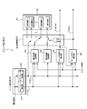
- FIG. 2 is a block diagram illustrating an example of the configuration of an electronic device according to an embodiment of the present technology.
- FIG. 3 is a block diagram showing an example of a functional configuration of a command detection unit in an electronic device according to an embodiment of the present technology.
- FIG. 4 is a sequence for explaining an example of the operation of the command detection unit in the electronic device according to the embodiment of the present technology.
- FIG. 5 is a sequence for explaining an example of the operation of the command detection unit in the electronic device according to the embodiment of the present technology.
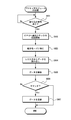
- FIG. 6 is a flowchart for explaining an example of the operation of the processor module in the electronic device according to the embodiment of the present technology.
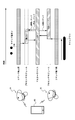
- FIG. 7 is a sequence diagram for explaining the operation of the wireless device system according to the embodiment of the present technology.
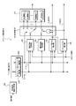
- FIG. 8 is a block diagram showing another example of the functional configuration of the command detection unit in the electronic device according to the
- FIG. 1 is a diagram showing an example of an external configuration of a wireless device according to an embodiment of the present technology.
- the electronic device 1 of the present embodiment is typically a small electronic device that operates in response to a user's touch operation, and the true wireless earphone is an example thereof.
- the electronic device 1 will be described as being a true wireless earphone conforming to the Bluetooth® communication standard.
- a true wireless earphone is a slave device that functions in cooperation with a master device such as a smartphone, but the electronic device 1 of the present embodiment is not limited to such a device, and functions by itself. There may be.
- the appearance of the electronic device 1 is substantially defined by an earpiece-shaped housing 10 molded to fit the shape of a human outer ear.
- a power supply and a control LSI chip are housed inside the housing 10.
- a part 10a on the surface of the housing 10 is configured to function as a touch sensor that is sensitive to a touch operation by the user. The user can give a command to the smartphone on the master side via the electronic device 1 by performing various touch operations on the surface 10a of the housing 10.
- the touch operation is a "tap operation” in which the contact time of the user's finger is short (whether it is a single tap or longer), and a “long press operation” in which the contact time of the user's finger is long.
- the single tap operation may be a play / pause command for a music playback application being executed on the smartphone. ..
- the double tap operation may be a cue command for the next song
- the triple tap operation may be a cue command for the previous or playing song.
- the combination of the single tap operation and the long press operation may be a song fast forward command
- the combination of the double tap operation and the long press operation may be a song fast rewind command.
- FIG. 2 is a block diagram showing an example of the configuration of an electronic device according to an embodiment of the present technology.
- the electronic device 1 of the present embodiment includes, for example, a power supply unit 21, a user interface unit 22, a command detection unit 23, a processor module 24, and a communication module 25.
- the command detection unit 23, the processor module 24, and the communication module 25 can be integrally configured as a control LSI chip.
- the power supply unit 21 supplies the necessary power to each component in the electronic device 1.
- the power source of the power supply unit 21 is, for example, a secondary battery such as a lithium ion battery, but the power source is not limited to this.
- the power supply unit 21 may include, for example, a wireless power supply unit (not shown) that can be filled by wireless power supply from the outside.
- the user interface unit 22 detects an operation (touch operation) due to contact of the user's finger or the like with the housing surface 10a.
- the user interface unit 22 includes, for example, a capacitance type or pressure sensitive type touch sensor 211.
- the user interface unit 22 outputs a sequence of signals (hereinafter referred to as “operation signals”) corresponding to the touch operation detected by the touch sensor 221.
- the sequence of operation signals is, for example, a value indicating a state in which there is no touch operation on the housing 10 (for example, L or 0 level) and a value indicating a state in which there is a touch operation on the housing 10 (for example, H or 1 level). It consists of.
- the user interface unit 22 is configured to output a continuous H-level signal sequence while the user's finger is in contact with the housing 10, but is not limited to this, for example. It may be configured to continuously output a pulsed signal sequence according to a predetermined operating clock. Further, in the present disclosure, the user interface unit 22 is configured to detect physical contact with a user's finger or the like, but is not limited to this, and may be configured to detect, for example, a close state. The user interface unit 22 is configured to operate by receiving power supplied from the power supply unit 21 even in the stop mode described later.
- the command detection unit 23 receives a sequence of operation signals output from the user interface unit 22, and detects a command for the processor module 24 based on the sequence of the received operation signals. Further, the command detection unit 23 acquires or calculates the time and number of touch operations based on the sequence of the received operation signals, and writes or holds them in the register 231 at a predetermined timing.
- the register 231 is configured to be referenceable by the processor module 24.
- the command detection unit 23 may be configured by hardware that does not include a high-performance arithmetic circuit such as a CPU capable of executing a program so that the power consumption can be suppressed as low as possible.
- the command detection unit 23 is configured to operate by receiving power from the power supply unit 21 even in the stop mode described later.
- the command detection unit 23 recognizes that in the sequence of the received operation signal, when the L level continues for a predetermined time after the H level, some command is included in the sequence up to that point. That is, the command detection unit 23 detects the command in the sequence of the operation signal by detecting the break of the touch operation according to the length of the duration of the no-signal state in the sequence of the operation signal. When the command detection unit 23 determines that the command has been detected, the command detection unit 23 outputs a command detection signal to the processor module 24.
- the processor module 24 comprehensively controls the operation of the electronic device 1.
- the processor module 24 may include, for example, a CPU 241 and a memory 242 used thereof.
- a control program and various data are stored in the memory 242.
- the processor module 24 has an operation mode for executing a predetermined control program or the like according to the supply of a predetermined operation clock from a clock circuit (not shown), and all programs by stopping the supply of the predetermined operation clock. It has a stop mode to stop the execution of.
- the processor module 24 shifts from the operation mode to the stop mode, for example, when the power is turned off by a predetermined touch operation or when there is no touch operation for a predetermined time.
- the processor module 24 is a start unit that controls to start supplying a predetermined operation clock and shift to the operation mode by using an input (interrupt) of a predetermined signal as a trigger in the stop mode.
- the activation unit 243 may be configured by, for example, a peripheral circuit of the CPU 241 (for example, a chipset), but is not limited to this, and may be configured by an internal circuit of the CPU 241 connected to a specific port of the CPU 241.
- the stop mode is described as a state in which the supply of a predetermined operating clock is stopped, but the present disclosure is not limited to this, and for example, a state in which the frequency of the operating clock is lower than in the normal state or , May include the state of stopping the supply of power. As described above, the power consumption can be reduced by putting the processor module 24 into the stop mode.
- the processor module 24 executes a control program when it is in an operation mode, and realizes a predetermined function according to the execution of the control program. That is, in the operation mode, when the processor module 24 receives the command detection signal from the command detection unit 23, it immediately refers to the register 231 and fetches (acquires) the contents held in the register 231 to execute the command interpretation process. The command obtained in this manner is transmitted to the master device via the communication module 25. On the other hand, when the processor module 24 is in the stop mode, only the start unit 243 can receive the command detection signal.
- the activation unit 243 When the activation unit 243 detects a command detection signal, the activation unit 243 controls the processor module 24 to start supplying a predetermined operation clock to activate the CPU 241, thereby shifting the processor module 24 to the operation mode. .. As a result, the processor module 24 executes the command interpretation process with reference to the register 231 and transmits the interpreted command to the smartphone via the communication module 25. When transmitting a command to the smartphone, the processor module 24 may, for example, add or include time information to the command.
- the communication module 25 performs wireless communication with another device, for example, a master device such as a smartphone, in accordance with the Bluetooth (registered trademark) standard.
- a master device such as a smartphone
- the communication module 25 is configured separately from the processor module 24, but may be configured as part of the chipset of the processor module 24.
- the electric device 1 may include a real-time clock (RTC) circuit in which a clock function is mounted.
- the RTC circuit operates by a backup power supply separately from the power supply of the power supply unit 21.
- FIG. 3 is a block diagram showing an example of the functional configuration of the command detection unit in the wireless device according to the embodiment of the present technology.
- the command detection unit 23 includes, for example, a register 231, an edge detection unit 232, an operation time measurement unit 233, an operation count measurement unit 234, a command delimiter detection unit 235, and a timeout detection unit 236. And an output control unit 237.
- the edge detection unit 232 detects, for example, the rising edge detection unit 2321 that detects the rising edge (from L level to H level) of the signal in the sequence of the operation signal, and the falling edge (from H level to L level) of the signal edge. It is configured to include a falling edge detection unit 2322.
- the rising edge detection unit 2321 outputs the rising edge detection signal E_riseE_rise when detecting the rising edge of the operation signal, while the falling edge detecting unit 2322 outputs the falling edge detection signal E_all when detecting the falling edge of the operation signal. do.
- the operation time measurement unit 233 measures the time when the touch operation is performed by the user, and holds the measured time as the touch operation time.
- the held touch operation time is read out by detecting the falling edge of the operation signal. That is, when the operation time measuring unit 233 receives the rising edge detection signal E_rise from the rising edge detecting unit 2321, the operation time measuring unit 233 triggers the rising edge detection signal E_all from the falling edge detecting unit 2322 according to a clock signal (not shown). Measure the elapsed time until you receive it. If the tap operation by the user is too fast (that is, the contact time is very short), the time of the touch operation cannot be measured correctly even though the touch operation is performed. Therefore, the rising edge detection signal E_rise A delay portion (not shown) that gives a delay to the device may be provided.
- the operation count measuring unit 234 counts up the count value and temporarily holds it each time it receives the falling edge detection signal E_fall from the falling edge detecting unit 2322.
- the held count value is output triggered by the detection or timeout of the command delimiter by the command delimiter detection unit 235 described later. Further, the operation count measuring unit 234 resets the count value when the count value is read out.
- the command delimiter detection unit 235 detects the command delimiter in the sequence of operation signals. That is, when the command delimiter detection unit 235 receives the falling edge detection signal E_all from the falling edge detection unit 2322, the command delimiter detection unit 235 uses this as a trigger to measure the elapsed time of the L level state according to a clock signal (not shown). That is, the measurement by the command delimiter detection unit 235 is once reset by receiving the rising edge detection signal E_rise from the rising edge detection unit 2321. When the command delimiter detection unit 235 determines that the measured elapsed time exceeds a predetermined threshold value, it considers that the command input by the user's touch operation is completed, and outputs the command detection signal C_detect.
- the command delimiter detection unit 235 determines that the command input has not been completed and measures the measurement time. To reset. As described above, in this example, the command delimiter detection unit 235 detects the command delimiter by determining whether or not a predetermined time has elapsed from the falling edge immediately before the operation signal. For example, when the touch operation by the user is a combination of several operation actions such as a double tap operation, and the next tap is performed without a break after the tap, the command delimiter detection unit 235 uses the user's touch operation. Judges that is still ongoing.
- the command delimiter detection unit 235 outputs the command detection signal C_detect to the timeout detection unit 236 and the output control unit 237, and also outputs the command detection signal to the processor module 24.
- the processor module 24 receives the command detection signal C_detect in the normal operation mode, it immediately refers to the register 231, fetches the contents held in the register 231, executes the command interpretation process, and interprets the command. Is transmitted to the smartphone via the communication module 25.
- the activation unit 243 receives the command detection signal C_detect and controls the processor module 24 to start supplying a predetermined operation clock to start the CPU 241. As a result, the processor module 24 is shifted to the operation mode.
- the time-out detection unit 236 monitors whether or not one touch operation (for example, the double tap operation is one touch operation) is performed within a predetermined effective operation time, and the predetermined effective operation time has elapsed. In this case, the timeout signal Timeout is output. That is, when the timeout detection unit 236 receives the first rising edge detection signal E_rise from the rising edge detection unit 2321, the timeout detection unit 236 uses this as a trigger to measure the elapsed time according to a clock signal (not shown). When the time-out detection unit 236 determines that the elapsed time exceeds a predetermined threshold value, the time-out detection unit 236 outputs a time-out signal Timeout.
- one touch operation for example, the double tap operation is one touch operation
- time-out detection unit 236 resets the measurement time when it receives the command detection signal C_detect from the command delimiter detection unit 235.
- the time-out signal Timeout is output to the output control unit 237 and output to the processor module 24.
- the processor module 24 receives the timeout signal Timeout in the normal operation mode, the processor module 24 performs processing instead of the command detection signal C_detect. That is, the processor module 24 immediately refers to the register 231 and fetches the contents held in the register 231 to execute the command interpretation process, and the command obtained thereby is transmitted to the master device via the communication module 25. Send.
- the output control unit 237 outputs the touch operation time measured by the operation time measurement unit 233 and the number of touch operations measured by the operation count measurement unit 234 to the register 231 at a predetermined timing, respectively, to a predetermined output destination. Control so that it is done. For example, the output control unit 237 selectively and sequentially switches the output destination of the touch operation time read from the operation time measurement unit 233 each time the rising edge detection signal E_rise is received from the falling edge detection unit 2322. As a result, the touch operation time is sequentially written in the specific storage area of the register 231.
- the output control unit 237 when the output control unit 237 receives the command detection signal C_detect from the command delimiter detection unit 235, the output control unit 237 controls so that the number of touch operations read from the operation count measurement unit 234 is output to the register 231. As a result, the number of touch operations is written and updated in the specific storage area of the register 231.
- FIG. 4 is a sequence for explaining an example of the operation of the command detection unit in the electronic device according to the embodiment of the present technology. That is, the figure (a) shows an operation example of the command detection unit 23 when the user performs a single tap operation, and the figure (b) shows an operation example of the command detection unit 23 when the user double taps the operation. FIG. 3C shows an operation example of the command detection unit 23 when the user performs a triple tap operation.
- the operation time measuring unit 233 starts measuring the touch operation time by the rising edge detection signal E_rise from the rising edge detecting unit 2321.
- the timeout detecting unit 236 Also measures the time for a timeout.
- the operation time measurement unit 233 stops the time measurement by the falling edge detection signal E_all, while the operation number measurement unit 234 counts up the count value by one.
- the output control unit 237 controls the output so that the current measurement time (for example, 200 ms) is written in the predetermined storage area of the register 231 and the number of times (for example, once) is written in the predetermined storage area. The output is controlled so that it can be used.
- the command detection unit 23 outputs the command delimiter detection signal C_detect when a predetermined time has elapsed from the time when the falling edge detection signal E_fall is received.
- the time-out detection unit 236 is reset because the command delimiter detection signal C_detect is output before the elapsed time from the first rising edge detection signal E_rise times out.
- the operation time measuring unit 233 starts measuring the touch operation time by the first rising edge detection signal E_rise from the rising edge detecting unit 2321.
- the time-out detection unit 236 measures the time for the time-out.
- the operation time measurement unit 233 stops the time measurement by the falling edge detection signal E_all, and the operation number measurement unit 234 counts up the count value by one.
- the output control unit 237 controls the output so that the time (for example, 200 ms) based on the current measurement time is written to the predetermined storage area of the register 231 and the number of times (for example, once) is the predetermined storage. Control the output so that it is written to the area.
- the operation time measuring unit 233 starts measuring the touch operation time by the second rising edge detection signal E_rise from the rising edge detecting unit 2321. Subsequently, the operation time measurement unit 233 stops the time measurement by the falling edge detection signal E_all, and the operation number measurement unit 234 counts up the count value by one.
- the output control unit 237 controls the output so that the time based on the current measurement time (for example, 195 ms) is written to the predetermined storage area of the register 231 and the number of times (for example, twice) is the predetermined storage. Control the output so that it is written to the area. Then, the command detection unit 23 outputs the command delimiter detection signal C_detect when a predetermined time has elapsed from the time when the second falling edge detection signal E_file is received.
- the operation time measuring unit 233 measures the time from receiving the rising edge detection signal E_rise to receiving the falling edge detection signal E_all, and the operation count measuring unit 234 receives each time the falling edge detection signal E_fall is received. In addition, the count value is counted up. Further, when the output control unit 237 receives the falling edge detection signal E_fall, the output control unit 237 controls the output so that the time and the number of times measured up to that point are written in the predetermined storage area of the register 231. Then, the command detection unit 23 outputs the command delimiter detection signal C_detect when a predetermined time has elapsed from the time when the third falling edge detection signal E_file is received.
- FIG. 5 is a sequence for explaining an example of the operation of the command detection unit in the electronic device according to the embodiment of the present technology. That is, FIGS. (A) and (b) show an operation example of the command detection unit 23 when the user presses and holds the command after a single tap operation, while FIG. 3 (b) shows a time-out when the long press operation times out. An operation example of is shown.
- FIG. 4A is different from the example of the double tap operation shown in FIG. 4B in that the second touch operation by the user is a long press operation.
- the command delimiter detection unit 235 outputs the command delimiter detection signal C_detect when a predetermined time has elapsed from the time when the second falling edge detection signal E_fall is received before the timeout.
- the user has performed a long press operation for a long time exceeding a predetermined threshold value. Therefore, when the time-out detection unit 236 determines that the measurement time exceeds a predetermined threshold value (time-out line), the time-out detection unit 236 outputs a time-out signal Timeut. As a result, the output control unit 237 controls the output so that the time and the number of times measured so far are written in the predetermined storage area of the register 231.
- commands are also used for other touch operations by the user, for example, when only a long press operation is performed, when a long press operation is performed after a double tap operation, or when a long press operation is performed after a triple tap operation.
- the detection unit 23 operates in the same manner, holds the sequence of operation signals in the register 231 and outputs the command detection signal C_detect or the timeout signal Timeout.
- FIG. 6 is a flowchart for explaining an example of the operation of the processor module in the electronic device according to the embodiment of the present technology, and specifically, the flow of processing when the processor module 24 is in the stop mode will be described. is doing.
- the activation unit 243 monitors whether or not there is an interrupt of the command detection signal C_detect or the timeout signal Timeout from the command detection unit 23 (S601). In this state, the CPU 241 is not supplied with the predetermined operating clock and completely stops the execution of the control program, whereby the electronic device 1 keeps the power consumption as low as possible.
- the activation unit 243 When the activation unit 243 detects an interrupt of the command detection signal C_detect or the timeout signal Timeout (Yes in S601), the activation unit 243 controls so that the supply of a predetermined operation clock to the CPU 241 is started (S602). In response to this, the CPU 241 performs a startup process and shifts to the operation mode (S603).
- the CPU 241 refers to the register 231 of the command detection unit 23, and reads out the data regarding the time and the number of touch operations from the register 231 (S604).
- the CPU 241 interprets the read data (S605) and determines whether or not it can be recognized as a predetermined command (S606).
- the CPU 241 transmits the recognized command to a master device such as a smartphone via the communication module 25 (S607). After that, the CPU 241 waits until the next interrupt is generated while still in the operation mode.
- the CPU 241 performs error processing such as resetting the contents of the register 231 to perform an operation mode. It waits until the next interrupt.
- the operation of the processor module 24 in the operation mode is different from the stop mode in that there is no processing of S602 and S603 described above, and thus the description thereof will be omitted.
- the command detection unit 23 is typically composed of hardware that does not include a high-performance arithmetic circuit such as a CPU capable of executing a program, and thus is a user.
- the power consumption can be kept low while the electronic device 1 is not in use.
- the command detection unit 23 holds the sequence of the operation signal based on the user's touch operation in the register 231 when the CPU 241 is in the stop mode, the CPU 241 shifts from the stop mode to the operation mode. , The contents of register 231 can be referred to immediately.
- the input by the user's touch operation performed before the CPU 241 operates can be effectively accepted, and the command can be used immediately after the CPU 241 starts the operation.
- the command detection unit 23 is configured to detect a command based on a single tap operation, a double tap operation, or a long press operation. It may be configured to detect a command based on an operation of strongly pressing the surface 10a of 10 with a finger (3D touch operation).
- the user interface unit 22 outputs a sequence of operation signals only when it is determined that the strength of the user's touch operation exceeds a predetermined threshold value.
- the command detection unit 23 may further include an operation signal strength determination unit 238, as shown in FIG.
- the user interface unit 22 outputs a sequence of operation signals having a level value according to the strength of the user's touch operation, and the operation signal strength determination unit 238 outputs the strength (amplitude) of the operation signal from the user interface unit 22. Only when the value exceeds a predetermined threshold value, the sequence of the operation signal is output to the edge detection unit 232.
- the command detection unit 23 stores the time and number of touch operations based on the sequence of operation signals in the register 231 only when the strength of the operation signal exceeds a predetermined threshold value, and determines the predetermined value. At the timing, the command delimiter detection signal C_register is output.
- the user interface unit 22 outputs a sequence of operation signals only when the user's finger touches a specific part among a plurality of touch-operable parts on the housing surface 10a. You may output it.
- the command detection unit 23 may include a position detection unit (not shown) that detects the operated position based on the sequence of operation signals, and may be configured to operate according to the detected position.
- the user interface unit 22 not only detects a tap operation on the housing surface 10a, but also detects a change in the contact position of the surface 10a as in a flick operation, for example. It may be configured.
- the command detection unit 23 stores the type, time, and number of touch operations based on the sequence of operation signals in the register 231 and outputs the command delimiter detection signal C_detect at a predetermined timing.
- the command detection unit 23 can determine that the operation is erroneous, for example, when the user accidentally touches the housing 10, avoids unnecessary startup of the CPU 241 and saves power. Can be planned.
- FIG. 7 is a sequence diagram for explaining the operation of the wireless device system according to the embodiment of the present technology.
- the wireless device system of the present embodiment includes an electronic device 1 composed of a pair of first device 1A and second device 1B, and a master device MD such as a smartphone.
- the hardware / software configuration of the pair of first device 1A and second device 1B may be the same.
- the electronic device 1 is a true wireless earphone
- the first device 1A is, for example, a left earphone piece
- the second device 1B is, for example, a right earphone piece.
- the master device MD implements an application program configured to be able to cooperate with the electronic device 1 via Bluetooth (registered trademark) communication.
- the processor module 24 has not received the supply of the predetermined operating clock, the CPU 241 has stopped the execution of the control program, while the user interface unit 22 and the command detection unit 23 have stopped executing the control program. It operates by receiving the minimum power supply from the power supply unit 21. In such a state, as shown in the figure, it is assumed that the user has long-pressed the housing 10 of the second device 1B and double-tapped the housing 10 of the first device 1A during the long-pressing operation. ..
- synchronization information for example, time information
- the device book
- the command detection unit 23B of the second device 1B (hereinafter, similarly, the components in the second device 1B are referred to with "B") is an operation signal based on a long press operation from the user interface unit 22B. The time and the number of times are written to the register 231 based on the sequence of. At this point, the command detection unit 23B has not yet output the command detection signal C_detect or the timeout signal Timeout to the processor module 24B.
- the command detection unit 23A of the first device 1A (hereinafter, similarly, the components in the first device 1A are referred to with "A") is based on the double tap operation from the user interface unit 22A. Based on the sequence of operation signals, the time and the number of times are written to the register 231A, the command is detected, and the command detection signal C_detect is output to the processor module 24A.
- the processor module 24A of the first device 1A starts supplying a predetermined operation clock by an interrupt of the command detection signal C_detect, and shifts to the operation mode.
- the processor module 24 which has shifted to the operation mode acquires a command according to the double tap operation with reference to the register 231 and transmits this to the master device MD via the communication module 25.
- the master device MD is executing an application program under the control of a processor (not shown). When the master device MD receives the command from the first device 1A, it waits until the command is received from the second device 1B.
- the command detection unit 23B of the second device 1B outputs a timeout signal Timeout to the processor module 24B because the time from the start of the long press operation exceeds a predetermined threshold value.
- the processor module 24B transmits a command according to the long press operation to the master device MD.
- the master device MD When the master device MD receives a command from the second device 1B, the master device MD interprets the command. When the master device MD determines that the command is a command that follows a long press operation as a result of interpretation, the first device issues a synchronization command that synchronizes the time information between the devices in combination with the command that follows the double tap operation received earlier. It is transmitted to 1A and the second device 1B, and further, a stop command for shifting one device to the stop mode is transmitted to the first device 1A.
- the first device 1A and the second device 1B When the first device 1A and the second device 1B receive the synchronization command from the master device MD, the first device 1A and the second device 1B update the time information on their own RTC circuit according to the time information included in the synchronization command. As a result, the time information of the first device 1A and the second device 1B will be synchronized. Further, when the first device receives the stop command from the master device MD, it shifts from the operation mode to the stop mode, stops the execution of the control program, and stops the supply of the predetermined clock operation. As a result, the user can use the second device 1B only, while suppressing the power consumption in the first device 1A.
- steps, actions or functions may be performed in parallel or in different order as long as the results are not inconsistent.
- the steps, actions and functions described are provided by way of example only, and some of the steps, actions and functions may be omitted and combined with each other to the extent that they do not deviate from the gist of the invention. It may be one, or other steps, actions or functions may be added.
- control module of the electronic device 1 configured so that the processor module 24 shifts to the stop mode by stopping the supply of a predetermined operation clock to the CPU 241 is shown.
- the control module may be configured as a stop mode so that the frequency of the operating clock is lower than during normal operation.
- the control module may be configured to stop the supply of power from the power supply unit 12 as a stop mode.
- the activation unit 243 detects an interrupt of the command detection signal C_detect or the timeout signal Timeout, the activation unit 243 starts supplying power from the power supply unit 12 and shifts the CPU 241 to the operation mode.
- the power consumption while the user is not using the electronic device 1 can be suppressed to a low level.
- a processor module having an operation mode for executing a predetermined control program by receiving a supply of a predetermined operation clock and a stop mode for stopping without receiving the supply of the predetermined operation clock.
- a user interface unit that detects a user's touch operation and outputs a sequence of operation signals corresponding to the detected touch operation.
- a command detection unit that detects a command corresponding to the touch operation based on the output sequence of the operation signal is provided. The command detection unit controls the processor module to shift from the stop mode to the operation mode when the command is detected when the processor module is in the stop mode. Electronics.
- the command detection unit detects the time and number of touch operations based on the sequence of the operation signals, and includes a register holding the detected time and number of touch operations. device.
- the command detection unit detects one of the commands based on the sequence of the operation signals.
- the command detection unit detects the command by detecting the delimiter of the one command based on the falling edge in the sequence of the operation signal.
- the command detection unit outputs a command detection signal to the processor module when a predetermined time has elapsed from the falling edge.
- the command detection unit outputs a timeout signal to the processor module when a predetermined effective operation time has elapsed from the first rising edge in the sequence of operation signals.
- the command detector receives power required to detect the command when the processor module is in the stop mode.
- the activation unit With more starters Upon receiving the command detection signal, the activation unit starts supplying the predetermined operation clock to the processor module, and shifts the processor module from the stop mode to the operation mode.
- the electronic device according to (5) above. With more starters Upon receiving the timeout signal, the activation unit starts supplying the predetermined operation clock to the processor module, and shifts the processor module from the stop mode to the operation mode.
- the processor module When the processor module shifts from the stop mode to the operation mode, the processor module refers to the register and acquires the time and the number of times of the touch operation held in the register.
- the processor module sends a command based on the time and number of touch operations acquired from the register to an external device.
- the touch operation is a single or more tap operation, a long press operation, a flick operation, and / or a 3D touch operation.
- An electronic device including a first device and a second device.
- Each of the first device and the second device A processor module having an operation mode for executing a predetermined control program by receiving a supply of a predetermined operation clock and a stop mode for stopping without receiving the supply of the predetermined operation clock.
- a user interface unit that detects a user's touch operation and outputs a sequence of operation signals corresponding to the detected touch operation.
- a command detection unit that detects a command corresponding to the touch operation based on the output sequence of the operation signal is provided.
- Each command detection unit controls the processor module to shift from the stop mode to the operation mode when the command is detected when the processor module is in the stop mode.
- Each of the processor modules sends the detected command to an external device in the operating mode.
- Each of the first device and the second device It operates under the control of the external device according to a combination of sequences of the operation signals from each of the user interface units.
- Electronics. (14) It is a method of controlling the operation of electronic devices.
- the processor module When the processor module is in a stop mode in which it is stopped without being supplied with a given operating clock.
- Receiving a sequence of operation signals according to the user's touch operation detected by the user interface unit To detect a command corresponding to the touch operation based on the received sequence of the operation signals,
- the processor module is controlled to shift from the stop mode to the operation mode in which the predetermined control program is executed by receiving the supply of the predetermined operation clock. Operation control method.
Landscapes
- Engineering & Computer Science (AREA)
- Theoretical Computer Science (AREA)
- General Engineering & Computer Science (AREA)
- Physics & Mathematics (AREA)
- General Physics & Mathematics (AREA)
- Human Computer Interaction (AREA)
- Health & Medical Sciences (AREA)
- Multimedia (AREA)
- Audiology, Speech & Language Pathology (AREA)
- General Health & Medical Sciences (AREA)
- Signal Processing (AREA)
- Acoustics & Sound (AREA)
- Telephone Function (AREA)
Abstract
本発明は、動作クロックの供給を受けて所定の制御プログラムを実行する動作モードと前記動作クロックの供給を受けることなく停止している停止モードとを有するプロセッサモジュールと、ユーザのタッチ操作を検出して、検出した前記タッチ操作に応じた操作信号のシーケンスを出力するユーザインターフェース部と、出力される前記操作信号のシーケンスに基づいて、前記タッチ操作に応じたコマンドを検出するコマンド検出部とを備える電子機器である。前記コマンド検出部は、前記プロセッサモジュールが前記停止モードにある場合に、前記コマンドを検出した場合に、前記プロセッサモジュールが前記停止モードから前記動作モードに移行するように制御を行う。
Description
本発明は、電子機器に関し、特に、タッチ式のユーザインターフェースを備えた小型の電子機器及びこれの動作制御方法に関する。
小型電子機器の代表的なものとして、近年、トゥルーワイヤレスイヤホンが急速に普及しつつある。トゥルーワイヤレスイヤホンは、左右のイヤホンピースが完全に独立したBluetooth(登録商標)通信規格に従ったワイヤレスイヤホンである。トゥルーワイヤレスイヤホンは極めて小さな筐体に作り込まれているため、設計上の制約が非常に多い。例えば、トゥルーワイヤレスイヤホン本体の装着性やデザイン性から物理的なスイッチ動作機構をできるだけ排除しつつ、操作性を考慮したユーザインターフェースが望まれている。また、本体に内蔵されるバッテリーは小容量である一方、長時間のバッテリー駆動時間の確保のために、省電力化・低電力化の要求が極めて強い。
例えば、下記特許文献1は、機器の省電力化のための技術として、スタンバイモードと当該スタンバイモードにおける消費電力よりも低い消費電力となる省電力モードとを有する機器において、省電力モード時、タッチパネルにおける位置情報を検出する座標検出回路の動作を停止し、特定のスイッチ操作によりスタンバイモードに移行し、該座標検出回路を作動させ、操作部を操作可能とする技術を開示する。
上記特許文献1では、タッチパネルのタッチセンサ機能を停止することにより省電力化が図られる一方、機器全体を統括的に制御するメイン制御手段は省電力モードで動作する構成が採用されている。したがって、メイン制御手段を構成するCPU等プロセッサモジュールは、依然として電力を消費しながら動作しなければならない。
一方、トゥルーワイヤレスイヤホンのような小型の電子機器では、プロセッサモジュールが占める消費電力の割合は相対的に大きいため、省電力モードであってもプロセッサモジュールを常に動作させておく特許文献1の技術を適用することは現実的ではなかった。
そこで、本開示では、トゥルーワイヤレスイヤホンのような小型の電子機器に適合された新たな省電力化・低電力化技術を提供することを目的としている。
より具体的には、本技術は、待機状態又は本来動作を停止させた状態において、更なる省電力化・低電力化を可能にした小型の電子機器及びこれの動作制御方法を提供することを目的としている。
また、本技術は、省電力化・低電力化を図りつつ、動作が停止したCPUを効率的に起動可能にした小型の電子機器及びこれの動作制御方法を提供することを目的としている。
更に、本技術は、CPUが動作する前になされたユーザのタッチ操作による入力を有効に受け付けることを可能にした小型の電子機器及びこれの動作制御方法を提供することを目的としている。
上記課題を解決するための本技術は、以下に示す発明特定事項乃至は技術的特徴を含んで構成される。
ある観点に従う本技術は、所定の動作クロックの供給を受けて所定の制御プログラムを実行する動作モードと前記所定の動作クロックの供給を受けることなく停止している停止モードとを有するプロセッサモジュールと、ユーザのタッチ操作を検出して、検出した前記タッチ操作に応じた操作信号のシーケンスを出力するユーザインターフェース部と、出力される前記操作信号のシーケンスに基づいて、前記タッチ操作に応じたコマンドを検出するコマンド検出部とを備える電子機器である。前記コマンド検出部は、前記プロセッサモジュールが前記停止モードにある場合に、前記コマンドを検出した場合に、前記プロセッサモジュールが前記停止モードから前記動作モードに移行するように制御を行うように構成される。
また、別の観点に従う本技術は、第1デバイスと第2デバイスとを備える電子機器である。前記第1デバイス及び前記第2デバイスのそれぞれは、所定の動作クロックの供給を受けて所定の制御プログラムを実行する動作モードと前記所定の動作クロックの供給を受けることなく停止している停止モードとを有するプロセッサモジュールと、ユーザのタッチ操作を検出して、検出した前記タッチ操作に応じた操作信号のシーケンスを出力するユーザインターフェース部と、出力される前記操作信号のシーケンスに基づいて、前記タッチ操作に応じたコマンドを検出するコマンド検出部とを備える。各前記コマンド検出部は、前記プロセッサモジュールが前記停止モードにある場合に、前記コマンドを検出した場合に、前記プロセッサモジュールが前記停止モードから前記動作モードに移行するように制御を行う。また、各前記プロセッサモジュールは、前記動作モードにおいて、検出されたコマンドを外部のデバイスに送信する。更に、前記第1デバイス及び前記第2デバイスのそれぞれは、各前記ユーザインターフェース部からの操作信号のシーケンスの組み合わせに従って、前記外部のデバイスの制御の下、動作する。
また、別の観点に従う本技術は、電子機器の動作制御方法である。前記方法は、プロセッサモジュールが所定の動作クロックの供給を受けることなく停止している停止モードにある場合において、ユーザインターフェース部により検出されたユーザのタッチ操作に応じた操作信号のシーケンスを受け取ることと、受け取った前記操作信号のシーケンスに基づいて、前記タッチ操作に応じたコマンドを検出することと、前記コマンドが検出された場合に、前記プロセッサモジュールを前記停止モードから前記所定の動作クロックの供給を受けて所定の制御プログラムを実行する動作モードに移行するように制御を行うこととを実行することを含む。
なお、本明細書等において、手段とは、単に物理的手段を意味するものではなく、その手段が有する機能をソフトウェアによって実現する場合も含む。また、1つの手段が有する機能が2つ以上の物理的手段により実現されても、2つ以上の手段の機能が1つの物理的手段により実現されてもよい。また、「システム」とは、複数の装置(又は特定の機能を実現する機能モジュール)が論理的に集合した物のことをいい、各装置や機能モジュールが単一の筐体内にあるか否かは問わない。
本発明の他の技術的特徴、目的、及び作用効果乃至は利点は、添付した図面を参照して説明される以下の実施形態により明らかにされる。本明細書に記載された効果はあくまで例示であって限定されるものではなく、また他の効果があっても良い。
以下、図面を参照して本技術の実施の形態を説明する。ただし、以下に説明する実施形態は、あくまでも例示であり、以下に明示しない種々の変形や技術の適用を排除する意図はない。本技術は、その趣旨を逸脱しない範囲で種々変形(例えば各実施形態を組み合わせる等)して実施することができる。また、以下の図面の記載において、同一又は類似の部分には同一又は類似の符号を付して表している。図面は模式的なものであり、必ずしも実際の寸法や比率等とは一致しない。図面相互間においても互いの寸法の関係や比率が異なる部分が含まれていることがある。
[第1の実施形態]
図1は、本技術の一実施形態に係るワイヤレスデバイスの外観構成の一例を示す図である。本実施形態の電子機器1は、典型的には、ユーザのタッチ操作に応じて動作する小型の電子機器であり、トゥルーワイヤレスイヤホンは、その一例である。本開示では、電子機器1は、Bluetooth(登録商標)通信規格に適合したトゥルーワイヤレスイヤホンであるものとして説明する。一般的には、トゥルーワイヤレスイヤホンは、スマートフォン等のマスターデバイスと連携して機能するスレーブデバイスであるが、本実施形態の電子機器1は、そのようなものに限られず、それ単体で機能するものであっても良い。
図1は、本技術の一実施形態に係るワイヤレスデバイスの外観構成の一例を示す図である。本実施形態の電子機器1は、典型的には、ユーザのタッチ操作に応じて動作する小型の電子機器であり、トゥルーワイヤレスイヤホンは、その一例である。本開示では、電子機器1は、Bluetooth(登録商標)通信規格に適合したトゥルーワイヤレスイヤホンであるものとして説明する。一般的には、トゥルーワイヤレスイヤホンは、スマートフォン等のマスターデバイスと連携して機能するスレーブデバイスであるが、本実施形態の電子機器1は、そのようなものに限られず、それ単体で機能するものであっても良い。
同図に示すように、電子機器1は、人の外耳の形状に適合するように成形されたイヤーピース状の筐体10によって、その外観が略画定されている。同図では、一対のイヤーピースのうちの片方のみが示されている。また、図示されていないが、筐体10の内部には、電源と制御用LSIチップとが収納されている。筐体10の表面の一部10aは、ユーザによるタッチ操作に感応するタッチセンサとして機能するように構成されている。ユーザは、筐体10の表面10aに対して、種々のタッチ操作をすることにより、電子機器1を介して、マスター側のスマートフォンにコマンドを与えることができる。本開示において、タッチ操作とは、ユーザの指の接触時間が短い「タップ操作」(シングルタップであるかそれ以上であるかを問わない。)、ユーザの指の接触時間が長い「長押し操作」、接触後に移動が伴う「フリック操作」、及び/又はあたかも筐体10の表面10aを指で強く押し込むような「3Dタッチ操作」を含み得る。例えば、トゥルーワイヤレスイヤホンとしての電子機器1が、スマートフォンとペアリングされて操作連携している場合に、シングルタップ操作は、スマートフォン上で実行されている音楽再生アプリに対する再生/一時停止コマンドであり得る。また、ダブルタップ操作は、次の曲の頭出しコマンドであり、トリプルタップ操作は、前又は再生中の曲の頭出しコマンドであり得る。また、シングルタップ操作と長押し操作との組み合わせは、曲の早送りコマンドであり、ダブルタップ操作と長押し操作との組み合わせは、曲の早戻しコマンドであり得る。
図2は、本技術の一実施形態に係る電子機器の構成の一例を示すブロックダイアグラムである。同図に示すように、本実施形態の電子機器1は、例えば、電源部21と、ユーザインターフェース部22と、コマンド検出部23と、プロセッサモジュール24と、通信モジュール25とを含み構成される。例えば、コマンド検出部23、プロセッサモジュール24、及び通信モジュール25は、制御用LSIチップとして一体的に構成され得る。
電源部21は、電子機器1内の各コンポーネントに必要な電力を供給する。電源部21の電源は、例えばリチウムイオン電池のような二次電池であるが、これに限られない。電源部21は、例えば、外部からのワイヤレス給電による充填が可能なワイヤレス給電部(図示せず)を含み構成され得る。
ユーザインターフェース部22は、ユーザの指等の筐体表面10aへの接触による操作(タッチ操作)を検出する。ユーザインターフェース部22は、例えば静電容量式や感圧式のタッチセンサ211を含み構成される。ユーザインターフェース部22は、タッチセンサ221により検出したタッチ操作に応じた信号(以下「操作信号」という。)のシーケンスを出力する。操作信号のシーケンスは、例えば、筐体10へのタッチ操作がない状態を示す値(例えばL又は0レベル)と、筐体10へのタッチ操作がある状態を示す値(例えばH又は1レベル)とからなる。本例では、ユーザインターフェース部22は、ユーザの指が筐体10に接触している間、連続的なHレベルの信号シーケンスを出力するように構成されているが、これに限られず、例えば、所定の動作クロックに応じたパルス状の信号シーケンスを連続的に出力するように構成されても良い。また、本開示では、ユーザインターフェース部22は、ユーザの指等の物理的な接触を検出する構成であるが、これに限られず、例えば近接した状態を検出する構成であっても良い。ユーザインターフェース部22は、後述する停止モードにおいても、電源部21から電源の供給を受けて動作するように構成される。
コマンド検出部23は、ユーザインターフェース部22から出力される操作信号のシーケンスを受信して、受信した操作信号のシーケンスに基づいて、プロセッサモジュール24に対するコマンドを検出する。また、コマンド検出部23は、受信した操作信号のシーケンスに基づいて、タッチ操作の時間及び回数を取得ないしは算出して、これらを所定のタイミングでレジスタ231に書き込み、保持する。レジスタ231は、プロセッサモジュール24により参照可能に構成されている。コマンド検出部23は、消費電力ができるだけ低く抑えられるように、典型的には、プログラムを実行可能なCPU等のような高機能な演算回路を含まないハードウェアによって構成され得る。コマンド検出部23は、後述する停止モードにおいても、電源部21から電源の供給を受けて動作するように構成される。
コマンド検出部23は、受信した操作信号のシーケンスにおいて、Hレベルの後、Lレベルが所定の時間継続した場合に、その時点までのシーケンスに何らかのコマンドが含まれることを認識する。つまり、コマンド検出部23は、操作信号のシーケンス中の無信号の状態の持続時間の長短に従ってタッチ操作の区切りを検出することにより、操作信号のシーケンス中のコマンドを検出する。コマンド検出部23は、コマンドを検出したと判断した場合、コマンド検出信号をプロセッサモジュール24に出力する。
プロセッサモジュール24は、電子機器1の動作を統括的に制御する。プロセッサモジュール24は、例えば、CPU241とその利用に供されるメモリ242とを含み構成され得る。メモリ242には、例えば、制御プログラムや種々のデータが格納される。本開示では、プロセッサモジュール24は、クロック回路(図示せず)からの所定の動作クロックの供給に従って所定の制御プログラム等を実行する動作モードと、所定の動作クロックの供給を停止してすべてのプログラムの実行を停止させる停止モードとを有する。プロセッサモジュール24は、例えば、ユーザが所定のタッチ操作により電源OFFさせた場合や、所定の時間、タッチ操作がなかった場合に、動作モードから停止モードに移行する。また、プロセッサモジュール24は、後述するように、停止モードにおいて所定の信号の入力(割り込み)をトリガにして、所定の動作クロックの供給を開始させ、動作モードに移行させるように制御を行う起動部243を備える。起動部243は、例えば、CPU241の周辺回路(例えばチップセット)により構成され得るが、これに限られず、CPU241の特定のポートに接続されるCPU241の内部回路により構成されても良い。なお、本開示では、停止モードは、所定の動作クロックの供給を停止した状態をいうものとして説明しているが、これに限られず、例えば、動作クロックの周波数を通常時よりも低くする状態や、電源の供給を停止する状態を含み得る。このように、プロセッサモジュール24が停止モードになることにより、電力の消費を削減することができる。
プロセッサモジュール24は、例えば、動作モードにある場合に、制御プログラムを実行し、該制御プログラムの実行に従って所定の機能を実現する。すなわち、プロセッサモジュール24は、動作モードにおいて、コマンド検出部23からコマンド検出信号を受け取ると、直ちにレジスタ231を参照し、レジスタ231に保持された内容をフェッチ(取得)して、コマンド解釈処理を実行して得られたコマンドを、通信モジュール25を介してマスターデバイスに送信する。これに対して、プロセッサモジュール24が停止モードである場合、起動部243のみがコマンド検出信号を受け取ることができる。起動部243は、コマンド検出信号を検出すると、プロセッサモジュール24に対して所定の動作クロックの供給が開始するように制御して、CPU241を起動し、これにより、プロセッサモジュール24を動作モードへ移行させる。これにより、プロセッサモジュール24は、レジスタ231を参照してコマンド解釈処理を実行し、解釈したコマンドを、通信モジュール25を介して、スマートフォンに送信する。プロセッサモジュール24は、スマートフォンにコマンドを送信する際、例えば該コマンドに時刻情報を付加し又は含めても良い。
通信モジュール25は、他のデバイス、例えば、スマートフォン等のようなマスターデバイスとの間でBluetooth(登録商標)規格に従った無線通信を行う。本開示では、通信モジュール25は、プロセッサモジュール24とは別に構成されているが、プロセッサモジュール24のチップセットの一部として構成されても良い。
なお、図示していないが、電気機器1は、時計機能が実装されたリアルタイムクロック(RTC)回路を含み得る。RTC回路は、電源部21の電源とは別に、バックアップ電源により動作する。
図3は、本技術の一実施形態に係るワイヤレスデバイスにおけるコマンド検出部の機能的構成の一例を示すブロックダイアグラムである。同図に示すように、コマンド検出部23は、例えば、レジスタ231と、エッジ検出部232と、操作時間計測部233と、操作回数計測部234と、コマンド区切り検出部235と、タイムアウト検出部236と、出力制御部237とを含み構成される。
エッジ検出部232は、例えば、操作信号のシーケンスにおける信号の立上り(LレベルからHレベル)エッジを検出する立上りエッジ検出部2321と、該信号エッジの立下り(HレベルからLレベル)エッジを検出する立下りエッジ検出部2322とを含み構成される。立上りエッジ検出部2321は、操作信号の立ち上がりを検出すると、立上りエッジ検出信号E_riseE_riseを出力する一方、立下りエッジ検出部2322は、操作信号の立ち下がりを検出すると、立下りエッジ検出信号E_fallを出力する。
操作時間計測部233は、ユーザによりタッチ操作がなされた時間を計測し、計測した時間をタッチ操作の時間として保持する。保持されたタッチ操作の時間は、操作信号の立ち下がりの検出により、読み出される。すなわち、操作時間計測部233は、立上りエッジ検出部2321から立上りエッジ検出信号E_riseを受け取ると、これをトリガにして、図示しないクロック信号に従って、立下りエッジ検出部2322から立下りエッジ検出信号E_fallを受け取るまでの経過時間を計測する。なお、ユーザによるタップ操作が早すぎる(すなわち、接触時間が非常に短い)場合、タッチ操作がなされているにも拘わらず、タッチ操作の時間を正しく計測できないことになるため、立上りエッジ検出信号E_riseに遅延を与える遅延部(図示せず)が設けられても良い。
操作回数計測部234は、立下りエッジ検出部2322から立下りエッジ検出信号E_fallを受け取るごとに、カウント値をカウントアップし、一時的に保持する。保持されたカウント値は、後述するコマンド区切り検出部235によるコマンド区切りの検出又はタイムアウトをトリガにして、出力される。また、操作回数計測部234は、カウント値が読み出されると、カウント値をリセットする。
コマンド区切り検出部235は、操作信号のシーケンスにおけるコマンドの区切りを検出する。すなわち、コマンド区切り検出部235は、立下りエッジ検出部2322から立下りエッジ検出信号E_fallを受け取ると、これをトリガにして、図示しないクロック信号に従って、Lレベルの状態が経過した時間を計測する。つまり、コマンド区切り検出部235による計測は、立上りエッジ検出部2321から立上りエッジ検出信号E_riseを受け取ることにより、一旦、リセットされる。コマンド区切り検出部235は、計測した経過時間が所定のしきい値を超えると判断する場合には、ユーザのタッチ操作によるコマンド入力が完了したとみなして、コマンド検出信号C_detectを出力する。一方、コマンド区切り検出部235は、計測した経過時間が所定のしきい値を超える前に、立上りエッジ検出信号E_riseを受け取った場合には、コマンド入力が完了していないと判断して、計測時間をリセットする。このように、本例では、コマンド区切り検出部235は、操作信号の直前の立下りから所定の時間経過したか否かを判断することにより、コマンドの区切りを検出している。例えば、ユーザによるタッチ操作がダブルタップ操作等のようにいくつかの操作アクションの組み合わせである場合、タップ後に間髪入れずに次のタップがなされる場合、コマンド区切り検出部235は、ユーザのタッチ操作が未だ継続中であると判断する。
コマンド区切り検出部235は、コマンド検出信号C_detectをタイムアウト検出部236及び出力制御部237に出力するとともにプロセッサモジュール24に出力する。なお、プロセッサモジュール24は、通常の動作モードにおいて、コマンド検出信号C_detectを受け取ると、直ちにレジスタ231を参照し、レジスタ231に保持された内容をフェッチして、コマンド解釈処理を実行し、解釈したコマンドを、通信モジュール25を介して、スマートフォンに送信する。一方、プロセッサモジュール24が停止モードである場合、起動部243がコマンド検出信号C_detectを受け取って、プロセッサモジュール24に対して所定の動作クロックの供給を開始するように制御して、CPU241を起動し、これにより、プロセッサモジュール24を動作モードへ移行させる。
タイムアウト検出部236は、1つのタッチ操作(例えば、ダブルタップ操作は1つのタッチ操作である。)が所定の有効操作時間内になされたか否かを監視し、該所定の有効操作時間を経過した場合に、タイムアウト信号Timeoutを出力する。すなわち、タイムアウト検出部236は、立上りエッジ検出部2321から最初の立上りエッジ検出信号E_riseを受け取ると、これをトリガにして、図示しないクロック信号に従って、経過時間を計測する。タイムアウト検出部236は、経過時間が所定のしきい値を超えたと判断する場合、タイムアウト信号Timeoutを出力する。また、タイムアウト検出部236は、コマンド区切り検出部235からコマンド検出信号C_detectを受け取ると、計測時間をリセットする。タイムアウト信号Timeoutは、出力制御部237に出力されるとともにプロセッサモジュール24に出力される。なお、プロセッサモジュール24は、通常の動作モードにおいて、タイムアウト信号Timeoutを受けると、コマンド検出信号C_detectに代わり、処理を行う。すなわち、プロセッサモジュール24は、直ちにレジスタ231を参照し、レジスタ231に保持された内容をフェッチして、コマンド解釈処理を実行し、これにより得られたコマンドを、通信モジュール25を介して、マスターデバイスに送信する。
出力制御部237は、操作時間計測部233により計測されたタッチ操作の時間及び操作回数計測部234により計測されたタッチ操作の回数が、それぞれ、所定のタイミングでレジスタ231に所定の出力先に出力されるように、制御を行う。例えば、出力制御部237は、立下りエッジ検出部2322から立上りエッジ検出信号E_riseを受け取るごとに、操作時間計測部233から読み出されるタッチ操作の時間の出力先を選択的に順次に切り替える。これにより、タッチ操作の時間は、レジスタ231の特定の格納領域に順番に書き込まれることになる。また、出力制御部237は、コマンド区切り検出部235からコマンド検出信号C_detectを受け取ると、操作回数計測部234から読み出されるタッチ操作の回数がレジスタ231に出力されるように制御を行う。これにより、タッチ操作の回数は、レジスタ231の特定の格納領域に書き込まれ更新される。
図4は、本技術の一実施形態に係る電子機器におけるコマンド検出部の動作の一例を説明するためのシーケンスである。すなわち、同図(a)は、ユーザがシングルタップ操作した場合のコマンド検出部23の動作例を示し、同図(b)は、ユーザがダブルタップ操作した場合のコマンド検出部23の動作例を示し、同図(c)は、ユーザがトリプルタップ操作した場合のコマンド検出部23の動作例を示している。
同図(a)の例に示すように、操作時間計測部233は、立上りエッジ検出部2321からの立上りエッジ検出信号E_riseにより、タッチ操作の時間の計測を開始する、このとき、タイムアウト検出部236もまた、タイムアウトのための時間を計測する。続いて、立下りエッジ検出信号E_fallにより、操作時間計測部233は時間の計測を停止する一方、操作回数計測部234は、カウント値を1つカウントアップする。これにより、出力制御部237は、現時点の計測時間(例えば200ms)がレジスタ231の所定の格納領域に書き込まれるように出力を制御するとともに、その回数(例えば1回)が所定の格納領域に書き込まれるように出力を制御する。そして、本例では、コマンド検出部23が、立下りエッジ検出信号E_fallを受けた時点から所定の時間が経過したときに、コマンド区切り検出信号C_detectを出力する。なお、タイムアウト検出部236は、最初の立上りエッジ検出信号E_riseからの経過時間がタイムアウトする前にコマンド区切り検出信号C_detectが出力されたため、リセットされる。
また、同図(b)の例に示すように、操作時間計測部233は、立上りエッジ検出部2321からの1つ目の立上りエッジ検出信号E_riseにより、タッチ操作の時間の計測を開始する、また、タイムアウト検出部236は、タイムアウトのための時間を計測する。続いて、立下りエッジ検出信号E_fallにより、操作時間計測部233は時間の計測を停止し、また、操作回数計測部234は、カウント値を1つカウントアップする。これにより、出力制御部237は、現時点の計測時間に基づく時間(例えば200ms)がレジスタ231の所定の格納領域に書き込まれるように出力を制御するとともに、その回数(例えば1回)が所定の格納領域に書き込まれるように出力を制御する。続いて、操作時間計測部233は、立上りエッジ検出部2321からの2つ目の立上りエッジ検出信号E_riseにより、タッチ操作の時間の計測を開始する。続いて、立下りエッジ検出信号E_fallにより、操作時間計測部233は時間の計測を停止し、また、操作回数計測部234は、カウント値を1つカウントアップする。これにより、出力制御部237は、現時点の計測時間に基づく時間(例えば195ms)がレジスタ231の所定の格納領域に書き込まれるように出力を制御するとともに、その回数(例えば2回)が所定の格納領域に書き込まれるように出力を制御する。そして、コマンド検出部23は、2つ目の立下りエッジ検出信号E_fallを受けた時点から所定の時間が経過したときに、コマンド区切り検出信号C_detectを出力する。
また、同図(c)に示すトリプルタップ操作の例においても同様である。すなわち、操作時間計測部233は、立上りエッジ検出信号E_riseを受け取ってから立下りエッジ検出信号E_fallを受け取るまでの時間を計測すると共に、操作回数計測部234は、立下りエッジ検出信号E_fallを受け取るごとに、カウント値をカウントアップする。また、出力制御部237は、立下りエッジ検出信号E_fallを受け取ると、それまでに計測された時間及び回数がレジスタ231の所定の格納領域に書き込まれるように出力を制御する。そして、コマンド検出部23は、3つ目の立下りエッジ検出信号E_fallを受けた時点から所定の時間が経過したときに、コマンド区切り検出信号C_detectを出力する。
図5は、本技術の一実施形態に係る電子機器におけるコマンド検出部の動作の一例を説明するためのシーケンスである。すなわち、同図(a)及び(b)は、ユーザがシングルタップ操作後に長押し操作した場合のコマンド検出部23の動作例を示すが、同図(b)は、長押し操作がタイムアウトした場合の動作例を示している。
同図(a)は、ユーザによる2回目のタッチ操作が長押し操作である点で、図4(b)に示したダブルタップ操作の例と異なっている。同様に、コマンド区切り検出部235は、タイムアウトよりも前に、2つ目の立下りエッジ検出信号E_fallを受けた時点から所定の時間が経過したときに、コマンド区切り検出信号C_detectを出力する。
一方、同図(a)に示す例では、所定のしきい値を超える長い時間に亘ってユーザによる長押し操作が行われている。したがって、タイムアウト検出部236は、計測時間が所定のしきい値(タイムアウトライン)を超えたと判断すると、タイムアウト信号Timeutを出力する。これにより、出力制御部237は、それまでに計測された時間及び回数がレジスタ231の所定の格納領域に書き込まれるように出力を制御する。
なお、図示していないが、ユーザによる他のタッチ操作の場合、例えば、長押し操作のみの場合やダブルタップ操作後に長押し操作をする場合、トリプルタップ操作後に長押し操作をする場合も、コマンド検出部23は、同様に動作して、操作信号のシーケンスをレジスタ231に保持すると共に、コマンド検出信号C_detect又はタイムアウト信号Timeoutを出力する。
図6は、本技術の一実施形態に係る電子機器におけるプロセッサモジュールの動作の一例を説明するためのフローチャートであり、具体的には、プロセッサモジュール24が停止モードにある場合の処理の流れを説明している。
同図に示すように、起動部243は、コマンド検出部23からコマンド検出信号C_detect又はタイムアウト信号Timeoutの割り込みがあるか否かを監視している(S601)。この状態において、CPU241は、所定の動作クロックの供給を受けておらず、制御プログラムの実行を完全に停止し、これにより、電子機器1は、電力の消費を可能な限り低く抑えている。
起動部243は、コマンド検出信号C_detect又はタイムアウト信号Timeoutの割り込みを検出した場合には(S601のYes)、CPU241への所定の動作クロックの供給が開始されるように制御を行い(S602)、これを受けて、CPU241は、起動処理を行い、動作モードに移行する(S603)。
続いて、CPU241は、コマンド検出部23のレジスタ231を参照し、レジスタ231からタッチ操作の時間及び回数に関するデータを読み出す(S604)。次に、CPU241は、読み出したデータを解釈し(S605)、所定のコマンドとして認識することができるか否かを判断する(S606)。CPU241は、読み出したデータを所定のコマンドとして認識することができた場合には(S606のYes)、認識した該コマンドを、通信モジュール25を介して、スマートフォン等のマスターデバイスに送信する(S607)。その後、CPU241は、動作モードのまま、次の割り込みがあるまで待機する。これに対して、CPU241は、読み出したデータを所定のコマンドとして認識することができなかった場合には(S606のNo)、例えばレジスタ231の内容をリセットするなどのエラー処理を行って、動作モードのまま、次の割り込みがあるまで待機する。
なお、動作モードでのプロセッサモジュール24の動作は、上述したS602及びS603の処理がない点で、停止モードと異なるため、その説明を省略する。
以上のように、本実施形態によれば、コマンド検出部23は、典型的には、プログラムを実行可能なCPU等のような高機能な演算回路を含まないハードウェアによって構成されるため、ユーザが電子機器1を使用していない間の消費電力を低く抑えることができる。とりわけ、コマンド検出部23は、CPU241が停止モードにある場合に、ユーザのタッチ操作に基づく操作信号のシーケンスをレジスタ231に保持しておくので、CPU241は、停止モードから動作モードに移行した場合に、直ちにレジスタ231の内容を参照することができる。これにより、CPU241が動作する前になされたユーザのタッチ操作による入力を有効に受け付け、CPU241が動作開始後、直ちに、該コマンドを利用することができるようになる。
上記実施形態では、コマンド検出部23は、シングルタップ操作やダブルタップ操作、長押し操作に基づいて、コマンドを検出するように構成されたが、これに代え又はこれに加えて、ユーザが筐体10の表面10aを指で強く押し込む操作(3Dタッチ操作)に基づいて、コマンドを検出するように構成されても良い。一例として、ユーザインターフェース部22は、ユーザのタッチ操作の強さが所定のしきい値を超えると判断する場合にのみ、操作信号のシーケンスを出力する。
他の例として、コマンド検出部23は、図8に示すように、操作信号強度判定部238を更に備え得る。ユーザインターフェース部22は、ユーザのタッチ操作の強さに応じたレベルの値を持つ操作信号のシーケンスを出力し、操作信号強度判定部238は、ユーザインターフェース部22からの操作信号の強度(振幅)が所定のしきい値を超える場合にのみ、該操作信号のシーケンスをエッジ検出部232に出力する。これにより、コマンド検出部23は、操作信号の強度が所定のしきい値を超える場合のみ、上述したように、操作信号のシーケンスに基づくタッチ操作の時間及び回数をレジスタ231に格納し、所定のタイミングで、コマンド区切り検出信号C_detectを出力する。
また、他の例として、停止モードにおいて、ユーザインターフェース部22は、筐体表面10a上の複数のタッチ操作可能箇所のうちの特定箇所にユーザの指が触れた場合にのみ、操作信号のシーケンスを出力しても良い。或いは、コマンド検出部23は、操作信号のシーケンスに基づいて操作された位置を検出する位置検出部(図示せず)を備え、検出された位置に応じて動作するように構成され得る。
更に他の例として、停止モードにおいて、ユーザインターフェース部22は、筐体表面10aへのタップ操作を検出するだけでなく、例えば、フリック操作のように表面10aの接触位置の変化を検出するように構成されても良い。コマンド検出部23は、操作信号のシーケンスに基づくタッチ操作の種別、時間及び回数をレジスタ231に格納し、所定のタイミングで、コマンド区切り検出信号C_detectを出力する。
これにより、コマンド検出部23は、例えばユーザが誤って筐体10を触れてしまったような場合には、誤操作であると判断することができ、CPU241の不要な起動を回避し、省電力化を図ることができる。
[第2の実施形態]
上記実施形態では、電子機器1としてのトゥルーワイヤレスイヤホンの片方のイヤホンピースを用いた例を説明したが、本実施形態では、2つのイヤホンピースを用いた例を説明する。
上記実施形態では、電子機器1としてのトゥルーワイヤレスイヤホンの片方のイヤホンピースを用いた例を説明したが、本実施形態では、2つのイヤホンピースを用いた例を説明する。
図7は、本技術の一実施形態に係るワイヤレスデバイスシステムの動作を説明するためのシーケンス図である。すなわち、本実施形態のワイヤレスデバイスシステムは、一対の第1デバイス1A及び第2デバイス1Bからなる電子機器1とスマートフォン等のようなマスターデバイスMDとを含み構成される。一対の第1デバイス1A及び第2デバイス1Bのハードウェア/ソフトウェア構成は同じであって良い。電子機器1がトゥルーワイヤレスイヤホンである場合の第1デバイス1Aは、例えば左側イヤホンピースであり、第2デバイス1Bは例えば右側イヤホンピースである。マスターデバイスMDは、電子機器1とBluetooth(登録商標)通信を介して連携可能に構成されたアプリケーションプログラムを実装している。
例えば、第1デバイス1A及び第2デバイス1Bはともに停止モードにあるとする。したがって、上述したように、プロセッサモジュール24は、所定の動作クロックの供給を受けておらず、CPU241は、制御プログラムの実行を停止している一方で、ユーザインターフェース部22及びコマンド検出部23は、電源部21から最小限の電力の供給を受け、動作している。かかる状態において、同図に示すように、ユーザが第2デバイス1Bの筐体10を長押し操作し、該長押し操作の間に、第1デバイス1Aの筐体10をダブルタップ操作したとする。以下では、このようなダブルタップ操作と長押しタッチ操作との組み合わせにより、第1デバイス1A及び第2デバイス1B間で同期情報(例えば時刻情報)を共有し、ダブルタップ操作した側のデバイス(本例では第1デバイス1A)を停止モードにする例を説明する。
まず、第2デバイス1Bのコマンド検出部23B(以下同様に第2デバイス1B内の構成要素には「B」を付すものとする。)は、ユーザインターフェース部22Bからの長押し操作に基づく操作信号のシーケンスに基づいて、時間及び回数をレジスタ231に書き込む。なお、この時点では、コマンド検出部23Bは、コマンド検出信号C_detect又はタイムアウト信号Timeoutをプロセッサモジュール24Bに未だ出力していない。
この間に、第1デバイス1Aのコマンド検出部23A(以下同様に、第1デバイス1A内の構成要素には「A」を付すものとする。)は、ユーザインターフェース部22Aからのダブルタップ操作に基づく操作信号のシーケンスに基づいて、時間及び回数をレジスタ231Aに書き込むと共に、コマンドを検出し、コマンド検出信号C_detectをプロセッサモジュール24Aに出力する。第1デバイス1Aのプロセッサモジュール24Aは、コマンド検出信号C_detectの割り込みにより、所定の動作クロックの供給が開始され、動作モードに移行する。動作モードに移行したプロセッサモジュール24は、レジスタ231を参照してダブルタップ操作に従うコマンドを取得し、通信モジュール25を介して、これをマスターデバイスMDに送信する。
マスターデバイスMDは、プロセッサ(図示せず)の制御の下、アプリケーションプログラムを実行している。マスターデバイスMDは、第1デバイス1Aから該コマンドを受信すると、第2デバイス1Bからのコマンドの受信があるまで待機する。
一方、第2デバイス1Bのコマンド検出部23Bは、長押し操作の開始からの時間が所定のしきい値を超えたため、タイムアウト信号Timeoutをプロセッサモジュール24Bに出力する。これを受けて、プロセッサモジュール24Bは、長押し操作に従うコマンドをマスターデバイスMDに送信する。
マスターデバイスMDは、第2デバイス1Bからコマンドを受信すると、該コマンドを解釈する。マスターデバイスMDは、解釈の結果、該コマンドが長押し操作に従うコマンドであると判断すると、先に受信したダブルタップ操作に従うコマンドとの組み合わせにより、デバイス間の時刻情報を同期させる同期コマンドを第1デバイス1A及び第2デバイス1Bに送信し、更に、一方のデバイスを停止モードに移行させるための停止コマンドを第1デバイス1Aに送信する。
第1デバイス1A及び第2デバイス1Bは、マスターデバイスMDから同期コマンドを受信すると、同期コマンドに含まれる時刻情報に従って自身のRTC回路上の時刻情報を更新する。これにより、第1デバイス1A及び第2デバイス1Bの時刻情報は同期することになる。更に、第1デバイスは、マスターデバイスMDから停止コマンドを受信すると、動作モードから停止モードに移行して、制御プログラムの実行を停止し、所定のクロック動作の供給を停止する。これにより、ユーザは、第2デバイス1Bのみでの使用をすることができる一方、第1デバイス1Aにおける電力の消費を抑えることができる。
上記各実施形態は、本技術を説明するための例示であり、本技術をこれらの実施形態にのみ限定する趣旨ではない。本技術は、その要旨を逸脱しない限り、さまざまな形態で実施することができる。
例えば、本明細書に開示される方法においては、その結果に矛盾が生じない限り、ステップ、動作又は機能を並行して又は異なる順に実施しても良い。説明されたステップ、動作及び機能は、単なる例として提供されており、ステップ、動作及び機能のうちのいくつかは、発明の要旨を逸脱しない範囲で、省略でき、また、互いに結合させることで一つのものとしてもよく、また、他のステップ、動作又は機能を追加してもよい。
例えば、上記実施形態では、CPU241への所定の動作クロックの供給を停止することにより、プロセッサモジュール24は停止モードに移行するように構成された電子機器1の制御モジュールの例が示されたが、これに限られない。例えば、制御モジュールは、停止モードとして動作クロックの周波数を通常の動作時よりも低くするように構成されても良い。或いは、制御モジュールは、停止モードとして電源部12からの電源の供給を停止するように構成されても良い。この場合、起動部243は、コマンド検出信号C_detect又はタイムアウト信号Timeoutの割り込みを検出すると、電源部12からの電源の供給を開始させ、CPU241を動作モードへ移行させる。これにより、上記実施形態と同様に、ユーザが電子機器1を使用していない間の消費電力を低く抑えることができる。
また、本明細書では、さまざまな実施形態が開示されているが、一の実施形態における特定のフィーチャ(技術的事項)を、適宜改良しながら、他の実施形態に追加し、又は該他の実施形態における特定のフィーチャと置換することができ、そのような形態も本技術の要旨に含まれる。
また、本技術は、以下のような技術的事項を含み構成されても良い。
(1)
所定の動作クロックの供給を受けて所定の制御プログラムを実行する動作モードと前記所定の動作クロックの供給を受けることなく停止している停止モードとを有するプロセッサモジュールと、
ユーザのタッチ操作を検出して、検出した前記タッチ操作に応じた操作信号のシーケンスを出力するユーザインターフェース部と、
出力される前記操作信号のシーケンスに基づいて、前記タッチ操作に応じたコマンドを検出するコマンド検出部と、を備え、
前記コマンド検出部は、前記プロセッサモジュールが前記停止モードにある場合に、前記コマンドを検出した場合に、前記プロセッサモジュールが前記停止モードから前記動作モードに移行するように制御を行う、
電子機器。
(2)
前記コマンド検出部は、前記操作信号のシーケンスに基づいて、前記タッチ操作の時間及び回数を検出し、検出した前記タッチ操作の時間及び回数を保持するレジスタを含む、前記(1)に記載の電子機器。
(3)
前記コマンド検出部は、前記操作信号のシーケンスに基づいて、一の前記コマンドを検出する、
前記(1)に記載の電子機器。
(4)
前記コマンド検出部は、前記操作信号のシーケンスにおける立下りエッジに基づいて、前記一のコマンドの区切りを検出することにより、前記コマンドを検出する、
前記(3)に記載の電子機器。
(5)
前記コマンド検出部は、前記立下りエッジから所定の時間が経過した場合に、コマンド検出信号を前記プロセッサモジュールに出力する、
前記(4)に記載の電子機器。
(6)
前記コマンド検出部は、前記操作信号のシーケンスにおける最初の立上りエッジから所定の有効操作時間が経過した場合に、タイムアウト信号を前記プロセッサモジュールに出力する、
前記(4)に記載の電子機器。
(7)
前記コマンド検出部は、前記プロセッサモジュールが前記停止モードにある場合に、前記コマンドを検出するために必要な電力の供給を受けている、
前記(1)に記載の電子機器。
(8)
起動部を更に備え、
前記起動部は、前記コマンド検出信号を受け取った場合に、前記プロセッサモジュールへの前記所定の動作クロックの供給を開始させ、前記プロセッサモジュールを前記停止モードから前記動作モードに移行させる、
前記(5)に記載の電子機器。
(9)
起動部を更に備え、
前記起動部は、前記タイムアウト信号を受け取った場合に、前記プロセッサモジュールへの前記所定の動作クロックの供給を開始させ、前記プロセッサモジュールを前記停止モードから前記動作モードに移行させる、
前記(6)に記載の電子機器。
(10)
前記プロセッサモジュールは、前記停止モードから前記動作モードに移行した場合に、前記レジスタを参照し、前記レジスタに保持された前記タッチ操作の時間及び回数を取得する、
前記(2)に記載の電子機器。
(11)
前記プロセッサモジュールは、前記レジスタから取得した前記タッチ操作の時間及び回数に基づくコマンドを外部のデバイスに送信する、
前記(10)に記載の電子機器。
(12)
前記タッチ操作は、シングル又はそれ以上のタップ操作、長押し操作、フリック操作、及び/又は3Dタッチ操作である、
前記(1)に記載の電子機器。
(13)
第1デバイスと第2デバイスとを備える電子機器であって、
前記第1デバイス及び前記第2デバイスのそれぞれは、
所定の動作クロックの供給を受けて所定の制御プログラムを実行する動作モードと前記前記所定の動作クロックの供給を受けることなく停止している停止モードとを有するプロセッサモジュールと、
ユーザのタッチ操作を検出して、検出した前記タッチ操作に応じた操作信号のシーケンスを出力するユーザインターフェース部と、
出力される前記操作信号のシーケンスに基づいて、前記タッチ操作に応じたコマンドを検出するコマンド検出部と、を備え、
各前記コマンド検出部は、前記プロセッサモジュールが前記停止モードにある場合に、前記コマンドを検出した場合に、前記プロセッサモジュールが前記停止モードから前記動作モードに移行するように制御を行い、
各前記プロセッサモジュールは、前記動作モードにおいて、検出された前記コマンドを外部のデバイスに送信し、
前記第1デバイス及び前記第2デバイスのそれぞれは、
各前記ユーザインターフェース部からの前記操作信号のシーケンスの組み合わせに従って、前記外部のデバイスの制御の下、動作する、
電子機器。
(14)
電子機器の動作制御方法であって、
プロセッサモジュールが所定の動作クロックの供給を受けることなく停止している停止モードにある場合において、
ユーザインターフェース部により検出されたユーザのタッチ操作に応じた操作信号のシーケンスを受け取ることと、
受け取った前記操作信号のシーケンスに基づいて、前記タッチ操作に応じたコマンドを検出することと、
前記コマンドが検出された場合に、前記プロセッサモジュールを前記停止モードから前記所定の動作クロックの供給を受けて所定の制御プログラムを実行する動作モードに移行するように制御を行うことと、を含む、
動作制御方法。
(1)
所定の動作クロックの供給を受けて所定の制御プログラムを実行する動作モードと前記所定の動作クロックの供給を受けることなく停止している停止モードとを有するプロセッサモジュールと、
ユーザのタッチ操作を検出して、検出した前記タッチ操作に応じた操作信号のシーケンスを出力するユーザインターフェース部と、
出力される前記操作信号のシーケンスに基づいて、前記タッチ操作に応じたコマンドを検出するコマンド検出部と、を備え、
前記コマンド検出部は、前記プロセッサモジュールが前記停止モードにある場合に、前記コマンドを検出した場合に、前記プロセッサモジュールが前記停止モードから前記動作モードに移行するように制御を行う、
電子機器。
(2)
前記コマンド検出部は、前記操作信号のシーケンスに基づいて、前記タッチ操作の時間及び回数を検出し、検出した前記タッチ操作の時間及び回数を保持するレジスタを含む、前記(1)に記載の電子機器。
(3)
前記コマンド検出部は、前記操作信号のシーケンスに基づいて、一の前記コマンドを検出する、
前記(1)に記載の電子機器。
(4)
前記コマンド検出部は、前記操作信号のシーケンスにおける立下りエッジに基づいて、前記一のコマンドの区切りを検出することにより、前記コマンドを検出する、
前記(3)に記載の電子機器。
(5)
前記コマンド検出部は、前記立下りエッジから所定の時間が経過した場合に、コマンド検出信号を前記プロセッサモジュールに出力する、
前記(4)に記載の電子機器。
(6)
前記コマンド検出部は、前記操作信号のシーケンスにおける最初の立上りエッジから所定の有効操作時間が経過した場合に、タイムアウト信号を前記プロセッサモジュールに出力する、
前記(4)に記載の電子機器。
(7)
前記コマンド検出部は、前記プロセッサモジュールが前記停止モードにある場合に、前記コマンドを検出するために必要な電力の供給を受けている、
前記(1)に記載の電子機器。
(8)
起動部を更に備え、
前記起動部は、前記コマンド検出信号を受け取った場合に、前記プロセッサモジュールへの前記所定の動作クロックの供給を開始させ、前記プロセッサモジュールを前記停止モードから前記動作モードに移行させる、
前記(5)に記載の電子機器。
(9)
起動部を更に備え、
前記起動部は、前記タイムアウト信号を受け取った場合に、前記プロセッサモジュールへの前記所定の動作クロックの供給を開始させ、前記プロセッサモジュールを前記停止モードから前記動作モードに移行させる、
前記(6)に記載の電子機器。
(10)
前記プロセッサモジュールは、前記停止モードから前記動作モードに移行した場合に、前記レジスタを参照し、前記レジスタに保持された前記タッチ操作の時間及び回数を取得する、
前記(2)に記載の電子機器。
(11)
前記プロセッサモジュールは、前記レジスタから取得した前記タッチ操作の時間及び回数に基づくコマンドを外部のデバイスに送信する、
前記(10)に記載の電子機器。
(12)
前記タッチ操作は、シングル又はそれ以上のタップ操作、長押し操作、フリック操作、及び/又は3Dタッチ操作である、
前記(1)に記載の電子機器。
(13)
第1デバイスと第2デバイスとを備える電子機器であって、
前記第1デバイス及び前記第2デバイスのそれぞれは、
所定の動作クロックの供給を受けて所定の制御プログラムを実行する動作モードと前記前記所定の動作クロックの供給を受けることなく停止している停止モードとを有するプロセッサモジュールと、
ユーザのタッチ操作を検出して、検出した前記タッチ操作に応じた操作信号のシーケンスを出力するユーザインターフェース部と、
出力される前記操作信号のシーケンスに基づいて、前記タッチ操作に応じたコマンドを検出するコマンド検出部と、を備え、
各前記コマンド検出部は、前記プロセッサモジュールが前記停止モードにある場合に、前記コマンドを検出した場合に、前記プロセッサモジュールが前記停止モードから前記動作モードに移行するように制御を行い、
各前記プロセッサモジュールは、前記動作モードにおいて、検出された前記コマンドを外部のデバイスに送信し、
前記第1デバイス及び前記第2デバイスのそれぞれは、
各前記ユーザインターフェース部からの前記操作信号のシーケンスの組み合わせに従って、前記外部のデバイスの制御の下、動作する、
電子機器。
(14)
電子機器の動作制御方法であって、
プロセッサモジュールが所定の動作クロックの供給を受けることなく停止している停止モードにある場合において、
ユーザインターフェース部により検出されたユーザのタッチ操作に応じた操作信号のシーケンスを受け取ることと、
受け取った前記操作信号のシーケンスに基づいて、前記タッチ操作に応じたコマンドを検出することと、
前記コマンドが検出された場合に、前記プロセッサモジュールを前記停止モードから前記所定の動作クロックの供給を受けて所定の制御プログラムを実行する動作モードに移行するように制御を行うことと、を含む、
動作制御方法。
1…電子機器
1A…第1デバイス
1B…第2デバイス
10…筐体
10a…筐体表面
21…電源部
22…ユーザインターフェース部
221…タッチセンサ
23…コマンド検出部
231…レジスタ
232…エッジ検出部
2321…立上りエッジ検出部
2322…立下りエッジ検出部
233…操作時間計測部
234…操作回数計測部
235…コマンド区切り検出部
236…タイムアウト検出部
237…出力制御部
238…操作信号強度判定部
24…プロセッサモジュール
241…CPU
242…メモリ
25…通信モジュール
MD…マスターデバイス
1A…第1デバイス
1B…第2デバイス
10…筐体
10a…筐体表面
21…電源部
22…ユーザインターフェース部
221…タッチセンサ
23…コマンド検出部
231…レジスタ
232…エッジ検出部
2321…立上りエッジ検出部
2322…立下りエッジ検出部
233…操作時間計測部
234…操作回数計測部
235…コマンド区切り検出部
236…タイムアウト検出部
237…出力制御部
238…操作信号強度判定部
24…プロセッサモジュール
241…CPU
242…メモリ
25…通信モジュール
MD…マスターデバイス
Claims (14)
- 所定の動作クロックの供給を受けて所定の制御プログラムを実行する動作モードと前記所定の動作クロックの供給を受けることなく停止している停止モードとを有するプロセッサモジュールと、
ユーザのタッチ操作を検出して、検出した前記タッチ操作に応じた操作信号のシーケンスを出力するユーザインターフェース部と、
出力される前記操作信号のシーケンスに基づいて、前記タッチ操作に応じたコマンドを検出するコマンド検出部と、を備え、
前記コマンド検出部は、前記プロセッサモジュールが前記停止モードにある場合に、前記コマンドを検出した場合に、前記プロセッサモジュールが前記停止モードから前記動作モードに移行するように制御を行う、
電子機器。 - 前記コマンド検出部は、前記操作信号のシーケンスに基づいて、前記タッチ操作の時間及び回数を検出し、検出した前記タッチ操作の時間及び回数を保持するレジスタを含む、請求項1に記載の電子機器。
- 前記コマンド検出部は、前記操作信号のシーケンスに基づいて、一の前記コマンドを検出する、
請求項1に記載の電子機器。 - 前記コマンド検出部は、前記操作信号のシーケンスにおける立下りエッジに基づいて、前記一のコマンドの区切りを検出することにより、前記コマンドを検出する、
請求項3に記載の電子機器。 - 前記コマンド検出部は、前記立下りエッジから所定の時間が経過した場合に、コマンド検出信号を前記プロセッサモジュールに出力する、
請求項4に記載の電子機器。 - 前記コマンド検出部は、前記操作信号のシーケンスにおける最初の立上りエッジから所定の有効操作時間が経過した場合に、タイムアウト信号を前記プロセッサモジュールに出力する、
請求項4に記載の電子機器。 - 前記コマンド検出部は、前記プロセッサモジュールが前記停止モードにある場合に、前記コマンドを検出するために必要な電力の供給を受けている、
請求項1に記載の電子機器。 - 起動部を更に備え、
前記起動部は、前記コマンド検出信号を受け取った場合に、前記プロセッサモジュールへの前記所定の動作クロックの供給を開始させ、前記プロセッサモジュールを前記停止モードから前記動作モードに移行させる、
請求項5に記載の電子機器。 - 起動部を更に備え、
前記起動部は、前記タイムアウト信号を受け取った場合に、前記プロセッサモジュールへの前記所定の動作クロックの供給を開始させ、前記プロセッサモジュールを前記停止モードから前記動作モードに移行させる、
請求項6に記載の電子機器。 - 前記プロセッサモジュールは、前記停止モードから前記動作モードに移行した場合に、前記レジスタを参照し、前記レジスタに保持された前記タッチ操作の時間及び回数を取得する、
請求項2に記載の電子機器。 - 前記プロセッサモジュールは、前記レジスタから取得した前記タッチ操作の時間及び回数に基づくコマンドを外部のデバイスに送信する、
請求項10に記載の電子機器。 - 前記タッチ操作は、シングル又はそれ以上のタップ操作、長押し操作、フリック操作、及び/又は3Dタッチ操作である、
請求項1に記載の電子機器。 - 第1デバイスと第2デバイスとを備える電子機器であって、
前記第1デバイス及び前記第2デバイスのそれぞれは、
前記所定の動作クロックの供給を受けて所定の制御プログラムを実行する動作モードと前記前記所定の動作クロックの供給を受けることなく停止している停止モードとを有するプロセッサモジュールと、
ユーザのタッチ操作を検出して、検出した前記タッチ操作に応じた操作信号のシーケンスを出力するユーザインターフェース部と、
出力される前記操作信号のシーケンスに基づいて、前記タッチ操作に応じたコマンドを検出するコマンド検出部と、を備え、
各前記コマンド検出部は、前記プロセッサモジュールが前記停止モードにある場合に、前記コマンドを検出した場合に、前記プロセッサモジュールが前記停止モードから前記動作モードに移行するように制御を行い、
各前記プロセッサモジュールは、前記動作モードにおいて、検出された前記コマンドを外部のデバイスに送信し、
前記第1デバイス及び前記第2デバイスのそれぞれは、
各前記ユーザインターフェース部からの前記操作信号のシーケンスの組み合わせに従って、前記外部のデバイスの制御の下、動作する、
電子機器。 - 電子機器の動作制御方法であって、
プロセッサモジュールが所定の動作クロックの供給を受けることなく停止している停止モードにある場合において、
ユーザインターフェース部により検出されたユーザのタッチ操作に応じた操作信号のシーケンスを受け取ることと、
受け取った前記操作信号のシーケンスに基づいて、前記タッチ操作に応じたコマンドを検出することと、
前記コマンドが検出された場合に、前記プロセッサモジュールを前記停止モードから前記所定の動作クロックの供給を受けて所定の制御プログラムを実行する動作モードに移行するように制御を行うことと、を含む、
動作制御方法。
Priority Applications (1)
| Application Number | Priority Date | Filing Date | Title |
|---|---|---|---|
| US18/002,893 US12159082B2 (en) | 2020-06-30 | 2021-05-21 | Electronic apparatus and method for controlling operation of the same |
Applications Claiming Priority (2)
| Application Number | Priority Date | Filing Date | Title |
|---|---|---|---|
| JP2020-113177 | 2020-06-30 | ||
| JP2020113177 | 2020-06-30 |
Publications (1)
| Publication Number | Publication Date |
|---|---|
| WO2022004187A1 true WO2022004187A1 (ja) | 2022-01-06 |
Family
ID=79315868
Family Applications (1)
| Application Number | Title | Priority Date | Filing Date |
|---|---|---|---|
| PCT/JP2021/019362 Ceased WO2022004187A1 (ja) | 2020-06-30 | 2021-05-21 | 電子機器及びこれの動作制御方法 |
Country Status (2)
| Country | Link |
|---|---|
| US (1) | US12159082B2 (ja) |
| WO (1) | WO2022004187A1 (ja) |
Families Citing this family (2)
| Publication number | Priority date | Publication date | Assignee | Title |
|---|---|---|---|---|
| JP2023102074A (ja) * | 2022-01-11 | 2023-07-24 | パナソニックIpマネジメント株式会社 | ワイヤレスヘッドフォンおよびワイヤレスヘッドフォンの制御方法 |
| US20250278149A1 (en) * | 2024-03-04 | 2025-09-04 | Apple Inc. | Remote surface touch detection for electronic devices |
Citations (3)
| Publication number | Priority date | Publication date | Assignee | Title |
|---|---|---|---|---|
| JP2006524003A (ja) * | 2003-04-18 | 2006-10-19 | コーニンクレッカ フィリップス エレクトロニクス エヌ ヴィ | イヤピース遠隔コントローラを有するパーソナルオーディオシステム |
| JP2013229029A (ja) * | 2012-04-26 | 2013-11-07 | Acer Inc | モバイル機器およびジェスチャ判断法 |
| JP2014241049A (ja) * | 2013-06-11 | 2014-12-25 | 株式会社ジャパンディスプレイ | タッチ検出機能付き表示装置及び電子機器 |
Family Cites Families (6)
| Publication number | Priority date | Publication date | Assignee | Title |
|---|---|---|---|---|
| US7445550B2 (en) * | 2000-02-22 | 2008-11-04 | Creative Kingdoms, Llc | Magical wand and interactive play experience |
| JP2009032258A (ja) | 2008-07-22 | 2009-02-12 | Konica Minolta Holdings Inc | 省電力制御装置及び画像形成装置 |
| US20180074843A1 (en) * | 2011-03-31 | 2018-03-15 | P4tents1, LLC | System, method, and computer program product for linking devices for coordinated operation |
| US9274644B2 (en) * | 2013-08-26 | 2016-03-01 | Atmel Corporation | Synchronization of active stylus and touch sensor |
| US9483129B1 (en) * | 2015-05-12 | 2016-11-01 | Atmel Corporation | Active stylus with fractional clock-cycle timing |
| DE102018010197A1 (de) * | 2018-12-18 | 2020-06-18 | GRID INVENT gGmbH | Elektronisches Element und elektrisch angesteuertes Anzeigeelement |
-
2021
- 2021-05-21 US US18/002,893 patent/US12159082B2/en active Active
- 2021-05-21 WO PCT/JP2021/019362 patent/WO2022004187A1/ja not_active Ceased
Patent Citations (3)
| Publication number | Priority date | Publication date | Assignee | Title |
|---|---|---|---|---|
| JP2006524003A (ja) * | 2003-04-18 | 2006-10-19 | コーニンクレッカ フィリップス エレクトロニクス エヌ ヴィ | イヤピース遠隔コントローラを有するパーソナルオーディオシステム |
| JP2013229029A (ja) * | 2012-04-26 | 2013-11-07 | Acer Inc | モバイル機器およびジェスチャ判断法 |
| JP2014241049A (ja) * | 2013-06-11 | 2014-12-25 | 株式会社ジャパンディスプレイ | タッチ検出機能付き表示装置及び電子機器 |
Also Published As
| Publication number | Publication date |
|---|---|
| US12159082B2 (en) | 2024-12-03 |
| US20230259324A1 (en) | 2023-08-17 |
Similar Documents
| Publication | Publication Date | Title |
|---|---|---|
| US8878788B2 (en) | Touch screen device with surface switch | |
| US8880761B2 (en) | Efficient low-latency buffer | |
| US10136223B1 (en) | Control method and control system for audio device | |
| EP3035312B1 (en) | Electromagnetic remote control and control method thereof | |
| WO2014131277A1 (zh) | 音频播放的控制方法、装置及终端 | |
| US10651950B2 (en) | Method and system for shortening wireless pairing connection time by detecting an object or body | |
| CN107526569B (zh) | 一种音量调节方法、装置、存储介质及移动终端 | |
| WO2022004187A1 (ja) | 電子機器及びこれの動作制御方法 | |
| CN110018976A (zh) | Usb主设备响应usb从设备方法及相关设备 | |
| WO2013033948A1 (zh) | 移动终端开机控制方法及移动终端 | |
| WO2015103846A1 (zh) | 控制手机应用程序的方法、手机保护盖及手机保护盖套件 | |
| KR20210056776A (ko) | 디스플레이형 ai 스피커의 제어방법 및 그 장치 | |
| US20250130710A1 (en) | Electronic device and control method | |
| WO2012159323A1 (zh) | 用电容屏手写笔模拟左右键输入的方法、电容屏手写笔及终端 | |
| US10666789B2 (en) | Control method and device for sensors of mobile terminal, storage medium and mobile terminal | |
| CN113342186A (zh) | 手写笔和实现橡皮擦功能的方法 | |
| CN220421990U (zh) | 一种耳机自动复位系统 | |
| CN120949976B (zh) | 按键协同控制方法、装置、电子设备及存储介质 | |
| EP3388936B1 (en) | Media player and a method of operating a media player | |
| TWI658357B (zh) | 具有省電機制的主動式觸控系統與訊號發送方法 | |
| WO2019071577A1 (zh) | 通用串行总线设备和通用串行总线设备的省电方法 | |
| JP2016181054A (ja) | データ処理装置 | |
| CN113489507A (zh) | 无线通信模组、无线通信模组的控制方法、以及板卡 | |
| JP2015073158A (ja) | 携帯端末およびその制御方法 | |
| HK1247684B (zh) | 一种音量调节方法、装置、存储介质及移动终端 |
Legal Events
| Date | Code | Title | Description |
|---|---|---|---|
| 121 | Ep: the epo has been informed by wipo that ep was designated in this application |
Ref document number: 21831886 Country of ref document: EP Kind code of ref document: A1 |
|
| NENP | Non-entry into the national phase |
Ref country code: DE |
|
| 122 | Ep: pct application non-entry in european phase |
Ref document number: 21831886 Country of ref document: EP Kind code of ref document: A1 |
|
| NENP | Non-entry into the national phase |
Ref country code: JP |