WO2021251347A1 - Solid electrolyte, electrode mixture and battery - Google Patents
Solid electrolyte, electrode mixture and battery Download PDFInfo
- Publication number
- WO2021251347A1 WO2021251347A1 PCT/JP2021/021619 JP2021021619W WO2021251347A1 WO 2021251347 A1 WO2021251347 A1 WO 2021251347A1 JP 2021021619 W JP2021021619 W JP 2021021619W WO 2021251347 A1 WO2021251347 A1 WO 2021251347A1
- Authority
- WO
- WIPO (PCT)
- Prior art keywords
- solid electrolyte
- peak
- less
- lithium
- solid
- Prior art date
Links
- 239000007784 solid electrolyte Substances 0.000 title claims abstract description 148
- 239000000203 mixture Substances 0.000 title claims description 33
- 239000013078 crystal Substances 0.000 claims abstract description 61
- 229910052736 halogen Inorganic materials 0.000 claims abstract description 34
- 150000002367 halogens Chemical class 0.000 claims abstract description 34
- 229910052760 oxygen Inorganic materials 0.000 claims abstract description 31
- QVGXLLKOCUKJST-UHFFFAOYSA-N atomic oxygen Chemical compound [O] QVGXLLKOCUKJST-UHFFFAOYSA-N 0.000 claims abstract description 30
- 239000001301 oxygen Substances 0.000 claims abstract description 30
- 229910052744 lithium Inorganic materials 0.000 claims abstract description 29
- 229910052698 phosphorus Inorganic materials 0.000 claims abstract description 26
- OAICVXFJPJFONN-UHFFFAOYSA-N Phosphorus Chemical compound [P] OAICVXFJPJFONN-UHFFFAOYSA-N 0.000 claims abstract description 25
- 239000011574 phosphorus Substances 0.000 claims abstract description 25
- NINIDFKCEFEMDL-UHFFFAOYSA-N Sulfur Chemical compound [S] NINIDFKCEFEMDL-UHFFFAOYSA-N 0.000 claims abstract description 24
- 238000002441 X-ray diffraction Methods 0.000 claims abstract description 21
- WHXSMMKQMYFTQS-UHFFFAOYSA-N Lithium Chemical compound [Li] WHXSMMKQMYFTQS-UHFFFAOYSA-N 0.000 claims abstract description 17
- 101000878457 Macrocallista nimbosa FMRFamide Proteins 0.000 claims abstract description 9
- 229910052717 sulfur Inorganic materials 0.000 claims description 23
- 239000011593 sulfur Substances 0.000 claims description 23
- 239000011149 active material Substances 0.000 claims description 10
- 229910052740 iodine Inorganic materials 0.000 claims description 7
- 229910052796 boron Inorganic materials 0.000 claims description 5
- 229910052799 carbon Inorganic materials 0.000 claims description 3
- 239000000843 powder Substances 0.000 description 46
- HBBGRARXTFLTSG-UHFFFAOYSA-N Lithium ion Chemical compound [Li+] HBBGRARXTFLTSG-UHFFFAOYSA-N 0.000 description 39
- 229910001416 lithium ion Inorganic materials 0.000 description 39
- 239000012071 phase Substances 0.000 description 27
- 238000005259 measurement Methods 0.000 description 25
- 150000001875 compounds Chemical class 0.000 description 21
- 239000000460 chlorine Substances 0.000 description 20
- 238000000034 method Methods 0.000 description 20
- 239000000126 substance Substances 0.000 description 20
- 239000002994 raw material Substances 0.000 description 19
- 230000000052 comparative effect Effects 0.000 description 15
- AMXOYNBUYSYVKV-UHFFFAOYSA-M lithium bromide Chemical compound [Li+].[Br-] AMXOYNBUYSYVKV-UHFFFAOYSA-M 0.000 description 15
- -1 lithium halide Chemical class 0.000 description 14
- 239000007787 solid Substances 0.000 description 14
- 238000010304 firing Methods 0.000 description 12
- 239000002245 particle Substances 0.000 description 11
- 238000003746 solid phase reaction Methods 0.000 description 11
- 238000011156 evaluation Methods 0.000 description 10
- 229910001386 lithium phosphate Inorganic materials 0.000 description 10
- 239000007774 positive electrode material Substances 0.000 description 10
- 238000002360 preparation method Methods 0.000 description 10
- WKBOTKDWSSQWDR-UHFFFAOYSA-N Bromine atom Chemical compound [Br] WKBOTKDWSSQWDR-UHFFFAOYSA-N 0.000 description 9
- GDTBXPJZTBHREO-UHFFFAOYSA-N bromine Substances BrBr GDTBXPJZTBHREO-UHFFFAOYSA-N 0.000 description 9
- 229910052794 bromium Inorganic materials 0.000 description 9
- 238000002156 mixing Methods 0.000 description 9
- TWQULNDIKKJZPH-UHFFFAOYSA-K trilithium;phosphate Chemical compound [Li+].[Li+].[Li+].[O-]P([O-])([O-])=O TWQULNDIKKJZPH-UHFFFAOYSA-K 0.000 description 9
- ZAMOUSCENKQFHK-UHFFFAOYSA-N Chlorine atom Chemical compound [Cl] ZAMOUSCENKQFHK-UHFFFAOYSA-N 0.000 description 8
- 229910052801 chlorine Inorganic materials 0.000 description 8
- XUCJHNOBJLKZNU-UHFFFAOYSA-M dilithium;hydroxide Chemical compound [Li+].[Li+].[OH-] XUCJHNOBJLKZNU-UHFFFAOYSA-M 0.000 description 8
- 230000000694 effects Effects 0.000 description 8
- GLNWILHOFOBOFD-UHFFFAOYSA-N lithium sulfide Chemical compound [Li+].[Li+].[S-2] GLNWILHOFOBOFD-UHFFFAOYSA-N 0.000 description 8
- 239000007773 negative electrode material Substances 0.000 description 8
- CYQAYERJWZKYML-UHFFFAOYSA-N phosphorus pentasulfide Chemical compound S1P(S2)(=S)SP3(=S)SP1(=S)SP2(=S)S3 CYQAYERJWZKYML-UHFFFAOYSA-N 0.000 description 8
- 229910018091 Li 2 S Inorganic materials 0.000 description 7
- KWGKDLIKAYFUFQ-UHFFFAOYSA-M lithium chloride Chemical compound [Li+].[Cl-] KWGKDLIKAYFUFQ-UHFFFAOYSA-M 0.000 description 7
- 239000000463 material Substances 0.000 description 7
- PXHVJJICTQNCMI-UHFFFAOYSA-N Nickel Chemical compound [Ni] PXHVJJICTQNCMI-UHFFFAOYSA-N 0.000 description 6
- 239000012298 atmosphere Substances 0.000 description 6
- 238000009826 distribution Methods 0.000 description 6
- 238000004519 manufacturing process Methods 0.000 description 6
- 238000010521 absorption reaction Methods 0.000 description 5
- 239000003792 electrolyte Substances 0.000 description 5
- 239000011261 inert gas Substances 0.000 description 5
- 239000012300 argon atmosphere Substances 0.000 description 4
- 230000002708 enhancing effect Effects 0.000 description 4
- 230000001965 increasing effect Effects 0.000 description 4
- OCVXZQOKBHXGRU-UHFFFAOYSA-N iodine(1+) Chemical compound [I+] OCVXZQOKBHXGRU-UHFFFAOYSA-N 0.000 description 4
- 230000007246 mechanism Effects 0.000 description 4
- 239000002002 slurry Substances 0.000 description 4
- 239000006104 solid solution Substances 0.000 description 4
- 239000002904 solvent Substances 0.000 description 4
- 239000002203 sulfidic glass Substances 0.000 description 4
- 239000011135 tin Substances 0.000 description 4
- OKTJSMMVPCPJKN-UHFFFAOYSA-N Carbon Chemical compound [C] OKTJSMMVPCPJKN-UHFFFAOYSA-N 0.000 description 3
- XUIMIQQOPSSXEZ-UHFFFAOYSA-N Silicon Chemical compound [Si] XUIMIQQOPSSXEZ-UHFFFAOYSA-N 0.000 description 3
- ATJFFYVFTNAWJD-UHFFFAOYSA-N Tin Chemical compound [Sn] ATJFFYVFTNAWJD-UHFFFAOYSA-N 0.000 description 3
- 239000002775 capsule Substances 0.000 description 3
- 238000007600 charging Methods 0.000 description 3
- 230000007423 decrease Effects 0.000 description 3
- 238000007599 discharging Methods 0.000 description 3
- 239000008151 electrolyte solution Substances 0.000 description 3
- 239000007789 gas Substances 0.000 description 3
- 229910002804 graphite Inorganic materials 0.000 description 3
- 239000010439 graphite Substances 0.000 description 3
- 239000012535 impurity Substances 0.000 description 3
- 229910052759 nickel Inorganic materials 0.000 description 3
- 239000008188 pellet Substances 0.000 description 3
- 238000012545 processing Methods 0.000 description 3
- 229910052710 silicon Inorganic materials 0.000 description 3
- 239000010703 silicon Substances 0.000 description 3
- 239000011734 sodium Substances 0.000 description 3
- FVAUCKIRQBBSSJ-UHFFFAOYSA-M sodium iodide Chemical compound [Na+].[I-] FVAUCKIRQBBSSJ-UHFFFAOYSA-M 0.000 description 3
- 239000000243 solution Substances 0.000 description 3
- XKRFYHLGVUSROY-UHFFFAOYSA-N Argon Chemical compound [Ar] XKRFYHLGVUSROY-UHFFFAOYSA-N 0.000 description 2
- 238000012935 Averaging Methods 0.000 description 2
- PXGOKWXKJXAPGV-UHFFFAOYSA-N Fluorine Chemical compound FF PXGOKWXKJXAPGV-UHFFFAOYSA-N 0.000 description 2
- 229910018119 Li 3 PO 4 Inorganic materials 0.000 description 2
- IMNFDUFMRHMDMM-UHFFFAOYSA-N N-Heptane Chemical compound CCCCCCC IMNFDUFMRHMDMM-UHFFFAOYSA-N 0.000 description 2
- VKCLPVFDVVKEKU-UHFFFAOYSA-N S=[P] Chemical compound S=[P] VKCLPVFDVVKEKU-UHFFFAOYSA-N 0.000 description 2
- FAPWRFPIFSIZLT-UHFFFAOYSA-M Sodium chloride Chemical compound [Na+].[Cl-] FAPWRFPIFSIZLT-UHFFFAOYSA-M 0.000 description 2
- UCKMPCXJQFINFW-UHFFFAOYSA-N Sulphide Chemical compound [S-2] UCKMPCXJQFINFW-UHFFFAOYSA-N 0.000 description 2
- 229910052782 aluminium Inorganic materials 0.000 description 2
- XAGFODPZIPBFFR-UHFFFAOYSA-N aluminium Chemical compound [Al] XAGFODPZIPBFFR-UHFFFAOYSA-N 0.000 description 2
- 239000012752 auxiliary agent Substances 0.000 description 2
- 230000008901 benefit Effects 0.000 description 2
- 239000011230 binding agent Substances 0.000 description 2
- 239000006227 byproduct Substances 0.000 description 2
- 238000006243 chemical reaction Methods 0.000 description 2
- 239000006258 conductive agent Substances 0.000 description 2
- 239000004020 conductor Substances 0.000 description 2
- 238000010280 constant potential charging Methods 0.000 description 2
- 238000010277 constant-current charging Methods 0.000 description 2
- 235000013365 dairy product Nutrition 0.000 description 2
- 238000006477 desulfuration reaction Methods 0.000 description 2
- 230000023556 desulfurization Effects 0.000 description 2
- 238000004090 dissolution Methods 0.000 description 2
- 238000001035 drying Methods 0.000 description 2
- 230000007613 environmental effect Effects 0.000 description 2
- 229910052731 fluorine Inorganic materials 0.000 description 2
- 239000011737 fluorine Substances 0.000 description 2
- 239000007788 liquid Substances 0.000 description 2
- XGZVUEUWXADBQD-UHFFFAOYSA-L lithium carbonate Chemical compound [Li+].[Li+].[O-]C([O-])=O XGZVUEUWXADBQD-UHFFFAOYSA-L 0.000 description 2
- 150000002642 lithium compounds Chemical class 0.000 description 2
- PQXKHYXIUOZZFA-UHFFFAOYSA-M lithium fluoride Chemical compound [Li+].[F-] PQXKHYXIUOZZFA-UHFFFAOYSA-M 0.000 description 2
- 238000000691 measurement method Methods 0.000 description 2
- RLOWWWKZYUNIDI-UHFFFAOYSA-N phosphinic chloride Chemical compound ClP=O RLOWWWKZYUNIDI-UHFFFAOYSA-N 0.000 description 2
- 230000008569 process Effects 0.000 description 2
- 230000001737 promoting effect Effects 0.000 description 2
- 239000011669 selenium Substances 0.000 description 2
- 229910052708 sodium Inorganic materials 0.000 description 2
- JHJLBTNAGRQEKS-UHFFFAOYSA-M sodium bromide Chemical compound [Na+].[Br-] JHJLBTNAGRQEKS-UHFFFAOYSA-M 0.000 description 2
- PUZPDOWCWNUUKD-UHFFFAOYSA-M sodium fluoride Chemical compound [F-].[Na+] PUZPDOWCWNUUKD-UHFFFAOYSA-M 0.000 description 2
- 239000012086 standard solution Substances 0.000 description 2
- 239000000758 substrate Substances 0.000 description 2
- RYFMWSXOAZQYPI-UHFFFAOYSA-K trisodium phosphate Chemical compound [Na+].[Na+].[Na+].[O-]P([O-])([O-])=O RYFMWSXOAZQYPI-UHFFFAOYSA-K 0.000 description 2
- ZOXJGFHDIHLPTG-UHFFFAOYSA-N Boron Chemical compound [B] ZOXJGFHDIHLPTG-UHFFFAOYSA-N 0.000 description 1
- RWSOTUBLDIXVET-UHFFFAOYSA-N Dihydrogen sulfide Chemical compound S RWSOTUBLDIXVET-UHFFFAOYSA-N 0.000 description 1
- UFHFLCQGNIYNRP-UHFFFAOYSA-N Hydrogen Chemical compound [H][H] UFHFLCQGNIYNRP-UHFFFAOYSA-N 0.000 description 1
- DGAQECJNVWCQMB-PUAWFVPOSA-M Ilexoside XXIX Chemical compound C[C@@H]1CC[C@@]2(CC[C@@]3(C(=CC[C@H]4[C@]3(CC[C@@H]5[C@@]4(CC[C@@H](C5(C)C)OS(=O)(=O)[O-])C)C)[C@@H]2[C@]1(C)O)C)C(=O)O[C@H]6[C@@H]([C@H]([C@@H]([C@H](O6)CO)O)O)O.[Na+] DGAQECJNVWCQMB-PUAWFVPOSA-M 0.000 description 1
- 229910002991 LiNi0.5Co0.2Mn0.3O2 Inorganic materials 0.000 description 1
- GRYLNZFGIOXLOG-UHFFFAOYSA-N Nitric acid Chemical compound O[N+]([O-])=O GRYLNZFGIOXLOG-UHFFFAOYSA-N 0.000 description 1
- 108010000020 Platelet Factor 3 Proteins 0.000 description 1
- BUGBHKTXTAQXES-UHFFFAOYSA-N Selenium Chemical compound [Se] BUGBHKTXTAQXES-UHFFFAOYSA-N 0.000 description 1
- OLBVUFHMDRJKTK-UHFFFAOYSA-N [N].[O] Chemical compound [N].[O] OLBVUFHMDRJKTK-UHFFFAOYSA-N 0.000 description 1
- 239000002253 acid Substances 0.000 description 1
- 229910052783 alkali metal Inorganic materials 0.000 description 1
- 150000001340 alkali metals Chemical class 0.000 description 1
- 150000001450 anions Chemical class 0.000 description 1
- 229910052787 antimony Inorganic materials 0.000 description 1
- WATWJIUSRGPENY-UHFFFAOYSA-N antimony atom Chemical compound [Sb] WATWJIUSRGPENY-UHFFFAOYSA-N 0.000 description 1
- 229910052786 argon Inorganic materials 0.000 description 1
- 229910052785 arsenic Inorganic materials 0.000 description 1
- RQNWIZPPADIBDY-UHFFFAOYSA-N arsenic atom Chemical compound [As] RQNWIZPPADIBDY-UHFFFAOYSA-N 0.000 description 1
- 229910021383 artificial graphite Inorganic materials 0.000 description 1
- 239000011324 bead Substances 0.000 description 1
- 230000015572 biosynthetic process Effects 0.000 description 1
- 229910052797 bismuth Inorganic materials 0.000 description 1
- JCXGWMGPZLAOME-UHFFFAOYSA-N bismuth atom Chemical compound [Bi] JCXGWMGPZLAOME-UHFFFAOYSA-N 0.000 description 1
- 238000004364 calculation method Methods 0.000 description 1
- 238000011088 calibration curve Methods 0.000 description 1
- 239000002134 carbon nanofiber Substances 0.000 description 1
- 239000003575 carbonaceous material Substances 0.000 description 1
- 239000000919 ceramic Substances 0.000 description 1
- 229910052798 chalcogen Inorganic materials 0.000 description 1
- 150000001787 chalcogens Chemical class 0.000 description 1
- 230000008859 change Effects 0.000 description 1
- 239000011248 coating agent Substances 0.000 description 1
- 238000000576 coating method Methods 0.000 description 1
- 239000002131 composite material Substances 0.000 description 1
- 238000010281 constant-current constant-voltage charging Methods 0.000 description 1
- 238000005260 corrosion Methods 0.000 description 1
- 230000007797 corrosion Effects 0.000 description 1
- 238000005520 cutting process Methods 0.000 description 1
- 230000002950 deficient Effects 0.000 description 1
- 210000001787 dendrite Anatomy 0.000 description 1
- 238000001514 detection method Methods 0.000 description 1
- 238000009792 diffusion process Methods 0.000 description 1
- 239000006185 dispersion Substances 0.000 description 1
- 238000004993 emission spectroscopy Methods 0.000 description 1
- 230000001747 exhibiting effect Effects 0.000 description 1
- 239000010419 fine particle Substances 0.000 description 1
- 239000011888 foil Substances 0.000 description 1
- 238000004868 gas analysis Methods 0.000 description 1
- 238000004817 gas chromatography Methods 0.000 description 1
- 229910052732 germanium Inorganic materials 0.000 description 1
- GNPVGFCGXDBREM-UHFFFAOYSA-N germanium atom Chemical compound [Ge] GNPVGFCGXDBREM-UHFFFAOYSA-N 0.000 description 1
- 238000000227 grinding Methods 0.000 description 1
- 238000009499 grossing Methods 0.000 description 1
- 229910021385 hard carbon Inorganic materials 0.000 description 1
- 239000001257 hydrogen Substances 0.000 description 1
- 229910052739 hydrogen Inorganic materials 0.000 description 1
- 229910000037 hydrogen sulfide Inorganic materials 0.000 description 1
- 230000001771 impaired effect Effects 0.000 description 1
- 230000006872 improvement Effects 0.000 description 1
- 238000002354 inductively-coupled plasma atomic emission spectroscopy Methods 0.000 description 1
- 229910052500 inorganic mineral Inorganic materials 0.000 description 1
- 150000002500 ions Chemical class 0.000 description 1
- 229910021450 lithium metal oxide Inorganic materials 0.000 description 1
- 229910021437 lithium-transition metal oxide Inorganic materials 0.000 description 1
- 229910052751 metal Inorganic materials 0.000 description 1
- 239000002184 metal Substances 0.000 description 1
- 239000011707 mineral Substances 0.000 description 1
- 238000000465 moulding Methods 0.000 description 1
- 229910021382 natural graphite Inorganic materials 0.000 description 1
- 229910017604 nitric acid Inorganic materials 0.000 description 1
- 239000012299 nitrogen atmosphere Substances 0.000 description 1
- 229910021470 non-graphitizable carbon Inorganic materials 0.000 description 1
- 239000003973 paint Substances 0.000 description 1
- UHZYTMXLRWXGPK-UHFFFAOYSA-N phosphorus pentachloride Chemical compound ClP(Cl)(Cl)(Cl)Cl UHZYTMXLRWXGPK-UHFFFAOYSA-N 0.000 description 1
- 229920003196 poly(1,3-dioxolane) Polymers 0.000 description 1
- 238000003825 pressing Methods 0.000 description 1
- 230000002265 prevention Effects 0.000 description 1
- 239000000047 product Substances 0.000 description 1
- 230000005855 radiation Effects 0.000 description 1
- 238000005096 rolling process Methods 0.000 description 1
- 238000007790 scraping Methods 0.000 description 1
- 238000007650 screen-printing Methods 0.000 description 1
- 229910052711 selenium Inorganic materials 0.000 description 1
- 238000005245 sintering Methods 0.000 description 1
- 239000011780 sodium chloride Substances 0.000 description 1
- 239000011775 sodium fluoride Substances 0.000 description 1
- PFUVRDFDKPNGAV-UHFFFAOYSA-N sodium peroxide Chemical compound [Na+].[Na+].[O-][O-] PFUVRDFDKPNGAV-UHFFFAOYSA-N 0.000 description 1
- 150000003463 sulfur Chemical class 0.000 description 1
- 229910052714 tellurium Inorganic materials 0.000 description 1
- PORWMNRCUJJQNO-UHFFFAOYSA-N tellurium atom Chemical compound [Te] PORWMNRCUJJQNO-UHFFFAOYSA-N 0.000 description 1
- XLYOFNOQVPJJNP-UHFFFAOYSA-N water Substances O XLYOFNOQVPJJNP-UHFFFAOYSA-N 0.000 description 1
Images

Classifications
-
- H—ELECTRICITY
- H01—ELECTRIC ELEMENTS
- H01M—PROCESSES OR MEANS, e.g. BATTERIES, FOR THE DIRECT CONVERSION OF CHEMICAL ENERGY INTO ELECTRICAL ENERGY
- H01M4/00—Electrodes
- H01M4/02—Electrodes composed of, or comprising, active material
- H01M4/13—Electrodes for accumulators with non-aqueous electrolyte, e.g. for lithium-accumulators; Processes of manufacture thereof
-
- H—ELECTRICITY
- H01—ELECTRIC ELEMENTS
- H01B—CABLES; CONDUCTORS; INSULATORS; SELECTION OF MATERIALS FOR THEIR CONDUCTIVE, INSULATING OR DIELECTRIC PROPERTIES
- H01B1/00—Conductors or conductive bodies characterised by the conductive materials; Selection of materials as conductors
- H01B1/06—Conductors or conductive bodies characterised by the conductive materials; Selection of materials as conductors mainly consisting of other non-metallic substances
- H01B1/10—Conductors or conductive bodies characterised by the conductive materials; Selection of materials as conductors mainly consisting of other non-metallic substances sulfides
-
- C—CHEMISTRY; METALLURGY
- C01—INORGANIC CHEMISTRY
- C01B—NON-METALLIC ELEMENTS; COMPOUNDS THEREOF; METALLOIDS OR COMPOUNDS THEREOF NOT COVERED BY SUBCLASS C01C
- C01B25/00—Phosphorus; Compounds thereof
- C01B25/14—Sulfur, selenium, or tellurium compounds of phosphorus
-
- H—ELECTRICITY
- H01—ELECTRIC ELEMENTS
- H01B—CABLES; CONDUCTORS; INSULATORS; SELECTION OF MATERIALS FOR THEIR CONDUCTIVE, INSULATING OR DIELECTRIC PROPERTIES
- H01B1/00—Conductors or conductive bodies characterised by the conductive materials; Selection of materials as conductors
- H01B1/06—Conductors or conductive bodies characterised by the conductive materials; Selection of materials as conductors mainly consisting of other non-metallic substances
- H01B1/08—Conductors or conductive bodies characterised by the conductive materials; Selection of materials as conductors mainly consisting of other non-metallic substances oxides
-
- H—ELECTRICITY
- H01—ELECTRIC ELEMENTS
- H01M—PROCESSES OR MEANS, e.g. BATTERIES, FOR THE DIRECT CONVERSION OF CHEMICAL ENERGY INTO ELECTRICAL ENERGY
- H01M10/00—Secondary cells; Manufacture thereof
- H01M10/05—Accumulators with non-aqueous electrolyte
- H01M10/052—Li-accumulators
-
- H—ELECTRICITY
- H01—ELECTRIC ELEMENTS
- H01M—PROCESSES OR MEANS, e.g. BATTERIES, FOR THE DIRECT CONVERSION OF CHEMICAL ENERGY INTO ELECTRICAL ENERGY
- H01M10/00—Secondary cells; Manufacture thereof
- H01M10/05—Accumulators with non-aqueous electrolyte
- H01M10/052—Li-accumulators
- H01M10/0525—Rocking-chair batteries, i.e. batteries with lithium insertion or intercalation in both electrodes; Lithium-ion batteries
-
- H—ELECTRICITY
- H01—ELECTRIC ELEMENTS
- H01M—PROCESSES OR MEANS, e.g. BATTERIES, FOR THE DIRECT CONVERSION OF CHEMICAL ENERGY INTO ELECTRICAL ENERGY
- H01M10/00—Secondary cells; Manufacture thereof
- H01M10/05—Accumulators with non-aqueous electrolyte
- H01M10/056—Accumulators with non-aqueous electrolyte characterised by the materials used as electrolytes, e.g. mixed inorganic/organic electrolytes
- H01M10/0561—Accumulators with non-aqueous electrolyte characterised by the materials used as electrolytes, e.g. mixed inorganic/organic electrolytes the electrolyte being constituted of inorganic materials only
- H01M10/0562—Solid materials
-
- H—ELECTRICITY
- H01—ELECTRIC ELEMENTS
- H01M—PROCESSES OR MEANS, e.g. BATTERIES, FOR THE DIRECT CONVERSION OF CHEMICAL ENERGY INTO ELECTRICAL ENERGY
- H01M4/00—Electrodes
- H01M4/02—Electrodes composed of, or comprising, active material
- H01M4/62—Selection of inactive substances as ingredients for active masses, e.g. binders, fillers
-
- H—ELECTRICITY
- H01—ELECTRIC ELEMENTS
- H01M—PROCESSES OR MEANS, e.g. BATTERIES, FOR THE DIRECT CONVERSION OF CHEMICAL ENERGY INTO ELECTRICAL ENERGY
- H01M2300/00—Electrolytes
- H01M2300/0017—Non-aqueous electrolytes
- H01M2300/0065—Solid electrolytes
- H01M2300/0068—Solid electrolytes inorganic
-
- Y—GENERAL TAGGING OF NEW TECHNOLOGICAL DEVELOPMENTS; GENERAL TAGGING OF CROSS-SECTIONAL TECHNOLOGIES SPANNING OVER SEVERAL SECTIONS OF THE IPC; TECHNICAL SUBJECTS COVERED BY FORMER USPC CROSS-REFERENCE ART COLLECTIONS [XRACs] AND DIGESTS
- Y02—TECHNOLOGIES OR APPLICATIONS FOR MITIGATION OR ADAPTATION AGAINST CLIMATE CHANGE
- Y02E—REDUCTION OF GREENHOUSE GAS [GHG] EMISSIONS, RELATED TO ENERGY GENERATION, TRANSMISSION OR DISTRIBUTION
- Y02E60/00—Enabling technologies; Technologies with a potential or indirect contribution to GHG emissions mitigation
- Y02E60/10—Energy storage using batteries
Definitions
- the present invention relates to a solid electrolyte.
- the present invention also relates to an electrode mixture containing the solid electrolyte and a battery.
- Non-Patent Document 1 describes that oxygen-doped Li 6 PS 5 Br, that is, Li 6 PS 5-X O X Br (0 ⁇ x ⁇ 1) is used as a solid electrolyte.
- Li 6 PS 5-X O X Br is main crystal phase is Arujirodaito phase
- doped oxygen is replaced by sulfur sites in Arujirodaito phase if a certain amount, It is said that the above effects can be obtained.
- the amount of oxygen that can be replaced is excessively doped, lithium phosphate and lithium bromide, which are impurities, are generated, and at the same time, the ionic conductivity is lowered. Generation is repelled.
- an object of the present invention is to provide a solid electrolyte capable of obtaining excellent battery characteristics when used in a solid state battery while maintaining lithium ion conductivity.
- the present invention contains at least lithium (Li) element, phosphorus (P) element, sulfur (S) element, halogen (X) element and oxygen (O) element. Includes a crystalline phase with an argyrodite-type crystal structure,
- the molar ratio (X / P) of the halogen (X) element to the phosphorus (P) element is greater than 1.0 and less than 2.4.
- the molar ratio (O / P) of the oxygen (O) element to the phosphorus (P) element is greater than 0 and less than 0.5.
- FIG. 1 is a graph showing an X-ray diffraction pattern of the solid electrolyte obtained in Example 2.
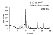
- FIG. 2 is a graph showing the X-ray diffraction pattern of the solid electrolyte obtained in Example 4.
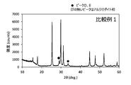
- FIG. 3 is a graph showing the X-ray diffraction pattern of the solid electrolyte obtained in Comparative Example 1.
- the solid electrolyte of the present invention contains at least a lithium (Li) element, a phosphorus (P) element, a sulfur (S) element, a halogen (X) element and an oxygen (O) element.
- the solid electrolyte of the present invention is typically a sulfide solid electrolyte.
- the solid electrolyte of the present invention containing these elements is preferably a crystalline compound.
- the crystalline compound is a substance in which a diffraction peak due to a crystalline phase is observed when measured by an X-ray diffraction method (hereinafter, also referred to as “XRD”). It is particularly preferable that the solid electrolyte contains a crystal phase having an argylodite-type crystal structure, because the lithium ion conductivity of the solid electrolyte can be enhanced.
- Diffraction peaks characteristic of ⁇ 1.0 °, 30.0 ° ⁇ 1.0 °, 30.9 ° ⁇ 1.0 ° and 44.3 ° ⁇ 1.0 ° are shown.
- 2 ⁇ 47.2 ° ⁇ 1.0 °, 51.7 ° ⁇ 1.0 °, 58.3 ° ⁇ 1.0 °, depending on the element species constituting the solid electrolyte.
- 60.7 ° ⁇ 1.0 °, 61.5 ° ⁇ 1.0 °, 70.4 ° ⁇ 1.0 ° and 72.6 ° ⁇ 1.0 ° may show characteristic diffraction peaks. be.
- the data of PDF No. 00-034-0688 can be used.
- the molar ratio (X / P) of the halogen (X) element to the phosphorus (P) element is set to a relatively high value.
- the molar ratio (X / P) is preferably set to a value larger than 1.0 and smaller than 2.4.
- the solid electrolyte having a molar ratio (X / P) set in this range and having an XRD peak described later has excellent battery characteristics when used in a solid-state battery while maintaining satisfactory lithium ion conductivity. Will be shown.
- the molar ratio (X / P) is preferably 1.2 or more, and more preferably 1.4 or more.
- the molar ratio (X / P) is, for example, preferably 2.2 or less, more preferably 2.0 or less, and even more preferably 1.6 or less.
- the molar ratio (X / P) can be measured, for example, by ICP emission spectroscopic measurement.
- the detailed description of the ICP emission spectroscopic measurement can be the same as that described in Examples described later, and thus the description thereof is omitted here.
- halogen (X) element which is one of the elements constituting the solid electrolyte, include a fluorine (F) element, a chlorine (Cl) element, a bromine (Br) element, and an iodine (I) element. ..
- the halogen (X) element may be one of these elements, or may be a combination of two or more.
- the solid electrolyte may contain at least a chlorine (Cl) element as a halogen (X) element, and bromine, from the viewpoint that the algyrodite type crystal structure described later is easily generated by the solid phase reaction and the lithium ion conductivity is enhanced. It may contain (Br) element and chlorine (Cl) element.
- the solid electrolyte may contain at least an iodine (I) element as a halogen (X) element, and even if the halogen (X) element is an iodine (I) element. good.
- the solid electrolyte contains bromine (Br) element and chlorine (Cl) element as halogen (X) element, bromine (Br) element with respect to the total number of moles of bromine (Br) element and chlorine (Cl) element.
- the ratio of Br / (Br + Cl) is, for example, preferably 0.2 or more, more preferably 0.3 or more, and even more preferably 0.4 or more.
- the value of Br / (Br + Cl) is preferably, for example, 0.8 or less, more preferably 0.7 or less, and even more preferably 0.6 or less.
- bromine (Br) While the introduction of bromine (Br) can easily form an algyrodite type crystal structure, bromine (Br) has a larger ionic radius than chlorine (Cl) and sulfur (S), so that it is a halogen solid in the algyrodite type crystal structure. It is thought that the amount of dissolution will decrease. Therefore, by appropriately adjusting Br / (Br + Cl) as described above, a large amount of halogen elements can be dissolved in the algyrodite type crystal structure while easily forming the algyrodite type crystal structure. As a result, the lithium ion conductivity of the solid electrolyte can be further enhanced. An increase in the amount of halogen solid solution in the algyrodite type crystal structure corresponds to a decrease in the occupancy rate of lithium sites in the crystal structure. It is considered that this improves the lithium ion conductivity.
- the solid electrolyte of the present invention exhibits an X-ray diffraction pattern different from that of the solid electrolytes known so far when measured by XRD.
- “having a peak” means having a peak top within a predetermined range of 2 ⁇ . Further, the “peak top” means the apex of the peak whose intensity shows the maximum value.
- the peaks A, B, and C are not diffraction peaks derived from an argylodite-type crystal structure, but diffraction peaks derived from a substance having another crystal structure. This substance reduces the interfacial resistance between the solid electrolyte and the active material, and when the solid electrolyte of the present invention is used for a solid battery, the solid battery may exhibit excellent battery characteristics.
- the solid electrolyte in which the peaks A, B and C are observed in the X-ray diffraction pattern measured by XRD is suitably produced by the method described later.
- the solid electrolyte produced also contains the oxygen (O) element due to the fact that the compound containing the oxygen (O) element is used as the raw material. That is, the solid electrolyte of the present invention contains an oxygen (O) element in addition to containing a lithium (Li) element, a phosphorus (P) element, a sulfur (S) element, and a halogen (X) element.
- the state of existence of the oxygen (O) element in the solid electrolyte is not clear at this time.
- the present inventor states that (i) the oxygen (O) element is contained in the above-mentioned substances derived from peak A, peak B and peak C, or (ii) algyrodite. It is speculated that it is either substituted with the element sulfur (S) in the type crystal structure, or both (i) and (ii).
- the solid state battery exhibits excellent battery characteristics when the solid electrolyte of the present invention is used for the solid state battery due to the substances derived from the peak A, peak B and peak C. it is conceivable that. Although it is speculative as to what this substance is, the present inventor suspects that this substance is lithium phosphate (Li 3 PO 4 ) in consideration of the suitable manufacturing method of the solid electrolyte described later. thinking.
- Li 3 PO 4 lithium phosphate
- One of the problems with solid-state batteries is that when a non-sulfide active material and a sulfide solid electrolyte come into contact with each other and react with each other, a high resistance substance is generated at the interface, thereby increasing the interface resistance of the battery. Are known.
- lithium phosphate When lithium phosphate is present in the solid electrolyte, it acts as an auxiliary agent to suppress the formation of high resistance while ensuring the contact between the active material and the sulfide solid electrolyte, and the solid electrolyte and the active material It is believed that the interfacial resistance between them will be reduced and the solid-state battery will exhibit excellent battery characteristics.
- lithium phosphate itself has lithium ion conductivity, when lithium phosphate is present between the sulfide solid electrolyte particles, it contributes to the improvement of the lithium ion conductivity of the solid electrolyte itself. Conceivable.
- fine particles of lithium phosphate particles are uniformly dispersed in a fixed amount of solid electrolyte particles.
- a preferred method is to precipitate lithium phosphate as a by-product in the solid phase reaction to form a solid electrified-lithium phosphate composite, as in the method for producing a solid electrolyte described below. According to this method, fine lithium phosphate particles can be uniformly dispersed among the solid electrolyte particles.
- the mixed anion effect caused by the replacement of the sulfur (S) element with the oxygen (O) element causes the solid electrolyte to maintain satisfactory lithium ion conductivity while maintaining the solid electrolyte. Is considered to exhibit excellent battery characteristics when the solid-state battery is used.
- lithium halide has high crystallinity and hardness as compared with other raw materials, so that uniform dispersion by mechanical mixing is difficult. As a result, it is not easy to dissolve a sufficient amount of halogen in the algyrodite type crystal structure by solid phase reaction, and unreacted lithium halide may remain as a heterogeneous phase in some cases.
- the ratio of lithium halide in the raw material is increased, the amount of lithium sulfide is relatively small, and the ratio of the sulfur (S) element as a whole decreases. Due to this, the Li 3 PS 4 structure collapses before halogen is taken in, and it changes to a stable structure such as Li 4 P 2 S 7 structure or Li 4 P 2 S 6 structure, which is solid. The insoluble halogen remains as a heterogeneous phase called lithium halide.
- the molar ratio (O / P) of the oxygen (O) element to the phosphorus (P) element may be, for example, greater than 0, greater than 0.11, or greater than 0.17. It may be large and may be larger than 0.19. On the other hand, the molar ratio (O / P) may be, for example, smaller than 0.5, 0.47 or less, or 0.45 or less. Since the solid electrolyte of the present invention has the molar ratio (O / P), excellent battery characteristics can be exhibited when the solid electrolyte is used in a solid battery.
- the molar amount of the oxygen (O) element in the molar ratio (O / P) can be measured by, for example, an inert gas melting-infrared absorption method or gas chromatography. Among them, the inert gas melting-infrared absorption method is widely used because of its simplicity and high accuracy.
- the molar amount of P element is measured by ICP emission spectroscopic measurement.
- the presence of the above-mentioned substances showing peaks A, B and C contributes to the solid-state battery exhibiting excellent battery characteristics.
- the ratio of the I a with respect to the I M are, for example, It is preferably less than 0.03, more preferably 0.025 or less, and even more preferably 0.02 or less.
- Diffraction peak intensity of XRD since approximately proportional to the amount of the substance, that I A / I M is in the range of above, the abundance of different phase other than the crystal phase having a Arujirodaito type crystal structure, It means that it is relatively lower than the abundance of the crystal phase having an algyrodite type crystal structure.
- I A / I M may be appropriately determined within a range in which the desired effects of the present invention is exerted, it is preferably greater than 0, more preferably 0.005.
- peak B and peak C are as described below for the same reason as described for peak A.
- the intensity of the peak B and I B when the intensity of the peak M was I M, it is preferable that a ratio of the I B with respect to the I M (I B / I M) is 0.025 or less, 0 It is more preferably 0.02 or less, and even more preferably 0.015 or less.
- the intensity of the peak C and I C when the intensity of the peak M was I M, the ratio of the I C relative to the I M (I C / I M) is preferably at 0.012 or less, 0 It is more preferably 0.011 or less, and even more preferably 0.01 or less.
- I B / I M and I C / I M can be appropriately determined in the range of desired effects of the present invention is exerted, it is preferably greater than 0 with respect to I B / I M, among others 0 is preferably .002 or higher, preferably greater than 0 with respect to I C / I M, is preferably Among them, 0.001 or more.
- I A, I B, I C and I M is except for the portion corresponding to the background of the area of the peak A, B, C and M in the X-ray diffraction pattern as measured by XRD (i.e. integrated intensity) It is a thing. Further, in the present invention, CuK ⁇ 1 ray is used as a radiation source for all XRD measurements.
- the peak A is present two or more, there may, among them the two or more if at least one I A of the peak present the two or more satisfies a predetermined ratio described above it is preferable to satisfy the predetermined ratio I a is described above showing the maximum intensity of the peak, it is particularly preferable that all of the I a of the two or more peaks satisfies a predetermined ratio described above.
- I B which is the same for I C and I M.
- the solid electrolyte in which the peak D is observed tends to have lower lithium ion conductivity than the solid electrolyte in which the peak is not observed. Therefore, in view of enhancing the lithium ion conductive solid electrolyte, the intensity of a peak D when the I D, such that the ratio of I D for I M (I D / I M ) is preferably less than 0.21 It is preferable to control the existence state of the crystal phase of the solid electrolyte.
- I D / I M is more preferably 0.18 or less, more preferably 0.16 or less.
- I D / I M is advantageous from the viewpoint of improving the smaller the lithium ion conductivity is smaller, may be larger than 0 is zero ideally.
- This peak E is also not derived from the algyrodite type crystal structure.
- a solid electrolyte in which a peak E is observed tends to have lower lithium ion conductivity than a solid electrolyte in which the peak is not observed. Therefore, in view of enhancing the lithium ion conductive solid electrolyte, the intensity of peak E when the I E, the ratio (I E / I M) are preferred I E for I M such that 0.30 It is preferable to control the existence state of the crystal phase of the solid electrolyte.
- I E / I M is more preferably 0.28 or less, more preferably 0.25 or less, even more preferably 0.16 or less, even 0.13 or less. I E / I M is advantageous from the viewpoint of improving the smaller the lithium ion conductivity smaller, ideally zero.
- the solid electrolyte of the present invention contains a lithium (Li) element, a phosphorus (P) element, a sulfur (S) element, and a halogen (X) element, and in some cases, contains an oxygen (O) element.
- Li lithium
- P phosphorus
- S sulfur
- X halogen
- Elements other than these elements may be contained.
- part of the lithium (Li) element may be replaced with another alkali metal element
- part of the phosphorus (P) element may be replaced with another punictogen element
- part of the sulfur (S) element may be replaced with another chalcogen. It can be replaced with an element.
- the solid electrolyte of the present invention is unavoidable as long as the effects of the present invention are not impaired, in addition to the lithium (Li) element, the phosphorus (P) element, the sulfur (S) element, the halogen (X) element, and the oxygen (O) element. It is permissible to contain impurities.
- the content of the unavoidable impurities can be, for example, less than 5 mol% at the highest, preferably less than 3 mol%, and particularly preferably less than 1 mol% from the viewpoint of having a low effect on the performance of the solid electrolyte.
- the solid electrolyte of the present invention has lithium ion conductivity in the solid state.
- the solid electrolyte preferably has a lithium ion conductivity of 0.5 mS / cm or more at room temperature, that is, 25 ° C., and preferably has a lithium ion conductivity of 1.5 mS / cm or more, particularly 2.5 mS / cm. It is preferable to have lithium ion conductivity of cm or more. Lithium ion conductivity can be measured using the method described in Examples described below.
- the method for producing a solid electrolyte in the present invention is a step of preparing a raw material composition containing at least a lithium (Li) element, a phosphorus (P) element, a sulfur (S) element, a halogen (X) element and an oxygen (O) element. And a step of firing the raw material composition.
- the solid electrolyte is preferably produced by a solid phase reaction by subjecting a raw material composition containing a predetermined element to firing.
- the raw material composition can be obtained by mixing a predetermined raw material.
- the raw material is a substance containing an element constituting a solid electrolyte, and more specifically, a compound containing a lithium (Li) element, a compound containing a sulfur (S) element, and a phosphorus (P) element. It is a compound containing a compound, a compound containing a halogen (X) element, and a compound containing an oxygen (O) element.
- Examples of the compound containing a lithium (Li) element include lithium compounds such as lithium sulfide (Li 2 S), lithium oxide (Li 2 O) and lithium carbonate (Li 2 CO 3 ), and lithium metal alone. Can be done.
- Examples of the compound containing a sulfur (S) element include phosphorus sulfide such as nirin trisulfide (P 2 S 3 ) and diphosphorus pentasulfide (P 2 S 5 ). Further, as a compound containing a sulfur (S) element, sulfur (S) alone can be used.
- Examples of the compound containing a phosphorus (P) element include phosphorus sulfide such as nirin trisulfide (P 2 S 3 ) and diphosphorus pentasulfide (P 2 S 5 ), and phosphorus such as sodium phosphate (Na 3 PO 4 ). Examples include compounds and phosphorus alone.
- an X (halogen) element one or more elements selected from the group consisting of a fluorine (F) element, a chlorine (Cl) element, a bromine (Br) element and an iodine (I) element.
- a compound with two or more kinds of elements, or a compound in which oxygen or sulfur is further bonded to the compound can be mentioned.
- LiF, LiCl, LiBr, lithium halide such as LiI, PF 3, PF 5, PCl 3, PCl 5, POCl 3, PBr 3, POBr 3, PI 3, P 2 Cl 4, P 2 Phosphorus pentachloride such as I 4 , SF 2 , SF 4 , SF 6 , S 2 F 10 , SCl 2 , S 2 Cl 2 , S 2 Br 2, etc.
- Examples of the compound containing an oxygen (O) element include the above-mentioned lithium oxide (Li 2 O), lithium carbonate (Li 2 CO 3 ), sodium phosphate (Na 3 PO 4 ), POCl 3 and the like.
- an attritor for example, an attritor, a paint shaker, a planetary ball mill, a ball mill, a bead mill, a homogenizer, or the like can be used.
- the amount added when mixing each raw material is appropriately adjusted so as to satisfy the composition of the target solid electrolyte.
- the obtained raw material composition is subjected to firing to cause a solid-phase reaction to obtain a solid electrolyte containing a crystal phase having an argylodite-type crystal structure.
- a firing atmosphere for example, an inert gas atmosphere such as an argon atmosphere or a nitrogen atmosphere, and a hydrogen sulfide atmosphere can be used.
- an inert gas atmosphere which is an atmosphere in which oxygen is easily taken into the solid electrolyte.
- the firing temperature is preferably, for example, 300 ° C. or higher, more preferably 350 ° C. or higher, and even more preferably 400 ° C. or higher, from the viewpoint of reliably causing a solid-phase reaction of the raw material composition.
- the firing temperature is preferably, for example, 700 ° C. or lower, more preferably 600 ° C. or lower, and even more preferably 550 ° C. or lower, in consideration of industrial productivity and economic efficiency.
- the firing time is not critical and may be any time as long as a solid electrolyte having the desired composition can be obtained. Specifically, it is preferable that the firing time is such that a solid-phase reaction of the raw material composition sufficiently occurs.
- the firing time may be, for example, 30 minutes or more, 2 hours or more, or 3 hours or more. On the other hand, the firing time may be, for example, 10 hours or less, or 5 hours or less.
- the fired product may be crushed and crushed as needed, and further classified as needed.
- a crusher such as a planetary ball mill, a vibration mill, a rolling mill, a kneader, or the like.
- the solid electrolyte thus obtained can be used alone or in combination with other solid electrolytes.
- the solid electrolyte preferably has a D 50 by volume particle size distribution obtained by measuring by a laser diffraction scattering particle size distribution measurement method is 0.1 ⁇ m or more 250 ⁇ m or less.
- the D 50 of the solid electrolyte is 0.1 ⁇ m or more, the surface area of the solid electrolyte can be suppressed from being excessively increased, the increase in resistance can be suppressed, and the mixing with the active material can be facilitated.
- the D 50 of the solid electrolyte is 250 ⁇ m or less, for example, when the solid electrolyte and another solid electrolyte are used in combination, it becomes easy to close-pack both of them.
- the D 50 of the solid electrolyte is preferably, for example, 0.3 ⁇ m or more, and particularly preferably 0.5 ⁇ m or more.
- the D 50 of the solid electrolyte is preferably, for example, 150 ⁇ m or less, particularly preferably 70 ⁇ m or less, and particularly preferably 50 ⁇ m or less.
- the solid electrolyte of the present invention can be used as a material constituting the solid electrolyte layer, the positive electrode layer or the negative electrode layer.
- the solid electrolyte of the present invention can be used for a battery having a positive electrode layer, a negative electrode layer, and a solid electrolyte layer between the positive electrode layer and the negative electrode layer. That is, the solid electrolyte can be used for so-called solid-state batteries. More specifically, it can be used for a lithium solid-state battery.
- the lithium solid-state battery may be a primary battery or a secondary battery.
- the shape of the battery is not particularly limited, and for example, a laminated type, a cylindrical type, a square type, or the like can be adopted.
- the "solid-state battery” includes, for example, 50% by mass or less, 30% by mass or less, 10% by mass or less of a liquid substance or a gel-like substance as an electrolyte, in addition to a solid-state battery containing no liquid substance or a gel-like substance as an electrolyte. Also includes aspects.
- the solid electrolyte layer contains the solid electrolyte of the present invention
- the solid electrolyte layer can be used, for example, by dropping a slurry consisting of a solid electrolyte, a binder and a solvent onto a substrate and scraping it off with a doctor blade or the like, the substrate and the slurry. It can be manufactured by a method of cutting with an air knife after contacting the solid, a method of forming a coating film by a screen printing method or the like, and then heat-drying to remove the solvent. Alternatively, it can also be produced by appropriately processing a powdered solid electrolyte after making it into a compact by pressing or the like.
- the thickness of the solid electrolyte layer is typically preferably 5 ⁇ m or more and 300 ⁇ m or less, and more preferably 10 ⁇ m or more and 100 ⁇ m or less, in view of the balance between short circuit prevention and volume volume density.
- the solid electrolyte of the present invention can also be used together with an active material to form an electrode mixture.
- the proportion of the solid electrolyte in the electrode mixture is typically 10% by mass or more and 50% by mass or less.
- the electrode mixture may contain other materials such as a conductive agent and a binder, if necessary.
- a positive electrode layer and a negative electrode layer can be prepared by mixing an electrode mixture and a solvent to prepare a paste, applying the paste onto a current collector such as an aluminum foil, and drying the paste.
- the positive electrode material used as the positive electrode active material of the lithium ion battery can be appropriately used.
- a positive electrode active material containing lithium specifically, a spinel-type lithium transition metal oxide, a lithium metal oxide having a layered structure, and the like can be mentioned.
- the positive electrode material may contain a conductive material, or may contain other materials.
- the negative electrode material constituting the negative electrode layer the negative electrode material used as the negative electrode active material of the lithium ion battery can be appropriately used.
- the solid electrolyte of the present invention is electrochemically stable, graphite, artificial graphite, which is a material that charges and discharges at a low potential (about 0.1 V vs. Li + / Li) comparable to lithium metal or lithium metal, Carbon-based materials such as natural graphite and non-graphitizable carbon (hard carbon) can be used as the negative electrode material. Thereby, the energy density of the solid-state battery can be greatly improved. Further, silicon or tin, which is promising as a high-capacity material, can also be used as an active material.
- the electrolytic solution reacts with the active material during charging and discharging, and the surface of the active material is corroded, so that the battery characteristics are significantly deteriorated.
- the solid electrolyte of the present invention is used instead of the electrolytic solution and silicon or tin is used as the negative electrode active material, the above-mentioned corrosion reaction does not occur, so that the durability of the battery can be improved.
- the negative electrode material may also contain a conductive material in addition to the negative electrode active material, or may contain other materials.
- the powder and the lithium bromide (LiBr) powder were weighed so that the total amount was 5 g. 10 mL of heptane was added to these powders to prepare a slurry. This slurry was placed in a planetary ball mill device. Using ZrO 2 balls having a diameter of 10mm as the media. The operating conditions of the ball mill device were 100 rpm, and mixing was performed for 10 hours.
- the resulting mixture was calcined at 500 ° C. for 4 hours under an argon atmosphere. In this way, a solid electrolyte was obtained.
- the lithium ion conductivity of the obtained solid electrolyte was measured based on Evaluation 4 described later, it was 3.6 mS / cm.
- Example 2 to 4 Lithium sulfide (Li 2 S) powder, lithium oxide (Li 2 O) powder, diphosphorus pentasulfide (P 2 S 5 ) powder, and lithium chloride (LiCl) so as to have the preparation composition shown in Table 1 below. ) Powder and lithium bromide (LiBr) powder were mixed. A solid electrolyte was obtained in the same manner as in Example 1 except for the above. When the lithium ion conductivity of the obtained solid electrolyte was measured based on Evaluation 4 described later, 3.8 mS / cm and 3.4 mS / cm and 2.9 mS / in the order of Example 2 to Example 4. It was cm.
- Lithium oxide (Li 2 O) powder was not used in this comparative example.
- Lithium sulfide (Li 2 S) powder, diphosphorus pentasulfide (P 2 S 5 ) powder, lithium chloride (LiCl) powder, and lithium bromide (LiBr) so as to have the preparation composition shown in Table 1 below.
- the powder was mixed.
- a solid electrolyte was obtained in the same manner as in Example 1 except for the above. When the lithium ion conductivity of the obtained solid electrolyte was measured based on Evaluation 4 described later, it was 3.1 mS / cm.
- This comparative example is an example of producing a solid electrolyte corresponding to the solid electrolyte of Non-Patent Document 1.
- LiBr) powder was mixed.
- a solid electrolyte was obtained in the same manner as in Example 1 except for the above. When the lithium ion conductivity of the obtained solid electrolyte was measured based on Evaluation 4 described later, it was 1.1 mS / cm.
- This comparative example is an example of producing a solid electrolyte having a high molar ratio (X / P).
- Powder and lithium bromide (LiBr) powder were mixed.
- a solid electrolyte was obtained in the same manner as in Example 1 except for the above. When the lithium ion conductivity of the obtained solid electrolyte was measured based on Evaluation 4 described later, it was 1.8 mS / cm.
- This comparative example is an example of producing a solid electrolyte having a low molar ratio (X / P).
- Powder and lithium bromide (LiBr) powder were mixed.
- a solid electrolyte was obtained in the same manner as in Example 1 except for the above. When the lithium ion conductivity of the obtained solid electrolyte was measured based on Evaluation 4 described later, it was 1.0 mS / cm.
- the molar amounts of P and X in this measurement solution were measured by a sequential ICP-OES apparatus (SPS3500DD manufactured by Hitachi High-Tech Science Co., Ltd.).
- the calibration curve solution was prepared using a 1000 mg / L standard solution for ICP measurement for phosphorus and a 1000 mg / L standard solution for ion chromatograph for chlorine and bromine. The measurement was performed twice for each sample, and the ratio of each element was determined by averaging the two measured values.
- the molar amount of O was calculated by the Infrared Gas Melting-Infrared Absorption Method.
- the solid electrolyte powder was weighed in an argon atmosphere and collected in nickel capsules for gas analysis.
- a nickel capsule was sealed so that the powder did not come into contact with the outside air, and the capsule was attached to an oxygen-nitrogen hydrogen analyzer (EMGA930 manufactured by HORIBA, Ltd.) equipped with a desulfurization mechanism to measure the molar amount of O.
- EMGA930 manufactured by HORIBA, Ltd.
- a metal auxiliary agent nickel was added for desulfurization. Two measurements were made on each sample and the percentage of oxygen was determined by averaging the two measurements.
- the measurement conditions were no exposure to the atmosphere, scanning axis: 2 ⁇ / ⁇ , scanning range: 10 ° or more and 140 ° or less, step width 0.01 °, and scanning speed 2 ° / min.
- the X-ray source was CuK ⁇ 1 ray using a Johanson type crystal.
- a one-dimensional detector was used for detection. The measurement was carried out so that the intensity of 21.3 ⁇ 1.0 ° was 100 or more and 700 or less. Further, it was carried out so that the maximum peak intensity of 10 ° or more and 140 ° or less was a count number of 1000 or more.
- the Rigaku program "PDXL" was used to calculate the peak intensity. The calculation was performed by performing automatic data processing and reading the integrated intensity of the peak corresponding to each angle range from the obtained peak list. As the setting condition, the "sigma cut value of the peak search" was set to 3.0, and the other processing was performed under the initial setting condition.
- the negative electrode mixture powder was prepared by mixing a negative electrode active material powder and a solid electrolyte powder made of graphite in a dairy pot at a mass ratio of 64:36. D 50 by volume particle size distribution of the graphite was 20 [mu] m.
- the positive electrode mixture powder is prepared by mixing a positive electrode active material powder, a solid electrolyte powder, and a conductive agent (VGCF (registered trademark)) powder in a dairy pot at a mass ratio of 60:37: 3.
- VGCF conductive agent
- NCM523 was used as the positive electrode active material powder described here.
- NCM523 is a powder represented by the composition formula: LiNi 0.5 Co 0.2 Mn 0.3 O 2 .
- D 50 by volume particle size distribution of NCM523 was 2 [mu] m.
- the solid-state battery was set in a charging / discharging device in which the environmental temperature was set to 25 ° C., and the battery was allowed to stand until the battery temperature reached the environmental temperature. The battery was charged and discharged with 1 mA as 1 C. First, constant current and constant voltage charging was performed at 0.1 C to 4.5 V to obtain an initial charge capacity. Next, a constant current discharge was performed at 0.1 C to 2.5 V to obtain an initial discharge capacity. From the values of the initial charge capacity and the initial discharge capacity, it was confirmed that the battery was operating as a solid-state battery.
- DC resistance (DC-IR) measurement was performed.
- the conditions for direct current resistance (DC-IR) measurement were a measurement current of 5 mA and a measurement time of 10 seconds. The values of the obtained DC resistance are shown in Table 1.
- the lithium ion conductivity of the solid electrolytes obtained in Examples and Comparative Examples was measured by the following method. Each solid electrolyte is uniaxially pressure-molded by applying a load of about 6 t / cm 2 in a glove box replaced with a sufficiently dried argon gas (dew point -60 ° C or lower), and has a diameter of 10 mm and a thickness of about 1 mm or more. A sample for measuring lithium ion conductivity consisting of 8 mm pellets was prepared. The lithium ion conductivity was measured using Solartron 1255B manufactured by Toyo Corporation. The measurement conditions were an AC impedance method with a temperature of 25 ° C., a frequency of 100 Hz to 1 MHz, and an amplitude of 100 mV.
- the charged composition shown in Table 1 is a composition assuming that the oxygen (O) element is replaced with the sulfur (S) element in the algyrodite type crystal structure.
- the solid electrolyte obtained in each example can lower the DC resistance of the battery as compared with the solid electrolyte of the comparative example. Further, as shown in FIGS. 1 and 2, it was confirmed that the solid electrolytes obtained in Examples 2 and 4 had a crystal phase having an algyrodite type crystal structure. Further, although not shown, the solid electrolytes obtained in Examples 1 and 3 also have the same crystal phase as the solid electrolytes obtained in Examples 2 and 4, and the crystal phase of the algyrodite type crystal structure, and the peaks A and B. And it was confirmed that it had a crystal phase derived from C.
- a solid electrolyte capable of obtaining excellent battery characteristics when used in a solid battery while maintaining lithium ion conductivity.
Landscapes
- Chemical & Material Sciences (AREA)
- General Chemical & Material Sciences (AREA)
- Electrochemistry (AREA)
- Chemical Kinetics & Catalysis (AREA)
- Engineering & Computer Science (AREA)
- Manufacturing & Machinery (AREA)
- Inorganic Chemistry (AREA)
- General Physics & Mathematics (AREA)
- Condensed Matter Physics & Semiconductors (AREA)
- Physics & Mathematics (AREA)
- Materials Engineering (AREA)
- Organic Chemistry (AREA)
- Conductive Materials (AREA)
- Secondary Cells (AREA)
Abstract
This solid electrolyte comprises a crystal phase that has an argyrodite crystal structure, while containing at least elemental lithium (Li), elemental phosphorus (P), elemental sulfur (S), elemental halogen (X) and elemental oxygen (O). With respect to this solid electrolyte, the molar ratio of the elemental halogen (X) to the elemental phosphorus (P), namely X/P is more than 1.0 but less than 2.4, while the molar ratio of the elemental oxygen (O) to the elemental phosphorus (P), namely O/P is more than 0 but less than 0.5. The X-ray diffraction pattern of this solid electrolyte as determined by an X-ray diffraction device (XRD) using a CuKα 1 ray has a peak A within the range of from 2θ = 21.6° to 2θ = 22.6°, a peak B within the range of from 2θ = 22.7° to 2θ = 23.7°, and a peak C within the range of from 2θ = 35.8° to 2θ = 36.8°.
Description
本発明は固体電解質に関する。また本発明は、該固体電解質を含む電極合剤及び電池に関する。
The present invention relates to a solid electrolyte. The present invention also relates to an electrode mixture containing the solid electrolyte and a battery.
リチウムイオン伝導性を有する固体電解質として種々の硫化物材料が知られている。例えば非特許文献1には、酸素をドープしたLi6PS5Br、すなわちLi6PS5-XOXBr(0≦x≦1)を固体電解質として用いることが記載されている。同文献の記載によれば、Li6PS5Brに酸素をドープすることで、デンドライトの発生が抑制され、電気化学的安定性及び化学的安定性が向上するとされている。また、同文献の記載によれば、Li6PS5-XOXBrは、主たる結晶相がアルジロダイト相であり、ドープされた酸素は一定量であればアルジロダイト相中の硫黄サイトに置換され、前記のような効果が得られるとされている。更に置換できる酸素の量を超えてドープすると不純物であるリン酸リチウムや臭化リチウムが生成するとともに、イオン伝導率が低下することが記載されており、不純物であるリン酸リチウムや臭化リチウムの生成は忌避されている。
Various sulfide materials are known as solid electrolytes having lithium ion conductivity. For example, Non-Patent Document 1 describes that oxygen-doped Li 6 PS 5 Br, that is, Li 6 PS 5-X O X Br (0 ≦ x ≦ 1) is used as a solid electrolyte. According to the description in the same document, by doping Li 6 PS 5 Br with oxygen, the generation of dendrites is suppressed, and the electrochemical stability and the chemical stability are improved. Further, according to the description of the document, Li 6 PS 5-X O X Br is main crystal phase is Arujirodaito phase, doped oxygen is replaced by sulfur sites in Arujirodaito phase if a certain amount, It is said that the above effects can be obtained. Furthermore, it has been described that when the amount of oxygen that can be replaced is excessively doped, lithium phosphate and lithium bromide, which are impurities, are generated, and at the same time, the ionic conductivity is lowered. Generation is repelled.
例えば、上述した非特許文献1のように、リチウムイオン伝導性の高い固体電解質について種々の検討がなされている。一方、近年では、リチウムイオン伝導性を維持しつつ、固体電池に用いた場合に優れた電池特性を得ることが可能な固体電解質が求められている。したがって本発明の課題は、リチウムイオン伝導性を維持しつつ、固体電池に用いた場合に優れた電池特性を得ることが可能な固体電解質を提供することにある。
For example, as in Non-Patent Document 1 described above, various studies have been made on solid electrolytes having high lithium ion conductivity. On the other hand, in recent years, there has been a demand for a solid electrolyte capable of obtaining excellent battery characteristics when used in a solid-state battery while maintaining lithium ion conductivity. Therefore, an object of the present invention is to provide a solid electrolyte capable of obtaining excellent battery characteristics when used in a solid state battery while maintaining lithium ion conductivity.
本発明は、少なくともリチウム(Li)元素、リン(P)元素、硫黄(S)元素、ハロゲン(X)元素及び酸素(O)元素を含有し、
アルジロダイト型結晶構造を有する結晶相を含み、
リン(P)元素に対するハロゲン(X)元素のモル比(X/P)が1.0より大きく2.4より小さく、
リン(P)元素に対する酸素(O)元素のモル比(O/P)が0より大きく0.5より小さく、
CuKα1線を用いたX線回折装置により測定されるX線回折パターンにおいて、2θ=21.6°以上22.6°以下の範囲にピークAを有し、2θ=22.7°以上23.7°以下の範囲にピークBを有し、2θ=35.8°以上36.8°以下の範囲にピークCを有する、固体電解質を提供するものである。 The present invention contains at least lithium (Li) element, phosphorus (P) element, sulfur (S) element, halogen (X) element and oxygen (O) element.
Includes a crystalline phase with an argyrodite-type crystal structure,
The molar ratio (X / P) of the halogen (X) element to the phosphorus (P) element is greater than 1.0 and less than 2.4.
The molar ratio (O / P) of the oxygen (O) element to the phosphorus (P) element is greater than 0 and less than 0.5.
In the X-ray diffraction pattern measured by an X-ray diffractometer using CuKα1 ray, the peak A is in the range of 2θ = 21.6 ° or more and 22.6 ° or less, and 2θ = 22.7 ° or more and 23.7 °. It provides a solid electrolyte having a peak B in the range of ° or less and a peak C in the range of 2θ = 35.8 ° or more and 36.8 ° or less.
以下本発明を、その好ましい実施形態に基づき説明する。本発明の固体電解質は、少なくともリチウム(Li)元素、リン(P)元素、硫黄(S)元素、ハロゲン(X)元素及び酸素(O)元素を含有するものである。本発明の固体電解質は、典型的には硫化物固体電解質である。これらの元素を含有する本発明の固体電解質は結晶性化合物であることが好ましい。結晶性化合物とは、X線回折法(以下「XRD」ともいう。)による測定を行った場合に、結晶相に起因する回折ピークが観察される物質のことである。固体電解質は特にアルジロダイト型結晶構造を有する結晶相を含むことが、固体電解質のリチウムイオン伝導性を高め得る点から好ましい。
Hereinafter, the present invention will be described based on its preferred embodiment. The solid electrolyte of the present invention contains at least a lithium (Li) element, a phosphorus (P) element, a sulfur (S) element, a halogen (X) element and an oxygen (O) element. The solid electrolyte of the present invention is typically a sulfide solid electrolyte. The solid electrolyte of the present invention containing these elements is preferably a crystalline compound. The crystalline compound is a substance in which a diffraction peak due to a crystalline phase is observed when measured by an X-ray diffraction method (hereinafter, also referred to as “XRD”). It is particularly preferable that the solid electrolyte contains a crystal phase having an argylodite-type crystal structure, because the lithium ion conductivity of the solid electrolyte can be enhanced.
アルジロダイト型結晶構造とは化学式:Ag8GeS6で表される鉱物に由来する化合物群が有する結晶構造である。本発明の固体電解質がアルジロダイト型結晶構造の結晶相を有しているか否かは、XRDによる測定などによって確認できる。例えばCuKα1線を用いたXRDによって測定される回折パターンにおいて、アルジロダイト型結晶構造の結晶相は、2θ=15.3°±1.0°、17.7°±1.0°、25.2°±1.0°、30.0°±1.0°、30.9°±1.0°及び44.3°±1.0°に特徴的な回折ピークを示す。また、固体電解質を構成する元素種によっては、前記回折ピークに加えて、2θ=47.2°±1.0°、51.7°±1.0°、58.3°±1.0°、60.7°±1.0°、61.5°±1.0°、70.4°±1.0°及び72.6°±1.0°に特徴的な回折ピークを示す場合もある。アルジロダイト型結晶構造に由来する回折ピークの同定には、例えばPDF番号00-034-0688のデータを用いることができる。
The algyrodite type crystal structure is a crystal structure possessed by a group of compounds derived from a mineral represented by a chemical formula: Ag 8 GeS 6. Whether or not the solid electrolyte of the present invention has a crystal phase having an algyrodite type crystal structure can be confirmed by measurement by XRD or the like. For example, in the diffraction pattern measured by XRD using CuKα1 ray, the crystal phase of the argylodite type crystal structure is 2θ = 15.3 ° ± 1.0 °, 17.7 ° ± 1.0 °, 25.2 °. Diffraction peaks characteristic of ± 1.0 °, 30.0 ° ± 1.0 °, 30.9 ° ± 1.0 ° and 44.3 ° ± 1.0 ° are shown. In addition to the diffraction peak, 2θ = 47.2 ° ± 1.0 °, 51.7 ° ± 1.0 °, 58.3 ° ± 1.0 °, depending on the element species constituting the solid electrolyte. , 60.7 ° ± 1.0 °, 61.5 ° ± 1.0 °, 70.4 ° ± 1.0 ° and 72.6 ° ± 1.0 ° may show characteristic diffraction peaks. be. For the identification of the diffraction peak derived from the algyrodite type crystal structure, for example, the data of PDF No. 00-034-0688 can be used.
本発明の固体電解質においては、リン(P)元素に対するハロゲン(X)元素のモル比(X/P)が比較的高い値に設定されている。具体的にはモル比(X/P)が好ましくは1.0より大きく2.4より小さい値に設定されている。モル比(X/P)がこの範囲に設定されており、且つ後述するXRDピークを有する固体電解質は、満足すべきリチウムイオン伝導性を維持しつつ、固体電池に用いた場合に優れた電池特性を示すものとなる。この利点を一層顕著なものとする観点から、モル比(X/P)は例えば1.2以上であることが好ましく、1.4以上であることが一層好ましい。一方、前記モル比(X/P)は、例えば2.2以下であることが好ましく、2.0以下であることが一層好ましく、1.6以下であることがより一層好ましい。モル比(X/P)は、例えばICP発光分光測定によって測定することができる。なお、ICP発光分光測定の詳細な説明は、後述する実施例に記載の内容と同様とすることができるため、ここでの記載は省略する。
In the solid electrolyte of the present invention, the molar ratio (X / P) of the halogen (X) element to the phosphorus (P) element is set to a relatively high value. Specifically, the molar ratio (X / P) is preferably set to a value larger than 1.0 and smaller than 2.4. The solid electrolyte having a molar ratio (X / P) set in this range and having an XRD peak described later has excellent battery characteristics when used in a solid-state battery while maintaining satisfactory lithium ion conductivity. Will be shown. From the viewpoint of further enhancing this advantage, the molar ratio (X / P) is preferably 1.2 or more, and more preferably 1.4 or more. On the other hand, the molar ratio (X / P) is, for example, preferably 2.2 or less, more preferably 2.0 or less, and even more preferably 1.6 or less. The molar ratio (X / P) can be measured, for example, by ICP emission spectroscopic measurement. The detailed description of the ICP emission spectroscopic measurement can be the same as that described in Examples described later, and thus the description thereof is omitted here.
固体電解質を構成する元素の一つであるハロゲン(X)元素としては、例えば、フッ素(F)元素、塩素(Cl)元素、臭素(Br)元素、及びヨウ素(I)元素を挙げることができる。ハロゲン(X)元素は、これらの元素のうちの1種であってもよく、あるいは2種以上の組み合わせであってもよい。後述するアルジロダイト型結晶構造が固相反応によって生成しやすくなり、リチウムイオン伝導性が高まる観点から、固体電解質は、ハロゲン(X)元素として少なくとも塩素(Cl)元素を含有していてもよく、臭素(Br)元素及び塩素(Cl)元素を含有していてもよい。また、リチウムイオン伝導性をより高める観点から、固体電解質は、ハロゲン(X)元素として少なくともヨウ素(I)元素を含んでいてもよく、ハロゲン(X)元素がヨウ素(I)元素であってもよい。
Examples of the halogen (X) element, which is one of the elements constituting the solid electrolyte, include a fluorine (F) element, a chlorine (Cl) element, a bromine (Br) element, and an iodine (I) element. .. The halogen (X) element may be one of these elements, or may be a combination of two or more. The solid electrolyte may contain at least a chlorine (Cl) element as a halogen (X) element, and bromine, from the viewpoint that the algyrodite type crystal structure described later is easily generated by the solid phase reaction and the lithium ion conductivity is enhanced. It may contain (Br) element and chlorine (Cl) element. Further, from the viewpoint of further enhancing the lithium ion conductivity, the solid electrolyte may contain at least an iodine (I) element as a halogen (X) element, and even if the halogen (X) element is an iodine (I) element. good.
固体電解質がハロゲン(X)元素として臭素(Br)元素及び塩素(Cl)元素を含有する場合、臭素(Br)元素のモル数と塩素(Cl)元素のモル数の合計に対する臭素(Br)元素の割合、すなわちBr/(Br+Cl)の値は、例えば0.2以上であることが好ましく、0.3以上であることが更に好ましく、0.4以上であることが一層好ましい。一方、前記Br/(Br+Cl)の値は、例えば0.8以下であることが好ましく、0.7以下であることが更に好ましく、0.6以下であることが一層好ましい。
臭素(Br)の導入はアルジロダイト型結晶構造を容易に形成できる一方で、臭素(Br)は塩素(Cl)や硫黄(S)に比べてイオン半径が大きいため、アルジロダイト型結晶構造へのハロゲン固溶量が少なくなると考えられる。したがって、上述のとおりBr/(Br+Cl)を適切に調整することで、アルジロダイト型結晶構造を容易に生成しつつ、アルジロダイト型結晶構造により多くのハロゲン元素を固溶させることができる。その結果、固体電解質のリチウムイオン伝導性を一層高めることができる。アルジロダイト型結晶構造においてハロゲン固溶量が増加することは、結晶構造内のリチウムサイトの占有率が低下することに対応する。このことによってリチウムイオン伝導性が向上すると考えられる。 When the solid electrolyte contains bromine (Br) element and chlorine (Cl) element as halogen (X) element, bromine (Br) element with respect to the total number of moles of bromine (Br) element and chlorine (Cl) element. The ratio of Br / (Br + Cl) is, for example, preferably 0.2 or more, more preferably 0.3 or more, and even more preferably 0.4 or more. On the other hand, the value of Br / (Br + Cl) is preferably, for example, 0.8 or less, more preferably 0.7 or less, and even more preferably 0.6 or less.
While the introduction of bromine (Br) can easily form an algyrodite type crystal structure, bromine (Br) has a larger ionic radius than chlorine (Cl) and sulfur (S), so that it is a halogen solid in the algyrodite type crystal structure. It is thought that the amount of dissolution will decrease. Therefore, by appropriately adjusting Br / (Br + Cl) as described above, a large amount of halogen elements can be dissolved in the algyrodite type crystal structure while easily forming the algyrodite type crystal structure. As a result, the lithium ion conductivity of the solid electrolyte can be further enhanced. An increase in the amount of halogen solid solution in the algyrodite type crystal structure corresponds to a decrease in the occupancy rate of lithium sites in the crystal structure. It is considered that this improves the lithium ion conductivity.
本発明の固体電解質は、XRDによる測定を行った場合、これまでに知られている固体電解質とは異なるX線回折パターンを示す。具体的には、本発明の固体電解質は、CuKα1線を用いたXRDにより測定されるX線回折パターンにおいて、2θ=21.6°以上22.6°以下の範囲にピークAを有し、2θ=22.7°以上23.7°以下の範囲にピークBを有し、2θ=35.8°以上36.8°以下の範囲にピークCを有する。
ここで、「ピークを有する」とは、所定の2θの範囲内においてピークトップを有することを意味する。また、「ピークトップ」とは、強度が極大値を示すピークの頂点を意味する。 The solid electrolyte of the present invention exhibits an X-ray diffraction pattern different from that of the solid electrolytes known so far when measured by XRD. Specifically, the solid electrolyte of the present invention has a peak A in the range of 2θ = 21.6 ° or more and 22.6 ° or less in the X-ray diffraction pattern measured by XRD using CuKα1 ray, and 2θ. It has a peak B in the range of = 22.7 ° or more and 23.7 ° or less, and has a peak C in the range of 2θ = 35.8 ° or more and 36.8 ° or less.
Here, "having a peak" means having a peak top within a predetermined range of 2θ. Further, the “peak top” means the apex of the peak whose intensity shows the maximum value.
ピークAに関しては、2θ=21.6°以上22.6°以下の範囲にピークトップを有するピークが1個又は2個以上観察される。ピークBに関しては、2θ=22.7°以上23.7°以下の範囲にピークトップを有するピークが1個又は2個以上観察される。ピークCに関しては、2θ=35.8°以上36.8°以下の範囲にピークトップを有するピークが1個又は2個以上観察される。
XRDにより測定されるX線回折パターンにおいてピークA、ピークB及びピークCが観察され、且つ上述したモル比(X/P)を有する固体電解質は、満足すべきリチウムイオン伝導性を維持しつつ、固体電池に用いた場合に該固体電池が優れた電池特性を示すものとなる。 With respect to peak A, one or two or more peaks having peak tops are observed in the range of 2θ = 21.6 ° or more and 22.6 ° or less. With respect to peak B, one or two or more peaks having peak tops are observed in the range of 2θ = 22.7 ° or more and 23.7 ° or less. With respect to peak C, one or two or more peaks having peak tops are observed in the range of 2θ = 35.8 ° or more and 36.8 ° or less.
A solid electrolyte in which peaks A, B and C are observed in the X-ray diffraction pattern measured by XRD and have the above-mentioned molar ratio (X / P), while maintaining satisfactory lithium ion conductivity. When used in a solid-state battery, the solid-state battery exhibits excellent battery characteristics.
前記のピークA、ピークB及びピークCは、アルジロダイト型結晶構造に由来する回折ピークではなく、他の結晶構造を有する物質に由来する回折ピークである。この物質が、固体電解質と活物質との間の界面抵抗を低下させて、本発明の固体電解質を固体電池に用いた場合に該固体電池が優れた電池特性を示すものとなるのではないかと本発明者は考えている。
The peaks A, B, and C are not diffraction peaks derived from an argylodite-type crystal structure, but diffraction peaks derived from a substance having another crystal structure. This substance reduces the interfacial resistance between the solid electrolyte and the active material, and when the solid electrolyte of the present invention is used for a solid battery, the solid battery may exhibit excellent battery characteristics. The present inventor thinks.
XRDにより測定されるX線回折パターンにおいて前記のピークA、ピークB及びピークCが観察される固体電解質は、後述する方法によって好適に製造される。この方法によれば、原料に酸素(O)元素を含む化合物を用いていることに起因して、製造される固体電解質にも酸素(O)元素が含まれる。つまり、本発明の固体電解質は、リチウム(Li)元素、リン(P)元素、硫黄(S)元素、ハロゲン(X)元素を含有することに加えて、酸素(O)元素を含有する。固体電解質における酸素(O)元素の存在状態は現時点では明確でない。理論に拘束されるものではないが、本発明者は、(i)酸素(O)元素は、前記のピークA、ピークB及びピークCに由来する物質中に含まれているか、(ii)アルジロダイト型結晶構造中の硫黄(S)元素と置換されているか、又は(i)及び(ii)の両者であるか、のいずれかであると推測している。
The solid electrolyte in which the peaks A, B and C are observed in the X-ray diffraction pattern measured by XRD is suitably produced by the method described later. According to this method, the solid electrolyte produced also contains the oxygen (O) element due to the fact that the compound containing the oxygen (O) element is used as the raw material. That is, the solid electrolyte of the present invention contains an oxygen (O) element in addition to containing a lithium (Li) element, a phosphorus (P) element, a sulfur (S) element, and a halogen (X) element. The state of existence of the oxygen (O) element in the solid electrolyte is not clear at this time. Without being bound by theory, the present inventor states that (i) the oxygen (O) element is contained in the above-mentioned substances derived from peak A, peak B and peak C, or (ii) algyrodite. It is speculated that it is either substituted with the element sulfur (S) in the type crystal structure, or both (i) and (ii).
(i)の場合には、前記のピークA、ピークB及びピークCに由来する物質に起因して、本発明の固体電解質を固体電池に用いた場合に該固体電池が優れた電池特性を示すと考えられる。この物質が如何なるものであるかについては推測の域を出ないが、後述する固体電解質の好適な製造方法を考慮すると、この物質はリン酸リチウム(Li3PO4)ではないかと本発明者は考えている。固体電池の課題の一つとして、非硫化物である活物質と硫化物固体電解質とが接触して反応した際に界面に高抵抗物が生成することで、電池の界面抵抗が増大することが知られている。固体電解質中にリン酸リチウムが存在すると、これが助剤的に作用して、活物質と硫化物固体電解質の接触性を確保しつつ高抵抗物の生成を抑制し、固体電解質と活物質との間の界面抵抗を低下させ、固体電池が優れた電池特性を示すようになると考えられる。またリン酸リチウムは、それ自体がリチウムイオン伝導性を有しているので、リン酸リチウムが硫化物固体電解質粒子間に存在する場合には、固体電解質自体のリチウムイオン伝導性の向上に資すると考えられる。
In the case of (i), the solid state battery exhibits excellent battery characteristics when the solid electrolyte of the present invention is used for the solid state battery due to the substances derived from the peak A, peak B and peak C. it is conceivable that. Although it is speculative as to what this substance is, the present inventor suspects that this substance is lithium phosphate (Li 3 PO 4 ) in consideration of the suitable manufacturing method of the solid electrolyte described later. thinking. One of the problems with solid-state batteries is that when a non-sulfide active material and a sulfide solid electrolyte come into contact with each other and react with each other, a high resistance substance is generated at the interface, thereby increasing the interface resistance of the battery. Are known. When lithium phosphate is present in the solid electrolyte, it acts as an auxiliary agent to suppress the formation of high resistance while ensuring the contact between the active material and the sulfide solid electrolyte, and the solid electrolyte and the active material It is believed that the interfacial resistance between them will be reduced and the solid-state battery will exhibit excellent battery characteristics. In addition, since lithium phosphate itself has lithium ion conductivity, when lithium phosphate is present between the sulfide solid electrolyte particles, it contributes to the improvement of the lithium ion conductivity of the solid electrolyte itself. Conceivable.
前記のようなメカニズムを実現させるための好適な手法としては、固体電解質粒子に微粒のリン酸リチウム粒子を一定量の割合で均一に分散させることが一例として挙げられる。好ましい手法は、後述する固体電解質の製造方法のように、固相反応における副生成物としてリン酸リチウムを析出させ固体電化質-リン酸リチウム複合体とすることである。この手法によれば、微粒のリン酸リチウムを固体電解質粒子の間に均一に分散させることが可能である。
As an example, as a suitable method for realizing the above mechanism, fine particles of lithium phosphate particles are uniformly dispersed in a fixed amount of solid electrolyte particles. A preferred method is to precipitate lithium phosphate as a by-product in the solid phase reaction to form a solid electrified-lithium phosphate composite, as in the method for producing a solid electrolyte described below. According to this method, fine lithium phosphate particles can be uniformly dispersed among the solid electrolyte particles.
(ii)の場合には、硫黄(S)元素が酸素(O)元素と置換されることに起因する混合アニオン効果によって、固体電解質が満足すべきリチウムイオン伝導性を維持しつつ、該固体電解質を固体電池に用いた場合に該固体電池が優れた電池特性を示すと考えられる。
In the case of (ii), the mixed anion effect caused by the replacement of the sulfur (S) element with the oxygen (O) element causes the solid electrolyte to maintain satisfactory lithium ion conductivity while maintaining the solid electrolyte. Is considered to exhibit excellent battery characteristics when the solid-state battery is used.
上述した本発明の利点は、特に、リン(P)元素に対するハロゲン(X)元素のモル比(X/P)が高い場合に顕著となる。上述のとおり、リチウムイオン伝導性を向上させるためにはアルジロダイト型結晶構造へのハロゲン固溶量を多くする必要がある。この目的のために、例えば所定の原料を混合して焼成する固相反応によって固体電解質を製造するときに、原料のリチウム化合物中のハロゲン化リチウムの比率を高くして、アルジロダイト型結晶構造へのハロゲン固溶量を高めようとすることが行われる。しかしながらハロゲン化リチウムは他の原料と比較して結晶性が高く硬いことに起因して、機械的混合による均一な分散が難しい。その結果、固相反応によってアルジロダイト型結晶構造中に十分な量のハロゲンを固溶させることは容易でなく、未反応のハロゲン化リチウムが異相として残存してしまう場合が散見される。
The above-mentioned advantages of the present invention are particularly remarkable when the molar ratio (X / P) of the halogen (X) element to the phosphorus (P) element is high. As described above, in order to improve the lithium ion conductivity, it is necessary to increase the amount of halogen solid solution in the algyrodite type crystal structure. For this purpose, for example, when a solid electrolyte is produced by a solid phase reaction in which a predetermined raw material is mixed and fired, the ratio of lithium halide in the raw material lithium compound is increased to obtain an algyrodite type crystal structure. Attempts are made to increase the amount of halogen solid solution. However, lithium halide has high crystallinity and hardness as compared with other raw materials, so that uniform dispersion by mechanical mixing is difficult. As a result, it is not easy to dissolve a sufficient amount of halogen in the algyrodite type crystal structure by solid phase reaction, and unreacted lithium halide may remain as a heterogeneous phase in some cases.
これに対して本発明においては、原料中及び固体電解質中に一定量の酸素(O)元素を含有させることで、固相反応によるアルジロダイト型結晶構造中へのハロゲンの固溶を促進させ、未反応のハロゲン化リチウムの量、すなわち異相量を低減させ得る効果が奏される。このメカニズムは明確ではないが、発明者は以下のように考えている。
焼成過程における固相反応のメカニズムとして、まずアルジロダイト型結晶構造の基本骨格であるLi3PS4構造が形成され、更に硫黄やハロゲンが取り込まれアルジロダイト型結晶構造が形成されることが知られている。しかしながら原料中のハロゲン化リチウムの割合を多くすると、相対的に硫化リチウムの量が少なくなり、全体の硫黄(S)元素の割合が低下する。このことに起因してハロゲンが取り込まれるよりも先にLi3PS4構造が崩れて、安定な構造であるLi4P2S7構造やLi4P2S6構造に変化してしまい、固溶できないハロゲンがハロゲン化リチウムという異相として残存する。この場合、原料中に一定量の酸素(O)元素が存在すると、酸素(O)元素の一部がリン(P)元素と結合してLi3PO4構造などが形成されるので、硫黄(S)元素が不足した状態であってもLi3PS4構造がLi4P2S7構造やLi4P2S6構造へ変化することが抑制されると考えられる。更に、副生成物であるリン酸リチウム等の酸化物が焼結助剤的な働きをして、ハロゲン元素や硫黄(S)元素の物質拡散を促し且つ固相反応が促進される効果も期待される。 On the other hand, in the present invention, by containing a certain amount of oxygen (O) element in the raw material and the solid electrolyte, the solid dissolution of halogen into the algyrodite type crystal structure by the solid phase reaction is promoted, and the solid solution of halogen is not yet performed. The effect of reducing the amount of lithium halide in the reaction, that is, the amount of different phases is achieved. This mechanism is not clear, but the inventor thinks as follows.
As the mechanism of solid-phase reaction in the firing process, first, Li 3 PS 4 structure which is the basic skeleton of Arujirodaito type crystal structure is formed, it is known that further sulfur and halogen is introduced Arujirodaito type crystal structure is formed .. However, when the ratio of lithium halide in the raw material is increased, the amount of lithium sulfide is relatively small, and the ratio of the sulfur (S) element as a whole decreases. Due to this, the Li 3 PS 4 structure collapses before halogen is taken in, and it changes to a stable structure such as Li 4 P 2 S 7 structure or Li 4 P 2 S 6 structure, which is solid. The insoluble halogen remains as a heterogeneous phase called lithium halide. In this case, if a certain amount of oxygen (O) element is present in the raw material, a part of the oxygen (O) element is combined with the phosphorus (P) element to form a Li 3 PO 4 structure or the like, so that sulfur ( S) It is considered that the change of the Li 3 PS 4 structure to the Li 4 P 2 S 7 structure or the Li 4 P 2 S 6 structure is suppressed even in the state where the element is deficient. Furthermore, oxides such as lithium phosphate, which is a by-product, act as a sintering aid, and are expected to have the effect of promoting the diffusion of halogen elements and sulfur (S) elements and promoting the solid-phase reaction. Will be done.
本発明の固体電解質においては、リン(P)元素に対する酸素(O)元素のモル比(O/P)が、例えば0より大きくてもよく、0.11より大きくてもよく、0.17より大きくてもよく、0.19より大きくてもよい。一方、前記モル比(O/P)は、例えば0.5より小さくてもよく、0.47以下であってもよく、0.45以下であってもよい。本発明の固体電解質が前記モル比(O/P)を有することにより、該固体電解質を固体電池に用いた場合に優れた電池特性を示すことができる。
なお、モル比(O/P)における酸素(O)元素のモル量は、例えば不活性ガス融解-赤外線吸収法やガスクロマトグラフィーなどにより測定することができる。中でも簡便且つ精度が高い点から不活性ガス融解-赤外線吸収法が広く用いられる。また、P元素のモル量はICP発光分光測定によって測定される。 In the solid electrolyte of the present invention, the molar ratio (O / P) of the oxygen (O) element to the phosphorus (P) element may be, for example, greater than 0, greater than 0.11, or greater than 0.17. It may be large and may be larger than 0.19. On the other hand, the molar ratio (O / P) may be, for example, smaller than 0.5, 0.47 or less, or 0.45 or less. Since the solid electrolyte of the present invention has the molar ratio (O / P), excellent battery characteristics can be exhibited when the solid electrolyte is used in a solid battery.
The molar amount of the oxygen (O) element in the molar ratio (O / P) can be measured by, for example, an inert gas melting-infrared absorption method or gas chromatography. Among them, the inert gas melting-infrared absorption method is widely used because of its simplicity and high accuracy. The molar amount of P element is measured by ICP emission spectroscopic measurement.
上述のとおり、前記のピークA、ピークB及びピークCを示す物質の存在が一因となり、固体電池が優れた電池特性を示すようになると考えられる。尤も、当該物質は、アルジロダイト型結晶構造を有する結晶相とは異相のものなので、多量に存在することは、アルジロダイト型結晶構造を有する結晶相に起因するリチウムイオン伝導性を減殺する可能性がある。そこで本発明においては、CuKα1線を用いたXRDにより測定されるX線回折パターンにおいて、2θ=24.2°以上26.2°以下の範囲に観察されるピークM(このピークは、上述のとおりアルジロダイト型結晶構造に由来するものである。)の強度をIMとし、前記ピークBの強度をIAとしたとき、前記IMに対する前記IAの比(IA/IM)が、例えば0.03未満であることが好ましく、0.025以下であることが更に好ましく、0.02以下であることが一層好ましい。XRDの回折ピーク強度は、その物質の存在量に概ね比例するから、IA/IMが前記の範囲内であるということは、アルジロダイト型結晶構造を有する結晶相以外の異相の存在量が、アルジロダイト型結晶構造を有する結晶相の存在量よりも相対的に低いことを意味する。一方、IA/IMは、本発明の所期の効果が奏される範囲で適宜決定することができ、0より大きいことが好ましく、0.005であることが更に好ましい。なお、アルジロダイト型結晶構造に由来する種々のピークのうち、2θ=24.2°以上26.2°以下の範囲に観察されるピークMに着目した理由は、ピークMの強度が最も強い部類に入ることによるものである。
As described above, it is considered that the presence of the above-mentioned substances showing peaks A, B and C contributes to the solid-state battery exhibiting excellent battery characteristics. However, since the substance has a phase different from that of the crystal phase having an algyrodite type crystal structure, the presence in a large amount may diminish the lithium ion conductivity caused by the crystal phase having an algyrodite type crystal structure. .. Therefore, in the present invention, in the X-ray diffraction pattern measured by XRD using CuKα1 ray, the peak M observed in the range of 2θ = 24.2 ° or more and 26.2 ° or less (this peak is as described above). it is derived from the Arujirodaito type crystal structure strength.) and I M, when the intensity of the peak B was set to I a, the ratio of the I a with respect to the I M (I a / I M ) are, for example, It is preferably less than 0.03, more preferably 0.025 or less, and even more preferably 0.02 or less. Diffraction peak intensity of XRD, since approximately proportional to the amount of the substance, that I A / I M is in the range of above, the abundance of different phase other than the crystal phase having a Arujirodaito type crystal structure, It means that it is relatively lower than the abundance of the crystal phase having an algyrodite type crystal structure. On the other hand, I A / I M may be appropriately determined within a range in which the desired effects of the present invention is exerted, it is preferably greater than 0, more preferably 0.005. Of the various peaks derived from the argylodite-type crystal structure, the reason for focusing on the peak M observed in the range of 2θ = 24.2 ° or more and 26.2 ° or less is that the intensity of the peak M is the strongest. It is due to entering.
上述の説明はピークAに関してのものであるが、ピークB及びピークCについては以下に述べるとおりであることが、ピークAについて述べた理由と同様の理由によって好ましい。
前記ピークBの強度をIBとし、前記ピークMの強度をIMとしたとき、前記IMに対する前記IBの比(IB/IM)が0.025以下であることが好ましく、0.02以下であることが更に好ましく、0.015以下であることが一層好ましい。
前記ピークCの強度をICとし、前記ピークMの強度をIMとしたとき、前記IMに対する前記ICの比(IC/IM)は0.012以下であることが好ましく、0.011以下であることが更に好ましく、0.01以下であることが一層好ましい。
IB/IM及びIC/IMはそれぞれ、本発明の所期の効果が奏される範囲で適宜決定することができ、IB/IMに関しては0より大きいことが好ましく、中でも0.002以上であることが好ましく、IC/IMに関しては0より大きいことが好ましく、中でも0.001以上であることが好ましい。 Although the above description relates to peak A, it is preferable that peak B and peak C are as described below for the same reason as described for peak A.
The intensity of the peak B and I B, when the intensity of the peak M was I M, it is preferable that a ratio of the I B with respect to the I M (I B / I M) is 0.025 or less, 0 It is more preferably 0.02 or less, and even more preferably 0.015 or less.
The intensity of the peak C and I C, when the intensity of the peak M was I M, the ratio of the I C relative to the I M (I C / I M) is preferably at 0.012 or less, 0 It is more preferably 0.011 or less, and even more preferably 0.01 or less.
I B / I M and I C / I M, respectively, can be appropriately determined in the range of desired effects of the present invention is exerted, it is preferably greater than 0 with respect to I B / I M, amongothers 0 is preferably .002 or higher, preferably greater than 0 with respect to I C / I M, is preferably Among them, 0.001 or more.
前記ピークBの強度をIBとし、前記ピークMの強度をIMとしたとき、前記IMに対する前記IBの比(IB/IM)が0.025以下であることが好ましく、0.02以下であることが更に好ましく、0.015以下であることが一層好ましい。
前記ピークCの強度をICとし、前記ピークMの強度をIMとしたとき、前記IMに対する前記ICの比(IC/IM)は0.012以下であることが好ましく、0.011以下であることが更に好ましく、0.01以下であることが一層好ましい。
IB/IM及びIC/IMはそれぞれ、本発明の所期の効果が奏される範囲で適宜決定することができ、IB/IMに関しては0より大きいことが好ましく、中でも0.002以上であることが好ましく、IC/IMに関しては0より大きいことが好ましく、中でも0.001以上であることが好ましい。 Although the above description relates to peak A, it is preferable that peak B and peak C are as described below for the same reason as described for peak A.
The intensity of the peak B and I B, when the intensity of the peak M was I M, it is preferable that a ratio of the I B with respect to the I M (I B / I M) is 0.025 or less, 0 It is more preferably 0.02 or less, and even more preferably 0.015 or less.
The intensity of the peak C and I C, when the intensity of the peak M was I M, the ratio of the I C relative to the I M (I C / I M) is preferably at 0.012 or less, 0 It is more preferably 0.011 or less, and even more preferably 0.01 or less.
I B / I M and I C / I M, respectively, can be appropriately determined in the range of desired effects of the present invention is exerted, it is preferably greater than 0 with respect to I B / I M, among
上述したIA、IB、IC及びIMは、XRDにより測定されるX線回折パターンにおけるピークA、B、C及びMの面積(つまり積分強度)のうちバックグラウンドに相当する部分を除いたものである。また、本発明において、XRDの測定では線源としてすべてCuKα1線を用いる。
Above I A, I B, I C and I M is except for the portion corresponding to the background of the area of the peak A, B, C and M in the X-ray diffraction pattern as measured by XRD (i.e. integrated intensity) It is a thing. Further, in the present invention, CuKα1 ray is used as a radiation source for all XRD measurements.
なお、ピークAが2個以上存在する場合には、当該2個以上存在するピークのうちの少なくとも1個のIAが上述した所定の比を満たしていればよく、中でも当該2個以上存在するピークのうちの最大強度を示すIAが上述した所定の比を満たすことが好ましく、特に当該2個以上のピークのすべてのIAが上述した所定の比を満たすことが好ましい。IB、IC及びIMについても同様である。
In the case where the peak A is present two or more, there may, among them the two or more if at least one I A of the peak present the two or more satisfies a predetermined ratio described above it is preferable to satisfy the predetermined ratio I a is described above showing the maximum intensity of the peak, it is particularly preferable that all of the I a of the two or more peaks satisfies a predetermined ratio described above. I B, which is the same for I C and I M.
本発明の固体電解質が、アルジロダイト型結晶構造の結晶相を有することが好ましいこと、並びに、ピークA、ピークB及びピークCが観察される物質を含むことが好ましいことは上述のとおりであるところ、固体電解質は他の結晶構造の結晶相を有していないことも好ましい。あるいは他の結晶構造の結晶相を有しているとしても、その存在割合が低いことが好ましい。例えば、XRDにより測定されるX線回折パターンにおいて、2θ=32.0°以上35.3°以下の範囲にピークDが観察される場合があるところ、このピークDはアルジロダイト型結晶構造に由来するものではない。ピークDが観察される固体電解質は、当該ピークが観察されない固体電解質に比べてリチウムイオン伝導性が低くなる傾向にある。したがって、固体電解質のリチウムイオン伝導性を高める観点から、ピークDの強度をIDとしたとき、IMに対するIDの比(ID/IM)が好ましくは0.21未満であるように固体電解質の結晶相の存在状態を制御することが好ましい。ID/IMは更に好ましくは0.18以下、一層好ましくは0.16以下である。ID/IMは小さければ小さいほどリチウムイオン伝導性を向上させる観点から有利であり、0より大きくてもよいが理想的にはゼロである。
As described above, it is preferable that the solid electrolyte of the present invention has a crystal phase having an algyrodite type crystal structure, and it is preferable that the solid electrolyte contains substances in which peaks A, B and C are observed. It is also preferable that the solid electrolyte does not have a crystal phase having another crystal structure. Alternatively, even if it has a crystal phase having another crystal structure, it is preferable that the abundance ratio is low. For example, in the X-ray diffraction pattern measured by XRD, a peak D may be observed in the range of 2θ = 32.0 ° or more and 35.3 ° or less, and this peak D is derived from the algyrodite type crystal structure. It's not a thing. The solid electrolyte in which the peak D is observed tends to have lower lithium ion conductivity than the solid electrolyte in which the peak is not observed. Therefore, in view of enhancing the lithium ion conductive solid electrolyte, the intensity of a peak D when the I D, such that the ratio of I D for I M (I D / I M ) is preferably less than 0.21 It is preferable to control the existence state of the crystal phase of the solid electrolyte. I D / I M is more preferably 0.18 or less, more preferably 0.16 or less. I D / I M is advantageous from the viewpoint of improving the smaller the lithium ion conductivity is smaller, may be larger than 0 is zero ideally.
本発明の固体電解質においては、前記ピークDに加えて、2θ=28.6°以上29.6°以下の範囲にピークEが観察される場合がある。このピークEもアルジロダイト型結晶構造に由来するものではない。ピークEが観察される固体電解質は、当該ピークが観察されない固体電解質に比べてリチウムイオン伝導性が低くなる傾向にある。したがって、固体電解質のリチウムイオン伝導性を高める観点から、ピークEの強度をIEとしたとき、IMに対するIEの比(IE/IM)が好ましくは0.30以下であるように固体電解質の結晶相の存在状態を制御することが好ましい。IE/IMは更に好ましくは0.28以下、一層好ましくは0.25以下、より一層好ましくは0.16以下、更には0.13以下である。IE/IMは小さければ小さいほどリチウムイオン伝導性を向上させる観点から有利であり、理想的にはゼロである。
In the solid electrolyte of the present invention, in addition to the peak D, a peak E may be observed in the range of 2θ = 28.6 ° or more and 29.6 ° or less. This peak E is also not derived from the algyrodite type crystal structure. A solid electrolyte in which a peak E is observed tends to have lower lithium ion conductivity than a solid electrolyte in which the peak is not observed. Therefore, in view of enhancing the lithium ion conductive solid electrolyte, the intensity of peak E when the I E, the ratio (I E / I M) are preferred I E for I M such that 0.30 It is preferable to control the existence state of the crystal phase of the solid electrolyte. I E / I M is more preferably 0.28 or less, more preferably 0.25 or less, even more preferably 0.16 or less, even 0.13 or less. I E / I M is advantageous from the viewpoint of improving the smaller the lithium ion conductivity smaller, ideally zero.
前記のピークD及びピークEが如何なる物質に由来するものであるかは明確でないが、これらのピークは、本発明の固体電解質を製造するときの原料でありアルジロダイト型結晶構造中に固溶しきらなかったハロゲン化リチウムに由来するものではないかと本発明者は考えている。
It is not clear what kind of substance the peaks D and E are derived from, but these peaks are raw materials for producing the solid electrolyte of the present invention and may dissolve in the algyrodite type crystal structure. The present inventor thinks that it may be derived from lithium halide which was not present.
本発明の固体電解質は、上述のとおり、リチウム(Li)元素、リン(P)元素、硫黄(S)元素、及びハロゲン(X)元素を含み、場合によっては酸素(O)元素を含むものであるところ、これらの元素以外の元素を含んでいてもよい。例えば、リチウム(Li)元素の一部を他のアルカリ金属元素に置き換えたり、リン(P)元素の一部を他のプニクトゲン元素に置き換えたり、あるいは硫黄(S)元素の一部を他のカルコゲン元素に置き換えたりすることができる。
As described above, the solid electrolyte of the present invention contains a lithium (Li) element, a phosphorus (P) element, a sulfur (S) element, and a halogen (X) element, and in some cases, contains an oxygen (O) element. , Elements other than these elements may be contained. For example, part of the lithium (Li) element may be replaced with another alkali metal element, part of the phosphorus (P) element may be replaced with another punictogen element, or part of the sulfur (S) element may be replaced with another chalcogen. It can be replaced with an element.
本発明の固体電解質は、リチウム(Li)元素、リン(P)元素、硫黄(S)元素、ハロゲン(X)元素、及び酸素(O)元素以外に、本発明の効果を損なわない限りにおいて不可避不純物を含むことが許容される。不可避不純物の含有量は、固体電解質の性能への影響が低いという観点から、例えば高くても5mol%未満、好ましくは3mol%未満、特に好ましくは1mol%未満とすることができる。
The solid electrolyte of the present invention is unavoidable as long as the effects of the present invention are not impaired, in addition to the lithium (Li) element, the phosphorus (P) element, the sulfur (S) element, the halogen (X) element, and the oxygen (O) element. It is permissible to contain impurities. The content of the unavoidable impurities can be, for example, less than 5 mol% at the highest, preferably less than 3 mol%, and particularly preferably less than 1 mol% from the viewpoint of having a low effect on the performance of the solid electrolyte.
本発明の固体電解質は、固体の状態においてリチウムイオン伝導性を有するものである。固体電解質は好ましくは室温、すなわち25℃で0.5mS/cm以上のリチウムイオン伝導性を有することが好ましく、1.5mS/cm以上のリチウムイオン伝導性を有することが好ましく、中でも2.5mS/cm以上のリチウムイオン伝導性を有することが好ましい。リチウムイオン伝導性は、後述する実施例に記載の方法を用いて測定できる。
The solid electrolyte of the present invention has lithium ion conductivity in the solid state. The solid electrolyte preferably has a lithium ion conductivity of 0.5 mS / cm or more at room temperature, that is, 25 ° C., and preferably has a lithium ion conductivity of 1.5 mS / cm or more, particularly 2.5 mS / cm. It is preferable to have lithium ion conductivity of cm or more. Lithium ion conductivity can be measured using the method described in Examples described below.
次に、本発明の固体電解質の好適な製造方法について説明する。本発明における固体電解質の製造方法は、少なくともリチウム(Li)元素、リン(P)元素、硫黄(S)元素、ハロゲン(X)元素及び酸素(O)元素を含有する原料組成物を準備する工程と、前記原料組成物を焼成する工程とを有する。
Next, a suitable method for producing the solid electrolyte of the present invention will be described. The method for producing a solid electrolyte in the present invention is a step of preparing a raw material composition containing at least a lithium (Li) element, a phosphorus (P) element, a sulfur (S) element, a halogen (X) element and an oxygen (O) element. And a step of firing the raw material composition.
固体電解質は、所定の元素を含有する原料組成物を焼成に付すことによる固相反応によって製造することが好ましい。前記原料組成物は、所定の原料を混合することにより得ることができる。前記の原料は、固体電解質を構成する元素を含む物質のことであり、詳細には、リチウム(Li)元素を含有する化合物、硫黄(S)元素を含有する化合物、及びリン(P)元素を含有する化合物、ハロゲン(X)元素を含有する化合物、及び酸素(O)元素を含有する化合物のことである。
The solid electrolyte is preferably produced by a solid phase reaction by subjecting a raw material composition containing a predetermined element to firing. The raw material composition can be obtained by mixing a predetermined raw material. The raw material is a substance containing an element constituting a solid electrolyte, and more specifically, a compound containing a lithium (Li) element, a compound containing a sulfur (S) element, and a phosphorus (P) element. It is a compound containing a compound, a compound containing a halogen (X) element, and a compound containing an oxygen (O) element.
リチウム(Li)元素を含有する化合物としては、例えば硫化リチウム(Li2S)、酸化リチウム(Li2O)、炭酸リチウム(Li2CO3)等のリチウム化合物、及びリチウム金属単体等を挙げることができる。
硫黄(S)元素を含有する化合物としては、例えば三硫化ニリン(P2S3)、五硫化二リン(P2S5)等の硫化リン等を挙げることができる。また、硫黄(S)元素を含有する化合物として、硫黄(S)単体を用いることもできる。
リン(P)元素を含有する化合物としては、例えば三硫化ニリン(P2S3)、五硫化二リン(P2S5)等の硫化リン、リン酸ナトリウム(Na3PO4)等のリン化合物、及びリン単体等を挙げることができる。 Examples of the compound containing a lithium (Li) element include lithium compounds such as lithium sulfide (Li 2 S), lithium oxide (Li 2 O) and lithium carbonate (Li 2 CO 3 ), and lithium metal alone. Can be done.
Examples of the compound containing a sulfur (S) element include phosphorus sulfide such as nirin trisulfide (P 2 S 3 ) and diphosphorus pentasulfide (P 2 S 5 ). Further, as a compound containing a sulfur (S) element, sulfur (S) alone can be used.
Examples of the compound containing a phosphorus (P) element include phosphorus sulfide such as nirin trisulfide (P 2 S 3 ) and diphosphorus pentasulfide (P 2 S 5 ), and phosphorus such as sodium phosphate (Na 3 PO 4 ). Examples include compounds and phosphorus alone.
X(ハロゲン)元素を含有する化合物としては、フッ素(F)元素、塩素(Cl)元素、臭素(Br)元素及びヨウ素(I)元素からなる群から選択される1種又は2種以上の元素と、ナトリウム(Na)元素、リチウム(Li)元素、ホウ素(B)元素、アルミニウム(Al)元素、ケイ素(Si)元素、リン(P)元素、硫黄(S)元素、ゲルマニウム(Ge)元素、ヒ素(As)元素、セレン(Se)元素、スズ(Sn)元素、アンチモン(Sb)元素、テルル(Te)元素、鉛(Pb)元素及びビスマス(Bi)元素からなる群から選択される1種又は2種以上の元素との化合物、又は、当該化合物に更に酸素又は硫黄が結合した化合物を挙げることができる。より具体的には、LiF、LiCl、LiBr、LiI等のハロゲン化リチウム、PF3、PF5、PCl3、PCl5、POCl3、PBr3、POBr3、PI3、P2Cl4、P2I4等のハロゲン化リン、SF2、SF4、SF6、S2F10、SCl2、S2Cl2、S2Br2等のハロゲン化硫黄、NaI、NaF、NaCl、NaBr等のハロゲン化ナトリウム、BCl3、BBr3、BI3等のハロゲン化ホウ素などを挙げることができる。これらの化合物は1種を単独で又は2種以上を組み合わせて用いることができる。中でも、ハロゲン化リチウム(LiX(Xはハロゲンを表す。))を用いることが好ましい。
As the compound containing an X (halogen) element, one or more elements selected from the group consisting of a fluorine (F) element, a chlorine (Cl) element, a bromine (Br) element and an iodine (I) element. And sodium (Na) element, lithium (Li) element, boron (B) element, aluminum (Al) element, silicon (Si) element, phosphorus (P) element, sulfur (S) element, germanium (Ge) element, One selected from the group consisting of arsenic (As) element, selenium (Se) element, tin (Sn) element, antimony (Sb) element, tellurium (Te) element, lead (Pb) element and bismuth (Bi) element. Alternatively, a compound with two or more kinds of elements, or a compound in which oxygen or sulfur is further bonded to the compound can be mentioned. More specifically, LiF, LiCl, LiBr, lithium halide such as LiI, PF 3, PF 5, PCl 3, PCl 5, POCl 3, PBr 3, POBr 3, PI 3, P 2 Cl 4, P 2 Phosphorus pentachloride such as I 4 , SF 2 , SF 4 , SF 6 , S 2 F 10 , SCl 2 , S 2 Cl 2 , S 2 Br 2, etc. Halogenated sulfur, NaI, NaF, NaCl, NaBr, etc. Examples thereof include sodium halide, boron halides such as BCl 3 , BBr 3 , BI 3 and the like. These compounds may be used alone or in combination of two or more. Above all, it is preferable to use lithium halide (LiX (X represents halogen)).
酸素(O)元素を含有する化合物としては、上述した酸化リチウム(Li2O)、炭酸リチウム(Li2CO3)、リン酸ナトリウム(Na3PO4)、及びPOCl3などが挙げられる。
Examples of the compound containing an oxygen (O) element include the above-mentioned lithium oxide (Li 2 O), lithium carbonate (Li 2 CO 3 ), sodium phosphate (Na 3 PO 4 ), POCl 3 and the like.
上述した各原料を混合する装置としては、例えばアトライター、ペイントシェーカー、遊星ボールミル、ボールミル、ビーズミル、ホモジナイザー等を用いることができる。各原料の混合に際しての添加量は、目的とする固体電解質の組成を満たすように適宜調整される。
As a device for mixing each of the above-mentioned raw materials, for example, an attritor, a paint shaker, a planetary ball mill, a ball mill, a bead mill, a homogenizer, or the like can be used. The amount added when mixing each raw material is appropriately adjusted so as to satisfy the composition of the target solid electrolyte.
得られた原料組成物を焼成に付して固相反応を生じさせ、アルジロダイト型結晶構造を有する結晶相を含む固体電解質が得られる。焼成雰囲気は、例えばアルゴン雰囲気や窒素雰囲気などの不活性ガス雰囲気、及び硫化水素雰囲気を用いることができる。これらの雰囲気のうち、前記のピークA、ピークB及びピークCを有する固体電解質を得る観点から、固体電解質中に酸素が取り込まれやすい雰囲気である不活性ガス雰囲気を採用することが好ましい。
The obtained raw material composition is subjected to firing to cause a solid-phase reaction to obtain a solid electrolyte containing a crystal phase having an argylodite-type crystal structure. As the firing atmosphere, for example, an inert gas atmosphere such as an argon atmosphere or a nitrogen atmosphere, and a hydrogen sulfide atmosphere can be used. Among these atmospheres, from the viewpoint of obtaining the solid electrolyte having the peaks A, B and C, it is preferable to adopt an inert gas atmosphere which is an atmosphere in which oxygen is easily taken into the solid electrolyte.
焼成温度は、原料組成物の固相反応を確実に生じさせる観点から、例えば300℃以上であることが好ましく、350℃以上であることが更に好ましく、400℃以上であることが一層好ましい。一方、焼成温度は、工業的な生産可能性、及び経済性を考慮すると、例えば700℃以下であることが好ましく、600℃以下であることが更に好ましく、550℃以下であることが一層好ましい。
The firing temperature is preferably, for example, 300 ° C. or higher, more preferably 350 ° C. or higher, and even more preferably 400 ° C. or higher, from the viewpoint of reliably causing a solid-phase reaction of the raw material composition. On the other hand, the firing temperature is preferably, for example, 700 ° C. or lower, more preferably 600 ° C. or lower, and even more preferably 550 ° C. or lower, in consideration of industrial productivity and economic efficiency.
焼成時間は臨界的でなく、目的とする組成の固体電解質が得られる時間であればよい。具体的には、原料組成物の固相反応が十分に生じる程度の焼成時間であることが好ましい。焼成時間は、例えば30分以上であってもよく、2時間以上であってもよく、3時間以上であってもよい。一方、焼成時間は、例えば10時間以下であってもよく、5時間以下であってもよい。
The firing time is not critical and may be any time as long as a solid electrolyte having the desired composition can be obtained. Specifically, it is preferable that the firing time is such that a solid-phase reaction of the raw material composition sufficiently occurs. The firing time may be, for example, 30 minutes or more, 2 hours or more, or 3 hours or more. On the other hand, the firing time may be, for example, 10 hours or less, or 5 hours or less.
焼成後には、焼成物を必要に応じて解砕粉砕し、更に必要に応じて分級してもよい。例えば、遊星ボールミル、振動ミル、転動ミル等の粉砕機、混練機等を使用して、粉砕ないし解砕することが好ましい。
After firing, the fired product may be crushed and crushed as needed, and further classified as needed. For example, it is preferable to crush or crush using a crusher such as a planetary ball mill, a vibration mill, a rolling mill, a kneader, or the like.
このようにして得られた固体電解質は、それ単独で又は他の固体電解質と混合して用いることができる。固体電解質は、レーザー回折散乱式粒度分布測定法により測定して得られる体積粒度分布によるD50が0.1μm以上250μm以下であることが好ましい。固体電解質のD50が0.1μm以上であることによって、固体電解質の表面積が過度に増えることが抑制され、抵抗増大を抑制でき、また活物質との混合を容易にすることができる。他方、固体電解質のD50が250μm以下であることによって、例えば固体電解質と他の固体電解質とを組み合わせて用いる場合に、両者を最密充填させやすくなる。それによって、固体電解質どうしの接触点及び接触面積が大きくなり、イオン伝導性の向上を図ることができる。かかる観点から、固体電解質のD50は、例えば0.3μm以上であることが好ましく、特に0.5μm以上であることが好ましい。一方、固体電解質のD50は、例えば150μm以下であることが好ましく、中でも70μm以下であることが好ましく、特に50μm以下であることが好ましい。
The solid electrolyte thus obtained can be used alone or in combination with other solid electrolytes. The solid electrolyte preferably has a D 50 by volume particle size distribution obtained by measuring by a laser diffraction scattering particle size distribution measurement method is 0.1μm or more 250μm or less. When the D 50 of the solid electrolyte is 0.1 μm or more, the surface area of the solid electrolyte can be suppressed from being excessively increased, the increase in resistance can be suppressed, and the mixing with the active material can be facilitated. On the other hand, when the D 50 of the solid electrolyte is 250 μm or less, for example, when the solid electrolyte and another solid electrolyte are used in combination, it becomes easy to close-pack both of them. As a result, the contact points and contact areas between the solid electrolytes become large, and the ionic conductivity can be improved. From this point of view, the D 50 of the solid electrolyte is preferably, for example, 0.3 μm or more, and particularly preferably 0.5 μm or more. On the other hand, the D 50 of the solid electrolyte is preferably, for example, 150 μm or less, particularly preferably 70 μm or less, and particularly preferably 50 μm or less.
本発明の固体電解質は、固体電解質層、正極層又は負極層を構成する材料として用いることができる。具体的には、正極層と、負極層と、正極層及び負極層の間の固体電解質層とを有する電池に、本発明の固体電解質を用いることができる。つまり固体電解質は、いわゆる固体電池に用いることができる。より具体的には、リチウム固体電池に用いることができる。リチウム固体電池は、一次電池であってもよく、あるいは二次電池であってもよい。電池の形状に特に制限はなく、例えばラミネート型、円筒型及び角型等の形状を採用することができる。「固体電池」とは、液状物質又はゲル状物質を電解質として一切含まない固体電池のほか、例えば50質量%以下、30質量%以下、10質量%以下の液状物質又はゲル状物質を電解質として含む態様も包含する。
The solid electrolyte of the present invention can be used as a material constituting the solid electrolyte layer, the positive electrode layer or the negative electrode layer. Specifically, the solid electrolyte of the present invention can be used for a battery having a positive electrode layer, a negative electrode layer, and a solid electrolyte layer between the positive electrode layer and the negative electrode layer. That is, the solid electrolyte can be used for so-called solid-state batteries. More specifically, it can be used for a lithium solid-state battery. The lithium solid-state battery may be a primary battery or a secondary battery. The shape of the battery is not particularly limited, and for example, a laminated type, a cylindrical type, a square type, or the like can be adopted. The "solid-state battery" includes, for example, 50% by mass or less, 30% by mass or less, 10% by mass or less of a liquid substance or a gel-like substance as an electrolyte, in addition to a solid-state battery containing no liquid substance or a gel-like substance as an electrolyte. Also includes aspects.
固体電解質層に本発明の固体電解質が含まれる場合、該固体電解質層は、例えば固体電解質とバインダー及び溶剤からなるスラリーを基体上に滴下し、ドクターブレードなどで擦り切る方法、基体とスラリーとを接触させた後にエアーナイフで切る方法、スクリーン印刷法等で塗膜を形成し、その後加熱乾燥を経て溶剤を除去する方法等で製造できる。あるいは、粉末状の固体電解質をプレス等によって圧粉体とした後、適宜加工して製造することもできる。
固体電解質層の厚さは、短絡防止と体積容量密度とのバランスから、典型的には5μm以上300μm以下であることが好ましく、中でも10μm以上100μm以下であることが更に好ましい。 When the solid electrolyte layer contains the solid electrolyte of the present invention, the solid electrolyte layer can be used, for example, by dropping a slurry consisting of a solid electrolyte, a binder and a solvent onto a substrate and scraping it off with a doctor blade or the like, the substrate and the slurry. It can be manufactured by a method of cutting with an air knife after contacting the solid, a method of forming a coating film by a screen printing method or the like, and then heat-drying to remove the solvent. Alternatively, it can also be produced by appropriately processing a powdered solid electrolyte after making it into a compact by pressing or the like.
The thickness of the solid electrolyte layer is typically preferably 5 μm or more and 300 μm or less, and more preferably 10 μm or more and 100 μm or less, in view of the balance between short circuit prevention and volume volume density.
本発明の固体電解質は、活物質ともに用いられて電極合剤を構成することもできる。電極合剤における固体電解質の割合は、典型的には10質量%以上50質量%以下である。電極合剤は、必要に応じて導電剤やバインダー等のほかの材料を含んでもよい。電極合剤と溶剤とを混合してペーストを作製し、アルミニウム箔等の集電体上に塗布、乾燥させることによって正極層及び負極層を作製できる。
The solid electrolyte of the present invention can also be used together with an active material to form an electrode mixture. The proportion of the solid electrolyte in the electrode mixture is typically 10% by mass or more and 50% by mass or less. The electrode mixture may contain other materials such as a conductive agent and a binder, if necessary. A positive electrode layer and a negative electrode layer can be prepared by mixing an electrode mixture and a solvent to prepare a paste, applying the paste onto a current collector such as an aluminum foil, and drying the paste.
正極層を構成する正極材としては、リチウムイオン電池の正極活物質として使用されている正極材を適宜使用可能である。例えばリチウムを含む正極活物質、具体的にはスピネル型リチウム遷移金属酸化物及び層状構造を備えたリチウム金属酸化物等を挙げることができる。正極材として高電圧系正極材を使用することで、エネルギー密度の向上を図ることができる。正極材には、正極活物質のほかに、導電化材を含ませてもよく、あるいは他の材料を含ませてもよい。
As the positive electrode material constituting the positive electrode layer, the positive electrode material used as the positive electrode active material of the lithium ion battery can be appropriately used. For example, a positive electrode active material containing lithium, specifically, a spinel-type lithium transition metal oxide, a lithium metal oxide having a layered structure, and the like can be mentioned. By using a high voltage positive electrode material as the positive electrode material, the energy density can be improved. In addition to the positive electrode active material, the positive electrode material may contain a conductive material, or may contain other materials.
負極層を構成する負極材としては、リチウムイオン電池の負極活物質として使用されている負極材を適宜使用可能である。本発明の固体電解質は電気化学的に安定であることから、リチウム金属又はリチウム金属に匹敵する卑な電位(約0.1V対Li+/Li)で充放電する材料であるグラファイト、人造黒鉛、天然黒鉛、難黒鉛化性炭素(ハードカーボン)などの炭素系材料を負極材として使用できる。それによって固体電池のエネルギー密度を大きく向上させ得る。また、高容量材料として有望なケイ素又はスズを活物質として使用することもできる。一般的な電解液を用いた電池では、充放電に伴い電解液と活物質が反応し、活物質表面に腐食が生じることに起因して電池特性の劣化が著しい。このこととは対照的に、電解液の代わりに本発明の固体電解質を用い、負極活物質にケイ素又はスズを用いると、上述した腐食反応が生じないので電池の耐久性の向上を図ることができる。負極材についても、負極活物質のほかに導電化材を含ませてもよく、あるいは他の材料を含ませてもよい。
As the negative electrode material constituting the negative electrode layer, the negative electrode material used as the negative electrode active material of the lithium ion battery can be appropriately used. Since the solid electrolyte of the present invention is electrochemically stable, graphite, artificial graphite, which is a material that charges and discharges at a low potential (about 0.1 V vs. Li + / Li) comparable to lithium metal or lithium metal, Carbon-based materials such as natural graphite and non-graphitizable carbon (hard carbon) can be used as the negative electrode material. Thereby, the energy density of the solid-state battery can be greatly improved. Further, silicon or tin, which is promising as a high-capacity material, can also be used as an active material. In a battery using a general electrolytic solution, the electrolytic solution reacts with the active material during charging and discharging, and the surface of the active material is corroded, so that the battery characteristics are significantly deteriorated. In contrast to this, when the solid electrolyte of the present invention is used instead of the electrolytic solution and silicon or tin is used as the negative electrode active material, the above-mentioned corrosion reaction does not occur, so that the durability of the battery can be improved. can. The negative electrode material may also contain a conductive material in addition to the negative electrode active material, or may contain other materials.
以下、実施例により本発明を更に詳細に説明する。しかしながら本発明の範囲は、かかる実施例に制限されない。特に断らない限り、「%」は「質量%」を意味する。
Hereinafter, the present invention will be described in more detail by way of examples. However, the scope of the invention is not limited to such examples. Unless otherwise specified, "%" means "mass%".
〔実施例1〕
以下の表1に示す仕込み組成となるように、硫化リチウム(Li2S)粉末と、酸化リチウム(Li2O)粉末と、五硫化二リン(P2S5)粉末と、塩化リチウム(LiCl)粉末と、臭化リチウム(LiBr)粉末とを、全量で5gとなるようにそれぞれ秤量した。これらの粉末に10mLのヘプタンを加えてスラリーを調製した。このスラリーを遊星ボールミル装置に入れた。メディアとして直径10mmのZrO2製ボールを用いた。ボールミル装置の運転条件は100rpmとし、10時間にわたって混合を行った。得られた混合物をアルゴン雰囲気下に500℃で4時間にわたり焼成した。このようにして固体電解質を得た。なお、得られた固体電解質を、後述する評価4に基づきリチウムイオン伝導率を測定したところ、3.6mS/cmであった。 [Example 1]
Lithium sulfide (Li 2 S) powder, lithium oxide (Li 2 O) powder, diphosphorus pentasulfide (P 2 S 5 ) powder, and lithium chloride (LiCl) so as to have the preparation composition shown in Table 1 below. ) The powder and the lithium bromide (LiBr) powder were weighed so that the total amount was 5 g. 10 mL of heptane was added to these powders to prepare a slurry. This slurry was placed in a planetary ball mill device. Using ZrO 2 balls having a diameter of 10mm as the media. The operating conditions of the ball mill device were 100 rpm, and mixing was performed for 10 hours. The resulting mixture was calcined at 500 ° C. for 4 hours under an argon atmosphere. In this way, a solid electrolyte was obtained. When the lithium ion conductivity of the obtained solid electrolyte was measured based onEvaluation 4 described later, it was 3.6 mS / cm.
以下の表1に示す仕込み組成となるように、硫化リチウム(Li2S)粉末と、酸化リチウム(Li2O)粉末と、五硫化二リン(P2S5)粉末と、塩化リチウム(LiCl)粉末と、臭化リチウム(LiBr)粉末とを、全量で5gとなるようにそれぞれ秤量した。これらの粉末に10mLのヘプタンを加えてスラリーを調製した。このスラリーを遊星ボールミル装置に入れた。メディアとして直径10mmのZrO2製ボールを用いた。ボールミル装置の運転条件は100rpmとし、10時間にわたって混合を行った。得られた混合物をアルゴン雰囲気下に500℃で4時間にわたり焼成した。このようにして固体電解質を得た。なお、得られた固体電解質を、後述する評価4に基づきリチウムイオン伝導率を測定したところ、3.6mS/cmであった。 [Example 1]
Lithium sulfide (Li 2 S) powder, lithium oxide (Li 2 O) powder, diphosphorus pentasulfide (P 2 S 5 ) powder, and lithium chloride (LiCl) so as to have the preparation composition shown in Table 1 below. ) The powder and the lithium bromide (LiBr) powder were weighed so that the total amount was 5 g. 10 mL of heptane was added to these powders to prepare a slurry. This slurry was placed in a planetary ball mill device. Using ZrO 2 balls having a diameter of 10mm as the media. The operating conditions of the ball mill device were 100 rpm, and mixing was performed for 10 hours. The resulting mixture was calcined at 500 ° C. for 4 hours under an argon atmosphere. In this way, a solid electrolyte was obtained. When the lithium ion conductivity of the obtained solid electrolyte was measured based on
〔実施例2ないし4〕
以下の表1に示す仕込み組成となるように、硫化リチウム(Li2S)粉末と、酸化リチウム(Li2O)粉末と、五硫化二リン(P2S5)粉末と、塩化リチウム(LiCl)粉末と、臭化リチウム(LiBr)粉末とを混合した。それ以外は実施例1と同様にして固体電解質を得た。なお、得られた固体電解質を、後述する評価4に基づきリチウムイオン伝導率を測定したところ、実施例2から実施例4の順に、3.8mS/cm、3.4mS/cm及び2.9mS/cmであった。 [Examples 2 to 4]
Lithium sulfide (Li 2 S) powder, lithium oxide (Li 2 O) powder, diphosphorus pentasulfide (P 2 S 5 ) powder, and lithium chloride (LiCl) so as to have the preparation composition shown in Table 1 below. ) Powder and lithium bromide (LiBr) powder were mixed. A solid electrolyte was obtained in the same manner as in Example 1 except for the above. When the lithium ion conductivity of the obtained solid electrolyte was measured based onEvaluation 4 described later, 3.8 mS / cm and 3.4 mS / cm and 2.9 mS / in the order of Example 2 to Example 4. It was cm.
以下の表1に示す仕込み組成となるように、硫化リチウム(Li2S)粉末と、酸化リチウム(Li2O)粉末と、五硫化二リン(P2S5)粉末と、塩化リチウム(LiCl)粉末と、臭化リチウム(LiBr)粉末とを混合した。それ以外は実施例1と同様にして固体電解質を得た。なお、得られた固体電解質を、後述する評価4に基づきリチウムイオン伝導率を測定したところ、実施例2から実施例4の順に、3.8mS/cm、3.4mS/cm及び2.9mS/cmであった。 [Examples 2 to 4]
Lithium sulfide (Li 2 S) powder, lithium oxide (Li 2 O) powder, diphosphorus pentasulfide (P 2 S 5 ) powder, and lithium chloride (LiCl) so as to have the preparation composition shown in Table 1 below. ) Powder and lithium bromide (LiBr) powder were mixed. A solid electrolyte was obtained in the same manner as in Example 1 except for the above. When the lithium ion conductivity of the obtained solid electrolyte was measured based on
〔比較例1〕
本比較例では酸化リチウム(Li2O)粉末を用いなかった。以下の表1に示す仕込み組成となるように、硫化リチウム(Li2S)粉末と、五硫化二リン(P2S5)粉末と、塩化リチウム(LiCl)粉末と、臭化リチウム(LiBr)粉末とを混合した。それ以外は実施例1と同様にして固体電解質を得た。なお、得られた固体電解質を、後述する評価4に基づきリチウムイオン伝導率を測定したところ、3.1mS/cmであった。 [Comparative Example 1]
Lithium oxide (Li 2 O) powder was not used in this comparative example. Lithium sulfide (Li 2 S) powder, diphosphorus pentasulfide (P 2 S 5 ) powder, lithium chloride (LiCl) powder, and lithium bromide (LiBr) so as to have the preparation composition shown in Table 1 below. The powder was mixed. A solid electrolyte was obtained in the same manner as in Example 1 except for the above. When the lithium ion conductivity of the obtained solid electrolyte was measured based onEvaluation 4 described later, it was 3.1 mS / cm.
本比較例では酸化リチウム(Li2O)粉末を用いなかった。以下の表1に示す仕込み組成となるように、硫化リチウム(Li2S)粉末と、五硫化二リン(P2S5)粉末と、塩化リチウム(LiCl)粉末と、臭化リチウム(LiBr)粉末とを混合した。それ以外は実施例1と同様にして固体電解質を得た。なお、得られた固体電解質を、後述する評価4に基づきリチウムイオン伝導率を測定したところ、3.1mS/cmであった。 [Comparative Example 1]
Lithium oxide (Li 2 O) powder was not used in this comparative example. Lithium sulfide (Li 2 S) powder, diphosphorus pentasulfide (P 2 S 5 ) powder, lithium chloride (LiCl) powder, and lithium bromide (LiBr) so as to have the preparation composition shown in Table 1 below. The powder was mixed. A solid electrolyte was obtained in the same manner as in Example 1 except for the above. When the lithium ion conductivity of the obtained solid electrolyte was measured based on
〔比較例2〕
本比較例は非特許文献1の固体電解質に対応する固体電解質を製造した例である。以下の表1に示す仕込み組成となるように、硫化リチウム(Li2S)粉末と、酸化リチウム(Li2O)粉末と、五硫化二リン(P2S5)粉末と、臭化リチウム(LiBr)粉末とを混合した。それ以外は実施例1と同様にして固体電解質を得た。なお、得られた固体電解質を、後述する評価4に基づきリチウムイオン伝導率を測定したところ、1.1mS/cmであった。 [Comparative Example 2]
This comparative example is an example of producing a solid electrolyte corresponding to the solid electrolyte of Non-Patent Document 1. Lithium sulfide (Li 2 S) powder, lithium oxide (Li 2 O) powder, diphosphorus pentasulfide (P 2 S 5 ) powder, and lithium bromide (Lithium bromide) so as to have the preparation composition shown in Table 1 below. LiBr) powder was mixed. A solid electrolyte was obtained in the same manner as in Example 1 except for the above. When the lithium ion conductivity of the obtained solid electrolyte was measured based onEvaluation 4 described later, it was 1.1 mS / cm.
本比較例は非特許文献1の固体電解質に対応する固体電解質を製造した例である。以下の表1に示す仕込み組成となるように、硫化リチウム(Li2S)粉末と、酸化リチウム(Li2O)粉末と、五硫化二リン(P2S5)粉末と、臭化リチウム(LiBr)粉末とを混合した。それ以外は実施例1と同様にして固体電解質を得た。なお、得られた固体電解質を、後述する評価4に基づきリチウムイオン伝導率を測定したところ、1.1mS/cmであった。 [Comparative Example 2]
This comparative example is an example of producing a solid electrolyte corresponding to the solid electrolyte of Non-Patent Document 1. Lithium sulfide (Li 2 S) powder, lithium oxide (Li 2 O) powder, diphosphorus pentasulfide (P 2 S 5 ) powder, and lithium bromide (Lithium bromide) so as to have the preparation composition shown in Table 1 below. LiBr) powder was mixed. A solid electrolyte was obtained in the same manner as in Example 1 except for the above. When the lithium ion conductivity of the obtained solid electrolyte was measured based on
〔比較例3〕
本比較例は、モル比(X/P)が高い固体電解質を製造した例である。以下の表1に示す仕込み組成となるように、硫化リチウム(Li2S)粉末と、酸化リチウム(Li2O)粉末と、五硫化二リン(P2S5)粉末と、塩化リチウム(LiCl)粉末と、臭化リチウム(LiBr)粉末とを混合した。それ以外は実施例1と同様にして固体電解質を得た。なお、得られた固体電解質を、後述する評価4に基づきリチウムイオン伝導率を測定したところ、1.8mS/cmであった。 [Comparative Example 3]
This comparative example is an example of producing a solid electrolyte having a high molar ratio (X / P). Lithium sulfide (Li 2 S) powder, lithium oxide (Li 2 O) powder, diphosphorus pentasulfide (P 2 S 5 ) powder, and lithium chloride (LiCl) so as to have the preparation composition shown in Table 1 below. ) Powder and lithium bromide (LiBr) powder were mixed. A solid electrolyte was obtained in the same manner as in Example 1 except for the above. When the lithium ion conductivity of the obtained solid electrolyte was measured based onEvaluation 4 described later, it was 1.8 mS / cm.
本比較例は、モル比(X/P)が高い固体電解質を製造した例である。以下の表1に示す仕込み組成となるように、硫化リチウム(Li2S)粉末と、酸化リチウム(Li2O)粉末と、五硫化二リン(P2S5)粉末と、塩化リチウム(LiCl)粉末と、臭化リチウム(LiBr)粉末とを混合した。それ以外は実施例1と同様にして固体電解質を得た。なお、得られた固体電解質を、後述する評価4に基づきリチウムイオン伝導率を測定したところ、1.8mS/cmであった。 [Comparative Example 3]
This comparative example is an example of producing a solid electrolyte having a high molar ratio (X / P). Lithium sulfide (Li 2 S) powder, lithium oxide (Li 2 O) powder, diphosphorus pentasulfide (P 2 S 5 ) powder, and lithium chloride (LiCl) so as to have the preparation composition shown in Table 1 below. ) Powder and lithium bromide (LiBr) powder were mixed. A solid electrolyte was obtained in the same manner as in Example 1 except for the above. When the lithium ion conductivity of the obtained solid electrolyte was measured based on
〔比較例4〕
本比較例は、モル比(X/P)が低い固体電解質を製造した例である。以下の表1に示す仕込み組成となるように、硫化リチウム(Li2S)粉末と、酸化リチウム(Li2O)粉末と、五硫化二リン(P2S5)粉末と、塩化リチウム(LiCl)粉末と、臭化リチウム(LiBr)粉末とを混合した。それ以外は実施例1と同様にして固体電解質を得た。なお、得られた固体電解質を、後述する評価4に基づきリチウムイオン伝導率を測定したところ、1.0mS/cmであった。 [Comparative Example 4]
This comparative example is an example of producing a solid electrolyte having a low molar ratio (X / P). Lithium sulfide (Li 2 S) powder, lithium oxide (Li 2 O) powder, diphosphorus pentasulfide (P 2 S 5 ) powder, and lithium chloride (LiCl) so as to have the preparation composition shown in Table 1 below. ) Powder and lithium bromide (LiBr) powder were mixed. A solid electrolyte was obtained in the same manner as in Example 1 except for the above. When the lithium ion conductivity of the obtained solid electrolyte was measured based onEvaluation 4 described later, it was 1.0 mS / cm.
本比較例は、モル比(X/P)が低い固体電解質を製造した例である。以下の表1に示す仕込み組成となるように、硫化リチウム(Li2S)粉末と、酸化リチウム(Li2O)粉末と、五硫化二リン(P2S5)粉末と、塩化リチウム(LiCl)粉末と、臭化リチウム(LiBr)粉末とを混合した。それ以外は実施例1と同様にして固体電解質を得た。なお、得られた固体電解質を、後述する評価4に基づきリチウムイオン伝導率を測定したところ、1.0mS/cmであった。 [Comparative Example 4]
This comparative example is an example of producing a solid electrolyte having a low molar ratio (X / P). Lithium sulfide (Li 2 S) powder, lithium oxide (Li 2 O) powder, diphosphorus pentasulfide (P 2 S 5 ) powder, and lithium chloride (LiCl) so as to have the preparation composition shown in Table 1 below. ) Powder and lithium bromide (LiBr) powder were mixed. A solid electrolyte was obtained in the same manner as in Example 1 except for the above. When the lithium ion conductivity of the obtained solid electrolyte was measured based on
〔評価1〕
実施例及び比較例で得られた固体電解質について、ICP発光分光測定及び不活性ガス融解-赤外線吸収法を行いX/P及びO/Pのモル比を算出した。その結果を表1に示す。
P及びXのモル量についてはICP発光分光測定により算出した。ICP発光分光測定の詳細は次のとおりである。
固体電解質の粉末を、アルゴン雰囲気中で秤量して採取した。採取した粉末にアルカリ溶剤(過酸化ナトリウム)を添加してアルカリ溶融させて試料を得た。溶融した試料を水に溶解させた後、適宜酸(硝酸)を添加して希釈し測定溶液とした。この測定溶液中のP及びXのモル量を、シーケンシャル型ICP-OES装置(日立ハイテクサイエンス社製SPS3500DD)によって測定した。
検量線溶液は、リンについてはICP測定用1000mg/L標準溶液を用いて調製し、塩素及び臭素についてはイオンクロマトグラフ用1000mg/L標準溶液を用いて調製した。各試料で2回測定を行い、その2つの測定値の平均で各元素の割合を決定した。
Oのモル量については、不活性ガス融解-赤外線吸収法によって算出した。不活性ガス融解-赤外線吸収法の詳細は次のとおりである。
固体電解質の粉末を、アルゴン雰囲気中で秤量してガス分析用ニッケルカプセル中に採取した。粉末が外気に触れないようニッケルカプセルに封をし、そのカプセルを脱硫機構が装備された酸素窒素水素分析装置(堀場製作所製EMGA930)に装着してOのモル量を測定した。測定時には脱硫を行うために金属製助剤(ニッケル)を添加した。
各試料で2回測定を行い、その2つの測定値の平均で酸素の割合を決定した。 [Evaluation 1]
For the solid electrolytes obtained in Examples and Comparative Examples, ICP emission spectroscopy and inert gas melting-infrared absorption method were performed to calculate the molar ratios of X / P and O / P. The results are shown in Table 1.
The molar amounts of P and X were calculated by ICP emission spectroscopic measurement. The details of ICP emission spectroscopic measurement are as follows.
The solid electrolyte powder was weighed and collected in an argon atmosphere. An alkaline solvent (sodium peroxide) was added to the collected powder and the mixture was alkaline-melted to obtain a sample. After dissolving the melted sample in water, an acid (nitric acid) was appropriately added to dilute it to prepare a measurement solution. The molar amounts of P and X in this measurement solution were measured by a sequential ICP-OES apparatus (SPS3500DD manufactured by Hitachi High-Tech Science Co., Ltd.).
The calibration curve solution was prepared using a 1000 mg / L standard solution for ICP measurement for phosphorus and a 1000 mg / L standard solution for ion chromatograph for chlorine and bromine. The measurement was performed twice for each sample, and the ratio of each element was determined by averaging the two measured values.
The molar amount of O was calculated by the Infrared Gas Melting-Infrared Absorption Method. Details of the Infrared Gas Melting-Infrared Absorption Method are as follows.
The solid electrolyte powder was weighed in an argon atmosphere and collected in nickel capsules for gas analysis. A nickel capsule was sealed so that the powder did not come into contact with the outside air, and the capsule was attached to an oxygen-nitrogen hydrogen analyzer (EMGA930 manufactured by HORIBA, Ltd.) equipped with a desulfurization mechanism to measure the molar amount of O. At the time of measurement, a metal auxiliary agent (nickel) was added for desulfurization.
Two measurements were made on each sample and the percentage of oxygen was determined by averaging the two measurements.
〔評価2〕
実施例及び比較例で得られた固体電解質について、XRD測定を行い、IA/IM、IB/IM、IC/IM、ID/IM、及びIE/IMの値を算出した。その結果を表1に示す。また、実施例2及び4並びに比較例1のX線回折パターンをそれぞれ、図1、図2及び図3に示す。
XRD測定は、株式会社リガク製のX線回折装置「Smart Lab」を用いて行った。測定条件は、大気非曝露、走査軸:2θ/θ、走査範囲:10°以上140°以下、ステップ幅0.01°、走査速度2°/minとした。X線源はヨハンソン型結晶を用いたCuKα1線とした。検出には一次元検出器を用いた。測定は21.3±1.0°の強度が100以上700以下のカウント数となるように実施した。また、10°以上140°以下の最大ピーク強度が1000以上のカウント数となるように実施した。
ピーク強度の算出にはリガク製プログラム「PDXL」を用いた。自動データ処理を行い、得られたピークリストからそれぞれの角度範囲に対応するピークの積分強度を読み取ることで算出を行った。設定条件としては「ピークサーチのσカット値」を3.0とし、その他は初期設定条件にて処理を実施した。 [Evaluation 2]
For the solid electrolyte obtained in Examples and Comparative Examples, performed XRD measurement, I A / I M, I B / I M, I C / I M, I D / I M, and the value of I E / I M Was calculated. The results are shown in Table 1. Further, the X-ray diffraction patterns of Examples 2 and 4 and Comparative Example 1 are shown in FIGS. 1, 2 and 3, respectively.
The XRD measurement was performed using an X-ray diffractometer "Smart Lab" manufactured by Rigaku Co., Ltd. The measurement conditions were no exposure to the atmosphere, scanning axis: 2θ / θ, scanning range: 10 ° or more and 140 ° or less, step width 0.01 °, and scanning speed 2 ° / min. The X-ray source was CuKα1 ray using a Johanson type crystal. A one-dimensional detector was used for detection. The measurement was carried out so that the intensity of 21.3 ± 1.0 ° was 100 or more and 700 or less. Further, it was carried out so that the maximum peak intensity of 10 ° or more and 140 ° or less was a count number of 1000 or more.
The Rigaku program "PDXL" was used to calculate the peak intensity. The calculation was performed by performing automatic data processing and reading the integrated intensity of the peak corresponding to each angle range from the obtained peak list. As the setting condition, the "sigma cut value of the peak search" was set to 3.0, and the other processing was performed under the initial setting condition.
〔評価3〕
実施例及び比較例で得られた固体電解質を用いて固体リチウム二次電池を作製した。作製した電池について、以下の方法で電池の直流抵抗を測定した。電池の作製手順及び直流抵抗の測定の詳細は以下に述べるとおりである。なお固体電解質は、レーザー回折散乱式粒度分布測定法により測定して得られる体積粒度分布によるD50が1μm以下となるよう適宜粉砕処理を行った後、電池作製に用いた。 [Evaluation 3]
A solid lithium secondary battery was produced using the solid electrolytes obtained in Examples and Comparative Examples. For the manufactured battery, the DC resistance of the battery was measured by the following method. The details of the battery manufacturing procedure and the measurement of DC resistance are as described below. Incidentally solid electrolyte after the D 50 by volume particle size distribution obtained by measuring by a laser diffraction scattering particle size distribution measurement method was carried out as appropriate grinding process so as to be 1μm or less, were used in battery production.
(1)負極合剤粉末の調製
負極合剤粉末は、グラファイトからなる負極活物質粉末、固体電解質粉末を、質量比で64:36の割合で乳鉢混合することで調製した。グラファイトの体積粒度分布によるD50は20μmであった。 (1) Preparation of Negative Electrode Mixture Powder The negative electrode mixture powder was prepared by mixing a negative electrode active material powder and a solid electrolyte powder made of graphite in a dairy pot at a mass ratio of 64:36. D 50 by volume particle size distribution of the graphite was 20 [mu] m.
負極合剤粉末は、グラファイトからなる負極活物質粉末、固体電解質粉末を、質量比で64:36の割合で乳鉢混合することで調製した。グラファイトの体積粒度分布によるD50は20μmであった。 (1) Preparation of Negative Electrode Mixture Powder The negative electrode mixture powder was prepared by mixing a negative electrode active material powder and a solid electrolyte powder made of graphite in a dairy pot at a mass ratio of 64:36. D 50 by volume particle size distribution of the graphite was 20 [mu] m.
(2)負極の作製
前記で作製した負極合剤粉末を10MPaで一軸プレス成型して、負極ペレットを得た。 (2) Preparation of Negative Electrode The negative electrode mixture powder prepared above was uniaxially press-molded at 10 MPa to obtain negative electrode pellets.
前記で作製した負極合剤粉末を10MPaで一軸プレス成型して、負極ペレットを得た。 (2) Preparation of Negative Electrode The negative electrode mixture powder prepared above was uniaxially press-molded at 10 MPa to obtain negative electrode pellets.
(3)正極合剤粉末の調製
正極合剤粉末は、正極活物質粉末、固体電解質粉末及び導電剤(VGCF(登録商標))粉末を、質量比で60:37:3の割合で乳鉢混合することで調製した。また、ここで述べる正極活物質粉末には、NCM523を用いた。NCM523は、組成式:LiNi0.5Co0.2Mn0.3O2で示される粉末である。NCM523の体積粒度分布によるD50は2μmであった。 (3) Preparation of positive electrode mixture powder The positive electrode mixture powder is prepared by mixing a positive electrode active material powder, a solid electrolyte powder, and a conductive agent (VGCF (registered trademark)) powder in a dairy pot at a mass ratio of 60:37: 3. Prepared by Further, NCM523 was used as the positive electrode active material powder described here. NCM523 is a powder represented by the composition formula: LiNi 0.5 Co 0.2 Mn 0.3 O 2 . D 50 by volume particle size distribution of NCM523 was 2 [mu] m.
正極合剤粉末は、正極活物質粉末、固体電解質粉末及び導電剤(VGCF(登録商標))粉末を、質量比で60:37:3の割合で乳鉢混合することで調製した。また、ここで述べる正極活物質粉末には、NCM523を用いた。NCM523は、組成式:LiNi0.5Co0.2Mn0.3O2で示される粉末である。NCM523の体積粒度分布によるD50は2μmであった。 (3) Preparation of positive electrode mixture powder The positive electrode mixture powder is prepared by mixing a positive electrode active material powder, a solid electrolyte powder, and a conductive agent (VGCF (registered trademark)) powder in a dairy pot at a mass ratio of 60:37: 3. Prepared by Further, NCM523 was used as the positive electrode active material powder described here. NCM523 is a powder represented by the composition formula: LiNi 0.5 Co 0.2 Mn 0.3 O 2 . D 50 by volume particle size distribution of NCM523 was 2 [mu] m.
(4)固体電池の作製
上下端が開口したセラミック製の円筒(開口径10mm)の下側開口部をSUS製の電極で閉塞した状態下に円筒内に0.05gの固体電解質を注いだ。上側開口部を電極で挟み、10MPaで一軸プレス成型し、電解質層を作製した。上側の電極を一度取り外し、電解質層上に正極合剤を注ぎ、平滑にならした後、上側の電極を再度装着し、42MPaで一軸プレス成型し、正極層と電解質層を圧着した。下側の電極を一度取り外し、負極ペレットを挿入し、下側の電極を再度装着し、上側電極と下側電極間を6N・mのトルク圧で4か所ねじ止めし、1mAh相当の固体電池を作製した。この際、固体電池の作製は、平均露点-70℃の乾燥空気で置換されたグローブボックス内で行った。 (4) Preparation of solid-state battery 0.05 g of solid electrolyte was poured into the cylinder under a state in which the lower opening of a ceramic cylinder (openingdiameter 10 mm) having an open upper and lower ends was closed with a SUS electrode. The upper opening was sandwiched between electrodes and uniaxially press-molded at 10 MPa to prepare an electrolyte layer. The upper electrode was once removed, the positive electrode mixture was poured onto the electrolyte layer, and after smoothing, the upper electrode was reattached, uniaxial press molding was performed at 42 MPa, and the positive electrode layer and the electrolyte layer were pressure-bonded. Remove the lower electrode once, insert the negative electrode pellet, reattach the lower electrode, screw between the upper electrode and the lower electrode at 4 places with a torque pressure of 6 Nm, and a solid-state battery equivalent to 1 mAh. Was produced. At this time, the solid-state battery was manufactured in a glove box substituted with dry air having an average dew point of −70 ° C.
上下端が開口したセラミック製の円筒(開口径10mm)の下側開口部をSUS製の電極で閉塞した状態下に円筒内に0.05gの固体電解質を注いだ。上側開口部を電極で挟み、10MPaで一軸プレス成型し、電解質層を作製した。上側の電極を一度取り外し、電解質層上に正極合剤を注ぎ、平滑にならした後、上側の電極を再度装着し、42MPaで一軸プレス成型し、正極層と電解質層を圧着した。下側の電極を一度取り外し、負極ペレットを挿入し、下側の電極を再度装着し、上側電極と下側電極間を6N・mのトルク圧で4か所ねじ止めし、1mAh相当の固体電池を作製した。この際、固体電池の作製は、平均露点-70℃の乾燥空気で置換されたグローブボックス内で行った。 (4) Preparation of solid-state battery 0.05 g of solid electrolyte was poured into the cylinder under a state in which the lower opening of a ceramic cylinder (opening
(5)直流抵抗の測定
環境温度を25℃になるように設定した充放電装置に前記の固体電池をセットし電池温度が環境温度となるまで静置した。
1mAを1Cとして電池の充放電を行った。まず、0.1Cにて4.5Vまで定電流定電圧充電を行い、初回充電容量を得た。次に、0.1Cで2.5Vまで定電流放電し、初回放電容量を得た。初回充電容量及び初回放電容量の値から固体電池として動作していることを確認した。
次に、0.1Cで4.5Vまでの定電流定電圧充電及び0.1Cで2.5Vまでの定電流放電を1サイクルとし、2サイクル分の充放電を行った。
最後に、0.2Cで3.7Vまで定電流定電圧充電を行った後、直流抵抗(DC-IR)測定を行った。直流抵抗(DC-IR)測定の条件は、測定電流を5mA、測定時間を10秒とした。得られた直流抵抗の値を表1に示す。 (5) Measurement of DC resistance The solid-state battery was set in a charging / discharging device in which the environmental temperature was set to 25 ° C., and the battery was allowed to stand until the battery temperature reached the environmental temperature.
The battery was charged and discharged with 1 mA as 1 C. First, constant current and constant voltage charging was performed at 0.1 C to 4.5 V to obtain an initial charge capacity. Next, a constant current discharge was performed at 0.1 C to 2.5 V to obtain an initial discharge capacity. From the values of the initial charge capacity and the initial discharge capacity, it was confirmed that the battery was operating as a solid-state battery.
Next, constant current constant voltage charging up to 4.5 V at 0.1 C and constant current discharge up to 2.5 V at 0.1 C were set as one cycle, and charging and discharging for two cycles were performed.
Finally, after constant current and constant voltage charging at 0.2 C to 3.7 V, DC resistance (DC-IR) measurement was performed. The conditions for direct current resistance (DC-IR) measurement were a measurement current of 5 mA and a measurement time of 10 seconds. The values of the obtained DC resistance are shown in Table 1.
〔評価4〕
実施例及び比較例で得られた固体電解質について、以下の方法でリチウムイオン伝導率を測定した。
各固体電解質を、十分に乾燥されたアルゴンガス(露点-60℃以下)で置換されたグローブボックス内で、約6t/cm2の荷重を加え一軸加圧成形し、直径10mm、厚み約1mm~8mmのペレットからなるリチウムイオン伝導率の測定用サンプルを作製した。リチウムイオン伝導率の測定は、株式会社東陽テクニカのソーラトロン1255Bを用いて行った。測定条件は、温度25℃、周波数100Hz~1MHz、振幅100mVの交流インピーダンス法とした。 [Evaluation 4]
The lithium ion conductivity of the solid electrolytes obtained in Examples and Comparative Examples was measured by the following method.
Each solid electrolyte is uniaxially pressure-molded by applying a load of about 6 t / cm 2 in a glove box replaced with a sufficiently dried argon gas (dew point -60 ° C or lower), and has a diameter of 10 mm and a thickness of about 1 mm or more. A sample for measuring lithium ion conductivity consisting of 8 mm pellets was prepared. The lithium ion conductivity was measured using Solartron 1255B manufactured by Toyo Corporation. The measurement conditions were an AC impedance method with a temperature of 25 ° C., a frequency of 100 Hz to 1 MHz, and an amplitude of 100 mV.

なお、表1に示す仕込み組成は、酸素(O)元素がアルジロダイト型結晶構造中の硫黄(S)元素と置換されていると仮定したときの組成である。
The charged composition shown in Table 1 is a composition assuming that the oxygen (O) element is replaced with the sulfur (S) element in the algyrodite type crystal structure.
表1に示す結果から明らかなとおり、各実施例で得られた固体電解質は、比較例の固体電解質よりも電池の直流抵抗を低下させ得るものであることが判る。
また、図1及び図2に示すとおり、実施例2及び4で得られた固体電解質はアルジロダイト型結晶構造の結晶相を有することが確認された。また、図示していないが、実施例1及び3で得られた固体電解質についても、実施例2及び4で得られた固体電解質と同様に、アルジロダイト型結晶構造の結晶相、並びにピークA、B及びCに由来する結晶相を有することが確認された。 As is clear from the results shown in Table 1, it can be seen that the solid electrolyte obtained in each example can lower the DC resistance of the battery as compared with the solid electrolyte of the comparative example.
Further, as shown in FIGS. 1 and 2, it was confirmed that the solid electrolytes obtained in Examples 2 and 4 had a crystal phase having an algyrodite type crystal structure. Further, although not shown, the solid electrolytes obtained in Examples 1 and 3 also have the same crystal phase as the solid electrolytes obtained in Examples 2 and 4, and the crystal phase of the algyrodite type crystal structure, and the peaks A and B. And it was confirmed that it had a crystal phase derived from C.
本発明によれば、リチウムイオン伝導性を維持しつつ、固体電池に用いた場合に優れた電池特性を得ることが可能な固体電解質が提供される。
According to the present invention, there is provided a solid electrolyte capable of obtaining excellent battery characteristics when used in a solid battery while maintaining lithium ion conductivity.
Claims (7)
- 少なくともリチウム(Li)元素、リン(P)元素、硫黄(S)元素、ハロゲン(X)元素及び酸素(O)元素を含有し、
アルジロダイト型結晶構造を有する結晶相を含み、
リン(P)元素に対するハロゲン(X)元素のモル比(X/P)が1.0より大きく2.4より小さく、
リン(P)元素に対する酸素(O)元素のモル比(O/P)が0より大きく0.5より小さく、
CuKα1線を用いたX線回折装置により測定されるX線回折パターンにおいて、2θ=21.6°以上22.6°以下の範囲にピークAを有し、2θ=22.7°以上23.7°以下の範囲にピークBを有し、2θ=35.8°以上36.8°以下の範囲にピークCを有する、固体電解質。 It contains at least lithium (Li) element, phosphorus (P) element, sulfur (S) element, halogen (X) element and oxygen (O) element.
Includes a crystalline phase with an argyrodite-type crystal structure,
The molar ratio (X / P) of the halogen (X) element to the phosphorus (P) element is greater than 1.0 and less than 2.4.
The molar ratio (O / P) of the oxygen (O) element to the phosphorus (P) element is greater than 0 and less than 0.5.
In the X-ray diffraction pattern measured by an X-ray diffractometer using CuKα1 ray, the peak A is in the range of 2θ = 21.6 ° or more and 22.6 ° or less, and 2θ = 22.7 ° or more and 23.7 °. A solid electrolyte having a peak B in the range of ° or less and a peak C in the range of 2θ = 35.8 ° or more and 36.8 ° or less. - CuKα1線を用いたX線回折装置により測定されるX線回折パターンにおいて、2θ=24.2°以上26.2°以下の範囲にピークMを有し、
前記ピークAの強度をIAとし、前記ピークMの強度をIMとしたとき、前記IMに対する前記IAの比(IA/IM)が0より大きく0.03未満である、請求項1に記載の固体電解質。 In the X-ray diffraction pattern measured by the X-ray diffractometer using CuKα1 ray, it has a peak M in the range of 2θ = 24.2 ° or more and 26.2 ° or less.
Wherein the intensity of peak A and I A, when the intensity of the peak M was I M, the ratio of the I A with respect to the I M (I A / I M) is greater than 0.03 than 0, wherein Item 1. The solid electrolyte according to Item 1. - CuKα1線を用いたX線回折装置により測定されるX線回折パターンにおいて、2θ=24.2°以上26.2°以下の範囲にピークMを有し、
前記ピークBの強度をIBとし、前記ピークMの強度をIMとしたとき、前記IMに対する前記IBの比(IB/IM)が0より大きく0.025以下である、請求項1又は2に記載の固体電解質。 In the X-ray diffraction pattern measured by the X-ray diffractometer using CuKα1 ray, it has a peak M in the range of 2θ = 24.2 ° or more and 26.2 ° or less.
Wherein the intensity of the peak B and I B, when the intensity of the peak M was I M, the ratio of the I B with respect to the I M (I B / I M) is 0.025 or less greater than 0, wherein Item 2. The solid electrolyte according to Item 1 or 2. - CuKα1線を用いたX線回折装置により測定されるX線回折パターンにおいて、2θ=24.2°以上26.2°以下の範囲にピークMを有し、
前記ピークCの強度をICとし、前記ピークMの強度をIMとしたとき、前記IMに対する前記ICの比(IC/IM)が0より大きく0.012以下である、請求項1ないし3のいずれか一項に記載の固体電解質。 In the X-ray diffraction pattern measured by the X-ray diffractometer using CuKα1 ray, it has a peak M in the range of 2θ = 24.2 ° or more and 26.2 ° or less.
Wherein the intensity of the peaks C and I C, when the intensity of the peak M was I M, the ratio of the I C relative to the I M (I C / I M) is 0.012 or less greater than 0, wherein Item 3. The solid electrolyte according to any one of Items 1 to 3. - CuKα1線を用いたX線回折装置により測定されるX線回折パターンにおいて、2θ=32.0°以上35.3°以下の範囲にピークDを有し、2θ=24.2°以上26.2°以下の範囲にピークMを有し、
前記ピークDの強度をIDとし、前記ピークMの強度をIMとしたとき、前記IMに対する前記IDの比(ID/IM)が0.21未満である、請求項1ないし4のいずれか一項に記載の固体電解質。 In the X-ray diffraction pattern measured by an X-ray diffractometer using CuKα1 ray, it has a peak D in the range of 2θ = 32.0 ° or more and 35.3 ° or less, and 2θ = 24.2 ° or more and 26.2. It has a peak M in the range below ° and has a peak M.
The intensity of the peak D and I D, when the intensity of the peak M was I M, the ratio of the I D for I M (I D / I M) is less than 0.21, claims 1 4. The solid electrolyte according to any one of 4. - 請求項1ないし5のいずれか一項に記載の固体電解質と、活物質とを含む電極合剤。 An electrode mixture containing the solid electrolyte according to any one of claims 1 to 5 and an active material.
- 正極層と、負極層と、前記正極層及び前記負極層の間の固体電解質層とを有する電池であって、請求項1ないし5のいずれか一項に記載の固体電解質を含む電池。
A battery having a positive electrode layer, a negative electrode layer, and a solid electrolyte layer between the positive electrode layer and the negative electrode layer, and comprising the solid electrolyte according to any one of claims 1 to 5.
Priority Applications (5)
| Application Number | Priority Date | Filing Date | Title |
|---|---|---|---|
| KR1020227039345A KR20230022158A (en) | 2020-06-10 | 2021-06-07 | Solid Electrolytes, Electrode Mixtures and Batteries |
| EP21823127.2A EP4167310A1 (en) | 2020-06-10 | 2021-06-07 | Solid electrolyte, electrode mixture and battery |
| CN202180033978.6A CN115516576A (en) | 2020-06-10 | 2021-06-07 | Solid electrolyte, electrode mixture, and battery |
| US17/923,277 US20230231183A1 (en) | 2020-06-10 | 2021-06-07 | Solid electrolyte, electrode mixture and battery |
| JP2021553165A JP7329062B2 (en) | 2020-06-10 | 2021-06-07 | Solid electrolytes, electrode mixtures and batteries |
Applications Claiming Priority (2)
| Application Number | Priority Date | Filing Date | Title |
|---|---|---|---|
| JP2020100733 | 2020-06-10 | ||
| JP2020-100733 | 2020-06-10 |
Publications (1)
| Publication Number | Publication Date |
|---|---|
| WO2021251347A1 true WO2021251347A1 (en) | 2021-12-16 |
Family
ID=78846030
Family Applications (1)
| Application Number | Title | Priority Date | Filing Date |
|---|---|---|---|
| PCT/JP2021/021619 WO2021251347A1 (en) | 2020-06-10 | 2021-06-07 | Solid electrolyte, electrode mixture and battery |
Country Status (7)
| Country | Link |
|---|---|
| US (1) | US20230231183A1 (en) |
| EP (1) | EP4167310A1 (en) |
| JP (1) | JP7329062B2 (en) |
| KR (1) | KR20230022158A (en) |
| CN (1) | CN115516576A (en) |
| TW (1) | TW202204263A (en) |
| WO (1) | WO2021251347A1 (en) |
Cited By (7)
| Publication number | Priority date | Publication date | Assignee | Title |
|---|---|---|---|---|
| CN113365945A (en) * | 2018-09-19 | 2021-09-07 | 蓝色电流股份有限公司 | Lithium oxide-silver germanite |
| WO2023114549A1 (en) * | 2021-12-17 | 2023-06-22 | Solid Power Operating, Inc. | Solid state electrolyte and method of production |
| WO2023121307A1 (en) * | 2021-12-22 | 2023-06-29 | 재단법인 포항산업과학연구원 | Solid electrolyte, method of manufacturing same, and lithium secondary battery comprising same |
| WO2023127736A1 (en) * | 2021-12-27 | 2023-07-06 | 三井金属鉱業株式会社 | Composite active material |
| WO2023127830A1 (en) * | 2021-12-27 | 2023-07-06 | 三井金属鉱業株式会社 | Composite active material |
| WO2024051220A1 (en) * | 2022-09-05 | 2024-03-14 | 中国科学院宁波材料技术与工程研究所 | High-purity argyrodite phase sulfide solid electrolyte and preparation method therefor |
| WO2024085045A1 (en) * | 2022-10-21 | 2024-04-25 | Agc株式会社 | Sulfide solid electrolyte and method for producing same, electrode mixture, solid electrolyte layer, and all-solid-state lithium ion secondary battery |
Citations (2)
| Publication number | Priority date | Publication date | Assignee | Title |
|---|---|---|---|---|
| WO2019176895A1 (en) * | 2018-03-12 | 2019-09-19 | 三井金属鉱業株式会社 | Sulfide-based solid electrolyte particles |
| JP2019199394A (en) * | 2018-05-18 | 2019-11-21 | トヨタ自動車株式会社 | Sulfide-based solid electrolyte, method for producing the sulfide-based solid electrolyte, and method for producing all solid-state battery |
-
2021
- 2021-06-07 KR KR1020227039345A patent/KR20230022158A/en active Search and Examination
- 2021-06-07 CN CN202180033978.6A patent/CN115516576A/en active Pending
- 2021-06-07 WO PCT/JP2021/021619 patent/WO2021251347A1/en unknown
- 2021-06-07 JP JP2021553165A patent/JP7329062B2/en active Active
- 2021-06-07 EP EP21823127.2A patent/EP4167310A1/en active Pending
- 2021-06-07 US US17/923,277 patent/US20230231183A1/en active Pending
- 2021-06-09 TW TW110120926A patent/TW202204263A/en unknown
Patent Citations (2)
| Publication number | Priority date | Publication date | Assignee | Title |
|---|---|---|---|---|
| WO2019176895A1 (en) * | 2018-03-12 | 2019-09-19 | 三井金属鉱業株式会社 | Sulfide-based solid electrolyte particles |
| JP2019199394A (en) * | 2018-05-18 | 2019-11-21 | トヨタ自動車株式会社 | Sulfide-based solid electrolyte, method for producing the sulfide-based solid electrolyte, and method for producing all solid-state battery |
Non-Patent Citations (1)
| Title |
|---|
| JOURNAL OF POWER SOURCES, vol. 410-411, 2019, pages 162 - 170 |
Cited By (7)
| Publication number | Priority date | Publication date | Assignee | Title |
|---|---|---|---|---|
| CN113365945A (en) * | 2018-09-19 | 2021-09-07 | 蓝色电流股份有限公司 | Lithium oxide-silver germanite |
| WO2023114549A1 (en) * | 2021-12-17 | 2023-06-22 | Solid Power Operating, Inc. | Solid state electrolyte and method of production |
| WO2023121307A1 (en) * | 2021-12-22 | 2023-06-29 | 재단법인 포항산업과학연구원 | Solid electrolyte, method of manufacturing same, and lithium secondary battery comprising same |
| WO2023127736A1 (en) * | 2021-12-27 | 2023-07-06 | 三井金属鉱業株式会社 | Composite active material |
| WO2023127830A1 (en) * | 2021-12-27 | 2023-07-06 | 三井金属鉱業株式会社 | Composite active material |
| WO2024051220A1 (en) * | 2022-09-05 | 2024-03-14 | 中国科学院宁波材料技术与工程研究所 | High-purity argyrodite phase sulfide solid electrolyte and preparation method therefor |
| WO2024085045A1 (en) * | 2022-10-21 | 2024-04-25 | Agc株式会社 | Sulfide solid electrolyte and method for producing same, electrode mixture, solid electrolyte layer, and all-solid-state lithium ion secondary battery |
Also Published As
| Publication number | Publication date |
|---|---|
| EP4167310A1 (en) | 2023-04-19 |
| KR20230022158A (en) | 2023-02-14 |
| JP7329062B2 (en) | 2023-08-17 |
| US20230231183A1 (en) | 2023-07-20 |
| JPWO2021251347A1 (en) | 2021-12-16 |
| TW202204263A (en) | 2022-02-01 |
| CN115516576A (en) | 2022-12-23 |
Similar Documents
| Publication | Publication Date | Title |
|---|---|---|
| WO2021251347A1 (en) | Solid electrolyte, electrode mixture and battery | |
| JP6293383B1 (en) | Sulfide-based solid electrolyte for lithium secondary battery | |
| JP6704098B1 (en) | Sulfide compound particles, solid electrolyte and lithium secondary battery | |
| WO2019009228A1 (en) | Solid electrolyte of lithium secondary battery and sulfide compound for said solid electrolyte | |
| US11978850B2 (en) | Sulfide solid electrolyte | |
| KR102236003B1 (en) | Sulfide solid electrolyte and battery | |
| WO2021193192A1 (en) | Sulfide solid electrolyte, and electrode mixture, solid electrolyte layer and battery using same | |
| WO2022190940A1 (en) | Solid electrolyte and method for producing same | |
| US20240154155A1 (en) | Solid electrolyte and method for producing same | |
| WO2022210471A1 (en) | Solid electrolyte | |
| WO2022186303A1 (en) | Solid electrolyte, and electrode mixture, solid electrolyte layer and battery, each using solid electrolyte | |
| TWI829873B (en) | Sulfide solid electrolyte and battery | |
| WO2024203814A1 (en) | Solid electrolyte and method for producing same | |
| CN117916201A (en) | Lithium-containing chloride, method for producing same, solid electrolyte, and battery |
Legal Events
| Date | Code | Title | Description |
|---|---|---|---|
| ENP | Entry into the national phase |
Ref document number: 2021553165 Country of ref document: JP Kind code of ref document: A |
|
| 121 | Ep: the epo has been informed by wipo that ep was designated in this application |
Ref document number: 21823127 Country of ref document: EP Kind code of ref document: A1 |
|
| NENP | Non-entry into the national phase |
Ref country code: DE |
|
| ENP | Entry into the national phase |
Ref document number: 2021823127 Country of ref document: EP Effective date: 20230110 |