WO2021245752A1 - Scadaウェブhmiシステムおよびhmiクライアント - Google Patents
Scadaウェブhmiシステムおよびhmiクライアント Download PDFInfo
- Publication number
- WO2021245752A1 WO2021245752A1 PCT/JP2020/021622 JP2020021622W WO2021245752A1 WO 2021245752 A1 WO2021245752 A1 WO 2021245752A1 JP 2020021622 W JP2020021622 W JP 2020021622W WO 2021245752 A1 WO2021245752 A1 WO 2021245752A1
- Authority
- WO
- WIPO (PCT)
- Prior art keywords
- signal data
- dom
- thread
- hmi
- dom update
- Prior art date
- Legal status (The legal status is an assumption and is not a legal conclusion. Google has not performed a legal analysis and makes no representation as to the accuracy of the status listed.)
- Ceased
Links
Images






Classifications
-
- G—PHYSICS
- G06—COMPUTING OR CALCULATING; COUNTING
- G06F—ELECTRIC DIGITAL DATA PROCESSING
- G06F9/00—Arrangements for program control, e.g. control units
- G06F9/06—Arrangements for program control, e.g. control units using stored programs, i.e. using an internal store of processing equipment to receive or retain programs
- G06F9/46—Multiprogramming arrangements
- G06F9/54—Interprogram communication
- G06F9/544—Buffers; Shared memory; Pipes
-
- G—PHYSICS
- G05—CONTROLLING; REGULATING
- G05B—CONTROL OR REGULATING SYSTEMS IN GENERAL; FUNCTIONAL ELEMENTS OF SUCH SYSTEMS; MONITORING OR TESTING ARRANGEMENTS FOR SUCH SYSTEMS OR ELEMENTS
- G05B19/00—Program-control systems
- G05B19/02—Program-control systems electric
- G05B19/04—Program control other than numerical control, i.e. in sequence controllers or logic controllers
- G05B19/042—Program control other than numerical control, i.e. in sequence controllers or logic controllers using digital processors
-
- G—PHYSICS
- G05—CONTROLLING; REGULATING
- G05B—CONTROL OR REGULATING SYSTEMS IN GENERAL; FUNCTIONAL ELEMENTS OF SUCH SYSTEMS; MONITORING OR TESTING ARRANGEMENTS FOR SUCH SYSTEMS OR ELEMENTS
- G05B19/00—Program-control systems
- G05B19/02—Program-control systems electric
- G05B19/04—Program control other than numerical control, i.e. in sequence controllers or logic controllers
- G05B19/05—Programmable logic controllers, e.g. simulating logic interconnections of signals according to ladder diagrams or function charts
-
- G—PHYSICS
- G06—COMPUTING OR CALCULATING; COUNTING
- G06F—ELECTRIC DIGITAL DATA PROCESSING
- G06F13/00—Interconnection of, or transfer of information or other signals between, memories, input/output devices or central processing units
-
- G—PHYSICS
- G06—COMPUTING OR CALCULATING; COUNTING
- G06F—ELECTRIC DIGITAL DATA PROCESSING
- G06F16/00—Information retrieval; Database structures therefor; File system structures therefor
- G06F16/90—Details of database functions independent of the retrieved data types
- G06F16/95—Retrieval from the web
- G06F16/957—Browsing optimisation, e.g. caching or content distillation
- G06F16/9574—Browsing optimisation, e.g. caching or content distillation of access to content, e.g. by caching
-
- G—PHYSICS
- G06—COMPUTING OR CALCULATING; COUNTING
- G06F—ELECTRIC DIGITAL DATA PROCESSING
- G06F9/00—Arrangements for program control, e.g. control units
- G06F9/06—Arrangements for program control, e.g. control units using stored programs, i.e. using an internal store of processing equipment to receive or retain programs
- G06F9/46—Multiprogramming arrangements
- G06F9/54—Interprogram communication
- G06F9/547—Remote procedure calls [RPC]; Web services
-
- G—PHYSICS
- G05—CONTROLLING; REGULATING
- G05B—CONTROL OR REGULATING SYSTEMS IN GENERAL; FUNCTIONAL ELEMENTS OF SUCH SYSTEMS; MONITORING OR TESTING ARRANGEMENTS FOR SUCH SYSTEMS OR ELEMENTS
- G05B2219/00—Program-control systems
- G05B2219/20—Pc systems
- G05B2219/24—Pc safety
- G05B2219/24215—Scada supervisory control and data acquisition
-
- G—PHYSICS
- G06—COMPUTING OR CALCULATING; COUNTING
- G06F—ELECTRIC DIGITAL DATA PROCESSING
- G06F2209/00—Indexing scheme relating to G06F9/00
- G06F2209/54—Indexing scheme relating to G06F9/54
- G06F2209/541—Client-server
-
- G—PHYSICS
- G06—COMPUTING OR CALCULATING; COUNTING
- G06F—ELECTRIC DIGITAL DATA PROCESSING
- G06F2209/00—Indexing scheme relating to G06F9/00
- G06F2209/54—Indexing scheme relating to G06F9/54
- G06F2209/545—Gui
-
- G—PHYSICS
- G06—COMPUTING OR CALCULATING; COUNTING
- G06F—ELECTRIC DIGITAL DATA PROCESSING
- G06F2209/00—Indexing scheme relating to G06F9/00
- G06F2209/54—Indexing scheme relating to G06F9/54
- G06F2209/549—Remote execution
Definitions
- the present invention relates to a SCADA web HMI system and an HMI client.
- SCADA Supplemental Control And Data Acquisition
- Social infrastructure systems include steel rolling systems, power transmission and transformation systems, water and sewage treatment systems, building management systems, and road systems.
- SCADA is a type of industrial control system that performs system monitoring and process control by computer. SCADA requires responsiveness (real-time performance) that matches the processing performance of the system.
- SCADA is generally composed of the following subsystems.
- HMI Human Machine Interface
- the HMI is a mechanism that presents the data of the target process (monitoring target device) to the operator and enables the operator to monitor and control the process.
- Patent Document 1 discloses a SCADA HMI including an HMI screen that operates on a SCADA client.
- Monitoring and control system The monitoring and control system is configured by a Programmable Logical Controller (PLC) or the like. The monitoring and control system collects PLC data on the process and sends control commands to the process.
- PLC Programmable Logical Controller
- Remote input / output device (Remote Input Output: RIO)
- the remote input / output device connects with a sensor installed in the process, converts the sensor signal into digital data, and sends the digital data to the monitoring control system.
- Communication infrastructure The communication infrastructure connects the monitoring control system and the remote input / output device.
- the client program of the HMI subsystem in Patent Document 1 is constructed with a program that depends on the machine environment.
- the inventor of the present application has developed a browser-based SCADA HMI subsystem that does not depend on the machine environment.
- the browser-based SCADA HMI subsystem includes a web HMI server and an HMI client.
- the web HMI server receives PLC data from the monitoring and control system.
- PLC data is classified into data used as alarm data and data used as signal data.
- the alarm data is data that indicates an abnormality in the monitored device and has a low frequency of change, and is processed in a long cycle.
- the signal data is data that changes frequently, such as the temperature and speed of the monitored device, and is processed in a short cycle.
- the HMI client runs a web browser.
- the web browser receives alarm data and signal data from the web HMI server and displays a web page containing these data.
- a web application running on a web browser updates a data structure called Document Object Model (DOM).
- DOM Document Object Model
- the web browser executes the rendering process based on the update result of the DOM. Therefore, the rendering process of the web browser is slower than the native display process that displays using the display interface of the operating system directly.
- HTML5 function it is possible to draw at high speed using a rendering method such as WebGL.
- a rendering method such as WebGL.
- the display logic becomes complicated, it is difficult to perform all displays using WebGL.
- Alarm data is processed in a long cycle, and the data transmission interval is long. Therefore, the web application can execute the drawing process for the alarm data without delay (FIG. 14).
- the signal data is processed in a short cycle, and the data transmission interval is short. Therefore, when a large amount of signal data is transmitted, the web application may not be able to complete the drawing process for these signal data within the transmission interval.
- An object of the present invention is to provide a SCADA web HMI system and an HMI client capable of suppressing a delay in data display of a web browser even when a large amount of signal data exceeding the display performance of the HMI client is received.
- the SCADA web HMI system is configured as follows.
- the SCADA web HMI system includes a web HMI server and an HMI client.
- the web HMI server transmits signal data in which a unique identifier that identifies a display part related to a monitoring target and a signal value received from a programmable logic controller connected to the monitoring target are associated with each other.
- the HMI client displays an HMI screen on which the display parts are arranged on a web browser.
- the HMI client receives the signal data from the web HMI server.
- the HMI client changes the display content of the display part corresponding to the received signal data.
- the HMI client includes a memory, a processor, and a display.
- the memory stores a program and temporarily stores the signal data in a buffer area.
- the processor is configured to operate the communication thread and the DOM update thread in parallel in the web browser by executing the program.
- the display displays the web browser.
- the communication thread executes reception processing, buffer overwriting processing, and buffer transmission processing.
- the reception process periodically receives the signal data from the web HMI server.
- the buffer overwrite process is stored in the buffer area when the unique identifier included in the received signal data and the unique identifier included in the signal data stored in the buffer area are the same.
- the signal data is overwritten with the received signal data.
- the buffer transmission process transmits the DOM update request event including all the signal data stored in the buffer area to the DOM update thread.
- the DOM update thread executes a DOM update process and a rendering process.
- the DOM update process updates the DOM for all the signal data included in the DOM update request event.
- the DOM update thread transmits the signal data request event to the communication thread.
- the rendering process updates the display content of the display part displayed on the web browser according to the updated DOM.
- the communication thread further executes the following transmission processing and buffer processing.
- the transmission process transmits the DOM update request event including the received signal data to the DOM update thread when the process in the DOM update thread is stopped.
- the buffer processing when the processing in the DOM update thread is being executed, the received signal data is stored in the buffer area.
- the buffer overwrite process is executed in the buffer process.
- the web browser operates the communication thread and the DOM update thread in parallel. Therefore, the data reception process and the drawing process can be executed asynchronously.
- the communication thread since the communication thread overwrites the signal data with the same identifier when buffering the received signal data, the data can be thinned out only to the latest signal data. Therefore, buffer overflow can be suppressed.
- the DOM update thread sends a signal data request event to the communication thread after the DOM update process is completed, and the communication thread receives this signal data request event and sends the next signal data to the DOM update thread. do. According to this, the DOM update thread is prohibited from acquiring the next signal data until the DOM update process is completed. Therefore, the rendering process can be executed every time the DOM update process is completed without the DOM update process being continuously executed.
- the display performance of the HMI client can be fully utilized by appropriately executing the rendering process while minimizing the amount of thinning out the signal data. Therefore, according to the present invention, even when a large amount of signal data exceeding the display performance of the HMI client is received, the delay of data display of the web browser can be suppressed.
- FIG. 1 is a block diagram for explaining a system configuration of SCADA according to the first embodiment of the present invention.
- SCADA has a human-machine interface 1 (hereinafter, HMI1) as a SCADA web HMI system, a programmable logic controller 2 (hereinafter, PLC2) as a monitoring control system, a communication board (not shown), and a RIO (not shown) as subsystems. Be prepared. SCADA is connected to the monitored device (not shown) via PLC2 or RIO.
- HMI1 human-machine interface 1
- PLC2 programmable logic controller 2
- RIO not shown
- the explanation of PLC2, communication infrastructure, and RIO is omitted because it is as described in the background technology.
- the monitored device is a device (including a sensor and an actuator) that constitutes the plant.
- the HMI 1 includes a SCADA web HMI server device 3 (hereinafter, web HMI server 3) and at least one HMI client terminal 4 (hereinafter, HMI client 4).
- the web HMI server 3 connects to the PLC 2 and the HMI client 4.
- the HMI client 4 executes the web browser 5.
- the web browser 5 displays the HMI screen.
- the HMI screen is composed of at least one drawing in which display parts for displaying the status of the monitored device are arranged.
- the web HMI server 3 includes a processor 100a and a memory 100b, as shown in FIG. 13, which will be described later.
- the memory 100b stores a program for making the processor 100a function as a web system by being executed by the processor 100a.
- the web system includes a PLC data processing unit 31, an alarm data generation unit 32, a signal data generation unit 33, and a communication processing unit 34.
- the PLC data processing unit 31 receives PLC data from PLC2.
- the PLC data includes signal values input / output by the monitored device.
- PLC data is classified into data used as alarm data and data used as signal data.
- the PLC data used as the alarm data is sent to the alarm data generation unit 32.
- the PLC data used as the signal data is sent to the signal data generation unit 33.
- the alarm data generation unit 32 generates alarm data from the received PLC data. Specifically, the alarm data generation unit 32 assigns an alarm identifier to the received PLC data for each alarm type (severe failure / medium failure / minor failure) and alarm status (occurrence / recovery, unconfirmed / confirmed). ) And alarm attributes such as alarm occurrence time are added to generate alarm data.
- the alarm data generation unit 32 reads the definition information (alarm list 22, alarm group list 23) that defines the HMI client 4 that displays the alarm for each alarm group. Based on the definition information, the alarm data is given the information of the HMI client 4 on which the alarm should be displayed.
- the definition information alarm list 22, alarm group list 23
- the alarm data generation unit 32 transmits the generated alarm data to the communication processing unit 34.
- Alarm data may be generated in large quantities at one time in relation to one failure, but it does not change frequently within a certain period of time. Therefore, the alarm data is generated in a long period.
- the data transmission interval from the alarm data generation unit 32 to the communication processing unit 34 is, for example, about 8 seconds.
- the signal data generation unit 33 generates signal data from the received PLC data. Specifically, first, the signal data generation unit 33 reads the definition information (device list 21) for associating the PLC data with the unique identifier that identifies the display part arranged on the HMI screen.
- the unique identifier is a unique identifier in the system, including a combination of a graphic ID (drawing name) and a part ID (symbol name).
- the signal data generation unit 33 generates signal data in which a unique identifier that identifies a display part arranged on the HMI screen and a signal value of PLC data are associated with each other.
- the signal data generation unit 33 transmits the generated signal data to the communication processing unit 34.
- the signal data is data with a high frequency of change such as the temperature and speed of the monitored device, and is required to be displayed in real time on the screen of the HMI client 4. Therefore, the signal data is processed in a shorter cycle than the alarm data.
- the data transmission interval from the signal data generation unit 33 to the communication processing unit 34 is about the same as the communication interval of the PLC data from the PLC 2 to the PLC data processing unit 31. For example, it is about 50 ms.
- the communication processing unit 34 transmits the received alarm data and signal data to the communication processing unit 41 of each HMI client 4 using WebSocket communication.
- the communication processing unit 34 transmits only the data related to each HMI client 4 by the filtering process 35.
- the web HMI server 3 transmits signal data associated with the unique identifier that identifies the display part related to the monitored device and the signal value received from the PLC 2 connected to the monitored device to the HMI client 4. ..
- the HMI client 4 includes a processor 200a and a memory 200b, as shown in FIG. 13, which will be described later.
- the memory 200b stores a program for making the processor 100a function as a web browser 5 and a program for making the processor 100a function as a web application running on the web browser 5 by being executed by the processor 200a.
- the HMI client 4 displays the HMI screen on which the display parts are arranged on the web browser 5.
- the HMI client 4 receives signal data from the web HMI server 3.
- the HMI client 4 changes the display content of the display part corresponding to the unique identifier of the received signal data according to the signal value of the received signal data.
- the HMI client 4 operates the DOM update thread 6 responsible for event processing and drawing processing and the communication thread 7 responsible for communication processing in parallel in the web browser 5. Multithreading can be realized by Web Worker.
- the web browser 5 can execute the communication processing unit 41, the alarm data DOM update processing unit 42, the signal data DOM update processing unit 43, and the rendering processing unit 44.
- the communication processing unit 41, the alarm data DOM update processing unit 42, and the signal data DOM update processing unit 43 are realized by a web application running on the web browser 5. This web application is written in Javascript.
- the rendering processing unit 44 is realized by a renderer (rendering engine) provided in advance in the web browser 5.
- the communication thread 7 executes the processing of the communication processing unit 41.
- the communication processing unit 41 periodically receives alarm data and signal data from the web HMI server 3 (reception processing). The signal data is received in a shorter cycle than the alarm data. The communication processing unit 41 transmits the alarm data received from the web HMI server 3 to the alarm data DOM update processing unit 42. The communication processing unit 41 transmits the signal data received from the web HMI server 3 to the signal data DOM update processing unit 43.
- the DOM update thread 6 executes the processing of the alarm data DOM update processing unit 42, the signal data DOM update processing unit 43, and the rendering processing unit 44.
- the alarm data DOM update processing unit 42 and the signal data DOM update processing unit 43 each reflect the received data on the DOM.
- the rendering processing unit 44 displays the data expanded in the DOM on the HMI screen.
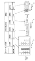
- FIG. 2 is a diagram for explaining the relationship between the display parts displayed on the web browser 5 and the signal data.
- a plurality of display parts are arranged in the drawing displayed as a web page (HMI screen) on the web browser 5.
- the display parts are, for example, a bar graph 24, a numerical display part 25, and a color label part 26.
- Signal data is associated with the display part.
- the data type of signal data includes integer type, floating point type, logical type, etc.
- the bar graph 24 is a part to which integer type signal data is associated. In the bar graph 24, the length of the bar changes according to the signal value.
- the numerical display part 25 is a product to which signal data of a floating-point number type is associated. In the numerical display part 25, the numerical value in the text box changes according to the signal value.
- the color label part 26 is a product to which logical type signal data is associated. The color of the color label part 26 changes according to the signal value.
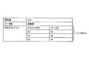
- FIG. 3 is a diagram for explaining an example of a data structure of signal data.
- Signal data is assigned to the display parts of each drawing.
- a graphic ID is assigned to each drawing constituting the HMI screen. Multiple display parts are arranged in the drawing.
- a part ID is assigned to each display part.
- the signal data is data in which a unique identifier that combines a graphic ID and a part ID and a signal value of PLC data are associated with each other.
- one signal value can be associated with a plurality of display parts.
- the signal data has a list of unique identifiers in which the graphic ID and the part ID are combined. This list is called a parts ID list.
- This data structure is created by the signal data generation unit 33 of the web HMI server 3.
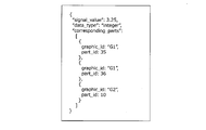
- FIG. 4 is an example in which the data structure shown in FIG. 3 is expressed in JSON.
- the HMI client 4 performs the processing described below by the communication thread and the DOM update thread so as not to cause a delay in the display of the signal data of the web browser 5 even when a large amount of signal data is received.
- the web browser 5 operates the communication thread 7 and the DOM update thread 6 in parallel, and asynchronously executes the data acquisition process and the drawing process.
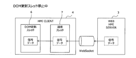
- FIG. 5 is a diagram for explaining processing when the HMI client 4 receives signal data while the DOM update thread is stopped.
- the communication thread 7 transmits a DOM update request event including the received signal data to the DOM update thread 6 when the process in the DOM update thread 6 is stopped (transmission process).
- FIG. 6 is a diagram for explaining processing when the HMI client 4 receives signal data during the operation of the DOM update thread.
- the communication thread 7 stores the received signal data in the buffer area (signal buffer) secured on the memory 200b of the HMI client 4 (buffer processing) when the processing in the DOM update thread 6 is being executed.
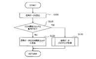
- FIG. 7 is a flowchart expressing the signal data reception process described with reference to FIGS. 5 and 6.
- step S100 the communication processing unit 41 receives signal data from the web HMI server 3.
- step S110 the communication processing unit 41 determines whether the DOM update thread 6 is in operation.
- the communication processing unit 41 executes the process of step S120.
- the communication processing unit 41 executes the process of step S130.
- step S120 the communication processing unit 41 transmits the received signal data to the DOM update thread 6 (transmission processing).
- step S130 the communication processing unit 41 executes a signal data buffering process (FIG. 8) which is a subroutine (buffer process).
- step S120 or S130 the communication processing unit 41 ends the signal data reception processing.
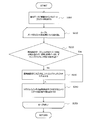
- FIG. 8 is a flowchart for explaining the signal data buffering process executed by the communication processing unit 41 in step S130 of FIG. 7.
- step S200 the communication processing unit 41 acquires the part ID list associated with the signal data.
- the communication processing unit 41 executes the processing of the loop A.
- the communication processing unit 41 executes the processes of steps S220 to S240 for each element of the part ID list.
- step S220 the communication processing unit 41 determines whether signal data having the same unique identifier (combination of graphic ID and part ID) as the received signal data already exists in the signal buffer.
- step S220 If the determination condition is not satisfied in step S220, the process proceeds to step S230.
- step S220 determines whether the determination condition is satisfied in step S220 or not. If the determination condition is satisfied in step S220, the process proceeds to step S240.
- step S230 the communication processing unit 41 creates an entry corresponding to the unique identifier (combination of the graphic ID and the part ID) in the signal buffer. After that, the process proceeds to step S240.
- step S240 the communication processing unit 41 sets the data type and the signal value in the entry corresponding to the unique identifier in the signal buffer.
- the communication processing unit 41 ends the signal data buffering process after executing the processes of steps S220 to S240 for all the elements of the part ID list. According to the loop A, the signal data received from the web HMI server 3 is stored in the signal buffer as signal data decomposed for each unique identifier.
- the unique identifier included in the received signal data and the unique identifier included in the signal data stored in the signal buffer are the same.
- the signal data stored in the signal buffer is overwritten with the received signal data (buffer overwrite processing).
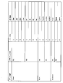
- FIG. 9 is a diagram showing an example of storing data in the signal buffer.
- the signal data temporarily stored in the signal buffer by the signal data buffering process described above is transmitted to the DOM update thread 6 in response to a request from the DOM update thread 6.
- FIG. 10 is a diagram for explaining a process in which the DOM update thread 6 acquires signal data temporarily stored in the signal buffer.
- the DOM update thread 6 After completing the DOM update process for the current signal data, the DOM update thread 6 calls the communication thread 7 and requests that the signal data temporarily stored in the signal buffer be sent. Specifically, the signal data request event is transmitted to the communication thread 7.
- the communication thread 7 When the communication thread 7 receives the signal data request event from the DOM update thread 6, the communication thread 7 transmits the DOM update request event including all the signal data stored in the signal buffer to the DOM update thread 6 (buffer transmission process). ). After transmission, the communication thread 7 deletes the data temporarily stored in the signal buffer.
- the DOM update thread 6 When the DOM update thread 6 receives the DOM update request event, the DOM update thread 6 updates the DOM for all the signal data included in the DOM update request event (DOM update process).
- FIG. 11 is a flowchart for explaining the processing of the DOM update thread 6.
- step S300 the signal data DOM update processing unit 43 receives the DOM update request event from the communication thread.
- step S310 the signal data DOM update processing unit 43 updates the DOM for all the signal data included in the DOM update request event.
- step S320 the signal data DOM update processing unit 43 transmits the signal data request event to the communication thread 7.
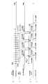
- FIG. 12 is a diagram for explaining the timing at which the DOM update thread 6 requests the signal data and the timing of the rendering process.
- the DOM update thread 6 calls the communication thread 7 (signal data request event) to request the next buffered signal data after completing the DOM update.
- the DOM update thread 6 executes the rendering process at the timing of transmitting the signal data request event.
- the rendering process is a process of reflecting the data expanded in the DOM on the physical screen.
- the rendering processing unit 44 updates the display contents of the display parts displayed on the web browser 5 according to the updated DOM.
- the communication thread 7 overwrites the signal data of the same identifier when buffering the received signal data, so that the data is only the latest signal data. Can be thinned out. Therefore, buffer overflow can be suppressed.
- the DOM update thread 6 transmits a signal data request event to the communication thread 7 after the DOM update process is completed, and the communication thread 7 receives this signal data request event and updates the next signal data to the DOM. Send to thread 6. According to this, the DOM update thread 6 is prohibited from acquiring the next signal data until the DOM update process is completed. Therefore, the rendering process can be executed every time the DOM update process is completed without the DOM update process being continuously executed.
- the display performance of the HMI client 4 can be fully utilized by appropriately executing the rendering process while minimizing the amount of thinning out the signal data. Therefore, according to the present invention, even when a large amount of signal data exceeding the display performance of the HMI client 4 is received, the delay of data display of the web browser 5 can be suppressed.
- the signal data has been mainly described in the above explanation, the alarm data can be processed in the same manner.
- the processing for the signal data in the DOM update thread 6 and the communication thread 7 is also applied to the alarm data.
- the same processing as that of the signal data DOM update processing unit 43 is also applied to the alarm data DOM update processing unit 42.
- the memory 200b may include a main memory and a buffer memory as a buffer area, store a program in the main memory, and store signal data in the buffer memory.
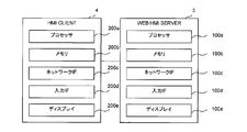
- FIG. 13 is a block diagram showing a hardware configuration example of the web HMI server 3 and the HMI client 4.
- Each process of the web HMI server 3 described above is realized by a process circuit.
- the processing circuit is configured by connecting at least one processor 100a, at least one memory 100b, a network interface 100c, an input interface 100d, and at least one display 100e.
- the processor 100a realizes each function of the web HMI server 3 by executing various programs stored in the memory 100b.
- the memory 100b includes a ROM, a RAM, an HDD, an SSD, and the like.
- the network interface 100c is a device that can connect to the PLC 2 via a computer network and receive PLC data.
- the network interface 100c is a device capable of connecting to the HMI client 4 and transmitting alarm data and signal data.
- the input interface 100d is an input device such as a keyboard, a mouse, and a touch panel.
- Each process of the HMI client 4 described above is realized by a process circuit.
- the processing circuit is configured by connecting at least one processor 200a, at least one memory 200b, a network interface 200c, an input interface 200d, and at least one display 200e.
- the processor 200a realizes each function of the HMI client 4 by executing various programs stored in the memory 200b.
- the memory 200b includes a ROM, a RAM, an HDD, an SSD, and the like.
- the network interface 200c is a device that can connect to the web HMI server 3 via a computer network and receive alarm data and signal data.
- the input interface 200d is an input device such as a keyboard, a mouse, and a touch panel.
- the HMI client 4 may be a mobile terminal such as a tablet.
- the display 200e displays the web browser 5.
- HMI Human-machine interface
- PLC Programmable logic controller
- SCADA web HMI server device
- HMI client terminal HMI client
- Web browser 6
- DOM update thread 7
- Communication thread 21
- Device list 22
- Alarm list 23
- Alarm group list 24
- Numerical display parts 26
- Color label parts 31
- PLC data processing unit 32
- Alarm data generation unit 33
- Signal data generation unit 34
- Communication processing unit 35
- Filtering processing 41
- Alarm data DOM update processing unit 43
- Signal data DOM update processing unit 44 Rendering processing unit 100a Processor 100b Memory 100c Network interface 100d Input interface 100e Display 200a Processor 200b Memory 200c Network interface 200d Input interface 200e Display
Landscapes
- Engineering & Computer Science (AREA)
- Theoretical Computer Science (AREA)
- General Physics & Mathematics (AREA)
- Physics & Mathematics (AREA)
- General Engineering & Computer Science (AREA)
- Software Systems (AREA)
- Automation & Control Theory (AREA)
- Databases & Information Systems (AREA)
- Data Mining & Analysis (AREA)
- Digital Computer Display Output (AREA)
- Programmable Controllers (AREA)
- Information Transfer Between Computers (AREA)
- Information Retrieval, Db Structures And Fs Structures Therefor (AREA)
Abstract
Description
(1)HMI(Human Machine Interface)
HMIは、対象プロセス(監視対象装置)のデータをオペレータに提示し、オペレータがプロセスを監視し制御できるようにする機構である。例えば特許文献1には、SCADAクライアントで動作するHMI画面を備えるSCADA HMIが開示されている。
(2)監視制御システム
監視制御システムは、Programmable Logic Controller(PLC)などによって構成される。監視制御システムは、プロセス上のPLCデータを収集し、プロセスに対して制御コマンドを送る。
(3)遠方入出力装置(Remote Input Output:RIO)
遠方入出力装置は、プロセス内に設置されたセンサと接続し、センサの信号をデジタルのデータに変換し、そのデジタルデータを監視制御システムに送る。
(4)通信基盤
通信基盤は、監視制御システムと遠方入出力装置を接続する。
(1)ウェブブラウザは、パーソナルコンピュータ(PC)、タブレットPCなどの多くの端末機器に搭載されているため、様々な端末機器をSCADA HMIサブシステムに利用可能である。
(2)ウェブブラウザは、高機能なレンダリング機能を有しており、アニメーションをはじめとする高度なGUIインタラクション機能を作り込み易い。
<全体構成>
図1は、本発明の実施の形態1に係るSCADAのシステム構成を説明するためのブロック図である。
ウェブHMIサーバ3は、後述する図13に示すように、プロセッサ100aとメモリ100bとを備える。メモリ100bは、プロセッサ100aにより実行されることで、プロセッサ100aをウェブシステムとして機能させるためのプログラムを記憶する。ウェブシステムは、PLCデータ処理部31、アラームデータ生成部32、信号データ生成部33、通信処理部34を含む。
HMIクライアント4は、後述する図13に示すように、プロセッサ200aとメモリ200bとを備える。メモリ200bは、プロセッサ200aにより実行されることで、プロセッサ100aをウェブブラウザ5として機能させるためのプログラム、および、ウェブブラウザ5上で動作するウェブアプリケーションとして機能させるためのプログラムを記憶する。
次に、図5~図12を参照して、本実施形態に係るHMIクライアント4の特徴的構成について説明する。
図13は、ウェブHMIサーバ3およびHMIクライアント4が有するハードウェア構成例を示すブロック図である。
2 プログラマブルロジックコントローラ(PLC)
3 SCADAウェブHMIサーバ装置(ウェブHMIサーバ)
4 HMIクライアント端末(HMIクライアント)
5 ウェブブラウザ
6 DOM更新スレッド
7 通信スレッド
21 デバイスリスト
22 アラームリスト
23 アラームグループリスト
24 バーグラフ
25 数値表示パーツ
26 色ラベルパーツ
31 PLCデータ処理部
32 アラームデータ生成部
33 信号データ生成部
34 通信処理部
35 フィルタリング処理
41 通信処理部
42 アラームデータDOM更新処理部
43 信号データDOM更新処理部
44 レンダリング処理部
100a プロセッサ
100b メモリ
100c ネットワークインタフェース
100d 入力インタフェース
100e ディスプレイ
200a プロセッサ
200b メモリ
200c ネットワークインタフェース
200d 入力インタフェース
200e ディスプレイ
Claims (4)
- 監視対象に関する表示パーツを特定する固有識別子と、前記監視対象に接続するプログラマブルロジックコントローラから受信した信号値と、を関連付けた信号データを送信するウェブHMIサーバと、
前記表示パーツが配置されたHMI画面をウェブブラウザに表示し、前記ウェブHMIサーバから前記信号データを受信し、当該受信した信号データに対応する前記表示パーツの表示内容を変更するHMIクライアントと、
を備えるSCADAウェブHMIシステムであって、
前記HMIクライアントは、
プログラムを記憶し、かつ、前記信号データをバッファ領域に一時記憶するメモリと、
前記プログラムを実行することにより、前記ウェブブラウザにおいて通信スレッドとDOM更新スレッドとを並列に動作させるように構成されたプロセッサと、
前記ウェブブラウザを表示するディスプレイと、
を備え、
前記通信スレッドは、
前記ウェブHMIサーバから前記信号データを周期的に受信する受信処理と、
前記受信した信号データに含まれた固有識別子と、前記バッファ領域に記憶されている信号データに含まれた固有識別子とが同じである場合に、前記バッファ領域に記憶されている当該信号データを前記受信した信号データで上書きするバッファ上書き処理と、
前記DOM更新スレッドから信号データ要求イベントを受信した場合に、前記バッファ領域に記憶されているすべての信号データを含むDOM更新要求イベントを、前記DOM更新スレッドへ送信するバッファ送信処理と、を実行し、
前記DOM更新スレッドは、
前記DOM更新要求イベントを受信した場合に、前記DOM更新要求イベントに含まれている前記すべての信号データについてDOMを更新するDOM更新処理と、
前記DOMを更新した後に、前記信号データ要求イベントを前記通信スレッドへ送信すると共に、前記更新されたDOMに応じて前記ウェブブラウザに表示された前記表示パーツの表示内容を更新するレンダリング処理と、を実行すること、
を特徴とするSCADAウェブHMIシステム。 - 前記通信スレッドは、
前記DOM更新スレッドにおける処理が停止中である場合に、前記受信した信号データを含む前記DOM更新要求イベントを、前記DOM更新スレッドへ送信する送信処理と、
前記DOM更新スレッドにおける処理が実行中である場合に、前記受信した信号データを前記バッファ領域に記憶させるバッファ処理と、を実行し
前記バッファ上書き処理は、前記バッファ処理において実行されること、
を特徴とする請求項1記載のSCADAウェブHMIシステム。 - 監視対象に関する表示パーツが配置されたHMI画面をウェブブラウザに表示し、前記表示パーツを特定する固有識別子と前記監視対象に関する信号値とを関連付けた信号データを受信し、当該受信した信号データに対応する前記表示パーツの表示内容を変更するHMIクライアントであって、
プログラムを記憶し、かつ、前記信号データをバッファ領域に一時記憶するメモリと、
前記プログラムを実行することにより、前記ウェブブラウザにおいて通信スレッドとDOM更新スレッドとを並列に動作させるように構成されたプロセッサと、
前記ウェブブラウザを表示するディスプレイと、
を備え、
前記通信スレッドは、
前記ウェブHMIサーバから前記信号データを周期的に受信する受信処理と、
前記受信した信号データに含まれた固有識別子と、前記バッファ領域に記憶されている信号データに含まれた固有識別子とが同じである場合に、前記バッファ領域に記憶されている当該信号データを前記受信した信号データで上書きするバッファ上書き処理と、
前記DOM更新スレッドから信号データ要求イベントを受信した場合に、前記バッファ領域に記憶されているすべての信号データを含むDOM更新要求イベントを、前記DOM更新スレッドへ送信するバッファ送信処理と、を実行し、
前記DOM更新スレッドは、
前記DOM更新要求イベントを受信した場合に、前記DOM更新要求イベントに含まれている前記すべての信号データについてDOMを更新するDOM更新処理と、
前記DOMを更新した後に、前記信号データ要求イベントを前記通信スレッドへ送信すると共に、前記更新されたDOMに応じて前記ウェブブラウザに表示された前記表示パーツの表示内容を更新するレンダリング処理と、を実行すること、
を特徴とするHMIクライアント。 - 前記通信スレッドは、
前記DOM更新スレッドにおける処理が停止中である場合に、前記受信した信号データを含む前記DOM更新要求イベントを、前記DOM更新スレッドへ送信する送信処理と、
前記DOM更新スレッドにおける処理が実行中である場合に、前記受信した信号データを前記バッファ領域に記憶させるバッファ処理と、を実行し、
前記バッファ上書き処理は、前記バッファ処理において実行されること、
を特徴とする請求項3記載のHMIクライアント。
Priority Applications (6)
| Application Number | Priority Date | Filing Date | Title |
|---|---|---|---|
| PCT/JP2020/021622 WO2021245752A1 (ja) | 2020-06-01 | 2020-06-01 | Scadaウェブhmiシステムおよびhmiクライアント |
| US17/754,766 US12147207B2 (en) | 2020-06-01 | 2020-06-01 | Scada web HMI system and HMI client |
| CN202080041061.6A CN114080593B (zh) | 2020-06-01 | 2020-06-01 | Scada网页hmi系统及hmi客户端 |
| PH1/2022/552658A PH12022552658A1 (en) | 2020-06-01 | 2020-06-01 | Scada web hmi system and hmi client |
| JP2021568823A JP7148000B2 (ja) | 2020-06-01 | 2020-06-01 | Scadaウェブhmiシステムおよびhmiクライアント |
| TW110106128A TWI764582B (zh) | 2020-06-01 | 2021-02-22 | SCADA Web HMI系統及HMI用戶端 |
Applications Claiming Priority (1)
| Application Number | Priority Date | Filing Date | Title |
|---|---|---|---|
| PCT/JP2020/021622 WO2021245752A1 (ja) | 2020-06-01 | 2020-06-01 | Scadaウェブhmiシステムおよびhmiクライアント |
Related Child Applications (1)
| Application Number | Title | Priority Date | Filing Date |
|---|---|---|---|
| US19/361,080 Continuation US20260042986A1 (en) | 2023-06-27 | 2025-10-17 | Liquid-filled culture bag, method for producing liquid-filled culture bag, and method for using liquid-filled culture bag |
Publications (1)
| Publication Number | Publication Date |
|---|---|
| WO2021245752A1 true WO2021245752A1 (ja) | 2021-12-09 |
Family
ID=78830925
Family Applications (1)
| Application Number | Title | Priority Date | Filing Date |
|---|---|---|---|
| PCT/JP2020/021622 Ceased WO2021245752A1 (ja) | 2020-06-01 | 2020-06-01 | Scadaウェブhmiシステムおよびhmiクライアント |
Country Status (6)
| Country | Link |
|---|---|
| US (1) | US12147207B2 (ja) |
| JP (1) | JP7148000B2 (ja) |
| CN (1) | CN114080593B (ja) |
| PH (1) | PH12022552658A1 (ja) |
| TW (1) | TWI764582B (ja) |
| WO (1) | WO2021245752A1 (ja) |
Cited By (3)
| Publication number | Priority date | Publication date | Assignee | Title |
|---|---|---|---|---|
| JPWO2023188162A1 (ja) * | 2022-03-30 | 2023-10-05 | ||
| WO2023248339A1 (ja) * | 2022-06-21 | 2023-12-28 | 東芝三菱電機産業システム株式会社 | Scadaウェブhmiシステム |
| WO2025013259A1 (ja) * | 2023-07-12 | 2025-01-16 | 株式会社Tmeic | Scadaウェブhmiシステム |
Families Citing this family (2)
| Publication number | Priority date | Publication date | Assignee | Title |
|---|---|---|---|---|
| CN117852504A (zh) | 2022-09-30 | 2024-04-09 | 台达电子工业股份有限公司 | 用于scada系统的报表编辑方法 |
| TWI806783B (zh) * | 2022-09-30 | 2023-06-21 | 台達電子工業股份有限公司 | 用於scada系統的報表編輯方法 |
Citations (2)
| Publication number | Priority date | Publication date | Assignee | Title |
|---|---|---|---|---|
| JP2006338418A (ja) * | 2005-06-03 | 2006-12-14 | Hitachi Zosen Corp | データの配信システム |
| JP6552775B1 (ja) * | 2018-10-31 | 2019-07-31 | 東芝三菱電機産業システム株式会社 | ハイブリッドレンダリングhmi端末装置 |
Family Cites Families (19)
| Publication number | Priority date | Publication date | Assignee | Title |
|---|---|---|---|---|
| US20080195576A1 (en) * | 2004-02-20 | 2008-08-14 | Abb Technology Ltd. | Method, and Computer Based-System and Virtual Asset Register |
| US8295166B2 (en) * | 2007-04-17 | 2012-10-23 | Rockwell Automation Technologies, Inc. | High speed industrial control and data acquistion system and method |
| US7899777B2 (en) * | 2007-09-27 | 2011-03-01 | Rockwell Automation Technologies, Inc. | Web-based visualization mash-ups for industrial automation |
| DE102011053757A1 (de) * | 2011-09-19 | 2013-03-21 | Schneider Electric Automation Gmbh | Verfahren zur Generierung und Handhabung von Applikationen für Komponenten eines Steuerungssytems |
| US20140053056A1 (en) * | 2012-08-16 | 2014-02-20 | Qualcomm Incorporated | Pre-processing of scripts in web browsers |
| CN102917074B (zh) * | 2012-11-09 | 2016-08-03 | 北京奇虎科技有限公司 | 一种实现服务器端浏览器的方法和服务器 |
| US9596313B2 (en) * | 2013-04-12 | 2017-03-14 | Tencent Technology (Shenzhen) Company Limited | Method, terminal, cache server and system for updating webpage data |
| CN103310009B (zh) * | 2013-06-28 | 2017-02-15 | 小米科技有限责任公司 | 一种更新网页数据的方法、装置和终端设备 |
| CN104063806B (zh) * | 2014-06-10 | 2017-04-05 | 国家电网公司 | 在移动终端上实时查看电力系统单线图的方法 |
| JP6477319B2 (ja) | 2015-07-17 | 2019-03-06 | 東芝三菱電機産業システム株式会社 | プラント制御システム |
| US10419568B2 (en) * | 2016-04-01 | 2019-09-17 | Microsoft Technology Licensing, Llc | Manipulation of browser DOM on server |
| US11281963B2 (en) * | 2016-09-26 | 2022-03-22 | Intel Corporation | Programmable neuron core with on-chip learning and stochastic time step control |
| US10558744B2 (en) * | 2016-11-20 | 2020-02-11 | Real Innovations International Llc | Bidirectional networked real-time data exchange using a spreadsheet application |
| CN108667861B (zh) * | 2017-03-28 | 2020-08-07 | 比亚迪股份有限公司 | 通过浏览器对设备实时监控的方法、系统以及服务器 |
| US10134207B2 (en) * | 2017-04-20 | 2018-11-20 | Saudi Arabian Oil Company | Securing SCADA network access from a remote terminal unit |
| EP3629172A1 (de) | 2018-09-26 | 2020-04-01 | Siemens Aktiengesellschaft | Verfahren und anordnung zum zugriff einer anwendung eines industriellen bedien- und beobachtungsgerätes auf zumindest einen dienst |
| KR102243708B1 (ko) * | 2019-01-14 | 2021-04-22 | 엘에스일렉트릭(주) | Hmi 시스템의 편집 툴 갱신 방법 |
| JP7036069B2 (ja) * | 2019-03-15 | 2022-03-15 | オムロン株式会社 | 制御システム、中継装置、および中継プログラム |
| CN110765381B (zh) * | 2019-10-10 | 2022-05-24 | 许昌许继软件技术有限公司 | 基于WebAssembly技术的配网主站的Web发布方法及系统 |
-
2020
- 2020-06-01 US US17/754,766 patent/US12147207B2/en active Active
- 2020-06-01 WO PCT/JP2020/021622 patent/WO2021245752A1/ja not_active Ceased
- 2020-06-01 PH PH1/2022/552658A patent/PH12022552658A1/en unknown
- 2020-06-01 CN CN202080041061.6A patent/CN114080593B/zh active Active
- 2020-06-01 JP JP2021568823A patent/JP7148000B2/ja active Active
-
2021
- 2021-02-22 TW TW110106128A patent/TWI764582B/zh active
Patent Citations (2)
| Publication number | Priority date | Publication date | Assignee | Title |
|---|---|---|---|---|
| JP2006338418A (ja) * | 2005-06-03 | 2006-12-14 | Hitachi Zosen Corp | データの配信システム |
| JP6552775B1 (ja) * | 2018-10-31 | 2019-07-31 | 東芝三菱電機産業システム株式会社 | ハイブリッドレンダリングhmi端末装置 |
Cited By (6)
| Publication number | Priority date | Publication date | Assignee | Title |
|---|---|---|---|---|
| JPWO2023188162A1 (ja) * | 2022-03-30 | 2023-10-05 | ||
| WO2023188162A1 (ja) * | 2022-03-30 | 2023-10-05 | 東芝三菱電機産業システム株式会社 | Scadaウェブhmiクライアント装置およびscadaウェブhmiシステム |
| JP7468784B2 (ja) | 2022-03-30 | 2024-04-19 | 株式会社Tmeic | Scadaウェブhmiクライアント装置およびscadaウェブhmiシステム |
| WO2023248339A1 (ja) * | 2022-06-21 | 2023-12-28 | 東芝三菱電機産業システム株式会社 | Scadaウェブhmiシステム |
| JP7444335B1 (ja) * | 2022-06-21 | 2024-03-06 | 東芝三菱電機産業システム株式会社 | Scadaウェブhmiシステム |
| WO2025013259A1 (ja) * | 2023-07-12 | 2025-01-16 | 株式会社Tmeic | Scadaウェブhmiシステム |
Also Published As
| Publication number | Publication date |
|---|---|
| CN114080593B (zh) | 2025-09-19 |
| US12147207B2 (en) | 2024-11-19 |
| JPWO2021245752A1 (ja) | 2021-12-09 |
| CN114080593A (zh) | 2022-02-22 |
| US20240295862A1 (en) | 2024-09-05 |
| TW202203617A (zh) | 2022-01-16 |
| JP7148000B2 (ja) | 2022-10-05 |
| TWI764582B (zh) | 2022-05-11 |
| PH12022552658A1 (en) | 2024-01-29 |
Similar Documents
| Publication | Publication Date | Title |
|---|---|---|
| JP7148000B2 (ja) | Scadaウェブhmiシステムおよびhmiクライアント | |
| JP7245742B2 (ja) | Scadaウェブhmiサーバ装置 | |
| CN112166389B (zh) | 混合渲染hmi终端装置 | |
| JP6934951B2 (ja) | 装置を横断する普遍的データアクセス | |
| JP7478925B2 (ja) | Scadaウェブhmiクライアント装置およびscadaウェブhmiシステム | |
| US20150127821A1 (en) | Control device | |
| TWI803253B (zh) | Scada網路人機介面系統 | |
| TWI834470B (zh) | SCADA Web HMI系統 | |
| TWI821981B (zh) | SCADA Web HMI系統 | |
| CN109309874B (zh) | 一种焦点更新方法及装置 | |
| US12619207B2 (en) | SCADA web HMI system | |
| US20250258472A1 (en) | Scada web hmi system | |
| WO2023188162A1 (ja) | Scadaウェブhmiクライアント装置およびscadaウェブhmiシステム | |
| WO2025013259A1 (ja) | Scadaウェブhmiシステム | |
| CN121303303A (zh) | 一种基于自然语言理解的规则生成与部署方法及系统 | |
| JP2018063594A (ja) | クライアント装置、管理装置、及び、制御システム |
Legal Events
| Date | Code | Title | Description |
|---|---|---|---|
| ENP | Entry into the national phase |
Ref document number: 2021568823 Country of ref document: JP Kind code of ref document: A |
|
| 121 | Ep: the epo has been informed by wipo that ep was designated in this application |
Ref document number: 20938685 Country of ref document: EP Kind code of ref document: A1 |
|
| WWE | Wipo information: entry into national phase |
Ref document number: 17754766 Country of ref document: US |
|
| NENP | Non-entry into the national phase |
Ref country code: DE |
|
| 122 | Ep: pct application non-entry in european phase |
Ref document number: 20938685 Country of ref document: EP Kind code of ref document: A1 |
|
| WWG | Wipo information: grant in national office |
Ref document number: 202080041061.6 Country of ref document: CN |
|
| WWG | Wipo information: grant in national office |
Ref document number: 202117055898 Country of ref document: IN |