WO2021241415A1 - Anomaly detection system and anomaly detection method - Google Patents
Anomaly detection system and anomaly detection method Download PDFInfo
- Publication number
- WO2021241415A1 WO2021241415A1 PCT/JP2021/019265 JP2021019265W WO2021241415A1 WO 2021241415 A1 WO2021241415 A1 WO 2021241415A1 JP 2021019265 W JP2021019265 W JP 2021019265W WO 2021241415 A1 WO2021241415 A1 WO 2021241415A1
- Authority
- WO
- WIPO (PCT)
- Prior art keywords
- vehicle
- abnormality
- communication
- detection result
- unit
- Prior art date
Links
- 238000001514 detection method Methods 0.000 title claims abstract description 280
- 238000004891 communication Methods 0.000 claims abstract description 414
- 230000005540 biological transmission Effects 0.000 claims abstract description 38
- 230000005856 abnormality Effects 0.000 claims description 296
- 238000012545 processing Methods 0.000 claims description 59
- 238000000034 method Methods 0.000 claims description 23
- 230000008569 process Effects 0.000 claims description 22
- 238000010586 diagram Methods 0.000 description 67
- 238000006243 chemical reaction Methods 0.000 description 27
- 230000004048 modification Effects 0.000 description 23
- 238000012986 modification Methods 0.000 description 23
- 238000001994 activation Methods 0.000 description 17
- 230000004913 activation Effects 0.000 description 15
- 238000004590 computer program Methods 0.000 description 11
- 230000006870 function Effects 0.000 description 11
- 230000002159 abnormal effect Effects 0.000 description 7
- 230000008859 change Effects 0.000 description 7
- 230000004044 response Effects 0.000 description 7
- 230000002093 peripheral effect Effects 0.000 description 6
- 230000000694 effects Effects 0.000 description 5
- 238000005516 engineering process Methods 0.000 description 4
- 230000002547 anomalous effect Effects 0.000 description 2
- 239000000470 constituent Substances 0.000 description 2
- 230000010354 integration Effects 0.000 description 2
- 239000004065 semiconductor Substances 0.000 description 2
- 238000011895 specific detection Methods 0.000 description 2
- 230000003139 buffering effect Effects 0.000 description 1
- 238000002347 injection Methods 0.000 description 1
- 239000007924 injection Substances 0.000 description 1
- 238000004519 manufacturing process Methods 0.000 description 1
- 239000000463 material Substances 0.000 description 1
Images


Classifications
-
- G—PHYSICS
- G06—COMPUTING; CALCULATING OR COUNTING
- G06F—ELECTRIC DIGITAL DATA PROCESSING
- G06F16/00—Information retrieval; Database structures therefor; File system structures therefor
- G06F16/20—Information retrieval; Database structures therefor; File system structures therefor of structured data, e.g. relational data
- G06F16/24—Querying
- G06F16/245—Query processing
- G06F16/2455—Query execution
-
- H—ELECTRICITY
- H04—ELECTRIC COMMUNICATION TECHNIQUE
- H04Q—SELECTING
- H04Q9/00—Arrangements in telecontrol or telemetry systems for selectively calling a substation from a main station, in which substation desired apparatus is selected for applying a control signal thereto or for obtaining measured values therefrom
-
- B—PERFORMING OPERATIONS; TRANSPORTING
- B60—VEHICLES IN GENERAL
- B60R—VEHICLES, VEHICLE FITTINGS, OR VEHICLE PARTS, NOT OTHERWISE PROVIDED FOR
- B60R16/00—Electric or fluid circuits specially adapted for vehicles and not otherwise provided for; Arrangement of elements of electric or fluid circuits specially adapted for vehicles and not otherwise provided for
- B60R16/02—Electric or fluid circuits specially adapted for vehicles and not otherwise provided for; Arrangement of elements of electric or fluid circuits specially adapted for vehicles and not otherwise provided for electric constitutive elements
- B60R16/023—Electric or fluid circuits specially adapted for vehicles and not otherwise provided for; Arrangement of elements of electric or fluid circuits specially adapted for vehicles and not otherwise provided for electric constitutive elements for transmission of signals between vehicle parts or subsystems
- B60R16/0231—Circuits relating to the driving or the functioning of the vehicle
-
- G—PHYSICS
- G06—COMPUTING; CALCULATING OR COUNTING
- G06F—ELECTRIC DIGITAL DATA PROCESSING
- G06F11/00—Error detection; Error correction; Monitoring
- G06F11/07—Responding to the occurrence of a fault, e.g. fault tolerance
-
- G—PHYSICS
- G06—COMPUTING; CALCULATING OR COUNTING
- G06F—ELECTRIC DIGITAL DATA PROCESSING
- G06F21/00—Security arrangements for protecting computers, components thereof, programs or data against unauthorised activity
- G06F21/50—Monitoring users, programs or devices to maintain the integrity of platforms, e.g. of processors, firmware or operating systems
- G06F21/55—Detecting local intrusion or implementing counter-measures
-
- H—ELECTRICITY
- H04—ELECTRIC COMMUNICATION TECHNIQUE
- H04L—TRANSMISSION OF DIGITAL INFORMATION, e.g. TELEGRAPHIC COMMUNICATION
- H04L12/00—Data switching networks
- H04L12/28—Data switching networks characterised by path configuration, e.g. LAN [Local Area Networks] or WAN [Wide Area Networks]
- H04L12/40—Bus networks
-
- H—ELECTRICITY
- H04—ELECTRIC COMMUNICATION TECHNIQUE
- H04L—TRANSMISSION OF DIGITAL INFORMATION, e.g. TELEGRAPHIC COMMUNICATION
- H04L12/00—Data switching networks
- H04L12/28—Data switching networks characterised by path configuration, e.g. LAN [Local Area Networks] or WAN [Wide Area Networks]
- H04L12/46—Interconnection of networks
-
- H—ELECTRICITY
- H04—ELECTRIC COMMUNICATION TECHNIQUE
- H04L—TRANSMISSION OF DIGITAL INFORMATION, e.g. TELEGRAPHIC COMMUNICATION
- H04L63/00—Network architectures or network communication protocols for network security
- H04L63/14—Network architectures or network communication protocols for network security for detecting or protecting against malicious traffic
- H04L63/1408—Network architectures or network communication protocols for network security for detecting or protecting against malicious traffic by monitoring network traffic
- H04L63/1425—Traffic logging, e.g. anomaly detection
-
- H—ELECTRICITY
- H04—ELECTRIC COMMUNICATION TECHNIQUE
- H04L—TRANSMISSION OF DIGITAL INFORMATION, e.g. TELEGRAPHIC COMMUNICATION
- H04L63/00—Network architectures or network communication protocols for network security
- H04L63/14—Network architectures or network communication protocols for network security for detecting or protecting against malicious traffic
- H04L63/1441—Countermeasures against malicious traffic
- H04L63/1466—Active attacks involving interception, injection, modification, spoofing of data unit addresses, e.g. hijacking, packet injection or TCP sequence number attacks
-
- H—ELECTRICITY
- H04—ELECTRIC COMMUNICATION TECHNIQUE
- H04L—TRANSMISSION OF DIGITAL INFORMATION, e.g. TELEGRAPHIC COMMUNICATION
- H04L67/00—Network arrangements or protocols for supporting network services or applications
- H04L67/01—Protocols
- H04L67/12—Protocols specially adapted for proprietary or special-purpose networking environments, e.g. medical networks, sensor networks, networks in vehicles or remote metering networks
-
- H—ELECTRICITY
- H04—ELECTRIC COMMUNICATION TECHNIQUE
- H04W—WIRELESS COMMUNICATION NETWORKS
- H04W4/00—Services specially adapted for wireless communication networks; Facilities therefor
- H04W4/30—Services specially adapted for particular environments, situations or purposes
- H04W4/40—Services specially adapted for particular environments, situations or purposes for vehicles, e.g. vehicle-to-pedestrians [V2P]
- H04W4/48—Services specially adapted for particular environments, situations or purposes for vehicles, e.g. vehicle-to-pedestrians [V2P] for in-vehicle communication
-
- H—ELECTRICITY
- H04—ELECTRIC COMMUNICATION TECHNIQUE
- H04L—TRANSMISSION OF DIGITAL INFORMATION, e.g. TELEGRAPHIC COMMUNICATION
- H04L12/00—Data switching networks
- H04L12/28—Data switching networks characterised by path configuration, e.g. LAN [Local Area Networks] or WAN [Wide Area Networks]
- H04L12/40—Bus networks
- H04L2012/40208—Bus networks characterized by the use of a particular bus standard
- H04L2012/40215—Controller Area Network CAN
-
- H—ELECTRICITY
- H04—ELECTRIC COMMUNICATION TECHNIQUE
- H04L—TRANSMISSION OF DIGITAL INFORMATION, e.g. TELEGRAPHIC COMMUNICATION
- H04L12/00—Data switching networks
- H04L12/28—Data switching networks characterised by path configuration, e.g. LAN [Local Area Networks] or WAN [Wide Area Networks]
- H04L12/40—Bus networks
- H04L2012/40267—Bus for use in transportation systems
- H04L2012/40273—Bus for use in transportation systems the transportation system being a vehicle
-
- H—ELECTRICITY
- H04—ELECTRIC COMMUNICATION TECHNIQUE
- H04L—TRANSMISSION OF DIGITAL INFORMATION, e.g. TELEGRAPHIC COMMUNICATION
- H04L45/00—Routing or path finding of packets in data switching networks
-
- H—ELECTRICITY
- H04—ELECTRIC COMMUNICATION TECHNIQUE
- H04L—TRANSMISSION OF DIGITAL INFORMATION, e.g. TELEGRAPHIC COMMUNICATION
- H04L45/00—Routing or path finding of packets in data switching networks
- H04L45/74—Address processing for routing
- H04L45/745—Address table lookup; Address filtering
-
- H—ELECTRICITY
- H04—ELECTRIC COMMUNICATION TECHNIQUE
- H04Q—SELECTING
- H04Q2209/00—Arrangements in telecontrol or telemetry systems
- H04Q2209/80—Arrangements in the sub-station, i.e. sensing device
- H04Q2209/82—Arrangements in the sub-station, i.e. sensing device where the sensing device takes the initiative of sending data
- H04Q2209/823—Arrangements in the sub-station, i.e. sensing device where the sensing device takes the initiative of sending data where the data is sent when the measured values exceed a threshold, e.g. sending an alarm
Definitions
- This disclosure relates to an abnormality detection system and an abnormality detection method for detecting an abnormality in an in-vehicle network system.
- ECUs electronice control units
- in-vehicle network The network connecting these ECUs.
- CAN Controller Area Network
- the communication path is composed of two buses, and the ECU connected to the buses is called a node.
- Each node connected to the bus sends and receives a message called a frame.
- the transmission node In CAN, there is no identifier that points to the destination node or source node, the transmission node sends with an ID called a message ID for each frame, and each receiving node receives only a predetermined message ID. Therefore, there is a threat that the automobile can be illegally controlled by connecting the ECU to the CAN bus and transmitting a frame containing an abnormal control command by pretending to be a legitimate ECU.
- Patent Document 1 a method of detecting the injection of an illegal message that is difficult to determine in the vehicle by using a server system outside the vehicle has been proposed (for example, Patent Document 1).
- Patent Document 1 when communication to the server system outside the vehicle is intentionally disturbed or when an abnormality occurs in the vehicle that prevents communication outside the vehicle, information on the abnormality inside the vehicle occurs. Can not be notified to the server system, and there is a problem that the server system cannot appropriately detect an abnormality.
- an object of the present disclosure to provide an abnormality detection system or the like that can more reliably notify the outside of the vehicle of information on the abnormality that has occurred inside the vehicle.
- the anomaly detection system is an anomaly detection system in an in-vehicle network system provided with one or more electronic control devices mounted on a vehicle, and in the in-vehicle network system, the vehicle and the vehicle.
- a specific device outside the vehicle can communicate with a specific device via a plurality of communication paths, and the abnormality detection system has an abnormality detection unit that detects an abnormality in the vehicle and the vehicle based on the occurrence of the specific abnormality.
- FIG. 1 is a diagram showing an example of the overall configuration of the in-vehicle network system according to the first embodiment.
- FIG. 2 is a diagram showing an example of the configuration of the ECU according to the first embodiment.
- FIG. 3 is a diagram showing an example of a detection rule in the first embodiment.
- FIG. 4 is a diagram showing an example of the format of the detection result status message in the vehicle according to the first embodiment.
- FIG. 5 is a diagram showing an example of a detection result management table according to the first embodiment.
- FIG. 6 is a diagram showing an example of the configuration of IVI according to the first embodiment.
- FIG. 7 is a diagram showing an example of the configuration of the communication ECU according to the first embodiment.
- FIG. 1 is a diagram showing an example of the overall configuration of the in-vehicle network system according to the first embodiment.
- FIG. 2 is a diagram showing an example of the configuration of the ECU according to the first embodiment.
- FIG. 3 is a diagram showing an example of a
- FIG. 8 is a diagram showing an example of the format of the detection result status message to the outside of the vehicle according to the first embodiment.
- FIG. 9 is a diagram showing an example of the configuration of the server according to the first embodiment.
- FIG. 10 is a diagram showing an example of a sequence related to abnormal information communication processing according to the first embodiment.
- FIG. 11 is a diagram showing an example of a sequence related to the abnormality information transmission route switching process in the first embodiment.
- FIG. 12 is a diagram showing an example of the configuration of the server in the first modification of the first embodiment.
- FIG. 13 is a diagram showing an example of a sequence related to the abnormality information transmission path switching process in the first modification of the first embodiment.
- FIG. 14 is a diagram showing an example of the configuration of the communication ECU in the second modification of the first embodiment.
- FIG. 15 is a diagram showing an example of a sequence related to the abnormality information transmission path switching process in the second modification of the first embodiment.
- FIG. 16 is a diagram showing an example of the overall configuration of the vehicle-mounted network system according to the second embodiment.
- FIG. 17 is a diagram showing an example of the configuration of the communication ECU according to the second embodiment.
- FIG. 18 is a diagram showing an example of the configuration of the charging ECU according to the second embodiment.
- FIG. 19 is a diagram showing an example of a detection rule according to the second embodiment.
- FIG. 20 is a diagram showing an example of the format of the detection result status message in the vehicle according to the second embodiment.
- FIG. 21 is a diagram showing an example of the format of the detection result status message to the outside of the vehicle according to the second embodiment.
- FIG. 22 is a diagram showing an example of a sequence related to the abnormality information transmission route switching process in the second embodiment.
- FIG. 23 is a diagram showing an example of a sequence related to abnormal information communication processing according to the second embodiment.
- FIG. 24 is a diagram showing an example of the configuration of the charging ECU in the first modification of the second embodiment.
- FIG. 25 is a diagram showing an example of a sequence related to anomalous information communication processing in the first modification of the second embodiment.
- FIG. 26 is a diagram showing an example of display of a communication path switched to an abnormality that has occurred in another embodiment.
- FIG. 27 is a diagram showing an example of a detailed display of the communication path switched to the generated abnormality in another embodiment.
- FIG. 28 is a diagram showing another example of the detailed display of the communication path switched to the occurrence of the abnormality in the other embodiment.
- FIG. 29 is a diagram showing an example of a display for setting a correspondence relationship between an abnormality that has occurred and a communication path that can be switched in another embodiment.
- FIG. 30 is a diagram showing an example of a software configuration of a virtual environment realized by a computer in another embodiment.
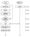
- FIG. 31 is a flowchart showing an example of an abnormality detection method according to another embodiment.
- the anomaly detection system is an anomaly detection system in an in-vehicle network system provided with one or more electronic control devices mounted on a vehicle, and in the in-vehicle network system, the vehicle and the vehicle.
- a specific device outside the vehicle can communicate with a specific device via a plurality of communication paths, and the abnormality detection system has an abnormality detection unit that detects an abnormality in the vehicle and the vehicle based on the occurrence of the specific abnormality.
- the determination unit for determining the communication path for transmitting the abnormality detection result information indicating the abnormality detection result in the above-mentioned specific device from the plurality of communication paths, and the specific communication path using the determined communication path. It has an abnormality detection result transmission unit that transmits the abnormality detection result information to the device.
- the specific abnormality may include an abnormality in communication with the outside of the vehicle.
- the abnormality in communication with the outside of the vehicle may include an abnormality in the transmission processing of the abnormality detection result information to the specific device.
- the communication route can be determined only by the device involved in the transmission process, and the time required for determining the communication route can be reduced.
- the abnormality in communication with the outside of the vehicle may include an abnormality in the reception processing of the abnormality detection result information in the specific device.
- the specific abnormality may include an abnormality in the vehicle.
- the determination unit collates the generated specific abnormality with a table associated with a communication path for each type of abnormality, so that the determination unit transmits the abnormality detection result information to the specific device.
- the route may be determined from the plurality of communication routes.
- communication routes according to the importance of the abnormality are associated with the assumed abnormality in the table, so that communication can be flexibly performed according to the importance of the abnormality. It becomes possible to determine the route.
- the abnormality detection system may further have a change unit for changing the correspondence between the type of abnormality in the table and the communication path.
- the plurality of communication paths may include a communication path via a TCU (Telematics Control Unit).
- TCU Transmission Control Unit
- the plurality of communication paths may include a communication path via IVI (In-Vehicle Infotainment).
- IVI In-Vehicle Infotainment
- the plurality of communication paths may include a communication path via an electronic control device in charge of charging the battery.
- the determination unit sets a communication path for transmitting the abnormality detection result information to the specific device from among the plurality of communication paths according to the occurrence of the specific abnormality and the state of the vehicle. You may decide.
- the abnormality detection system may further have a communication path transmission unit that transmits communication path information indicating a determined communication path.
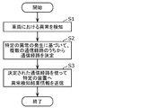
- the abnormality detection method is an abnormality detection method in an in-vehicle network system provided with one or more electronic control devices mounted on a vehicle, and in the in-vehicle network system, the vehicle and the vehicle.
- a specific device outside the vehicle can communicate via a plurality of communication paths, and the abnormality detection method is based on an abnormality detection step for detecting an abnormality in the vehicle and the occurrence of a specific abnormality.
- the determination step for determining the communication path for transmitting the abnormality detection result information indicating the abnormality detection result in the vehicle to the specific device from the plurality of communication paths, and the determined communication path are used. It includes an abnormality detection result transmission step of transmitting the abnormality detection result information to a specific device.
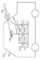
- FIG. 1 is a diagram showing an example of the overall configuration of the in-vehicle network system 1000 according to the first embodiment.
- the in-vehicle network system 1000 is composed of a vehicle 1001 and a server 1400 that operates by connecting to the vehicle 1001 via a network.
- the in-vehicle network system 1000 is provided with one or more ECUs mounted on the vehicle 1001. Further, the in-vehicle network system 1000 includes an abnormality detection system.
- the anomaly detection system is a computer that includes a processor, communication interface, memory, and so on.
- the memory is a ROM (Read Only Memory), a RAM (Random Access Memory), or the like, and can store a program executed by the processor.
- the components of the anomaly detection system are realized by a processor that executes a program stored in a memory, a communication interface, and the like.
- the anomaly detection system may be a device realized by one housing. Further, the components of the abnormality detection system may be distributed and arranged in a plurality of devices (a plurality of housings).
- the vehicle 1001 communicates with the ECUs 1100a, 1100b and 1100c connected by various in-vehicle networks, the brakes 1011, the handles 1012 and the accelerator 1013 which are the controlled objects of the ECUs 1100a to 1100c, and the ECUs 1100a to 1100c via the in-vehicle network. It is composed of IVI1200 and communication ECU1300.
- the ECUs 1100a to 1100c realize control of the vehicle by transmitting and receiving communication messages to and from each other through the in-vehicle network.
- CAN is used for in-vehicle networks.
- the ECUs 1100a to 1100c are collectively referred to as an ECU 1100.
- the IVI1200 is provided with a display unit capable of displaying the state inside the vehicle 1001, and presents various information indicating the state inside the vehicle 1001 to the driver. Further, the IVI 1200 communicates with the server 1400 and transmits / receives a message between the server 1400 and another ECU in the vehicle 1001. The IVI1200 may be capable of communicating with devices outside the vehicle other than the server 1400.
- the communication ECU 1300 communicates with the server 1400 and transmits / receives a message between the server 1400 and another ECU in the vehicle 1001.
- the communication ECU 1300 is an example of TCU.
- Server 1400 remotely monitors to ensure the safety of the vehicle. Further, the server 1400 may detect an illegal message that is difficult to determine in the vehicle 1001 by analyzing the message transmitted from the vehicle 1001.
- the server 1400 is an example of a specific device outside the vehicle 1001.
- the vehicle 1001 and the server 1400 can communicate with each other via a plurality of communication paths.
- the plurality of communication paths include a communication path via the communication ECU 1300 (TCU) and a communication path via the IVI1200.
- FIG. 2 is a diagram showing an example of the configuration of the ECU 1100 according to the first embodiment.
- the ECU 1100 is composed of a communication unit 1101, a message conversion unit 1102, an activation management unit 1103, a cryptographic processing unit 1104, a key management unit 1105, a detection result management unit 1106, and a detection result holding unit 1107. ..
- the communication unit 1101 communicates with various sensors and other ECUs via the in-vehicle network.
- the communication unit 1101 notifies the message conversion unit 1102 of the received message and the sensor value. Further, the communication unit 1101 transmits the message notified by the message conversion unit 1102 or the detection result management unit 1106 to other ECUs and various sensors.
- the message conversion unit 1102 converts the sensor value notified from the communication unit 1101 based on the format of the vehicle-mounted network, and transmits it to another ECU via the communication unit 1101. Further, the message conversion unit 1102 converts the communication message received from the communication unit 1101 into sensor values and setting information, and transmits the communication message to various sensors via the communication unit 1101. Further, the message conversion unit 1102 notifies the encryption processing unit 1104 of the received message.
- the activation management unit 1103 is in charge of the activation process of the ECU 1100 and the activation process of each function of the ECU 1100.
- the activation management unit 1103 notifies the encryption processing unit 1104 when it is necessary to check the validity of the activation contents at the time of activation.
- the encryption processing unit 1104 verifies the MAC (message authentication code) included in the message using the key and certificate held by the key management unit 1105, and notifies the detection result management unit 1106 of the result. Further, the encryption processing unit 1104 performs a validity check at the time of activation of the device or function in response to the notification content from the activation management unit 1103, and notifies the detection result management unit 1106 of the result.
- the encryption processing unit 1104 is an example of an abnormality detection unit that detects an abnormality in the vehicle 1001 (for example, an abnormality due to an attack or an abnormality due to a failure).
- the key management unit 1105 holds the key and certificate used by the encryption processing unit 1104.
- the detection result management unit 1106 stores the abnormality detection result in the vehicle 1001 notified from the encryption processing unit 1104 in the detection result holding unit 1107 together with the peripheral information. Further, the detection result management unit 1106 transmits the holding contents of the detection result holding unit 1107 to the communication ECU 1300 via the communication unit 1101 as a detection result status message (also referred to as abnormality detection result information).
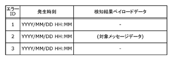
- FIG. 3 shows an example of a detection rule for detecting an abnormality in the vehicle 1001
- FIG. 4 shows an example of a message format of a detection result status message.
- the detection result holding unit 1107 holds the detection result data notified by the detection result management unit 1106. Further, the detection result holding unit 1107 notifies the detection result management unit 1106 of the detection result data in response to a read instruction from the detection result management unit 1106. An example of the specific holding contents of the detection result holding unit 1107 is shown in FIG.
- FIG. 3 is a diagram showing an example of a detection rule for detecting an abnormality in a message of an in-vehicle network according to the first embodiment.
- the detection rule includes a table in which specific detection contents and error IDs corresponding to the respective detection contents are associated with each other. When an abnormality described in the table occurs, the corresponding error ID and peripheral information are saved as a detection result.
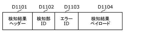
- FIG. 4 is a diagram showing an example of the format of the detection result status message in the vehicle according to the first embodiment.
- the payload of the detection result status message (in other words, the detection result status message transmitted to the in-vehicle network) in the vehicle is composed of the detection result header D1101, the detection unit ID D1102, the error ID D1103, and the detection result payload D1104. Will be done.
- the detection result header D1101 is an area for storing a value indicating the type and number of data that follow. By putting a predetermined number at the beginning, the detection result header D1101 indicates that the subsequent data is a message indicating the detection result status, and at the same time, plays a role of transmitting the contents to the receiver.
- the detection unit ID D1102 stores a number uniquely set for identifying the abnormality detection unit in the ECU 1100a, ECU 1100b, and ECU 1100c.
- the error ID D1103 indicates the type of abnormality included in the detection result from the abnormality detection unit specified by the detection unit ID D1102.
- the detection result payload D1104 indicates information that serves as error peripheral information.
- FIG. 5 is a diagram showing an example of a detection result management table according to the first embodiment.
- the detection result management unit 1106 creates a detection result management table based on the detection result status message in the vehicle, and stores it in the detection result holding unit 1107.
- the detection result management table is composed of an error ID corresponding to the abnormality detected by the encryption processing unit 1104, a time when the abnormality occurs, and detection result payload data as peripheral information.
- FIG. 6 is a diagram showing an example of the configuration of IVI1200 according to the first embodiment.
- the IVI1200 is composed of an in-vehicle communication unit 1201, a conversion unit 1202, an out-of-vehicle communication unit 1203, and a display unit 1204.
- the in-vehicle communication unit 1201 notifies the conversion unit 1202 of a message received from another ECU in the vehicle. Further, the in-vehicle communication unit 1201 transmits the message notified by the conversion unit 1202 to other ECUs in the vehicle. Further, the in-vehicle communication unit 1201 notifies the display unit 1204 of the information that needs to be notified to the driver.
- the conversion unit 1202 converts the data that needs to be transferred from the messages received via one of the in-vehicle communication unit 1201 and the out-of-vehicle communication unit 1203 into a predetermined format, and the in-vehicle communication unit 1201 and the out-of-vehicle communication unit 1203. Send to the other side of.
- the out-of-vehicle communication unit 1203 notifies the conversion unit 1202 of the message received from the server 1400. Further, the out-of-vehicle communication unit 1203 transmits the message notified by the conversion unit 1202 to the server 1400. Further, the out-of-vehicle communication unit 1203 notifies the display unit 1204 of the information that needs to be notified to the driver.
- the out-of-vehicle communication unit 1203 transmits the abnormality detection result information to the server 1400 using the determined communication route. Become a department.
- the display unit 1204 is notified of information from the in-vehicle communication unit 1201 and the out-of-vehicle communication unit 1203, and presents necessary information to the driver based on the notified information.
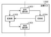
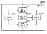
- FIG. 7 is a diagram showing an example of the configuration of the communication ECU 1300 according to the first embodiment.
- the communication ECU 1300 includes an in-vehicle communication unit 1301, a conversion unit 1302, an out-of-vehicle communication unit 1303, and a switching unit 1304.
- the in-vehicle communication unit 1301 notifies the conversion unit 1302 of a message received from another ECU in the vehicle. Further, the in-vehicle communication unit 1301 transmits the message notified by the conversion unit 1302 to other ECUs in the vehicle.
- the conversion unit 1302 converts the data that needs to be transferred among the messages received via one of the in-vehicle communication unit 1301 and the out-of-vehicle communication unit 1303 into a predetermined format, and the in-vehicle communication unit 1301 and the out-of-vehicle communication unit 1303. Send to the other side of. Further, the conversion unit 1302 receives the notification from the switching unit 1304, converts the notified information, and then notifies the in-vehicle communication unit 1301.
- the out-of-vehicle communication unit 1303 notifies the conversion unit 1302 of the message received from the server 1400. Further, the out-of-vehicle communication unit 1303 transmits the message notified by the conversion unit 1302 to the server 1400. Further, the out-of-vehicle communication unit 1303 notifies the switching unit 1304 of information to be transmitted to the server 1400 (specifically, a detection result status message (abnormality detection result information)) when a communication error occurs.
- FIG. 8 shows an example of the message format of the detection result status message transmitted to the server 1400.
- the out-of-vehicle communication unit 1303 transmits the abnormality detection result information to the server 1400 using the determined communication path. It becomes a transmitter.
- the switching unit 1304 receives notification of information to be transmitted to the server 1400 from the out-of-vehicle communication unit 1303, and can communicate with the server 1400 using a communication path different from the communication path currently used for communication with the server 1400. In order to notify the ECU having the external communication unit of the information to be transmitted to the server 1400, the conversion unit 1302 is notified of the information.
- the switching unit 1304 determines a communication route for transmitting the abnormality detection result information indicating the abnormality detection result in the vehicle 1001 to the server 1400 from among a plurality of communication routes based on the occurrence of a specific abnormality. This is an example.
- the switching unit 1304 switches the communication path used for communication between the vehicle 1001 and the server 1400 to the determined communication path.
- FIG. 8 is a diagram showing an example of the format of the detection result status message to the outside of the vehicle according to the first embodiment.
- the payload of the detection result status message outside the vehicle includes the detection result header D1201, the vehicle ID D1202, the detection unit ID D1203, the error ID D1204, and the detection result payload. It is composed of D1205 and.
- the detection result header D1201 is an area for storing a value indicating the type and number of data that follow. By putting a predetermined number at the beginning, the detection result header D1201 indicates that the subsequent data is a message indicating the detection result status, and at the same time, plays a role of transmitting the contents to the receiver.
- the vehicle ID D1202 stores a number uniquely set to identify the vehicle 1001.
- the detection unit ID D1203 stores a number uniquely set for identifying the abnormality detection unit in the ECU 1100a, ECU 1100b, and ECU 1100c.
- the error ID D1204 indicates an error ID indicating the type of abnormality included in the detection result from the abnormality detection unit identified by the detection unit ID D1203.
- the detection result payload D1205 indicates the result of determining the detection result status.
- the detection result status message to the outside of the vehicle is the one in which the vehicle ID D1202 is added to the detection result status message to the inside of the vehicle in order to specify from which vehicle the server 1400 is the message.
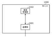
- FIG. 9 is a diagram showing an example of the configuration of the server 1400 according to the first embodiment.
- the server 1400 includes a communication unit 1401 and a vehicle management unit 1402.
- the communication unit 1401 communicates with the vehicle 1001 and notifies the vehicle management unit 1402 of the received message. Further, the communication unit 1401 transmits the content notified from the vehicle management unit 1402 to the vehicle 1001.
- the vehicle management unit 1402 communicates with the vehicle 1001 via the communication unit 1401 and manages the information in the vehicle 1001. For example, the vehicle management unit 1402 may detect an invalid message by analyzing the message transmitted from the vehicle 1001.
- FIG. 10 is a diagram showing an example of a sequence related to abnormal information communication processing according to the first embodiment.
- FIG. 10 shows an example of a sequence in which the ECU 1100 aggregates abnormality information and transmits it to the communication ECU 1300.
- the ECU 1100 waits for the occurrence of an abnormality, and the communication ECU 1300 waits for the occurrence of communication (reception of a notification from the ECU 1100).
- the ECU 1100 increments the counter value indicating the number of times the abnormality has occurred by one.
- the ECU 1100 determines whether or not the counter value of the abnormality exceeds a predetermined number of times (that is, whether or not the specified number of abnormalities have occurred). Proceed to S1101 respectively.
- the specified number of times is set for each type of abnormality, for example.
- the number of times to be set is not particularly limited, but is set according to, for example, the type of abnormality.
- the ECU 1100 transmits information (abnormality detection result information) that aggregates the contents of the generated abnormality to the communication ECU 1300.
- FIG. 11 is a diagram showing an example of a sequence related to the abnormality information transmission route switching process in the first embodiment.
- the communication ECU 1300 transmits the abnormality detection result information to the server 1400 and a transmission error occurs as a specific abnormality
- the communication path is switched to the communication path via the IVI1200 (in other words, a plurality of).
- An example of a sequence of processing for transmitting abnormality detection result information from IVI1200 (determining a communication path via IVI1200) is shown.
- the communication ECU 1300 waits for the generation of communication (receipt of notification from the ECU 1100), the IVI1200 waits for the generation of communication (reception of notification from the communication ECU 1300), and the server 1400 waits for the generation of communication (communication). (Reception of notification from ECU 1300 or IVI1200) is on standby.
- the communication ECU 1300 transmits the received abnormality detection result information to the server 1400.
- the communication ECU 1300 confirms whether or not a transmission error has occurred as a specific abnormality, and if it does not occur, the process ends normally, and if it does occur, the process proceeds to S1204.
- the specific abnormality includes the abnormality of communication with the outside of the vehicle 1001 (for example, the server 1400), and the abnormality of the communication with the outside of the vehicle is the process of transmitting the abnormality detection result information to the server 1400. Including abnormalities.
- the communication ECU 1300 increments the counter value related to the number of transmission retries by one.
- the communication ECU 1300 confirms whether or not the number of transmission retries (counter value above) exceeds the specified number, and if it exceeds, proceeds to S1206, and if not, proceeds to S1202.
- the specified number of times is not particularly limited and is set as appropriate.
- the communication ECU 1300 resets the counter value related to the retry of transmission.
- the communication ECU 1300 notifies another communication ECU (here, IVI1200) of the abnormality detection result information that was about to be transmitted to the server 1400.
- the IVI1200 transmits the abnormality detection result information received from the communication ECU 1300 to the server 1400.
- an ECU that is in charge of communication with the outside of the vehicle in the network system of the vehicle 1001 when notifying an information on an abnormality occurring in the vehicle to a system outside the vehicle (for example, a server 1400). Even if an abnormality occurs in the communication of (for example, communication ECU 1300), by setting a communication path by another out-of-vehicle communication ECU (for example, IVI1200) as an alternative in advance, information on the abnormality is appropriately notified to the system outside the vehicle. It becomes possible to ensure the safety of the entire vehicle.
- FIG. 12 is a diagram showing an example of the configuration of the server 11400 in the first modification of the first embodiment.
- the server 11400 includes a communication unit 11401, a vehicle management unit 1402, and a switching unit 11403. In the same configuration as in the first embodiment, the same number is assigned and the description thereof will be omitted.
- the communication unit 11401 communicates with the vehicle 1001 and notifies the vehicle management unit 1402 of the received message. Further, the communication unit 11401 transmits the content notified from the vehicle management unit 1402 to the vehicle 1001. Further, the communication unit 11401 notifies the switching unit 11403 when a communication error occurs.
- the switching unit 11403 receives a notification from the communication unit 11401 and communicates with an ECU having an out-of-vehicle communication unit capable of communicating with the server 11400 using a communication path other than the communication path currently used for communication with the vehicle. Therefore, the communication unit 11401 is notified.
- the switching unit 11403 is a determination unit that determines a communication path for transmitting the abnormality detection result information indicating the abnormality detection result in the vehicle to the server 11400 based on the occurrence of a specific abnormality from among a plurality of communication paths. This is just one example.
- the switching unit 11403 switches the communication path used for communication between the vehicle and the server 11400 to the determined communication path.
- FIG. 13 is a diagram showing an example of a sequence related to the abnormality information transmission path switching process in the first modification of the first embodiment.
- the server 11400 requests the communication ECU 1300 for the abnormality detection result information and a communication error occurs as a specific abnormality
- the request destination is switched to the IVI1200 (in other words, among a plurality of communication paths).
- IVI1200 Determining the communication path via IVI1200
- an example of the processing sequence for transmitting the abnormality detection result information from IVI1200 is shown.
- the same numbers are assigned and the description thereof will be omitted.
- the server 11400 periodically requests the communication ECU 1300 for the abnormality detection result information.
- the server 11400 confirms whether or not the response to the request can be received normally, and if it can be received, it ends normally, and if it has not been received, it proceeds to S11204.
- the specific abnormality includes the abnormality of communication with the outside of the vehicle 1001 (for example, the server 11400), and the abnormality of the communication with the outside of the vehicle is the abnormality of the reception processing of the abnormality detection result information in the server 11400. including.
- the server 11400 increments the counter value related to the retry of the request by one.
- the server 11400 confirms whether the number of request retries (counter value above) exceeds the specified number, and if it exceeds, proceeds to S11206, and if not, proceeds to S11202.
- the server 11400 resets the counter value related to the retry of the request.
- the server 11400 switches the request destination of the abnormality detection result information from the communication ECU 1300 to the IVI1200, and transmits the request.
- IVI1200 requests and acquires abnormality detection result information from another ECU (for example, ECU 1100) in response to a received request.
- the ECU in charge of communication with the outside of the vehicle in the network system of the vehicle 1001 when notifying the system outside the vehicle of information regarding an abnormality occurring in the vehicle.
- the system outside the vehicle By detecting the occurrence of an abnormality in the communication ECU 1300) from the system outside the vehicle (for example, the server 11400), the system outside the vehicle can appropriately acquire information on the abnormality, ensuring the safety of the entire vehicle 1001. It becomes possible to do. Further, it becomes possible to omit the components related to the determination and switching of the communication path inside the vehicle 1001, which saves resources in the vehicle 1001.
- Both the system outside the vehicle and the vehicle 1001 may have components related to determination and switching of communication routes.
- FIG. 14 is a diagram showing an example of the configuration of the communication ECU 11300 in the second modification of the first embodiment.
- the communication ECU 11300 includes an in-vehicle communication unit 1301, a conversion unit 1302, an out-of-vehicle communication unit 1303, a switching unit 11304, and a vehicle state estimation unit 11305.
- the same number is assigned and the description thereof will be omitted.
- the switching unit 11304 acquires the current vehicle state from the vehicle state estimation unit 11305. Further, the switching unit 11304 receives notification of information to be transmitted to the server (for example, the server 1400) from the out-of-vehicle communication unit 1303. Then, when the acquired current vehicle state corresponds to a specific vehicle state, the switching unit 11304 is used with the server 1400 using a communication path different from the communication path currently used for communication with the server 1400. In order to notify the ECU having the out-of-vehicle communication unit capable of communication of the information to be transmitted to the server 1400, the in-vehicle communication unit 1301 is notified of the information.
- the switching unit 11304 is an example of a determination unit that determines a communication route for transmitting abnormality detection result information to the server 1400 from a plurality of communication routes according to the occurrence of a specific abnormality and the state of the vehicle. ..
- the switching unit 11304 switches the communication path used for communication between the vehicle and the server 1400 to the determined communication path.
- the vehicle state estimation unit 11305 estimates the current vehicle state and then notifies the switching unit 11304 of the estimated vehicle state.
- the estimated vehicle condition is not particularly limited and is appropriately set.
- FIG. 15 is a diagram showing an example of a sequence related to the abnormality information transmission path switching process in the second modification of the first embodiment.
- the communication ECU 11300 transmits the abnormality detection result information to the server 1400, only when a transmission error occurs as a specific abnormality and the current vehicle state matches the specific vehicle state.
- An example of a processing sequence in which the communication path is switched to the communication path via the IVI1200 and the abnormality detection result information is transmitted from the IVI1200 is shown. In the same steps as in the first embodiment, the same numbers are assigned and the description thereof will be omitted.
- the communication ECU 11300 determines whether the vehicle state matches a predetermined state (for example, during ignition on), and if it matches, it goes to S1207, and if it does not match, it ends.
- a predetermined state for example, during ignition on
- the ignition is off, it is considered that the vehicle is stopped, so it is often not necessary to immediately send the detection result information from the ECU that has another out-of-vehicle communication unit. Therefore, the abnormality detection result is sent to the server 1400. The process is finished without sending the information.
- FIG. 16 is a diagram showing an example of the overall configuration of the vehicle-mounted network system 2000 according to the second embodiment.
- the in-vehicle network system 2000 is composed of a vehicle 2001 and a server 1400 that operates by connecting to the vehicle 2001 via a network.
- the in-vehicle network system 2000 is provided with one or more ECUs mounted on the vehicle 2001. Further, the in-vehicle network system 2000 includes an abnormality detection system.
- the vehicle 2001 communicates with the ECUs 1100a, 1100b and 1100c (ECU 1100) connected by various in-vehicle networks, the brake 1011, the handle 1012 and the accelerator 1013 which are the controlled objects of each ECU 1100, and each ECU 1100 via the in-vehicle network. It is composed of a communication ECU 2300, a battery 2015 that is a power source of the vehicle, and a charging ECU 2500 that is in charge of charging the battery 2015.
- the communication ECU 2300 communicates with the server 1400 and transmits / receives a message between the server 1400 and another ECU in the vehicle 2001.
- the communication ECU 2300 is an example of TCU.
- the charging ECU 2500 is connected to a charging facility (not shown) outside the vehicle and is in charge of processing related to charging the battery 2015.
- the charging ECU 2500 further communicates with the server 1400 to send and receive messages between the server 1400 and other ECUs in the vehicle 2001.
- the charging ECU 2500 may be capable of communicating with a device outside the vehicle other than the server 1400.
- the vehicle 2001 and the server 1400 can communicate with each other via a plurality of communication paths.
- the plurality of communication paths include a communication path via the communication ECU 2300 (TCU) and a communication path via the charging ECU 2500.
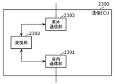
- FIG. 17 is a diagram showing an example of the configuration of the communication ECU 2300 according to the second embodiment.
- the communication ECU 2300 includes an in-vehicle communication unit 1301, a conversion unit 2302, and an out-of-vehicle communication unit 2303.
- the conversion unit 2302 converts the data that needs to be transferred among the messages received via one of the in-vehicle communication unit 1301 and the out-of-vehicle communication unit 2303 into a predetermined format, and the in-vehicle communication unit 1301 and the out-of-vehicle communication unit 2303. Send to the other side of.
- the out-of-vehicle communication unit 2303 notifies the conversion unit 2302 of the message received from the server 1400. Further, the out-of-vehicle communication unit 2303 transmits the message notified by the conversion unit 2302 to the server 1400.
- the out-of-vehicle communication unit 2303 transmits the abnormality detection result information to the server 1400 using the determined communication path. It becomes a transmitter.
- FIG. 18 is a diagram showing an example of the configuration of the charging ECU 2500 according to the second embodiment.
- the charging ECU 2500 includes an in-vehicle communication unit 2501, an activation management unit 2502, an encryption processing unit 2503, a key management unit 2504, a detection result management unit 2505, a detection result holding unit 2506, a switching unit 2507, and a charging processing unit. It is composed of 2508 and an external communication unit 2509.
- the in-vehicle communication unit 2501 communicates with other ECUs through the in-vehicle network.
- the in-vehicle communication unit 2501 notifies the encryption processing unit 2503 and the charging processing unit 2508 of the received message. Further, the in-vehicle communication unit 2501 transmits a message notified by the switching unit 2507 or the charging processing unit 2508 to another ECU.
- the activation management unit 2502 is in charge of activation processing of the charging ECU 2500 and activation processing of each function of the charging ECU 2500.
- the startup management unit 2502 notifies the encryption processing unit 2503 when it is necessary to check the validity of the startup content at the time of startup.
- the encryption processing unit 2503 verifies the MAC (message authentication code) included in the message using the key and certificate held by the key management unit 2504, and notifies the detection result management unit 2505 of the result. Further, the encryption processing unit 2503 performs a validity check at the time of activation of the device or function in response to the notification content from the activation management unit 2502, and notifies the detection result management unit 2505 of the result.
- the encryption processing unit 2503 is an example of an abnormality detection unit that detects an abnormality in the vehicle 2001.
- the key management unit 2504 holds the key and certificate used by the encryption processing unit 2503.
- the detection result management unit 2505 stores the abnormality detection result in the vehicle 2001 notified by the encryption processing unit 2503 in the detection result holding unit 2506 together with the peripheral information. Further, the detection result management unit 2505 transfers the holding contents of the detection result holding unit 2506 to the communication ECU 2300 via the in-vehicle communication unit 2501 or to the server 1400 via the out-of-vehicle communication unit 2509 (abnormality detection). Since it is transmitted as result information), the detection result status message is notified to the switching unit 2507.
- An example of the detection rule is shown in FIG. 19, and an example of the message format of the detection result status message is shown in FIG. 20.
- the detection result holding unit 2506 holds the detection result data notified by the detection result management unit 2505. Further, the detection result holding unit 2506 notifies the detection result management unit 2505 of the detection result data in response to a read instruction from the detection result management unit 2505. Since an example of the specific holding contents of the detection result holding unit 2506 is the same as that of the first embodiment, the description thereof will be omitted here.
- the switching unit 2507 When the switching unit 2507 receives notification of information to be transmitted from the detection result management unit 2505 to the server 1400, determines whether to notify the information to the communication ECU 2300 or the server 1400, and notifies the communication ECU 2300. Notifies via the in-vehicle communication unit 2501, and when notifying the server 1400, notifies via the out-of-vehicle communication unit 2509.
- the switching unit 2507 determines a communication route for transmitting the abnormality detection result information indicating the abnormality detection result in the vehicle 2001 to the server 1400 from among a plurality of communication routes based on the occurrence of a specific abnormality. This is an example.
- the switching unit 2507 transmits the abnormality detection result information to the server 1400 by collating the generated specific abnormality with the table (see FIG. 19 described later) to which the communication path is associated with each abnormality type.
- the communication path for this is determined from among a plurality of communication paths.
- the switching unit 2507 switches the communication path used for communication between the vehicle 2001 and the server 1400 to the determined communication path.
- the charge processing unit 2508 is in charge of charging the battery 2015. Further, the charge processing unit 2508 has a role of notifying the state of the battery 2015 to other ECUs via the in-vehicle communication unit 2501 and notifying the server 1400 of the charge processing execution history via the out-of-vehicle communication unit 2509.
- the out-of-vehicle communication unit 2509 communicates with the server 1400 via a charging facility (not shown) outside the vehicle.
- the out-of-vehicle communication unit 2509 notifies the charge processing unit 2508 of the received message. Further, the out-of-vehicle communication unit 2509 transmits a message notified by the switching unit 2507 or the charging processing unit 2508 to the server 1400.
- FIG. 21 shows an example of the message format of the detection result status message transmitted to the server 1400 notified by the switching unit 2507.
- the out-of-vehicle communication unit 2509 transmits the abnormality detection result information to the server 1400 using the determined communication path. It becomes a transmitter.
- FIG. 19 is a diagram showing an example of a detection rule for detecting an abnormality in a message of an in-vehicle network according to the second embodiment.
- the detection rule includes a table in which specific detection contents, error IDs corresponding to the respective detection contents, and route information corresponding to each error ID are associated with each other. There is. When an abnormality described in the table occurs, the corresponding error ID and peripheral information are stored and then transmitted to the ECU described in the route information to be the transmission destination.
- FIG. 20 is a diagram showing an example of the format of the detection result status message in the vehicle according to the second embodiment.
- the payload of the detection result status message (in other words, the detection result status message transmitted to the in-vehicle network) in the vehicle is composed of the detection result header D1101, the detection unit ID D1102, the error ID D1103, and the detection result payload D1104. Will be done. Since all the elements are the same as those in the first embodiment, the description of each item is omitted, but as shown in this figure, it is possible to put a single error ID in one message.
- FIG. 21 is a diagram showing an example of the format of the detection result status message to the outside of the vehicle according to the second embodiment.
- the payload of the detection result status message outside the vehicle includes the detection result header D1201, the vehicle ID D1202, the detection unit ID D1203, the error ID D1204, and the detection result payload. It is composed of D1205 and. Since all the elements are the same as those in the first embodiment, the description of each item is omitted, but as shown in this figure, it is possible to put a single detector ID or error ID in one message. be.
- FIG. 22 is a diagram showing an example of a sequence related to the abnormality information transmission route switching process in the second embodiment.
- the abnormality detection result information is transmitted directly from the charging ECU 2500 to the server 1400 instead of being transmitted to the communication ECU 2300.
- An example of a processing sequence (in other words, a communication path via the charging ECU 2500 is determined from a plurality of communication paths) is shown. The same processing steps as those in the first embodiment are assigned the same numbers, and the description thereof will be omitted.
- the charging ECU 2500 waits for the occurrence of an abnormality, and the communication ECU 2300 waits for the occurrence of communication (reception of a notification from the charging ECU 2500).
- the charging ECU 2500 detects the occurrence of an abnormality.
- the charging ECU 2500 determines whether or not the generated abnormality is a predetermined abnormality in the vehicle 2001, and if it is a predetermined abnormality in the vehicle 2001, proceeds to the transmission process at the time of switching the communication path. .. The details of the process will be described with reference to FIG. If the abnormality detected by the charging ECU 2500 is not a predetermined abnormality in the vehicle 2001, the process proceeds to S2104. As described above, the specific abnormality includes the abnormality in the vehicle 2001.
- the charging ECU 2500 increments the counter value related to the number of occurrences of an abnormality by one.
- the charging ECU 2500 determines whether or not the number of occurrences of an abnormality (the counter value) exceeds a predetermined number of times, and if it exceeds, the process proceeds to S2106, and if not, the process proceeds to S2101.
- the charging ECU 2500 transmits information summarizing the generated abnormality contents to the communication ECU 2300.
- FIG. 23 is a diagram showing an example of a sequence related to abnormal information communication processing according to the second embodiment.
- FIG. 23 shows an example of a processing sequence in which the charging ECU 2500 transmits the abnormality detection result information regarding the generated abnormality to the server 1400.
- the server 1400 waits for the generation of communication (reception of notification from the communication ECU 2300 or the charging ECU 2500).
- the charging ECU 2500 transmits the abnormality detection result information regarding the generated abnormality to the server 1400.
- FIG. 24 is a diagram showing an example of the configuration of the charging ECU 22500 in the first modification of the second embodiment.
- the charging ECU 22500 includes an in-vehicle communication unit 2501, an activation management unit 2502, an encryption processing unit 2503, a key management unit 2504, a detection result management unit 2505, a detection result holding unit 2506, a switching unit 22507, and a charging processing unit. It is composed of 2508, an external communication unit 2509, and a vehicle state estimation unit 22510.
- the switching unit 22507 acquires the current vehicle state from the vehicle state estimation unit 22510. Further, the switching unit 22507 receives notification of information to be transmitted from the detection result management unit 2505 to the server (for example, the server 1400). Then, the switching unit 22507 determines whether to notify the communication ECU 2300 or the server 1400 of the information to be transmitted to the server 1400 when the acquired current vehicle state corresponds to a specific vehicle state. When notifying the communication ECU 2300, the notification is made via the in-vehicle communication unit 2501, and when notifying the server 1400, the notification is made via the out-of-vehicle communication unit 2509.
- the switching unit 22507 determines a communication route for transmitting the abnormality detection result information indicating the abnormality detection result in the vehicle to the server 1400 from among a plurality of communication routes based on the occurrence of a specific abnormality and the state of the vehicle. This is an example of a decision-making part.
- the switching unit 22507 switches the communication path used for communication between the vehicle and the server 1400 to the determined communication path.
- the vehicle state estimation unit 22510 estimates the current vehicle state and then notifies the switching unit 22507 of the estimated vehicle state.
- the estimated vehicle condition is not particularly limited and is appropriately set.
- FIG. 25 is a diagram showing an example of a sequence related to anomalous information communication processing in the first modification of the second embodiment.
- FIG. 25 shows an example of a processing sequence in which the charging ECU 22500 transmits information regarding an abnormality that has occurred to the server 1400.
- the same processing steps as those in the second embodiment are assigned the same numbers, and the description thereof will be omitted.
- the charging ECU 22500 determines whether or not the vehicle state is in a predetermined state (for example, charging), and if the vehicle is being charged, it goes to S2202, and if it is not being charged, the process ends.
- a predetermined state for example, charging
- the vehicle is not connected to the charging equipment outside the vehicle, and the charging ECU 22500 is not in a state where it can communicate with the server 1400 in the first place, so that the process ends.
- the abnormality detection system may have a communication path transmission unit that transmits communication path information indicating a communication path determined from a plurality of communication paths based on the occurrence of a specific abnormality.
- the communication path transmission unit may be the external communication unit 1203 included in the IVI 1200 or the external communication unit 1303 included in the communication ECU 1300, and in the second embodiment, the external communication unit included in the charging ECU 2500. It may be the external communication unit 2303 provided in the 2509 or the communication ECU 2300.
- the transmitted communication route information may be displayed on a web browser or the like. This will be described with reference to FIG.
- FIG. 26 is a diagram showing an example of display of a communication path switched between an abnormality that has occurred in another embodiment.
- the ID, the date and time of occurrence, the content, and the communication route switched due to the occurrence of the abnormality may be displayed on a web browser or the like.
- the administrator or the like can grasp what kind of abnormality has occurred and what kind of communication path has been switched to.
- FIG. 27 is a diagram showing an example of a detailed display of a communication path switched to an abnormality that has occurred in another embodiment.
- each line (for example, the ID of each line) can be selected, and the details of the occurrence abnormality and the switched communication path corresponding to the selected line are displayed as shown in FIG. 27. May be good.
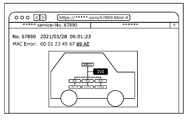
- the details of the abnormality having the ID "67890" are shown in FIG. 27, and it is shown that the abnormality is a MAC error, and specifically, the part "89 AE" is an abnormality.
- the location where the abnormality occurs in the in-vehicle network is indicated by a broken line. Further, it is indicated by highlighting the "IVI" portion that the switched communication path is a communication path via IVI.
- FIG. 28 is a diagram showing another example of the detailed display of the generated abnormality and the switched communication path in other embodiments.
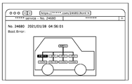
- the details of the error that occurred and the communication path that was switched may be displayed as shown in FIG. 28.
- the details of the anomaly with ID "24680" are shown in FIG. 28, indicating that the anomaly is a boot error.
- the location where the abnormality occurs in the in-vehicle network is indicated by a broken line. Further, it is indicated by highlighting the "charging ECU" portion that the switched communication path is a communication path via the charging ECU.
- the abnormality detection system may have a change unit that changes the correspondence between the type of abnormality and the communication path in the table to which the communication path is associated with each type of abnormality.
- the changing unit may be the detection result management unit 2505 included in the charging ECU 2500. This will be described with reference to FIG. 29.
- FIG. 29 is a diagram showing an example of a display for setting a correspondence relationship between an abnormality that has occurred and a communication path that can be switched in another embodiment.
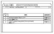
- the correspondence between the generated abnormality and the switching communication path may be displayed on a web browser or the like, or the correspondence may be set by an administrator or the like on the web browser or the like.
- the communication path to be switched when a MAC recognition error occurs is a communication path via the communication ECU, but it may be possible to change to a communication path via the charging ECU or IVI.
- the setting is changed on a web browser or the like, information indicating that fact is notified to the changed part, and the changed part changes the correspondence between the type of abnormality in the table and the communication path based on the information. You may.
- CAN-FD CAN with Flexible Data Rate
- LIN Local Interconnect Network
- MOST Media Oriented Systems Transport
- Ethernet registered trademark
- the in-vehicle network may have a network configuration in which these networks are used as sub-networks in combination.
- an ECU having a switching unit estimates a vehicle state
- a specific ECU determines the vehicle state and another ECU acquires the determined vehicle state via the in-vehicle network.
- each ECU may independently determine the vehicle state.
- the vehicle state may be determined not only during ignition ON and charging, but also at a state such as stopped, parked, accessory ON, running, low-speed running, and high-speed running.
- abnormality detection result information In the above embodiment, CAN MAC error, Automated Boot, TEE (Trusted Execution Environment) start error, and the like are shown as abnormality detection result information, but the present invention is not limited to these.
- any abnormality detection result information including various abnormality information observed by a network system or an ECU, for example, unauthorized application detection information using a system log, firewall error information, detection information by IDS (Intrusion Detection System), etc. Abnormal information may be used.
- the detection result management unit and the detection result holding unit exist in the same ECU that actually generated the abnormality detection result information
- the present invention is not limited to this.
- the detection result holding unit may exist as an EDR (Event Data Recorder) as a single ECU, or the abnormality detection result information generated by a plurality of ECUs may be aggregated in the detection result management unit of a specific ECU. good.
- the communication error may be a timeout for a certain period of time, or may be an authentication error using a certificate or the like.
- the communication path via the IVI or the charging ECU is mentioned as the communication path, but this is an example and does not exclude any communication means.
- a communication path tethering via Wi-Fi or Bluetooth using the driver's smartphone, ETC (Electronic Toll Collection System), which is communication with a communication device installed in a specific location, and DSRC (Dedicated Short Range). Range Communications) may be used.
- the switching destination ECU (communication path) is described as a physically separated ECU, but the present invention is not limited to this, and the switching destination ECU is logically another ECU. There may be.
- an ECU such as a hypervisor that integrates the functions of a plurality of ECUs may be introduced into the abnormality detection system.
- an ECU when a plurality of external interfaces are held on a plurality of virtual OSs (operating systems), each operating on a different virtual machine, a certain OS is used in response to a specific abnormality.
- the communication path may be switched from the predetermined communication path of the OS to a communication path different from the predetermined communication path of another OS.
- ECUs such as ECUs 1100a to 1100c, IVI1200, communication ECUs 1300, 11300, 2300, charging ECUs 2500, and 22500
- a plurality of ECUs are realized by a virtual environment constructed by one physical device (computer) or the like. You may be.
- FIG. 30 is a diagram showing an example of a software configuration of a virtual environment realized by a computer 1600 in another embodiment.
- the computer 1600 includes a virtual machine monitor 1601 and virtual machines 1602 to 1605.
- Virtual machine 1602 comprises virtual hardware 1610, general purpose operating system 1611 and apps 1612-1614
- virtual machine 1603 comprises virtual hardware 1620, general purpose operating system 1621 and apps 1622
- virtual machine 1604 comprises virtual hardware. It comprises 1630, a real-time operating system 1631 and an app 1632
- virtual machine 1605 includes virtual hardware 1640 and firmware 1641.
- the ECU may be realized by the software configuration of such a virtual environment.
- a virtual environment is configured by two virtual machines running a general-purpose operating system, one virtual machine running a real-time operating system, and one virtual machine running firmware is shown as an example. It's just that.
- the virtual environment may be configured, for example, only with a virtual machine running firmware, or may be configured only with a virtual machine running firmware and a virtual machine running a real-time operating system.
- each device in the above embodiment is a computer system composed of a microprocessor, ROM, RAM, hard disk unit, display unit, keyboard, mouse and the like.
- a computer program is recorded in the RAM or the hard disk unit.
- the microprocessor operates according to a computer program, each device achieves its function.
- a computer program is configured by combining a plurality of instruction codes indicating commands to a computer in order to achieve a predetermined function.
- Each device in the above embodiment may be composed of one system LSI (Large Scale Integration: large-scale integrated circuit) in part or all of the constituent elements.
- a system LSI is a super-multifunctional LSI manufactured by integrating a plurality of components on one chip, and specifically, is a computer system including a microprocessor, ROM, RAM, and the like. ..
- a computer program is recorded in the RAM. The system LSI achieves its function by operating the microprocessor according to the computer program.
- each part of the constituent elements constituting each of the above-mentioned devices may be individually integrated into one chip, or may be integrated into one chip so as to include a part or all of them.
- system LSI Although it is referred to as a system LSI here, it may be referred to as an IC, an LSI, a super LSI, or an ultra LSI due to the difference in the degree of integration. Further, the method of making an integrated circuit is not limited to the LSI, and may be realized by a dedicated circuit or a general-purpose processor. An FPGA (Field Programmable Gate Array) that can be programmed after the LSI is manufactured, or a reconfigurable processor that can reconfigure the connection and settings of the circuit cells inside the LSI may be used.
- FPGA Field Programmable Gate Array
- a part or all of the components constituting each of the above devices may be composed of an IC card or a single module that can be attached to and detached from each device.
- An IC card or module is a computer system composed of a microprocessor, ROM, RAM, and the like.
- the IC card or module may include the above-mentioned super multifunctional LSI.
- the microprocessor operates according to a computer program, the IC card or module achieves its function. This IC card or this module may have tamper resistance.
- the present disclosure can be realized not only as an abnormality detection system but also as an abnormality detection method including steps (processes) performed by each component constituting the abnormality detection system.
- FIG. 31 is a flowchart showing an example of an abnormality detection method in another embodiment.
- the anomaly detection method is an abnormality detection method in an in-vehicle network system provided with one or more ECUs mounted on the vehicle.
- the vehicle and a specific device outside the vehicle communicate with each other. Communication is possible via the route, and as shown in FIG. 31, the abnormality detection method is an abnormality detection step (S1) for detecting an abnormality in the vehicle and an abnormality detection in the vehicle based on the occurrence of a specific abnormality.
- the step in the abnormality detection method may be executed by a computer (computer system).
- the present disclosure can be realized as a computer program for causing a computer to execute a step included in the abnormality detection method or a digital signal including the program.
- the present disclosure also discloses computer programs or recording media capable of computer-readable digital signals, such as flexible disks, hard disks, CD-ROMs, MOs, DVDs, DVD-ROMs, DVD-RAMs, and BDs (Blu-ray®). ) It may be recorded on a Disc), a semiconductor memory, or the like. Further, the present disclosure may be a digital signal recorded on these recording media.
- a computer program or a digital signal may be transmitted via a telecommunication line, a wireless or wired communication line, a network typified by the Internet, data broadcasting, or the like.
- the present disclosure is a computer system including a microprocessor and a memory, and the memory may record the above-mentioned computer program, and the microprocessor may operate according to the computer program.
- a program or digital signal transferred by another independent computer system can be transferred. It may be carried out.
- the present disclosure is applicable to an in-vehicle network system including a vehicle and an external device of the vehicle that communicates with the vehicle.
Abstract
This anomaly detection system is a system in an onboard network system (1000) provided with one or more ECUs incorporated in a vehicle (1001), wherein the onboard network system (1000) allows the vehicle (1001) and a server (1400) to communicate via a plurality of communication paths, the anomaly detection system including: an anomaly detection unit that detects an anomaly in the vehicle (1001); a determination unit that determines, on the basis of the specific anomaly that occurred, a communication path, from among the plurality of communication paths, for transmitting, to the server (1400), anomaly detection results information indicating the anomaly detection results for the vehicle (1001); and an anomaly detection results transmission unit that transmits the anomaly detection results information to the server (1400) using the determined communication path.
Description
本開示は、車載ネットワークシステムにおける異常を検出するための異常検知システム及び異常検知方法に関する。
This disclosure relates to an abnormality detection system and an abnormality detection method for detecting an abnormality in an in-vehicle network system.
近年、自動車の中のシステムには、電子制御装置(ECU:Electronic Control Unit)と呼ばれる装置が多数配置されている。これらのECUをつなぐネットワークは車載ネットワークと呼ばれる。車載ネットワークには、多数の規格が存在する。その中でも最も主流な車載ネットワークの一つに、ISO11898-1で規定されているCAN(Controller Area Network)という規格が存在する。
In recent years, a large number of devices called electronic control units (ECUs) are arranged in systems in automobiles. The network connecting these ECUs is called an in-vehicle network. There are many standards for in-vehicle networks. Among them, one of the most mainstream in-vehicle networks is a standard called CAN (Controller Area Network) defined by ISO11898-1.
CANでは、通信路は2本のバスで構成され、バスに接続されているECUはノードと呼ばれる。バスに接続されている各ノードは、フレームと呼ばれるメッセージを送受信する。
In CAN, the communication path is composed of two buses, and the ECU connected to the buses is called a node. Each node connected to the bus sends and receives a message called a frame.
CANでは、送信先ノードや送信元ノードを指す識別子は存在せず、送信ノードはフレーム毎にメッセージIDと呼ばれるIDを付けて送信し、各受信ノードは予め定められたメッセージIDのみを受信する。そのため、CANのバスにECUを接続し、異常な制御コマンドを含むフレームを正規のECUになりすまして送信することで、自動車を不正に制御できてしまう脅威がある。
In CAN, there is no identifier that points to the destination node or source node, the transmission node sends with an ID called a message ID for each frame, and each receiving node receives only a predetermined message ID. Therefore, there is a threat that the automobile can be illegally controlled by connecting the ECU to the CAN bus and transmitting a frame containing an abnormal control command by pretending to be a legitimate ECU.
このような脅威に対応するため、車外にあるサーバシステムを用いて車両内で判定困難な不正なメッセージの注入を検出する方法が提案されている(例えば特許文献1)。
In order to deal with such threats, a method of detecting the injection of an illegal message that is difficult to determine in the vehicle by using a server system outside the vehicle has been proposed (for example, Patent Document 1).
しかし、上記特許文献1では、車両外にあるサーバシステムへの通信を意図的に妨害された場合や、車両外へ通信ができなくなるような異常が車両において発生した場合に、車内の異常の情報をサーバシステムへ通知できず、サーバシステムにおいて異常の適切な検知処理を実施できないといった問題が存在する。
However, in Patent Document 1, when communication to the server system outside the vehicle is intentionally disturbed or when an abnormality occurs in the vehicle that prevents communication outside the vehicle, information on the abnormality inside the vehicle occurs. Can not be notified to the server system, and there is a problem that the server system cannot appropriately detect an abnormality.
そこで、本開示は、車両内で発生した異常の情報をより確実に車両外へ通知することができる異常検知システムなどを提供することを目的とする。
Therefore, it is an object of the present disclosure to provide an abnormality detection system or the like that can more reliably notify the outside of the vehicle of information on the abnormality that has occurred inside the vehicle.
本開示の一態様である異常検知システムは、車両に搭載された1つ以上の電子制御装置が設けられた車載ネットワークシステムにおける異常検知システムであって、前記車載ネットワークシステムでは、前記車両と、前記車両の外部の特定の装置とが複数の通信経路を介して通信可能であり、前記異常検知システムは、前記車両における異常を検知する異常検知部と、特定の異常の発生に基づいて、前記車両における異常の検知結果を示す異常検知結果情報を前記特定の装置へ送信するための通信経路を、前記複数の通信経路のうちから決定する決定部と、決定された通信経路を使って前記特定の装置へ前記異常検知結果情報を送信する異常検知結果送信部と、を有することを特徴とする。
The anomaly detection system according to one aspect of the present disclosure is an anomaly detection system in an in-vehicle network system provided with one or more electronic control devices mounted on a vehicle, and in the in-vehicle network system, the vehicle and the vehicle. A specific device outside the vehicle can communicate with a specific device via a plurality of communication paths, and the abnormality detection system has an abnormality detection unit that detects an abnormality in the vehicle and the vehicle based on the occurrence of the specific abnormality. The determination unit for determining the communication path for transmitting the abnormality detection result information indicating the abnormality detection result in the above-mentioned specific device from the plurality of communication paths, and the specific communication path using the determined communication path. It is characterized by having an abnormality detection result transmitting unit for transmitting the abnormality detection result information to the apparatus.
本開示によれば、車両内で発生した異常の情報をより確実に車両外へ通知することが可能となる。
According to this disclosure, it is possible to more reliably notify the outside of the vehicle of information on abnormalities that have occurred inside the vehicle.
本開示の一態様である異常検知システムは、車両に搭載された1つ以上の電子制御装置が設けられた車載ネットワークシステムにおける異常検知システムであって、前記車載ネットワークシステムでは、前記車両と、前記車両の外部の特定の装置とが複数の通信経路を介して通信可能であり、前記異常検知システムは、前記車両における異常を検知する異常検知部と、特定の異常の発生に基づいて、前記車両における異常の検知結果を示す異常検知結果情報を前記特定の装置へ送信するための通信経路を、前記複数の通信経路のうちから決定する決定部と、決定された通信経路を使って前記特定の装置へ前記異常検知結果情報を送信する異常検知結果送信部と、を有する。
The anomaly detection system according to one aspect of the present disclosure is an anomaly detection system in an in-vehicle network system provided with one or more electronic control devices mounted on a vehicle, and in the in-vehicle network system, the vehicle and the vehicle. A specific device outside the vehicle can communicate with a specific device via a plurality of communication paths, and the abnormality detection system has an abnormality detection unit that detects an abnormality in the vehicle and the vehicle based on the occurrence of the specific abnormality. The determination unit for determining the communication path for transmitting the abnormality detection result information indicating the abnormality detection result in the above-mentioned specific device from the plurality of communication paths, and the specific communication path using the determined communication path. It has an abnormality detection result transmission unit that transmits the abnormality detection result information to the device.
これにより、車内で発生した異常に関する異常検知結果情報を車外のシステム(特定の装置)へ通知する際に、予め設定された複数の通信経路のうちのある通信経路を介した通信ができなくなるような特定の異常が発生した場合に、別の適切な通信経路が決定され、当該通信経路を使って異常検知結果情報を特定の装置へ通知することが可能となり、車両全体の安全性を担保することが可能となる。したがって、車両内で発生した異常情報をより確実に車両外へ通知することができる。
As a result, when anomaly detection result information regarding an abnormality that has occurred in the vehicle is notified to a system (specific device) outside the vehicle, communication via a certain communication path among a plurality of preset communication paths cannot be performed. When a specific abnormality occurs, another appropriate communication route is determined, and the abnormality detection result information can be notified to the specific device using the communication route, ensuring the safety of the entire vehicle. Is possible. Therefore, the abnormality information generated in the vehicle can be more reliably notified to the outside of the vehicle.
例えば、前記特定の異常は、前記車両の外部との通信の異常を含んでいてもよい。
For example, the specific abnormality may include an abnormality in communication with the outside of the vehicle.
これにより、予め設定された複数の通信経路のうちのある通信経路を介した車両の外部との通信の異常が発生した場合に、別の適切な通信経路を決定することが可能となる。
This makes it possible to determine another appropriate communication path when an abnormality occurs in communication with the outside of the vehicle via a certain communication path among a plurality of preset communication paths.
例えば、前記車両の外部との通信の異常は、前記特定の装置への前記異常検知結果情報の送信処理の異常を含んでいてもよい。
For example, the abnormality in communication with the outside of the vehicle may include an abnormality in the transmission processing of the abnormality detection result information to the specific device.
これにより、送信処理に関わる装置のみで通信経路を決定することができ、通信経路の決定にかかる時間を削減することが可能となる。
As a result, the communication route can be determined only by the device involved in the transmission process, and the time required for determining the communication route can be reduced.
例えば、前記車両の外部との通信の異常は、前記特定の装置における前記異常検知結果情報の受信処理の異常を含んでいてもよい。
For example, the abnormality in communication with the outside of the vehicle may include an abnormality in the reception processing of the abnormality detection result information in the specific device.
これにより、車両内の送信処理に関わる装置に、通信経路の決定に関わる処理を追加する必要がなく、車両におけるリソースを削減することが可能となる。
This makes it possible to reduce resources in the vehicle without having to add processing related to the determination of the communication route to the device related to the transmission processing in the vehicle.
例えば、前記特定の異常は、前記車両における異常を含んでいてもよい。
For example, the specific abnormality may include an abnormality in the vehicle.
これにより、車両外へ通信ができなくなるような異常が車両において発生した場合に、発生した異常に応じて適切な通信経路を決定することが可能となる。
This makes it possible to determine an appropriate communication route according to the occurrence of an abnormality in the vehicle that makes it impossible to communicate outside the vehicle.
例えば、前記決定部は、発生した前記特定の異常を、異常の種類ごとに通信経路が対応付けられたテーブルに照合することで、前記異常検知結果情報を前記特定の装置へ送信するための通信経路を、前記複数の通信経路のうちから決定してもよい。
For example, the determination unit collates the generated specific abnormality with a table associated with a communication path for each type of abnormality, so that the determination unit transmits the abnormality detection result information to the specific device. The route may be determined from the plurality of communication routes.
これにより、予め想定される異常に対して、例えば異常の重要度(深刻度、緊急度など)に応じた通信経路がテーブルにおいて対応付けられているため、異常の重要度に応じて柔軟に通信経路を決定することが可能となる。
As a result, for example, communication routes according to the importance of the abnormality (severity, urgency, etc.) are associated with the assumed abnormality in the table, so that communication can be flexibly performed according to the importance of the abnormality. It becomes possible to determine the route.
例えば、前記異常検知システムは、さらに、前記テーブルにおける異常の種類と通信経路との対応付けを変更する変更部を有していてもよい。
For example, the abnormality detection system may further have a change unit for changing the correspondence between the type of abnormality in the table and the communication path.
これにより、車両が出荷された後であっても、テーブルにおける異常の種類と通信経路との対応付けを変更することができる。
This makes it possible to change the correspondence between the type of abnormality in the table and the communication path even after the vehicle has been shipped.
例えば、前記複数の通信経路は、TCU(Telematics Control Unit)を介する通信経路を含んでいてもよい。
For example, the plurality of communication paths may include a communication path via a TCU (Telematics Control Unit).
これにより、テレマティクスサービスなどを利用する車両での、車両外からの異常検知が可能となり、車両全体の安全性を担保することが可能となる。
This makes it possible to detect anomalies from outside the vehicle in vehicles that use telematics services, etc., and to ensure the safety of the entire vehicle.
例えば、前記複数の通信経路は、IVI(In-Vehicle Infotainment)を介する通信経路を含んでいてもよい。
For example, the plurality of communication paths may include a communication path via IVI (In-Vehicle Infotainment).
これにより、エンターテインメントサービスなどを利用する車両での、車両外からの異常検知が可能となり、車両全体の安全性を担保することが可能となる。
This makes it possible to detect anomalies from outside the vehicle in vehicles that use entertainment services, etc., and to ensure the safety of the entire vehicle.
例えば、前記複数の通信経路は、バッテリーの充電を担当する電子制御装置を介する通信経路を含んでいてもよい。
For example, the plurality of communication paths may include a communication path via an electronic control device in charge of charging the battery.
これにより、バッテリー装置を持つ電気自動車やプラグインハイブリッド車での、車両外からの異常検知が可能となり、車両全体の安全性を担保することが可能となる。
This makes it possible to detect anomalies from outside the vehicle in electric vehicles and plug-in hybrid vehicles that have a battery device, and it is possible to ensure the safety of the entire vehicle.
例えば、前記決定部は、前記特定の異常の発生及び前記車両の状態に応じて、前記異常検知結果情報を前記特定の装置へと送信するための通信経路を、前記複数の通信経路のうちから決定してもよい。
For example, the determination unit sets a communication path for transmitting the abnormality detection result information to the specific device from among the plurality of communication paths according to the occurrence of the specific abnormality and the state of the vehicle. You may decide.
これにより、現在の車両の状態に応じた適切な通信経路の決定が可能となり、車両全体の安全性を担保することが可能となる。
This makes it possible to determine an appropriate communication route according to the current state of the vehicle, and it is possible to ensure the safety of the entire vehicle.
例えば、前記異常検知システムは、さらに、決定された通信経路を示す通信経路情報を送信する通信経路送信部を有していてもよい。
For example, the abnormality detection system may further have a communication path transmission unit that transmits communication path information indicating a determined communication path.
これにより、特定の異常の発生に応じて決定された通信経路を例えばウェブブラウザなどによって確認することができる。
This makes it possible to confirm the communication route determined according to the occurrence of a specific abnormality by, for example, a web browser.
また、本開示の一態様である異常検知方法は、車両に搭載された1つ以上の電子制御装置が設けられた車載ネットワークシステムにおける異常検知方法であって、前記車載ネットワークシステムでは、前記車両と、前記車両の外部の特定の装置とが複数の通信経路を介して通信可能であり、前記異常検知方法は、前記車両における異常を検知する異常検知ステップと、特定の異常の発生に基づいて、前記車両における異常の検知結果を示す異常検知結果情報を前記特定の装置へ送信するための通信経路を、前記複数の通信経路のうちから決定する決定ステップと、決定された通信経路を使って前記特定の装置へ前記異常検知結果情報を送信する異常検知結果送信ステップと、を含む。
Further, the abnormality detection method according to one aspect of the present disclosure is an abnormality detection method in an in-vehicle network system provided with one or more electronic control devices mounted on a vehicle, and in the in-vehicle network system, the vehicle and the vehicle. , A specific device outside the vehicle can communicate via a plurality of communication paths, and the abnormality detection method is based on an abnormality detection step for detecting an abnormality in the vehicle and the occurrence of a specific abnormality. The determination step for determining the communication path for transmitting the abnormality detection result information indicating the abnormality detection result in the vehicle to the specific device from the plurality of communication paths, and the determined communication path are used. It includes an abnormality detection result transmission step of transmitting the abnormality detection result information to a specific device.
これにより、車両内で発生した異常情報をより確実に車両外へ通知することができる異常検知方法を提供できる。
This makes it possible to provide an abnormality detection method that can more reliably notify the abnormality information generated in the vehicle to the outside of the vehicle.
以下、図面を参照しながら、本開示の実施の形態に関わる異常検知システムについて説明する。なお、以下で説明する実施の形態は、いずれも本開示の好ましい一具体例を示す。つまり、以下の実施の形態で示される数値、形状、材料、構成要素、構成要素の配置および接続形態、ステップ、ステップの順序などは、本開示の一例であり、本開示を限定する主旨ではない。
Hereinafter, the abnormality detection system related to the embodiment of the present disclosure will be described with reference to the drawings. It should be noted that all of the embodiments described below show a preferred specific example of the present disclosure. That is, the numerical values, shapes, materials, components, arrangement and connection forms of components, steps, order of steps, etc. shown in the following embodiments are examples of the present disclosure, and are not intended to limit the present disclosure. ..
本開示は、請求の範囲の記載に基づいて特定される。したがって、以下の実施の形態における構成要素のうち、本開示の最上位概念を示す独立請求項に記載されていない構成要素は、本開示の課題を達成するために必ずしも必要ではないが、より好ましい形態を構成する構成要素として説明される。
This disclosure is specified based on the description of the scope of claims. Therefore, among the components in the following embodiments, the components not described in the independent claims indicating the highest level concept of the present disclosure are not necessarily necessary for achieving the tasks of the present disclosure, but are more preferable. Described as a component constituting the form.
(実施の形態1)
[1.システムの構成]
ここでは、本開示の実施の形態1として、車載ネットワークシステム1000について図面を参照しながら説明する。 (Embodiment 1)
[1. System configuration]
Here, as the first embodiment of the present disclosure, the in-vehicle network system 1000 will be described with reference to the drawings.
[1.システムの構成]
ここでは、本開示の実施の形態1として、車載ネットワークシステム1000について図面を参照しながら説明する。 (Embodiment 1)
[1. System configuration]
Here, as the first embodiment of the present disclosure, the in-
[1.1 車載ネットワークシステム1000の全体構成]
図1は、実施の形態1における車載ネットワークシステム1000の全体構成の一例を示す図である。 [1.1 Overall configuration of in-vehicle network system 1000]
FIG. 1 is a diagram showing an example of the overall configuration of the in-vehicle network system 1000 according to the first embodiment.
図1は、実施の形態1における車載ネットワークシステム1000の全体構成の一例を示す図である。 [1.1 Overall configuration of in-vehicle network system 1000]
FIG. 1 is a diagram showing an example of the overall configuration of the in-
車載ネットワークシステム1000は、車両1001と、車両1001とネットワークを介して接続して動作するサーバ1400と、によって構成される。車載ネットワークシステム1000には、車両1001に搭載された1つ以上のECUが設けられる。また、車載ネットワークシステム1000には、異常検知システムが含まれている。
The in-vehicle network system 1000 is composed of a vehicle 1001 and a server 1400 that operates by connecting to the vehicle 1001 via a network. The in-vehicle network system 1000 is provided with one or more ECUs mounted on the vehicle 1001. Further, the in-vehicle network system 1000 includes an abnormality detection system.
異常検知システムは、プロセッサ、通信インタフェース及びメモリなどを含むコンピュータである。メモリは、ROM(Read Only Memory)及びRAM(Random Access Memory)などであり、プロセッサにより実行されるプログラムを記憶することができる。異常検知システムが有する構成要素は、メモリに格納されたプログラムを実行するプロセッサ及び通信インタフェースなどによって実現される。異常検知システムは、1つの筐体によって実現された装置であってもよい。また、異常検知システムの構成要素は、複数の装置(複数の筐体)に分散して配置されていてもよい。
The anomaly detection system is a computer that includes a processor, communication interface, memory, and so on. The memory is a ROM (Read Only Memory), a RAM (Random Access Memory), or the like, and can store a program executed by the processor. The components of the anomaly detection system are realized by a processor that executes a program stored in a memory, a communication interface, and the like. The anomaly detection system may be a device realized by one housing. Further, the components of the abnormality detection system may be distributed and arranged in a plurality of devices (a plurality of housings).
車両1001は、各種車載ネットワークにて接続される、ECU1100a、1100b及び1100cと、各ECU1100a~1100cの制御対象であるブレーキ1011、ハンドル1012及びアクセル1013と、各ECU1100a~1100cと車載ネットワークを介して通信する、IVI1200及び通信ECU1300と、から構成される。
The vehicle 1001 communicates with the ECUs 1100a, 1100b and 1100c connected by various in-vehicle networks, the brakes 1011, the handles 1012 and the accelerator 1013 which are the controlled objects of the ECUs 1100a to 1100c, and the ECUs 1100a to 1100c via the in-vehicle network. It is composed of IVI1200 and communication ECU1300.
ECU1100a~1100cは、車載ネットワークを通じて、通信メッセージを互いに送受信することで、車両の制御を実現する。例えば、車載ネットワークにはCANが使用される。以下では、ECU1100a~1100cを総合してECU1100とも呼ぶ。
The ECUs 1100a to 1100c realize control of the vehicle by transmitting and receiving communication messages to and from each other through the in-vehicle network. For example, CAN is used for in-vehicle networks. Hereinafter, the ECUs 1100a to 1100c are collectively referred to as an ECU 1100.
IVI1200は、車両1001内の状態を表示可能な表示部を備え、車両1001内の状態を示す各種情報をドライバへ提示する。また、IVI1200は、サーバ1400と通信を行い、サーバ1400と車両1001内の他のECUとのメッセージの送受信を実施する。なお、IVI1200は、サーバ1400以外の車両外の装置とも通信可能であってもよい。
The IVI1200 is provided with a display unit capable of displaying the state inside the vehicle 1001, and presents various information indicating the state inside the vehicle 1001 to the driver. Further, the IVI 1200 communicates with the server 1400 and transmits / receives a message between the server 1400 and another ECU in the vehicle 1001. The IVI1200 may be capable of communicating with devices outside the vehicle other than the server 1400.
通信ECU1300は、サーバ1400と通信を行い、サーバ1400と車両1001内の他のECUとのメッセージの送受信を実施する。通信ECU1300は、TCUの一例である。
The communication ECU 1300 communicates with the server 1400 and transmits / receives a message between the server 1400 and another ECU in the vehicle 1001. The communication ECU 1300 is an example of TCU.
サーバ1400は、遠隔より車両の安全性を担保するための監視を実施する。また、サーバ1400は、車両1001から送信されたメッセージを解析することで、車両1001内で判定困難な不正なメッセージを検出してもよい。サーバ1400は、車両1001の外部の特定の装置の一例である。
Server 1400 remotely monitors to ensure the safety of the vehicle. Further, the server 1400 may detect an illegal message that is difficult to determine in the vehicle 1001 by analyzing the message transmitted from the vehicle 1001. The server 1400 is an example of a specific device outside the vehicle 1001.
図1に示されるように、車載ネットワークシステム1000では、車両1001と、サーバ1400とが複数の通信経路を介して通信可能である。例えば、複数の通信経路は、通信ECU1300(TCU)を介する通信経路及びIVI1200を介する通信経路を含む。
As shown in FIG. 1, in the in-vehicle network system 1000, the vehicle 1001 and the server 1400 can communicate with each other via a plurality of communication paths. For example, the plurality of communication paths include a communication path via the communication ECU 1300 (TCU) and a communication path via the IVI1200.
[1.2 ECU1100の構成図]
図2は、実施の形態1におけるECU1100の構成の一例を示す図である。ECU1100は、通信部1101と、メッセージ変換部1102と、起動管理部1103と、暗号処理部1104と、鍵管理部1105と、検知結果管理部1106と、検知結果保持部1107と、から構成される。 [1.2 Configuration diagram of ECU 1100]
FIG. 2 is a diagram showing an example of the configuration of theECU 1100 according to the first embodiment. The ECU 1100 is composed of a communication unit 1101, a message conversion unit 1102, an activation management unit 1103, a cryptographic processing unit 1104, a key management unit 1105, a detection result management unit 1106, and a detection result holding unit 1107. ..
図2は、実施の形態1におけるECU1100の構成の一例を示す図である。ECU1100は、通信部1101と、メッセージ変換部1102と、起動管理部1103と、暗号処理部1104と、鍵管理部1105と、検知結果管理部1106と、検知結果保持部1107と、から構成される。 [1.2 Configuration diagram of ECU 1100]
FIG. 2 is a diagram showing an example of the configuration of the
通信部1101は、各種センサや、車載ネットワークを通じた他のECUとの通信を行う。通信部1101は、受信したメッセージやセンサ値をメッセージ変換部1102に通知する。また、通信部1101は、メッセージ変換部1102又は検知結果管理部1106より通知されたメッセージを他のECUや各種センサに送信する。
The communication unit 1101 communicates with various sensors and other ECUs via the in-vehicle network. The communication unit 1101 notifies the message conversion unit 1102 of the received message and the sensor value. Further, the communication unit 1101 transmits the message notified by the message conversion unit 1102 or the detection result management unit 1106 to other ECUs and various sensors.
メッセージ変換部1102は、通信部1101から通知されたセンサ値を車載ネットワークのフォーマットに基づき変換し、通信部1101を介して、他のECUへ送信する。また、メッセージ変換部1102は、通信部1101より受信した通信メッセージをセンサ値や設定情報に変換し、通信部1101を介して、各種センサに送信する。また、メッセージ変換部1102は、受信したメッセージを暗号処理部1104へ通知する。
The message conversion unit 1102 converts the sensor value notified from the communication unit 1101 based on the format of the vehicle-mounted network, and transmits it to another ECU via the communication unit 1101. Further, the message conversion unit 1102 converts the communication message received from the communication unit 1101 into sensor values and setting information, and transmits the communication message to various sensors via the communication unit 1101. Further, the message conversion unit 1102 notifies the encryption processing unit 1104 of the received message.
起動管理部1103は、ECU1100の起動処理と、ECU1100の各機能の起動処理を担当する。起動管理部1103は、起動時に起動内容の正当性チェックが必要な場合は、暗号処理部1104へ通知する。
The activation management unit 1103 is in charge of the activation process of the ECU 1100 and the activation process of each function of the ECU 1100. The activation management unit 1103 notifies the encryption processing unit 1104 when it is necessary to check the validity of the activation contents at the time of activation.
暗号処理部1104は、鍵管理部1105の保持する鍵や証明書を用いて、メッセージに含まれるMAC(メッセージ認証符号)の検証を行い、その結果を検知結果管理部1106へと通知する。また、暗号処理部1104は、起動管理部1103からの通知内容に対応して、装置や機能の起動時の正当性チェックを行い、その結果を検知結果管理部1106へと通知する。暗号処理部1104は、車両1001における異常(例えば、攻撃による異常又は故障による異常等)を検知する異常検知部の一例である。
The encryption processing unit 1104 verifies the MAC (message authentication code) included in the message using the key and certificate held by the key management unit 1105, and notifies the detection result management unit 1106 of the result. Further, the encryption processing unit 1104 performs a validity check at the time of activation of the device or function in response to the notification content from the activation management unit 1103, and notifies the detection result management unit 1106 of the result. The encryption processing unit 1104 is an example of an abnormality detection unit that detects an abnormality in the vehicle 1001 (for example, an abnormality due to an attack or an abnormality due to a failure).
鍵管理部1105は、暗号処理部1104で使用する鍵や証明書を保持する。
The key management unit 1105 holds the key and certificate used by the encryption processing unit 1104.
検知結果管理部1106は、暗号処理部1104から通知された車両1001における異常の検知結果を、周辺情報とともに検知結果保持部1107へ格納する。また、検知結果管理部1106は、検知結果保持部1107の保持内容を、通信部1101を介して通信ECU1300へ、検知結果状態メッセージ(異常検知結果情報とも呼ぶ)として送信する。車両1001における異常を検知する際の検知ルールの一例については図3に、検知結果状態メッセージのメッセージフォーマットの一例については図4に、それぞれ示す。
The detection result management unit 1106 stores the abnormality detection result in the vehicle 1001 notified from the encryption processing unit 1104 in the detection result holding unit 1107 together with the peripheral information. Further, the detection result management unit 1106 transmits the holding contents of the detection result holding unit 1107 to the communication ECU 1300 via the communication unit 1101 as a detection result status message (also referred to as abnormality detection result information). FIG. 3 shows an example of a detection rule for detecting an abnormality in the vehicle 1001, and FIG. 4 shows an example of a message format of a detection result status message.
検知結果保持部1107は、検知結果管理部1106より通知の受けた検知結果データを保持する。また、検知結果保持部1107は、検知結果管理部1106からの読み出し指示に応じて、当該検知結果データを検知結果管理部1106へ通知する。検知結果保持部1107の具体的な保持内容の一例については、図5に示す。
The detection result holding unit 1107 holds the detection result data notified by the detection result management unit 1106. Further, the detection result holding unit 1107 notifies the detection result management unit 1106 of the detection result data in response to a read instruction from the detection result management unit 1106. An example of the specific holding contents of the detection result holding unit 1107 is shown in FIG.
[1.3 検知ルールの一例]
図3は、実施の形態1における車載ネットワークのメッセージの異常を検知するための検知ルールの一例を示す図である。図3に示されるように、検知ルールには、具体的な検知内容と、それぞれの検知内容に対応するエラーIDとが対応付けられたテーブルが含まれている。テーブルに記載された異常が発生した場合に、該当するエラーIDと周辺情報とが、検知結果として保存処理される。 [1.3 An example of detection rule]
FIG. 3 is a diagram showing an example of a detection rule for detecting an abnormality in a message of an in-vehicle network according to the first embodiment. As shown in FIG. 3, the detection rule includes a table in which specific detection contents and error IDs corresponding to the respective detection contents are associated with each other. When an abnormality described in the table occurs, the corresponding error ID and peripheral information are saved as a detection result.
[1.4 車内への検知結果状態メッセージのフォーマットの一例]
図4は、実施の形態1における車内への検知結果状態メッセージのフォーマットの一例を示す図である。車内への検知結果状態メッセージ(言い換えると車載ネットワークに送信される検知結果状態メッセージ)のペイロードは、検知結果ヘッダーD1101と、検知部ID D1102と、エラーID D1103と、検知結果ペイロードD1104と、によって構成される。 [1.4 Example of format of detection result status message in the car]
FIG. 4 is a diagram showing an example of the format of the detection result status message in the vehicle according to the first embodiment. The payload of the detection result status message (in other words, the detection result status message transmitted to the in-vehicle network) in the vehicle is composed of the detection result header D1101, the detection unit ID D1102, the error ID D1103, and the detection result payload D1104. Will be done.
検知結果ヘッダーD1101は、以降に続くデータの種別とその数を示す値を格納するための領域である。予め決められた番号を先頭に入れておくことで、検知結果ヘッダーD1101は、以降のデータが検知結果状態を示すメッセージであることを表すと同時に、その中身を受信者に伝える役割を担う。
The detection result header D1101 is an area for storing a value indicating the type and number of data that follow. By putting a predetermined number at the beginning, the detection result header D1101 indicates that the subsequent data is a message indicating the detection result status, and at the same time, plays a role of transmitting the contents to the receiver.
検知部ID D1102は、ECU1100a、ECU1100b及びECU1100cの中にある異常検知部を特定するためにユニークに設定された数字を格納する。
The detection unit ID D1102 stores a number uniquely set for identifying the abnormality detection unit in the ECU 1100a, ECU 1100b, and ECU 1100c.
エラーID D1103は、検知部ID D1102で特定した異常検知部からの検知結果に含まれる異常の種別を示す。
The error ID D1103 indicates the type of abnormality included in the detection result from the abnormality detection unit specified by the detection unit ID D1102.
検知結果ペイロードD1104は、エラー周辺情報となる情報を示す。
The detection result payload D1104 indicates information that serves as error peripheral information.
なお、本図に示すとおり、複数のエラーIDを一つのメッセージに入れることも可能である。
As shown in this figure, it is possible to put multiple error IDs in one message.
[1.5 検知結果管理テーブルの一例]
図5は、実施の形態1における検知結果管理テーブルの一例を示す図である。例えば、検知結果管理部1106は、車内への検知結果状態メッセージに基づいて検知結果管理テーブルを作成し、検知結果保持部1107に格納する。検知結果管理テーブルは、暗号処理部1104によって検知された異常に該当するエラーIDと、その異常の発生時刻と、周辺情報となる検知結果ペイロードデータと、によって構成されている。 [1.5 Example of detection result management table]
FIG. 5 is a diagram showing an example of a detection result management table according to the first embodiment. For example, the detectionresult management unit 1106 creates a detection result management table based on the detection result status message in the vehicle, and stores it in the detection result holding unit 1107. The detection result management table is composed of an error ID corresponding to the abnormality detected by the encryption processing unit 1104, a time when the abnormality occurs, and detection result payload data as peripheral information.
図5は、実施の形態1における検知結果管理テーブルの一例を示す図である。例えば、検知結果管理部1106は、車内への検知結果状態メッセージに基づいて検知結果管理テーブルを作成し、検知結果保持部1107に格納する。検知結果管理テーブルは、暗号処理部1104によって検知された異常に該当するエラーIDと、その異常の発生時刻と、周辺情報となる検知結果ペイロードデータと、によって構成されている。 [1.5 Example of detection result management table]
FIG. 5 is a diagram showing an example of a detection result management table according to the first embodiment. For example, the detection
[1.6 IVI1200の構成図]
図6は、実施の形態1におけるIVI1200の構成の一例を示す図である。IVI1200は、車内通信部1201と、変換部1202と、車外通信部1203と、表示部1204と、から構成される。 [Structure diagram of 1.6 IVI1200]
FIG. 6 is a diagram showing an example of the configuration of IVI1200 according to the first embodiment. The IVI1200 is composed of an in-vehicle communication unit 1201, a conversion unit 1202, an out-of-vehicle communication unit 1203, and a display unit 1204.
図6は、実施の形態1におけるIVI1200の構成の一例を示す図である。IVI1200は、車内通信部1201と、変換部1202と、車外通信部1203と、表示部1204と、から構成される。 [Structure diagram of 1.6 IVI1200]
FIG. 6 is a diagram showing an example of the configuration of IVI1200 according to the first embodiment. The IVI1200 is composed of an in-
車内通信部1201は、車内の他ECUより受信したメッセージを変換部1202へと通知する。また、車内通信部1201は、変換部1202より通知されたメッセージを車内の他ECUへと送信する。さらに、車内通信部1201は、ドライバへ通知が必要な情報を、表示部1204へ通知する。
The in-vehicle communication unit 1201 notifies the conversion unit 1202 of a message received from another ECU in the vehicle. Further, the in-vehicle communication unit 1201 transmits the message notified by the conversion unit 1202 to other ECUs in the vehicle. Further, the in-vehicle communication unit 1201 notifies the display unit 1204 of the information that needs to be notified to the driver.
変換部1202は、車内通信部1201及び車外通信部1203の一方を介して受信したメッセージのうち、転送が必要となるデータを予め決められたフォーマットへ変換し、車内通信部1201及び車外通信部1203の他方へと送信する。
The conversion unit 1202 converts the data that needs to be transferred from the messages received via one of the in-vehicle communication unit 1201 and the out-of-vehicle communication unit 1203 into a predetermined format, and the in-vehicle communication unit 1201 and the out-of-vehicle communication unit 1203. Send to the other side of.
車外通信部1203は、サーバ1400より受信したメッセージを変換部1202へと通知する。また、車外通信部1203は、変換部1202より通知されたメッセージをサーバ1400へと送信する。さらに、車外通信部1203は、ドライバへ通知が必要な情報を、表示部1204へ通知する。車外通信部1203は、複数の通信経路のうちから、IVI1200とサーバ1400との通信経路が決定された場合、決定された通信経路を使ってサーバ1400へ異常検知結果情報を送信する異常検知結果送信部となる。
The out-of-vehicle communication unit 1203 notifies the conversion unit 1202 of the message received from the server 1400. Further, the out-of-vehicle communication unit 1203 transmits the message notified by the conversion unit 1202 to the server 1400. Further, the out-of-vehicle communication unit 1203 notifies the display unit 1204 of the information that needs to be notified to the driver. When the communication route between the IVI 1200 and the server 1400 is determined from the plurality of communication routes, the out-of-vehicle communication unit 1203 transmits the abnormality detection result information to the server 1400 using the determined communication route. Become a department.
表示部1204は、車内通信部1201と、車外通信部1203と、から情報を通知され、通知された情報に基づいてドライバに必要な情報を提示する。
The display unit 1204 is notified of information from the in-vehicle communication unit 1201 and the out-of-vehicle communication unit 1203, and presents necessary information to the driver based on the notified information.
[1.7 通信ECU1300の構成図]
図7は、実施の形態1における通信ECU1300の構成の一例を示す図である。通信ECU1300は、車内通信部1301と、変換部1302と、車外通信部1303と、切替部1304と、から構成される。 [1.7 Configuration diagram of communication ECU 1300]
FIG. 7 is a diagram showing an example of the configuration of thecommunication ECU 1300 according to the first embodiment. The communication ECU 1300 includes an in-vehicle communication unit 1301, a conversion unit 1302, an out-of-vehicle communication unit 1303, and a switching unit 1304.
図7は、実施の形態1における通信ECU1300の構成の一例を示す図である。通信ECU1300は、車内通信部1301と、変換部1302と、車外通信部1303と、切替部1304と、から構成される。 [1.7 Configuration diagram of communication ECU 1300]
FIG. 7 is a diagram showing an example of the configuration of the
車内通信部1301は、車内の他ECUより受信したメッセージを変換部1302へと通知する。また、車内通信部1301は、変換部1302より通知されたメッセージを車内の他ECUへと送信する。
The in-vehicle communication unit 1301 notifies the conversion unit 1302 of a message received from another ECU in the vehicle. Further, the in-vehicle communication unit 1301 transmits the message notified by the conversion unit 1302 to other ECUs in the vehicle.
変換部1302は、車内通信部1301及び車外通信部1303の一方を介して受信したメッセージのうち、転送が必要となるデータを予め決められたフォーマットへ変換し、車内通信部1301及び車外通信部1303の他方へと送信する。また、変換部1302は、切替部1304からの通知を受け、通知された情報を変換した上で車内通信部1301へ通知する。
The conversion unit 1302 converts the data that needs to be transferred among the messages received via one of the in-vehicle communication unit 1301 and the out-of-vehicle communication unit 1303 into a predetermined format, and the in-vehicle communication unit 1301 and the out-of-vehicle communication unit 1303. Send to the other side of. Further, the conversion unit 1302 receives the notification from the switching unit 1304, converts the notified information, and then notifies the in-vehicle communication unit 1301.
車外通信部1303は、サーバ1400より受信したメッセージを変換部1302へと通知する。また、車外通信部1303は、変換部1302より通知されたメッセージをサーバ1400へと送信する。また、車外通信部1303は、通信エラーが発生した場合に、サーバ1400へ送信するべき情報(具体的には、検知結果状態メッセージ(異常検知結果情報))を切替部1304へ通知する。サーバ1400へ送信される検知結果状態メッセージのメッセージフォーマットの一例については図8に示す。車外通信部1303は、複数の通信経路のうちから、通信ECU1300とサーバ1400との通信経路が決定された場合、決定された通信経路を使ってサーバ1400へ異常検知結果情報を送信する異常検知結果送信部となる。
The out-of-vehicle communication unit 1303 notifies the conversion unit 1302 of the message received from the server 1400. Further, the out-of-vehicle communication unit 1303 transmits the message notified by the conversion unit 1302 to the server 1400. Further, the out-of-vehicle communication unit 1303 notifies the switching unit 1304 of information to be transmitted to the server 1400 (specifically, a detection result status message (abnormality detection result information)) when a communication error occurs. FIG. 8 shows an example of the message format of the detection result status message transmitted to the server 1400. When the communication path between the communication ECU 1300 and the server 1400 is determined from the plurality of communication paths, the out-of-vehicle communication unit 1303 transmits the abnormality detection result information to the server 1400 using the determined communication path. It becomes a transmitter.
切替部1304は、車外通信部1303よりサーバ1400へ送信するべき情報の通知を受け、現状サーバ1400との通信に用いている通信経路とは他の通信経路を用いたサーバ1400との通信が可能な車外通信部を持つECUへ、サーバ1400へ送信するべき情報を通知するために、変換部1302へ当該情報を通知する。切替部1304は、特定の異常の発生に基づいて、車両1001における異常の検知結果を示す異常検知結果情報をサーバ1400へ送信するための通信経路を、複数の通信経路のうちから決定する決定部の一例である。切替部1304によって、車両1001とサーバ1400との通信に用いられる通信経路が、決定された通信経路に切り替えられる。
The switching unit 1304 receives notification of information to be transmitted to the server 1400 from the out-of-vehicle communication unit 1303, and can communicate with the server 1400 using a communication path different from the communication path currently used for communication with the server 1400. In order to notify the ECU having the external communication unit of the information to be transmitted to the server 1400, the conversion unit 1302 is notified of the information. The switching unit 1304 determines a communication route for transmitting the abnormality detection result information indicating the abnormality detection result in the vehicle 1001 to the server 1400 from among a plurality of communication routes based on the occurrence of a specific abnormality. This is an example. The switching unit 1304 switches the communication path used for communication between the vehicle 1001 and the server 1400 to the determined communication path.
[1.8 車外への検知結果状態メッセージのフォーマットの一例]
図8は、実施の形態1における車外への検知結果状態メッセージのフォーマットの一例を示す図である。車外への検知結果状態メッセージ(言い換えるとサーバ1400へ送信される検知結果状態メッセージ)のペイロードは、検知結果ヘッダーD1201と、車両ID D1202と、検知部ID D1203と、エラーID D1204と、検知結果ペイロードD1205と、によって構成される。 [1.8 Example of format of detection result status message outside the vehicle]
FIG. 8 is a diagram showing an example of the format of the detection result status message to the outside of the vehicle according to the first embodiment. The payload of the detection result status message outside the vehicle (in other words, the detection result status message transmitted to the server 1400) includes the detection result header D1201, the vehicle ID D1202, the detection unit ID D1203, the error ID D1204, and the detection result payload. It is composed of D1205 and.
検知結果ヘッダーD1201は、以降に続くデータの種別とその数を示す値を格納するための領域である。予め決められた番号を先頭に入れておくことで、検知結果ヘッダーD1201は、以降のデータが検知結果状態を示すメッセージであることを表すと同時に、その中身を受信者に伝える役割を担う。
The detection result header D1201 is an area for storing a value indicating the type and number of data that follow. By putting a predetermined number at the beginning, the detection result header D1201 indicates that the subsequent data is a message indicating the detection result status, and at the same time, plays a role of transmitting the contents to the receiver.
車両ID D1202は、車両1001を特定するためにユニークに設定された数字を格納する。
The vehicle ID D1202 stores a number uniquely set to identify the vehicle 1001.
検知部ID D1203は、ECU1100a、ECU1100b及びECU1100cの中にある異常検知部を特定するためにユニークに設定された数字を格納する。
The detection unit ID D1203 stores a number uniquely set for identifying the abnormality detection unit in the ECU 1100a, ECU 1100b, and ECU 1100c.
エラーID D1204は、検知部ID D1203で特定した異常検知部からの検知結果に含まれる異常の種別を示す、エラーIDを示す。
The error ID D1204 indicates an error ID indicating the type of abnormality included in the detection result from the abnormality detection unit identified by the detection unit ID D1203.
検知結果ペイロードD1205は、検知結果状態を判定した結果を示す。
The detection result payload D1205 indicates the result of determining the detection result status.
車外への検知結果状態メッセージは、サーバ1400がどの車両からのメッセージであるかを特定するために、車内への検知結果状態メッセージに車両ID D1202が追加されたものとなっている。
The detection result status message to the outside of the vehicle is the one in which the vehicle ID D1202 is added to the detection result status message to the inside of the vehicle in order to specify from which vehicle the server 1400 is the message.
なお、本図に示すとおり、複数の検知部IDや、エラーIDを一つのメッセージに入れることも可能である。
As shown in this figure, it is possible to put multiple detector IDs and error IDs in one message.
[1.9 サーバ1400の構成図]
図9は、実施の形態1におけるサーバ1400の構成の一例を示す図である。サーバ1400は、通信部1401と、車両管理部1402と、から構成される。 [1.9 Configuration of Server 1400]
FIG. 9 is a diagram showing an example of the configuration of theserver 1400 according to the first embodiment. The server 1400 includes a communication unit 1401 and a vehicle management unit 1402.
図9は、実施の形態1におけるサーバ1400の構成の一例を示す図である。サーバ1400は、通信部1401と、車両管理部1402と、から構成される。 [1.9 Configuration of Server 1400]
FIG. 9 is a diagram showing an example of the configuration of the
通信部1401は、車両1001との通信を行い、受信したメッセージを車両管理部1402へと通知する。また、通信部1401は、車両管理部1402から通知された内容を、車両1001へと送信する。
The communication unit 1401 communicates with the vehicle 1001 and notifies the vehicle management unit 1402 of the received message. Further, the communication unit 1401 transmits the content notified from the vehicle management unit 1402 to the vehicle 1001.
車両管理部1402は、通信部1401を介して、車両1001と通信を行い、車両1001内の情報を管理する。例えば、車両管理部1402は、車両1001から送信されたメッセージを解析することで、不正なメッセージを検出してもよい。
The vehicle management unit 1402 communicates with the vehicle 1001 via the communication unit 1401 and manages the information in the vehicle 1001. For example, the vehicle management unit 1402 may detect an invalid message by analyzing the message transmitted from the vehicle 1001.
[1.10 異常情報通信処理シーケンスの一例]
図10は、実施の形態1における異常情報通信処理に関するシーケンスの一例を示す図である。図10では、ECU1100が、異常情報を集約し、通信ECU1300へ伝えるシーケンスの一例を示している。 [1.10 Example of abnormal information communication processing sequence]
FIG. 10 is a diagram showing an example of a sequence related to abnormal information communication processing according to the first embodiment. FIG. 10 shows an example of a sequence in which theECU 1100 aggregates abnormality information and transmits it to the communication ECU 1300.
図10は、実施の形態1における異常情報通信処理に関するシーケンスの一例を示す図である。図10では、ECU1100が、異常情報を集約し、通信ECU1300へ伝えるシーケンスの一例を示している。 [1.10 Example of abnormal information communication processing sequence]
FIG. 10 is a diagram showing an example of a sequence related to abnormal information communication processing according to the first embodiment. FIG. 10 shows an example of a sequence in which the
(S1101)ECU1100は、異常の発生を待機し、通信ECU1300は、通信の発生(ECU1100からの通知の受信)を待機する。
(S1101) The ECU 1100 waits for the occurrence of an abnormality, and the communication ECU 1300 waits for the occurrence of communication (reception of a notification from the ECU 1100).
(S1102)車両1001において異常が発生し、ECU1100は、異常を検知する。
(S1102) An abnormality occurs in the vehicle 1001, and the ECU 1100 detects the abnormality.
(S1103)ECU1100は、当該異常の発生回数を示すカウンタ値を1つインクリメントする。
(S1103) The ECU 1100 increments the counter value indicating the number of times the abnormality has occurred by one.
(S1104)ECU1100は、当該異常のカウンタ値が予め規定された回数を超えたかどうか(つまり、当該異常が規定数発生したかどうか)の判定を行い、超えた場合はS1105へ、超えていない場合はS1101へそれぞれ進む。規定された回数は、例えば、異常の種別ごとに設定される。設定される回数は特に限定されないが、例えば、異常の種別に応じて設定される。
(S1104) The ECU 1100 determines whether or not the counter value of the abnormality exceeds a predetermined number of times (that is, whether or not the specified number of abnormalities have occurred). Proceed to S1101 respectively. The specified number of times is set for each type of abnormality, for example. The number of times to be set is not particularly limited, but is set according to, for example, the type of abnormality.
(S1105)ECU1100は、発生した異常の内容を集約した情報(異常検知結果情報)を通信ECU1300へ送信する。
(S1105) The ECU 1100 transmits information (abnormality detection result information) that aggregates the contents of the generated abnormality to the communication ECU 1300.
(S1106)ECU1100は、当該異常のカウンタ値をリセットする。
(S1106) The ECU 1100 resets the counter value of the abnormality.
(S1107)ECU1100は、一連の処理を完了し、S1101へ戻る。
(S1107) The ECU 1100 completes a series of processes and returns to S1101.
[1.11 異常情報送信経路切替処理シーケンスの一例]
図11は、実施の形態1における異常情報送信経路切替処理に関するシーケンスの一例を示す図である。図11では、通信ECU1300が、異常検知結果情報をサーバ1400へ送信する際に、特定の異常として送信エラーが発生した場合に、通信経路を、IVI1200を介する通信経路に切り替えて(言い換えると、複数の通信経路のうちからIVI1200を介する通信経路を決定して)、IVI1200から異常検知結果情報を送信する処理のシーケンスの一例を示す。 [1.11 Example of error information transmission route switching processing sequence]
FIG. 11 is a diagram showing an example of a sequence related to the abnormality information transmission route switching process in the first embodiment. In FIG. 11, when thecommunication ECU 1300 transmits the abnormality detection result information to the server 1400 and a transmission error occurs as a specific abnormality, the communication path is switched to the communication path via the IVI1200 (in other words, a plurality of). An example of a sequence of processing for transmitting abnormality detection result information from IVI1200 (determining a communication path via IVI1200) is shown.
図11は、実施の形態1における異常情報送信経路切替処理に関するシーケンスの一例を示す図である。図11では、通信ECU1300が、異常検知結果情報をサーバ1400へ送信する際に、特定の異常として送信エラーが発生した場合に、通信経路を、IVI1200を介する通信経路に切り替えて(言い換えると、複数の通信経路のうちからIVI1200を介する通信経路を決定して)、IVI1200から異常検知結果情報を送信する処理のシーケンスの一例を示す。 [1.11 Example of error information transmission route switching processing sequence]
FIG. 11 is a diagram showing an example of a sequence related to the abnormality information transmission route switching process in the first embodiment. In FIG. 11, when the
(S1201)通信ECU1300は、通信の発生(ECU1100からの通知の受信)を待機し、IVI1200は、通信の発生(通信ECU1300からの通知の受信)を待機し、サーバ1400は、通信の発生(通信ECU1300又はIVI1200からの通知の受信)を待機する。
(S1201) The communication ECU 1300 waits for the generation of communication (receipt of notification from the ECU 1100), the IVI1200 waits for the generation of communication (reception of notification from the communication ECU 1300), and the server 1400 waits for the generation of communication (communication). (Reception of notification from ECU 1300 or IVI1200) is on standby.
(S1202)通信ECU1300は、受信した異常検知結果情報を、サーバ1400へ送信する。
(S1202) The communication ECU 1300 transmits the received abnormality detection result information to the server 1400.
(S1203)通信ECU1300は、特定の異常として送信エラーが発生したかどうかを確認し、発生していない場合は正常終了し、発生した場合はS1204へ進む。このように、例えば、特定の異常は、車両1001の外部(例えばサーバ1400)との通信の異常を含み、車両の外部との通信の異常は、サーバ1400への異常検知結果情報の送信処理の異常を含む。
(S1203) The communication ECU 1300 confirms whether or not a transmission error has occurred as a specific abnormality, and if it does not occur, the process ends normally, and if it does occur, the process proceeds to S1204. As described above, for example, the specific abnormality includes the abnormality of communication with the outside of the vehicle 1001 (for example, the server 1400), and the abnormality of the communication with the outside of the vehicle is the process of transmitting the abnormality detection result information to the server 1400. Including abnormalities.
(S1204)通信ECU1300は、送信のリトライ回数に関するカウンタ値を1つインクリメントする。
(S1204) The communication ECU 1300 increments the counter value related to the number of transmission retries by one.
(S1205)通信ECU1300は、送信のリトライ回数(上記カウンタ値)が規定の回数を超えたかどうかを確認し、超えた場合はS1206へ、超えていない場合はS1202へ進む。規定の回数は特に限定されず、適宜設定される。
(S1205) The communication ECU 1300 confirms whether or not the number of transmission retries (counter value above) exceeds the specified number, and if it exceeds, proceeds to S1206, and if not, proceeds to S1202. The specified number of times is not particularly limited and is set as appropriate.
(S1206)通信ECU1300は、送信のリトライに関するカウンタ値をリセットする。
(S1206) The communication ECU 1300 resets the counter value related to the retry of transmission.
(S1207)通信ECU1300は、サーバ1400へ送信しようとしていた異常検知結果情報を別通信ECU(ここではIVI1200)へ通知する。
(S1207) The communication ECU 1300 notifies another communication ECU (here, IVI1200) of the abnormality detection result information that was about to be transmitted to the server 1400.
(S1208)IVI1200は、通信ECU1300から受信した異常検知結果情報を、サーバ1400へ送信する。
(S1208) The IVI1200 transmits the abnormality detection result information received from the communication ECU 1300 to the server 1400.
(実施の形態1の効果)
実施の形態1で示した車載ネットワークシステム1000では、車内で発生した異常に関する情報を車外のシステム(例えばサーバ1400)へ通知する際に、車両1001のネットワークシステム内の車外との通信を担当するECU(例えば通信ECU1300)の通信に異常が発生した場合にも、予め別の車外通信ECU(例えばIVI1200)による通信経路を代替として設定しておくことで、異常に関する情報を適切に車外のシステムへ通知することが可能となり、車両全体の安全性を担保することが可能となる。 (Effect of Embodiment 1)
In the in-vehicle network system 1000 shown in the first embodiment, an ECU that is in charge of communication with the outside of the vehicle in the network system of the vehicle 1001 when notifying an information on an abnormality occurring in the vehicle to a system outside the vehicle (for example, a server 1400). Even if an abnormality occurs in the communication of (for example, communication ECU 1300), by setting a communication path by another out-of-vehicle communication ECU (for example, IVI1200) as an alternative in advance, information on the abnormality is appropriately notified to the system outside the vehicle. It becomes possible to ensure the safety of the entire vehicle.
実施の形態1で示した車載ネットワークシステム1000では、車内で発生した異常に関する情報を車外のシステム(例えばサーバ1400)へ通知する際に、車両1001のネットワークシステム内の車外との通信を担当するECU(例えば通信ECU1300)の通信に異常が発生した場合にも、予め別の車外通信ECU(例えばIVI1200)による通信経路を代替として設定しておくことで、異常に関する情報を適切に車外のシステムへ通知することが可能となり、車両全体の安全性を担保することが可能となる。 (Effect of Embodiment 1)
In the in-
(実施の形態1の変形例1)
実施の形態1で示した車載ネットワークシステム1000では、車両1001のネットワークシステム内の車外通信を担当するECUが通信異常を検知することで、適切な通信経路を決定する例について説明したが、車外のシステムが通信異常を判断し、通信経路を変更するとしても良い。なお、実施の形態1と同様の図面については説明を省略し、ここでは構成の異なるサーバ11400について主に説明する。 (Modification 1 of Embodiment 1)
In the in-vehicle network system 1000 shown in the first embodiment, an example in which the ECU in charge of the out-of-vehicle communication in the network system of the vehicle 1001 determines an appropriate communication route by detecting a communication abnormality has been described. The system may determine the communication abnormality and change the communication path. The same drawings as those in the first embodiment will be omitted, and here, the server 11400 having a different configuration will be mainly described.
実施の形態1で示した車載ネットワークシステム1000では、車両1001のネットワークシステム内の車外通信を担当するECUが通信異常を検知することで、適切な通信経路を決定する例について説明したが、車外のシステムが通信異常を判断し、通信経路を変更するとしても良い。なお、実施の形態1と同様の図面については説明を省略し、ここでは構成の異なるサーバ11400について主に説明する。 (
In the in-
[1.12 サーバ11400の構成図]
図12は、実施の形態1の変形例1におけるサーバ11400の構成の一例を示す図である。サーバ11400は、通信部11401と、車両管理部1402と、切替部11403から構成される。なお、実施の形態1と同様の構成は、同一の番号を付与した上で説明を省略する。 [1.12 Configuration of Server 11400]
FIG. 12 is a diagram showing an example of the configuration of theserver 11400 in the first modification of the first embodiment. The server 11400 includes a communication unit 11401, a vehicle management unit 1402, and a switching unit 11403. In the same configuration as in the first embodiment, the same number is assigned and the description thereof will be omitted.
図12は、実施の形態1の変形例1におけるサーバ11400の構成の一例を示す図である。サーバ11400は、通信部11401と、車両管理部1402と、切替部11403から構成される。なお、実施の形態1と同様の構成は、同一の番号を付与した上で説明を省略する。 [1.12 Configuration of Server 11400]
FIG. 12 is a diagram showing an example of the configuration of the
通信部11401は、車両1001との通信を行い、受信したメッセージを車両管理部1402へと通知する。また、通信部11401は、車両管理部1402から通知された内容を、車両1001へと送信する。また、通信部11401は、通信エラーが発生した場合に、切替部11403へと通知する。
The communication unit 11401 communicates with the vehicle 1001 and notifies the vehicle management unit 1402 of the received message. Further, the communication unit 11401 transmits the content notified from the vehicle management unit 1402 to the vehicle 1001. Further, the communication unit 11401 notifies the switching unit 11403 when a communication error occurs.
切替部11403は、通信部11401より通知を受け、現状車両との通信に用いている通信経路とは他の通信経路を用いたサーバ11400との通信が可能な車外通信部を持つECUと通信するために、通信部11401へ通知する。切替部11403は、特定の異常の発生に基づいて、車両における異常の検知結果を示す異常検知結果情報をサーバ11400へ送信するための通信経路を、複数の通信経路のうちから決定する決定部の一例である。切替部11403によって、車両とサーバ11400との通信に用いられる通信経路が、決定された通信経路に切り替えられる。
The switching unit 11403 receives a notification from the communication unit 11401 and communicates with an ECU having an out-of-vehicle communication unit capable of communicating with the server 11400 using a communication path other than the communication path currently used for communication with the vehicle. Therefore, the communication unit 11401 is notified. The switching unit 11403 is a determination unit that determines a communication path for transmitting the abnormality detection result information indicating the abnormality detection result in the vehicle to the server 11400 based on the occurrence of a specific abnormality from among a plurality of communication paths. This is just one example. The switching unit 11403 switches the communication path used for communication between the vehicle and the server 11400 to the determined communication path.
[1.13 異常情報送信経路切替処理シーケンスの一例]
図13は、実施の形態1の変形例1における異常情報送信経路切替処理に関するシーケンスの一例を示す図である。図13では、サーバ11400が、異常検知結果情報を通信ECU1300へリクエストする際に、特定の異常として通信エラーが発生した場合に、リクエスト先をIVI1200に切り替えて(言い換えると、複数の通信経路のうちからIVI1200を介する通信経路を決定して)、IVI1200から異常検知結果情報を送信する処理のシーケンスの一例を示す。なお、実施の形態1と同様のステップは、同一の番号を付与した上で説明を省略する。 [1.13 Example of error information transmission route switching processing sequence]
FIG. 13 is a diagram showing an example of a sequence related to the abnormality information transmission path switching process in the first modification of the first embodiment. In FIG. 13, when theserver 11400 requests the communication ECU 1300 for the abnormality detection result information and a communication error occurs as a specific abnormality, the request destination is switched to the IVI1200 (in other words, among a plurality of communication paths). (Determining the communication path via IVI1200), an example of the processing sequence for transmitting the abnormality detection result information from IVI1200 is shown. In the same steps as in the first embodiment, the same numbers are assigned and the description thereof will be omitted.
図13は、実施の形態1の変形例1における異常情報送信経路切替処理に関するシーケンスの一例を示す図である。図13では、サーバ11400が、異常検知結果情報を通信ECU1300へリクエストする際に、特定の異常として通信エラーが発生した場合に、リクエスト先をIVI1200に切り替えて(言い換えると、複数の通信経路のうちからIVI1200を介する通信経路を決定して)、IVI1200から異常検知結果情報を送信する処理のシーケンスの一例を示す。なお、実施の形態1と同様のステップは、同一の番号を付与した上で説明を省略する。 [1.13 Example of error information transmission route switching processing sequence]
FIG. 13 is a diagram showing an example of a sequence related to the abnormality information transmission path switching process in the first modification of the first embodiment. In FIG. 13, when the
(S11201)通信ECU1300とIVI1200は、サーバ11400からの受信の発生を待機する。
(S11201) The communication ECU 1300 and IVI1200 wait for the occurrence of reception from the server 11400.
(S11202)サーバ11400は、定期的に通信ECU1300へ異常検知結果情報をリクエストする。
(S11202) The server 11400 periodically requests the communication ECU 1300 for the abnormality detection result information.
(S11203)サーバ11400は、リクエストに対して正常にレスポンスが受信できたかどうかを確認し、受信できた場合は正常終了し、受信していない場合はS11204へ進む。このように、例えば、特定の異常は、車両1001の外部(例えばサーバ11400)との通信の異常を含み、車両の外部との通信の異常は、サーバ11400における異常検知結果情報の受信処理の異常を含む。
(S11203) The server 11400 confirms whether or not the response to the request can be received normally, and if it can be received, it ends normally, and if it has not been received, it proceeds to S11204. As described above, for example, the specific abnormality includes the abnormality of communication with the outside of the vehicle 1001 (for example, the server 11400), and the abnormality of the communication with the outside of the vehicle is the abnormality of the reception processing of the abnormality detection result information in the server 11400. including.
(S11204)サーバ11400は、リクエストのリトライに関するカウンタ値を1つインクリメントする。
(S11204) The server 11400 increments the counter value related to the retry of the request by one.
(S11205)サーバ11400は、リクエストのリトライ回数(上記カウンタ値)が規定の回数を超えたかどうかを確認し、超えた場合はS11206へ、超えていない場合はS11202へ進む。
(S11205) The server 11400 confirms whether the number of request retries (counter value above) exceeds the specified number, and if it exceeds, proceeds to S11206, and if not, proceeds to S11202.
(S11206)サーバ11400は、リクエストのリトライに関するカウンタ値をリセットする。
(S11206) The server 11400 resets the counter value related to the retry of the request.
(S11207)サーバ11400は、異常検知結果情報のリクエスト先を通信ECU1300からIVI1200へ切り替え、リクエストを送信する。
(S11207) The server 11400 switches the request destination of the abnormality detection result information from the communication ECU 1300 to the IVI1200, and transmits the request.
(S11208)IVI1200は、受信したリクエストに応じて異常検知結果情報を別ECU(例えばECU1100)へ要求して取得する。
(S11208) IVI1200 requests and acquires abnormality detection result information from another ECU (for example, ECU 1100) in response to a received request.
(実施の形態1の変形例1の効果)
実施の形態1の変形例1で示した車載ネットワークシステムでは、車内で発生した異常に関する情報を車外のシステムへ通知する際に、車両1001のネットワークシステム内の車外との通信を担当するECU(例えば通信ECU1300)に異常が発生したことを、車外のシステム(例えばサーバ11400)から検知することで、異常に関する情報を適切に車外のシステムが取得することが可能となり、車両1001全体の安全性を担保することが可能となる。さらに、車両1001内部での通信経路の決定及び切り替えに関する構成要素を省くことが可能となり、車両1001におけるリソースの節約となる。なお、車外のシステム及び車両1001の両方が通信経路の決定及び切り替えに関する構成要素を有していてもよい。 (Effect ofModification 1 of Embodiment 1)
In the in-vehicle network system shown in the first modification of the first embodiment, the ECU (for example,) in charge of communication with the outside of the vehicle in the network system of thevehicle 1001 when notifying the system outside the vehicle of information regarding an abnormality occurring in the vehicle. By detecting the occurrence of an abnormality in the communication ECU 1300) from the system outside the vehicle (for example, the server 11400), the system outside the vehicle can appropriately acquire information on the abnormality, ensuring the safety of the entire vehicle 1001. It becomes possible to do. Further, it becomes possible to omit the components related to the determination and switching of the communication path inside the vehicle 1001, which saves resources in the vehicle 1001. Both the system outside the vehicle and the vehicle 1001 may have components related to determination and switching of communication routes.
実施の形態1の変形例1で示した車載ネットワークシステムでは、車内で発生した異常に関する情報を車外のシステムへ通知する際に、車両1001のネットワークシステム内の車外との通信を担当するECU(例えば通信ECU1300)に異常が発生したことを、車外のシステム(例えばサーバ11400)から検知することで、異常に関する情報を適切に車外のシステムが取得することが可能となり、車両1001全体の安全性を担保することが可能となる。さらに、車両1001内部での通信経路の決定及び切り替えに関する構成要素を省くことが可能となり、車両1001におけるリソースの節約となる。なお、車外のシステム及び車両1001の両方が通信経路の決定及び切り替えに関する構成要素を有していてもよい。 (Effect of
In the in-vehicle network system shown in the first modification of the first embodiment, the ECU (for example,) in charge of communication with the outside of the vehicle in the network system of the
(実施の形態1の変形例2)
実施の形態1で示した車載ネットワークシステム1000では、車両1001のネットワークシステム内の車外通信を担当するECUが通信異常を検知することで、適切な通信経路を決定する例について説明したが、更に車両の状態に応じて、通信経路を変更するかどうかを判断するとしても良い。なお、実施の形態1と同様の図面については説明を省略し、ここでは構成の異なる通信ECU11300について主に説明する。 (Modification 2 of Embodiment 1)
In the in-vehicle network system 1000 shown in the first embodiment, an example in which the ECU in charge of out-of-vehicle communication in the network system of the vehicle 1001 determines an appropriate communication path by detecting a communication abnormality has been described. It may be determined whether or not to change the communication path according to the state of. The same drawings as those in the first embodiment will be omitted, and here, the communication ECU 11300 having a different configuration will be mainly described.
実施の形態1で示した車載ネットワークシステム1000では、車両1001のネットワークシステム内の車外通信を担当するECUが通信異常を検知することで、適切な通信経路を決定する例について説明したが、更に車両の状態に応じて、通信経路を変更するかどうかを判断するとしても良い。なお、実施の形態1と同様の図面については説明を省略し、ここでは構成の異なる通信ECU11300について主に説明する。 (
In the in-
[1.14 通信ECU11300の構成図]
図14は、実施の形態1の変形例2における通信ECU11300の構成の一例を示す図である。通信ECU11300は、車内通信部1301と、変換部1302と、車外通信部1303と、切替部11304と、車両状態推定部11305と、から構成される。なお、実施の形態1と同様の構成は、同一の番号を付与した上で説明を省略する。 [1.14 Configuration diagram of communication ECU 11300]
FIG. 14 is a diagram showing an example of the configuration of thecommunication ECU 11300 in the second modification of the first embodiment. The communication ECU 11300 includes an in-vehicle communication unit 1301, a conversion unit 1302, an out-of-vehicle communication unit 1303, a switching unit 11304, and a vehicle state estimation unit 11305. In the same configuration as in the first embodiment, the same number is assigned and the description thereof will be omitted.
図14は、実施の形態1の変形例2における通信ECU11300の構成の一例を示す図である。通信ECU11300は、車内通信部1301と、変換部1302と、車外通信部1303と、切替部11304と、車両状態推定部11305と、から構成される。なお、実施の形態1と同様の構成は、同一の番号を付与した上で説明を省略する。 [1.14 Configuration diagram of communication ECU 11300]
FIG. 14 is a diagram showing an example of the configuration of the
切替部11304は、車両状態推定部11305から現在の車両状態を取得する。また、切替部11304は、車外通信部1303よりサーバ(例えばサーバ1400)へ送信するべき情報の通知を受ける。そして、切替部11304は、取得した現在の車両状態が、特定の車両状態に該当する場合に、現状サーバ1400との通信に用いている通信経路とは他の通信経路を用いたサーバ1400との通信が可能な車外通信部を持つECUへ、サーバ1400へ送信するべき情報を通知するために、車内通信部1301へ当該情報を通知する。切替部11304は、特定の異常の発生及び車両の状態に応じて、異常検知結果情報をサーバ1400へと送信するための通信経路を、複数の通信経路のうちから決定する決定部の一例である。切替部11304によって、車両とサーバ1400との通信に用いられる通信経路が、決定された通信経路に切り替えられる。
The switching unit 11304 acquires the current vehicle state from the vehicle state estimation unit 11305. Further, the switching unit 11304 receives notification of information to be transmitted to the server (for example, the server 1400) from the out-of-vehicle communication unit 1303. Then, when the acquired current vehicle state corresponds to a specific vehicle state, the switching unit 11304 is used with the server 1400 using a communication path different from the communication path currently used for communication with the server 1400. In order to notify the ECU having the out-of-vehicle communication unit capable of communication of the information to be transmitted to the server 1400, the in-vehicle communication unit 1301 is notified of the information. The switching unit 11304 is an example of a determination unit that determines a communication route for transmitting abnormality detection result information to the server 1400 from a plurality of communication routes according to the occurrence of a specific abnormality and the state of the vehicle. .. The switching unit 11304 switches the communication path used for communication between the vehicle and the server 1400 to the determined communication path.
車両状態推定部11305は、現在の車両状態を推定した上で、推定した車両状態を切替部11304へ通知する。推定される車両状態は、特に限定されず、適宜設定される。
The vehicle state estimation unit 11305 estimates the current vehicle state and then notifies the switching unit 11304 of the estimated vehicle state. The estimated vehicle condition is not particularly limited and is appropriately set.
[1.15 異常情報送信経路切替処理シーケンスの一例]
図15は、実施の形態1の変形例2における異常情報送信経路切替処理に関するシーケンスの一例を示す図である。図15では、通信ECU11300が、異常検知結果情報をサーバ1400へ送信する際に、特定の異常として送信エラーが発生した場合、かつ、現在の車両状態が特定の車両状態に合致した場合にのみ、通信経路を、IVI1200を介する通信経路に切り替えて、IVI1200から異常検知結果情報を送信する処理のシーケンスの一例を示す。なお、実施の形態1と同様のステップは、同一の番号を付与した上で説明を省略する。 [1.15 Example of error information transmission route switching processing sequence]
FIG. 15 is a diagram showing an example of a sequence related to the abnormality information transmission path switching process in the second modification of the first embodiment. In FIG. 15, when thecommunication ECU 11300 transmits the abnormality detection result information to the server 1400, only when a transmission error occurs as a specific abnormality and the current vehicle state matches the specific vehicle state. An example of a processing sequence in which the communication path is switched to the communication path via the IVI1200 and the abnormality detection result information is transmitted from the IVI1200 is shown. In the same steps as in the first embodiment, the same numbers are assigned and the description thereof will be omitted.
図15は、実施の形態1の変形例2における異常情報送信経路切替処理に関するシーケンスの一例を示す図である。図15では、通信ECU11300が、異常検知結果情報をサーバ1400へ送信する際に、特定の異常として送信エラーが発生した場合、かつ、現在の車両状態が特定の車両状態に合致した場合にのみ、通信経路を、IVI1200を介する通信経路に切り替えて、IVI1200から異常検知結果情報を送信する処理のシーケンスの一例を示す。なお、実施の形態1と同様のステップは、同一の番号を付与した上で説明を省略する。 [1.15 Example of error information transmission route switching processing sequence]
FIG. 15 is a diagram showing an example of a sequence related to the abnormality information transmission path switching process in the second modification of the first embodiment. In FIG. 15, when the
(S11209)通信ECU11300は、車両状態が予め決められた状態(例えばイグニッションオン中)に合致するかどうかを判定し、合致する場合はS1207へ、合致していない場合は終了する。イグニッションオフの場合には、車両は停止していると考えられるため、すぐに別の車外通信部を持つECUから検知結果情報を送信しなくてもよい場合が多いため、サーバ1400へ異常検知結果情報を送信せずに処理を終了している。
(S11209) The communication ECU 11300 determines whether the vehicle state matches a predetermined state (for example, during ignition on), and if it matches, it goes to S1207, and if it does not match, it ends. When the ignition is off, it is considered that the vehicle is stopped, so it is often not necessary to immediately send the detection result information from the ECU that has another out-of-vehicle communication unit. Therefore, the abnormality detection result is sent to the server 1400. The process is finished without sending the information.
(実施の形態1の変形例2の効果)
実施の形態1の変形例2で示した車載ネットワークシステムでは、車内で発生した異常に関する情報を車外のシステム(例えばサーバ1400)へ通知する際に、特定の車両状態において車両のネットワークシステム内の車外との通信を担当するECU(例えば通信ECU11300)に異常が発生した場合にも、予め別の車外通信ECU(例えばIVI1200)を代替として設定しておくことで、異常に関する情報を適切に車外のシステムへ通知することが可能となり、車両全体の安全性を担保することが可能となる。別の車外通信ECUを用いて通信を行うことが許容される特定の車両状態を予め設定しておくことで、更なる通信エラーを回避することが可能となる。 (Effect ofModification 2 of Embodiment 1)
In the in-vehicle network system shown in the second modification of the first embodiment, when the information regarding the abnormality occurring in the vehicle is notified to the system outside the vehicle (for example, the server 1400), the outside of the vehicle in the network system of the vehicle in a specific vehicle state. Even if an abnormality occurs in the ECU (for example, communication ECU 11300) that is in charge of communication with, by setting another out-of-vehicle communication ECU (for example, IVI1200) as a substitute in advance, information on the abnormality can be appropriately stored in the system outside the vehicle. It is possible to notify to, and it is possible to guarantee the safety of the entire vehicle. Further communication errors can be avoided by presetting a specific vehicle state in which communication is permitted using another out-of-vehicle communication ECU.
実施の形態1の変形例2で示した車載ネットワークシステムでは、車内で発生した異常に関する情報を車外のシステム(例えばサーバ1400)へ通知する際に、特定の車両状態において車両のネットワークシステム内の車外との通信を担当するECU(例えば通信ECU11300)に異常が発生した場合にも、予め別の車外通信ECU(例えばIVI1200)を代替として設定しておくことで、異常に関する情報を適切に車外のシステムへ通知することが可能となり、車両全体の安全性を担保することが可能となる。別の車外通信ECUを用いて通信を行うことが許容される特定の車両状態を予め設定しておくことで、更なる通信エラーを回避することが可能となる。 (Effect of
In the in-vehicle network system shown in the second modification of the first embodiment, when the information regarding the abnormality occurring in the vehicle is notified to the system outside the vehicle (for example, the server 1400), the outside of the vehicle in the network system of the vehicle in a specific vehicle state. Even if an abnormality occurs in the ECU (for example, communication ECU 11300) that is in charge of communication with, by setting another out-of-vehicle communication ECU (for example, IVI1200) as a substitute in advance, information on the abnormality can be appropriately stored in the system outside the vehicle. It is possible to notify to, and it is possible to guarantee the safety of the entire vehicle. Further communication errors can be avoided by presetting a specific vehicle state in which communication is permitted using another out-of-vehicle communication ECU.
(実施の形態2)
実施の形態1で示した車載ネットワークシステム1000では、車内で発生した異常に関する情報を車外のシステムへ通知する際に、特定の異常として通信に関する異常が発生した場合に通信経路の切り替えを行う例を示しているが、これに限らない。例えば、車内で重要度が高い異常が発生した際に、既に車外通信機能を含む他機能にも異常が発生している可能性が高いことを鑑み、通信に関する異常が発生したかどうかに関わらず、車外システムへの通信経路を切り替えても良い。この例について、図面を参照しながら説明する。なお、実施の形態1と同様の図面については説明を省略する。 (Embodiment 2)
In the in-vehicle network system 1000 shown in the first embodiment, when the information on the abnormality occurring in the vehicle is notified to the system outside the vehicle, an example in which the communication path is switched when an abnormality related to communication occurs as a specific abnormality is performed. Although shown, it is not limited to this. For example, when an abnormality of high importance occurs in the vehicle, there is a high possibility that an abnormality has already occurred in other functions including the out-of-vehicle communication function, regardless of whether or not an abnormality related to communication has occurred. , The communication route to the system outside the vehicle may be switched. This example will be described with reference to the drawings. The description of the drawings similar to those of the first embodiment will be omitted.
実施の形態1で示した車載ネットワークシステム1000では、車内で発生した異常に関する情報を車外のシステムへ通知する際に、特定の異常として通信に関する異常が発生した場合に通信経路の切り替えを行う例を示しているが、これに限らない。例えば、車内で重要度が高い異常が発生した際に、既に車外通信機能を含む他機能にも異常が発生している可能性が高いことを鑑み、通信に関する異常が発生したかどうかに関わらず、車外システムへの通信経路を切り替えても良い。この例について、図面を参照しながら説明する。なお、実施の形態1と同様の図面については説明を省略する。 (Embodiment 2)
In the in-
[2.システムの構成]
ここでは、本開示の実施の形態2として、車載ネットワークシステム2000について図面を参照しながら説明する。なお、実施の形態1と同様の構成は、同一の番号を付与した上で説明を省略する。 [2. System configuration]
Here, as the second embodiment of the present disclosure, the in-vehicle network system 2000 will be described with reference to the drawings. In the same configuration as in the first embodiment, the same number is assigned and the description thereof will be omitted.
ここでは、本開示の実施の形態2として、車載ネットワークシステム2000について図面を参照しながら説明する。なお、実施の形態1と同様の構成は、同一の番号を付与した上で説明を省略する。 [2. System configuration]
Here, as the second embodiment of the present disclosure, the in-
[2.1 車載ネットワークシステム2000の全体構成]
図16は、実施の形態2における車載ネットワークシステム2000の全体構成の一例を示す図である。 [2.1 Overall configuration of in-vehicle network system 2000]
FIG. 16 is a diagram showing an example of the overall configuration of the vehicle-mountednetwork system 2000 according to the second embodiment.
図16は、実施の形態2における車載ネットワークシステム2000の全体構成の一例を示す図である。 [2.1 Overall configuration of in-vehicle network system 2000]
FIG. 16 is a diagram showing an example of the overall configuration of the vehicle-mounted
車載ネットワークシステム2000は、車両2001と、車両2001とネットワークを介して接続して動作するサーバ1400と、によって構成される。車載ネットワークシステム2000には、車両2001に搭載された1つ以上のECUが設けられる。また、車載ネットワークシステム2000には、異常検知システムが含まれている。
The in-vehicle network system 2000 is composed of a vehicle 2001 and a server 1400 that operates by connecting to the vehicle 2001 via a network. The in-vehicle network system 2000 is provided with one or more ECUs mounted on the vehicle 2001. Further, the in-vehicle network system 2000 includes an abnormality detection system.
車両2001は、各種車載ネットワークにて接続される、ECU1100a、1100b及び1100c(ECU1100)と、各ECU1100の制御対象であるブレーキ1011、ハンドル1012及びアクセル1013と、各ECU1100と車載ネットワークを介して通信する通信ECU2300と、車両の動力源となるバッテリー2015と、バッテリー2015の充電を担当する充電ECU2500と、から構成される。
The vehicle 2001 communicates with the ECUs 1100a, 1100b and 1100c (ECU 1100) connected by various in-vehicle networks, the brake 1011, the handle 1012 and the accelerator 1013 which are the controlled objects of each ECU 1100, and each ECU 1100 via the in-vehicle network. It is composed of a communication ECU 2300, a battery 2015 that is a power source of the vehicle, and a charging ECU 2500 that is in charge of charging the battery 2015.
通信ECU2300は、サーバ1400と通信を行い、サーバ1400と車両2001内の他のECUとのメッセージの送受信を実施する。通信ECU2300は、TCUの一例である。
The communication ECU 2300 communicates with the server 1400 and transmits / receives a message between the server 1400 and another ECU in the vehicle 2001. The communication ECU 2300 is an example of TCU.
充電ECU2500は、車外の充電設備(図示せず)と接続し、バッテリー2015の充電に関する処理を担当する。充電ECU2500は、さらに、サーバ1400と通信を行い、サーバ1400と車両2001内の他のECUとのメッセージの送受信を実施する。なお、充電ECU2500は、サーバ1400以外の車両外の装置とも通信可能であってもよい。
The charging ECU 2500 is connected to a charging facility (not shown) outside the vehicle and is in charge of processing related to charging the battery 2015. The charging ECU 2500 further communicates with the server 1400 to send and receive messages between the server 1400 and other ECUs in the vehicle 2001. The charging ECU 2500 may be capable of communicating with a device outside the vehicle other than the server 1400.
図16に示されるように、車載ネットワークシステム2000では、車両2001と、サーバ1400とが複数の通信経路を介して通信可能である。例えば、複数の通信経路は、通信ECU2300(TCU)を介する通信経路及び充電ECU2500を介する通信経路を含む。
As shown in FIG. 16, in the in-vehicle network system 2000, the vehicle 2001 and the server 1400 can communicate with each other via a plurality of communication paths. For example, the plurality of communication paths include a communication path via the communication ECU 2300 (TCU) and a communication path via the charging ECU 2500.
[2.2 通信ECU2300の構成図]
図17は、実施の形態2における通信ECU2300の構成の一例を示す図である。通信ECU2300は、車内通信部1301と、変換部2302と、車外通信部2303と、から構成される。 [2.2 Configuration diagram of communication ECU 2300]
FIG. 17 is a diagram showing an example of the configuration of thecommunication ECU 2300 according to the second embodiment. The communication ECU 2300 includes an in-vehicle communication unit 1301, a conversion unit 2302, and an out-of-vehicle communication unit 2303.
図17は、実施の形態2における通信ECU2300の構成の一例を示す図である。通信ECU2300は、車内通信部1301と、変換部2302と、車外通信部2303と、から構成される。 [2.2 Configuration diagram of communication ECU 2300]
FIG. 17 is a diagram showing an example of the configuration of the
変換部2302は、車内通信部1301及び車外通信部2303の一方を介して受信したメッセージのうち、転送が必要となるデータを予め決められたフォーマットへ変換し、車内通信部1301及び車外通信部2303の他方へと送信する。
The conversion unit 2302 converts the data that needs to be transferred among the messages received via one of the in-vehicle communication unit 1301 and the out-of-vehicle communication unit 2303 into a predetermined format, and the in-vehicle communication unit 1301 and the out-of-vehicle communication unit 2303. Send to the other side of.
車外通信部2303は、サーバ1400より受信したメッセージを変換部2302へと通知する。また、車外通信部2303は、変換部2302より通知されたメッセージをサーバ1400へと送信する。車外通信部2303は、複数の通信経路のうちから、通信ECU2300とサーバ1400との通信経路が決定された場合、決定された通信経路を使ってサーバ1400へ異常検知結果情報を送信する異常検知結果送信部となる。
The out-of-vehicle communication unit 2303 notifies the conversion unit 2302 of the message received from the server 1400. Further, the out-of-vehicle communication unit 2303 transmits the message notified by the conversion unit 2302 to the server 1400. When the communication path between the communication ECU 2300 and the server 1400 is determined from the plurality of communication paths, the out-of-vehicle communication unit 2303 transmits the abnormality detection result information to the server 1400 using the determined communication path. It becomes a transmitter.
[2.3 充電ECU2500の構成図]
図18は、実施の形態2における充電ECU2500の構成の一例を示す図である。充電ECU2500は、車内通信部2501と、起動管理部2502と、暗号処理部2503と、鍵管理部2504と、検知結果管理部2505と、検知結果保持部2506と、切替部2507と、充電処理部2508と、車外通信部2509と、から構成される。 [2.3 Configuration diagram of the charging ECU 2500]
FIG. 18 is a diagram showing an example of the configuration of the chargingECU 2500 according to the second embodiment. The charging ECU 2500 includes an in-vehicle communication unit 2501, an activation management unit 2502, an encryption processing unit 2503, a key management unit 2504, a detection result management unit 2505, a detection result holding unit 2506, a switching unit 2507, and a charging processing unit. It is composed of 2508 and an external communication unit 2509.
図18は、実施の形態2における充電ECU2500の構成の一例を示す図である。充電ECU2500は、車内通信部2501と、起動管理部2502と、暗号処理部2503と、鍵管理部2504と、検知結果管理部2505と、検知結果保持部2506と、切替部2507と、充電処理部2508と、車外通信部2509と、から構成される。 [2.3 Configuration diagram of the charging ECU 2500]
FIG. 18 is a diagram showing an example of the configuration of the charging
車内通信部2501は、車載ネットワークを通じた他のECUとの通信を行う。車内通信部2501は、受信したメッセージを暗号処理部2503及び充電処理部2508へ通知する。また、車内通信部2501は、切替部2507又は充電処理部2508より通知されたメッセージを他のECUへ送信する。
The in-vehicle communication unit 2501 communicates with other ECUs through the in-vehicle network. The in-vehicle communication unit 2501 notifies the encryption processing unit 2503 and the charging processing unit 2508 of the received message. Further, the in-vehicle communication unit 2501 transmits a message notified by the switching unit 2507 or the charging processing unit 2508 to another ECU.
起動管理部2502は、充電ECU2500の起動処理と、充電ECU2500の各機能の起動処理を担当する。起動管理部2502は、起動時に起動内容の正当性チェックが必要な場合は、暗号処理部2503へ通知する。
The activation management unit 2502 is in charge of activation processing of the charging ECU 2500 and activation processing of each function of the charging ECU 2500. The startup management unit 2502 notifies the encryption processing unit 2503 when it is necessary to check the validity of the startup content at the time of startup.
暗号処理部2503は、鍵管理部2504の保持する鍵や証明書を用いて、メッセージに含まれるMAC(メッセージ認証符号)の検証を行い、その結果を検知結果管理部2505へと通知する。また、暗号処理部2503は、起動管理部2502からの通知内容に対応して、装置や機能の起動時の正当性チェックを行い、その結果を検知結果管理部2505へと通知する。暗号処理部2503は、車両2001における異常を検知する異常検知部の一例である。
The encryption processing unit 2503 verifies the MAC (message authentication code) included in the message using the key and certificate held by the key management unit 2504, and notifies the detection result management unit 2505 of the result. Further, the encryption processing unit 2503 performs a validity check at the time of activation of the device or function in response to the notification content from the activation management unit 2502, and notifies the detection result management unit 2505 of the result. The encryption processing unit 2503 is an example of an abnormality detection unit that detects an abnormality in the vehicle 2001.
鍵管理部2504は、暗号処理部2503で使用する鍵や証明書を保持する。
The key management unit 2504 holds the key and certificate used by the encryption processing unit 2503.
検知結果管理部2505は、暗号処理部2503から通知された車両2001における異常の検知結果を、周辺情報とともに検知結果保持部2506へ格納する。また、検知結果管理部2505は、検知結果保持部2506の保持内容を、車内通信部2501を介して通信ECU2300へ、あるいは、車外通信部2509を介してサーバ1400へと検知結果状態メッセージ(異常検知結果情報とも呼ぶ)として送信するため、検知結果状態メッセージを切替部2507へと通知する。検知ルールの一例については図19に、検知結果状態メッセージのメッセージフォーマットの一例については図20に、それぞれ示す。
The detection result management unit 2505 stores the abnormality detection result in the vehicle 2001 notified by the encryption processing unit 2503 in the detection result holding unit 2506 together with the peripheral information. Further, the detection result management unit 2505 transfers the holding contents of the detection result holding unit 2506 to the communication ECU 2300 via the in-vehicle communication unit 2501 or to the server 1400 via the out-of-vehicle communication unit 2509 (abnormality detection). Since it is transmitted as result information), the detection result status message is notified to the switching unit 2507. An example of the detection rule is shown in FIG. 19, and an example of the message format of the detection result status message is shown in FIG. 20.
検知結果保持部2506は、検知結果管理部2505より通知の受けた検知結果データを保持する。また、検知結果保持部2506は、検知結果管理部2505からの読み出し指示に応じて、当該検知結果データを検知結果管理部2505へ通知する。検知結果保持部2506の具体的な保持内容の一例については、実施の形態1と同様であるため、ここでは説明を省略する。
The detection result holding unit 2506 holds the detection result data notified by the detection result management unit 2505. Further, the detection result holding unit 2506 notifies the detection result management unit 2505 of the detection result data in response to a read instruction from the detection result management unit 2505. Since an example of the specific holding contents of the detection result holding unit 2506 is the same as that of the first embodiment, the description thereof will be omitted here.
切替部2507は、検知結果管理部2505からサーバ1400へ送信するべき情報の通知を受け、当該情報を通信ECU2300へ通知するか、サーバ1400へ通知するかを判断し、通信ECU2300へ通知する場合には車内通信部2501を介して通知し、サーバ1400へ通知する場合には車外通信部2509を介して通知する。切替部2507は、特定の異常の発生に基づいて、車両2001における異常の検知結果を示す異常検知結果情報をサーバ1400へ送信するための通信経路を、複数の通信経路のうちから決定する決定部の一例である。例えば、切替部2507は、発生した特定の異常を、異常の種類ごとに通信経路が対応付けられたテーブル(後述する図19参照)に照合することで、異常検知結果情報をサーバ1400へと送信するための通信経路を、複数の通信経路のうちから決定する。切替部2507によって、車両2001とサーバ1400との通信に用いられる通信経路が、決定された通信経路に切り替えられる。
When the switching unit 2507 receives notification of information to be transmitted from the detection result management unit 2505 to the server 1400, determines whether to notify the information to the communication ECU 2300 or the server 1400, and notifies the communication ECU 2300. Notifies via the in-vehicle communication unit 2501, and when notifying the server 1400, notifies via the out-of-vehicle communication unit 2509. The switching unit 2507 determines a communication route for transmitting the abnormality detection result information indicating the abnormality detection result in the vehicle 2001 to the server 1400 from among a plurality of communication routes based on the occurrence of a specific abnormality. This is an example. For example, the switching unit 2507 transmits the abnormality detection result information to the server 1400 by collating the generated specific abnormality with the table (see FIG. 19 described later) to which the communication path is associated with each abnormality type. The communication path for this is determined from among a plurality of communication paths. The switching unit 2507 switches the communication path used for communication between the vehicle 2001 and the server 1400 to the determined communication path.
充電処理部2508は、バッテリー2015の充電処理を担当する。また、充電処理部2508は、車内通信部2501を介して他ECUへバッテリー2015の状態を通知したり、車外通信部2509を介してサーバ1400へ充電処理実施履歴を通知したりする役割を持つ。
The charge processing unit 2508 is in charge of charging the battery 2015. Further, the charge processing unit 2508 has a role of notifying the state of the battery 2015 to other ECUs via the in-vehicle communication unit 2501 and notifying the server 1400 of the charge processing execution history via the out-of-vehicle communication unit 2509.
車外通信部2509は、車外の充電設備(図示しない)を介して、サーバ1400と通信を行う。車外通信部2509は、受信したメッセージを充電処理部2508へ通知する。また、車外通信部2509は、切替部2507又は充電処理部2508より通知されたメッセージをサーバ1400へ送信する。切替部2507より通知された、サーバ1400へ送信される検知結果状態メッセージのメッセージフォーマットの一例については図21に示す。車外通信部2509は、複数の通信経路のうちから、充電ECU2500とサーバ1400との通信経路が決定された場合、決定された通信経路を使ってサーバ1400へ異常検知結果情報を送信する異常検知結果送信部となる。
The out-of-vehicle communication unit 2509 communicates with the server 1400 via a charging facility (not shown) outside the vehicle. The out-of-vehicle communication unit 2509 notifies the charge processing unit 2508 of the received message. Further, the out-of-vehicle communication unit 2509 transmits a message notified by the switching unit 2507 or the charging processing unit 2508 to the server 1400. FIG. 21 shows an example of the message format of the detection result status message transmitted to the server 1400 notified by the switching unit 2507. When the communication path between the charging ECU 2500 and the server 1400 is determined from the plurality of communication paths, the out-of-vehicle communication unit 2509 transmits the abnormality detection result information to the server 1400 using the determined communication path. It becomes a transmitter.
[2.4 検知ルールの一例]
図19は、実施の形態2における車載ネットワークのメッセージの異常を検知するための検知ルールの一例を示す図である。図19に示されるように、検知ルールには、具体的な検知内容と、それぞれの検知内容に対応するエラーIDと、各エラーIDに対応した経路情報とが対応付けられたテーブルが含まれている。テーブルに記載された異常が発生した場合に、該当するエラーIDと周辺情報とが保存処理された上で、送信先となる経路情報に記載されるECUへ送信される。 [2.4 Example of detection rule]
FIG. 19 is a diagram showing an example of a detection rule for detecting an abnormality in a message of an in-vehicle network according to the second embodiment. As shown in FIG. 19, the detection rule includes a table in which specific detection contents, error IDs corresponding to the respective detection contents, and route information corresponding to each error ID are associated with each other. There is. When an abnormality described in the table occurs, the corresponding error ID and peripheral information are stored and then transmitted to the ECU described in the route information to be the transmission destination.
[2.5 車内への検知結果状態メッセージのフォーマットの一例]
図20は、実施の形態2における車内への検知結果状態メッセージのフォーマットの一例を示す図である。車内への検知結果状態メッセージ(言い換えると車載ネットワークに送信される検知結果状態メッセージ)のペイロードは、検知結果ヘッダーD1101と、検知部ID D1102と、エラーID D1103と、検知結果ペイロードD1104と、によって構成される。なお、実施の形態1と全て同一の要素であるため、個別の項目に関する説明は省略するが、本図に示すとおり、単一のエラーIDを一つのメッセージに入れることも可能である。 [2.5 An example of the format of the detection result status message in the car]
FIG. 20 is a diagram showing an example of the format of the detection result status message in the vehicle according to the second embodiment. The payload of the detection result status message (in other words, the detection result status message transmitted to the in-vehicle network) in the vehicle is composed of the detection result header D1101, the detection unit ID D1102, the error ID D1103, and the detection result payload D1104. Will be done. Since all the elements are the same as those in the first embodiment, the description of each item is omitted, but as shown in this figure, it is possible to put a single error ID in one message.
[2.6 車外への検知結果状態メッセージのフォーマットの一例]
図21は、実施の形態2における車外への検知結果状態メッセージのフォーマットの一例を示す図である。車外への検知結果状態メッセージ(言い換えるとサーバ1400へ送信される検知結果状態メッセージ)のペイロードは、検知結果ヘッダーD1201と、車両ID D1202と、検知部ID D1203と、エラーID D1204と、検知結果ペイロードD1205と、によって構成される。なお、実施の形態1と全て同一の要素であるため、個別の項目に関する説明は省略するが、本図に示すとおり、単一の検知部IDやエラーIDを一つのメッセージに入れることも可能である。 [2.6 Example of format of detection result status message outside the vehicle]
FIG. 21 is a diagram showing an example of the format of the detection result status message to the outside of the vehicle according to the second embodiment. The payload of the detection result status message outside the vehicle (in other words, the detection result status message transmitted to the server 1400) includes the detection result header D1201, the vehicle ID D1202, the detection unit ID D1203, the error ID D1204, and the detection result payload. It is composed of D1205 and. Since all the elements are the same as those in the first embodiment, the description of each item is omitted, but as shown in this figure, it is possible to put a single detector ID or error ID in one message. be.
[2.7 異常情報送信経路切替処理シーケンスの一例]
図22は、実施の形態2における異常情報送信経路切替処理に関するシーケンスの一例を示す図である。図22では、特定の異常として、車両2001における異常(例えば充電ECU2500での異常)が発生した際に、異常検知結果情報を通信ECU2300へ送信するのではなく、充電ECU2500から直接サーバ1400へ送信する(言い換えると、複数の通信経路のうちから充電ECU2500を介する通信経路を決定する)処理のシーケンスの一例を示す。なお、実施の形態1と同一の処理ステップに関しては同一の番号を付与し、説明を省略する。 [2.7 Example of abnormality information transmission route switching processing sequence]
FIG. 22 is a diagram showing an example of a sequence related to the abnormality information transmission route switching process in the second embodiment. In FIG. 22, when an abnormality occurs in the vehicle 2001 (for example, an abnormality in the charging ECU 2500) as a specific abnormality, the abnormality detection result information is transmitted directly from the chargingECU 2500 to the server 1400 instead of being transmitted to the communication ECU 2300. An example of a processing sequence (in other words, a communication path via the charging ECU 2500 is determined from a plurality of communication paths) is shown. The same processing steps as those in the first embodiment are assigned the same numbers, and the description thereof will be omitted.
図22は、実施の形態2における異常情報送信経路切替処理に関するシーケンスの一例を示す図である。図22では、特定の異常として、車両2001における異常(例えば充電ECU2500での異常)が発生した際に、異常検知結果情報を通信ECU2300へ送信するのではなく、充電ECU2500から直接サーバ1400へ送信する(言い換えると、複数の通信経路のうちから充電ECU2500を介する通信経路を決定する)処理のシーケンスの一例を示す。なお、実施の形態1と同一の処理ステップに関しては同一の番号を付与し、説明を省略する。 [2.7 Example of abnormality information transmission route switching processing sequence]
FIG. 22 is a diagram showing an example of a sequence related to the abnormality information transmission route switching process in the second embodiment. In FIG. 22, when an abnormality occurs in the vehicle 2001 (for example, an abnormality in the charging ECU 2500) as a specific abnormality, the abnormality detection result information is transmitted directly from the charging
(S2101)充電ECU2500は、異常の発生を待機し、通信ECU2300は、通信の発生(充電ECU2500からの通知の受信)を待機する。
(S2101) The charging ECU 2500 waits for the occurrence of an abnormality, and the communication ECU 2300 waits for the occurrence of communication (reception of a notification from the charging ECU 2500).
(S2102)充電ECU2500は、異常の発生を検知する。
(S2102) The charging ECU 2500 detects the occurrence of an abnormality.
(S2103)充電ECU2500は、発生した異常が、車両2001における予め決められた異常かどうかを判定し、車両2001における予め定められた異常だった場合は、通信経路の切り替え時の送信処理へと進む。当該処理の詳細は図23にて説明する。充電ECU2500が検知した異常が車両2001における予め定められた異常ではなかった場合は、S2104へ進む。このように、特定の異常は、車両2001における異常を含む。
(S2103) The charging ECU 2500 determines whether or not the generated abnormality is a predetermined abnormality in the vehicle 2001, and if it is a predetermined abnormality in the vehicle 2001, proceeds to the transmission process at the time of switching the communication path. .. The details of the process will be described with reference to FIG. If the abnormality detected by the charging ECU 2500 is not a predetermined abnormality in the vehicle 2001, the process proceeds to S2104. As described above, the specific abnormality includes the abnormality in the vehicle 2001.
(S2104)充電ECU2500は、異常の発生回数に関するカウンタ値を1つインクリメントする。
(S2104) The charging ECU 2500 increments the counter value related to the number of occurrences of an abnormality by one.
(S2105)充電ECU2500は、異常の発生回数(上記カウンタ値)が予め規定された回数を超えたかどうかの判定を行い、超えた場合はS2106へ、超えていない場合はS2101へ進む。
(S2105) The charging ECU 2500 determines whether or not the number of occurrences of an abnormality (the counter value) exceeds a predetermined number of times, and if it exceeds, the process proceeds to S2106, and if not, the process proceeds to S2101.
(S2106)充電ECU2500が、発生した異常内容を集約した情報を通信ECU2300へ送信する。
(S2106) The charging ECU 2500 transmits information summarizing the generated abnormality contents to the communication ECU 2300.
(S2107)充電ECU2500は、上記カウンタ値をリセットする。
(S2107) The charging ECU 2500 resets the counter value.
(S2108)充電ECU2500は、一連の処理を完了し、S2101へ戻る。
(S2108) The charging ECU 2500 completes a series of processes and returns to S2101.
[2.8 異常情報切替経路送信処理シーケンスの一例]
図23は、実施の形態2における異常情報通信処理に関するシーケンスの一例を示す図である。図23では、充電ECU2500がサーバ1400へと、発生した異常に関する異常検知結果情報を送信する処理のシーケンスの一例を示す。 [2.8 Example of abnormality information switching route transmission processing sequence]
FIG. 23 is a diagram showing an example of a sequence related to abnormal information communication processing according to the second embodiment. FIG. 23 shows an example of a processing sequence in which the chargingECU 2500 transmits the abnormality detection result information regarding the generated abnormality to the server 1400.
図23は、実施の形態2における異常情報通信処理に関するシーケンスの一例を示す図である。図23では、充電ECU2500がサーバ1400へと、発生した異常に関する異常検知結果情報を送信する処理のシーケンスの一例を示す。 [2.8 Example of abnormality information switching route transmission processing sequence]
FIG. 23 is a diagram showing an example of a sequence related to abnormal information communication processing according to the second embodiment. FIG. 23 shows an example of a processing sequence in which the charging
(S2201)サーバ1400は、通信の発生(通信ECU2300又は充電ECU2500からの通知の受信)を待機する。
(S2201) The server 1400 waits for the generation of communication (reception of notification from the communication ECU 2300 or the charging ECU 2500).
(S2202)充電ECU2500は、発生した異常に関する異常検知結果情報をサーバ1400へと送信する。
(S2202) The charging ECU 2500 transmits the abnormality detection result information regarding the generated abnormality to the server 1400.
(実施の形態2の効果)
実施の形態2で示した車載ネットワークシステム2000では、車内で発生した異常に関する情報を車外のシステム(例えばサーバ1400)へ通知する際に、図19に示されるように、発生する異常毎に通信経路を予め決めておくことで、異常に関する情報を適切に車外のシステムへ通知することが可能となり、車両2001全体の安全性を担保することが可能となる。また、異常毎に通信経路を分けることで、通信経路ごとの負荷を分散させることができる。 (Effect of Embodiment 2)
In the in-vehicle network system 2000 shown in the second embodiment, when the information regarding the abnormality occurring in the vehicle is notified to the system outside the vehicle (for example, the server 1400), as shown in FIG. 19, the communication path is for each abnormality that occurs. By deciding in advance, it is possible to appropriately notify the system outside the vehicle of information regarding the abnormality, and it is possible to ensure the safety of the entire vehicle 2001. Further, by dividing the communication path for each abnormality, the load for each communication path can be distributed.
実施の形態2で示した車載ネットワークシステム2000では、車内で発生した異常に関する情報を車外のシステム(例えばサーバ1400)へ通知する際に、図19に示されるように、発生する異常毎に通信経路を予め決めておくことで、異常に関する情報を適切に車外のシステムへ通知することが可能となり、車両2001全体の安全性を担保することが可能となる。また、異常毎に通信経路を分けることで、通信経路ごとの負荷を分散させることができる。 (Effect of Embodiment 2)
In the in-
(実施の形態2の変形例1)
実施の形態2で示した車載ネットワークシステム2000では、車両2001のネットワークシステム内で予め定められた異常が発生したことを検知することで、適切な通信経路を決定する例について説明したが、更に車両の状態に応じて、通信経路を変更するかどうかを判断するとしても良い。なお、実施の形態2と同様の図面については説明を省略するため、ここでは構成の異なる充電ECU22500について主に説明する。 (Modification 1 of Embodiment 2)
In the in-vehicle network system 2000 shown in the second embodiment, an example of determining an appropriate communication path by detecting the occurrence of a predetermined abnormality in the network system of the vehicle 2001 has been described. It may be determined whether or not to change the communication path according to the state of. Since the description of the drawings similar to those of the second embodiment will be omitted, the charging ECU 22500 having a different configuration will be mainly described here.
実施の形態2で示した車載ネットワークシステム2000では、車両2001のネットワークシステム内で予め定められた異常が発生したことを検知することで、適切な通信経路を決定する例について説明したが、更に車両の状態に応じて、通信経路を変更するかどうかを判断するとしても良い。なお、実施の形態2と同様の図面については説明を省略するため、ここでは構成の異なる充電ECU22500について主に説明する。 (
In the in-
[2.9 充電ECU22500の構成図]
図24は、実施の形態2の変形例1における充電ECU22500の構成の一例を示す図である。充電ECU22500は、車内通信部2501と、起動管理部2502と、暗号処理部2503と、鍵管理部2504と、検知結果管理部2505と、検知結果保持部2506と、切替部22507と、充電処理部2508と、車外通信部2509と、車両状態推定部22510と、から構成される。 [Structure diagram of 2.9 charging ECU 22500]
FIG. 24 is a diagram showing an example of the configuration of the chargingECU 22500 in the first modification of the second embodiment. The charging ECU 22500 includes an in-vehicle communication unit 2501, an activation management unit 2502, an encryption processing unit 2503, a key management unit 2504, a detection result management unit 2505, a detection result holding unit 2506, a switching unit 22507, and a charging processing unit. It is composed of 2508, an external communication unit 2509, and a vehicle state estimation unit 22510.
図24は、実施の形態2の変形例1における充電ECU22500の構成の一例を示す図である。充電ECU22500は、車内通信部2501と、起動管理部2502と、暗号処理部2503と、鍵管理部2504と、検知結果管理部2505と、検知結果保持部2506と、切替部22507と、充電処理部2508と、車外通信部2509と、車両状態推定部22510と、から構成される。 [Structure diagram of 2.9 charging ECU 22500]
FIG. 24 is a diagram showing an example of the configuration of the charging
切替部22507は、車両状態推定部22510より現在の車両状態を取得する。また、切替部22507は、検知結果管理部2505からサーバ(例えばサーバ1400)へ送信するべき情報の通知を受ける。そして、切替部22507は、取得した現在の車両状態が、特定の車両状態に該当する場合に、サーバ1400へ送信するべき情報を通信ECU2300へ通知するか、サーバ1400へ通知するかを判断し、通信ECU2300へ通知する場合には車内通信部2501を介して通知し、サーバ1400へ通知する場合には車外通信部2509を介して通知する。切替部22507は、特定の異常の発生及び車両の状態に基づいて、車両における異常の検知結果を示す異常検知結果情報をサーバ1400へ送信するための通信経路を、複数の通信経路のうちから決定する決定部の一例である。切替部22507によって、車両とサーバ1400との通信に用いられる通信経路が、決定された通信経路に切り替えられる。
The switching unit 22507 acquires the current vehicle state from the vehicle state estimation unit 22510. Further, the switching unit 22507 receives notification of information to be transmitted from the detection result management unit 2505 to the server (for example, the server 1400). Then, the switching unit 22507 determines whether to notify the communication ECU 2300 or the server 1400 of the information to be transmitted to the server 1400 when the acquired current vehicle state corresponds to a specific vehicle state. When notifying the communication ECU 2300, the notification is made via the in-vehicle communication unit 2501, and when notifying the server 1400, the notification is made via the out-of-vehicle communication unit 2509. The switching unit 22507 determines a communication route for transmitting the abnormality detection result information indicating the abnormality detection result in the vehicle to the server 1400 from among a plurality of communication routes based on the occurrence of a specific abnormality and the state of the vehicle. This is an example of a decision-making part. The switching unit 22507 switches the communication path used for communication between the vehicle and the server 1400 to the determined communication path.
車両状態推定部22510は、現在の車両状態を推定した上で、推定した車両状態を切替部22507へ通知する。推定される車両状態は、特に限定されず、適宜設定される。
The vehicle state estimation unit 22510 estimates the current vehicle state and then notifies the switching unit 22507 of the estimated vehicle state. The estimated vehicle condition is not particularly limited and is appropriately set.
[2.10 異常情報切替経路送信処理シーケンスの一例]
図25は、実施の形態2の変形例1における異常情報通信処理に関するシーケンスの一例を示す図である。図25では、充電ECU22500がサーバ1400へと発生した異常に関する情報を送信する処理のシーケンスの一例を示す。なお、実施の形態2と同一の処理ステップに関しては同一の番号を付与し、説明を省略する。 [2.10 Example of error information switching route transmission processing sequence]
FIG. 25 is a diagram showing an example of a sequence related to anomalous information communication processing in the first modification of the second embodiment. FIG. 25 shows an example of a processing sequence in which the chargingECU 22500 transmits information regarding an abnormality that has occurred to the server 1400. The same processing steps as those in the second embodiment are assigned the same numbers, and the description thereof will be omitted.
図25は、実施の形態2の変形例1における異常情報通信処理に関するシーケンスの一例を示す図である。図25では、充電ECU22500がサーバ1400へと発生した異常に関する情報を送信する処理のシーケンスの一例を示す。なお、実施の形態2と同一の処理ステップに関しては同一の番号を付与し、説明を省略する。 [2.10 Example of error information switching route transmission processing sequence]
FIG. 25 is a diagram showing an example of a sequence related to anomalous information communication processing in the first modification of the second embodiment. FIG. 25 shows an example of a processing sequence in which the charging
(S22203)充電ECU22500は、車両状態が予め決められた状態(例えば充電中)であるかどうかを判定し、充電中の場合はS2202へ、充電中ではない場合は処理を終了する。受電中でない場合には、車両は車外の充電設備に接続されておらず、充電ECU22500は、そもそもサーバ1400と通信できる状態にないため、処理が終了する。
(S2223) The charging ECU 22500 determines whether or not the vehicle state is in a predetermined state (for example, charging), and if the vehicle is being charged, it goes to S2202, and if it is not being charged, the process ends. When the power is not being received, the vehicle is not connected to the charging equipment outside the vehicle, and the charging ECU 22500 is not in a state where it can communicate with the server 1400 in the first place, so that the process ends.
(実施の形態2の変形例1の効果)
実施の形態2の変形例1で示した車載ネットワークシステムでは、車内で発生した異常に関する情報を車外のシステム(例えばサーバ1400)へ通知する際に、発生する異常毎に通信経路を予め決めておくことで、異常に関する情報を適切に車外のシステムへ通知することが可能となり、車両全体の安全性を担保することが可能となる。さらに、通信を行うことが許容される特定の車両状態を予め設定しておくことで、通信エラーなどを回避するとともに、キャッシュやバッファリングなどを不要とし、車両内のリソースの削減が可能となる。 (Effect ofModification 1 of Embodiment 2)
In the in-vehicle network system shown in the first modification of the second embodiment, when the information regarding the abnormality occurring in the vehicle is notified to the system outside the vehicle (for example, the server 1400), the communication path is determined in advance for each abnormality that occurs. As a result, it is possible to appropriately notify the system outside the vehicle of information regarding the abnormality, and it is possible to ensure the safety of the entire vehicle. Furthermore, by presetting a specific vehicle state in which communication is permitted, communication errors can be avoided, cache and buffering can be eliminated, and resources in the vehicle can be reduced. ..
実施の形態2の変形例1で示した車載ネットワークシステムでは、車内で発生した異常に関する情報を車外のシステム(例えばサーバ1400)へ通知する際に、発生する異常毎に通信経路を予め決めておくことで、異常に関する情報を適切に車外のシステムへ通知することが可能となり、車両全体の安全性を担保することが可能となる。さらに、通信を行うことが許容される特定の車両状態を予め設定しておくことで、通信エラーなどを回避するとともに、キャッシュやバッファリングなどを不要とし、車両内のリソースの削減が可能となる。 (Effect of
In the in-vehicle network system shown in the first modification of the second embodiment, when the information regarding the abnormality occurring in the vehicle is notified to the system outside the vehicle (for example, the server 1400), the communication path is determined in advance for each abnormality that occurs. As a result, it is possible to appropriately notify the system outside the vehicle of information regarding the abnormality, and it is possible to ensure the safety of the entire vehicle. Furthermore, by presetting a specific vehicle state in which communication is permitted, communication errors can be avoided, cache and buffering can be eliminated, and resources in the vehicle can be reduced. ..
(その他の実施の形態)
以上、本開示の一つ又は複数の態様に係る異常検知システムについて、実施の形態に基づいて説明したが、本開示は、これらの実施の形態に限定されるものではない。本開示の趣旨を逸脱しない限り、当業者が思いつく各種変形を各実施の形態に施したものや、異なる実施の形態における構成要素を組み合わせて構築される形態も、本開示の一つ又は複数の態様の範囲内に含まれてもよい。 (Other embodiments)
The abnormality detection system according to one or more aspects of the present disclosure has been described above based on the embodiments, but the present disclosure is not limited to these embodiments. As long as it does not deviate from the gist of the present disclosure, one or a plurality of forms in which various modifications conceived by those skilled in the art are applied to each embodiment or constructed by combining components in different embodiments are also included in the present disclosure. It may be included within the scope of the embodiment.
例えば、異常検知システムは、特定の異常の発生に基づいて複数の通信経路のうちから決定された通信経路を示す通信経路情報を送信する通信経路送信部を有していてもよい。例えば、通信経路送信部は、実施の形態1では、IVI1200が備える車外通信部1203又は通信ECU1300が備える車外通信部1303であってもよいし、実施の形態2では、充電ECU2500が備える車外通信部2509又は通信ECU2300が備える車外通信部2303であってもよい。送信された通信経路情報は、ウェブブラウザ等に表示されてもよい。これについて図26を用いて説明する。
For example, the abnormality detection system may have a communication path transmission unit that transmits communication path information indicating a communication path determined from a plurality of communication paths based on the occurrence of a specific abnormality. For example, in the first embodiment, the communication path transmission unit may be the external communication unit 1203 included in the IVI 1200 or the external communication unit 1303 included in the communication ECU 1300, and in the second embodiment, the external communication unit included in the charging ECU 2500. It may be the external communication unit 2303 provided in the 2509 or the communication ECU 2300. The transmitted communication route information may be displayed on a web browser or the like. This will be described with reference to FIG.
図26は、その他の実施の形態における、発生した異常と切り替えられた通信経路の表示の一例を示す図である。
FIG. 26 is a diagram showing an example of display of a communication path switched between an abnormality that has occurred in another embodiment.
図26に示されるように、発生した異常の、ID、発生日時、内容、その異常の発生により切り替えられた通信経路がウェブブラウザ等に表示されてもよい。これにより、管理者等は、どのような異常が発生して、どのような通信経路に切り替えられたのかを把握することができる。
As shown in FIG. 26, the ID, the date and time of occurrence, the content, and the communication route switched due to the occurrence of the abnormality may be displayed on a web browser or the like. As a result, the administrator or the like can grasp what kind of abnormality has occurred and what kind of communication path has been switched to.
また、発生した異常と切り替えられた通信経路の詳細が表示されてもよい。これについて図27及び図28を用いて説明する。
In addition, the details of the communication path switched to the occurrence of the abnormality may be displayed. This will be described with reference to FIGS. 27 and 28.
図27は、その他の実施の形態における、発生した異常と切り替えられた通信経路の詳細表示の一例を示す図である。
FIG. 27 is a diagram showing an example of a detailed display of a communication path switched to an abnormality that has occurred in another embodiment.
例えば、図26における表示において、各行(例えば各行のIDなど)が選択可能であり、選択された行に対応する、発生した異常と切り替えられた通信経路の詳細が図27のように表示されてもよい。例えば、IDが「67890」の異常の詳細が図27に示されており、当該異常がMACエラーであり、具体的には「89 AE」の部分が異常であることが示されている。また、車載ネットワークにおける当該異常の発生箇所が破線で示されている。また、切り替えられた通信経路がIVIを介する通信経路であることが、「IVI」の部分が強調表示されることで示されている。
For example, in the display in FIG. 26, each line (for example, the ID of each line) can be selected, and the details of the occurrence abnormality and the switched communication path corresponding to the selected line are displayed as shown in FIG. 27. May be good. For example, the details of the abnormality having the ID "67890" are shown in FIG. 27, and it is shown that the abnormality is a MAC error, and specifically, the part "89 AE" is an abnormality. Further, the location where the abnormality occurs in the in-vehicle network is indicated by a broken line. Further, it is indicated by highlighting the "IVI" portion that the switched communication path is a communication path via IVI.
図28は、その他の実施の形態における、発生した異常と切り替えられた通信経路の詳細表示の他の一例を示す図である。
FIG. 28 is a diagram showing another example of the detailed display of the generated abnormality and the switched communication path in other embodiments.
例えば、発生した異常と切り替えられた通信経路の詳細が図28のように表示されてもよい。例えば、IDが「24680」の異常の詳細が図28に示されており、当該異常がブートエラーであることが示されている。また、車載ネットワークにおける当該異常の発生箇所が破線で示されている。また、切り替えられた通信経路が充電ECUを介する通信経路であることが、「充電ECU」の部分が強調表示されることで示されている。
For example, the details of the error that occurred and the communication path that was switched may be displayed as shown in FIG. 28. For example, the details of the anomaly with ID "24680" are shown in FIG. 28, indicating that the anomaly is a boot error. Further, the location where the abnormality occurs in the in-vehicle network is indicated by a broken line. Further, it is indicated by highlighting the "charging ECU" portion that the switched communication path is a communication path via the charging ECU.
例えば、異常検知システムは、異常の種類ごとに通信経路が対応付けられたテーブルにおける異常の種類と通信経路との対応付けを変更する変更部を有していてもよい。例えば、変更部は、実施の形態2では、充電ECU2500が備える検知結果管理部2505であってもよい。これについて図29を用いて説明する。
For example, the abnormality detection system may have a change unit that changes the correspondence between the type of abnormality and the communication path in the table to which the communication path is associated with each type of abnormality. For example, in the second embodiment, the changing unit may be the detection result management unit 2505 included in the charging ECU 2500. This will be described with reference to FIG. 29.
図29は、その他の実施の形態における、発生した異常と切り替えられる通信経路との対応関係の設定をするための表示の一例を示す図である。
FIG. 29 is a diagram showing an example of a display for setting a correspondence relationship between an abnormality that has occurred and a communication path that can be switched in another embodiment.
例えば、図29に示されるように、発生した異常と切り替えられる通信経路との対応関係がウェブブラウザ等に表示されてもよく、ウェブブラウザ上等で管理者等によって当該対応関係が設定されてもよい。例えば、図29では、MAC認識エラーが発生したときに切り替えられる通信経路が通信ECUを介する通信経路となっているが、充電ECUやIVIを介する通信経路に変更可能であってもよい。例えば、ウェブブラウザ上等で設定が変更された場合、その旨を示す情報が変更部に通知され、変更部は、当該情報に基づいて、テーブルにおける異常の種類と通信経路との対応付けを変更してもよい。
For example, as shown in FIG. 29, the correspondence between the generated abnormality and the switching communication path may be displayed on a web browser or the like, or the correspondence may be set by an administrator or the like on the web browser or the like. good. For example, in FIG. 29, the communication path to be switched when a MAC recognition error occurs is a communication path via the communication ECU, but it may be possible to change to a communication path via the charging ECU or IVI. For example, when the setting is changed on a web browser or the like, information indicating that fact is notified to the changed part, and the changed part changes the correspondence between the type of abnormality in the table and the communication path based on the information. You may.
上記の実施の形態では、車載ネットワークとしてCANプロトコルを用いる例について説明したが、これに限るものではない。例えば、車載ネットワークとしてCAN-FD(CAN with Frexible Data Rate)、LIN(Local Interconnect Network)、MOST(Media Oriented Systems Transport)、Ethernet(登録商標)などを用いてもよい。あるいは、車載ネットワークは、これらのネットワークをサブネットワークとして、組み合わせたネットワーク構成であってもよい。
In the above embodiment, an example of using the CAN protocol as an in-vehicle network has been described, but the present invention is not limited to this. For example, CAN-FD (CAN with Flexible Data Rate), LIN (Local Interconnect Network), MOST (Media Oriented Systems Transport), Ethernet (registered trademark) and the like may be used as the in-vehicle network. Alternatively, the in-vehicle network may have a network configuration in which these networks are used as sub-networks in combination.
上記実施の形態では、切替部を有するECUが車両状態を推定する例について説明したが、特定のECUが車両状態を判定し、他のECUが車載ネットワークを介して判定された車両状態を取得するとしても良いし、各ECUが独自に車両状態を判定するとしても良い。また、車両状態としてイグニッションONや充電中のみならず、停車中、駐車中、アクセサリーON、走行中、低速走行中、高速走行中などの状態を判定するとしても良い。
In the above embodiment, an example in which an ECU having a switching unit estimates a vehicle state has been described, but a specific ECU determines the vehicle state and another ECU acquires the determined vehicle state via the in-vehicle network. Alternatively, each ECU may independently determine the vehicle state. Further, the vehicle state may be determined not only during ignition ON and charging, but also at a state such as stopped, parked, accessory ON, running, low-speed running, and high-speed running.
上記実施の形態では、異常検知結果情報として、CANのMACエラー、Authenticated Boot、TEE(Trusted Execution Enviroment)の起動エラーなどを示したが、これらに限定されるわけではない。例えば、異常検知結果情報として、ネットワークシステムやECUが観測する各種異常情報、例えば、システムログを使った不正アプリ検知情報や、Firewallエラー情報、IDS(Intrusion Detection System)による検知情報などを含む、いかなる異常情報を用いるとしても良い。
In the above embodiment, CAN MAC error, Automated Boot, TEE (Trusted Execution Environment) start error, and the like are shown as abnormality detection result information, but the present invention is not limited to these. For example, any abnormality detection result information including various abnormality information observed by a network system or an ECU, for example, unauthorized application detection information using a system log, firewall error information, detection information by IDS (Intrusion Detection System), etc. Abnormal information may be used.
上記実施の形態では、検知結果管理部と検知結果保持部が、実際に異常検知結果情報を生成した同一のECU内に存在している構成について説明したが、これに限定されるものではない。例えば、検知結果保持部のみ単独のECUとしてEDR(Event Data Recorder)として存在しても良いし、複数のECUが生成した異常検知結果情報を特定のECUが持つ検知結果管理部へ集約するとしても良い。
In the above embodiment, the configuration in which the detection result management unit and the detection result holding unit exist in the same ECU that actually generated the abnormality detection result information has been described, but the present invention is not limited to this. For example, only the detection result holding unit may exist as an EDR (Event Data Recorder) as a single ECU, or the abnormality detection result information generated by a plurality of ECUs may be aggregated in the detection result management unit of a specific ECU. good.
上記実施の形態1では、通信エラーとして一定回数のリトライエラーを挙げたが、これは一例であり、いかなる通信エラーを排除するものではない。例えば、通信エラーは、一定時間のタイムアウトとしても良いし、証明書などを用いた認証エラーなどであっても良い。
In the first embodiment, a certain number of retry errors are mentioned as communication errors, but this is an example and does not exclude any communication errors. For example, the communication error may be a timeout for a certain period of time, or may be an authentication error using a certificate or the like.
上記実施の形態では、通信経路として、IVI又は充電ECUを介する通信経路を挙げたが、これは一例であり、いかなる通信手段を排除するものではない。例えば、通信経路として、ドライバのスマートフォンを用いたWi-FiもしくはBluetooth経由でのテザリングや、特定の場所に設置された通信装置との通信であるETC(Electronic Toll Collection System)や、DSRC(Dedicated Short Range Communications)を使っても良い。
In the above embodiment, the communication path via the IVI or the charging ECU is mentioned as the communication path, but this is an example and does not exclude any communication means. For example, as a communication path, tethering via Wi-Fi or Bluetooth using the driver's smartphone, ETC (Electronic Toll Collection System), which is communication with a communication device installed in a specific location, and DSRC (Dedicated Short Range). Range Communications) may be used.
上記実施の形態では、通信経路を完全に切り替えて送信する例について説明したが、冗長化のために複数の通信経路で同時に送信するとしてもよい。さらに、サーバ1400あるいはサーバ11400側で双方の通信状態を比較して判断するとしても良い。
In the above embodiment, an example of completely switching the communication path for transmission has been described, but for redundancy, transmission may be performed simultaneously on a plurality of communication paths. Further, the communication status of both may be compared and determined on the server 1400 or the server 11400 side.
また、上記実施の形態では、切り替え先のECU(通信経路)を物理的に離れているECUとして説明しているが、これに限定されず、切り替え先のECUは、論理的に別のECUであってもよい。
Further, in the above embodiment, the switching destination ECU (communication path) is described as a physically separated ECU, but the present invention is not limited to this, and the switching destination ECU is logically another ECU. There may be.
例えば、異常検知システムに、複数のECUの機能を統合するハイパーバイザー(Hypervisor)などのECUが導入されてもよい。このようなECU内において、それぞれが異なる仮想マシン上で動作する複数の仮想OS(オペレーティングシステム)上に、複数の外部インタフェースが保持される場合、特定の異常が発生したことに応じて、あるOSが持つ予め決められた通信経路から、他のOSが有する上記予め決められた通信経路とは異なる通信経路へと通信経路の切り替えが行われても良い。
For example, an ECU such as a hypervisor that integrates the functions of a plurality of ECUs may be introduced into the abnormality detection system. In such an ECU, when a plurality of external interfaces are held on a plurality of virtual OSs (operating systems), each operating on a different virtual machine, a certain OS is used in response to a specific abnormality. The communication path may be switched from the predetermined communication path of the OS to a communication path different from the predetermined communication path of another OS.
例えば、ECU1100a~1100c、IVI1200、通信ECU1300、11300、2300、充電ECU2500、22500等のECUのうち、複数のECUが、1つの物理的な装置(コンピュータ)等により構築される仮想環境により、実現されていても良い。
For example, among ECUs such as ECUs 1100a to 1100c, IVI1200, communication ECUs 1300, 11300, 2300, charging ECUs 2500, and 22500, a plurality of ECUs are realized by a virtual environment constructed by one physical device (computer) or the like. You may be.
図30は、その他の実施の形態における、コンピュータ1600で実現される仮想環境のソフトウェア構成の一例を示す図である。コンピュータ1600は、仮想マシンモニタ1601、仮想マシン1602~1605を備える。仮想マシン1602は、仮想ハードウェア1610、汎用オペレーティングシステム1611及びアプリ1612~1614を備え、仮想マシン1603は、仮想ハードウェア1620、汎用オペレーティングシステム1621及びアプリ1622を備え、仮想マシン1604は、仮想ハードウェア1630、リアルタイムオペレーティングシステム1631及びアプリ1632を備え、仮想マシン1605は、仮想ハードウェア1640及びファームウェア1641を備える。ECUは、このような仮想環境のソフトウェア構成によって実現されてもよい。
FIG. 30 is a diagram showing an example of a software configuration of a virtual environment realized by a computer 1600 in another embodiment. The computer 1600 includes a virtual machine monitor 1601 and virtual machines 1602 to 1605. Virtual machine 1602 comprises virtual hardware 1610, general purpose operating system 1611 and apps 1612-1614, virtual machine 1603 comprises virtual hardware 1620, general purpose operating system 1621 and apps 1622, and virtual machine 1604 comprises virtual hardware. It comprises 1630, a real-time operating system 1631 and an app 1632, and virtual machine 1605 includes virtual hardware 1640 and firmware 1641. The ECU may be realized by the software configuration of such a virtual environment.
なお、汎用オペレーティングシステム1611、1621或いはリアルタイムオペレーティングシステム1631上で動作するアプリの数は、一例に過ぎず、より多くのアプリが動作しても良い。
Note that the number of apps running on the general- purpose operating system 1611, 1621 or the real-time operating system 1631 is only an example, and more apps may run.
また、汎用オペレーティングシステムが動作する仮想マシン2つと、リアルタイムオペレーティングシステムが動作する仮想マシン1つと、ファームウェアが動作する仮想マシン1つによって仮想環境が構成される例を図示しているが、これは一例に過ぎない。仮想環境を、例えば、ファームウェアが動作する仮想マシンだけで構成しても良いし、ファームウェアが動作する仮想マシンとリアルタイムオペレーティングシステムが動作する仮想マシンとだけで構成しても良い。
In addition, an example in which a virtual environment is configured by two virtual machines running a general-purpose operating system, one virtual machine running a real-time operating system, and one virtual machine running firmware is shown as an example. It's just that. The virtual environment may be configured, for example, only with a virtual machine running firmware, or may be configured only with a virtual machine running firmware and a virtual machine running a real-time operating system.
上記の実施の形態における各装置は、具体的には、マイクロプロセッサ、ROM、RAM、ハードディスクユニット、ディスプレイユニット、キーボード、マウスなどから構成されるコンピュータシステムである。RAMまたはハードディスクユニットには、コンピュータプログラムが記録されている。マイクロプロセッサが、コンピュータプログラムにしたがって動作することにより、各装置は、その機能を達成する。ここでコンピュータプログラムは、所定の機能を達成するために、コンピュータに対する指令を示す命令コードが複数個組み合わされて構成されたものである。
Specifically, each device in the above embodiment is a computer system composed of a microprocessor, ROM, RAM, hard disk unit, display unit, keyboard, mouse and the like. A computer program is recorded in the RAM or the hard disk unit. As the microprocessor operates according to a computer program, each device achieves its function. Here, a computer program is configured by combining a plurality of instruction codes indicating commands to a computer in order to achieve a predetermined function.
上記の実施の形態における各装置は、構成する構成要素の一部または全部は、1個のシステムLSI(Large Scale Integration:大規模集積回路)から構成されているとしてもよい。システムLSIは、複数の構成部を1個のチップ上に集積して製造された超多機能LSIであり、具体的には、マイクロプロセッサ、ROM、RAMなどを含んで構成されるコンピュータシステムである。RAMには、コンピュータプログラムが記録されている。マイクロプロセッサが、コンピュータプログラムにしたがって動作することにより、システムLSIは、その機能を達成する。
Each device in the above embodiment may be composed of one system LSI (Large Scale Integration: large-scale integrated circuit) in part or all of the constituent elements. A system LSI is a super-multifunctional LSI manufactured by integrating a plurality of components on one chip, and specifically, is a computer system including a microprocessor, ROM, RAM, and the like. .. A computer program is recorded in the RAM. The system LSI achieves its function by operating the microprocessor according to the computer program.
また、上記の各装置を構成する構成要素の各部は、個別に1チップ化されていても良いし、一部又はすべてを含むように1チップ化されてもよい。
Further, each part of the constituent elements constituting each of the above-mentioned devices may be individually integrated into one chip, or may be integrated into one chip so as to include a part or all of them.
また、ここでは、システムLSIとしたが、集積度の違いにより、IC、LSI、スーパーLSI、ウルトラLSIと呼称されることもある。また、集積回路化の手法はLSIに限るものではなく、専用回路又は汎用プロセッサで実現してもよい。LSI製造後に、プログラムすることが可能なFPGA(Field Programmable Gate Array)や、LSI内部の回路セルの接続や設定を再構成可能なリコンフィギュラブル・プロセッサを利用しても良い。
Although it is referred to as a system LSI here, it may be referred to as an IC, an LSI, a super LSI, or an ultra LSI due to the difference in the degree of integration. Further, the method of making an integrated circuit is not limited to the LSI, and may be realized by a dedicated circuit or a general-purpose processor. An FPGA (Field Programmable Gate Array) that can be programmed after the LSI is manufactured, or a reconfigurable processor that can reconfigure the connection and settings of the circuit cells inside the LSI may be used.
さらには、半導体技術の進歩又は派生する別技術によりLSIに置き換わる集積回路化の技術が登場すれば、当然、その技術を用いて機能ブロックの集積化を行ってもよい。バイオ技術の適用等が可能性としてありえる。
Furthermore, if an integrated circuit technology that replaces an LSI appears due to advances in semiconductor technology or another technology derived from it, it is naturally possible to integrate functional blocks using that technology. The application of biotechnology may be possible.
上記の各装置を構成する構成要素の一部または全部は、各装置に脱着可能なICカードまたは単体のモジュールから構成されているとしてもよい。ICカードまたはモジュールは、マイクロプロセッサ、ROM、RAMなどから構成されるコンピュータシステムである。ICカードまたはモジュールは、上記の超多機能LSIを含むとしてもよい。マイクロプロセッサが、コンピュータプログラムにしたがって動作することにより、ICカードまたはモジュールは、その機能を達成する。このICカードまたはこのモジュールは、耐タンパ性を有するとしてもよい。
A part or all of the components constituting each of the above devices may be composed of an IC card or a single module that can be attached to and detached from each device. An IC card or module is a computer system composed of a microprocessor, ROM, RAM, and the like. The IC card or module may include the above-mentioned super multifunctional LSI. When the microprocessor operates according to a computer program, the IC card or module achieves its function. This IC card or this module may have tamper resistance.
例えば、本開示は、異常検知システムとして実現できるだけでなく、異常検知システムを構成する各構成要素が行うステップ(処理)を含む異常検知方法として実現できる。
For example, the present disclosure can be realized not only as an abnormality detection system but also as an abnormality detection method including steps (processes) performed by each component constituting the abnormality detection system.
図31は、その他の実施の形態における異常検知方法の一例を示すフローチャートである。
FIG. 31 is a flowchart showing an example of an abnormality detection method in another embodiment.
異常検知方法は、車両に搭載された1つ以上のECUが設けられた車載ネットワークシステムにおける異常検知方法であって、車載ネットワークシステムでは、車両と、車両の外部の特定の装置とが複数の通信経路を介して通信可能であり、異常検知方法は、図31に示されるように、車両における異常を検知する異常検知ステップ(S1)と、特定の異常の発生に基づいて、車両における異常の検知結果を示す異常検知結果情報を特定の装置へ送信するための通信経路を、複数の通信経路のうちから決定する決定ステップ(S2)と、決定された通信経路を使って特定の装置へ異常検知結果情報を送信する異常検知結果送信ステップ(S3)と、を含むことを特徴とする。
The anomaly detection method is an abnormality detection method in an in-vehicle network system provided with one or more ECUs mounted on the vehicle. In the in-vehicle network system, the vehicle and a specific device outside the vehicle communicate with each other. Communication is possible via the route, and as shown in FIG. 31, the abnormality detection method is an abnormality detection step (S1) for detecting an abnormality in the vehicle and an abnormality detection in the vehicle based on the occurrence of a specific abnormality. Abnormality detection indicating the result Anomaly detection to a specific device using the determination step (S2) for determining the communication path for transmitting the result information to the specific device from among a plurality of communication paths and the determined communication path. It is characterized by including an abnormality detection result transmission step (S3) for transmitting result information.
例えば、異常検知方法におけるステップは、コンピュータ(コンピュータシステム)によって実行されてもよい。そして、本開示は、異常検知方法に含まれるステップを、コンピュータに実行させるためのコンピュータプログラム又は当該プログラムからなるデジタル信号として実現できる。
For example, the step in the abnormality detection method may be executed by a computer (computer system). Then, the present disclosure can be realized as a computer program for causing a computer to execute a step included in the abnormality detection method or a digital signal including the program.
また、本開示は、コンピュータプログラムまたはデジタル信号をコンピュータ読み取り可能な記録媒体、例えば、フレキシブルディスク、ハードディスク、CD-ROM、MO、DVD、DVD-ROM、DVD-RAM、BD(Blu-ray(登録商標) Disc)、半導体メモリなどに記録したものとしてもよい。また、本開示は、これらの記録媒体に記録されているデジタル信号であるとしてもよい。
The present disclosure also discloses computer programs or recording media capable of computer-readable digital signals, such as flexible disks, hard disks, CD-ROMs, MOs, DVDs, DVD-ROMs, DVD-RAMs, and BDs (Blu-ray®). ) It may be recorded on a Disc), a semiconductor memory, or the like. Further, the present disclosure may be a digital signal recorded on these recording media.
また、本開示は、コンピュータプログラムまたはデジタル信号を、電気通信回線、無線または有線通信回線、インターネットを代表とするネットワーク、データ放送等を経由して伝送するものとしてもよい。
Further, in the present disclosure, a computer program or a digital signal may be transmitted via a telecommunication line, a wireless or wired communication line, a network typified by the Internet, data broadcasting, or the like.
また、本開示は、マイクロプロセッサとメモリを備えたコンピュータシステムであって、メモリは、上記コンピュータプログラムを記録しており、マイクロプロセッサは、コンピュータプログラムにしたがって動作するとしてもよい。
Further, the present disclosure is a computer system including a microprocessor and a memory, and the memory may record the above-mentioned computer program, and the microprocessor may operate according to the computer program.
また、プログラムまたはデジタル信号を記録媒体に記録して移送することにより、またはプログラムまたはデジタル信号をネットワーク等を経由して移送することにより、独立した他のコンピュータシステムにより移送されたプログラム又はデジタル信号を実施するとしてもよい。
Also, by recording a program or digital signal on a recording medium and transferring it, or by transferring a program or digital signal via a network or the like, a program or digital signal transferred by another independent computer system can be transferred. It may be carried out.
上記実施の形態及び上記変形例をそれぞれ組み合わせるとしてもよい。
The above-described embodiment and the above-mentioned modification may be combined.
本開示は、車両と、車両と通信する車両の外部の装置とを備える車載ネットワークシステムに適用できる。
The present disclosure is applicable to an in-vehicle network system including a vehicle and an external device of the vehicle that communicates with the vehicle.
1000、2000 車載ネットワークシステム
1001、2001 車両
1100a、1100b、1100c ECU
1011 ブレーキ
1012 ハンドル
1013 アクセル
1101、1401、11401 通信部
1102 メッセージ変換部
1103、2502 起動管理部
1104、2503 暗号処理部
1105、2504 鍵管理部
1106、2505 検知結果管理部
1107、2506 検知結果保持部
1200 IVI
1201、1301、2501 車内通信部
1202、1302、2302 変換部
1203、1303、2303、2509 車外通信部
1204 表示部
1300、11300、2300 通信ECU
1304、11304、2507、11403、22507 切替部
1400、11400 サーバ
1402 車両管理部
1600 コンピュータ
1601 仮想マシンモニタ
1602、1603、1604、1605 仮想マシン
1610、1620、1630、1640 仮想ハードウェア
1611、1621 汎用オペレーティングシステム
1612、1613、1614、1622、1632 アプリ
1631 リアルタイムオペレーティングシステム
1641 ファームウェア
2015 バッテリー
2500、22500 充電ECU
2508 充電処理部
11305、22510 車両状態推定部
D1101、D1201 検知結果ヘッダー
D1102、D1203 検知部ID
D1103、D1204 エラーID
D1104、D1205 検知結果ペイロード
D1202 車両ID 1000, 2000 In- vehicle network system 1001, 2001 Vehicle 1100a, 1100b, 1100c ECU
1011Brake 1012 Handle 1013 Accelerator 1101, 1401, 11401 Communication unit 1102 Message conversion unit 1103, 2502 Activation management unit 1104, 2503 Encryption processing unit 1105, 2504 Key management unit 1106, 2505 Detection result management unit 1107, 2506 Detection result holding unit 1200 IVI
1201, 1301, 2501 In- vehicle communication unit 1202, 1302, 2302 Conversion unit 1203, 1303, 2303, 2509 External communication unit 1204 Display unit 1300, 11300, 2300 Communication ECU
1304, 11304, 2507, 11403, 22507 Switching unit 1400, 11400 Server 1402 Vehicle management unit 1600 Computer 1601 Virtual machine monitor 1602, 1603, 1604, 1605 Virtual machine 1610, 1620, 1630, 1640 Virtual hardware 1611, 1621 General- purpose operating system 1612, 1613, 1614, 1622, 1632 apps 1631 real-time operating system 1641 firmware 2015 battery 2500, 22500 charging ECU
2508 Charge processing unit 11305, 22510 Vehicle state estimation unit D1101, D1201 Detection result header D1102, D1203 Detection unit ID
D1103, D1204 Error ID
D1104, D1205 Detection result payload D1202 Vehicle ID
1001、2001 車両
1100a、1100b、1100c ECU
1011 ブレーキ
1012 ハンドル
1013 アクセル
1101、1401、11401 通信部
1102 メッセージ変換部
1103、2502 起動管理部
1104、2503 暗号処理部
1105、2504 鍵管理部
1106、2505 検知結果管理部
1107、2506 検知結果保持部
1200 IVI
1201、1301、2501 車内通信部
1202、1302、2302 変換部
1203、1303、2303、2509 車外通信部
1204 表示部
1300、11300、2300 通信ECU
1304、11304、2507、11403、22507 切替部
1400、11400 サーバ
1402 車両管理部
1600 コンピュータ
1601 仮想マシンモニタ
1602、1603、1604、1605 仮想マシン
1610、1620、1630、1640 仮想ハードウェア
1611、1621 汎用オペレーティングシステム
1612、1613、1614、1622、1632 アプリ
1631 リアルタイムオペレーティングシステム
1641 ファームウェア
2015 バッテリー
2500、22500 充電ECU
2508 充電処理部
11305、22510 車両状態推定部
D1101、D1201 検知結果ヘッダー
D1102、D1203 検知部ID
D1103、D1204 エラーID
D1104、D1205 検知結果ペイロード
D1202 車両ID 1000, 2000 In-
1011
1201, 1301, 2501 In-
1304, 11304, 2507, 11403, 22507
2508
D1103, D1204 Error ID
D1104, D1205 Detection result payload D1202 Vehicle ID
Claims (13)
- 車両に搭載された1つ以上の電子制御装置が設けられた車載ネットワークシステムにおける異常検知システムであって、
前記車載ネットワークシステムでは、前記車両と、前記車両の外部の特定の装置とが複数の通信経路を介して通信可能であり、
前記異常検知システムは、
前記車両における異常を検知する異常検知部と、
特定の異常の発生に基づいて、前記車両における異常の検知結果を示す異常検知結果情報を前記特定の装置へ送信するための通信経路を、前記複数の通信経路のうちから決定する決定部と、
決定された通信経路を使って前記特定の装置へ前記異常検知結果情報を送信する異常検知結果送信部と、
を有することを特徴とする、
異常検知システム。 An anomaly detection system in an in-vehicle network system equipped with one or more electronic control devices mounted on a vehicle.
In the in-vehicle network system, the vehicle and a specific device outside the vehicle can communicate with each other via a plurality of communication paths.
The abnormality detection system is
Anomaly detection unit that detects anomalies in the vehicle,
A determination unit that determines a communication path for transmitting abnormality detection result information indicating an abnormality detection result in the vehicle to the specific device from among the plurality of communication paths based on the occurrence of a specific abnormality.
An abnormality detection result transmission unit that transmits the abnormality detection result information to the specific device using the determined communication path, and
Characterized by having
Anomaly detection system. - 前記特定の異常は、前記車両の外部との通信の異常を含むことを特徴とする、
請求項1に記載の異常検知システム。 The specific abnormality is characterized by including an abnormality in communication with the outside of the vehicle.
The abnormality detection system according to claim 1. - 前記車両の外部との通信の異常は、前記特定の装置への前記異常検知結果情報の送信処理の異常を含むことを特徴とする、
請求項2に記載の異常検知システム。 The abnormality in communication with the outside of the vehicle is characterized by including an abnormality in the process of transmitting the abnormality detection result information to the specific device.
The abnormality detection system according to claim 2. - 前記車両の外部との通信の異常は、前記特定の装置における前記異常検知結果情報の受信処理の異常を含むことを特徴とする、
請求項2又は3に記載の異常検知システム。 The abnormality in communication with the outside of the vehicle is characterized by including an abnormality in reception processing of the abnormality detection result information in the specific device.
The abnormality detection system according to claim 2 or 3. - 前記特定の異常は、前記車両における異常を含むことを特徴とする、
請求項1~4のいずれか1項に記載の異常検知システム。 The particular anomaly is characterized by including the anomaly in the vehicle.
The abnormality detection system according to any one of claims 1 to 4. - 前記決定部は、発生した前記特定の異常を、異常の種類ごとに通信経路が対応付けられたテーブルに照合することで、前記異常検知結果情報を前記特定の装置へ送信するための通信経路を、前記複数の通信経路のうちから決定することを特徴とする、
請求項1~5のいずれか1項に記載の異常検知システム。 The determination unit collates the generated specific abnormality with a table associated with a communication path for each type of abnormality, thereby transmitting the abnormality detection result information to the specific device. , The feature is to determine from the plurality of communication paths.
The abnormality detection system according to any one of claims 1 to 5. - 前記異常検知システムは、さらに、前記テーブルにおける異常の種類と通信経路との対応付けを変更する変更部を有することを特徴とする、
請求項6に記載の異常検知システム。 The abnormality detection system is further characterized by having a changing unit for changing the correspondence between the type of abnormality in the table and the communication path.
The abnormality detection system according to claim 6. - 前記複数の通信経路は、TCU(Telematics Control Unit)を介する通信経路を含むことを特徴とする、
請求項1~7のいずれか1項に記載の異常検知システム。 The plurality of communication paths are characterized by including a communication path via a TCU (Telematics Control Unit).
The abnormality detection system according to any one of claims 1 to 7. - 前記複数の通信経路は、IVI(In-Vehicle Infotainment)を介する通信経路を含むことを特徴とする、
請求項1~8のいずれか1項に記載の異常検知システム。 The plurality of communication paths are characterized by including a communication path via IVI (In-Vehicle Infotainment).
The abnormality detection system according to any one of claims 1 to 8. - 前記複数の通信経路は、バッテリーの充電を担当する電子制御装置を介する通信経路を含むことを特徴とする、
請求項1~9のいずれか1項に記載の異常検知システム。 The plurality of communication paths are characterized by including a communication path via an electronic control device in charge of charging the battery.
The abnormality detection system according to any one of claims 1 to 9. - 前記決定部は、前記特定の異常の発生及び前記車両の状態に応じて、前記異常検知結果情報を前記特定の装置へと送信するための通信経路を、前記複数の通信経路のうちから決定することを特徴とする、
請求項1~10のいずれか1項に記載の異常検知システム。 The determination unit determines a communication path for transmitting the abnormality detection result information to the specific device from the plurality of communication paths according to the occurrence of the specific abnormality and the state of the vehicle. Characterized by that,
The abnormality detection system according to any one of claims 1 to 10. - 前記異常検知システムは、さらに、決定された通信経路を示す通信経路情報を送信する通信経路送信部を有する
請求項1~11のいずれか1項に記載の異常検知システム。 The abnormality detection system according to any one of claims 1 to 11, further comprising a communication path transmission unit for transmitting communication path information indicating a determined communication path. - 車両に搭載された1つ以上の電子制御装置が設けられた車載ネットワークシステムにおける異常検知方法であって、
前記車載ネットワークシステムでは、前記車両と、前記車両の外部の特定の装置とが複数の通信経路を介して通信可能であり、
前記異常検知方法は、
前記車両における異常を検知する異常検知ステップと、
特定の異常の発生に基づいて、前記車両における異常の検知結果を示す異常検知結果情報を前記特定の装置へ送信するための通信経路を、前記複数の通信経路のうちから決定する決定ステップと、
決定された通信経路を使って前記特定の装置へ前記異常検知結果情報を送信する異常検知結果送信ステップと、
を含むことを特徴とする、
異常検知方法。 An anomaly detection method in an in-vehicle network system equipped with one or more electronic control devices mounted on a vehicle.
In the in-vehicle network system, the vehicle and a specific device outside the vehicle can communicate with each other via a plurality of communication paths.
The abnormality detection method is
Anomaly detection step for detecting anomalies in the vehicle,
A determination step of determining a communication path for transmitting abnormality detection result information indicating an abnormality detection result in the vehicle to the specific device from among the plurality of communication paths based on the occurrence of a specific abnormality.
An abnormality detection result transmission step of transmitting the abnormality detection result information to the specific device using the determined communication path, and
Characterized by including
Anomaly detection method.
Priority Applications (4)
| Application Number | Priority Date | Filing Date | Title |
|---|---|---|---|
| CN202180005447.6A CN114450679A (en) | 2020-05-27 | 2021-05-20 | Abnormality detection system and abnormality detection method |
| EP21813049.0A EP4160417A4 (en) | 2020-05-27 | 2021-05-20 | Anomaly detection system and anomaly detection method |
| JP2022526967A JPWO2021241415A1 (en) | 2020-05-27 | 2021-05-20 | |
| US17/825,570 US20220286473A1 (en) | 2020-05-27 | 2022-05-26 | Anomaly detection system and anomaly detection method |
Applications Claiming Priority (2)
| Application Number | Priority Date | Filing Date | Title |
|---|---|---|---|
| JP2020-091882 | 2020-05-27 | ||
| JP2020091882 | 2020-05-27 |
Related Child Applications (1)
| Application Number | Title | Priority Date | Filing Date |
|---|---|---|---|
| US17/825,570 Continuation US20220286473A1 (en) | 2020-05-27 | 2022-05-26 | Anomaly detection system and anomaly detection method |
Publications (1)
| Publication Number | Publication Date |
|---|---|
| WO2021241415A1 true WO2021241415A1 (en) | 2021-12-02 |
Family
ID=78744684
Family Applications (1)
| Application Number | Title | Priority Date | Filing Date |
|---|---|---|---|
| PCT/JP2021/019265 WO2021241415A1 (en) | 2020-05-27 | 2021-05-20 | Anomaly detection system and anomaly detection method |
Country Status (5)
| Country | Link |
|---|---|
| US (1) | US20220286473A1 (en) |
| EP (1) | EP4160417A4 (en) |
| JP (1) | JPWO2021241415A1 (en) |
| CN (1) | CN114450679A (en) |
| WO (1) | WO2021241415A1 (en) |
Citations (4)
| Publication number | Priority date | Publication date | Assignee | Title |
|---|---|---|---|---|
| JPH0123402B2 (en) | 1981-02-23 | 1989-05-02 | Kanto Denka Kogyo Kk | |
| JP2015164382A (en) * | 2014-02-28 | 2015-09-10 | トヨタ自動車株式会社 | Power management device for vehicle |
| WO2017183100A1 (en) * | 2016-04-19 | 2017-10-26 | 三菱電機株式会社 | Wireless communication apparatus and wireless communication method |
| WO2020090146A1 (en) * | 2018-01-12 | 2020-05-07 | パナソニックIpマネジメント株式会社 | Vehicle system and control method |
-
2021
- 2021-05-20 WO PCT/JP2021/019265 patent/WO2021241415A1/en unknown
- 2021-05-20 JP JP2022526967A patent/JPWO2021241415A1/ja active Pending
- 2021-05-20 CN CN202180005447.6A patent/CN114450679A/en active Pending
- 2021-05-20 EP EP21813049.0A patent/EP4160417A4/en active Pending
-
2022
- 2022-05-26 US US17/825,570 patent/US20220286473A1/en active Pending
Patent Citations (4)
| Publication number | Priority date | Publication date | Assignee | Title |
|---|---|---|---|---|
| JPH0123402B2 (en) | 1981-02-23 | 1989-05-02 | Kanto Denka Kogyo Kk | |
| JP2015164382A (en) * | 2014-02-28 | 2015-09-10 | トヨタ自動車株式会社 | Power management device for vehicle |
| WO2017183100A1 (en) * | 2016-04-19 | 2017-10-26 | 三菱電機株式会社 | Wireless communication apparatus and wireless communication method |
| WO2020090146A1 (en) * | 2018-01-12 | 2020-05-07 | パナソニックIpマネジメント株式会社 | Vehicle system and control method |
Non-Patent Citations (1)
| Title |
|---|
| See also references of EP4160417A4 |
Also Published As
| Publication number | Publication date |
|---|---|
| CN114450679A (en) | 2022-05-06 |
| US20220286473A1 (en) | 2022-09-08 |
| EP4160417A1 (en) | 2023-04-05 |
| JPWO2021241415A1 (en) | 2021-12-02 |
| EP4160417A4 (en) | 2023-11-22 |
Similar Documents
| Publication | Publication Date | Title |
|---|---|---|
| JP5138949B2 (en) | In-vehicle gateway device | |
| JP7030046B2 (en) | Fraudulent communication detection method, fraudulent communication detection system and program | |
| US20210203682A1 (en) | Cybersecurity on a controller area network in a vehicle | |
| CN107925600B (en) | Security processing method and server | |
| CN112437056B (en) | Security processing method and server | |
| JP6585019B2 (en) | Network monitoring device, network system and program | |
| US9336043B2 (en) | Method and apparatus for a task priority processing system | |
| JP6762347B2 (en) | Systems and methods to thwart computer attacks on transportation | |
| WO2019216306A1 (en) | Anomaly sensing electronic control unit, vehicle-mounted network system, and anomaly sensing method | |
| CN109076016B9 (en) | Illegal communication detection criterion determining method, illegal communication detection criterion determining system, and recording medium | |
| KR101593571B1 (en) | Black box apparatus for diagnosing error of electronic control unit for vehicle and control method thereof | |
| KR101966345B1 (en) | Method and System for detecting bypass hacking attacks based on the CAN protocol | |
| CN111066001A (en) | Log output method, log output device, and program | |
| JP7241281B2 (en) | Information processing device, control method and program | |
| JP7392586B2 (en) | Log sending control device | |
| JP5337861B2 (en) | In-vehicle gateway device | |
| WO2021241415A1 (en) | Anomaly detection system and anomaly detection method | |
| WO2021145116A1 (en) | Abnormality detection method, program, and abnormality detection system | |
| WO2020105657A1 (en) | Onboard relay device and relay method | |
| WO2003100614A2 (en) | Vehicle monitoring system | |
| CN113348124A (en) | Authentication method, authentication system, and authentication device | |
| CN116209601A (en) | Vehicle log collection program, in-vehicle device, vehicle log collection system, and vehicle log collection method | |
| CN117014132A (en) | Vehicle variant code updating method in vehicle-mounted communication method and vehicle-mounted communication system |
Legal Events
| Date | Code | Title | Description |
|---|---|---|---|
| 121 | Ep: the epo has been informed by wipo that ep was designated in this application |
Ref document number: 21813049 Country of ref document: EP Kind code of ref document: A1 |
|
| ENP | Entry into the national phase |
Ref document number: 2022526967 Country of ref document: JP Kind code of ref document: A |
|
| NENP | Non-entry into the national phase |
Ref country code: DE |
|
| ENP | Entry into the national phase |
Ref document number: 2021813049 Country of ref document: EP Effective date: 20230102 |