WO2021234902A1 - ビート音発生タイミング生成装置、ビート音発生タイミング生成方法、及びプログラム - Google Patents
ビート音発生タイミング生成装置、ビート音発生タイミング生成方法、及びプログラム Download PDFInfo
- Publication number
- WO2021234902A1 WO2021234902A1 PCT/JP2020/020101 JP2020020101W WO2021234902A1 WO 2021234902 A1 WO2021234902 A1 WO 2021234902A1 JP 2020020101 W JP2020020101 W JP 2020020101W WO 2021234902 A1 WO2021234902 A1 WO 2021234902A1
- Authority
- WO
- WIPO (PCT)
- Prior art keywords
- beat
- bpm
- range
- phase
- generation timing
- Prior art date
- Legal status (The legal status is an assumption and is not a legal conclusion. Google has not performed a legal analysis and makes no representation as to the accuracy of the status listed.)
- Ceased
Links
Images




Classifications
-
- G—PHYSICS
- G10—MUSICAL INSTRUMENTS; ACOUSTICS
- G10H—ELECTROPHONIC MUSICAL INSTRUMENTS; INSTRUMENTS IN WHICH THE TONES ARE GENERATED BY ELECTROMECHANICAL MEANS OR ELECTRONIC GENERATORS, OR IN WHICH THE TONES ARE SYNTHESISED FROM A DATA STORE
- G10H1/00—Details of electrophonic musical instruments
- G10H1/0008—Associated control or indicating means
-
- G—PHYSICS
- G10—MUSICAL INSTRUMENTS; ACOUSTICS
- G10G—REPRESENTATION OF MUSIC; RECORDING MUSIC IN NOTATION FORM; ACCESSORIES FOR MUSIC OR MUSICAL INSTRUMENTS NOT OTHERWISE PROVIDED FOR, e.g. SUPPORTS
- G10G3/00—Recording music in notation form, e.g. recording the mechanical operation of a musical instrument
- G10G3/04—Recording music in notation form, e.g. recording the mechanical operation of a musical instrument using electrical means
-
- G—PHYSICS
- G10—MUSICAL INSTRUMENTS; ACOUSTICS
- G10H—ELECTROPHONIC MUSICAL INSTRUMENTS; INSTRUMENTS IN WHICH THE TONES ARE GENERATED BY ELECTROMECHANICAL MEANS OR ELECTRONIC GENERATORS, OR IN WHICH THE TONES ARE SYNTHESISED FROM A DATA STORE
- G10H1/00—Details of electrophonic musical instruments
- G10H1/36—Accompaniment arrangements
- G10H1/40—Rhythm
-
- G—PHYSICS
- G10—MUSICAL INSTRUMENTS; ACOUSTICS
- G10H—ELECTROPHONIC MUSICAL INSTRUMENTS; INSTRUMENTS IN WHICH THE TONES ARE GENERATED BY ELECTROMECHANICAL MEANS OR ELECTRONIC GENERATORS, OR IN WHICH THE TONES ARE SYNTHESISED FROM A DATA STORE
- G10H2210/00—Aspects or methods of musical processing having intrinsic musical character, i.e. involving musical theory or musical parameters or relying on musical knowledge, as applied in electrophonic musical tools or instruments
- G10H2210/031—Musical analysis, i.e. isolation, extraction or identification of musical elements or musical parameters from a raw acoustic signal or from an encoded audio signal
- G10H2210/076—Musical analysis, i.e. isolation, extraction or identification of musical elements or musical parameters from a raw acoustic signal or from an encoded audio signal for extraction of timing, tempo; Beat detection
-
- G—PHYSICS
- G10—MUSICAL INSTRUMENTS; ACOUSTICS
- G10H—ELECTROPHONIC MUSICAL INSTRUMENTS; INSTRUMENTS IN WHICH THE TONES ARE GENERATED BY ELECTROMECHANICAL MEANS OR ELECTRONIC GENERATORS, OR IN WHICH THE TONES ARE SYNTHESISED FROM A DATA STORE
- G10H2210/00—Aspects or methods of musical processing having intrinsic musical character, i.e. involving musical theory or musical parameters or relying on musical knowledge, as applied in electrophonic musical tools or instruments
- G10H2210/375—Tempo or beat alterations; Music timing control
-
- G—PHYSICS
- G10—MUSICAL INSTRUMENTS; ACOUSTICS
- G10H—ELECTROPHONIC MUSICAL INSTRUMENTS; INSTRUMENTS IN WHICH THE TONES ARE GENERATED BY ELECTROMECHANICAL MEANS OR ELECTRONIC GENERATORS, OR IN WHICH THE TONES ARE SYNTHESISED FROM A DATA STORE
- G10H2210/00—Aspects or methods of musical processing having intrinsic musical character, i.e. involving musical theory or musical parameters or relying on musical knowledge, as applied in electrophonic musical tools or instruments
- G10H2210/375—Tempo or beat alterations; Music timing control
- G10H2210/381—Manual tempo setting or adjustment
-
- G—PHYSICS
- G10—MUSICAL INSTRUMENTS; ACOUSTICS
- G10H—ELECTROPHONIC MUSICAL INSTRUMENTS; INSTRUMENTS IN WHICH THE TONES ARE GENERATED BY ELECTROMECHANICAL MEANS OR ELECTRONIC GENERATORS, OR IN WHICH THE TONES ARE SYNTHESISED FROM A DATA STORE
- G10H2210/00—Aspects or methods of musical processing having intrinsic musical character, i.e. involving musical theory or musical parameters or relying on musical knowledge, as applied in electrophonic musical tools or instruments
- G10H2210/375—Tempo or beat alterations; Music timing control
- G10H2210/385—Speed change, i.e. variations from preestablished tempo, tempo change, e.g. faster or slower, accelerando or ritardando, without change in pitch
Definitions
- the present disclosure relates to a beat sound generation timing generator, a beat sound generation timing generation method, and a program.
- a piece of music may be chopped to a quarter note on a score, or it may be chopped to a double beat triplet.
- an unstable beat sound generation timing is detected, such as detecting a beat matched to a quarter note in a certain time section and detecting a beat matched to a double beat triplet in a certain time section. It was sometimes generated.
- One aspect of the present disclosure is a plurality of intensity data indicating the timing in which each of the input music data controls the beat of the music and the power at the timing, and the plurality of intensity data in a predetermined time interval.
- the generator that generates A calculation unit that calculates the beat period and phase of the music using the plurality of intensity data for each time interval.
- a detection unit that detects the generation timing of the beat sound based on the cycle and phase of the beat of the music.
- Beat sound generation timing including a control unit that sets one of a wide range and a narrower range than the wide range as a range of BPM (Beats Per Minute) used for calculating the cycle and phase of the beat for each time interval. It is a generator.
- One aspect of the present disclosure may be a beat sound generation timing generation method, a program, a recording medium on which the program is recorded, or the like, which has the same characteristics as the beat sound generation timing generation device described above.
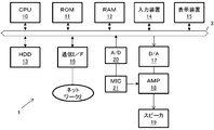
- FIG. 1 shows a configuration example of a beat sound output timing generator.
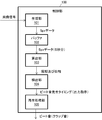
- FIG. 2 shows a configuration example of the control unit.
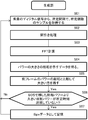
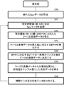
- FIG. 3 is a flowchart showing a processing example of the generation unit.
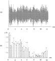
- FIG. 4A shows an example of a digital signal (also referred to as a music signal) for 12 seconds of music input to the generation unit
- FIG. 4B shows an example of Spx data generated from the music signal of FIG. 4A.
- FIG. 5 is a flowchart showing a processing example of the calculation unit.
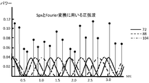
- FIG. 6 is a diagram showing an example of a Spx data and a BPM sine wave used for the Fourier transform.
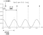
- FIG. 7 illustrates the relationship between the cosine wave indicating BPM and the beat generation timing.
- FIG. 1 shows a configuration example of a beat sound output timing generator.
- FIG. 2 shows a configuration example of the control unit.
- FIG. 3 is a flowchart showing a processing example of the generation unit.
- FIG. 4A shows an example
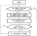
- FIG. 8 is a flowchart showing an example of the beat generation timing detection process by the detection unit 104.
- FIG. 9A is a diagram showing beat positions (beat sound generation timings) detected from music signals by vertical lines.
- FIG. 9B shows the passage of time of the BPM value corresponding to the example shown in FIG. 9A.
- FIG. 10 shows spectral intensity data at a certain moment of music.
- FIG. 11 is a flowchart showing a processing example showing the first method of setting the BPM range.
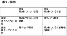
- FIG. 12 is a table illustrating the state of the buttons.
- FIG. 13 is a flowchart showing a processing example showing a second method of setting the BPM range.
- FIG. 14 is a flowchart showing a processing example showing a third method of setting the BPM range.
- FIG. 15 is a flowchart showing a processing example showing a third method of setting a BPM range.
- FIG. 16 shows the beats detected when the second and third methods are carried out with respect to the signal
- the beat is diverse. Diversity means that "musically good beats" are not always the same. Usually, a piece of music has some intrinsic beats, even though the tempo is musically constant.
- a "good beat” may be a beat that is carved to the quarter note on the score. Alternatively, it may be a beat that is carved in time with two beats and three consecutive beats.
- the beat detection (beat sound generation timing generation) algorithm in the prior art often detects these beats in a timely manner and outputs a sound (hand clap sound, etc.) that matches the beat. That is, in a certain time interval, the sound is output according to the quarter note, and in another time interval, the sound is output according to the two beats and triplets. When the beat is expressed as a BMP value, these appear as discontinuous values for each time interval.
- FIG. 9A is a diagram showing the beat position (beat sound generation timing) detected from the signal of the music by a vertical line.
- the cycle of the generation timing of the beat sound is intermittently changed in the middle of the progress of the music.
- FIG. 9B shows the passage of time of the BPM value corresponding to the example shown in FIG. 9A.
- Such a phenomenon that the cycle of the generation timing of the beat sound changes intermittently does not occur because the progress of the music changes at each moment. That is, in a situation where two beats (for example, a quarter note and a double beat triplet) always coexist in a musical piece, the algorithm selects one beat at one moment and the other beat at another moment. It happens from choosing. However, it cannot be determined that one of the beats is correct and the other is incorrect due to the variety of beats.
- the spectral intensity data considered when selecting multiple endogenous beats has several peaks, each of which represents the presence of an intrinsic beat, as shown in FIG. ..
- the largest peak of a plurality of peaks is selected as the beat at each moment. Therefore, as a result, the BPM changes intermittently.
- beat sound generation timing generation device (beat detection device) according to the embodiment is made to solve the above-mentioned problem that an unstable beat sound generation timing is generated.
- the beat sound generation timing generator has the following configuration.
- a generation unit that generates a plurality of intensity data in a predetermined time interval, which is a plurality of intensity data indicating the timing in which each of the input music data controls the beat of the music and the power at the timing.
- a calculation unit that calculates the beat period and phase of a musical piece using a plurality of intensity data for each time interval.
- a detection unit that detects the generation timing of a beat sound based on the cycle and phase of the beat of a musical piece.
- a control unit that sets one of a wide range and a range narrower than the wide range as a range of BPM (Beats Per Minute) used for calculating the beat cycle and phase for each time interval.
- BPM Beats Per Minute
- the narrow range of BPM is a predetermined numerical range centered on the BPM value used for calculating the beat period and phase in the current time interval.
- the period and phase of the beat can be calculated in the range of the BPM centered on the BPM value in the current time interval, and the desired beat can be stably detected.
- the following configuration may be adopted in the beat sound generation timing generator. That is, the calculation unit calculates the beat period and phase for each time interval using the narrow range while the setting for selecting the narrow range is maintained. By doing so, the range of BPM can be made to follow according to the change in the beat of the music.
- the following configuration may be adopted in the beat sound generation timing generator. That is, the control unit sets the BPM range to a wide range while the button for switching the BPM range is held down, and changes the BPM range to a narrow range when the button long press is released. .. In this way, it is possible to switch between a wide range and a narrow range using one button.
- the calculation unit determines the BPM for a plurality of intensity data based on the timing indicated by the plurality of intensity data, calculates one cycle of the BPM as the beat cycle, and generates the beat sound in the sine wave indicating the BPM.
- the relative position of is calculated as the phase of the beat.
- the detection unit obtains a count value indicating the beat cycle and the phase of the beat, measures the count value using a counter that increments the sampling rate for each sample, and determines the timing at which the counter value reaches the count value. Detected as the timing of beat sound generation.
- the following configuration may be adopted in the beat sound generation timing generator. That is, the calculation unit calculates one cycle of BPM when the value of the Fourier transform data obtained by the Fourier transform performed on each of the plurality of intensity data and each of the plurality of BPMs becomes the maximum as the beat cycle.
- the beat sound generation timing generation device the beat sound generation timing generation method, and the program according to the embodiment will be described with reference to the drawings.
- the configuration of the embodiment is an example. It is not limited to the configuration of the embodiment.
- FIG. 1 shows a configuration example of a beat sound generation timing generator.
- the beat sound generation timing generation device may be configured as a single device, or may be incorporated in a karaoke machine or an electronic musical instrument.
- the beat sound generation timing generation device 1 inputs a CPU 10, a ROM (ReadOnlyMemory) 11, a RAM (RandomAccessMemory) 12, a hard disk drive (HDD) 13, and a hard disk drive (HDD) 13 connected to the bus 3.
- a device 14, a display device 15, and a communication interface (communication I / F) 16 are included.
- the beat sound generation timing generation device 1 further includes a digital-to-analog converter (D / A) 17 and an analog-to-digital converter (A / D) 20 connected to the bus 3.
- An amplifier (AMP) 18 is connected to the D / A17, and a speaker 19 is connected to the AMP 18.
- a microphone (MIC) 21 is connected to the A / D20.
- the ROM 11 stores various programs executed by the CPU 10 and data used when executing the programs.
- the RAM 12 is used as a program expansion area, a CPU 10 work area, a data storage area, and the like.
- the HDD 13 stores a program, data used when executing the program, music data, and the like.
- the music data is sound data having a predetermined audio file format such as MP3 or WAVE format.
- the format of the audio file may be other than MP3 or WAVE format.
- the ROM 11 and the RAM 12 are examples of the main storage device, and the HDD 13 is an example of the auxiliary storage device.
- the main storage device and the auxiliary storage device are examples of a storage device or a storage medium.
- the input device 14 is a key, a button, a touch panel, a knob, a switch, etc., and is used for inputting information (including instructions and commands) or setting parameters related to musical sound generation and reproduction.
- the display device 15 is used for displaying information.
- the communication I / F 16 is connected to the network 2 and controls the processing related to the communication.
- the CPU 10 can download desired music data (music signal) from the network 2 and store it in the HDD 13, for example, in response to an instruction input from the input device 14.
- the CPU 10 performs various processes by executing the program.
- the processing includes processing related to music playback, processing to generate the beat sound generation timing of the music, and beat sound (for example, clap sound, particularly hand clap sound) according to the beat sound generation timing.
- beat sound for example, clap sound, particularly hand clap sound
- Etc. Includes processing to output.
- the CPU 10 when the music data is reproduced, the CPU 10 generates digital data (digital signal) representing the sound of the music from the music data read from the HDD 13 to the RAM 12 by executing the program, and supplies the digital data (digital signal) to the D / A17.
- the D / A17 converts digital data representing sound into an analog signal by digital-to-analog conversion, and outputs the digital data to the AMP 18.
- the analog signal whose amplitude is adjusted by the AMP 18 is output from the speaker 19.
- the MIC 21 collects, for example, a singing sound accompanied by the sound of a musical piece output from the speaker 19.
- the analog audio signal collected by the MIC 21 is amplified in amplitude by the AMP 18 and amplified by the speaker 19.
- the singing sound may be mixed with the music sound or may be output from separate speakers.
- the MIC 21 may also collect sound from a performance using a musical instrument (so-called live performance) or a reproduced sound of a musical piece from an external device to expand the sound (output from the speaker 19) or record the sound.
- a performance sound signal collected by the MIC 21 is converted into a digital signal by the A / D 20 and passed to the CPU 10.
- the CPU 10 converts the signal of the performance sound into a format according to the format of the audio file, generates an audio file, and stores it in the HDD 13.
- the beat sound generation timing may be generated for the sound signal of the music collected by the MIC 21.
- the beat sound generation timing generation device 1 may include a drive device (not shown) for a disc-type recording medium such as a compact disc (CD).
- a digital signal representing the sound of the music read from the disk-type recording medium using the drive device may be supplied to the D / A17, and the music sound may be reproduced.
- the beat sound generation timing may be generated for the sound signal of the music read from the disc type recording medium.
- FIG. 2 shows a configuration example of the control unit 100.
- the CPU 10 has a time sparse data (denoted as "Spx data”: corresponding to intensity data) generation unit 101, a buffer 102, a period data and phase data calculation unit 103, and a beat, as shown in FIG. It operates as a control unit 100 including a detection unit 104 of the generation timing of the above, a beat sound reproduction processing unit 105, and the like.
- the buffer 102 is provided, for example, in a predetermined storage area of the RAM 12 or the HDD 13.
- the Spx data generation unit 101 generates and outputs Spx data using digital data representing the sound of a musical piece.
- the buffer 102 stores Spx data (corresponding to a plurality of intensity data) for at least a predetermined time. In the present embodiment, 6 seconds is exemplified as the length of the predetermined time (time interval), but the predetermined time may be longer or shorter than 6 seconds.
- the calculation unit 103 calculates beat cycle data and phase data using a set of Spx data for a predetermined time stored in the buffer 102.
- the generation timing detection unit 104 detects the generation timing of the beat sound using the periodic data and the phase data.
- the reproduction processing unit 105 performs reproduction processing of the beat sound according to the generation timing.
- a digital signal representing the sound of music data (data sent to the D / A 17 for audio output) related to reproduction is input to the generation unit 101.
- the digital signal (music signal) representing the sound may be one obtained by reproduction processing of music data stored in the HDD 13, or one obtained by A / D conversion of the voice signal collected by the MIC 20.
- the digital data representing the sound is stored in the RAM 12 and used for the processing of the generation unit 101.
- Digital data representing sound is a set of sample data (usually a voltage value of an analog signal) collected from an analog signal according to a predetermined sampling rate.
- the sampling rate is assumed to be 44100 Hz.
- the sampling rate can be appropriately changed as long as the desired FFT resolution can be obtained.
- FIG. 3 is a flowchart showing a processing example of the generation unit 101.
- Digital data digital signal representing the sound of a musical piece, which is sent to the D / A17 for musical sound output (reproduction)
- the generation unit 101 acquires a predetermined number of samples (referred to as “frames”) from the input digital data (S01).
- the predetermined number is 1024 in this embodiment, but it may be larger or smaller than this.
- Samples are obtained at predetermined intervals.
- the predetermined interval is, for example, 5 ms, but may be larger or smaller than this.
- the generation unit 101 performs a thinning process. That is, the generation unit 101 performs 1/4 thinning out on 1024 samples to obtain 256 samples. The thinning may be other than 1/4 thinning.
- the generation unit 101 performs a fast Fourier transform (FFT) on 256 samples, and obtains the magnitude of the power (spectral intensity) in frame units from the result of FFT (power for each frequency bandwidth).
- FFT fast Fourier transform
- the indicated data (referred to as power data) is obtained (S04). Since power is expressed by the square of amplitude, the concept of "power" includes amplitude.
- the power data is, for example, the total power obtained by performing an FFT on 256 samples.
- the power of the corresponding bandwidth in the previous frame is subtracted from the power of each frequency bandwidth of this frame, and if the value is positive (power is increasing), the value of that power is summed up. You can leave it for calculation and ignore values that are not (the subtracted value is negative (power is reduced)). This is because there is a high possibility that the beat is where the increase in power is large.
- the value used to calculate the sum is the sum of the powers of the current frame, but the power of the previous frame is subtracted from the power of the current frame.
- the value may be the sum of the powers of positive values or the difference obtained by subtracting the power of the previous frame from the power of the current frame.
- the above-mentioned difference calculation may be performed only for frequencies lower than a predetermined frequency. Frequencies above a predetermined frequency may be cut using a low-pass filter.
- the power data is stored in the RAM 12 and the HDD 13 in frame units. Each time the power data for each frame is created, the generation unit 101 compares the magnitude of the total power (peak value) and leaves the larger one, and discards the smaller one (S05). The generation unit 101 determines whether or not a total sum larger than the total left in S05 has appeared for a predetermined time (S06).
- the predetermined time is, for example, 100 ms, but it may be larger or smaller than 100 ms.
- the generation unit 101 extracts the data indicating the sum of the powers (that is, the maximum peak in the time interval of the predetermined time) as Spx data.
- the Spx data is data obtained by extracting the peak value of digital data indicating a musical tone at intervals of 100 ms, and is information indicating the timing that controls the beat of the music (timing information) and data indicating the power at that timing. be.
- a plurality of Spx data are stored in the buffer 102.
- the generation unit 101 repeats the processes from S01 to S06.
- FIG. 4A is a digital signal of a musical piece for 12 seconds input to the generation unit 101
- FIG. 4B shows an example of Spx data generated from the digital signal of the musical piece shown in FIG. 4A.
- the horizontal axis of the graph shown in FIG. 4B is time, and the vertical axis is power.
- the vertical line with a black circle at the top indicates the individual Spx data obtained from the digital signal of the music shown in FIG. 4A, and the position on the horizontal axis (time axis) indicates the timing of the vertical line. Length indicates power.
- Spx data is generated at intervals of 100 ms, about 10 pieces are generated per second.
- FIG. 5 is a flowchart showing a processing example of the calculation unit 103.
- new Spx data generated by the generation unit 101 arrives at the buffer 102 and is accumulated.
- Spx data (corresponding to a plurality of intensity data) for a predetermined time is acquired from the buffer 102.
- the predetermined time is, for example, 6 seconds, but may be longer or shorter than 6 seconds as long as the beat period and phase can be obtained.
- Subsequent processes of S12 to S16 are processes performed using the Spx data for 6 seconds acquired in S11.
- BPM frequencies BPM frequencies
- f ⁇ 86,90
- FIG. 6 is a diagram showing an example of a sine wave having a BPM frequency used for Spx data and Fourier transform.
- a sine wave of BPM72 (indicated by a solid line), a sine wave of BPM88 (indicated by a broken line), and a sine wave of BPM104 (indicated by a chain double-dashed line) are exemplified.
- the value of the Fourier transform data c (i) is obtained by the following equation 1.
- the BPM value and the number thereof can be changed as appropriate.
- t (k) in Equation 1 is the time position in the past 6 seconds in which the Spx data exists, and the unit is seconds.
- x (t (k)) indicates the value (the magnitude of the peak value) of the Spx data at that moment.
- f (i) is the BPM frequency, for example BPM 120 is 2.0 Hz.
- phase value ⁇ By calculating the phase value ⁇ , it is possible to know the relative position of the beat generation timing with respect to the sine wave of the BPM, that is, how much the beat generation timing is delayed with respect to one cycle of the BPM.
- FIG. 7 illustrates the relationship between the cosine wave indicating BPM (the real part of EXP (2 ⁇ jft)) and the beat generation timing.
- the number of Spx data is 4, and the BPM thereof is 72.
- Each of the Spx data shown in FIG. 7 is a value (phase) of c (i) obtained by using Equation 2, and indicates a beat generation timing.
- the intervals between the Spx data form the beat generation timing.
- the timing delayed by ⁇ / 2 from the cosine wave having the BPM frequency obtained by the calculation of the phase value ⁇ is the beat generation timing.
- the calculation unit 103 uses the number of samples in one cycle of BPM as cycle data (S15).
- the calculation unit 103 outputs the periodic data and the phase data (S16).
- the calculation unit 103 repeats the processes of S11 to S16 every time the Spx data for 6 seconds is accumulated. This makes it possible to follow changes in the rhythm of the music.
- FIG. 8 is a flowchart showing an example of the beat generation timing detection process by the detection unit 104.
- the detection unit 104 determines whether the new periodic data and the phase data are provided by the calculation unit 103. If new periodic data and phase data are provided, processing proceeds to S22, otherwise processing proceeds to S23.
- the detection unit 104 adopts the new periodic data and the phase data for detecting the beat generation timing, and discards the old periodic data and the phase data.
- the sample of the frame forming the Spx data is in a state where a delay of 100 ms is given. Time adjustment (phase adjustment) is performed so that After that, the process proceeds to S23.
- the counter is set using the number of samples of periodic data and the number of samples of phase data.
- the detection unit 104 has a counter that counts up (increments) for each sample of the sampling rate (interval of voltage check of the analog signal according to the sampling rate), and counts the count value of the counter for each sample. Increment. As a result, it waits for the count value to change from zero to a predetermined value (a value indicating the sum of the number of samples of phase data (count value) and the number of samples of periodic data (count value)) (S24).
- the detection unit 104 detects the generation timing of the beat sound based on the prediction and outputs the output instruction of the beat sound (S25).
- the reproduction processing unit 105 sends digital data of a beat sound (for example, a hand clap sound) stored in advance in the ROM 11 or the HDD 13 to the D / A 17 in response to an output instruction.
- the digital data is converted into an analog signal by the D / A 17, and after being amplitude-amplified by the AMP 18, it is output from the speaker 19.
- the hand clap sound is output over the music being played or played.
- ⁇ BPM range setting> For a predetermined number (20 pieces) of BPM selected from a predetermined BPM range (86 to 168), the BPM having the maximum absolute value of the Fourier transform value is determined as the BPM of the beat sound generation timing ( Steps S13 and S14 of FIG. 5).
- the range of BPM can be changed into two stages of "wide range” and "narrow range” by operating the input device 14.
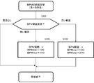
- FIG. 11 is a flowchart showing a processing example showing the first method of setting the BPM range. The flow of FIG. 11 is performed by the CPU 10 executing a program. In step S101, the CPU 10 determines whether or not an instruction for changing the BPM range has been input by operating the input device 14.
- step S101 If it is determined in step S101 that an instruction to change the BPM range to a wide range is input (a wide range is specified), the CPU 10 sets the BPM range to a wide range (step S102). .. As an example of a wide range, the CPU 10 sets the minimum value of BPM to 100 and the maximum value of BPM to 240.
- the CPU 10 sets the BPM range to a narrow range (step S103). ..
- the CPU 10 sets the minimum value of BPM to 120 and the maximum value of BPM to 160. If it is determined that there is no change, the CPU 10 does not perform any particular processing, and the current BPM range setting is maintained.
- the minimum and maximum values of BPM in each of a wide range and a narrow range are examples, and appropriate values can be set. This also applies to the second and third methods described later.
- FIG. 11 is performed, for example, by operating one button included in the input device 14. That is, the CPU 10 periodically monitors the state of the button.
- FIG. 12 is a table showing the states of the buttons. If the state immediately before the button is not pressed and the current state is not pressed, the CPU 10 does not perform the process of changing the BPM range as "no change". On the other hand, when the button is pressed for a long time, that is, when the pressed state continues at the detection timing of two or more states, the CPU 10 determines that the operation is the input of the change command. A process of changing the range of BPM to a wide range is performed (S101). When the button is released from the long-pressed state, the CPU 10 determines that the operation is an input of a change command, and performs a process of changing the BPM range to a narrow range.
- the CPU 10 may change the BPM range each time the button is pressed. Further, instead of the button, a knob having a range corresponding to two ranges, a wide range and a narrow range, may be used.
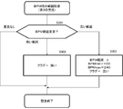
- FIG. 13 is a flowchart showing a processing example showing a second method of setting the BPM range. The flow of FIG. 13 is performed by the CPU 10 executing a program. In step S201, the CPU 10 determines whether or not an instruction for changing the BPM range has been input by operating the input device 14.
- step S201 When it is determined in step S201 that an instruction to change the BPM range to a wide range is input (a wide range is specified), the CPU 10 sets the BPM range to a wide range as in step S102. Set (step S202).
- the CPU 10 acquires the current BPM value m and sets the BPM range.
- M is set in a range separated from the value by a predetermined percentage.
- the predetermined percentage is, for example, 2 to 15%, more preferably 5 to 10%.
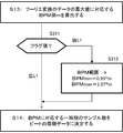
- FIGS. 14 and 15 are flowcharts showing a processing example showing a third method of setting a BPM range.
- the flow of FIGS. 14 and 15 is performed by the CPU 10 executing a program.
- step S301 the CPU 10 determines whether or not an instruction for changing the BPM range has been input by operating the input device 14.
- step S301 When it is determined in step S301 that an instruction to change the BPM range to a wide range is input (a wide range is specified), the CPU 10 sets the BPM range to a wide range as in step S102. Set. Further, the value of the flag indicating whether the range is wide or narrow is set to "wide" (value: 0 or 1) (step S302). On the other hand, when it is determined that an instruction to change the BPM range to a narrow range is input (a narrow range is specified), the CPU 10 sets the value of the flag to "narrow" (value: 1 or 0). ) (Step S303).
- step S13 of FIG. 5 the BPM value m corresponding to the maximum absolute value of the data of the Fourier transform is calculated.
- the CPU 10 confirms the flag value in step S311 and the flag value is "narrow"
- the CPU 10 sets the BPM range to a range of 7% above and below the BPM value m, as in step S202. Narrow.
- the process proceeds to step S14.
- the process of step S14 is executed in a wide BPM range.
- the range of BPM is usually set to "a wide range”. Then, when the generation of the generation timing of the beat sound (beat detection) is in progress and more stable beat detection is desired, the beat is detected by the operation of the input device 14 (operator). Switch the BPM range for "narrow range”.
- the intrinsic beat of a song is 2/3 or 4/3, which is an integer ratio. From this, the "narrow range" is limited to the range of BPM which is several percent to several tens of percent narrower than the wide range. As a result, one of the two beats is out of the range of BPM for detecting the maximum BPM, so that the generation timing of the beat sound based on the corresponding beat is not generated. This makes it possible to constantly generate a substantially constant beat sound generation timing.
- the current BPM value is acquired at the moment of operation of the input device 14 (operator), for example, when the button is released from the long press of the button (selection of "wide range”). Then, a few percent above and below the acquired BPM value is set as the “narrow range", and the BPM range for detecting the beat is switched to the "narrow range”.
- the user of the beat sound generation timing generation device 1 selects and operates the moment when the beat desired by the user is detected (such as releasing the long press of the button).
- a narrow range of BPM including the BPM of the desired beat can be set.
- the generation timing of the beat sound for the beat desired by the user can be generated, and the generation timing of the beat sound that is consistently substantially constant without crossing can be generated.
- FIG. 16 shows the beat (beat sound generation timing) detected when the second and third methods are performed with respect to the signal of the music shown in FIG. 9A, and is represented by a vertical line, and the change in BPM. It can be seen that the generation timing of the beat sound is stably generated (detected) even if the sound is generated as shown in 9B.
- the process performed by the control unit 100 may be performed by a plurality of CPUs (processors) or by a CPU having a multi-core configuration. Further, the processing performed by the control unit 100 is executed by a processor other than the CPU 10 (DSP, GPU, etc.), an integrated circuit other than the processor (ASIC, FPGA, etc.), or a combination of the processor and the integrated circuit (MPU, SoC, etc.). You may.
Landscapes
- Physics & Mathematics (AREA)
- Engineering & Computer Science (AREA)
- Acoustics & Sound (AREA)
- Multimedia (AREA)
- Auxiliary Devices For Music (AREA)
- Electrophonic Musical Instruments (AREA)
Abstract
情報処理装置は、入力された楽曲のデータから、夫々が楽曲のビートを司るタイミングと、そのタイミングにおけるパワーを示す複数の強度データであって、所定の時間区間における複数の強度データを生成する処理と、時間区間毎に、複数の強度データを用いて楽曲のビートの周期及び位相を算出する処理と、算出した楽曲のビートの周期及び位相に基づいて、ビート音の発生タイミングを検出する処理と、時間区間毎のビートの周期及び位相の算出に用いるBPMの範囲として、広い範囲と、前記広い範囲より狭い範囲との一方を設定する処理とを行う。
Description
本開示は、ビート音発生タイミング生成装置、ビート音発生タイミング生成方法、及びプログラムに関する。
従来、楽曲の信号から、ビート音の発生タイミングを生成する技術がある(例えば、特許文献1参照)。
楽曲には、音楽的にテンポがほぼ一定であるにも関わらず、幾つかの内在的なビートが同時に存在している場合が少なくない。例えば、楽曲を楽譜上の四分音符に合わせて刻むこともできれば、二拍三連に合わせて刻むこともできる場合がある。従来技術では、楽曲の進行において、ある時間区間では四分音符に合わせたビートを検出し、ある時間区間では二拍三連に合わせたビートを検出するといった、不安定なビート音の発生タイミングを生成することがあった。
本開示は、ビート音の発生タイミングを安定させることのできるビート音発生タイミング生成装置、ビート音発生タイミング生成方法、及びプログラムを提供することを目的とする。
本開示の一側面は、入力された楽曲のデータから、夫々が前記楽曲のビートを司るタイミングと、前記タイミングにおけるパワーとを示す複数の強度データであって、所定の時間区間における複数の強度データを生成する生成部と、
前記時間区間毎に、前記複数の強度データを用いて前記楽曲のビートの周期及び位相を算出する算出部と、
前記楽曲のビートの周期及び位相に基づいて、ビート音の発生タイミングを検出する検出部と、
前記時間区間毎の前記ビートの周期及び位相の算出に用いるBPM(Beats Per Minute)の範囲として、広い範囲と、前記広い範囲より狭い範囲との一方を設定する制御部と
を含むビート音発生タイミング生成装置である。
前記時間区間毎に、前記複数の強度データを用いて前記楽曲のビートの周期及び位相を算出する算出部と、
前記楽曲のビートの周期及び位相に基づいて、ビート音の発生タイミングを検出する検出部と、
前記時間区間毎の前記ビートの周期及び位相の算出に用いるBPM(Beats Per Minute)の範囲として、広い範囲と、前記広い範囲より狭い範囲との一方を設定する制御部と
を含むビート音発生タイミング生成装置である。
本開示の一態様は、上記したビート音発生タイミング生成装置と同様の特徴を有する、ビート音発生タイミング生成方法、プログラム、プログラムを記録した記録媒体などであってもよい。
演奏又は再生される楽曲に合わせて対してビートを刻む場合、そのビートには多様性がある。多様性とは、「音楽的に良好なビートの刻み方」は、必ずしも一通りではないということである。通常、楽曲には、音楽的にテンポがほぼ一定であるにも関わらず、いくつかの内在的なビートが存在する。「良好なビート」は、楽譜上の四分音符に合わせて刻まれるビートであるかも知れない。或いは、二拍三連に合わせて刻まれるビートであるかもしれない。
従来技術におけるビート検出(ビート音の発生タイミング生成)のアルゴリズムは、しばしばこれらのビートを時間的に混在して検出し、ビートに合わせた音(ハンドクラップ音など)を出力する。すなわち、或る時間区間では四分音符に合わせて音が出力され、別の時間区間では二拍三連に合わせて音が出力される。ビートをBMP値で表したとき、これらは時間区間毎の不連続な値として現れる。
図9Aは、楽曲の信号から検出したビート位置(ビート音の発生タイミング)を縦線で示した図である。図9Aに示す例では、楽曲の進行の途中でビート音の発生タイミングの周期が断続的に変化している。図9Bは、図9Aに示した例に該当するBPM値の時間経過を示す。このような、ビート音の発生タイミングの周期が断続的に変化する現象は、各瞬間に楽曲の進行が変化しているために起こる訳ではない。すなわち、楽曲において常に二つのビート(例えば、四分音符と二拍三連)が内在的に共存している状態において、アルゴリズムがある瞬間は一方のビートを選択し、またある瞬間は他方のビートを選択してしまうことから起こる。もっとも、ビートの多様性からいずれか一方のビートが正しく、他方が誤っているとは判断できない。
内在的に複数存在するビートを選択する際に考慮されるスペクトル強度データは、図10に示すように、幾つかのピークを有し、ピークの夫々は、内在的なビートの存在をあらわしている。従来技術では、複数のピーク中の最大のピークを各瞬間のビートとして選択する。このため、結果的に断続的にBPMが変化することになる。
このような、断続的なBPMの変化に従ったビート音の発生タイミングに従って音を発することは、好適でない場合がある。例えば、或る瞬間で四分音符に従ったビートを検出している場合には、恒常的に四分音符でビートを検出し続けるのが好ましい。実施形態に係るビート音発生タイミング生成装置(ビート検出装置)は、上記のような、不安定なビート音の発生タイミングが生成される問題を解決するためになされたものである。
実施形態に係るビート音発生タイミング生成装置は、以下の構成を有する。
(1)入力された楽曲のデータから、夫々が楽曲のビートを司るタイミングと、タイミングにおけるパワーとを示す複数の強度データであって、所定の時間区間における複数の強度データを生成する生成部。
(2)時間区間毎に、複数の強度データを用いて楽曲のビートの周期及び位相を算出する算出部。
(3)楽曲のビートの周期及び位相に基づいて、ビート音の発生タイミングを検出する検出部。
(4)時間区間毎のビートの周期及び位相の算出に用いるBPM(Beats Per Minute)の範囲として、広い範囲と、前記広い範囲より狭い範囲との一方を設定する制御部。
(1)入力された楽曲のデータから、夫々が楽曲のビートを司るタイミングと、タイミングにおけるパワーとを示す複数の強度データであって、所定の時間区間における複数の強度データを生成する生成部。
(2)時間区間毎に、複数の強度データを用いて楽曲のビートの周期及び位相を算出する算出部。
(3)楽曲のビートの周期及び位相に基づいて、ビート音の発生タイミングを検出する検出部。
(4)時間区間毎のビートの周期及び位相の算出に用いるBPM(Beats Per Minute)の範囲として、広い範囲と、前記広い範囲より狭い範囲との一方を設定する制御部。
ビート音発生タイミング生成装置において、以下の構成を採用してもよい。すなわち、 狭い範囲のBPMの範囲が、現在の時間区間においてビートの周期及び位相の算出に用いられるBPM値を中心とした所定の数値範囲である。このようにすれば、現在の時間区間におけるBPM値を中心としたBPMの範囲で、ビートの周期及び位相を算出することができ、所望のビートを安定的に検出可能となる。
ビート音発生タイミング生成装置において、以下の構成を採用してもよい。すなわち、算出部は、狭い範囲を選択する設定が維持されている間、時間区間毎のビートの周期及び位相の算出を、狭い範囲を用いて行う。このようにすれば、楽曲のビートの変化に応じてBPMの範囲を追従させることができる。
ビート音発生タイミング生成装置において、以下の構成を採用してもよい。すなわち、 制御部は、BPMの範囲を切り替えるボタンが長押しされている間、BPMの範囲を広い範囲に設定し、ボタンの長押しが解除された場合に、BPMの範囲を狭い範囲に変更する。このようにすれば、一つのボタンを用いて広い範囲と狭い範囲との切替を行うことができる。
ビート音発生タイミング生成装置において、以下の構成を採用してもよい。すなわち、 算出部は、複数の強度データが示すタイミングに基づいて複数の強度データについてのBPMを定め、BPMの一周期をビートの周期として算出するともに、BPMを示す正弦波におけるビート音の発生タイミングの相対位置をビートの位相として算出する。検出部は、ビートの周期及びビートの位相を示すカウント値を求め、サンプリングレートの1サンプル毎にインクリメントを行うカウンタを用いてカウント値の計時を行い、カウンタの値がカウント値に達したタイミングをビート音の発生タイミングとして検出する。
ビート音発生タイミング生成装置において、以下の構成を採用してもよい。すなわち、算出部は、複数の強度データの夫々と複数個のBPMの夫々について行うフーリエ変換によって得られたフーリエ変換データの値が最大となるときのBPMの一周期をビートの周期として算出する。
〔実施形態〕
以下、図面を参照して、実施形態に係るビート音発生タイミング生成装置、ビート音発生タイミング生成方法、及びプログラムについて説明する。実施形態の構成は例示である。実施形態の構成に限定されない。
以下、図面を参照して、実施形態に係るビート音発生タイミング生成装置、ビート音発生タイミング生成方法、及びプログラムについて説明する。実施形態の構成は例示である。実施形態の構成に限定されない。
図1は、ビート音発生タイミング生成装置の構成例を示す。ビート音発生タイミング生成装置は、単独の装置として構成される場合もあれば、カラオケ機器、或いは電子楽器に組み込まれる場合もある。図1において、ビート音発生タイミング生成装置1は、バス3に接続された、CPU10と、ROM(Read Only Memory)11と、RAM(Random Access Memory)12と、ハードディスクドライブ(HDD)13と、入力装置14と、表示装置15と、通信インタフェース(通信I/F)16とを含む。ビート音発生タイミング生成装置1は、さらに、バス3に接続された、ディジタルアナログ変換器(D/A)17と、アナログディジタル変換器(A/D)20とを含む。D/A17にはアンプ(AMP)18が接続され、AMP18にはスピーカ19が接続されている。A/D20には、マイクロフォン(MIC)21が接続されている。
ROM11は、CPU10によって実行される様々なプログラムやプログラムの実行に際して使用されるデータを記憶している。RAM12は、プログラムの展開領域、CPU10の作業領域、データの記憶領域などとして使用される。HDD13は、プログラムやプログラムの実行に際して使用されるデータ、楽曲データなどを記憶する。楽曲データは、例えばMP3やWAVE形式などの所定の音声ファイルのフォーマットを有する音データである。音声ファイルのフォーマット形式は、MP3やWAVE形式以外でもよい。ROM11及びRAM12は、主記憶装置の一例であり、HDD13は補助記憶装置の一例である。主記憶装置及び補助記憶装置は、記憶装置又は記憶媒体の一例である。
入力装置14は、キー、ボタン、タッチパネル、つまみ、スイッチなどであり、情報(指示や命令を含む)の入力、或いは楽音の生成や再生に関するパラメータの設定に使用される。表示装置15は、情報の表示に使用される。通信I/F16は、ネットワーク2に接続されており、通信に係る処理を司る。CPU10は、例えば入力装置14から入力された指示に応じて、ネットワーク2から所望の楽曲データ(楽曲信号)をダウンロードし、HDD13に記憶することができる。
CPU10は、プログラムの実行によって、様々な処理を行う。処理は、上記した楽曲ダウンロードに係る処理の他、楽曲の再生に係る処理、楽曲のビート音発生タイミングを生成する処理、ビート音発生タイミングに合わせてビート音(例えば、クラップ音、特にハンドクラップ音など)を出力する処理などを含む。
例えば、CPU10は、楽曲データを再生する場合、プログラムの実行によって、HDD13からRAM12に読み出した楽曲データから楽曲の音を表すディジタルデータ(ディジタル信号)を生成し、D/A17に供給する。D/A17は、音を表すディジタルデータをディジタルアナログ変換によってアナログ信号に変換し、AMP18に出力する。AMP18によって振幅が調整されたアナログ信号はスピーカ19から出力される。
MIC21は、例えば、スピーカ19から出力される楽曲の音を伴奏(カラオケ)とする歌唱音などを集音する。MIC21で集音されたアナログの音声信号は、AMP18で振幅を増幅され、スピーカ19から増幅される。このとき、歌唱音は楽曲音とミキシングされても、それぞれ別個のスピーカから出力されてもよい。
また、MIC21は、楽器を用いた演奏(いわゆる生演奏)による音声や外部機器からの楽曲の再生音声を集音して音を拡大(スピーカ19から出力)したり、録音したりする場合にも使用される。例えば、MIC21で集音された演奏音の信号は、A/D20によってディジタル信号に変換され、CPU10に渡される。CPU10は、演奏音の信号を音声ファイルのフォーマットに従った形式に変換して音声ファイルを生成し、HDD13に記憶する。MIC21で集音される楽曲の音信号について、ビート音発生タイミングの生成処理が行われてもよい。
なお、ビート音発生タイミング生成装置1がコンパクトディスク(CD)などのディスク型記録媒体のドライブ装置(図示せず)を含んでもよい。この場合、ドライブ装置を用いてディスク型記録媒体から読み出された楽曲の音を表すディジタル信号がD/A17に供給され、楽曲音が再生されてもよい。この場合、ディスク型記録媒体から読み出された楽曲の音信号について、ビート音発生タイミングの生成処理が行われてもよい。
図2は、制御部100の構成例を示す。CPU10は、プログラムの実行によって、図2に示すような、時間スパースデータ(「Spxデータ」と表記:強度データに相当)の生成部101、バッファ102、周期データ及び位相データの算出部103、ビートの発生タイミングの検出部104、及びビート音の再生処理部105などを含んだ制御部100として動作する。バッファ102は、例えば、RAM12やHDD13の所定の記憶領域に設けられる。
Spxデータの生成部101は、楽曲の音を表すディジタルデータを用いて、Spxデータを生成して出力する。バッファ102は、少なくとも所定時間分のSpxデータ(複数の強度データに相当)を蓄積する。本実施形態では、所定時間(時間区間)の長さとして6秒を例示するが、所定時間は6秒より長くても短くてもよい。算出部103は、バッファ102に蓄積された所定時間分のSpxデータの集合を用いて、ビートの周期データ及び位相データを算出する。発生タイミングの検出部104は、周期データ及び位相データを用いてビート音の発生タイミングを検出する。再生処理部105は、発生タイミングに合わせたビート音の再生処理を行う。
以下、制御部100をなす各部における処理の詳細を説明する。
<Spxデータの生成>
生成部101によるSpxデータの生成について説明する。生成部101には、再生に係る楽曲データ(音声出力のためにD/A17に送られたデータ)の音を表すディジタル信号が入力される。音を表すディジタル信号(楽曲信号)は、HDD13に記憶された楽曲データの再生処理によるものでも、MIC20で集音された音声信号のA/D変換によって得られたものでもよい。
<Spxデータの生成>
生成部101によるSpxデータの生成について説明する。生成部101には、再生に係る楽曲データ(音声出力のためにD/A17に送られたデータ)の音を表すディジタル信号が入力される。音を表すディジタル信号(楽曲信号)は、HDD13に記憶された楽曲データの再生処理によるものでも、MIC20で集音された音声信号のA/D変換によって得られたものでもよい。
音を表すディジタルデータは、RAM12に記憶され、生成部101の処理に使用される。音を表すディジタルデータは、アナログ信号から所定のサンプリングレートに従って採取されたサンプル(標本)データ(通常、アナログ信号の電圧値)の集合である。本実施形態では、一例として、サンプリングレートは44100Hzであるとする。但し、サンプリングレートは、所望のFFT解像度が得られる限りにおいて適宜変更可能である。
図3は、生成部101の処理例を示すフローチャートである。生成部101には、楽音出力(再生)のためにD/A17へ送られた、楽曲の音を表すディジタルデータ(ディジタル信号)が入力される。生成部101は、入力されたディジタルデータから、所定個数のサンプル(「フレーム」と呼ぶ)を取得する(S01)。所定個数は、本実施形態では1024であるがこれより多くても少なくてもよい。サンプルの取得は、所定間隔で行われる。所定間隔は、例えば5msであるが、これより多くても少なくてもよい。
S02では、生成部101は、間引き処理を行う。すなわち、生成部101は、1024個のサンプルに対する1/4間引きを行って、256個のサンプルを得る。間引きは1/4間引き以外でもよい。S03では、生成部101は、256個のサンプルに対して高速フーリエ変換(FFT)を施し、FFTの結果(周波数バンド幅毎のパワー)から、フレーム単位でのパワー(スペクトル強度)の大きさを示すデータ(パワーデータという)を得る(S04)。なお、パワーは振幅の2乗で表されることから、「パワー」との概念には振幅も含まれる。
パワーデータは、例えば、256個のサンプルに対するFFTの実施によって得られるパワーの総和である。但し、今回のフレームの各周波数バンド幅のパワーから前回のフレームにおける、対応するバンド幅のパワーを差し引き、その値が正である(パワーが増加している)場合にはそのパワーの値を総和計算のために残し、そうでない(差し引いた値が負である(パワーが減少している))値は無視してもよい。パワーの増加分が大きいところがビートである可能性が高いからである。
また、他のフレームとの比較対象が同じである限りにおいて、総和の算出に用いる値は、今回のフレームのパワーの総和であっても、今回のフレームのパワーから前回のフレームのパワーを引いた値が正の値のパワーの総和であっても、今回のフレームのパワーから前回のフレームのパワーを差し引いた差分であってもよい。また、FFTの実施によって得られるパワースペクトルにおいて、所定の周波数より低い周波数についてのみ、上記した差分の算出が行われてもよい。所定の周波数以上の周波数については、ローパスフィルタを用いてカットしてもよい。
パワーデータは、フレーム単位で、RAM12やHDD13に記憶される。生成部101は、フレーム単位のパワーデータが作成される毎に、パワーの総和(ピーク値)の大きさを比較して大きい方を残し、小さい方は破棄する(S05)。生成部101は、S05で残した総和より大きい総和が所定時間出現していないか否かを判定する(S06)。所定時間は例えば100msであるが、100msより大きくても小さくてもよい。より大きい総和を示すデータが出現していない状態が所定時間続いた場合に、生成部101は、そのパワーの総和を示すデータ(すなわち、所定時間の時間区間における最大のピーク)をSpxデータとして抽出し、バッファ102に記憶(保存)する(S07)。このように、Spxデータは、楽音を示すディジタルデータのピーク値を100ms間隔で抽出したデータであり、楽曲のビートを司るタイミングを示す情報(タイミング情報)と、そのタイミングにおけるパワーとを示すデータである。Spxデータは、バッファ102に複数個蓄積される。生成部101は、S01からS06までの処理を繰り返し行う。
図4Aは、生成部101に入力される12秒分の楽曲のディジタル信号であり、図4Bは、図4Aに示した楽曲のディジタル信号から生成されたSpxデータの例を示す。図4Bに示すグラフの横軸は時間で、縦軸はパワーである。このグラフにおいて、上端に黒丸のついた縦線が、図4Aに示した楽曲のディジタル信号から得られた個々のSpxデータを示し、横軸(時間軸)の位置がタイミングを示し、縦線の長さがパワーを示す。Spxデータは、100ms間隔で生成される場合、1秒間に10個程度生成される。
<周期データ及び位相データの算出>
図5は、算出部103の処理例を示すフローチャートである。S10において、生成部101にて生成された新たなSpxデータがバッファ102に到来し、蓄積される。S11において、バッファ102に蓄積されたSpxデータのうち所定時間分のSpxデータ(複数の強度データに相当)がバッファ102から取得される。所定時間は、例えば6秒間であるが、ビートの周期及び位相を得られる限りにおいて6秒より長くても短くてもよい。以降のS12~S16の処理は、S11で取得した6秒分のSpxデータを用いて行われる処理である。S12では、6秒分のSpxデータについて、所定個数(例えば20個)のBPM(Beats Per Minute:テンポ(リズムの速さ)を示す)に対応したフーリエ変換を施し、ビートの周期(BPMの一周期)とビートの位相(ビート音の発生タイミングとを算出する。
図5は、算出部103の処理例を示すフローチャートである。S10において、生成部101にて生成された新たなSpxデータがバッファ102に到来し、蓄積される。S11において、バッファ102に蓄積されたSpxデータのうち所定時間分のSpxデータ(複数の強度データに相当)がバッファ102から取得される。所定時間は、例えば6秒間であるが、ビートの周期及び位相を得られる限りにおいて6秒より長くても短くてもよい。以降のS12~S16の処理は、S11で取得した6秒分のSpxデータを用いて行われる処理である。S12では、6秒分のSpxデータについて、所定個数(例えば20個)のBPM(Beats Per Minute:テンポ(リズムの速さ)を示す)に対応したフーリエ変換を施し、ビートの周期(BPMの一周期)とビートの位相(ビート音の発生タイミングとを算出する。
具体的に説明すると、6秒分のSpxデータについて所定のBPM範囲における所定個数のBPM、例えばBPM86~168に対応する20個、のBPMに対応する周波数(BPM周波数)f = {86,90,94,…,168}/60 について、Exp(2πjft)(BPM周波数で振動する正弦波、振動数に関係無く振幅は同じ)に対する積和をとる。すなわちフーリエ変換を行う。フーリエ変換の結果をフーリエ変換データc(i) (i=0,1, 2, 3,…,19)とする。
図6は、Spxデータとフーリエ変換に用いるBPM周波数を有する正弦波の例を示す図である。図6の例では、BPM72の正弦波(実線で示す)と、BPM88の正弦波(破線で示す)と、BPM104の正弦波(一点鎖線で示す)とが例示されている。フーリエ変換データc(i)の値は以下の式1により求められる。なお、BPMの値及びその個数は適宜変更することができる。

ここに、式1におけるt(k)は、Spxデータの存在する過去6秒のうちの時間位置であり、単位は秒である。kはそのSpxデータのインデックスであり、k=1,...,Mである(MはSpxデータの個数)。また、x(t(k))は、その瞬間のSpxデータの値(ピーク値の大きさ)を示す。jは虚数単位(j2=-1)である。f(i)はBPM周波数であり、例えばBPM120は2.0Hzである。
算出部103は、c(i)=(c0, 1, c2, c3, ... ,c19)のうち、その絶対値が最大値に対応するBPMをSpxデータ(ビート)のBPMに決定する(S13)。また、その位相値(Phase)φ= Arg(c(i))[rad] を、6秒間分のSpxデータについてのビートタイミングとする。 ビートタイミングは、周期的に到来するビートの発生タイミングに対する相対的な位置を示す。
位相値φは複素数の偏角であり、c=cre+jcim(creは実部でcimは虚部)とした場合に、以下の式2により得られる。

位相値φの算出によって、BPMの正弦波に対するビートの発生タイミングの相対位置、すなわち、BPMの一周期に対してビート発生タイミングがどのくらい遅れているかがわかる。
図7は、BPMを示す余弦波(EXP(2πjft)の実部)と、ビートの発生タイミングとの関係を図示する。図7に示す例では、Spxデータの個数が4であり、そのBPMが72である。図7に示すSpxデータの夫々は、式2を用いて求められるc(i)の値(位相)であり、ビートの発生タイミングを示す。Spxデータ間がビート発生タイミングの間隔をなす。図7に示す例では、位相値φの計算によって得られる、BPM周波数を有する余弦波からπ/2遅れたタイミングがビートの発生タイミングとなる。算出部103は、BPMの一周期のサンプル数を周期データとする(S15)。
例えば、BPMが104であり、サンプリングレートが44100Hzの場合では、周期データ(サンプル数)は、44100[個]/(104/60)=25442[個]となる。また、周期データが25442[個]の場合において、位相値φが0.34[rad]であった場合、位相データ(サンプル数)は、25442[個]×0.34[rad]/2π[rad]=1377[個]となる。そして、算出部103は、周期データ及び位相データを出力する(S16)。なお、算出部103は、6秒分のSpxデータが蓄積されるごとに、S11~S16の処理を繰り返し行う。これにより、楽曲のリズムの変更に追従することができる。
<ビート発生タイミングの検出>
図8は、検出部104によるビート発生タイミングの検出処理の例を示すフローチャートである。S21において、検出部104は、新しい周期データ及び位相データが算出部103から提供されたかを判定する。新しい周期データ及び位相データが提供された場合には、処理がS22に進み、そうでない場合には、処理がS23に進む。
図8は、検出部104によるビート発生タイミングの検出処理の例を示すフローチャートである。S21において、検出部104は、新しい周期データ及び位相データが算出部103から提供されたかを判定する。新しい周期データ及び位相データが提供された場合には、処理がS22に進み、そうでない場合には、処理がS23に進む。
S22では、検出部104は、新しい周期データ及び位相データをビート発生タイミングの検出に採用し、古い周期データ及び位相データは破棄する。このとき、Spxデータの作成時に、Spxデータをなすフレームのサンプルは、100ms遅延が与えられた状態となっているため、ここで、演奏又は再生中の楽曲とリズムと、後述するハンドクラップ音とが一致するように時間調整(位相調整)が行われる。その後、処理がS23に進む。
S23では、周期データのサンプル数及び位相データのサンプル数を用いたカウンタの設定を行う。例えば、検出部104は、サンプリングレートの1サンプル(サンプリングレートに従ったアナログ信号の電圧チェックの間隔)毎にカウントアップ(インクリメント)を行うカウンタを有し、当該カウンタのカウント値を1サンプル毎にインクリメントする。これによってカウント値が零から所定値(位相データのサンプル数(カウント値)及び周期データのサンプル数(カウント値)の和を示す値)以上になるのを待つ(S24)。
カウンタのカウント値が所定値以上になると、検出部104は、予測に基づく、ビート音の発生タイミングを検出し、ビート音の出力指示を出力する(S25)。再生処理部105は、出力指示に応じて、ROM11又はHDD13に予め記憶していたビート音(例えば、ハンドクラップ音)のディジタルデータをD/A17へ送る。ディジタルデータはD/A17でアナログ信号に変換され、AMP18で振幅増幅された後、スピーカ19から出力される。これによって、再生又は演奏中の楽曲に重ねてハンドクラップ音が出力される。
<BPMの範囲設定>
上記した例では、所定のBPMの範囲(86~168)から選ばれた所定個数(20個)BPMに関して、フーリエ変換値の絶対値が最大となるBPMをビート音発生タイミングのBPMに決定する(図5のステップS13及びS14)。実施形態に係るビート音発生タイミング生成装置1では、入力装置14の操作によって、BPMの範囲を「広い範囲」と「狭い範囲」との2段階に変更することができる。
上記した例では、所定のBPMの範囲(86~168)から選ばれた所定個数(20個)BPMに関して、フーリエ変換値の絶対値が最大となるBPMをビート音発生タイミングのBPMに決定する(図5のステップS13及びS14)。実施形態に係るビート音発生タイミング生成装置1では、入力装置14の操作によって、BPMの範囲を「広い範囲」と「狭い範囲」との2段階に変更することができる。
(第1の方法)
図11は、BPMの範囲を設定する第1の方法を示す処理例を示すフローチャートである。図11のフローは、CPU10がプログラムを実行することによって行われる。ステップS101では、CPU10は、入力装置14の操作によって、BPMの範囲を変更する命令が入力されたか否かを判定する。
図11は、BPMの範囲を設定する第1の方法を示す処理例を示すフローチャートである。図11のフローは、CPU10がプログラムを実行することによって行われる。ステップS101では、CPU10は、入力装置14の操作によって、BPMの範囲を変更する命令が入力されたか否かを判定する。
ステップS101において、BPMの範囲を広い範囲に変更する命令が入力された(広い範囲が指定された)と判定される場合には、CPU10は、BPMの範囲を広い範囲に設定する(ステップS102)。広い範囲の一例として、CPU10は、BPMの最小値を100に設定するとともに、BPMの最大値を240に設定する。
これに対し、BPMの範囲を狭い範囲に変更する命令が入力された(狭い範囲が指定された)と判定される場合には、CPU10は、BPMの範囲を狭い範囲に設定する(ステップS103)。狭い範囲の一例として、CPU10は、BPMの最小値を120に設定するとともに、BPMの最大値を160に設定する。なお、変更なしと判定される場合には、CPU10は特に処理を行わず、現在のBPMの範囲の設定が維持される。なお、広い範囲及び狭い範囲の夫々におけるBPMの最小値及び最大値は例示であり、適宜の値を設定可能である。これは、後述する第2及び第3の方法においても同様である。
図11に示す処理は、例えば、入力装置14に含まれる一つのボタンの操作によって行われる。すなわち、CPU10は、周期的に、ボタンの状態を監視する。図12は、ボタンの状態を示す表である。ボタンの直前の状態が押していない状態で、現在の状態も押されていない状態であれば、「変更なし」として、CPU10は、BPMの範囲を変更する処理を行わない。これに対し、ボタンが長押しされた場合、すなわち、2以上の状態の検出タイミングにおいて、押されている状態が継続している場合には、その操作をCPU10は変更命令の入力と判定し、BPMの範囲を広い範囲に変更する処理を行う(S101)。また、長押しの状態からボタンの押圧が解除された場合には、その操作をCPU10は変更命令の入力と判定し、BPMの範囲を狭い範囲に変更する処理を行う。
上記した構成の代わりに、CPU10は、ボタンが押される毎に、BPMの範囲を変更するようにしてもよい。また、ボタンの代わりに、広い範囲及び狭い範囲の二つの範囲に対応するレンジを有するつまみが用いられてもよい。
(第2の方法)
図13は、BPMの範囲を設定する第2の方法を示す処理例を示すフローチャートである。図13のフローは、CPU10がプログラムを実行することによって行われる。ステップS201では、CPU10は、入力装置14の操作によって、BPMの範囲を変更する命令が入力されたか否かを判定する。
図13は、BPMの範囲を設定する第2の方法を示す処理例を示すフローチャートである。図13のフローは、CPU10がプログラムを実行することによって行われる。ステップS201では、CPU10は、入力装置14の操作によって、BPMの範囲を変更する命令が入力されたか否かを判定する。
ステップS201において、BPMの範囲を広い範囲に変更する命令が入力された(広い範囲が指定された)と判定される場合には、CPU10は、ステップS102と同様に、BPMの範囲を広い範囲に設定する(ステップS202)。
これに対し、BPMの範囲を狭い範囲に変更する命令が入力された(狭い範囲が指定された)と判定される場合には、CPU10は、現在のBPM値mを取得し、BPMの範囲を、mの値から所定のパーセンテージだけ離れた範囲に設定する。図12に示す例では、mの値から上下7%離れた値の夫々がBPMの最小値及び最大値に設定されている。所定のパーセンテージは、例えば2~15%であり、さらに好ましくは5~10%である。
(第3の方法)
図14及び15は、BPMの範囲を設定する第3の方法を示す処理例を示すフローチャートである。図14及び15のフローは、CPU10がプログラムを実行することによって行われる。ステップS301では、CPU10は、入力装置14の操作によって、BPMの範囲を変更する命令が入力されたか否かを判定する。
図14及び15は、BPMの範囲を設定する第3の方法を示す処理例を示すフローチャートである。図14及び15のフローは、CPU10がプログラムを実行することによって行われる。ステップS301では、CPU10は、入力装置14の操作によって、BPMの範囲を変更する命令が入力されたか否かを判定する。
ステップS301において、BPMの範囲を広い範囲に変更する命令が入力された(広い範囲が指定された)と判定される場合には、CPU10は、ステップS102と同様に、BPMの範囲を広い範囲に設定する。また、範囲が広いか狭いかを示すフラグの値を「広い」(値:0又は1)に設定する(ステップS302)。これに対し、BPMの範囲を狭い範囲に変更する命令が入力された(狭い範囲が指定された)と判定される場合には、CPU10は、フラグの値を「狭い」(値:1又は0)に設定する(ステップS303)。
図15に示すように、第3の方法では、図5のステップS13において、フーリエ変換のデータの絶対値の最大値に対応するBPM値mが算出される。ステップS311にてCPU10がフラグの値を確認し、フラグの値が「狭い」である場合には、CPU10は、ステップS202と同様に、BPMの範囲を、BPM値mの上下7%の範囲に狭める。その後、処理がステップS14に進む。これに対し、フラグの値が「広い」である場合には、広いBPMの範囲でステップS14の処理が実行される。
なお、第2及び第3の方法のS201及びS301の夫々においても、「変更なし」の場合には、CPU10は特に処理を行わない。また、第2及び第3の方法におけるBPMの範囲、最大値及び最小値の値は、第1の方法と同様に任意の値を採ることができる。また、図12の処理に係る入力装置14の操作として、第1の方法において説明したボタンやつまみの操作を適用することができる。
<実施形態の効果>
実施形態に係るビート音発生タイミング生成装置1に係る第1~第3の方法では、通常はBPMの範囲を「広い範囲」に設定しておく。そして、ビート音の発生タイミングの生成(ビートの検出)が進行している際に、より安定的なビートの検出が望まれる場合に、入力装置14(操作子)の操作によって、ビートを検出するためのBPMの範囲を「狭い範囲」に切り替える。
実施形態に係るビート音発生タイミング生成装置1に係る第1~第3の方法では、通常はBPMの範囲を「広い範囲」に設定しておく。そして、ビート音の発生タイミングの生成(ビートの検出)が進行している際に、より安定的なビートの検出が望まれる場合に、入力装置14(操作子)の操作によって、ビートを検出するためのBPMの範囲を「狭い範囲」に切り替える。
通常、楽曲の内在的ビートは整数比であるところの2/3、又は4/3などである。これより、「狭い範囲」を広い範囲より数%~数十%狭いBPMの範囲に限定する。これによって、二つのビートのうちの一方が、最大のBPMを検出するためのBPMの範囲から外れることによって、該当のビートに基づくビート音の発生タイミングが生成されなくなる。これによって、恒常的にほぼ一定のビート音の発生タイミングを生成することが可能となる。
また、第2の方法では、入力装置14(操作子)の操作の瞬間、例えば、ボタンの長押し(「広い範囲」の選択)からボタンの押圧を解除したときに、現在のBPM値を取得し、取得したBPM値の上下数パーセントを「狭い範囲」として設定し、ビートを検出するためのBPMの範囲を「狭い範囲」に切り替える。
ビート音発生タイミング生成装置1の使用者は、操作子を操作する際、使用者が希望するビートが検出されている瞬間を選んで操作する(ボタンの長押し解除など)ことにより、使用者の希望するビートのBPMを含んだBPMの狭い範囲を設定することができる。これにより、使用者の望むビートについてのビート音の発生タイミングを生成でき、交錯のない、恒常的にほぼ一定のビート音の発生タイミングが生成されるようになる。
さらに、第3の方法では、入力装置14(操作子)の操作の瞬間にBPM値mを取得し、BPM値mの上下数パーセントを「狭い範囲」として設定し、「狭い範囲」(フラグ=狭い)が指定されている間は、常に直前に検出したBPM値mの上下数パーセントを「狭い範囲」として設定し続ける。これにより、安定したビートの検出を続けながらも、楽曲の変化に自然な形で追従するビート検出が実現できる。
図16は、図9Aで示した楽曲の信号に関して、第2及び第3の方法を実施した場合に検出されるビート(ビート音の発生タイミング)を縦線で表したものであり、BPMの変化が9Bに示したように発生するものであっても、ビート音の発生タイミングを安定的に生成(検出)していることがわかる。
なお、制御部100が行う処理は、複数のCPU(プロセッサ)によって行うのでも、マルチコア構成のCPUによって行うのでもよい。また、制御部100が行う処理は、CPU10以外のプロセッサ(DSPやGPUなど)、プロセッサ以外の集積回路(ASICやFPGAなど)、或いはプロセッサと集積回路との組み合わせ(MPU、SoCなど)によって実行されてもよい。
1・・・ビート音発生タイミング生成装置
2・・・ネットワーク
10・・・CPU
11・・・ROM
12・・・RAM
13・・・HDD
14・・・入力装置
15・・・表示装置
16・・・通信インタフェース
17・・・ディジタルアナログ変換器
18・・・アンプ
19・・・スピーカ
20・・・アナログディジタル変換器
21・・・マイクロフォン
100・・・制御部
101・・・生成部
102・・・バッファ
103・・・算出部
104・・・検出部
105・・・再生処理部
2・・・ネットワーク
10・・・CPU
11・・・ROM
12・・・RAM
13・・・HDD
14・・・入力装置
15・・・表示装置
16・・・通信インタフェース
17・・・ディジタルアナログ変換器
18・・・アンプ
19・・・スピーカ
20・・・アナログディジタル変換器
21・・・マイクロフォン
100・・・制御部
101・・・生成部
102・・・バッファ
103・・・算出部
104・・・検出部
105・・・再生処理部
Claims (11)
- 入力された楽曲のデータから、夫々が前記楽曲のビートを司るタイミングと、前記タイミングにおけるパワーとを示す複数の強度データであって、所定の時間区間における複数の強度データを生成する生成部と、
前記時間区間毎に、前記複数の強度データを用いて前記楽曲のビートの周期及び位相を算出する算出部と、
前記楽曲のビートの周期及び位相に基づいて、ビート音の発生タイミングを検出する検出部と、
前記時間区間毎の前記ビートの周期及び位相の算出に用いるBPM(Beats Per Minute)の範囲として、広い範囲と、前記広い範囲より狭い範囲との一方を設定する制御部と
を含むビート音発生タイミング生成装置。 - 前記狭い範囲のBPMの範囲が、現在の時間区間において前記ビートの周期及び位相の算出に用いられるBPM値を中心とした所定の数値範囲である
請求項1に記載のビート音発生タイミング生成装置。 - 前記算出部は、前記狭い範囲を選択する設定が維持されている間、前記時間区間毎の前記ビートの周期及び位相の算出を、前記狭い範囲を用いて行う
請求項1又は2に記載のビート音発生タイミング生成装置。 - 前記制御部は、前記BPMの範囲を切り替えるボタンが長押しされている間、前記BPMの範囲を前記広い範囲に設定し、前記ボタンの長押しが解除された場合に、前記BPMの範囲を前記狭い範囲に変更する
請求項1から3のいずれか一項に記載のビート音発生タイミング生成装置。 - 前記算出部は、前記複数の強度データが示す前記タイミングに基づいて前記複数の強度データについてのBPMを定め、前記BPMの一周期を前記ビートの周期として算出するともに、前記BPMを示す正弦波における前記ビート音の発生タイミングの相対位置を前記ビートの位相として算出し、
前記検出部は、前記ビートの周期及び前記ビートの位相を示すカウント値を求め、サンプリングレートの1サンプル毎にインクリメントを行うカウンタを用いて前記カウント値の計時を行い、前記カウンタの値が前記カウント値に達したタイミングを前記ビート音の発生タイミングとして検出する
請求項1から4のいずれか一項に記載のビート音発生タイミング生成装置。 - 前記算出部は、前記複数の強度データの夫々と複数個のBPMの夫々について行うフーリエ変換によって得られたフーリエ変換データの値が最大となるときのBPMの一周期を前記ビートの周期として算出する
請求項5に記載のビート音発生タイミング生成装置。 - 情報処理装置が、入力された楽曲のデータから、夫々が前記楽曲のビートを司るタイミングと、前記タイミングにおけるパワーとを示す複数の強度データであって、所定の時間区間における複数の強度データを生成することと、
前記情報処理装置が、前記時間区間毎に、前記複数の強度データを用いて前記楽曲のビートの周期及び位相を算出することと、
前記情報処理装置が、前記楽曲のビートの周期及び位相に基づいて、ビート音の発生タイミングを検出することと、
前記情報処理装置が、前記時間区間毎の前記ビートの周期及び位相の算出に用いるBPM(Beats Per Minute)の範囲として、広い範囲と、前記広い範囲より狭い範囲との一方を設定することと
を含むビート音発生タイミング生成方法。 - 前記狭い範囲のBPMの範囲が、現在の時間区間において前記ビートの周期及び位相の算出に用いられるBPM値を中心とした所定の数値範囲である
請求項7に記載のビート音発生タイミング生成方法。 - 前記情報処理装置は、前記狭い範囲を選択する設定が維持されている間、前記時間区間毎の前記ビートの周期及び位相の算出を、前記狭い範囲を用いて行う
請求項7又は8に記載のビート音発生タイミング生成方法。 - 前記情報処理装置は、前記BPMの範囲を切り替えるボタンが長押しされている間、前記BPMの範囲を前記広い範囲に設定し、前記ボタンの長押しが解除された場合に、前記BPMの範囲を前記狭い範囲に変更する
請求項7から9のいずれか一項に記載のビート音発生タイミング生成方法。 - 入力された楽曲のデータから、夫々が前記楽曲のビートを司るタイミングと、前記タイミングにおけるパワーとを示す複数の強度データであって、所定の時間区間における複数の強度データを生成する処理と、
前記時間区間毎に、前記複数の強度データを用いて前記楽曲のビートの周期及び位相を算出する処理と、
前記楽曲のビートの周期及び位相に基づいて、ビート音の発生タイミングを検出する処理と、
前記時間区間毎の前記ビートの周期及び位相の算出に用いるBPM(Beats Per Minute)の範囲として、広い範囲と、前記広い範囲より狭い範囲との一方を設定する処理と
をコンピュータに実行させるプログラム。
Priority Applications (3)
| Application Number | Priority Date | Filing Date | Title |
|---|---|---|---|
| US17/925,011 US20230186876A1 (en) | 2020-05-21 | 2020-05-21 | Beat sound generation timing generating device, beat sound generation timing generating method, and non-transitory computer readable medium storing program |
| PCT/JP2020/020101 WO2021234902A1 (ja) | 2020-05-21 | 2020-05-21 | ビート音発生タイミング生成装置、ビート音発生タイミング生成方法、及びプログラム |
| JP2022524798A JP7457111B2 (ja) | 2020-05-21 | 2020-05-21 | ビート音発生タイミング生成装置、ビート音発生タイミング生成方法、及びプログラム |
Applications Claiming Priority (1)
| Application Number | Priority Date | Filing Date | Title |
|---|---|---|---|
| PCT/JP2020/020101 WO2021234902A1 (ja) | 2020-05-21 | 2020-05-21 | ビート音発生タイミング生成装置、ビート音発生タイミング生成方法、及びプログラム |
Publications (1)
| Publication Number | Publication Date |
|---|---|
| WO2021234902A1 true WO2021234902A1 (ja) | 2021-11-25 |
Family
ID=78707841
Family Applications (1)
| Application Number | Title | Priority Date | Filing Date |
|---|---|---|---|
| PCT/JP2020/020101 Ceased WO2021234902A1 (ja) | 2020-05-21 | 2020-05-21 | ビート音発生タイミング生成装置、ビート音発生タイミング生成方法、及びプログラム |
Country Status (3)
| Country | Link |
|---|---|
| US (1) | US20230186876A1 (ja) |
| JP (1) | JP7457111B2 (ja) |
| WO (1) | WO2021234902A1 (ja) |
Citations (5)
| Publication number | Priority date | Publication date | Assignee | Title |
|---|---|---|---|---|
| JP2007033851A (ja) * | 2005-07-27 | 2007-02-08 | Sony Corp | ビート抽出装置および方法、音楽同期画像表示装置および方法、テンポ値検出装置および方法、リズムトラッキング装置および方法、音楽同期表示装置および方法 |
| US20100282045A1 (en) * | 2009-05-06 | 2010-11-11 | Ching-Wei Chen | Apparatus and method for determining a prominent tempo of an audio work |
| JP2011141555A (ja) * | 2005-07-01 | 2011-07-21 | Pioneer Electronic Corp | コンピュータプログラム、並びに情報再生装置及び方法 |
| JP2015200803A (ja) * | 2014-04-09 | 2015-11-12 | ヤマハ株式会社 | 音響信号分析装置及び音響信号分析プログラム |
| WO2019224990A1 (ja) * | 2018-05-24 | 2019-11-28 | ローランド株式会社 | ビート音発生タイミング生成装置 |
-
2020
- 2020-05-21 WO PCT/JP2020/020101 patent/WO2021234902A1/ja not_active Ceased
- 2020-05-21 JP JP2022524798A patent/JP7457111B2/ja active Active
- 2020-05-21 US US17/925,011 patent/US20230186876A1/en active Pending
Patent Citations (5)
| Publication number | Priority date | Publication date | Assignee | Title |
|---|---|---|---|---|
| JP2011141555A (ja) * | 2005-07-01 | 2011-07-21 | Pioneer Electronic Corp | コンピュータプログラム、並びに情報再生装置及び方法 |
| JP2007033851A (ja) * | 2005-07-27 | 2007-02-08 | Sony Corp | ビート抽出装置および方法、音楽同期画像表示装置および方法、テンポ値検出装置および方法、リズムトラッキング装置および方法、音楽同期表示装置および方法 |
| US20100282045A1 (en) * | 2009-05-06 | 2010-11-11 | Ching-Wei Chen | Apparatus and method for determining a prominent tempo of an audio work |
| JP2015200803A (ja) * | 2014-04-09 | 2015-11-12 | ヤマハ株式会社 | 音響信号分析装置及び音響信号分析プログラム |
| WO2019224990A1 (ja) * | 2018-05-24 | 2019-11-28 | ローランド株式会社 | ビート音発生タイミング生成装置 |
Also Published As
| Publication number | Publication date |
|---|---|
| US20230186876A1 (en) | 2023-06-15 |
| JPWO2021234902A1 (ja) | 2021-11-25 |
| JP7457111B2 (ja) | 2024-03-27 |
Similar Documents
| Publication | Publication Date | Title |
|---|---|---|
| JP4940588B2 (ja) | ビート抽出装置および方法、音楽同期画像表示装置および方法、テンポ値検出装置および方法、リズムトラッキング装置および方法、音楽同期表示装置および方法 | |
| JP7105880B2 (ja) | ビート音発生タイミング生成装置 | |
| US11488568B2 (en) | Method, device and software for controlling transport of audio data | |
| WO2021175464A1 (en) | Method, device and software for controlling timing of audio data | |
| US12159611B2 (en) | Video control device and video control method | |
| McFee et al. | Better beat tracking through robust onset aggregation | |
| EP3772224B1 (en) | Vibration signal generation apparatus and vibration signal generation program | |
| JP2015082028A (ja) | 歌唱合成装置および歌唱合成プログラム | |
| JP2017049349A (ja) | 楽音信号発生装置 | |
| JP2022040079A (ja) | オーディオエフェクトを適用するための方法、装置、およびソフトウェア | |
| JP7457111B2 (ja) | ビート音発生タイミング生成装置、ビート音発生タイミング生成方法、及びプログラム | |
| US20250316251A1 (en) | Method and system for processing music audio data based on an energy value and a musical feature | |
| EP3757984A1 (en) | Electronic musical instrument, method and program | |
| JP7158583B2 (ja) | 楽音信号のパワーの平坦化方法及び装置、並びに、楽曲のビートタイミング検出方法及び装置 | |
| JP2015087436A (ja) | 音声処理装置、音声処理装置の制御方法およびプログラム | |
| JP2014126593A (ja) | 支援システム | |
| EP4481723A1 (en) | Information processing device, electronic musical instrument, electronic musical instrument system, and sound production control method | |
| JP7375002B2 (ja) | 音響装置および楽曲再生プログラム | |
| JP2011095409A (ja) | グリッド検出装置及びプログラム | |
| JP6428326B2 (ja) | プログラム及び波形生成装置 | |
| JP4665664B2 (ja) | シーケンスデータ生成装置およびシーケンスデータ生成プログラム | |
| JP4892383B2 (ja) | 音楽再生装置、音楽再生方法、及び、プログラムを格納した記録媒体 | |
| JP5899865B2 (ja) | 音響信号加工装置及びプログラム | |
| JP3399340B2 (ja) | 楽音合成装置および楽音合成プログラムが記録された記録媒体 | |
| JP2000305600A (ja) | 音声信号処理装置及び方法、情報媒体 |
Legal Events
| Date | Code | Title | Description |
|---|---|---|---|
| 121 | Ep: the epo has been informed by wipo that ep was designated in this application |
Ref document number: 20936780 Country of ref document: EP Kind code of ref document: A1 |
|
| ENP | Entry into the national phase |
Ref document number: 2022524798 Country of ref document: JP Kind code of ref document: A |
|
| NENP | Non-entry into the national phase |
Ref country code: DE |
|
| 122 | Ep: pct application non-entry in european phase |
Ref document number: 20936780 Country of ref document: EP Kind code of ref document: A1 |