WO2021229717A1 - 認証方法、認証プログラム、および情報処理装置 - Google Patents
認証方法、認証プログラム、および情報処理装置 Download PDFInfo
- Publication number
- WO2021229717A1 WO2021229717A1 PCT/JP2020/019108 JP2020019108W WO2021229717A1 WO 2021229717 A1 WO2021229717 A1 WO 2021229717A1 JP 2020019108 W JP2020019108 W JP 2020019108W WO 2021229717 A1 WO2021229717 A1 WO 2021229717A1
- Authority
- WO
- WIPO (PCT)
- Prior art keywords
- authentication
- image
- biometric information
- face
- camera
- Prior art date
Links
Images


Classifications
-
- G—PHYSICS
- G06—COMPUTING; CALCULATING OR COUNTING
- G06F—ELECTRIC DIGITAL DATA PROCESSING
- G06F21/00—Security arrangements for protecting computers, components thereof, programs or data against unauthorised activity
- G06F21/30—Authentication, i.e. establishing the identity or authorisation of security principals
- G06F21/31—User authentication
- G06F21/32—User authentication using biometric data, e.g. fingerprints, iris scans or voiceprints
-
- G—PHYSICS
- G06—COMPUTING; CALCULATING OR COUNTING
- G06F—ELECTRIC DIGITAL DATA PROCESSING
- G06F21/00—Security arrangements for protecting computers, components thereof, programs or data against unauthorised activity
- G06F21/70—Protecting specific internal or peripheral components, in which the protection of a component leads to protection of the entire computer
- G06F21/82—Protecting input, output or interconnection devices
- G06F21/84—Protecting input, output or interconnection devices output devices, e.g. displays or monitors
Definitions
- This case relates to an authentication method, an authentication program, and an information processing device.
- a biometric authentication technique is disclosed in which candidates are narrowed down by authentication using first biometric information (for example, facial features) and personal authentication is performed by authentication using second biometric information (for example, palm vein features) (for example).
- first biometric information for example, facial features
- second biometric information for example, palm vein features
- the authentication method acquires a photographed image taken by a camera, and is any of the plurality of face images based on the position on the photographed image of each of the plurality of face images included in the acquired photographed image.
- the face image is selected, and the storage unit that stores the biometric information associated with each of the plurality of face images is referred to, and the face image is associated with the face image whose similarity with the selected face image meets the criteria.
- the computer executes a process of performing authentication by collating the received biometric information with the specified biometric information.
- the authentication method is an authentication method in which an authentication process is performed by collating the biometric information detected by the sensor with the registered biometric information, and the captured image taken by the camera includes a face image. , The biometric information obtained by detecting the biometric information associated with the facial image having a similarity with the facial image satisfying the criteria among the registered biometric information based on the position of the facial image on the captured image. The computer executes a process that determines whether or not to match with.
- the authentication method acquires a captured image captured by a camera, and when the acquired captured image includes a plurality of facial images, the operation information on a display unit that displays operation information related to authentication.
- the computer executes a process of selecting one of the face images from the plurality of face images based on the display position of the above and performing authentication using the selected face images.
- the authentication time can be shortened.
- (A) is a block diagram illustrating the overall configuration of the information processing device
- (b) is a block diagram illustrating the hardware configuration of the information processing device. It is a figure which illustrates the table stored in the storage part.
- (A) and (b) are diagrams illustrating the installation location of the face photography camera
- (c) is a diagram illustrating the visible range
- (d) is the viewable range stored in the storage unit. It is a figure exemplifying the information
- (e) is a figure exemplifying the displacement of the position of the face image.
- It is a flowchart which shows an example of the processing of an information processing apparatus.
- (A) to (c) are diagrams illustrating the relationship between the shooting angle of view and the visible range.
- FIGS. 1 and (b) are diagrams illustrating the case where a visual restriction is provided on a part of the screen. It is a figure which illustrates the case where the visible range is provided in another direction. It is a figure which illustrates the case where the position of the operation information is specified and displayed on the screen of a display device.
- Biometric authentication is a technology that uses biometric features such as fingerprints, faces, and veins to verify identity.
- biometric authentication the collation biometric information acquired by the sensor in a situation where confirmation is required is compared (collated) with the registered biometric information registered in advance, and whether or not the similarity is equal to or higher than the identity verification threshold is determined.
- Identity verification is performed by making a judgment.
- Biometric authentication is used in various fields such as bank ATMs and room entry / exit management, and in recent years, it has begun to be used for cashless payments in supermarkets and convenience stores.
- Biometric authentication includes 1: 1 authentication that confirms matching with registered biometric information specified by ID or card, and 1: N authentication that searches for matching registered biometric information from multiple registered biometric information. .. In stores and the like, 1: N certification is often desired from the viewpoint of convenience.
- 1: N certification is often desired from the viewpoint of convenience.
- the biometric information fluctuates depending on the acquisition status and the like, the possibility of erroneous collation increases as the number of registered biometric information to be searched increases. For this reason, operations such as narrowing down with a simple PIN code or the like, making the search set sufficiently small, and then performing 1: N authentication are performed. How small it should be to reach a practical level depends on the biometric authentication method. However, even if it is simple, PIN code input impairs convenience, so a biometric authentication system that does not require an ID or card is desired.
- Modality is a type of biological feature, such as a fingerprint, vein, iris, face shape, palm shape, and the like. Therefore, fingerprints and veins on the same finger are of different modality. Since it is inconvenient to input multiple modality individually, a method of acquiring the palm vein at the same time as fingerprint input and a method of taking a facial image at the time of palm vein input have been proposed.
- N authentication using the palm vein in the set of the obtained ID list by creating an ID list of N candidates for face authentication is performed. It is executed and processing such as identifying the user is performed.
- a plurality of faces may be captured at the same time. For example, when the faces of three people are acquired, the obtained ID list is for N ⁇ 3 people, so that the verification time for palm vein authentication is lengthened.
- the initially set N is the performance upper limit of 1: N authentication of palm vein authentication, the risk of accepting others increases.
- the processing time of face recognition may increase, and depending on the accuracy of face recognition, it may be missed (the correct answerer does not enter the narrowing list). ..
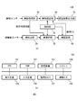
- FIG. 1A is a block diagram illustrating the overall configuration of the information processing apparatus 100.
- the information processing apparatus 100 includes a storage unit 10, a face detection unit 20, a face selection unit 30, a face recognition unit 40, a vein acquisition unit 50, a vein authentication unit 60, and an authentication result output unit. It functions as 70 and so on.
- FIG. 1B is a block diagram illustrating a hardware configuration of the information processing apparatus 100.
- the information processing device 100 includes a CPU 101, a RAM 102, a storage device 103, an interface 104, a display device 105, an input device 106, a face photographing camera 107, a vein sensor 108, and the like.
- the CPU (Central Processing Unit) 101 is a central processing unit.
- the CPU 101 includes one or more cores.
- the RAM (Random Access Memory) 102 is a volatile memory that temporarily stores a program executed by the CPU 101, data processed by the CPU 101, and the like.
- the storage device 103 is a non-volatile storage device. As the storage device 103, for example, a ROM (Read Only Memory), a solid state drive (SSD) such as a flash memory, a hard disk driven by a hard disk drive, or the like can be used.
- the storage device 103 stores the authentication program.
- the interface 104 is an interface device with an external device.
- the interface 104 is an interface device with a LAN (Local Area Network).
- the display device 105 is a display device such as an LCD (Liquid Crystal Device).
- the input device 106 is an input device such as a keyboard and a mouse.
- the face photographing camera 107 is a MOS (Metal Oxide Semiconductor) sensor, a CCD (Charged Coupled Device) sensor, or the like.
- the vein sensor 108 may include a MOS sensor, a CCD sensor, and the like, as well as near-infrared illumination and the like.
- the storage unit 10 When the CPU 101 executes the authentication program, the storage unit 10, the face detection unit 20, the face selection unit 30, the face authentication unit 40, the vein acquisition unit 50, the vein authentication unit 60, and the authentication result output unit 70 are realized.
- Hardware such as a dedicated circuit may be used as the storage unit 10, the face detection unit 20, the face selection unit 30, the face authentication unit 40, the vein acquisition unit 50, the vein authentication unit 60, and the authentication result output unit 70. ..
- the storage unit 10 stores a plurality of types of biometric information of users registered in advance.
- two different types of modality are used as a plurality of types of biometric information.
- a face feature is stored as a registered face feature and a vein feature is stored as a registered vein feature in association with each user's ID. ..
- the display device 105 displays operation information related to authentication.
- the display device 105 displays the content instructing the user to hold the palm over the vein sensor 108.
- the user inputs the palm image to the vein sensor 108 according to the instruction.
- the face photographing camera 107 acquires an image including the user's face.
- the display device 105 has directivity in the visible range of the user. Therefore, the face position of the user who visually recognizes the information displayed on the display device 105 is determined within an approximate range.
- the candidate for the person is narrowed down. After that, personal authentication is performed by performing vein authentication for the narrowed down candidates. The details will be described below.
- the face photographing camera 107 is installed in a place where the user can photograph the face of the user when the display content of the display device 105 is visually recognized by the user.
- a face photographing camera 107 is installed on the upper part of the display device 105 or the like.
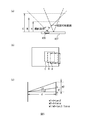
- FIGS. 3 (a) and 3 (b) are diagrams illustrating the installation location of the face photographing camera 107.
- FIG. 3A is a front view.
- FIG. 3B is a top view.
- the face photographing camera 107 is installed on the upper part of the display device 105.
- the vein sensor 108 is installed at the lower part of the display device 105 or the like.
- the shooting angle of view of the face shooting camera 107 is set to include the visible range of the display device 105 by the user. In this case, as illustrated in FIG. 3C, the visible range is included in the captured image acquired by the face photographing camera 107.
- a hood or a peep prevention film can be used as a method of limiting the visible angle range.
- the peep prevention film arranges fine louvers (feather plates) to limit the light emission direction of the display screen.
- the visible range is preferably a range that can be visually recognized by one user. Since the visible range is limited by the angle, the area of the visible range becomes wider as the distance from the face photographing camera 107 increases, and the visible range becomes visible to a plurality of users. However, in order to perform key operations, vein input, and the like, the user comes close to the input device 106 and the vein sensor 108 within reach. It is preferable that the area of the visible range at that distance is about one user.
- the storage unit 10 stores information on the visible range in the captured image acquired by the face photographing camera 107.
- FIG. 3D is a diagram illustrating information in a visible range stored in the storage unit 10.
- the visible range is a part of the captured image. For example, the range from Y1 (> 0%) to Y2 ( ⁇ 100%) on the vertical axis of the captured image, and the range from X1 (> 0%) to X2 ( ⁇ 100%) on the horizontal axis of the captured image, etc. Is set to. For example, it is assumed that the lowermost position of the vertical axis of the captured image is 0%, the uppermost end position is 100%, the leftmost position of the horizontal axis is 0%, and the rightmost position is 100%. By referring to the information in FIG. 3D, it is possible to determine the face image to be selected in the captured image.
- the user is not always positioned so as to fit within the visible range as shown in FIG. 3 (c). It is possible to visually recognize even from a position slightly shifted to the left and right as shown in FIG. 3 (e). In this case, if only the visible range is photographed, only an image in which a part of the face is missing can be obtained. It causes trouble. Therefore, it may be possible to prevent the face image from being damaged by photographing a range wider than the visible range and selecting the face detected to be the largest (larger area) in the visible range.
- FIG. 4 is a flowchart showing an example of processing of the information processing apparatus 100.
- the vein acquisition unit 50 causes the display device 105 to display information related to the vein input instruction (step S1).
- the user visually recognizes the vein input instruction displayed on the screen of the display device 105, the user holds the palm over the vein sensor 108.
- the vein acquisition unit 50 receives the palm image from the vein sensor 108, it extracts the vein feature from the palm image as a matching vein feature (step S2).
- the vein acquisition unit 50 sends the time when the palm image was acquired to the face selection unit 30 (step S3).
- steps S4 to S5 are executed in parallel with steps S1 to S3.
- the face detection unit 20 acquires a photographed image in a predetermined time range including the time received in step S3 from the face photographing camera 107 (step S4). By doing so, the accuracy of selecting the facial image of the user holding his / her hand over the vein sensor 108 is improved.
- the face detection unit 20 detects the face image position by acquiring the visible range stored in the storage unit 10 (step S5).
- the face selection unit 30 selects a target face image from the captured images (step S6). For example, when one face image is included in the visible range, the face selection unit 30 selects the face image as a target. When there are a plurality of face images included in the visible range, the face image detected to be the largest (larger area) in the visible range is selected.
- the face recognition unit 40 performs face recognition using the face image selected in step S6 (step S7).
- the face recognition unit 40 extracts a face feature as a matching face feature from the face image.
- the face feature for collation used here is data for narrowing down with an emphasis on the high speed of collation.
- the face recognition unit 40 collates the matching face feature with each registered face feature, and acquires an ID associated with the registered face feature whose similarity (narrowing score) with the matching face feature is equal to or higher than the threshold value.
- some IDs among the IDs stored in the storage unit 10 can be narrowed down as a personal candidate list.
- the vein authentication unit 60 collates the matching vein feature extracted in step S2 with the registered vein feature associated with the ID of the personal candidate list acquired in step S7 (step S8).
- the authentication result output unit 70 outputs information related to successful authentication.
- the collation score is less than the personal determination threshold value
- the authentication result output unit 70 outputs information related to the authentication failure.
- the information output by the authentication result output unit 70 is displayed on the display device 105.
- a target face image is selected from a plurality of face images based on the positions on the shot images of each of the plurality of face images included in the shot images taken by the face shooting camera 107.
- the face to be used for narrowing down can be specified, and the narrowing down time can be shortened without deteriorating the face recognition accuracy.
- the authentication time can be shortened.
- faces other than the user can be excluded from the matching target, which is also effective in terms of privacy protection.
- the storage unit 10 is an example of a storage unit that stores biometric information associated with each of a plurality of facial images.
- the matching vein feature is an example of biometric information detected by a sensor.
- This is an example of a selection unit in which the face selection unit 30 selects one of the face images from the plurality of face images based on the positions on the captured images of the plurality of face images included in the captured images captured by the camera.
- a certain face authentication unit 40 refers to a storage unit that stores biometric information associated with each of a plurality of face images, and is associated with a face image whose similarity with the selected face image satisfies the criteria. This is an example of a specific part that identifies biometric information.
- the vein authentication unit 60 receives the biometric information detected by the sensor, it is an example of an authentication unit that performs authentication by collating the received biometric information with the specified biometric information. Further, the vein authentication unit 60 is the position of the authentication unit that executes the authentication process by collating the biometric information detected by the sensor with the registered biometric information. Further, when the face image is included in the captured image captured by the camera, the face selection unit 30 and the face authentication unit 40 are among the registered biometric information based on the position of the face image on the captured image. This is an example of a determination unit for determining whether or not the biological information associated with the facial image whose similarity with the facial image satisfies the standard is to be collated with the detected biological information.
- Modification 1 It is difficult to arrange the display device 105 and the face photographing camera 107 coaxially (the center positions are the same and they face the same direction). Therefore, it is common to install the face photographing camera 107 at a place away from the center of the screen of the display device 105. For example, as illustrated in FIG. 5 (a), when installed on the upper side of the screen slightly offset from the center in the horizontal direction, the area corresponding to the visible range is the distance as illustrated in FIG. 5 (b). The position will be shifted accordingly. Therefore, the distance from the face photographing camera 107 to the face may be detected and the position of the determination area may be finely adjusted.
- the area difference between the shooting range and the visible range is caused by the difference between the shooting angle of view and the visible angle.
- w1 with respect to w0 can be expressed by the following equation (3).
- w1 / w0 tan ⁇ / tan ⁇ (3)
- the relative size of the visible range within the shooting range is constant regardless of the distance. That is, when the display device 105 and the face photographing camera 107 are coaxial, the visible range within the photographing range can be regarded as invariant. Strictly speaking, since the size of the display area is superimposed as an offset, the area is larger as the distance is shorter and smaller as the distance is far. Even when the display device 105 and the face photographing camera 107 are not coaxial, the relationship between the sizes of the regions is the same as in the case of coaxial. If it is not coaxial, the position of the area shifts with distance. The amount of deviation is determined by the difference in position between the display device 105 and the face photographing camera 107, the difference in the optical axis, and the distance.
- a screen for a projector having a high diffuse reflectance can be placed in front of the display screen and observed by the face photographing camera 107 to obtain a bright-looking area.
- the distance may be roughly determined based on the size of the face.
- the reference size is held in advance, and when the face is larger than the reference, the distance is short, and when the face is smaller than the reference, the distance is long.
- the boundary of the area is determined because the judgment of the area is not exactly whether the face is within the area, and the visual field limitation by the louver does not suddenly disappear from a certain angle, but the amount of light gradually decreases near the boundary. Since it is blurred, a short-form distance judgment is sufficient.
- the visual field limitation may be provided not only on the entire screen of the display device 105 but only in a part of the area for displaying the operation information related to the authentication. For example, an angle limit is provided so that only a part of the screen that can be seen from a wide range can be seen from the front (or a specific direction).
- the visual field limitation may be provided only in a part of the area 105b on the screen 105a of the display device 105.
- the area 105b is viewed from a visible range.
- the operation information is easy to see in the area 105b.
- FIG. 6B is a view of the area 105b viewed from outside the visible range. As shown in FIG. 6B, the operation information is difficult to see in the area 105b.
- an instruction is displayed on the normal screen and authentication is performed.
- a display can be first displayed in a visible area from a wide range, and the face can be moved to a limited area according to an instruction to use the detected face as a user.
- partial visible areas may be assigned in different directions.
- the display can be performed in a visible area in a direction corresponding to the detection position.
- the range A, the range B, and the range C are assigned in different directions.
- a display is displayed from a wide range to a viewable area, the range A is set as a visible range, then the range B is set as a visible range, and then the range C is set as a visible range. By doing so, the user moves with the switching of the visible range.
- the moved face may be used for face recognition.
- Example 1 the face image used for face authentication was selected according to the position in the image acquired by the face photographing camera 107, but the present invention is not limited to this.
- a face image used for face authentication may be selected according to the position of the operation information displayed on the display device 105.
- the vein acquisition unit 50 designates the position of the operation information of the vein sensor 108 on the screen of the display device 105 and displays it on the display device 105.
- the display device 105 has a large screen, the user moves to a position where the information can be visually recognized according to the position of the information displayed on the screen of the display device 105.
- the face selection unit 30 selects a face image located in a position range corresponding to the display position of the display device 105 in the image acquired by the face photographing camera 107 within a predetermined time range including the time when the vein image is extracted. After selecting the face image, the same processing as in Example 1 may be performed.
- the face selection unit 30 when the face selection unit 30 includes a plurality of face images in the captured image captured by the camera, the face selection unit 30 is based on the display position of the operation information on the display unit that displays the operation information related to authentication.
- This is an example of a selection unit that selects one of the face images from the plurality of face images.
- the vein authentication unit 60 is an example of an authentication unit that performs authentication using the face image selected by the selection unit.
- Storage unit 20 Face detection unit 30 Face selection unit 40 Face recognition unit 50 Venous acquisition unit 60 Venous authentication unit 70 Authentication result output unit 100 Information processing device 105 Display device 107 Face photography camera 108 Venous sensor
Landscapes
- Engineering & Computer Science (AREA)
- Theoretical Computer Science (AREA)
- Computer Security & Cryptography (AREA)
- Computer Hardware Design (AREA)
- Software Systems (AREA)
- Physics & Mathematics (AREA)
- General Engineering & Computer Science (AREA)
- General Physics & Mathematics (AREA)
- Collating Specific Patterns (AREA)
Abstract
認証方法は、カメラにより撮影された撮影画像を取得し、取得した前記撮影画像に含まれる複数の顔画像それぞれの前記撮影画像上の位置に基づき、前記複数の顔画像より何れかの顔画像を選択し、複数の顔画像それぞれに対応付けられた生体情報を記憶する記憶部を参照して、選択した前記顔画像との類似度が基準を満たす顔画像に対応付けられた生体情報を特定し、センサにより検出された生体情報を受け付けると、受け付けた前記生体情報と、特定した前記生体情報との照合による認証を行う、処理をコンピュータが実行する。
Description
本件は、認証方法、認証プログラム、および情報処理装置に関する。
第1生体情報(例えば、顔特徴)を用いた認証により候補者を絞り込み、第2生体情報(例えば、手のひら静脈特徴)を用いた認証により本人認証を行なう生体認証技術が開示されている(例えば、特許文献1参照)。
しかしながら、カメラの設置状況やユーザの利用状況によっては、同時に複数の顔が撮影される場合がある。この場合、絞り込まれる候補者が多くなってしまい、認証時間が長くなるおそれがある。候補者を少なくするために絞込み率を高くすると、顔認証の処理時間が増大するおそれがあり、顔認証の精度によっては取りこぼす(正解者が絞込みリストに入らない)おそれがある。
1つの側面では、本発明は、認証時間を短縮化することができる認証方法、認証プログラム、および情報処理装置を提供することを目的とする。
1つの態様では、認証方法は、カメラにより撮影された撮影画像を取得し、取得した前記撮影画像に含まれる複数の顔画像それぞれの前記撮影画像上の位置に基づき、前記複数の顔画像より何れかの顔画像を選択し、複数の顔画像それぞれに対応付けられた生体情報を記憶する記憶部を参照して、選択した前記顔画像との類似度が基準を満たす顔画像に対応付けられた生体情報を特定し、センサにより検出された生体情報を受け付けると、受け付けた前記生体情報と、特定した前記生体情報との照合による認証を行う、処理をコンピュータが実行する。
他の態様では、認証方法は、センサにより検出された生体情報と、登録された生体情報との照合による認証処理を実行する認証方法において、カメラにより撮影された撮影画像に顔画像が含まれる場合、前記顔画像の前記撮影画像上の位置に基づき、登録された前記生体情報のうち、前記顔画像との類似度が基準を満たす顔画像に対応付けられた生体情報を、検出した前記生体情報との照合対象とするか否かを決定する、処理をコンピュータが実行する。
他の態様では、認証方法は、カメラにより撮影された撮影画像を取得し、取得した前記撮影画像に複数の顔画像が含まれる場合、認証に関する操作情報を表示する表示部上での前記操作情報の表示位置に基づき、前記複数の顔画像より何れかの顔画像を選択し、選択した前記顔画像を用いた認証を行う、処理をコンピュータが実行する。
認証時間を短縮化することができる。
実施例の説明に先立って、一つ目のモダリティで検索集合を絞り込んで別のモダリティで利用者を特定するマルチ生体認証について説明する。
生体認証は、指紋、顔、静脈などの生体特徴を用いて本人確認をおこなう技術である。生体認証では、確認が必要な場面においてセンサによって取得した照合用生体情報と、予め登録しておいた登録生体情報とを比較(照合)し、類似度が本人判定閾値以上になるか否かを判定することで、本人確認を行なっている。
生体認証は、銀行ATM、入退室管理など様々な分野で利用されており、特に近年、スーパーマーケットやコンビニなどにおけるキャッシュレス決済にも利用され始めている。
生体認証には、IDやカード等で指定した登録生体情報との一致を確認する1:1認証と、複数の登録生体情報の中から一致する登録生体情報を検索する1:N認証とがある。店舗などでは、利便性の点から1:N認証が望まれることが多い。しかしながら、生体情報は取得状況などによって揺らぎを持つため、検索する登録生体情報の数が多くなると誤照合を起こす可能性が高くなる。このため、簡易なPINコードなどで絞込み、検索集合を十分小さくしてから1:N認証を実施するといった運用がなされている。どの程度まで小さくすると実用レベルになるかは生体認証の方式に依存する。しかしながら、簡易であってもPINコード入力は利便性を損なうため、IDやカードを必要としない生体認証システムが望まれている。
そこで、複数種類のモダリティを用い、1つ目のモダリティで検索集合を絞込み、2つ目のモダリティで利用者を特定する方式が提案されている。モダリティとは、生体特徴の種類のことであり、例えば、指紋、静脈、虹彩、顔形状、手のひら形状などである。したがって、同一の指における指紋および静脈は、異なるモダリティである。複数のモダリティを個別に入力すると利便性が悪いため、指紋入力と同時に手のひら静脈を取得する方式や、手のひら静脈入力時の顔画像を撮影する方式などが提案されている。
顔認証で絞り込み、手のひら静脈で照合を行う方式では、例えば、顔認証で候補となるN人のIDリストを作成し、得られたIDリストの集合内で手のひら静脈を用いた1:N認証が実行され、利用者を特定するといった処理が実施される。ここで、顔画像を撮影するカメラの設置状況やユーザの利用状況によっては、同時に複数の顔が撮影される場合がある。例えば、3人の顔が取得された場合、得られるIDリストはN×3人分となるため、手のひら静脈認証の照合時間を長大化させる。最初に設定されたNが、手のひら静脈認証の1:N認証の性能上限であった場合には、他人受入れのリスクが増大する。しかしながら、顔認証で1/3の人数まで絞り込もうとすると、顔認証の処理時間が増大するおそれがあり、顔認証の精度によっては取りこぼす(正解者が絞込みリストに入らない)おそれがある。
そこで、以下の実施例では、認証時間を短縮することができる情報処理装置、認証方法、および認証プログラムを提供することを目的とする。
図1(a)は、情報処理装置100の全体構成を例示するブロック図である。図1(a)で例示するように、情報処理装置100は、格納部10、顔検出部20、顔選択部30、顔認証部40、静脈取得部50、静脈認証部60、認証結果出力部70などとして機能する。
図1(b)は、情報処理装置100のハードウェア構成を例示するブロック図である。図1(b)で例示するように、情報処理装置100は、CPU101、RAM102、記憶装置103、インタフェース104、表示装置105、入力装置106、顔撮影カメラ107、静脈センサ108等を備える。
CPU(Central Processing Unit)101は、中央演算処理装置である。CPU101は、1以上のコアを含む。RAM(Random Access Memory)102は、CPU101が実行するプログラム、CPU101が処理するデータなどを一時的に記憶する揮発性メモリである。記憶装置103は、不揮発性記憶装置である。記憶装置103として、例えば、ROM(Read Only Memory)、フラッシュメモリなどのソリッド・ステート・ドライブ(SSD)、ハードディスクドライブに駆動されるハードディスクなどを用いることができる。記憶装置103は、認証プログラムを記憶している。インタフェース104は、外部機器とのインタフェース装置である。例えば、インタフェース104は、LAN(Local Area Network)とのインタフェース装置である。
表示装置105は、LCD(Liquid Crystal Device)などのディスプレイ装置などである。入力装置106は、キーボード、マウスなどの入力装置である。顔撮影カメラ107は、MOS(Metal Oxide Semiconductor)センサ、CCD(Charged Coupled Device)センサなどである。静脈センサ108は、MOSセンサ、CCDセンサなどを備えるとともに、近赤外照明などを備えていてもよい。
CPU101が認証プログラムを実行することで、格納部10、顔検出部20、顔選択部30、顔認証部40、静脈取得部50、静脈認証部60、認証結果出力部70が実現される。なお、格納部10、顔検出部20、顔選択部30、顔認証部40、静脈取得部50、静脈認証部60、認証結果出力部70として、専用の回路などのハードウェアを用いてもよい。
格納部10は、事前に登録されている利用者の複数種類の生体情報を格納している。なお、本実施例においては、複数種類の生体情報として、異なる2種類のモダリティを用いる。本実施例においては、一例として、図2で例示するように、各利用者のIDに関連付けて、顔特徴が登録顔特徴として格納されており、さらに静脈特徴が登録静脈特徴として格納されている。
本実施例においては、表示装置105が、認証に関する操作情報を表示する。例えば、表示装置105は、ユーザに、手のひらを静脈センサ108に対してかざすことを指示する内容を表示する。ユーザは、操作情報を視認すると、指示に従って手のひら画像を静脈センサ108に入力する。ユーザが手のひら画像を静脈センサ108に入力する際に、顔撮影カメラ107は、ユーザの顔を含む画像を取得する。表示装置105は、ユーザの視認可能範囲に指向性を有している。したがって、表示装置105に表示される情報を視認するユーザの顔位置は、おおよその範囲内に定まることになる。取得した画像の当該範囲内の顔画像を選択して顔認証を行なうことで、本人候補を絞り込む。その後、絞り込んだ候補を対象に静脈認証を行なうことで、本人認証を行なう。以下、詳細について説明する。
顔撮影カメラ107は、表示装置105の表示内容をユーザが視認する場合に当該ユーザの顔を撮影できる場所に設置されている。例えば、表示装置105の上部などに顔撮影カメラ107が設置されている。
図3(a)および図3(b)は、顔撮影カメラ107の設置場所を例示する図である。図3(a)は、正面図である。図3(b)は、上面図である。図3(a)および図3(b)の例では、顔撮影カメラ107は、表示装置105の上部に設置されている。静脈センサ108は、表示装置105の下部などに設置されている。顔撮影カメラ107の撮影画角は、ユーザによる表示装置105の視認可能範囲を含むように設定されている。この場合、図3(c)で例示するように、顔撮影カメラ107が取得する撮影画像内に、視認可能範囲が含まれるようになる。
視認可能な角度範囲を制限する方法として、フードや覗き見防止フィルムを用いることができる。覗き見防止フィルムは、微細なルーバー(羽板)を並べて表示画面の光の出射方向を制限するものである。ここで、視認可能範囲は、ユーザ1人が視認できる程度の範囲であることが好ましい。視認可能範囲は角度で制限されるため、顔撮影カメラ107からの距離が遠くなるほど視認可能範囲の面積は広くなり、複数のユーザが視認可能となる。しかしながら、キー操作や静脈入力などを行うためには、ユーザは、入力装置106や静脈センサ108に手の届く距離に近づくことになる。その距離における視認可能範囲の面積をユーザ1人分程度にすることが好ましい。
格納部10は、顔撮影カメラ107が取得する撮影画像内における視認可能範囲の情報を格納している。図3(d)は、格納部10に格納されている視認可能範囲の情報を例示する図である。視認可能範囲は、撮影画像内の一部の領域である。例えば、撮影画像の縦軸のうちY1(>0%)からY2(<100%)の範囲、かつ、撮影画像の横軸のうちX1(>0%)からX2(<100%)の範囲などに設定されている。例えば、撮影画像の縦軸の最下端位置が0%であり、最上端位置が100%であり、横軸の最左端位置が0%であり、最右端位置が100%であるものとする。図3(d)の情報を参照することで、撮影画像内において選択するべき顔画像を決定することができる。
ユーザは、図3(c)のような視認可能範囲にちょうど収まるように位置するとは限らない。図3(e)のように少し左右にずれた位置からでも視認は可能であり、この場合、視認可能範囲だけを撮影すると、顔の一部分が欠けた画像しか得られないため、顔認証処理に支障をきたす。このため、視認可能範囲よりも広めの範囲を撮影して、視認可能範囲内で最も大きく(面積が多く)検出された顔を選択することで、顔画像の欠損を防いでもよい。
図4は、情報処理装置100の処理の一例を表すフローチャートである。図4で例示するように、静脈取得部50は、表示装置105に、静脈入力指示に係る情報を表示させる(ステップS1)。ユーザは、表示装置105の画面に表示された静脈入力指示を視認すると、手のひらを静脈センサ108にかざす。静脈取得部50は、静脈センサ108から手のひら画像を受け付けると、手のひら画像から静脈特徴を照合用静脈特徴として抽出する(ステップS2)。静脈取得部50は、手のひら画像を取得した時刻を顔選択部30に送る(ステップS3)。
ステップS1~ステップS3と並行して、以下のステップS4~ステップS5が実行される。まず、顔検出部20は、ステップS3で受け取った時刻を含む所定時間範囲の撮影画像を顔撮影カメラ107から取得する(ステップS4)。このようにすることで、静脈センサ108に手をかざす利用者の顔画像を選択できる精度が高くなる。
次に、顔検出部20は、格納部10に格納されている視認可能範囲を取得することで、顔画像位置を検出する(ステップS5)。
ステップS3およびステップS5の実行後、顔選択部30は、撮影画像のうち、対象となる顔画像を選択する(ステップS6)。例えば、顔選択部30は、視認可能範囲に含まれる顔画像が1つである場合には、当該顔画像を対象として選択する。視認可能範囲に含まれる顔画像が複数である場合には、視認可能範囲内で最も大きく(面積が多く)検出された顔画像を対象として選択する。
次に、顔認証部40は、ステップS6で選択された顔画像を用いて顔認証を行なう(ステップS7)。まず、顔認証部40は、顔画像から顔特徴を照合用顔特徴として抽出する。ここで用いる照合用顔特徴は、照合の高速性に重点を置いた絞込み用データである。顔認証部40は、照合用顔特徴と各登録顔特徴とを照合し、照合用顔特徴との類似度(絞込みスコア)が閾値以上となる登録顔特徴に関連付けられているIDを取得する。以上の処理により、格納部10に格納されているIDのうち、一部のIDを本人候補リストとして絞り込むことができる。
次に、静脈認証部60は、ステップS2で抽出した照合用静脈特徴と、ステップS7で取得された本人候補リストのIDに関連付けられている登録静脈特徴とを照合する(ステップS8)。当該登録静脈特徴のうち1つについて照合用静脈特徴との類似度(照合スコア)が本人判定閾値以上となった場合に、認証結果出力部70は、認証成功に係る情報を出力する。当該照合スコアが本人判定閾値未満となった場合には、認証結果出力部70は、認証失敗に係る情報を出力する。認証結果出力部70によって出力された情報は、表示装置105に表示される。
本実施例によれば、顔撮影カメラ107により撮影された撮影画像に含まれる複数の顔画像それぞれの撮影画像上の位置に基づき、複数の顔画像から対象となる顔画像を選択している。それにより、絞込みに使用すべき顔を特定することができ、顔認証精度を低下させずに絞込み時間を短縮化することができる。その結果、認証時間を短縮化することができる。また、認証の対象者だけを選択して顔照合するため、利用者以外の顔を照合対象から除外することができ、プライバシー保護の点でも効果がある。
本実施例において、格納部10が、複数の顔画像それぞれに対応付けられた生体情報を記憶する記憶部の一例である。照合用静脈特徴が、センサにより検出された生体情報の一例である。顔選択部30が、カメラにより撮影された撮影画像に含まれる複数の顔画像それぞれの前記撮影画像上の位置に基づき、前記複数の顔画像より何れかの顔画像を選択する選択部の一例である、顔認証部40が、複数の顔画像それぞれに対応付けられた生体情報を記憶する記憶部を参照して、選択した前記顔画像との類似度が基準を満たす顔画像に対応付けられた生体情報を特定する特定部の一例である。静脈認証部60が、センサにより検出された生体情報を受け付けると、受け付けた前記生体情報と、特定した前記生体情報との照合による認証を行う認証部の一例である。また、静脈認証部60は、センサにより検出された生体情報と、登録された生体情報との照合による認証処理を実行する認証部の位置である。また、顔選択部30および顔認証部40は、カメラにより撮影された撮影画像に顔画像が含まれる場合、前記顔画像の前記撮影画像上の位置に基づき、登録された前記生体情報のうち、前記顔画像との類似度が基準を満たす顔画像に対応付けられた生体情報を、検出した前記生体情報との照合対象とするか否かを決定する決定部の一例である。
(変形例1)
表示装置105と顔撮影カメラ107とを同軸(中心位置が同じ、かつ同じ方向を向いている)ように配置することは困難である。したがって、表示装置105の画面中心から離れた場所に顔撮影カメラ107を設置することが一般的である。例えば、図5(a)で例示するように、中心から水平方向に少しずれた画面上辺に設置した場合は、図5(b)で例示するように、視認可能範囲に該当する領域は距離に応じてずれた位置になる。そこで、顔撮影カメラ107から顔までの距離を検出し、判定領域の位置を微調整してもよい。
表示装置105と顔撮影カメラ107とを同軸(中心位置が同じ、かつ同じ方向を向いている)ように配置することは困難である。したがって、表示装置105の画面中心から離れた場所に顔撮影カメラ107を設置することが一般的である。例えば、図5(a)で例示するように、中心から水平方向に少しずれた画面上辺に設置した場合は、図5(b)で例示するように、視認可能範囲に該当する領域は距離に応じてずれた位置になる。そこで、顔撮影カメラ107から顔までの距離を検出し、判定領域の位置を微調整してもよい。
撮影範囲と視認可能範囲との間の領域差は、撮影画角と視認可能角度との差によって生じる。例えば、図5(c)で例示するように、撮影画角を2×αとし、視認可能角度を2×βとすると、距離dだけ離れた位置の撮影範囲は、下記式(1)で表すことができる。
2×w0=d×tanα×2 (1)
2×w0=d×tanα×2 (1)
視認可能範囲の幅は、下記式(2)で表すことができる。
2×w1=d×tanβ×2 (2)
2×w1=d×tanβ×2 (2)
w0に対するw1は、下記式(3)で表すことができる。
w1/w0=tanβ/tanα (3)
w1/w0=tanβ/tanα (3)
以上のことから、撮影範囲内における視認可能範囲の領域の相対的な大きさは、距離によらず一定となる。すなわち、表示装置105と顔撮影カメラ107とが同軸の場合は、撮影範囲内における視認可能範囲は不変であるとみなすことができる。厳密には、表示領域の大きさがオフセットとして重畳するため、距離が近いほど領域は大きく、遠いほど小さくなる。表示装置105と顔撮影カメラ107とが同軸でない場合でも、領域の大きさの関係は同軸の場合と同じである。同軸でない場合は、領域の位置が距離によってずれる。ずれ量は、表示装置105と顔撮影カメラ107の位置の差と、光軸の差と、距離とによって決まる。位置および角度の差が既知である場合は計算によって求められるが、Webカメラなどのように容易に角度が変えられるものは、設置角を厳密に知ることが難しい場合がある。このような場合には、拡散反射率の高いプロジェクタ用のスクリーンなどを表示画面の前に置いて顔撮影カメラ107で観測し、明るく見える領域を求めるといった方法で確認することができる。
距離の検出は、超音波や光を用いた距離センサを設置してもよいが装置コストの増大や設置条件の制約につながる。そこで、顔の大きさにより略式に距離を判定するようにしてもよい。例えば、基準となる大きさを予め保持しておき、顔が当該基準よりも大きくなる場合には距離が短く、顔が当該基準よりも小さくなる場合には距離が長くなる。領域の判定は、顔が厳密に領域内にあるかどうかではないため、また、ルーバーによる視野制限はある角度から突然見えなくなるのではなく、境界付近で徐々に光量が低減するため領域の境界はぼやけることから、略式の距離判定でも十分である。
(変形例2)
表示装置105の画面全体ではなく、認証に関する操作情報を表示するための一部の領域だけに視野制限を設けてもよい。例えば、広い範囲から視認可能な画面の一部だけを正面(あるいは特定方向)から視認可能な角度制限を設ける。例えば、図6(a)で例示するように、表示装置105の画面105aにおいて、一部の領域105bにだけ視野制限を設けてもよい。図6(a)の例では、領域105bを視認可能範囲から見た図である。図6(a)のように、領域105bにおいて操作情報が見やすくなっている。図6(b)は、領域105bを視認可能範囲外から見た図である。図6(b)のように、領域105bにおいて操作情報が見にくくなっている。
表示装置105の画面全体ではなく、認証に関する操作情報を表示するための一部の領域だけに視野制限を設けてもよい。例えば、広い範囲から視認可能な画面の一部だけを正面(あるいは特定方向)から視認可能な角度制限を設ける。例えば、図6(a)で例示するように、表示装置105の画面105aにおいて、一部の領域105bにだけ視野制限を設けてもよい。図6(a)の例では、領域105bを視認可能範囲から見た図である。図6(a)のように、領域105bにおいて操作情報が見やすくなっている。図6(b)は、領域105bを視認可能範囲外から見た図である。図6(b)のように、領域105bにおいて操作情報が見にくくなっている。
または、撮影範囲に1人だけしか検出されない場合は、通常画面に指示を表示して認証を実施する。しかしながら、撮影範囲に複数の顔が検出された場合、まず広い範囲から視認可能な領域に表示を出し、指示に従って限定領域に移動して検出された顔を利用者とすることができる。さらに、図7で例示するように、部分的な視認可能範囲を別々の方向に割り当ててもよい。例えば、撮影範囲に1人だけが検出された場合、検出位置に合わせた方向に視認可能な領域に表示を行なうことができる。図7の例では、範囲Aと、範囲Bと、範囲Cとを別の方向に割り当てている。まず広い範囲から視野可能な領域に表示を出し、範囲Aを視認可能範囲とし、次に範囲Bを視認可能範囲とし、次に範囲Cを視認可能範囲とする。このようにすることで、ユーザは、視認可能範囲の切替に伴って移動する。移動してきた顔を顔認証に用いればよい。
実施例1では、顔撮影カメラ107が取得する画像における位置に応じて、顔認証に用いる顔画像を選択したが、それに限られない。表示装置105に表示する操作情報の位置に応じて、顔認証に用いる顔画像を選択してもよい。
図8で例示するように、静脈取得部50は、表示装置105の画面において、静脈センサ108の操作情報の位置を指定して表示装置105に表示させる。表示装置105が大画面を有している場合には、表示装置105の画面に表示される情報の位置に応じて、ユーザが当該情報を視認できる位置に移動するようになる。
例えば、「静脈センサに手をかざしてください」というメッセージが表示装置105の画面の領域αに表示された場合、そのメッセージを見ることができるのは、Aさんだけなので(Bさんは見えない)、Aさんの顔画像だけを認証対象とすればよい。一方、メッセージが表示装置105の画面の領域βに表示された場合、そのメッセージを見ることができるのはBさんだけなので(Aさんは見えない)、Bさんの顔だけを認証対象とすればよい。
顔選択部30は、静脈画像を抽出した時刻を含む所定時間範囲内に、顔撮影カメラ107が取得した画像において、表示装置105の表示位置に対応する位置範囲に位置する顔画像を選択する。顔画像を選択した後は、実施例1と同様の処理を行なえばよい。
本実施例においては、顔選択部30が、カメラにより撮影された撮影画像に複数の顔画像が含まれる場合、認証に関する操作情報を表示する表示部上での前記操作情報の表示位置に基づき、前記複数の顔画像より何れかの顔画像を選択する選択部の一例である。静脈認証部60が、前記選択部が選択した前記顔画像を用いた認証を行う認証部の一例である。
以上、本発明の実施例について詳述したが、本発明は係る特定の実施例に限定されるものではなく、特許請求の範囲に記載された本発明の要旨の範囲内において、種々の変形・変更が可能である。
10 格納部
20 顔検出部
30 顔選択部
40 顔認証部
50 静脈取得部
60 静脈認証部
70 認証結果出力部
100 情報処理装置
105 表示装置
107 顔撮影カメラ
108 静脈センサ
20 顔検出部
30 顔選択部
40 顔認証部
50 静脈取得部
60 静脈認証部
70 認証結果出力部
100 情報処理装置
105 表示装置
107 顔撮影カメラ
108 静脈センサ
Claims (20)
- カメラにより撮影された撮影画像を取得し、
取得した前記撮影画像に含まれる複数の顔画像それぞれの前記撮影画像上の位置に基づき、前記複数の顔画像より何れかの顔画像を選択し、
複数の顔画像それぞれに対応付けられた生体情報を記憶する記憶部を参照して、選択した前記顔画像との類似度が基準を満たす顔画像に対応付けられた生体情報を特定し、
センサにより検出された生体情報を受け付けると、受け付けた前記生体情報と、特定した前記生体情報との照合による認証を行う、
処理をコンピュータが実行することを特徴とする認証方法。 - 前記センサにより前記生体情報が検出された時刻を含む所定時間範囲内に前記カメラにより撮影された前記撮影画像から、前記顔画像を選択する処理を前記コンピュータが実行することを特徴とする請求項1に記載の認証方法。
- 前記カメラにより撮影される撮影画像と、前記撮影画像における所定の位置範囲との関係を格納しておき、前記位置範囲に含まれる顔画像を選択する処理を前記コンピュータが実行することを特徴とする請求項1または請求項2に記載の認証方法。
- 表示装置に、認証に関する操作情報を表示させる処理を前記コンピュータが実行し、
前記所定の位置範囲は、前記表示装置における前記操作情報の視認可能範囲に基づいて定めた範囲であることを特徴とする請求項3に記載の認証方法。 - 前記表示装置は、画面の一部に、視野制限が設けられており、
前記画面の前記一部に、前記操作情報を表示させる処理を前記コンピュータが実行することを特徴とする請求項4に記載の認証方法。 - 前記画面の前記一部に、異なる方向に視認可能角度範囲が複数設定されていることを特徴とする請求項5に記載の認証方法。
- 前記カメラから被写体までの距離を考慮して、前記撮影画像から前記顔画像を選択する処理を、前記コンピュータが実行することを特徴とする請求項1~請求項6のいずれか一項に記載の認証方法。
- センサにより検出された生体情報と、登録された生体情報との照合による認証処理を実行する認証方法において、
カメラにより撮影された撮影画像に顔画像が含まれる場合、前記顔画像の前記撮影画像上の位置に基づき、登録された前記生体情報のうち、前記顔画像との類似度が基準を満たす顔画像に対応付けられた生体情報を、検出した前記生体情報との照合対象とするか否かを決定する、
処理をコンピュータが実行することを特徴とする認証方法。 - 前記センサにより前記生体情報が検出された時刻を含む所定時間範囲内に前記カメラにより撮影された前記撮影画像に含まれる前記顔画像の前記撮影画像上の位置に基づき、登録された前記生体情報のうち、前記顔画像との類似度が基準を満たす顔画像に対応付けられた生体情報を、検出した前記生体情報との照合対象とするか否かを決定する、処理を前記コンピュータが実行することを特徴とする請求項8に記載の認証方法。
- 前記カメラにより撮影される撮影画像と、前記撮影画像における所定の位置範囲との関係を格納しておき、前記所定の位置範囲に前記顔画像が含まれる場合、登録された前記生体情報のうち、前記顔画像との類似度が基準を満たす顔画像に対応付けられた生体情報を、検出した前記生体情報との照合対象とするか否かを決定する、処理をコンピュータが実行することを特徴とする請求項8または請求項9に記載の認証方法。
- 表示装置に、認証に関する操作情報を表示させる処理を前記コンピュータが実行し、
前記所定の位置範囲は、前記表示装置における前記操作情報の視認可能範囲に基づいて定めた範囲であることを特徴とする請求項10に記載の認証方法。 - 前記表示装置は、画面の一部に、視認制限が設けられており、
前記画面の一部に、前記操作情報を表示させる処理を前記コンピュータが実行することを特徴とする請求項11に記載の認証方法。 - 前記画面の一部に、異なる方向に視認可能角度範囲が複数設定されていることを特徴とする請求項12に記載の認証方法。
- カメラにより撮影された撮影画像を取得し、
取得した前記撮影画像に複数の顔画像が含まれる場合、認証に関する操作情報を表示する表示部上での前記操作情報の表示位置に基づき、前記複数の顔画像より何れかの顔画像を選択し、
選択した前記顔画像を用いた認証を行う、
処理をコンピュータが実行することを特徴とする認証方法。 - カメラにより撮影された撮影画像に含まれる複数の顔画像それぞれの前記撮影画像上の位置に基づき、前記複数の顔画像より何れかの顔画像を選択する選択部と、
複数の顔画像それぞれに対応付けられた生体情報を記憶する記憶部を参照して、選択した前記顔画像との類似度が基準を満たす顔画像に対応付けられた生体情報を特定する特定部と、
センサにより検出された生体情報を受け付けると、受け付けた前記生体情報と、特定した前記生体情報との照合による認証を行う認証部と、を備えることを特徴とする情報処理装置。 - センサにより検出された生体情報と、登録された生体情報との照合による認証処理を実行する認証部と、
カメラにより撮影された撮影画像に顔画像が含まれる場合、前記顔画像の前記撮影画像上の位置に基づき、登録された前記生体情報のうち、前記顔画像との類似度が基準を満たす顔画像に対応付けられた生体情報を、検出した前記生体情報との照合対象とするか否かを決定する決定部と、を備えることを特徴とする情報処理装置。 - カメラにより撮影された撮影画像に複数の顔画像が含まれる場合、認証に関する操作情報を表示する表示部上での前記操作情報の表示位置に基づき、前記複数の顔画像より何れかの顔画像を選択する選択部と、
前記選択部が選択した前記顔画像を用いた認証を行う認証部と、を備えることを特徴とする情報処理装置。 - コンピュータに、
カメラにより撮影された撮影画像を取得し、
取得した前記撮影画像に含まれる複数の顔画像それぞれの前記撮影画像上の位置に基づき、前記複数の顔画像より何れかの顔画像を選択し、
複数の顔画像それぞれに対応付けられた生体情報を記憶する記憶部を参照して、選択した前記顔画像との類似度が基準を満たす顔画像に対応付けられた生体情報を特定し、
センサにより検出された生体情報を受け付けると、受け付けた前記生体情報と、特定した前記生体情報との照合による認証を行う、
処理を実行させることを特徴とする認証プログラム。 - センサにより検出された生体情報と、登録された生体情報との照合による認証処理を実行する認証プログラムにおいて、
コンピュータに、
カメラにより撮影された撮影画像に顔画像が含まれる場合、前記顔画像の前記撮影画像上の位置に基づき、登録された前記生体情報のうち、前記顔画像との類似度が基準を満たす顔画像に対応付けられた生体情報を、検出した前記生体情報との照合対象とするか否かを決定する、
処理を実行させることを特徴とする認証プログラム。 - コンピュータに、
カメラにより撮影された撮影画像を取得し、
取得した前記撮影画像に複数の顔画像が含まれる場合、認証に関する操作情報を表示する表示部上での前記操作情報の表示位置に基づき、前記複数の顔画像より何れかの顔画像を選択し、
選択した前記顔画像を用いた認証を行う、
処理を実行させることを特徴とする認証プログラム。
Priority Applications (5)
| Application Number | Priority Date | Filing Date | Title |
|---|---|---|---|
| EP20934943.0A EP4152181A4 (en) | 2020-05-13 | 2020-05-13 | AUTHENTICATION METHOD, AUTHENTICATION PROGRAM, AND INFORMATION PROCESSING DEVICE |
| JP2022522167A JP7364965B2 (ja) | 2020-05-13 | 2020-05-13 | 認証方法、認証プログラム、および情報処理装置 |
| CN202080100444.6A CN115485683A (zh) | 2020-05-13 | 2020-05-13 | 认证方法、认证程序以及信息处理装置 |
| PCT/JP2020/019108 WO2021229717A1 (ja) | 2020-05-13 | 2020-05-13 | 認証方法、認証プログラム、および情報処理装置 |
| US17/963,588 US20230047264A1 (en) | 2020-05-13 | 2022-10-11 | Authentication method, storage medium, and information processing apparatus |
Applications Claiming Priority (1)
| Application Number | Priority Date | Filing Date | Title |
|---|---|---|---|
| PCT/JP2020/019108 WO2021229717A1 (ja) | 2020-05-13 | 2020-05-13 | 認証方法、認証プログラム、および情報処理装置 |
Related Child Applications (1)
| Application Number | Title | Priority Date | Filing Date |
|---|---|---|---|
| US17/963,588 Continuation US20230047264A1 (en) | 2020-05-13 | 2022-10-11 | Authentication method, storage medium, and information processing apparatus |
Publications (1)
| Publication Number | Publication Date |
|---|---|
| WO2021229717A1 true WO2021229717A1 (ja) | 2021-11-18 |
Family
ID=78525460
Family Applications (1)
| Application Number | Title | Priority Date | Filing Date |
|---|---|---|---|
| PCT/JP2020/019108 WO2021229717A1 (ja) | 2020-05-13 | 2020-05-13 | 認証方法、認証プログラム、および情報処理装置 |
Country Status (5)
| Country | Link |
|---|---|
| US (1) | US20230047264A1 (ja) |
| EP (1) | EP4152181A4 (ja) |
| JP (1) | JP7364965B2 (ja) |
| CN (1) | CN115485683A (ja) |
| WO (1) | WO2021229717A1 (ja) |
Families Citing this family (1)
| Publication number | Priority date | Publication date | Assignee | Title |
|---|---|---|---|---|
| US20210406353A1 (en) * | 2020-06-29 | 2021-12-30 | Zkteco Usa | System and method for biometric authentication |
Citations (5)
| Publication number | Priority date | Publication date | Assignee | Title |
|---|---|---|---|---|
| JP2004062846A (ja) * | 2002-07-31 | 2004-02-26 | Waimachikku Kk | 個人識別装置の入力装置 |
| JP2007072861A (ja) * | 2005-09-08 | 2007-03-22 | Omron Corp | なりすまし検出装置及び顔認証装置 |
| JP2018116353A (ja) * | 2017-01-16 | 2018-07-26 | 高知信用金庫 | 金融機関における利用者特定システム及び取引方法 |
| JP2018197980A (ja) * | 2017-05-24 | 2018-12-13 | シャープ株式会社 | 画像表示装置、画像形成装置、制御プログラムおよび制御方法 |
| JP2019128880A (ja) | 2018-01-26 | 2019-08-01 | 富士通フロンテック株式会社 | 認証システム、認証装置、認証プログラム、および認証方法 |
Family Cites Families (2)
| Publication number | Priority date | Publication date | Assignee | Title |
|---|---|---|---|---|
| WO2020070821A1 (ja) * | 2018-10-03 | 2020-04-09 | 富士通株式会社 | 生体認証装置、生体認証方法、及び生体認証プログラム |
| CN111125799B (zh) * | 2019-12-24 | 2023-06-23 | 联想(北京)有限公司 | 用于显示屏的控制方法和装置 |
-
2020
- 2020-05-13 WO PCT/JP2020/019108 patent/WO2021229717A1/ja unknown
- 2020-05-13 CN CN202080100444.6A patent/CN115485683A/zh active Pending
- 2020-05-13 EP EP20934943.0A patent/EP4152181A4/en not_active Withdrawn
- 2020-05-13 JP JP2022522167A patent/JP7364965B2/ja active Active
-
2022
- 2022-10-11 US US17/963,588 patent/US20230047264A1/en not_active Abandoned
Patent Citations (5)
| Publication number | Priority date | Publication date | Assignee | Title |
|---|---|---|---|---|
| JP2004062846A (ja) * | 2002-07-31 | 2004-02-26 | Waimachikku Kk | 個人識別装置の入力装置 |
| JP2007072861A (ja) * | 2005-09-08 | 2007-03-22 | Omron Corp | なりすまし検出装置及び顔認証装置 |
| JP2018116353A (ja) * | 2017-01-16 | 2018-07-26 | 高知信用金庫 | 金融機関における利用者特定システム及び取引方法 |
| JP2018197980A (ja) * | 2017-05-24 | 2018-12-13 | シャープ株式会社 | 画像表示装置、画像形成装置、制御プログラムおよび制御方法 |
| JP2019128880A (ja) | 2018-01-26 | 2019-08-01 | 富士通フロンテック株式会社 | 認証システム、認証装置、認証プログラム、および認証方法 |
Also Published As
| Publication number | Publication date |
|---|---|
| JPWO2021229717A1 (ja) | 2021-11-18 |
| EP4152181A4 (en) | 2023-06-07 |
| CN115485683A (zh) | 2022-12-16 |
| EP4152181A1 (en) | 2023-03-22 |
| JP7364965B2 (ja) | 2023-10-19 |
| US20230047264A1 (en) | 2023-02-16 |
Similar Documents
| Publication | Publication Date | Title |
|---|---|---|
| JP4924603B2 (ja) | 顔認証装置、顔認証方法およびプログラム | |
| JP4862447B2 (ja) | 顔認識システム | |
| US6700998B1 (en) | Iris registration unit | |
| US8280120B2 (en) | Fraud resistant biometric financial transaction system and method | |
| CN110443016B (zh) | 信息防泄露方法、电子装置及存储介质 | |
| WO2018042996A1 (ja) | 生体検知装置 | |
| EP3594916A1 (en) | Atm with biometric security | |
| US20100157088A1 (en) | Authentication apparatus and authentication method | |
| JP6028453B2 (ja) | 画像処理装置、画像処理方法および画像処理プログラム | |
| JP2015138449A (ja) | 個人認証装置、個人認証方法及びプログラム | |
| JP4992517B2 (ja) | 顔照合装置 | |
| JP4899552B2 (ja) | 認証装置、認証方法、認証プログラム、これを記録したコンピュータ読み取り可能な記録媒体 | |
| JP2010108200A (ja) | 個人認証装置及び個人認証方法 | |
| JP4862518B2 (ja) | 顔登録装置、顔認証装置および顔登録方法 | |
| JP2005202730A (ja) | 生体照合を用いた個人認証装置、個人認証方法、及び通行制御装置 | |
| JP2006309562A (ja) | 生体情報登録装置 | |
| TWM566865U (zh) | 基於臉部辨識進行驗證的交易系統 | |
| WO2021229717A1 (ja) | 認証方法、認証プログラム、および情報処理装置 | |
| JP2019159573A (ja) | ログイン支援システム | |
| TWI661398B (zh) | 基於臉部辨識進行驗證的交易系統及其方法 | |
| JP6187262B2 (ja) | 生体情報処理装置、生体情報処理方法及び生体情報処理用コンピュータプログラム | |
| JP7207521B2 (ja) | 認証方法、認証装置、プログラム | |
| JP6947202B2 (ja) | 照合システム | |
| JP4671845B2 (ja) | 個人認証システム、および個人認証プログラム | |
| JP2018169943A (ja) | 顔認証処理装置、顔認証処理方法及び顔認証処理システム |
Legal Events
| Date | Code | Title | Description |
|---|---|---|---|
| 121 | Ep: the epo has been informed by wipo that ep was designated in this application |
Ref document number: 20934943 Country of ref document: EP Kind code of ref document: A1 |
|
| ENP | Entry into the national phase |
Ref document number: 2022522167 Country of ref document: JP Kind code of ref document: A |
|
| NENP | Non-entry into the national phase |
Ref country code: DE |
|
| ENP | Entry into the national phase |
Ref document number: 2020934943 Country of ref document: EP Effective date: 20221213 |