WO2021221009A1 - Terminal device, method, and integrated circuit - Google Patents
Terminal device, method, and integrated circuit Download PDFInfo
- Publication number
- WO2021221009A1 WO2021221009A1 PCT/JP2021/016603 JP2021016603W WO2021221009A1 WO 2021221009 A1 WO2021221009 A1 WO 2021221009A1 JP 2021016603 W JP2021016603 W JP 2021016603W WO 2021221009 A1 WO2021221009 A1 WO 2021221009A1
- Authority
- WO
- WIPO (PCT)
- Prior art keywords
- mbs
- information
- layer
- rrc
- pdcp
- Prior art date
Links
Images


Classifications
-
- H—ELECTRICITY
- H04—ELECTRIC COMMUNICATION TECHNIQUE
- H04W—WIRELESS COMMUNICATION NETWORKS
- H04W4/00—Services specially adapted for wireless communication networks; Facilities therefor
- H04W4/06—Selective distribution of broadcast services, e.g. multimedia broadcast multicast service [MBMS]; Services to user groups; One-way selective calling services
-
- H—ELECTRICITY
- H04—ELECTRIC COMMUNICATION TECHNIQUE
- H04W—WIRELESS COMMUNICATION NETWORKS
- H04W72/00—Local resource management
- H04W72/30—Resource management for broadcast services
-
- H—ELECTRICITY
- H04—ELECTRIC COMMUNICATION TECHNIQUE
- H04W—WIRELESS COMMUNICATION NETWORKS
- H04W76/00—Connection management
- H04W76/40—Connection management for selective distribution or broadcast
Definitions
- the present invention relates to terminal devices, methods, and integrated circuits.
- the present application claims priority with respect to Japanese Patent Application No. 2020-79034 filed in Japan on April 28, 2020, the contents of which are incorporated herein by reference.
- 3GPP 3rd Generation Partnership Project
- E-UTRA Evolved Universal Terrestrial Radio Access
- RAT Radio Access Technology
- 3GPP 3GPP is conducting technical studies and standardization of E-UTRA extended technology.
- E-UTRA is also referred to as Long Term Evolution (LTE: registered trademark), and the extended technology may be referred to as LTE-Advanced (LTE-A) or LTE-Advanced Pro (LTE-A Pro).
- LTE Long Term Evolution
- LTE-A LTE-Advanced
- LTE-A Pro LTE-Advanced Pro
- NR New Radio or NR Radio access
- RAT Radio Access Technology
- 3GPP RP-193248 "New Work Item on NR Multicast and Broadcast Services”
- 3GPP TS 23.501 v15.3.0 System Architecture for the 5G System; Stage 2
- 3GPP TS 36.300 v15.3.0 “Evolved Universal Terrestrial Radio Access (E-UTRA) and Evolved Universal Terrestrial Radio Access Network Network; Network Network; Network Network”.
- E-UTRA Evolved Universal Terrestrial Radio Access
- 3GPP TS 36.331 v15.4.0 "Evolved Universal Terrestrial Radio Access (E-UTRA); Radio Access Control (RRC); Protocol specialties” 3GPP TS 36.323 v15.3.0, “Evolved Universal Terrestrial Radio Access (E-UTRA); Packet Data Convergence Protocol (PDCP) specification” 3GPP TS 36.322 v15.3.0, “Evolved Universal Terrestrial Radio Access (E-UTRA); Radio Link Control (RLC) protocol specialization” 3GPP TS 36.321 v15.3.0, “Evolved Universal Terrestrial Radio Access (E-UTRA); Medium Access Control (MAC) protocol specification" 3GPP TS 37.340v 15.8.0, “Evolved Universal Terrestrial Radio Access (E-UTRA) and NR; Multi-Connectivity; Stage 2" 3GPP TS 38.300v 15.3.0, “NR; NR and NG-RAN Overall description; Stage 2" 3GPP TS 38.331 v15
- MBMS Multicast Broadcast Multicast Service
- MBSFN Multicast Broadcast Single Frequency Network
- SC-PTM Single Cell Point-To-Multipoint
- multicast / broadcast data is transmitted using PMCH (Physical Multicast Channel) in units of MBSFN (Multicast-Broadcast Single-Freequency Network) area consisting of a plurality of cells.
- PMCH Physical Multicast Channel
- MBSFN Multicast-Broadcast Single-Freequency Network
- SC-PTM Multicast data is transmitted using PDSCH (Physical Downlink Shared Channel) on a cell-by-cell basis.
- MBS Multicast Broadcast Service
- Non-Patent Document 1 a multicast / broadcast service (Multicast Broadcast Service: MBS) as an extension technology of NR is being studied.
- MBS Multicast Broadcast Service
- Non-Patent Document 1 When MBS is performed via NR, it is necessary to consider NR-specific technology different from E-UTRA, core network standardized for 5G, and the like. However, the detailed operation for efficiently receiving MBS using NR has not yet been studied.
- One aspect of the present invention has been made in view of the above circumstances, and one of the objects is to provide a terminal device, a method, and an integrated circuit capable of efficiently receiving MBS using NR.
- one aspect of the present invention is a terminal device that communicates with a base station device, and includes a receiving unit and a processing unit that receive an RRC message including setting information of a multicast broadcast service (MBS) from the base station device.
- the MBS setting information includes MBS session information
- the MBS session information includes PDU session information
- the processing unit is based on the terminal device starting receiving the MBS session. Therefore, a wireless bearer for MBS is established, and a process of notifying a part or all of the MBS session information to the upper layer is performed.
- one aspect of the present invention is a method of a terminal device that communicates with a base station device, in which an RRC message including setting information of a multicast broadcast service (MBS) is received from the base station device and the MBS is set.
- the information includes MBS session information
- the MBS session information includes PDU session information
- the terminal device establishes a wireless bearer for MBS based on starting reception of the MBS session, and the MBS session. Notify the upper layer of some or all of the information.
- the terminal device can efficiently receive MBS using NR.
- the schematic diagram of the communication system which concerns on each embodiment of this invention.
- the block diagram which shows the structure of the terminal apparatus in each embodiment of this invention.
- the block diagram which shows the structure of the base station apparatus in each embodiment of this invention.
- the ASN An example of one description.
- the ASN An example of one description.
- ASN Representing a field and / or an information element included in SIB20 (System Information Block Type 20). The figure which shows an example of 1 description.
- ASN Representing a field and / or information element included in an SC-PTM configuration message (SCPTMCconfiguration). The figure which shows an example of 1 description.
- LTE (and LTE-A, LTE-A Pro) and NR may be defined as different radio access technologies (Radio Access Technology: RAT).
- RAT Radio Access Technology: RAT
- NR may also be defined as a technique included in LTE.
- LTE may be defined as a technique included in NR.
- LTE that can be connected to NR by Multi Radio Dual connectivity may be distinguished from conventional LTE.
- LTE having a core network of 5GC may be distinguished from conventional LTE having a core network of EPC.
- This embodiment may be applied to NR, LTE and other RATs.
- terms related to LTE and NR will be used, but the present embodiment may be applied in other techniques using other terms.
- E-UTRA in the present embodiment may be replaced with the term LTE
- LTE may be replaced with the term E-UTRA.
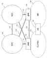
- FIG. 1 is a schematic diagram of a communication system according to each embodiment of the present invention.
- E-UTRA100 is a wireless access technology described in Non-Patent Document 3 and the like, and is composed of a cell group (Cell Group: CG) composed of one or a plurality of frequency bands.
- the eNB (E-UTRAN Node B) 102 is a base station device of the E-UTRA100.
- the EPC (Evolved Packet Core) 104 is a core network described in Non-Patent Document 14 and the like, and was designed as a core network for the E-UTRA100.
- the interface 112 is an interface between the eNB 102 and the EPC 104, and has a control plane (Control Plane: CP) through which control signals pass and a user plane (User Plane: UP) through which user data passes.
- Control Plane: CP Control Plane
- User Plane: UP User Plane
- NR106 is a wireless access technology described in Non-Patent Document 9 and the like, and is composed of a cell group (Cell Group: CG) composed of one or a plurality of frequency bands.
- gNB (g Node B) 108 is a base station device of NR106.
- the 5GC110 is a core network described in Non-Patent Document 2 and the like, and is designed as a core network for NR106, but may be used as a core network for E-UTRA100 having a function of connecting to the 5GC110.
- the E-UTRA 100 may include the E-UTRA 100 having a function of connecting to the 5GC110.
- Interface 114 is an interface between eNB 102 and 5GC110, interface 116 is an interface between gNB108 and 5GC110, interface 118 is an interface between gNB108 and EPC104, interface 120 is an interface between eNB102 and gNB108, and interface 124 is an interface between EPC104 and 5GC110.
- the interface 114, interface 116, interface 118, interface 120, interface 124, and the like may be CP only, UP only, or an interface that passes through both CP and UP. Further, the interface 114, the interface 116, the interface 118, the interface 120, the interface 124, and the like may not exist depending on the communication system provided by the telecommunications carrier.
- UE 122 is a terminal device corresponding to any or all of E-UTRA100 and NR106.
- RB Radio Bearer
- the radio bearer used for CP is called a signaling radio bearer (SRB: Signaling Radio Bearer)
- SRB Signaling Radio Bearer
- DRB Data Radio Bearer Each RB is assigned an RB identifier (RB Identity or RB ID) and is uniquely identified.
- the SRB RB identifier is called an SRB identifier (SRB Identity or SRB ID)
- DRB RB identifier is called a DRB identifier (DRB Identity or DRB ID).
- each DRB established between the UE 122 and any or all of the E-UTRA 100 and the NR 106 is further equipped with the EPC 104. It is uniquely associated with each EPS (Evolved Patent System) bearer that passes through the inside. Each EPS bearer is assigned an EPS bearer identifier (Identity or ID) and is uniquely identified. Also, the same QoS is guaranteed for the data passing through the same EPS bearer.
- EPS Evolved Patent System
- Non-Patent Document 9 when the core network to which the UE 122 is connected is 5GC110, one or more DRBs established between the UE 122 and any or all of the E-UTRA100 and the NR106 Furthermore, it is linked to one of the PDU (Packet Data Unit) sessions established in 5GC110. There is one or more QoS flows in each PDU session. Each DRB may be associated (mapped) with one or more QoS flows existing in the associated PDU session, or may not be associated with any QoS flow. Each PDU session is identified by a PDU session identifier (Identity, or ID). Each QoS flow is identified by a QoS flow identifier. Further, the same QoS is guaranteed for the data passing through the same QoS flow.
- PDU session identifier Identity, or ID
- Each QoS flow is identified by a QoS flow identifier. Further, the same QoS is guaranteed for the data passing through the same QoS flow.
- EPC104 does not have any or all of the PDU sessions and QoS flows
- 5GC110 does not have EPS bearers.
- the UE 122 When the UE 122 is connected to the EPC 104, the UE 122 has information on the EPS bearer, but not any or all of the PDU session and the QoS flow.
- the UE 122 When the UE 122 is connected to the 5GC110, the UE 122 has information on any or all of the PDU session and the QoS flow, but not the EPS bearer.
- the eNB 102 and / or the gNB 108 is also simply referred to as a base station device, and the UE 122 is also simply referred to as a terminal device.
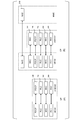
- FIG. 2 is a protocol stack (Protocol Stack) diagram of UP and CP of the terminal device and the base station device in the E-UTRA wireless access layer (radio access layer) in each embodiment of the present invention.
- Protocol stack Protocol Stack
- FIG. 2A is a protocol stack diagram of UP used when the UE 122 communicates with the eNB 102 in the E-UTRA100.
- the PHY (Physical layer) 200 is a wireless physical layer (radio physical layer), and provides a transmission service to an upper layer (upper layer) by using a physical channel (Physical Channel).
- the PHY200 is connected to a higher-level MAC (Medium Access Control layer) 202, which will be described later, by a transport channel (Transport Channel). Data moves between MAC202 and PHY200 via the transport channel. Data is transmitted and received between the UE 122 and the PHY of the eNB 102 via the radio physical channel.
- RNTI Radio Network Temporary Identity
- the MAC202 is a medium access control layer (medium access control layer) that maps various logical channels (logical channels) to various transport channels.
- the MAC 202 is connected to a higher-level RLC (Radio Link Control layer) 204, which will be described later, by a logical channel (logical channel).
- the logical channel is roughly classified according to the type of information to be transmitted, and is divided into a control channel for transmitting control information and a traffic channel for transmitting user information.
- the MAC202 has a function of controlling PHY200 for performing intermittent reception (DRX: Discontinuus Reception) and / or (and / or) and intermittent transmission (DTX: Discontinuus Transmission), and a function of executing a random access (Random Access) procedure.
- DRX Discontinuus Reception
- DTX Discontinuus Transmission
- UL Uplink
- DL Downlink
- BCCH Broadcast Control Channel
- SI System Information
- the PCCH may be a downlink logical channel for carrying a calling message.
- the PCCH may also be used to notify changes in system information.
- the CCCH may be a logical channel for transmitting control information between the UE 122 and the eNB 102.
- CCCH may be used when the UE 122 does not have an RRC (Radio Resource Control) connection described later.
- RRC Radio Resource Control
- CCCH may also be used between a base station device and a plurality of terminal devices.
- the DCCH (Dedicated Control Channel) is a logical channel for transmitting dedicated control information between the UE 122 and the eNB 102 in a one-to-one (point-to-point) bi-directional manner. good.
- the dedicated control information may be control information dedicated to each terminal device.
- the DCCH may be used when the UE 122 has an RRC (Radio Resource Control) connection with the eNB 102, which will be described later.
- RRC Radio Resource Control
- the DTCH (Dedicated Traffic Channel) may be a logical channel for transmitting user data on a one-to-one basis (point-to-point) between the UE 122 and the eNB 102.
- the MTCH (Multicast Traffic Channel) may be a point-to-multipoint downlink channel for transmitting data from the eNB 102 to the UE 122.
- the SC-MTCH may be used by the UE 122 only when the UE 122 receives the MBMS.
- the MCCH may be a one-to-multipoint downlink channel for sending MBMS control information for one or more MTCHs from the eNB 102 to the UE 122.
- the MCCH may be used by the UE 122 only when the UE 122 receives the MBMS or is interested in the UE 122 receiving the MBMS.
- the SC-MTCH (Single Cell Multicast Traffic Channel) may be a one-to-multipoint downlink channel for transmitting data from the eNB 102 to the UE 122 using the SC-PTM.
- the SC-MTCH may be used by the UE 122 only when the UE 122 receives the MBMS using the SC-PTM (Single Cell Point-To-Multipoint).
- the SC-MCCH (Single Cell Multicast Control Channel) is a one-to-multipoint downlink channel for sending MBMS control information for one or more SC-MTCHs from the eNB 102 to the UE 122. You may.
- the SC-MCCH may be used by the UE 122 only when the UE 122 is interested in receiving the MBMS using the SC-PTM, or the UE 122 is interested in receiving the MBMS using the SC-PTM.
- the CCCH may be mapped to UL-SCH (Uplink Shared Channel), which is an uplink transport channel.
- UL-SCH Uplink Shared Channel
- the DCCH may be mapped to UL-SCH (Uplink Shared Channel), which is an uplink transport channel.
- UL-SCH Uplink Shared Channel
- the DTCH may be mapped to UL-SCH (Uplink Shared Channel), which is an uplink transport channel.
- UL-SCH Uplink Shared Channel
- BCCH may be mapped to BCH (Broadcast Channel), which is a downlink transport channel, and / or DL-SCH (Downlink Shared Channel).
- BCH Broadcast Channel
- DL-SCH Downlink Shared Channel
- the PCCH may be mapped to a PCH (Paging Channel) which is a downlink transport channel.
- PCH Packet Control Channel
- the CCCH may be mapped to the DL-SCH (Downlink Shared Channel), which is a downlink transport channel.
- DL-SCH Downlink Shared Channel
- the DCCH may be mapped to the DL-SCH (Downlink Shared Channel), which is a downlink transport channel.
- DL-SCH Downlink Shared Channel
- the DTCH may be mapped to the DL-SCH (Downlink Shared Channel), which is a downlink transport channel.
- DL-SCH Downlink Shared Channel
- MTCH may be mapped to MCH (Multicast Channel) which is a downlink transport channel.
- MCH Multicast Channel
- the MCCH may be mapped to the MCH (Multicast Channel), which is a downlink transport channel.
- MCH Multicast Channel
- the SC-MTCH may be mapped to the DL-SCH (Downlink Shared Channel), which is a downlink transport channel.
- DL-SCH Downlink Shared Channel
- the SC-MTCH may be mapped to the DL-SCH (Downlink Shared Channel), which is a downlink transport channel.
- DL-SCH Downlink Shared Channel
- the RLC204 divides the data received from the upper PDCP (Packet Data Convergence Protocol Layer) 206, which will be described later, and adjusts the data size so that the lower layer (lower layer) can appropriately transmit the data. It is a wireless link control layer (wireless link control layer).
- the RLC204 has three modes: a transparent mode (TM: Transparent Mode), a non-response mode (UM: Unlockedged Mode), and a response mode (AM: Acknowledged Mode).
- TM Transparent Mode
- UM Unlockedged Mode
- AM Acknowledged Mode
- the TM does not divide the data received from the upper layer and does not add the RLC header.
- the UM divides the data received from the upper layer, adds the RLC header, and the like, but does not control the retransmission of the data.
- the AM divides the data received from the upper layer, adds the RLC header, controls the retransmission of the data, and the like.
- the retransmission control function may be a function for guaranteeing the QoS (Quality of Service) required by each data.
- Information on undelivered data sent from the receiving side of RLC to the transmitting side when controlling data retransmission is called a status report.
- the instruction sent from the transmitting side of RLC to the receiving side to prompt the status report is called a poll.
- the data transmitted to the lower layer by TM may be referred to as TMD PDU
- the data transmitted to the lower layer by UM may be referred to as UMD PDU
- the data transmitted to the lower layer by AM may be referred to as AMD PDU. be. (Non-Patent Document 6).
- PDCP206 is a packet data convergence protocol layer (packet data convergence protocol layer) for efficiently transmitting user data such as an IP packet (IP Packet) in a wireless section.
- the PDCP206 may have a header compression function that compresses unnecessary control information.
- the PDCP206 may also have a data encryption function. Further, PDCP206 may have a function of reordering (Non-Patent Document 5).
- the data processed by MAC202, RLC204, and PDCP206 are called MAC PDU (Protocol Data Unit), RLC PDU, and PDU PDU, respectively.
- MAC PDU Protocol Data Unit
- RLC PDU Packet Data Unit
- PDU PDU Packet Data Unit
- the data passed from the upper layer to MAC202, RLC204, and PDCP206, or the data passed to the upper layer are called MAC SDU (Service Data Unit), RLC SDU, and PDU SDU, respectively.
- the divided RLC SDU is called an RLC SDU segment.
- PDCP PDUs are also called PDCP DATA PDU (PDCP Data PDU, PDU Data PDU) and PDU CONTROL PDU (PDCP Control PDU, PDCP control PDU, PDCP control PDU), respectively, in order to distinguish between data use and control use. good.
- RLC PDUs may be called RLC DATA PDUs (RLC Data PDUs, RLC data PDUs) and RLC CONTROL PDUs (RLC Control PDUs, RLC control PDUs, RLC control PDUs), respectively, in order to distinguish between data and control PDUs. good.
- FIG. 2B is a protocol stack diagram of the CP used when the UE 122 communicates with the eNB 102 and the MME (mobility management entity) which is a logical node that provides functions such as authentication and mobility management in the E-UTRA100. ..
- MME mobility management entity
- RRC Radio Resource Control layer
- NAS Non Access Stratum
- the RRC208 performs processing such as establishment, reestablishment, suspension (suspend), and cancellation (resume) of the RRC connection, and resetting of the RRC connection, for example, a radio bearer (RB) and a cell group (Cell Group).
- Wireless link control layer wireless link control
- the RB may be divided into a Signaling Radio Bearer (SRB) and a Data Radio Bearer (DRB), and the SRB is used as a route for transmitting an RRC message which is control information. You may.
- the DRB may be used as a route for transmitting user data.
- Each RB may be set between the eNB 102 and the RRC208 of the UE 122. Further, the portion of the RB composed of the RLC 204 and the logical channel (logical channel) may be referred to as an RLC bearer (Non-Patent Document 4).
- NAS layer that carries the signal between the MME and the UE 122
- layers layers of the PHY200, MAC202, RLC204, PDCP206, and RRC208 that carry the signal and data between the UE 122 and the eNB 102.
- AS layers Access Stratum layers
- SRB0 may be an SRB for an RRC message using the CCCH (Control Control Channel) of the logical channel.
- SRB1 may be an SRB for RRC messages (which may contain piggybacked NAS messages) and for NAS messages before the establishment of SRB2, all used by the logical channel DCCH (Dedicated Control Channel). May be done.
- SRB2 may be an SRB for NAS messages, and all logical channel DCCHs may be used. Further, SRB2 may have a lower priority than SRB1.
- the RRC message may be sent using the BCCH of the logical channel, the PCCH of the logical channel, or the MCCH of the logical channel.
- the RRC message sent using BCCH may include, for example, the master information block (Master Information Block) described in Non-Patent Document 4, or includes each type of system information block (System Information Block). It may contain other RRC messages.
- the RRC message sent using BCCH may include, for example, the paging message described in Non-Patent Document 4, or may include other RRC messages.
- the RRC message sent using the MCCH may include, for example, the MBSFN (Multicast Broadcast Single Frequency Network) area setting (MBSFNAreaConfiguration) described in Non-Patent Document 4, and includes the MBMS Continuing Request. It may contain other RRC messages.
- MBSFN Multicast Broadcast Single Frequency Network
- MBSFNAreaConfiguration Multicast Broadcast Single Frequency Network area setting
- MAC202, RLC204, PDCP206, and RRC208 is an example, and a part or all of each function may not be implemented. Further, a part or all of the functions of each layer may be included in another layer.
- the IP layer, the TCP (Transmission Control Protocol) layer (TCP layer) above the IP layer, the UDP (User Datagram Protocol) layer (UDP layer), the application layer (application layer), etc. are the upper layers of the PDCP layer (application layer). Upper layer) (not shown).
- the RRC layer and NAS (non Access Stratum) layer are also higher layers of the PDCP layer (not shown).
- the PDCP layer is an RRC layer, a NAS layer, an IP layer, a TCP (Transmission Control Protocol) layer above the IP layer, a UDP (User Datagram Protocol) layer, and a lower layer (lower layer) of the application layer.
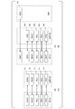
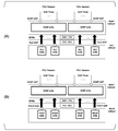
- FIG. 3 is a protocol stack (Protocol Stack) diagram of the UP and CP of the terminal device and the base station device in the NR radio access layer in each embodiment of the present invention.
- Protocol stack Protocol Stack
- FIG. 3A is a protocol stack diagram of UP used when UE 122 communicates with gNB 108 in NR106.
- the PHY (Physical layer) 300 is a wireless physical layer (radio physical layer) of NR, and a transmission service may be provided to an upper layer by using a physical channel (Physical Channel).
- the PHY 300 may be connected to a higher-level MAC (Medium Access Control layer) 302 described later by a transport channel (Transport Channel). Data may be moved between MAC 302 and PHY 300 via the transport channel. Data may be transmitted and received between the UE 122 and the PHY of the gNB 108 via the radio physical channel.
- RNTI Radio Network Temporary Identity
- the following physical channels may be used for wireless communication between the terminal device and the base station device.
- PBCH Physical Broadcast Channel
- PDCCH Physical Downlink Control Channel
- PDSCH Physical Downlink Shared Channel
- PUCCH Physical Uplink Control Channel
- PUSCH Physical Uplink Shared Channel
- PRACH Physical Random Access Channel
- PBCH is used to notify the system information required by the terminal device.
- PBCH may be used to notify the time index (SSB-Index) within the period of the block of the synchronization signal (also referred to as SS / PBCH block).
- SSB-Index time index within the period of the block of the synchronization signal
- the PDCCH is used for transmitting (or carrying) downlink control information (Downlink Control Information: DCI) in downlink wireless communication (wireless communication from the base station device 3 to the terminal device).
- DCI Downlink Control Information
- one or more DCIs are defined for the transmission of downlink control information. That is, the field for downlink control information is defined as DCI and mapped to the information bits.
- the PDCCH is transmitted in the PDCCH candidate.
- the terminal device monitors a set of PDCCH candidates (candidates) in the serving cell. Monitoring means attempting to decode the PDCCH according to a certain DCI format.
- Certain DCI formats may be used for scheduling PUSCH in serving cells. PUSCH may be used for transmission of user data, transmission of RRC messages, and the like.
- the PUCCH may be used to transmit uplink control information (Uplink Control Information: UCI) in uplink wireless communication (wireless communication from a terminal device to a base station device).
- the uplink control information may include channel state information (CSI: Channel State Information) used to indicate the status of the downlink channel.
- the uplink control information may include a scheduling request (SR: Scheduling Request) used for requesting a UL-SCH resource.
- the uplink control information may include HARQ-ACK (Hybrid Automatic Repeat ACKnowledgement).
- the PDSCH may be used for transmitting downlink data (DL-SCH: Downlink Shared Channel) from the MAC layer. Further, in the case of a downlink, it is also used for transmission of system information (SI: System Information) and random access response (RAR: Random Access Response).
- SI System Information
- RAR Random Access Response
- PUSCH may be used to transmit HARQ-ACK and / or CSI together with uplink data (UL-SCH: Uplink Shared Channel) or uplink data from the MAC layer. PUSCH may also be used to transmit CSI only or HARQ-ACK and CSI only. That is, PUSCH may be used to transmit only UCI. PDSCH or PUSCH may also be used to transmit RRC signaling (also referred to as RRC messages) and MAC control elements.
- RRC signaling also referred to as RRC messages
- the RRC signaling transmitted from the base station device may be a common signaling to a plurality of terminal devices in the cell.
- the RRC signaling transmitted from the base station device may be dedicated signaling (also referred to as “dedicated signaling)” for a certain terminal device. That is, the information specific to the terminal device (UE specific) may be transmitted to a certain terminal device using dedicated signaling.
- PUSCH may be used for transmission of UE capability (UE Capacity) on the uplink.
- PRACH may be used to transmit a random access preamble.
- the PRACH is used to indicate an initial connection establishment procedure, a handover procedure, a connection re-station procedure, synchronization (timing adjustment) for uplink transmission, and a request for PUSCH (UL-SCH) resources. May be used for.
- the MAC302 is a medium access control layer (medium access control layer) that maps various logical channels (logical channels) to various transport channels.
- the MAC 302 may be connected to a higher-level RLC (Radio Link Control layer) 304, which will be described later, by a logical channel (logical channel).
- the logical channel is roughly classified according to the type of information to be transmitted, and may be divided into a control channel for transmitting control information and a traffic channel for transmitting user information.
- the MAC 302 has a function of controlling PHY300 for intermittent transmission (DRX / DTX), a function of executing a random access (Random Access) procedure, a function of notifying transmission power information, a function of performing HARQ control, and the like. You may have it (Non-Patent Document 13).
- UL Uplink
- DL Downlink
- BCCH Broadcast Control Channel
- SI System Information
- the PCCH may be a downlink logical channel for carrying a calling message.
- the CCCH may be a logical channel for transmitting control information between the UE 122 and the gNB 108.
- CCCH may be used when the UE 122 does not have an RRC connection.
- CCCH may also be used between a base station device and a plurality of terminal devices.
- the DCCH (Dedicated Control Channel) is a logical channel for transmitting dedicated control information between the UE 122 and the gNB 108 in a one-to-one (point-to-point) bi-directional manner. good.
- the dedicated control information may be control information dedicated to each terminal device.
- DCCH may be used when the UE 122 has an RRC connection.
- the DTCH (Dedicated Traffic Channel) may be a logical channel for transmitting user data on a one-to-one basis (point-to-point) between the UE 122 and the gNB 108.
- the DTCH may exist on both the uplink and the downlink.
- the CCCH may be mapped to UL-SCH (Uplink Shared Channel), which is an uplink transport channel.
- UL-SCH Uplink Shared Channel
- the DCCH may be mapped to UL-SCH (Uplink Shared Channel), which is an uplink transport channel.
- UL-SCH Uplink Shared Channel
- the DTCH may be mapped to UL-SCH (Uplink Shared Channel), which is an uplink transport channel.
- UL-SCH Uplink Shared Channel
- BCCH may be mapped to BCH (Broadcast Channel), which is a downlink transport channel, and / or DL-SCH (Downlink Shared Channel).
- BCH Broadcast Channel
- DL-SCH Downlink Shared Channel
- the PCCH may be mapped to a PCH (Paging Channel) which is a downlink transport channel.
- PCH Packet Control Channel
- the CCCH may be mapped to the DL-SCH (Downlink Shared Channel), which is a downlink transport channel.
- DL-SCH Downlink Shared Channel
- the DCCH may be mapped to the DL-SCH (Downlink Shared Channel), which is a downlink transport channel.
- DL-SCH Downlink Shared Channel
- the DTCH may be mapped to the DL-SCH (Downlink Shared Channel), which is a downlink transport channel.
- DL-SCH Downlink Shared Channel
- the RLC 304 is a wireless link control that divides the data received from the upper PDCP (Packet Data Convergence Protocol Layer) 306, which will be described later, and adjusts the data size so that the lower layer can appropriately transmit the data. It is a layer (wireless link control layer).
- the RLC 304 has three modes: a transparent mode (TM: Transparent Mode), a non-response mode (UM: Unlockedged Mode), and a response mode (AM: Acknowledged Mode).
- TM Transparent Mode
- UM Unlockedged Mode
- AM Acknowledged Mode
- the TM does not divide the data received from the upper layer and does not add the RLC header.
- the UM divides the data received from the upper layer, adds the RLC header, and the like, but does not control the retransmission of the data.
- the AM divides the data received from the upper layer, adds the RLC header, controls the retransmission of the data, and the like.
- the retransmission control function may be a function for guaranteeing the QoS (Quality of Service) required by each data.
- Information on undelivered data sent from the receiving side of RLC to the transmitting side when controlling data retransmission is called a status report.
- the instruction sent from the transmitting side of RLC to the receiving side to prompt the status report is called a poll.
- the data transmitted to the lower layer by TM may be referred to as TMD PDU
- the data transmitted to the lower layer by UM may be referred to as UMD PDU
- the data transmitted to the lower layer by AM may be referred to as AMD PDU. be.
- PDCP306 is a packet data convergence protocol layer (packet data convergence protocol layer) that efficiently transmits user data such as IP packets (IP Packet) in a wireless section.
- the PDCP306 may have a header compression function that compresses unnecessary control information.
- the PDCP306 may also have data encryption and data integrity protection functions. Further, PDCP306 may have a function of reordering (Non-Patent Document 11).
- the SDAP (Service Data Application Protocol) 310 is associated with the downlink QoS flow sent from the 5GC110 to the terminal device via the base station device and the DRB (mapping: mapping), and from the terminal device to the base station device via the base station device. It is a service data adaptation protocol layer (service data adaptation protocol layer) having a function of mapping between the QoS flow of the uplink sent to the 5GC110 and the DRB and storing the mapping rule information (Non-Patent Document 16).
- MAC PDU Protocol Data Unit
- RLC PDU Physical Location
- PDCP PDU Physical Location
- SDAP PDU Secure Data Unit
- RLC SDU Service Data Unit
- PDU SDU Physical Location
- SDA P SDU Service Data Unit
- SDAP PDUs are called SDAP DATA PDUs (SDAP Data PDUs, SDAP data PDUs) and SDAP CONTROL PDUs (SDAP Control PDUs, SDAP control PDUs, SDAP control PDUs), respectively, in order to distinguish between data and control PDUs. Is also good.
- PDCP PDUs are also called PDCP DATA PDU (PDCP Data PDU, PDU Data PDU) and PDU CONTROL PDU (PDCP Control PDU, PDCP control PDU, PDCP control PDU), respectively, in order to distinguish between data use and control use. good.
- RLC PDUs are called RLC DATA PDUs (RLC Data PDUs, RLC data PDUs) and RLC CONTROL PDUs (RLC Control PDUs, RLC control PDUs, RLC control PDUs), respectively, in order to distinguish between data and control PDUs. Is also good.
- FIG. 3B is a protocol stack diagram of the CP used when the UE 122 communicates with the gNB 108 and the AMF (Access and Mobility Management function), which is a logical node that provides functions such as authentication and mobility management, in the NR 106. ..
- AMF Access and Mobility Management function
- RRC Radio Resource Control layer
- NAS Non Access Stratum
- the RRC308 performs processing such as establishment, re-establishment, suspension (suspend), and suspension (resume) of the RRC connection, and resetting of the RRC connection, for example, a radio bearer (RB) and a cell group (Cell Group).
- Wireless link control layer wireless link control
- the RB may be divided into a Signaling Radio Bearer (SRB) and a Data Radio Bearer (DRB), and the SRB is used as a route for transmitting an RRC message which is control information. You may.
- the DRB may be used as a route for transmitting user data.
- Each RB may be set between the gNB 108 and the RRC308 of the UE 122. Further, the portion of the RB composed of the RLC 304 and the logical channel (logical channel) may be referred to as an RLC bearer (Non-Patent Document 10).
- the NAS layer that carries the signal between the AMF and the UE 122
- some or all layers of the PHY300, MAC302, RLC304, PDCP306, RRC308, SDAP310 that carry the signal and data between the UE 122 and the gNB 108. May be referred to as an AS (Access Stratum) layer.
- AS Access Stratum
- SRB0 may be an SRB for an RRC message using the CCCH (Control Control Channel) of the logical channel.
- SRB1 may be an SRB for RRC messages (which may contain piggybacked NAS messages) and for NAS messages before the establishment of SRB2, all used by the logical channel DCCH (Dedicated Control Channel). May be done.
- SRB2 may be an SRB for NAS messages, and all logical channel DCCHs may be used. Further, SRB2 may have a lower priority than SRB1.
- the SRB3 may be an SRB for a specific RRC message when the UE 122 is set to EN-DC, NGEN-DC, NR-DC, etc., which will be described later, and all DCCHs of the logical channel may be used. .. In addition, other SRBs may be prepared for other uses.
- the RRC message may be sent using the BCCH of the logical channel, or may be sent using the PCCH of the logical channel.
- the RRC message sent using BCCH may include, for example, the master information block (Master Information Block: MIB) described in Non-Patent Document 10, or each type of system information block (System Information Block: SIB). May be included, or other RRC messages may be included.
- the RRC message sent using BCCH may include, for example, the paging message described in Non-Patent Document 10, or may include other RRC messages.
- MAC302, RLC304, PDCP306, SDAP310, and RRC308 are examples, and some or all of the functions may not be implemented. Further, a part or all of the functions of each layer (each layer) may be included in another layer (layer).
- the upper layer (not shown) of the AS layer may be called a PDU layer (PDU layer) as described in Non-Patent Document 2.
- the PDU layer may include any or all of an IP layer, a TCP (Transmission Control Protocol) layer above the IP layer, a UDP (User Datagram Protocol) layer, and other layers.
- the application layer may be an upper layer of the PDU layer, or may be included in the PDU layer.
- the PDU layer may be an upper layer with respect to the user plane of the AS layer.
- the RRC layer and the NAS (non Access Stratum) layer may also be an upper layer of any or all of the SDAP layer and the PDCP layer (not shown).
- any or all of the SDAP layer and PDCP layer are the RRC layer, the NAS layer, the IP layer, and the TCP (Transmission Control Protocol) layer above the IP layer, the UDP (User Datagram Protocol) layer, and the application layer. It becomes a lower layer of any or all of.
- SIP Session Initiation Protocol
- SDP Session Description Protocol
- IMS IP Multimedia Subsystem
- RTP Real-time Transport Protocol
- RTCP Real-time Transport Protocol
- HTTP HyperText Transfer Protocol
- various media codecs, etc. May belong to the application layer.
- the physical layer, MAC layer, RLC layer, PDCP layer, and SDAP layer of the terminal device may be established, set, and controlled by the RRC layer of the terminal device, or all of them may be performed. Further, the RRC layer of the terminal device may establish and / or set the physical layer, the MAC layer, the RLC layer, the PDCP layer, and the SDAP layer according to the RRC message transmitted from the RRC layer of the base station device. Further, the MAC layer (MAC layer), RLC layer (RLC layer), PDCP layer (PDCP layer), and SDAP layer (SDAP layer) are divided into MAC sublayer (MAC sublayer), RLC sublayer (RLC sublayer), and PDCP sublayer, respectively. It may be called a layer (PDCP sublayer) or a SDAP sublayer (SDAP sublayer).
- MAC sublayer MAC sublayer
- RLC sublayer RLC sublayer
- SDAP sublayer SDAP sublayer
- each layer belonging to the AS layer set in any or all of the terminal device and the base station device, or the function of each layer may be called an entity. That is, the physical layer (PHY layer), MAC layer, RLC layer, and PDCP layer in which any or all of establishment, setting, and control are performed on any or all of the terminal device and the base station device. , SDAP layer, and RRC layer, or the function of each layer may be referred to as a physical entity (PHY entity), a MAC entity, an RLC entity, a PDCP entity, a SDAP entity, and an RRC entity, respectively. Further, one or more entities of each layer may be included in each layer.
- the PDCP entity and the RLC entity may be established, set, and controlled for each radio bearer, or all of them may be performed.
- the MAC entity may be established, set, and controlled for each cell group, or all of them may be performed.
- the SDAP entity may be established, configured, and controlled for each PDU session, either or all.
- the COUNT value may be used when performing encryption or integrity protection processing in the PDCP layer or PDCP entity.
- the COUNT value may be composed of an HFN (Hyper Frame Number) and a sequence number (SN: Sequence Number) added to the header of the PDCP PDU.
- the sequence number may be incremented by 1 each time a PDCP DATA PDU is generated by the transmitting PDCP layer or PDCP entity.
- the HFN may be added by 1 each time the sequence number reaches the maximum value.
- state variables state variables
- Non-Patent Document 11 It may be a state variable named TX_NEXT described in Non-Patent Document 11.
- B In this PDCP entity, a state variable indicating the sequence number of the PDCP SDU to be transmitted next. It may be a state variable named Next_PDCP_TX_SN described in Non-Patent Document 5.
- C A state variable representing an HFN value used to generate a COUNT value for a PDCP PDU in this PDCP entity. It may be a state variable named TX_HFN described in Non-Patent Document 5.
- D A state variable indicating the COUNT value of the PDCP SDU that is expected to be received next on the receiving side of the PDCP entity.
- Non-Patent Document 11 It may be a state variable named RX_NEXT described in Non-Patent Document 11.
- E A state variable indicating the sequence number of the PDCP SDU that is expected to be received next on the receiving side of this PDCP entity. It may be a state variable named Next_PDCP_RX_SN described in Non-Patent Document 5.
- F A state variable representing an HFN value used to generate a COUNT value for a received PDCP PDU in this PDCP entity. It may be a state variable named RX_HFN described in Non-Patent Document 5.
- reordering means that the PDCP SDU is stored in the reception buffer, and the PDCP SDU is placed in the upper layer in the order of the COUNT values obtained from the header information of the PDCP DATA PDU. It may be a process for delivery. Reordering means that when the COUNT value of the received PDCP data PDU is the COUNT value of the first PDCP SDU that has not yet been passed to the upper layer, the stored PDCP SDUs are sent to the upper layer in the order of the COUNT values. It may include the process of handing over to.
- the received PDCP data PDU is used as the PDCP SDU. It may be a process of converting to and storing in the reordering buffer, receiving all the lost PDCP data PDUs, converting them to PDCP SDUs, and then passing them to the upper layer.
- a reordering timer (a timer named t-Reordering described in Non-Patent Document 11 or Non-Patent Document 5) may be used to detect the loss of PDCP data PDU.
- state variables A state variable indicating the COUNT value of the PDCP SDU that is expected to be received next on the receiving side of the PDCP entity. It may be a state variable named RX_NEXT described in Non-Patent Document 11.
- B A state variable indicating the sequence number of the PDCP SDU that is expected to be received next on the receiving side of this PDCP entity. It may be a state variable named Next_PDCP_RX_SN described in Non-Patent Document 5.
- C A state variable representing an HFN value used to generate a COUNT value for a received PDCP PDU in this PDCP entity.
- Non-Patent Document 5 It may be a state variable named RX_HFN described in Non-Patent Document 5.
- D A state variable indicating the COUNT value of the first PDCP PDU among the PDCP SDUs waiting to be received that have not been delivered to the upper layer on the receiving side of the PDCP entity. It may be a state variable named RX_DELIV described in Non-Patent Document 11.
- E A state variable indicating the sequence number of the PDCP PDU of the PDCP SDU that was finally delivered to the upper layer on the receiving side of this PDCP entity. It may be a state variable named Last_Submitted_PDCP_RX_SN described in Non-Patent Document 5.
- (F) A state variable indicating the COUNT value next to the COUNT value of the PDCP PDU that started the reordering timer on the receiving side of the PDCP entity. It may be a state variable named RX_REORD described in Non-Patent Document 11 or a state variable named Reading_PDCP_RX_COUNT described in Non-Patent Document 5.
- MAC202, RLC204, PDCP206, and RRC208 are used as MAC for E-UTRA or MAC for LTE, and E-UTRA, respectively.
- MAC302, RLC304, PDCP306, and RRC308 may be referred to as NR MAC, NR RLC, NR RLC, and NR RRC, respectively.
- it may be described using spaces such as E-UTRA PDCP, LTE PDCP, and NR PDCP.
- the eNB 102, gNB 108, EPC 104, and 5GC 110 may be connected via the interface 112, the interface 116, the interface 118, the interface 120, and the interface 114. Therefore, the RRC208 in FIG. 2 may be replaced with the RRC308 in FIG. 3 in order to support various communication systems.
- the PDCP206 of FIG. 2 may be replaced with the PDCP306 of FIG.
- the RRC308 of FIG. 3 may include the function of the RRC208 of FIG.
- the PDCP306 of FIG. 3 may be the PDCP206 of FIG.
- NR PDCP may be used as the PDCP even when the UE 122 communicates with the eNB 102.
- the UE 122 connected to the EPC or the 5GC may be in the RRC_CONNECTED state when the RRC connection is established (RRC connection has been studied).
- the state in which the RRC connection is established may include a state in which the UE 122 holds a part or all of the UE context described later. Further, the state in which the RRC connection is established may include a state in which the UE 122 can transmit and / or receive unicast data.
- the UE 122 may be in the RRC_INACIVE state (if the UE 122 is connected to 5GC) when the RRC connection is dormant. If not in those cases, UE 122 may be in the RRC_IDLE state.
- the suspension of the RRC connection may be started by E-UTRAN.
- the UE 122 transitions to the RRC_IDLE state by holding the AS context of the UE and the identifier (resumeIdentity) used for returning.
- the UE 122 holds the AS context of the UE, the return of the RRC connection is permitted by E-UTRAN, and the UE 122 needs to transition from the RRC_IDLE state to the RRC_CONNECTED state, the hibernated RRC Restoration of the connection may be initiated by a higher layer (eg NAS layer).
- a higher layer eg NAS layer
- the definition of pause may be different between the UE 122 connected to the EPC and the UE 122 connected to the 5GC. Further, when the UE 122 is connected to the EPC (when it is hibernating in the RRC_IDLE state) and when the UE 122 is connected to the 5GC (when it is hibernating in the RRC_INACIVE state), the UE 122 returns from hibernation. All or part of the procedure to be performed may be different.
- the RRC_CONNECTED state, RRC_INACTIVE state, and RRC_IDLE state may be referred to as a connected state (connected mode), an inactive state (inactive mode), and an idle state (idle mode), respectively, and the RRC connected state (RRC connected mode).
- RRC inactive state RRC inactive mode
- RRC hibernation state RRC idle mode
- the AS context of the UE held by the UE 122 is the current RRC setting, the current security context, the PDCP state including the ROHC (RObust Header Compression) state, and the C-RNTI (Cell Radio) used in the PCell of the connection source (Source). It may be information including all or a part of the Network Temperature Identity), the cell identifier (cellIdentity), and the physical cell identifier of the PCell of the connection source.
- the AS context of the UE held by any or all of the eNB 102 and the gNB 108 may include the same information as the AS context of the UE held by the UE 122, or the information included in the AS context of the UE held by the UE 122. May contain information different from.
- the security context is the encryption key at AS level, NH (Next Hop parameter), NCC (Next Hop Chaining Counter parameter) used for deriving the access key of the next hop, the identifier of the selected AS level encryption algorithm, and replay protection. It may be information that includes all or part of the counters used for.
- the handover may be a process in which the UE 122 in the RRC connection state changes the serving cell.
- the handover may be performed when the UE 122 receives an RRC message instructing the handover from the eNB 102 and / or the gNB 108.
- the RRC message instructing the handover is an RRC connection including a parameter instructing the handover (for example, an information element named MobilityControlInfo described in Non-Patent Document 4 or an information element named ReconnectionWithSync described in Non-Patent Document 10).
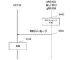
- FIG. 4 is a diagram showing an example of a flow of procedures for various settings in RRC208 and / or (and / or) RRC308 in each embodiment of the present invention.
- FIG. 4 is an example of a flow in which an RRC message is sent from the base station apparatus (eNB 102 and / or gNB 108) to the terminal apparatus (UE122).
- the base station apparatus creates an RRC message (step S400).
- the creation of the RRC message in the base station device may be performed when the base station device distributes broadcast information (SI: System Information) or paging information, or the base station device processes a specific terminal device.
- SI System Information
- the base station device processes a specific terminal device.
- security settings for example, security settings, RRC connection reset (wireless bearer processing (establishment, change, release, etc.), cell group processing (establishment, addition, change, etc.)) , Release, etc.), measurement setting, handover setting, etc.), RRC connection state release, etc. may be performed.
- the RRC message may also be used for a handover command to a different RAT.
- the RRC message includes information (parameters) for various information notifications and settings.
- information for various information notifications and settings.
- these parameters are referred to as fields and / or information elements, and are referred to as ASN. It is described using a description method called 1 (Abust Syntax Notation One).
- the base station apparatus then transmits the created RRC message to the terminal apparatus (step S402).
- the terminal device performs processing when processing such as setting is required according to the received RRC message (step S404).
- the creation of the RRC message is not limited to the above example, and may be created for other purposes as described in Non-Patent Document 4 and Non-Patent Document 10.
- the RRC message may be used for setting the Dual Connectivity (DC) or the Multi-Radio Dual Connectivity (MR-DC) described in Non-Patent Document 8.
- DC Dual Connectivity
- MR-DC Multi-Radio Dual Connectivity
- Dual Connectivity is a cell group composed of two base station devices (nodes), that is, a master cell group (Master Cell Group: MCG) and a secondary node (Technology) composed of a master node (Master Node: MN). It may be a technique for performing data communication using both radio resources of a secondary cell group (Secondary Cell Group: SCG) configured by Node: SN). Further, the master node and the secondary node may be the same node (same base station device). Further, as described in Non-Patent Document 8, MR-DC is a cell group of both E-UTRA and NR RAT (Radio Access Technology) cells for each RAT and assigned to the UE, and both MCG and SCG.
- E-UTRA E-UTRA
- NR RAT Radio Access Technology
- the master node refers to the main RRC functions related to MR-DC, such as the addition of secondary nodes, the establishment, change, and release of RB, and the addition, change, release, and handover of MCG.
- the secondary node may be a base station having some RRC functions such as SCG change and release.
- the RRC of the RAT on the master node side may be used to set both the MCG and the SCG.
- the core network is EPC104 and the master node is eNB102 (also referred to as extended eNB102)
- the MR-DC is EN-DC (E-UTRA-NR Dual Reference)
- the core network is 5GC110
- the master node is In NGEN-DC (NG-RAN E-UTRA-NR Dual Connectivity), which is MR-DC in the case of eNB 102
- the RRC message of E-UTRA described in Non-Patent Document 4 is transmitted and received between the eNB 102 and the UE 122. May be done.
- the RRC message may include not only LTE (E-UTRA) setting information but also NR setting information described in Non-Patent Document 10. Further, the RRC message transmitted from the eNB 102 to the UE 122 may be transmitted from the eNB 102 to the UE 122 via the gNB 108. Further, the configuration of this RRC message may be used for E-UTRA / 5GC in which the eNB 102 (extended eNB) uses 5GC as the core network.
- the RRC message of NR described in Non-Patent Document 10 may be transmitted and received between gNB 108 and UE 122.
- the RRC message may include not only the NR setting information but also the LTE (E-UTRA) setting information described in Non-Patent Document 4.
- the RRC message transmitted from the gNB 108 to the UE 122 may be transmitted from the gNB 108 to the UE 122 via the eNB 102.
- the RRC message for E-UTRA transmitted from the eNB 102 to the UE 122 may include the RRC message for NR, or for NR transmitted from gNB 108 to the UE 122.
- the RRC message may include an RRC message for E-UTRA.
- a network configuration in which the master node is the eNB 102 and the EPC 104 is the core network may be called E-UTRA / EPC.
- a network configuration in which the master node is an eNB 102 and the 5GC110 is a core network may be called E-UTRA / 5GC.
- a network configuration in which the master node is gNB108 and the 5GC110 is the core network may be referred to as NR or NR / 5GC.
- this name does not have to be limited to the case where DC is set.
- the above-mentioned master node may refer to a base station device that communicates with a terminal device.
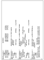
- FIG. 7 shows, in FIG. 4, the ASN. 1 This is an example of description.
- FIG. 8 shows an ASN. 1 This is an example of description. Not limited to FIGS. 7 and 8, the ASN.
- ⁇ omitted> and ⁇ omitted> are ASN. Indicates that other information is omitted, not a part of the notation of 1. Note that the information element may be omitted even in places where there is no description of ⁇ omitted> or ⁇ omitted>.
- ASN An example of 1 is ASN.
- the notation method is not correctly followed, and an example of the parameter of the message regarding the resetting of the RRC connection in the embodiment of the present invention is described, and other names and other notations may be used.
- ASN The first example shows only an example relating to the main information closely related to one embodiment of the present invention, in order to avoid complicating the explanation.
- the parameters described in 1 may be referred to as information elements without distinguishing them into fields, information elements, and the like. Further, in the embodiment of the present invention, the ASN. Parameters such as fields and information elements described in 1 may be referred to as information.
- the message regarding the resetting of the RRC connection may be an RRC resetting message in NR or an RRC connection resetting message in E-UTRA.
- the information element represented by RadioBearerConfig in FIG. 7 is an information element related to the setting of wireless bearers such as SRB and DRB, and includes a PDCP setting information element and a SDAP setting information element described later.
- the information element represented by SRB-ToAd Mod which is included in the information element represented by RadioBearerConfig, may be information indicating the SRB (signaling radio bearer) setting, and may be the SRB setting information element or the signaling radio bearer setting information element. In other words. Further, the information element represented by SRB-ToAdModList may be a list of information indicating the SRB setting.
- the information element represented by DRB-ToAddMod included in the information element represented by RadioBearerConfig may be information indicating a DRB (data radio bearer) setting, and may be a DRB setting information element or a data radio bearer setting information element.
- the information element represented by DRB-ToAdModList may be a list of information indicating the DRB setting.
- any or all of the SRB setting and the DRB setting may be paraphrased as a wireless bearer setting.
- the information element represented by SRB-Identity is the information of the SRB identifier (SRB Identity) of the SRB to be added or changed, and is an identifier that uniquely identifies the SRB in each terminal device. Is also good.
- the information element represented by SRB-Identity in the SRB setting information element may be paraphrased as an SRB identifier information element, a radio bearer identifier information element, or a signaling radio bearer identifier information element.
- the information element represented by DRB-Identity in the DRB setting information element is the information of the DRB identifier (DRB Identity) of the DRB to be added or changed, and is an identifier that uniquely identifies the DRB in each terminal device. Is also good.
- the information element represented by DRB-Identity in the DRB setting information element may be paraphrased as a DRB identifier information element, a radio bearer identifier information element, or a data radio bearer identifier information element.
- the value of the DRB identifier is an integer value from 1 to 32 in the example of FIG. 7, but another value may be taken. For DC, the DRB identifier is unique within the scope of UE 122.
- the information element represented by cnAscation may be an information element indicating whether EPC104 or 5GC110 is used for the core network, and may be paraphrased as a core network association information element. .. That is, when the UE 122 connects to the EPC, the DRB is associated with the EPS bearer identifier information element (eps-Bearer Identity) in the cnAssociation or the EPS bearer identifier (EPS bearer identity) which is the value of the EPS bearer identifier information element.
- EPS bearer identifier information element eps-Bearer Identity
- EPS bearer identity EPS bearer identifier
- the DRB is a SDAP entity set according to the SDAP setting information element (sdap-Config) described later, or a PDU session information element or PDU session described later included in the SDAP setting information element. It may be associated with the PDU session identifier, which is the value of the information element, or the PDU session indicated by the PDU session information element.
- the information represented by cnAscation includes the EPS bearer identifier information element (eps-BearerIdentity) when EPC104 is used for the core network such as when EN-DC is used, and when the core network 5GC110 is used, that is, When EN-DC is not used, an information element (sdap-Config) indicating the SDAP setting may be included.
- eps-BearerIdentity the EPS bearer identifier information element
- an information element indicating the SDAP setting may be included.
- the information element represented by sdap-Config may be information on the setting or resetting of the SDAP entity that determines the method of mapping the QoS flow and DRB when the core network is 5GC110. It may be paraphrased as an SDAP setting information element.
- the field or information element represented by the pdu-session or PDU-SessionID included in the SDAP setting information element is a radio corresponding to the value of the radio bearer identifier information element included in the DRB setting information element including the SDAP setting information element.
- the PDU session identifier of the PDU session described in Non-Patent Document 2 to which the QoS flow associated with the bearer belongs may be used, and may be paraphrased as the PDU session identifier information element.
- the value of the PDU session identifier information element may be a non-negative integer. Further, in each terminal device, a plurality of DRB identifiers may correspond to one PDU session identifier.
- the information element indicated by mappedQoS-FlowsToAdd included in the SDAP setting information element corresponds to the wireless bearer corresponding to the value of the wireless bearer identifier information element included in the DRB setting information element including the SDAP setting information element (map). It may be information indicating a list of QoS flow identifier (QFI: QoS Flow Identity) information elements of the QoS flow to be added or additionally supported (map), and may be paraphrased as the QoS flow information element to be added. be.
- QFI QoS Flow Identity
- the above-mentioned QoS flow may be the QoS flow of the PDU session indicated by the PDU session information element included in the SDAP setting information element.
- the information element indicated by mappedQoS-FlowsToReleasure included in the SDAP setting information element corresponds to the wireless bearer corresponding to the value of the wireless bearer identifier information element included in the DRB setting information element including the present SDAP setting information element ( Of the MAP) QoS flows, it may be information indicating a list of QoS flow identifier (QFI: QoS Flow Identity) information elements of the QoS flow for which the correspondence is released, and the QoS flow information element to be released.
- QFI QoS Flow Identity
- the above-mentioned QoS flow may be the QoS flow of the PDU session indicated by the PDU session information element included in the SDAP setting information element.
- the information element represented by QFI may be a QoS flow identifier that uniquely identifies a QoS flow described in Non-Patent Document 2, and may be paraphrased as a QoS flow identifier information element.
- the value of the QoS flow identifier information element may be a non-negative integer. Further, the value of the QoS flow identifier information element may be unique to the PDU session.
- the SDAP setting information element includes an uplink header information element indicating whether or not an uplink SDAP header exists in the uplink data transmitted via the set DRB, and the SDAP setting information element via the set DRB.
- a downlink header information element indicating whether or not a downlink SDAP header exists in the downlink data received by the user, and a default bearer information element indicating whether or not the set DRB is the default wireless bearer (default DRB). Etc. may be included.
- the SRB setting information element and the information element represented by pdcp-Config or PDCP-Config in the DRB setting information element are NR for establishing or changing PDCP306 for SRB and / or DRB. It may be an information element related to the setting of the PDCP entity, and may be paraphrased as a PDCP setting information element.
- the information elements related to the setting of the NR PDCP entity include an information element indicating the size of the uplink sequence number, an information element indicating the size of the downlink sequence number, and an information element indicating the profile of header compression (RoHC: RObust Header Compression). , Re-ordering timer information element and the like may be included.
- the information element represented by DRB-ToReleaseList included in the information element represented by RadioBearerConfig may include information indicating one or more DRB identifiers to be released.
- the information element represented by RadioResourceControlDedicated may be an information element used for setting, changing, releasing, etc. of the wireless bearer.
- the information element represented by SRB-ToAddMod which is included in the information element represented by RadioResourceControlDedicated, may be information indicating the SRB (signaling radio bearer) setting, and may be the SRB setting information element or the signaling radio bearer setting information element. In other words, it may be paraphrased.
- the information element represented by SRB-ToAdModList may be a list of information indicating the SRB setting.
- the information element represented by DRB-ToAddMod which is included in the information element represented by RadioResourceControlDedicated, may be information indicating a DRB (data radio bearer) setting, and may be a DRB setting information element or a data radio bearer setting information element. In other words, it may be paraphrased.
- the information element represented by DRB-ToAdModList may be a list of information indicating the DRB setting. In addition, any or all of the SRB setting and the DRB setting may be paraphrased as a wireless bearer setting.
- the information element represented by SRB-Identity is the information of the SRB identifier (SRB Identity) of the SRB to be added or changed, and is an identifier that uniquely identifies the SRB in each terminal device. Is also good.
- the information element represented by SRB-Identity in the SRB setting information element may be paraphrased as an SRB identifier information element, a radio bearer identifier information element, or a signaling radio bearer identifier information element.
- the information element represented by SRB-Identity in FIG. 8 may be an information element having the same role as the information element represented by SRB-Identity in FIG. 7.
- the information element represented by DRB-Identity in the DRB setting is the information of the DRB identifier (DRB Identity) of the DRB to be added or changed, and even if it is the DRB identifier that uniquely identifies the DRB in each terminal device. good.
- the information element represented by DRB-Identity in the DRB setting may be paraphrased as a DRB identifier information element, a radio bearer identifier information element, or a data radio bearer identifier information element.
- the value of the DRB identifier is an integer value from 1 to 32 in the example of FIG. 8, but another value may be taken.
- the information element represented by the DRB-Identity in FIG. 8 may be an information element having the same role as the information element represented by the DRB-Identity in FIG.
- the information element represented by eps-BearerIdentity in the DRB setting information element may be an EPS bearer identifier that uniquely identifies the EPS bearer in each terminal device.
- the information element represented by eps-BearerIdentity is sometimes called an EPS bearer identifier information element.
- the value of the EPS bearer identifier is an integer value from 1 to 15 in the example of FIG. 8, but another value may be taken.
- the information element represented by the eps-Bearer Identity in FIG. 8 may be an information element having the same role as the information element represented by the eps-Bearer Identity in FIG. 7. Further, the EPS bearer identifier and the DRB identifier may have a one-to-one correspondence in each terminal device.
- the SRB setting information element and the information element represented by pdcp-Config or PDCP-Config in the DRB setting information element are E- for establishing or changing PDCP206 for SRB and / or DRB. It may be an information element related to the setting of the UTRA PDCP entity, and may be paraphrased as a PDCP setting information element.
- the information elements related to the setting of the E-UTRA PDCP entity include an information element indicating the size of the sequence number, an information element indicating a profile of header compression (RoHC: RObust Header Compression), a reordering timer information element, and the like. May be included.
- the information element shown in FIG. 7 or 8 may be included in the message regarding the resetting of the RRC connection depending on the necessity and conditions. Further, the message regarding the resetting of the RRC connection may include an information element indicating that the full setting is applied in addition to the information element regarding the setting of the wireless bearer.
- the information element meaning that the full setting is applied may be represented by an information element name such as fullConfig, or may be indicated by using true, enable, or the like to indicate that the full setting is applied.
- the information element represented by DRB-ToReleaseList which is included in the information element represented by RadioResourceControlDedicated, may include information indicating one or more DRB identifiers to be released.
- one serving cell When the RRC connection is established, when the RRC connection is reestablished, or when the handover is performed, one serving cell provides NAS mobility information.
- One serving cell provides a security input when the RRC connection is reestablished or during a handover.
- This serving cell may be referred to as a primary cell (PCell).
- PCell primary cell
- SCell secondary cell
- a set of serving cells composed of two subsets may be set for the terminal device.
- the two subsets are a cell group (master cell group) consisting of one or more serving cells containing a primary cell (PCell) and one or more serving cells containing a primary secondary cell (PSCell) and not containing a primary cell. It may be composed of one or a plurality of cell groups (secondary cell group) composed of.
- the primary secondary cell may be a cell in which the PUCCH resource is set.
- PCell and / or PSCell may be called a special cell (SpCell).
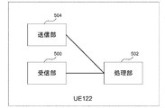
- FIG. 5 is a block diagram showing a configuration of a terminal device (UE122) according to each embodiment of the present invention. In order to avoid complicating the explanation, FIG. 5 shows only the main components closely related to one embodiment of the present invention.
- the UE 122 shown in FIG. 5 is any one of a receiving unit 500 that receives an RRC message or the like from a base station apparatus, various information elements (IE: Information Elements) included in the received message, various fields, various conditions, and the like.
- IE Information Elements
- it includes a processing unit 502 that performs processing according to all the setting information, and a transmitting unit 504 that transmits an RRC message or the like to the base station apparatus.
- the above-mentioned base station apparatus may be an eNB 102 or a gNB 108.
- the processing unit 502 may include some or all of the functions of various layers (for example, physical layer, MAC layer, RLC layer, PDCP layer, RRC layer, and NAS layer). That is, the processing unit 502 may include a physical layer processing unit, a MAC layer processing unit, an RLC layer processing unit, a PDCP layer processing unit, an RRC layer processing unit, and a part or all of the NAS layer processing unit.
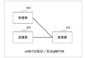
- FIG. 6 is a block diagram showing a configuration of a base station device according to each embodiment of the present invention. In order to avoid complicated explanation, FIG. 6 shows only the main components closely related to one embodiment of the present invention.
- the above-mentioned base station apparatus may be an eNB 102 or a gNB 108.
- the base station apparatus shown in FIG. 6 has a transmission unit 600 that transmits an RRC message or the like to the UE 122, and any or all of the setting information among various information elements (IE: Information Elements), various fields, various conditions, and the like. It is configured to include a processing unit 602 that causes the processing unit 502 of the UE 122 to perform processing by creating an RRC message including the RRC message and transmitting it to the UE 122, and a receiving unit 604 that receives an RRC message or the like from the UE 122.
- the processing unit 602 may include some or all of the functions of various layers (for example, physical layer, MAC layer, RLC layer, PDCP layer, RRC layer, and NAS layer). That is, the processing unit 602 may include a part or all of the physical layer processing unit, the MAC layer processing unit, the RLC layer processing unit, the PDCP layer processing unit, the RRC layer processing unit, and the NAS layer processing unit.
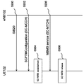
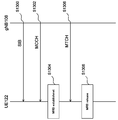
- FIG. 9 is a diagram showing a flow of procedures for setting MBMS reception using SC-PTM.
- FIG. 10 shows an ASN. Representing a field and / or an information element included in the SIB 20 (System Information Block Type 20) in FIG. It is a figure which shows an example of 1 description. Further, FIG. 11 shows an ASN. It is a figure which shows an example of 1 description.
- the processing unit 602 of the eNB 102 creates an RRC message SIB20 (System Information Block type 20), and transmits it from the transmitting unit 600 to the UE 122 via the BCCH.
- the receiving unit 500 of the UE 122 receives the SIB 20. (Step S900).
- SIB20 includes information necessary for acquiring control information (specifically, SC-MCCH) regarding transmission of MBMS using SC-PTM.
- SIB20 is a field represented by sc-mcch-ModificationPeriod indicating a period in which the contents of SC-MCCH can be changed, and sc-mcch-RepetitionPeriod indicating the transmission (retransmission) time interval of SC-MCCH in terms of the number of radio frames.
- a field represented by sc-mcch-Offset indicating the offset of the radio frame in which the SC-MCCH is scheduled, and a field represented by the sc-mcch-FirstSubframe indicating the subframe in which the SC-MCCH is scheduled.
- Fields such as sc-mcch-dration indicating the duration of the subframe in which the SC-MCCH is scheduled, and / or some or all of the information elements.
- the processing unit of the eNB 102 creates an SC-PTM setting message (SCPTM Configuration) which is an RRC message, and transmits it from the transmitting unit 600 via the SC-MCCH.
- the receiving unit 500 of the UE 122 receives the SC-PTM setting information based on the setting of the SIB 20.
- SC-RNTI Single Cell RNTI
- the SC-PTM setting information includes control information applicable to MBMS reception.
- the SC-PTM setting information is represented by a field represented by sc-mtch-InfoList containing the setting of each SC-MTCH in the cell transmitting the information, and by scptm-NightbourCellList, which is a list of adjacent cells providing MBMS. Fields, etc., and / or include some or all of the information elements.
- the sc-mtch-InfoList includes an information element represented by one or more SC-MTCH-Info.
- Each SC-MTCH-Info is an RNTI (Radio Network Temporary Identifier) that identifies a field represented by mbmsSessionInfo, which is MBMS session information, and a multicast group (specifically, SC-MTCH addressed to a specific group).
- RNTI Radio Network Temporary Identifier
- -Field represented by RNTI field represented by sc-mtch-schedulingInfo, which is DRX information for SC-MTCH
- sc-mtch which is information on neighboring cells that the MBMS session can receive using SC-MTCH.
- the mbmsSessionInfo is an identifier that identifies the MBMS bearer service described in Non-Patent Document 15 and the like, a field represented by tmgi that is TMGI (Temporary Mobile Group Identity), and an identifier of the MBMS session described in Non-Patent Document 15 and the like. Includes some or all of the fields such as the field represented by sessionId which is.
- the processing unit 502 of the UE 122 establishes an SC-MRB (Single Cell MBMS Point to Multipoint Radio Bearer), which is a wireless bearer for receiving an MBMS session using an SC-PTM in order to start receiving an MBMS session of interest.
- the process may be performed (step S904).
- the SC-MRB establishment process is performed, for example, at the start of the MBMS session, when the MBMS service of interest enters the cell provided via the SC-MRB, or when the UE 122 becomes interested in the MBMS service. It may be activated when the limit of the UE capability in which the reception of is suppressed is removed.
- the SC-MRB establishment process may be performed when the UE 122 is in the RRC_IDLE state, or may be performed when the UE 122 is in the RRC_CONNECTED state.
- the processing unit 502 of the UE 122 may perform a part or all of the following processes (A) to (D).
- the physical layer is set based on the sc-mtch-InfoList described above.
- D Notify the upper layer of the establishment of SC-MRB by notifying the tmgi and sessionId corresponding to the established SC-MRB.
- the processing unit 502 of the UE 122 receives the MBMS session via the established SC-MRB according to the SC-PTM setting message described above (step S906). Prior to receiving the MBMS session, the processing unit 502 of the UE 122 notifies the eNB 102 that it receives the MBMS service via the SC-MRB or is interested in receiving the MBMS service. (MBMS Session Indication) may be created and transmitted from the transmission unit 504 to the eNB 102 (not shown). The MBMS interest notification message may include information on whether or not the MBMS service reception is prioritized over the unicast reception.
- the MBMS interest notification message may be sent at the time of transitioning to the RRC_CONNECTED state after receiving the SIB20, or after transitioning to the RRC_CONCEPTED state. Further, the MBMS interest notification message may be sent when SIB20 is received at the time of handover, or may be sent when SIB20 is received at the time of reestablishing the RRC connection.
- the processing unit 502 of the UE 122 may perform the SC-MRB release process in order to stop the reception of the MBMS session (step S908).
- the SC-MRB release process is performed, for example, when the receiving MBMS session is stopped, when the SC-MRB leaves the established cell, when the interest in the MBMS service is lost, or when the MBMS service is limited in UE capability. It may be started when reception is suppressed.
- the SC-MRB release process may be performed when the UE 122 is in the RRC_IDLE state, or may be performed when the UE 122 is in the RRC_CONNECTED state.
- the processing unit 502 of the UE 122 may perform a part or all of the following processes (A) to (B).
- Non-Patent Document 4 In addition to MBMS transmission / reception in the terminal device from the base station device using SC-PTM (hereinafter referred to as MBMS transmission / reception), MBMS transmission / reception using MBSFN Is also standardized. However, for MBMS transmission / reception using SC-PTM and MBMS transmission / reception using MBSFN described in Non-Patent Document 4, E-UTRA is used as the RAT. Multicast broadcast service (MBS: Multicast Broadcast Service) transmission / reception using NR as RAT is also not standardized.
- MBS Multicast Broadcast Service
- MBS, MBS service, and MBS session used in the embodiments of the present invention may have the same meaning or may be paraphrased with each other. Further, the terms MBS, MBS service, and MBS session used in the embodiment of the present invention may have the same meanings as the MBMS, MBMS service, and MBMS session described in Non-Patent Document 4 and the like. good.
- the MRB may be a radio bearer established in the UE 122 for MBS reception. Further, the MRB may be a wireless bearer established in gNB 108 for MBS transmission.
- FIG. 12 is a diagram showing an example showing the configuration of the SDAP sublayer according to the embodiment of the present invention.
- FIG. 12A shows an example in which RLC-SAP (RLC-Service Access Point) exists between the SDAP sublayer and the RLC sublayer.
- RLC-SAP RLC-Service Access Point
- the MBS session data received via the MRB in the UE 122 may be passed to the SDAP entity as the RLC SDU in the RLC entity of the MRB described above.
- the MBS session data sent from the core network is the QoS flow to which the above-mentioned MBS session data is linked in the PDU entity of the gNB 108, and the MRB. It may be submitted as SDAP PDU to the RLC entity of MRB that is associated and associated.
- FIG. 12 is an example in which PDCP-SAP (PDCP-Service Access Point) exists between the SDAP sublayer and the PDCP sublayer.
- the MBS session data received via the MRB in the UE 122 may be passed to the PDCP entity of the MRB as the RLC SDU in the RLC entity of the MRB described above.
- the PDCP entity to which the above-mentioned RLC SDU is delivered may be delivered to the SDAP entity as a PDCP SDU as it is without performing any processing on the delivered RLC SDU, that is, the PDCP PDU. Further, in the example of FIG.
- the MBS session data sent from the core network is the QoS flow to which the above-mentioned MBS session data is associated with the SDAP entity of the gNB 108, and the MRB. It may be submitted as SDAP PDU to the PDCP entity of MRB that is associated and associated.
- the PDCP entity to which the above-mentioned SDAP PDU is delivered may be delivered to the above-mentioned MRB RLC entity as a PDCP PDU as it is without performing any processing on the delivered SDAP PDU, that is, PDCP SDU. That is, in the example of FIG. 12B, the PDCP entity may exist as a transparent entity that does not perform any processing. Further, in the example of FIG. 12B, the PDCP entity may exist as an entity that performs a part of processing of the PDCP sublayer.
- being linked may be paraphrased as being bundled, or may be paraphrased as another similar term.
- associating may be paraphrased as a map, or may be paraphrased as another similar term.
- the SDAP entity with which the MRB is associated may be associated with one or more DRBs. That is, the SDAP entity may be established and / or set in common with the MBS service and the unicast service. Further, one PDU session may correspond to the MBS service and the unicast service, and may provide the MBS service and / or the unicast service. Further, one SDAP entity common to the MBS service and the unicast service may be established and / or set for one PDU session. Further, the SDAP entity to which the MRB is associated is for the MBS service, and the DRB for the unicast service does not have to be associated.
- one SDAP entity for MBS service (for MRB) and one SDAP entity for unicast service (for DRB) may be established and / or set for one PDU session, respectively.
- the PDU session for the MBS service may exist separately from the PDU session for the unicast service.
- one SDAP entity for MBS service may be established and / or set for the PDU session for MBS service.
- the SDAP entity does not have to be established and / or set in the PDU session for the MBS service.
- at least one MRB and / or at least one DRB may be established in the PDU session.
- the SDAP entity to which the MRB is associated may be established and / or set when the UE 122 transitions from the RRC_IDLE state and / or the RRC_INACTIVE state to the RRC_CONNECTED state. Also, the SDAP entity with which the MRB is associated may be established and / or set when the UE 122 is in the RRC_INACIVE state and / or the RRC_CONNECTED state.
- FIG. 13 is a diagram showing an example of a flow of procedures for setting MBS reception in NR in the embodiment of the present invention.
- the parameter is ASN. It may be the field in 1 and / or the information element.
- the processing unit 602 of the gNB 108 creates an SIB (System Information Block), which is one of the RRC messages, in order to broadcast the information necessary for acquiring the control information related to the MBS transmission, and the transmitting unit. It may be transmitted from 600 to UE 122.
- the receiving unit 500 of the UE 122 receives the above-mentioned SIB. (Step S900).
- the SIB described above may be transmitted via the BCCH logical channel.
- the information necessary for acquiring the control information related to the MBS transmission described above may be information related to the MCCH (Multicast Control Channel) logical channel.
- MCCH Multicast Control Channel
- the MCCH described above may be a point-to-multipoint downlink channel for sending MBS control information for one or more MTCH (Multicast Traffic Channel) logical channels from the gNB 108 to the UE 122. good. Further, the MTCH described above may be a one-to-multipoint downlink channel for transmitting MBS data from the gNB 108 to the UE 122. The MTCH described above may be used by the UE 122 only if it receives the MBMS. The above-mentioned MCCH may be referred to by another name such as MBS-MCCH, NR-MCCH, and the like.
- the above-mentioned MTCH may be called by another name such as MBS-MTCH, NR-MTCH and the like. Further, MBS transmission may be performed via MRB. Further, the above-mentioned MCCH may be mapped to an MCH (Multicast Channel) which is a downlink transport channel, or may be mapped to a DL-SCH (Downlink Shared Channel) which is a downlink transport channel. Further, the above-mentioned MTCH may be mapped to an MCH (Multicast Channel) which is a downlink transport channel, or may be mapped to a DL-SCH (Downlink Shared Channel) which is a downlink transport channel.
- MCH Multicast Channel
- DL-SCH Downlink Shared Channel
- the SIB described above includes, for example, a parameter indicating a period in which the contents of the MCCH can be changed, a parameter relating to the transmission (retransmission) time interval of the MCCH, a parameter indicating the offset of the radio frame in which the MCCH is scheduled, and a sub in which the MCCH is scheduled. It may include some or all of the parameters such as a parameter indicating a frame, a parameter indicating the period of the subframe in which the MCCH is scheduled, and the like.
- the parameter related to the transmission (retransmission) time interval of the MCCH described above may be indicated by the number of radio frames.
- the processing unit of gNB 108 may create an RRC message transmitted by the above-mentioned MCCH and transmit it from the transmission unit 600.
- the receiving unit 500 of the UE 122 may receive the RRC message transmitted by the above-mentioned MCCH based on the above-mentioned SIB setting.
- a dedicated RNTI Radio Network Temporary Identifier
- the RRC message transmitted by the MCCH described above will be described using the message name MBS setting information message, but may be another message name.
- the above-mentioned MBS setting information may include control information applicable to MBS reception.
- the MBS configuration information includes parameters related to MBS session information, parameters indicating RNTI that identifies a multicast group (MTCH addressed to a specific group), parameters related to DRX information for MTCH, and a list of adjacent cells that provide the same MBS. It may include some or all of the fields such as the parameters shown.
- the parameters related to the MBS session information described above include, for example, a parameter indicating TMGI (Temporary Mobile Group Identity) described in Non-Patent Document 15, which is an identifier that identifies an MBS (or MBMS) bearer service, and an MBS (or MBMS) session.
- TMGI Temporal Mobile Group Identity
- a parameter indicating the Session ID described in Non-Patent Document 15 or the like which is an identifier, the above-mentioned MBS (or MBMS) bearer service, and / or a parameter indicating the PDU session to which the above-mentioned MBS session belongs, the above-mentioned MBS (or MBMS) bearer. It may include some or all of the parameters such as the service and / or the parameters indicating the QoS flow used in the MBS session described above.
- the parameters included in the above-mentioned MBS setting information may be included in a plurality in the form of a list.
- the parameters included in the form of the above list may be present for each MTCH (or each MBS service) in the cell to which the above MCCH is sent.
- the above-mentioned parameter indicating the list of adjacent cells providing the same MBS may include a parameter indicating the list of adjacent cells providing the same MBS via MTCH and / or MRB, and may be the same. May include parameters indicating a list of adjacent cells that provide the MBS of unicast and / or DTCH and / or DRB.
- the parameter indicating the above-mentioned PDU session may be the PDU session ID described in Non-Patent Document 2 and the like. Further, the above-mentioned parameters indicating the PDU session and / or the parameters indicating the QoS flow may be included in the parameters indicating the SDAP setting.
- the processing unit 502 of the UE 122 may perform an MRB establishment process in order to start receiving the MBS session of interest (step S1304).
- MRB establishment process for example, at the start of the MBS session, when the UE 122 enters a cell provided via the MRB for the MBS service of interest, or when the MBS service becomes interested, reception of the MBS service is suppressed. It may be activated when the limit of UE capability that has been set is removed.
- the MRB establishment process may be performed when the UE 122 is in the RRC_IDLE state, may be performed when the UE 122 is in the RRC_INACTIVE state, or may be performed when the UE 122 is in the RRC_CONNECTED state.
- the processing unit 502 of the UE 122 may perform a part or all of the following processes (A) to (G).
- the process (A) may be performed when the UE 122 is in the RRC_CONNECTED state and / or the RRC_INACIVE state.
- the process (F) may be performed when the UE 122 is in the RRC_CONCEPTED state, or may be performed when the UE 122 is in the RRC_CONNECTED state and / or the RRC_INACTIVE state. Further, the process (F) may be performed when the UE 122 transitions from the RRC_IDLE state and / or the RRC_INACTIVE state to the RRC_CONNECTED state.
- the SDAP entity If the SDAP entity does not exist in the PDU session corresponding to the parameter indicating the PDU session included in the MBS setting, the SDAP entity is established and / or set.
- B Establish a PDCP entity according to the default settings for establishing MRB.
- C Establish an RLC entity according to the default settings for establishing MRB.
- D Set the MTCH logical channel to be applied to the MRB to be established, and instruct the MAC entity so that the MBS session to be received can receive it.
- the MRB to be established is set based on the above-mentioned MBS setting that received the physical layer.
- (F) Associate the SDAP entity with the established MRB.
- G Notify the establishment of MRB by notifying the upper layer of information including a part or all of TMGI, Session ID, PDU session ID, and QoS flow corresponding to the established MRB.
- the processing unit 502 of the UE 122 receives the MBS session via the established MRB according to the above-mentioned PTM setting message (step S1306).
- the processing unit 502 of the UE 122 Prior to receiving the MBS session, the processing unit 502 of the UE 122 creates and transmits an RRC message for notifying the gNB 108 that it receives the MBS service via the MRB or is interested in receiving it. It may be transmitted from unit 504 to eNB 102 (not shown).
- the MBS Interest Notification message (MBSInterestIndication) is the above-mentioned RRC message for notifying the gNB 108 of receiving the MBS service via MRB or being interested in receiving the MBS service.
- the MBS interest notification message may include information on whether or not the MBS service reception is prioritized over other unicast receptions. Also, in the MBS interest notification message, the MBS service cannot be received via MTCH and / or MRB from a cell that can receive the MBS service via MTCH and / or MRB, but the same MBS service cannot be received via MTCH and / or MRB. / Or when moved to a cell that can be received via the DRB, it may include information on whether or not the same MBS service is received via the DTCH and / or the DRB.
- the MBS interest notification message may be sent at the time of transitioning to the RRC_CONNECTED state after receiving the SIB described in step S1300, or after transitioning to the RRC_CONNECTED state. Further, the MBS interest notification message may be sent when the SIB described in step S1300 is received at the time of handover, or is sent when the SIB described in step S1300 is received at the time of reestablishing the RRC connection. It may be sent when the SIB described in step S1300 is received at the time of transition from the RRC_INACTIVE state to the RRC_CONNECTED state.
- the processing unit 502 of the UE 122 may perform an MRB release process in order to stop the reception of the MBMS session (step S1308).
- the MRB release process lost interest in the MBS service, for example, when stopping the receiving MBS session, leaving the cell where the MRB was established, or leaving the cell where the MBS service could be received using the MRB. At that time, it may be started when the reception of the MBS service is suppressed due to the limit of the UE capability.
- the MRB release process may be performed when the UE 122 is in the RRC_IDLE state, may be performed when the UE 122 is in the RRC_INACTIVE state, or may be performed when the UE 122 is in the RRC_CONNECTED state.
- the processing unit 502 of the UE 122 may perform a part or all of the following processes (A) to (D).
- the following process (D) may be performed only when the UE 122 is in the RRC_CONNECTED state and / or the RRC_INACTIVE state.
- A The PDCP entity of the MRB to be released is released.
- B Release the MRB RLC entity to be released, and the associated MAC and physical layer settings.
- C Notify the release of the MRB by notifying the upper layer of information including a part or all of the TMGI, Session ID, PDU session ID, and QoS flow corresponding to the released MRB.
- D Among the SDAP entities, the SDAP entity is released to the associated MRB and / or the SDAP entity that does not have the DRB.
- the processing unit 502 of the UE 122 is established when the SDAP entity for the PDU session corresponding to the field indicated by pdu-cession included in the above-mentioned message regarding the resetting of the RRC connection exists.
- the upper layer is notified that the user plane resource for the PDU session described above has been established. You may. It should be noted that when there is an SDAP entity for the PDU session corresponding to the field indicated by the above-mentioned "pdu-cession, and the established or established DRB is the above-mentioned SDAP entity and / or the above-mentioned PDU session.
- the SDAP entity described above is the SDAP entity established at the time of MRB establishment, and the SDAP entity described above and / or the first DRB for the PDU session described above is established. Or it may be established.
- the SDAP entity that does not have the associated DRB may notify the higher layer that the user plane resource for the SDAP entity that does not have the associated DRB described above has been released based on the existence of.
- the UE 122 after the UE 122 receives the message regarding the resetting of the RRC connection and performs the process related to the setting of the wireless bearer, the associated DRB and / or MRB among the SDAP entities Based on the existence of an SDAP entity that does not have, the SDAP entity that does not have the associated DRB and / or MRB described above may be released.
- the UE 122 can efficiently receive the MBS by using the NR.
- the wireless bearers in the above description may be DRBs, SRBs, DRBs and SRBs, respectively.
- A may be paraphrased as B
- B may include the meaning of paraphrasing B as A in addition to paraphrasing A as B.
- C may be D
- C C may be E
- D may be E
- F may be G
- G G may be H
- F H
- condition "A” and the condition "B” are contradictory conditions
- condition “B” may be expressed as the “other” condition of the condition "A”. good.
- a uniform embodiment of the present invention is a terminal device that communicates with a base station device, and is a receiving unit that receives an RRC message including setting information of a multicast / broadcast service (MBS) from the base station device.
- the MBS setting information includes MBS session information
- the MBS session information includes PDU session information
- the processing unit includes the terminal device to start receiving the MBS session. Based on the above, a wireless bearer for MBS is established, and a process of notifying a part or all of the MBS session information to the upper layer is performed.
- the processing unit further performs a process of establishing the SDAP entity if the SDAP entity for the PDU session does not exist, based on the terminal device starting receiving the MBS session.
- the terminal device according to 1).
- the establishment of the radio bearer for MBS includes the establishment of a PDCP entity, the establishment of an RLC entity, and the setting of a logical channel, and some or all of the setting of a physical layer, (1) or (2).
- the embodiment of the present invention is a method of a terminal device that communicates with a base station device, and receives an RRC message including setting information of a multicast broadcast service (MBS) from the base station device.
- the MBS setting information includes MBS session information
- the MBS session information includes PDU session information
- the terminal device establishes a wireless bearer for MBS based on starting reception of the MBS session. , Notify a part or all of the MBS session information to the upper layer.
- the method of the terminal device further establishes the SDAP entity if the SDAP entity for the PDU session does not exist, based on the terminal device starting to receive the MBS session (4). ).
- the establishment of the radio bearer for MBS includes the establishment of a PDCP entity, the establishment of an RLC entity, and the setting of a logical channel, and some or all of the setting of a physical layer, (4) or (5).
- a program operating on a device controls a Central Processing Unit (CPU) or the like to operate a computer so as to realize the functions of the above-described embodiment related to one aspect of the present invention. It may be a program.
- the program or the information handled by the program is temporarily read into volatile memory such as Random Access Memory (RAM) at the time of processing, or stored in non-volatile memory such as flash memory or Hard Disk Drive (HDD), and is required.
- RAM Random Access Memory
- HDD Hard Disk Drive
- a part of the device according to the above-described embodiment may be realized by a computer.
- the program for realizing this control function is recorded on a recording medium that can be read by the computer, and the program recorded on the recording medium is read by the computer system and executed. May be good.
- the "computer system” referred to here is a computer system built into the device, and includes hardware such as an operating system and peripheral devices.
- the "recording medium that can be read by a computer” may be any of a semiconductor recording medium, an optical recording medium, a magnetic recording medium, and the like.
- a "recording medium that can be read by a computer” is a communication line that dynamically holds a program for a short time, like a communication line when a program is transmitted via a network such as the Internet or a communication line such as a telephone line. It may also include a program that holds a program for a certain period of time, such as a volatile memory inside a computer system that serves as a server or a client in that case. Further, the above program may be for realizing a part of the above-mentioned functions, and may be further realized by combining the above-mentioned functions with a program already recorded in the computer system. ..
- each functional block or feature of the device used in the above-described embodiment can be implemented or executed in an electric circuit, that is, typically an integrated circuit or a plurality of integrated circuits.
- Electrical circuits designed to perform the functions described herein are general purpose processors, digital signal processors (DSPs), application specific integrated circuits (ASICs), field programmable gate arrays (FPGAs), or others. Programmable logic devices, discrete gate or transistor logic, discrete hardware components, or a combination thereof.
- the general purpose processor may be a microprocessor, or instead the processor may be a conventional processor, controller, microprocessor, or state machine.
- the general-purpose processor or each of the above-mentioned circuits may be composed of a digital circuit or an analog circuit.
- an integrated circuit technology that replaces the current integrated circuit appears due to advances in semiconductor technology, it is also possible to use an integrated circuit based on this technology.
- the invention of the present application is not limited to the above-described embodiment.
- an example of the device has been described, but the present invention is not limited to this, and the present invention is not limited to this, and is a stationary or non-movable electronic device installed indoors or outdoors, for example, an AV device, a kitchen device, and the like. It can be applied to terminal devices or communication devices such as cleaning / washing equipment, air conditioning equipment, office equipment, vending machines, and other living equipment.
- the embodiment of the present invention has been described in detail with reference to the drawings, but the specific configuration is not limited to this embodiment, and includes design changes and the like within a range that does not deviate from the gist of the present invention.
- one aspect of the present invention can be variously modified within the scope of the claims, and the technical aspects of the present invention can also be obtained by appropriately combining the technical means disclosed in the different embodiments. Included in the range.
- the elements described in the above-described embodiment include a configuration in which elements having the same effect are replaced with each other.
- One aspect of the present invention is used, for example, in a communication system, a communication device (for example, a mobile phone device, a base station device, a wireless LAN device, or a sensor device), an integrated circuit (for example, a communication chip), a program, or the like. be able to.
- a communication device for example, a mobile phone device, a base station device, a wireless LAN device, or a sensor device
- an integrated circuit for example, a communication chip
- a program or the like.
- E-UTRA 102 eNB 104 EPC 106 NR 108 gNB 110 5GC 112, 114, 116, 118, 120, 124 Interface 122 UE 200, 300 PHY 202, 302 MAC 204, 304 RLC 206, 306 PDCP 208, 308 RRC 310 SDAP 210, 312 NAS 500,604 Receiver 502,602 Processing 504,600 Transmitter
Landscapes
- Engineering & Computer Science (AREA)
- Computer Networks & Wireless Communication (AREA)
- Signal Processing (AREA)
- Multimedia (AREA)
- Mobile Radio Communication Systems (AREA)
Abstract
This terminal device comprises: a reception unit for receiving an RRC message from a base station, the RRC message including MBS setting information; and a processing unit. The MBS setting information includes MBS session information. The MBS session information includes PDU session information. The processing unit performs processing for establishing a wireless bearer for MBS on the basis of initiation of the MBS session reception, and for notifying an upper layer of part or all of the MBS session information.
Description
本発明は、端末装置、方法、および、集積回路に関する。
本願は、2020年4月28日に日本に出願された特願2020-79034号について優先権を主張し、その内容をここに援用する。 The present invention relates to terminal devices, methods, and integrated circuits.
The present application claims priority with respect to Japanese Patent Application No. 2020-79034 filed in Japan on April 28, 2020, the contents of which are incorporated herein by reference.
セルラ移動通信システムの標準化プロジェクトである、第3世代パートナーシッププロジェクト(3rd Generation Partnership Project:3GPP)において、無線アクセス、コアネットワーク、サービス等を含む、セルラ移動通信システムの技術検討及び規格策定が行われている。
In the 3rd Generation Partnership Project (3GPP), which is a standardization project for cellular mobile communication systems, technical studies and standardization of cellular mobile communication systems, including wireless access, core networks, and services, have been carried out. There is.
例えば、E-UTRA(Evolved Universal Terrestrial Radio Access)は、3GPPにおいて、第3.9世代および第4世代向けセルラ移動通信システム向け無線アクセス技術(Radio Access Technology:RAT)として、技術検討及び規格策定が開始された。現在も3GPPにおいて、E-UTRAの拡張技術の技術検討及び規格策定が行われている。なお、E-UTRAは、Long Term Evolution(LTE:登録商標)とも称し、拡張技術をLTE-Advanced(LTE-A)、LTE-Advanced Pro(LTE-A Pro)と称する事もある。
For example, E-UTRA (Evolved Universal Terrestrial Radio Access) has been developed as a radio access technology (Radio Access Technology: RAT) for 3.9G and 4th generation cellular mobile communication systems in 3GPP. It was started. Currently, 3GPP is conducting technical studies and standardization of E-UTRA extended technology. In addition, E-UTRA is also referred to as Long Term Evolution (LTE: registered trademark), and the extended technology may be referred to as LTE-Advanced (LTE-A) or LTE-Advanced Pro (LTE-A Pro).
また、NR(New Radio、またはNR Radio access)は、3GPPにおいて、第5世代(5th Generation:5G)向けセルラ移動通信システム向け無線アクセス技術(Radio Access Technology:RAT)として、技術検討及び規格策定が開始された。現在も3GPPにおいて、NRの拡張技術の技術検討及び規格策定が行われている。
In addition, NR (New Radio or NR Radio access) has been studied and standardized as a radio access technology (Radio Access Technology: RAT) for cellular mobile communication systems for the 5th generation (5th Generation: 5G) in 3GPP. It was started. Currently, 3GPP is conducting technical studies and standardization of NR extension technology.
E-UTRAの拡張技術検討の一つとして、マルチキャスト/ブロードキャストサービスを提供するために、MBMS(Multimedia Broadcast Multicast Service)伝送技術が規格化されている。MBMS伝送には、MBSFN(Multicast Broadcast Single Frequency Network)又はSC-PTM(Single Cell Point-To-Multipoint)を用いた伝送が用いられる。
MBMS (Multicast Broadcast Multicast Service) transmission technology has been standardized in order to provide a multicast / broadcast service as one of the studies on the extended technology of E-UTRA. For MBMS transmission, transmission using MBSFN (Multicast Broadcast Single Frequency Network) or SC-PTM (Single Cell Point-To-Multipoint) is used.
MBSFNを用いた伝送は、複数のセルからなるMBSFN(Multicast-Broadcast Single-Frequency Network)エリア単位で、PMCH(Physical Multicast Channel)を用いて、マルチキャスト/ブロードキャストデータの送信を行う。これに対し、SC-PTMを用いた伝送は、セル単位で、PDSCH(Physical Downlink Shared Channel)を用いて、マルチキャストデータの送信を行う。
For transmission using MBSFN, multicast / broadcast data is transmitted using PMCH (Physical Multicast Channel) in units of MBSFN (Multicast-Broadcast Single-Freequency Network) area consisting of a plurality of cells. On the other hand, in the transmission using SC-PTM, multicast data is transmitted using PDSCH (Physical Downlink Shared Channel) on a cell-by-cell basis.
一方、NRの拡張技術としての、マルチキャスト/ブロードキャストサービス(Multicast Broadcast Service:MBS)が検討されている。(非特許文献1)。NRを介してMBSを行う場合、E-UTRAとは異なるNR特有技術や、5G向けに規格策定されたコアネットワーク等を考慮する必要がある。しかしNRを用いて効率的にMBSを受信するための詳細な動作については、まだ検討がなされていない。
On the other hand, a multicast / broadcast service (Multicast Broadcast Service: MBS) as an extension technology of NR is being studied. (Non-Patent Document 1). When MBS is performed via NR, it is necessary to consider NR-specific technology different from E-UTRA, core network standardized for 5G, and the like. However, the detailed operation for efficiently receiving MBS using NR has not yet been studied.
本発明の一態様は、上記した事情に鑑みてなされたもので、NRを用いて効率的にMBSを受信することができる端末装置、方法、集積回路を提供することを目的の一つとする。
One aspect of the present invention has been made in view of the above circumstances, and one of the objects is to provide a terminal device, a method, and an integrated circuit capable of efficiently receiving MBS using NR.
上記の目的を達成するために、本発明の一態様は、以下のような手段を講じた。すなわち本発明の一態様は、基地局装置と通信する端末装置であって、前記基地局装置からマルチキャスト・ブロードキャストサービス(MBS)の設定情報を含む、RRCメッセージを受信する受信部と、処理部と、を備え、前記MBSの設定情報は、MBSセッション情報を含み、前記MBSセッション情報は、PDUセッション情報を含み、前記処理部は、前記端末装置が、前記MBSセッションの受信を開始する事に基づいて、MBS用無線ベアラを確立し、前記MBSセッション情報の一部又は全てを上位レイヤに通知する処理を行う。
In order to achieve the above object, one aspect of the present invention has taken the following measures. That is, one aspect of the present invention is a terminal device that communicates with a base station device, and includes a receiving unit and a processing unit that receive an RRC message including setting information of a multicast broadcast service (MBS) from the base station device. The MBS setting information includes MBS session information, the MBS session information includes PDU session information, and the processing unit is based on the terminal device starting receiving the MBS session. Therefore, a wireless bearer for MBS is established, and a process of notifying a part or all of the MBS session information to the upper layer is performed.
また本発明の一態様は、基地局装置と通信する端末装置の方法であって、前記基地局装置からマルチキャスト・ブロードキャストサービス(MBS)の設定情報を含む、RRCメッセージを受信し、前記MBSの設定情報は、MBSセッション情報を含み、前記MBSセッション情報は、PDUセッション情報を含み、前記端末装置が、前記MBSセッションの受信を開始する事に基づいて、MBS用無線ベアラを確立し、前記MBSセッション情報の一部又は全てを上位レイヤに通知する。
Further, one aspect of the present invention is a method of a terminal device that communicates with a base station device, in which an RRC message including setting information of a multicast broadcast service (MBS) is received from the base station device and the MBS is set. The information includes MBS session information, the MBS session information includes PDU session information, and the terminal device establishes a wireless bearer for MBS based on starting reception of the MBS session, and the MBS session. Notify the upper layer of some or all of the information.
なお、これらの包括的または具体的な態様は、システム、装置、方法、集積回路、コンピュータプログラム、または、記録媒体で実現されてもよく、システム、装置、方法、集積回路、コンピュータプログラムおよび記録媒体の任意な組み合わせで実現されてもよい。
It should be noted that these comprehensive or specific embodiments may be realized in a system, device, method, integrated circuit, computer program, or recording medium, and the system, device, method, integrated circuit, computer program, and recording medium. It may be realized by any combination of.
本発明の一態様によれば、端末装置は、NRを用いて効率的にMBSを受信することができる。
According to one aspect of the present invention, the terminal device can efficiently receive MBS using NR.
以下、本発明の実施の形態について、図面を参照して詳細に説明する。
Hereinafter, embodiments of the present invention will be described in detail with reference to the drawings.
LTE(およびLTE-A、LTE-A Pro)とNRは、異なる無線アクセス技術(Radio Access Technology:RAT)として定義されてもよい。またNRは、LTEに含まれる技術として定義されてもよい。LTEは、NRに含まれる技術として定義されてもよい。また、NRとMulti Radio Dual connectivityで接続可能なLTEは、従来のLTEと区別されてもよい。また、コアネットワークが5GCであるLTEは、コアネットワークがEPCである従来のLTEと区別されてもよい。本実施形態はNR、LTEおよび他のRATに適用されてよい。以下の説明では、LTEおよびNRに関連する用語を用いて説明するが、本実施形態は他の用語を用いる他の技術において適用されてもよい。また本実施形態でのE-UTRAという用語は、LTEという用語に置き換えられても良いし、LTEという用語はE-UTRAという用語に置き換えられても良い。
LTE (and LTE-A, LTE-A Pro) and NR may be defined as different radio access technologies (Radio Access Technology: RAT). NR may also be defined as a technique included in LTE. LTE may be defined as a technique included in NR. In addition, LTE that can be connected to NR by Multi Radio Dual connectivity may be distinguished from conventional LTE. Further, LTE having a core network of 5GC may be distinguished from conventional LTE having a core network of EPC. This embodiment may be applied to NR, LTE and other RATs. In the following description, terms related to LTE and NR will be used, but the present embodiment may be applied in other techniques using other terms. Further, the term E-UTRA in the present embodiment may be replaced with the term LTE, and the term LTE may be replaced with the term E-UTRA.
図1は本発明の各実施の形態に係る通信システムの概略図である。
FIG. 1 is a schematic diagram of a communication system according to each embodiment of the present invention.
E-UTRA100は非特許文献3等に記載の無線アクセス技術であり、一つ又は複数の周波数帯域で構成するセルグループ(Cell Group:CG)から成る。eNB(E-UTRAN Node B)102は、E-UTRA100の基地局装置である。EPC(Evolved Packet Core)104は、非特許文献14等に記載のコア網であり、E-UTRA100用のコア網として設計された。インタフェース112はeNB102とEPC104の間のインタフェース(interface)であり、制御信号が通る制御プレーン(Control Plane:CP)と、そのユーザデータが通るユーザプレーン(User Plane:UP)が存在する。
E-UTRA100 is a wireless access technology described in Non-Patent Document 3 and the like, and is composed of a cell group (Cell Group: CG) composed of one or a plurality of frequency bands. The eNB (E-UTRAN Node B) 102 is a base station device of the E-UTRA100. The EPC (Evolved Packet Core) 104 is a core network described in Non-Patent Document 14 and the like, and was designed as a core network for the E-UTRA100. The interface 112 is an interface between the eNB 102 and the EPC 104, and has a control plane (Control Plane: CP) through which control signals pass and a user plane (User Plane: UP) through which user data passes.
NR106は非特許文献9等に記載の無線アクセス技術であり、一つ又は複数の周波数帯域で構成するセルグループ(Cell Group:CG)から成る。gNB(g Node B)108は、NR106の基地局装置である。5GC110は、非特許文献2等に記載のコア網であり、NR106用のコア網として設計されているが、5GC110に接続する機能をもつE-UTRA100用のコア網として使われても良い。以下E-UTRA100とは5GC110に接続する機能をもつE-UTRA100を含んでも良い。
NR106 is a wireless access technology described in Non-Patent Document 9 and the like, and is composed of a cell group (Cell Group: CG) composed of one or a plurality of frequency bands. gNB (g Node B) 108 is a base station device of NR106. The 5GC110 is a core network described in Non-Patent Document 2 and the like, and is designed as a core network for NR106, but may be used as a core network for E-UTRA100 having a function of connecting to the 5GC110. Hereinafter, the E-UTRA 100 may include the E-UTRA 100 having a function of connecting to the 5GC110.
インタフェース114はeNB102と5GC110の間のインタフェース、インタフェース116はgNB108と5GC110の間のインタフェース、インタフェース118はgNB108とEPC104の間のインタフェース、インタフェース120はeNB102とgNB108の間のインタフェース、インタフェース124はEPC104と5GC110間のインタフェースである。インタフェース114、インタフェース116、インタフェース118、インタフェース120、及びインタフェース124等はCPのみ、又はUPのみ、又はCP及びUP両方を通すインタフェースであっても良い。また、インタフェース114、インタフェース116、インタフェース118、インタフェース120、及びインタフェース124等は、通信事業者が提供する通信システムに応じて存在しない場合もあっても良い。
Interface 114 is an interface between eNB 102 and 5GC110, interface 116 is an interface between gNB108 and 5GC110, interface 118 is an interface between gNB108 and EPC104, interface 120 is an interface between eNB102 and gNB108, and interface 124 is an interface between EPC104 and 5GC110. The interface between. The interface 114, interface 116, interface 118, interface 120, interface 124, and the like may be CP only, UP only, or an interface that passes through both CP and UP. Further, the interface 114, the interface 116, the interface 118, the interface 120, the interface 124, and the like may not exist depending on the communication system provided by the telecommunications carrier.
UE122はE-UTRA100及びNR106の内のいずれかまたは全てに対応した端末装置である。非特許文献3、及び非特許文献9の内のいずれかまたは全てに記載の通り、UE122が、E-UTRA100及びNR106の内のいずれかまたは全てを介してコア網と接続する際、UE122と、E-UTRA100及びNR106の内のいずれかまたは全てとの間に、無線ベアラ(RB:Radio Bearer)と呼ばれる論理経路が確立される。CPに用いられる無線ベアラは、シグナリング無線ベアラ(SRB:Signaling Radio Bearer)と呼ばれ、UPに用いられる無線ベアラは、データ無線ベアラ(DRB Data Radio Bearer)と呼ばれる。各RBは、RB識別子(RB Identity,又はRB ID)が割り当てられ、一意に識別される。SRB用RB識別子は、SRB識別子(SRB Identity,又はSRB ID)と呼ばれ、DRB用RB識別子は、DRB識別子(DRB Identity,又はDRB ID)と呼ばれる。
UE 122 is a terminal device corresponding to any or all of E-UTRA100 and NR106. As described in any or all of Non-Patent Documents 3 and 9, when the UE 122 connects to the core network via any or all of the E-UTRA100 and NR106, the UE 122 and A logical path called a radio bearer (RB: Radio Bearer) is established between any or all of the E-UTRA100 and the NR106. The radio bearer used for CP is called a signaling radio bearer (SRB: Signaling Radio Bearer), and the radio bearer used for UP is called a data radio bearer (DRB Data Radio Bearer). Each RB is assigned an RB identifier (RB Identity or RB ID) and is uniquely identified. The SRB RB identifier is called an SRB identifier (SRB Identity or SRB ID), and the DRB RB identifier is called a DRB identifier (DRB Identity or DRB ID).
非特許文献3に記載の通り、UE122の接続先コア網がEPC104である場合、UE122と、E-UTRA100及びはNR106の内のいずれかまたは全てとの間に確立された各DRBは更に、EPC104内を経由する各EPS(Evolved Packet System)ベアラと一意に紐づけられる。各EPSベアラは、EPSベアラ識別子(Identity,又はID)が割り当てられ、一意に識別される。また同一のEPSベアラを通るデータは同一のQoSが保証される。
As described in Non-Patent Document 3, when the core network to which the UE 122 is connected is the EPC 104, each DRB established between the UE 122 and any or all of the E-UTRA 100 and the NR 106 is further equipped with the EPC 104. It is uniquely associated with each EPS (Evolved Patent System) bearer that passes through the inside. Each EPS bearer is assigned an EPS bearer identifier (Identity or ID) and is uniquely identified. Also, the same QoS is guaranteed for the data passing through the same EPS bearer.
非特許文献9に記載の通り、UE122の接続先コア網が5GC110である場合、UE122と、E-UTRA100及びNR106の内のいずれかまたは全てとの間に確立された一つ又は複数のDRBは更に、5GC110内に確立されるPDU(Packet Data Unit)セッションの一つに紐づけられる。各PDUセッションには、一つ又は複数のQoSフローが存在する。各DRBは、紐づけられているPDUセッション内に存在する、一つ又は複数のQoSフローと対応付け(map)されても良いし、どのQoSフローと対応づけられなくても良い。各PDUセッションは、PDUセッション識別子(Identity,又はID)で識別される。また各QoSフローは、QoSフロー識別子で識別される。また同一のQoSフローを通るデータは同一のQoSが保証される。
As described in Non-Patent Document 9, when the core network to which the UE 122 is connected is 5GC110, one or more DRBs established between the UE 122 and any or all of the E-UTRA100 and the NR106 Furthermore, it is linked to one of the PDU (Packet Data Unit) sessions established in 5GC110. There is one or more QoS flows in each PDU session. Each DRB may be associated (mapped) with one or more QoS flows existing in the associated PDU session, or may not be associated with any QoS flow. Each PDU session is identified by a PDU session identifier (Identity, or ID). Each QoS flow is identified by a QoS flow identifier. Further, the same QoS is guaranteed for the data passing through the same QoS flow.
EPC104には、PDUセッション及びQoSフローの内のいずれかまたは全ては存在せず、5GC110にはEPSベアラは存在しない。UE122がEPC104と接続している際、UE122はEPSベアラの情報を持つが、PDUセッション及びQoSフローの内のいずれかまたは全ては持たない。UE122が5GC110と接続している際、UE122はPDUセッション及びQoSフローの内のいずれかまたは全ての情報を持つが、EPSベアラの情報は持たない。
EPC104 does not have any or all of the PDU sessions and QoS flows, and 5GC110 does not have EPS bearers. When the UE 122 is connected to the EPC 104, the UE 122 has information on the EPS bearer, but not any or all of the PDU session and the QoS flow. When the UE 122 is connected to the 5GC110, the UE 122 has information on any or all of the PDU session and the QoS flow, but not the EPS bearer.
なお、以下の説明において、eNB102および/またはgNB108を単に基地局装置とも称し、UE122を単に端末装置とも称する。
In the following description, the eNB 102 and / or the gNB 108 is also simply referred to as a base station device, and the UE 122 is also simply referred to as a terminal device.
図2は本発明の各実施の形態における、E-UTRA無線アクセス層(無線アクセスレイヤ)における端末装置と基地局装置のUP及びCPのプロトコルスタック(Protocol Stack)図である。
FIG. 2 is a protocol stack (Protocol Stack) diagram of UP and CP of the terminal device and the base station device in the E-UTRA wireless access layer (radio access layer) in each embodiment of the present invention.
図2(A)はE-UTRA100においてUE122がeNB102と通信を行う際に用いるUPのプロトコルスタック図である。
FIG. 2A is a protocol stack diagram of UP used when the UE 122 communicates with the eNB 102 in the E-UTRA100.
PHY(Physical layer)200は、無線物理層(無線物理レイヤ)であり、物理チャネル(Physical Channel)を利用して上位層(上位レイヤ)に伝送サービスを提供する。PHY200は、後述する上位のMAC(Medium Access Control layer)202とトランスポートチャネル(Transport Channel)で接続される。トランスポートチャネルを介して、MAC202とPHY200の間でデ-タが移動する。UE122とeNB102のPHY間において、無線物理チャネルを介してデ-タの送受信が行われる。PHY200において、様々な制御情報を識別するために、RNTI(Radio Network Temporary Identifire)が用いられる。
The PHY (Physical layer) 200 is a wireless physical layer (radio physical layer), and provides a transmission service to an upper layer (upper layer) by using a physical channel (Physical Channel). The PHY200 is connected to a higher-level MAC (Medium Access Control layer) 202, which will be described later, by a transport channel (Transport Channel). Data moves between MAC202 and PHY200 via the transport channel. Data is transmitted and received between the UE 122 and the PHY of the eNB 102 via the radio physical channel. In PHY200, RNTI (Radio Network Temporary Identity) is used to identify various control information.
MAC202は、多様な論理チャネル(ロジカルチャネル:Logical Channel)を多様なトランスポートチャネルにマッピングを行う媒体アクセス制御層(媒体アクセス制御レイヤ)である。MAC202は、後述する上位のRLC(Radio Link Control layer)204と、論理チャネル(ロジカルチャネル)で接続される。論理チャネルは、伝送される情報の種類によって大きく分けられ、制御情報を伝送する制御チャネルとユ-ザ情報を伝送するトラフィックチャネルに分けられる。MAC202は、間欠受信(DRX:Discontinuous Reception)及び/又は(and/or)、間欠送信(DTX:Discontinuous Transmission)を行うためにPHY200の制御を行う機能、ランダムアクセス(Random Access)手順を実行する機能、送信電力の情報を通知する機能、HARQ制御を行う機能などを持つ(非特許文献7)。
MAC202 is a medium access control layer (medium access control layer) that maps various logical channels (logical channels) to various transport channels. The MAC 202 is connected to a higher-level RLC (Radio Link Control layer) 204, which will be described later, by a logical channel (logical channel). The logical channel is roughly classified according to the type of information to be transmitted, and is divided into a control channel for transmitting control information and a traffic channel for transmitting user information. The MAC202 has a function of controlling PHY200 for performing intermittent reception (DRX: Discontinuus Reception) and / or (and / or) and intermittent transmission (DTX: Discontinuus Transmission), and a function of executing a random access (Random Access) procedure. , Has a function of notifying transmission power information, a function of performing HARQ control, and the like (Non-Patent Document 7).
E-UTRAで用いられる、上りリンク(UL:Uplink)、及び/又は下りリンク(DL:Downlink)用論理チャネルについて説明する。
The logical channel for uplink (UL: Uplink) and / or downlink (DL: Downlink) used in E-UTRA will be described.
BCCH(Broadcast Control Channel)は、システム情報(SI:System Information)等の、制御情報を報知(broadcast)するための下りリンク論理チャネルであっても良い。
BCCH (Broadcast Control Channel) may be a downlink logical channel for broadcasting control information (SI: System Information) or the like.
PCCH(Paging Control Channel)は、呼び出し(Paging)メッセージを運ぶための下りリンク論理チャネルであっても良い。またPCCHは、システム情報の変更を通知するために使われても良い。
The PCCH (Paging Control Channel) may be a downlink logical channel for carrying a calling message. The PCCH may also be used to notify changes in system information.
CCCH(Common Control Channel)は、UE122とeNB102との間で制御情報を送信するための論理チャネルであっても良い。CCCHは、UE122が、後述のRRC(Radio Resource Control)接続を有しない場合に用いられても良い。またCCCHは基地局装置と複数の端末装置との間で使われても良い。
The CCCH (Common Control Channel) may be a logical channel for transmitting control information between the UE 122 and the eNB 102. CCCH may be used when the UE 122 does not have an RRC (Radio Resource Control) connection described later. CCCH may also be used between a base station device and a plurality of terminal devices.
DCCH(Dedicated Control Channel)は、UE122とeNB102との間で、1対1(point-to-point)の双方向(bi-directional)で、専用制御情報を送信するための論理チャネルであっても良い。専用制御情報とは、各端末装置専用の制御情報であっても良い。DCCHは、UE122がeNB102との間で、後述のRRC(Radio Resource Control)接続を有する場合に用いられても良い。
The DCCH (Dedicated Control Channel) is a logical channel for transmitting dedicated control information between the UE 122 and the eNB 102 in a one-to-one (point-to-point) bi-directional manner. good. The dedicated control information may be control information dedicated to each terminal device. The DCCH may be used when the UE 122 has an RRC (Radio Resource Control) connection with the eNB 102, which will be described later.
DTCH(Dedicated Traffic Channel)は、UE122とeNB102との間で、1対1(point-to-point)で、ユーザデータを送信するための論理チャネルであっても良い。
The DTCH (Dedicated Traffic Channel) may be a logical channel for transmitting user data on a one-to-one basis (point-to-point) between the UE 122 and the eNB 102.
MTCH(Multicast Traffic Channel)は、eNB102からUE122に対し、データを送信するための1対多(point-to-multipoint)の下りリンクチャネルであっても良い。SC-MTCHは、UE122がMBMSを受信する場合にのみ、該当UE122によって使われても良い。
The MTCH (Multicast Traffic Channel) may be a point-to-multipoint downlink channel for transmitting data from the eNB 102 to the UE 122. The SC-MTCH may be used by the UE 122 only when the UE 122 receives the MBMS.
MCCH(Multicast Control Channel)は、eNB102からUE122へ、一つ又は複数のMTCHに対するMBMS制御情報を送るための、1対多(point-to-multipoint)の下りリンクチャネルであっても良い。MCCHはUE122がMBMSを受信する、又はUE122がMBMSを受信する事に興味がある時にのみ、該当UE122によって使われても良い。
The MCCH (Multicast Control Channel) may be a one-to-multipoint downlink channel for sending MBMS control information for one or more MTCHs from the eNB 102 to the UE 122. The MCCH may be used by the UE 122 only when the UE 122 receives the MBMS or is interested in the UE 122 receiving the MBMS.
SC-MTCH(Single Cell Multicast Traffic Channel)は、eNB102からUE122に対し、SC-PTMを用いてデータを送信するための1対多(point-to-multipoint)の下りリンクチャネルであっても良い。SC-MTCHは、UE122がSC-PTM(Single Cell Point-To-Multipoint)を用いてMBMSを受信する場合にのみ、該当UE122によって使われても良い。
The SC-MTCH (Single Cell Multicast Traffic Channel) may be a one-to-multipoint downlink channel for transmitting data from the eNB 102 to the UE 122 using the SC-PTM. The SC-MTCH may be used by the UE 122 only when the UE 122 receives the MBMS using the SC-PTM (Single Cell Point-To-Multipoint).
SC-MCCH(Single Cell Multicast Control Channel)は、eNB102からUE122へ、一つ又は複数のSC-MTCHに対するMBMS制御情報を送るための、1対多(point-to-multipoint)の下りリンクチャネルであっても良い。SC-MCCHはUE122がSC-PTMを用いてMBMSを受信する、又はUE122がSC-PTMを用いてMBMSを受信する事に興味がある時にのみ、該当UE122によって使われても良い。
The SC-MCCH (Single Cell Multicast Control Channel) is a one-to-multipoint downlink channel for sending MBMS control information for one or more SC-MTCHs from the eNB 102 to the UE 122. You may. The SC-MCCH may be used by the UE 122 only when the UE 122 is interested in receiving the MBMS using the SC-PTM, or the UE 122 is interested in receiving the MBMS using the SC-PTM.
E-UTRAにおける上りリンクの、論理チャネルとトランスポートチャネルのマッピングについて説明する。
The mapping between the logical channel and the transport channel of the uplink in E-UTRA will be explained.
CCCHは、上りリンクトランスポートチャネルである、UL-SCH(Uplink Shared Channel)にマップされても良い。
The CCCH may be mapped to UL-SCH (Uplink Shared Channel), which is an uplink transport channel.
DCCHは、上りリンクトランスポートチャネルである、UL-SCH(Uplink Shared Channel)にマップされても良い。
The DCCH may be mapped to UL-SCH (Uplink Shared Channel), which is an uplink transport channel.
DTCHは、上りリンクトランスポートチャネルである、UL-SCH(Uplink Shared Channel)にマップされても良い。
The DTCH may be mapped to UL-SCH (Uplink Shared Channel), which is an uplink transport channel.
E-UTRAにおける下りリンクの、論理チャネルとトランスポートチャネルのマッピングについて説明する。
The mapping between the logical channel and the transport channel of the downlink in E-UTRA will be explained.
BCCHは、下りリンクトランスポートチャネルであるBCH(Broadcast Channel)、及び/又はDL-SCH(Downlink Shared Channel)にマップされても良い。
BCCH may be mapped to BCH (Broadcast Channel), which is a downlink transport channel, and / or DL-SCH (Downlink Shared Channel).
PCCHは、下りリンクトランスポートチャネルであるPCH(Paging Channel)にマップされても良い。
The PCCH may be mapped to a PCH (Paging Channel) which is a downlink transport channel.
CCCHは、下りリンクトランスポートチャネルであるDL-SCH(Downlink Shared Channel)にマップされても良い。
The CCCH may be mapped to the DL-SCH (Downlink Shared Channel), which is a downlink transport channel.
DCCHは、下りリンクトランスポートチャネルであるDL-SCH(Downlink Shared Channel)にマップされても良い。
The DCCH may be mapped to the DL-SCH (Downlink Shared Channel), which is a downlink transport channel.
DTCHは、下りリンクトランスポートチャネルであるDL-SCH(Downlink Shared Channel)にマップされても良い。
The DTCH may be mapped to the DL-SCH (Downlink Shared Channel), which is a downlink transport channel.
MTCHは、下りリンクトランスポートチャネルであるMCH(Multicast Channel)にマップされても良い。
MTCH may be mapped to MCH (Multicast Channel) which is a downlink transport channel.
MCCHは、下りリンクトランスポートチャネルであるMCH(Multicast Channel)にマップされても良い。
The MCCH may be mapped to the MCH (Multicast Channel), which is a downlink transport channel.
SC-MTCHは、下りリンクトランスポートチャネルであるDL-SCH(Downlink Shared Channel)にマップされても良い。
The SC-MTCH may be mapped to the DL-SCH (Downlink Shared Channel), which is a downlink transport channel.
SC-MTCHは、下りリンクトランスポートチャネルであるDL-SCH(Downlink Shared Channel)にマップされても良い。
The SC-MTCH may be mapped to the DL-SCH (Downlink Shared Channel), which is a downlink transport channel.
RLC204は、後述する上位のPDCP(Packet Data Convergence Protocol Layer)206から受信したデ-タを分割(Segmentation)し、下位層(下位レイヤ)が適切にデ-タ送信できるようにデ-タサイズを調節する無線リンク制御層(無線リンク制御レイヤ)である。RLC204には、トランスパレントモード(TM:Transparent Mode)、非応答モード(UM:Unacknowledged Mode)、応答モード(AM:Acknowledged Mode)の3つのモードがある。TMでは上位層から受信したデータの分割は行わず、RLCヘッダの付加は行わない。UMでは上位層から受信したデータの分割、及びRLCヘッダの付加等は行うが、データの再送制御は行わない。AMでは上位層から受信したデータの分割、及びRLCヘッダの付加、データの再送制御等を行う。再送制御機能は各デ-タが要求するQoS(Quality of Service)を保証するための機能であっても良い。データの再送制御を行うにあたり、RLCの受信側から送信側に送られる、届いていないデータの情報の事を、ステータスレポートと言う。またRLCの送信側から受信側に送られる、ステータスレポートを促す指示の事をポール(poll)と言う。なお、TMで下位層に送信されるデータの事をTMD PDU、UMで下位層に送信されるデータの事をUMD PDU、AMで下位層に送信されるデータの事をAMD PDUと呼ぶ場合がある。(非特許文献6)。
The RLC204 divides the data received from the upper PDCP (Packet Data Convergence Protocol Layer) 206, which will be described later, and adjusts the data size so that the lower layer (lower layer) can appropriately transmit the data. It is a wireless link control layer (wireless link control layer). The RLC204 has three modes: a transparent mode (TM: Transparent Mode), a non-response mode (UM: Unlockedged Mode), and a response mode (AM: Acknowledged Mode). The TM does not divide the data received from the upper layer and does not add the RLC header. The UM divides the data received from the upper layer, adds the RLC header, and the like, but does not control the retransmission of the data. The AM divides the data received from the upper layer, adds the RLC header, controls the retransmission of the data, and the like. The retransmission control function may be a function for guaranteeing the QoS (Quality of Service) required by each data. Information on undelivered data sent from the receiving side of RLC to the transmitting side when controlling data retransmission is called a status report. In addition, the instruction sent from the transmitting side of RLC to the receiving side to prompt the status report is called a poll. The data transmitted to the lower layer by TM may be referred to as TMD PDU, the data transmitted to the lower layer by UM may be referred to as UMD PDU, and the data transmitted to the lower layer by AM may be referred to as AMD PDU. be. (Non-Patent Document 6).
PDCP206は、IPパケット(IP Packet)等のユーザデータを無線区間で効率的に伝送するためのパケットデータ収束プロトコル層(パケットデータ収束プロトコルレイヤ)である。PDCP206は、不要な制御情報の圧縮を行うヘッダ圧縮機能を持ってもよい。また、PDCP206は、デ-タの暗号化の機能も持ってもよい。またPDCP206は、リオーダリング(re-ordering)の機能を持っても良い(非特許文献5)。
PDCP206 is a packet data convergence protocol layer (packet data convergence protocol layer) for efficiently transmitting user data such as an IP packet (IP Packet) in a wireless section. The PDCP206 may have a header compression function that compresses unnecessary control information. The PDCP206 may also have a data encryption function. Further, PDCP206 may have a function of reordering (Non-Patent Document 5).
なお、MAC202、RLC204、PDCP206において処理されたデータの事を、それぞれMAC PDU(Protocol Data Unit)、RLC PDU、PDCP PDUと呼ぶ。また、MAC202、RLC204、PDCP206に上位層から渡されるデータ、又は上位層に渡すデータの事を、それぞれMAC SDU(Service Data Unit)、RLC SDU、PDCP SDUと呼ぶ。また分割されたRLC SDUの事をRLC SDUセグメントと呼ぶ。
The data processed by MAC202, RLC204, and PDCP206 are called MAC PDU (Protocol Data Unit), RLC PDU, and PDU PDU, respectively. Further, the data passed from the upper layer to MAC202, RLC204, and PDCP206, or the data passed to the upper layer are called MAC SDU (Service Data Unit), RLC SDU, and PDU SDU, respectively. The divided RLC SDU is called an RLC SDU segment.
またPDCP PDUは、データ用と制御用を区別するため、それぞれPDCP DATA PDU(PDCP Data PDU、PDCPデータPDU)、PDCP CONTROL PDU(PDCP Control PDU、PDCPコントロールPDU、PDCP制御PDU)と呼ばれても良い。またRLC PDUは、データ用と制御用を区別するため、それぞれRLC DATA PDU(RLC Data PDU、RLCデータPDU)、RLC CONTROL PDU(RLC Control PDU、RLCコントロールPDU、RLC制御ODU)と呼ばれても良い。
In addition, PDCP PDUs are also called PDCP DATA PDU (PDCP Data PDU, PDU Data PDU) and PDU CONTROL PDU (PDCP Control PDU, PDCP control PDU, PDCP control PDU), respectively, in order to distinguish between data use and control use. good. In addition, RLC PDUs may be called RLC DATA PDUs (RLC Data PDUs, RLC data PDUs) and RLC CONTROL PDUs (RLC Control PDUs, RLC control PDUs, RLC control PDUs), respectively, in order to distinguish between data and control PDUs. good.
図2(B)はE-UTRA100において、UE122がeNB102、および認証やモビリティマネージメントなどの機能を提供する論理ノードであるMME(Mobility Management Entity)と通信を行う際に用いるCPのプロトコルスタック図である。
FIG. 2B is a protocol stack diagram of the CP used when the UE 122 communicates with the eNB 102 and the MME (mobility management entity) which is a logical node that provides functions such as authentication and mobility management in the E-UTRA100. ..
CPのプロトコルスタックには、PHY200、MAC202、RLC204、PDCP206に加え、RRC(Radio Resource Control layer)208、およびNAS(non Access Strarum)210が存在する。RRC208は、RRC接続の確立、再確立、一時停止(suspend)、一時停止解除(resume)等の処理や、RRC接続の再設定、例えば無線ベアラ(Radio Bearer:RB)及びセルグループ(Cell Group)の確立、変更、解放等の設定を行い、論理チャネル、トランスポートチャネル及び物理チャネルの制御などを行う他、ハンドオーバ及び測定(Measurement:メジャメント)の設定などを行う、無線リンク制御層(無線リンク制御レイヤ)である。RBは、シグナリグ無線ベアラ(Signaling Radio Bearer:SRB)とデ-タ無線ベアラ(Data Radio Bearer:DRB)とに分けられてもよく、SRBは、制御情報であるRRCメッセージを送信する経路として利用されてもよい。DRBは、ユーザデータを送信する経路として利用されてもよい。eNB102とUE122のRRC208間で各RBの設定が行われてもよい。またRBのうちRLC204と論理チャネル(ロジカルチャネル)で構成される部分をRLCベアラと呼んでも良い(非特許文献4)。また、MMEとUE122との間の信号を運ぶNAS層(NASレイヤ)に対して、UE122とeNB102との間の信号及びデータを運ぶPHY200、MAC202、RLC204、PDCP206、RRC208の一部の層(レイヤ)あるいはすべての層(レイヤ)をAS(Access Strarum)層(ASレイヤ)と称してよい。
In addition to PHY200, MAC202, RLC204, and PDCP206, RRC (Radio Resource Control layer) 208 and NAS (non Access Stratum) 210 are present in the CP protocol stack. The RRC208 performs processing such as establishment, reestablishment, suspension (suspend), and cancellation (resume) of the RRC connection, and resetting of the RRC connection, for example, a radio bearer (RB) and a cell group (Cell Group). Wireless link control layer (wireless link control) that establishes, changes, releases, etc., controls logical channels, transport channels, physical channels, etc., and also sets handover and measurement (measurement). Layer). The RB may be divided into a Signaling Radio Bearer (SRB) and a Data Radio Bearer (DRB), and the SRB is used as a route for transmitting an RRC message which is control information. You may. The DRB may be used as a route for transmitting user data. Each RB may be set between the eNB 102 and the RRC208 of the UE 122. Further, the portion of the RB composed of the RLC 204 and the logical channel (logical channel) may be referred to as an RLC bearer (Non-Patent Document 4). Further, in contrast to the NAS layer (NAS layer) that carries the signal between the MME and the UE 122, a part of the layers (layers) of the PHY200, MAC202, RLC204, PDCP206, and RRC208 that carry the signal and data between the UE 122 and the eNB 102. ) Or all layers may be referred to as AS (Access Stratum) layers (AS layers).
また、SRBは、次のSRB0からSRB2が定義されてよいし、これ以外のSRBが定義されても良い。SRB0は、論理チャネルのCCCH(Common Control CHannel)を用いたRRCメッセージのためのSRBであってよい。SRB1は、(ピギーバックされたNASメッセージを含むかもしれない)RRCメッセージのため、およびSRB2の確立前のNASメッセージのためのSRBであってよく、すべて論理チャネルのDCCH(Dedicated Control CHannel)が用いられてよい。SRB2は、NASメッセージのためのSRBであってよく、すべて論理チャネルのDCCHが用いられてよい。また、SRB2はSRB1よりも低い優先度であってよい。
Further, as the SRB, the following SRB0 to SRB2 may be defined, or other SRBs may be defined. SRB0 may be an SRB for an RRC message using the CCCH (Control Control Channel) of the logical channel. SRB1 may be an SRB for RRC messages (which may contain piggybacked NAS messages) and for NAS messages before the establishment of SRB2, all used by the logical channel DCCH (Dedicated Control Channel). May be done. SRB2 may be an SRB for NAS messages, and all logical channel DCCHs may be used. Further, SRB2 may have a lower priority than SRB1.
またRRCメッセージは、論理チャネルのBCCHを用いて送られても良いし、論理チャネルのPCCHを用いて送られても良いし、論理チャネルのMCCHを用いて送られても良い。BCCHを用いて送られるRRCメッセージには、例えば非特許文献4に記載のマスター情報ブロック(Master Information Block)が含まれても良いし、各タイプのシステム情報ブロック(System Information Block)が含まれても良いし、他のRRCメッセージが含まれても良い。BCCHを用いて送られるRRCメッセージには、例えば非特許文献4に記載のページングメッセージが含まれても良いし、他のRRCメッセージが含まれても良い。MCCHを用いて送られるRRCメッセージには、例えば非特許文献4に記載のMBSFN(Multicast Broadcast Single Frequency Network)エリア設定(MBSFNAreaConfiguration)が含まれても良いし、MBMS継続要求(MBMSContinuingRequest)が含まれても良いし、他のRRCメッセージが含まれても良い。
Further, the RRC message may be sent using the BCCH of the logical channel, the PCCH of the logical channel, or the MCCH of the logical channel. The RRC message sent using BCCH may include, for example, the master information block (Master Information Block) described in Non-Patent Document 4, or includes each type of system information block (System Information Block). It may contain other RRC messages. The RRC message sent using BCCH may include, for example, the paging message described in Non-Patent Document 4, or may include other RRC messages. The RRC message sent using the MCCH may include, for example, the MBSFN (Multicast Broadcast Single Frequency Network) area setting (MBSFNAreaConfiguration) described in Non-Patent Document 4, and includes the MBMS Continuing Request. It may contain other RRC messages.
前述のMAC202、RLC204、PDCP206、及びRRC208の機能分類は一例であり、各機能の一部あるいは全部が実装されなくてもよい。また、各層の機能の一部あるいは全部が他の層に含まれてもよい。
The above-mentioned functional classification of MAC202, RLC204, PDCP206, and RRC208 is an example, and a part or all of each function may not be implemented. Further, a part or all of the functions of each layer may be included in another layer.
なお、IPレイヤ、及びIPレイヤより上のTCP(Transmission Control Protocol)層(TCPレイヤ)、UDP(User Datagram Protocol)層(UDPレイヤ)、アプリケーション層(アプリケーションレイヤ)などは、PDCPレイヤの上位層(上位レイヤ)となる(不図示)。またRRCレイヤやNAS(non Access Strarum)レイヤもPDCPレイヤの上位レイヤとなる(不図示)。言い換えれば、PDCPレイヤはRRCレイヤ、NASレイヤ、IPレイヤ、及びIPレイヤより上のTCP(Transmission Control Protocol)レイヤ、UDP(User Datagram Protocol)レイヤ、アプリケーションレイヤの下位層(下位レイヤ)となる。
The IP layer, the TCP (Transmission Control Protocol) layer (TCP layer) above the IP layer, the UDP (User Datagram Protocol) layer (UDP layer), the application layer (application layer), etc. are the upper layers of the PDCP layer (application layer). Upper layer) (not shown). The RRC layer and NAS (non Access Stratum) layer are also higher layers of the PDCP layer (not shown). In other words, the PDCP layer is an RRC layer, a NAS layer, an IP layer, a TCP (Transmission Control Protocol) layer above the IP layer, a UDP (User Datagram Protocol) layer, and a lower layer (lower layer) of the application layer.
図3は本発明の各実施の形態における、NR無線アクセスレイヤにおける端末装置と基地局装置のUP及びCPのプロトコルスタック(Protocol Stack)図である。
FIG. 3 is a protocol stack (Protocol Stack) diagram of the UP and CP of the terminal device and the base station device in the NR radio access layer in each embodiment of the present invention.
図3(A)はNR106においてUE122がgNB108と通信を行う際に用いるUPのプロトコルスタック図である。
FIG. 3A is a protocol stack diagram of UP used when UE 122 communicates with gNB 108 in NR106.
PHY(Physical layer)300は、NRの無線物理層(無線物理レイヤ)であり、物理チャネル(Physical Channel)を利用して上位層に伝送サービスを提供してもよい。PHY300は、後述する上位のMAC(Medium Access Control layer)302とトランスポートチャネル(Transport Channel)で接続されてもよい。トランスポートチャネルを介して、MAC302とPHY300の間でデ-タが移動してもよい。UE122とgNB108のPHY間において、無線物理チャネルを介してデ-タの送受信が行われてもよい。PHY200において、様々な制御情報を識別するために、RNTI(Radio Network Temporary Identifire)が用いられても良い。
The PHY (Physical layer) 300 is a wireless physical layer (radio physical layer) of NR, and a transmission service may be provided to an upper layer by using a physical channel (Physical Channel). The PHY 300 may be connected to a higher-level MAC (Medium Access Control layer) 302 described later by a transport channel (Transport Channel). Data may be moved between MAC 302 and PHY 300 via the transport channel. Data may be transmitted and received between the UE 122 and the PHY of the gNB 108 via the radio physical channel. In PHY200, RNTI (Radio Network Temporary Identity) may be used to identify various control information.
ここで、物理チャネルについて説明する。
Here, the physical channel will be described.
端末装置と基地局装置との無線通信では、以下の物理チャネルが用いられてよい。
The following physical channels may be used for wireless communication between the terminal device and the base station device.
PBCH(物理報知チャネル:Physical Broadcast CHannel)
PDCCH(物理下りリンク制御チャネル:Physical Downlink Control CHannel)
PDSCH(物理下りリンク共用チャネル:Physical Downlink Shared CHannel)
PUCCH(物理上りリンク制御チャネル:Physical Uplink Control CHannel)
PUSCH(物理上りリンク共用チャネル:Physical Uplink Shared CHannel)
PRACH(物理ランダムアクセスチャネル:Physical Random Access CHannel) PBCH (Physical Broadcast Channel)
PDCCH (Physical Downlink Control Channel)
PDSCH (Physical Downlink Shared Channel)
PUCCH (Physical Uplink Control Channel)
PUSCH (Physical Uplink Shared Channel)
PRACH (Physical Random Access Channel)
PBCHは、端末装置が必要とするシステム情報を報知するために用いられる。
PBCH is used to notify the system information required by the terminal device.
また、NRにおいて、PBCHは、同期信号のブロック(SS/PBCHブロックとも称する)の周期内の時間インデックス(SSB-Index)を報知するために用いられてよい。
Further, in NR, PBCH may be used to notify the time index (SSB-Index) within the period of the block of the synchronization signal (also referred to as SS / PBCH block).
PDCCHは、下りリンクの無線通信(基地局装置3から端末装置への無線通信)において、下りリンク制御情報(Downlink Control Information:DCI)を送信する(または運ぶ)ために用いられる。ここで、下りリンク制御情報の送信に対して、一つまたは複数のDCI(DCIフォーマットと称してもよい)が定義される。すなわち、下りリンク制御情報に対するフィールドがDCIとして定義され、情報ビットへマップされる。PDCCHは、PDCCH候補において送信される。端末装置は、サービングセルにおいてPDCCH候補(candidate)のセットをモニタする。モニタするとは、あるDCIフォーマットに応じてPDCCHのデコードを試みることを意味する。あるDCIフォーマットは、サービングセルにおけるPUSCHのスケジューリングのために用いられてもよい。PUSCHは、ユーザデータの送信や、RRCメッセージの送信などのために使われてよい。
The PDCCH is used for transmitting (or carrying) downlink control information (Downlink Control Information: DCI) in downlink wireless communication (wireless communication from the base station device 3 to the terminal device). Here, one or more DCIs (which may also be referred to as DCI formats) are defined for the transmission of downlink control information. That is, the field for downlink control information is defined as DCI and mapped to the information bits. The PDCCH is transmitted in the PDCCH candidate. The terminal device monitors a set of PDCCH candidates (candidates) in the serving cell. Monitoring means attempting to decode the PDCCH according to a certain DCI format. Certain DCI formats may be used for scheduling PUSCH in serving cells. PUSCH may be used for transmission of user data, transmission of RRC messages, and the like.
PUCCHは、上りリンクの無線通信(端末装置から基地局装置への無線通信)において、上りリンク制御情報(Uplink Control Information:UCI)を送信するために用いられてよい。ここで、上りリンク制御情報には、下りリンクのチャネルの状態を示すために用いられるチャネル状態情報(CSI:Channel State Information)が含まれてもよい。また、上りリンク制御情報には、UL-SCHリソースを要求するために用いられるスケジューリング要求(SR:Scheduling Request)が含まれてもよい。また、上りリンク制御情報には、HARQ-ACK(Hybrid Automatic Repeat request ACKnowledgement)が含まれてもよい。
PUCCH may be used to transmit uplink control information (Uplink Control Information: UCI) in uplink wireless communication (wireless communication from a terminal device to a base station device). Here, the uplink control information may include channel state information (CSI: Channel State Information) used to indicate the status of the downlink channel. Further, the uplink control information may include a scheduling request (SR: Scheduling Request) used for requesting a UL-SCH resource. Further, the uplink control information may include HARQ-ACK (Hybrid Automatic Repeat ACKnowledgement).
PDSCHは、MAC層からの下りリンクデータ(DL-SCH:Downlink Shared CHannel)の送信に用いられてよい。また、下りリンクの場合にはシステム情報(SI:System Information)やランダムアクセス応答(RAR:Random Access Response)などの送信にも用いられる。
The PDSCH may be used for transmitting downlink data (DL-SCH: Downlink Shared Channel) from the MAC layer. Further, in the case of a downlink, it is also used for transmission of system information (SI: System Information) and random access response (RAR: Random Access Response).
PUSCHは、MAC層からの上りリンクデータ(UL-SCH:Uplink Shared CHannel)または上りリンクデータと共にHARQ-ACKおよび/またはCSIを送信するために用いられてもよい。またPUSCHは、CSIのみ、または、HARQ-ACKおよびCSIのみを送信するために用いられてもよい。すなわちPUSCHは、UCIのみを送信するために用いられてもよい。また、PDSCHまたはPUSCHは、RRCシグナリング(RRCメッセージとも称する)、およびMACコントロールエレメントを送信するために用いられてもよい。ここで、PDSCHにおいて、基地局装置から送信されるRRCシグナリングは、セル内における複数の端末装置に対して共通のシグナリングであってもよい。また、基地局装置から送信されるRRCシグナリングは、ある端末装置に対して専用のシグナリング(dedicated signalingとも称する)であってもよい。すなわち、端末装置固有(UEスペシフィック)の情報は、ある端末装置に対して専用のシグナリングを用いて送信されてもよい。また、PUSCHは、上りリンクにおいてUEの能力(UE Capability)の送信に用いられてもよい。
PUSCH may be used to transmit HARQ-ACK and / or CSI together with uplink data (UL-SCH: Uplink Shared Channel) or uplink data from the MAC layer. PUSCH may also be used to transmit CSI only or HARQ-ACK and CSI only. That is, PUSCH may be used to transmit only UCI. PDSCH or PUSCH may also be used to transmit RRC signaling (also referred to as RRC messages) and MAC control elements. Here, in PDSCH, the RRC signaling transmitted from the base station device may be a common signaling to a plurality of terminal devices in the cell. Further, the RRC signaling transmitted from the base station device may be dedicated signaling (also referred to as “dedicated signaling)” for a certain terminal device. That is, the information specific to the terminal device (UE specific) may be transmitted to a certain terminal device using dedicated signaling. In addition, PUSCH may be used for transmission of UE capability (UE Capacity) on the uplink.
PRACHは、ランダムアクセスプリアンブルを送信するために用いられてもよい。PRACHは、初期コネクション確立(initial connection establishment)プロシージャ、ハンドオーバプロシージャ、コネクション再確立(connection re-establishment)プロシージャ、上りリンク送信に対する同期(タイミング調整)、およびPUSCH(UL-SCH)リソースの要求を示すために用いられてもよい。
PRACH may be used to transmit a random access preamble. The PRACH is used to indicate an initial connection establishment procedure, a handover procedure, a connection re-station procedure, synchronization (timing adjustment) for uplink transmission, and a request for PUSCH (UL-SCH) resources. May be used for.
MAC302は、多様な論理チャネル(ロジカルチャネル:Logical Channel)を多様なトランスポートチャネルにマッピングを行う媒体アクセス制御層(媒体アクセス制御レイヤ)である。MAC302は、後述する上位のRLC(Radio Link Control layer)304と、論理チャネル(ロジカルチャネル)で接続されてもよい。論理チャネルは、伝送される情報の種類によって大きく分けられ、制御情報を伝送する制御チャネルとユ-ザ情報を伝送するトラフィックチャネルに分けられてもよい。MAC302は、間欠受送信(DRX・DTX)を行うためにPHY300の制御を行う機能、ランダムアクセス(Random Access)手順を実行する機能、送信電力の情報を通知する機能、HARQ制御を行う機能などを持ってもよい(非特許文献13)。
MAC302 is a medium access control layer (medium access control layer) that maps various logical channels (logical channels) to various transport channels. The MAC 302 may be connected to a higher-level RLC (Radio Link Control layer) 304, which will be described later, by a logical channel (logical channel). The logical channel is roughly classified according to the type of information to be transmitted, and may be divided into a control channel for transmitting control information and a traffic channel for transmitting user information. The MAC 302 has a function of controlling PHY300 for intermittent transmission (DRX / DTX), a function of executing a random access (Random Access) procedure, a function of notifying transmission power information, a function of performing HARQ control, and the like. You may have it (Non-Patent Document 13).
NRで用いられる、上りリンク(UL:Uplink)、及び/又は下りリンク(DL:Downlink)用論理チャネルについて説明する。
The logical channel for uplink (UL: Uplink) and / or downlink (DL: Downlink) used in NR will be described.
BCCH(Broadcast Control Channel)は、システム情報(SI:System Information)等の、制御情報を報知(broadcast)するための下りリンク論理チャネルであっても良い。
BCCH (Broadcast Control Channel) may be a downlink logical channel for broadcasting control information (SI: System Information) or the like.
PCCH(Paging Control Channel)は、呼び出し(Paging)メッセージを運ぶための下りリンク論理チャネルであっても良い。
The PCCH (Paging Control Channel) may be a downlink logical channel for carrying a calling message.
CCCH(Common Control Channel)は、UE122とgNB108との間で制御情報を送信するための論理チャネルであっても良い。CCCHは、UE122が、RRC接続を有しない場合に用いられても良い。またCCCHは基地局装置と複数の端末装置との間で使われても良い。
The CCCH (Common Control Channel) may be a logical channel for transmitting control information between the UE 122 and the gNB 108. CCCH may be used when the UE 122 does not have an RRC connection. CCCH may also be used between a base station device and a plurality of terminal devices.
DCCH(Dedicated Control Channel)は、UE122とgNB108との間で、1対1(point-to-point)の双方向(bi-directional)で、専用制御情報を送信するための論理チャネルであっても良い。専用制御情報とは、各端末装置専用の制御情報であっても良い。DCCHは、UE122が、RRC接続を有する場合に用いられても良い。
The DCCH (Dedicated Control Channel) is a logical channel for transmitting dedicated control information between the UE 122 and the gNB 108 in a one-to-one (point-to-point) bi-directional manner. good. The dedicated control information may be control information dedicated to each terminal device. DCCH may be used when the UE 122 has an RRC connection.
DTCH(Dedicated Traffic Channel)は、UE122とgNB108との間で、1対1(point-to-point)で、ユーザデータを送信するための論理チャネルであっても良い。DTCHは上りリンク、下りリンク両方に存在しても良い。
The DTCH (Dedicated Traffic Channel) may be a logical channel for transmitting user data on a one-to-one basis (point-to-point) between the UE 122 and the gNB 108. The DTCH may exist on both the uplink and the downlink.
NRにおける上りリンクの、論理チャネルとトランスポートチャネルのマッピングについて説明する。
The mapping between the logical channel and the transport channel of the uplink in NR will be explained.
CCCHは、上りリンクトランスポートチャネルである、UL-SCH(Uplink Shared Channel)にマップされても良い。
The CCCH may be mapped to UL-SCH (Uplink Shared Channel), which is an uplink transport channel.
DCCHは、上りリンクトランスポートチャネルである、UL-SCH(Uplink Shared Channel)にマップされても良い。
The DCCH may be mapped to UL-SCH (Uplink Shared Channel), which is an uplink transport channel.
DTCHは、上りリンクトランスポートチャネルである、UL-SCH(Uplink Shared Channel)にマップされても良い。
The DTCH may be mapped to UL-SCH (Uplink Shared Channel), which is an uplink transport channel.
NRにおける下りリンクの、論理チャネルとトランスポートチャネルのマッピングについて説明する。
The mapping between the logical channel and the transport channel of the downlink in NR will be explained.
BCCHは、下りリンクトランスポートチャネルであるBCH(Broadcast Channel)、及び/又はDL-SCH(Downlink Shared Channel)にマップされても良い。
BCCH may be mapped to BCH (Broadcast Channel), which is a downlink transport channel, and / or DL-SCH (Downlink Shared Channel).
PCCHは、下りリンクトランスポートチャネルであるPCH(Paging Channel)にマップされても良い。
The PCCH may be mapped to a PCH (Paging Channel) which is a downlink transport channel.
CCCHは、下りリンクトランスポートチャネルであるDL-SCH(Downlink Shared Channel)にマップされても良い。
The CCCH may be mapped to the DL-SCH (Downlink Shared Channel), which is a downlink transport channel.
DCCHは、下りリンクトランスポートチャネルであるDL-SCH(Downlink Shared Channel)にマップされても良い。
The DCCH may be mapped to the DL-SCH (Downlink Shared Channel), which is a downlink transport channel.
DTCHは、下りリンクトランスポートチャネルであるDL-SCH(Downlink Shared Channel)にマップされても良い。
The DTCH may be mapped to the DL-SCH (Downlink Shared Channel), which is a downlink transport channel.
RLC304は、後述する上位のPDCP(Packet Data Convergence Protocol Layer)306から受信したデ-タを分割(Segmentation)し、下位層が適切にデ-タ送信できるようにデ-タサイズを調節する無線リンク制御層(無線リンク制御レイヤ)である。RLC304には、トランスパレントモード(TM:Transparent Mode)、非応答モード(UM:Unacknowledged Mode)、応答モード(AM:Acknowledged Mode)の3つのモードがある。TMでは上位層から受信したデータの分割は行わず、RLCヘッダの付加は行わない。UMでは上位層から受信したデータの分割、及びRLCヘッダの付加等は行うが、データの再送制御は行わない。AMでは上位層から受信したデータの分割、及びRLCヘッダの付加、データの再送制御等を行う。再送制御機能は各デ-タが要求するQoS(Quality of Service)を保証するための機能であっても良い。データの再送制御を行うにあたり、RLCの受信側から送信側に送られる、届いていないデータの情報の事を、ステータスレポートと言う。またRLCの送信側から受信側に送られる、ステータスレポートを促す指示の事をポール(poll)と言う。なお、TMで下位層に送信されるデータの事をTMD PDU、UMで下位層に送信されるデータの事をUMD PDU、AMで下位層に送信されるデータの事をAMD PDUと呼ぶ場合がある。(非特許文献12)。
The RLC 304 is a wireless link control that divides the data received from the upper PDCP (Packet Data Convergence Protocol Layer) 306, which will be described later, and adjusts the data size so that the lower layer can appropriately transmit the data. It is a layer (wireless link control layer). The RLC 304 has three modes: a transparent mode (TM: Transparent Mode), a non-response mode (UM: Unlockedged Mode), and a response mode (AM: Acknowledged Mode). The TM does not divide the data received from the upper layer and does not add the RLC header. The UM divides the data received from the upper layer, adds the RLC header, and the like, but does not control the retransmission of the data. The AM divides the data received from the upper layer, adds the RLC header, controls the retransmission of the data, and the like. The retransmission control function may be a function for guaranteeing the QoS (Quality of Service) required by each data. Information on undelivered data sent from the receiving side of RLC to the transmitting side when controlling data retransmission is called a status report. In addition, the instruction sent from the transmitting side of RLC to the receiving side to prompt the status report is called a poll. The data transmitted to the lower layer by TM may be referred to as TMD PDU, the data transmitted to the lower layer by UM may be referred to as UMD PDU, and the data transmitted to the lower layer by AM may be referred to as AMD PDU. be. (Non-Patent Document 12).
PDCP306は、IPパケット(IP Packet)等のユーザデータを無線区間で効率的に伝送するパケットデータ収束プロトコル層(パケットデータ収束プロトコル層)である。PDCP306は、不要な制御情報の圧縮を行うヘッダ圧縮機能を持ってもよい。また、PDCP306は、デ-タの暗号化、データの完全性保護の機能も持ってもよい。またPDCP306は、リオーダリング(re-ordering)の機能を持っても良い(非特許文献11)。
PDCP306 is a packet data convergence protocol layer (packet data convergence protocol layer) that efficiently transmits user data such as IP packets (IP Packet) in a wireless section. The PDCP306 may have a header compression function that compresses unnecessary control information. The PDCP306 may also have data encryption and data integrity protection functions. Further, PDCP306 may have a function of reordering (Non-Patent Document 11).
SDAP(Service Data Adaptation Protocol)310は、5GC110から基地局装置を介して端末装置に送られるダウンリンクのQoSフローとDRBとの対応付け(マッピング:mapping)、及び端末装置から基地局装置を介して5GC110に送られるアップリンクのQoSフローと、DRBとのマッピングを行い、マッピングルール情報を格納する機能を持もつ、サービスデータ適応プロトコル層(サービスデータ適応プロトコルレイヤ)である(非特許文献16)。
The SDAP (Service Data Application Protocol) 310 is associated with the downlink QoS flow sent from the 5GC110 to the terminal device via the base station device and the DRB (mapping: mapping), and from the terminal device to the base station device via the base station device. It is a service data adaptation protocol layer (service data adaptation protocol layer) having a function of mapping between the QoS flow of the uplink sent to the 5GC110 and the DRB and storing the mapping rule information (Non-Patent Document 16).
なお、MAC302、RLC304、PDCP306、SDAP310において処理されたデータの事を、それぞれMAC PDU(Protocol Data Unit)、RLC PDU、PDCP PDU、SDAP PDUと呼ぶ。また、MAC302、RLC304、PDCP306、SDAP310に上位層から渡されるデータ、又は上位層に渡すデータの事を、それぞれMAC SDU(Service Data Unit)、RLC SDU、PDCP SDU、SDAP SDUと呼ぶ。また、分割されたRLC SDUの事をRLC SDUセグメントと呼ぶ。
The data processed by MAC302, RLC304, PDCP306, and SDAP310 are called MAC PDU (Protocol Data Unit), RLC PDU, PDCP PDU, and SDAP PDU, respectively. Further, the data passed from the upper layer to the MAC 302, RLC 304, PDU 306, and SDA P 310, or the data passed to the upper layer are called MAC SDU (Service Data Unit), RLC SDU, PDU SDU, and SDA P SDU, respectively. Further, the divided RLC SDU is called an RLC SDU segment.
また、SDAP PDUは、データ用と制御用を区別するため、それぞれSDAP DATA PDU(SDAP Data PDU、SDAPデータPDU)、SDAP CONTROL PDU(SDAP Control PDU、SDAPコントロールPDU、SDAP制御PDU)と呼ばれても良い。またPDCP PDUは、データ用と制御用を区別するため、それぞれPDCP DATA PDU(PDCP Data PDU、PDCPデータPDU)、PDCP CONTROL PDU(PDCP Control PDU、PDCPコントロールPDU、PDCP制御PDU)と呼ばれても良い。またRLC PDUは、データ用と制御用を区別するため、それぞれRLC DATA PDU(RLC Data PDU、RLCデータPDU)、RLC CONTROL PDU(RLC Control PDU、RLCコントロールPDU、RLC制御)PDU)と呼ばれても良い。
In addition, SDAP PDUs are called SDAP DATA PDUs (SDAP Data PDUs, SDAP data PDUs) and SDAP CONTROL PDUs (SDAP Control PDUs, SDAP control PDUs, SDAP control PDUs), respectively, in order to distinguish between data and control PDUs. Is also good. In addition, PDCP PDUs are also called PDCP DATA PDU (PDCP Data PDU, PDU Data PDU) and PDU CONTROL PDU (PDCP Control PDU, PDCP control PDU, PDCP control PDU), respectively, in order to distinguish between data use and control use. good. In addition, RLC PDUs are called RLC DATA PDUs (RLC Data PDUs, RLC data PDUs) and RLC CONTROL PDUs (RLC Control PDUs, RLC control PDUs, RLC control PDUs), respectively, in order to distinguish between data and control PDUs. Is also good.
図3(B)はNR106において、UE122がgNB108、および認証やモビリティマネージメントなどの機能を提供する論理ノードであるAMF(Access and Mobility Management function)と通信を行う際に用いるCPのプロトコルスタック図である。
FIG. 3B is a protocol stack diagram of the CP used when the UE 122 communicates with the gNB 108 and the AMF (Access and Mobility Management function), which is a logical node that provides functions such as authentication and mobility management, in the NR 106. ..
CPのプロトコルスタックには、PHY300、MAC302、RLC304、PDCP306に加え、RRC(Radio Resource Control layer)308、およびNAS(non Access Strarum)312が存在する。RRC308は、RRC接続の確立、再確立、一時停止(suspend)、一時停止解除(resume)等の処理や、RRC接続の再設定、例えば無線ベアラ(Radio Bearer:RB)及びセルグループ(Cell Group)の確立、変更、解放等の設定を行い、論理チャネル、トランスポートチャネル及び物理チャネルの制御などを行う他、ハンドオーバ及び測定(Measurement:メジャメント)の設定などを行う、無線リンク制御層(無線リンク制御レイヤ)である。RBは、シグナリグ無線ベアラ(Signaling Radio Bearer:SRB)とデ-タ無線ベアラ(Data Radio Bearer:DRB)とに分けられてもよく、SRBは、制御情報であるRRCメッセージを送信する経路として利用されてもよい。DRBは、ユーザデータを送信する経路として利用されてもよい。gNB108とUE122のRRC308間で各RBの設定が行われてもよい。またRBのうちRLC304と論理チャネル(ロジカルチャネル)で構成される部分をRLCベアラと呼んでも良い(非特許文献10)。また、AMFとUE122との間の信号を運ぶNASレイヤに対して、UE122とgNB108との間の信号及びデータを運ぶPHY300、MAC302、RLC304、PDCP306、RRC308、SDAP310の一部のレイヤあるいはすべてのレイヤをAS(Access Strarum)レイヤと称してよい。
In addition to PHY300, MAC302, RLC304, and PDCP306, RRC (Radio Resource Control layer) 308 and NAS (non Access Stratum) 312 are present in the CP protocol stack. The RRC308 performs processing such as establishment, re-establishment, suspension (suspend), and suspension (resume) of the RRC connection, and resetting of the RRC connection, for example, a radio bearer (RB) and a cell group (Cell Group). Wireless link control layer (wireless link control) that establishes, changes, releases, etc., controls logical channels, transport channels, physical channels, etc., and also sets handover and measurement (measurement). Layer). The RB may be divided into a Signaling Radio Bearer (SRB) and a Data Radio Bearer (DRB), and the SRB is used as a route for transmitting an RRC message which is control information. You may. The DRB may be used as a route for transmitting user data. Each RB may be set between the gNB 108 and the RRC308 of the UE 122. Further, the portion of the RB composed of the RLC 304 and the logical channel (logical channel) may be referred to as an RLC bearer (Non-Patent Document 10). Also, for the NAS layer that carries the signal between the AMF and the UE 122, some or all layers of the PHY300, MAC302, RLC304, PDCP306, RRC308, SDAP310 that carry the signal and data between the UE 122 and the gNB 108. May be referred to as an AS (Access Stratum) layer.
また、SRBは、次のSRB0からSRB3が定義されてよいし、これ以外のSRBが定義されても良い。SRB0は、論理チャネルのCCCH(Common Control CHannel)を用いたRRCメッセージのためのSRBであってよい。SRB1は、(ピギーバックされたNASメッセージを含むかもしれない)RRCメッセージのため、およびSRB2の確立前のNASメッセージのためのSRBであってよく、すべて論理チャネルのDCCH(Dedicated Control CHannel)が用いられてよい。SRB2は、NASメッセージのためのSRBであってよく、すべて論理チャネルのDCCHが用いられてよい。また、SRB2はSRB1よりも低い優先度であってよい。SRB3は、UE122が、後述のEN-DC,NGEN-DC、NR-DCなどが設定されているときの特定のRRCメッセージのためのSRBであってよく、すべて論理チャネルのDCCHが用いられてよい。また、その他の用途のために他のSRBが用意されてもよい。
Further, as the SRB, the following SRB0 to SRB3 may be defined, or other SRBs may be defined. SRB0 may be an SRB for an RRC message using the CCCH (Control Control Channel) of the logical channel. SRB1 may be an SRB for RRC messages (which may contain piggybacked NAS messages) and for NAS messages before the establishment of SRB2, all used by the logical channel DCCH (Dedicated Control Channel). May be done. SRB2 may be an SRB for NAS messages, and all logical channel DCCHs may be used. Further, SRB2 may have a lower priority than SRB1. The SRB3 may be an SRB for a specific RRC message when the UE 122 is set to EN-DC, NGEN-DC, NR-DC, etc., which will be described later, and all DCCHs of the logical channel may be used. .. In addition, other SRBs may be prepared for other uses.
またRRCメッセージは、論理チャネルのBCCHを用いて送られても良いし、論理チャネルのPCCHを用いて送られても良い。BCCHを用いて送られるRRCメッセージには、例えば非特許文献10に記載のマスター情報ブロック(Master Information Block:MIB)が含まれても良いし、各タイプのシステム情報ブロック(System Information Block:SIB)が含まれても良いし、他のRRCメッセージが含まれても良い。BCCHを用いて送られるRRCメッセージには、例えば非特許文献10に記載のページングメッセージが含まれても良いし、他のRRCメッセージが含まれても良い。
Further, the RRC message may be sent using the BCCH of the logical channel, or may be sent using the PCCH of the logical channel. The RRC message sent using BCCH may include, for example, the master information block (Master Information Block: MIB) described in Non-Patent Document 10, or each type of system information block (System Information Block: SIB). May be included, or other RRC messages may be included. The RRC message sent using BCCH may include, for example, the paging message described in Non-Patent Document 10, or may include other RRC messages.
前述のMAC302、RLC304、PDCP306、SDAP310、及びRRC308の機能分類は一例であり、各機能の一部あるいは全部が実装されなくてもよい。また、各層(各レイヤ)の機能の一部あるいは全部が他の層(レイヤ)に含まれてもよい。
The above-mentioned functional classifications of MAC302, RLC304, PDCP306, SDAP310, and RRC308 are examples, and some or all of the functions may not be implemented. Further, a part or all of the functions of each layer (each layer) may be included in another layer (layer).
なお、AS層の上位層(不図示)を非特許文献2に記載の通り、PDU層(PDUレイヤ)と呼んでも良い。PDUレイヤには、IPレイヤ、及びIPレイヤより上のTCP(Transmission Control Protocol)レイヤ、UDP(User Datagram Protocol)レイヤ、その他の層のうちの何れか又は全てが含まれても良い。アプリケーションレイヤはPDU層の上位層であっても良いし、PDU層に含まれていても良い。なお、PDU層は、AS層のユーザプレーンに対する上位層であっても良い。またRRCレイヤやNAS(non Access Strarum)レイヤもSDAPレイヤ及びPDCPレイヤの内のいずれかまたは全ての上位レイヤとなっても良い(不図示)。言い換えれば、SDAPレイヤ及びPDCPレイヤの内のいずれかまたは全てはRRCレイヤ、NASレイヤ、IPレイヤ、及びIPレイヤより上のTCP(Transmission Control Protocol)レイヤ、UDP(User Datagram Protocol)レイヤ、及びアプリケーションレイヤの内のいずれかまたは全ての下位レイヤとなる。
Note that the upper layer (not shown) of the AS layer may be called a PDU layer (PDU layer) as described in Non-Patent Document 2. The PDU layer may include any or all of an IP layer, a TCP (Transmission Control Protocol) layer above the IP layer, a UDP (User Datagram Protocol) layer, and other layers. The application layer may be an upper layer of the PDU layer, or may be included in the PDU layer. The PDU layer may be an upper layer with respect to the user plane of the AS layer. Further, the RRC layer and the NAS (non Access Stratum) layer may also be an upper layer of any or all of the SDAP layer and the PDCP layer (not shown). In other words, any or all of the SDAP layer and PDCP layer are the RRC layer, the NAS layer, the IP layer, and the TCP (Transmission Control Protocol) layer above the IP layer, the UDP (User Datagram Protocol) layer, and the application layer. It becomes a lower layer of any or all of.
なお、本発明の各実施の形態において、3GPPにおいて規格化されているサービス網の一つである、IMS(IP Multimedia Subsystem)で用いられるSIP(Session Initiation Protocol)やSDP(Session Description Protocol)等、またメディア通信又はメディア通信制御に用いられるRTP(Real-time Transport Protocol)、RTCP(Real-time Transport Control Protocol)、HTTP(HyperText Transfer Protocol)等、及び各種メディアのコーデック等の内のいずれかまたは全ては、アプリケーションレイヤに所属しても良い。
In each embodiment of the present invention, SIP (Session Initiation Protocol), SDP (Session Description Protocol), etc. used in IMS (IP Multimedia Subsystem), which is one of the service networks standardized in 3GPP, and the like, etc. In addition, any one or all of RTP (Real-time Transport Protocol) used for media communication or media communication control, RTCP (Real-time Transport Protocol), HTTP (HyperText Transfer Protocol), etc., and various media codecs, etc. May belong to the application layer.
なお、端末装置の物理層、MAC層、RLC層、PDCP層、及びSDAP層は、端末装置のRRC層により確立、設定、及び制御のうちの何れか又は全てが行われても良い。また端末装置のRRC層は、基地局装置のRRC層から送信されるRRCのメッセージに従って、物理層、MAC層、RLC層、PDCP層、及びSDAP層を確立、及び/又は設定しても良い。また、MAC層(MACレイヤ)、RLC層(RLCレイヤ)、PDCP層(PDCPレイヤ)、SDAP層(SDAPレイヤ)を、それぞれMAC副層(MACサブレイヤ)、RLC副層(RLCサブレイヤ)、PDCP副層(PDCPサブレイヤ)、SDAP副層(SDAPサブレイヤ)と呼んでも良い。
The physical layer, MAC layer, RLC layer, PDCP layer, and SDAP layer of the terminal device may be established, set, and controlled by the RRC layer of the terminal device, or all of them may be performed. Further, the RRC layer of the terminal device may establish and / or set the physical layer, the MAC layer, the RLC layer, the PDCP layer, and the SDAP layer according to the RRC message transmitted from the RRC layer of the base station device. Further, the MAC layer (MAC layer), RLC layer (RLC layer), PDCP layer (PDCP layer), and SDAP layer (SDAP layer) are divided into MAC sublayer (MAC sublayer), RLC sublayer (RLC sublayer), and PDCP sublayer, respectively. It may be called a layer (PDCP sublayer) or a SDAP sublayer (SDAP sublayer).
なお、端末装置、及び基地局装置の内のいずれかまたは全てに設定されるASレイヤに属する各層、又は各層の機能の事を、エンティティと呼んでも良い。即ち、端末装置、及び基地局装置の内のいずれかまたは全てに、確立、設定、及び制御のうちの何れか又は全てが行われる、物理層(PHY層)、MAC層、RLC層、PDCP層、SDAP層、及びRRC層の事、又は各層の機能の事を、物理エンティティ(PHYエンティティ)、MACエンティティ、RLCエンティティ、PDCPエンティティ、SDAPエンティティ、及びRRCエンティティと、それぞれ呼んでも良い。また、各層のエンティティは、各層に一つ又は複数含まれていても良い。また、PDCPエンティティ、及びRLCエンティティは、無線ベアラ毎に、確立、設定、及び制御のうちの何れか又は全てが行われても良い。また、MACエンティティはセルグループ毎に、確立、設定、及び制御のうちの何れか又は全てが行われても良い。また、SDAPエンティティはPDUセッション毎に、確立、設定、及び制御のうちの何れか又は全てが行われても良い。
Note that each layer belonging to the AS layer set in any or all of the terminal device and the base station device, or the function of each layer may be called an entity. That is, the physical layer (PHY layer), MAC layer, RLC layer, and PDCP layer in which any or all of establishment, setting, and control are performed on any or all of the terminal device and the base station device. , SDAP layer, and RRC layer, or the function of each layer may be referred to as a physical entity (PHY entity), a MAC entity, an RLC entity, a PDCP entity, a SDAP entity, and an RRC entity, respectively. Further, one or more entities of each layer may be included in each layer. Further, the PDCP entity and the RLC entity may be established, set, and controlled for each radio bearer, or all of them may be performed. Further, the MAC entity may be established, set, and controlled for each cell group, or all of them may be performed. Also, the SDAP entity may be established, configured, and controlled for each PDU session, either or all.
なお、PDCP層、又はPDCPエンティティにおいて、暗号化、又は完全性保護の処理を行う際、COUNT値を用いても良い。COUNT値とは、HFN(Hyper Frame Number)と、PDCP PDUのヘッダに付加されるシーケンス番号(SN:Sequence Number)から構成されても良い。シーケンス番号は、送信側のPDCP層又はPDCPエンティティでPDCP DATA PDUが生成される度に、1加算されても良い。HFNは、シーケンス番号が最大値に達する度に、1加算されても良い。また、送信側、及び受信側でCOUNT値を管理するために、次の(A)から(F)の状態変数(ステート変数)の一部又は全てが使われても良い。
(A)次に送信されるPDCP SDUのCOUNT値を示すステート変数。非特許文献11に記載のTX_NEXTという名称のステート変数であっても良い。
(B)本PDCPエンティティにおいて、次に送信されるPDCP SDUのシーケンス番号を示すステート変数。非特許文献5に記載のNext_PDCP_TX_SNという名称のステート変数であっても良い。
(C)本PDCPエンティティにおいて、PDCP PDUのCOUNT値を生成するために使われるHFN値を表すステート変数。非特許文献5に記載のTX_HFNという名称のステート変数であっても良い。
(D)PDCPエンティティの受信側において、次に受信する事が予想されるPDCP SDUのCOUNT値を示すステート変数。非特許文献11に記載の、RX_NEXTという名称のステート変数であっても良い。
(E)本PDCPエンティティの受信側において、次に受信する事が予想されるPDCP SDUのシーケンス番号を示すステート変数。非特許文献5に記載のNext_PDCP_RX_SNという名称のステート変数であっても良い。
(F)本PDCPエンティティにおいて、受信したPDCP PDUに対するCOUNT値を生成するために使われるHFN値を表すステート変数。非特許文献5に記載のRX_HFNという名称のステート変数であっても良い。 The COUNT value may be used when performing encryption or integrity protection processing in the PDCP layer or PDCP entity. The COUNT value may be composed of an HFN (Hyper Frame Number) and a sequence number (SN: Sequence Number) added to the header of the PDCP PDU. The sequence number may be incremented by 1 each time a PDCP DATA PDU is generated by the transmitting PDCP layer or PDCP entity. The HFN may be added by 1 each time the sequence number reaches the maximum value. Further, in order to manage the COUNT value on the transmitting side and the receiving side, some or all of the following state variables (state variables) (A) to (F) may be used.
(A) A state variable indicating the COUNT value of the PDCP SDU to be transmitted next. It may be a state variable named TX_NEXT described in Non-Patent Document 11.
(B) In this PDCP entity, a state variable indicating the sequence number of the PDCP SDU to be transmitted next. It may be a state variable named Next_PDCP_TX_SN described in Non-Patent Document 5.
(C) A state variable representing an HFN value used to generate a COUNT value for a PDCP PDU in this PDCP entity. It may be a state variable named TX_HFN described in Non-Patent Document 5.
(D) A state variable indicating the COUNT value of the PDCP SDU that is expected to be received next on the receiving side of the PDCP entity. It may be a state variable named RX_NEXT described in Non-Patent Document 11.
(E) A state variable indicating the sequence number of the PDCP SDU that is expected to be received next on the receiving side of this PDCP entity. It may be a state variable named Next_PDCP_RX_SN described in Non-Patent Document 5.
(F) A state variable representing an HFN value used to generate a COUNT value for a received PDCP PDU in this PDCP entity. It may be a state variable named RX_HFN described in Non-Patent Document 5.
また、PDCP層、又はPDCPエンティティにおいて、リオーダリング(re-ordering)とは、PDCP SDUを受信バッファに格納し、PDCP DATA PDUのヘッダ情報から得られるCOUNT値の順番通りにPDCP SDUを上位レイヤに引き渡すための処理であっても良い。またリオーダリングとは、受け取ったPDCPデータPDUのCOUNT値が、まだ上位レイヤに受け渡していない最初のPDCP SDUのCOUNT値である場合に、格納されているPDCP SDUをCOUNT値の順番通りに上位レイヤに受け渡す処理を含んでも良い。すなわちリオーダリングにおいて、受信したPDCPデータPDUのCOUNT値より小さいCOUNT値を持つPDCPデータPDUが受信できていない(PDCPデータPDUがロスしている)場合には、その受信したPDCPデータPDUをPDCP SDUに変換してリオーダリングバッファに格納し、ロスしているPDCPデータPDUが全て受信及びPDCP SDUに変換されてから、上位レイヤに受け渡す処理であっても良い。リオーダリングにおいて、PDCPデータPDUのロスを検出するために、リオーダリングタイマー(非特許文献11、又は非特許文献5に記載のt-Reorderingという名称のタイマー)が使われても良い。また、リオーダリングのために、次の(A)から(F)の状態変数(ステート変数)のうちの一部又は全てが使われても良い。
(A)PDCPエンティティの受信側において、次に受信する事が予想されるPDCP SDUのCOUNT値を示すステート変数。非特許文献11に記載の、RX_NEXTという名称のステート変数であっても良い。
(B)本PDCPエンティティの受信側において、次に受信する事が予想されるPDCP SDUのシーケンス番号を示すステート変数。非特許文献5に記載のNext_PDCP_RX_SNという名称のステート変数であっても良い。
(C)本PDCPエンティティにおいて、受信したPDCP PDUに対するCOUNT値を生成するために使われるHFN値を表すステート変数。非特許文献5に記載のRX_HFNという名称のステート変数であっても良い。
(D)PDCPエンティティの受信側において、上位層に配信していない受信待ちのPDCP SDUのうち最初のPDCP PDUのCOUNT値を示すステート変数。非特許文献11に記載の、RX_DELIVという名称のステート変数であっても良い。
(E)本PDCPエンティティの受信側において、最後に上位層に配信したPDCP SDUのPDCP PDUのシーケンス番号を示すステート変数。非特許文献5に記載の、Last_Submitted_PDCP_RX_SNという名称のステート変数であっても良い。
(F)PDCPエンティティの受信側において、リオーダリングタイマーを開始させたPDCP PDUのCOUNT値の次のCOUNT値を示すステート変数。非特許文献11に記載の、RX_REORDという名称のステート変数、又は非特許文献5に記載のReordering_PDCP_RX_COUNTという名称のステート変数であっても良い。 Further, in the PDCP layer or the PDCP entity, reordering means that the PDCP SDU is stored in the reception buffer, and the PDCP SDU is placed in the upper layer in the order of the COUNT values obtained from the header information of the PDCP DATA PDU. It may be a process for delivery. Reordering means that when the COUNT value of the received PDCP data PDU is the COUNT value of the first PDCP SDU that has not yet been passed to the upper layer, the stored PDCP SDUs are sent to the upper layer in the order of the COUNT values. It may include the process of handing over to. That is, in the reordering, when the PDCP data PDU having a COUNT value smaller than the COUNT value of the received PDCP data PDU cannot be received (the PDCP data PDU is lost), the received PDCP data PDU is used as the PDCP SDU. It may be a process of converting to and storing in the reordering buffer, receiving all the lost PDCP data PDUs, converting them to PDCP SDUs, and then passing them to the upper layer. In reordering, a reordering timer (a timer named t-Reordering described in Non-Patent Document 11 or Non-Patent Document 5) may be used to detect the loss of PDCP data PDU. Further, for reordering, some or all of the following state variables (state variables) (A) to (F) may be used.
(A) A state variable indicating the COUNT value of the PDCP SDU that is expected to be received next on the receiving side of the PDCP entity. It may be a state variable named RX_NEXT described in Non-Patent Document 11.
(B) A state variable indicating the sequence number of the PDCP SDU that is expected to be received next on the receiving side of this PDCP entity. It may be a state variable named Next_PDCP_RX_SN described in Non-Patent Document 5.
(C) A state variable representing an HFN value used to generate a COUNT value for a received PDCP PDU in this PDCP entity. It may be a state variable named RX_HFN described in Non-Patent Document 5.
(D) A state variable indicating the COUNT value of the first PDCP PDU among the PDCP SDUs waiting to be received that have not been delivered to the upper layer on the receiving side of the PDCP entity. It may be a state variable named RX_DELIV described in Non-Patent Document 11.
(E) A state variable indicating the sequence number of the PDCP PDU of the PDCP SDU that was finally delivered to the upper layer on the receiving side of this PDCP entity. It may be a state variable named Last_Submitted_PDCP_RX_SN described in Non-Patent Document 5.
(F) A state variable indicating the COUNT value next to the COUNT value of the PDCP PDU that started the reordering timer on the receiving side of the PDCP entity. It may be a state variable named RX_REORD described in Non-Patent Document 11 or a state variable named Reading_PDCP_RX_COUNT described in Non-Patent Document 5.
なお、本発明の各実施の形態では、以下E-UTRAのプロトコルとNRのプロトコルを区別するため、MAC202、RLC204、PDCP206、及びRRC208を、それぞれE-UTRA用MAC又はLTE用MAC、E-UTRA用RLC又はLTE用RLC、E-UTRA用PDCP又はLTE用PDCP、及びE-UTRA用RRC又はLTE用RRCと呼ぶ事もある。また、MAC302、RLC304、PDCP306、RRC308を、それぞれNR用MAC、NR用RLC、NR用RLC、及びNR用RRCと呼ぶ事もある。又は、E-UTRA PDCP又はLTE PDCP、NR PDCPなどとスペースを用いて記述する場合もある。
In each embodiment of the present invention, in order to distinguish between the E-UTRA protocol and the NR protocol, MAC202, RLC204, PDCP206, and RRC208 are used as MAC for E-UTRA or MAC for LTE, and E-UTRA, respectively. RLC or LTE RLC, E-UTRA PDCP or LTE PDCP, and E-UTRA RRC or LTE RRC. Further, MAC302, RLC304, PDCP306, and RRC308 may be referred to as NR MAC, NR RLC, NR RLC, and NR RRC, respectively. Alternatively, it may be described using spaces such as E-UTRA PDCP, LTE PDCP, and NR PDCP.
また、図1に示す通り、eNB102、gNB108、EPC104、5GC110は、インタフェース112、インタフェース116、インタフェース118、インタフェース120、及びインタフェース114を介して繋がってもよい。このため、多様な通信システムに対応するため、図2のRRC208は、図3のRRC308に置き換えられてもよい。また図2のPDCP206は、図3のPDCP306に置き換えられても良い。また、図3のRRC308は、図2のRRC208の機能を含んでも良い。また図3のPDCP306は、図2のPDCP206であっても良い。また、E-UTRA100において、UE122がeNB102と通信する場合であってもPDCPとしてNR PDCPが使われても良い。
Further, as shown in FIG. 1, the eNB 102, gNB 108, EPC 104, and 5GC 110 may be connected via the interface 112, the interface 116, the interface 118, the interface 120, and the interface 114. Therefore, the RRC208 in FIG. 2 may be replaced with the RRC308 in FIG. 3 in order to support various communication systems. Further, the PDCP206 of FIG. 2 may be replaced with the PDCP306 of FIG. Further, the RRC308 of FIG. 3 may include the function of the RRC208 of FIG. Further, the PDCP306 of FIG. 3 may be the PDCP206 of FIG. Further, in the E-UTRA100, NR PDCP may be used as the PDCP even when the UE 122 communicates with the eNB 102.
次にLTE及びNRにおけるUE122の状態遷移について説明する。EPC、又は5GCに接続するUE122は、RRC接続が設立されている(RRC connection has been established)とき、RRC_CONNECTED状態であってよい。RRC接続が設立されている状態とは、UE122が、後述のUEコンテキストの一部又は全てを保持している状態を含んでも良い。またRRC接続が設立されている状態とは、UE122がユニキャストデータを送信、及び/又は受信できる状態を含んでも良い。また、UE122は、RRC接続が休止しているとき、(もしUE122が5GCに接続しているなら)RRC_INACTIVE状態であってよい。もし、それらのケースでないなら、UE122は、RRC_IDLE状態であってよい。
Next, the state transition of UE 122 in LTE and NR will be described. The UE 122 connected to the EPC or the 5GC may be in the RRC_CONNECTED state when the RRC connection is established (RRC connection has been studied). The state in which the RRC connection is established may include a state in which the UE 122 holds a part or all of the UE context described later. Further, the state in which the RRC connection is established may include a state in which the UE 122 can transmit and / or receive unicast data. Also, the UE 122 may be in the RRC_INACIVE state (if the UE 122 is connected to 5GC) when the RRC connection is dormant. If not in those cases, UE 122 may be in the RRC_IDLE state.
なお、EPCに接続するUE122は、RRC_INACTIVE状態を持たないが、E-UTRANによってRRC接続の休止が開始されてもよい。この場合、RRC接続が休止されるとき、UE122はUEのASコンテキストと復帰に用いる識別子(resumeIdentity)を保持してRRC_IDLE状態に遷移する。UE122がUEのASコンテキストを保持しており、かつE-UTRANによってRRC接続の復帰が許可(Permit)されており、かつUE122がRRC_IDLE状態からRRC_CONNECTED状態に遷移する必要があるとき、休止されたRRC接続の復帰が上位レイヤ(例えばNASレイヤ)によって開始されてよい。
Although the UE 122 connected to the EPC does not have the RRC_INACIVE state, the suspension of the RRC connection may be started by E-UTRAN. In this case, when the RRC connection is suspended, the UE 122 transitions to the RRC_IDLE state by holding the AS context of the UE and the identifier (resumeIdentity) used for returning. When the UE 122 holds the AS context of the UE, the return of the RRC connection is permitted by E-UTRAN, and the UE 122 needs to transition from the RRC_IDLE state to the RRC_CONNECTED state, the hibernated RRC Restoration of the connection may be initiated by a higher layer (eg NAS layer).
すなわち、EPCに接続するUE122と、5GCに接続するUE122とで、休止の定義が異なってよい。また、UE122がEPCに接続している場合(RRC_IDLE状態で休止している場合)と、UE122が5GCに接続している場合(RRC_INACTIVE状態で休止している場合)とで、UE122が休止から復帰する手順のすべてあるいは一部が異なってよい。
That is, the definition of pause may be different between the UE 122 connected to the EPC and the UE 122 connected to the 5GC. Further, when the UE 122 is connected to the EPC (when it is hibernating in the RRC_IDLE state) and when the UE 122 is connected to the 5GC (when it is hibernating in the RRC_INACIVE state), the UE 122 returns from hibernation. All or part of the procedure to be performed may be different.
なお、RRC_CONNECTED状態、RRC_INACTIVE状態、RRC_IDLE状態の事をそれぞれ、接続状態(connected mode)、非活性状態(inactive mode)、休止状態(idle mode)と呼んでも良いし、RRC接続状態(RRC connected mode)、RRC非活性状態(RRC inactive mode)、RRC休止状態(RRC idle mode)と呼んでも良い。
The RRC_CONNECTED state, RRC_INACTIVE state, and RRC_IDLE state may be referred to as a connected state (connected mode), an inactive state (inactive mode), and an idle state (idle mode), respectively, and the RRC connected state (RRC connected mode). , RRC inactive state (RRC inactive mode), RRC hibernation state (RRC idle mode) may be called.
UE122が保持するUEのASコンテキストは、現在のRRC設定、現在のセキュリティコンテキスト、ROHC(RObust Header Compression)状態を含むPDCP状態、接続元(Source)のPCellで使われていたC-RNTI(Cell Radio Network Temporary Identifier)、セル識別子(cellIdentity)、接続元のPCellの物理セル識別子、のすべてあるいは一部を含む情報であってよい。なお、eNB102およびgNB108の内のいずれかまたは全ての保持するUEのASコンテキストは、UE122が保持するUEのASコンテキストと同じ情報を含んでもよいし、UE122が保持するUEのASコンテキストに含まれる情報とは異なる情報が含まれてもよい。
The AS context of the UE held by the UE 122 is the current RRC setting, the current security context, the PDCP state including the ROHC (RObust Header Compression) state, and the C-RNTI (Cell Radio) used in the PCell of the connection source (Source). It may be information including all or a part of the Network Temperature Identity), the cell identifier (cellIdentity), and the physical cell identifier of the PCell of the connection source. The AS context of the UE held by any or all of the eNB 102 and the gNB 108 may include the same information as the AS context of the UE held by the UE 122, or the information included in the AS context of the UE held by the UE 122. May contain information different from.
セキュリティコンテキストとは、ASレベルにおける暗号鍵、NH(Next Hop parameter)、次ホップのアクセス鍵導出に用いられるNCC(Next Hop Chaining Counter parameter)、選択されたASレベルの暗号化アルゴリズムの識別子、リプレイ保護のために用いられるカウンター、のすべてあるいは一部を含む情報であってよい。
The security context is the encryption key at AS level, NH (Next Hop parameter), NCC (Next Hop Chaining Counter parameter) used for deriving the access key of the next hop, the identifier of the selected AS level encryption algorithm, and replay protection. It may be information that includes all or part of the counters used for.
次にLTE及びNRにおけるハンドオーバについて説明する。ハンドオーバとはRRC接続状態のUE122がサービングセルを変更する処理であっても良い。ハンドオーバは、UE122がeNB102、及び/又はgNB108より、ハンドオーバを指示するRRCメッセージを受信した時に行われても良い。ハンドオーバを指示するRRCメッセージとは、ハンドオーバを指示するパラメータ(例えば非特許文献4に記載のMobilityControlInfoという名称の情報要素、又は非特許文献10に記載のReconfigurationWithSyncという名称の情報要素、)を含むRRCコネクションの再設定に関するメッセージの事であっても良いし、他のRATのセルへの移動を示すメッセージ(例えば非特許文献4に記載のMobilityFromEUTRACommand、又は非特許文献10に記載のMobilityFromNRCommand)の事であっても良い。またUE122がハンドオーバを行う事ができる条件に、ASセキュリティが活性化されている時、SRB2が確立されている時、少なくとも一つのDRBが確立している事のうちの一部又は全てを含んでも良い。
Next, handover in LTE and NR will be described. The handover may be a process in which the UE 122 in the RRC connection state changes the serving cell. The handover may be performed when the UE 122 receives an RRC message instructing the handover from the eNB 102 and / or the gNB 108. The RRC message instructing the handover is an RRC connection including a parameter instructing the handover (for example, an information element named MobilityControlInfo described in Non-Patent Document 4 or an information element named ReconnectionWithSync described in Non-Patent Document 10). It may be a message relating to the resetting of the above, or a message indicating the movement of another RAT to a cell (for example, the MobilityFromEUTRAComand described in Non-Patent Document 4 or the MobilityFromNRComand described in Non-Patent Document 10). You may. Further, the conditions under which the UE 122 can perform the handover include a part or all of the fact that the AS security is activated, the SRB2 is established, and at least one DRB is established. good.
図4は、本発明の各実施の形態におけるRRC208、及び/又は(and/or)RRC308における、各種設定のための手順(procedure)のフローの一例を示す図である。図4は、基地局装置(eNB102、及び/又はgNB108)から端末装置(UE122)にRRCメッセージが送られる場合のフローの一例である。
FIG. 4 is a diagram showing an example of a flow of procedures for various settings in RRC208 and / or (and / or) RRC308 in each embodiment of the present invention. FIG. 4 is an example of a flow in which an RRC message is sent from the base station apparatus (eNB 102 and / or gNB 108) to the terminal apparatus (UE122).
図4において、基地局装置はRRCメッセージを作成する(ステップS400)。基地局装置におけるRRCメッセージの作成は、基地局装置が報知情報(SI:System Information)やページング情報を配信する際に行われても良いし、基地局装置が特定の端末装置に対して処理を行わせる必要があると判断した際、例えばセキュリティに関する設定や、RRC接続(コネクション)の再設定(無線線ベアラの処理(確立、変更、解放など)や、セルグループの処理(確立、追加、変更、解放など)、メジャメント設定、ハンドオーバ設定など)、RRC接続状態の解放などの際に行われても良い。またRRCメッセージは異なるRATへのハンドオーバコマンドに用いられても良い。RRCメッセージには各種情報通知や設定のための情報(パラメータ)が含まれる。非特許文献4又は非特許文献10などのRRCに関する仕様書では、これらのパラメータは、フィールド、及び/又は情報要素呼ばれ、ASN.1(Abstract Syntax Notation One)という記述方式を用いて記述される。
In FIG. 4, the base station apparatus creates an RRC message (step S400). The creation of the RRC message in the base station device may be performed when the base station device distributes broadcast information (SI: System Information) or paging information, or the base station device processes a specific terminal device. When it is determined that it is necessary to do so, for example, security settings, RRC connection reset (wireless bearer processing (establishment, change, release, etc.), cell group processing (establishment, addition, change, etc.)) , Release, etc.), measurement setting, handover setting, etc.), RRC connection state release, etc. may be performed. The RRC message may also be used for a handover command to a different RAT. The RRC message includes information (parameters) for various information notifications and settings. In specifications relating to RRC, such as Non-Patent Document 4 or Non-Patent Document 10, these parameters are referred to as fields and / or information elements, and are referred to as ASN. It is described using a description method called 1 (Abust Syntax Notation One).
図4において、次に基地局装置は、作成したRRCメッセージを端末装置に送信する(ステップS402)。次に端末装置は受信した上述のRRCメッセージに従って、設定などの処理が必要な場合には処理を行う(ステップS404)。
In FIG. 4, the base station apparatus then transmits the created RRC message to the terminal apparatus (step S402). Next, the terminal device performs processing when processing such as setting is required according to the received RRC message (step S404).
なお、RRCメッセージの作成は、上述の例に限らず、非特許文献4や、非特許文献10などに記載の通り、他の目的で作成されても良い。
The creation of the RRC message is not limited to the above example, and may be created for other purposes as described in Non-Patent Document 4 and Non-Patent Document 10.
例えば、RRCメッセージは、Dual Connectivity(DC)や、非特許文献8に記載のMulti-Radio Dual Connectivity(MR-DC)に関する設定に用いられても良い。
For example, the RRC message may be used for setting the Dual Connectivity (DC) or the Multi-Radio Dual Connectivity (MR-DC) described in Non-Patent Document 8.
Dual Connectivity(DC)とは、2つの基地局装置(ノード)がそれぞれ構成するセルグループ、すなわちマスターノード(Master Node:MN)が構成するマスターセルグループ(Master Cell Group:MCG)及びセカンダリノード(Secondery Node:SN)が構成するセカンダリセルグループ(Secondery Cell Group:SCG)の両方の無線リソースを利用してデータ通信を行う技術であっても良い。また、マスターノードとセカンダリノードは同じノード(同じ基地局装置)であってもよい。またMR-DCとは、非特許文献8に記載の通り、E-UTRAとNRの両方のRAT(Radio Access Technology)のセルをRAT毎にセルグループ化してUEに割り当て、MCGとSCGの両方の無線リソースを利用してデータ通信を行う技術であっても良いし、NRのRATを用いたDual Connectivity(DC)であっても良い。MR-DCにおいて、マスターノードとは、MR-DCに係る主なRRC機能、例えば、セカンダリノードの追加、RBの確立、変更、及び解放、MCGの追加、変更、解放、ハンドオーバ等の機能、を持つ基地局であっても良く、セカンダリノードとは、一部のRRC機能、例えばSCGの変更、及び解放等、を持つ基地局であっても良い。
Dual Connectivity (DC) is a cell group composed of two base station devices (nodes), that is, a master cell group (Master Cell Group: MCG) and a secondary node (Technology) composed of a master node (Master Node: MN). It may be a technique for performing data communication using both radio resources of a secondary cell group (Secondary Cell Group: SCG) configured by Node: SN). Further, the master node and the secondary node may be the same node (same base station device). Further, as described in Non-Patent Document 8, MR-DC is a cell group of both E-UTRA and NR RAT (Radio Access Technology) cells for each RAT and assigned to the UE, and both MCG and SCG. It may be a technique for performing data communication using wireless resources, or it may be a dual connectivity (DC) using NR RAT. In MR-DC, the master node refers to the main RRC functions related to MR-DC, such as the addition of secondary nodes, the establishment, change, and release of RB, and the addition, change, release, and handover of MCG. The secondary node may be a base station having some RRC functions such as SCG change and release.
非特許文献8に記載のMR-DCにおいて、マスターノード側のRATのRRCが、MCG及びSCG両方の設定を行うために用いられても良い。例えばコア網がEPC104で、マスターノードがeNB102(拡張型eNB102とも称する)である場合のMR-DCである、EN-DC(E-UTRA-NR Dual Connectivity)、コア網が5GC110で、マスターノードがeNB102である場合のMR-DCである、NGEN-DC(NG-RAN E-UTRA-NR Dual Connectivity)において、非特許文献4に記載のE-UTRAのRRCメッセージがeNB102とUE122との間で送受信されても良い。この場合RRCメッセージには、LTE(E-UTRA)の設定情報だけでなく、非特許文献10に記載の、NRの設定情報が含まれても良い。またeNB102からUE122に送信されるRRCメッセージは、eNB102からgNB108を経由してUE122に送信されても良い。また、本RRCメッセージの構成は、eNB102(拡張型eNB)がコア網として5GCを用いる、E-UTRA/5GCに用いられても良い。
In the MR-DC described in Non-Patent Document 8, the RRC of the RAT on the master node side may be used to set both the MCG and the SCG. For example, when the core network is EPC104 and the master node is eNB102 (also referred to as extended eNB102), the MR-DC is EN-DC (E-UTRA-NR Dual Reference), the core network is 5GC110, and the master node is In NGEN-DC (NG-RAN E-UTRA-NR Dual Connectivity), which is MR-DC in the case of eNB 102, the RRC message of E-UTRA described in Non-Patent Document 4 is transmitted and received between the eNB 102 and the UE 122. May be done. In this case, the RRC message may include not only LTE (E-UTRA) setting information but also NR setting information described in Non-Patent Document 10. Further, the RRC message transmitted from the eNB 102 to the UE 122 may be transmitted from the eNB 102 to the UE 122 via the gNB 108. Further, the configuration of this RRC message may be used for E-UTRA / 5GC in which the eNB 102 (extended eNB) uses 5GC as the core network.
また逆に、非特許文献8に記載のMR-DCにおいて、コア網が5GC110で、マスターノードがgNB108である場合のMR-DCである、NE-DC(NR-E-UTRA Dual Connectivity)において、非特許文献10に記載のNRのRRCメッセージがgNB108とUE122との間で送受信されても良い。この場合RRCメッセージには、NRの設定情報だけでなく、非特許文献4に記載の、LTE(E-UTRA)の設定情報が含まれても良い。またgNB108からUE122に送信されるRRCメッセージは、gNB108からeNB102を経由してUE122に送信されても良い。
On the contrary, in the MR-DC described in Non-Patent Document 8, in NE-DC (NR-E-UTRA Dual Connectivity), which is MR-DC when the core network is 5GC110 and the master node is gNB108, The RRC message of NR described in Non-Patent Document 10 may be transmitted and received between gNB 108 and UE 122. In this case, the RRC message may include not only the NR setting information but also the LTE (E-UTRA) setting information described in Non-Patent Document 4. Further, the RRC message transmitted from the gNB 108 to the UE 122 may be transmitted from the gNB 108 to the UE 122 via the eNB 102.
なお、MR-DCを利用する場合に限らず、eNB102からUE122に送信されるE-UTRA用RRCメッセージに、NR用RRCメッセージが含まれていても良いし、gNB108からUE122に送信されるNR用RRCメッセージに、E-UTRA用RRCメッセージが含まれていても良い。
Not limited to the case of using MR-DC, the RRC message for E-UTRA transmitted from the eNB 102 to the UE 122 may include the RRC message for NR, or for NR transmitted from gNB 108 to the UE 122. The RRC message may include an RRC message for E-UTRA.
また、マスターノードがeNB102でEPC104をコア網とするネットワーク構成をE-UTRA/EPCと呼んでも良い。またマスターノードがeNB102で5GC110をコア網とするネットワーク構成をE-UTRA/5GCと呼んでも良い。またマスターノードがgNB108で5GC110をコア網とするネットワーク構成をNR、又はNR/5GCと呼んでも良い。またこの呼び方はDCが設定される場合に限らなくても良い。DCが設定されない場合において、上述のマスターノードとは、端末装置と通信を行う基地局装置の事を指しても良い。
Further, a network configuration in which the master node is the eNB 102 and the EPC 104 is the core network may be called E-UTRA / EPC. Further, a network configuration in which the master node is an eNB 102 and the 5GC110 is a core network may be called E-UTRA / 5GC. Further, a network configuration in which the master node is gNB108 and the 5GC110 is the core network may be referred to as NR or NR / 5GC. Further, this name does not have to be limited to the case where DC is set. When DC is not set, the above-mentioned master node may refer to a base station device that communicates with a terminal device.
図7は、図4において、NRでのRRCコネクションの再設定に関するメッセージに含まれる、無線ベアラ設定に関するフィールド、及び/又は情報要素を表すASN.1記述の一例である。また図8は、図4において、E-UTRAでのRRCコネクションの再設定に関するメッセージに含まれる、無線ベアラ設定に関するフィールド、及び/又は情報要素を表すASN.1記述の一例である。図7、図8に限らず、本発明の実施の形態におけるASN.1の例で、<略>及び<中略>とは、ASN.1の表記の一部ではなく、他の情報を省略している事を示す。なお<略>又は<中略>という記載の無い所でも、情報要素が省略されていても良い。なお本発明の実施の形態においてASN.1の例はASN.1表記方法に正しく従ったものではなく、本発明の実施形態におけるRRCコネクションの再設定に関するメッセージのパラメータの一例を表記したものであり、他の名称や他の表記が使われても良い。またASN.1の例は、説明が煩雑になることを避けるために、本発明の一形態と密接に関連する主な情報に関する例のみを示す。なお、ASN.1で記述されるパラメータを、フィールド、情報要素等に区別せず、全て情報要素と言う場合がある。また本発明の実施の形態において、RRCメッセージに含まれる、ASN.1で記述されるフィールド、情報要素等のパラメータを、情報と言う場合もある。なおRRCコネクションの再設定に関するメッセージとは、NRにおけるRRC再設定メッセージであっても良いし、E-UTRAにおけるRRCコネクション再設定メッセージであっても良い。
FIG. 7 shows, in FIG. 4, the ASN. 1 This is an example of description. Further, FIG. 8 shows an ASN. 1 This is an example of description. Not limited to FIGS. 7 and 8, the ASN. In the example of 1, <omitted> and <omitted> are ASN. Indicates that other information is omitted, not a part of the notation of 1. Note that the information element may be omitted even in places where there is no description of <omitted> or <omitted>. In the embodiment of the present invention, ASN. An example of 1 is ASN. (1) The notation method is not correctly followed, and an example of the parameter of the message regarding the resetting of the RRC connection in the embodiment of the present invention is described, and other names and other notations may be used. Also, ASN. The first example shows only an example relating to the main information closely related to one embodiment of the present invention, in order to avoid complicating the explanation. In addition, ASN. The parameters described in 1 may be referred to as information elements without distinguishing them into fields, information elements, and the like. Further, in the embodiment of the present invention, the ASN. Parameters such as fields and information elements described in 1 may be referred to as information. The message regarding the resetting of the RRC connection may be an RRC resetting message in NR or an RRC connection resetting message in E-UTRA.
図7においてRadioBearerConfigで表される情報要素は、SRB、DRB等の無線ベアラの設定に関する情報要素で、後述のPDCP設定情報要素や、SDAP設定情報要素を含む。RadioBearerConfigで表される情報要素に含まれる、SRB-ToAddModで表される情報要素は、SRB(シグナリング無線ベアラ)設定を示す情報であっても良く、SRB設定情報要素、又はシグナリング無線ベアラ設定情報要素と言い換える事もある。またSRB-ToAddModListで表される情報要素は、SRB設定を示す情報のリストであっても良い。RadioBearerConfigで表される情報要素に含まれる、DRB-ToAddModで表される情報要素は、DRB(データ無線ベアラ)設定を示す情報であっても良く、DRB設定情報要素、又はデータ無線ベアラ設定情報要素と言い換える事もある。DRB-ToAddModListで表される情報要素は、DRB設定を示す情報のリストであっても良い。なお、SRB設定、及びDRB設定のうちの何れか、または全ての事を、無線ベアラ設定と言い換える事もある。
The information element represented by RadioBearerConfig in FIG. 7 is an information element related to the setting of wireless bearers such as SRB and DRB, and includes a PDCP setting information element and a SDAP setting information element described later. The information element represented by SRB-ToAd Mod, which is included in the information element represented by RadioBearerConfig, may be information indicating the SRB (signaling radio bearer) setting, and may be the SRB setting information element or the signaling radio bearer setting information element. In other words. Further, the information element represented by SRB-ToAdModList may be a list of information indicating the SRB setting. The information element represented by DRB-ToAddMod included in the information element represented by RadioBearerConfig may be information indicating a DRB (data radio bearer) setting, and may be a DRB setting information element or a data radio bearer setting information element. In other words. The information element represented by DRB-ToAdModList may be a list of information indicating the DRB setting. In addition, any or all of the SRB setting and the DRB setting may be paraphrased as a wireless bearer setting.
SRB設定情報要素の中の、SRB-Identityで表される情報要素は、追加又は変更するSRBのSRB識別子(SRB Identity)の情報であり、各端末装置においてSRBを一意に識別する識別子であっても良い。SRB設定情報要素の中の、SRB-Identityで表される情報要素の事を、SRB識別子情報要素、または無線ベアラ識別子情報要素、またはシグナリング無線ベアラ識別子情報要素と言い換える事もある。
Among the SRB setting information elements, the information element represented by SRB-Identity is the information of the SRB identifier (SRB Identity) of the SRB to be added or changed, and is an identifier that uniquely identifies the SRB in each terminal device. Is also good. The information element represented by SRB-Identity in the SRB setting information element may be paraphrased as an SRB identifier information element, a radio bearer identifier information element, or a signaling radio bearer identifier information element.
DRB設定情報要素の中の、DRB-Identityで表される情報要素は、追加又は変更するDRBのDRB識別子(DRB Identity)の情報であり、各端末装置においてDRBを一意に識別する識別子であっても良い。DRB設定情報要素の中の、DRB-Identityで表される情報要素の事を、DRB識別子情報要素、または無線ベアラ識別子情報要素、またはデータ無線ベアラ識別子情報要素と言い換える事もある。DRB識別子の値は図7の例では1から32の整数値としているが、別の値を取っても良い。DCの場合、DRB識別子は、UE122のスコープ内で固有である。
The information element represented by DRB-Identity in the DRB setting information element is the information of the DRB identifier (DRB Identity) of the DRB to be added or changed, and is an identifier that uniquely identifies the DRB in each terminal device. Is also good. The information element represented by DRB-Identity in the DRB setting information element may be paraphrased as a DRB identifier information element, a radio bearer identifier information element, or a data radio bearer identifier information element. The value of the DRB identifier is an integer value from 1 to 32 in the example of FIG. 7, but another value may be taken. For DC, the DRB identifier is unique within the scope of UE 122.
DRB設定情報要素の中の、cnAssociationで表される情報要素は、コア網にEPC104を用いるか、又は5GC110を用いるかを示す情報要素であっても良く、コア網関連付け情報要素と言い換える事もある。即ち、UE122がEPCと接続する際にはDRBが、cnAssociation中のEPSベアラ識別子情報要素(eps-BearerIdentity)、又はEPSベアラ識別子情報要素の値であるEPSベアラ識別子(EPS bearer identity)に関連付けられ、UE122が5GC110と接続する際には、DRBが、後述のSDAP設定情報要素(sdap-Config)に従って設定されるSDAPエンティティ、又はSDAP設定情報要素に含まれる、後述のPDUセッション情報要素、又はPDUセッション情報要素の値であるPDUセッション識別子、又はPDUセッション情報要素が示すPDUセッションに関連付けられるようにしてもよい。即ち、cnAssociationで表される情報には、EN-DCを用いる場合等のコア網にEPC104を用いる場合にはEPSベアラ識別子情報要素(eps-BearerIdentity)を含み、コア網5GC110を用いる場合は、即ちEN-DCを用いない場合等はSDAP設定を示す情報要素(sdap-Config)を含んでも良い。
Among the DRB setting information elements, the information element represented by cnAscation may be an information element indicating whether EPC104 or 5GC110 is used for the core network, and may be paraphrased as a core network association information element. .. That is, when the UE 122 connects to the EPC, the DRB is associated with the EPS bearer identifier information element (eps-Bearer Identity) in the cnAssociation or the EPS bearer identifier (EPS bearer identity) which is the value of the EPS bearer identifier information element. When the UE 122 connects to the 5GC110, the DRB is a SDAP entity set according to the SDAP setting information element (sdap-Config) described later, or a PDU session information element or PDU session described later included in the SDAP setting information element. It may be associated with the PDU session identifier, which is the value of the information element, or the PDU session indicated by the PDU session information element. That is, the information represented by cnAscation includes the EPS bearer identifier information element (eps-BearerIdentity) when EPC104 is used for the core network such as when EN-DC is used, and when the core network 5GC110 is used, that is, When EN-DC is not used, an information element (sdap-Config) indicating the SDAP setting may be included.
sdap-Configで表される情報要素は、コア網が5GC110であった場合に、QoSフローとDRBの対応(map)方法を決定する、SDAPエンティティの設定又は再設定に関する情報であってもよく、SDAP設定情報要素と言い換える事もある。
The information element represented by sdap-Config may be information on the setting or resetting of the SDAP entity that determines the method of mapping the QoS flow and DRB when the core network is 5GC110. It may be paraphrased as an SDAP setting information element.
SDAP設定情報要素に含まれる、pdu-session又はPDU-SessionIDで示されるフィールド又は情報要素は、本SDAP設定情報要素を含むDRB設定情報要素に含まれる、無線ベアラ識別子情報要素の値に対応する無線ベアラと対応(map)付けられるQoSフローが所属する、非特許文献2に記載のPDUセッションのPDUセッション識別子でも良く、PDUセッション識別子情報要素と言い換える事もある。PDUセッション識別子情報要素の値は負でない整数であっても良い。また各端末装置において、一つのPDUセッション識別子に、複数のDRB識別子が対応しても良い。
The field or information element represented by the pdu-session or PDU-SessionID included in the SDAP setting information element is a radio corresponding to the value of the radio bearer identifier information element included in the DRB setting information element including the SDAP setting information element. The PDU session identifier of the PDU session described in Non-Patent Document 2 to which the QoS flow associated with the bearer belongs may be used, and may be paraphrased as the PDU session identifier information element. The value of the PDU session identifier information element may be a non-negative integer. Further, in each terminal device, a plurality of DRB identifiers may correspond to one PDU session identifier.
SDAP設定情報要素に含まれる、mappedQoS-FlowsToAddで示される情報要素は、本SDAP設定情報要素を含むDRB設定情報要素に含まれる、無線ベアラ識別子情報要素の値に対応する無線ベアラに対応(map)させる、又は追加で対応(map)させる、QoSフローの、後述のQoSフロー識別子(QFI:QoS Flow Identity)情報要素のリストを示す情報であっても良く、追加するQoSフロー情報要素と言い換える事もある。上述のQoSフローは本SDAP設定情報要素に含まれるPDUセッション情報要素が示すPDUセッションのQoSフローであっても良い。
The information element indicated by mappedQoS-FlowsToAdd included in the SDAP setting information element corresponds to the wireless bearer corresponding to the value of the wireless bearer identifier information element included in the DRB setting information element including the SDAP setting information element (map). It may be information indicating a list of QoS flow identifier (QFI: QoS Flow Identity) information elements of the QoS flow to be added or additionally supported (map), and may be paraphrased as the QoS flow information element to be added. be. The above-mentioned QoS flow may be the QoS flow of the PDU session indicated by the PDU session information element included in the SDAP setting information element.
また、SDAP設定情報要素に含まれる、mappedQoS-FlowsToReleaseで示される情報要素は、本SDAP設定情報要素を含むDRB設定情報要素に含まれる、無線ベアラ識別子情報要素の値に対応する無線ベアラに対応(map)しているQoSフローのうち、対応関係を解放するQoSフローの、後述のQoSフロー識別子(QFI:QoS Flow Identity)情報要素のリストを示す情報であっても良く、解放するQoSフロー情報要素と言い換える事もある。上述のQoSフローは本SDAP設定情報要素に含まれるPDUセッション情報要素が示すPDUセッションのQoSフローであっても良い。
Further, the information element indicated by mappedQoS-FlowsToReleasure included in the SDAP setting information element corresponds to the wireless bearer corresponding to the value of the wireless bearer identifier information element included in the DRB setting information element including the present SDAP setting information element ( Of the MAP) QoS flows, it may be information indicating a list of QoS flow identifier (QFI: QoS Flow Identity) information elements of the QoS flow for which the correspondence is released, and the QoS flow information element to be released. In other words. The above-mentioned QoS flow may be the QoS flow of the PDU session indicated by the PDU session information element included in the SDAP setting information element.
QFIで示される情報要素は、非特許文献2に記載の、QoSフローを一意に識別するQoSフロー識別子であってもよく、QoSフロー識別子情報要素と言い換える事もある。QoSフロー識別子情報要素の値は負でない整数であっても良い。またQoSフロー識別子情報要素の値はPDUセッションに対し一意であっても良い。
The information element represented by QFI may be a QoS flow identifier that uniquely identifies a QoS flow described in Non-Patent Document 2, and may be paraphrased as a QoS flow identifier information element. The value of the QoS flow identifier information element may be a non-negative integer. Further, the value of the QoS flow identifier information element may be unique to the PDU session.
またSDAP設定情報要素には、この他に、設定されるDRBを介して送信するアップリンクデータにアップリンク用SDAPヘッダが存在するか否かを示すアップリンクヘッダ情報要素、設定されるDRBを介して受信するダウンリンクデータにダウンリンク用SDAPヘッダが存在するか否か事を示すダウンリンクヘッダ情報要素、設定されるDRBがデフォルト無線ベアラ(デフォルトDRB)であるか否かを示すデフォルトベアラ情報要素などが含まれても良い。
In addition to this, the SDAP setting information element includes an uplink header information element indicating whether or not an uplink SDAP header exists in the uplink data transmitted via the set DRB, and the SDAP setting information element via the set DRB. A downlink header information element indicating whether or not a downlink SDAP header exists in the downlink data received by the user, and a default bearer information element indicating whether or not the set DRB is the default wireless bearer (default DRB). Etc. may be included.
また、SRB設定情報要素、及びDRB設定情報要素の中の、pdcp-Config又はPDCP-Configで表される情報要素はSRB用、及び/又はDRB用のPDCP306の確立や変更を行うための、NR PDCPエンティティの設定に関する情報要素であっても良く、PDCP設定情報要素と言い換える事もある。NR PDCPエンティティの設定に関する情報要素には、アップリンク用シーケンス番号のサイズを示す情報要素、ダウンリンク用シーケンス番号のサイズを示す情報要素、ヘッダ圧縮(RoHC:RObust Header Compression)のプロファイルを示す情報要素、リオーダリング(re-ordering)タイマー情報要素などが含まれても良い。
Further, the SRB setting information element and the information element represented by pdcp-Config or PDCP-Config in the DRB setting information element are NR for establishing or changing PDCP306 for SRB and / or DRB. It may be an information element related to the setting of the PDCP entity, and may be paraphrased as a PDCP setting information element. The information elements related to the setting of the NR PDCP entity include an information element indicating the size of the uplink sequence number, an information element indicating the size of the downlink sequence number, and an information element indicating the profile of header compression (RoHC: RObust Header Compression). , Re-ordering timer information element and the like may be included.
RadioBearerConfigで表される情報要素に含まれる、DRB-ToReleaseListで表される情報要素は、解放する一つ以上のDRB識別子を示す情報を含んで良い。
The information element represented by DRB-ToReleaseList included in the information element represented by RadioBearerConfig may include information indicating one or more DRB identifiers to be released.
図8においてRadioResourceConfigDedicatedで表される情報要素は、無線ベアラの設定、変更、解放等に使われる情報要素であっても良い。RadioResourceConfigDedicatedで表される情報要素に含まれる、SRB-ToAddModで表される情報要素は、SRB(シグナリング無線ベアラ)設定を示す情報であっても良く、SRB設定情報要素又はシグナリング無線ベアラ設定情報要素と言い換える事もある。SRB-ToAddModListで表される情報要素はSRB設定を示す情報のリストであっても良い。RadioResourceConfigDedicatedで表される情報要素に含まれる、DRB-ToAddModで表される情報要素は、DRB(データ無線ベアラ)設定を示す情報であっても良く、DRB設定情報要素又はデータ無線ベアラ設定情報要素と言い換える事もある。DRB-ToAddModListで表される情報要素は、DRB設定を示す情報のリストであっても良い。なお、SRB設定、及びDRB設定のうちの何れか、または全ての事を、無線ベアラ設定と言い換える事もある。
In FIG. 8, the information element represented by RadioResourceControlDedicated may be an information element used for setting, changing, releasing, etc. of the wireless bearer. The information element represented by SRB-ToAddMod, which is included in the information element represented by RadioResourceControlDedicated, may be information indicating the SRB (signaling radio bearer) setting, and may be the SRB setting information element or the signaling radio bearer setting information element. In other words, it may be paraphrased. The information element represented by SRB-ToAdModList may be a list of information indicating the SRB setting. The information element represented by DRB-ToAddMod, which is included in the information element represented by RadioResourceControlDedicated, may be information indicating a DRB (data radio bearer) setting, and may be a DRB setting information element or a data radio bearer setting information element. In other words, it may be paraphrased. The information element represented by DRB-ToAdModList may be a list of information indicating the DRB setting. In addition, any or all of the SRB setting and the DRB setting may be paraphrased as a wireless bearer setting.
SRB設定情報要素の中の、SRB-Identityで表される情報要素は、追加又は変更するSRBのSRB識別子(SRB Identity)の情報であり、各端末装置においてSRBを一意に識別する識別子であっても良い。SRB設定情報要素の中の、SRB-Identityで表される情報要素の事を、SRB識別子情報要素、または無線ベアラ識別子情報要素、またはシグナリング無線ベアラ識別子情報要素と言い換える事もある。図8のSRB-Identityで表される情報要素は、図7のSRB-Identityで表される情報要素と、同一の役割をもつ情報要素であっても良い。
Among the SRB setting information elements, the information element represented by SRB-Identity is the information of the SRB identifier (SRB Identity) of the SRB to be added or changed, and is an identifier that uniquely identifies the SRB in each terminal device. Is also good. The information element represented by SRB-Identity in the SRB setting information element may be paraphrased as an SRB identifier information element, a radio bearer identifier information element, or a signaling radio bearer identifier information element. The information element represented by SRB-Identity in FIG. 8 may be an information element having the same role as the information element represented by SRB-Identity in FIG. 7.
DRB設定の中の、DRB-Identityで表される情報要素は、追加又は変更するDRBのDRB識別子(DRB Identity)の情報であり、各端末装置においてDRBを一意に識別するDRB識別子であっても良い。DRB設定の中の、DRB-Identityで表される情報要素の事を、DRB識別子情報要素、又は無線ベアラ識別子情報要素、またはデータ無線ベアラ識別子情報要素と言い換える事もある。DRB識別子の値は、図8の例では1から32の整数値としているが、別の値を取っても良い。図8のDRB-Identityで表される情報要素は、図7のDRB-Identityで表される情報要素と、同一の役割をもつ情報要素であっても良い。
The information element represented by DRB-Identity in the DRB setting is the information of the DRB identifier (DRB Identity) of the DRB to be added or changed, and even if it is the DRB identifier that uniquely identifies the DRB in each terminal device. good. The information element represented by DRB-Identity in the DRB setting may be paraphrased as a DRB identifier information element, a radio bearer identifier information element, or a data radio bearer identifier information element. The value of the DRB identifier is an integer value from 1 to 32 in the example of FIG. 8, but another value may be taken. The information element represented by the DRB-Identity in FIG. 8 may be an information element having the same role as the information element represented by the DRB-Identity in FIG.
DRB設定情報要素の中の、eps-BearerIdentityで表される情報要素は、各端末装置においてEPSベアラを一意に識別するEPSベアラ識別子であっても良い。eps-BearerIdentityで表される情報要素は、EPSベアラ識別子情報要素と呼ぶ事もある。EPSベアラ識別子の値は、図8の例では1から15の整数値としているが、別の値を取っても良い。図8のeps-BearerIdentityで表される情報要素は、図7のeps-BearerIdentityで表される情報要素と、同一の役割をもつ情報要素であっても良い。またEPSベアラ識別子と、DRB識別子とは各端末装置において、一対一に対応しても良い。
The information element represented by eps-BearerIdentity in the DRB setting information element may be an EPS bearer identifier that uniquely identifies the EPS bearer in each terminal device. The information element represented by eps-BearerIdentity is sometimes called an EPS bearer identifier information element. The value of the EPS bearer identifier is an integer value from 1 to 15 in the example of FIG. 8, but another value may be taken. The information element represented by the eps-Bearer Identity in FIG. 8 may be an information element having the same role as the information element represented by the eps-Bearer Identity in FIG. 7. Further, the EPS bearer identifier and the DRB identifier may have a one-to-one correspondence in each terminal device.
またSRB設定情報要素、及びDRB設定情報要素の中の、pdcp-Config又はPDCP-Configで表される情報要素はSRB用、及び/又はDRB用のPDCP206の確立や変更を行うための、E-UTRA PDCPエンティティの設定に関する情報要素であっても良く、PDCP設定情報要素と言い換える事もある。E-UTRA PDCPエンティティの設定に関する情報要素には、シーケンス番号のサイズを示す情報要素、ヘッダ圧縮(RoHC:RObust Header Compression)のプロファイルを示す情報要素、リオーダリング(re-ordering)タイマー情報要素などが含まれても良い。
Further, the SRB setting information element and the information element represented by pdcp-Config or PDCP-Config in the DRB setting information element are E- for establishing or changing PDCP206 for SRB and / or DRB. It may be an information element related to the setting of the UTRA PDCP entity, and may be paraphrased as a PDCP setting information element. The information elements related to the setting of the E-UTRA PDCP entity include an information element indicating the size of the sequence number, an information element indicating a profile of header compression (RoHC: RObust Header Compression), a reordering timer information element, and the like. May be included.
また図7又は図8に示す一部、又は全ての情報要素は、オプショナルであっても良い。即ち図7又は図8に示す情報要素は必要や条件に応じてRRCコネクションの再設定に関するメッセージに含まれても良い。またRRCコネクションの再設定に関するメッセージには、無線ベアラの設定に関する情報要素の他に、フル設定が適用される事を意味する情報要素が含まれても良い。フル設定が適用される事を意味する情報要素は、fullConfigなどの情報要素名で表されても良く、true、enableなどを用いてフル設定が適用される事を示しても良い。
Further, some or all the information elements shown in FIG. 7 or 8 may be optional. That is, the information element shown in FIG. 7 or 8 may be included in the message regarding the resetting of the RRC connection depending on the necessity and conditions. Further, the message regarding the resetting of the RRC connection may include an information element indicating that the full setting is applied in addition to the information element regarding the setting of the wireless bearer. The information element meaning that the full setting is applied may be represented by an information element name such as fullConfig, or may be indicated by using true, enable, or the like to indicate that the full setting is applied.
RadioResourceConfigDedicatedで表される情報要素に含まれる、DRB-ToReleaseListで表される情報要素は、解放する一つ以上のDRB識別子を示す情報を含んで良い。
The information element represented by DRB-ToReleaseList, which is included in the information element represented by RadioResourceControlDedicated, may include information indicating one or more DRB identifiers to be released.
RRC接続が確立されるとき、またはRRC接続が再確立されるとき、またはハンドオーバのとき、一つのサービングセルがNASのモビリティ情報を提供する。RRC接続が再確立されるとき、またはハンドオーバのとき、一つのサービングセルがセキュリティ入力を提供する。このサービングセルがプライマリセル(PCell)として参照されても良い。また端末装置の能力に依存して、プライマリセルとともに、一つまたは複数のサービングセル(セカンダリセル、SCell)が追加で設定されてもよい。
When the RRC connection is established, when the RRC connection is reestablished, or when the handover is performed, one serving cell provides NAS mobility information. One serving cell provides a security input when the RRC connection is reestablished or during a handover. This serving cell may be referred to as a primary cell (PCell). Further, depending on the capacity of the terminal device, one or a plurality of serving cells (secondary cell, SCell) may be additionally set together with the primary cell.
また、端末装置に対して、二つのサブセットで構成されるサービングセルのセットが設定されてもよい。二つのサブセットは、プライマリセル(PCell)を含む一つまたは複数のサービングセルで構成されるセルグループ(マスターセルグループ)と、プライマリセカンダリセル(PSCell)を含みプライマリセルを含まない一つまたは複数のサービングセルで構成される一つまたは複数のセルグループ(セカンダリセルグループ)とで構成されてもよい。プライマリセカンダリセルは、PUCCHリソースが設定されるセルであってよい。なお、PCell、及び/又はPSCellはスペシャルセル(SpCell)と呼ばれても良い。
Further, a set of serving cells composed of two subsets may be set for the terminal device. The two subsets are a cell group (master cell group) consisting of one or more serving cells containing a primary cell (PCell) and one or more serving cells containing a primary secondary cell (PSCell) and not containing a primary cell. It may be composed of one or a plurality of cell groups (secondary cell group) composed of. The primary secondary cell may be a cell in which the PUCCH resource is set. In addition, PCell and / or PSCell may be called a special cell (SpCell).
以上の説明をベースとして、本発明の様々な実施の形態を説明する。なお、以下の説明で省略される各処理については上記で説明した各処理が適用されてよい。
Based on the above description, various embodiments of the present invention will be described. In addition, each process described above may be applied to each process omitted in the following description.
図5は本発明の各実施の形態における端末装置(UE122)の構成を示すブロック図である。なお、説明が煩雑になることを避けるために、図5では、本発明の一形態と密接に関連する主な構成部のみを示す。
FIG. 5 is a block diagram showing a configuration of a terminal device (UE122) according to each embodiment of the present invention. In order to avoid complicating the explanation, FIG. 5 shows only the main components closely related to one embodiment of the present invention.
図5に示すUE122は、基地局装置よりRRCメッセージ等を受信する受信部500、及び受信したメッセージに含まれる各種情報要素(IE:Information Element)、各種フィールド、及び各種条件等の内のいずれかまたは全ての設定情報に従って処理を行う処理部502、および基地局装置にRRCメッセージ等を送信する送信部504から成る。上述の基地局装置とは、eNB102である場合もあるし、gNB108である場合もある。また、処理部502には様々な層(例えば、物理層、MAC層、RLC層、PDCP層、RRC層、およびNAS層)の機能の一部または全部が含まれてよい。すなわち、処理部502は、物理層処理部、MAC層処理部、RLC層処理部、PDCP層処理部、RRC層処理部、およびNAS層処理部の一部または全部が含まれてよい。
The UE 122 shown in FIG. 5 is any one of a receiving unit 500 that receives an RRC message or the like from a base station apparatus, various information elements (IE: Information Elements) included in the received message, various fields, various conditions, and the like. Alternatively, it includes a processing unit 502 that performs processing according to all the setting information, and a transmitting unit 504 that transmits an RRC message or the like to the base station apparatus. The above-mentioned base station apparatus may be an eNB 102 or a gNB 108. In addition, the processing unit 502 may include some or all of the functions of various layers (for example, physical layer, MAC layer, RLC layer, PDCP layer, RRC layer, and NAS layer). That is, the processing unit 502 may include a physical layer processing unit, a MAC layer processing unit, an RLC layer processing unit, a PDCP layer processing unit, an RRC layer processing unit, and a part or all of the NAS layer processing unit.
図6は本発明の各実施の形態における基地局装置の構成を示すブロック図である。なお、説明が煩雑になることを避けるために、図6では、本発明の一形態と密接に関連する主な構成部のみを示す。上述の基地局装置とは、eNB102である場合もあるし、gNB108である場合もある。
FIG. 6 is a block diagram showing a configuration of a base station device according to each embodiment of the present invention. In order to avoid complicated explanation, FIG. 6 shows only the main components closely related to one embodiment of the present invention. The above-mentioned base station apparatus may be an eNB 102 or a gNB 108.
図6に示す基地局装置は、UE122へRRCメッセージ等を送信する送信部600、及び各種情報要素(IE:Information Element)、各種フィールド、及び各種条件等の内のいずれかまたは全ての設定情報を含めたRRCメッセージを作成し、UE122に送信する事により、UE122の処理部502に処理を行わせる処理部602、およびUE122からRRCメッセージ等を受信する受信部604を含んで構成される。また、処理部602には様々な層(例えば、物理層、MAC層、RLC層、PDCP層、RRC層、およびNAS層)の機能の一部または全部が含まれてよい。すなわち、処理部602は、物理層処理部、MAC層処理部、RLC層処理部、PDCP層処理部、RRC層処理部、およびNAS層処理部の一部または全部が含まれてよい。
The base station apparatus shown in FIG. 6 has a transmission unit 600 that transmits an RRC message or the like to the UE 122, and any or all of the setting information among various information elements (IE: Information Elements), various fields, various conditions, and the like. It is configured to include a processing unit 602 that causes the processing unit 502 of the UE 122 to perform processing by creating an RRC message including the RRC message and transmitting it to the UE 122, and a receiving unit 604 that receives an RRC message or the like from the UE 122. In addition, the processing unit 602 may include some or all of the functions of various layers (for example, physical layer, MAC layer, RLC layer, PDCP layer, RRC layer, and NAS layer). That is, the processing unit 602 may include a part or all of the physical layer processing unit, the MAC layer processing unit, the RLC layer processing unit, the PDCP layer processing unit, the RRC layer processing unit, and the NAS layer processing unit.
図9~図11用いて、SC-PTMを用いたMBMS送信/受信の動作の概要を説明する。なお、以下の説明において用いられる用語である、MBMS、MBMSサービス、MBMSセッションは同等の意味を持つ用語であっても良く、互いに言い換えられても良い。
The outline of the operation of MBMS transmission / reception using SC-PTM will be described with reference to FIGS. 9 to 11. The terms MBMS, MBMS service, and MBMS session, which are used in the following description, may have the same meaning or may be paraphrased with each other.
図9は、SC-PTMを用いたMBMS受信の設定のための手順のフローを示す図である。図10は、図9における、SIB20(System Information Block Type 20)に含まれる、フィールド、及び/又は情報要素を表すASN.1記述の一例を示す図である。また図11は、図9におけるSC-PTM設定メッセージ(SCPTMConfiguration)に含まれる、フィールド、及び/又は情報要素を表すASN.1記述の一例を示す図である。
FIG. 9 is a diagram showing a flow of procedures for setting MBMS reception using SC-PTM. FIG. 10 shows an ASN. Representing a field and / or an information element included in the SIB 20 (System Information Block Type 20) in FIG. It is a figure which shows an example of 1 description. Further, FIG. 11 shows an ASN. It is a figure which shows an example of 1 description.
図9に示すように、eNB102の処理部602は、RRCメッセージであるSIB20(System Information Block type 20)を作成し、送信部600より、BCCHを介してUE122へ送信する。UE122の受信部500は、SIB20を受信する。(ステップS900)。
As shown in FIG. 9, the processing unit 602 of the eNB 102 creates an RRC message SIB20 (System Information Block type 20), and transmits it from the transmitting unit 600 to the UE 122 via the BCCH. The receiving unit 500 of the UE 122 receives the SIB 20. (Step S900).
非特許文献4に記載の通り、SIB20は、SC-PTMを用いたMBMSの送信に関する制御情報(具体的には、SC-MCCH)の取得に必要な情報を含む。例えば、SIB20は、SC-MCCHの内容が変更され得る周期を示すsc-mcch-ModificationPeriodで表されるフィールド、SC-MCCHの送信(再送)時間間隔を無線フレーム数で示すsc-mcch-RepetitionPeriodで表されるフィールド、SC-MCCHがスケジュールされる無線フレームのオフセットを示すsc-mcch-Offsetで表されるフィールド、SC-MCCHがスケジュールされるサブフレームを示すsc-mcch-FirstSubframeで表されるフィールド、SC-MCCHがスケジュールされるサブフレームの期間を示すsc-mcch-durationで表されるフィールド、等のフィールド、及び/又は情報要素のうちの一部又は全てを含む。
As described in Non-Patent Document 4, SIB20 includes information necessary for acquiring control information (specifically, SC-MCCH) regarding transmission of MBMS using SC-PTM. For example, SIB20 is a field represented by sc-mcch-ModificationPeriod indicating a period in which the contents of SC-MCCH can be changed, and sc-mcch-RepetitionPeriod indicating the transmission (retransmission) time interval of SC-MCCH in terms of the number of radio frames. A field represented by sc-mcch-Offset indicating the offset of the radio frame in which the SC-MCCH is scheduled, and a field represented by the sc-mcch-FirstSubframe indicating the subframe in which the SC-MCCH is scheduled. , Fields such as sc-mcch-dration indicating the duration of the subframe in which the SC-MCCH is scheduled, and / or some or all of the information elements.
次にeNB102の処理部は、RRCメッセージであるSC―PTM設定メッセージ(SCPTM Configuration)を作成し、送信部600よりSC-MCCHを介して送信する。UE122の受信部500は、SIB20の設定に基づいて、SC-PTM設定情報を受信する。物理層において、SC-MCCHの送信にはSC-RNTI(Single Cell RNTI)が用いられる。(ステップS902)。
Next, the processing unit of the eNB 102 creates an SC-PTM setting message (SCPTM Configuration) which is an RRC message, and transmits it from the transmitting unit 600 via the SC-MCCH. The receiving unit 500 of the UE 122 receives the SC-PTM setting information based on the setting of the SIB 20. In the physical layer, SC-RNTI (Single Cell RNTI) is used for transmission of SC-MCCH. (Step S902).
非特許文献4に記載の通り、SC-PTM設定情報は、MBMS受信に適用可能な制御情報を含む。例えばSC-PTM設定情報は、当該情報を送信するセルにおける各SC-MTCHの設定を含むsc-mtch-InfoListで表されるフィールド、及びMBMSを提供する隣接セルのリストであるscptm-NeighbourCellListで表されるフィールド、等のフィールド、及び/又は情報要素のうちの一部又は全てを含む。
As described in Non-Patent Document 4, the SC-PTM setting information includes control information applicable to MBMS reception. For example, the SC-PTM setting information is represented by a field represented by sc-mtch-InfoList containing the setting of each SC-MTCH in the cell transmitting the information, and by scptm-NightbourCellList, which is a list of adjacent cells providing MBMS. Fields, etc., and / or include some or all of the information elements.
sc-mtch-InfoListは、1又は複数のSC-MTCH-Infoで表される情報要素を含む。各SC-MTCH-Infoは、MBMSセッションの情報であるmbmsSessionInfoで表されるフィールド、マルチキャストグループ(具体的には、特定グループ宛てのSC-MTCH)を識別するRNTI(Radio Network Temporary Identifier)であるg-RNTIで表されるフィールド、SC-MTCHのためのDRX情報であるsc-mtch-schedulingInfoで表されるフィールド、当該MBMSセッションがSC-MTCHを用いて受信できる近隣セルの情報であるsc-mtch-neighbourCellで表されるフィールド、等のフィールドのうちの一部又は全てを含む。mbmsSessionInfoは、非特許文献15等に記載の、MBMSベアラサービスを識別する識別子、TMGI(Temporary Mobile Group Identity)であるtmgiで表されるフィールド、及び非特許文献15等に記載の、MBMSセッションの識別子であるsessionIdで表されるフィールド、等のフィールドのうちの一部又は全てを含む。
The sc-mtch-InfoList includes an information element represented by one or more SC-MTCH-Info. Each SC-MTCH-Info is an RNTI (Radio Network Temporary Identifier) that identifies a field represented by mbmsSessionInfo, which is MBMS session information, and a multicast group (specifically, SC-MTCH addressed to a specific group). -Field represented by RNTI, field represented by sc-mtch-schedulingInfo, which is DRX information for SC-MTCH, and sc-mtch, which is information on neighboring cells that the MBMS session can receive using SC-MTCH. -Includes some or all of the fields such as the field represented by the multicastCell. The mbmsSessionInfo is an identifier that identifies the MBMS bearer service described in Non-Patent Document 15 and the like, a field represented by tmgi that is TMGI (Temporary Mobile Group Identity), and an identifier of the MBMS session described in Non-Patent Document 15 and the like. Includes some or all of the fields such as the field represented by sessionId which is.
UE122の処理部502は、興味のあるMBMSセッションの受信を開始するために、SC-PTMを用いたMBMSセッション受信用の無線ベアラである、SC-MRB(Single Cell MBMS Point to Multipoint Radio Bearer)確立処理を行っても良い(ステップS904)。SC-MRB確立処理は、例えば当該MBMSセッションの開始の時、UE122が興味のあるMBMSサービスがSC-MRBを介して提供されるセルに入った時、MBMSサービスに興味を持った時、MBMSサービスの受信が抑制されていたUE能力の限界が取り除かれた時、等に起動されても良い。SC-MRB確立処理はUE122がRRC_IDLE状態の時に行われても良いし、UE122がRRC_CONNECTED状態の時に行われても良い。UE122の処理部502はSC-MRB確立処理を行う際、以下の(A)から(D)の処理のうちの一部又は全てを行っても良い。
(A)SC-MCCH及びSC-MTCHのデフォルト設定に従って、RLCエンティティを確立する。
(B)確立するSC-MRBに適用するSC-MTCH論理チャネルを設定し、MACエンティティを、上述のSC-PTM設定メッセージを受信したセルに対し、上述のSC-PTM設定メッセージに従って、当該MBMSセッションを受信できるようインストラクト(instruct)する。
(C)確立するSC-MRBに対し、物理レイヤを上述のsc-mtch-InfoListに基づいて設定する。
(D)上位レイヤに対し、確立したSC-MRBに対応するtmgiとsessionIdを通知する事により、SC-MRBの確立を知らせる。 Theprocessing unit 502 of the UE 122 establishes an SC-MRB (Single Cell MBMS Point to Multipoint Radio Bearer), which is a wireless bearer for receiving an MBMS session using an SC-PTM in order to start receiving an MBMS session of interest. The process may be performed (step S904). The SC-MRB establishment process is performed, for example, at the start of the MBMS session, when the MBMS service of interest enters the cell provided via the SC-MRB, or when the UE 122 becomes interested in the MBMS service. It may be activated when the limit of the UE capability in which the reception of is suppressed is removed. The SC-MRB establishment process may be performed when the UE 122 is in the RRC_IDLE state, or may be performed when the UE 122 is in the RRC_CONNECTED state. When performing the SC-MRB establishment process, the processing unit 502 of the UE 122 may perform a part or all of the following processes (A) to (D).
(A) Establish an RLC entity according to the default settings of SC-MCCH and SC-MTCH.
(B) Set the SC-MTCH logical channel to be applied to the SC-MRB to be established, and make the MAC entity the MBMS session for the cell that received the SC-PTM setting message according to the above SC-PTM setting message. Is installed so that it can be received.
(C) For the SC-MRB to be established, the physical layer is set based on the sc-mtch-InfoList described above.
(D) Notify the upper layer of the establishment of SC-MRB by notifying the tmgi and sessionId corresponding to the established SC-MRB.
(A)SC-MCCH及びSC-MTCHのデフォルト設定に従って、RLCエンティティを確立する。
(B)確立するSC-MRBに適用するSC-MTCH論理チャネルを設定し、MACエンティティを、上述のSC-PTM設定メッセージを受信したセルに対し、上述のSC-PTM設定メッセージに従って、当該MBMSセッションを受信できるようインストラクト(instruct)する。
(C)確立するSC-MRBに対し、物理レイヤを上述のsc-mtch-InfoListに基づいて設定する。
(D)上位レイヤに対し、確立したSC-MRBに対応するtmgiとsessionIdを通知する事により、SC-MRBの確立を知らせる。 The
(A) Establish an RLC entity according to the default settings of SC-MCCH and SC-MTCH.
(B) Set the SC-MTCH logical channel to be applied to the SC-MRB to be established, and make the MAC entity the MBMS session for the cell that received the SC-PTM setting message according to the above SC-PTM setting message. Is installed so that it can be received.
(C) For the SC-MRB to be established, the physical layer is set based on the sc-mtch-InfoList described above.
(D) Notify the upper layer of the establishment of SC-MRB by notifying the tmgi and sessionId corresponding to the established SC-MRB.
UE122の処理部502は、上述のSC-PTM設定メッセージに従って、確立したSC-MRBを介して当該MBMSセッションを受信する(ステップS906)。当該MBMSセッションを受信する以前に、UE122の処理部502は、SC-MRBを介してMBMSサービスを受信する事、又は受信する事に興味がある事をeNB102に通知するための、MBMS興味通知メッセージ(MBMSInterestIndication)を作成し、送信部504よりeNB102に送信しても良い(不図示)。MBMS興味通知メッセージには、MBMSサービス受信をユニキャスト受信よりも優先するか否かの情報を含んでも良い。またMBMS興味通知メッセージは、SIB20を受信した後、RRC_CONNECTED状態に遷移する際、又はRRC_CONNECTED状態に遷移した後に送られても良い。またMBMS興味通知メッセージは、ハンドオーバの際にSIB20を受信した場合に送られても良いし、RRCコネクションの再確立の際にSIB20を受信した場合に送られても良い。
The processing unit 502 of the UE 122 receives the MBMS session via the established SC-MRB according to the SC-PTM setting message described above (step S906). Prior to receiving the MBMS session, the processing unit 502 of the UE 122 notifies the eNB 102 that it receives the MBMS service via the SC-MRB or is interested in receiving the MBMS service. (MBMS Session Indication) may be created and transmitted from the transmission unit 504 to the eNB 102 (not shown). The MBMS interest notification message may include information on whether or not the MBMS service reception is prioritized over the unicast reception. Further, the MBMS interest notification message may be sent at the time of transitioning to the RRC_CONNECTED state after receiving the SIB20, or after transitioning to the RRC_CONCEPTED state. Further, the MBMS interest notification message may be sent when SIB20 is received at the time of handover, or may be sent when SIB20 is received at the time of reestablishing the RRC connection.
UE122の処理部502は、MBMSセッションの受信を停止するために、SC-MRB解放処理を行っても良い(ステップS908)。SC-MRB解放処理は例えば、受信しているMBMSセッションを停止する時、SC-MRBが確立されているセルから離れる時、MBMSサービスに対する興味が失われた時、UE能力の限界でMBMSサービスの受信が抑制される時、等に起動されても良い。SC-MRB解放処理はUE122がRRC_IDLE状態の時に行われても良いし、UE122がRRC_CONNECTED状態の時に行われても良い。UE122の処理部502はSC-MRB解放処理を行う際、以下の(A)から(B)の処理のうちの一部又は全てを行っても良い。
(A)解放するSC-MRBのRLCエンティティ、及び関連するMACと物理レイヤ設定を解放する。
(B)上位レイヤに対し、解放したSC-MRBに対応するtmgiとsessionIdを通知する事により、SC-MRBの解放を知らせる。 Theprocessing unit 502 of the UE 122 may perform the SC-MRB release process in order to stop the reception of the MBMS session (step S908). The SC-MRB release process is performed, for example, when the receiving MBMS session is stopped, when the SC-MRB leaves the established cell, when the interest in the MBMS service is lost, or when the MBMS service is limited in UE capability. It may be started when reception is suppressed. The SC-MRB release process may be performed when the UE 122 is in the RRC_IDLE state, or may be performed when the UE 122 is in the RRC_CONNECTED state. When performing the SC-MRB release process, the processing unit 502 of the UE 122 may perform a part or all of the following processes (A) to (B).
(A) Release the SC-MRB RLC entity to be released, and the related MAC and physical layer settings.
(B) Notify the release of SC-MRB by notifying the upper layer of tmgi and sessionId corresponding to the released SC-MRB.
(A)解放するSC-MRBのRLCエンティティ、及び関連するMACと物理レイヤ設定を解放する。
(B)上位レイヤに対し、解放したSC-MRBに対応するtmgiとsessionIdを通知する事により、SC-MRBの解放を知らせる。 The
(A) Release the SC-MRB RLC entity to be released, and the related MAC and physical layer settings.
(B) Notify the release of SC-MRB by notifying the upper layer of tmgi and sessionId corresponding to the released SC-MRB.
以上、SC-PTMを用いたMBMS受信の設定に関する動作の概要を説明した。非特許文献4等に記載の通り、SC-PTMを用いた基地局装置からのMBMS送信/端末装置におけるMBMS受信(以下MBMS送信/受信と記述する)の他、MBSFNを用いたMBMS送信/受信も規格化されている。しかしながら、非特許文献4に記載のSC-PTMを用いたMBMS送信/受信、及びMBSFNを用いたMBMS送信/受信は、RATとしてE-UTRAを用いる。RATとしてNRを用いたマルチキャスト・ブロードキャストサービス(MBS:Multicast Broadcast Service)送信/受信は、また規格化されていない。
The outline of the operation related to the setting of MBMS reception using SC-PTM has been explained above. As described in Non-Patent Document 4 and the like, in addition to MBMS transmission / reception in the terminal device from the base station device using SC-PTM (hereinafter referred to as MBMS transmission / reception), MBMS transmission / reception using MBSFN Is also standardized. However, for MBMS transmission / reception using SC-PTM and MBMS transmission / reception using MBSFN described in Non-Patent Document 4, E-UTRA is used as the RAT. Multicast broadcast service (MBS: Multicast Broadcast Service) transmission / reception using NR as RAT is also not standardized.
図12から図13を用いて、本発明の実施の形態における、MBS受信の設定に関する動作の一例を説明する。なお、本発明の実施の形態において用いられる用語である、MBS、MBSサービス、MBSセッションは同等の意味を持つ用語であっても良く、互いに言い換えられても良い。また本発明の実施の形態において用いられる用語である、MBS、MBSサービス、MBSセッションは、非特許文献4等に記載の、MBMS、MBMSサービス、MBMSセッションと同等の意味を持つ用語であっても良い。また本発明の実施の形態において、MRBとはMBS受信用にUE122において確立される無線ベアラであっても良い。またMRBとはMBS伝送用にgNB108において確立される無線ベアラであっても良い。
An example of the operation related to the setting of MBS reception in the embodiment of the present invention will be described with reference to FIGS. 12 to 13. The terms MBS, MBS service, and MBS session used in the embodiments of the present invention may have the same meaning or may be paraphrased with each other. Further, the terms MBS, MBS service, and MBS session used in the embodiment of the present invention may have the same meanings as the MBMS, MBMS service, and MBMS session described in Non-Patent Document 4 and the like. good. Further, in the embodiment of the present invention, the MRB may be a radio bearer established in the UE 122 for MBS reception. Further, the MRB may be a wireless bearer established in gNB 108 for MBS transmission.
図12は、本発明の実施の形態におけるSDAPサブレイヤの構成を示す一例を示す図である。図12の(A)はSDAPサブレイヤとRLCサブレイヤの間にRLC-SAP(RLC-Service Access Point)が存在する例である。図12の(A)の例では、UE122において、MRBを介して受信したMBSセッションのデータは、上述のMRBのRLCエンティティにおいて、RLC SDUとしてSDAPエンティティに受け渡されても良い。また図12(A)の例では、gNB108において、コア網から送られたMBSセッションのデータは、gNB108のSDAPエンティティにおいて、上述のMBSセッションのデータが紐づけられているQoSフローと、MRBとの対応付けが行われ、対応付されているMRBのRLCエンティティに対し、SDAP PDUとして提出されても良い。
FIG. 12 is a diagram showing an example showing the configuration of the SDAP sublayer according to the embodiment of the present invention. FIG. 12A shows an example in which RLC-SAP (RLC-Service Access Point) exists between the SDAP sublayer and the RLC sublayer. In the example of FIG. 12A, the MBS session data received via the MRB in the UE 122 may be passed to the SDAP entity as the RLC SDU in the RLC entity of the MRB described above. Further, in the example of FIG. 12A, in the gNB 108, the MBS session data sent from the core network is the QoS flow to which the above-mentioned MBS session data is linked in the PDU entity of the gNB 108, and the MRB. It may be submitted as SDAP PDU to the RLC entity of MRB that is associated and associated.
図12の(B)はSDAPサブレイヤとPDCPサブレイヤの間にPDCP-SAP(PDCP-Service Access Point)が存在する例である。図12の(B)の例では、UE122において、MRBを介して受信したMBSセッションのデータは、上述のMRBのRLCエンティティにおいて、RLC SDUとして上述のMRBのPDCPエンティティに受け渡されても良い。上述のRLC SDUが受け渡されたPDCPエンティティは、受け渡されたRLC SDU、即ちPDCP PDUに対して、何も処理を行わず、そのままPDCP SDUとしてSDAPエンティティに受け渡しても良い。また図12(B)の例では、gNB108において、コア網から送られたMBSセッションのデータは、gNB108のSDAPエンティティにおいて、上述のMBSセッションのデータが紐づけられているQoSフローと、MRBとの対応付けが行われ、対応付されているMRBのPDCPエンティティに対し、SDAP PDUとして提出されても良い。上述のSDAP PDUが受け渡されたPDCPエンティティは、受け渡されたSDAP PDU、即ちPDCP SDUに対して、何も処理を行わず、そのままPDCP PDUとして上述のMRBのRLCエンティティに受け渡しても良い。即ち図12の(B)の例において、PDCPエンティティは、何も処理を行わない透過的なエンティティとして存在しても良い。また、図12の(B)の例において、PDCPエンティティは、PDCPサブレイヤの一部の処理を行うエンティティとして存在しても良い。
(B) of FIG. 12 is an example in which PDCP-SAP (PDCP-Service Access Point) exists between the SDAP sublayer and the PDCP sublayer. In the example of FIG. 12B, the MBS session data received via the MRB in the UE 122 may be passed to the PDCP entity of the MRB as the RLC SDU in the RLC entity of the MRB described above. The PDCP entity to which the above-mentioned RLC SDU is delivered may be delivered to the SDAP entity as a PDCP SDU as it is without performing any processing on the delivered RLC SDU, that is, the PDCP PDU. Further, in the example of FIG. 12B, in the gNB 108, the MBS session data sent from the core network is the QoS flow to which the above-mentioned MBS session data is associated with the SDAP entity of the gNB 108, and the MRB. It may be submitted as SDAP PDU to the PDCP entity of MRB that is associated and associated. The PDCP entity to which the above-mentioned SDAP PDU is delivered may be delivered to the above-mentioned MRB RLC entity as a PDCP PDU as it is without performing any processing on the delivered SDAP PDU, that is, PDCP SDU. That is, in the example of FIG. 12B, the PDCP entity may exist as a transparent entity that does not perform any processing. Further, in the example of FIG. 12B, the PDCP entity may exist as an entity that performs a part of processing of the PDCP sublayer.
なお、紐づけられているとは、バンドル(bundle)されていると言い換えられても良いし、他の類似する用語に言い換えられても良い。また対応付けるとは、マップ(map)すると言い換えられても良いし、他の類似する用語に言い換えられても良い。
Note that being linked may be paraphrased as being bundled, or may be paraphrased as another similar term. Further, associating may be paraphrased as a map, or may be paraphrased as another similar term.
ここで本発明の実施の形態における、MRB、SDAPエンティティ、及びPDUセッションの関係について説明する。MRBが関連付けられるSDAPエンティティには、一つ又は複数のDRBが関連付けられても良い。即ちSDAPエンティティはMBSサービス及びユニキャストサービスに共通して確立、及び/又は設定されても良い。また一つのPDUセッションがMBSサービス及びユニキャストサービスに対応し、MBSサービス、及び/又はユニキャストサービスを提供しても良い。また、一つのPDUセッションに対し、MBSサービス及びユニキャストサービスに共通した一つのSDAPエンティティが確立、及び/又は設定されても良い。また、MRBが関連付けられるSDAPエンティティはMBSサービス用であって、ユニキャストサービス用であるDRBが関連付けられなくても良い。また一つのPDUセッションに対し、MBSサービス用(MRB用)の一つのSDAPエンティティと、ユニキャストサービス用(DRB用)の一つのSDAPエンティティが其々確立、及び/又は設定されても良い。またMBSサービス用PDUセッションが、ユニキャストサービス用PDUセッションとは別に存在しても良い。またMBSサービス用のPDUセッションに対し、一つのMBSサービス用のSDAPエンティティが確立、及び/又は設定されても良い。またMBSサービス用のPDUセッションには、SDAPエンティティは確立、及び/又は設定されなくても良い。またPDUセッションには少なくとも1つのMRB、及び/又は少なくとも1つのDRBが確立されても良い。またMRBが関連付けられるSDAPエンティティが確立、及び/又は設定されるのは、UE122がRRC_IDLE状態、及び/又はRRC_INACTIVE状態からRRC_CONNECTED状態に遷移した時であっても良い。またMRBが関連付けられるSDAPエンティティが確立、及び/又は設定されるのは、UE122がRRC_INACTIVE状態、及び/又はRRC_CONNECTED状態の時であっても良い。
Here, the relationship between the MRB, the SDAP entity, and the PDU session in the embodiment of the present invention will be described. The SDAP entity with which the MRB is associated may be associated with one or more DRBs. That is, the SDAP entity may be established and / or set in common with the MBS service and the unicast service. Further, one PDU session may correspond to the MBS service and the unicast service, and may provide the MBS service and / or the unicast service. Further, one SDAP entity common to the MBS service and the unicast service may be established and / or set for one PDU session. Further, the SDAP entity to which the MRB is associated is for the MBS service, and the DRB for the unicast service does not have to be associated. Further, one SDAP entity for MBS service (for MRB) and one SDAP entity for unicast service (for DRB) may be established and / or set for one PDU session, respectively. Further, the PDU session for the MBS service may exist separately from the PDU session for the unicast service. Further, one SDAP entity for MBS service may be established and / or set for the PDU session for MBS service. Also, the SDAP entity does not have to be established and / or set in the PDU session for the MBS service. Also, at least one MRB and / or at least one DRB may be established in the PDU session. Further, the SDAP entity to which the MRB is associated may be established and / or set when the UE 122 transitions from the RRC_IDLE state and / or the RRC_INACTIVE state to the RRC_CONNECTED state. Also, the SDAP entity with which the MRB is associated may be established and / or set when the UE 122 is in the RRC_INACIVE state and / or the RRC_CONNECTED state.
図13は、本発明の実施の形態における、NRにおけるMBS受信の設定のための手順のフローの一例を示す図である。なお、本実施の形態において、パラメータとは、ASN.1におけるフィールド、及び/又は情報要素であっても良い。
FIG. 13 is a diagram showing an example of a flow of procedures for setting MBS reception in NR in the embodiment of the present invention. In the present embodiment, the parameter is ASN. It may be the field in 1 and / or the information element.
図13に示すように、gNB108の処理部602は、MBS送信に関する制御情報の取得に必要な情報をブロードキャストするために、RRCメッセージの一つであるSIB(System Information Block)を作成し、送信部600よりUE122へ送信しても良い。UE122の受信部500は、上述のSIBを受信する。(ステップS900)。なお、上述のSIBは、BCCH論理チャネルを介して送信されても良い。また上述のMBS送信に関する制御情報の取得に必要な情報とは、MCCH(Multicast Control Channel)論理チャネルに関する情報であっても良い。上述のMCCHとは、gNB108からUE122へ、一つ又は複数のMTCH(Multicast Traffic Channel)論理チャネルに対するMBS制御情報を送るための1対多(point-to-multipoint)の下りリンクチャネルであっても良い。また上述のMTCHとは、gNB108からUE122へ、MBSのデータを送信するための1対多(point-to-multipoint)の下りリンクチャネルであっても良い。上述のMTCHはUE122がMBMSを受信する場合にのみ、そのUE122によって使われても良い。なお、上述のMCCHは、MBS-MCCH、NR-MCCH等の、別の名称で呼ばれても良い。また上述のMTCHは、MBS-MTCH、NR-MTCH等の、別の名称で呼ばれても良い。またMBS送信は、MRBを介して行われても良い。また上述のMCCHは、下りリンクトランスポートチャネルであるMCH(Multicast Channel)にマップされても良いし、下りリンクトランスポートチャネルであるDL-SCH(Downlink Shared Channel)にマップされても良い。また上述のMTCHは、下りリンクトランスポートチャネルであるMCH(Multicast Channel)にマップされても良いし、下りリンクトランスポートチャネルであるDL-SCH(Downlink Shared Channel)にマップされても良い。
As shown in FIG. 13, the processing unit 602 of the gNB 108 creates an SIB (System Information Block), which is one of the RRC messages, in order to broadcast the information necessary for acquiring the control information related to the MBS transmission, and the transmitting unit. It may be transmitted from 600 to UE 122. The receiving unit 500 of the UE 122 receives the above-mentioned SIB. (Step S900). The SIB described above may be transmitted via the BCCH logical channel. Further, the information necessary for acquiring the control information related to the MBS transmission described above may be information related to the MCCH (Multicast Control Channel) logical channel. The MCCH described above may be a point-to-multipoint downlink channel for sending MBS control information for one or more MTCH (Multicast Traffic Channel) logical channels from the gNB 108 to the UE 122. good. Further, the MTCH described above may be a one-to-multipoint downlink channel for transmitting MBS data from the gNB 108 to the UE 122. The MTCH described above may be used by the UE 122 only if it receives the MBMS. The above-mentioned MCCH may be referred to by another name such as MBS-MCCH, NR-MCCH, and the like. Further, the above-mentioned MTCH may be called by another name such as MBS-MTCH, NR-MTCH and the like. Further, MBS transmission may be performed via MRB. Further, the above-mentioned MCCH may be mapped to an MCH (Multicast Channel) which is a downlink transport channel, or may be mapped to a DL-SCH (Downlink Shared Channel) which is a downlink transport channel. Further, the above-mentioned MTCH may be mapped to an MCH (Multicast Channel) which is a downlink transport channel, or may be mapped to a DL-SCH (Downlink Shared Channel) which is a downlink transport channel.
上述のSIBには、例えば、MCCHの内容が変更され得る周期を示すパラメータ、MCCHの送信(再送)時間間隔に関するパラメータ、MCCHがスケジュールされる無線フレームのオフセットを示すパラメータ、MCCHがスケジュールされるサブフレームを示すパラメータ、MCCHがスケジュールされるサブフレームの期間を示すパラメータ、等のパラメータのうちの一部又は全てを含んでも良い。なお上述のMCCHの送信(再送)時間間隔に関するパラメータは無線フレーム数で示されても良い。
The SIB described above includes, for example, a parameter indicating a period in which the contents of the MCCH can be changed, a parameter relating to the transmission (retransmission) time interval of the MCCH, a parameter indicating the offset of the radio frame in which the MCCH is scheduled, and a sub in which the MCCH is scheduled. It may include some or all of the parameters such as a parameter indicating a frame, a parameter indicating the period of the subframe in which the MCCH is scheduled, and the like. The parameter related to the transmission (retransmission) time interval of the MCCH described above may be indicated by the number of radio frames.
次にgNB108の処理部は、上述のMCCHで送信されるRRCメッセージを作成し、送信部600より送信しても良い。UE122の受信部500は、上述のSIBの設定に基づいて、上述のMCCHで送信されたRRCメッセージを受信しても良い。上述のMCCHの送信には、上述のMCCH送信を識別するための専用のRNTI(Radio Network Temporary Identifier)が用いられても良い。(ステップS1302)。本発明の実施の形態において、上述のMCCHで送信されるRRCメッセージをMBS設定情報メッセージというメッセージ名を用いて説明するが、別のメッセージ名であっても良い。
Next, the processing unit of gNB 108 may create an RRC message transmitted by the above-mentioned MCCH and transmit it from the transmission unit 600. The receiving unit 500 of the UE 122 may receive the RRC message transmitted by the above-mentioned MCCH based on the above-mentioned SIB setting. For the above-mentioned MCCH transmission, a dedicated RNTI (Radio Network Temporary Identifier) for identifying the above-mentioned MCCH transmission may be used. (Step S1302). In the embodiment of the present invention, the RRC message transmitted by the MCCH described above will be described using the message name MBS setting information message, but may be another message name.
上述のMBS設定情報は、MBS受信に適用可能な制御情報を含んでも良い。例えばMBS設定情報は、MBSセッションの情報に関するパラメータ、マルチキャストグループ(特定グループ宛てのMTCH)を識別するRNTIを示すパラメータ、MTCHのためのDRX情報に関するパラメータ、同一のMBSを提供する隣接セルのリストを示すパラメータ、等のフィールドのうちの一部又は全てを含んでも良い。上述のMBSセッションの情報に関するパラメータには、例えばMBS(又はMBMS)ベアラサービスを識別する識別子である非特許文献15に記載のTMGI(Temporary Mobile Group Identity)を示すパラメータ、MBS(又はMBMS)セッションの識別子である非特許文献15等に記載のSession IDを示すパラメータ、上述のMBS(又はMBMS)ベアラサービス、及び/又は上述のMBSセッションが属するPDUセッションを示すパラメータ、上述のMBS(又はMBMS)ベアラサービス、及び/又は上述のMBSセッションに用いられるQoSフローを示すパラメータ、等のパラメータうちの一部又は全てを含んでも良い。
The above-mentioned MBS setting information may include control information applicable to MBS reception. For example, the MBS configuration information includes parameters related to MBS session information, parameters indicating RNTI that identifies a multicast group (MTCH addressed to a specific group), parameters related to DRX information for MTCH, and a list of adjacent cells that provide the same MBS. It may include some or all of the fields such as the parameters shown. The parameters related to the MBS session information described above include, for example, a parameter indicating TMGI (Temporary Mobile Group Identity) described in Non-Patent Document 15, which is an identifier that identifies an MBS (or MBMS) bearer service, and an MBS (or MBMS) session. A parameter indicating the Session ID described in Non-Patent Document 15 or the like, which is an identifier, the above-mentioned MBS (or MBMS) bearer service, and / or a parameter indicating the PDU session to which the above-mentioned MBS session belongs, the above-mentioned MBS (or MBMS) bearer. It may include some or all of the parameters such as the service and / or the parameters indicating the QoS flow used in the MBS session described above.
なお、上述のMBS設定情報に含まれるパラメータの一部又は全ては、リストの形で複数含まれても良い。上述のリストの形で含まれるパラメータは、上述のMCCHが送られるセルにおける、各MTCH(又は各MBSサービス)に対して存在しても良い。また上述の同一のMBSを提供する隣接セルのリストを示すパラメータには、同一のMBSをMTCH、及び/又はMRBを介して提供する隣接セルのリストを示すパラメータが含まれても良いし、同一のMBSをユニキャスト、及び/又はDTCH、及び/又はDRBを介して提供する隣接セルのリストを示すパラメータが含まれても良い。また上述のPDUセッションを示すパラメータとは非特許文献2等に記載のPDUセッションIDであっても良い。また上述のPDUセッションを示すパラメータ、及び/又はQoSフローを示すパラメータは、SDAP設定を示すパラメータに含まれても良い。
Note that some or all of the parameters included in the above-mentioned MBS setting information may be included in a plurality in the form of a list. The parameters included in the form of the above list may be present for each MTCH (or each MBS service) in the cell to which the above MCCH is sent. Further, the above-mentioned parameter indicating the list of adjacent cells providing the same MBS may include a parameter indicating the list of adjacent cells providing the same MBS via MTCH and / or MRB, and may be the same. May include parameters indicating a list of adjacent cells that provide the MBS of unicast and / or DTCH and / or DRB. Further, the parameter indicating the above-mentioned PDU session may be the PDU session ID described in Non-Patent Document 2 and the like. Further, the above-mentioned parameters indicating the PDU session and / or the parameters indicating the QoS flow may be included in the parameters indicating the SDAP setting.
UE122の処理部502は、興味のあるMBSセッションの受信を開始するために、MRB確立処理を行っても良い(ステップS1304)。MRB確立処理は、例えば当該MBSセッションの開始の時、UE122が興味のあるMBSサービスがMRBを介して提供されるセルに入った時、MBSサービスに興味を持った時、MBSサービスの受信が抑制されていたUE能力の限界が取り除かれた時、等に起動されても良い。MRB確立処理はUE122がRRC_IDLE状態の時に行われても良いし、UE122がRRC_INACTIVE状態の時に行われても良いし、UE122がRRC_CONNECTED状態の時に行われても良い。UE122の処理部502はMRB確立処理を行う際、次の(A)から(G)の処理のうちの一部又は全てを行っても良い。なお(A)の処理は、UE122がRRC_CONNECTED状態、及び/又はRRC_INACTIVE状態の時に行われても良い。なお(F)の処理は、UE122がRRC_CONNECTED状態の時に行われても良いし、UE122がRRC_CONNECTED状態、及び/又はRRC_INACTIVE状態の時に行われても良い。また(F)の処理は、UE122がRRC_IDLE状態、及び/又はRRC_INACTIVE状態からRRC_CONNECTED状態に遷移した時に行われても良い。
(A)MBS設定に含まれるPDUセッションを示すパラメータに該当するPDUセッションに、SDAPエンティティが存在しない場合には、SDAPエンティティを確立、及び/又は設定する。
(B)MRB確立に関するデフォルト設定に従って、PDCPエンティティを確立する。
(C)MRB確立に関するデフォルト設定に従って、RLCエンティティを確立する。
(D)確立するMRBに適用するMTCH論理チャネルを設定し、MACエンティティを、受信したいMBSセッションが受信できるようインストラクト(instruct)する。
(E)確立するMRBに対し、物理レイヤを受信した上述のMBS設定に基づいて設定する。
(F)SDAPエンティティと確立したMRBとを関連付ける。
(G)上位レイヤに対し、確立したMRBに対応するTMGI、Session ID、PDUセッションID、QoSフローのうちの一部又は全てを含む情報を通知する事により、MRBの確立を知らせる。 Theprocessing unit 502 of the UE 122 may perform an MRB establishment process in order to start receiving the MBS session of interest (step S1304). In the MRB establishment process, for example, at the start of the MBS session, when the UE 122 enters a cell provided via the MRB for the MBS service of interest, or when the MBS service becomes interested, reception of the MBS service is suppressed. It may be activated when the limit of UE capability that has been set is removed. The MRB establishment process may be performed when the UE 122 is in the RRC_IDLE state, may be performed when the UE 122 is in the RRC_INACTIVE state, or may be performed when the UE 122 is in the RRC_CONNECTED state. When performing the MRB establishment process, the processing unit 502 of the UE 122 may perform a part or all of the following processes (A) to (G). The process (A) may be performed when the UE 122 is in the RRC_CONNECTED state and / or the RRC_INACIVE state. The process (F) may be performed when the UE 122 is in the RRC_CONCEPTED state, or may be performed when the UE 122 is in the RRC_CONNECTED state and / or the RRC_INACTIVE state. Further, the process (F) may be performed when the UE 122 transitions from the RRC_IDLE state and / or the RRC_INACTIVE state to the RRC_CONNECTED state.
(A) If the SDAP entity does not exist in the PDU session corresponding to the parameter indicating the PDU session included in the MBS setting, the SDAP entity is established and / or set.
(B) Establish a PDCP entity according to the default settings for establishing MRB.
(C) Establish an RLC entity according to the default settings for establishing MRB.
(D) Set the MTCH logical channel to be applied to the MRB to be established, and instruct the MAC entity so that the MBS session to be received can receive it.
(E) The MRB to be established is set based on the above-mentioned MBS setting that received the physical layer.
(F) Associate the SDAP entity with the established MRB.
(G) Notify the establishment of MRB by notifying the upper layer of information including a part or all of TMGI, Session ID, PDU session ID, and QoS flow corresponding to the established MRB.
(A)MBS設定に含まれるPDUセッションを示すパラメータに該当するPDUセッションに、SDAPエンティティが存在しない場合には、SDAPエンティティを確立、及び/又は設定する。
(B)MRB確立に関するデフォルト設定に従って、PDCPエンティティを確立する。
(C)MRB確立に関するデフォルト設定に従って、RLCエンティティを確立する。
(D)確立するMRBに適用するMTCH論理チャネルを設定し、MACエンティティを、受信したいMBSセッションが受信できるようインストラクト(instruct)する。
(E)確立するMRBに対し、物理レイヤを受信した上述のMBS設定に基づいて設定する。
(F)SDAPエンティティと確立したMRBとを関連付ける。
(G)上位レイヤに対し、確立したMRBに対応するTMGI、Session ID、PDUセッションID、QoSフローのうちの一部又は全てを含む情報を通知する事により、MRBの確立を知らせる。 The
(A) If the SDAP entity does not exist in the PDU session corresponding to the parameter indicating the PDU session included in the MBS setting, the SDAP entity is established and / or set.
(B) Establish a PDCP entity according to the default settings for establishing MRB.
(C) Establish an RLC entity according to the default settings for establishing MRB.
(D) Set the MTCH logical channel to be applied to the MRB to be established, and instruct the MAC entity so that the MBS session to be received can receive it.
(E) The MRB to be established is set based on the above-mentioned MBS setting that received the physical layer.
(F) Associate the SDAP entity with the established MRB.
(G) Notify the establishment of MRB by notifying the upper layer of information including a part or all of TMGI, Session ID, PDU session ID, and QoS flow corresponding to the established MRB.
UE122の処理部502は、上述のPTM設定メッセージに従って、確立したMRBを介して当該MBSセッションを受信する(ステップS1306)。当該MBSセッションを受信する以前に、UE122の処理部502は、MRBを介してMBSサービスを受信する事、又は受信する事に興味がある事をgNB108に通知するためのRRCメッセージを作成し、送信部504よりeNB102に送信しても良い(不図示)。なお本発明の実施の形態において、上述の、MRBを介してMBSサービスを受信する事、又は受信する事に興味がある事をgNB108に通知するためのRRCメッセージを、MBS興味通知メッセージ(MBSInterestIndication)というメッセージ名を用いて説明するが、他のメッセージ名が用いられても良い。MBS興味通知メッセージには、MBSサービス受信を他のユニキャスト受信よりも優先するか否かの情報を含んでも良い。またMBS興味通知メッセージには、MBSサービスをMTCH、及び/又はMRBを介して受信できるセルから、MBSサービスをMTCH、及び/又はMRBを介しての受信はできないが、同一MBSサービスをDTCH、及び/又はDRBを介して受信できるセルに移動した場合、同一MBSサービスをDTCH、及び/又はDRBを介して受信するか否かの情報を含んでも良い。またMBS興味通知メッセージは、ステップS1300において説明したSIBを受信した後、RRC_CONNECTED状態に遷移する際、又はRRC_CONNECTED状態に遷移した後に送られても良い。またMBS興味通知メッセージは、ハンドオーバの際にステップS1300において説明したSIBを受信した場合に送られても良いし、RRCコネクションの再確立の際にステップS1300において説明したSIBを受信した場合に送られても良いし、RRC_INACTIVE状態からRRC_CONNECTED状態に遷移する際にステップS1300において説明したSIBを受信した場合に送られても良い。
The processing unit 502 of the UE 122 receives the MBS session via the established MRB according to the above-mentioned PTM setting message (step S1306). Prior to receiving the MBS session, the processing unit 502 of the UE 122 creates and transmits an RRC message for notifying the gNB 108 that it receives the MBS service via the MRB or is interested in receiving it. It may be transmitted from unit 504 to eNB 102 (not shown). In the embodiment of the present invention, the MBS Interest Notification message (MBSInterestIndication) is the above-mentioned RRC message for notifying the gNB 108 of receiving the MBS service via MRB or being interested in receiving the MBS service. Although the explanation will be given using the message name, other message names may be used. The MBS interest notification message may include information on whether or not the MBS service reception is prioritized over other unicast receptions. Also, in the MBS interest notification message, the MBS service cannot be received via MTCH and / or MRB from a cell that can receive the MBS service via MTCH and / or MRB, but the same MBS service cannot be received via MTCH and / or MRB. / Or when moved to a cell that can be received via the DRB, it may include information on whether or not the same MBS service is received via the DTCH and / or the DRB. Further, the MBS interest notification message may be sent at the time of transitioning to the RRC_CONNECTED state after receiving the SIB described in step S1300, or after transitioning to the RRC_CONNECTED state. Further, the MBS interest notification message may be sent when the SIB described in step S1300 is received at the time of handover, or is sent when the SIB described in step S1300 is received at the time of reestablishing the RRC connection. It may be sent when the SIB described in step S1300 is received at the time of transition from the RRC_INACTIVE state to the RRC_CONNECTED state.
UE122の処理部502は、MBMSセッションの受信を停止するために、MRB解放処理を行っても良い(ステップS1308)。MRB解放処理は例えば、受信しているMBSセッションを停止する時、MRBが確立されているセルから離れる時、MRBを用いてMBSサービスを受信できるセルから離れる時、MBSサービスに対する興味が失われた時、UE能力の限界でMBSサービスの受信が抑制される時、等に起動されても良い。MRB解放処理はUE122がRRC_IDLE状態の時に行われても良いし、UE122がRRC_INACTIVE状態の時に行われても良いし、UE122がRRC_CONNECTED状態の時に行われても良い。UE122の処理部502はMRB解放処理を行う際、次の(A)から(D)の処理のうちの一部又は全てを行っても良い。なお、以下の(D)の処理は、UE122がRRC_CONNECTED状態、及び/又はRRC_INACTIVE状態の時にのみ行われても良い
(A)解放するMRBのPDCPエンティティを解放する。
(B)解放するMRBのRLCエンティティ、及び関連するMACと物理レイヤ設定を解放する。
(C)上位レイヤに対し、解放したMRBに対応するTMGI、Session ID、PDUセッションID、QoSフローのうちの一部又は全てを含む情報を通知する事により、MRBの解放を知らせる。
(D)SDAPエンティティのうち、関連付られているMRB、及び/又はDRBを持たないSDAPエンティティに対し、そのSDAPエンティティを解放する。 Theprocessing unit 502 of the UE 122 may perform an MRB release process in order to stop the reception of the MBMS session (step S1308). The MRB release process lost interest in the MBS service, for example, when stopping the receiving MBS session, leaving the cell where the MRB was established, or leaving the cell where the MBS service could be received using the MRB. At that time, it may be started when the reception of the MBS service is suppressed due to the limit of the UE capability. The MRB release process may be performed when the UE 122 is in the RRC_IDLE state, may be performed when the UE 122 is in the RRC_INACTIVE state, or may be performed when the UE 122 is in the RRC_CONNECTED state. When performing the MRB release process, the processing unit 502 of the UE 122 may perform a part or all of the following processes (A) to (D). The following process (D) may be performed only when the UE 122 is in the RRC_CONNECTED state and / or the RRC_INACTIVE state. (A) The PDCP entity of the MRB to be released is released.
(B) Release the MRB RLC entity to be released, and the associated MAC and physical layer settings.
(C) Notify the release of the MRB by notifying the upper layer of information including a part or all of the TMGI, Session ID, PDU session ID, and QoS flow corresponding to the released MRB.
(D) Among the SDAP entities, the SDAP entity is released to the associated MRB and / or the SDAP entity that does not have the DRB.
(A)解放するMRBのPDCPエンティティを解放する。
(B)解放するMRBのRLCエンティティ、及び関連するMACと物理レイヤ設定を解放する。
(C)上位レイヤに対し、解放したMRBに対応するTMGI、Session ID、PDUセッションID、QoSフローのうちの一部又は全てを含む情報を通知する事により、MRBの解放を知らせる。
(D)SDAPエンティティのうち、関連付られているMRB、及び/又はDRBを持たないSDAPエンティティに対し、そのSDAPエンティティを解放する。 The
(B) Release the MRB RLC entity to be released, and the associated MAC and physical layer settings.
(C) Notify the release of the MRB by notifying the upper layer of information including a part or all of the TMGI, Session ID, PDU session ID, and QoS flow corresponding to the released MRB.
(D) Among the SDAP entities, the SDAP entity is released to the associated MRB and / or the SDAP entity that does not have the DRB.
なお、本発明の実施の形態において、UE122がRRCコネクションの再設定に関するメッセージを受信し、DRBが確立される際、即ち上述のRRCコネクションの再設定に関するメッセージに含まれるDRB識別子がUE122の設定に存在しない場合、UE122の処理部502は、上述のRRCコネクションの再設定に関するメッセージに含まれるpdu-sessionで示されるフィールドに対応するPDUセッションに対するSDAPエンティティが存在する場合で、尚且つ確立された、又は確立されるDRBが上述のSDAPエンティティ、及び/又は上述のPDUセッションに対する最初のDRBである事に基づいて、上位レイヤに対し、上述のPDUセッションに対するユーザープレーンリソースが確立された事を通知しても良い。なお、上述の「pdu-sessionで示されるフィールドに対応するPDUセッションに対するSDAPエンティティが存在する場合で、尚且つ確立された、又は確立されるDRBが上述のSDAPエンティティ、及び/又は上述のPDUセッションに対する最初のDRBである」場合とは、上述のSDAPエンティティがMRB確立の際に確立されたSDAPエンティティであり、上述のSDAPエンティティ、及び/又は上述のPDUセッションに対する最初のDRBが確立される、または確立された場合であっても良い。
In the embodiment of the present invention, when the UE 122 receives the message regarding the resetting of the RRC connection and the DRB is established, that is, the DRB identifier included in the above-mentioned message regarding the resetting of the RRC connection is set in the UE 122. If it does not exist, the processing unit 502 of the UE 122 is established when the SDAP entity for the PDU session corresponding to the field indicated by pdu-cession included in the above-mentioned message regarding the resetting of the RRC connection exists. Or, based on the fact that the DRB to be established is the SDAP entity described above and / or the first DRB for the PDU session described above, the upper layer is notified that the user plane resource for the PDU session described above has been established. You may. It should be noted that when there is an SDAP entity for the PDU session corresponding to the field indicated by the above-mentioned "pdu-cession, and the established or established DRB is the above-mentioned SDAP entity and / or the above-mentioned PDU session. When "is the first DRB for", the SDAP entity described above is the SDAP entity established at the time of MRB establishment, and the SDAP entity described above and / or the first DRB for the PDU session described above is established. Or it may be established.
また、本発明の実施の形態において、UE122がRRCコネクションの再設定に関するメッセージを受信し、無線ベアラの設定に関する処理を行った後に、SDAPエンティティのうち、関連付られているDRBを持たないSDAPエンティティが存在する事に基づいて、上位レイヤに対し、上述の関連付られているDRBを持たないSDAPエンティティに対するユーザープレーンリソースが解放された事を通知しても良い。また、本発明の実施の形態において、UE122がRRCコネクションの再設定に関するメッセージを受信し、無線ベアラの設定に関する処理を行った後に、SDAPエンティティのうち、関連付られているDRB、及び/又はMRBを持たないSDAPエンティティが存在する事に基づいて、上述の関連付られている、DRB、及び/又はMRBを持たないSDAPエンティティを解放しても良い。
Further, in the embodiment of the present invention, after the UE 122 receives the message regarding the resetting of the RRC connection and performs the process regarding the setting of the wireless bearer, among the SDAP entities, the SDAP entity that does not have the associated DRB. May notify the higher layer that the user plane resource for the SDAP entity that does not have the associated DRB described above has been released based on the existence of. Further, in the embodiment of the present invention, after the UE 122 receives the message regarding the resetting of the RRC connection and performs the process related to the setting of the wireless bearer, the associated DRB and / or MRB among the SDAP entities Based on the existence of an SDAP entity that does not have, the SDAP entity that does not have the associated DRB and / or MRB described above may be released.
このように、本発明の実施の形態では、UE122はNRを用いて効率的にMBSを受信することができる。
As described above, in the embodiment of the present invention, the UE 122 can efficiently receive the MBS by using the NR.
上記説明における無線ベアラは其々、DRBであっても良いし、SRBであっても良いし、DRB及びSRBであっても良い。
The wireless bearers in the above description may be DRBs, SRBs, DRBs and SRBs, respectively.
また上記説明において、「紐づけられた」、「対応付けられた」、「関連付けられた」等の表現は、互いに換言されてもよい。
Further, in the above description, expressions such as "linked", "associated", and "associated" may be paraphrased with each other.
また上記説明における各処理の例、又は各処理のフローの例において、ステップの一部または全ては実行されなくても良い。また上記説明における各処理の例、又は各処理のフローの例において、ステップの順番は異なっても良い。また上記説明における各処理の例、又は各処理のフローの例において、各ステップ内の一部または全ての処理は実行されなくても良い。また上記説明における各処理の例、又は各処理のフローの例において、各ステップ内の処理の順番は異なっても良い。また上記説明において「Aである事に基づいてBを行う」は、「Bを行う」と言い換えられても良い。即ち「Bを行う」事は「Aである事」と独立して実行されても良い。
Further, in the example of each process in the above description or the example of the flow of each process, some or all of the steps may not be executed. Further, in the example of each process in the above description or the example of the flow of each process, the order of the steps may be different. Further, in the example of each process in the above description or the example of the flow of each process, some or all the processes in each step may not be executed. Further, in the example of each process in the above description or the example of the flow of each process, the order of the processes in each step may be different. Further, in the above description, "performing B based on the fact that it is A" may be paraphrased as "performing B". That is, "doing B" may be executed independently of "being A".
なお、上記説明において、「AをBと言い換えてよい」は、AをBと言い換えることに加え、BをAと言い換える意味も含んでよい。また上記説明において、「CはDであっても良い」と「CはEであっても良い」とが記載されている場合には、「DはEであっても良い」事を含んでも良い。また上記説明において、「FはGであっても良い」と「GはHであっても良い」とが記載されている場合には、「FはHであっても良い」事を含んでも良い。
In the above description, "A may be paraphrased as B" may include the meaning of paraphrasing B as A in addition to paraphrasing A as B. Further, in the above description, when "C may be D" and "C may be E" are described, "D may be E" may be included. good. Further, in the above description, when "F may be G" and "G may be H" are described, "F may be H" may be included. good.
また上記説明において、「A」という条件と、「B」という条件が、相反する条件の場合には、「B」という条件は、「A」という条件の「その他」の条件として表現されても良い。
Further, in the above description, when the condition "A" and the condition "B" are contradictory conditions, the condition "B" may be expressed as the "other" condition of the condition "A". good.
以下、本発明の実施形態における、端末装置の種々の態様について説明する。
Hereinafter, various aspects of the terminal device according to the embodiment of the present invention will be described.
(1)本発明の実施の一様態は、基地局装置と通信する端末装置であって、前記基地局装置からマルチキャスト・ブロードキャストサービス(MBS)の設定情報を含む、RRCメッセージを受信する受信部と、処理部と、を備え、前記MBSの設定情報は、MBSセッション情報を含み、前記MBSセッション情報は、PDUセッション情報を含み、前記処理部は、前記端末装置が、前記MBSセッションの受信を開始する事に基づいて、MBS用無線ベアラを確立し、前記MBSセッション情報の一部又は全てを上位レイヤに通知する処理を行う。
(1) A uniform embodiment of the present invention is a terminal device that communicates with a base station device, and is a receiving unit that receives an RRC message including setting information of a multicast / broadcast service (MBS) from the base station device. The MBS setting information includes MBS session information, the MBS session information includes PDU session information, and the processing unit includes the terminal device to start receiving the MBS session. Based on the above, a wireless bearer for MBS is established, and a process of notifying a part or all of the MBS session information to the upper layer is performed.
(2)前記処理部は更に、前記端末装置が、前記MBSセッションの受信を開始する事に基づいて、前記PDUセッションに対するSDAPエンティティが存在しない場合には前記SDAPエンティティを確立する処理を行う、(1)に記載の端末装置。
(2) The processing unit further performs a process of establishing the SDAP entity if the SDAP entity for the PDU session does not exist, based on the terminal device starting receiving the MBS session. The terminal device according to 1).
(3)前記MBS用無線ベアラの確立は、PDCPエンティティの確立、RLCエンティティの確立、及びロジカルチャネルの設定、及び物理レイヤの設定のうちの一部又は全てを含む、(1)又は(2)に記載の端末装置。
(3) The establishment of the radio bearer for MBS includes the establishment of a PDCP entity, the establishment of an RLC entity, and the setting of a logical channel, and some or all of the setting of a physical layer, (1) or (2). The terminal device described in.
(4)本発明の実施の一様態は、基地局装置と通信する端末装置の方法であって、前記基地局装置からマルチキャスト・ブロードキャストサービス(MBS)の設定情報を含む、RRCメッセージを受信し、前記MBSの設定情報は、MBSセッション情報を含み、前記MBSセッション情報は、PDUセッション情報を含み、前記端末装置が、前記MBSセッションの受信を開始する事に基づいて、MBS用無線ベアラを確立し、前記MBSセッション情報の一部又は全てを上位レイヤに通知する。
(4) The embodiment of the present invention is a method of a terminal device that communicates with a base station device, and receives an RRC message including setting information of a multicast broadcast service (MBS) from the base station device. The MBS setting information includes MBS session information, the MBS session information includes PDU session information, and the terminal device establishes a wireless bearer for MBS based on starting reception of the MBS session. , Notify a part or all of the MBS session information to the upper layer.
(5)前記端末装置の方法は更に、前記端末装置が、前記MBSセッションの受信を開始する事に基づいて、前記PDUセッションに対するSDAPエンティティが存在しない場合には前記SDAPエンティティを確立する、(4)に記載の方法。
(5) The method of the terminal device further establishes the SDAP entity if the SDAP entity for the PDU session does not exist, based on the terminal device starting to receive the MBS session (4). ).
(6)前記MBS用無線ベアラの確立は、PDCPエンティティの確立、RLCエンティティの確立、及びロジカルチャネルの設定、及び物理レイヤの設定のうちの一部又は全てを含む、(4)又は(5)に記載の方法。
(6) The establishment of the radio bearer for MBS includes the establishment of a PDCP entity, the establishment of an RLC entity, and the setting of a logical channel, and some or all of the setting of a physical layer, (4) or (5). The method described in.
本発明の一態様に関わる装置で動作するプログラムは、本発明の一態様に関わる上述した実施形態の機能を実現するように、Central Processing Unit(CPU)等を制御してコンピュ-タを機能させるプログラムであっても良い。プログラムあるいはプログラムによって取り扱われる情報は、処理時に一時的にRandom Access Memory(RAM)などの揮発性メモリに読み込まれ、あるいはフラッシュメモリなどの不揮発性メモリやHard Disk Drive(HDD)に格納され、必要に応じてCPUによって読み出し、修正・書き込みが行なわれる。
A program operating on a device according to one aspect of the present invention controls a Central Processing Unit (CPU) or the like to operate a computer so as to realize the functions of the above-described embodiment related to one aspect of the present invention. It may be a program. The program or the information handled by the program is temporarily read into volatile memory such as Random Access Memory (RAM) at the time of processing, or stored in non-volatile memory such as flash memory or Hard Disk Drive (HDD), and is required. The CPU reads, corrects, and writes accordingly.
なお、上述した実施形態における装置の一部、をコンピュ-タで実現するようにしてもよい。その場合、この制御機能を実現するためのプログラムをコンピュ-タが読み取り可能な記録媒体に記録して、この記録媒体に記録されたプログラムをコンピュ-タシステムに読み込ませ、実行することによって実現してもよい。ここでいう「コンピュ-タシステム」とは、装置に内蔵されたコンピュ-タシステムであって、オペレ-ティングシステムや周辺機器等のハ-ドウェアを含むものとする。また、「コンピュ-タが読み取り可能な記録媒体」とは、半導体記録媒体、光記録媒体、磁気記録媒体等のいずれであってもよい。
Note that a part of the device according to the above-described embodiment may be realized by a computer. In that case, the program for realizing this control function is recorded on a recording medium that can be read by the computer, and the program recorded on the recording medium is read by the computer system and executed. May be good. The "computer system" referred to here is a computer system built into the device, and includes hardware such as an operating system and peripheral devices. Further, the "recording medium that can be read by a computer" may be any of a semiconductor recording medium, an optical recording medium, a magnetic recording medium, and the like.
さらに「コンピュ-タが読み取り可能な記録媒体」とは、インターネット等のネットワークや電話回線等の通信回線を介してプログラムを送信する場合の通信線のように、短時間、動的にプログラムを保持するもの、その場合のサーバやクライアントとなるコンピュ-タシステム内部の揮発性メモリのように、一定時間プログラムを保持しているものも含んでもよい。また上記プログラムは、前述した機能の一部を実現するためのものであってもよく、さらに前述した機能をコンピュ-タシステムにすでに記録されているプログラムとの組み合わせで実現できるものであってもよい。
Furthermore, a "recording medium that can be read by a computer" is a communication line that dynamically holds a program for a short time, like a communication line when a program is transmitted via a network such as the Internet or a communication line such as a telephone line. It may also include a program that holds a program for a certain period of time, such as a volatile memory inside a computer system that serves as a server or a client in that case. Further, the above program may be for realizing a part of the above-mentioned functions, and may be further realized by combining the above-mentioned functions with a program already recorded in the computer system. ..
また、上述した実施形態に用いた装置の各機能ブロック、または諸特徴は、電気回路、すなわち典型的には集積回路あるいは複数の集積回路で実装または実行され得る。本明細書で述べられた機能を実行するように設計された電気回路は、汎用用途プロセッサ、デジタルシグナルプロセッサ(DSP)、特定用途向け集積回路(ASIC)、フィールドプログラマブルゲートアレイ(FPGA)、またはその他のプログラマブル論理デバイス、ディスクリートゲートまたはトランジスタロジック、ディスクリートハードウェア部品、またはこれらを組み合わせたものを含んでよい。汎用用途プロセッサは、マイクロプロセッサであってもよいし、代わりにプロセッサは従来型のプロセッサ、コントロ-ラ、マイクロコントロ-ラ、またはステ-トマシンであってもよい。汎用用途プロセッサ、または前述した各回路は、デジタル回路で構成されていてもよいし、アナログ回路で構成されていてもよい。また、半導体技術の進歩により現在の集積回路に代替する集積回路化の技術が出現した場合、当該技術による集積回路を用いることも可能である。
Further, each functional block or feature of the device used in the above-described embodiment can be implemented or executed in an electric circuit, that is, typically an integrated circuit or a plurality of integrated circuits. Electrical circuits designed to perform the functions described herein are general purpose processors, digital signal processors (DSPs), application specific integrated circuits (ASICs), field programmable gate arrays (FPGAs), or others. Programmable logic devices, discrete gate or transistor logic, discrete hardware components, or a combination thereof. The general purpose processor may be a microprocessor, or instead the processor may be a conventional processor, controller, microprocessor, or state machine. The general-purpose processor or each of the above-mentioned circuits may be composed of a digital circuit or an analog circuit. In addition, when an integrated circuit technology that replaces the current integrated circuit appears due to advances in semiconductor technology, it is also possible to use an integrated circuit based on this technology.
なお、本願発明は上述の実施形態に限定されるものではない。実施形態では、装置の一例を記載したが、本願発明は、これに限定されるものではなく、屋内外に設置される据え置き型、または非可動型の電子機器、たとえば、AV機器、キッチン機器、掃除・洗濯機器、空調機器、オフィス機器、自動販売機、その他生活機器などの端末装置もしくは通信装置に適用出来る。
The invention of the present application is not limited to the above-described embodiment. In the embodiment, an example of the device has been described, but the present invention is not limited to this, and the present invention is not limited to this, and is a stationary or non-movable electronic device installed indoors or outdoors, for example, an AV device, a kitchen device, and the like. It can be applied to terminal devices or communication devices such as cleaning / washing equipment, air conditioning equipment, office equipment, vending machines, and other living equipment.
以上、この発明の実施形態に関して図面を参照して詳述してきたが、具体的な構成はこの実施形態に限られるものではなく、この発明の要旨を逸脱しない範囲の設計変更等も含まれる。また、本発明の一態様は、請求項に示した範囲で種々の変更が可能であり、異なる実施形態にそれぞれ開示された技術的手段を適宜組み合わせて得られる実施形態についても本発明の技術的範囲に含まれる。また、上記実施形態に記載された要素であり、同様の効果を奏する要素同士を置換した構成も含まれる。
As described above, the embodiment of the present invention has been described in detail with reference to the drawings, but the specific configuration is not limited to this embodiment, and includes design changes and the like within a range that does not deviate from the gist of the present invention. In addition, one aspect of the present invention can be variously modified within the scope of the claims, and the technical aspects of the present invention can also be obtained by appropriately combining the technical means disclosed in the different embodiments. Included in the range. In addition, the elements described in the above-described embodiment include a configuration in which elements having the same effect are replaced with each other.
本発明の一態様は、例えば、通信システム、通信機器(例えば、携帯電話装置、基地局装置、無線LAN装置、或いはセンサーデバイス)、集積回路(例えば、通信チップ)、又はプログラム等において、利用することができる。
One aspect of the present invention is used, for example, in a communication system, a communication device (for example, a mobile phone device, a base station device, a wireless LAN device, or a sensor device), an integrated circuit (for example, a communication chip), a program, or the like. be able to.
100 E-UTRA
102 eNB
104 EPC
106 NR
108 gNB
110 5GC
112、114、116,118、120、124 インタフェース
122 UE
200、300 PHY
202、302 MAC
204、304 RLC
206、306 PDCP
208、308 RRC
310 SDAP
210、312 NAS
500,604 受信部
502、602 処理部
504、600 送信部 100 E-UTRA
102 eNB
104 EPC
106 NR
108 gNB
110 5GC
112, 114, 116, 118, 120, 124Interface 122 UE
200, 300 PHY
202, 302 MAC
204, 304 RLC
206, 306 PDCP
208, 308 RRC
310 SDAP
210, 312 NAS
500,604 Receiver 502,602 Processing 504,600 Transmitter
102 eNB
104 EPC
106 NR
108 gNB
110 5GC
112、114、116,118、120、124 インタフェース
122 UE
200、300 PHY
202、302 MAC
204、304 RLC
206、306 PDCP
208、308 RRC
310 SDAP
210、312 NAS
500,604 受信部
502、602 処理部
504、600 送信部 100 E-UTRA
102 eNB
104 EPC
106 NR
108 gNB
110 5GC
112, 114, 116, 118, 120, 124
200, 300 PHY
202, 302 MAC
204, 304 RLC
206, 306 PDCP
208, 308 RRC
310 SDAP
210, 312 NAS
500,604 Receiver 502,602 Processing 504,600 Transmitter
Claims (6)
- 基地局装置と通信する端末装置であって、
前記基地局装置からマルチキャスト・ブロードキャストサービス(MBS)の設定情報を含む、RRCメッセージを受信する受信部と、
処理部と、を備え、
前記MBSの設定情報は、MBSセッション情報を含み、
前記MBSセッション情報は、PDUセッション情報を含み、
前記処理部は、前記端末装置が、前記MBSセッションの受信を開始する事に基づいて、
MBS用無線ベアラを確立し、
前記MBSセッション情報の一部又は全てを上位レイヤに通知する処理を行う、
端末装置。 A terminal device that communicates with a base station device
A receiving unit that receives an RRC message including setting information of a multicast broadcast service (MBS) from the base station device, and a receiver.
With a processing unit,
The MBS setting information includes MBS session information.
The MBS session information includes PDU session information.
The processing unit is based on the fact that the terminal device starts receiving the MBS session.
Established a wireless bearer for MBS,
Performs a process of notifying a part or all of the MBS session information to the upper layer.
Terminal equipment. - 前記処理部は更に、前記端末装置が、前記MBSセッションの受信を開始する事に基づいて、
前記PDUセッションに対するSDAPエンティティが存在しない場合には前記SDAPエンティティを確立する処理を行う、
請求項1に記載の端末装置。 The processing unit is further based on the terminal device starting to receive the MBS session.
If the SDAP entity for the PDU session does not exist, the process of establishing the SDAP entity is performed.
The terminal device according to claim 1. - 前記MBS用無線ベアラの確立は、
PDCPエンティティの確立、RLCエンティティの確立、及びロジカルチャネルの設定、及び物理レイヤの設定のうちの一部又は全てを含む、
請求項1又は2に記載の端末装置。 The establishment of the wireless bearer for MBS is
Includes some or all of the PDCP entity establishment, RLC entity establishment, and logical channel settings, and physical layer settings.
The terminal device according to claim 1 or 2. - 基地局装置と通信する端末装置の方法であって、
前記基地局装置からマルチキャスト・ブロードキャストサービス(MBS)の設定情報を含む、RRCメッセージを受信し、
前記MBSの設定情報は、MBSセッション情報を含み、
前記MBSセッション情報は、PDUセッション情報を含み、
前記端末装置が、前記MBSセッションの受信を開始する事に基づいて、
MBS用無線ベアラを確立し、
前記MBSセッション情報の一部又は全てを上位レイヤに通知する、
方法。 It is a method of a terminal device that communicates with a base station device.
Upon receiving an RRC message containing multicast broadcast service (MBS) configuration information from the base station apparatus,
The MBS setting information includes MBS session information.
The MBS session information includes PDU session information.
Based on the terminal device starting to receive the MBS session
Established a wireless bearer for MBS,
Notify a part or all of the MBS session information to the upper layer.
Method. - 前記端末装置の方法は更に、前記端末装置が、前記MBSセッションの受信を開始する事に基づいて、
前記PDUセッションに対するSDAPエンティティが存在しない場合には前記SDAPエンティティを確立する、
請求項4に記載の方法。 The method of the terminal device is further based on the terminal device starting to receive the MBS session.
If the SDAP entity for the PDU session does not exist, the SDAP entity is established.
The method according to claim 4. - 前記MBS用無線ベアラの確立は、
PDCPエンティティの確立、RLCエンティティの確立、及びロジカルチャネルの設定、及び物理レイヤの設定のうちの一部又は全てを含む、
請求項4又は5に記載の方法。 The establishment of the wireless bearer for MBS is
Includes some or all of the PDCP entity establishment, RLC entity establishment, and logical channel settings, and physical layer settings.
The method according to claim 4 or 5.
Priority Applications (3)
| Application Number | Priority Date | Filing Date | Title |
|---|---|---|---|
| CN202180031204.XA CN115517006A (en) | 2020-04-28 | 2021-04-26 | Terminal device, method and integrated circuit |
| US17/921,342 US20230171790A1 (en) | 2020-04-28 | 2021-04-26 | Terminal apparatus, method, and integrated circuit |
| EP21797901.2A EP4145937A1 (en) | 2020-04-28 | 2021-04-26 | Terminal device, method, and integrated circuit |
Applications Claiming Priority (2)
| Application Number | Priority Date | Filing Date | Title |
|---|---|---|---|
| JP2020079034A JP2023082230A (en) | 2020-04-28 | 2020-04-28 | Terminal device, method, and integrated circuit |
| JP2020-079034 | 2020-04-28 |
Publications (1)
| Publication Number | Publication Date |
|---|---|
| WO2021221009A1 true WO2021221009A1 (en) | 2021-11-04 |
Family
ID=78374121
Family Applications (1)
| Application Number | Title | Priority Date | Filing Date |
|---|---|---|---|
| PCT/JP2021/016603 WO2021221009A1 (en) | 2020-04-28 | 2021-04-26 | Terminal device, method, and integrated circuit |
Country Status (5)
| Country | Link |
|---|---|
| US (1) | US20230171790A1 (en) |
| EP (1) | EP4145937A1 (en) |
| JP (1) | JP2023082230A (en) |
| CN (1) | CN115517006A (en) |
| WO (1) | WO2021221009A1 (en) |
Cited By (1)
| Publication number | Priority date | Publication date | Assignee | Title |
|---|---|---|---|---|
| WO2023116741A1 (en) * | 2021-12-21 | 2023-06-29 | 上海朗帛通信技术有限公司 | Method and device for use in wireless communication |
Citations (2)
| Publication number | Priority date | Publication date | Assignee | Title |
|---|---|---|---|---|
| JP2016187231A (en) * | 2006-12-11 | 2016-10-27 | 日本電気株式会社 | Dedicated radio resource control |
| JP2020079034A (en) | 2018-11-14 | 2020-05-28 | トヨタ自動車株式会社 | Electric device mounting structure |
-
2020
- 2020-04-28 JP JP2020079034A patent/JP2023082230A/en active Pending
-
2021
- 2021-04-26 CN CN202180031204.XA patent/CN115517006A/en active Pending
- 2021-04-26 EP EP21797901.2A patent/EP4145937A1/en active Pending
- 2021-04-26 WO PCT/JP2021/016603 patent/WO2021221009A1/en unknown
- 2021-04-26 US US17/921,342 patent/US20230171790A1/en active Pending
Patent Citations (2)
| Publication number | Priority date | Publication date | Assignee | Title |
|---|---|---|---|---|
| JP2016187231A (en) * | 2006-12-11 | 2016-10-27 | 日本電気株式会社 | Dedicated radio resource control |
| JP2020079034A (en) | 2018-11-14 | 2020-05-28 | トヨタ自動車株式会社 | Electric device mounting structure |
Non-Patent Citations (17)
Cited By (1)
| Publication number | Priority date | Publication date | Assignee | Title |
|---|---|---|---|---|
| WO2023116741A1 (en) * | 2021-12-21 | 2023-06-29 | 上海朗帛通信技术有限公司 | Method and device for use in wireless communication |
Also Published As
| Publication number | Publication date |
|---|---|
| EP4145937A1 (en) | 2023-03-08 |
| JP2023082230A (en) | 2023-06-14 |
| US20230171790A1 (en) | 2023-06-01 |
| CN115517006A (en) | 2022-12-23 |
Similar Documents
| Publication | Publication Date | Title |
|---|---|---|
| WO2022071234A1 (en) | Terminal device, communication method, and base station device | |
| WO2021221009A1 (en) | Terminal device, method, and integrated circuit | |
| WO2022030441A1 (en) | Terminal device, base station device, and method | |
| WO2022030456A1 (en) | Terminal device, base station device, and method | |
| WO2022080300A1 (en) | Terminal device and method | |
| WO2022085664A1 (en) | Terminal device, base station device, and method | |
| WO2022085640A1 (en) | Terminal device, base station device, and method | |
| WO2021065903A1 (en) | Terminal device, and communication method | |
| WO2021029369A1 (en) | Terminal device, and method | |
| WO2021221010A1 (en) | Terminal device, method, and integrated circuit | |
| WO2022255293A1 (en) | Terminal device, base station device, and method | |
| WO2022255305A1 (en) | Terminal device, base station device, and method | |
| WO2022255279A1 (en) | Terminal device, base station device, and method | |
| WO2022255303A1 (en) | Terminal device, base station device, and method | |
| WO2022255288A1 (en) | Terminal device, base station device, and method | |
| WO2023276947A1 (en) | Terminal device, base station device, and method | |
| WO2022080301A1 (en) | Terminal device and method | |
| WO2022080339A1 (en) | Terminal device and method | |
| WO2022080304A1 (en) | Terminal device, base station device, and method | |
| WO2022138567A1 (en) | Terminal device, base station device, and method | |
| WO2022131342A1 (en) | Terminal device, base station device, and method | |
| WO2022196550A1 (en) | Terminal device, base station device, and method | |
| WO2020195529A1 (en) | Terminal device, base station device, and method | |
| JP2022046876A (en) | Terminal apparatus, base station apparatus, metho and integrated circuit | |
| JP2023113064A (en) | Terminal apparatus, base station device, and method |
Legal Events
| Date | Code | Title | Description |
|---|---|---|---|
| 121 | Ep: the epo has been informed by wipo that ep was designated in this application |
Ref document number: 21797901 Country of ref document: EP Kind code of ref document: A1 |
|
| NENP | Non-entry into the national phase |
Ref country code: DE |
|
| ENP | Entry into the national phase |
Ref document number: 2021797901 Country of ref document: EP Effective date: 20221128 |
|
| NENP | Non-entry into the national phase |
Ref country code: JP |