WO2021220853A1 - Signal processing device, signal processing method, and display device - Google Patents
Signal processing device, signal processing method, and display device Download PDFInfo
- Publication number
- WO2021220853A1 WO2021220853A1 PCT/JP2021/015795 JP2021015795W WO2021220853A1 WO 2021220853 A1 WO2021220853 A1 WO 2021220853A1 JP 2021015795 W JP2021015795 W JP 2021015795W WO 2021220853 A1 WO2021220853 A1 WO 2021220853A1
- Authority
- WO
- WIPO (PCT)
- Prior art keywords
- signal processing
- brightness
- display panel
- signal
- temperature rise
- Prior art date
Links
Images


Classifications
-
- G—PHYSICS
- G09—EDUCATION; CRYPTOGRAPHY; DISPLAY; ADVERTISING; SEALS
- G09G—ARRANGEMENTS OR CIRCUITS FOR CONTROL OF INDICATING DEVICES USING STATIC MEANS TO PRESENT VARIABLE INFORMATION
- G09G3/00—Control arrangements or circuits, of interest only in connection with visual indicators other than cathode-ray tubes
- G09G3/20—Control arrangements or circuits, of interest only in connection with visual indicators other than cathode-ray tubes for presentation of an assembly of a number of characters, e.g. a page, by composing the assembly by combination of individual elements arranged in a matrix no fixed position being assigned to or needed to be assigned to the individual characters or partial characters
- G09G3/22—Control arrangements or circuits, of interest only in connection with visual indicators other than cathode-ray tubes for presentation of an assembly of a number of characters, e.g. a page, by composing the assembly by combination of individual elements arranged in a matrix no fixed position being assigned to or needed to be assigned to the individual characters or partial characters using controlled light sources
- G09G3/30—Control arrangements or circuits, of interest only in connection with visual indicators other than cathode-ray tubes for presentation of an assembly of a number of characters, e.g. a page, by composing the assembly by combination of individual elements arranged in a matrix no fixed position being assigned to or needed to be assigned to the individual characters or partial characters using controlled light sources using electroluminescent panels
- G09G3/32—Control arrangements or circuits, of interest only in connection with visual indicators other than cathode-ray tubes for presentation of an assembly of a number of characters, e.g. a page, by composing the assembly by combination of individual elements arranged in a matrix no fixed position being assigned to or needed to be assigned to the individual characters or partial characters using controlled light sources using electroluminescent panels semiconductive, e.g. using light-emitting diodes [LED]
- G09G3/3208—Control arrangements or circuits, of interest only in connection with visual indicators other than cathode-ray tubes for presentation of an assembly of a number of characters, e.g. a page, by composing the assembly by combination of individual elements arranged in a matrix no fixed position being assigned to or needed to be assigned to the individual characters or partial characters using controlled light sources using electroluminescent panels semiconductive, e.g. using light-emitting diodes [LED] organic, e.g. using organic light-emitting diodes [OLED]
-
- G—PHYSICS
- G09—EDUCATION; CRYPTOGRAPHY; DISPLAY; ADVERTISING; SEALS
- G09G—ARRANGEMENTS OR CIRCUITS FOR CONTROL OF INDICATING DEVICES USING STATIC MEANS TO PRESENT VARIABLE INFORMATION
- G09G3/00—Control arrangements or circuits, of interest only in connection with visual indicators other than cathode-ray tubes
- G09G3/20—Control arrangements or circuits, of interest only in connection with visual indicators other than cathode-ray tubes for presentation of an assembly of a number of characters, e.g. a page, by composing the assembly by combination of individual elements arranged in a matrix no fixed position being assigned to or needed to be assigned to the individual characters or partial characters
- G09G3/2092—Details of a display terminals using a flat panel, the details relating to the control arrangement of the display terminal and to the interfaces thereto
- G09G3/2096—Details of the interface to the display terminal specific for a flat panel
-
- G—PHYSICS
- G09—EDUCATION; CRYPTOGRAPHY; DISPLAY; ADVERTISING; SEALS
- G09G—ARRANGEMENTS OR CIRCUITS FOR CONTROL OF INDICATING DEVICES USING STATIC MEANS TO PRESENT VARIABLE INFORMATION
- G09G5/00—Control arrangements or circuits for visual indicators common to cathode-ray tube indicators and other visual indicators
- G09G5/02—Control arrangements or circuits for visual indicators common to cathode-ray tube indicators and other visual indicators characterised by the way in which colour is displayed
- G09G5/04—Control arrangements or circuits for visual indicators common to cathode-ray tube indicators and other visual indicators characterised by the way in which colour is displayed using circuits for interfacing with colour displays
-
- G—PHYSICS
- G09—EDUCATION; CRYPTOGRAPHY; DISPLAY; ADVERTISING; SEALS
- G09G—ARRANGEMENTS OR CIRCUITS FOR CONTROL OF INDICATING DEVICES USING STATIC MEANS TO PRESENT VARIABLE INFORMATION
- G09G5/00—Control arrangements or circuits for visual indicators common to cathode-ray tube indicators and other visual indicators
- G09G5/10—Intensity circuits
-
- G—PHYSICS
- G09—EDUCATION; CRYPTOGRAPHY; DISPLAY; ADVERTISING; SEALS
- G09G—ARRANGEMENTS OR CIRCUITS FOR CONTROL OF INDICATING DEVICES USING STATIC MEANS TO PRESENT VARIABLE INFORMATION
- G09G2300/00—Aspects of the constitution of display devices
- G09G2300/04—Structural and physical details of display devices
- G09G2300/0439—Pixel structures
- G09G2300/0452—Details of colour pixel setup, e.g. pixel composed of a red, a blue and two green components
-
- G—PHYSICS
- G09—EDUCATION; CRYPTOGRAPHY; DISPLAY; ADVERTISING; SEALS
- G09G—ARRANGEMENTS OR CIRCUITS FOR CONTROL OF INDICATING DEVICES USING STATIC MEANS TO PRESENT VARIABLE INFORMATION
- G09G2310/00—Command of the display device
- G09G2310/08—Details of timing specific for flat panels, other than clock recovery
-
- G—PHYSICS
- G09—EDUCATION; CRYPTOGRAPHY; DISPLAY; ADVERTISING; SEALS
- G09G—ARRANGEMENTS OR CIRCUITS FOR CONTROL OF INDICATING DEVICES USING STATIC MEANS TO PRESENT VARIABLE INFORMATION
- G09G2320/00—Control of display operating conditions
- G09G2320/04—Maintaining the quality of display appearance
- G09G2320/041—Temperature compensation
-
- G—PHYSICS
- G09—EDUCATION; CRYPTOGRAPHY; DISPLAY; ADVERTISING; SEALS
- G09G—ARRANGEMENTS OR CIRCUITS FOR CONTROL OF INDICATING DEVICES USING STATIC MEANS TO PRESENT VARIABLE INFORMATION
- G09G2320/00—Control of display operating conditions
- G09G2320/06—Adjustment of display parameters
- G09G2320/0626—Adjustment of display parameters for control of overall brightness
- G09G2320/0653—Controlling or limiting the speed of brightness adjustment of the illumination source
-
- G—PHYSICS
- G09—EDUCATION; CRYPTOGRAPHY; DISPLAY; ADVERTISING; SEALS
- G09G—ARRANGEMENTS OR CIRCUITS FOR CONTROL OF INDICATING DEVICES USING STATIC MEANS TO PRESENT VARIABLE INFORMATION
- G09G2320/00—Control of display operating conditions
- G09G2320/10—Special adaptations of display systems for operation with variable images
- G09G2320/103—Detection of image changes, e.g. determination of an index representative of the image change
-
- G—PHYSICS
- G09—EDUCATION; CRYPTOGRAPHY; DISPLAY; ADVERTISING; SEALS
- G09G—ARRANGEMENTS OR CIRCUITS FOR CONTROL OF INDICATING DEVICES USING STATIC MEANS TO PRESENT VARIABLE INFORMATION
- G09G2340/00—Aspects of display data processing
- G09G2340/06—Colour space transformation
-
- G—PHYSICS
- G09—EDUCATION; CRYPTOGRAPHY; DISPLAY; ADVERTISING; SEALS
- G09G—ARRANGEMENTS OR CIRCUITS FOR CONTROL OF INDICATING DEVICES USING STATIC MEANS TO PRESENT VARIABLE INFORMATION
- G09G2360/00—Aspects of the architecture of display systems
- G09G2360/16—Calculation or use of calculated indices related to luminance levels in display data
-
- H—ELECTRICITY
- H04—ELECTRIC COMMUNICATION TECHNIQUE
- H04N—PICTORIAL COMMUNICATION, e.g. TELEVISION
- H04N5/00—Details of television systems
- H04N5/44—Receiver circuitry for the reception of television signals according to analogue transmission standards
- H04N5/57—Control of contrast or brightness
Definitions
- the present technology relates to a signal processing device, a signal processing method, and a display device, and more particularly to a signal processing device, a signal processing method, and a display device capable of suppressing a temperature rise of a display panel.
- Patent Document 1 discloses a technique for increasing the brightness of a display panel as a technique for a display device such as a self-luminous display device.
- the display device it is required to suppress the temperature rise of the display panel when the brightness of the display panel is increased.
- This technology was made in view of such a situation, and makes it possible to suppress the temperature rise of the display panel.
- the signal processing device on one aspect of the present technology measures the time for improving the brightness of the display panel when the video signal is changed from the low-brightness display signal to the high-brightness display signal. To acquire at least one piece of information from the amount of temperature rise of the panel and the feature amount of the video signal according to the image displayed on the display panel, and to improve the brightness of the image signal based on the acquired information.
- This is a signal processing device including a signal processing unit that adaptively controls the first gain of the above according to the degree of influence of the temperature rise of the display panel.
- the signal processing device increases the brightness of the video signal from the low-brightness display signal to the high-brightness display signal
- the brightness is measured by measuring the time during which the brightness of the display panel is improved. At least one of the improvement time, the amount of temperature rise of the display panel, and the feature amount of the video signal corresponding to the image displayed on the display panel is acquired, and based on the acquired information, the image signal of the image signal is acquired.
- This is a signal processing method in which the first gain for improving the brightness is adaptively controlled according to the degree of influence of the temperature rise of the display panel.
- the time for improving the brightness in the display panel is measured. At least one of the brightness improvement time, the amount of temperature rise of the display panel, and the feature amount of the video signal corresponding to the image displayed on the display panel is acquired, and the image is based on the acquired information.
- the first gain for improving the brightness of the signal is adaptively controlled according to the degree of influence of the temperature rise of the display panel.
- the display device on one aspect of the present technology includes a panel unit having a display panel and a signal processing unit that processes a video signal, and the signal processing unit displays the video signal from a low-brightness display signal to a high-brightness display.
- the brightness improvement time measured by measuring the time for improving the brightness of the display panel, the amount of temperature rise of the display panel, and the feature amount of the video signal according to the image displayed on the display panel.
- the first gain for improving the brightness of the video signal is adaptively controlled according to the degree of influence of the temperature rise of the display panel. It is a display device provided with a signal processing unit.
- the display device when the video signal is increased in brightness from a low-luminance display signal to a high-luminance display signal, the brightness improvement time obtained by measuring the time for which the brightness in the display panel is improved is the display. At least one piece of information is acquired from the amount of temperature rise of the panel and the feature amount of the video signal according to the image displayed on the display panel, and the brightness of the image signal is improved based on the acquired information.
- the first gain for this is adaptively controlled according to the degree of influence of the temperature rise of the display panel.
- the signal processing device and the display device on one aspect of the present technology may be independent devices or internal blocks constituting one device.
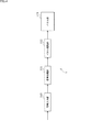
- FIG. 1 shows an example of high-luminance processing to which such high-luminance technology is applied.
- FIG. 1A shows the relationship between the input video signal and the integrated value by thick lines L11 and thick lines L12 on the same time axis.
- FIG. 1 shows the relationship between the gain multiplied by the input video signal and the integrated value by thick lines L13 and L14 on the same time axis.
- FIG. 1C shows the relationship between the output video signal obtained by multiplying the input video signal and the gain and the integrated value by thick lines L15 and L16 on the same time axis.
- the high-luminance processing shown in FIG. 1 it is possible to control the brightness improvement period for each high-luminance signal, but in the case of a pattern in which the high-luminance signal is repeatedly displayed, the brightness is improved.
- the period is virtually always continuous.
- FIG. 2 shows an example in which a repeating pattern of a high-luminance signal is displayed by the high-luminance processing.
- FIG. 2A shows the relationship between the input video signal and the integrated value by a thick line L21 and a thick line L22 in which corresponding waveforms are repeated on the same time axis.
- FIG. 2 B in FIG. 2 shows the relationship between the gain and the integrated value by a thick line L23 and a thick line L24 in which the corresponding waveforms are repeated on the same time axis.
- FIG. 2C shows the relationship between the output video signal and the integrated value by a thick line L25 and a thick line L26 in which corresponding waveforms are repeated on the same time axis.
- W conversion WCT: White Color Translation
- the sub-pixels in each pixel are performed.
- WCT White Color Translation
- a three-color lighting method is used in which one color of W and a maximum of two colors from the sub-pixels R, G, and B emit a total of three colors.
- the sub-pixel W has high efficiency without passing through a color filter. Therefore, the brightness is increased by increasing the lighting amount of the sub-pixel W.
- the amount of current of the sub-pixel W which has been increased in brightness by increasing the efficiency of the sub-pixel W without a filter and increasing the size of the sub-pixel W, is less than or equal to the maximum current amount of a single color of the sub-pixels R, G, and B. Therefore, the problem of temperature rise of the OLED display panel is unlikely to occur.
- the unused sub-pixels R, G, and B are turned on to achieve a four-color lighting state, further increasing the brightness. It can be realized.
- the load for the three sub-pixels R, G, and B increases, and the effect on the temperature rise of the OLED display panel is more than three times that of the conventional one. Therefore, the above-mentioned problems are more likely to occur. It ends up.
- FIG. 3 shows a comparative example of the three-color lighting method and the four-color lighting method.
- the input RGB video signal is represented by “Input”
- the lighting of the sub-pixels W, R, G, and B based on the video signal after W conversion is represented by “Output”.
- the four-color lighting method of "x3” is OLED compared to the three-color lighting method of "x1" and "x2". It shows that the influence of the temperature rise of the display panel is large.
- This technology proposes a method for solving the problem of temperature rise, which is a problem when increasing the brightness of the display panel as described above.
- embodiments of the present technology will be described with reference to the drawings.
- FIG. 4 shows a configuration example of an embodiment of a display device to which the present technology is applied.
- the display device 1 is a self-luminous display device such as an OLED display device having an OLED display panel.
- the display device 1 is configured as a television receiver, a display device, or the like.
- the display device 1 is composed of a signal input unit 110, a signal processing unit 111, a panel drive unit 112, and a panel unit 113.
- the signal input unit 110 is composed of a tuner connected to an antenna, a communication module that can be connected to a communication network such as the Internet, an input interface conforming to a predetermined standard, and the like.
- the signal input unit 110 records broadcast content transmitted by terrestrial broadcasting, satellite broadcasting, etc., communication content streamed via a communication network such as the Internet, or a recording medium such as an optical disk or semiconductor memory, a recorder, or the like. Video signals of various contents such as recorded contents are supplied to the signal processing unit 111.
- the signal processing unit 111 performs video signal processing on the video signal of the content supplied from the signal input unit 110, and supplies the video signal obtained as a result to the panel drive unit 112.
- high-luminance processing for changing the video signal from a low-luminance display signal (low-luminance signal) to a high-luminance display signal (high-luminance signal) is performed.
- the panel drive unit 112 drives the panel unit 113 based on the video signal supplied from the signal processing unit 111.
- the panel unit 113 includes a display panel such as an OLED display panel.
- the panel unit 113 displays images according to the images of various contents according to the drive from the panel drive unit 112.
- the OLED display panel is a display panel in which pixels including an OLED element as a self-luminous element are arranged two-dimensionally.
- An OLED Organic Light Emitting Diode
- An OLED is a light emitting element having a structure in which an organic light emitting material is sandwiched between a cathode and an anode, and constitutes pixels (display pixels) arranged two-dimensionally on an OLED display panel. ing.
- each pixel is composed of four sub-pixels of white (W), red (R), green (G), and blue (B) in the case of the WRGB method, and is an RGB method. In the case of, it is composed of three sub-pixels of red (R), green (G), and blue (B).
- the minimum configuration unit is shown for simplification of explanation, but a sound signal processing circuit that processes a sound signal, a speaker that outputs a sound corresponding to the sound signal, and the like are used. Other circuits, devices, etc. may be included.
- FIG. 5 shows a detailed configuration example of the signal processing unit 111 of FIG.
- the signal processing unit 111 includes a brightness improvement time measurement unit 131, a temperature rise amount measurement unit 132, an APL measurement unit 133, a brightness improvement gain calculation unit 134, an addition unit 135, and a multiplication unit 136.
- the input video signal from the signal input unit 110 is supplied to the luminance improvement time measurement unit 131, the temperature rise amount measurement unit 132, the APL measurement unit 133, and the multiplication unit 136, respectively.
- the brightness improvement time measurement unit 131 performs the brightness improvement time measurement process based on the video signal input therein, and supplies the measurement result of the brightness improvement time obtained as a result to the brightness improvement gain calculation unit 134. In this brightness improvement time measurement process, the time for improving the brightness on the display panel is measured. The details of the brightness improvement time measurement process will be described later with reference to FIGS. 6 and 7.
- the temperature rise amount measurement unit 132 performs the temperature rise amount measurement process based on the video signal input therein and the brightness improvement magnification, and the measurement result of the temperature rise amount obtained as a result is the brightness improvement gain calculation unit 134. Supply to. As the luminance improvement magnification, the luminance improvement magnification according to the gain multiplied by the input video signal is fed back and input. The amount of temperature rise here is regarded as the amount of short-term temperature rise.
- the measurement result of the surface temperature of the display panel supplied from the panel drive unit 112 can be used when performing the temperature rise amount measurement process. Details of the temperature rise amount measurement process will be described later with reference to FIGS. 8 to 12.
- the APL measurement unit 133 performs APL measurement processing based on the video signal input therein, and supplies the APL measurement result obtained as a result to the luminance improvement gain calculation unit 134.
- APL Average Picture Level
- APL Average Picture Level
- the brightness improvement gain calculation unit 134 includes the measurement result of the brightness improvement time from the brightness improvement time measurement unit 131, the measurement result of the temperature rise amount from the temperature rise amount measurement unit 132, and the APL measurement result from the APL measurement unit 133. Is supplied.
- the brightness improvement gain calculation unit 134 performs the brightness improvement gain calculation process based on the brightness improvement time, the amount of temperature rise, and the measurement result of APL, and supplies the brightness improvement gain obtained as a result to the addition unit 135.
- the luminance improvement gain calculation unit 134 when performing the luminance improvement gain calculation processing, the measurement result of the current flowing through the display panel supplied from the panel drive unit 112 can be used. The details of the luminance improvement gain calculation process will be described later with reference to FIGS. 15 to 17.
- the addition unit 135 adds the brightness improvement gain from the brightness improvement gain calculation unit 134 and the normal gain, and supplies the resulting high brightness gain to the multiplication unit 136.
- the normal gain is a gain that is multiplied by the input video signal, and is a gain for converting the input video signal into a high-luminance display signal.
- the normal gain the brightness improvement gain of the three-color lighting region of the WRGB method is set so that the input video signal is always high in brightness.
- an additional brightness improvement gain to the normal gain, further increase in brightness of the input video signal is realized.
- the brightness improvement gain it is possible to adaptively switch between the three-color lighting and the four-color lighting of the WRGB method.
- This additional luminance gain is adaptively controlled according to the luminance improvement time, short-term temperature rise, APL, and current load measurements.
- the multiplication unit 136 multiplies the input video signal by the high-luminance gain from the addition unit 135, and supplies the output video signal obtained as a result to the panel drive unit 112.
- the panel drive unit 112 can be provided with a panel temperature measurement unit 151 and a panel current measurement unit 152.
- the panel temperature measuring unit 151 is composed of a temperature sensor or the like provided on the panel unit 113.
- the panel temperature measuring unit 151 measures the surface temperature of the display panel, and supplies the measurement result to the temperature rise amount measuring unit 132 of the signal processing unit 111.
- a configuration example of the temperature sensor will be described later with reference to FIGS. 11 and 12.
- the panel current measuring unit 152 is composed of a current sensor or the like provided on the panel unit 113.
- the panel current measurement unit 152 measures the current applied to the display panel, and supplies the measurement result to the brightness improvement gain calculation unit 134 of the signal processing unit 111.
- the configuration of the signal processing unit 111 shown in FIG. 5 is an example, and the minimum configuration unit thereof includes a brightness improvement time measurement unit 131, a brightness improvement gain calculation unit 134, an addition unit 135, and a multiplication unit 136. And so on.
- the brightness improvement gain By controlling the brightness improvement gain with such a minimum configuration, it is possible to control the time when the brightness is higher than usual, such as lighting four colors.
- the control with this minimum configuration with the control using other measurement results, for example, the temperature rise can be suppressed even in a display pattern where the temperature rise is severe, and the brightness can be increased when the temperature has a margin. The effect can be enhanced.
- the brightness improvement time measurement unit 131 calculates the integration step value according to the input video signal level when measuring the brightness improvement time, and integrates the integration step value in the time axis direction.
- the integrated value calculated in this way corresponds to the brightness improvement time.
- FIG. 6 the relationship between the input video signal and the integrated step value when the horizontal axis is the input video signal and the vertical axis is the integrated step is shown by a thick line L31.
- FIG. 7 shows the relationship between the input video signal and the integrated value by the thick line L41 and the thick line L42 on the same time axis. That is, FIG. 7 shows the state of integration representing the brightness improvement time.
- the integrated value calculated by the brightness improvement time measuring unit 131 corresponds to the brightness improvement time
- the brightness improvement gain calculation unit 134 controls the additional brightness improvement gain according to the brightness improvement time. can do. That is, here, the process can be performed in the same manner as the high-luminance process to which the high-luminance technique shown in FIG. 1 is applied.
- the area on the screen of the display panel can be, for example, an area of the entire screen divided into a plurality of areas having predetermined sizes in the vertical direction and the horizontal direction. Specifically, it can be an area corresponding to the division area A of FIG. 12, which will be described later.
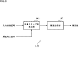
- FIG. 8 shows an example of a method for measuring the amount of temperature rise by the temperature rise amount measuring unit 132.
- the temperature rise amount measuring unit 132 includes an integration step value calculation unit 141 and an integration processing unit 142.
- the input video signal and the luminance improvement magnification are input to the integration step value calculation unit 141.
- the integration step value calculation unit 141 calculates the step value when performing the integration process according to the load increased by the brightness enhancement process.
- the positive integration step value in the high load state is made larger than the predetermined value according to the temperature that suddenly rises in the high load state, and the load is lower than the high load state.
- the negative integration step value in the low load state is set to be smaller than the predetermined value according to the temperature that slowly decreases in the load state.
- FIG. 9 the relationship between the load increase amount and the integration step value when the horizontal axis is the load increase amount and the vertical axis is the integration step is shown by a thick line L51.
- the integration processing unit 142 integrates the integration step values in the time axis direction and calculates an integration value that correlates with the temperature rise.
- FIG. 10 shows the relationship between the load increase amount and the integrated value by the thick line L61 and the thick line L62 on the same time axis. That is, FIG. 10 shows the state of integration in consideration of the temperature increase, and the integrated value represents the amount of temperature increase accompanying the increase in brightness.
- these processes are executed for each predetermined area on the screen of the display panel, and the integrated value for each predetermined area is calculated, so that the high brightness processing is performed at the same location ( It is possible to detect a state in which the temperature is rising by concentrating on the region) in a short period of time.
- the area on the screen of the display panel can be, for example, an area of the entire screen divided into a plurality of areas having predetermined sizes in the vertical direction and the horizontal direction. Specifically, it can be an area corresponding to the division area A of FIG. 12, which will be described later.
- the load of the image is predicted by signal processing, or the actual surface temperature of the display panel is measured by a temperature sensor or the like, and the temperature information obtained there is obtained for each predetermined area on the screen of the display panel.
- the accuracy can be further improved.
- Only one temperature sensor may be attached to the panel portion 113 as supplementary information for load prediction by signal processing, or a panel for the purpose of improving the accuracy of supplementary information or directly measuring without load prediction by signal processing. A plurality of them may be attached to the portion 113.
- FIG. 11 shows a configuration example of one temperature sensor provided on the panel unit 113.
- the temperature sensor 171 is attached at a position corresponding to a substantially central portion of the screen of the display panel, and measures the surface temperature of the display panel.
- the temperature sensor 171 is not limited to the position corresponding to the substantially central portion of the screen, and may be attached to another position.
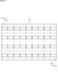
- FIG. 12 shows a configuration example of a plurality of temperature sensors provided on the panel unit 113.
- FIG. 12 shows an example in which the entire screen area of the display panel is divided into 4 ⁇ 9 areas having the same size in the vertical direction and the horizontal direction, and the temperature sensor 171 is attached to each divided area. ing. For convenience of explanation, a broken line indicating the boundary of the divided area is described on the screen of the display panel.
- the numbers corresponding to the vertical direction and the horizontal direction of the divided area A are described in the upper left divided area A11 and the lower right divided area Aij on the screen of the display panel. Further, the numbers corresponding to the vertical direction and the horizontal direction of the temperature sensor 171 are described in the temperature sensor 171-11 on the upper left and the temperature sensor 171-ij on the lower right.
- i represents a vertical number and j represents a horizontal number. That is, in FIG. 12, an example in which the screen of the display panel is divided into 4 ⁇ 9 divided areas is shown, but it is possible to divide the screen into i ⁇ j (integer of i, j: 1 or more) divided area A.
- the number of division regions A to which the temperature sensor 171 is attached is arbitrary.
- the temperature sensor 171-11 measures the surface temperature of the divided region A11 in the screen of the display panel. Since it will be repeated, the description thereof will be omitted, but the surface temperature of the divided region Aij corresponding to the mounting position is similarly measured for the temperature sensors 171-ij other than the temperature sensors 171-11.
- the temperature sensor 171 in FIG. 11 and the temperature sensors 171-11 to 171-ij in FIG. 12 correspond to the panel temperature measurement unit 151 in FIG.
- the surface temperature of the display panel can be measured more accurately than when one temperature sensor 171 is attached.
- APL Average Picture Level
- APL Average Picture Level
- the high APL state represents a state in which the APL value is higher than a predetermined value, that is, a state in which the signal level of the video signal is high.
- the low APL state represents a state in which the APL value is lower than a predetermined value, that is, a state in which the signal level of the video signal is low.
- FIG. 13 shows an example of a video signal that is greatly affected by the temperature rise.
- FIG. 13A shows a case where the entire screen of the display panel becomes an image corresponding to the image signal in a state where the signal level is high.
- FIG. 13B shows a case where the local region (white region in the figure) in the substantially central portion of the screen of the display panel becomes an image corresponding to the image signal in a state where the signal level is high.
- the APL measurement unit 133 measures the APL of the entire screen of the display panel or each predetermined area.
- the area on the screen of the display panel can be, for example, an area of the entire screen divided into a plurality of areas having predetermined sizes in the vertical direction and the horizontal direction. Specifically, it can be a region corresponding to the division region A in FIG. 12 described above.
- the OLED display panel has a different current load for the lighting amount of each pixel (OLED element) arranged two-dimensionally. If the amount of load increase due to the high brightness processing is calculated only by the above-mentioned APL measurement, it is difficult to consider the difference between these current loads. Therefore, the accuracy can be expected to be improved by measuring the current flowing through the OLED display panel with a current sensor or the like.
- the brightness improvement gain calculation unit 134 uses the APL. It suffices if the control is performed so as to relax the suppression of the luminance improvement gain according to the measurement result of.
- FIG. 14 shows the relationship between the color component of each pixel and the current value.
- the horizontal axis represents the color of the sub-pixel (White, Red, Green, Blue) and the color when the sub-pixel is lit in two colors (Yellow, Cyan, Magenta), and the vertical axis represents the panel drive current value. Shown. In each pixel, when the sub-pixels R and G are lit, the color becomes yellow (Y), when the sub-pixels R and B are lit, the color becomes magenta (M), and when the sub-pixels G and B are lit, the color becomes cyan (C). )become.
- the brightness improvement gain calculation unit 134 improves the brightness of the display panel by controlling the brightness improvement gain according to the degree of influence of the temperature rise of each element (brightness improvement time, temperature rise amount, APL, current load). When doing so, the temperature rise of the display panel is suppressed. Examples of gain setting for each element are shown in FIGS. 15 to 17.
- FIG. 15 shows an example of setting the gain with respect to the brightness improvement time.
- the horizontal axis represents the brightness improvement time (integrated value), and the vertical axis represents the brightness improvement time interlocking gain.
- the gain according to the brightness improvement time is indicated by a thick line L81 including a straight line descending to the right, and the brightness improvement time interlocking gain is maintained at 100% until the integrated value reaches a predetermined value.
- the integrated value exceeds the predetermined value, it gradually decreases with a predetermined slope, and after it decreases to 0%, it continues to be 0% as it is.
- FIG. 16 shows an example of setting the gain with respect to the amount of temperature rise.
- the horizontal axis represents the amount of temperature rise (integrated value), and the vertical axis represents the gain linked to the amount of temperature rise.
- the gain according to the amount of temperature rise is indicated by a thick line L82 including a straight line falling to the right, and the gain of this amount of temperature rise is maintained at 100% until the integrated value reaches a predetermined value. , After the integrated value exceeds the predetermined value, it gradually decreases with a predetermined slope, and after it decreases to 0%, it continues to be 0% as it is.
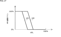
- FIG. 17 shows an example of gain setting for APL.
- the horizontal axis represents APL and the vertical axis represents APL-linked gain.
- the value of APL on the horizontal axis is a value in the range of 0% to 100%.
- the gain corresponding to the APL is indicated by thick lines L83 and L84 including a straight line descending to the right.
- the thick line L83 shows the APL interlocking gain when the measured amount of the current load is high
- the thick line L84 shows the APL interlocking gain when the measured amount of the current load is low.
- the APL interlocking gain is maintained at 100% until the APL value reaches the predetermined value, but gradually decreases with a predetermined slope after the APL value exceeds the predetermined value. After decreasing to 0%, continue 0% as it is.
- the thick wire L83 has a smaller APL value until the APL interlocking gain decreases than the thick wire L84, and when the measured amount of the current load is high, the APL interlocking gain decreases with a smaller APL value. become.
- the APL interlocking gain may be set according to the APL without considering the current load.
- such interlocking gains are set, and for example, a value obtained by multiplying these interlocking gain values, a minimum value among these interlocking gain values, and the like are finally used for brightness improvement. Set as gain.
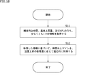
- FIG. 18 is a flowchart illustrating the flow of the luminance improvement gain control process executed by the signal processing unit 111.
- step S11 the luminance improvement gain calculation unit 134 acquires at least one piece of information among the luminance improvement time measurement result, the temperature rise amount measurement result, and the APL measurement result.
- the measurement result of the current flowing through the display panel may be acquired.
- step S12 the brightness improvement gain calculation unit 134 adaptively controls the brightness improvement gain according to the degree of influence of the temperature rise based on the acquired information.
- the value obtained by multiplying the gain is set as the final brightness improvement gain.
- the brightness improvement time and the display panel are measured by measuring the time for improving the brightness in the display panel.
- the brightness improvement gain is affected by the temperature rise of the display panel based on at least one information of the short-term temperature rise amount of the above and the feature amount (for example, APL) of the video signal according to the image displayed on the display panel. It is controlled adaptively while estimating the degree.
- the signal processing unit 111 has been described as a component of the display device 1, but the signal processing unit 111 may be regarded as a single device and may be a signal processing device.
- the display device 1 is a television receiver
- a device such as a display device may be used.
- the display device includes, for example, a monitor for medical use, a monitor for broadcasting, a display for digital signage, and the like.
- the display device 1 can be used as a PC (Personal Computer), a tablet terminal, a smartphone, a mobile phone, a game machine, a head-mounted display, an in-vehicle device such as a car navigation system or a monitor for a rear seat, a wearable device such as a wristwatch type or a glasses type, and the like. It may be used as a display unit of.
- PC Personal Computer
- tablet terminal a smartphone
- a mobile phone such as a game machine
- a head-mounted display such as a car navigation system or a monitor for a rear seat
- a wearable device such as a wristwatch type or a glasses type, and the like. It may be used as a display unit of.
- the display device 1 is an example of an OLED display device having an OLED display panel, but the present technology can also be applied to a display device such as a self-luminous display device having another self-luminous display panel. be.
- each pixel arranged two-dimensionally on the panel unit 113 is composed of four sub-pixels of white (W), red (R), green (G), and blue (B).
- W white
- R red
- G green
- B blue
- the color of the sub-pixel is not limited to these.
- a sub-pixel of another color having the same high visual sensitivity as the white (W) may be used.
- OLED may be read as “organic EL (Electro Luminescence)".
- OLED display device can be said to be an organic EL display device.
- video since the video is composed of a plurality of image frames, "video” may be read as "image”.
- a signal processing device including a signal processing unit that adaptively controls a first gain for improving the brightness of the video signal based on the acquired information according to the degree of influence of a temperature rise on the display panel.
- the signal processing unit additionally adds the first gain to the second gain used for increasing the brightness, thereby realizing the increase in brightness of the video signal (1). Or the signal processing device according to (2).
- the signal processing unit uses a value corresponding to the interlocking gain linked to at least one information of the brightness improvement time, the temperature rise amount, and the feature amount as the first gain (1) to (3). ).
- the signal processing device according to any one of. (5)
- the signal processing unit uses a value obtained by multiplying the plurality of interlocking gain values or a minimum value among the plurality of interlocking gain values as the first gain.
- the signal processing unit Calculate the integration step value according to the level of the video signal, The signal processing device according to any one of (1) to (5) above, wherein the calculated integrated step value is integrated in the time axis direction to calculate the integrated value according to the brightness improvement time. (7) The signal processing device according to (6), wherein the signal processing unit calculates an integrated value according to the brightness improvement time for each predetermined area on the screen of the display panel. (8) The signal processing unit Calculate the integration step value when performing integration according to the load that increases due to the increase in brightness. The signal processing apparatus according to any one of (1) to (7) above, wherein the calculated integrated step values are integrated in the time axis direction to calculate the integrated value according to the temperature rise.
- the signal processing unit sets a positive integration step value corresponding to the high load state to be larger than a predetermined value, and sets the load to a low load state lower than the high load state.
- the signal processing apparatus according to (8) above, wherein the corresponding negative integration step value is set to be smaller than a predetermined value.
- the signal processing device according to (8) or (9), wherein the signal processing unit calculates an integrated value according to the temperature rise for each predetermined area on the screen of the display panel.
- the signal processing unit adds information on the temperature obtained by predicting the load of the image or measuring the temperature sensor provided on the display panel to the integrated value according to the temperature rise (8) to (10).
- the signal processing apparatus according to any one of.
- the signal processing device (12) The signal processing device according to (11), wherein one or a plurality of temperature sensors for measuring the surface temperature are provided on the display panel. (13) The signal processing device according to any one of (1) to (12) above, wherein the feature amount is APL. (14) The signal processing device according to (13), wherein the signal processing unit measures the APL for the entire screen of the display panel or for each predetermined area on the screen. (15) The signal processing device according to (4), wherein the signal processing unit adds the measurement result of the current flowing through the display panel to the interlocking gain linked to the feature amount.
- the signal processing device When the video signal is increased in brightness from a low-luminance display signal to a high-luminance display signal, the brightness improvement time measured by measuring the time for improving the brightness in the display panel, the amount of temperature rise in the display panel, and the display panel Acquire at least one piece of information among the feature quantities of the video signal according to the displayed video, A signal processing method that adaptively controls a first gain for improving the brightness of the video signal based on the acquired information according to the degree of influence of a temperature rise on the display panel. (17) A signal processing unit that processes video signals and A panel unit having a display panel for displaying an image corresponding to the image signal is provided.
- the signal processing unit When the video signal is increased in brightness from a low-luminance display signal to a high-luminance display signal, the brightness improvement time measured by measuring the time for improving the brightness in the display panel, the amount of temperature rise in the display panel, and the display. Acquire at least one piece of information among the feature quantities of the video signal corresponding to the video displayed on the panel.
- a display device that adaptively controls a first gain for improving the brightness of the video signal based on the acquired information according to the degree of influence of a temperature rise on the display panel.
- Display device 110 signal input unit, 111 signal processing unit, 112 panel drive unit, 113 panel unit, 131 brightness improvement time measurement unit, 132 temperature rise measurement unit, 133 APL measurement unit, 134 brightness improvement gain calculation unit, 135 Addition unit, 136 multiplication unit, 151 panel temperature measurement unit, 152 panel current measurement unit, 171 temperature sensor
Abstract
The present technology relates to a signal processing device, a signal processing method, and a display device that make it possible to suppress the temperature rise of a display panel. Provided is a signal processing device equipped with a signal processing unit that, when the brightness of an image signal is increased from a low brightness display signal to a high brightness display signal, acquires at least one information among a brightness increase time obtained by measuring the time during which the brightness on a display panel is increased, the temperature rise amount of the display panel, and the feature amount of the image signal corresponding to an image displayed on the display panel, and on the basis of the acquired information, adaptively controls a first gain for increasing the brightness of the image signal according to the degree of influence of temperature rise of the display panel. The present technology can be applied to, for example, a self-luminous display device.
Description
本技術は、信号処理装置、信号処理方法、及び表示装置に関し、特に、表示パネルの温度上昇を抑制することができるようにした信号処理装置、信号処理方法、及び表示装置に関する。
The present technology relates to a signal processing device, a signal processing method, and a display device, and more particularly to a signal processing device, a signal processing method, and a display device capable of suppressing a temperature rise of a display panel.
近年、映像を表示する表示デバイスとしてOLED表示装置等の自発光型表示装置が主流になりつつある。例えば、特許文献1には、自発光型表示装置等の表示装置に関する技術として、表示パネルの高輝度化に関する技術について開示されている。
In recent years, self-luminous display devices such as OLED display devices are becoming mainstream as display devices for displaying images. For example, Patent Document 1 discloses a technique for increasing the brightness of a display panel as a technique for a display device such as a self-luminous display device.
ところで、表示装置では、表示パネルの高輝度化を実施するに際して、表示パネルの温度上昇を抑制することが求められている。
By the way, in the display device, it is required to suppress the temperature rise of the display panel when the brightness of the display panel is increased.
本技術はこのような状況に鑑みてなされたものであり、表示パネルの温度上昇を抑制することができるようにするものである。
This technology was made in view of such a situation, and makes it possible to suppress the temperature rise of the display panel.
本技術の一側面の信号処理装置は、映像信号を低輝度表示の信号から高輝度表示の信号に高輝度化するに際して、表示パネルにおける輝度を向上させた時間を計測した輝度向上時間、前記表示パネルの温度上昇量、及び前記表示パネルに表示される映像に応じた映像信号の特徴量のうち、少なくとも1つの情報を取得し、取得した情報に基づいて、前記映像信号の輝度を向上させるための第1のゲインを、前記表示パネルの温度上昇の影響度に応じて適応的に制御する信号処理部を備える信号処理装置である。
The signal processing device on one aspect of the present technology measures the time for improving the brightness of the display panel when the video signal is changed from the low-brightness display signal to the high-brightness display signal. To acquire at least one piece of information from the amount of temperature rise of the panel and the feature amount of the video signal according to the image displayed on the display panel, and to improve the brightness of the image signal based on the acquired information. This is a signal processing device including a signal processing unit that adaptively controls the first gain of the above according to the degree of influence of the temperature rise of the display panel.
本技術の一側面の信号処理方法は、信号処理装置が、映像信号を低輝度表示の信号から高輝度表示の信号に高輝度化するに際して、表示パネルにおける輝度を向上させた時間を計測した輝度向上時間、前記表示パネルの温度上昇量、及び前記表示パネルに表示される映像に応じた映像信号の特徴量のうち、少なくとも1つの情報を取得し、取得した情報に基づいて、前記映像信号の輝度を向上させるための第1のゲインを、前記表示パネルの温度上昇の影響度に応じて適応的に制御する信号処理方法である。
In the signal processing method of one aspect of the present technology, when the signal processing device increases the brightness of the video signal from the low-brightness display signal to the high-brightness display signal, the brightness is measured by measuring the time during which the brightness of the display panel is improved. At least one of the improvement time, the amount of temperature rise of the display panel, and the feature amount of the video signal corresponding to the image displayed on the display panel is acquired, and based on the acquired information, the image signal of the image signal is acquired. This is a signal processing method in which the first gain for improving the brightness is adaptively controlled according to the degree of influence of the temperature rise of the display panel.
本技術の一側面の信号処理装置、及び信号処理方法においては、映像信号を低輝度表示の信号から高輝度表示の信号に高輝度化するに際して、表示パネルにおける輝度を向上させた時間を計測した輝度向上時間、前記表示パネルの温度上昇量、及び前記表示パネルに表示される映像に応じた映像信号の特徴量のうち、少なくとも1つの情報が取得され、取得された情報に基づいて、前記映像信号の輝度を向上させるための第1のゲインが、前記表示パネルの温度上昇の影響度に応じて適応的に制御される。
In the signal processing device and the signal processing method of one aspect of the present technology, when the video signal is increased in brightness from the low-luminance display signal to the high-luminance display signal, the time for improving the brightness in the display panel is measured. At least one of the brightness improvement time, the amount of temperature rise of the display panel, and the feature amount of the video signal corresponding to the image displayed on the display panel is acquired, and the image is based on the acquired information. The first gain for improving the brightness of the signal is adaptively controlled according to the degree of influence of the temperature rise of the display panel.
本技術の一側面の表示装置は、表示パネルを有するパネル部と、映像信号を処理する信号処理部とを備え、前記信号処理部は、前記映像信号を低輝度表示の信号から高輝度表示の信号に高輝度化するに際して、前記表示パネルにおける輝度を向上させた時間を計測した輝度向上時間、前記表示パネルの温度上昇量、及び前記表示パネルに表示される映像に応じた映像信号の特徴量のうち、少なくとも1つの情報を取得し、取得した情報に基づいて、前記映像信号の輝度を向上させるための第1のゲインを、前記表示パネルの温度上昇の影響度に応じて適応的に制御する信号処理部を備える表示装置である。
The display device on one aspect of the present technology includes a panel unit having a display panel and a signal processing unit that processes a video signal, and the signal processing unit displays the video signal from a low-brightness display signal to a high-brightness display. When increasing the brightness of a signal, the brightness improvement time measured by measuring the time for improving the brightness of the display panel, the amount of temperature rise of the display panel, and the feature amount of the video signal according to the image displayed on the display panel. Of these, at least one piece of information is acquired, and based on the acquired information, the first gain for improving the brightness of the video signal is adaptively controlled according to the degree of influence of the temperature rise of the display panel. It is a display device provided with a signal processing unit.
本技術の一側面の表示装置においては、映像信号を低輝度表示の信号から高輝度表示の信号に高輝度化するに際して、表示パネルにおける輝度を向上させた時間を計測した輝度向上時間、前記表示パネルの温度上昇量、及び前記表示パネルに表示される映像に応じた映像信号の特徴量のうち、少なくとも1つの情報が取得され、取得された情報に基づいて、前記映像信号の輝度を向上させるための第1のゲインが、前記表示パネルの温度上昇の影響度に応じて適応的に制御される。
In the display device on one aspect of the present technology, when the video signal is increased in brightness from a low-luminance display signal to a high-luminance display signal, the brightness improvement time obtained by measuring the time for which the brightness in the display panel is improved is the display. At least one piece of information is acquired from the amount of temperature rise of the panel and the feature amount of the video signal according to the image displayed on the display panel, and the brightness of the image signal is improved based on the acquired information. The first gain for this is adaptively controlled according to the degree of influence of the temperature rise of the display panel.
本技術の一側面の信号処理装置、及び表示装置は、独立した装置であってもよいし、1つの装置を構成している内部ブロックであってもよい。
The signal processing device and the display device on one aspect of the present technology may be independent devices or internal blocks constituting one device.
<1.本技術の実施の形態>
<1. Embodiment of this technology>
OLED表示装置等の表示装置の高輝度化技術として、映像信号が低輝度表示の信号(低輝度信号)から高輝度表示の信号(高輝度信号)に切り替わるのを検出して、増加する積算値に基づき輝度向上ゲインを制御する技術がある(上述の特許文献1参照)。
As a technique for increasing the brightness of display devices such as OLED display devices, it is detected that the video signal is switched from a low-brightness display signal (low-brightness signal) to a high-brightness display signal (high-brightness signal), and the integrated value is increased. There is a technique for controlling the luminance improvement gain based on the above (see Patent Document 1 described above).
図1は、このような高輝度化技術を適用した高輝度化処理の例を示している。図1のAは、入力映像信号と積算値との関係を、同一時間軸上で太線L11と太線L12により示している。
FIG. 1 shows an example of high-luminance processing to which such high-luminance technology is applied. FIG. 1A shows the relationship between the input video signal and the integrated value by thick lines L11 and thick lines L12 on the same time axis.
図1のBは、入力映像信号に乗じられるゲインと積算値との関係を、同一時間軸上で太線L13と太線L14により示している。図1のCは、入力映像信号とゲインとを乗じて得られる出力映像信号と積算値との関係を、同一時間軸上で太線L15と太線L16により示している。
B in FIG. 1 shows the relationship between the gain multiplied by the input video signal and the integrated value by thick lines L13 and L14 on the same time axis. FIG. 1C shows the relationship between the output video signal obtained by multiplying the input video signal and the gain and the integrated value by thick lines L15 and L16 on the same time axis.
図1に示した高輝度化処理を用いた場合、高輝度信号に関して1回あたりの輝度向上期間を制御することは可能であるが、高輝度信号が繰り返し表示されるパターンの場合に、輝度向上期間が実質的に常に続いてしまう。
When the high-luminance processing shown in FIG. 1 is used, it is possible to control the brightness improvement period for each high-luminance signal, but in the case of a pattern in which the high-luminance signal is repeatedly displayed, the brightness is improved. The period is virtually always continuous.
図2は、高輝度化処理で高輝度信号の繰り返しパターンを表示した場合の例を示している。図2のAは、入力映像信号と積算値との関係を、同一時間軸上で対応する波形が繰り返される太線L21と太線L22により示している。
FIG. 2 shows an example in which a repeating pattern of a high-luminance signal is displayed by the high-luminance processing. FIG. 2A shows the relationship between the input video signal and the integrated value by a thick line L21 and a thick line L22 in which corresponding waveforms are repeated on the same time axis.
図2のBは、ゲインと積算値との関係を、同一時間軸上で対応する波形が繰り返される太線L23と太線L24により示している。図2のCは、出力映像信号と積算値との関係を、同一時間軸上で対応する波形が繰り返される太線L25と太線L26により示している。
B in FIG. 2 shows the relationship between the gain and the integrated value by a thick line L23 and a thick line L24 in which the corresponding waveforms are repeated on the same time axis. FIG. 2C shows the relationship between the output video signal and the integrated value by a thick line L25 and a thick line L26 in which corresponding waveforms are repeated on the same time axis.
このように、高輝度化処理を用いた場合に、高輝度信号が繰り返し表示されるパターンとなるとき、輝度向上期間が実質的に常に続いてしまい、表示装置では、表示パネルの温度が上昇してしまう恐れがある。
In this way, when the high-luminance processing is used and the high-luminance signal is repeatedly displayed in a pattern, the brightness improvement period is substantially always continued, and the temperature of the display panel in the display device rises. There is a risk that it will end up.
また、単一の輝度向上期間しかみていないため、高負荷映像が表示されて、既に表示パネルが高温になっている状態でも、高輝度化処理を実施してしまう恐れがある。
Also, since only a single brightness improvement period is viewed, there is a risk that the brightness increase processing will be performed even when a high-load image is displayed and the display panel is already hot.
これらの問題があるため、表示パネルの温度上昇が問題にならない程度にまで、輝度向上期間を短く、又は輝度向上ゲインを低くなるように設定する必要があり、高輝度化の効果を大きくすることができないという問題がある。
Due to these problems, it is necessary to set the brightness improvement period to be short or the brightness improvement gain to be low so that the temperature rise of the display panel does not become a problem, and the effect of increasing the brightness should be increased. There is a problem that it cannot be done.
OLED表示装置では、OLED表示パネルに2次元状に配置される画素がWRGB画素である場合、入力されるRGB映像信号に対してW変換(WCT:White Color Translation)を行い、各画素におけるサブ画素Wの1色と、サブ画素R,G,Bの中から最大2色の計3色が発光する3色点灯方式を通常は使用している。
In the OLED display device, when the pixels arranged in two dimensions on the OLED display panel are WRGB pixels, W conversion (WCT: White Color Translation) is performed on the input RGB video signal, and the sub-pixels in each pixel are performed. Normally, a three-color lighting method is used in which one color of W and a maximum of two colors from the sub-pixels R, G, and B emit a total of three colors.
このようなWRGB方式のOLED表示パネルにおいて、サブ画素Wは、サブ画素R,G,Bと異なり、カラーフィルタを通さず高効率となるため、サブ画素Wの点灯量を上げることで高輝度化を実現する手法がある。この手法では、サブ画素Wのフィルタレスによる高効率、及びサブ画素Wのサイズの拡大により、高輝度化したサブ画素Wの電流量を、サブ画素R,G,Bの単色の最大電流量以下とすることもできるため、OLED表示パネルの温度上昇の問題は起きにくい。
In such a WRGB type OLED display panel, unlike the sub-pixels R, G, and B, the sub-pixel W has high efficiency without passing through a color filter. Therefore, the brightness is increased by increasing the lighting amount of the sub-pixel W. There is a method to realize. In this method, the amount of current of the sub-pixel W, which has been increased in brightness by increasing the efficiency of the sub-pixel W without a filter and increasing the size of the sub-pixel W, is less than or equal to the maximum current amount of a single color of the sub-pixels R, G, and B. Therefore, the problem of temperature rise of the OLED display panel is unlikely to occur.
一方で、WRGB方式のOLED表示パネルにおいて、サブ画素Wの点灯量が飽和した後に、使用していないサブ画素R,G,Bを点灯させることで、4色点灯状態となり、さらなる高輝度化を実現することができる。しかしながら、サブ画素R,G,Bの3画素分の負荷が増えてしまい、OLED表示パネルの温度上昇への影響が従来の3倍以上となるため、上述した問題がより顕著に発生しやすくなってしまう。
On the other hand, in the WRGB type OLED display panel, after the lighting amount of the sub-pixel W is saturated, the unused sub-pixels R, G, and B are turned on to achieve a four-color lighting state, further increasing the brightness. It can be realized. However, the load for the three sub-pixels R, G, and B increases, and the effect on the temperature rise of the OLED display panel is more than three times that of the conventional one. Therefore, the above-mentioned problems are more likely to occur. It ends up.
図3は、3色点灯方式と4色点灯方式の比較例を示している。図3においては、入力されるRGB映像信号を、「Input」で表し、W変換後の映像信号に基づいたサブ画素W,R,G,Bの点灯を、「Output」で表している。また、「×1」,「×2」,「×3」の倍率によって、「×3」の4色点灯方式は、「×1」,「×2」の3色点灯方式と比べて、OLED表示パネルの温度上昇の影響が大きいことを表している。
FIG. 3 shows a comparative example of the three-color lighting method and the four-color lighting method. In FIG. 3, the input RGB video signal is represented by “Input”, and the lighting of the sub-pixels W, R, G, and B based on the video signal after W conversion is represented by “Output”. In addition, depending on the magnification of "x1", "x2", and "x3", the four-color lighting method of "x3" is OLED compared to the three-color lighting method of "x1" and "x2". It shows that the influence of the temperature rise of the display panel is large.
本技術では、以上のような表示パネルの高輝度化を実施する際に問題となる温度上昇に関する問題を解決するための手法を提案する。以下、図面を参照しながら、本技術の実施の形態を説明する。
This technology proposes a method for solving the problem of temperature rise, which is a problem when increasing the brightness of the display panel as described above. Hereinafter, embodiments of the present technology will be described with reference to the drawings.
(装置構成)
図4は、本技術を適用した表示装置の一実施の形態の構成例を示している。 (Device configuration)
FIG. 4 shows a configuration example of an embodiment of a display device to which the present technology is applied.
図4は、本技術を適用した表示装置の一実施の形態の構成例を示している。 (Device configuration)
FIG. 4 shows a configuration example of an embodiment of a display device to which the present technology is applied.
表示装置1は、OLED表示パネルを有するOLED表示装置などの自発光型表示装置である。表示装置1は、テレビ受像機やディスプレイ装置などとして構成される。
The display device 1 is a self-luminous display device such as an OLED display device having an OLED display panel. The display device 1 is configured as a television receiver, a display device, or the like.
図4において、表示装置1は、信号入力部110、信号処理部111、パネル駆動部112、及びパネル部113から構成される。
In FIG. 4, the display device 1 is composed of a signal input unit 110, a signal processing unit 111, a panel drive unit 112, and a panel unit 113.
信号入力部110は、アンテナに接続されたチューナ、インターネット等の通信網に接続可能な通信モジュール、又は所定の規格に準拠した入力インターフェースなどから構成される。
The signal input unit 110 is composed of a tuner connected to an antenna, a communication module that can be connected to a communication network such as the Internet, an input interface conforming to a predetermined standard, and the like.
信号入力部110は、地上波放送や衛星放送などにより送信される放送コンテンツ、インターネット等の通信網を介してストリーミング配信される通信コンテンツ、又は光ディスクや半導体メモリ等の記録媒体や録画機などに記録された記録コンテンツなどの各種のコンテンツの映像信号を、信号処理部111に供給する。
The signal input unit 110 records broadcast content transmitted by terrestrial broadcasting, satellite broadcasting, etc., communication content streamed via a communication network such as the Internet, or a recording medium such as an optical disk or semiconductor memory, a recorder, or the like. Video signals of various contents such as recorded contents are supplied to the signal processing unit 111.
信号処理部111は、信号入力部110から供給されるコンテンツの映像信号に対する映像信号処理を行い、その結果得られる映像信号を、パネル駆動部112に供給する。この映像信号処理では、映像信号を、低輝度表示の信号(低輝度信号)から高輝度表示の信号(高輝度信号)にする高輝度化処理などが実施される。
The signal processing unit 111 performs video signal processing on the video signal of the content supplied from the signal input unit 110, and supplies the video signal obtained as a result to the panel drive unit 112. In this video signal processing, high-luminance processing for changing the video signal from a low-luminance display signal (low-luminance signal) to a high-luminance display signal (high-luminance signal) is performed.
パネル駆動部112は、信号処理部111から供給される映像信号に基づいて、パネル部113を駆動する。
The panel drive unit 112 drives the panel unit 113 based on the video signal supplied from the signal processing unit 111.
パネル部113は、OLED表示パネルなどの表示パネルを含んで構成される。パネル部113は、パネル駆動部112からの駆動に従い、各種のコンテンツの映像に応じた映像の表示を行う。
The panel unit 113 includes a display panel such as an OLED display panel. The panel unit 113 displays images according to the images of various contents according to the drive from the panel drive unit 112.
OLED表示パネルは、自発光素子としてのOLED素子を含む画素を2次元状に配置した表示パネルである。OLED(Organic Light Emitting Diode)は、陰極と陽極との間に有機発光材料を挟んだ構造からなる発光素子であって、OLED表示パネルに2次元状に配置される画素(表示画素)を構成している。
The OLED display panel is a display panel in which pixels including an OLED element as a self-luminous element are arranged two-dimensionally. An OLED (Organic Light Emitting Diode) is a light emitting element having a structure in which an organic light emitting material is sandwiched between a cathode and an anode, and constitutes pixels (display pixels) arranged two-dimensionally on an OLED display panel. ing.
OLED表示パネルにおいて、各画素(表示画素)は、WRGB方式の場合には、白色(W),赤色(R),緑色(G),青色(B)の4つのサブ画素から構成され、RGB方式の場合には、赤色(R),緑色(G),青色(B)の3つのサブ画素から構成される。
In the OLED display panel, each pixel (display pixel) is composed of four sub-pixels of white (W), red (R), green (G), and blue (B) in the case of the WRGB method, and is an RGB method. In the case of, it is composed of three sub-pixels of red (R), green (G), and blue (B).
なお、図4に示した構成では、説明の簡略化のため、最小限の構成単位を示したが、音信号を処理する音信号処理回路や、音信号に応じた音を出力するスピーカなど、他の回路やデバイス等を含めても構わない。
In the configuration shown in FIG. 4, the minimum configuration unit is shown for simplification of explanation, but a sound signal processing circuit that processes a sound signal, a speaker that outputs a sound corresponding to the sound signal, and the like are used. Other circuits, devices, etc. may be included.
図5は、図4の信号処理部111の詳細な構成例を示している。
FIG. 5 shows a detailed configuration example of the signal processing unit 111 of FIG.
図5において、信号処理部111は、輝度向上時間計測部131、温度上昇量計測部132、APL計測部133、輝度向上ゲイン算出部134、加算部135、及び乗算部136を有する。
In FIG. 5, the signal processing unit 111 includes a brightness improvement time measurement unit 131, a temperature rise amount measurement unit 132, an APL measurement unit 133, a brightness improvement gain calculation unit 134, an addition unit 135, and a multiplication unit 136.
信号処理部111においては、信号入力部110からの入力映像信号が、輝度向上時間計測部131、温度上昇量計測部132、APL計測部133、及び乗算部136にそれぞれ供給される。
In the signal processing unit 111, the input video signal from the signal input unit 110 is supplied to the luminance improvement time measurement unit 131, the temperature rise amount measurement unit 132, the APL measurement unit 133, and the multiplication unit 136, respectively.
輝度向上時間計測部131は、そこに入力される映像信号に基づいて、輝度向上時間計測処理を行い、その結果得られる輝度向上時間の計測結果を、輝度向上ゲイン算出部134に供給する。この輝度向上時間計測処理では、表示パネルにおける輝度を向上させた時間が計測される。輝度向上時間計測処理の詳細は、図6,図7を参照して後述する。
The brightness improvement time measurement unit 131 performs the brightness improvement time measurement process based on the video signal input therein, and supplies the measurement result of the brightness improvement time obtained as a result to the brightness improvement gain calculation unit 134. In this brightness improvement time measurement process, the time for improving the brightness on the display panel is measured. The details of the brightness improvement time measurement process will be described later with reference to FIGS. 6 and 7.
温度上昇量計測部132は、そこに入力される映像信号と、輝度向上倍率に基づいて、温度上昇量計測処理を行い、その結果得られる温度上昇量の計測結果を、輝度向上ゲイン算出部134に供給する。輝度向上倍率としては、入力映像信号に乗じられるゲインに応じた輝度向上倍率がフィードバックされて入力される。ここでの温度上昇量は、短期的な温度の上昇量とされる。
The temperature rise amount measurement unit 132 performs the temperature rise amount measurement process based on the video signal input therein and the brightness improvement magnification, and the measurement result of the temperature rise amount obtained as a result is the brightness improvement gain calculation unit 134. Supply to. As the luminance improvement magnification, the luminance improvement magnification according to the gain multiplied by the input video signal is fed back and input. The amount of temperature rise here is regarded as the amount of short-term temperature rise.
また、温度上昇量計測部132では、温度上昇量計測処理を行うに際して、パネル駆動部112から供給される、表示パネルの表面温度の計測結果を用いることができる。温度上昇量計測処理の詳細は、図8乃至図12を参照して後述する。
Further, in the temperature rise amount measurement unit 132, the measurement result of the surface temperature of the display panel supplied from the panel drive unit 112 can be used when performing the temperature rise amount measurement process. Details of the temperature rise amount measurement process will be described later with reference to FIGS. 8 to 12.
APL計測部133は、そこに入力される映像信号に基づいて、APL計測処理を行い、その結果得られるAPLの計測結果を、輝度向上ゲイン算出部134に供給する。このAPL計測処理では、表示パネルに表示される映像に応じた映像信号の特徴量として、APL(Average Picture Level)が計測される。APL計測処理の詳細は、図13を参照して後述する。
The APL measurement unit 133 performs APL measurement processing based on the video signal input therein, and supplies the APL measurement result obtained as a result to the luminance improvement gain calculation unit 134. In this APL measurement process, APL (Average Picture Level) is measured as a feature amount of a video signal corresponding to the video displayed on the display panel. Details of the APL measurement process will be described later with reference to FIG.
輝度向上ゲイン算出部134には、輝度向上時間計測部131からの輝度向上時間の計測結果、温度上昇量計測部132からの温度上昇量の計測結果、及びAPL計測部133からのAPLの計測結果が供給される。輝度向上ゲイン算出部134は、輝度向上時間、温度上昇量、及びAPLの計測結果に基づいて、輝度向上ゲイン算出処理を行い、その結果得られる輝度向上ゲインを、加算部135に供給する。
The brightness improvement gain calculation unit 134 includes the measurement result of the brightness improvement time from the brightness improvement time measurement unit 131, the measurement result of the temperature rise amount from the temperature rise amount measurement unit 132, and the APL measurement result from the APL measurement unit 133. Is supplied. The brightness improvement gain calculation unit 134 performs the brightness improvement gain calculation process based on the brightness improvement time, the amount of temperature rise, and the measurement result of APL, and supplies the brightness improvement gain obtained as a result to the addition unit 135.
また、輝度向上ゲイン算出部134では、輝度向上ゲイン算出処理を行うに際して、パネル駆動部112から供給される、表示パネルに流れる電流の計測結果を用いることができる。輝度向上ゲイン算出処理の詳細は、図15乃至図17を参照して後述する。
Further, in the luminance improvement gain calculation unit 134, when performing the luminance improvement gain calculation processing, the measurement result of the current flowing through the display panel supplied from the panel drive unit 112 can be used. The details of the luminance improvement gain calculation process will be described later with reference to FIGS. 15 to 17.
加算部135は、輝度向上ゲイン算出部134からの輝度向上ゲインと、通常時ゲインとを加算して、その結果得られる高輝度化ゲインを、乗算部136に供給する。
The addition unit 135 adds the brightness improvement gain from the brightness improvement gain calculation unit 134 and the normal gain, and supplies the resulting high brightness gain to the multiplication unit 136.
通常時ゲインは、入力映像信号に乗じられるゲインであって、入力映像信号を高輝度表示の信号にするためのゲインである。例えば、通常時ゲインとしては、WRGB方式の3色点灯領域の輝度向上ゲインなどを設定することで、常に入力映像信号が高輝度化されるようにする。
The normal gain is a gain that is multiplied by the input video signal, and is a gain for converting the input video signal into a high-luminance display signal. For example, as the normal gain, the brightness improvement gain of the three-color lighting region of the WRGB method is set so that the input video signal is always high in brightness.
ここでは、通常時ゲインに対して、付加的な輝度向上ゲインを加算することで、入力映像信号のさらなる高輝度化が実現される。例えば、輝度向上ゲインの加算によって、WRGB方式の3色点灯と4色点灯を適応的に切り替えることができる。この付加的な輝度向上ゲインは、輝度向上時間、短期的な温度上昇量、APL、及び電流負荷の計測結果に応じて、適応的に制御される。
Here, by adding an additional brightness improvement gain to the normal gain, further increase in brightness of the input video signal is realized. For example, by adding the brightness improvement gain, it is possible to adaptively switch between the three-color lighting and the four-color lighting of the WRGB method. This additional luminance gain is adaptively controlled according to the luminance improvement time, short-term temperature rise, APL, and current load measurements.
乗算部136は、入力映像信号に対し、加算部135からの高輝度化ゲインを乗算して、その結果得られる出力映像信号を、パネル駆動部112に供給する。
The multiplication unit 136 multiplies the input video signal by the high-luminance gain from the addition unit 135, and supplies the output video signal obtained as a result to the panel drive unit 112.
図5において、パネル駆動部112は、パネル温度計測部151、及びパネル電流計測部152を設けることができる。
In FIG. 5, the panel drive unit 112 can be provided with a panel temperature measurement unit 151 and a panel current measurement unit 152.
パネル温度計測部151は、パネル部113に設けられた温度センサ等から構成される。パネル温度計測部151は、表示パネルの表面温度を計測し、その計測結果を、信号処理部111の温度上昇量計測部132に供給する。温度センサの構成例は、図11,図12を参照して後述する。
The panel temperature measuring unit 151 is composed of a temperature sensor or the like provided on the panel unit 113. The panel temperature measuring unit 151 measures the surface temperature of the display panel, and supplies the measurement result to the temperature rise amount measuring unit 132 of the signal processing unit 111. A configuration example of the temperature sensor will be described later with reference to FIGS. 11 and 12.
パネル電流計測部152は、パネル部113に設けられた電流センサ等から構成される。パネル電流計測部152は、表示パネルに印加される電流を計測し、その計測結果を、信号処理部111の輝度向上ゲイン算出部134に供給する。
The panel current measuring unit 152 is composed of a current sensor or the like provided on the panel unit 113. The panel current measurement unit 152 measures the current applied to the display panel, and supplies the measurement result to the brightness improvement gain calculation unit 134 of the signal processing unit 111.
なお、図5に示した信号処理部111の構成は一例であり、その最小の構成単位は、輝度向上時間計測部131、輝度向上ゲイン算出部134、加算部135、及び乗算部136を含む構成などとすることができる。
The configuration of the signal processing unit 111 shown in FIG. 5 is an example, and the minimum configuration unit thereof includes a brightness improvement time measurement unit 131, a brightness improvement gain calculation unit 134, an addition unit 135, and a multiplication unit 136. And so on.
このような最小の構成での輝度向上ゲインの制御によっても、4色点灯などの通常よりも高輝度化している時間を制御可能である。また、この最小の構成での制御に、その他の計測結果を用いた制御を組み合わせることで、例えば、温度上昇に厳しい表示パターンでも温度上昇を抑えたり、温度に余裕がある状態で高輝度化の効果を高めたりすることができる。
By controlling the brightness improvement gain with such a minimum configuration, it is possible to control the time when the brightness is higher than usual, such as lighting four colors. In addition, by combining the control with this minimum configuration with the control using other measurement results, for example, the temperature rise can be suppressed even in a display pattern where the temperature rise is severe, and the brightness can be increased when the temperature has a margin. The effect can be enhanced.
(輝度向上時間の計測)
付加的な輝度向上ゲインを用いた高輝度化処理を実施する場合、高輝度化させるための電流負荷が高く、表示パネルの温度上昇への影響が大きいため、表示パネルの画面上の同一の箇所(領域)で、高輝度化処理を長時間実施することはできない。そこで、表示パネルの画面上の所定の領域ごとに輝度向上時間を計測し、当該輝度向上時間に応じた輝度向上ゲインの制御が必要になる。 (Measurement of brightness improvement time)
When the brightness enhancement process using the additional brightness enhancement gain is performed, the current load for increasing the brightness is high and the influence on the temperature rise of the display panel is large. Therefore, the same location on the screen of the display panel. In (area), the high brightness processing cannot be performed for a long time. Therefore, it is necessary to measure the brightness improvement time for each predetermined area on the screen of the display panel and control the brightness improvement gain according to the brightness improvement time.
輝度向上時間計測部131は、輝度向上時間の計測に際して、入力映像信号レベルに応じた積算ステップ値を算出し、その積算ステップ値を時間軸方向に積算する。このようにして算出される積算値は、輝度向上時間に相当する。
The brightness improvement time measurement unit 131 calculates the integration step value according to the input video signal level when measuring the brightness improvement time, and integrates the integration step value in the time axis direction. The integrated value calculated in this way corresponds to the brightness improvement time.
図6は、横軸を入力映像信号とし、縦軸を積算ステップとしたときの入力映像信号と積算ステップ値との関係を、太線L31により示している。また、図7は、入力映像信号と積算値との関係を、同一時間軸上で太線L41と太線L42により示している。つまり、図7では、輝度向上時間を表す積算の様子を示している。
In FIG. 6, the relationship between the input video signal and the integrated step value when the horizontal axis is the input video signal and the vertical axis is the integrated step is shown by a thick line L31. Further, FIG. 7 shows the relationship between the input video signal and the integrated value by the thick line L41 and the thick line L42 on the same time axis. That is, FIG. 7 shows the state of integration representing the brightness improvement time.
このように、輝度向上時間計測部131によって算出される積算値は、輝度向上時間に相当しており、輝度向上ゲイン算出部134では、この輝度向上時間に応じて付加的な輝度向上ゲインを制御することができる。すなわち、ここでは、図1に示した高輝度化技術を適用した高輝度化処理と同様に処理を行うことができる。
As described above, the integrated value calculated by the brightness improvement time measuring unit 131 corresponds to the brightness improvement time, and the brightness improvement gain calculation unit 134 controls the additional brightness improvement gain according to the brightness improvement time. can do. That is, here, the process can be performed in the same manner as the high-luminance process to which the high-luminance technique shown in FIG. 1 is applied.
なお、表示パネルの画面上の領域としては、例えば、画面全体の領域を、縦方向と横方向に所定の大きさからなる複数の領域に分割した領域とすることができる。具体的には、後述する図12の分割領域Aに対応した領域などとすることができる。
The area on the screen of the display panel can be, for example, an area of the entire screen divided into a plurality of areas having predetermined sizes in the vertical direction and the horizontal direction. Specifically, it can be an area corresponding to the division area A of FIG. 12, which will be described later.
(温度上昇量の計測)
上述した問題で述べたように、輝度向上期間の計測だけでは、繰り返し表示パターンなどの高頻度で高輝度化処理が実施される場合に発生する温度上昇が問題になる。そこで、高輝度化処理による温度上昇量を計測して一定量以下の温度上昇量になるように、輝度向上ゲインにフィードバックする制御が必要になる。 (Measurement of temperature rise)
As described in the above-mentioned problem, only the measurement of the brightness improvement period causes a problem of temperature rise that occurs when the brightness increase processing is performed frequently such as a repeated display pattern. Therefore, it is necessary to control the amount of temperature rise due to the brightness enhancement process and feed it back to the brightness improvement gain so that the amount of temperature rise is equal to or less than a certain amount.
図8は、温度上昇量計測部132による温度上昇量の計測手法の例を示している。図8において、温度上昇量計測部132は、積算ステップ値算出部141、及び積算処理部142を有する。
FIG. 8 shows an example of a method for measuring the amount of temperature rise by the temperature rise amount measuring unit 132. In FIG. 8, the temperature rise amount measuring unit 132 includes an integration step value calculation unit 141 and an integration processing unit 142.
積算ステップ値算出部141には、入力映像信号と輝度向上倍率が入力される。積算ステップ値算出部141では、高輝度化処理によって増える負荷に応じて積算処理を行う際のステップ値を算出する。
The input video signal and the luminance improvement magnification are input to the integration step value calculation unit 141. The integration step value calculation unit 141 calculates the step value when performing the integration process according to the load increased by the brightness enhancement process.
ここでは、温度上昇との相関をとるために、高負荷状態時に急上昇する温度に合わせて高負荷状態時の正の積算ステップ値を所定値よりも大きくし、高負荷状態よりも負荷が低い低負荷状態時にゆっくり下降していく温度に合わせて低負荷状態時の負の積算ステップ値を所定値よりも小さくするように設定する。図9は、横軸を負荷上昇量とし、縦軸を積算ステップとしたときの負荷上昇量と積算ステップ値との関係を、太線L51により示している。
Here, in order to correlate with the temperature rise, the positive integration step value in the high load state is made larger than the predetermined value according to the temperature that suddenly rises in the high load state, and the load is lower than the high load state. The negative integration step value in the low load state is set to be smaller than the predetermined value according to the temperature that slowly decreases in the load state. In FIG. 9, the relationship between the load increase amount and the integration step value when the horizontal axis is the load increase amount and the vertical axis is the integration step is shown by a thick line L51.
積算処理部142では、積算ステップ値を時間軸方向に積算し、温度上昇と相関のある積算値を算出する。図10は、負荷上昇量と積算値との関係を、同一時間軸上で太線L61と太線L62により示している。つまり、図10では、温度上昇を考慮した積算の様子を示しており、積算値が高輝度化に伴う温度上昇量を表している。
The integration processing unit 142 integrates the integration step values in the time axis direction and calculates an integration value that correlates with the temperature rise. FIG. 10 shows the relationship between the load increase amount and the integrated value by the thick line L61 and the thick line L62 on the same time axis. That is, FIG. 10 shows the state of integration in consideration of the temperature increase, and the integrated value represents the amount of temperature increase accompanying the increase in brightness.
温度上昇量計測部132では、これらの処理を表示パネルの画面上の所定の領域ごとに実施して、当該所定の領域ごとの積算値を算出することで、高輝度化処理が同一の箇所(領域)に短期的に集中して温度が上昇している状態を検出することができる。
In the temperature rise amount measuring unit 132, these processes are executed for each predetermined area on the screen of the display panel, and the integrated value for each predetermined area is calculated, so that the high brightness processing is performed at the same location ( It is possible to detect a state in which the temperature is rising by concentrating on the region) in a short period of time.
なお、ここでも、表示パネルの画面上の領域としては、例えば、画面全体の領域を、縦方向と横方向に所定の大きさからなる複数の領域に分割した領域とすることができる。具体的には、後述する図12の分割領域Aに対応した領域などとすることができる。
Also here, the area on the screen of the display panel can be, for example, an area of the entire screen divided into a plurality of areas having predetermined sizes in the vertical direction and the horizontal direction. Specifically, it can be an area corresponding to the division area A of FIG. 12, which will be described later.
このような処理によって、高輝度化による温度上昇を検出することができるが、通常の映像表示や周囲温度による温度影響を考慮していないため、表示パネルが高温状態で高輝度化処理を実施してしまう可能性がある。
By such processing, it is possible to detect a temperature rise due to high brightness, but since the temperature effect due to normal image display and ambient temperature is not taken into consideration, the high brightness processing is performed when the display panel is in a high temperature state. There is a possibility that it will end up.
そこで、信号処理による映像の負荷予測を実施するか、又は実際の表示パネルの表面温度を温度センサ等により計測して、そこで得られた温度に関する情報を、表示パネルの画面上の所定の領域ごとの積算値に加味することで、より精度を向上させることができる。
Therefore, the load of the image is predicted by signal processing, or the actual surface temperature of the display panel is measured by a temperature sensor or the like, and the temperature information obtained there is obtained for each predetermined area on the screen of the display panel. By adding to the integrated value of, the accuracy can be further improved.
温度センサは、信号処理による負荷予測の補足情報として、パネル部113に1つだけ取り付けてもよいし、あるいは、補足情報の精度向上又は信号処理による負荷予測をせずに直接計測する目的でパネル部113に複数個取り付けてもよい。
Only one temperature sensor may be attached to the panel portion 113 as supplementary information for load prediction by signal processing, or a panel for the purpose of improving the accuracy of supplementary information or directly measuring without load prediction by signal processing. A plurality of them may be attached to the portion 113.
図11は、パネル部113に設けられる1つの温度センサの構成例を示している。図11において、温度センサ171は、表示パネルの画面の略中央部分に対応した位置に取り付けられ、表示パネルの表面温度を計測する。なお、温度センサ171は、画面の略中央部分に対応した位置に限らず、他の位置に取り付けても構わない。
FIG. 11 shows a configuration example of one temperature sensor provided on the panel unit 113. In FIG. 11, the temperature sensor 171 is attached at a position corresponding to a substantially central portion of the screen of the display panel, and measures the surface temperature of the display panel. The temperature sensor 171 is not limited to the position corresponding to the substantially central portion of the screen, and may be attached to another position.
図12は、パネル部113に設けられる複数の温度センサの構成例を示している。図12においては、表示パネルの画面全体の領域を、縦方向と横方向に同一の大きさからなる4×9の領域に分割して、分割した領域ごとに温度センサ171を取り付けた例を示している。なお、説明の都合上、表示パネルの画面上には、分割領域の境界を示す破線を記述している。
FIG. 12 shows a configuration example of a plurality of temperature sensors provided on the panel unit 113. FIG. 12 shows an example in which the entire screen area of the display panel is divided into 4 × 9 areas having the same size in the vertical direction and the horizontal direction, and the temperature sensor 171 is attached to each divided area. ing. For convenience of explanation, a broken line indicating the boundary of the divided area is described on the screen of the display panel.
図12では、分割領域Aの縦方向と横方向に対応した番号を、表示パネルの画面における左上の分割領域A11と右下の分割領域Aijに記述している。また、温度センサ171の縦方向と横方向に対応した番号を、左上の温度センサ171-11と右下の温度センサ171-ijに記述している。
In FIG. 12, the numbers corresponding to the vertical direction and the horizontal direction of the divided area A are described in the upper left divided area A11 and the lower right divided area Aij on the screen of the display panel. Further, the numbers corresponding to the vertical direction and the horizontal direction of the temperature sensor 171 are described in the temperature sensor 171-11 on the upper left and the temperature sensor 171-ij on the lower right.
ただし、これらの表記において、iが縦方向の番号を表し、jが横方向の番号を表している。つまり、図12では、表示パネルの画面を、4×9の分割領域に分割した例を示したが、i×j(i,j:1以上の整数)の分割領域Aに分割することが可能であり、温度センサ171が取り付けられる分割領域Aの数は任意である。
However, in these notations, i represents a vertical number and j represents a horizontal number. That is, in FIG. 12, an example in which the screen of the display panel is divided into 4 × 9 divided areas is shown, but it is possible to divide the screen into i × j (integer of i, j: 1 or more) divided area A. The number of division regions A to which the temperature sensor 171 is attached is arbitrary.
図12において、温度センサ171-11は、表示パネルの画面のうち、分割領域A11の表面温度を計測する。繰り返しになるので、説明は省略するが、温度センサ171-11以外の他の温度センサ171-ijについても同様に、取り付け位置に対応する分割領域Aijの表面温度を計測する。
In FIG. 12, the temperature sensor 171-11 measures the surface temperature of the divided region A11 in the screen of the display panel. Since it will be repeated, the description thereof will be omitted, but the surface temperature of the divided region Aij corresponding to the mounting position is similarly measured for the temperature sensors 171-ij other than the temperature sensors 171-11.
図11の温度センサ171と、図12の温度センサ171-11乃至171-ijは、図5のパネル温度計測部151に相当する。複数の温度センサ171-11乃至171-ijを取り付けた場合、1つの温度センサ171を取り付けた場合と比べて、より正確に表示パネルの表面温度を計測することが可能となる。
The temperature sensor 171 in FIG. 11 and the temperature sensors 171-11 to 171-ij in FIG. 12 correspond to the panel temperature measurement unit 151 in FIG. When a plurality of temperature sensors 171-11 to 171-ij are attached, the surface temperature of the display panel can be measured more accurately than when one temperature sensor 171 is attached.
(APLの計測)
APL(Average Picture Level)は、表示パネルの画面上の対象の領域内の平均信号レベルを表している。表示パネルの画面全体が高APL状態の時には、高輝度化処理による負荷上昇量の総量が大きくなり、もともとの総負荷量も大きいため高輝度化による温度上昇への影響は大きくなる。高APL状態とは、APLの値が所定値よりも高い状態、すなわち、映像信号の信号レベルが高い状態を表している。 (APL measurement)
APL (Average Picture Level) represents the average signal level in the target area on the screen of the display panel. When the entire screen of the display panel is in a high APL state, the total amount of load increase due to the high brightness processing is large, and since the original total load amount is also large, the effect of high brightness on the temperature rise is large. The high APL state represents a state in which the APL value is higher than a predetermined value, that is, a state in which the signal level of the video signal is high.
一方で、表示パネルの画面全体が低APL状態の時には、高輝度化処理による負荷上昇量の総量は小さく、画面全体の温度上昇への影響は小さいが、ウィンドウ信号などの画面上の一か所に集中しているような局所的に信号レベルの高い状態となる映像信号については、輝度向上量が大きくなると温度上昇への影響が大きくなる。低APL状態とは、APLの値が所定値よりも低い状態、すなわち、映像信号の信号レベルが低い状態を表している。
On the other hand, when the entire screen of the display panel is in the low APL state, the total amount of load increase due to the high brightness processing is small, and the effect on the temperature increase of the entire screen is small, but one place on the screen such as a window signal. For video signals whose signal level is locally high, such as those concentrated in the window, the larger the amount of brightness improvement, the greater the effect on the temperature rise. The low APL state represents a state in which the APL value is lower than a predetermined value, that is, a state in which the signal level of the video signal is low.
図13は、温度上昇の影響が大きい映像信号の例を示している。図13のAは、表示パネルの画面全体が信号レベルの高い状態の映像信号に応じた映像となる場合を示している。図13のBは、表示パネルの画面の略中央部分の局所領域(図中の白色の領域)が信号レベルの高い状態の映像信号に応じた映像となる場合を示している。
FIG. 13 shows an example of a video signal that is greatly affected by the temperature rise. FIG. 13A shows a case where the entire screen of the display panel becomes an image corresponding to the image signal in a state where the signal level is high. FIG. 13B shows a case where the local region (white region in the figure) in the substantially central portion of the screen of the display panel becomes an image corresponding to the image signal in a state where the signal level is high.
このような温度上昇への影響が大きくなる表示パターンを検出して輝度向上ゲインを制御するために、APL計測部133では、表示パネルの画面全体又は所定の領域ごとのAPLの計測が行われる。
In order to detect a display pattern having a large influence on such a temperature rise and control the brightness improvement gain, the APL measurement unit 133 measures the APL of the entire screen of the display panel or each predetermined area.
なお、ここでも、表示パネルの画面上の領域としては、例えば、画面全体の領域を、縦方向と横方向に所定の大きさからなる複数の領域に分割した領域とすることができる。具体的には、上述した図12の分割領域Aに対応した領域などとすることができる。
Also here, the area on the screen of the display panel can be, for example, an area of the entire screen divided into a plurality of areas having predetermined sizes in the vertical direction and the horizontal direction. Specifically, it can be a region corresponding to the division region A in FIG. 12 described above.
(電流負荷の計測)
OLED表示パネルは、2次元状に配置される各画素(のOLED素子)の点灯量に対する電流負荷が異なる。上述したAPLの計測だけで高輝度化処理による負荷上昇量を算出すると、これらの電流負荷の差分を考慮することが難しい。そのため、OLED表示パネルに流れている電流を、電流センサなどにより計測することで精度向上が期待できる。 (Measurement of current load)
The OLED display panel has a different current load for the lighting amount of each pixel (OLED element) arranged two-dimensionally. If the amount of load increase due to the high brightness processing is calculated only by the above-mentioned APL measurement, it is difficult to consider the difference between these current loads. Therefore, the accuracy can be expected to be improved by measuring the current flowing through the OLED display panel with a current sensor or the like.
例えば、APLが高くてもサブ画素Wが多く使用されているような電流負荷が低い映像の場合には、高輝度化処理による負荷上昇量が小さくなるため、輝度向上ゲイン算出部134では、APLの計測結果に応じた輝度向上ゲインの抑制を緩和するような制御が行われればよい。
For example, in the case of an image having a low current load such that a large number of sub-pixels W are used even if the APL is high, the amount of load increase due to the brightness enhancement processing is small, so that the brightness improvement gain calculation unit 134 uses the APL. It suffices if the control is performed so as to relax the suppression of the luminance improvement gain according to the measurement result of.
図14は、各画素の色成分と電流値との関係を示している。図14において、横軸は、サブ画素の色(White,Red,Green,Blue)とサブ画素を2色点灯した時の色(Yellow,Cyan,Magenta)を示し、縦軸はパネル駆動電流値を示している。各画素では、サブ画素R,Gが点灯すると、黄色(Y)になり、サブ画素R,Bが点灯すると、マゼンタ色(M)になり、サブ画素G,Bが点灯すると、シアン色(C)になる。
FIG. 14 shows the relationship between the color component of each pixel and the current value. In FIG. 14, the horizontal axis represents the color of the sub-pixel (White, Red, Green, Blue) and the color when the sub-pixel is lit in two colors (Yellow, Cyan, Magenta), and the vertical axis represents the panel drive current value. Shown. In each pixel, when the sub-pixels R and G are lit, the color becomes yellow (Y), when the sub-pixels R and B are lit, the color becomes magenta (M), and when the sub-pixels G and B are lit, the color becomes cyan (C). )become.
この棒グラフから、色成分ごとにパネル駆動電流値が異なることが分かる。特に、黄色(Y)、マゼンタ色(M)、及びシアン色(C)では、サブ画素を2色点灯させるため、パネル駆動電流値の増加が顕著となるので、これらを考慮した輝度向上ゲインの制御が行われるようにする。
From this bar graph, it can be seen that the panel drive current value differs for each color component. In particular, in yellow (Y), magenta (M), and cyan (C), since the sub-pixels are lit in two colors, the increase in the panel drive current value becomes remarkable. Allow control to take place.
(輝度向上ゲインの算出)
輝度向上ゲイン算出部134では、各要素(輝度向上時間、温度上昇量、APL、電流負荷)の温度上昇の影響度に応じて輝度向上ゲインを制御することで、表示パネルの高輝度化を実施するに際して表示パネルの温度上昇を抑制する。各要素に対するゲインの設定例を、図15乃至図17に示している。 (Calculation of brightness improvement gain)
The brightness improvementgain calculation unit 134 improves the brightness of the display panel by controlling the brightness improvement gain according to the degree of influence of the temperature rise of each element (brightness improvement time, temperature rise amount, APL, current load). When doing so, the temperature rise of the display panel is suppressed. Examples of gain setting for each element are shown in FIGS. 15 to 17.
輝度向上ゲイン算出部134では、各要素(輝度向上時間、温度上昇量、APL、電流負荷)の温度上昇の影響度に応じて輝度向上ゲインを制御することで、表示パネルの高輝度化を実施するに際して表示パネルの温度上昇を抑制する。各要素に対するゲインの設定例を、図15乃至図17に示している。 (Calculation of brightness improvement gain)
The brightness improvement
図15は、輝度向上時間に対するゲインの設定の例を示している。図15において、横軸は輝度向上時間(積算値)を、縦軸は輝度向上時間連動ゲインを示している。
FIG. 15 shows an example of setting the gain with respect to the brightness improvement time. In FIG. 15, the horizontal axis represents the brightness improvement time (integrated value), and the vertical axis represents the brightness improvement time interlocking gain.
図15においては、輝度向上時間に応じたゲインを、右下がりの直線を含む太線L81で示しているが、この輝度向上時間連動ゲインは、積算値が所定値となるまでは100%を維持するが、積算値が所定値を超えた後に所定の傾きで徐々に減少し、0%まで減少した後はそのまま0%を継続する。
In FIG. 15, the gain according to the brightness improvement time is indicated by a thick line L81 including a straight line descending to the right, and the brightness improvement time interlocking gain is maintained at 100% until the integrated value reaches a predetermined value. However, after the integrated value exceeds the predetermined value, it gradually decreases with a predetermined slope, and after it decreases to 0%, it continues to be 0% as it is.
図16は、温度上昇量に対するゲインの設定の例を示している。図16において、横軸は温度上昇量(積算値)を、縦軸は温度上昇量連動ゲインを示している。
FIG. 16 shows an example of setting the gain with respect to the amount of temperature rise. In FIG. 16, the horizontal axis represents the amount of temperature rise (integrated value), and the vertical axis represents the gain linked to the amount of temperature rise.
図16においては、温度上昇量に応じたゲインを、右下がりの直線を含む太線L82で示しているが、この温度上昇量ゲインは、積算値が所定値となるまでは100%を維持するが、積算値が所定値を超えた後に所定の傾きで徐々に減少し、0%まで減少した後はそのまま0%を継続する。
In FIG. 16, the gain according to the amount of temperature rise is indicated by a thick line L82 including a straight line falling to the right, and the gain of this amount of temperature rise is maintained at 100% until the integrated value reaches a predetermined value. , After the integrated value exceeds the predetermined value, it gradually decreases with a predetermined slope, and after it decreases to 0%, it continues to be 0% as it is.
図17は、APLに対するゲインの設定の例を示している。図17において、横軸はAPLを、縦軸はAPL連動ゲインを示している。横軸のAPLの値は、0%~100%の範囲の値とされる。
FIG. 17 shows an example of gain setting for APL. In FIG. 17, the horizontal axis represents APL and the vertical axis represents APL-linked gain. The value of APL on the horizontal axis is a value in the range of 0% to 100%.
図17においては、APLに応じたゲインを、右下がりの直線を含む太線L83,L84で示している。太線L83は、電流負荷の計測量が高い場合におけるAPL連動ゲインを示し、太線L84は、電流負荷の計測量が低い場合におけるAPL連動ゲインを示している。
In FIG. 17, the gain corresponding to the APL is indicated by thick lines L83 and L84 including a straight line descending to the right. The thick line L83 shows the APL interlocking gain when the measured amount of the current load is high, and the thick line L84 shows the APL interlocking gain when the measured amount of the current load is low.
太線L83,L84で示すように、APL連動ゲインは、APLの値が所定値となるまでは100%を維持するが、APLの値が所定値を超えた後に所定の傾きで徐々に減少し、0%まで減少した後はそのまま0%を継続する。
As shown by the thick lines L83 and L84, the APL interlocking gain is maintained at 100% until the APL value reaches the predetermined value, but gradually decreases with a predetermined slope after the APL value exceeds the predetermined value. After decreasing to 0%, continue 0% as it is.
また、太線L83は、太線L84と比べて、APL連動ゲインが減少するまでのAPLの値が小さく、電流負荷の計測量が高い場合には、より小さいAPLの値でAPL連動ゲインが減少することになる。なお、この例では、電流負荷の計測をAPL連動ゲインに加味した場合を例示したが、電流負荷を考慮せずにAPLに応じたAPL連動ゲインを設定しても構わない。
Further, the thick wire L83 has a smaller APL value until the APL interlocking gain decreases than the thick wire L84, and when the measured amount of the current load is high, the APL interlocking gain decreases with a smaller APL value. become. In this example, the case where the measurement of the current load is added to the APL interlocking gain is illustrated, but the APL interlocking gain may be set according to the APL without considering the current load.
輝度向上ゲイン算出部134では、このような連動ゲインの設定が行われ、例えば、これらの連動ゲインの値を乗算した値、又はこれらの連動ゲインの値における最小値などを、最終的な輝度向上ゲインとして設定する。
In the brightness improvement gain calculation unit 134, such interlocking gains are set, and for example, a value obtained by multiplying these interlocking gain values, a minimum value among these interlocking gain values, and the like are finally used for brightness improvement. Set as gain.
(適応的なゲイン制御)
図18は、信号処理部111により実施される輝度向上ゲイン制御処理の流れを説明するフローチャートである。 (Adaptive gain control)
FIG. 18 is a flowchart illustrating the flow of the luminance improvement gain control process executed by thesignal processing unit 111.
図18は、信号処理部111により実施される輝度向上ゲイン制御処理の流れを説明するフローチャートである。 (Adaptive gain control)
FIG. 18 is a flowchart illustrating the flow of the luminance improvement gain control process executed by the
ステップS11において、輝度向上ゲイン算出部134は、輝度向上時間の計測結果、温度上昇量の計測結果、及びAPLの計測結果のうち、少なくとも1つの情報を取得する。ここでは、APLの補足情報として、表示パネルに流れる電流の計測結果を取得しても構わない。
In step S11, the luminance improvement gain calculation unit 134 acquires at least one piece of information among the luminance improvement time measurement result, the temperature rise amount measurement result, and the APL measurement result. Here, as supplementary information of APL, the measurement result of the current flowing through the display panel may be acquired.
ステップS12において、輝度向上ゲイン算出部134は、取得した情報に基づいて、輝度向上ゲインを、温度上昇の影響度に応じて適応的に制御する。
In step S12, the brightness improvement gain calculation unit 134 adaptively controls the brightness improvement gain according to the degree of influence of the temperature rise based on the acquired information.
例えば、輝度向上ゲイン算出部134では、輝度向上時間(積算値)に応じた輝度向上時間連動ゲインと、温度上昇量(積算値)に応じた温度上昇量連動ゲインと、APLに応じたAPL連動ゲインとを乗算して得られる値が、最終的な輝度向上ゲインとして設定される。
For example, in the brightness improvement gain calculation unit 134, the brightness improvement time interlocking gain according to the brightness improvement time (integrated value), the temperature increase amount interlocking gain according to the temperature increase amount (integrated value), and the APL interlocking according to the APL. The value obtained by multiplying the gain is set as the final brightness improvement gain.
以上のように、信号処理部111では、映像信号を低輝度表示の信号から高輝度表示の信号に高輝度化するに際して、表示パネルにおける輝度を向上させた時間を計測した輝度向上時間、表示パネルの短期的な温度上昇量、及び表示パネルに表示される映像に応じた映像信号の特徴量(例えばAPL)のうち、少なくとも1つの情報に基づき、輝度向上ゲインが、表示パネルの温度上昇の影響度を見積もりながら適応的に制御される。
As described above, in the signal processing unit 111, when the video signal is increased in brightness from the low-luminance display signal to the high-luminance display signal, the brightness improvement time and the display panel are measured by measuring the time for improving the brightness in the display panel. The brightness improvement gain is affected by the temperature rise of the display panel based on at least one information of the short-term temperature rise amount of the above and the feature amount (for example, APL) of the video signal according to the image displayed on the display panel. It is controlled adaptively while estimating the degree.
これにより、表示パネルの高輝度化を実施する際に問題となる温度上昇に関する問題を解決することができ、表示パネルの温度上昇を抑制することができる。特に、WRGB方式のOLED表示パネルにおいて、サブ画素Wの点灯量が飽和した後に、使用していないサブ画素R,G,Bを点灯させることで、4色点灯状態となってさらなる高輝度化を実現する場合でも、OLED表示パネルの温度上昇への影響を抑制することが可能となる。
This makes it possible to solve the problem of temperature rise, which is a problem when increasing the brightness of the display panel, and suppress the temperature rise of the display panel. In particular, in the WRGB type OLED display panel, after the lighting amount of the sub-pixel W is saturated, the unused sub-pixels R, G, and B are turned on to achieve a four-color lighting state for further increase in brightness. Even if it is realized, it is possible to suppress the influence of the temperature rise of the OLED display panel.
<2.変形例>
<2. Modification example>
上述した説明では、信号処理部111は、表示装置1の構成要素であるとして説明したが、信号処理部111を単独の装置として捉えて、信号処理装置であるとしても構わない。
In the above description, the signal processing unit 111 has been described as a component of the display device 1, but the signal processing unit 111 may be regarded as a single device and may be a signal processing device.
上述した説明では、表示装置1がテレビ受像機である場合を例示したが、それに限らず、ディスプレイ装置などの機器であってもよい。このディスプレイ装置としては、例えば、メディカル用のモニタや放送用モニタ、デジタルサイネージ用のディスプレイなどを含む。
In the above description, the case where the display device 1 is a television receiver is illustrated, but the present invention is not limited to this, and a device such as a display device may be used. The display device includes, for example, a monitor for medical use, a monitor for broadcasting, a display for digital signage, and the like.
また、表示装置1を、PC(Personal Computer)、タブレット端末、スマートフォン、携帯電話機、ゲーム機、ヘッドマウントディスプレイ、カーナビゲーションや後部座席用モニタ等の車載機器、腕時計型や眼鏡型等のウェアラブル機器などの表示部として用いても構わない。
In addition, the display device 1 can be used as a PC (Personal Computer), a tablet terminal, a smartphone, a mobile phone, a game machine, a head-mounted display, an in-vehicle device such as a car navigation system or a monitor for a rear seat, a wearable device such as a wristwatch type or a glasses type, and the like. It may be used as a display unit of.
上述した説明では、表示装置1としては、OLED表示パネルを有するOLED表示装置を例示したが、他の自発光表示パネルを有する自発光型表示装置などの表示装置にも、本技術を適用可能である。
In the above description, the display device 1 is an example of an OLED display device having an OLED display panel, but the present technology can also be applied to a display device such as a self-luminous display device having another self-luminous display panel. be.
上述した説明では、パネル部113(の表示パネル)に2次元状に配置される各画素が、白色(W),赤色(R),緑色(G),青色(B)の4つのサブ画素から構成される場合を示したが、サブ画素の色は、これらに限定されるものではない。例えば、各画素において、白色(W)のサブ画素に代えて、白色(W)と同等に視感度の高い他の色のサブ画素を用いても構わない。
In the above description, each pixel arranged two-dimensionally on the panel unit 113 (display panel) is composed of four sub-pixels of white (W), red (R), green (G), and blue (B). Although the case where it is configured is shown, the color of the sub-pixel is not limited to these. For example, in each pixel, instead of the white (W) sub-pixel, a sub-pixel of another color having the same high visual sensitivity as the white (W) may be used.
なお、本明細書において、「OLED」は、「有機EL(Electro Luminescence)」と読み替えても構わない。例えば、OLED表示装置は、有機EL表示装置であるとも言える。また、映像は、複数の画像フレームから構成されるものであるため、「映像」を、「画像」と読み替えても構わない。
In this specification, "OLED" may be read as "organic EL (Electro Luminescence)". For example, the OLED display device can be said to be an organic EL display device. Further, since the video is composed of a plurality of image frames, "video" may be read as "image".
なお、本技術の実施の形態は、上述した実施の形態に限定されるものではなく、本技術の要旨を逸脱しない範囲において種々の変更が可能である。
The embodiment of the present technology is not limited to the above-described embodiment, and various changes can be made without departing from the gist of the present technology.
また、本明細書に記載された効果はあくまで例示であって限定されるものではなく、他の効果があってもよい。
Further, the effects described in the present specification are merely examples and are not limited, and other effects may be obtained.
なお、本技術は、以下のような構成をとることができる。
Note that this technology can have the following configuration.
(1)
映像信号を低輝度表示の信号から高輝度表示の信号に高輝度化するに際して、表示パネルにおける輝度を向上させた時間を計測した輝度向上時間、前記表示パネルの温度上昇量、及び前記表示パネルに表示される映像に応じた映像信号の特徴量のうち、少なくとも1つの情報を取得し、
取得した情報に基づいて、前記映像信号の輝度を向上させるための第1のゲインを、前記表示パネルの温度上昇の影響度に応じて適応的に制御する
信号処理部を備える
信号処理装置。
(2)
前記信号処理部は、前記表示パネルに流れる電流の計測結果をさらに取得する
前記(1)に記載の信号処理装置。
(3)
前記信号処理部は、高輝度化するために用いられる第2のゲインに対して、前記第1のゲインを付加的に加算することで、前記映像信号の高輝度化を実現する
前記(1)又は(2)に記載の信号処理装置。
(4)
前記信号処理部は、前記輝度向上時間、前記温度上昇量、及び前記特徴量の少なくとも1つの情報に連動した連動ゲインに応じた値を、前記第1のゲインとして用いる
前記(1)乃至(3)のいずれかに記載の信号処理装置。
(5)
前記信号処理部は、前記連動ゲインが複数存在する場合に、複数の前記連動ゲインの値を乗算して得られる値、又は複数の前記連動ゲインの値における最小値を、前記第1のゲインとして用いる
前記(4)に記載の信号処理装置。
(6)
前記信号処理部は、
前記映像信号のレベルに応じた積算ステップ値を算出し、
算出した前記積算ステップ値を時間軸方向に積算して、前記輝度向上時間に応じた積算値を算出する
前記(1)乃至(5)のいずれかに記載の信号処理装置。
(7)
前記信号処理部は、前記表示パネルの画面上の所定の領域ごとに、前記輝度向上時間に応じた積算値を算出する
前記(6)に記載の信号処理装置。
(8)
前記信号処理部は、
高輝度化によって増加する負荷に応じて、積算を行う際の積算ステップ値を算出し、
算出した前記積算ステップ値を時間軸方向に積算して、前記温度上昇に応じた積算値を算出する
前記(1)乃至(7)のいずれかに記載の信号処理装置。
(9)
前記信号処理部は、前記温度上昇との相関をとるために、高負荷状態に応じた正の積算ステップ値を所定値よりも大きく設定し、前記高負荷状態よりも負荷が低い低負荷状態に応じた負の積算ステップ値を所定値よりも小さく設定する
前記(8)に記載の信号処理装置。
(10)
前記信号処理部は、前記表示パネルの画面上の所定の領域ごとに、前記温度上昇に応じた積算値を算出する
前記(8)又は(9)に記載の信号処理装置。
(11)
前記信号処理部は、映像の負荷予測、又は前記表示パネルに設けられた温度センサの計測で得られる温度に関する情報を、前記温度上昇に応じた積算値に加味する
前記(8)乃至(10)のいずれかに記載の信号処理装置。
(12)
前記表示パネルに対して表面温度を計測する温度センサが1又は複数設けられる
前記(11)に記載の信号処理装置。
(13)
前記特徴量は、APLである
前記(1)乃至(12)のいずれかに記載の信号処理装置。
(14)
前記信号処理部は、前記表示パネルの画面全体又は画面上の所定の領域ごとに、前記APLの計測を行う
前記(13)に記載の信号処理装置。
(15)
前記信号処理部は、前記表示パネルに流れる電流の計測結果を、前記特徴量に連動した連動ゲインに加味する
前記(4)に記載の信号処理装置。
(16)
信号処理装置が、
映像信号を低輝度表示の信号から高輝度表示の信号に高輝度化するに際して、表示パネルにおける輝度を向上させた時間を計測した輝度向上時間、前記表示パネルの温度上昇量、及び前記表示パネルに表示される映像に応じた映像信号の特徴量のうち、少なくとも1つの情報を取得し、
取得した情報に基づいて、前記映像信号の輝度を向上させるための第1のゲインを、前記表示パネルの温度上昇の影響度に応じて適応的に制御する
信号処理方法。
(17)
映像信号を処理する信号処理部と、
前記映像信号に応じた映像を表示する表示パネルを有するパネル部と
を備え、
前記信号処理部は、
前記映像信号を低輝度表示の信号から高輝度表示の信号に高輝度化するに際して、前記表示パネルにおける輝度を向上させた時間を計測した輝度向上時間、前記表示パネルの温度上昇量、及び前記表示パネルに表示される映像に応じた映像信号の特徴量のうち、少なくとも1つの情報を取得し、
取得した情報に基づいて、前記映像信号の輝度を向上させるための第1のゲインを、前記表示パネルの温度上昇の影響度に応じて適応的に制御する
表示装置。
(18)
前記パネル部は、OLED表示パネルを有する
前記(17)に記載の表示装置。 (1)
When the video signal is increased in brightness from a low-luminance display signal to a high-luminance display signal, the brightness improvement time measured by measuring the time for improving the brightness in the display panel, the amount of temperature rise in the display panel, and the display panel Acquire at least one piece of information among the feature quantities of the video signal according to the displayed video,
A signal processing device including a signal processing unit that adaptively controls a first gain for improving the brightness of the video signal based on the acquired information according to the degree of influence of a temperature rise on the display panel.
(2)
The signal processing device according to (1), wherein the signal processing unit further acquires a measurement result of a current flowing through the display panel.
(3)
The signal processing unit additionally adds the first gain to the second gain used for increasing the brightness, thereby realizing the increase in brightness of the video signal (1). Or the signal processing device according to (2).
(4)
The signal processing unit uses a value corresponding to the interlocking gain linked to at least one information of the brightness improvement time, the temperature rise amount, and the feature amount as the first gain (1) to (3). ). The signal processing device according to any one of.
(5)
When a plurality of the interlocking gains exist, the signal processing unit uses a value obtained by multiplying the plurality of interlocking gain values or a minimum value among the plurality of interlocking gain values as the first gain. The signal processing apparatus according to (4) above.
(6)
The signal processing unit
Calculate the integration step value according to the level of the video signal,
The signal processing device according to any one of (1) to (5) above, wherein the calculated integrated step value is integrated in the time axis direction to calculate the integrated value according to the brightness improvement time.
(7)
The signal processing device according to (6), wherein the signal processing unit calculates an integrated value according to the brightness improvement time for each predetermined area on the screen of the display panel.
(8)
The signal processing unit
Calculate the integration step value when performing integration according to the load that increases due to the increase in brightness.
The signal processing apparatus according to any one of (1) to (7) above, wherein the calculated integrated step values are integrated in the time axis direction to calculate the integrated value according to the temperature rise.
(9)
In order to correlate with the temperature rise, the signal processing unit sets a positive integration step value corresponding to the high load state to be larger than a predetermined value, and sets the load to a low load state lower than the high load state. The signal processing apparatus according to (8) above, wherein the corresponding negative integration step value is set to be smaller than a predetermined value.
(10)
The signal processing device according to (8) or (9), wherein the signal processing unit calculates an integrated value according to the temperature rise for each predetermined area on the screen of the display panel.
(11)
The signal processing unit adds information on the temperature obtained by predicting the load of the image or measuring the temperature sensor provided on the display panel to the integrated value according to the temperature rise (8) to (10). The signal processing apparatus according to any one of.
(12)
The signal processing device according to (11), wherein one or a plurality of temperature sensors for measuring the surface temperature are provided on the display panel.
(13)
The signal processing device according to any one of (1) to (12) above, wherein the feature amount is APL.
(14)
The signal processing device according to (13), wherein the signal processing unit measures the APL for the entire screen of the display panel or for each predetermined area on the screen.
(15)
The signal processing device according to (4), wherein the signal processing unit adds the measurement result of the current flowing through the display panel to the interlocking gain linked to the feature amount.
(16)
The signal processing device
When the video signal is increased in brightness from a low-luminance display signal to a high-luminance display signal, the brightness improvement time measured by measuring the time for improving the brightness in the display panel, the amount of temperature rise in the display panel, and the display panel Acquire at least one piece of information among the feature quantities of the video signal according to the displayed video,
A signal processing method that adaptively controls a first gain for improving the brightness of the video signal based on the acquired information according to the degree of influence of a temperature rise on the display panel.
(17)
A signal processing unit that processes video signals and
A panel unit having a display panel for displaying an image corresponding to the image signal is provided.
The signal processing unit
When the video signal is increased in brightness from a low-luminance display signal to a high-luminance display signal, the brightness improvement time measured by measuring the time for improving the brightness in the display panel, the amount of temperature rise in the display panel, and the display. Acquire at least one piece of information among the feature quantities of the video signal corresponding to the video displayed on the panel.
A display device that adaptively controls a first gain for improving the brightness of the video signal based on the acquired information according to the degree of influence of a temperature rise on the display panel.
(18)
The display device according to (17) above, wherein the panel unit has an OLED display panel.
映像信号を低輝度表示の信号から高輝度表示の信号に高輝度化するに際して、表示パネルにおける輝度を向上させた時間を計測した輝度向上時間、前記表示パネルの温度上昇量、及び前記表示パネルに表示される映像に応じた映像信号の特徴量のうち、少なくとも1つの情報を取得し、
取得した情報に基づいて、前記映像信号の輝度を向上させるための第1のゲインを、前記表示パネルの温度上昇の影響度に応じて適応的に制御する
信号処理部を備える
信号処理装置。
(2)
前記信号処理部は、前記表示パネルに流れる電流の計測結果をさらに取得する
前記(1)に記載の信号処理装置。
(3)
前記信号処理部は、高輝度化するために用いられる第2のゲインに対して、前記第1のゲインを付加的に加算することで、前記映像信号の高輝度化を実現する
前記(1)又は(2)に記載の信号処理装置。
(4)
前記信号処理部は、前記輝度向上時間、前記温度上昇量、及び前記特徴量の少なくとも1つの情報に連動した連動ゲインに応じた値を、前記第1のゲインとして用いる
前記(1)乃至(3)のいずれかに記載の信号処理装置。
(5)
前記信号処理部は、前記連動ゲインが複数存在する場合に、複数の前記連動ゲインの値を乗算して得られる値、又は複数の前記連動ゲインの値における最小値を、前記第1のゲインとして用いる
前記(4)に記載の信号処理装置。
(6)
前記信号処理部は、
前記映像信号のレベルに応じた積算ステップ値を算出し、
算出した前記積算ステップ値を時間軸方向に積算して、前記輝度向上時間に応じた積算値を算出する
前記(1)乃至(5)のいずれかに記載の信号処理装置。
(7)
前記信号処理部は、前記表示パネルの画面上の所定の領域ごとに、前記輝度向上時間に応じた積算値を算出する
前記(6)に記載の信号処理装置。
(8)
前記信号処理部は、
高輝度化によって増加する負荷に応じて、積算を行う際の積算ステップ値を算出し、
算出した前記積算ステップ値を時間軸方向に積算して、前記温度上昇に応じた積算値を算出する
前記(1)乃至(7)のいずれかに記載の信号処理装置。
(9)
前記信号処理部は、前記温度上昇との相関をとるために、高負荷状態に応じた正の積算ステップ値を所定値よりも大きく設定し、前記高負荷状態よりも負荷が低い低負荷状態に応じた負の積算ステップ値を所定値よりも小さく設定する
前記(8)に記載の信号処理装置。
(10)
前記信号処理部は、前記表示パネルの画面上の所定の領域ごとに、前記温度上昇に応じた積算値を算出する
前記(8)又は(9)に記載の信号処理装置。
(11)
前記信号処理部は、映像の負荷予測、又は前記表示パネルに設けられた温度センサの計測で得られる温度に関する情報を、前記温度上昇に応じた積算値に加味する
前記(8)乃至(10)のいずれかに記載の信号処理装置。
(12)
前記表示パネルに対して表面温度を計測する温度センサが1又は複数設けられる
前記(11)に記載の信号処理装置。
(13)
前記特徴量は、APLである
前記(1)乃至(12)のいずれかに記載の信号処理装置。
(14)
前記信号処理部は、前記表示パネルの画面全体又は画面上の所定の領域ごとに、前記APLの計測を行う
前記(13)に記載の信号処理装置。
(15)
前記信号処理部は、前記表示パネルに流れる電流の計測結果を、前記特徴量に連動した連動ゲインに加味する
前記(4)に記載の信号処理装置。
(16)
信号処理装置が、
映像信号を低輝度表示の信号から高輝度表示の信号に高輝度化するに際して、表示パネルにおける輝度を向上させた時間を計測した輝度向上時間、前記表示パネルの温度上昇量、及び前記表示パネルに表示される映像に応じた映像信号の特徴量のうち、少なくとも1つの情報を取得し、
取得した情報に基づいて、前記映像信号の輝度を向上させるための第1のゲインを、前記表示パネルの温度上昇の影響度に応じて適応的に制御する
信号処理方法。
(17)
映像信号を処理する信号処理部と、
前記映像信号に応じた映像を表示する表示パネルを有するパネル部と
を備え、
前記信号処理部は、
前記映像信号を低輝度表示の信号から高輝度表示の信号に高輝度化するに際して、前記表示パネルにおける輝度を向上させた時間を計測した輝度向上時間、前記表示パネルの温度上昇量、及び前記表示パネルに表示される映像に応じた映像信号の特徴量のうち、少なくとも1つの情報を取得し、
取得した情報に基づいて、前記映像信号の輝度を向上させるための第1のゲインを、前記表示パネルの温度上昇の影響度に応じて適応的に制御する
表示装置。
(18)
前記パネル部は、OLED表示パネルを有する
前記(17)に記載の表示装置。 (1)
When the video signal is increased in brightness from a low-luminance display signal to a high-luminance display signal, the brightness improvement time measured by measuring the time for improving the brightness in the display panel, the amount of temperature rise in the display panel, and the display panel Acquire at least one piece of information among the feature quantities of the video signal according to the displayed video,
A signal processing device including a signal processing unit that adaptively controls a first gain for improving the brightness of the video signal based on the acquired information according to the degree of influence of a temperature rise on the display panel.
(2)
The signal processing device according to (1), wherein the signal processing unit further acquires a measurement result of a current flowing through the display panel.
(3)
The signal processing unit additionally adds the first gain to the second gain used for increasing the brightness, thereby realizing the increase in brightness of the video signal (1). Or the signal processing device according to (2).
(4)
The signal processing unit uses a value corresponding to the interlocking gain linked to at least one information of the brightness improvement time, the temperature rise amount, and the feature amount as the first gain (1) to (3). ). The signal processing device according to any one of.
(5)
When a plurality of the interlocking gains exist, the signal processing unit uses a value obtained by multiplying the plurality of interlocking gain values or a minimum value among the plurality of interlocking gain values as the first gain. The signal processing apparatus according to (4) above.
(6)
The signal processing unit
Calculate the integration step value according to the level of the video signal,
The signal processing device according to any one of (1) to (5) above, wherein the calculated integrated step value is integrated in the time axis direction to calculate the integrated value according to the brightness improvement time.
(7)
The signal processing device according to (6), wherein the signal processing unit calculates an integrated value according to the brightness improvement time for each predetermined area on the screen of the display panel.
(8)
The signal processing unit
Calculate the integration step value when performing integration according to the load that increases due to the increase in brightness.
The signal processing apparatus according to any one of (1) to (7) above, wherein the calculated integrated step values are integrated in the time axis direction to calculate the integrated value according to the temperature rise.
(9)
In order to correlate with the temperature rise, the signal processing unit sets a positive integration step value corresponding to the high load state to be larger than a predetermined value, and sets the load to a low load state lower than the high load state. The signal processing apparatus according to (8) above, wherein the corresponding negative integration step value is set to be smaller than a predetermined value.
(10)
The signal processing device according to (8) or (9), wherein the signal processing unit calculates an integrated value according to the temperature rise for each predetermined area on the screen of the display panel.
(11)
The signal processing unit adds information on the temperature obtained by predicting the load of the image or measuring the temperature sensor provided on the display panel to the integrated value according to the temperature rise (8) to (10). The signal processing apparatus according to any one of.
(12)
The signal processing device according to (11), wherein one or a plurality of temperature sensors for measuring the surface temperature are provided on the display panel.
(13)
The signal processing device according to any one of (1) to (12) above, wherein the feature amount is APL.
(14)
The signal processing device according to (13), wherein the signal processing unit measures the APL for the entire screen of the display panel or for each predetermined area on the screen.
(15)
The signal processing device according to (4), wherein the signal processing unit adds the measurement result of the current flowing through the display panel to the interlocking gain linked to the feature amount.
(16)
The signal processing device
When the video signal is increased in brightness from a low-luminance display signal to a high-luminance display signal, the brightness improvement time measured by measuring the time for improving the brightness in the display panel, the amount of temperature rise in the display panel, and the display panel Acquire at least one piece of information among the feature quantities of the video signal according to the displayed video,
A signal processing method that adaptively controls a first gain for improving the brightness of the video signal based on the acquired information according to the degree of influence of a temperature rise on the display panel.
(17)
A signal processing unit that processes video signals and
A panel unit having a display panel for displaying an image corresponding to the image signal is provided.
The signal processing unit
When the video signal is increased in brightness from a low-luminance display signal to a high-luminance display signal, the brightness improvement time measured by measuring the time for improving the brightness in the display panel, the amount of temperature rise in the display panel, and the display. Acquire at least one piece of information among the feature quantities of the video signal corresponding to the video displayed on the panel.
A display device that adaptively controls a first gain for improving the brightness of the video signal based on the acquired information according to the degree of influence of a temperature rise on the display panel.
(18)
The display device according to (17) above, wherein the panel unit has an OLED display panel.
1 表示装置, 110 信号入力部, 111 信号処理部, 112 パネル駆動部, 113 パネル部, 131 輝度向上時間計測部, 132 温度上昇量計測部, 133 APL計測部, 134 輝度向上ゲイン算出部, 135 加算部, 136 乗算部, 151 パネル温度計測部, 152 パネル電流計測部, 171 温度センサ
1 Display device, 110 signal input unit, 111 signal processing unit, 112 panel drive unit, 113 panel unit, 131 brightness improvement time measurement unit, 132 temperature rise measurement unit, 133 APL measurement unit, 134 brightness improvement gain calculation unit, 135 Addition unit, 136 multiplication unit, 151 panel temperature measurement unit, 152 panel current measurement unit, 171 temperature sensor
Claims (18)
- 映像信号を低輝度表示の信号から高輝度表示の信号に高輝度化するに際して、表示パネルにおける輝度を向上させた時間を計測した輝度向上時間、前記表示パネルの温度上昇量、及び前記表示パネルに表示される映像に応じた映像信号の特徴量のうち、少なくとも1つの情報を取得し、
取得した情報に基づいて、前記映像信号の輝度を向上させるための第1のゲインを、前記表示パネルの温度上昇の影響度に応じて適応的に制御する
信号処理部を備える
信号処理装置。 When the video signal is increased in brightness from a low-luminance display signal to a high-luminance display signal, the brightness improvement time measured by measuring the time for improving the brightness in the display panel, the amount of temperature rise in the display panel, and the display panel Acquire at least one piece of information among the feature quantities of the video signal according to the displayed video,
A signal processing device including a signal processing unit that adaptively controls a first gain for improving the brightness of the video signal based on the acquired information according to the degree of influence of a temperature rise on the display panel. - 前記信号処理部は、前記表示パネルに流れる電流の計測結果をさらに取得する
請求項1に記載の信号処理装置。 The signal processing device according to claim 1, wherein the signal processing unit further acquires a measurement result of a current flowing through the display panel. - 前記信号処理部は、高輝度化するために用いられる第2のゲインに対して、前記第1のゲインを付加的に加算することで、前記映像信号の高輝度化を実現する
請求項1に記載の信号処理装置。 According to claim 1, the signal processing unit additionally adds the first gain to the second gain used for increasing the brightness to realize the increase in brightness of the video signal. The signal processing device described. - 前記信号処理部は、前記輝度向上時間、前記温度上昇量、及び前記特徴量の少なくとも1つの情報に連動した連動ゲインに応じた値を、前記第1のゲインとして用いる
請求項3に記載の信号処理装置。 The signal according to claim 3, wherein the signal processing unit uses a value corresponding to at least one information of the brightness improvement time, the temperature rise amount, and the feature amount as the first gain. Processing equipment. - 前記信号処理部は、前記連動ゲインが複数存在する場合に、複数の前記連動ゲインの値を乗算して得られる値、又は複数の前記連動ゲインの値における最小値を、前記第1のゲインとして用いる
請求項4に記載の信号処理装置。 When a plurality of the interlocking gains exist, the signal processing unit uses a value obtained by multiplying the plurality of interlocking gain values or a minimum value among the plurality of interlocking gain values as the first gain. The signal processing apparatus according to claim 4 to be used. - 前記信号処理部は、
前記映像信号のレベルに応じた積算ステップ値を算出し、
算出した前記積算ステップ値を時間軸方向に積算して、前記輝度向上時間に応じた積算値を算出する
請求項1に記載の信号処理装置。 The signal processing unit
Calculate the integration step value according to the level of the video signal,
The signal processing device according to claim 1, wherein the calculated integrated step value is integrated in the time axis direction to calculate an integrated value according to the brightness improvement time. - 前記信号処理部は、前記表示パネルの画面上の所定の領域ごとに、前記輝度向上時間に応じた積算値を算出する
請求項6に記載の信号処理装置。 The signal processing device according to claim 6, wherein the signal processing unit calculates an integrated value according to the brightness improvement time for each predetermined area on the screen of the display panel. - 前記信号処理部は、
高輝度化によって増加する負荷に応じて、積算を行う際の積算ステップ値を算出し、
算出した前記積算ステップ値を時間軸方向に積算して、前記温度上昇に応じた積算値を算出する
請求項1に記載の信号処理装置。 The signal processing unit
Calculate the integration step value when performing integration according to the load that increases due to the increase in brightness.
The signal processing device according to claim 1, wherein the calculated integrated step value is integrated in the time axis direction to calculate the integrated value according to the temperature rise. - 前記信号処理部は、前記温度上昇との相関をとるために、高負荷状態に応じた正の積算ステップ値を所定値よりも大きく設定し、前記高負荷状態よりも負荷が低い低負荷状態に応じた負の積算ステップ値を所定値よりも小さく設定する
請求項8に記載の信号処理装置。 In order to correlate with the temperature rise, the signal processing unit sets a positive integration step value corresponding to the high load state to be larger than a predetermined value, and sets the load to a low load state lower than the high load state. The signal processing apparatus according to claim 8, wherein the corresponding negative integration step value is set to be smaller than a predetermined value. - 前記信号処理部は、前記表示パネルの画面上の所定の領域ごとに、前記温度上昇に応じた積算値を算出する
請求項8に記載の信号処理装置。 The signal processing device according to claim 8, wherein the signal processing unit calculates an integrated value according to the temperature rise for each predetermined area on the screen of the display panel. - 前記信号処理部は、映像の負荷予測、又は前記表示パネルに設けられた温度センサの計測で得られる温度に関する情報を、前記温度上昇に応じた積算値に加味する
請求項8に記載の信号処理装置。 The signal processing unit according to claim 8, wherein the signal processing unit adds information on the temperature obtained by predicting the load of the image or measuring the temperature sensor provided on the display panel to the integrated value according to the temperature rise. Device. - 前記表示パネルに対して表面温度を計測する温度センサが1又は複数設けられる
請求項11に記載の信号処理装置。 The signal processing device according to claim 11, wherein one or a plurality of temperature sensors for measuring the surface temperature are provided on the display panel. - 前記特徴量は、APLである
請求項1に記載の信号処理装置。 The signal processing device according to claim 1, wherein the feature amount is APL. - 前記信号処理部は、前記表示パネルの画面全体又は画面上の所定の領域ごとに、前記APLの計測を行う
請求項13に記載の信号処理装置。 The signal processing device according to claim 13, wherein the signal processing unit measures the APL for the entire screen of the display panel or for each predetermined area on the screen. - 前記信号処理部は、前記表示パネルに流れる電流の計測結果を、前記特徴量に連動した連動ゲインに加味する
請求項4に記載の信号処理装置。 The signal processing device according to claim 4, wherein the signal processing unit adds the measurement result of the current flowing through the display panel to the interlocking gain linked to the feature amount. - 信号処理装置が、
映像信号を低輝度表示の信号から高輝度表示の信号に高輝度化するに際して、表示パネルにおける輝度を向上させた時間を計測した輝度向上時間、前記表示パネルの温度上昇量、及び前記表示パネルに表示される映像に応じた映像信号の特徴量のうち、少なくとも1つの情報を取得し、
取得した情報に基づいて、前記映像信号の輝度を向上させるための第1のゲインを、前記表示パネルの温度上昇の影響度に応じて適応的に制御する
信号処理方法。 The signal processing device
When the video signal is increased in brightness from a low-luminance display signal to a high-luminance display signal, the brightness improvement time measured by measuring the time for improving the brightness in the display panel, the amount of temperature rise in the display panel, and the display panel Acquire at least one piece of information among the feature quantities of the video signal according to the displayed video,
A signal processing method that adaptively controls a first gain for improving the brightness of the video signal based on the acquired information according to the degree of influence of a temperature rise on the display panel. - 映像信号を処理する信号処理部と、
前記映像信号に応じた映像を表示する表示パネルを有するパネル部と
を備え、
前記信号処理部は、
前記映像信号を低輝度表示の信号から高輝度表示の信号に高輝度化するに際して、前記表示パネルにおける輝度を向上させた時間を計測した輝度向上時間、前記表示パネルの温度上昇量、及び前記表示パネルに表示される映像に応じた映像信号の特徴量のうち、少なくとも1つの情報を取得し、
取得した情報に基づいて、前記映像信号の輝度を向上させるための第1のゲインを、前記表示パネルの温度上昇の影響度に応じて適応的に制御する
表示装置。 A signal processing unit that processes video signals and
A panel unit having a display panel for displaying an image corresponding to the image signal is provided.
The signal processing unit
When the video signal is increased in brightness from a low-luminance display signal to a high-luminance display signal, the brightness improvement time measured by measuring the time for improving the brightness in the display panel, the amount of temperature rise in the display panel, and the display. Acquire at least one piece of information among the feature quantities of the video signal corresponding to the video displayed on the panel.
A display device that adaptively controls a first gain for improving the brightness of the video signal based on the acquired information according to the degree of influence of a temperature rise on the display panel. - 前記パネル部は、OLED表示パネルを有する
請求項17に記載の表示装置。 The display device according to claim 17, wherein the panel unit has an OLED display panel.
Priority Applications (4)
| Application Number | Priority Date | Filing Date | Title |
|---|---|---|---|
| JP2022517639A JPWO2021220853A1 (en) | 2020-05-01 | 2021-04-19 | |
| EP21796972.4A EP4145435A4 (en) | 2020-05-01 | 2021-04-19 | Signal processing device, signal processing method, and display device |
| US17/919,068 US20230162668A1 (en) | 2020-05-01 | 2021-04-19 | Signal Processing Device, Signal Processing Method, And Display Device |
| CN202180030608.7A CN115443498A (en) | 2020-05-01 | 2021-04-19 | Signal processing device, signal processing method and display device |
Applications Claiming Priority (2)
| Application Number | Priority Date | Filing Date | Title |
|---|---|---|---|
| JP2020081150 | 2020-05-01 | ||
| JP2020-081150 | 2020-05-01 |
Publications (1)
| Publication Number | Publication Date |
|---|---|
| WO2021220853A1 true WO2021220853A1 (en) | 2021-11-04 |
Family
ID=78374089
Family Applications (1)
| Application Number | Title | Priority Date | Filing Date |
|---|---|---|---|
| PCT/JP2021/015795 WO2021220853A1 (en) | 2020-05-01 | 2021-04-19 | Signal processing device, signal processing method, and display device |
Country Status (5)
| Country | Link |
|---|---|
| US (1) | US20230162668A1 (en) |
| EP (1) | EP4145435A4 (en) |
| JP (1) | JPWO2021220853A1 (en) |
| CN (1) | CN115443498A (en) |
| WO (1) | WO2021220853A1 (en) |
Cited By (1)
| Publication number | Priority date | Publication date | Assignee | Title |
|---|---|---|---|---|
| EP4184493A3 (en) * | 2021-11-19 | 2023-08-09 | Samsung Display Co., Ltd. | Display device |
Citations (4)
| Publication number | Priority date | Publication date | Assignee | Title |
|---|---|---|---|---|
| JP2003316320A (en) * | 2002-04-24 | 2003-11-07 | Sanyo Electric Co Ltd | Display device |
| JP2015094795A (en) | 2013-11-11 | 2015-05-18 | ソニー株式会社 | Signal generator, signal generation program, signal generation method and image display apparatus |
| JP2015125356A (en) * | 2013-12-27 | 2015-07-06 | 株式会社Joled | Display device, driving method, and electronic apparatus |
| US20170162098A1 (en) * | 2015-12-08 | 2017-06-08 | Samsung Display Co., Ltd. | Organic light emitting display device and method of driving the same |
Family Cites Families (10)
| Publication number | Priority date | Publication date | Assignee | Title |
|---|---|---|---|---|
| BE1007478A3 (en) * | 1993-09-07 | 1995-07-11 | Philips Electronics Nv | A display device with temperature compensation. |
| US7804470B2 (en) * | 2007-03-23 | 2010-09-28 | Seiko Epson Corporation | Temperature adaptive overdrive method, system and apparatus |
| CN101609629A (en) * | 2009-03-20 | 2009-12-23 | 北京中庆微数字设备开发有限公司 | A kind of automatic temperature-controlled light emitting directory board used |
| KR20110096930A (en) * | 2010-02-24 | 2011-08-31 | (주)지에스디 | High-brightness monitor auto temperature control system |
| JP2015049399A (en) * | 2013-09-02 | 2015-03-16 | 凸版印刷株式会社 | Display control unit |
| US10504456B2 (en) * | 2015-07-30 | 2019-12-10 | Sony Corporation | Display control apparatus and display control method |
| KR102412107B1 (en) * | 2015-10-29 | 2022-06-24 | 엘지디스플레이 주식회사 | Luminance control device and display device including the same |
| US10621913B2 (en) * | 2015-12-14 | 2020-04-14 | Sharp Kabushiki Kaisha | Display device and driving method therefor |
| CN107256688B (en) * | 2016-04-22 | 2020-04-21 | 长春希达电子技术有限公司 | Brightness self-adaptive LED display screen temperature control system |
| CN107610676A (en) * | 2017-09-27 | 2018-01-19 | 上海展扬通信技术有限公司 | The screen brightness control method and screen intensity control system of a kind of intelligent terminal |
-
2021
- 2021-04-19 CN CN202180030608.7A patent/CN115443498A/en active Pending
- 2021-04-19 US US17/919,068 patent/US20230162668A1/en active Pending
- 2021-04-19 WO PCT/JP2021/015795 patent/WO2021220853A1/en unknown
- 2021-04-19 EP EP21796972.4A patent/EP4145435A4/en active Pending
- 2021-04-19 JP JP2022517639A patent/JPWO2021220853A1/ja active Pending
Patent Citations (4)
| Publication number | Priority date | Publication date | Assignee | Title |
|---|---|---|---|---|
| JP2003316320A (en) * | 2002-04-24 | 2003-11-07 | Sanyo Electric Co Ltd | Display device |
| JP2015094795A (en) | 2013-11-11 | 2015-05-18 | ソニー株式会社 | Signal generator, signal generation program, signal generation method and image display apparatus |
| JP2015125356A (en) * | 2013-12-27 | 2015-07-06 | 株式会社Joled | Display device, driving method, and electronic apparatus |
| US20170162098A1 (en) * | 2015-12-08 | 2017-06-08 | Samsung Display Co., Ltd. | Organic light emitting display device and method of driving the same |
Cited By (1)
| Publication number | Priority date | Publication date | Assignee | Title |
|---|---|---|---|---|
| EP4184493A3 (en) * | 2021-11-19 | 2023-08-09 | Samsung Display Co., Ltd. | Display device |
Also Published As
| Publication number | Publication date |
|---|---|
| US20230162668A1 (en) | 2023-05-25 |
| EP4145435A1 (en) | 2023-03-08 |
| CN115443498A (en) | 2022-12-06 |
| EP4145435A4 (en) | 2023-10-25 |
| JPWO2021220853A1 (en) | 2021-11-04 |
Similar Documents
| Publication | Publication Date | Title |
|---|---|---|
| US11056050B2 (en) | Display unit, image processing unit, and display method for improving image quality | |
| US8743152B2 (en) | Display apparatus, method of driving display apparatus, drive-use integrated circuit, driving method employed by drive-use integrated circuit, and signal processing method | |
| JP6614859B2 (en) | Display device, display device control method, image processing device, program, and recording medium | |
| KR102659203B1 (en) | display device, and signal processing device | |
| WO2006001988A1 (en) | Oled display apparatus | |
| JP2007122013A (en) | Display image correcting device, image display device, and display image correction method | |
| KR100753318B1 (en) | Display device | |
| KR20170109356A (en) | Organic light emitting diode display device and operating method thereof | |
| KR102154698B1 (en) | Display device and method of boosting luminance thereof | |
| US9153205B2 (en) | Display device having a generator for generating RGBW signals based on upper and lower limit value calculator and display method thereof | |
| US7808459B2 (en) | Light emitting display device | |
| JPWO2019124254A1 (en) | Signal processing device, signal processing method, and display device | |
| JP2006308685A (en) | Display apparatus | |
| WO2021220853A1 (en) | Signal processing device, signal processing method, and display device | |
| WO2021131830A1 (en) | Signal processing device, signal processing method, and display device | |
| US9830882B2 (en) | Display device and color conversion method | |
| US20230410733A1 (en) | Signal Processing Apparatus, Signal Processing Method, And Display Apparatus | |
| US9734772B2 (en) | Display device | |
| US20150130856A1 (en) | Signal generation apparatus, signal generation program, signal generation method, and image display apparatus | |
| WO2021220854A1 (en) | Signal processing device, signal processing method, and display device | |
| TWI475555B (en) | Display system and method for controlling display unit | |
| JP4792788B2 (en) | Temperature information detection method, display device, temperature information detection device, and program | |
| JP2017072677A (en) | Image display device |
Legal Events
| Date | Code | Title | Description |
|---|---|---|---|
| 121 | Ep: the epo has been informed by wipo that ep was designated in this application |
Ref document number: 21796972 Country of ref document: EP Kind code of ref document: A1 |
|
| ENP | Entry into the national phase |
Ref document number: 2022517639 Country of ref document: JP Kind code of ref document: A |
|
| ENP | Entry into the national phase |
Ref document number: 2021796972 Country of ref document: EP Effective date: 20221201 |
|
| NENP | Non-entry into the national phase |
Ref country code: DE |