WO2021215160A1 - Multimode waveguide connector and waveguide - Google Patents
Multimode waveguide connector and waveguide Download PDFInfo
- Publication number
- WO2021215160A1 WO2021215160A1 PCT/JP2021/011376 JP2021011376W WO2021215160A1 WO 2021215160 A1 WO2021215160 A1 WO 2021215160A1 JP 2021011376 W JP2021011376 W JP 2021011376W WO 2021215160 A1 WO2021215160 A1 WO 2021215160A1
- Authority
- WO
- WIPO (PCT)
- Prior art keywords
- mode
- waveguide
- connector
- port
- circular
- Prior art date
Links
Images


Classifications
-
- H—ELECTRICITY
- H01—ELECTRIC ELEMENTS
- H01P—WAVEGUIDES; RESONATORS, LINES, OR OTHER DEVICES OF THE WAVEGUIDE TYPE
- H01P1/00—Auxiliary devices
- H01P1/16—Auxiliary devices for mode selection, e.g. mode suppression or mode promotion; for mode conversion
- H01P1/161—Auxiliary devices for mode selection, e.g. mode suppression or mode promotion; for mode conversion sustaining two independent orthogonal modes, e.g. orthomode transducer
-
- H—ELECTRICITY
- H01—ELECTRIC ELEMENTS
- H01P—WAVEGUIDES; RESONATORS, LINES, OR OTHER DEVICES OF THE WAVEGUIDE TYPE
- H01P3/00—Waveguides; Transmission lines of the waveguide type
- H01P3/12—Hollow waveguides
-
- H—ELECTRICITY
- H01—ELECTRIC ELEMENTS
- H01P—WAVEGUIDES; RESONATORS, LINES, OR OTHER DEVICES OF THE WAVEGUIDE TYPE
- H01P5/00—Coupling devices of the waveguide type
- H01P5/02—Coupling devices of the waveguide type with invariable factor of coupling
Definitions
- the present invention relates to a multi-mode waveguide connector provided in a waveguide that transmits electromagnetic waves in a plurality of transmission modes, and a waveguide provided with the connector.
- MIMO multiple-input and multiple-output
- the field of use of MIMO is expanding from the viewpoint that communication capacity can be increased without increasing bandwidth and transmission output.
- Patent Document 1 shows an optical transmission system in which communication speed is increased by using a three-mode optical fiber and MIMO processing.
- This optical fiber has a larger diameter than a single mode fiber that transmits only the lowest order mode, and transmits multimode.
- Patent Document 1 is a transmission system that handles light waves, and since light waves utilize refraction of light, conversion that synthesizes / separates multimode waves between light waves and microwaves.
- the structure and design concept of the vessel (connector) are fundamentally different.
- An object of the present invention is to provide a multi-mode waveguide connector capable of increasing communication capacity by using a single waveguide and a waveguide provided with the multi-mode waveguide connector.
- the present invention relates to a multi-mode waveguide connector capable of multi-mode transmission / synthesis / separation having high isolation in a circular waveguide and a waveguide including the same.
- the electromagnetic waves of TM01 mode and the electromagnetic waves of TE11 mode which are in the same frequency band, are input to the circular waveguide and transmitted while maintaining high isolation (reducing crosstalk between modes) in the circular waveguide.
- This is a multi-mode waveguide connector and a waveguide provided with the multi-mode waveguide connector, which separates the output while maintaining high isolation for each mode.
- the multi-mode waveguide connector of the present invention is a connector provided in a circular waveguide that propagates an electromagnetic wave in TM01 mode and an electromagnetic wave in TE11 mode, and receives an electromagnetic wave in TM01 mode at the end of the circular waveguide. It is composed of a TM01 mode port for output and a TE11 mode port for inputting / outputting TE11 mode electromagnetic waves to the side portion of the circular waveguide.
- electromagnetic waves of a plurality of transmission modes can be transmitted by a circular waveguide, and signals of those transmission modes can be input / output in a state of being isolated by a plurality of ports.
- a multi-mode waveguide connector capable of increasing the communication capacity by using a single waveguide and a waveguide provided with the connector can be obtained.
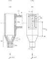
- FIG. 1 is a perspective view of the multi-mode waveguide connector 101 according to the first embodiment.
- FIG. 2A is a cross-sectional view of the multimode waveguide connector 101
- FIG. 2B is a front view of the multimode waveguide connector 101.
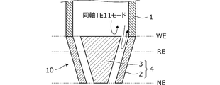
- FIG. 3 is a diagram showing how an electromagnetic wave in the coaxial TE11 mode is reflected by a tapered coaxial line.
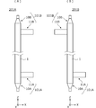
- FIG. 4A is a configuration diagram of the waveguide 201A
- FIG. 4B is a configuration diagram of the waveguide 201B.
- FIG. 5A is a diagram showing the distribution of the electromagnetic field in the TEM mode propagating through the coaxial cable.
- FIG. 5 (B) is a diagram showing the electromagnetic field distribution of the coaxial TM01 mode propagating through the port 10 for the TM01 mode
- FIG. 5 (C) is the electromagnetic field distribution of the coaxial TE11 mode blocked by the port 10 for the TM01 mode.
- FIG. 6A is a diagram showing the distribution of the electromagnetic field in the TM01 mode propagating in the circular waveguide 1
- FIG. 6B is a diagram showing the distribution of the electromagnetic field in the TE11 mode propagating in the circular waveguide 1.
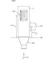
- FIG. 7 is an external view of the waveguide 202 and the multimode waveguide connectors 102A and 102B according to the second embodiment.
- FIG. 8 is a front view of the waveguide 202.
- FIG. 9 is a right side view of the waveguide 202.
- FIG. 10 is a front view of the first multimode waveguide connector 102A.
- the multi-mode waveguide connector of the present invention in order to realize MIMO with a single waveguide, as described above, after inputting the TM01 mode electromagnetic wave and the TE11 mode electromagnetic wave in the same frequency band, in the circular waveguide. Transmits while maintaining high isolation (while reducing crosstalk between modes), and separates the output while maintaining high isolation for each mode.
- a multi-mode waveguide connector is realized in which multi-mode electromagnetic waves are transmitted in a single waveguide and the electromagnetic waves of each mode are input and output with high isolation.
- this connector is realized, the electromagnetic waves of each mode exist independently even in a single waveguide.
- the procedure for realizing MIMO with one waveguide is as follows.
- a so-called single pipe made of iron having an inner diameter of 44 mm and an outer diameter of 48.6 mm is used as the circular waveguide.
- This single pipe is widely used at construction sites.
- a TM01 mode port is provided at the end of the waveguide. Further, in order to excite the TE11 mode from the side portion of the circular waveguide, a port for TE11 mode is provided on the side portion of the circular waveguide. At this time, it is necessary to prevent the input wave from the TM01 mode port from being output to the TE11 mode port. When this is output, it means that both modes are hybrid waves and not MIMO.
- the input wave from the TE11 mode port is propagated in the circular waveguide through the electric field coupling window opened in the electromagnetic wave transmission direction (axial direction) of the circular waveguide.
- the input wave from the TM01 mode port is not output from this TE11 mode port.
- a tapered coaxial line is used for the TM01 mode port, and the characteristic impedance is gradually matched from the coaxial line to the waveguide, while the TM01 mode port is ideally electric when viewed from the TE11 mode port. By acting as a wall, there is no output from the TE11 mode port to the TM01 mode port.
- a plurality of TE11 mode ports are provided in a predetermined angular relationship in the circumferential direction with the axis of the electromagnetic wave propagation direction of the circular waveguide as the rotation axis.
- the TE11 mode port is arranged at a position separated from the position serving as the electric wall of the tapered coaxial line by a predetermined distance. This reduces the influence of the reflected wave of the electromagnetic wave in the TE11 mode.
- FIG. 1 is a perspective view of the multi-mode waveguide connector 101 according to the first embodiment.
- the multi-mode waveguide connector 101 is a connector provided in the circular waveguide 1 that propagates the electromagnetic waves of the TE11 mode and the electromagnetic waves of the TM01 mode.
- the multi-mode waveguide connector 101 has a TM01 mode port 10 for inputting / outputting TM01 mode electromagnetic waves at the end of the circular waveguide 1, and a TE11 mode electromagnetic wave input / output to the side of the circular waveguide 1. It is composed of a TE11 mode port 11.
- a coaxial cable 5 is connected to the TM01 mode port 10.
- the TE11 mode port 11 includes a rectangular waveguide 6. In FIG. 1, a part of the rectangular waveguide 6 is shown.
- FIG. 2A is a cross-sectional view of the multimode waveguide connector 101
- FIG. 2B is a front view of the multimode waveguide connector 101
- FIG. 2A is a cross-sectional view taken along the line YY in FIG. 2B.
- the TM01 mode port 10 is composed of an inner conductor 3 and an outer conductor 2.
- the TM01 mode port 10 includes a coaxial connector 10C for connecting the coaxial cable 5.
- the TM01 mode port 10 is a tapered coaxial line 4 in which the inner conductor 3 extends in a tapered shape toward the inner wall surface of the circular waveguide 1 from the coaxial connector 10C to the circular waveguide 1.
- the tapered coaxial line 4 has a cutoff frequency characteristic of propagating electromagnetic waves in coaxial TM01 mode and blocking electromagnetic waves in coaxial TE11 mode.
- the TE11 mode port 11 has a coupling window 1SL that opens a part of the side surface of the circular waveguide 1.
- the coupling window 1SL is a slot-shaped opening extending in the axial direction (Z direction) of the circular waveguide 1, and is an electric field coupling window. That is, the electric field of the TE11 mode electromagnetic wave propagating through the circular waveguide 1 is directed in the Y direction.
- FIG. 5A is a diagram showing the distribution of the electromagnetic field in the TEM mode propagating through the coaxial cable.
- FIG. 5 (B) is a diagram showing the electromagnetic field distribution of the coaxial TM01 mode propagating through the port 10 for the TM01 mode
- FIG. 5 (C) is the electromagnetic field distribution of the coaxial TE11 mode blocked by the port 10 for the TM01 mode. It is a figure which shows. In these figures, the solid line shows the direction and distribution of the electric field, and the broken line shows the direction and distribution of the magnetic field.
- FIG. 6A is a diagram showing the distribution of the electromagnetic field in the TM01 mode propagating in the circular waveguide 1
- FIG. 6B is a diagram showing the distribution of the electromagnetic field in the TE11 mode propagating in the circular waveguide 1. It is a figure. In these figures, the solid line shows the direction and distribution of the electric field, and the broken line shows the direction and distribution of the magnetic field.
- the electromagnetic wave of the TEM mode propagates to the coaxial cable 5 connected to the coaxial connector 10C shown in FIG. 2 (A), and the electromagnetic wave of the coaxial TM01 mode propagates to the port 10 for the TM01 mode.
- the electromagnetic wave of the coaxial TE11 mode is blocked at the port 10 for the TM01 mode.
- the tapered coaxial line 4 is configured so as to have such a cutoff frequency characteristic. That is, the TEM mode signal propagating through the coaxial cable 5 is converted into the coaxial TM01 mode at the TM01 mode port 10, and the TM01 mode is excited to the circular waveguide 1.
- the coaxial TE11 mode has a cutoff frequency, so that the TE11 mode signal is not output from the TM01 mode port 10.
- FIG. 3 is a diagram showing how the electromagnetic wave in the coaxial TE11 mode is reflected by the tapered coaxial line 4.
- the tapered coaxial line 4 composed of the tapered inner conductor 3 and the tapered outer conductor 2 has an end WE having a large diameter and an end NE having a small diameter of the inner conductor 3.
- the tapered coaxial line 4 of the TM01 mode port 10 gradually matches the characteristic impedance from the coaxial line to the waveguide, while the TM01 mode port 10 is ideally a short-circuit plate when viewed from the TE11 mode port 11.
- the diameter of the wide end (open end) of the tapered coaxial line 4 and the diameter of the circular waveguide 1 are set to extremely close values. Since there is a gap between the inner conductor 3 and the outer conductor 2 of the tapered coaxial line 4, it is possible to excite the circular waveguide 1 in the TM01 mode.
- the tapered coaxial line 4 does not become a complete short-circuit plate (electrical wall) because the cutoff frequency of the TE11 mode decreases at the extended end WE of the inner conductor 3 and the outer conductor 2. A part of the cable does not reflect and enters the inside of the tapered coaxial line 4 as the coaxial TE11 mode. However, since the coaxial TE11 mode is cut off at a place where the inner conductor 3 and the outer conductor 2 have a small diameter to some extent, the coaxial TE11 The electromagnetic wave of the mode is reflected in one direction of the circular waveguide. If the design is made in consideration of the penetration depth, desired characteristics can be obtained.
- the electromagnetic wave in the coaxial TE11 mode propagating through the circular waveguide 1 is ideally reflected by the end WE having a large diameter of the inner conductor 3 of the tapered coaxial line 4, but in reality, this diameter is large. It is reflected by the reflecting portion RE, which is a position where the diameter is slightly smaller than that of the end portion WE in the direction of the end portion NE.
- the TM01 mode current propagating through the circular waveguide 1 flows in the axial direction (Z direction) through the tube wall of the circular waveguide 1, but the coupling window 1SL extends in the axial direction of the circular waveguide 1. Since it is short in the circumferential direction, the coupling window 1SL does not block the current in TM01 mode. That is, the coupling window 1SL does not hinder the propagation of electromagnetic waves in the TM01 mode.
- the center of the TE11 mode port 11 is formed at a position separated by ⁇ g / 2 from the reflection portion RE of the TM01 mode port 10.
- the electromagnetic wave of TE11 mode incident from the port 11 for TE11 mode propagates in the + Z direction and the ⁇ Z direction, but the electromagnetic wave of TE11 mode reflected by the reflection part RE of the port 10 for TM01 mode and the electromagnetic wave of TE11 mode propagating in the + Z direction. It is superposed in phase with the electromagnetic waves. That is, the attenuation and phase shift of the electromagnetic wave in the TE11 mode are avoided.
- the signal input from the TM01 mode port 10 propagates through the circular waveguide 1 as an electromagnetic wave in the TM01 mode, and the signal input from the TE11 mode port 11 transmits the circular waveguide 1 through the TE11.
- the waveguide is configured by providing another set of the multi-mode waveguide connector 101 shown above in the circular waveguide 1. That is, by providing the two multi-mode waveguide connectors in the circular waveguide 1, a waveguide for transmitting multi-mode electromagnetic waves is constructed.
- FIG. 4A is a configuration diagram of the waveguide 201A
- FIG. 4B is a configuration diagram of the waveguide 201B.
- the configurations of the multi-mode waveguide connectors 101A and 101B are the same as those of the multi-mode waveguide connectors 101 shown in FIGS. 1, 2 (A) and 2 (B).
- the configurations of the TM01 mode ports 10A and 10B are the same as those of the TM01 mode ports 10 shown in FIGS. 1, 2 (A) and 2 (B), and the configurations of the TE11 mode ports 11A and 11B are the same.
- FIG. 1, FIG. 2 (A), and FIG. 2 (B) are the same as the TE11 mode port 11.
- the electromagnetic wave in TE11 mode propagating through the circular waveguide 1 is input / output through the coupling window 1SL shown in FIG. 2 (B), the electromagnetic wave in TE11 mode has an electric field in the Y direction of the circular waveguide 1.
- the two TE11 mode ports 11A and 11B may be provided at positions facing the + X direction or the ⁇ X direction. That is, the TE11 mode port 11A of the first multimode waveguide connector 101A and the TE11 mode port 11B of the second multimode waveguide connector 101B have the same angle or 180 ° in the circumferential direction of the circular waveguide 1. It suffices if they are arranged in the angular relationship of.
- Second Embodiment a multi-mode waveguide connector utilizing three propagation modes will be illustrated.
- FIG. 7 is an external view of the waveguide 202 and the multimode waveguide connectors 102A and 102B according to the second embodiment.
- the waveguide 202 is composed of a circular waveguide 1, a first multi-mode waveguide connector 102A, and a second multi-mode waveguide connector 102B.
- FIG. 8 is a front view of the waveguide 202
- FIG. 9 is a right side view of the waveguide 202.
- the first multi-mode waveguide connector 102A includes a TM01 mode port 10A. Further, the first multi-mode waveguide connector 102A includes a first TE11 mode port 11A and a second TE11 mode port 12A.
- the configuration of the TM01 mode port 10A is the same as that of the TM01 mode port 10 shown in the first embodiment. Further, the configurations of the TE11 mode ports 11A and 12A are the same as those of the TE11 mode port 11 shown in the first embodiment.
- the position of the first TE11 mode port 11A with respect to the TM01 mode port 10A and the position of the second TE11 mode port 12A with respect to the TM01 mode port 10A are in the relationship shown below.
- the configuration of the first multi-mode waveguide connector 102A and the configuration of the second multi-mode waveguide connector 102B are the same. Further, the first multi-mode waveguide connector 102A and the second multi-mode waveguide connector 102B are in a positional relationship facing each other in the axial direction (Z direction) of the circular waveguide 1.
- the TE11 mode port 11A and the TE11 mode port 12A of the first multi-mode waveguide connector 102A are provided at two locations separated in the circumferential direction of the circular waveguide 1.
- the TE11 mode port 11B and the TE11 mode port 12B of the second multi-mode waveguide connector 102B are provided at two locations apart from each other in the circumferential direction of the circular waveguide 1.
- the TE11 mode port 11A of the first multimode waveguide connector 102A and the TE11 mode port 11B of the second multimode waveguide connector 102B both face the X direction. There is.
- the TE11 mode port 12A of the first multimode waveguide connector 102A and the TE11 mode port 12B of the second multimode waveguide connector 102B both face the Y direction. That is, the TE11 mode port 11A and the TE11 mode port 12A are arranged in an angular relationship of 90 ° in the circumferential direction of the circular waveguide 1. Further, the TE11 mode port 11B and the TE11 mode port 12B are arranged in an angular relationship of 90 ° in the circumferential direction of the circular waveguide 1.
- the TE11 mode port 11A and the TE11 mode port 12A are arranged orthogonally, and the TE11 mode port 11B and the TE11 mode port 12B are arranged orthogonally. Therefore, the polarization of the TE11 mode propagating the circular waveguide 1 between the ports 11A and 11B for the TE11 mode and the polarization of the TE11 mode propagating the circular waveguide 1 between the ports 12A and 12B for the TE11 mode. Are orthogonal. Therefore, high isolation between the TE11 mode ports 11A and 12A and high isolation between the TE11 mode ports 11B and 12B are realized.
- the TE11 mode electromagnetic wave incident from the TE11 mode port 11A is represented by TE11x
- the TE11x mode electromagnetic wave propagating through the circular waveguide 1 is output from the TE11 mode port 11B.
- the TE11 mode electromagnetic wave input from the TE11 mode port 12A is represented by TE11y
- the TE11y mode electromagnetic wave propagating through the circular waveguide 1 is output from the TE11 mode port 12B.
- the positional relationship between the TE11 mode port 11A of the first multimode waveguide connector 102A and the TE11 mode port 11B of the second multimode waveguide connector 102B is the same as in the example shown in FIG. 4B.
- the circular waveguide 1 may have an angular relationship of 180 ° in the circumferential direction.
- the positional relationship between the TE11 mode port 12A of the first multimode waveguide connector 102A and the TE11 mode port 12B of the second multimode waveguide 102B is also 180 ° in the circumferential direction of the circular waveguide 1. It may have an angular relationship.
- FIG. 10 is a front view of the first multi-mode waveguide connector 102A.
- the center of the TE11 mode port 11A is formed at a position separated by ⁇ g / 2 from the reflection portion RE of the TM01 mode port 10.
- the center of the TE11 mode port 12A is formed at a position separated by 3 ⁇ g / 2 from the reflection portion RE of the TM01 mode port 10A.
- FIG. 10 shows an example in which the TE11 mode port 11A and the TE11 mode port 12A have different separation distances from the TM01 mode port 10A, but the separation distances may be the same.
- FIG. 10 shows the first multi-mode waveguide connector 102A
- the second multi-mode waveguide connector 102B can be configured in the same manner.
- two TE11 mode ports are arranged in one multimode waveguide connector, but when three TE11 mode ports are arranged and a total of four modes are used, a total of four modes are used.
- three TE11 mode ports are provided around the axis (Z direction) of the circular waveguide 1 in a relationship of 120 degrees.
- each input angle is set to 360 ° / n. In these cases, isolation between TE11 modes that are not orthogonal to each other is reduced, but can be used to the extent possible in signal processing.
- the "circular waveguide” in the present invention is a waveguide in which an electromagnetic field in the circular waveguide mode is generated in the tube, and is not necessarily a perfect circle.
- the cross section on the plane orthogonal to the axis may be polygonal.
- NE End with small diameter of inner conductor WE ... End with large diameter of inner conductor RE ... Reflection 1 ... Circular waveguide 1SL ... Coupling window 2 ... Outer conductor 3 ... Inner conductor 4 ... Tapered coaxial line 5 ... Coaxial Cable 6 ... Square waveguide 10, 10A, 10B ... TM01 mode port 10C ... Coaxial connector 11, 11A, 11B, 12A, 12B ... TE11 mode port 101 ... Multi-mode waveguide connector 101A, 102A ... First multiple Mode waveguide connectors 101B, 102B ... Second multi-mode waveguide connectors 201A, 201B, 202 ... Waveguides
Abstract
[Problem] To construct a multimode waveguide connector with which it is possible to increase communication capacity using a single waveguide, and a waveguide provided with the same. [Solution] A multimode waveguide connector 101 is provided on a circular waveguide 1 that propagates electromagnetic waves of TE11 mode and electromagnetic waves of TM01 mode. The multimode waveguide connector comprises a TM01 mode port 10 disposed at an end of the circular waveguide 1 for the input and output of the electromagnetic waves of TM01 mode, and a TE11 mode port 11 disposed on the side of the circular waveguide 1 for the input and output of the electromagnetic waves of TE11 mode.
Description
本発明は、複数の伝送モードの電磁波を伝送する導波管に設けられる多モード導波管コネクタ及びそれを備える導波路に関する。
The present invention relates to a multi-mode waveguide connector provided in a waveguide that transmits electromagnetic waves in a plurality of transmission modes, and a waveguide provided with the connector.
無線機の送信機と受信機に複数のアンテナを接続し、無線区間の伝送速度を向上させる技術として、MIMO(multiple-input and multiple-output)が有効である。MIMOは帯域幅や送信出力を増大させなくても通信容量を増大できるという観点から、利用分野が拡大している。
MIMO (multiple-input and multiple-output) is effective as a technology for improving the transmission speed in the wireless section by connecting multiple antennas to the transmitter and receiver of the radio. The field of use of MIMO is expanding from the viewpoint that communication capacity can be increased without increasing bandwidth and transmission output.
例えば、3モードの光ファイバとMIMO処理により通信の高速化を図った光伝送システムが特許文献1に示されている。この光ファイバは、最低次モードのみを伝送するシングルモードファイバより径が大きく、マルチモードを伝送する。
For example, Patent Document 1 shows an optical transmission system in which communication speed is increased by using a three-mode optical fiber and MIMO processing. This optical fiber has a larger diameter than a single mode fiber that transmits only the lowest order mode, and transmits multimode.
一方、導波管を伝送路とする環境下で複数の伝送モードを利用するためには、複数の伝送モードの電磁波を伝送する導波管を構成する必要がある。しかし、そのような多モードの電磁波を伝送する導波管は従来無かった。特許文献1に示されている光伝送システムは、光波を扱う伝送システムであり、光波は光の屈折を利用するものであるので、光波とマイクロ波とでは多モードの波を合成/分離する変換器(コネクタ)の構造や設計思想は根本的に異なる。
On the other hand, in order to use a plurality of transmission modes in an environment in which a waveguide is used as a transmission path, it is necessary to configure a waveguide that transmits electromagnetic waves in a plurality of transmission modes. However, there has been no waveguide that transmits such a multi-mode electromagnetic wave. The optical transmission system shown in Patent Document 1 is a transmission system that handles light waves, and since light waves utilize refraction of light, conversion that synthesizes / separates multimode waves between light waves and microwaves. The structure and design concept of the vessel (connector) are fundamentally different.
本発明の目的は、単一の導波管を用いて通信容量を増大させることのできる多モード導波管コネクタ及びそれを備える導波路を提供することにある。
An object of the present invention is to provide a multi-mode waveguide connector capable of increasing communication capacity by using a single waveguide and a waveguide provided with the multi-mode waveguide connector.
本発明は、円形導波管内に高アイソレーションを有する複数モード伝送・合成/分離を可能とする多モード導波管コネクタ及びそれを備える導波路に関する。
The present invention relates to a multi-mode waveguide connector capable of multi-mode transmission / synthesis / separation having high isolation in a circular waveguide and a waveguide including the same.
本発明は、円形導波管に同一周波数帯であるTM01モードの電磁波及びTE11モードの電磁波を入力し、円形導波管内において高アイソレーションを保ちながら(モード間クロストークを軽減しながら)伝送させ、出力においてもモードごとに高アイソレーションを保ちながら分離する、多モード導波管コネクタ及びそれを備える導波路である。
In the present invention, the electromagnetic waves of TM01 mode and the electromagnetic waves of TE11 mode, which are in the same frequency band, are input to the circular waveguide and transmitted while maintaining high isolation (reducing crosstalk between modes) in the circular waveguide. This is a multi-mode waveguide connector and a waveguide provided with the multi-mode waveguide connector, which separates the output while maintaining high isolation for each mode.
本発明の多モード導波管コネクタは、TM01モードの電磁波及びTE11モードの電磁波を伝搬する円形導波管に設けられるコネクタであって、前記円形導波管の端部にTM01モードの電磁波を入出力するTM01モード用ポートと、前記円形導波管の側部にTE11モードの電磁波を入出力するTE11モード用ポートとで構成される。
The multi-mode waveguide connector of the present invention is a connector provided in a circular waveguide that propagates an electromagnetic wave in TM01 mode and an electromagnetic wave in TE11 mode, and receives an electromagnetic wave in TM01 mode at the end of the circular waveguide. It is composed of a TM01 mode port for output and a TE11 mode port for inputting / outputting TE11 mode electromagnetic waves to the side portion of the circular waveguide.
この構成によれば、円形導波管で複数の伝送モードの電磁波を伝送することができ、それら伝送モードの信号を複数のポートでアイソレートされた状態で入出力できる。
According to this configuration, electromagnetic waves of a plurality of transmission modes can be transmitted by a circular waveguide, and signals of those transmission modes can be input / output in a state of being isolated by a plurality of ports.
この発明によれば、単一の導波管を用いて通信容量を増大させることのできる多モード導波管コネクタ及びそれを備える導波路が得られる。
According to the present invention, a multi-mode waveguide connector capable of increasing the communication capacity by using a single waveguide and a waveguide provided with the connector can be obtained.
本発明の多モード導波管コネクタは、単一の導波管でMIMOを実現するため、前述のとおり、同一周波数帯のTM01モードの電磁波及びTE11モードの電磁波を入力後、円形導波管内においては高アイソレーションを保ちながら(モード間クロストークを軽減しながら)伝送させ、出力においてもモードごとに高アイソレーションを保ちながら分離する。
In the multi-mode waveguide connector of the present invention, in order to realize MIMO with a single waveguide, as described above, after inputting the TM01 mode electromagnetic wave and the TE11 mode electromagnetic wave in the same frequency band, in the circular waveguide. Transmits while maintaining high isolation (while reducing crosstalk between modes), and separates the output while maintaining high isolation for each mode.
単一導波管でMIMO通信を実現するには、あたかも複数のアンテナを使用しているように、単一導波管内に独立した(モード間クロストークが軽減された)伝送経路を設ける必要がある。例えば単純に導波管内に複数のモードの電磁波を入力し、出力したとしても、導波管内で混成波となるためMIMOは実現できず、低速の1ストリーム通信となってしまう。
In order to realize MIMO communication with a single waveguide, it is necessary to provide an independent transmission path (with reduced crosstalk between modes) within the single waveguide, as if using multiple antennas. be. For example, even if electromagnetic waves of a plurality of modes are simply input and output in the waveguide, MIMO cannot be realized because they are hybrid waves in the waveguide, resulting in low-speed one-stream communication.
本発明では、単一導波管内で多モードの電磁波を伝送させ、かつそれぞれのモードの電磁波を高アイソレーションで入出力する多モード導波管コネクタを実現する。本コネクタが実現した場合、単一の導波管内においても、それぞれのモードの電磁波は独立して存在する。
In the present invention, a multi-mode waveguide connector is realized in which multi-mode electromagnetic waves are transmitted in a single waveguide and the electromagnetic waves of each mode are input and output with high isolation. When this connector is realized, the electromagnetic waves of each mode exist independently even in a single waveguide.
1本の導波管でMIMOを実現するための手順は次のとおりである。
The procedure for realizing MIMO with one waveguide is as follows.
(1)一例として、円形導波管としては、内径44mm、外径48.6mmの鉄製のいわゆる単管パイプを用いる。この単管パイプは工事現場で汎用される。
(1) As an example, as the circular waveguide, a so-called single pipe made of iron having an inner diameter of 44 mm and an outer diameter of 48.6 mm is used. This single pipe is widely used at construction sites.
(2)円形導波管の端部からTM01モードを励振するため、導波管の端部にTM01モード用ポートを設ける。また、円形導波管の側部からTE11モードを励振するため、円形導波管の側部にTE11モード用ポートを設ける。このとき、TM01モード用ポートからの入力波がTE11モード用ポートへ出力されないようにする必要がある。これが出力されると、双方のモードは混成波となりMIMOとならないことを意味する。
(2) In order to excite the TM01 mode from the end of the circular waveguide, a TM01 mode port is provided at the end of the waveguide. Further, in order to excite the TE11 mode from the side portion of the circular waveguide, a port for TE11 mode is provided on the side portion of the circular waveguide. At this time, it is necessary to prevent the input wave from the TM01 mode port from being output to the TE11 mode port. When this is output, it means that both modes are hybrid waves and not MIMO.
そのため、円形導波管の電磁波伝送方向(軸方向)に開いた電界結合窓を介して、TE11モード用ポートからの入力波を円形導波管内に伝搬させる。一方、このTE11モード用ポートからはTM01モード用ポートからの入力波は出力されない。
Therefore, the input wave from the TE11 mode port is propagated in the circular waveguide through the electric field coupling window opened in the electromagnetic wave transmission direction (axial direction) of the circular waveguide. On the other hand, the input wave from the TM01 mode port is not output from this TE11 mode port.
(3)TM01モード用ポートにはテーパー同軸線路を用い、同軸線路から導波管へ徐々に特性インピーダンスの整合をとる一方、TE11モード用ポートから見て、TM01モード用ポートが理想的には電気壁として作用することで、TE11モード用ポートからTM01モード用ポートへの出力が無いようにする。
(3) A tapered coaxial line is used for the TM01 mode port, and the characteristic impedance is gradually matched from the coaxial line to the waveguide, while the TM01 mode port is ideally electric when viewed from the TE11 mode port. By acting as a wall, there is no output from the TE11 mode port to the TM01 mode port.
(4)複数のTE11モードを使用する場合、円形導波管の電磁波伝搬方向の軸を回転軸として、その周方向に所定の角度関係に複数のTE11モード用ポートを設ける。
(4) When a plurality of TE11 modes are used, a plurality of TE11 mode ports are provided in a predetermined angular relationship in the circumferential direction with the axis of the electromagnetic wave propagation direction of the circular waveguide as the rotation axis.
(5)TE11モード用ポートは、テーパー同軸線路の電気壁となる位置から所定距離離れた位置に配置する。これにより、TE11モードの電磁波の反射波の影響を低減する。
(5) The TE11 mode port is arranged at a position separated from the position serving as the electric wall of the tapered coaxial line by a predetermined distance. This reduces the influence of the reflected wave of the electromagnetic wave in the TE11 mode.
《第1の実施形態》
第1の実施形態に係る導波管アンテナおよびアンテナ装置について、図を参照して説明する。図1は第1の実施形態に係る多モード導波管コネクタ101の斜視図である。この多モード導波管コネクタ101は、TE11モードの電磁波及びTM01モードの電磁波を伝搬する円形導波管1に設けられるコネクタである。この多モード導波管コネクタ101は、円形導波管1の端部にTM01モードの電磁波を入出力するTM01モード用ポート10と、円形導波管1の側部にTE11モードの電磁波を入出力するTE11モード用ポート11とで構成される。TM01モード用ポート10には同軸ケーブル5が接続される。TE11モード用ポート11は方形導波管6を備える。図1においては方形導波管6の一部を図示している。 << First Embodiment >>
The waveguide antenna and the antenna device according to the first embodiment will be described with reference to the drawings. FIG. 1 is a perspective view of themulti-mode waveguide connector 101 according to the first embodiment. The multi-mode waveguide connector 101 is a connector provided in the circular waveguide 1 that propagates the electromagnetic waves of the TE11 mode and the electromagnetic waves of the TM01 mode. The multi-mode waveguide connector 101 has a TM01 mode port 10 for inputting / outputting TM01 mode electromagnetic waves at the end of the circular waveguide 1, and a TE11 mode electromagnetic wave input / output to the side of the circular waveguide 1. It is composed of a TE11 mode port 11. A coaxial cable 5 is connected to the TM01 mode port 10. The TE11 mode port 11 includes a rectangular waveguide 6. In FIG. 1, a part of the rectangular waveguide 6 is shown.
第1の実施形態に係る導波管アンテナおよびアンテナ装置について、図を参照して説明する。図1は第1の実施形態に係る多モード導波管コネクタ101の斜視図である。この多モード導波管コネクタ101は、TE11モードの電磁波及びTM01モードの電磁波を伝搬する円形導波管1に設けられるコネクタである。この多モード導波管コネクタ101は、円形導波管1の端部にTM01モードの電磁波を入出力するTM01モード用ポート10と、円形導波管1の側部にTE11モードの電磁波を入出力するTE11モード用ポート11とで構成される。TM01モード用ポート10には同軸ケーブル5が接続される。TE11モード用ポート11は方形導波管6を備える。図1においては方形導波管6の一部を図示している。 << First Embodiment >>
The waveguide antenna and the antenna device according to the first embodiment will be described with reference to the drawings. FIG. 1 is a perspective view of the
図2(A)は多モード導波管コネクタ101の断面図であり、図2(B)は多モード導波管コネクタ101の正面図である。図2(A)は図2(B)におけるY-Yラインでの断面図である。
FIG. 2A is a cross-sectional view of the multimode waveguide connector 101, and FIG. 2B is a front view of the multimode waveguide connector 101. FIG. 2A is a cross-sectional view taken along the line YY in FIG. 2B.
TM01モード用ポート10は、内導体3と外導体2とで構成される。このTM01モード用ポート10は同軸ケーブル5を接続する同軸コネクタ10Cを備える。また、このTM01モード用ポート10は、同軸コネクタ10Cから円形導波管1にかけて、内導体3が円形導波管1の内壁面に向かってテーパー状に拡がるテーパー同軸線路4である。このテーパー同軸線路4は同軸TM01モードの電磁波を伝搬し、同軸TE11モードの電磁波を遮断する、遮断周波数特性を有する。
The TM01 mode port 10 is composed of an inner conductor 3 and an outer conductor 2. The TM01 mode port 10 includes a coaxial connector 10C for connecting the coaxial cable 5. Further, the TM01 mode port 10 is a tapered coaxial line 4 in which the inner conductor 3 extends in a tapered shape toward the inner wall surface of the circular waveguide 1 from the coaxial connector 10C to the circular waveguide 1. The tapered coaxial line 4 has a cutoff frequency characteristic of propagating electromagnetic waves in coaxial TM01 mode and blocking electromagnetic waves in coaxial TE11 mode.
TE11モード用ポート11は、円形導波管1の側面の一部を開口する結合窓1SLを有する。この結合窓1SLは円形導波管1の軸方向(Z方向)に延びるスロット形状の開口であり、電界結合窓である。つまり、円形導波管1を伝搬するTE11モードの電磁波はY方向に電界が向く。
The TE11 mode port 11 has a coupling window 1SL that opens a part of the side surface of the circular waveguide 1. The coupling window 1SL is a slot-shaped opening extending in the axial direction (Z direction) of the circular waveguide 1, and is an electric field coupling window. That is, the electric field of the TE11 mode electromagnetic wave propagating through the circular waveguide 1 is directed in the Y direction.
図5(A)は同軸ケーブルを伝搬するTEMモードの電磁界の分布を示す図である。図5(B)はTM01モード用ポート10を伝搬する同軸TM01モードの電磁界分布を示す図であり、図5(C)は、TM01モード用ポート10では遮断される同軸TE11モードの電磁界分布を示す図である。これらの図において、実線は電界の方向及び分布、破線は磁界の方向及び分布をそれぞれ示している。
FIG. 5A is a diagram showing the distribution of the electromagnetic field in the TEM mode propagating through the coaxial cable. FIG. 5 (B) is a diagram showing the electromagnetic field distribution of the coaxial TM01 mode propagating through the port 10 for the TM01 mode, and FIG. 5 (C) is the electromagnetic field distribution of the coaxial TE11 mode blocked by the port 10 for the TM01 mode. It is a figure which shows. In these figures, the solid line shows the direction and distribution of the electric field, and the broken line shows the direction and distribution of the magnetic field.
図6(A)は円形導波管1を伝搬するTM01モードの電磁界の分布を示す図であり、図6(B)は円形導波管1を伝搬するTE11モードの電磁界の分布を示す図である。これらの図において、実線は電界の方向及び分布、破線は磁界の方向及び分布をそれぞれ示している。
FIG. 6A is a diagram showing the distribution of the electromagnetic field in the TM01 mode propagating in the circular waveguide 1, and FIG. 6B is a diagram showing the distribution of the electromagnetic field in the TE11 mode propagating in the circular waveguide 1. It is a figure. In these figures, the solid line shows the direction and distribution of the electric field, and the broken line shows the direction and distribution of the magnetic field.
図2(A)に示した同軸コネクタ10Cに接続される同軸ケーブル5には、上記TEMモードの電磁波が伝搬し、TM01モード用ポート10には同軸TM01モードの電磁波が伝搬する。しかし、このTM01モード用ポート10では同軸TE11モードの電磁波は遮断される。そのような遮断周波数特性となるように、テーパー同軸線路4は構成されている。つまり、同軸ケーブル5を伝搬するTEMモードの信号はTM01モード用ポート10で同軸TM01モードに変換され、円形導波管1へTM01モードが励振される。一方、TE11モードから見て、同軸TE11モードは遮断周波数となるため、TE11モードの信号はTM01モード用ポート10からは出力されない。
The electromagnetic wave of the TEM mode propagates to the coaxial cable 5 connected to the coaxial connector 10C shown in FIG. 2 (A), and the electromagnetic wave of the coaxial TM01 mode propagates to the port 10 for the TM01 mode. However, the electromagnetic wave of the coaxial TE11 mode is blocked at the port 10 for the TM01 mode. The tapered coaxial line 4 is configured so as to have such a cutoff frequency characteristic. That is, the TEM mode signal propagating through the coaxial cable 5 is converted into the coaxial TM01 mode at the TM01 mode port 10, and the TM01 mode is excited to the circular waveguide 1. On the other hand, when viewed from the TE11 mode, the coaxial TE11 mode has a cutoff frequency, so that the TE11 mode signal is not output from the TM01 mode port 10.
図3は上記同軸TE11モードの電磁波がテーパー同軸線路4で反射される様子を示す図である。テーパー状の内導体3及びテーパー状の外導体2で構成されるテーパー同軸線路4は、内導体3の径が大きな端部WEと小さな端部NEを有する。
FIG. 3 is a diagram showing how the electromagnetic wave in the coaxial TE11 mode is reflected by the tapered coaxial line 4. The tapered coaxial line 4 composed of the tapered inner conductor 3 and the tapered outer conductor 2 has an end WE having a large diameter and an end NE having a small diameter of the inner conductor 3.
TM01モード用ポート10のテーパー同軸線路4は、同軸線路から導波管へ徐々に特性インピーダンスの整合をとる一方、TE11モード用ポート11から見て、TM01モード用ポート10が理想的には短絡板(電気壁)として作用することで、TE11モード用ポート11からTM01モード用ポート10への出力が無いようにする。そのため、テーパー同軸線路4の広い端部(開放端)の径と、円形導波管1の径とを極めて近い値としている。テーパー同軸線路4の内導体3と外導体2との間には隙間があるため、円形導波管1へのTM01モードの励振は可能である。
The tapered coaxial line 4 of the TM01 mode port 10 gradually matches the characteristic impedance from the coaxial line to the waveguide, while the TM01 mode port 10 is ideally a short-circuit plate when viewed from the TE11 mode port 11. By acting as an (electric wall), there is no output from the TE11 mode port 11 to the TM01 mode port 10. Therefore, the diameter of the wide end (open end) of the tapered coaxial line 4 and the diameter of the circular waveguide 1 are set to extremely close values. Since there is a gap between the inner conductor 3 and the outer conductor 2 of the tapered coaxial line 4, it is possible to excite the circular waveguide 1 in the TM01 mode.
テーパー同軸線路4は、内導体3及び外導体2の拡がった端部WEにおいて、TE11モードの遮断周波数が低下するため、完全な短絡板(電気壁)とはならない。一部は反射せずテーパー同軸線路4内部に同軸TE11モードとして侵入するが、内導体3及び外導体2の径がある程度細くなる箇所で、同軸TE11モードを遮断する条件となるため、その同軸TE11モードの電磁波は円形導波管1方向へ反射される。上記侵入深さを考慮して設計すれば、所望の特性を得ることができる。
The tapered coaxial line 4 does not become a complete short-circuit plate (electrical wall) because the cutoff frequency of the TE11 mode decreases at the extended end WE of the inner conductor 3 and the outer conductor 2. A part of the cable does not reflect and enters the inside of the tapered coaxial line 4 as the coaxial TE11 mode. However, since the coaxial TE11 mode is cut off at a place where the inner conductor 3 and the outer conductor 2 have a small diameter to some extent, the coaxial TE11 The electromagnetic wave of the mode is reflected in one direction of the circular waveguide. If the design is made in consideration of the penetration depth, desired characteristics can be obtained.
つまり、円形導波管1を伝搬する同軸TE11モードの電磁波は、理想的にはテーパー同軸線路4のうち内導体3の径が大きな端部WEで反射されるが、実際にはこの径が大きな端部WEより、径が小さな端部NE方向に少し入り込んだ位置まで侵入した位置である反射部REで反射する。
That is, the electromagnetic wave in the coaxial TE11 mode propagating through the circular waveguide 1 is ideally reflected by the end WE having a large diameter of the inner conductor 3 of the tapered coaxial line 4, but in reality, this diameter is large. It is reflected by the reflecting portion RE, which is a position where the diameter is slightly smaller than that of the end portion WE in the direction of the end portion NE.
円形導波管1を伝搬するTM01モードの電流は円形導波管1の管壁を軸方向(Z方向)に流れるが、上記結合窓1SLは円形導波管1の軸方向に延びていて、周方向には短いので、結合窓1SLはTM01モードの電流を遮らない。つまり、結合窓1SLはTM01モードの電磁波の伝搬を阻害しない。
The TM01 mode current propagating through the circular waveguide 1 flows in the axial direction (Z direction) through the tube wall of the circular waveguide 1, but the coupling window 1SL extends in the axial direction of the circular waveguide 1. Since it is short in the circumferential direction, the coupling window 1SL does not block the current in TM01 mode. That is, the coupling window 1SL does not hinder the propagation of electromagnetic waves in the TM01 mode.
TE11モードの電磁波の波長をλgで表すとき、TE11モード用ポート11はTM01モード用ポート10の反射部REから、λg・n/2 (n=奇数)の位置又は当該位置の近傍に配置される。図2(B)に示した例では、TE11モード用ポート11は、その中心がTM01モード用ポート10の反射部REからλg/2だけ離れた位置に形成されている。
When the wavelength of the electromagnetic wave in the TE11 mode is represented by λg, the port 11 for the TE11 mode is arranged at the position of λg · n / 2 (n = odd number) or in the vicinity of the reflection portion RE of the port 10 for the TM01 mode. .. In the example shown in FIG. 2B, the center of the TE11 mode port 11 is formed at a position separated by λg / 2 from the reflection portion RE of the TM01 mode port 10.
TE11モード用ポート11から入射したTE11モードの電磁波は+Z方向及び-Z方向に伝搬するが、TM01モード用ポート10の反射部REで反射したTE11モードの電磁波と、+Z方向へ伝搬するTE11モードの電磁波とは同相で重ね合わされる。つまり、TE11モードの電磁波の減衰及び位相シフトが回避される。
The electromagnetic wave of TE11 mode incident from the port 11 for TE11 mode propagates in the + Z direction and the −Z direction, but the electromagnetic wave of TE11 mode reflected by the reflection part RE of the port 10 for TM01 mode and the electromagnetic wave of TE11 mode propagating in the + Z direction. It is superposed in phase with the electromagnetic waves. That is, the attenuation and phase shift of the electromagnetic wave in the TE11 mode are avoided.
以上に示した構成により、TM01モード用ポート10から入力された信号は円形導波管1をTM01モードの電磁波として伝搬し、TE11モード用ポート11から入力された信号は円形導波管1をTE11モードの電磁波として伝搬し、両ポート間のアイソレーションが確保される。
According to the configuration shown above, the signal input from the TM01 mode port 10 propagates through the circular waveguide 1 as an electromagnetic wave in the TM01 mode, and the signal input from the TE11 mode port 11 transmits the circular waveguide 1 through the TE11. Propagates as a mode electromagnetic wave, ensuring isolation between both ports.
以上に示した多モード導波管コネクタ101をもう一組、円形導波管1に設けることによって、導波路が構成される。つまり、2つの多モード導波管コネクタを円形導波管1に設けることによって、多モードの電磁波を伝送する導波路が構成される。
The waveguide is configured by providing another set of the multi-mode waveguide connector 101 shown above in the circular waveguide 1. That is, by providing the two multi-mode waveguide connectors in the circular waveguide 1, a waveguide for transmitting multi-mode electromagnetic waves is constructed.
図4(A)は導波路201Aの構成図であり、図4(B)は導波路201Bの構成図である。多モード導波管コネクタ101A,101Bの構成は、図1、図2(A)、図2(B)に示した多モード導波管コネクタ101と同じである。また、TM01モード用ポート10A,10Bの構成は、図1、図2(A)、図2(B)に示したTM01モード用ポート10と同じであり、TE11モード用ポート11A,11Bの構成は、図1、図2(A)、図2(B)に示したTE11モード用ポート11と同じである。
FIG. 4A is a configuration diagram of the waveguide 201A, and FIG. 4B is a configuration diagram of the waveguide 201B. The configurations of the multi-mode waveguide connectors 101A and 101B are the same as those of the multi-mode waveguide connectors 101 shown in FIGS. 1, 2 (A) and 2 (B). The configurations of the TM01 mode ports 10A and 10B are the same as those of the TM01 mode ports 10 shown in FIGS. 1, 2 (A) and 2 (B), and the configurations of the TE11 mode ports 11A and 11B are the same. , FIG. 1, FIG. 2 (A), and FIG. 2 (B) are the same as the TE11 mode port 11.
円形導波管1を伝搬するTE11モードの電磁波は、図2(B)に示した結合窓1SLを介して入出力されるので、TE11モードの電磁波は円形導波管1のY方向に電界が向く。したがって、2つのTE11モード用ポート11A,11Bは+X方向又は-X方向を向く位置に設けられていればよい。つまり、第1多モード導波管コネクタ101AのTE11モード用ポート11Aと第2多モード導波管コネクタ101BのTE11モード用ポート11Bとは、円形導波管1の周方向に同一角度又は180°の角度関係に配置されていればよい。
Since the electromagnetic wave in TE11 mode propagating through the circular waveguide 1 is input / output through the coupling window 1SL shown in FIG. 2 (B), the electromagnetic wave in TE11 mode has an electric field in the Y direction of the circular waveguide 1. Turn to. Therefore, the two TE11 mode ports 11A and 11B may be provided at positions facing the + X direction or the −X direction. That is, the TE11 mode port 11A of the first multimode waveguide connector 101A and the TE11 mode port 11B of the second multimode waveguide connector 101B have the same angle or 180 ° in the circumferential direction of the circular waveguide 1. It suffices if they are arranged in the angular relationship of.
《第2の実施形態》
第2の実施形態では、3つの伝搬モードを利用する多モード導波管コネクタについて例示する。 << Second Embodiment >>
In the second embodiment, a multi-mode waveguide connector utilizing three propagation modes will be illustrated.
第2の実施形態では、3つの伝搬モードを利用する多モード導波管コネクタについて例示する。 << Second Embodiment >>
In the second embodiment, a multi-mode waveguide connector utilizing three propagation modes will be illustrated.
図7は第2の実施形態に係る導波路202及び多モード導波管コネクタ102A,102Bの外観図である。導波路202は、円形導波管1、第1多モード導波管コネクタ102A及び第2多モード導波管コネクタ102Bで構成される。図8は導波路202の正面図であり、図9は導波路202の右側面図である。
FIG. 7 is an external view of the waveguide 202 and the multimode waveguide connectors 102A and 102B according to the second embodiment. The waveguide 202 is composed of a circular waveguide 1, a first multi-mode waveguide connector 102A, and a second multi-mode waveguide connector 102B. FIG. 8 is a front view of the waveguide 202, and FIG. 9 is a right side view of the waveguide 202.
第1多モード導波管コネクタ102AはTM01モード用ポート10Aを備える。また、第1多モード導波管コネクタ102Aは第1のTE11モード用ポート11A及び第2のTE11モード用ポート12Aを備える。TM01モード用ポート10Aの構成は第1の実施形態において示したTM01モード用ポート10と同じである。また、TE11モード用ポート11A,12Aの構成は第1の実施形態において示したTE11モード用ポート11と同じである。
The first multi-mode waveguide connector 102A includes a TM01 mode port 10A. Further, the first multi-mode waveguide connector 102A includes a first TE11 mode port 11A and a second TE11 mode port 12A. The configuration of the TM01 mode port 10A is the same as that of the TM01 mode port 10 shown in the first embodiment. Further, the configurations of the TE11 mode ports 11A and 12A are the same as those of the TE11 mode port 11 shown in the first embodiment.
TM01モード用ポート10Aに対する第1のTE11モード用ポート11Aの位置、及びTM01モード用ポート10Aに対する第2のTE11モード用ポート12Aの位置は後に示す関係にある。
The position of the first TE11 mode port 11A with respect to the TM01 mode port 10A and the position of the second TE11 mode port 12A with respect to the TM01 mode port 10A are in the relationship shown below.
第1多モード導波管コネクタ102Aの構成と第2多モード導波管コネクタ102Bの構成とは同じである。また、第1多モード導波管コネクタ102Aと第2多モード導波管コネクタ102Bとは、円形導波管1の軸方向(Z方向)に対して対向する位置関係にある。
The configuration of the first multi-mode waveguide connector 102A and the configuration of the second multi-mode waveguide connector 102B are the same. Further, the first multi-mode waveguide connector 102A and the second multi-mode waveguide connector 102B are in a positional relationship facing each other in the axial direction (Z direction) of the circular waveguide 1.
第1多モード導波管コネクタ102AのTE11モード用ポート11A及びTE11モード用ポート12Aは、円形導波管1の周方向に離れた2箇所に設けられている。同様に、第2多モード導波管コネクタ102BのTE11モード用ポート11B及びTE11モード用ポート12Bは、円形導波管1の周方向に離れた2箇所に設けられている。図9、図10に示す座標では、第1多モード導波管コネクタ102AのTE11モード用ポート11Aと第2多モード導波管コネクタ102BのTE11モード用ポート11BとはいずれもX方向を向いている。また、第1多モード導波管コネクタ102AのTE11モード用ポート12Aと第2多モード導波管コネクタ102BのTE11モード用ポート12BとはいずれもY方向を向いている。つまり、TE11モード用ポート11AとTE11モード用ポート12Aとは、円形導波管1の周方向で90°の角度関係で配置されている。また、TE11モード用ポート11BとTE11モード用ポート12Bとは、円形導波管1の周方向で90°の角度関係で配置されている。
The TE11 mode port 11A and the TE11 mode port 12A of the first multi-mode waveguide connector 102A are provided at two locations separated in the circumferential direction of the circular waveguide 1. Similarly, the TE11 mode port 11B and the TE11 mode port 12B of the second multi-mode waveguide connector 102B are provided at two locations apart from each other in the circumferential direction of the circular waveguide 1. At the coordinates shown in FIGS. 9 and 10, the TE11 mode port 11A of the first multimode waveguide connector 102A and the TE11 mode port 11B of the second multimode waveguide connector 102B both face the X direction. There is. Further, the TE11 mode port 12A of the first multimode waveguide connector 102A and the TE11 mode port 12B of the second multimode waveguide connector 102B both face the Y direction. That is, the TE11 mode port 11A and the TE11 mode port 12A are arranged in an angular relationship of 90 ° in the circumferential direction of the circular waveguide 1. Further, the TE11 mode port 11B and the TE11 mode port 12B are arranged in an angular relationship of 90 ° in the circumferential direction of the circular waveguide 1.
このように、TE11モード用ポート11AとTE11モード用ポート12Aとが直交して配置されていて、また、TE11モード用ポート11BとTE11モード用ポート12Bとが直交して配置されている。このため、TE11モード用ポート11A,11B間で円形導波管1を伝搬するTE11モードの偏波と、TE11モード用ポート12A,12B間で円形導波管1を伝搬するTE11モードの偏波とは直交している。そのため、TE11モード用ポート11A,12A間の高アイソレーション、及びTE11モード用ポート11B,12B間の高アイソレーションが実現される。
In this way, the TE11 mode port 11A and the TE11 mode port 12A are arranged orthogonally, and the TE11 mode port 11B and the TE11 mode port 12B are arranged orthogonally. Therefore, the polarization of the TE11 mode propagating the circular waveguide 1 between the ports 11A and 11B for the TE11 mode and the polarization of the TE11 mode propagating the circular waveguide 1 between the ports 12A and 12B for the TE11 mode. Are orthogonal. Therefore, high isolation between the TE11 mode ports 11A and 12A and high isolation between the TE11 mode ports 11B and 12B are realized.
ここで、TE11モード用ポート11Aから入射されたTE11モードの電磁波をTE11xで表すと、円形導波管1を伝搬するTE11xモードの電磁波はTE11モード用ポート11Bから出力される。同様に、TE11モード用ポート12Aから入力されたTE11モードの電磁波をTE11yで表すと、円形導波管1を伝搬するTE11yモードの電磁波はTE11モード用ポート12Bから出力される。
Here, when the TE11 mode electromagnetic wave incident from the TE11 mode port 11A is represented by TE11x, the TE11x mode electromagnetic wave propagating through the circular waveguide 1 is output from the TE11 mode port 11B. Similarly, when the TE11 mode electromagnetic wave input from the TE11 mode port 12A is represented by TE11y, the TE11y mode electromagnetic wave propagating through the circular waveguide 1 is output from the TE11 mode port 12B.
第1多モード導波管コネクタ102AのTE11モード用ポート11Aと第2多モード導波管コネクタ102BのTE11モード用ポート11Bとの位置関係は、図4(B)に示した例と同様に、円形導波管1の周方向に180°の角度関係にあってもよい。第1多モード導波管コネクタ102AのTE11モード用ポート12Aと第2多モード導波管コネクタ102BのTE11モード用ポート12Bとの位置関係についても、円形導波管1の周方向に180°の角度関係にあってもよい。
The positional relationship between the TE11 mode port 11A of the first multimode waveguide connector 102A and the TE11 mode port 11B of the second multimode waveguide connector 102B is the same as in the example shown in FIG. 4B. The circular waveguide 1 may have an angular relationship of 180 ° in the circumferential direction. The positional relationship between the TE11 mode port 12A of the first multimode waveguide connector 102A and the TE11 mode port 12B of the second multimode waveguide 102B is also 180 ° in the circumferential direction of the circular waveguide 1. It may have an angular relationship.
図10は第1多モード導波管コネクタ102Aの正面図である。図10に示す例では、TE11モード用ポート11Aは、その中心がTM01モード用ポート10の反射部REからλg/2だけ離れた位置に形成されている。また、TE11モード用ポート12Aは、その中心がTM01モード用ポート10Aの反射部REから3λg/2だけ離れた位置に形成されている。
FIG. 10 is a front view of the first multi-mode waveguide connector 102A. In the example shown in FIG. 10, the center of the TE11 mode port 11A is formed at a position separated by λg / 2 from the reflection portion RE of the TM01 mode port 10. Further, the center of the TE11 mode port 12A is formed at a position separated by 3λg / 2 from the reflection portion RE of the TM01 mode port 10A.
第1の実施形態で述べたとおり、TE11モードの電磁波の波長をλgで表すとき、TE11モード用ポート11A,12AはTM01モード用ポート10Aの反射部REから、λg・n/2 (n=奇数)の位置又は当該位置の近傍に配置されることが好ましい。
As described in the first embodiment, when the wavelength of the electromagnetic wave in the TE11 mode is represented by λg, the ports 11A and 12A for the TE11 mode are λg · n / 2 (n = odd number) from the reflection portion RE of the port 10A for the TM01 mode. ) Or near the position.
図10では、TE11モード用ポート11AとTE11モード用ポート12AのTM01モード用ポート10Aからの離間距離が異なる例を示したが、いずれの離間距離も同一であってもよい。
FIG. 10 shows an example in which the TE11 mode port 11A and the TE11 mode port 12A have different separation distances from the TM01 mode port 10A, but the separation distances may be the same.
図10では第1多モード導波管コネクタ102Aについて示したが、第2多モード導波管コネクタ102Bについても同様に構成できる。
Although FIG. 10 shows the first multi-mode waveguide connector 102A, the second multi-mode waveguide connector 102B can be configured in the same manner.
図7から図10に示した例では、1つの多モード導波管コネクタに2つのTE11モード用ポートを配置したが、TE11モード用ポートを3つ配置し、合計4つのモードを使用する場合、例えば、円形導波管1の軸(Z方向)回りに120度の関係で3つのTE11モード用ポートを設ける。同様に、n個以上のTE11モード用ポートを設ける場合、それぞれの入力角を360°/nとする。これらの場合、互いに直交しない関係のTE11モード間のアイソレーションは低減するが、信号処理上の可能な範囲で利用できる。
In the example shown in FIGS. 7 to 10, two TE11 mode ports are arranged in one multimode waveguide connector, but when three TE11 mode ports are arranged and a total of four modes are used, a total of four modes are used. For example, three TE11 mode ports are provided around the axis (Z direction) of the circular waveguide 1 in a relationship of 120 degrees. Similarly, when n or more TE11 mode ports are provided, each input angle is set to 360 ° / n. In these cases, isolation between TE11 modes that are not orthogonal to each other is reduced, but can be used to the extent possible in signal processing.
最後に、本発明は上述した実施形態に限られるものではない。当業者によって適宜変形及び変更が可能である。本発明の範囲は、上述の実施形態ではなく、特許請求の範囲によって示される。さらに、本発明の範囲には、特許請求の範囲内と均等の範囲内での実施形態からの変形及び変更が含まれる。
Finally, the present invention is not limited to the above-described embodiment. It can be appropriately modified and changed by those skilled in the art. The scope of the present invention is shown not by the above-described embodiment but by the scope of claims. Further, the scope of the present invention includes modifications and modifications from the embodiments within the scope of the claims and within the scope of the claims.
例えば、本発明においての「円形導波管」とは、管内に円形導波管モードの電磁界が生じる導波管のことであり、必ずしも真円に限らない。例えば、軸に直交する面での断面が多角形であってもよい。
For example, the "circular waveguide" in the present invention is a waveguide in which an electromagnetic field in the circular waveguide mode is generated in the tube, and is not necessarily a perfect circle. For example, the cross section on the plane orthogonal to the axis may be polygonal.
NE…内導体の径の小さな端部
WE…内導体の径の大きな端部
RE…反射部
1…円形導波管
1SL…結合窓
2…外導体
3…内導体
4…テーパー同軸線路
5…同軸ケーブル
6…方形導波管
10,10A,10B…TM01モード用ポート
10C…同軸コネクタ
11,11A,11B,12A,12B…TE11モード用ポート
101…多モード導波管コネクタ
101A,102A…第1多モード導波管コネクタ
101B,102B…第2多モード導波管コネクタ
201A,201B,202…導波路 NE ... End with small diameter of inner conductor WE ... End with large diameter of inner conductor RE ...Reflection 1 ... Circular waveguide 1SL ... Coupling window 2 ... Outer conductor 3 ... Inner conductor 4 ... Tapered coaxial line 5 ... Coaxial Cable 6 ... Square waveguide 10, 10A, 10B ... TM01 mode port 10C ... Coaxial connector 11, 11A, 11B, 12A, 12B ... TE11 mode port 101 ... Multi-mode waveguide connector 101A, 102A ... First multiple Mode waveguide connectors 101B, 102B ... Second multi-mode waveguide connectors 201A, 201B, 202 ... Waveguides
WE…内導体の径の大きな端部
RE…反射部
1…円形導波管
1SL…結合窓
2…外導体
3…内導体
4…テーパー同軸線路
5…同軸ケーブル
6…方形導波管
10,10A,10B…TM01モード用ポート
10C…同軸コネクタ
11,11A,11B,12A,12B…TE11モード用ポート
101…多モード導波管コネクタ
101A,102A…第1多モード導波管コネクタ
101B,102B…第2多モード導波管コネクタ
201A,201B,202…導波路 NE ... End with small diameter of inner conductor WE ... End with large diameter of inner conductor RE ...
Claims (10)
- TM01モードの電磁波及びTE11モードの電磁波を伝搬する円形導波管に設けられるコネクタであって、前記円形導波管の端部にTM01モードの電磁波を入出力するTM01モード用ポートと、前記円形導波管の側部にTE11モードの電磁波を入出力するTE11モード用ポートとで構成される多モード導波管コネクタ。 A connector provided in a circular waveguide that propagates an electromagnetic wave in the TM01 mode and an electromagnetic wave in the TE11 mode. A multi-mode waveguide connector consisting of a TE11 mode port that inputs and outputs TE11 mode electromagnetic waves to the side of the wave tube.
- 請求項1に記載の多モード導波管コネクタであって、前記TE11モード用ポートは、前記円形導波管の周方向に離れた2箇所に設けられた、多モード導波管コネクタ。 The multi-mode waveguide connector according to claim 1, wherein the TE11 mode ports are provided at two locations separated in the circumferential direction of the circular waveguide.
- 請求項2に記載の多モード導波管コネクタであって、前記2つのTE11モード用ポートは、前記円形導波管の周方向で90°の角度関係で配置された、多モード導波管コネクタ。 The multi-mode waveguide connector according to claim 2, wherein the two TE11 mode ports are arranged at an angle of 90 ° in the circumferential direction of the circular waveguide. ..
- 請求項1に記載の多モード導波管コネクタであって、前記TE11モード用ポートは、前記円形導波管の周方向で一定角度の関係で3箇所以上に設けられた、多モード導波管コネクタ。 The multi-mode waveguide connector according to claim 1, wherein the TE11 mode ports are provided at three or more locations in a constant angle in the circumferential direction of the circular waveguide. connector.
- 請求項1から4のいずれかに記載の多モード導波管コネクタであって、TE11モードの電磁波の波長をλgで表すとき、前記TE11モード用ポートは前記TM01モード用ポートから、λg・n/2 (n=奇数)の位置又は当該位置の近傍に配置された、多モード導波管コネクタ。 In the multi-mode waveguide connector according to any one of claims 1 to 4, when the wavelength of the electromagnetic wave in the TE11 mode is represented by λg, the TE11 mode port is λg · n / from the TM01 mode port. 2 (n = odd number) position or a multi-mode waveguide connector located near the position.
- 請求項1から5のいずれかに記載の多モード導波管コネクタであって、前記TM01モード用ポートは、内導体が前記円形導波管の内壁面に向かってテーパー状に拡がる、テーパー同軸線路であり、当該テーパー同軸線路は同軸TM01モードの電磁波を伝搬し、同軸TE11モードの電磁波は遮断する、遮断周波数特性を有する、多モード導波管コネクタ。 The multi-mode waveguide connector according to any one of claims 1 to 5, wherein the TM01 mode port is a tapered coaxial line in which an inner conductor extends in a tapered shape toward an inner wall surface of the circular waveguide. A multi-mode waveguide connector having a cutoff frequency characteristic, in which the tapered coaxial line propagates electromagnetic waves in coaxial TM01 mode and blocks electromagnetic waves in coaxial TE11 mode.
- 請求項1から6のいずれかに記載の多モード導波管コネクタであって、前記TE11モード用ポートは、前記円形導波管の側面の一部を開口する結合窓を有する多モード導波管コネクタ。 The multi-mode waveguide connector according to any one of claims 1 to 6, wherein the TE11 mode port has a coupling window that opens a part of a side surface of the circular waveguide. connector.
- 請求項7に記載の多モード導波管コネクタであって、前記結合窓は前記円形導波管におけるTE11モードの電磁波の伝搬方向に延びる形状である、多モード導波管コネクタ。 The multi-mode waveguide connector according to claim 7, wherein the coupling window has a shape extending in the propagation direction of the TE11 mode electromagnetic wave in the circular waveguide.
- 請求項1から8のいずれかに記載の多モード導波管コネクタ及び当該多モード導波管コネクタが設けられる前記円形導波管で構成される導波路であって、
前記多モード導波管コネクタは第1多モード導波管コネクタ及び第2多モード導波管コネクタで構成され、
前記円形導波管は第1端部及び第2端部を有し、
前記円形導波管の前記第1端部に前記第1多モード導波管コネクタが設けられ、前記円形導波管の前記第2端部に前記第2多モード導波管コネクタが設けられた、導波路。 A waveguide composed of the multi-mode waveguide connector according to any one of claims 1 to 8 and the circular waveguide provided with the multi-mode waveguide connector.
The multi-mode waveguide connector is composed of a first multi-mode waveguide connector and a second multi-mode waveguide connector.
The circular waveguide has a first end and a second end.
The first multi-mode waveguide connector is provided at the first end of the circular waveguide, and the second multi-mode waveguide connector is provided at the second end of the circular waveguide. , Waveguide. - 請求項9に記載の導波路であって、前記第1多モード導波管コネクタのTE11モード用ポートと前記第2多モード導波管コネクタのTE11モード用ポートとは、前記円形導波管の周方向に同一角度又は180°の角度関係に配置された、導波路。 The waveguide according to claim 9, wherein the TE11 mode port of the first multi-mode waveguide connector and the TE11 mode port of the second multi-mode waveguide connector are the circular waveguide. Waveguides arranged at the same angle or 180 ° in the circumferential direction.
Priority Applications (1)
| Application Number | Priority Date | Filing Date | Title |
|---|---|---|---|
| JP2022516895A JPWO2021215160A1 (en) | 2020-04-20 | 2021-03-19 |
Applications Claiming Priority (2)
| Application Number | Priority Date | Filing Date | Title |
|---|---|---|---|
| JP2020-074835 | 2020-04-20 | ||
| JP2020074835 | 2020-04-20 |
Publications (1)
| Publication Number | Publication Date |
|---|---|
| WO2021215160A1 true WO2021215160A1 (en) | 2021-10-28 |
Family
ID=78269368
Family Applications (1)
| Application Number | Title | Priority Date | Filing Date |
|---|---|---|---|
| PCT/JP2021/011376 WO2021215160A1 (en) | 2020-04-20 | 2021-03-19 | Multimode waveguide connector and waveguide |
Country Status (2)
| Country | Link |
|---|---|
| JP (1) | JPWO2021215160A1 (en) |
| WO (1) | WO2021215160A1 (en) |
Citations (3)
| Publication number | Priority date | Publication date | Assignee | Title |
|---|---|---|---|---|
| JPS56104201U (en) * | 1980-12-17 | 1981-08-14 | ||
| JPS6451302U (en) * | 1987-09-25 | 1989-03-30 | ||
| JP2012089998A (en) * | 2010-10-18 | 2012-05-10 | Sony Corp | Signal transmission device, electronic apparatus, and signal transmission method |
-
2021
- 2021-03-19 JP JP2022516895A patent/JPWO2021215160A1/ja active Pending
- 2021-03-19 WO PCT/JP2021/011376 patent/WO2021215160A1/en active Application Filing
Patent Citations (3)
| Publication number | Priority date | Publication date | Assignee | Title |
|---|---|---|---|---|
| JPS56104201U (en) * | 1980-12-17 | 1981-08-14 | ||
| JPS6451302U (en) * | 1987-09-25 | 1989-03-30 | ||
| JP2012089998A (en) * | 2010-10-18 | 2012-05-10 | Sony Corp | Signal transmission device, electronic apparatus, and signal transmission method |
Non-Patent Citations (1)
| Title |
|---|
| GIERULL CHRISTOPH H, LUKOWSKI TOM I: "Analysis of the Multimode Feedhorn Concept for Multi- channel SAR-GMTI", EUROPEAN CONFERENCE ON SYNTHETIC APERTURE RADAR, 1 June 2011 (2011-06-01), pages 649 - 652, XP055866677 * |
Also Published As
| Publication number | Publication date |
|---|---|
| JPWO2021215160A1 (en) | 2021-10-28 |
Similar Documents
| Publication | Publication Date | Title |
|---|---|---|
| US6661309B2 (en) | Multiple-channel feed network | |
| US5245353A (en) | Dual waveguide probes extending through back wall | |
| WO2012172565A1 (en) | Wideband waveguide turnstile junction based microwave coupler and monopulse tracking feed system | |
| US20200136220A1 (en) | Microwave Circular Polarizer | |
| US6577207B2 (en) | Dual-band electromagnetic coupler | |
| CN210926342U (en) | Broadband high-isolation dual-circularly-polarized antenna based on improved step diaphragm polarizer | |
| WO2018016632A1 (en) | Diplexer and transmitting and receiving system | |
| KR20100063698A (en) | Omt type broadband multiband transmission-reception coupler-separator for rf frequency telecommunications antennas | |
| JP2020508009A (en) | Compact bi-circularly polarized multi-band waveguide feed network | |
| US5212461A (en) | Orthomode transducer between a circular waveguide and a coaxial cable | |
| JP5600359B2 (en) | Dual-band microwave radiating element | |
| EP2600465B1 (en) | Orthomode transducer | |
| US6816026B2 (en) | Orthogonal polarization and frequency selectable waveguide using rotatable waveguide sections | |
| WO2021215160A1 (en) | Multimode waveguide connector and waveguide | |
| WO2021215161A1 (en) | Multimode waveguide antenna | |
| JPH09116302A (en) | Higher order mode coupler | |
| US3646589A (en) | Multimode tracking system utilizing a circular waveguide having slots angularly oriented with respect to the waveguide axis | |
| US6839543B1 (en) | Method and system for detecting and discriminating multipath signals | |
| JPS6014501A (en) | Polarization coupler | |
| JP3299328B2 (en) | Antenna shared circuit for circular and linear polarization | |
| CN211404690U (en) | KU wave dual-polarization waveguide | |
| JPH0722803A (en) | Polarizer/branching filter | |
| JP2803646B2 (en) | Waveguide type duplexer | |
| GB2218855A (en) | Waveguide apparatus | |
| JPH1117415A (en) | Waveguide branching filter |
Legal Events
| Date | Code | Title | Description |
|---|---|---|---|
| 121 | Ep: the epo has been informed by wipo that ep was designated in this application |
Ref document number: 21792170 Country of ref document: EP Kind code of ref document: A1 |
|
| ENP | Entry into the national phase |
Ref document number: 2022516895 Country of ref document: JP Kind code of ref document: A |
|
| NENP | Non-entry into the national phase |
Ref country code: DE |
|
| 122 | Ep: pct application non-entry in european phase |
Ref document number: 21792170 Country of ref document: EP Kind code of ref document: A1 |