WO2021214909A1 - 緩み検出センサ及びそれを用いた緩み検出方法 - Google Patents
緩み検出センサ及びそれを用いた緩み検出方法 Download PDFInfo
- Publication number
- WO2021214909A1 WO2021214909A1 PCT/JP2020/017318 JP2020017318W WO2021214909A1 WO 2021214909 A1 WO2021214909 A1 WO 2021214909A1 JP 2020017318 W JP2020017318 W JP 2020017318W WO 2021214909 A1 WO2021214909 A1 WO 2021214909A1
- Authority
- WO
- WIPO (PCT)
- Prior art keywords
- conductive layer
- detection sensor
- bolt
- looseness detection
- looseness
- Prior art date
- Legal status (The legal status is an assumption and is not a legal conclusion. Google has not performed a legal analysis and makes no representation as to the accuracy of the status listed.)
- Ceased
Links
Images







Classifications
-
- F—MECHANICAL ENGINEERING; LIGHTING; HEATING; WEAPONS; BLASTING
- F16—ENGINEERING ELEMENTS AND UNITS; GENERAL MEASURES FOR PRODUCING AND MAINTAINING EFFECTIVE FUNCTIONING OF MACHINES OR INSTALLATIONS; THERMAL INSULATION IN GENERAL
- F16B—DEVICES FOR FASTENING OR SECURING CONSTRUCTIONAL ELEMENTS OR MACHINE PARTS TOGETHER, e.g. NAILS, BOLTS, CIRCLIPS, CLAMPS, CLIPS OR WEDGES; JOINTS OR JOINTING
- F16B31/00—Screwed connections specially modified in view of tensile load; Break-bolts
-
- G—PHYSICS
- G01—MEASURING; TESTING
- G01N—INVESTIGATING OR ANALYSING MATERIALS BY DETERMINING THEIR CHEMICAL OR PHYSICAL PROPERTIES
- G01N22/00—Investigating or analysing materials by the use of microwaves or radio waves, i.e. electromagnetic waves with a wavelength of one millimetre or more
Definitions
- the present invention relates to a looseness detection sensor that detects looseness of bolts or nuts that fix parts, and a looseness detection method using the same.
- Bolts are used to tighten and fix parts to parts, and are used for various purposes from large equipment such as infrastructure structures and plant equipment to familiar products such as vehicles, playsets, and furniture.
- Bolt joints may loosen or fall off due to deterioration such as composition deformation and fatigue due to vibration or excessive force.
- Non-Patent Document 1 proposes a method of marking a bolt and monitoring the deviation of the matching mark. Further, Non-Patent Documents 2 and 3 disclose a method of detecting an abnormality by a waveguide type sensor.
- the method of monitoring the deviation of the matching mark is not suitable for inspection of parts where it is difficult to visually inspect, such as when the inspection target is in a place where it is difficult to see.
- the method of detecting anomalies with a waveguide type sensor requires painting the sensor on the structure, so if paint is applied on the bolt, it must be repainted after loosening is detected. There is a problem.
- the present invention has been made in view of this problem, and an object of the present invention is to provide a looseness detection sensor which has few construction problems and is easy to install in already constructed equipment, and a looseness detection method using the same. do.
- the looseness detection sensor is a looseness detection sensor that detects looseness of a bolt or nut that fixes a component
- the looseness detection sensor is a first type that sandwiches an insulating layer and the insulating layer from above and below.
- the gist is that the conductive layer and the second conductive layer are provided, and the shape is a washer that is sandwiched between the component and the bolt or the component and the nut without directly contacting the shaft of the bolt.
- the looseness detection method is a looseness detection method executed by the looseness detection device, in which an insulating layer and a first conductive layer and a second conductive layer sandwiching the insulating layer from above and below are formed.
- a high-frequency signal having a frequency in a predetermined range is swept and applied to a loosening detection sensor having a washer shape sandwiched between the component and the bolt or the component and the nut without directly contacting the shaft of the bolt.
- a reflected wave receiving step for receiving the reflected wave of the high frequency signal, a peak value recording step for recording the peak value of the reflected wave, and a comparison step for comparing the peak value with the past peak value to obtain the amount of change.
- the amount of change is less than the threshold value, it is determined that there is no slack, and when the amount of change is greater than or equal to the threshold value, it is determined that there is slack.
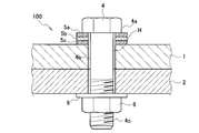
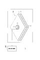
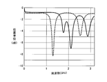
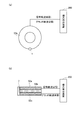
- FIG. 1 It is a perspective view which shows an example of the fixing part of a bolt using the looseness detection sensor which concerns on embodiment of this invention. It is a structural cross-sectional view along the line AA shown in FIG. It is a schematic diagram which shows the looseness detection sensor and looseness detection apparatus which concerns on 1st Embodiment of this invention. It is a figure which shows an example of the planar shape of the looseness detection sensor shown in FIG. It is a figure which shows the resonance frequency spectrum measured by using the looseness detection sensor and the looseness detection device shown in FIG. It is a block diagram which shows the functional structure example of the looseness detection apparatus shown in FIG. It is a flowchart which shows the processing procedure of the looseness detection apparatus shown in FIG.
- FIG. 1 It is a schematic diagram which shows the looseness detection sensor which concerns on 2nd Embodiment of this invention. It is a figure which shows the resonance frequency spectrum measured by using the looseness detection sensor and looseness detection apparatus shown in FIG. It is a schematic diagram which shows the looseness detection sensor which concerns on 2nd Embodiment of this invention. It is a figure which shows the resonance frequency spectrum measured by using the looseness detection sensor and looseness detection apparatus shown in FIG. It is a schematic diagram which shows the modification of the looseness detection sensor shown in FIG. It is a figure which shows the resonance frequency spectrum measured by using the looseness detection sensor and looseness detection apparatus shown in FIG.
- FIG. 1 is a perspective view showing an example of a looseness detection sensor according to the first embodiment of the present invention.
- the looseness detection sensor 5 shown in FIG. 1 is used to detect looseness of the bolt 4 and the nut that fix the two parts 1 and 2.
- parts 1 and 2 are shown as an example of a steel material.
- the structure for fixing the two parts 1 and 2 is not limited to this example.
- the looseness detection sensor 5 has a washer shape and is arranged between the component 1 and the bolt 4 or between the component 2 and the nut.
- FIG. 2 is a structural cross-sectional view taken along the line AA shown in FIG. In FIG. 2, the bolt 4, the nut 6, and the general washer 9 show their respective appearances.
- the looseness detection sensor 5 is arranged, for example, on the neck portion 4a side of the bolt 4. Alternatively, it may be arranged on the nut 6 side. Further, it may be arranged on both the neck portion 4a side and the nut 6 side.
- the looseness detection sensor 5 has a three-layer structure in which the insulating layer 5b is sandwiched between the first conductive layer 5a and the second conductive layer 5c. Further, the looseness detection sensor 5 has a washer shape that is sandwiched between the component 1 and the bolt 4 or the component 2 and the nut 6 without directly contacting the shaft 4b of the bolt 4.
- the size of the hole in the center of the washer shape is larger than the diameter of the shaft 4b of the bolt 4 for which looseness is to be detected, and the neck portion 4a and the first conductive layer 5a of the bolt 4 and the second conductive layer 5c and the component 1 Are electrically connected to each other.
- the shape is such that the shaft 4b of the bolt 4 and the screw portion 4c do not come into direct contact with each other.
- the first and second conductive layers 5a and 5c are made of the same material as a general washer.
- stainless steel materials such as SUS304,310,316 and vapor depositions of those metals are used.
- an elastic resin such as PTFE or PTE is used.
- a material other than resin such as oxide or glass may be used.
- FIG. 3 is a schematic view showing the looseness detection sensor 5 looseness detection device 200 according to the present embodiment.
- FIG. 4 is a diagram showing an example of the planar shape of the looseness detection sensor 5.
- the looseness detection device 200 sweeps and applies a high frequency signal having a frequency in a predetermined range to the first conductive layer 5a, and detects the resonance frequency (natural frequency) of the looseness detection sensor 5.
- the resonance wavelength ⁇ 1 of the looseness detection sensor 5 can be expressed by the following equation.
- the resonance wavelength ⁇ 1 is the wavelength of the first-order natural frequency.
- the resonance wavelength ⁇ 1 is a wavelength of a high frequency signal confined in the insulating layer 5b of the looseness detection sensor 5. Therefore, the resonance wavelength ⁇ 1 differs depending on the material of the insulation increase 5b.
- L is the length of a half circumference of a circle passing through the center of the ring width W of the washer shape.
- n is an integer greater than or equal to 1.
- the resonance frequency f changes depending on how the bolt 4 is tightened.
- the resonance frequency of the looseness detection sensor 5 alone (Equation (1)).
- the inner peripheral portion of the looseness detection sensor 5 is short-circuited by the head of the bolt 4, so that the electric field strength of the inner peripheral portion is lowered. Therefore, the propagation mode of the high-frequency signal changes, and the resonance wavelength ⁇ 1 represented by the equation (1) becomes shorter. In this way, the looseness of the bolt 4 can be detected based on the change in the resonance frequency. It is also possible to detect looseness of the bolt 4 depending on the presence or absence of the resonance frequency.
- FIG. 5 shows an example of a change in the resonance frequency detected by using the looseness detection sensor 5 manufactured for the bolt 4 of the M30.
- the horizontal axis of FIG. 3 is the frequency (GHz), and the vertical axis is the arbitrary unit (dB).
- the solid line shows the resonance frequency when the bolt 4 is tightened
- the broken line shows the resonance frequency when the bolt 4 is loosened.
- the resonance frequency of about 2.1 GHz changes to about 1.4 GHz when the bolt 4 is loosened.
- the resonance frequency of about 2.9GHZ changes to about 2.5GHZ when the bolt 4 is loosened.
- the looseness detection sensor 5 is excellent in workability because it has a washer shape sandwiched between bolts 4 or nuts 6. In addition, since the shape is annular, the risk of injuring the operator is low and the safety is high.
- FIG. 6 is a block diagram showing a functional configuration example of the looseness detection device 200 according to the embodiment of the present invention. A flowchart showing the processing procedure is shown in FIG.
- the looseness detection device 200 includes a frequency sweep unit 20, a high frequency application unit 21, a vibration mode detection unit 22, a vibration mode recording unit 23, a determination unit 24, and a control unit 25.
- the control unit 25 is a function configuration unit that controls the operation of each function configuration unit, and can be configured by, for example, a computer including a ROM, a RAM, a CPU, and the like.
- a part of the vibration mode detection unit 22, the vibration mode recording unit 23, and the determination unit 24 can also be configured by the computer.
- the looseness detection device 200 inputs a high frequency signal to the first conductive layer 5a of the looseness detection sensor 5.
- the frequency sweeping unit 20 sweeps frequencies in a predetermined range.
- the high frequency application unit 21 generates a high frequency signal having a frequency swept by the frequency sweep unit 20 and applies it to the first conductive layer 5a of the looseness detection sensor 5 (step S1).
- the vibration mode detection unit 22 detects the vibration mode of the looseness detection sensor 5 (step S2).
- the vibration mode can be obtained, for example, by performing a fast Fourier (FFT) transform on the characteristics of the current input to the first conductive layer 5a.
- FFT fast Fourier
- the reflected wave reflected from the first conductive layer 5a may be fast Fourier transformed to detect the vibration mode.
- the vibration mode detection unit 22 is connected in series between the conductive film 7 and the vibration mode recording unit 23 (not shown). Specific examples of the vibration mode will be described later.
- the vibration mode recording unit 23 records the peak value of the vibration detected by the vibration mode detection unit 22 (step S3).
- the peak value of vibration can be obtained, for example, by the maximum value of the current input from the first conductive layer 5a.
- the peak value can be expressed by, for example, a current value and a frequency through which the current flows.
- the determination unit 24 compares the obtained peak value with the peak value obtained in the past and obtains the amount of change (step S4).
- the amount of change may be, for example, a current value and a frequency, or may be only a frequency.
- the determination unit 24 determines that there is no slack when the amount of change is less than the threshold value (step S6), and determines that there is slack when the amount of change is greater than or equal to the threshold value (step S7).
- step S6 determines that there is no slack when the amount of change is less than the threshold value
- step S7 determines that there is slack when the amount of change is greater than or equal to the threshold value
- the looseness detection method executed by the looseness detection device 200 is the looseness detection method executed by the looseness detection device 200, and the insulating layer 5b and the insulating layer 5b are mounted from above and below.
- a looseness detection sensor 5 having a first conductive layer 5a and a second conductive layer 5c to be sandwiched, and having a washer shape sandwiched between the component 1 and the bolt 4 or the component 2 and the nut 6 without directly contacting the shaft 4b of the bolt 4.
- step S2 in which a high frequency signal having a frequency in a predetermined range is swept and applied (step S1) and the reflected wave of the high frequency signal is received.
- looseness may be detected based on the mode in which the peak value occurs.
- the aspect means that the frequency interval indicating the peak value changes from, for example, a non-uniform state to a uniform state.
- FIG. 8 is a diagram showing a looseness detection sensor according to a second embodiment of the present invention.
- FIG. 8A is a plan view, and FIG. 8A schematically shows a cross section thereof.
- the first conductive layer 52a, the insulating layer 52b, and the second conductive layer 52c are annular, and have a feeding point for feeding a high frequency signal to the first conductive layer 52a or the second conductive layer 52c.
- One point of the first conductive layer 52a and the second conductive layer 52c on the opposite side of the feeding point is short-circuited by the conductive member 7.
- m is an odd number.
- the resonance wavelength ⁇ resonates on the short wavelength side according to the following equation, unlike the case of the first embodiment. Can be done.
- n 2n + 1.
- n is an integer of 1 or more
- m is an odd number of 3 or more. Therefore, the relationship between the resonance wavelength ⁇ 2 and the resonance circumferential wavelength ⁇ 1 can be expressed by the following equation.
- this embodiment can improve the degree of freedom in design.
- FIG. 9 shows an example of a change in the resonance frequency detected by using the looseness detection sensor 52 manufactured for the bolt 4 of the M30.
- the horizontal axis of FIG. 9 is the frequency (GHz), and the vertical axis is the arbitrary unit (dB).
- the ring-shaped sensor resonates at the length of half the circumference of the ring, but when short-circuited at a position opposite to the feeding point with respect to the center of the sensor, the bolt 4 is loosened and shown in equation (2). There is a resonant wavelength. Further, since the end portion having a half circumference of the ring is forcibly short-circuited, the wavelength of each resonance shifts to the short wavelength side according to the equation (4).
- the resonance frequency shown in the equation (2) is used for loosening detection, the resonance frequency can be lowered. Further, by utilizing the feature represented by the equation (3), it is possible to detect on the higher frequency side than the looseness detection sensor 5.
- the position where the first conductive layer 52a and the second conductive layer 52c are short-circuited in the conductive member 7 may be any position in the annular shape. That is, one point of the first conductive layer 52a and the second conductive layer 52c at a position different from the feeding point for feeding the high frequency signal to the first conductive layer 52a or the second conductive layer 52c may be short-circuited by the conductive member 7. .. As a result, the degree of freedom in designing the looseness detection sensor can be increased.
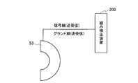
- FIG. 10 is a diagram showing a looseness detection sensor according to a third embodiment of the present invention.
- the looseness detection sensor 53 shown in FIG. 10 has an insulating layer 53b (not shown) and a first conductive layer 53a and a second conductive layer 53c (not shown), similarly to the looseness detection sensors 5 and 52 described above. It has a three-layer structure that sandwiches it.
- the resonance wavelength ⁇ appears according to the following equation.
- n is an integer.
- the looseness of the bolt 4 can be detected based on the wavelength of the resonance frequency. It is also possible to detect looseness of the bolt 4 depending on the presence or absence of the resonance frequency.
- FIG. 11 is a diagram showing a change in the resonance frequency when the looseness detection sensor 53 detects the looseness of the bolt 4.
- the horizontal axis of FIG. 11 is the frequency (GHz), and the vertical axis is the arbitrary unit (dB).
- the resonance wavelength ⁇ of the sensor appears according to the equation (5) depending on the length L.
- the sensor is closed, a resonance mode in which the electric field strength on the inner circumference of the sensor is reduced is formed, and the resonance frequency shifts to the high frequency side.
- the looseness detection sensor 53 of the third embodiment is not limited to the planar shape shown in FIG. For example, it may be semi-circular as shown in FIG.
- FIG. 13 is a diagram showing a change in the resonance frequency when the looseness detection sensor 53 detects the looseness of the bolt 4.
- the relationship between the horizontal axis and the vertical axis is the same as in FIG. 11 and the like.
- the looseness detection sensor 53 may have a flat shape that can be inserted under the bolt 4 or the nut 6.
- each of the insulating layer 53b, the first conductive layer 53a, and the second conductive layer 53c has a planar shape that can be inserted under the bolt 4 or the nut 6 from a direction orthogonal to the axis 4b of the bolt 4.
- the looseness detection sensor 53 can be arranged without removing the installed bolt 4.
- the two parts are sandwiched between the fixed portions.
- Looseness detection Based on the change in the natural frequency of the sensors 5, 52, 53, the looseness of the bolt 4 or nut 6 that fixes the portion is detected. Therefore, it is also suitable for inspection of a place where the inspection target is difficult to see or a part where visual inspection is difficult at a distance.
- the looseness detection sensor 5 and the looseness detection device 200 may be connected by a high frequency signal line such as a micro split line. Further, it may be connected by a waveguide or the like.
- a loosening detection device 200 may be arranged in the vicinity of the bolt 4 at a key part of the structure so that the detection result can be transmitted wirelessly. By doing so, the risk associated with the inspection can be eliminated. It is also possible to reduce the inspection cost.
- the looseness detection sensors 5, 52, 53 of the present invention are not limited to the above-described first to third embodiments. It can be widely applied to a structure in which two parts 1 and 2 are fixed by bolts 4. Further, when the surface of the component 1 has conductivity, the second conductive layer 5c may be omitted.
- the present invention is not limited to the above embodiment, and can be modified within the scope of the gist thereof.
Landscapes
- Physics & Mathematics (AREA)
- General Engineering & Computer Science (AREA)
- Engineering & Computer Science (AREA)
- Analytical Chemistry (AREA)
- Electromagnetism (AREA)
- Health & Medical Sciences (AREA)
- Life Sciences & Earth Sciences (AREA)
- Chemical & Material Sciences (AREA)
- Mechanical Engineering (AREA)
- Biochemistry (AREA)
- General Health & Medical Sciences (AREA)
- General Physics & Mathematics (AREA)
- Immunology (AREA)
- Pathology (AREA)
- Testing Of Devices, Machine Parts, Or Other Structures Thereof (AREA)
- Measurement Of Length, Angles, Or The Like Using Electric Or Magnetic Means (AREA)
Abstract
部品1,2を固定するボルト4又はナット6の緩みを検出する緩み検出センサ5であって、緩み検出センサ5は、絶縁層5bと、当該絶縁層5bを上下から挟む第1導電層5aと第2導電層5bとを備え、ボルト4の軸4bとは直接接触せずに部品1とボルト4又は部品2とナット6で挟まれる座金形状である。
Description
本発明は、部品を固定するボルト又はナットの緩みを検出する緩み検出センサ及びそれを用いた緩み検出方法に関する。
ボルトは、部品と部品を締め付け、固定するものであり、インフラ構造物、プラント設備等の大型設備から、乗り物、遊具、及び家具等の身近な製品まで様々な用途で使用される。ボルトの接合部では、振動や過大な力による組成変形、疲労等の劣化が原因で、緩みや脱落が生じることがある。
これらが原因で、例えば橋梁の崩落事故、接合部分からのガス及び液体の漏洩、遊具の破損、高所からの落下物による人身事故等が発生する。これらの事故を防止するため、例えば非特許文献1にボルトにマーキングをして、合いマークのズレを監視する方法が提案されている。また、非特許文献2と3に導波路型センサによって異常を検出する方法が開示されている。
構造物のゆるみ対策、〔令和2年4月13日検索〕、インターネット(https://www.euroke.co.jp/linecap1/)
E. Matsunaga ; M. Nakamura ; T. Minotani ; M. Tsuda, "Paintable Wireless Passive Sensor based on Electromagnetic Waveguide to Detect Loose Bolts for Remote Infrastructure Inspection." Proc. IEEE SENSORS 2019, Montreal, QC, Canada, Canada,2019.
E. Matsunaga, T. Minotani, S. Oka, and M. Tsuda, "Fundamental study of coating-type sensor for detection of infrastructure deterioration. "Proceedings of the 65th Japan Conference on Materials and Environments, Japan, pp. 178-181, 2019 (in Japanese).
しかしながら、合いマークのズレを監視する方法等は、検査対象が見難い場所にある場合、又は遠方などの目視点検が困難な部分の検査には適さない。また、導波路型センサによる異常を検出する方法は、構造物にセンサを塗装する必要があるため、ボルトの上に塗料を塗装した場合は、緩み検知後に再塗装しなくてはならないといった施工上の課題がある。また、施工済みの既存の設備へのセンサの設置が難しいと言った課題がある。
本発明は、この課題に鑑みてなされたものであり、施工上の課題が少なく、施工済みの設備への設置が容易な緩み検出センサ及びそれを用いた緩み検出方法を提供することを目的とする。
本発明の一態様に係る緩み検出センサは、部品を固定するボルト又はナットの緩みを検出する緩み検出センサであって、前記緩み検出センサは、絶縁層と、該絶縁層を上下から挟む第1導電層と第2導電層とを備え、前記ボルトの軸とは直接接触せずに前記部品とボルト又は前記部品とナットで挟まれる座金形状であることを要旨とする。
また、本発明の一態様に係る緩み検出方法は、上記緩み検出装置が実行する緩み検出方法であって、絶縁層と、該絶縁層を上下から挟む第1導電層と第2導電層とを備え、前記ボルトの軸とは直接接触せずに前記部品と前記ボルト又は前記部品と前記ナットで挟まれる座金形状である緩み検出センサに、所定の範囲の周波数の高周波信号を掃引して印加し、該高周波信号の反射波を受信する反射波受信ステップと、前記反射波のピーク値を記録するピーク値記録ステップと、前記ピーク値と過去の前記ピーク値とを比較し変化量を求める比較ステップと、前記変化量が閾値未満の場合は前記緩みがないと判定し、前記変化量が閾値以上の場合は前記緩みがあると判定する判定ステップとを行うことを要旨とする。
本発明によれば、施工上の課題が少なく、施工済みの設備への設置が容易な緩み検出センサ及びそれを用いた緩み検出方法を提供することができる。
以下、本発明の実施形態について図面を用いて説明する。複数の図面中同一のものには同じ参照符号を付し、説明は繰り返さない。
〔第1実施形態〕
図1は、本発明の第1実施形態に係る緩み検出センサの一例を示す斜視図である。図1に示す緩み検出センサ5は、二つの部品1,2を固定するボルト4とナットの緩みを検出するのに用いられる。
図1は、本発明の第1実施形態に係る緩み検出センサの一例を示す斜視図である。図1に示す緩み検出センサ5は、二つの部品1,2を固定するボルト4とナットの緩みを検出するのに用いられる。
図1に示す例は、部品1,2を鋼材の例で示す。二つの部品1,2を固定する構造は、この例に限定されない。ボルト4は複数で有っても良い。緩み検出センサ5は座金形状であり、部品1とボルト4、又は、部品2とナットの間に配置される。
図2は、図1に示すA-A線に沿う構造断面図である。図2において、ボルト4、ナット6、及び一般的なワッシャー9はそれぞれの外観を示す。
図2に示すように、緩み検出センサ5は、例えばボルト4の首部4a側に配置される。又は、ナット6側に配置してもよい。また、首部4a側とナット6側の両方に配置しても構わない。
緩み検出センサ5は、絶縁層5bを、第1導電層5aと第2導電層5cとで挟む三層構造である。また、緩み検出センサ5は、ボルト4の軸4bとは直接接触せずに部品1とボルト4又は部品2とナット6で挟まれる座金形状である。
座金形状の中央の穴の大きさは、緩みを検出したいボルト4の軸4bの直径以上の大きさであり、ボルト4の首部4aと第1導電層5a、及び第2導電層5cと部品1は、それぞれ電気的に接続する。一方、ボルト4の軸4bとネジ部4cには直接接触しない形状である。
第1・第2導電層5a,5cは、一般的な座金(ワッシャー)と同じ材料で構成される。例えば、SUS304,310,316等のステンレス材料及びそれらの金属の蒸着物を用いる。
絶縁層5bは、例えば、PTFE,PTE等の弾力性のある樹脂を用いる。又は、酸化物やガラス等の樹脂以外の材料を用いてもよい。
図3は、本実施形態に係る緩み検出センサ5緩み検出装置200を示す模式図である。図4は、緩み検出センサ5の平面形状の一例を示す図である。
緩み検出装置200は、第1導電層5aに、所定の範囲の周波数の高周波信号を掃引して印加し、緩み検出センサ5の共振周波数(固有振動数)を検出する。緩み検出センサ5の共振波長λ1は次式で表せる。共振波長λ1は、1次の固有振動数の波長である。

共振波長λ1は、緩み検出センサ5の絶縁層5bに閉じ込められる高周波信号の波長である。よって、共振波長λ1は絶縁増5bの材料によって異なる。ここでLは、座金形状のリング幅Wの中央を通る円の半周の長さである。nは1以上の整数である。
共振周波数fは、ボルト4の締め付け具合で変化する。ボルト4が緩んでいる状態では緩み検出センサ5単体の共振周波数と同じである(式(1))。一方、ボルト4が締め付けられた状態では、緩み検出センサ5の内周部分がボルト4の頭部によってショートするので内周部分の電界強度が下がる。そのため、高周波信号の伝搬モードが変化し、式(1)で表される共振波長λ1が短くなる。このように、共振周波数の変化に基づいてボルト4の緩みを検出することができる。また、共振周波数の有無でボルト4の緩みを検出することもできる。
図5は、M30のボルト4用に作製した緩み検出センサ5を使用して検出した共振周波数の変化例を示す。図3の横軸は周波数(GHz)、縦軸は任意単位(dB)である。
図5において、実線はボルト4が締まった状態、破線はボルト4が緩んだ状態の共振周波数を示す。約2.1GHzの共振周波数は、ボルト4が緩むことで約1.4GHZに変化する。また、約2.9GHZの共振周波数は、ボルト4が緩むことで約2.5GHZに変化する。
このように、共振周波数の変化でボルト4の緩みを検出することができる。本実施形態に係る緩み検出センサ5は、ボルト4又はナット6で挟まれる座金形状であるため施工性に優れる。また、形状が円環状であるため作業者を傷つけるリスクが低く安全性が高い。
次に、本発明の実施形態に係る緩み検出装置について説明する。
(緩み検出装置)
図6は、本発明の実施形態に係る緩み検出装置200の機能構成例を示すブロック図である。その処理手順を示すフローチャートを図7に示す。
図6は、本発明の実施形態に係る緩み検出装置200の機能構成例を示すブロック図である。その処理手順を示すフローチャートを図7に示す。
緩み検出装置200は、周波数掃引部20、高周波印加部21、振動モード検出部22、振動モード記録部23、判定部24,及び制御部25を備える。制御部25は、各機能構成部の動作を制御する機能構成部であり、例えば、ROM、RAM、CPU等からなるコンピュータで構成することができる。制御部25をコンピュータで実現する場合は、振動モード検出部22の一部、振動モード記録部23、及び判定部24もそのコンピュータで構成することが可能である。
緩み検出装置200は、緩み検出センサ5の第1導電層5aに高周波信号を入力する。周波数掃引部20は、所定の範囲の周波数を掃引する。高周波印加部21は、周波数掃引部20が掃引する周波数の高周波信号を生成し、緩み検出センサ5の第1導電層5aに印加する(ステップS1)。
振動モード検出部22は、緩み検出センサ5の振動モードを検出する(ステップS2)。振動モードは、例えば、第1導電層5aに入力される電流の特性を高速フーリエ(FFT)変換することで求めることができる。
又は、第1導電層5aから反射される反射波を高速フーリエ変換して振動モードを検出するようにしても良い。反射波から検出する場合は、振動モード検出部22は、導電性膜7と振動モード記録部23との間に直列に接続される(図示せず)。振動モードの具体例は後述する。
振動モード記録部23は、振動モード検出部22で検出された振動のピーク値を記録する(ステップS3)。振動のピーク値は、例えば第1導電層5aから入力される電流の最大値で求めることができる。ピーク値は、例えば電流値と、その電流が流れる周波数とで表せる。
判定部24は、まず、得られたピーク値と過去に得られたピーク値とを比較し変化量を求める(ステップS4)。変化量は、例えば電流値と、周波数でも良いし、周波数だけでも良い。
そして、判定部24は、変化量が閾値未満の場合は緩みがないと判定し(ステップS6)、変化量が閾値以上の場合は緩みがあると判定する(ステップS7)。緩みの判定の具体例は後述する。
以上説明したように本実施形態に係る緩み検出装置200が実行する緩み検出方法は、上記の緩み検出装置200が実行する緩み検出方法であって、絶縁層5bと、当該絶縁層5bを上下から挟む第1導電層5aと第2導電層5cとを備え、ボルト4の軸4bとは直接接触せずに部品1とボルト4又は部品2とナット6で挟まれる座金形状である緩み検出センサ5に、所定の範囲の周波数の高周波信号を掃引して印加(ステップS1)し、該高周波信号の反射波を受信する反射波受信ステップ(ステップS2)と、
前記反射波のピーク値を記録するピーク値記録ステップ(ステップS3)と、
前記ピーク値と過去の前記ピーク値とを比較し変化量を求める比較ステップ(ステップS4)と、
前記変化量が閾値未満の場合は前記緩みがないと判定(ステップS6)し、前記変化量が閾値以上の場合は前記緩みがある(ステップS7)と判定する判定ステップ(ステップS5)とを行う。これにより、ボルト4による二つの部品1,2の締め付け部分の緩みを検出することができる。
前記反射波のピーク値を記録するピーク値記録ステップ(ステップS3)と、
前記ピーク値と過去の前記ピーク値とを比較し変化量を求める比較ステップ(ステップS4)と、
前記変化量が閾値未満の場合は前記緩みがないと判定(ステップS6)し、前記変化量が閾値以上の場合は前記緩みがある(ステップS7)と判定する判定ステップ(ステップS5)とを行う。これにより、ボルト4による二つの部品1,2の締め付け部分の緩みを検出することができる。
なお、緩みの検出は、ピーク値が生じる態様に基づいて検出するようにしてもよい。態様とは、ピーク値を示す周波数の間隔が、例えば不均一な状態から均一な状態に変化する等のことである。
〔第2実施形態〕
図8は、本発明の第2実施形態に係る緩み検出センサを示す図である。図8(a)は平面図、図8(a)はその断面を模式的に示す。
図8は、本発明の第2実施形態に係る緩み検出センサを示す図である。図8(a)は平面図、図8(a)はその断面を模式的に示す。
図8に示すように、第1導電層52a、絶縁層52b、及び第2導電層52cは円環状であり、第1導電層52a又は第2導電層52cに高周波信号を給電する給電点と、該給電点と反対側の第1導電層52aと第2導電層52cの一点が導電性部材7で短絡されている。
本実施形態に係る緩み検出センサ52の共振波長λ2と座金形状のリング幅Wの中央を通る円の半周の長さLとの関係は次式で表せる。

ここで、mは奇数である。ボルト4が締まった状態における最も低い共振条件はm=1の場合である。また、円環の半周の長さで第1導電層52aと第2導電層52cが短絡されているため、共振波長λは第1実施形態の場合と異なり次式に従って短波長側で共振することができる。

ここでm=2n+1である。nは1以上の整数、mは3以上の奇数である。ゆえに共振波長λ2と共振周波長λ1の関係は次式で表せる。

式(4)に示すように、第1実施形態に対して短波長側で共振することができる。したがって、本実施形態は設計の自由度を向上させることができる。
図9は、M30のボルト4用に作製した緩み検出センサ52を使用して検出した共振周波数の変化例を示す。図9の横軸は周波数(GHz)、縦軸は任意単位(dB)である。
リング状のセンサはリングの半周の長さで共振しているが、センサ中央に対して給電点と反対側の位置においてショートさせた場合、ボルト4が緩んだ状態において、式(2)に示す共振波長が存在する。また、リングの半周の長さの端部が強制的に短絡されているため、各共振の波長は式(4)に従って短波長側にシフトする。
式(2)に示す共振周波数を緩み検出に利用すれば、共振周波数を低周波数化することができる。また、式(3)に示す特徴を利用すれば、緩み検出センサ5よりも高周波側での検出が可能となる。
なお、導電性部材7で第1導電層52aと第2導電層52cを短絡させる位置は、円環状のどの位置であっても構わない。つまり、第1導電層52a又は第2導電層52cに高周波信号を給電する給電点と異なる位置の第1導電層52aと第2導電層52cの一点が導電性部材7で短絡されていればよい。これにより、緩み検出センサの設計の自由度を高めることができる。
{第3実施形態}
図10は、本発明の第3実施形態に係る緩み検出センサを示す図である。図10に示す緩み検出センサ53は、上記の緩み検出センサ5,52と同様に、絶縁層53b(図示せず)を、第1導電層53aと第2導電層53c(図示)せず)を挟み込む三層構造である。
図10は、本発明の第3実施形態に係る緩み検出センサを示す図である。図10に示す緩み検出センサ53は、上記の緩み検出センサ5,52と同様に、絶縁層53b(図示せず)を、第1導電層53aと第2導電層53c(図示)せず)を挟み込む三層構造である。
本実施形態に係る緩み検出センサ53は、ボルト4が緩んでいる場合、共振波長λは次式に従って現れる。

ここでnは整数である。
一方、ボルト4が締まっている場合、緩み検出センサ5の内周部分の電界強度が下がるため高周波信号の伝搬モードが変化し、式(5)で表される共振波長λが短くなる。このように、共振周波数の波長に基づいてボルト4の緩みを検出することができる。また、共振周波数の有無でボルト4の緩みを検出することもできる。
図11は、緩み検出センサ53でボルト4の緩みを検出した共振周波数の変化を示す図である。図11の横軸は周波数(GHz)、縦軸は任意単位(dB)である。
ボルト4が緩んでいる場合は、センサの共振波長λは、長さLに依存して式(5)に従って現れる。一方、センサが締まっている場合は、センサの内周の電界強度が低下した共振モードが形成されて共振周波数が高周波側にシフトする。
なお、第3実施形態の緩み検出センサ53は、図10に示す平面形状に限られない。例えば、図12に示すように半円形であっても構わない。
図13は、緩み検出センサ53でボルト4の緩みを検出した共振周波数の変化を示す図である。横軸と縦軸の関係は図11等と同じである。
図13に示すように、ボルト4が緩む(破線)と、共振周波数は凡そ等間隔(式(5))に変化する。
本実施形態に係る緩み検出センサ53は、ボルト4又はナット6の下に挿入な能な平面形状であればよい。要するに、絶縁層53b、第1導電層53a、及び第2導電層53cのそれぞれは、ボルト4の軸4bと直交する方向からボルト4又はナット6の下に挿入可能な平面形状である。これにより、施工済みのボルト4を取り外すことなく緩み検出センサ53を配置することができる。
以上述べたように、本実施形態に係る緩み検出センサ5,52,53、及び緩み検出センサ5と緩み検出装置200を用いた緩み検出方法によれば、2つの部品の固定部分に挟まれた緩み検出センサ5,52,53の固有振動数の変化に基づいて、当該部分を固定するボルト4又はナット6の緩みを検出する。よって、検査対象が見難い場所、又は、遠方で目視点検が困難な部分の検査にも好適である。
また、緩み検出センサ5,52,53と緩み検出装置200を、離して配置すれば遠隔でボルトの緩みを検出することができる。緩み検出センサ5と緩み検出装置200の間は、マイクロスプリットライン等の高周波信号線で接続すれば良い。また、導波管等で接続するようにしても良い。
また、構造上の要の部分のボルト4の近傍に緩み検出装置200を配置して、検出結果を無線で送信するようにしても良い。そうすることで、検査に伴う危険性を排除することが出来る。また、検査コストを削減することも可能である。
なお、本発明の緩み検出センサ5,52,53は、上記の実施形態1~3に限定されない。2つの部品1,2をボルト4で固定する構造に広く適用することが可能である。また、部品1の表面が導電性を持つ場合は、第2導電層5cは無くても構わない。
このように本発明は、上記の実施形態に限定されるものではなく、その要旨の範囲内で変形が可能である。
1,2:部品
4:ボルト
4a:首部
4b:軸
4c:ネジ部
5:緩み検出センサ
5a:第1導電層
5b:絶縁層
5c:第2導電層
6:ナット
7:導電性部材
9:ワッシャー
200:緩み検出装置
20:周波数掃引部
21:高周波印加部
22:振動モード検出部
23:振動モード記録部
24:判定部
25:制御部
4:ボルト
4a:首部
4b:軸
4c:ネジ部
5:緩み検出センサ
5a:第1導電層
5b:絶縁層
5c:第2導電層
6:ナット
7:導電性部材
9:ワッシャー
200:緩み検出装置
20:周波数掃引部
21:高周波印加部
22:振動モード検出部
23:振動モード記録部
24:判定部
25:制御部
Claims (4)
- 部品を固定するボルト又はナットの緩みを検出する緩み検出センサであって、
前記緩み検出センサは、
絶縁層と、当該絶縁層を上下から挟む第1導電層と第2導電層とを備え、前記ボルトの軸とは直接接触せずに前記部品と前記ボルト又は前記部品と前記ナットで挟まれる座金形状である緩み検出センサ。 - 前記第1導電層、前記絶縁層、及び前記第2導電層は、
円環形状であり、前記第1導電層又は前記第2導電層に高周波信号を給電する給電点と異なる位置の当該第1導電層と当該第2導電層の一点が導電性部材で短絡されている請求項1に記載の緩み検出センサ。 - 前記絶縁層、前記第1導電層、及び前記第2導電層のそれぞれは、前記軸と直交する方向から前記部品と前記ボルトの間、又は前記部品と前記ナットの間に挿入可能な平面形状である請求項1に記載の緩み検出センサ。
- 部品を固定するボルト又はナットの緩みを検出する緩み検出装置が実行する緩み検出方法であって、
絶縁層と、当該絶縁層を上下から挟む第1導電層と第2導電層とを備え、前記ボルトの軸とは直接接触せずに前記部品と前記ボルト又は前記部品と前記ナットで挟まれる座金形状である緩み検出センサに、所定の範囲の周波数の高周波信号を掃引して印加し、該高周波信号の反射波を受信する反射波受信ステップと、
前記反射波のピーク値を記録するピーク値記録ステップと、
前記ピーク値と過去の前記ピーク値とを比較し変化量を求める比較ステップと、
前記変化量が閾値未満の場合は前記緩みがないと判定し、前記変化量が閾値以上の場合は前記緩みがあると判定する判定ステップと
を行うことを特徴とする緩み検出方法。
Priority Applications (2)
| Application Number | Priority Date | Filing Date | Title |
|---|---|---|---|
| PCT/JP2020/017318 WO2021214909A1 (ja) | 2020-04-22 | 2020-04-22 | 緩み検出センサ及びそれを用いた緩み検出方法 |
| JP2022516550A JP7401817B2 (ja) | 2020-04-22 | 2020-04-22 | 緩み検出センサ及びそれを用いた緩み検出方法 |
Applications Claiming Priority (1)
| Application Number | Priority Date | Filing Date | Title |
|---|---|---|---|
| PCT/JP2020/017318 WO2021214909A1 (ja) | 2020-04-22 | 2020-04-22 | 緩み検出センサ及びそれを用いた緩み検出方法 |
Publications (1)
| Publication Number | Publication Date |
|---|---|
| WO2021214909A1 true WO2021214909A1 (ja) | 2021-10-28 |
Family
ID=78270536
Family Applications (1)
| Application Number | Title | Priority Date | Filing Date |
|---|---|---|---|
| PCT/JP2020/017318 Ceased WO2021214909A1 (ja) | 2020-04-22 | 2020-04-22 | 緩み検出センサ及びそれを用いた緩み検出方法 |
Country Status (2)
| Country | Link |
|---|---|
| JP (1) | JP7401817B2 (ja) |
| WO (1) | WO2021214909A1 (ja) |
Cited By (1)
| Publication number | Priority date | Publication date | Assignee | Title |
|---|---|---|---|---|
| WO2025238831A1 (ja) * | 2024-05-17 | 2025-11-20 | Ntt株式会社 | 異常検知システム |
Citations (5)
| Publication number | Priority date | Publication date | Assignee | Title |
|---|---|---|---|---|
| JP2001159572A (ja) * | 1999-12-02 | 2001-06-12 | Sensor System Kk | ボルト締付力検査装置 |
| JP2003034352A (ja) * | 2001-07-26 | 2003-02-04 | Daiwa Industries Ltd | 箱状装置の荷造り構造と開梱方法 |
| JP2005069312A (ja) * | 2003-08-22 | 2005-03-17 | Masayuki Okugawa | ボルト緩み検知用ワッシャ |
| US20140129158A1 (en) * | 2012-11-07 | 2014-05-08 | Eaton Corporation | Washer assembly and joint monitoring system employing the same |
| JP2018013431A (ja) * | 2016-07-21 | 2018-01-25 | 株式会社Cq−Sネット | 定在波レーダーによる状態検知装置 |
-
2020
- 2020-04-22 WO PCT/JP2020/017318 patent/WO2021214909A1/ja not_active Ceased
- 2020-04-22 JP JP2022516550A patent/JP7401817B2/ja active Active
Patent Citations (5)
| Publication number | Priority date | Publication date | Assignee | Title |
|---|---|---|---|---|
| JP2001159572A (ja) * | 1999-12-02 | 2001-06-12 | Sensor System Kk | ボルト締付力検査装置 |
| JP2003034352A (ja) * | 2001-07-26 | 2003-02-04 | Daiwa Industries Ltd | 箱状装置の荷造り構造と開梱方法 |
| JP2005069312A (ja) * | 2003-08-22 | 2005-03-17 | Masayuki Okugawa | ボルト緩み検知用ワッシャ |
| US20140129158A1 (en) * | 2012-11-07 | 2014-05-08 | Eaton Corporation | Washer assembly and joint monitoring system employing the same |
| JP2018013431A (ja) * | 2016-07-21 | 2018-01-25 | 株式会社Cq−Sネット | 定在波レーダーによる状態検知装置 |
Non-Patent Citations (1)
| Title |
|---|
| MATSUNAGA ERI, MINOTANI TADASHI, TSUDA MASAYUKI: "Fundamental Study of Coating-type Sensor for Detection of Infrastructure Deterioration", ZAIRYO- TO-KANKYO, vol. 68, no. 7, 1 January 2019 (2019-01-01), pages 178 - 181, XP055823277 * |
Cited By (1)
| Publication number | Priority date | Publication date | Assignee | Title |
|---|---|---|---|---|
| WO2025238831A1 (ja) * | 2024-05-17 | 2025-11-20 | Ntt株式会社 | 異常検知システム |
Also Published As
| Publication number | Publication date |
|---|---|
| JPWO2021214909A1 (ja) | 2021-10-28 |
| JP7401817B2 (ja) | 2023-12-20 |
Similar Documents
| Publication | Publication Date | Title |
|---|---|---|
| JP7032659B2 (ja) | 緩み検出システム及び緩み検出方法 | |
| AU2008331309B9 (en) | Sensing system and method | |
| US11976947B2 (en) | Transducer, loosening detection system and loosening detection method | |
| JP7364941B2 (ja) | 緩み検出センサ及びそれを用いた緩み検出方法 | |
| JP7401817B2 (ja) | 緩み検出センサ及びそれを用いた緩み検出方法 | |
| US12031856B2 (en) | Looseness detection sensor and how to identify loose bolts | |
| CN206321199U (zh) | 一种基于微带天线的疲劳应变传感器 | |
| WO2020250382A1 (ja) | 緩み検知装置及び緩み検知方法 | |
| US12012988B2 (en) | Abnormality detection device and fixing structure | |
| JP7502683B2 (ja) | 緩み検出センサと緩んだボルトの特定方法 | |
| US12085519B2 (en) | Loosening detection structure and loosening detection method using said structure | |
| Matsunaga et al. | Painting-type passive loose-bolt sensing based on abnormality-induced changes in waveguide resonance | |
| CN116826382B (zh) | 一种螺栓松动检测传感器的环形重叠子贴片天线结构 | |
| JP6091700B2 (ja) | 部分放電センサー | |
| US20130285675A1 (en) | Tunable proximity sensor | |
| Navagato et al. | Application of microwave noiselets for nondestructive testing of unidirectional carbon fiber reinforced polymers | |
| JP7844992B2 (ja) | 電気的特性パラメータ検査装置、電気的特性パラメータ検査方法及びプログラム | |
| Tao et al. | Distributed Crack Sensor Based on Spoof Surface Plasmon Polariton | |
| Przemyslaw et al. | Direction sensitive deformation measurement by circular microstrip sensor |
Legal Events
| Date | Code | Title | Description |
|---|---|---|---|
| 121 | Ep: the epo has been informed by wipo that ep was designated in this application |
Ref document number: 20932182 Country of ref document: EP Kind code of ref document: A1 |
|
| ENP | Entry into the national phase |
Ref document number: 2022516550 Country of ref document: JP Kind code of ref document: A |
|
| NENP | Non-entry into the national phase |
Ref country code: DE |
|
| 122 | Ep: pct application non-entry in european phase |
Ref document number: 20932182 Country of ref document: EP Kind code of ref document: A1 |