WO2021210246A1 - Prism sheet and illumination device using same - Google Patents
Prism sheet and illumination device using same Download PDFInfo
- Publication number
- WO2021210246A1 WO2021210246A1 PCT/JP2021/003742 JP2021003742W WO2021210246A1 WO 2021210246 A1 WO2021210246 A1 WO 2021210246A1 JP 2021003742 W JP2021003742 W JP 2021003742W WO 2021210246 A1 WO2021210246 A1 WO 2021210246A1
- Authority
- WO
- WIPO (PCT)
- Prior art keywords
- prism
- prism sheet
- array
- prism array
- guide plate
- Prior art date
Links
Images


Classifications
-
- G—PHYSICS
- G02—OPTICS
- G02B—OPTICAL ELEMENTS, SYSTEMS OR APPARATUS
- G02B6/00—Light guides; Structural details of arrangements comprising light guides and other optical elements, e.g. couplings
- G02B6/0001—Light guides; Structural details of arrangements comprising light guides and other optical elements, e.g. couplings specially adapted for lighting devices or systems
- G02B6/0011—Light guides; Structural details of arrangements comprising light guides and other optical elements, e.g. couplings specially adapted for lighting devices or systems the light guides being planar or of plate-like form
- G02B6/0033—Means for improving the coupling-out of light from the light guide
- G02B6/005—Means for improving the coupling-out of light from the light guide provided by one optical element, or plurality thereof, placed on the light output side of the light guide
- G02B6/0053—Prismatic sheet or layer; Brightness enhancement element, sheet or layer
-
- G—PHYSICS
- G02—OPTICS
- G02B—OPTICAL ELEMENTS, SYSTEMS OR APPARATUS
- G02B19/00—Condensers, e.g. light collectors or similar non-imaging optics
- G02B19/0033—Condensers, e.g. light collectors or similar non-imaging optics characterised by the use
- G02B19/0047—Condensers, e.g. light collectors or similar non-imaging optics characterised by the use for use with a light source
- G02B19/0061—Condensers, e.g. light collectors or similar non-imaging optics characterised by the use for use with a light source the light source comprising a LED
-
- G—PHYSICS
- G02—OPTICS
- G02B—OPTICAL ELEMENTS, SYSTEMS OR APPARATUS
- G02B5/00—Optical elements other than lenses
- G02B5/04—Prisms
-
- G—PHYSICS
- G02—OPTICS
- G02B—OPTICAL ELEMENTS, SYSTEMS OR APPARATUS
- G02B5/00—Optical elements other than lenses
- G02B5/04—Prisms
- G02B5/045—Prism arrays
Definitions
- An object of the present invention is to realize a lighting device that enables the production of a circular prism sheet, is thin, and can obtain collimated emitted light.
- FIG. 3 is a cross-sectional view taken along the line AA of FIG. It is a top view of the lighting device.
- FIG. 5 is a cross-sectional view taken along the line BB of FIG. It is an exploded perspective view of a lighting device.
- FIG. 7 is a cross-sectional view taken along the line CC of FIG. 7 showing a cross-sectional view of the vicinity of the axis of the frame.
- FIG. 10A is a plan view showing the configuration of the prism array of the lower light guide plate 13.
- the region 131 in which the prism array is formed and the region 132 in which the prism array is not formed are alternately arranged.
- the prism array formed on the upper side (hereinafter also referred to as the main surface side) of the light guide plate 13 is formed radially in the radial direction, and the prism array formed on the lower side (hereinafter also referred to as the back surface side) of the light guide plate 13 is concentric. Is.
- the LED 20 is arranged so as to face the inner side surface of the region where the prism array is formed.
- the pitch of the prism array formed on any surface of the light guide plate 13 is much smaller than the height and pitch of the prism array in the prism sheet 15 described later. Therefore, a very dense prism array is formed on the main surface and the back surface of the light guide plate 13.
- the prism array formed on the light guide plate 13 has been described as a protruding prism array, but the same effect can be obtained by forming a V-groove on the surface of the prism array.
- the prism sheet 15 formed in this way for the lighting device, it is possible to realize a lighting device having a small orientation angle, for example, about 12 degrees.
- the prism sheet described above can be used not only for the lighting device shown in FIG. 5 or FIG. 6 but also for various lighting devices.
- the present invention can also be applied to a prism sheet formed by a plurality of similar ellipses. This is because, in this case as well, a closed curved surface is formed in the V-groove between the plurality of ellipses. However, the effect of light convergence by a plurality of similar ellipses is slightly different in the major axis direction and the minor axis direction of the ellipse.
Abstract
To realize a prism sheet that has a cylindrical external form and that has a concentric circular prism array. A prism sheet 15 which has a cylindrical external form and in which a concentric circular prism array is formed on one surface thereof, the prism sheet 15 being characterized in that a groove 51 is formed leading in the radial direction from the center of the prism array so as to intersect with the concentric circles. When the prism array is transferred to the prism sheet 15 using a transfer roller, entrained air is discharged through the groove 51.
Description
本発明は、外形が円で、同心円状のプリズムアレイを有するプリズムシートと、これを用いた表示装置に関する。
The present invention relates to a prism sheet having a prism array having a circular outer shape and concentric circles, and a display device using the prism sheet.
照明装置として発光ダイオード(LED、Light Emitting Diode)が用いられるようになってきている。LEDは発光効率が良く、消費電力低減に有利である。LEDは、点光源なので、照明装置として用いるには面光源に変換する必要がある。一方、照明装置からの出光角度を小さくする手段として、プリズムシートを用いることがある。
Light emitting diodes (LEDs, Light Emitting Diodes) are being used as lighting devices. LEDs have good luminous efficiency and are advantageous in reducing power consumption. Since an LED is a point light source, it needs to be converted into a surface light source in order to be used as a lighting device. On the other hand, a prism sheet may be used as a means for reducing the angle of light emitted from the lighting device.
特許文献1には、出射面が平面であり、背面を出射面に対して所定の角度を持つ反射面とし、サイドから入射したLEDからの光を前記反射面において反射させ、前記出射面から出射させることによって面光源を得る照明装置が記載されている。
In Patent Document 1, the emission surface is a flat surface, the back surface is a reflection surface having a predetermined angle with respect to the emission surface, light from an LED incident from the side is reflected by the reflection surface, and the light is emitted from the emission surface. A lighting device is described in which a surface light source is obtained by allowing the surface light source to be obtained.
特許文献2には、外形が四角で、一方の面に放射状のプリズムを形成し、他方の面に同心円状のプリズムを形成した構成が記載されている。
Patent Document 2 describes a configuration in which the outer shape is square, a radial prism is formed on one surface, and a concentric prism is formed on the other surface.
特許文献3には、外形が四角で、線状のプリズムアレイを有し、線状のプリズムアレイの谷部分に粗面を形成することによって、サイドローブを抑制する構成が記載されている。
Patent Document 3 describes a configuration in which a prism array having a square outer shape and a linear prism array is formed, and a rough surface is formed in a valley portion of the linear prism array to suppress side lobes.
照明装置でも、例えば、スポットライトとして使用したい場合等では、配光角度の小さい光源が要求される。このような光源には、従来は、放物面鏡を用いて平行光を形成する構成が用いられてきた。しかし、このような光源は、奥行きが必要であり光源自体を小型化、あるいは、薄型化することが難しい。
Even in a lighting device, for example, when it is desired to use it as a spotlight, a light source having a small light distribution angle is required. Conventionally, as such a light source, a configuration in which parallel light is formed by using a parabolic mirror has been used. However, such a light source requires depth, and it is difficult to reduce the size or thickness of the light source itself.
一方、細かいピッチのプリズムアレイを有するプリズムシートを用いることによって、光を出射面の法線方向に集めることが出来る。つまり、プリズムシートを用いることによって、配光角度を小さくできる可能性がある。また、光源装置の出射面を円形にしたい場合があるが、このような出射面に適合するプリズムシートは、円形のプリズムシートが望ましい。しかし、円形のプリズムシートの製造には、従来のような、線状のプリズムアレイを有する外形が四角形であるプリズムシートの製造とは、異なる課題が存在する。
On the other hand, by using a prism sheet having a prism array with a fine pitch, light can be collected in the normal direction of the exit surface. That is, there is a possibility that the light distribution angle can be reduced by using the prism sheet. Further, there are cases where it is desired to make the emission surface of the light source device circular, and the prism sheet suitable for such an emission surface is preferably a circular prism sheet. However, the production of a circular prism sheet has a different problem from the conventional production of a prism sheet having a linear prism array and a rectangular outer shape.
本発明の課題は、円形のプリズムシートの製造を可能にし、薄型で、かつ、コリメートされた出射光を得ることが出来る照明装置を実現することである。
An object of the present invention is to realize a lighting device that enables the production of a circular prism sheet, is thin, and can obtain collimated emitted light.
本発明は上記課題を解決するものであり、主な具体的な手段は次のとおりである。
The present invention solves the above problems, and the main specific means are as follows.
(1)外形が円形であり、一方の面に同心円状のプリズムアレイが形成されたプリズムシートであって、前記プリズムアレイの中心から半径方向に向けて、前記同心円と交差するように、溝が形成されていることを特徴とするプリズムシート。
(1) A prism sheet having a circular outer shape and a concentric prism array formed on one surface, and a groove is formed so as to intersect the concentric circles in the radial direction from the center of the prism array. A prism sheet characterized by being formed.
(2)外形が円形であり、一方の面に同心円状のプリズムアレイが形成されたプリズムシートであって、前記プリズムアレイを構成する各円形プリズムは、円周方向に不連続な個所が存在していることを特徴とするプリズムシート。
(2) A prism sheet having a circular outer shape and a concentric prism array formed on one surface, and each circular prism constituting the prism array has discontinuous points in the circumferential direction. A prism sheet characterized by being
(3)外形が円形のプリズムシートであって、前記プリズムシートは、半円形状の第1のプリズムシートと、半円形状の第2のプリズムシートとで構成され、前記第1のプリズムシートの一方の面には、同心円状に複数の半円からなる第1のプリズムアレイが形成され、前記第2のプリズムシートの一方の面には、同心円状に複数の半円からなる第2のプリズムアレイが形成され、前記第1のプリズムシートと前記第2のプリズムシートは、所定の間隔をもって配置されていることを特徴とするプリズムシート。
(3) A prism sheet having a circular outer shape, the prism sheet is composed of a semicircular first prism sheet and a semicircular second prism sheet, and is the first prism sheet. A first prism array composed of a plurality of semicircles concentrically is formed on one surface, and a second prism composed of a plurality of semicircles concentrically on one surface of the second prism sheet. A prism sheet in which an array is formed, and the first prism sheet and the second prism sheet are arranged at a predetermined interval.
(4)前記他方の面は平面であることを特徴とする(1)乃至(3)に記載のプリズムシート。
(4) The prism sheet according to (1) to (3), wherein the other surface is a flat surface.
(5)(1)乃至(4)のいずれかのプリズムシートを使用した照明装置。
(5) Lighting device using any of the prism sheets (1) to (4).
(6)(4)に記載のプリズムシートを使用した照明装置であって、前記プリズムシートの、平面である前記他方の面は、出射面側であることを特徴とする照明装置。
(6) A lighting device using the prism sheet according to (4), wherein the other surface of the prism sheet, which is a flat surface, is on the exit surface side.
(7)(1)乃至(4)のいずれかのプリズムシートが円形の導光板の上に配置していることを特徴とする照明装置。
(7) A lighting device characterized in that the prism sheet according to any one of (1) to (4) is arranged on a circular light guide plate.
図1はスポットライトに使用される照明装置10の例である。この照明装置10からの光は、コリメートされており、出射面110から、被表示面120にスポット状の光130が照射される。スポット状の光130を得るために、出射光の配光角度は例えば12度程度となっている。
FIG. 1 is an example of a lighting device 10 used for a spotlight. The light from the lighting device 10 is collimated, and the spot-shaped light 130 is irradiated from the exit surface 110 to the display surface 120. In order to obtain the spot-shaped light 130, the light distribution angle of the emitted light is, for example, about 12 degrees.
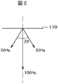
図2は、配光角度の定義を示す図である。図2は、例えば天井に配置された出射面110から床面に向けて光スポットを照射した場合の図である。出射面110の法線方向の光強度が最も大きく、極角が大きくなるにしたがって、光の強度は小さくなる。法線方向の光の強度を100%とし、光強度が50%となるときの極角をθとした場合、配向角は2θである。一般的なコリメート光において要求される配光角度は12度以下である。
FIG. 2 is a diagram showing the definition of the light distribution angle. FIG. 2 is a view when a light spot is irradiated from an exit surface 110 arranged on the ceiling toward the floor surface, for example. The light intensity in the normal direction of the exit surface 110 is the highest, and the light intensity decreases as the polar angle increases. When the light intensity in the normal direction is 100% and the polar angle when the light intensity is 50% is θ, the orientation angle is 2θ. The light distribution angle required for general collimated light is 12 degrees or less.
このようなコリメート光を得るためには、従来はいわゆる放物線ミラー200が使用されていた。図3は、放物線ミラー200を用いた照明装置の平面図であり、図4は、該照明装置の断面図である。図3において、放物線ミラー200の中央にLED20が配置している。LED20は、例えば、LED用PCB基板(Printed Circuit Board)30に配置している。LED20は、高輝度LEDであり、高温になるため、ヒートシンク300の上に配置している。図3において、放物線ミラー200の背面にヒートシンク300の一部が見えている。
Conventionally, a so-called parabolic mirror 200 has been used to obtain such collimated light. FIG. 3 is a plan view of an illuminating device using the parabolic mirror 200, and FIG. 4 is a cross-sectional view of the illuminating device. In FIG. 3, the LED 20 is arranged in the center of the parabolic mirror 200. The LED 20 is arranged on, for example, a PCB board (Printed Circuit Board) 30 for LEDs. The LED 20 is a high-brightness LED and is arranged on the heat sink 300 because it becomes hot. In FIG. 3, a part of the heat sink 300 is visible on the back surface of the parabolic mirror 200.
図4は図3のA-A断面図である。図4において、放物線ミラー200の底面にLED20が配置している。LED20から出射した光は、直上に向かう光の他は、放物線ミラー200において反射し、光軸に平行な光となる。しかし、放物線ミラー200を十分に機能させるためには、放物線ミラー200の高さh1が必要となる。配光角度12度程度を得るためには、放物線ミラーの高さh1は、60mm程度は必要である。実際には、これに、ヒートシンクの高さh2、例えば20mm程度が加わるので、照明装置全体の厚さは80mm以上必要になる。また、図3、4に示す照明装置は、光源を構成する1個のLEDに大きなパワーを供給する必要があるので、LEDの発熱が大きく、ヒートシンクが必須になる。
FIG. 4 is a cross-sectional view taken along the line AA of FIG. In FIG. 4, the LED 20 is arranged on the bottom surface of the parabolic mirror 200. The light emitted from the LED 20 is reflected by the parabolic mirror 200 in addition to the light directly upward, and becomes light parallel to the optical axis. However, in order for the parabolic mirror 200 to function sufficiently, the height h1 of the parabolic mirror 200 is required. In order to obtain a light distribution angle of about 12 degrees, the height h1 of the parabolic mirror needs to be about 60 mm. Actually, since the height h2 of the heat sink, for example, about 20 mm is added to this, the thickness of the entire lighting device needs to be 80 mm or more. Further, in the lighting device shown in FIGS. 3 and 4, since it is necessary to supply a large amount of power to one LED constituting the light source, the heat generated by the LED is large and a heat sink is indispensable.
本発明は、厚さが薄く、比較的小さな消費電力で、コリメート光を発生することが出来る照明装置を実現することであり、また、このような、照明装置を実現するための、プリズムシートの製造を可能とすることである。以下に本発明の内容を詳細に説明する。
The present invention is to realize a lighting device capable of generating collimated light with a thin thickness and relatively small power consumption, and to realize such a lighting device, a prism sheet. It is to enable manufacturing. The contents of the present invention will be described in detail below.
図5は、本発明が適用される照明装置10の一例を示す平面図であり、図6は、図5のB-B断面図である。図5に示すように、照明装置10の平面形状は円であり、最表面には、プリズムシート15が配置している。図5における各光学部品は円板状であり、中央の軸111と円形のフランジ112を有する金属フレーム11の軸111に挿入されている。フレーム11の軸111を囲んでLED20が搭載されたフレキシブル配線基板21が配置し、フレーム11の軸111とフレキシブル21配線基板とは熱伝導シート25で接着している。LED20で発生する熱は、熱伝導シート25を介してフレームの軸111からフランジ112に向けて放散される。照明装置10の外形ddは例えば98mmである。
FIG. 5 is a plan view showing an example of the lighting device 10 to which the present invention is applied, and FIG. 6 is a cross-sectional view taken along the line BB of FIG. As shown in FIG. 5, the planar shape of the lighting device 10 is a circle, and the prism sheet 15 is arranged on the outermost surface. Each optical component in FIG. 5 has a disk shape and is inserted into a shaft 111 of a metal frame 11 having a central shaft 111 and a circular flange 112. A flexible wiring board 21 on which the LED 20 is mounted is arranged around the shaft 111 of the frame 11, and the shaft 111 of the frame 11 and the flexible 21 wiring board are adhered to each other by a heat conductive sheet 25. The heat generated by the LED 20 is dissipated from the shaft 111 of the frame toward the flange 112 via the heat conductive sheet 25. The outer shape dd of the lighting device 10 is, for example, 98 mm.
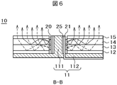
図6は、図5のB-B断面図である。図6において、金属で形成されたフレーム11のフランジ112上に、反射シート12、上導光板13、下導光板14、プリズムシート15がこの順に積層されている。これらの光学部品は中央付近が円形にくりぬかれており、フレーム11の軸111に挿入されている。LED20が搭載されたフレキシブル配線基板21がフレーム11の軸111の周りに、貼り付けられている。フレキシブル配線基板21の一部は、フレーム11のフランジ112の一部に形成された切り欠きを通して、フレーム11の背面に延在している。フレキシブル配線基板21とフレーム11の軸111は、優れた熱伝導を有する熱伝導テープ25を介して接着している。
FIG. 6 is a cross-sectional view taken along the line BB of FIG. In FIG. 6, the reflective sheet 12, the upper light guide plate 13, the lower light guide plate 14, and the prism sheet 15 are laminated in this order on the flange 112 of the frame 11 made of metal. These optical components are hollowed out in a circular shape near the center and are inserted into the shaft 111 of the frame 11. A flexible wiring board 21 on which the LED 20 is mounted is attached around a shaft 111 of the frame 11. A part of the flexible wiring board 21 extends to the back surface of the frame 11 through a notch formed in a part of the flange 112 of the frame 11. The flexible wiring board 21 and the shaft 111 of the frame 11 are adhered to each other via a heat conductive tape 25 having excellent heat conduction.
図6において、矢印は、各LED20から導光板13、14に入射した光の光路の例を示す。点線の矢印は、下側のLEDから下導光板に入射した光の経路であり、実線の矢印は、上側のLEDから上導光板に入射した光の経路である。上導光板14及び下導光板13に入射した光は、導光板の各界面及び反射シート等で反射を繰り返しながら、上側、すなわち、出射面方向に向かう。図6の構成では、上導光板14と下導光板13の界面でも反射をするので、導光板1枚の場合よりもより効率的に光を出射面方向に向けることが出来る。
In FIG. 6, the arrow indicates an example of an optical path of light incident on the light guide plates 13 and 14 from each LED 20. The dotted arrow is the path of light incident on the lower light guide plate from the lower LED, and the solid arrow is the path of light incident on the upper light guide plate from the upper LED. The light incident on the upper light guide plate 14 and the lower light guide plate 13 is directed to the upper side, that is, toward the exit surface while being repeatedly reflected by each interface of the light guide plate and the reflection sheet or the like. In the configuration of FIG. 6, since reflection is also performed at the interface between the upper light guide plate 14 and the lower light guide plate 13, light can be directed toward the emission surface more efficiently than in the case of one light guide plate.
図6において、上導光板14の主面から出射した光は、上導光板14の上に載置されたプリズムシート15によってさらにコリメートされ、照明装置10の出射面の法線方向に向けられる。後で説明するように、円形のプリズムシートには、同心円状にプリズムアレイが形成されている。
In FIG. 6, the light emitted from the main surface of the upper light guide plate 14 is further collimated by the prism sheet 15 placed on the upper light guide plate 14 and directed in the normal direction of the exit surface of the lighting device 10. As will be described later, prism arrays are formed concentrically on the circular prism sheet.
図7は、図6で説明した構成の分解斜視図である。図7において、フレーム11の軸111のまわりに熱伝導シート25を介してLED20を搭載したフレキシブル配線基板21が貼り付けられている。図8は、図7のC-C断面図であり、フレーム11の軸111付近の詳細断面図である。図8において、フレキシブル配線基板21に搭載されたLED20は、2段に形成され、上導光板14と下導光板13の内壁に対向するように配置される。LED20は高温になるが、LED20の熱は、薄いフレキシブル配線基板21と優れた熱伝導を有する熱伝導シート25を介して金属で形成されたフレーム11の軸111に放散される。
FIG. 7 is an exploded perspective view of the configuration described with reference to FIG. In FIG. 7, a flexible wiring board 21 on which the LED 20 is mounted is attached around a shaft 111 of the frame 11 via a heat conductive sheet 25. FIG. 8 is a cross-sectional view taken along the line CC of FIG. 7, which is a detailed cross-sectional view of the frame 11 in the vicinity of the axis 111. In FIG. 8, the LED 20 mounted on the flexible wiring board 21 is formed in two stages and is arranged so as to face the inner walls of the upper light guide plate 14 and the lower light guide plate 13. Although the temperature of the LED 20 becomes high, the heat of the LED 20 is dissipated to the shaft 111 of the frame 11 made of metal via the thin flexible wiring board 21 and the heat conductive sheet 25 having excellent heat conduction.
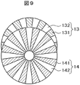
図7に戻り、フレーム11の軸111には、反射シート12、下導光板13、上導光板14、プリズムシート15が挿入される。図9は上導光板14と下導光板13の平面図である。下導光板13及び上導光板14には、プリズムアレイが形成されたパターン領域131、141とプリズムアレイが形成されていない無パターン領域132、142とが存在している。
Returning to FIG. 7, the reflective sheet 12, the lower light guide plate 13, the upper light guide plate 14, and the prism sheet 15 are inserted into the shaft 111 of the frame 11. FIG. 9 is a plan view of the upper light guide plate 14 and the lower light guide plate 13. The lower light guide plate 13 and the upper light guide plate 14 have pattern regions 131 and 141 in which a prism array is formed and non-pattern regions 132 and 142 in which a prism array is not formed.
下導光板13と上導光板14を重ねると、下導光板13のパターン領域131が上導光板14の無パターン領域142に、あるいは、下導光板13の無パターン領域132が上導光板14のパターン領域141に重複することになる。
When the lower light guide plate 13 and the upper light guide plate 14 are overlapped, the pattern region 131 of the lower light guide plate 13 becomes the non-patterned region 142 of the upper light guide plate 14, or the non-pattern region 132 of the lower light guide plate 13 becomes the upper light guide plate 14. It will overlap the pattern area 141.
図10Aは下導光板13のプリズムアレイの構成を示す平面図である。図10Aにおいて、プリズムアレイが形成された領域131と形成されていない領域132が交互に配置している。導光板13の上側(以後主面側ともいう)に形成されたプリズムアレイは半径方向に放射状に形成され、導光板13の下側(以後裏面側ともいう)に形成されたプリズムアレイは同心円状である。そして、LED20は、プリズムアレイが形成された領域の内側面に対向して配置される。
FIG. 10A is a plan view showing the configuration of the prism array of the lower light guide plate 13. In FIG. 10A, the region 131 in which the prism array is formed and the region 132 in which the prism array is not formed are alternately arranged. The prism array formed on the upper side (hereinafter also referred to as the main surface side) of the light guide plate 13 is formed radially in the radial direction, and the prism array formed on the lower side (hereinafter also referred to as the back surface side) of the light guide plate 13 is concentric. Is. Then, the LED 20 is arranged so as to face the inner side surface of the region where the prism array is formed.
図10Bは、図10AのD-D断面図であり、導光板13の主面側に形成されたプリズムアレイを示す断面図である。主面側のプリズムアレイは、中心から半径方向に放射状に延在するパターンである。したがって、プリズムのピッチptは場所によって変化する。導光板13の厚さは、例えば、1.5mmである。プリズムアレイの高さは、例えば0.1μmであり、頂角θtは例えば90度である。
FIG. 10B is a cross-sectional view taken along the line DD of FIG. 10A, showing a prism array formed on the main surface side of the light guide plate 13. The prism array on the main surface side is a pattern extending radially from the center. Therefore, the pitch pt of the prism changes depending on the location. The thickness of the light guide plate 13 is, for example, 1.5 mm. The height of the prism array is, for example, 0.1 μm, and the apex angle θt is, for example, 90 degrees.
図10Cは、図10AのE-E断面図であり、導光板13の裏面側に形成されたプリズムアレイを示す断面図である。裏面側のプリズムアレイは、同心円状に形成されているパターンである。同心円のピッチpbは例えば0.1μmであり、プリズムの高さhbは例えば0.02μmであり、頂角θbは例えば90度である。裏面に形成されたプリズムの高さhbは、主面に形成されたプリズムの高さhtよりも小さい。
FIG. 10C is a cross-sectional view taken along the line EE of FIG. 10A, showing a prism array formed on the back surface side of the light guide plate 13. The prism array on the back surface side is a pattern formed concentrically. The pitch pb of the concentric circles is, for example, 0.1 μm, the height hb of the prism is, for example, 0.02 μm, and the apex angle θb is, for example, 90 degrees. The height hb of the prism formed on the back surface is smaller than the height ht of the prism formed on the main surface.
しかし、導光板13のいずれの面に形成されたプリズムアレイのピッチも、後で説明するプリズムシート15におけるプリズムアレイの高さ及びピッチよりも格段に小さい。したがって、導光板13の主面及び裏面には非常に密度の高いプリズムアレイが形成されることになる。なお、以上の説明では導光板13に形成されるプリズムアレイが突起状のプリズムアレイであるとして説明したが、表面にV溝を形成することによるプリズムアレイによっても同様な効果を得ることが出来る。
However, the pitch of the prism array formed on any surface of the light guide plate 13 is much smaller than the height and pitch of the prism array in the prism sheet 15 described later. Therefore, a very dense prism array is formed on the main surface and the back surface of the light guide plate 13. In the above description, the prism array formed on the light guide plate 13 has been described as a protruding prism array, but the same effect can be obtained by forming a V-groove on the surface of the prism array.
以上は、下導光板13について説明したが、上導光板14も全く同じ形状のものを用いることが出来る。上導光板13と下導光板14は、組み立てるときに方位角方向にずらし、上導光板14のパターン領域と下導光板13の無パターン領域を対応させて配置すればよい。LEDは、下導光板と上導光板の内側面のパターン領域に対応して配置される。
Although the lower light guide plate 13 has been described above, the upper light guide plate 14 can also have exactly the same shape. The upper light guide plate 13 and the lower light guide plate 14 may be displaced in the azimuth direction when assembled, and the pattern region of the upper light guide plate 14 and the non-pattern region of the lower light guide plate 13 may be arranged so as to correspond to each other. The LEDs are arranged corresponding to the pattern regions on the inner side surfaces of the lower light guide plate and the upper light guide plate.
図11Aは、上導光板14の上に配置されるプリズムシート15の平面図である。プリズムシート15は、プリズムアレイ50が上導光板14側の面に形成された、いわゆる逆プリズムシートである。図11Aにおいて、プリズムアレイ50は、同心円状に形成されているので、上導光板14からの光を全周にわたってプリズムシート15の主面の法線方向に集める。
FIG. 11A is a plan view of the prism sheet 15 arranged on the upper light guide plate 14. The prism sheet 15 is a so-called antiprism sheet in which the prism array 50 is formed on the surface of the upper light guide plate 14 side. In FIG. 11A, since the prism array 50 is formed concentrically, the light from the upper light guide plate 14 is collected in the normal direction of the main surface of the prism sheet 15 over the entire circumference.
図11Bは、図11AのF-F断面図であり、プリズムアレイの形状を示す断面図である。図11Bは、プリズムアレイが下側の面に形成されていることを示している。図11Bにおいて、プリズムシート15の厚さtpは、例えば200μm、V溝の深さvdは例えば75μm、頂角θpは例えば66度、ピッチppは、例えば100μmである。このように、プリズムシート15に形成されたプリズムアレイの高さ、ピッチ等は、下導光板13あるいは上導光板14の主面及び裏面に形成されたプリズムアレイの高さやピッチに比べてはるかに大きい。
FIG. 11B is a cross-sectional view taken along the line FF of FIG. 11A, which is a cross-sectional view showing the shape of the prism array. FIG. 11B shows that the prism array is formed on the lower surface. In FIG. 11B, the thickness tp of the prism sheet 15 is, for example, 200 μm, the depth vd of the V groove is, for example, 75 μm, the apex angle θp is, for example, 66 degrees, and the pitch pp is, for example, 100 μm. As described above, the height, pitch, etc. of the prism array formed on the prism sheet 15 are much larger than the height and pitch of the prism arrays formed on the main surface and the back surface of the lower light guide plate 13 or the upper light guide plate 14. big.
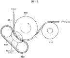
図12は、プリズムシートの製造装置の断面図である。プリズムシートの材料となる、アクリル等による透明樹脂で形成された原反(シート)40が投入側から送られ、この原反40にプリズムアレイのパターンを転写ローラ400から転写する。転写領域で転写ローラ400から原反40に転写をするために、圧迫ローラ420と圧迫ベルト430によって、原反40を転写ローラ400側に強く押し付ける。また、この原反40は、パターンを転写する際は加熱されている。プリズムアレイが転写された後、原反40は、引き出しローラ410を経て、巻取りローラに巻き取られる。その後、プリズムシートは、外形が円形になるように裁断される。
FIG. 12 is a cross-sectional view of a prism sheet manufacturing apparatus. A raw fabric (sheet) 40 made of a transparent resin such as acrylic, which is a material for the prism sheet, is sent from the charging side, and the pattern of the prism array is transferred from the transfer roller 400 to the raw fabric 40. In order to transfer from the transfer roller 400 to the original fabric 40 in the transfer region, the original fabric 40 is strongly pressed against the transfer roller 400 by the compression roller 420 and the compression belt 430. Further, the original fabric 40 is heated when the pattern is transferred. After the prism array is transferred, the original fabric 40 is taken up by the take-up roller via the drawing roller 410. After that, the prism sheet is cut so that the outer shape is circular.
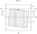
図13は、従来の外形が4角で、線状のプリズムアレイ60を有するプリズムシートを図12のような装置によって製造する場合の、原反40及びプリズムアレイ60が形成された状態を示す平面図である。原反40は白矢印の方向に進むとともに、プリズムアレイ60が転写ローラから転写される。なお、この場合のプリズムアレイ60の断面も図11Bに示すようなV溝が形成された状態になっている。
FIG. 13 is a plane showing a state in which the original fabric 40 and the prism array 60 are formed when a prism sheet having a conventional prism array 60 having a square outer shape is manufactured by an apparatus as shown in FIG. It is a figure. The original fabric 40 advances in the direction of the white arrow, and the prism array 60 is transferred from the transfer roller. The cross section of the prism array 60 in this case is also in a state where a V groove is formed as shown in FIG. 11B.
プリズムアレイ60の延在方向は、原反40の進行方向と同じであるが、プリズムシートの外形は、プリズムアレイの方向とはφだけ傾いている。これは、プリズムシートを製品に組み込んだ時のモアレを対策するためである。
The extending direction of the prism array 60 is the same as the traveling direction of the original fabric 40, but the outer shape of the prism sheet is tilted by φ from the direction of the prism array. This is to prevent moire when the prism sheet is incorporated into the product.
プリズムアレイ60を転写ローラ400から原反40に転写する際、プリズムアレイ60のプリズムの溝と、転写ローラ40との間に空気が巻き込まれる。しかし、この空気は、図14の矢印で示すように、プリズムアレイ60の端部において外側に押し出されるので問題にはならない。
When the prism array 60 is transferred from the transfer roller 400 to the original fabric 40, air is caught between the prism groove of the prism array 60 and the transfer roller 40. However, this air is not a problem because it is pushed outward at the end of the prism array 60, as shown by the arrows in FIG.
図15は、本発明に関連する円形のプリズムシートに形成される同心円状のプリズムアレイ50が転写されている状態を示す原反40の平面図である。図15において、A1-A1線よりも上側が、プリズムアレイ50が転写される前の原反40であり、A1-A1線よりも下側が転写ローラ400によって、原反40にプリズムアレイ50が転写された状態を示す平面図である。原反40は、下側、すなわち、白矢印の方向に進む。
FIG. 15 is a plan view of the original fabric 40 showing a state in which the concentric prism array 50 formed on the circular prism sheet according to the present invention is transferred. In FIG. 15, the upper side of the A1-A1 line is the original fabric 40 before the prism array 50 is transferred, and the lower side of the A1-A1 line is the original fabric 40 transferred to the original fabric 40 by the transfer roller 400. It is a top view which shows the state which was done. The original fabric 40 proceeds downward, that is, in the direction of the white arrow.
図16は、同心円状のプリズムアレイ50を形成する場合の問題点を示す平面図である。図16において、同心円状に形成されたプリズムアレイ50の山と山の間、すなわち、図11BにおけるV溝と、転写ローラ400との間で閉空間が形成され、この中に空気が巻き込まれる。転写を行うとともに、空気は、この閉空間を矢印のようにプリズムアレイの溝に沿って円周方向に移動する。しかし、閉空間であるから、空気の逃げ場がないので、転写ローラと原反との間に気泡が発生し、正確な転写が出来なくなる。
FIG. 16 is a plan view showing problems in forming a concentric prism array 50. In FIG. 16, a closed space is formed between the peaks of the prism array 50 formed concentrically, that is, between the V-groove in FIG. 11B and the transfer roller 400, and air is entrained in the closed space. Along with the transfer, the air moves in this closed space in the circumferential direction along the groove of the prism array as shown by the arrow. However, since it is a closed space, there is no escape place for air, so bubbles are generated between the transfer roller and the original fabric, and accurate transfer cannot be performed.
以下に示す実施例は、このような問題点を対策し、正確なプリズムアレイを有するプリズムシートを実現し、高性能な照明装置を実現するものである。
In the examples shown below, such problems are dealt with, a prism sheet having an accurate prism array is realized, and a high-performance lighting device is realized.
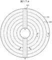
図17Aは、実施例1のプリズムシート15を示す平面図である。図17Aにおいて、同心円状にプリズムアレイ50が形成されている。プリズムアレイ50のF-F断面図は、図11Bと同じである。図17Aの特徴は、半径方向に空気の通り道である、空気抜き溝51が形成されていることである。プリズムアレイ50と転写ローラ400との間に巻き込まれた空気は、プリズムアレイの溝に沿って円周方向に移動し、空気抜き溝51を通って外側に排出される。図17Aでは、この様子を矢印で示している。矢印の向きは、上側でも下側でもよい。空気抜き溝51は、最内周のプリズム、及び最外周のプリズムにも形成されている。
FIG. 17A is a plan view showing the prism sheet 15 of the first embodiment. In FIG. 17A, the prism array 50 is formed concentrically. The FF cross-sectional view of the prism array 50 is the same as in FIG. 11B. The feature of FIG. 17A is that an air vent groove 51, which is an air passage in the radial direction, is formed. The air entrained between the prism array 50 and the transfer roller 400 moves in the circumferential direction along the groove of the prism array and is discharged to the outside through the air vent groove 51. In FIG. 17A, this state is indicated by an arrow. The direction of the arrow may be the upper side or the lower side. The air vent groove 51 is also formed in the innermost prism and the outermost prism.
図17Bは、図17AのG-G断面図であり、空気抜き溝51の断面図である。図17Bの点線で示す深さvdは、図11Bに示すプリズムアレイのV溝の深さvdを示す。図17Bにおいて、空気抜き溝の深さvddは、プリズムアレイ50のV溝の深さvdよりも大きい。空気をより容易に逃がすためである。また、空気を容易に逃がすために、空気抜き溝の幅pd1はプリズムアレイ50のピッチppと同等かそれよりも大きいほうがよい。
FIG. 17B is a cross-sectional view taken along the line GG of FIG. 17A, which is a cross-sectional view of the air vent groove 51. The depth vd shown by the dotted line in FIG. 17B indicates the depth vd of the V-groove of the prism array shown in FIG. 11B. In FIG. 17B, the depth vdd of the air vent groove is larger than the depth vd of the V groove of the prism array 50. This is to allow the air to escape more easily. Further, in order to allow air to escape easily, the width pd1 of the air vent groove should be equal to or larger than the pitch pp of the prism array 50.
図17Cは、同じ図17AのG-G断面図であり、空気抜き溝51の断面図の他の例である。図17Cは、V溝の深さはプリズムアレイ50のV溝の深さvdと同じである。この場合も目的は達することが出来る。図17B及び図17Cにおける空気抜き溝51はV溝であるが、これに限らず、U溝でも、四角の溝でも、半円の溝でもよい。空気抜き溝51は、プリズムアレイ50を構成するわけではないので、製造をしやすい、任意の形状をとることが出来る。
FIG. 17C is a cross-sectional view taken along the line GG of FIG. 17A, which is another example of a cross-sectional view of the air vent groove 51. In FIG. 17C, the depth of the V-groove is the same as the depth vd of the V-groove of the prism array 50. In this case as well, the purpose can be achieved. The air vent groove 51 in FIGS. 17B and 17C is a V groove, but is not limited to this, and may be a U groove, a square groove, or a semicircular groove. Since the air vent groove 51 does not form the prism array 50, it can have an arbitrary shape that is easy to manufacture.
図18Aは、実施例2のプリズムシート15を示す平面図である。図18Aにおいて、同心円状にプリズムアレイ50が形成されている。プリズムアレイ50のF-F断面図は、図11Bと同じである。図17Aの特徴は、同心円状プリズムアレイ50における各円状のプリズムを連続ではなく、不連続にし、飛び飛びにプリズムが形成されていない領域を配置していることである。図18Aにおいて、点線の矢印は空気の通り道である。図18Aでは矢印の向きは下側であるが、矢印の向きは、上側でも下側でもよい。
FIG. 18A is a plan view showing the prism sheet 15 of the second embodiment. In FIG. 18A, the prism array 50 is formed concentrically. The FF cross-sectional view of the prism array 50 is the same as in FIG. 11B. The feature of FIG. 17A is that each circular prism in the concentric prism array 50 is not continuous but discontinuous, and regions in which prisms are not formed are arranged in a discrete manner. In FIG. 18A, the dotted arrow is the air passage. In FIG. 18A, the direction of the arrow is the lower side, but the direction of the arrow may be the upper side or the lower side.
図18Bは、図18AのH-H断面図であり、この不連続部分を示す断面図である。図18Bの点線で示す深さvdは、図11Bに示すプリズムアレイのV溝の深さvdを示す。図18Bにおける、不連続部52は、単に、この部分にプリズムアレイのV状の山が存在しないことを示している。図18Bの不連続部52は、四角であるが、これに限らず、図18Cに示すようなV形状でも、U形状でも半円形状でもよい。また、空気を容易に逃がすために、不連続部分52の円周方向の長さpd2は、プリズムアレイのピッチppと同等かそれよりも大きいほうがよい。
FIG. 18B is a cross-sectional view taken along the line HH of FIG. 18A, and is a cross-sectional view showing this discontinuous portion. The depth vd shown by the dotted line in FIG. 18B indicates the depth vd of the V-groove of the prism array shown in FIG. 11B. The discontinuity 52 in FIG. 18B simply indicates that there are no V-shaped peaks in the prism array at this portion. The discontinuous portion 52 in FIG. 18B is square, but is not limited to this, and may be V-shaped, U-shaped, or semicircular as shown in FIG. 18C. Further, in order to allow air to escape easily, the length pd2 in the circumferential direction of the discontinuous portion 52 should be equal to or larger than the pitch pp of the prism array.
図19Aは、実施例3のプリズムシート15を示す平面図である。図19Aにおいて、同心円状にプリズムアレイ50が形成されている。プリズムアレイ50のF-F断面図は、図11Bと同じである。図19Aの特徴は、1個のプリズムシートを第1のプリズムシートと第2のプリズムシートの2つに分解して製造している点である。2個のプリズムシートの間には、隙間が存在し、これが空気抜き溝となる。図19Aでは、空気の排出方向を示す矢印の向きは下側であるが、矢印の向きは、上側でも下側でもよい。また、空気を容易に逃がすために、2個のプリズムシートの間隔pd3はプリズムアレイ50のピッチppと同等かそれよりも大きいほうがよい。
FIG. 19A is a plan view showing the prism sheet 15 of the third embodiment. In FIG. 19A, the prism array 50 is formed concentrically. The FF cross-sectional view of the prism array 50 is the same as in FIG. 11B. The feature of FIG. 19A is that one prism sheet is disassembled into two parts, a first prism sheet and a second prism sheet, and manufactured. There is a gap between the two prism sheets, which serves as an air vent groove. In FIG. 19A, the direction of the arrow indicating the air discharge direction is the lower side, but the direction of the arrow may be the upper side or the lower side. Further, in order to allow air to escape easily, the distance pd3 between the two prism sheets should be equal to or larger than the pitch pp of the prism array 50.
図19Bは図19AのI-I断面図であり、プリズムシート15は第1のプリズムシートと第2のプリズムシートに分割されていることを示している。図19Bの点線で示す深さvdは、図11Bに示すプリズムアレイのV溝の深さvdを示す。図19A及び図19Bに示すプリズムシート15は、半分ずつ導光板の主面に貼り付けられる。
FIG. 19B is a cross-sectional view taken along the line II of FIG. 19A, showing that the prism sheet 15 is divided into a first prism sheet and a second prism sheet. The depth vd shown by the dotted line in FIG. 19B indicates the depth vd of the V-groove of the prism array shown in FIG. 11B. The prism sheets 15 shown in FIGS. 19A and 19B are attached to the main surface of the light guide plate in half.
以上で説明した外形が円形のプリズムシート15は、中央付近が円状にくり抜かれた形状をしている。しかし、中央付近がくり抜かれず、中央付近まで、同心円状のプリズムアレイが形成されている場合も同様である。図20は、このような場合を示す平面図である。図20において、空気抜き溝51は直径方向に形成されている。
The prism sheet 15 having a circular outer shape described above has a shape in which the vicinity of the center is hollowed out in a circular shape. However, the same applies when the vicinity of the center is not hollowed out and a concentric prism array is formed up to the vicinity of the center. FIG. 20 is a plan view showing such a case. In FIG. 20, the air vent groove 51 is formed in the radial direction.
プリズムシート15を形成するさい、巻き込まれた空気は、矢印で示すように、この空気抜き溝51を通って排出される。図20は実施例1を適用した例であるが、実施例2及び実施例3も同様に適用することが出来る。
When forming the prism sheet 15, the entrained air is discharged through the air vent groove 51 as shown by an arrow. Although FIG. 20 shows an example in which Example 1 is applied, Examples 2 and 3 can be applied in the same manner.
このようにして形成したプリズムシート15を照明装置に用いることによって配向角が小さな、例えば12度程度である、照明装置を実現することが出来る。なお、以上で説明したプリズムシートは、図5、あるいは、図6で示した照明装置のみでなく、種々の照明装置に用いることが出来る。
By using the prism sheet 15 formed in this way for the lighting device, it is possible to realize a lighting device having a small orientation angle, for example, about 12 degrees. The prism sheet described above can be used not only for the lighting device shown in FIG. 5 or FIG. 6 but also for various lighting devices.
以上で説明したプリズムシートは、同心円状のプリズムアレイを有するとして説明したが、本発明は、相似形の複数の楕円によって形成されたプリズムシートの場合にも適用することが出来る。この場合も複数の楕円間のV溝には、閉曲面が形成されることは同じだからである。ただし、相似形の複数の楕円による光の収束効果は、楕円の長軸方向と短軸方向では若干異なることになる。
Although the prism sheet described above has been described as having a concentric prism array, the present invention can also be applied to a prism sheet formed by a plurality of similar ellipses. This is because, in this case as well, a closed curved surface is formed in the V-groove between the plurality of ellipses. However, the effect of light convergence by a plurality of similar ellipses is slightly different in the major axis direction and the minor axis direction of the ellipse.
10…照明装置、 11…基板、 12…反射シート、 13…下導光板、 14…上導光板、 15…プリズムシート、 16…導光板、 17…導光板、 20…LED、
21…LED用フレキシブル配線基板、 25…熱伝導テープ、 30…LED用基板、 40…原反、 50…同心状プリズムアレイ、 51…空気抜き溝、 52…不連続部、 60…線状プリズムアレイ、 110…出射面、 120…被照射面、 130…照射スポット、 200…放物線鏡、 300…ヒートシンク、 400…転写ローラ、
410…引き出し用ローラ、 420…圧迫用ローラ、 430…圧迫用ベルト 10 ... Lighting device, 11 ... Substrate, 12 ... Reflective sheet, 13 ... Lower light guide plate, 14 ... Upper light guide plate, 15 ... Prism sheet, 16 ... Light guide plate, 17 ... Light guide plate, 20 ... LED,
21 ... Flexible wiring board for LED, 25 ... Heat conductive tape, 30 ... Board for LED, 40 ... Original fabric, 50 ... Concentric prism array, 51 ... Air vent groove, 52 ... Discontinuous part, 60 ... Linear prism array, 110 ... exit surface, 120 ... irradiated surface, 130 ... irradiation spot, 200 ... parabolic mirror, 300 ... heat sink, 400 ... transfer roller,
410 ... Drawer roller, 420 ... Compression roller, 430 ... Compression belt
Claims (15)
- 外形が円形であり、一方の面に同心円状のプリズムアレイが形成されたプリズムシートであって、
前記プリズムアレイの中心から半径方向に向けて、前記同心円と交差するように、溝が形成されていることを特徴とするプリズムシート。 A prism sheet having a circular outer shape and a concentric prism array formed on one surface.
A prism sheet characterized in that grooves are formed so as to intersect the concentric circles from the center of the prism array in the radial direction. - 前記溝は、前記プリズムアレイの最内周及び最外周とも交差していることを特徴とする請求項1に記載のプリズムシート。 The prism sheet according to claim 1, wherein the groove also intersects the innermost circumference and the outermost circumference of the prism array.
- 前記溝は、前記プリズムアレイに対して、中心から半径方向に連続して形成されていることを特徴とする請求項1に記載のプリズムシート。 The prism sheet according to claim 1, wherein the groove is continuously formed in the radial direction from the center with respect to the prism array.
- 前記溝の深さは、前記プリズムアレイの深さよりも大きいことを特徴とする請求項1に記載のプリズムシート。 The prism sheet according to claim 1, wherein the depth of the groove is larger than the depth of the prism array.
- 前記プリズムシートの他の面は平面であることを特徴とする請求項1に記載のプリズムシート。 The prism sheet according to claim 1, wherein the other surface of the prism sheet is a flat surface.
- 外形が円形であり、一方の面に同心円状のプリズムアレイが形成されたプリズムシートであって、
前記プリズムアレイを構成する各円形プリズムは、円周方向に不連続な個所が存在していることを特徴とするプリズムシート。 A prism sheet having a circular outer shape and a concentric prism array formed on one surface.
Each circular prism constituting the prism array is a prism sheet characterized in that discontinuous portions exist in the circumferential direction. - 前記不連続な個所は、前記各円形プリズムの一周あたり、複数形成されていることを特徴とする請求項6に記載のプリズムシート。 The prism sheet according to claim 6, wherein a plurality of the discontinuous portions are formed around each circular prism.
- 前記円周方向に不連続な個所は、すべての前記円形プリズムに形成されていることを特徴とする請求項6に記載のプリズムシート。 The prism sheet according to claim 6, wherein the discontinuous portions in the circumferential direction are formed on all the circular prisms.
- 前記プリズムシートの他の面は平面であることを特徴とする請求項6に記載のプリズムシート。 The prism sheet according to claim 6, wherein the other surface of the prism sheet is a flat surface.
- 外形が円形のプリズムシートであって、
前記プリズムシートは、半円形状の第1のプリズムシートと、半円形状の第2のプリズムシートとで構成され、
前記第1のプリズムシートの一方の面には、同心円状に複数の半円からなる第1のプリズムアレイが形成され、
前記第2のプリズムシートの一方の面には、同心円状に複数の半円からなる第2のプリズムアレイが形成され、
前記第1のプリズムシートと前記第2のプリズムシートは、所定の間隔をもって配置されていることを特徴とするプリズムシート。 A prism sheet with a circular outer shape
The prism sheet is composed of a semicircular first prism sheet and a semicircular second prism sheet.
On one surface of the first prism sheet, a first prism array composed of a plurality of semicircles concentrically is formed.
On one surface of the second prism sheet, a second prism array composed of a plurality of semicircles concentrically is formed.
A prism sheet characterized in that the first prism sheet and the second prism sheet are arranged at a predetermined interval. - 前記所定の間隔は、前記第1のプリズムアレイのピッチ及び前記第2のプリズムアレイのピッチと同等かそれよりも大きいことを特徴とする請求項10に記載のプリズムシート。 The prism sheet according to claim 10, wherein the predetermined interval is equal to or larger than the pitch of the first prism array and the pitch of the second prism array.
- 前記第1のプリズムシートの他方の面は平面であり、前記第2のプリズムシートの他方の面は平面であることを特徴とする請求項10に記載のプリズムシート。 The prism sheet according to claim 10, wherein the other surface of the first prism sheet is a flat surface, and the other surface of the second prism sheet is a flat surface.
- 請求項1乃至12のいずれかに記載のプリズムシートを使用した照明装置。 A lighting device using the prism sheet according to any one of claims 1 to 12.
- 請求項5、9、12のいずれかに記載のプリズムシートを使用した照明装置であって、前記プリズムシートの、平面である前記他方の面は、出射面側であることを特徴とする照明装置。 A lighting device using the prism sheet according to any one of claims 5, 9 and 12, wherein the other surface of the prism sheet, which is a flat surface, is on the exit surface side. ..
- 請求項1乃至12のいずれかに記載のプリズムシートは導光板の上に配置されることを特徴とする照明装置。 A lighting device according to any one of claims 1 to 12, wherein the prism sheet is arranged on a light guide plate.
Priority Applications (3)
| Application Number | Priority Date | Filing Date | Title |
|---|---|---|---|
| CN202180020187.XA CN115280062A (en) | 2020-04-15 | 2021-02-02 | Prism sheet and illumination device using the same |
| JP2022515214A JPWO2021210246A1 (en) | 2020-04-15 | 2021-02-02 | |
| US17/963,223 US20230039243A1 (en) | 2020-04-15 | 2022-10-11 | Prism sheet and lighting device using the same |
Applications Claiming Priority (2)
| Application Number | Priority Date | Filing Date | Title |
|---|---|---|---|
| JP2020072757 | 2020-04-15 | ||
| JP2020-072757 | 2020-04-15 |
Related Child Applications (1)
| Application Number | Title | Priority Date | Filing Date |
|---|---|---|---|
| US17/963,223 Continuation US20230039243A1 (en) | 2020-04-15 | 2022-10-11 | Prism sheet and lighting device using the same |
Publications (1)
| Publication Number | Publication Date |
|---|---|
| WO2021210246A1 true WO2021210246A1 (en) | 2021-10-21 |
Family
ID=78084220
Family Applications (1)
| Application Number | Title | Priority Date | Filing Date |
|---|---|---|---|
| PCT/JP2021/003742 WO2021210246A1 (en) | 2020-04-15 | 2021-02-02 | Prism sheet and illumination device using same |
Country Status (4)
| Country | Link |
|---|---|
| US (1) | US20230039243A1 (en) |
| JP (1) | JPWO2021210246A1 (en) |
| CN (1) | CN115280062A (en) |
| WO (1) | WO2021210246A1 (en) |
Citations (5)
| Publication number | Priority date | Publication date | Assignee | Title |
|---|---|---|---|---|
| JPS62153709U (en) * | 1986-03-24 | 1987-09-29 | ||
| JP2004191718A (en) * | 2002-12-12 | 2004-07-08 | Mitsubishi Electric Corp | Led light source device |
| WO2009128885A1 (en) * | 2008-04-14 | 2009-10-22 | Pixtronix, Inc. | Light guides and backlight systems incorporating prismatic structures and light redirectors |
| JP2015072335A (en) * | 2013-10-02 | 2015-04-16 | 株式会社ニコン | Fabrication method of beam-converging device, converging device and light power generation device |
| US20160146427A1 (en) * | 2014-11-21 | 2016-05-26 | Genius Electronic Optical Co., Ltd. | Lens for an illuminating device |
Family Cites Families (3)
| Publication number | Priority date | Publication date | Assignee | Title |
|---|---|---|---|---|
| CN101715565A (en) * | 2007-05-14 | 2010-05-26 | 三菱丽阳株式会社 | Liquid crystal display device, area light source device, prism sheet and their manufacturing method |
| US9411212B2 (en) * | 2013-01-25 | 2016-08-09 | Canon Kabushiki Kaisha | Illumination apparatus which is arrangeable so as to surround an image capturing lens |
| JP6390194B2 (en) * | 2014-06-18 | 2018-09-19 | オムロン株式会社 | Optical element and surface light source device |
-
2021
- 2021-02-02 JP JP2022515214A patent/JPWO2021210246A1/ja active Pending
- 2021-02-02 WO PCT/JP2021/003742 patent/WO2021210246A1/en active Application Filing
- 2021-02-02 CN CN202180020187.XA patent/CN115280062A/en active Pending
-
2022
- 2022-10-11 US US17/963,223 patent/US20230039243A1/en active Pending
Patent Citations (5)
| Publication number | Priority date | Publication date | Assignee | Title |
|---|---|---|---|---|
| JPS62153709U (en) * | 1986-03-24 | 1987-09-29 | ||
| JP2004191718A (en) * | 2002-12-12 | 2004-07-08 | Mitsubishi Electric Corp | Led light source device |
| WO2009128885A1 (en) * | 2008-04-14 | 2009-10-22 | Pixtronix, Inc. | Light guides and backlight systems incorporating prismatic structures and light redirectors |
| JP2015072335A (en) * | 2013-10-02 | 2015-04-16 | 株式会社ニコン | Fabrication method of beam-converging device, converging device and light power generation device |
| US20160146427A1 (en) * | 2014-11-21 | 2016-05-26 | Genius Electronic Optical Co., Ltd. | Lens for an illuminating device |
Also Published As
| Publication number | Publication date |
|---|---|
| CN115280062A (en) | 2022-11-01 |
| JPWO2021210246A1 (en) | 2021-10-21 |
| US20230039243A1 (en) | 2023-02-09 |
Similar Documents
| Publication | Publication Date | Title |
|---|---|---|
| US8681289B2 (en) | Lighting device and liquid crystal display apparatus comprising the same | |
| JP5375966B2 (en) | Surface light source device, liquid crystal display device, and lens | |
| JP6378532B2 (en) | Light emitting device, surface light source device, and display device | |
| WO2011048735A1 (en) | Lighting lens, light-emitting device, surface light source, and liquid crystal display device | |
| JP2006004915A (en) | Illumination device and display device using the same | |
| US10216298B2 (en) | Light module and illuminant mouse pad | |
| US10190736B1 (en) | Apparatus for providing off-axis illumination | |
| JP4739454B2 (en) | LIGHTING DEVICE AND DISPLAY DEVICE USING THE SAME | |
| JP6827301B2 (en) | Optical lens, light source device and lighting device | |
| US20170082261A1 (en) | Illumination device | |
| WO2012169624A1 (en) | Illumination device | |
| TW201506318A (en) | Light emitting diode lamp | |
| JP2007173133A (en) | Light source unit and surface light emitting device | |
| WO2021210246A1 (en) | Prism sheet and illumination device using same | |
| TWI546594B (en) | Backlight module | |
| TW201422989A (en) | Ligh emitting device | |
| JP6127347B2 (en) | lighting equipment | |
| JP2005056711A (en) | Light guide plate unit and flat lighting system | |
| WO2014122707A1 (en) | Lighting device | |
| US20170045668A1 (en) | Light extracting element having serpentine shape, light redirecting element having serpentine shape, and lighting assembly including the same | |
| TW201816488A (en) | Light source and backlight device | |
| US20150345734A1 (en) | Opticial film and light source module | |
| JP2007258059A (en) | Light-emitting device | |
| JP5403453B1 (en) | Fresnel lens sheet and lighting device | |
| US11204151B2 (en) | Optical device and illumination device |
Legal Events
| Date | Code | Title | Description |
|---|---|---|---|
| 121 | Ep: the epo has been informed by wipo that ep was designated in this application |
Ref document number: 21789141 Country of ref document: EP Kind code of ref document: A1 |
|
| ENP | Entry into the national phase |
Ref document number: 2022515214 Country of ref document: JP Kind code of ref document: A |
|
| NENP | Non-entry into the national phase |
Ref country code: DE |
|
| 122 | Ep: pct application non-entry in european phase |
Ref document number: 21789141 Country of ref document: EP Kind code of ref document: A1 |