WO2021206118A1 - Laminate for lithium secondary battery - Google Patents
Laminate for lithium secondary battery Download PDFInfo
- Publication number
- WO2021206118A1 WO2021206118A1 PCT/JP2021/014744 JP2021014744W WO2021206118A1 WO 2021206118 A1 WO2021206118 A1 WO 2021206118A1 JP 2021014744 W JP2021014744 W JP 2021014744W WO 2021206118 A1 WO2021206118 A1 WO 2021206118A1
- Authority
- WO
- WIPO (PCT)
- Prior art keywords
- aluminum
- negative electrode
- secondary battery
- lithium secondary
- aluminum negative
- Prior art date
Links
Images

Classifications
-
- H—ELECTRICITY
- H01—ELECTRIC ELEMENTS
- H01M—PROCESSES OR MEANS, e.g. BATTERIES, FOR THE DIRECT CONVERSION OF CHEMICAL ENERGY INTO ELECTRICAL ENERGY
- H01M4/00—Electrodes
- H01M4/02—Electrodes composed of, or comprising, active material
- H01M4/36—Selection of substances as active materials, active masses, active liquids
- H01M4/38—Selection of substances as active materials, active masses, active liquids of elements or alloys
- H01M4/46—Alloys based on magnesium or aluminium
- H01M4/463—Aluminium based
-
- H—ELECTRICITY
- H01—ELECTRIC ELEMENTS
- H01M—PROCESSES OR MEANS, e.g. BATTERIES, FOR THE DIRECT CONVERSION OF CHEMICAL ENERGY INTO ELECTRICAL ENERGY
- H01M4/00—Electrodes
- H01M4/02—Electrodes composed of, or comprising, active material
- H01M4/13—Electrodes for accumulators with non-aqueous electrolyte, e.g. for lithium-accumulators; Processes of manufacture thereof
- H01M4/134—Electrodes based on metals, Si or alloys
-
- H—ELECTRICITY
- H01—ELECTRIC ELEMENTS
- H01M—PROCESSES OR MEANS, e.g. BATTERIES, FOR THE DIRECT CONVERSION OF CHEMICAL ENERGY INTO ELECTRICAL ENERGY
- H01M10/00—Secondary cells; Manufacture thereof
- H01M10/05—Accumulators with non-aqueous electrolyte
- H01M10/052—Li-accumulators
-
- H—ELECTRICITY
- H01—ELECTRIC ELEMENTS
- H01M—PROCESSES OR MEANS, e.g. BATTERIES, FOR THE DIRECT CONVERSION OF CHEMICAL ENERGY INTO ELECTRICAL ENERGY
- H01M10/00—Secondary cells; Manufacture thereof
- H01M10/05—Accumulators with non-aqueous electrolyte
- H01M10/052—Li-accumulators
- H01M10/0525—Rocking-chair batteries, i.e. batteries with lithium insertion or intercalation in both electrodes; Lithium-ion batteries
-
- H—ELECTRICITY
- H01—ELECTRIC ELEMENTS
- H01M—PROCESSES OR MEANS, e.g. BATTERIES, FOR THE DIRECT CONVERSION OF CHEMICAL ENERGY INTO ELECTRICAL ENERGY
- H01M10/00—Secondary cells; Manufacture thereof
- H01M10/05—Accumulators with non-aqueous electrolyte
- H01M10/056—Accumulators with non-aqueous electrolyte characterised by the materials used as electrolytes, e.g. mixed inorganic/organic electrolytes
- H01M10/0561—Accumulators with non-aqueous electrolyte characterised by the materials used as electrolytes, e.g. mixed inorganic/organic electrolytes the electrolyte being constituted of inorganic materials only
- H01M10/0562—Solid materials
-
- H—ELECTRICITY
- H01—ELECTRIC ELEMENTS
- H01M—PROCESSES OR MEANS, e.g. BATTERIES, FOR THE DIRECT CONVERSION OF CHEMICAL ENERGY INTO ELECTRICAL ENERGY
- H01M10/00—Secondary cells; Manufacture thereof
- H01M10/05—Accumulators with non-aqueous electrolyte
- H01M10/058—Construction or manufacture
- H01M10/0585—Construction or manufacture of accumulators having only flat construction elements, i.e. flat positive electrodes, flat negative electrodes and flat separators
-
- H—ELECTRICITY
- H01—ELECTRIC ELEMENTS
- H01M—PROCESSES OR MEANS, e.g. BATTERIES, FOR THE DIRECT CONVERSION OF CHEMICAL ENERGY INTO ELECTRICAL ENERGY
- H01M4/00—Electrodes
- H01M4/02—Electrodes composed of, or comprising, active material
- H01M4/04—Processes of manufacture in general
- H01M4/043—Processes of manufacture in general involving compressing or compaction
- H01M4/0435—Rolling or calendering
-
- H—ELECTRICITY
- H01—ELECTRIC ELEMENTS
- H01M—PROCESSES OR MEANS, e.g. BATTERIES, FOR THE DIRECT CONVERSION OF CHEMICAL ENERGY INTO ELECTRICAL ENERGY
- H01M4/00—Electrodes
- H01M4/02—Electrodes composed of, or comprising, active material
- H01M4/13—Electrodes for accumulators with non-aqueous electrolyte, e.g. for lithium-accumulators; Processes of manufacture thereof
- H01M4/139—Processes of manufacture
- H01M4/1395—Processes of manufacture of electrodes based on metals, Si or alloys
-
- H—ELECTRICITY
- H01—ELECTRIC ELEMENTS
- H01M—PROCESSES OR MEANS, e.g. BATTERIES, FOR THE DIRECT CONVERSION OF CHEMICAL ENERGY INTO ELECTRICAL ENERGY
- H01M4/00—Electrodes
- H01M4/02—Electrodes composed of, or comprising, active material
- H01M4/36—Selection of substances as active materials, active masses, active liquids
- H01M4/38—Selection of substances as active materials, active masses, active liquids of elements or alloys
- H01M4/381—Alkaline or alkaline earth metals elements
- H01M4/382—Lithium
-
- H—ELECTRICITY
- H01—ELECTRIC ELEMENTS
- H01M—PROCESSES OR MEANS, e.g. BATTERIES, FOR THE DIRECT CONVERSION OF CHEMICAL ENERGY INTO ELECTRICAL ENERGY
- H01M4/00—Electrodes
- H01M4/02—Electrodes composed of, or comprising, active material
- H01M4/64—Carriers or collectors
- H01M4/66—Selection of materials
- H01M4/661—Metal or alloys, e.g. alloy coatings
-
- H—ELECTRICITY
- H01—ELECTRIC ELEMENTS
- H01M—PROCESSES OR MEANS, e.g. BATTERIES, FOR THE DIRECT CONVERSION OF CHEMICAL ENERGY INTO ELECTRICAL ENERGY
- H01M50/00—Constructional details or processes of manufacture of the non-active parts of electrochemical cells other than fuel cells, e.g. hybrid cells
- H01M50/40—Separators; Membranes; Diaphragms; Spacing elements inside cells
- H01M50/409—Separators, membranes or diaphragms characterised by the material
- H01M50/431—Inorganic material
- H01M50/434—Ceramics
-
- H—ELECTRICITY
- H01—ELECTRIC ELEMENTS
- H01M—PROCESSES OR MEANS, e.g. BATTERIES, FOR THE DIRECT CONVERSION OF CHEMICAL ENERGY INTO ELECTRICAL ENERGY
- H01M50/00—Constructional details or processes of manufacture of the non-active parts of electrochemical cells other than fuel cells, e.g. hybrid cells
- H01M50/40—Separators; Membranes; Diaphragms; Spacing elements inside cells
- H01M50/409—Separators, membranes or diaphragms characterised by the material
- H01M50/449—Separators, membranes or diaphragms characterised by the material having a layered structure
-
- H—ELECTRICITY
- H01—ELECTRIC ELEMENTS
- H01M—PROCESSES OR MEANS, e.g. BATTERIES, FOR THE DIRECT CONVERSION OF CHEMICAL ENERGY INTO ELECTRICAL ENERGY
- H01M50/00—Constructional details or processes of manufacture of the non-active parts of electrochemical cells other than fuel cells, e.g. hybrid cells
- H01M50/40—Separators; Membranes; Diaphragms; Spacing elements inside cells
- H01M50/46—Separators, membranes or diaphragms characterised by their combination with electrodes
-
- H—ELECTRICITY
- H01—ELECTRIC ELEMENTS
- H01M—PROCESSES OR MEANS, e.g. BATTERIES, FOR THE DIRECT CONVERSION OF CHEMICAL ENERGY INTO ELECTRICAL ENERGY
- H01M50/00—Constructional details or processes of manufacture of the non-active parts of electrochemical cells other than fuel cells, e.g. hybrid cells
- H01M50/40—Separators; Membranes; Diaphragms; Spacing elements inside cells
- H01M50/489—Separators, membranes, diaphragms or spacing elements inside the cells, characterised by their physical properties, e.g. swelling degree, hydrophilicity or shut down properties
-
- H—ELECTRICITY
- H01—ELECTRIC ELEMENTS
- H01M—PROCESSES OR MEANS, e.g. BATTERIES, FOR THE DIRECT CONVERSION OF CHEMICAL ENERGY INTO ELECTRICAL ENERGY
- H01M4/00—Electrodes
- H01M4/02—Electrodes composed of, or comprising, active material
- H01M2004/021—Physical characteristics, e.g. porosity, surface area
-
- H—ELECTRICITY
- H01—ELECTRIC ELEMENTS
- H01M—PROCESSES OR MEANS, e.g. BATTERIES, FOR THE DIRECT CONVERSION OF CHEMICAL ENERGY INTO ELECTRICAL ENERGY
- H01M4/00—Electrodes
- H01M4/02—Electrodes composed of, or comprising, active material
- H01M2004/026—Electrodes composed of, or comprising, active material characterised by the polarity
- H01M2004/027—Negative electrodes
-
- Y—GENERAL TAGGING OF NEW TECHNOLOGICAL DEVELOPMENTS; GENERAL TAGGING OF CROSS-SECTIONAL TECHNOLOGIES SPANNING OVER SEVERAL SECTIONS OF THE IPC; TECHNICAL SUBJECTS COVERED BY FORMER USPC CROSS-REFERENCE ART COLLECTIONS [XRACs] AND DIGESTS
- Y02—TECHNOLOGIES OR APPLICATIONS FOR MITIGATION OR ADAPTATION AGAINST CLIMATE CHANGE
- Y02E—REDUCTION OF GREENHOUSE GAS [GHG] EMISSIONS, RELATED TO ENERGY GENERATION, TRANSMISSION OR DISTRIBUTION
- Y02E60/00—Enabling technologies; Technologies with a potential or indirect contribution to GHG emissions mitigation
- Y02E60/10—Energy storage using batteries
-
- Y—GENERAL TAGGING OF NEW TECHNOLOGICAL DEVELOPMENTS; GENERAL TAGGING OF CROSS-SECTIONAL TECHNOLOGIES SPANNING OVER SEVERAL SECTIONS OF THE IPC; TECHNICAL SUBJECTS COVERED BY FORMER USPC CROSS-REFERENCE ART COLLECTIONS [XRACs] AND DIGESTS
- Y02—TECHNOLOGIES OR APPLICATIONS FOR MITIGATION OR ADAPTATION AGAINST CLIMATE CHANGE
- Y02P—CLIMATE CHANGE MITIGATION TECHNOLOGIES IN THE PRODUCTION OR PROCESSING OF GOODS
- Y02P70/00—Climate change mitigation technologies in the production process for final industrial or consumer products
- Y02P70/50—Manufacturing or production processes characterised by the final manufactured product
Definitions
- the present invention relates to a laminate for a lithium secondary battery.
- the present application claims priority based on Japanese Patent Application No. 2020-070385 filed in Japan on April 9, 2020, the contents of which are incorporated herein by reference.
- Rechargeable lithium secondary batteries are already being put to practical use not only in small power sources for mobile phones and notebook computers, but also in medium-sized or large-sized power sources for automobiles and power storage.
- Patent Document 1 describes a negative electrode which is a porous aluminum alloy and is composed of a negative electrode active material for a secondary battery containing at least one of silicon or tin. ing.
- a reversible insertion reaction and desorption reaction of lithium ions to the electrodes occur.
- lithium ions are desorbed from the negative electrode and lithium ions are inserted at the positive electrode.
- lithium ions are desorbed from the positive electrode and lithium ions are inserted into the negative electrode.
- a lithium secondary battery is known to have a laminated structure in which positive electrodes, separators, and negative electrodes are alternately laminated.
- the separator is provided to prevent a short circuit between the positive electrode and the negative electrode.
- the present invention has been made in view of the above circumstances, and an object of the present invention is to provide a laminate for a lithium secondary battery capable of smoothly moving lithium ions and improving the battery characteristics of the lithium secondary battery. do.
- the present invention includes the following [1] to [7].
- [1] A laminate for a lithium secondary battery having a plate-shaped aluminum negative electrode capable of occluding and releasing lithium ions and a ceramic separator or a solid electrolyte layer laminated on one of the main surfaces of the aluminum negative electrode.
- [2] The laminate for a lithium secondary battery according to [1], wherein the aluminum negative electrode and the ceramic separator or the solid electrolyte layer are integrated.
- [3] The method according to [1] or [2], wherein the aluminum negative electrode, the ceramic separator or the solid electrolyte layer, and a plate-shaped positive electrode capable of occluding and releasing lithium ions are laminated in this order.
- Laminate for lithium secondary battery
- the aluminum negative electrode is a rolled material, and a rolled surface of the aluminum negative electrode obtained by measuring the surface of the aluminum negative electrode by a backscattering electron diffraction method and a surface perpendicular to the ⁇ 111 ⁇ surface are formed. In the cumulative frequency distribution curve of the absolute values of the angles formed, the angle at which the cumulative frequency from the low angle side is 50% or more is 20 ° or less, assuming that the whole is 100%, of [1] to [6].
- the aluminum negative electrode is a rolled material, and the rolling direction of the aluminum negative electrode obtained by measuring the surface of the aluminum negative electrode by a backscattering electron diffraction method and the normal of the ⁇ 111 ⁇ plane are formed.
- the cumulative frequency distribution curve of the absolute value of the angle when the whole is 100%, the angle at which the cumulative frequency from the low angle side is 50% or more is 20 ° or less, any of [1] to [7].
- the laminate for a lithium secondary battery according to one.
- the present invention includes the following [9] to [12].
- [9] It has a plate-shaped aluminum negative electrode capable of occluding and releasing lithium ions and a ceramic separator or a solid electrolyte layer laminated on one of the main surfaces of the aluminum negative electrode, and the aluminum negative electrode is a rolled material.
- the cumulative frequency distribution curve of the absolute value of the angle formed by the rolled surface of the aluminum negative electrode and the surface perpendicular to the ⁇ 111 ⁇ surface which is obtained by measuring the surface of the aluminum negative electrode by the backscattered electron diffraction method.
- a laminate for a lithium secondary battery in which the angle at which the cumulative frequency from the low angle side is 50% or more is 20 ° or less when 100% is taken.
- It has a plate-shaped aluminum negative electrode capable of occluding and releasing lithium ions and a ceramic separator or a solid electrolyte layer laminated on one of the main surfaces of the aluminum negative electrode, and the aluminum negative electrode is a rolled material.
- the cumulative frequency distribution curve of the absolute value of the angle formed by the rolling direction of the aluminum negative electrode and the normal line of the ⁇ 111 ⁇ plane which is obtained by measuring the surface of the aluminum negative electrode by the backscattered electron diffraction method.
- a laminate for a lithium secondary battery in which the angle at which the cumulative frequency from the low angle side is 50% or more is 20 ° or less when 100% is set.
- An aluminum negative electrode capable of occluding and releasing lithium ions, wherein the aluminum negative electrode is a rolled material composed of an aluminum-containing metal, and the surface of the aluminum negative electrode is measured by a backscattering electron diffraction method.
- the cumulative frequency distribution curve of the absolute value of the angle formed by the rolled surface of the aluminum negative electrode and the surface perpendicular to the ⁇ 111 ⁇ surface the cumulative frequency from the low angle side is 50 when the whole is 100%.
- An aluminum negative electrode having an angle of% or more of 20 ° or less.
- An aluminum negative electrode capable of occluding and releasing lithium ions, wherein the aluminum negative electrode is a rolled material composed of an aluminum-containing metal, and the surface of the aluminum negative electrode is measured by a backscattering electron diffraction method.
- the cumulative frequency distribution curve of the absolute value of the angle formed by the rolling direction of the aluminum negative electrode and the normal line of the ⁇ 111 ⁇ plane the cumulative frequency from the low angle side is 50% when the whole is 100%.
- An aluminum negative electrode having an angle of 20 ° or less.
- the present invention includes the following [13] to [15].
- the aluminum negative electrode is a rolled material, and a rolled surface of the aluminum negative electrode obtained by measuring the surface of the aluminum negative electrode by a backscattering electron diffraction method and a normal of a ⁇ 111 ⁇ surface are formed.
- the cumulative frequency distribution curve of the absolute value of the angle when the whole is 100%, the angle at which the cumulative frequency from the low angle side is 50% or more is 20 ° or less, any of [1] to [6].
- the laminate for a lithium secondary battery according to one.
- It has a plate-shaped aluminum negative electrode capable of occluding and releasing lithium ions and a ceramic separator or a solid electrolyte layer laminated on one of the main surfaces of the aluminum negative electrode, and the aluminum negative electrode is a rolled material.
- the whole is taken as a whole.
- An aluminum negative electrode capable of occluding and releasing lithium ions wherein the aluminum negative electrode is a rolled material composed of an aluminum-containing metal, and the surface of the aluminum negative electrode is measured by a backscattering electron diffraction method.
- the cumulative frequency distribution curve of the absolute value of the angle formed by the rolled surface of the aluminum negative electrode and the normal line of the ⁇ 111 ⁇ surface the cumulative frequency from the low angle side is 50% when the whole is 100%.
- the present invention it is possible to provide a laminate for a lithium secondary battery in which lithium ions can move smoothly and the battery characteristics of the lithium secondary battery can be improved.
- FIG. 1 shows the laminated body 40 of this embodiment.
- the laminate 40 includes an aluminum negative electrode 42 and a ceramic separator 41.
- the aluminum negative electrode 42 has a plate shape and is composed of an aluminum-containing metal capable of storing and releasing lithium ions.
- plate-like means a three-dimensional shape having at least two opposing main surfaces.
- the distance between the two opposing main surfaces described above corresponds to the thickness of the aluminum negative electrode 42.
- Various values can be adopted for the thickness of the aluminum negative electrode 42.
- the plate-shaped aluminum negative electrode 42 includes a thin film-shaped electrode having flexibility that is easy to bend or bend, and a thin plate-shaped electrode that is difficult to bend or bend.
- the aluminum negative electrode 42 includes a ceramic separator 41 on one of the two main surfaces, 42a.
- the ceramic separator 41 has both a role of electrically insulating the positive electrode and the negative electrode and a role of holding the electrolytic solution.
- the aluminum negative electrode 42 and the ceramic separator 41 are integrated in the laminated body 40.
- integrated means that the aluminum negative electrode 42 and the ceramic separator 41 move together when deformed.
- Such a laminated body 40 is unlikely to be displaced or peeled between the aluminum negative electrode 42 and the ceramic separator 41 even when strain is generated by an external force. Therefore, for example, even if the laminated body 40 is distorted, there is no deviation between the aluminum negative electrode 42 and the ceramic separator 41, and a short circuit can be prevented.
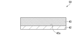
- FIG. 2 shows the laminated body 50 of this embodiment.
- the laminate 50 includes an aluminum negative electrode 42 and a solid electrolyte layer 43.
- the aluminum negative electrode 42 and the solid electrolyte layer 43 are integrated.
- the aluminum negative electrode 42 includes a solid electrolyte layer 43 on one of the two main surfaces, 42a.
- the solid electrolyte layer 43 may serve as a separator, and in that case, the separator may not be required when manufacturing the lithium secondary battery.
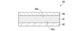
- FIG. 3 shows the laminated body 60 of this embodiment.
- the aluminum negative electrode 42, the ceramic separator 41, and the positive electrode 44 are laminated in this order.
- the positive electrode 44 is made of a material capable of occluding and releasing lithium ions.
- the positive electrode 44 has a plate shape.
- the laminate 60 includes a ceramic separator 41 on the surface 44a of the positive electrode 44 facing the aluminum negative electrode 42.
- the aluminum negative electrode 42 and the ceramic separator 41 are integrated. Further, the positive electrode 44 and the ceramic separator 41 may be integrated.
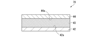
- FIG. 4 shows the laminated body 70 of this embodiment.
- the aluminum negative electrode 42, the solid electrolyte layer 43, and the positive electrode 44 are laminated in this order.
- the aluminum negative electrode 42 and the solid electrolyte layer 43 are preferably integrated.
- the laminate 70 includes a solid electrolyte layer 43 on the surface 44a of the positive electrode 44 facing the aluminum negative electrode 42.
- the aluminum negative electrode is preferably composed of an aluminum-containing metal.
- the aluminum negative electrode is preferably the aluminum negative electrodes 1 to 4 described below.
- the aluminum negative electrode 1 is made of an aluminum-containing metal.
- the aluminum-containing metal acts as a negative electrode active material.
- the aluminum-containing metal of the aluminum negative electrode 1 is present in which the non-aluminum metal phase is dispersed in the aluminum metal phase.
- the non-aluminum metal phase means a metal phase containing no aluminum.
- the non-aluminum metal phase is preferably composed of a non-aluminum metal compound containing at least one selected from the group consisting of Si, Ge, Sn, Ag, Sb, Bi, In and Mg.
- the non-aluminum metal phase is more preferably composed of a non-aluminum metal compound containing at least one selected from the group consisting of Si, Ge, Sn, Ag, Sb, Bi and In.
- the non-aluminum metal phase is preferably composed of non-aluminum metal compound particles.
- the non-aluminum metal compound constituting the non-aluminum metal phase has a very large occlusion of lithium. Therefore, the non-aluminum metal compound has a large volume expansion during lithium insertion and a large volume contraction during lithium desorption. The strain generated by the expansion and contraction develops into cracks of the non-aluminum metal particles, and miniaturization occurs in which the non-aluminum metal compound particles become smaller. The miniaturization of the non-aluminum metal compound acting as the negative electrode active material during charging and discharging causes a shortening of the cycle life.
- the aluminum negative electrode 1 is a metal in which a non-aluminum metal phase is dispersed in an aluminum metal phase.
- the non-aluminum metal compound particles are coated with aluminum which can alloy with lithium.
- the non-aluminum metal compound particles are difficult to crack and therefore difficult to be finely divided. Therefore, it is easy to maintain the initial discharge capacity even when the lithium secondary battery is repeatedly charged and discharged. That is, the discharge capacity retention rate of the lithium secondary battery can be made good.
- the content of the non-aluminum metal phase in the aluminum negative electrode 1 preferably satisfies 0.01% by mass or more and 8% by mass or less with respect to the total amount of the aluminum metal phase and the non-aluminum metal phase.
- the lower limit of the content of the non-aluminum metal phase is preferably 0.02% by mass, more preferably 0.05% by mass, and particularly preferably 0.1% by mass.
- the upper limit of the content of the non-aluminum metal phase is preferably 7% by mass, more preferably 6% by mass, and particularly preferably 5% by mass.
- the above upper limit value and lower limit value can be combined arbitrarily.
- the content of the non-aluminum metal phase is 0.02% by mass or more and 7% by mass or less, 0.05% by mass or more and 6% by mass or less, and 0.1 crystal% or more and 5% by mass or less. Be done.
- the content of the non-aluminum metal phase is equal to or higher than the above lower limit, a metal or metal compound other than aluminum that can contribute to the occlusion of lithium can be sufficiently secured. Further, when the content of the non-aluminum metal phase is not more than the above upper limit value, the dispersed state of the non-aluminum metal phase in the aluminum metal phase tends to be good. Further, when the content of the non-aluminum metal phase is not more than the above upper limit value, rolling tends to be easy.
- the non-aluminum metal phase may contain an arbitrary metal other than Si, Ge, Sn, Ag, Sb, Bi, In and Mg.
- the optional metal include Mn, Zn, Ni and the like.
- the aluminum negative electrode 1 is preferably an Al—Si binary alloy or an Al—Si—Mn ternary alloy. In the case of a ternary alloy, it is preferable that each metal is uniformly solid-solved.
- Sr when the non-aluminum metal phase is Si, Sr may be further contained in order to promote the miniaturization of the non-metal aluminum phase.
- a method for adding Sr to promote the miniaturization of Si the method described in Light Metal Vol. 37, No. 2, 1987, pp. 146-152 can be used.
- the ratio of the area corresponding to the non-aluminum metal phase of the aluminum negative electrode 1 is the area corresponding to the aluminum metal phase and the area corresponding to the non-aluminum metal phase. It is preferable to satisfy 10% or less of the total.
- the aluminum negative electrode 1 is rolled into a foil having a thickness of 0.5 mm.
- the foil is cut perpendicular to the rolling direction and the cut surface is etched with 1.0 mass% sodium hydroxide aqueous solution.
- the aluminum metal phase and the non-aluminum metal phase have different solubilities in sodium hydroxide. Therefore, by etching, a height difference of unevenness is formed between the portion corresponding to the non-aluminum metal phase exposed on the cut surface and the aluminum metal phase due to the difference in solubility.
- the portion corresponding to the aluminum metal phase is a convex portion
- the portion corresponding to the non-aluminum metal phase is a concave portion.
- a cross-sectional image of the cut surface is acquired, and the cross-sectional image is image-processed to binarize the convex portion corresponding to the aluminum metal phase and the concave portion corresponding to the non-aluminum metal phase into black or white, respectively. Get an image.
- the area of the recess corresponds to the area of the non-aluminum metal phase.
- the convex area corresponds to the area of the aluminum metal phase.
- the cross-sectional image can be obtained using, for example, a metallurgical microscope.
- a metallurgical microscope image having a magnification of 200 times or more and 500 times or less is acquired.
- a scanning electron microscope (SEM) is used for the observation.
- SEM scanning electron microscope
- an SEM image having a magnification of 100 times or more and 10,000 times or less is acquired.
- metallurgical microscope for example, Nikon EPIPHOT 300 can be used.
- the obtained SEM image or metallurgical microscope image with the above magnification is taken into a computer and binarized using image analysis software.
- the binarization process is a process of binarizing an intermediate value between the maximum brightness and the minimum brightness in an image.
- a binarized image can be obtained in which the portion corresponding to the aluminum metal phase is white and the portion corresponding to the non-aluminum metal phase is black.
- image analysis software software capable of the above binarization processing can be appropriately selected. Specifically, Image J, Photoshop, Image Pro Plus, or the like can be used as the image analysis software.
- the area corresponding to the aluminum metal phase is S1 and the area corresponding to the non-aluminum metal phase is S2.
- the ratio of S2 to the total of S1 and S2 (S2 / [S1 + S2]) ⁇ 100 (%) preferably satisfies 10% or less, more preferably 6% or less, and particularly preferably 3% or less. preferable.
- the ratio of S2 is not more than the above upper limit value, the non-aluminum metal compound is sufficiently coated with aluminum, so that the non-aluminum metal compound becomes more difficult to crack. Therefore, even when the lithium secondary battery is repeatedly charged and discharged, the initial discharge capacity can be easily maintained.
- the aluminum negative electrode 1 has a non-aluminum metal phase dispersed in an aluminum metal phase.
- the non-aluminum metal phase is dispersed in the aluminum metal phase means a state in which the non-aluminum metal compound phase is present in the aluminum metal matrix.
- the shape surrounded by the outer periphery of the recess corresponding to the non-aluminum metal compound phase observed when observing the cross section of the foil-shaped aluminum negative electrode 1 having a thickness of 0.5 mm is defined as one circle. It is preferable that the number of circles formed satisfies both the following condition (1) and condition (2).
- Condition (1) The number density of the non-aluminum metal compound phase having a circle diameter of 0.1 ⁇ m or more and less than 100 ⁇ m is 1000 pieces / mm 2 or less.
- Condition (2) The number density of the non-aluminum metal compound phase having a circle diameter of 100 ⁇ m or more is 25 pieces / mm 2 or less.
- the diameter of the concave circle corresponding to the non-aluminum metal compound can be obtained by the following method.
- a projected image of a circle of recesses corresponding to a non-aluminum metal compound is obtained from an SEM image photograph or a metallurgical microscope image.
- the distance between the parallel lines (constant direction diameter) when sandwiched between the parallel lines drawn in a certain direction is defined as the diameter of the circle of the recess corresponding to the non-aluminum metal compound.
- the "number density” means the density of the number of circles corresponding to the non-aluminum metal compound existing per unit area in SEM photographs and metal micrographs.
- the aluminum negative electrode 1 is preferably manufactured by a manufacturing method including an alloy casting step and a rolling step.
- -Alloy casting step When casting, first, a predetermined amount of a metal constituting a non-aluminum metal phase is added to aluminum or high-purity aluminum to obtain a mixture 1. High-purity aluminum can be obtained by the method described later. Next, the mixture 1 is melted at 680 ° C. or higher and 800 ° C. or lower to obtain an alloy molten metal 1 of aluminum and metal.
- aluminum constituting the aluminum phase aluminum having a purity of 99.9% by mass or more, high-purity aluminum having a purity of 99.99% by mass or more can be used.
- the metal constituting the non-aluminum metal phase is one or more selected from the group consisting of Si, Ge, Sn, Ag, Sb, Bi, In and Mg.
- the metal constituting the non-aluminum metal phase for example, high-purity silicon having a purity of 99.999% by mass or more is used.
- the molten alloy 1 is subjected to a treatment for cleaning by removing gas and non-metal inclusions.
- cleaning treatment examples include the addition of flux, the treatment of blowing an inert gas or chlorine gas, and the vacuum treatment of molten aluminum.
- the vacuum treatment is performed under the conditions of, for example, 700 ° C. or higher and 800 ° C. or lower, 1 hour or longer and 10 hours or lower, and a vacuum degree of 0.1 Pa or higher and 100 Pa or lower.
- the molten alloy 1 cleaned by vacuum treatment or the like becomes an ingot by casting using a mold.
- a mold an iron mold or a graphite mold heated to 50 ° C. or higher and 200 ° C. or lower is used.
- the aluminum negative electrode 1 can be cast by pouring the molten alloy 1 of 680 ° C. or higher and 800 ° C. or lower into a mold. Further, an ingot may be obtained by semi-continuous casting.
- the obtained ingot of the alloy can be directly cut and used for the aluminum negative electrode 1.
- the ingot is rolled, extruded, forged, or the like to form a plate.
- it is more preferable to make it into a plate shape by rolling.
- the ingot rolling step is, for example, a step of performing hot rolling and cold rolling to process the ingot into a plate shape. Hot rolling is repeated, for example, under the conditions that the temperature of the ingot is 350 ° C. or higher and 550 ° C. or lower and the processing rate per rolling is 2% or higher and 30% or lower, until the aluminum ingot has the desired thickness. ..
- processing rate means the rate of change in thickness when rolling. For example, when a plate having a thickness of 1 mm has a thickness of 0.7 mm, the processing rate is 30%.
- intermediate annealing treatment is performed, for example, by heating a hot-rolled plate material to raise the temperature and then allowing it to cool.
- the temperature raising step in the intermediate annealing treatment may be, for example, raising the temperature to 350 ° C. or higher and 550 ° C. or lower. Further, in the temperature raising step, for example, the temperature of 350 ° C. or higher and 550 ° C. or lower may be maintained for about 1 hour or longer and 5 hours or shorter.
- the cooling step in the intermediate annealing treatment may be performed immediately after the temperature is raised. In the cooling step, it is preferable to allow the mixture to cool to about 20 ° C.
- the cooling step may be appropriately adjusted according to the size of the desired non-aluminum metal phase.
- the cooling step is carried out by allowing to cool rapidly, the non-aluminum metal phase tends to become smaller.
- the cooling step is carried out at a moderate cooling rate, the crystal structure of the metal constituting the non-aluminum metal phase tends to grow.
- Cold rolling is preferably carried out at a temperature lower than the recrystallization temperature of aluminum. Further, it is preferable to repeatedly roll the aluminum ingot to the desired thickness under the condition that the rolling ratio per rolling is 1% or more and 20% or less.
- the temperature of cold rolling may be adjusted from 10 ° C. to 80 ° C. or lower by adjusting the temperature of the metal to be rolled.
- the heat treatment after cold rolling may be carried out in an atmospheric atmosphere, a nitrogen atmosphere, a vacuum atmosphere, or the like.
- a plate material that has been work-hardened by heat treatment can be softened.
- the physical properties such as strength and conductivity can be adjusted within a desired range.
- the heat treatment conditions include conditions for heat treatment at a temperature of 300 ° C. or higher and 400 ° C. or lower for 3 hours or longer and 10 hours or shorter.
- the aluminum negative electrode 1 has a plate shape.
- the thickness of the aluminum negative electrode 1 is preferably 5 ⁇ m or more, more preferably 6 ⁇ m or more, and even more preferably 7 ⁇ m or more. Further, 200 ⁇ m or less is preferable, 190 ⁇ m or less is more preferable, and 180 ⁇ m or less is further preferable.
- the upper limit value and the lower limit value of the thickness of the aluminum negative electrode 1 can be arbitrarily combined.
- the thickness of the aluminum negative electrode 1 preferably satisfies 5 ⁇ m or more and 200 ⁇ m or less.
- the thickness of the aluminum negative electrode 1 may be measured using a thickness gauge or a caliper.
- examples of the purification method for purifying aluminum include the segregation method and the three-layer electrolysis method.
- the segregation method is a purification method that utilizes the segregation phenomenon during solidification of molten aluminum, and a plurality of methods have been put into practical use.
- One form of the segregation method is a method in which molten aluminum is poured into a container, and the molten aluminum at the top is heated and stirred while rotating the container to solidify the purified aluminum from the bottom.
- High-purity aluminum having a purity of 99.99% by mass or more can be obtained by the segregation method.
- the three-layer electrolysis method is an electrolysis method for purifying aluminum.
- relatively low-purity aluminum or the like for example, at the time of JIS-H2102 with a purity of 99.9% by mass or less, about one grade
- it is a method in which an anode is used in a molten state, and an electrolytic bath containing, for example, aluminum fluoride and barium fluoride is placed on the anode to precipitate high-purity aluminum on the cathode.
- an electrolytic bath containing, for example, aluminum fluoride and barium fluoride is placed on the anode to precipitate high-purity aluminum on the cathode.
- the method for purifying aluminum is not limited to the segregation method and the three-layer electrolysis method, but other already known methods such as a band melt purification method and an ultra-high vacuum solubility manufacturing method may be used.
- the aluminum negative electrode 2 is an aluminum-containing metal.
- the aluminum negative electrode 2 has an average corrosion rate of 0.2 mm / year or less as measured by a dipping test under the following dipping conditions.
- the aluminum-containing metal is a test metal piece having a size of 40 mm in length, 40 mm in width, and 0.5 mm in thickness.
- the test metal piece is immersed in a 3.5% NaCl aqueous solution adjusted to pH 3 using acetic acid as a pH adjuster, and the test metal piece is taken out after 72 hours.
- the immersion temperature is 30 ° C.
- Corrosion rate (mm / year) [Corrosion degree x 365] / Specimen density (g / cm 3 )
- test metal piece may be washed with ethanol or the like before being immersed in a 3.5% NaCl aqueous solution adjusted to pH 3.
- the aluminum negative electrode 2 is preferably made of an aluminum-containing metal represented by the following composition formula (1).
- M 1 is one or more selected from the group consisting of Mg, Ni, Mn, Zn, Cd, and Pb.
- M 2 is an unavoidable impurity. 0 mass% ⁇ y ⁇ 8 mass. %, [X / (x + z)] ⁇ 99.9 mass%.)
- M 1 is more preferably one or more elements selected from the group consisting of Mg, Ni, Mn, and Zn.
- y preferably satisfies 0.1% by mass ⁇ y ⁇ 8.0% by mass, preferably 0.5% by mass ⁇ y ⁇ 7.0% by mass, and 0.7% by mass ⁇ . Especially preferably y ⁇ 6.0% by mass.
- the range of y is equal to or greater than the above lower limit value, the average corrosion rate can be controlled within the above range. Further, when the range of y is not more than the above upper limit value, rolling can be performed without cracking during the rolling process at the time of casting.
- M 2 is an unavoidable impurity such as a production residue that is inevitably mixed in the refining step of high-purity aluminum, and specifically, is a metal component other than aluminum and M 1.
- unavoidable impurities include iron and copper.
- z is 0.1% by mass or less, preferably 0.05% by mass or less, and more preferably 0.01% by mass or less.
- [x / (x + z)] is preferably 99.95% or more, more preferably 99.99% or more, and particularly preferably 99.995% or more.
- the aluminum negative electrode 2 contains high-purity aluminum in which [x / (x + z)] is at least the above lower limit value. The refining method for purifying aluminum will be described later.
- those having y exceeding 0 may be described as a high-purity aluminum alloy.
- the high-purity aluminum or the high-purity aluminum alloy according to any one of the following (1) to (5) is preferable.
- High-purity aluminum-magnesium alloy 1 An alloy of 99.999% pure aluminum and magnesium.
- the content of magnesium in the total amount of aluminum-containing metal is 0.1% by mass or more and 4.0% by mass or less.
- the average corrosion rate is 0.04 mm / year to 0.06 mm / year.
- High-purity aluminum-magnesium alloy 2 An alloy of 99.9% pure aluminum and magnesium.
- the content of magnesium in the total amount of aluminum-containing metal is 0.1% by mass or more and 1.0% by mass or less.
- the average corrosion rate is 0.1 mm / year to 0.14 mm / year.
- High-purity aluminum-nickel alloy An alloy of 99.999% pure aluminum and nickel.
- the content of nickel in the total amount of aluminum-containing metal is 0.1% by mass or more and 1.0% by mass or less.
- the average corrosion rate is 0.1 mm / year to 0.14 mm / year.
- High-purity aluminum-manganese-magnesium alloy An alloy of 99.99% pure aluminum, manganese, and magnesium.
- the total content of manganese and magnesium in the total amount of aluminum-containing metal is 1.0% by mass or more and 2.0% by mass or less.
- the average corrosion rate is 0.03 mm / year to 0.05 mm / year.
- the average corrosion rate is 0.05 mm / year.
- the manufacturing method 1 is a manufacturing method when the aluminum negative electrode 2 is high-purity aluminum.
- the manufacturing method 2 is a manufacturing method when the aluminum negative electrode 2 is a high-purity aluminum alloy.
- aluminum is highly purified.
- the method for purifying aluminum include the method for purifying aluminum described in the above-mentioned (method for manufacturing the aluminum negative electrode 1).
- Impurities such as manufacturing residues may be mixed even when the aluminum is highly purified by the high purification method.
- the total content of iron and copper contained in aluminum is preferably 100 ppm or less, more preferably 80 ppm or less, still more preferably 50 ppm or less.
- the manufacturing method 1 preferably includes a casting step of high-purity aluminum and a rolling step.
- Highly purified aluminum can be cast by the above method to obtain an aluminum ingot having a shape suitable for rolling.
- high-purity aluminum is melted at about 680 ° C. or higher and 800 ° C. or lower to obtain a molten aluminum.
- the molten aluminum is preferably subjected to a treatment for cleaning by removing gas and non-metal inclusions. Examples of the cleaning process include the same method as the cleaning process described for the aluminum negative electrode 1.
- the purified molten aluminum is cast into ingots by casting using a mold.
- a mold an iron mold or a graphite mold heated to 50 ° C. or higher and 200 ° C. or lower is used.
- the aluminum negative electrode 2 can be cast by pouring a molten aluminum of 680 ° C. or higher and 800 ° C. or lower into a mold. Further, an ingot may be obtained by semi-continuous casting.
- the obtained ingot of aluminum can be cut as it is and used for the aluminum negative electrode 2. It is preferable that the ingot of aluminum is rolled, extruded, forged, or the like to form a plate material. Further, it is more preferable to roll.
- the rolling step can be carried out by the same method as the rolling step described in the method for manufacturing the aluminum negative electrode 1.
- the manufacturing method 2 preferably includes a casting step of a high-purity aluminum alloy and a rolling step.
- -Casting step When casting, first, a predetermined amount of a metal element is added to high-purity aluminum to obtain a mixture 2. Next, the mixture 2 is melted at 680 ° C. or higher and 800 ° C. or lower to obtain a molten aluminum-metal alloy 2.
- the metal element to be added is preferably one or more elements selected from the group consisting of Mg, Ni, Mn, Zn, Cd, and Pb.
- the metal containing these elements to be added preferably has a purity of 99% by mass or more.
- a high-purity aluminum alloy ingot is obtained by the same method as the casting process in the manufacturing method of the aluminum negative electrode 1 except that the molten alloy 2 is used.
- the rolling process is performed by the same method as in the above-mentioned manufacturing method 1.
- the thickness of the aluminum negative electrode 2 is preferably 5 ⁇ m or more, more preferably 6 ⁇ m or more, and even more preferably 7 ⁇ m or more. Further, 200 ⁇ m or less is preferable, 190 ⁇ m or less is more preferable, and 180 ⁇ m or less is further preferable. The upper limit value and the lower limit value of the thickness of the aluminum negative electrode 2 can be arbitrarily combined. The thickness of the aluminum negative electrode 2 is preferably 5 ⁇ m or more and 200 ⁇ m or less.
- the aluminum negative electrode 3 is an aluminum-containing metal.
- the Vickers hardness of the aluminum negative electrode 3 is preferably 10 HV or more and 70 HV or less, more preferably 20 HV or more and 70 HV or less, further preferably 30 HV or more and 70 HV or less, and particularly preferably 35 HV or more and 55 HV or less.
- the crystal structure of the metal constituting the aluminum negative electrode may be distorted.
- the Vickers hardness is not more than the above upper limit value, it is presumed that the strain of the crystal structure can be relaxed when the aluminum negative electrode 3 occludes lithium, and the crystal structure can be maintained. Therefore, the lithium secondary battery using the aluminum negative electrode 3 can maintain the discharge capacity even when charging and discharging are repeated.
- the Vickers hardness As an index of the hardness of the aluminum negative electrode 3, the Vickers hardness (HV0.05) is measured using a micro Vickers hardness tester.
- the Vickers hardness is a value measured according to JIS Z2244: 2009 "Vickers hardness test-test method". To measure the Vickers hardness, a diamond indenter having a regular quadrangular pyramid is pushed into the surface of the test piece in the aluminum negative electrode 3, the test force is released, and then the hardness is calculated from the diagonal length of the dent remaining on the surface.
- the aluminum negative electrode 4 is a rolled material composed of an aluminum-containing metal.
- the whole is set to 100%.
- the angle at which the cumulative frequency from the low angle side is 50% or more is 20 ° or less.
- the EBSD method is a backscattered electron diffraction method (Electron Backscattered Diffraction Pattern).
- the "angle formed by the rolled surface and the normal of the ⁇ 111 ⁇ plane of the metal crystal contained in the base metal” is the projection of the normal of the ⁇ 111 ⁇ plane on the rolled surface and the ⁇ 111 ⁇ plane. It is an angle between the normal line and 90 ° or less. When the rolled surface and the normal of the ⁇ 111 ⁇ surface are parallel, the above-mentioned angle does not occur. In this case, the angle formed is 0 °.
- the angle formed by the rolled surface and the surface perpendicular to the ⁇ 111 ⁇ surface is defined as follows.
- the angle formed by the rolled surface ⁇ and the surface ⁇ perpendicular to the ⁇ 111 ⁇ plane passes through an arbitrary point O on the line of intersection l of the two planes ⁇ and ⁇ , and is a plane perpendicular to the rolled surface ⁇ and the ⁇ 111 ⁇ plane.
- the angle formed by the straight lines l ⁇ and l ⁇ is defined as the angle formed by the rolled surface ⁇ and the surface ⁇ perpendicular to the ⁇ 111 ⁇ surface.
- the "absolute value of the angle” is an absolute value when the angle is expressed in ⁇ 180 ° notation.
- the whole is set to 100%.
- the angle at which the cumulative frequency from the low angle side is 50% or more is preferably 20 ° or less.
- the EBSD method is widely used as a method for analyzing the orientation distribution of the crystal texture.
- the EBSD method is used in which a backscattered electron diffraction method is mounted on a scanning electron microscope.
- the scanning electron microscope for example, JSM-7900F manufactured by JEOL Ltd. can be used.
- the backscattered electron diffraction detector for example, Symmetry manufactured by Oxford Instruments Co., Ltd. can be used.
- a method for removing the coating on the surface for example, a method by chemical etching using an acid or the like or a method by ion etching using argon ions or the like can be used. Further, the surface coating may be removed by mechanical polishing such as buffing.
- the argon ion beam is obliquely irradiated to the surface of the aluminum negative electrode 4, and the center of the argon ion beam and the center of sample rotation are aligned.
- a method of removing the coating on the surface by a planar argon ion milling method in which a wide area is processed by eccentricity is preferable.
- the surface of the aluminum negative electrode 4 is irradiated with an electron beam. Then, the diffraction pattern of the scattered electrons is read by the device. The obtained diffraction pattern is taken into a computer, and the surface of the aluminum negative electrode 4 is scanned while simultaneously performing crystal orientation analysis. As a result, the crystal is indexed at each measurement point, and the crystal orientation can be obtained. The crystal orientation calculated at each measurement point is recorded in the computer.
- the pixel size of the aluminum negative electrode 4 is preferably 3 ⁇ m or less, and more preferably 1 ⁇ m or less. Further, regarding the analysis region, it is preferable to perform the analysis in a region of 10 mm 2 or more in consideration of the variation depending on the location of the crystal texture.
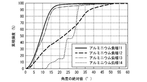
- the cumulative frequency distribution curve of the absolute value of the angle formed by the rolled surface of the aluminum negative electrode 4 and the normal of the ⁇ 111 ⁇ surface of the aluminum-containing metal crystal is obtained.
- the angle at which the cumulative frequency from the low angle side is 50% or more is 20 ° or less, assuming that the total is 100% in the cumulative frequency distribution curve of the obtained absolute values of the angles. It is preferably 15 ° or less, more preferably 12 ° or less.
- the cumulative frequency distribution curve of the absolute value of the angle formed by the rolling direction of the aluminum negative electrode 4 and the normal of the ⁇ 111 ⁇ plane of the aluminum-containing metal crystal is obtained. obtain.
- the angle at which the cumulative frequency from the low angle side is 50% or more is 20 ° or less, assuming that the total is 100% in the cumulative frequency distribution curve of the obtained absolute values of the angles. It is preferably 15 ° or less, more preferably 12 ° or less.
- the ⁇ 111 ⁇ plane of the aluminum-containing metal crystal is oriented so as to be perpendicular to the rolled plane of the aluminum negative electrode 4. It is thought that there is. With such an orientation, the crystal plane orientation is suitable for the elimination and insertion of lithium. In addition, it is presumed that the crystal texture is easily adapted to the volume change that occurs during the desorption and insertion of lithium. Therefore, when the aluminum negative electrode 4 is used, the discharge capacity retention rate of the lithium secondary battery can be improved.
- the aluminum negative electrode 1 may have the properties of the aluminum negative electrode 2. Specifically, it is preferable that the aluminum negative electrode 1 satisfies the average corrosion rate of 0.2 mm / year or less measured by the immersion test under the above immersion conditions.
- the aluminum negative electrode 1 may have the properties of the aluminum negative electrode 3. Specifically, the aluminum negative electrode 1 preferably has a Vickers hardness of 10 HV or more and 70 HV or less.
- the aluminum negative electrode 1 may have the properties of the aluminum negative electrode 4. Specifically, the aluminum negative electrode 1 is a rolled material, and the angle formed by the rolled surface of the aluminum negative electrode and the normal of the ⁇ 111 ⁇ surface, which is obtained by measuring the surface of the aluminum negative electrode by the backscattering electron diffraction method. In the cumulative frequency distribution curve of the absolute value of, it is preferable that the angle at which the cumulative frequency from the low angle side is 50% or more satisfies 20 ° or less, assuming that the whole is 100%.
- the aluminum negative electrode 1 may have the properties of the aluminum negative electrode 4. Specifically, the aluminum negative electrode 1 is a rolled material, and the angle formed by the rolling direction of the aluminum negative electrode and the normal of the ⁇ 111 ⁇ plane, which is obtained by measuring the surface of the aluminum negative electrode by the backscattering electron diffraction method. In the cumulative frequency distribution curve of the absolute value of, it is preferable that the angle at which the cumulative frequency from the low angle side is 50% or more satisfies 20 ° or less, assuming that the whole is 100%.
- the aluminum negative electrode 1 may have the properties of the aluminum negative electrode 2 and the aluminum negative electrode 3. Specifically, it is preferable that the aluminum negative electrode 1 satisfies the average corrosion rate of 0.2 mm / year or less measured by the immersion test under the above immersion conditions and the Vickers hardness of 10 HV or more and 70 HV or less.
- the aluminum negative electrode 2 may have the properties of the aluminum negative electrode 3. Specifically, the aluminum negative electrode 2 preferably has a Vickers hardness of 10 HV or more and 70 HV or less.
- the aluminum negative electrode 1 may have the properties of the aluminum negative electrode 2, the aluminum negative electrode 3, and the aluminum negative electrode 4. Specifically, the aluminum negative electrode 1 satisfies the average corrosion rate of 0.2 mm / year or less measured by the immersion test under the above immersion conditions, the Vickers hardness satisfies 10 HV or more and 70 HV or less, and the aluminum negative electrode 1 is rolled. In the cumulative frequency distribution curve of the absolute value of the angle formed by the rolled surface of the aluminum negative electrode and the normal line of the ⁇ 111 ⁇ surface, which is a material and is obtained by measuring the surface of the aluminum negative electrode by the backscattering electron diffraction method. When the whole is 100%, it is preferable that the angle at which the cumulative frequency from the low angle side is 50% or more satisfies 20 ° or less.
- the aluminum negative electrode 1 may have the properties of the aluminum negative electrode 2, the aluminum negative electrode 3, and the aluminum negative electrode 4. Specifically, the aluminum negative electrode 1 satisfies the average corrosion rate of 0.2 mm / year or less measured by the immersion test under the above immersion conditions, the Vickers hardness satisfies 10 HV or more and 70 HV or less, and the aluminum negative electrode 1 is rolled. In the cumulative frequency distribution curve of the absolute value of the angle formed by the rolling direction of the aluminum negative electrode and the normal line of the ⁇ 111 ⁇ plane, which is obtained by measuring the surface of the aluminum negative electrode by the backward scattering electron diffraction method. When the whole is 100%, it is preferable that the angle at which the cumulative frequency from the low angle side is 50% or more satisfies 20 ° or less.
- the aluminum negative electrode 2 may have the properties of the aluminum negative electrode 3 and the aluminum negative electrode 4. Specifically, the aluminum negative electrode 2 has a Vickers hardness of 10 HV or more and 70 HV or less, and the aluminum negative electrode 1 is a rolled material, which is obtained by measuring the surface of the aluminum negative electrode by a backscattering electron diffraction method. In the cumulative frequency distribution curve of the absolute value of the angle formed by the rolled surface of the negative electrode and the normal of the ⁇ 111 ⁇ surface, when the whole is 100%, the angle at which the cumulative frequency from the low angle side is 50% or more is It is preferable to satisfy 20 ° or less.
- the aluminum negative electrode 2 may have the properties of the aluminum negative electrode 3 and the aluminum negative electrode 4. Specifically, the aluminum negative electrode 2 has a Vickers hardness of 10 HV or more and 70 HV or less, and the aluminum negative electrode 1 is a rolled material, which is obtained by measuring the surface of the aluminum negative electrode by a backscattering electron diffraction method. In the cumulative frequency distribution curve of the absolute value of the angle formed by the rolling direction of the negative electrode and the normal of the ⁇ 111 ⁇ plane, when the whole is 100%, the angle at which the cumulative frequency from the low angle side is 50% or more is It is preferable to satisfy 20 ° or less.
- the component analysis of the aluminum negative electrode can be performed using an emission spectroscopic analyzer. This makes it possible to quantify the amount of metal elements in the aluminum-containing metal.
- the luminescence spectroscopic analyzer for example, a model: ARL-4460, manufactured by Thermo Fisher Scientific Co., Ltd. can be used.
- the metal element can be quantified more accurately by a glow discharge mass spectrometer.
- the material of the negative electrode current collector may be a strip-shaped member made of a metal material such as Cu, Ni, or stainless steel.
- a metal material such as Cu, Ni, or stainless steel.
- Cu is used as a forming material and processed into a thin film because it is difficult to form an alloy with lithium and it is easy to process.
- Examples of the method of supporting the negative electrode mixture on such a negative electrode current collector include a method of pressure molding, a method of pasting with a solvent and the like, coating on the negative electrode current collector, drying, and pressing and crimping.
- the ceramic separator 41 is a microporous ceramic film.
- the ceramic contained in the ceramic separator 41 is preferably at least one selected from MgO, Al 2 O 3 , ZrO 2 , SiC, Si 3 N 4 , AlN, and cordierite, and more preferably MgO, Al. At least one selected from 2 O 3 and ZrO 2.
- the ceramic separator 41 may contain polyethylene beads or polypropylene beads.
- a shutdown function can be imparted to the ceramic separator when the temperature becomes high.
- the shutdown function means a function in which the components constituting the separator are melted in a high temperature state to block the movement path of lithium ions and stop charging / discharging.
- polyethylene beads for example, Flow Beads CL, Flow Beads HE, and Flowsen UF manufactured by Sumitomo Seika Chemical Co., Ltd. can be used.
- polypropylene beads for example, Flow Beads RP manufactured by Sumitomo Seika Chemical Co., Ltd. can be used.
- the median diameter of the polyethylene beads or polypropylene beads preferably satisfies 10 ⁇ m or more and 20 ⁇ m or less.
- the content ratio of polyethylene beads or polypropylene beads in the total amount of the ceramic separator is preferably 1% or more and less than 10%, and more preferably 2% or more and 5% or less.
- the temperature at which the shutdown function is exhibited can be adjusted as appropriate depending on the type of polyethylene beads or polypropylene beads.
- the thickness of the ceramic separator is preferably 3 ⁇ m or more and 40 ⁇ m or less, more preferably 5 ⁇ m or more and 35 ⁇ m or less, and further preferably 10 ⁇ m or more and 30 ⁇ m or less.
- the air permeation resistance by the Garley method defined by JIS P 8117 must be 50 seconds / 100 cc or more and 300 seconds / 100 cc or less. It is preferably 50 seconds / 100 cc or more and 200 seconds / 100 cc or less.
- the porosity of the separator is preferably 30% by volume or more and 80% by volume or less, and more preferably 40% by volume or more and 70% by volume or less.
- the separator may be a stack of separators having different porosities.
- Solid electrolyte As the solid electrolyte that the solid electrolyte layer 43 may have, a solid electrolyte that has lithium ion conductivity and is used in a known all-solid-state battery can be adopted. Examples of such a solid electrolyte include an inorganic electrolyte and an organic electrolyte.
- Examples of the inorganic electrolyte include oxide-based solid electrolytes, sulfide-based solid electrolytes, and hydride-based solid electrolytes.
- Examples of the organic electrolyte include polymer-based solid electrolytes.
- oxide-based solid electrolyte examples include perovskite-type oxides, NASICON-type oxides, LISION-type oxides, garnet-type oxides, and the like.
- Examples of the perovskite-type oxide include Li-La-Ti oxides such as Li a La 1-a TIO 3 (0 ⁇ a ⁇ 1) and Li b La 1-b TaO 3 (0 ⁇ b ⁇ 1). Examples thereof include Li-La-Ta-based oxides and Li-La-Nb-based oxides such as Li c La 1-c NbO 3 (0 ⁇ c ⁇ 1).
- NASICON type oxide examples include Li 1 + d Al d Ti 2-d (PO 4 ) 3 (0 ⁇ d ⁇ 1).
- NASICON type oxide Li m M 1 n M 2 o P p O q (wherein, M 1 is, selected B, Al, Ga, In, C, Si, Ge, Sn, from the group consisting of Sb and Se one or more elements .M 2 to the Ti, Zr, Ge, an in, Ga, one or more elements selected from the group consisting of Sn and Al .m, n, o, p and q are arbitrary positive It is an oxide represented by a number.).
- Li 4 M 3 O 4- Li 3 M 4 O 4 (M 3 is one or more elements selected from the group consisting of Si, Ge, and Ti. M 4 is P, As. And an oxide represented by one or more elements selected from the group consisting of V.).
- garnet-type oxide examples include Li-La-Zr-based oxides such as Li 7 La 3 Zr 2 O 12 (LLZ).
- the oxide-based solid electrolyte may be a crystalline material or an amorphous material.
- amorphous solid electrolytes such as Li-BO compounds such as Li 3 BO 3, Li 2 B 4 O 7, LiBO 2 and the like.
- the oxide-based solid electrolyte preferably contains an amorphous material.
- sulfide-based solid electrolyte examples include Li 2 SP 2 S 5 series compounds, Li 2 S—SiS 2 series compounds, Li 2 S—GeS 2 series compounds, Li 2 SB 2 S 3 series compounds, and Li 2 S-P 2 S 3 type compound, LiI-Si 2 S-P 2 S 5, LiI-Li 2 S-P 2 O 5, LiI-Li 3 PO 4 -P 2 S 5, Li 10 GeP 2 S 12 etc. Can be mentioned.
- system compound which refers to a sulfide-based solid electrolyte is a solid electrolyte mainly containing raw materials such as "Li 2 S" and "P 2 S 5" described before “system compound”. It is used as a general term for.
- the Li 2 SP 2 S 5 system compound contains a solid electrolyte containing Li 2 S and P 2 S 5 and further containing other raw materials.
- the Li 2 SP 2 S 5 series compounds also include solid electrolytes having different mixing ratios of Li 2 S and P 2 S 5.
- Li 2 The S-P 2 S 5 -based compounds, Li 2 S-P 2 S 5, Li 2 S-P 2 S 5 -LiI, Li 2 S-P 2 S 5 -LiCl, Li 2 S-P 2 S 5 -LiBr, Li 2 S- P 2 S 5 -Li 2 O, Li 2 S-P 2 S 5 -Li 2 O-LiI, Li 2 S-P 2 S 5 -Z m S n (m, n Is a positive number.
- Z can be Ge, Zn, Ga) or the like.
- the Li 2 S-SiS 2 based compound Li 2 S-SiS 2, Li 2 S-SiS 2 -LiI, Li 2 S-SiS 2 -LiBr, Li 2 S-SiS 2 -LiCl, Li 2 S-SiS 2- B 2 S 3- LiI, Li 2 S-SiS 2- P 2 S 5- LiI, Li 2 S-SiS 2 -Li 3 PO 4 , Li 2 S-SiS 2 -Li 2 SO 4 , Li 2 S -SiS 2- Li x MO y (x, y are positive numbers.
- M is P, Si, Ge, B, Al, Ga or In) and the like.
- Li 2 S-GeS 2 system compound examples include Li 2 S-GeS 2 and Li 2 S-GeS 2- P 2 S 5 .
- the sulfide-based solid electrolyte may be a crystalline material or an amorphous material.
- the sulfide-based solid electrolyte preferably contains an amorphous material.
- the hydride-based solid electrolyte material LiBH 4, LiBH 4 -3KI, LiBH 4 -PI 2, LiBH 4 -P 2 S 5, LiBH 4 -LiNH 2, 3LiBH 4 -LiI, LiNH 2, Li 2 AlH 6, Li (NH 2 ) 2 I, Li 2 NH, LiGd (BH 4 ) 3 Cl, Li 2 (BH 4 ) (NH 2 ), Li 3 (NH 2 ) I, Li 4 (BH 4 ) (NH 2 ) 3 And so on.
- polymer-based solid electrolyte examples include organic polymer electrolytes such as polyethylene oxide-based polymer compounds, polymer compounds containing one or more selected from the group consisting of polyorganosiloxane chains and polyoxyalkylene chains. .. Further, a so-called gel type compound in which a non-aqueous electrolytic solution is retained in a polymer compound can also be used.
- Two or more types of solid electrolytes can be used in combination as long as the effects of the invention are not impaired.
- the solid electrolyte when a solid electrolyte is used, the solid electrolyte may serve as a separator, and in that case, the separator may not be required. Further, the solid electrolyte layer may be mixed with polyethylene beads or polypropylene beads to impart a shutdown function to the solid electrolyte layer.
- polyethylene beads or polypropylene beads the same material as the polyethylene beads or polypropylene beads that may be used for the ceramic separator can be used.
- the content ratio of polyethylene beads or polypropylene beads in the total amount of the solid electrolyte layer is preferably 1% or more and less than 10%, and more preferably 2% or more and 5% or less.
- the positive electrode has a positive electrode active material.
- a lithium-containing compound or another metal compound can be used as the positive electrode active material.
- the lithium-containing compound include a lithium cobalt composite oxide having a layered structure, a lithium nickel composite oxide having a layered structure, a lithium manganese composite oxide having a spinel structure, and lithium iron phosphate having an olivine type structure. ..
- Examples of other metal compounds include oxides such as titanium oxide, vanadium oxide and manganese dioxide, and sulfides such as titanium sulfide and molybdenum sulfide.
- a carbon material As the conductive material, a carbon material can be used.
- the carbon material include graphite powder, carbon black (for example, acetylene black), and fibrous carbon material. Since carbon black is fine and has a large surface area, it is possible to increase the conductivity inside the positive electrode and improve the charge / discharge efficiency and output characteristics by adding a small amount to the positive electrode mixture.
- the ratio of the conductive material in the positive electrode mixture is preferably 5 parts by mass or more and 20 parts by mass or less with respect to 100 parts by mass of the positive electrode active material.
- a fibrous carbon material such as graphitized carbon fiber or carbon nanotube is used as the conductive material, this ratio can be reduced.
- thermoplastic resin As the binder, a thermoplastic resin can be used.
- this thermoplastic resin include polyvinylidene fluoride, polytetrafluoroethylene, ethylene tetrafluoride / propylene hexafluoride / vinylidene fluoride copolymer, propylene hexafluoride / vinylidene fluoride copolymer, and tetrafluoride.
- Fluororesin such as ethylene / perfluorovinyl ether-based copolymer; polyolefin resin such as polyethylene and polypropylene; can be mentioned.
- thermoplastic resins may be used as a mixture of two or more types. Fluororesin and polyolefin resin are used as binders, and the ratio of fluororesin to the entire positive electrode mixture is 1% by mass or more and 10% by mass or less, and the ratio of polyolefin resin is 0.1% by mass or more and 2% by mass or less. It is possible to obtain a positive electrode mixture having high adhesion to the current collector and high bonding force inside the positive electrode mixture.
- the positive electrode current collector As the positive electrode current collector, a band-shaped member made of a metal material such as Al, Ni, or stainless steel can be used. Of these, Al is used as a forming material and processed into a thin film because it is easy to process and inexpensive.
- Examples of the method of supporting the positive electrode mixture on the positive electrode current collector include a method of pressure molding the positive electrode mixture on the positive electrode current collector. Further, the positive electrode mixture is made into a paste using an organic solvent, and the obtained positive electrode mixture paste is applied to at least one surface side of the positive electrode current collector, dried, pressed and fixed to the positive electrode current collector. The mixture may be carried.
- the organic solvents that can be used include amine solvents such as N, N-dimethylaminopropylamine and diethylenetriamine; ether solvents such as tetrahydrofuran; ketone solvents such as methyl ethyl ketone; methyl acetate. Etc.; amide-based solvents such as dimethylacetamide and N-methyl-2-pyrrolidone;
- Examples of the method of applying the positive electrode mixture paste to the positive electrode current collector include a slit die coating method, a screen coating method, a curtain coating method, a knife coating method, a gravure coating method and an electrostatic spray method.
- the positive electrode can be manufactured by the methods listed above.
- the laminate of the present embodiment can be produced by applying a separator-forming composition to one surface of an aluminum negative electrode, drying the separator-forming composition, and removing the solvent.
- a separator-forming composition for example, a composition of alumina and 1% hydroxypropyl methylcellulose can be used.
- the separator-forming composition preferably has a solid content concentration of 40% or more and 60% or less.
- the method of applying the separator-forming composition to one surface of the aluminum negative electrode is not particularly limited, and for example, a method of applying the composition using an applicator can be used.
- the coating film thickness of the separator forming composition can be appropriately adjusted in the range of, for example, 100 ⁇ m or more and 250 ⁇ m or less.
- the conditions for drying the coating film of the separator forming composition may be appropriately adjusted depending on the coating film thickness and the type of solvent.
- heat drying for example, it may be dried at a temperature of 50 ° C. or higher and 100 ° C. or lower for 30 minutes to 5 hours.
- the laminate of the present embodiment may be manufactured by laminating a preformed separator on an aluminum negative electrode.
- a method of forming a separator in advance first, a composition for forming a separator is applied to a base material. Next, the separator-forming composition is dried to remove the solvent to form a coating film. Further, the formed coating film is peeled off from the substrate to obtain a separator. By laminating the obtained separator on the aluminum negative electrode, the laminated body of the present embodiment can be obtained.
- the base material for example, a base material made of polyethylene terephthalate can be used.
- the lithium secondary battery of the present embodiment includes the laminate of the present embodiment.
- the lithium secondary battery according to the present embodiment will be described with reference to the drawings.
- the lithium secondary battery of the present embodiment may be a liquid-based lithium secondary battery having an electrolytic solution, or may be a solid electrolyte type lithium secondary battery.
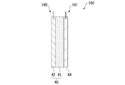
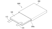
- the lithium secondary battery 1000 shown in FIG. 5 has a positive electrode 44 and a laminate 40.
- the laminate 40 has an aluminum negative electrode 42 and a ceramic separator 41.
- the lithium secondary battery 1000 is housed in the exterior body 200 shown in FIG. It is preferable that the lithium secondary battery 1000 is housed in the exterior body 200a, and then the ceramic separator in the laminate 100 is impregnated with the electrolytic solution to seal the exterior body 200.
- the lithium secondary battery 1000 may have an external terminal 113 connected to the positive electrode 44 and an external terminal 123 connected to the aluminum negative electrode 42.
- the lithium secondary battery 1000 has an insulator (not shown) that insulates the laminate 100 and the exterior body 200.
- a container formed of a metal material having high corrosion resistance such as aluminum, stainless steel, and nickel-plated steel can be used.
- Examples of the shape of the lithium secondary battery 1000 include a coin type, a button type, a paper type (or a sheet type, a cylindrical type, a square type, and an aluminum laminated type).
- the aluminum negative electrode expands on the first charge and then becomes porous by discharging. As a result, voids are formed in the aluminum negative electrode. Then, the electrolytic solution having a volume corresponding to the formed voids becomes insufficient. Therefore, it is preferable to add an excess electrolytic solution to prevent a shortage of the electrolytic solution.
- the material of the lead connected to the aluminum negative electrode and the sheet-shaped positive electrode can be appropriately selected from nickel, copper, iron, stainless steel or aluminum. From a potential point of view, the leads are preferably made of aluminum.
- the electrolytic solution used for the liquid-based lithium secondary battery will be described.
- the electrolytes contained in the electrolytic solution include LiClO 4 , LiPF 6 , LiAsF 6 , LiSbF 6 , LiBF 4 , LiCF 3 SO 3 , LiN (SO 2 CF 3 ) 2 , LiN (SO 2 C 2 F 5 ) 2 , LiN.
- the electrolyte is at least selected from the group consisting of LiPF 6 , LiAsF 6 , LiSbF 6 , LiBF 4 , LiCF 3 SO 3 , LiN (SO 2 CF 3 ) 2 and LiC (SO 2 CF 3 ) 3 containing fluorine. It is preferable to use one containing one type.
- organic solvent contained in the electrolytic solution examples include propylene carbonate, ethylene carbonate, dimethyl carbonate, diethyl carbonate, ethylmethyl carbonate, 4-trifluoromethyl-1,3-dioxolan-2-one, 1,2-di ( Carbonates such as methoxycarbonyloxy) ethane; 1,2-dimethoxyethane, 1,3-dimethoxypropane, pentafluoropropylmethyl ether, 2,2,3,3-tetrafluoropropyldifluoromethyl ether, tetrahydrofuran, 2-methyl Ethers such as tetrahydrofuran; esters such as methyl formate, methyl acetate, propyl ⁇ -butyrolactone propionate; nitriles such as acetonitrile and butyronitrile; amides such as N, N-dimethylformamide, N, N-dimethylacetamide; 3 Carbamates such as -methyl-2-
- the organic solvent it is preferable to use a mixture of two or more of these.
- a mixed solvent containing carbonates is preferable, and a mixed solvent of cyclic carbonate and acyclic carbonate and a mixed solvent of cyclic carbonate and ethers are more preferable.
- a mixed solvent of the cyclic carbonate and the acyclic carbonate a mixed solvent containing ethylene carbonate, dimethyl carbonate and ethyl methyl carbonate is preferable.
- An electrolytic solution using such a mixed solvent has a wide operating temperature range, is not easily deteriorated even when charged and discharged at a high current rate, is not easily deteriorated even when used for a long time, and is made of natural graphite as an active material of a negative electrode. It has many features that it is resistant to decomposition even when a graphite material such as artificial graphite is used.
- an electrolytic solution containing a lithium salt containing fluorine such as LiPF 6 and an organic solvent having a fluorine substituent it is preferable to use an electrolytic solution containing a lithium salt containing fluorine such as LiPF 6 and an organic solvent having a fluorine substituent.
- a mixed solvent containing ethers having a fluorine substituent such as pentafluoropropylmethyl ether and 2,2,3,3-tetrafluoropropyldifluoromethyl ether and dimethyl carbonate has a capacity even when charged and discharged at a high current rate. It is more preferable because of its high maintenance rate.
- the electrolytic solution may contain additives such as tris (trimethylsilyl) phosphate and tris borate (trimethylsilyl).
- the lithium secondary battery may be a solid electrolyte type secondary battery using a solid electrolyte.
- the solid electrolyte type secondary battery has a positive electrode and a laminate of the present embodiment.
- the laminate has an aluminum negative electrode and a solid electrolyte layer.
- the solid electrolyte layer is in contact with the positive electrode.
- the positive electrode preferably has voids on the surface in contact with the solid electrolyte layer. It is preferable that the material constituting the solid electrolyte fills a part of the voids.
- the above-mentioned solid electrolyte can be used.
- the porosity of the positive electrode is preferably 10% or more and 50% or less, more preferably 20% or more and 50% or less, and particularly preferably 30% or more and 50% or less. Further, it is preferable that at least 10% of the voids contained in the positive electrode are filled with the material constituting the solid electrolyte.
- the lithium secondary battery is evaluated by assembling the lithium secondary battery and measuring the discharge capacity retention rate.
- Preparation of positive electrode 90 parts by mass of lithium cobalt oxide as a positive electrode active material, 5 parts by mass of vinylidene polyfluoride as a binder, 5 parts by mass of acetylene black as a conductive material, and 70 parts by mass of N-methyl-2-pyrrolidone were further mixed. Use as a positive electrode mixture.
- the obtained electrode mixture is coated on an aluminum foil having a thickness of 15 ⁇ m, which is a current collector, by a doctor blade method.
- the coated electrode mixture is dried at 60 ° C. for 2 hours and then vacuum dried at 150 ° C. for 10 hours to volatilize N-methyl-2-pyrrolidone.
- the amount of the positive electrode active material applied after drying is 21.5 mg / cm 2 .
- a positive electrode was placed on the ceramic separator of the above laminated body.
- a coin-shaped (or) lithium secondary battery having a diameter of 20 mm and a thickness of 3.2 mm is produced by storing the battery case (standard 2032), injecting the above electrolytic solution, and sealing the battery case.
- the obtained cross section was observed using a metallurgical microscope (Nikon EPIPHOT 300) at a magnification of 200 times.
- image analysis software image-Pro Plus
- the obtained image was binarized and the aluminum metal phase was simply binarized to white and the non-aluminum metal phase to black.
- Corrosion rate (mm / year) [Corrosion degree x 365] / Specimen density (g / cm 3 )
- the Vickers hardness (HV0.05) of the aluminum-containing metal obtained by the method described later was measured using a Micro Vickers hardness tester as an index of hardness.
- the Vickers hardness is a value measured according to JIS Z2244: 2009 "Vickers hardness test-test method".
- a micro Vickers hardness tester manufactured by Shimadzu Corporation was used for the measurement.
- the Vickers hardness was measured from the diagonal length of the dent remaining on the surface after the diamond indenter of a regular quadrangular pyramid was pushed into the surface of the test piece (metal leaf) and the force to push the indenter (test force) was released.
- a backscattered electron diffraction image was obtained using a scanning electron microscope on the surface of the aluminum negative electrode on which a clean surface was obtained.
- the conditions for acquiring the backscattered electron diffraction image were as follows. Equipment (scanning electron microscope): JSM-7900F, JEOL Ltd. Device (Backscatter Electron Diffraction Detector): Oxford Instruments Co., Ltd. Symmetry Acceleration voltage: 15kV Current value: 72.5nA
- the obtained diffraction pattern was taken into a computer, and the surface of the aluminum negative electrode was scanned while simultaneously performing crystal orientation analysis.
- the pixel size at the time of scanning was 1 ⁇ m, and the measurement was carried out over a region of 12 mm 2.
- the crystal is indexed at each measurement point (measurement pixel) to obtain the crystal orientation, and the crystal orientation calculated at each measurement point is recorded in the computer.
- the cumulative frequency of the absolute value of the angle formed by the rolling direction of the aluminum negative electrode and the normal of the (111) plane of the aluminum-containing metal crystal from the crystal orientation information at each measurement point recorded on the computer. A distribution curve was obtained.
- Example 1 [Manufacturing of aluminum negative electrode]
- the silicon-aluminum alloy used in Example 1 was produced by the following method. By heating and holding high-purity aluminum (purity: 99.99% by mass or more) and high-purity chemical silicon (purity: 99.999% by mass or more) at 760 ° C., the silicon content is 1.0% by mass. A molten silicon-aluminum alloy was obtained. Next, the molten alloy was kept at a temperature of 740 ° C. for 2 hours under the condition of a vacuum degree of 50 Pa for cleaning. The molten alloy was cast in a cast iron mold (22 mm ⁇ 150 mm ⁇ 200 mm) dried at 150 ° C. to obtain an ingot.
- a cast iron mold 22 mm ⁇ 150 mm ⁇ 200 mm
- Rolling was carried out under the following conditions. After chamfering both sides of the ingot by 2 mm, cold rolling was performed from a thickness of 18 mm at a processing rate of 99.4%. The thickness of the obtained rolled material was 100 ⁇ m.
- the number density of the non-aluminum metal compound particles having a particle diameter of 0.1 ⁇ m or more and less than 100 ⁇ m is 318. It was / mm 2. Further, in the aluminum negative electrode 11, the number density of non-aluminum metal compound particles having a particle diameter of 100 ⁇ m or more was 9 particles / mm 2 .
- the particle size of the non-aluminum metal compound particles is the distance between the parallel lines when the projected image of the cross-sectional shape of the non-aluminum metal compound particles is sandwiched between parallel lines drawn in a certain direction from the SEM image photograph at a magnification of 10,000 times. (Constant direction diameter) was measured as the particle size of the non-aluminum metal compound particles.
- the "number density” means the density of the number of non-aluminum metal compound particles existing per unit area in an SEM image photograph having a magnification of 10,000 times.
- Alumina manufactured by Sumitomo Chemical Co., Ltd., product name "AKP3000”
- 1% hydroxypropylmethylcellulose are mixed at a ratio of solid content concentration of 50%, and a thin film swirl type high-speed mixer (manufactured by Primix Corporation, Philmix).
- a thin film swirl type high-speed mixer manufactured by Primix Corporation, Philmix.
- the slurry composition was applied to one surface of the aluminum negative electrode 11 using an applicator to form a coating film having a thickness of 230 ⁇ m.
- it was dried at 60 ° C. for 1 hour to produce a laminate for a lithium secondary battery having a ceramic separator on one surface of the aluminum negative electrode 11.
- the obtained laminated body for a lithium secondary battery was cut out into a disk shape having a diameter of 16 mm (ceramic separator of the laminated body).
- lithium cobalt oxide product name CellSeed, manufactured by Nippon Chemical Industrial Co., Ltd., average particle size (D50) 10 ⁇ m
- vinylidene polyfluoride manufactured by Kureha Co., Ltd.
- a conductive material As a result, 5 parts by mass of acetylene black (product name: Denka Black, manufactured by Den
- the obtained electrode mixture was coated on an aluminum foil having a thickness of 15 ⁇ m, which is a current collector, by a doctor blade method.
- the coated electrode mixture was dried at 60 ° C. for 2 hours and then vacuum dried at 150 ° C. for 10 hours to volatilize N-methyl-2-pyrrolidone.
- the amount of the positive electrode active material applied after drying was 21.5 mg / cm 2 .
- a positive electrode was placed on the ceramic separator of the above laminated body.
- a coin-type (full-cell) lithium secondary battery having a diameter of 20 mm and a thickness of 3.2 mm was produced by storing the battery case (standard 2032), injecting the above electrolytic solution, and sealing the battery case.
- An aluminum negative electrode 12 was produced in the same manner as in Example 1 except that a molten aluminum-silicon alloy having a silicon content of 1.0% by mass was obtained, cold rolled, and then heat-treated at 350 ° C. for 3 hours. bottom.
- Al negative electrode 13 An aluminum foil (thickness 100 ⁇ m) having a purity of 99.99% was used as the aluminum negative electrode 13.
- Al negative electrode 14 An aluminum foil (thickness 100 ⁇ m) having a purity of 99.99%, which was subjected to cold rolling and then heat-treated at 350 ° C. for 3 hours, was used as the aluminum negative electrode 14.
- FIG. 8 shows the cumulative frequency distribution of the absolute values of the angles formed by the rolling direction of the aluminum negative electrodes 11 to 14 and the normal of the (111) plane, which are obtained by measuring the aluminum negative electrodes 11 to 14 by the backscattered electron diffraction method. Shows a curve.
- Table 1 shows the angles of the aluminum negative electrodes 11 to 14 at which the cumulative frequency is 50% or more.
- Solid electrolyte 1 was produced as a sulfide-based solid electrolyte. Specifically, weigh 15 g and 5 g of each into a ball mill container so that Li 2 S (manufactured by Furuuchi Chemical Co., Ltd.) is 75 parts by mass and P 2 S 5 (manufactured by Merck) is 25 parts by mass, and weigh zirconia balls. Solid electrolyte 1 was prepared by pulverizing and mixing for 24 hours.
- Solid electrolyte 2 2 g of Sumitomo Seika Chemical's flow beads (LE-1080) was added to 20 g of the solid electrolyte 1 after the ball mill, and the mixture was further mixed for 1 hour to prepare the solid electrolyte 2.
- Preparation of positive electrode 1 62 parts by mass of LiNi 0.6 Mn 0.2 Co 0.2 O 2 coated with niobium as a positive electrode active material, 5 parts by mass of acetylene black as a conductive material, and 30 parts by mass of a solid electrolyte 1 are mixed. bottom.
- a slurry for a positive electrode active material was prepared by mixing 3 parts by mass of butadiene rubber (BR) as a binder and 60 parts by mass of heptane as a dispersion medium with the mixed powder shown on the left.
- BR butadiene rubber
- a thin film swirl type high-speed mixer was used as in "Preparation of a laminate for a lithium secondary battery having a ceramic separator".
- the slurry for positive electrode active material was applied to an aluminum current collector (A1085 having a thickness of 15 ⁇ m) using an applicator, and dried at 60 ° C. (the heptane of the dispersion medium was removed) to obtain a coating film.
- a 70 ⁇ m positive electrode sheet was produced by compacting the coating film with a roll press. The above positive electrode sheet was punched to ⁇ 14 mm to prepare a positive electrode 1.
- the positive electrode 2 was produced in the same manner except that the solid electrolyte of the positive electrode 1 was changed to the solid electrolyte 2.
- a solid electrolyte 1 slurry was prepared by mixing 97 parts by mass of solid electrolyte 1, 3 parts by mass of butadiene rubber (BR) as a binder, and 60 parts by mass of heptane as a dispersion medium.
- BR butadiene rubber
- a slurry is prepared using a thin film swirling high-speed mixer in the same manner as in the production of the positive electrode 1, applied to one surface of the aluminum negative electrode 11 using an applicator, and dried at 60 ° C. (dispersant). Heptane was removed) to obtain a coating film.
- a negative electrode sheet integrated with the solid electrolyte 1 having a thickness of 230 ⁇ m was produced.
- the negative electrode integrated with the solid electrolyte 1 was punched to ⁇ 16 mm to prepare the negative electrode 1.
- the negative electrode 2 was produced in the same manner except that the solid electrolyte of the negative electrode 1 was changed to the solid electrolyte 2.
- the positive electrode 1 and the negative electrode 1 are housed in a battery case (standard 2032), and by sealing the battery case, a coin-type (full cell) solid electrolyte lithium secondary battery 1 having a diameter of 20 mm and a thickness of 3.2 mm is sealed. Was produced.
- a solid electrolyte lithium secondary battery 2 was produced in the same manner as the solid electrolyte lithium secondary battery 1 except that the negative electrode was the negative electrode 2.
- a solid electrolyte lithium secondary battery 3 was produced in the same manner as the solid electrolyte lithium secondary battery 1 except that the positive electrode was the positive electrode 2.
- a solid electrolyte lithium secondary battery 4 was produced in the same manner as the solid electrolyte lithium secondary battery 1 except that the negative electrode was the negative electrode 2 and the positive electrode was the positive electrode 2.
- the solid electrolyte lithium secondary batteries 1 to 4 of the present embodiment were evaluated by assembling the lithium secondary batteries and performing a charge / discharge test.
- the solid electrolyte lithium secondary batteries 1 to 4 of the present embodiment were evaluated by assembling the lithium secondary batteries, heating them, and then performing a charge / discharge test.
- the solid electrolyte lithium secondary batteries 2 to 4 exhibit a shutdown function because the flow beads (FB) of the solid electrolyte reduce the lithium ion conductivity of the solid electrolyte by heating. It is probable that the progress of the reaction stopped and charging could not be performed.
- FB flow beads
- the lithium secondary battery laminate of the present invention can be used to produce a high temperature resistant solid electrolyte lithium secondary battery. From this effect, it can be fully inferred that the battery specifications can be appropriately changed according to the application and environment in which the battery is used.
Landscapes
- Chemical & Material Sciences (AREA)
- Chemical Kinetics & Catalysis (AREA)
- Electrochemistry (AREA)
- General Chemical & Material Sciences (AREA)
- Engineering & Computer Science (AREA)
- Manufacturing & Machinery (AREA)
- Materials Engineering (AREA)
- Inorganic Chemistry (AREA)
- Ceramic Engineering (AREA)
- Physics & Mathematics (AREA)
- Condensed Matter Physics & Semiconductors (AREA)
- General Physics & Mathematics (AREA)
- Battery Electrode And Active Subsutance (AREA)
- Cell Electrode Carriers And Collectors (AREA)
- Secondary Cells (AREA)
Abstract
This laminate for a lithium secondary battery comprises a metal negative electrode capable of storing and releasing lithium ions, a positive electrode capable of storing and releasing lithium ions, and an electrolyte, the negative electrode being formed from an aluminum-containing metal. The metal negative electrode is sheet-shaped and includes a ceramic separator or solid electrolyte layer on a surface, from among the planar surfaces of the metal negative electrode, that faces the positive electrode.
Description
本発明は、リチウム二次電池用積層体に関する。
本願は2020年4月9日に、日本に出願された特願2020-070385号に基づき優先権を主張し、その内容をここに援用する。 The present invention relates to a laminate for a lithium secondary battery.
The present application claims priority based on Japanese Patent Application No. 2020-070385 filed in Japan on April 9, 2020, the contents of which are incorporated herein by reference.
充電が可能なリチウム二次電池は、既に携帯電話用途やノートパソコン用途などの小型電源だけでなく、自動車用途や電力貯蔵用途などの中型又は大型電源においても、実用化が進んでいる。
Rechargeable lithium secondary batteries are already being put to practical use not only in small power sources for mobile phones and notebook computers, but also in medium-sized or large-sized power sources for automobiles and power storage.
リチウム二次電池を構成する負極について、従来の負極材料である黒鉛よりも理論容量が大きい材料を用い、電池性能を向上させる検討が行われている。このような材料として、黒鉛と同様に、例えばリチウムイオンを吸蔵可能及び放出可能な金属材料が注目されている。
For the negative electrode that constitutes a lithium secondary battery, studies are being conducted to improve the battery performance by using a material having a theoretical capacity larger than that of graphite, which is a conventional negative electrode material. As such a material, as with graphite, for example, a metal material capable of occluding and releasing lithium ions has attracted attention.
金属材料から形成された負極の例として、例えば特許文献1には、多孔質のアルミニウム合金であり、シリコン又はスズの少なくとも1種を含む二次電池用負極活物質から構成される負極が記載されている。
As an example of a negative electrode formed of a metal material, for example, Patent Document 1 describes a negative electrode which is a porous aluminum alloy and is composed of a negative electrode active material for a secondary battery containing at least one of silicon or tin. ing.
リチウム二次電池の充電過程及び放電過程において、電極へのリチウムイオンの可逆的な挿入反応と脱離反応とがおこる。例えばリチウム二次電池を充電させたとき、負極からリチウムイオンが脱離し、正極においてリチウムイオンが挿入する。またリチウム二次電池を放電させたとき、正極からリチウムイオンが脱離し、負極にリチウムイオンが挿入される。
In the charging process and discharging process of the lithium secondary battery, a reversible insertion reaction and desorption reaction of lithium ions to the electrodes occur. For example, when a lithium secondary battery is charged, lithium ions are desorbed from the negative electrode and lithium ions are inserted at the positive electrode. When the lithium secondary battery is discharged, lithium ions are desorbed from the positive electrode and lithium ions are inserted into the negative electrode.
リチウム二次電池は、正極、セパレータ、及び負極が交互に積層された積層型の構成が知られている。セパレータは、正極と負極との間での短絡を防止するために設けられる。リチウム二次電池の応用分野が拡大するなかで、リチウムイオンがスムーズに移動でき、電池特性を向上させることが求められる。
A lithium secondary battery is known to have a laminated structure in which positive electrodes, separators, and negative electrodes are alternately laminated. The separator is provided to prevent a short circuit between the positive electrode and the negative electrode. As the application fields of lithium secondary batteries expand, it is required that lithium ions can move smoothly and the battery characteristics are improved.
本発明は上記事情に鑑みてなされたものであって、リチウムイオンがスムーズに移動でき、リチウム二次電池の電池特性を向上させることができるリチウム二次電池用積層体を提供することを目的とする。
The present invention has been made in view of the above circumstances, and an object of the present invention is to provide a laminate for a lithium secondary battery capable of smoothly moving lithium ions and improving the battery characteristics of the lithium secondary battery. do.
本発明は以下の[1]~[7]を包含する。
[1]リチウムイオンを吸蔵及び放出可能な板状のアルミニウム負極と、前記アルミニウム負極の主面の一方に積層された、セラミックセパレータ又は固体電解質層を有する、リチウム二次電池用積層体。
[2]前記アルミニウム負極と前記セラミックセパレータ又は固体電解質層が一体化している、[1]に記載のリチウム二次電池用積層体。
[3]前記アルミニウム負極と、前記セラミックセパレータ又は前記固体電解質層と、リチウムイオンを吸蔵及び放出可能な板状の正極と、がこの順で積層された、[1]又は[2]に記載のリチウム二次電池用積層体。
[4]前記アルミニウム負極は、アルミニウム金属相に非アルミニウム金属相が分散している金属から構成される、[1]~[3]のいずれか1つに記載のリチウム二次電池用積層体。
[5]前記アルミニウム負極は、下記の浸漬条件の浸漬試験により測定される平均腐食速度が0.2mm/年以下である、[1]~[4]のいずれか1つに記載のリチウム二次電池用積層体。
[浸漬条件]
浸漬液:酢酸をpH調整剤として用い、pH3に調整した3.5%NaCl水溶液
浸漬温度:30℃
浸漬時間:72時間
[6]前記アルミニウム負極は、ビッカース硬度が10Hv以上70Hv以下である、[1]~[5]のいずれか1つに記載のリチウム二次電池用積層体。
[7]前記アルミニウム負極は圧延材であって、前記アルミニウム負極の表面を、後方散乱電子回折法により測定して得られる、前記アルミニウム負極の圧延面と、{111}面と垂直な面とが成す角度の絶対値の累積頻度分布曲線において、全体を100%としたとき、低角度側からの累積頻度が50%以上となる角度が、20°以下である、[1]~[6]のいずれか1つに記載のリチウム二次電池用積層体。
[8]前記アルミニウム負極は圧延材であって、前記アルミニウム負極の表面を、後方散乱電子回折法により測定して得られる、前記アルミニウム負極の圧延方向と、{111}面の法線とが成す角度の絶対値の累積頻度分布曲線において、全体を100%としたとき、低角度側からの累積頻度が50%以上となる角度が、20°以下である、[1]~[7]のいずれか1つに記載のリチウム二次電池用積層体。 The present invention includes the following [1] to [7].
[1] A laminate for a lithium secondary battery having a plate-shaped aluminum negative electrode capable of occluding and releasing lithium ions and a ceramic separator or a solid electrolyte layer laminated on one of the main surfaces of the aluminum negative electrode.
[2] The laminate for a lithium secondary battery according to [1], wherein the aluminum negative electrode and the ceramic separator or the solid electrolyte layer are integrated.
[3] The method according to [1] or [2], wherein the aluminum negative electrode, the ceramic separator or the solid electrolyte layer, and a plate-shaped positive electrode capable of occluding and releasing lithium ions are laminated in this order. Laminate for lithium secondary battery.
[4] The laminate for a lithium secondary battery according to any one of [1] to [3], wherein the aluminum negative electrode is composed of a metal in which a non-aluminum metal phase is dispersed in an aluminum metal phase.
[5] The lithium secondary according to any one of [1] to [4], wherein the aluminum negative electrode has an average corrosion rate of 0.2 mm / year or less measured by an immersion test under the following immersion conditions. Laminate for batteries.
[Immersion conditions]
Immersion solution: 3.5% NaCl aqueous solution adjusted topH 3 using acetic acid as a pH adjuster Immersion temperature: 30 ° C.
Immersion time: 72 hours [6] The laminate for a lithium secondary battery according to any one of [1] to [5], wherein the aluminum negative electrode has a Vickers hardness of 10 Hv or more and 70 Hv or less.
[7] The aluminum negative electrode is a rolled material, and a rolled surface of the aluminum negative electrode obtained by measuring the surface of the aluminum negative electrode by a backscattering electron diffraction method and a surface perpendicular to the {111} surface are formed. In the cumulative frequency distribution curve of the absolute values of the angles formed, the angle at which the cumulative frequency from the low angle side is 50% or more is 20 ° or less, assuming that the whole is 100%, of [1] to [6]. The laminate for a lithium secondary battery according to any one.
[8] The aluminum negative electrode is a rolled material, and the rolling direction of the aluminum negative electrode obtained by measuring the surface of the aluminum negative electrode by a backscattering electron diffraction method and the normal of the {111} plane are formed. In the cumulative frequency distribution curve of the absolute value of the angle, when the whole is 100%, the angle at which the cumulative frequency from the low angle side is 50% or more is 20 ° or less, any of [1] to [7]. The laminate for a lithium secondary battery according to one.
[1]リチウムイオンを吸蔵及び放出可能な板状のアルミニウム負極と、前記アルミニウム負極の主面の一方に積層された、セラミックセパレータ又は固体電解質層を有する、リチウム二次電池用積層体。
[2]前記アルミニウム負極と前記セラミックセパレータ又は固体電解質層が一体化している、[1]に記載のリチウム二次電池用積層体。
[3]前記アルミニウム負極と、前記セラミックセパレータ又は前記固体電解質層と、リチウムイオンを吸蔵及び放出可能な板状の正極と、がこの順で積層された、[1]又は[2]に記載のリチウム二次電池用積層体。
[4]前記アルミニウム負極は、アルミニウム金属相に非アルミニウム金属相が分散している金属から構成される、[1]~[3]のいずれか1つに記載のリチウム二次電池用積層体。
[5]前記アルミニウム負極は、下記の浸漬条件の浸漬試験により測定される平均腐食速度が0.2mm/年以下である、[1]~[4]のいずれか1つに記載のリチウム二次電池用積層体。
[浸漬条件]
浸漬液:酢酸をpH調整剤として用い、pH3に調整した3.5%NaCl水溶液
浸漬温度:30℃
浸漬時間:72時間
[6]前記アルミニウム負極は、ビッカース硬度が10Hv以上70Hv以下である、[1]~[5]のいずれか1つに記載のリチウム二次電池用積層体。
[7]前記アルミニウム負極は圧延材であって、前記アルミニウム負極の表面を、後方散乱電子回折法により測定して得られる、前記アルミニウム負極の圧延面と、{111}面と垂直な面とが成す角度の絶対値の累積頻度分布曲線において、全体を100%としたとき、低角度側からの累積頻度が50%以上となる角度が、20°以下である、[1]~[6]のいずれか1つに記載のリチウム二次電池用積層体。
[8]前記アルミニウム負極は圧延材であって、前記アルミニウム負極の表面を、後方散乱電子回折法により測定して得られる、前記アルミニウム負極の圧延方向と、{111}面の法線とが成す角度の絶対値の累積頻度分布曲線において、全体を100%としたとき、低角度側からの累積頻度が50%以上となる角度が、20°以下である、[1]~[7]のいずれか1つに記載のリチウム二次電池用積層体。 The present invention includes the following [1] to [7].
[1] A laminate for a lithium secondary battery having a plate-shaped aluminum negative electrode capable of occluding and releasing lithium ions and a ceramic separator or a solid electrolyte layer laminated on one of the main surfaces of the aluminum negative electrode.
[2] The laminate for a lithium secondary battery according to [1], wherein the aluminum negative electrode and the ceramic separator or the solid electrolyte layer are integrated.
[3] The method according to [1] or [2], wherein the aluminum negative electrode, the ceramic separator or the solid electrolyte layer, and a plate-shaped positive electrode capable of occluding and releasing lithium ions are laminated in this order. Laminate for lithium secondary battery.
[4] The laminate for a lithium secondary battery according to any one of [1] to [3], wherein the aluminum negative electrode is composed of a metal in which a non-aluminum metal phase is dispersed in an aluminum metal phase.
[5] The lithium secondary according to any one of [1] to [4], wherein the aluminum negative electrode has an average corrosion rate of 0.2 mm / year or less measured by an immersion test under the following immersion conditions. Laminate for batteries.
[Immersion conditions]
Immersion solution: 3.5% NaCl aqueous solution adjusted to
Immersion time: 72 hours [6] The laminate for a lithium secondary battery according to any one of [1] to [5], wherein the aluminum negative electrode has a Vickers hardness of 10 Hv or more and 70 Hv or less.
[7] The aluminum negative electrode is a rolled material, and a rolled surface of the aluminum negative electrode obtained by measuring the surface of the aluminum negative electrode by a backscattering electron diffraction method and a surface perpendicular to the {111} surface are formed. In the cumulative frequency distribution curve of the absolute values of the angles formed, the angle at which the cumulative frequency from the low angle side is 50% or more is 20 ° or less, assuming that the whole is 100%, of [1] to [6]. The laminate for a lithium secondary battery according to any one.
[8] The aluminum negative electrode is a rolled material, and the rolling direction of the aluminum negative electrode obtained by measuring the surface of the aluminum negative electrode by a backscattering electron diffraction method and the normal of the {111} plane are formed. In the cumulative frequency distribution curve of the absolute value of the angle, when the whole is 100%, the angle at which the cumulative frequency from the low angle side is 50% or more is 20 ° or less, any of [1] to [7]. The laminate for a lithium secondary battery according to one.
本発明は以下の[9]~[12]を包含する。
[9]リチウムイオンを吸蔵及び放出可能な板状のアルミニウム負極と、前記アルミニウム負極の主面の一方に積層された、セラミックセパレータ又は固体電解質層を有し、前記アルミニウム負極は圧延材であって、前記アルミニウム負極の表面を、後方散乱電子回折法により測定して得られる、前記アルミニウム負極の圧延面と{111}面に垂直な面とが成す角度の絶対値の累積頻度分布曲線において、全体を100%としたとき、低角度側からの累積頻度が50%以上となる角度が、20°以下である、リチウム二次電池用積層体。
[10]リチウムイオンを吸蔵及び放出可能な板状のアルミニウム負極と、前記アルミニウム負極の主面の一方に積層された、セラミックセパレータ又は固体電解質層を有し、前記アルミニウム負極は圧延材であって、前記アルミニウム負極の表面を、後方散乱電子回折法により測定して得られる、前記アルミニウム負極の圧延方向と{111}面の法線とが成す角度の絶対値の累積頻度分布曲線において、全体を100%としたとき、低角度側からの累積頻度が50%以上となる角度が、20°以下である、リチウム二次電池用積層体。
[11]リチウムイオンを吸蔵及び放出可能なアルミニウム負極であって、前記アルミニウム負極はアルミニウム含有金属から構成される圧延材であって、前記アルミニウム負極の表面を、後方散乱電子回折法により測定して得られる、前記アルミニウム負極の圧延面と、{111}面と垂直な面とが成す角度の絶対値の累積頻度分布曲線において、全体を100%としたとき、低角度側からの累積頻度が50%以上となる角度が、20°以下である、アルミニウム負極。
[12]リチウムイオンを吸蔵及び放出可能なアルミニウム負極であって、前記アルミニウム負極はアルミニウム含有金属から構成される圧延材であって、前記アルミニウム負極の表面を、後方散乱電子回折法により測定して得られる、前記アルミニウム負極の圧延方向と、{111}面の法線とが成す角度の絶対値の累積頻度分布曲線において、全体を100%としたとき、低角度側からの累積頻度が50%以上となる角度が、20°以下である、アルミニウム負極。 The present invention includes the following [9] to [12].
[9] It has a plate-shaped aluminum negative electrode capable of occluding and releasing lithium ions and a ceramic separator or a solid electrolyte layer laminated on one of the main surfaces of the aluminum negative electrode, and the aluminum negative electrode is a rolled material. In the cumulative frequency distribution curve of the absolute value of the angle formed by the rolled surface of the aluminum negative electrode and the surface perpendicular to the {111} surface, which is obtained by measuring the surface of the aluminum negative electrode by the backscattered electron diffraction method. A laminate for a lithium secondary battery in which the angle at which the cumulative frequency from the low angle side is 50% or more is 20 ° or less when 100% is taken.
[10] It has a plate-shaped aluminum negative electrode capable of occluding and releasing lithium ions and a ceramic separator or a solid electrolyte layer laminated on one of the main surfaces of the aluminum negative electrode, and the aluminum negative electrode is a rolled material. In the cumulative frequency distribution curve of the absolute value of the angle formed by the rolling direction of the aluminum negative electrode and the normal line of the {111} plane, which is obtained by measuring the surface of the aluminum negative electrode by the backscattered electron diffraction method. A laminate for a lithium secondary battery in which the angle at which the cumulative frequency from the low angle side is 50% or more is 20 ° or less when 100% is set.
[11] An aluminum negative electrode capable of occluding and releasing lithium ions, wherein the aluminum negative electrode is a rolled material composed of an aluminum-containing metal, and the surface of the aluminum negative electrode is measured by a backscattering electron diffraction method. In the cumulative frequency distribution curve of the absolute value of the angle formed by the rolled surface of the aluminum negative electrode and the surface perpendicular to the {111} surface, the cumulative frequency from the low angle side is 50 when the whole is 100%. An aluminum negative electrode having an angle of% or more of 20 ° or less.
[12] An aluminum negative electrode capable of occluding and releasing lithium ions, wherein the aluminum negative electrode is a rolled material composed of an aluminum-containing metal, and the surface of the aluminum negative electrode is measured by a backscattering electron diffraction method. In the cumulative frequency distribution curve of the absolute value of the angle formed by the rolling direction of the aluminum negative electrode and the normal line of the {111} plane, the cumulative frequency from the low angle side is 50% when the whole is 100%. An aluminum negative electrode having an angle of 20 ° or less.
本発明は以下の[13]~[15]を包含する。
[13]前記アルミニウム負極は圧延材であって、前記アルミニウム負極の表面を、後方散乱電子回折法により測定して得られる、前記アルミニウム負極の圧延面と、{111}面の法線とが成す角度の絶対値の累積頻度分布曲線において、全体を100%としたとき、低角度側からの累積頻度が50%以上となる角度が、20°以下である、[1]~[6]のいずれか1つに記載のリチウム二次電池用積層体。
[14]リチウムイオンを吸蔵及び放出可能な板状のアルミニウム負極と、前記アルミニウム負極の主面の一方に積層された、セラミックセパレータ又は固体電解質層を有し、前記アルミニウム負極は圧延材であって、前記アルミニウム負極の表面を、後方散乱電子回折法により測定して得られる、前記アルミニウム負極の圧延面と{111}面の法線とが成す角度の絶対値の累積頻度分布曲線において、全体を100%としたとき、低角度側からの累積頻度が50%以上となる角度が、20°以下である、リチウム二次電池用積層体。
[15]リチウムイオンを吸蔵及び放出可能なアルミニウム負極であって、前記アルミニウム負極はアルミニウム含有金属から構成される圧延材であって、前記アルミニウム負極の表面を、後方散乱電子回折法により測定して得られる、前記アルミニウム負極の圧延面と、{111}面の法線とが成す角度の絶対値の累積頻度分布曲線において、全体を100%としたとき、低角度側からの累積頻度が50%以上となる角度が、20°以下である、アルミニウム負極。 The present invention includes the following [13] to [15].
[13] The aluminum negative electrode is a rolled material, and a rolled surface of the aluminum negative electrode obtained by measuring the surface of the aluminum negative electrode by a backscattering electron diffraction method and a normal of a {111} surface are formed. In the cumulative frequency distribution curve of the absolute value of the angle, when the whole is 100%, the angle at which the cumulative frequency from the low angle side is 50% or more is 20 ° or less, any of [1] to [6]. The laminate for a lithium secondary battery according to one.
[14] It has a plate-shaped aluminum negative electrode capable of occluding and releasing lithium ions and a ceramic separator or a solid electrolyte layer laminated on one of the main surfaces of the aluminum negative electrode, and the aluminum negative electrode is a rolled material. In the cumulative frequency distribution curve of the absolute value of the angle formed by the rolled surface of the aluminum negative electrode and the normal line of the {111} surface, which is obtained by measuring the surface of the aluminum negative electrode by the backscattered electron diffraction method, the whole is taken as a whole. A laminate for a lithium secondary battery in which the angle at which the cumulative frequency from the low angle side is 50% or more is 20 ° or less when 100% is set.
[15] An aluminum negative electrode capable of occluding and releasing lithium ions, wherein the aluminum negative electrode is a rolled material composed of an aluminum-containing metal, and the surface of the aluminum negative electrode is measured by a backscattering electron diffraction method. In the cumulative frequency distribution curve of the absolute value of the angle formed by the rolled surface of the aluminum negative electrode and the normal line of the {111} surface, the cumulative frequency from the low angle side is 50% when the whole is 100%. An aluminum negative electrode having an angle of 20 ° or less.
本発明によれば、リチウムイオンがスムーズに移動でき、リチウム二次電池の電池特性を向上させることができるリチウム二次電池用積層体を提供することができる。
According to the present invention, it is possible to provide a laminate for a lithium secondary battery in which lithium ions can move smoothly and the battery characteristics of the lithium secondary battery can be improved.
<リチウム二次電池用積層体>
本実施形態のリチウム二次電池用積層体について説明する。
以下、図面を参照しながら、本実施形態に係るリチウム二次電池用積層体について説明する。なお、以下の全ての図面においては、図面を見やすくするため、各構成要素の寸法や比率などは適宜異ならせてある。
以下、「リチウム二次電池用積層体」を「積層体」と記載する場合がある。 <Lithium secondary battery laminate>
The laminate for a lithium secondary battery of this embodiment will be described.
Hereinafter, the laminate for a lithium secondary battery according to the present embodiment will be described with reference to the drawings. In all the drawings below, the dimensions and ratios of the components are appropriately different in order to make the drawings easier to see.
Hereinafter, the "laminate for lithium secondary battery" may be referred to as a "laminate".
[全体構成1]
図1に、本実施形態の積層体40を示す。積層体40は、アルミニウム負極42と、セラミックセパレータ41とを備える。アルミニウム負極42は板状であり、リチウムイオンを吸蔵及び放出可能なアルミニウム含有金属から構成される。 [Overall configuration 1]
FIG. 1 shows thelaminated body 40 of this embodiment. The laminate 40 includes an aluminum negative electrode 42 and a ceramic separator 41. The aluminum negative electrode 42 has a plate shape and is composed of an aluminum-containing metal capable of storing and releasing lithium ions.
図1に、本実施形態の積層体40を示す。積層体40は、アルミニウム負極42と、セラミックセパレータ41とを備える。アルミニウム負極42は板状であり、リチウムイオンを吸蔵及び放出可能なアルミニウム含有金属から構成される。 [Overall configuration 1]
FIG. 1 shows the
本実施形態において「板状」とは、少なくとも対向する2つの主面を有する三次元形状を意味する。「板状」のアルミニウム負極42において、上述する対向する2つ主面の間の間隔は、アルミニウム負極42の厚みに該当する。
アルミニウム負極42の厚みは、種々の値を採用し得る。板状のアルミニウム負極42としては、湾曲や屈曲が容易な可撓性を有する薄膜形の電極や、湾曲や屈曲が困難な薄板形の電極を含む。 In the present embodiment, "plate-like" means a three-dimensional shape having at least two opposing main surfaces. In the "plate-shaped" aluminumnegative electrode 42, the distance between the two opposing main surfaces described above corresponds to the thickness of the aluminum negative electrode 42.
Various values can be adopted for the thickness of the aluminumnegative electrode 42. The plate-shaped aluminum negative electrode 42 includes a thin film-shaped electrode having flexibility that is easy to bend or bend, and a thin plate-shaped electrode that is difficult to bend or bend.
アルミニウム負極42の厚みは、種々の値を採用し得る。板状のアルミニウム負極42としては、湾曲や屈曲が容易な可撓性を有する薄膜形の電極や、湾曲や屈曲が困難な薄板形の電極を含む。 In the present embodiment, "plate-like" means a three-dimensional shape having at least two opposing main surfaces. In the "plate-shaped" aluminum
Various values can be adopted for the thickness of the aluminum
アルミニウム負極42は、2つの主面のうち一方の面42aに、セラミックセパレータ41を備える。セラミックセパレータ41は、正極と負極を電気的に絶縁する役割と、電解液を保持する役割とを併せて持つ。
The aluminum negative electrode 42 includes a ceramic separator 41 on one of the two main surfaces, 42a. The ceramic separator 41 has both a role of electrically insulating the positive electrode and the negative electrode and a role of holding the electrolytic solution.
積層体40においてアルミニウム負極42とセラミックセパレータ41とは、一体化していることが好ましい。本明細書において「一体化」とは、アルミニウム負極42とセラミックセパレータ41とが、変形の際に一体となって動くことを意味する。
It is preferable that the aluminum negative electrode 42 and the ceramic separator 41 are integrated in the laminated body 40. As used herein, the term "integrated" means that the aluminum negative electrode 42 and the ceramic separator 41 move together when deformed.
このような積層体40は、外力により歪みが生じた場合にもアルミニウム負極42とセラミックセパレータ41の間でずれや剥離が生じにくい。このため例えば積層体40に歪みが生じても、アルミニウム負極42とセラミックセパレータ41と間にずれが生じることがなく、短絡を防止できる。
Such a laminated body 40 is unlikely to be displaced or peeled between the aluminum negative electrode 42 and the ceramic separator 41 even when strain is generated by an external force. Therefore, for example, even if the laminated body 40 is distorted, there is no deviation between the aluminum negative electrode 42 and the ceramic separator 41, and a short circuit can be prevented.
[全体構成2]
図2に、本実施形態の積層体50を示す。積層体50は、アルミニウム負極42と、固体電解質層43とを備える。積層体50において、アルミニウム負極42と、固体電解質層43とは一体化していることが好ましい。
アルミニウム負極42において、2つの主面のうち、一方の面42aに、固体電解質層43を備える。 [Overall configuration 2]
FIG. 2 shows thelaminated body 50 of this embodiment. The laminate 50 includes an aluminum negative electrode 42 and a solid electrolyte layer 43. In the laminate 50, it is preferable that the aluminum negative electrode 42 and the solid electrolyte layer 43 are integrated.
The aluminumnegative electrode 42 includes a solid electrolyte layer 43 on one of the two main surfaces, 42a.
図2に、本実施形態の積層体50を示す。積層体50は、アルミニウム負極42と、固体電解質層43とを備える。積層体50において、アルミニウム負極42と、固体電解質層43とは一体化していることが好ましい。
アルミニウム負極42において、2つの主面のうち、一方の面42aに、固体電解質層43を備える。 [Overall configuration 2]
FIG. 2 shows the
The aluminum
積層体50は、固体電解質層43がセパレータの役割を果たす場合もあり、その場合には、リチウム二次電池を製造する際にセパレータを必要としないこともある。
In the laminated body 50, the solid electrolyte layer 43 may serve as a separator, and in that case, the separator may not be required when manufacturing the lithium secondary battery.
[全体構成3]
図3に、本実施形態の積層体60を示す。積層体60は、アルミニウム負極42と、セラミックセパレータ41と、正極44とがこの順で積層されている。 [Overall configuration 3]
FIG. 3 shows thelaminated body 60 of this embodiment. In the laminated body 60, the aluminum negative electrode 42, the ceramic separator 41, and the positive electrode 44 are laminated in this order.
図3に、本実施形態の積層体60を示す。積層体60は、アルミニウム負極42と、セラミックセパレータ41と、正極44とがこの順で積層されている。 [Overall configuration 3]
FIG. 3 shows the
正極44は、リチウムイオンを吸蔵及び放出可能な材料から構成される。正極44は板状である。積層体60は、正極44のうちアルミニウム負極42と対向する面44aに、セラミックセパレータ41を備える。
The positive electrode 44 is made of a material capable of occluding and releasing lithium ions. The positive electrode 44 has a plate shape. The laminate 60 includes a ceramic separator 41 on the surface 44a of the positive electrode 44 facing the aluminum negative electrode 42.
積層体60において、アルミニウム負極42とセラミックセパレータ41とは、一体化していることが好ましい。また、正極44とセラミックセパレータ41とが一体化していてもよい。
In the laminated body 60, it is preferable that the aluminum negative electrode 42 and the ceramic separator 41 are integrated. Further, the positive electrode 44 and the ceramic separator 41 may be integrated.
[全体構成4]
図4に、本実施形態の積層体70を示す。積層体70は、アルミニウム負極42と、固体電解質層43と、正極44とがこの順で積層されている。積層体70において、アルミニウム負極42と、固体電解質層43とは、一体化していることが好ましい。 [Overall configuration 4]
FIG. 4 shows thelaminated body 70 of this embodiment. In the laminated body 70, the aluminum negative electrode 42, the solid electrolyte layer 43, and the positive electrode 44 are laminated in this order. In the laminate 70, the aluminum negative electrode 42 and the solid electrolyte layer 43 are preferably integrated.
図4に、本実施形態の積層体70を示す。積層体70は、アルミニウム負極42と、固体電解質層43と、正極44とがこの順で積層されている。積層体70において、アルミニウム負極42と、固体電解質層43とは、一体化していることが好ましい。 [Overall configuration 4]
FIG. 4 shows the
積層体70は、正極44のうちアルミニウム負極42と対向する面44aに、固体電解質層43を備える。
The laminate 70 includes a solid electrolyte layer 43 on the surface 44a of the positive electrode 44 facing the aluminum negative electrode 42.
≪アルミニウム負極≫
アルミニウム負極はアルミニウム含有金属から構成されることが好ましい。
アルミニウム負極は、下記に説明するアルミニウム負極1~4であることが好ましい。 ≪Aluminum negative electrode≫
The aluminum negative electrode is preferably composed of an aluminum-containing metal.
The aluminum negative electrode is preferably the aluminum negative electrodes 1 to 4 described below.
アルミニウム負極はアルミニウム含有金属から構成されることが好ましい。
アルミニウム負極は、下記に説明するアルミニウム負極1~4であることが好ましい。 ≪Aluminum negative electrode≫
The aluminum negative electrode is preferably composed of an aluminum-containing metal.
The aluminum negative electrode is preferably the aluminum negative electrodes 1 to 4 described below.
[アルミニウム負極1]
アルミニウム負極1はアルミニウム含有金属から構成される。アルミニウム含有金属は負極活物質として作用する。
アルミニウム負極1のアルミニウム含有金属は、アルミニウム金属相に非アルミニウム金属相が分散して存在する。 [Aluminum negative electrode 1]
The aluminum negative electrode 1 is made of an aluminum-containing metal. The aluminum-containing metal acts as a negative electrode active material.
The aluminum-containing metal of the aluminum negative electrode 1 is present in which the non-aluminum metal phase is dispersed in the aluminum metal phase.
本実施形態において非アルミニウム金属相は、アルミニウムを含まない金属相を意味する。
非アルミニウム金属相は、Si、Ge、Sn、Ag、Sb、Bi、In及びMgからなる群より選択される1種以上を含む非アルミニウム金属化合物から構成されるものが好ましい。 In the present embodiment, the non-aluminum metal phase means a metal phase containing no aluminum.
The non-aluminum metal phase is preferably composed of a non-aluminum metal compound containing at least one selected from the group consisting of Si, Ge, Sn, Ag, Sb, Bi, In and Mg.
非アルミニウム金属相は、Si、Ge、Sn、Ag、Sb、Bi及びInからなる群より選択される1種以上を含む非アルミニウム金属化合物から構成されるものがさらに好ましい。
非アルミニウム金属相は、非アルミニウム金属化合物粒子から構成されることが好ましい。 The non-aluminum metal phase is more preferably composed of a non-aluminum metal compound containing at least one selected from the group consisting of Si, Ge, Sn, Ag, Sb, Bi and In.
The non-aluminum metal phase is preferably composed of non-aluminum metal compound particles.
非アルミニウム金属相を構成する非アルミニウム金属化合物は、リチウムの吸蔵量が非常に大きい。このため、非アルミニウム金属化合物は、リチウムの挿入時の体積膨張とリチウム脱離時の体積収縮が大きい。膨張と収縮により生じた歪みは非アルミニウム金属粒子の割れに発展し、非アルミニウム金属化合物粒子が小さくなる微細化が発生する。負極活物質として作用する非アルミニウム金属化合物が充電及び放電の際に微細化することは、サイクル寿命を短くする原因となる。
The non-aluminum metal compound constituting the non-aluminum metal phase has a very large occlusion of lithium. Therefore, the non-aluminum metal compound has a large volume expansion during lithium insertion and a large volume contraction during lithium desorption. The strain generated by the expansion and contraction develops into cracks of the non-aluminum metal particles, and miniaturization occurs in which the non-aluminum metal compound particles become smaller. The miniaturization of the non-aluminum metal compound acting as the negative electrode active material during charging and discharging causes a shortening of the cycle life.
アルミニウム負極1は、アルミニウム金属相に非アルミニウム金属相が分散して存在している金属である。換言すれば、非アルミニウム金属化合物粒子がリチウムと合金を形成可能なアルミニウムにより被覆されている。非アルミニウム金属化合物粒子がアルミニウムにより被覆されていると、非アルミニウム金属化合物粒子が割れ難くなるため微細化しにくい。このためリチウム二次電池の充電及び放電を繰り返した場合でも、初期の放電容量を維持しやすい。つまり、リチウム二次電池の放電容量維持率を良好なものとすることができる。
The aluminum negative electrode 1 is a metal in which a non-aluminum metal phase is dispersed in an aluminum metal phase. In other words, the non-aluminum metal compound particles are coated with aluminum which can alloy with lithium. When the non-aluminum metal compound particles are coated with aluminum, the non-aluminum metal compound particles are difficult to crack and therefore difficult to be finely divided. Therefore, it is easy to maintain the initial discharge capacity even when the lithium secondary battery is repeatedly charged and discharged. That is, the discharge capacity retention rate of the lithium secondary battery can be made good.
アルミニウム負極1において非アルミニウム金属相の含有率は、アルミニウム金属相と非アルミニウム金属相の総量に対して0.01質量%以上8質量%以下を満たすことが好ましい。非アルミニウム金属相の含有率の下限値は、0.02質量%が好ましく、0.05質量%がより好ましく、0.1質量%が特に好ましい。
非アルミニウム金属相の含有率の上限値は、7質量%が好ましく、6質量%がより好ましく、5質量%が特に好ましい。 The content of the non-aluminum metal phase in the aluminum negative electrode 1 preferably satisfies 0.01% by mass or more and 8% by mass or less with respect to the total amount of the aluminum metal phase and the non-aluminum metal phase. The lower limit of the content of the non-aluminum metal phase is preferably 0.02% by mass, more preferably 0.05% by mass, and particularly preferably 0.1% by mass.
The upper limit of the content of the non-aluminum metal phase is preferably 7% by mass, more preferably 6% by mass, and particularly preferably 5% by mass.
上記上限値及び下限値は任意に組み合わせることができる。組み合わせの例としては、非アルミニウム金属相の含有率は、0.02質量%以上7質量%以下、0.05質量%以上6質量%以下、0.1質晶%以上5質量%以下が挙げられる。
The above upper limit value and lower limit value can be combined arbitrarily. As an example of the combination, the content of the non-aluminum metal phase is 0.02% by mass or more and 7% by mass or less, 0.05% by mass or more and 6% by mass or less, and 0.1 crystal% or more and 5% by mass or less. Be done.
非アルミニウム金属相の含有率が上記下限値以上であると、リチウムの吸蔵に寄与できる、アルミニウム以外の金属または金属化合物を十分確保できる。また、非アルミニウム金属相の含有率が上記上限値以下であると、アルミニウム金属相中の非アルミニウム金属相の分散状態が良好となりやすい。また、非アルミニウム金属相の含有率が上記上限値以下であると、圧延が容易となりやすい。
When the content of the non-aluminum metal phase is equal to or higher than the above lower limit, a metal or metal compound other than aluminum that can contribute to the occlusion of lithium can be sufficiently secured. Further, when the content of the non-aluminum metal phase is not more than the above upper limit value, the dispersed state of the non-aluminum metal phase in the aluminum metal phase tends to be good. Further, when the content of the non-aluminum metal phase is not more than the above upper limit value, rolling tends to be easy.
また、非アルミニウム金属相はSi、Ge、Sn、Ag、Sb、Bi、In及びMg以外の任意金属を含んでいてもよい。任意金属の例としては、Mn、Zn、Ni等が挙げられる。
Further, the non-aluminum metal phase may contain an arbitrary metal other than Si, Ge, Sn, Ag, Sb, Bi, In and Mg. Examples of the optional metal include Mn, Zn, Ni and the like.
アルミニウム負極1は、Al-Siの二元系合金、Al-Si-Mnの三元系合金であることが好ましい。三元系合金である場合、それぞれの金属が均一に固溶していることが好ましい。
The aluminum negative electrode 1 is preferably an Al—Si binary alloy or an Al—Si—Mn ternary alloy. In the case of a ternary alloy, it is preferable that each metal is uniformly solid-solved.
また、非アルミニウム金属相がSiの場合、非金属アルミニウム相の微細化を促すためにSrをさらに含んでいてもよい。Siの微細化を促進するためにSrを添加する方法としては、軽金属37巻2号1987年 頁146-152に記載の方法が使用できる。
Further, when the non-aluminum metal phase is Si, Sr may be further contained in order to promote the miniaturization of the non-metal aluminum phase. As a method for adding Sr to promote the miniaturization of Si, the method described in Light Metal Vol. 37, No. 2, 1987, pp. 146-152 can be used.
アルミニウム負極1は、下記画像取得条件で得られる二値化画像において、非アルミニウム金属相に相当する面積の割合が、前記アルミニウム金属相に相当する面積と、前記非アルミニウム金属相に相当する面積の合計に対して、10%以下を満たすことが好ましい。
In the binarized image obtained under the following image acquisition conditions, the ratio of the area corresponding to the non-aluminum metal phase of the aluminum negative electrode 1 is the area corresponding to the aluminum metal phase and the area corresponding to the non-aluminum metal phase. It is preferable to satisfy 10% or less of the total.
・画像取得条件
アルミニウム負極1を厚さ0.5mmの箔に圧延する。箔を圧延方向に対して垂直に切断し、切断面を、1.0質量%水酸化ナトリウム水溶液でエッチングする。アルミニウム金属相と非アルミニウム金属相は水酸化ナトリウムに対する溶解性が異なる。このため、エッチングにより、切断面に露出した非アルミニウム金属相に相当する部分とアルミニウム金属相とで、溶解性の差により凹凸の高低差が形成される。具体的には、アルミニウム金属相に相当する部分が凸部となり、非アルミニウム金属相に相当する部分が凹部となる。切断面に凹凸の高低差が形成されると、後述する顕微鏡観察の際にコントラストが明瞭になる。 -Image acquisition conditions The aluminum negative electrode 1 is rolled into a foil having a thickness of 0.5 mm. The foil is cut perpendicular to the rolling direction and the cut surface is etched with 1.0 mass% sodium hydroxide aqueous solution. The aluminum metal phase and the non-aluminum metal phase have different solubilities in sodium hydroxide. Therefore, by etching, a height difference of unevenness is formed between the portion corresponding to the non-aluminum metal phase exposed on the cut surface and the aluminum metal phase due to the difference in solubility. Specifically, the portion corresponding to the aluminum metal phase is a convex portion, and the portion corresponding to the non-aluminum metal phase is a concave portion. When the height difference of the unevenness is formed on the cut surface, the contrast becomes clear when observing with a microscope described later.
アルミニウム負極1を厚さ0.5mmの箔に圧延する。箔を圧延方向に対して垂直に切断し、切断面を、1.0質量%水酸化ナトリウム水溶液でエッチングする。アルミニウム金属相と非アルミニウム金属相は水酸化ナトリウムに対する溶解性が異なる。このため、エッチングにより、切断面に露出した非アルミニウム金属相に相当する部分とアルミニウム金属相とで、溶解性の差により凹凸の高低差が形成される。具体的には、アルミニウム金属相に相当する部分が凸部となり、非アルミニウム金属相に相当する部分が凹部となる。切断面に凹凸の高低差が形成されると、後述する顕微鏡観察の際にコントラストが明瞭になる。 -Image acquisition conditions The aluminum negative electrode 1 is rolled into a foil having a thickness of 0.5 mm. The foil is cut perpendicular to the rolling direction and the cut surface is etched with 1.0 mass% sodium hydroxide aqueous solution. The aluminum metal phase and the non-aluminum metal phase have different solubilities in sodium hydroxide. Therefore, by etching, a height difference of unevenness is formed between the portion corresponding to the non-aluminum metal phase exposed on the cut surface and the aluminum metal phase due to the difference in solubility. Specifically, the portion corresponding to the aluminum metal phase is a convex portion, and the portion corresponding to the non-aluminum metal phase is a concave portion. When the height difference of the unevenness is formed on the cut surface, the contrast becomes clear when observing with a microscope described later.
次に、切断面の断面画像を取得し、断面画像を画像処理して、アルミニウム金属相に相当する凸部と、非アルミニウム金属相に相当する凹部とをそれぞれ黒色又は白色に変換した二値化画像を得る。凹部の面積は、非アルミニウム金属相の面積に相当する。凸部面積は、アルミニウム金属相の面積に相当する。
Next, a cross-sectional image of the cut surface is acquired, and the cross-sectional image is image-processed to binarize the convex portion corresponding to the aluminum metal phase and the concave portion corresponding to the non-aluminum metal phase into black or white, respectively. Get an image. The area of the recess corresponds to the area of the non-aluminum metal phase. The convex area corresponds to the area of the aluminum metal phase.
断面画像は例えば金属顕微鏡を使用して取得できる。本実施形態においては、倍率が200倍以上500倍以下の金属顕微鏡画像を取得する。また、顕微鏡観察において、1μm以下の大きさの対象物も含めて観察する場合には、例えば走査型電子顕微鏡(SEM)を使用して観察する。この場合には、倍率が100倍以上10,000倍以下のSEM画像を取得する。
The cross-sectional image can be obtained using, for example, a metallurgical microscope. In this embodiment, a metallurgical microscope image having a magnification of 200 times or more and 500 times or less is acquired. Further, in the case of observing an object having a size of 1 μm or less in the microscope observation, for example, a scanning electron microscope (SEM) is used for the observation. In this case, an SEM image having a magnification of 100 times or more and 10,000 times or less is acquired.
金属顕微鏡としては、例えばNikon EPIPHOT 300が使用できる。
As the metallurgical microscope, for example, Nikon EPIPHOT 300 can be used.
得られた上記の倍率のSEM画像又は金属顕微鏡画像を、コンピュータに取り込み、画像解析ソフトを用いて二値化処理を行う。二値化処理は、画像中における最大輝度及び最小輝度の中間値で二値化する処理である。二値化処理により、例えばアルミニウム金属相に相当する部分を白、非アルミニウム金属相に相当する部分を黒とした二値化画像を得ることができる。
The obtained SEM image or metallurgical microscope image with the above magnification is taken into a computer and binarized using image analysis software. The binarization process is a process of binarizing an intermediate value between the maximum brightness and the minimum brightness in an image. By the binarization treatment, for example, a binarized image can be obtained in which the portion corresponding to the aluminum metal phase is white and the portion corresponding to the non-aluminum metal phase is black.
画像解析ソフトは、上記二値化処理が可能であるソフトウェアを適宜選択することができる。画像解析ソフトは具体的には、Image J、Photoshop、又はImage Pro Plus等が使用できる。
As the image analysis software, software capable of the above binarization processing can be appropriately selected. Specifically, Image J, Photoshop, Image Pro Plus, or the like can be used as the image analysis software.
二値化画像において、アルミニウム金属相に相当する面積をS1とし、非アルミニウム金属相に相当する面積をS2とする。
S1とS2の合計に対するS2の割合(S2/[S1+S2])×100(%)は、10%以下を満たすことが好ましく、6%以下を満たすことがより好ましく、3%以下を満たすことが特に好ましい。 In the binarized image, the area corresponding to the aluminum metal phase is S1 and the area corresponding to the non-aluminum metal phase is S2.
The ratio of S2 to the total of S1 and S2 (S2 / [S1 + S2]) × 100 (%) preferably satisfies 10% or less, more preferably 6% or less, and particularly preferably 3% or less. preferable.
S2の割合が上記上限値以下であると、非アルミニウム金属化合物がアルミニウムに十分被覆されるため、非アルミニウム金属化合物がより割れ難くなる。このためリチウム二次電池の充電及び放電を繰り返した場合でも、初期の放電容量を維持しやすくなる。
When the ratio of S2 is not more than the above upper limit value, the non-aluminum metal compound is sufficiently coated with aluminum, so that the non-aluminum metal compound becomes more difficult to crack. Therefore, even when the lithium secondary battery is repeatedly charged and discharged, the initial discharge capacity can be easily maintained.
(分散状態)
アルミニウム負極1は、アルミニウム金属相に非アルミニウム金属相が分散して存在する。ここで、「アルミニウム金属相に非アルミニウム金属相が分散して存在する」とは、アルミニウム金属母相の中に、非アルミニウム金属化合物相が存在している状態を意味する。 (Distributed state)
The aluminum negative electrode 1 has a non-aluminum metal phase dispersed in an aluminum metal phase. Here, "the non-aluminum metal phase is dispersed in the aluminum metal phase" means a state in which the non-aluminum metal compound phase is present in the aluminum metal matrix.
例えば、厚さ0.5mmの箔状のアルミニウム負極1の断面を観察した場合に観察される、非アルミニウム金属化合物相に相当する凹部の外周で囲まれる形状を1個の円としたとき、観察される円の個数が、下記の条件(1)及び条件(2)を共に満たしていることが好ましい。
For example, when the shape surrounded by the outer periphery of the recess corresponding to the non-aluminum metal compound phase observed when observing the cross section of the foil-shaped aluminum negative electrode 1 having a thickness of 0.5 mm is defined as one circle. It is preferable that the number of circles formed satisfies both the following condition (1) and condition (2).
条件(1):円の直径が0.1μm以上100μm未満の非アルミニウム金属化合物相の個数密度が、1000個/mm2以下である。
条件(2):円の直径が100μm以上の非アルミニウム金属化合物相の個数密度が、25個/mm2以下である。 Condition (1): The number density of the non-aluminum metal compound phase having a circle diameter of 0.1 μm or more and less than 100 μm is 1000 pieces / mm 2 or less.
Condition (2): The number density of the non-aluminum metal compound phase having a circle diameter of 100 μm or more is 25 pieces / mm 2 or less.
非アルミニウム金属化合物に相当する凹部の円の直径は以下の方法により得られる。
まず、例えばSEM画像写真、金属顕微鏡画像から非アルミニウム金属化合物に相当する凹部の円の投影像を得る。得られた円の投影像において、一定方向に引いた平行線で挟んだときの平行線間の距離(定方向径)を、非アルミニウム金属化合物に相当する凹部の円の直径とする。 The diameter of the concave circle corresponding to the non-aluminum metal compound can be obtained by the following method.
First, for example, a projected image of a circle of recesses corresponding to a non-aluminum metal compound is obtained from an SEM image photograph or a metallurgical microscope image. In the projected image of the obtained circle, the distance between the parallel lines (constant direction diameter) when sandwiched between the parallel lines drawn in a certain direction is defined as the diameter of the circle of the recess corresponding to the non-aluminum metal compound.
また、「個数密度」とは、SEM写真及び金属顕微鏡写真において、単位面積あたりに存在する非アルミニウム金属化合物に相当する円の個数の密度を意味する。
Further, the "number density" means the density of the number of circles corresponding to the non-aluminum metal compound existing per unit area in SEM photographs and metal micrographs.
(アルミニウム負極1の製造方法)
アルミニウム負極1は、合金の鋳造工程と、圧延工程とを備える製造方法により製造することが好ましい。 (Manufacturing method of aluminum negative electrode 1)
The aluminum negative electrode 1 is preferably manufactured by a manufacturing method including an alloy casting step and a rolling step.
アルミニウム負極1は、合金の鋳造工程と、圧延工程とを備える製造方法により製造することが好ましい。 (Manufacturing method of aluminum negative electrode 1)
The aluminum negative electrode 1 is preferably manufactured by a manufacturing method including an alloy casting step and a rolling step.
・合金の鋳造工程
鋳造を行う場合には、まず、アルミニウム又は高純度アルミニウムに、非アルミニウム金属相を構成する金属を所定量添加し、混合物1を得る。高純度アルミニウムは後述する方法により得られる。次に680℃以上800℃以下で混合物1を溶融し、アルミニウムと金属の合金溶湯1を得る。 -Alloy casting step When casting, first, a predetermined amount of a metal constituting a non-aluminum metal phase is added to aluminum or high-purity aluminum to obtain a mixture 1. High-purity aluminum can be obtained by the method described later. Next, the mixture 1 is melted at 680 ° C. or higher and 800 ° C. or lower to obtain an alloy molten metal 1 of aluminum and metal.
鋳造を行う場合には、まず、アルミニウム又は高純度アルミニウムに、非アルミニウム金属相を構成する金属を所定量添加し、混合物1を得る。高純度アルミニウムは後述する方法により得られる。次に680℃以上800℃以下で混合物1を溶融し、アルミニウムと金属の合金溶湯1を得る。 -Alloy casting step When casting, first, a predetermined amount of a metal constituting a non-aluminum metal phase is added to aluminum or high-purity aluminum to obtain a mixture 1. High-purity aluminum can be obtained by the method described later. Next, the mixture 1 is melted at 680 ° C. or higher and 800 ° C. or lower to obtain an alloy molten metal 1 of aluminum and metal.
アルミニウム相を構成するアルミニウムには、純度が99.9質量%以上のアルミニウム、純度が99.99質量%以上の高純度アルミニウム等が使用できる。
As the aluminum constituting the aluminum phase, aluminum having a purity of 99.9% by mass or more, high-purity aluminum having a purity of 99.99% by mass or more can be used.
非アルミニウム金属相を構成する金属とは、Si、Ge、Sn、Ag、Sb、Bi、In及びMgからなる群より選択される1種以上である。非アルミニウム金属相を構成する金属には、例えば、純度99.999質量%以上の高純度シリコンが用いられる。
The metal constituting the non-aluminum metal phase is one or more selected from the group consisting of Si, Ge, Sn, Ag, Sb, Bi, In and Mg. As the metal constituting the non-aluminum metal phase, for example, high-purity silicon having a purity of 99.999% by mass or more is used.
合金溶湯1は、ガスや非金属介在物を除去して清浄にする処理を行うことが好ましい。
It is preferable that the molten alloy 1 is subjected to a treatment for cleaning by removing gas and non-metal inclusions.
清浄にする処理としては、例えば、フラックス添加、不活性ガスや塩素ガスを吹き込む処理、アルミニウム溶湯の真空処理が挙げられる。
Examples of the cleaning treatment include the addition of flux, the treatment of blowing an inert gas or chlorine gas, and the vacuum treatment of molten aluminum.
真空処理は、例えば700℃以上800℃以下で、1時間以上10時間以下、真空度0.1Pa以上100Pa以下の条件で行われる。
The vacuum treatment is performed under the conditions of, for example, 700 ° C. or higher and 800 ° C. or lower, 1 hour or longer and 10 hours or lower, and a vacuum degree of 0.1 Pa or higher and 100 Pa or lower.
真空処理などで清浄にされた合金溶湯1は鋳型を用いて鋳造することで、鋳塊となる。鋳型としては、50℃以上200℃以下に加熱した鉄製の鋳型や黒鉛製の鋳型を用いる。
The molten alloy 1 cleaned by vacuum treatment or the like becomes an ingot by casting using a mold. As the mold, an iron mold or a graphite mold heated to 50 ° C. or higher and 200 ° C. or lower is used.
アルミニウム負極1は、鋳型に680℃以上800℃以下の合金溶湯1を流し込む方法で鋳造できる。また、半連続鋳造により鋳塊を得てもよい。
The aluminum negative electrode 1 can be cast by pouring the molten alloy 1 of 680 ° C. or higher and 800 ° C. or lower into a mold. Further, an ingot may be obtained by semi-continuous casting.
・圧延工程
得られた合金の鋳塊は、そのまま切削加工してアルミニウム負極1に利用できる。本実施形態においては、鋳塊に圧延加工、押出加工又は鍛造加工等を施して、板状にすることが好ましい。本実施形態においては、圧延加工により板状にすることがより好ましい。 -Rolling process The obtained ingot of the alloy can be directly cut and used for the aluminum negative electrode 1. In the present embodiment, it is preferable that the ingot is rolled, extruded, forged, or the like to form a plate. In the present embodiment, it is more preferable to make it into a plate shape by rolling.
得られた合金の鋳塊は、そのまま切削加工してアルミニウム負極1に利用できる。本実施形態においては、鋳塊に圧延加工、押出加工又は鍛造加工等を施して、板状にすることが好ましい。本実施形態においては、圧延加工により板状にすることがより好ましい。 -Rolling process The obtained ingot of the alloy can be directly cut and used for the aluminum negative electrode 1. In the present embodiment, it is preferable that the ingot is rolled, extruded, forged, or the like to form a plate. In the present embodiment, it is more preferable to make it into a plate shape by rolling.
鋳塊の圧延工程は、例えば、熱間圧延と冷間圧延とを行い、鋳塊を板状に加工する工程である。
熱間圧延は、例えば、鋳塊を温度350℃以上550℃以下、1回の圧延当たりの加工率を2%以上30%以下の条件で、アルミニウム鋳塊を目的の厚さとなるまで繰り返し行われる。 The ingot rolling step is, for example, a step of performing hot rolling and cold rolling to process the ingot into a plate shape.
Hot rolling is repeated, for example, under the conditions that the temperature of the ingot is 350 ° C. or higher and 550 ° C. or lower and the processing rate per rolling is 2% or higher and 30% or lower, until the aluminum ingot has the desired thickness. ..
ここで「加工率」とは、圧延をしたときの厚さの変化の割合を意味する。例えば厚さ1mmの板を厚さ0.7mmにした場合には、加工率は30%である。
Here, the "processing rate" means the rate of change in thickness when rolling. For example, when a plate having a thickness of 1 mm has a thickness of 0.7 mm, the processing rate is 30%.
熱間圧延の後、必要に応じ、冷間圧延の前に中間焼鈍処理を行うことが好ましい。中間焼鈍処理は、例えば、熱間圧延した板材を加熱して昇温し、その後、放冷することにより行う。
It is preferable to perform intermediate annealing after hot rolling and before cold rolling, if necessary. The intermediate annealing treatment is performed, for example, by heating a hot-rolled plate material to raise the temperature and then allowing it to cool.
中間焼鈍処理における昇温工程は、例えば350℃以上550℃以下の温度に昇温すればよい。また、昇温工程は、例えば350℃以上550℃以下の温度を1時間以上5時間以下程度保持してもよい。
The temperature raising step in the intermediate annealing treatment may be, for example, raising the temperature to 350 ° C. or higher and 550 ° C. or lower. Further, in the temperature raising step, for example, the temperature of 350 ° C. or higher and 550 ° C. or lower may be maintained for about 1 hour or longer and 5 hours or shorter.
中間焼鈍処理における放冷工程は、昇温後、直ちに放冷してもよい。放冷工程は、20℃程度にまで放冷することが好ましい。
The cooling step in the intermediate annealing treatment may be performed immediately after the temperature is raised. In the cooling step, it is preferable to allow the mixture to cool to about 20 ° C.
放冷工程は、所望の非アルミニウム金属相の大きさに応じて適宜調整すればよい。急速に放冷することにより放冷工程を実施すると、非アルミニウム金属相は小さくなる傾向にある。一方、緩やかな冷却速度で放冷工程を実施すると、非アルミニウム金属相を構成する金属の結晶構造が成長しやすい。
The cooling step may be appropriately adjusted according to the size of the desired non-aluminum metal phase. When the cooling step is carried out by allowing to cool rapidly, the non-aluminum metal phase tends to become smaller. On the other hand, when the cooling step is carried out at a moderate cooling rate, the crystal structure of the metal constituting the non-aluminum metal phase tends to grow.
冷間圧延は、アルミニウムの再結晶温度未満の温度で実施することが好ましい。また、1回の圧延当たりの圧延率を1%以上20%以下の条件で、アルミニウム鋳塊を目的の厚さとなるまで繰り返し圧延することが好ましい。冷間圧延の温度は、圧延加工される金属の温度を、10℃から80℃以下に調整すればよい。
Cold rolling is preferably carried out at a temperature lower than the recrystallization temperature of aluminum. Further, it is preferable to repeatedly roll the aluminum ingot to the desired thickness under the condition that the rolling ratio per rolling is 1% or more and 20% or less. The temperature of cold rolling may be adjusted from 10 ° C. to 80 ° C. or lower by adjusting the temperature of the metal to be rolled.
冷間圧延後には、さらに熱処理を行ってもよい。熱処理を行うことにより、非アルミニウム金属の結晶構造が成長し、非アルミニウム金属相の含有率を増加させることができる。
冷間圧延後の熱処理は大気雰囲気下、窒素雰囲気下又は真空雰囲気下等で実施すればよい。
熱処理により加工硬化した板材を軟質化することができる。 After cold rolling, further heat treatment may be performed. By performing the heat treatment, the crystal structure of the non-aluminum metal grows, and the content of the non-aluminum metal phase can be increased.
The heat treatment after cold rolling may be carried out in an atmospheric atmosphere, a nitrogen atmosphere, a vacuum atmosphere, or the like.
A plate material that has been work-hardened by heat treatment can be softened.
熱処理温度および熱処理時間を調整することで、強度、導電率などの物性を所望の範囲に調整することができる。
熱処理条件としては、例えば300℃以上400℃以下の温度で、3時間以上10時間以下熱処理する条件が挙げられる。 By adjusting the heat treatment temperature and the heat treatment time, the physical properties such as strength and conductivity can be adjusted within a desired range.
Examples of the heat treatment conditions include conditions for heat treatment at a temperature of 300 ° C. or higher and 400 ° C. or lower for 3 hours or longer and 10 hours or shorter.
本実施形態において、アルミニウム負極1は板状である。
アルミニウム負極1の厚みは、5μm以上が好ましく、6μm以上がより好ましく、7μm以上がさらに好ましい。また、200μm以下が好ましく、190μm以下がより好ましく、180μm以下がさらに好ましい。 In the present embodiment, the aluminum negative electrode 1 has a plate shape.
The thickness of the aluminum negative electrode 1 is preferably 5 μm or more, more preferably 6 μm or more, and even more preferably 7 μm or more. Further, 200 μm or less is preferable, 190 μm or less is more preferable, and 180 μm or less is further preferable.
アルミニウム負極1の厚みの上記上限値及び下限値は任意に組み合わせることができる。アルミニウム負極1の厚みは5μm以上200μm以下を満たすことが好ましい。
アルミニウム負極1の厚みは、シックネスゲージ又はノギスを用いて測定すればよい。 The upper limit value and the lower limit value of the thickness of the aluminum negative electrode 1 can be arbitrarily combined. The thickness of the aluminum negative electrode 1 preferably satisfies 5 μm or more and 200 μm or less.
The thickness of the aluminum negative electrode 1 may be measured using a thickness gauge or a caliper.
・アルミニウムの高純度化方法
アルミニウム負極の材料又は合金の材料として高純度アルミニウムを用いる場合、アルミニウムを高純度化する精製方法として、例えば偏析法および三層電解法を例示できる。 -Aluminum Purification Method When high-purity aluminum is used as the material for the aluminum negative electrode or the alloy, examples of the purification method for purifying aluminum include the segregation method and the three-layer electrolysis method.
アルミニウム負極の材料又は合金の材料として高純度アルミニウムを用いる場合、アルミニウムを高純度化する精製方法として、例えば偏析法および三層電解法を例示できる。 -Aluminum Purification Method When high-purity aluminum is used as the material for the aluminum negative electrode or the alloy, examples of the purification method for purifying aluminum include the segregation method and the three-layer electrolysis method.
偏析法は、アルミニウム溶湯の凝固の際の偏析現象を利用した純化法であり、複数の手法が実用化されている。偏析法の一つの形態としては、容器の中に溶湯アルミニウムを注ぎ、容器を回転させながら上部の溶湯アルミニウムを加熱、撹拌しつつ底部より精製アルミニウムを凝固させる方法がある。偏析法により、純度99.99質量%以上の高純度アルミニウムを得ることができる。
The segregation method is a purification method that utilizes the segregation phenomenon during solidification of molten aluminum, and a plurality of methods have been put into practical use. One form of the segregation method is a method in which molten aluminum is poured into a container, and the molten aluminum at the top is heated and stirred while rotating the container to solidify the purified aluminum from the bottom. High-purity aluminum having a purity of 99.99% by mass or more can be obtained by the segregation method.
三層電解法は、アルミニウムを高純度化する電解法である。三層電解法の一つの形態としては、まず、Al-Cu合金層に、比較的純度の低いアルミニウム等(例えば純度99.9質量%以下のJIS-H2102の時1種程度のグレード)を投入する。その後、溶融状態で陽極とし、その上に例えばフッ化アルミニウムおよびフッ化バリウム等を含む電解浴を配置し、陰極に高純度のアルミニウムを析出させる方法である。
三層電解法では純度99.999質量%以上の高純度アルミニウムを得ることができる。 The three-layer electrolysis method is an electrolysis method for purifying aluminum. As one form of the three-layer electrolysis method, first, relatively low-purity aluminum or the like (for example, at the time of JIS-H2102 with a purity of 99.9% by mass or less, about one grade) is added to the Al—Cu alloy layer. do. After that, it is a method in which an anode is used in a molten state, and an electrolytic bath containing, for example, aluminum fluoride and barium fluoride is placed on the anode to precipitate high-purity aluminum on the cathode.
By the three-layer electrolysis method, high-purity aluminum having a purity of 99.999% by mass or more can be obtained.
アルミニウムを高純度化する方法は、偏析法、三層電解法に限定されるものではなく、帯溶融精製法、超高真空溶解性製法等、既に知られている他の方法でもよい。
The method for purifying aluminum is not limited to the segregation method and the three-layer electrolysis method, but other already known methods such as a band melt purification method and an ultra-high vacuum solubility manufacturing method may be used.
[アルミニウム負極2]
アルミニウム負極2はアルミニウム含有金属である。アルミニウム負極2は、下記の浸漬条件の浸漬試験により測定される平均腐食速度が0.2mm/年以下である。 [Aluminum negative electrode 2]
The aluminumnegative electrode 2 is an aluminum-containing metal. The aluminum negative electrode 2 has an average corrosion rate of 0.2 mm / year or less as measured by a dipping test under the following dipping conditions.
アルミニウム負極2はアルミニウム含有金属である。アルミニウム負極2は、下記の浸漬条件の浸漬試験により測定される平均腐食速度が0.2mm/年以下である。 [Aluminum negative electrode 2]
The aluminum
(浸漬条件)
アルミニウム含有金属を、縦40mm、横40mm、厚さ0.5mmのサイズの試験用金属片とする。
試験用金属片を、酢酸をpH調整剤として用い、pH3に調整した3.5%NaCl水溶液に浸漬させ、72時間後に試験用金属片を取り出す。浸漬温度は液温を30℃とする。
腐食度は、試験用金属片の表面積1mm2に対する1日当たりの腐食減量をmg数で表す。つまり、腐食度は下記の式により算出できる。質量の測定には、精密天秤を用いる。 腐食度=(試験用金属片の浸漬前の質量(mg)-試験用金属片の浸漬後の質量(mg))/(試験用金属片の表面積(mm2)×試験日数(day)) (Immersion conditions)
The aluminum-containing metal is a test metal piece having a size of 40 mm in length, 40 mm in width, and 0.5 mm in thickness.
The test metal piece is immersed in a 3.5% NaCl aqueous solution adjusted topH 3 using acetic acid as a pH adjuster, and the test metal piece is taken out after 72 hours. The immersion temperature is 30 ° C.
The degree of corrosion represents the amount of corrosion loss per day for a surface area of 1 mm 2 of a metal piece to be tested in mg. That is, the degree of corrosion can be calculated by the following formula. A precision balance is used to measure the mass. Corrosion degree = (mass before immersion of test metal piece (mg) -mass after immersion of test metal piece (mg)) / (surface area of test metal piece (mm 2 ) x number of test days (day))
アルミニウム含有金属を、縦40mm、横40mm、厚さ0.5mmのサイズの試験用金属片とする。
試験用金属片を、酢酸をpH調整剤として用い、pH3に調整した3.5%NaCl水溶液に浸漬させ、72時間後に試験用金属片を取り出す。浸漬温度は液温を30℃とする。
腐食度は、試験用金属片の表面積1mm2に対する1日当たりの腐食減量をmg数で表す。つまり、腐食度は下記の式により算出できる。質量の測定には、精密天秤を用いる。 腐食度=(試験用金属片の浸漬前の質量(mg)-試験用金属片の浸漬後の質量(mg))/(試験用金属片の表面積(mm2)×試験日数(day)) (Immersion conditions)
The aluminum-containing metal is a test metal piece having a size of 40 mm in length, 40 mm in width, and 0.5 mm in thickness.
The test metal piece is immersed in a 3.5% NaCl aqueous solution adjusted to
The degree of corrosion represents the amount of corrosion loss per day for a surface area of 1 mm 2 of a metal piece to be tested in mg. That is, the degree of corrosion can be calculated by the following formula. A precision balance is used to measure the mass. Corrosion degree = (mass before immersion of test metal piece (mg) -mass after immersion of test metal piece (mg)) / (surface area of test metal piece (mm 2 ) x number of test days (day))
得られた腐食度から、下記の方法により腐食速度を算出する。
腐食速度(mm/年)=[腐食度×365]/試験片の密度(g/cm3) From the obtained degree of corrosion, the corrosion rate is calculated by the following method.
Corrosion rate (mm / year) = [Corrosion degree x 365] / Specimen density (g / cm 3 )
腐食速度(mm/年)=[腐食度×365]/試験片の密度(g/cm3) From the obtained degree of corrosion, the corrosion rate is calculated by the following method.
Corrosion rate (mm / year) = [Corrosion degree x 365] / Specimen density (g / cm 3 )
なお、pH3に調整した3.5%NaCl水溶液に浸漬する前に、試験用金属片をエタノール等で洗浄してもよい。
The test metal piece may be washed with ethanol or the like before being immersed in a 3.5% NaCl aqueous solution adjusted to pH 3.
アルミニウム負極2は、下記組成式(1)で表されるアルミニウム含有金属からなることが好ましい。
AlxM1 yM2 z ・・・(1)
(式(1)中、M1はMg、Ni、Mn、Zn、Cd、Pbからなる群より選択される1種以上である。M2は不可避不純物である。0質量%≦y≦8質量%、[x/(x+z)]≧99.9質量%である。) The aluminumnegative electrode 2 is preferably made of an aluminum-containing metal represented by the following composition formula (1).
Al x M 1 y M 2 z ... (1)
(In the formula (1), M 1 is one or more selected from the group consisting of Mg, Ni, Mn, Zn, Cd, and Pb. M 2 is an unavoidable impurity. 0 mass% ≤ y ≤ 8 mass. %, [X / (x + z)] ≧ 99.9 mass%.)
AlxM1 yM2 z ・・・(1)
(式(1)中、M1はMg、Ni、Mn、Zn、Cd、Pbからなる群より選択される1種以上である。M2は不可避不純物である。0質量%≦y≦8質量%、[x/(x+z)]≧99.9質量%である。) The aluminum
Al x M 1 y M 2 z ... (1)
(In the formula (1), M 1 is one or more selected from the group consisting of Mg, Ni, Mn, Zn, Cd, and Pb. M 2 is an unavoidable impurity. 0 mass% ≤ y ≤ 8 mass. %, [X / (x + z)] ≧ 99.9 mass%.)
・M1
式(1)中、M1はMg、Ni、Mn、Znからなる群より選択される1種以上の元素であることがより好ましい。 ・ M 1
In the formula (1), M 1 is more preferably one or more elements selected from the group consisting of Mg, Ni, Mn, and Zn.
式(1)中、M1はMg、Ni、Mn、Znからなる群より選択される1種以上の元素であることがより好ましい。 ・ M 1
In the formula (1), M 1 is more preferably one or more elements selected from the group consisting of Mg, Ni, Mn, and Zn.
・y
式(1)中、yは、0.1質量%≦y≦8.0質量%を満たすことが好ましく、0.5質量%≦y≦7.0質量%が好ましく、0.7質量%≦y≦6.0質量%が特に好ましい。
yの範囲が上記下限値以上であると、平均腐食速度を上記の範囲内に制御できる。また、yの範囲が上記上限値以下であると、鋳造時の圧延工程の際に割れが生じることなく圧延できる。 ・ Y
In the formula (1), y preferably satisfies 0.1% by mass ≦ y ≦ 8.0% by mass, preferably 0.5% by mass ≦ y ≦ 7.0% by mass, and 0.7% by mass ≦. Especially preferably y ≦ 6.0% by mass.
When the range of y is equal to or greater than the above lower limit value, the average corrosion rate can be controlled within the above range. Further, when the range of y is not more than the above upper limit value, rolling can be performed without cracking during the rolling process at the time of casting.
・M2
式(1)中、M2は高純度アルミニウムの精錬工程において不可避的に混入する製造残渣等の不可避不純物であり、具体的にはアルミニウム及びM1以外の金属成分である。不可避不純物としては、鉄や銅が挙げられる。 ・ M 2
In the formula (1), M 2 is an unavoidable impurity such as a production residue that is inevitably mixed in the refining step of high-purity aluminum, and specifically, is a metal component other than aluminum and M 1. Examples of unavoidable impurities include iron and copper.
式(1)中、zは0.1質量%以下であり、0.05質量%以下が好ましく、0.01質量%以下がさらに好ましい。
In the formula (1), z is 0.1% by mass or less, preferably 0.05% by mass or less, and more preferably 0.01% by mass or less.
式(1)中、[x/(x+z)]は99.95%以上が好ましく、99.99%以上がより好ましく、99.995%以上が特に好ましい。アルミニウム負極2は、[x/(x+z)]が上記下限値以上である純度の高いアルミニウムを含む。アルミニウムを高純度化する精錬方法は後述する。
In the formula (1), [x / (x + z)] is preferably 99.95% or more, more preferably 99.99% or more, and particularly preferably 99.995% or more. The aluminum negative electrode 2 contains high-purity aluminum in which [x / (x + z)] is at least the above lower limit value. The refining method for purifying aluminum will be described later.
式(1)で表されるアルミニウム含有金属のうち、y=0のものを高純度アルミニウムと記載することがある。式(1)で表されるアルミニウム含有金属のうち、yが0を超えるものを高純度アルミニウム合金と記載することがある。
Among the aluminum-containing metals represented by the formula (1), those with y = 0 may be described as high-purity aluminum. Among the aluminum-containing metals represented by the formula (1), those having y exceeding 0 may be described as a high-purity aluminum alloy.
組成式(1)で表されるアルミニウム負極2としては、下記(1)~(5)のいずれかの高純度アルミニウム又は高純度アルミニウム合金が好ましい。
(1)高純度アルミニウム-マグネシウム合金1
純度99.999%のアルミニウムと、マグネシウムとの合金。アルミニウム含有金属全量中のマグネシウムの含有率は、0.1質量%以上4.0質量%以下である。平均腐食速度は0.04mm/年~0.06mm/年である。
(2)高純度アルミニウム-マグネシウム合金2
純度99.9%のアルミニウムと、マグネシウムとの合金。アルミニウム含有金属全量中のマグネシウムの含有率は、0.1質量%以上1.0質量%以下である。平均腐食速度は0.1mm/年~0.14mm/年である。
(3)高純度アルミニウム-ニッケル合金
純度99.999%のアルミニウムと、ニッケルとの合金。アルミニウム含有金属全量中のニッケルの含有率は、0.1質量%以上1.0質量%以下である。平均腐食速度は0.1mm/年~0.14mm/年である。
(4)高純度アルミニウム-マンガン-マグネシウム合金
純度99.99%のアルミニウムと、マンガンと、マグネシウムとの合金。アルミニウム含有金属全量中のマンガンとマグネシウムの合計含有率は、1.0質量%以上2.0質量%以下である。平均腐食速度は0.03mm/年~0.05mm/年である。
(5)高純度アルミニウム
純度99.999%のアルミニウムである。平均腐食速度は0.05mm/年である。 As the aluminumnegative electrode 2 represented by the composition formula (1), the high-purity aluminum or the high-purity aluminum alloy according to any one of the following (1) to (5) is preferable.
(1) High-purity aluminum-magnesium alloy 1
An alloy of 99.999% pure aluminum and magnesium. The content of magnesium in the total amount of aluminum-containing metal is 0.1% by mass or more and 4.0% by mass or less. The average corrosion rate is 0.04 mm / year to 0.06 mm / year.
(2) High-purity aluminum-magnesium alloy 2
An alloy of 99.9% pure aluminum and magnesium. The content of magnesium in the total amount of aluminum-containing metal is 0.1% by mass or more and 1.0% by mass or less. The average corrosion rate is 0.1 mm / year to 0.14 mm / year.
(3) High-purity aluminum-nickel alloy An alloy of 99.999% pure aluminum and nickel. The content of nickel in the total amount of aluminum-containing metal is 0.1% by mass or more and 1.0% by mass or less. The average corrosion rate is 0.1 mm / year to 0.14 mm / year.
(4) High-purity aluminum-manganese-magnesium alloy
An alloy of 99.99% pure aluminum, manganese, and magnesium. The total content of manganese and magnesium in the total amount of aluminum-containing metal is 1.0% by mass or more and 2.0% by mass or less. The average corrosion rate is 0.03 mm / year to 0.05 mm / year.
(5) High-purity aluminum Aluminum having a purity of 99.999%. The average corrosion rate is 0.05 mm / year.
(1)高純度アルミニウム-マグネシウム合金1
純度99.999%のアルミニウムと、マグネシウムとの合金。アルミニウム含有金属全量中のマグネシウムの含有率は、0.1質量%以上4.0質量%以下である。平均腐食速度は0.04mm/年~0.06mm/年である。
(2)高純度アルミニウム-マグネシウム合金2
純度99.9%のアルミニウムと、マグネシウムとの合金。アルミニウム含有金属全量中のマグネシウムの含有率は、0.1質量%以上1.0質量%以下である。平均腐食速度は0.1mm/年~0.14mm/年である。
(3)高純度アルミニウム-ニッケル合金
純度99.999%のアルミニウムと、ニッケルとの合金。アルミニウム含有金属全量中のニッケルの含有率は、0.1質量%以上1.0質量%以下である。平均腐食速度は0.1mm/年~0.14mm/年である。
(4)高純度アルミニウム-マンガン-マグネシウム合金
純度99.99%のアルミニウムと、マンガンと、マグネシウムとの合金。アルミニウム含有金属全量中のマンガンとマグネシウムの合計含有率は、1.0質量%以上2.0質量%以下である。平均腐食速度は0.03mm/年~0.05mm/年である。
(5)高純度アルミニウム
純度99.999%のアルミニウムである。平均腐食速度は0.05mm/年である。 As the aluminum
(1) High-purity aluminum-magnesium alloy 1
An alloy of 99.999% pure aluminum and magnesium. The content of magnesium in the total amount of aluminum-containing metal is 0.1% by mass or more and 4.0% by mass or less. The average corrosion rate is 0.04 mm / year to 0.06 mm / year.
(2) High-purity aluminum-
An alloy of 99.9% pure aluminum and magnesium. The content of magnesium in the total amount of aluminum-containing metal is 0.1% by mass or more and 1.0% by mass or less. The average corrosion rate is 0.1 mm / year to 0.14 mm / year.
(3) High-purity aluminum-nickel alloy An alloy of 99.999% pure aluminum and nickel. The content of nickel in the total amount of aluminum-containing metal is 0.1% by mass or more and 1.0% by mass or less. The average corrosion rate is 0.1 mm / year to 0.14 mm / year.
(4) High-purity aluminum-manganese-magnesium alloy
An alloy of 99.99% pure aluminum, manganese, and magnesium. The total content of manganese and magnesium in the total amount of aluminum-containing metal is 1.0% by mass or more and 2.0% by mass or less. The average corrosion rate is 0.03 mm / year to 0.05 mm / year.
(5) High-purity aluminum Aluminum having a purity of 99.999%. The average corrosion rate is 0.05 mm / year.
(アルミニウム負極2の製造方法)
アルミニウム負極2の製造方法は、製造方法1と製造方法2とに分けて説明する。製造方法1は、アルミニウム負極2が高純度アルミニウムである場合の製造方法である。製造方法2は、アルミニウム負極2が高純度アルミニウム合金である場合の製造方法である。 (Manufacturing method of aluminum negative electrode 2)
The method for manufacturing the aluminumnegative electrode 2 will be described separately for the manufacturing method 1 and the manufacturing method 2. The manufacturing method 1 is a manufacturing method when the aluminum negative electrode 2 is high-purity aluminum. The manufacturing method 2 is a manufacturing method when the aluminum negative electrode 2 is a high-purity aluminum alloy.
アルミニウム負極2の製造方法は、製造方法1と製造方法2とに分けて説明する。製造方法1は、アルミニウム負極2が高純度アルミニウムである場合の製造方法である。製造方法2は、アルミニウム負極2が高純度アルミニウム合金である場合の製造方法である。 (Manufacturing method of aluminum negative electrode 2)
The method for manufacturing the aluminum
製造方法1及び製造方法2は、まず、アルミニウムを高純度化する。アルミニウムを高純度化する方法としては、上述の(アルミニウム負極1の製造方法)において説明したアルミニウムの高純度化方法が挙げられる。
In the manufacturing method 1 and the manufacturing method 2, first, aluminum is highly purified. Examples of the method for purifying aluminum include the method for purifying aluminum described in the above-mentioned (method for manufacturing the aluminum negative electrode 1).
アルミニウムの高純度化方法により高純度化した場合であっても、製造残渣等の不純物が混合することもある。製造方法1及び製造方法2においては、例えばアルミニウムに含まれる鉄と銅の合計含有率は、100ppm以下が好ましく、80ppm以下がより好ましく、50ppm以下がさらに好ましい。
Impurities such as manufacturing residues may be mixed even when the aluminum is highly purified by the high purification method. In the production method 1 and the production method 2, for example, the total content of iron and copper contained in aluminum is preferably 100 ppm or less, more preferably 80 ppm or less, still more preferably 50 ppm or less.
・製造方法1
製造方法1は、高純度アルミニウムの鋳造工程と、圧延工程とを備えることが好ましい。 ・ Manufacturing method 1
The manufacturing method 1 preferably includes a casting step of high-purity aluminum and a rolling step.
製造方法1は、高純度アルミニウムの鋳造工程と、圧延工程とを備えることが好ましい。 ・ Manufacturing method 1
The manufacturing method 1 preferably includes a casting step of high-purity aluminum and a rolling step.
・・鋳造工程
上述の方法により高純度化したアルミニウムを鋳造し、圧延に好適な形状のアルミニウム鋳塊を得ることができる。
鋳造を行う場合には、例えば高純度アルミニウムを約680℃以上800℃以下で溶融し、アルミニウム溶湯を得る。
アルミニウム溶湯は、ガスや非金属介在物を除去して清浄にする処理を行うことが好ましい。清浄にする処理としては、アルミニウム負極1において説明した清浄にする処理と同様の方法が挙げられる。 ・ ・ Casting process Highly purified aluminum can be cast by the above method to obtain an aluminum ingot having a shape suitable for rolling.
When casting, for example, high-purity aluminum is melted at about 680 ° C. or higher and 800 ° C. or lower to obtain a molten aluminum.
The molten aluminum is preferably subjected to a treatment for cleaning by removing gas and non-metal inclusions. Examples of the cleaning process include the same method as the cleaning process described for the aluminum negative electrode 1.
清浄にされたアルミニウム溶湯は鋳型を用いて鋳造することで、鋳塊となる。
鋳型としては、50℃以上200℃以下に加熱した鉄製の鋳型や黒鉛製の鋳型を用いる。アルミニウム負極2は、鋳型に680℃以上800℃以下のアルミニウム溶湯を流し込む方法で鋳造できる。また、半連続鋳造により鋳塊を得てもよい。 The purified molten aluminum is cast into ingots by casting using a mold.
As the mold, an iron mold or a graphite mold heated to 50 ° C. or higher and 200 ° C. or lower is used. The aluminumnegative electrode 2 can be cast by pouring a molten aluminum of 680 ° C. or higher and 800 ° C. or lower into a mold. Further, an ingot may be obtained by semi-continuous casting.
鋳型としては、50℃以上200℃以下に加熱した鉄製の鋳型や黒鉛製の鋳型を用いる。アルミニウム負極2は、鋳型に680℃以上800℃以下のアルミニウム溶湯を流し込む方法で鋳造できる。また、半連続鋳造により鋳塊を得てもよい。 The purified molten aluminum is cast into ingots by casting using a mold.
As the mold, an iron mold or a graphite mold heated to 50 ° C. or higher and 200 ° C. or lower is used. The aluminum
・・圧延工程
得られたアルミニウムの鋳塊は、そのまま切削加工してアルミニウム負極2に利用できる。アルミニウムの鋳塊に圧延加工、押出加工又は鍛造加工等を施して、板材にすることが好ましい。また、圧延加工することがより好ましい。
圧延工程は、アルミニウム負極1の製造方法において説明した圧延工程と同様の方法により実施できる。 -Rolling process The obtained ingot of aluminum can be cut as it is and used for the aluminumnegative electrode 2. It is preferable that the ingot of aluminum is rolled, extruded, forged, or the like to form a plate material. Further, it is more preferable to roll.
The rolling step can be carried out by the same method as the rolling step described in the method for manufacturing the aluminum negative electrode 1.
得られたアルミニウムの鋳塊は、そのまま切削加工してアルミニウム負極2に利用できる。アルミニウムの鋳塊に圧延加工、押出加工又は鍛造加工等を施して、板材にすることが好ましい。また、圧延加工することがより好ましい。
圧延工程は、アルミニウム負極1の製造方法において説明した圧延工程と同様の方法により実施できる。 -Rolling process The obtained ingot of aluminum can be cut as it is and used for the aluminum
The rolling step can be carried out by the same method as the rolling step described in the method for manufacturing the aluminum negative electrode 1.
・製造方法2
製造方法2は、高純度アルミニウム合金の鋳造工程と、圧延工程とを備えることが好ましい。 ・Manufacturing method 2
Themanufacturing method 2 preferably includes a casting step of a high-purity aluminum alloy and a rolling step.
製造方法2は、高純度アルミニウム合金の鋳造工程と、圧延工程とを備えることが好ましい。 ・
The
・・鋳造工程
鋳造を行う場合には、まず、高純度アルミニウムに、金属元素を所定量添加し、混合物2を得る。次に680℃以上800℃以下で混合物2を溶融し、アルミニウムと金属の合金溶湯2を得る。 -Casting step When casting, first, a predetermined amount of a metal element is added to high-purity aluminum to obtain amixture 2. Next, the mixture 2 is melted at 680 ° C. or higher and 800 ° C. or lower to obtain a molten aluminum-metal alloy 2.
鋳造を行う場合には、まず、高純度アルミニウムに、金属元素を所定量添加し、混合物2を得る。次に680℃以上800℃以下で混合物2を溶融し、アルミニウムと金属の合金溶湯2を得る。 -Casting step When casting, first, a predetermined amount of a metal element is added to high-purity aluminum to obtain a
添加する金属元素は、Mg、Ni、Mn、Zn、Cd、Pbからなる群より選択される1種以上の元素が好ましい。添加するこれらの元素を含む金属は、純度が99質量%以上であることが好ましい。
The metal element to be added is preferably one or more elements selected from the group consisting of Mg, Ni, Mn, Zn, Cd, and Pb. The metal containing these elements to be added preferably has a purity of 99% by mass or more.
合金溶湯2を用いる以外は、アルミニウム負極1の製造方法における鋳造工程と同様の方法により、高純度アルミニウム合金鋳塊を得る。
A high-purity aluminum alloy ingot is obtained by the same method as the casting process in the manufacturing method of the aluminum negative electrode 1 except that the molten alloy 2 is used.
・・圧延工程
上述の製造方法1と同様の方法により、圧延工程を行う。 -Rolling process The rolling process is performed by the same method as in the above-mentioned manufacturing method 1.
上述の製造方法1と同様の方法により、圧延工程を行う。 -Rolling process The rolling process is performed by the same method as in the above-mentioned manufacturing method 1.
アルミニウム負極2の厚みは、5μm以上が好ましく、6μm以上がより好ましく、7μm以上がさらに好ましい。また、200μm以下が好ましく、190μm以下がより好ましく、180μm以下がさらに好ましい。
アルミニウム負極2の厚みの上記上限値及び下限値は任意に組み合わせることができる。アルミニウム負極2の厚みは、5μm以上200μm以下が好ましい。 The thickness of the aluminumnegative electrode 2 is preferably 5 μm or more, more preferably 6 μm or more, and even more preferably 7 μm or more. Further, 200 μm or less is preferable, 190 μm or less is more preferable, and 180 μm or less is further preferable.
The upper limit value and the lower limit value of the thickness of the aluminumnegative electrode 2 can be arbitrarily combined. The thickness of the aluminum negative electrode 2 is preferably 5 μm or more and 200 μm or less.
アルミニウム負極2の厚みの上記上限値及び下限値は任意に組み合わせることができる。アルミニウム負極2の厚みは、5μm以上200μm以下が好ましい。 The thickness of the aluminum
The upper limit value and the lower limit value of the thickness of the aluminum
[アルミニウム負極3]
アルミニウム負極3はアルミニウム含有金属である。
アルミニウム負極3のビッカース硬度は10HV以上70HV以下であることが好ましく、20HV以上70HV以下がより好ましく、30HV以上70HV以下がさらに好ましく、35HV以上55HV以下が特に好ましい。 [Aluminum negative electrode 3]
The aluminumnegative electrode 3 is an aluminum-containing metal.
The Vickers hardness of the aluminumnegative electrode 3 is preferably 10 HV or more and 70 HV or less, more preferably 20 HV or more and 70 HV or less, further preferably 30 HV or more and 70 HV or less, and particularly preferably 35 HV or more and 55 HV or less.
アルミニウム負極3はアルミニウム含有金属である。
アルミニウム負極3のビッカース硬度は10HV以上70HV以下であることが好ましく、20HV以上70HV以下がより好ましく、30HV以上70HV以下がさらに好ましく、35HV以上55HV以下が特に好ましい。 [Aluminum negative electrode 3]
The aluminum
The Vickers hardness of the aluminum
アルミニウム負極3がリチウムを吸蔵すると、アルミニウム負極を構成する金属の結晶構造にひずみが生じる場合がある。
ビッカース硬度が上記上限値以下であると、アルミニウム負極3がリチウムを吸蔵した際に結晶構造のひずみを緩和でき、結晶構造を維持できると推察される。このため、アルミニウム負極3を用いたリチウム二次電池は、充電および放電を繰り返した場合にも、放電容量を維持できる。 When the aluminumnegative electrode 3 occludes lithium, the crystal structure of the metal constituting the aluminum negative electrode may be distorted.
When the Vickers hardness is not more than the above upper limit value, it is presumed that the strain of the crystal structure can be relaxed when the aluminumnegative electrode 3 occludes lithium, and the crystal structure can be maintained. Therefore, the lithium secondary battery using the aluminum negative electrode 3 can maintain the discharge capacity even when charging and discharging are repeated.
ビッカース硬度が上記上限値以下であると、アルミニウム負極3がリチウムを吸蔵した際に結晶構造のひずみを緩和でき、結晶構造を維持できると推察される。このため、アルミニウム負極3を用いたリチウム二次電池は、充電および放電を繰り返した場合にも、放電容量を維持できる。 When the aluminum
When the Vickers hardness is not more than the above upper limit value, it is presumed that the strain of the crystal structure can be relaxed when the aluminum
ビッカース硬度は下記の方法により測定した値を用いる。
For the Vickers hardness, use the value measured by the following method.
[測定方法]
アルミニウム負極3の硬度の指標として、マイクロビッカース硬度計を用いてビッカース硬度(HV0.05)を測定する。 [Measuring method]
As an index of the hardness of the aluminumnegative electrode 3, the Vickers hardness (HV0.05) is measured using a micro Vickers hardness tester.
アルミニウム負極3の硬度の指標として、マイクロビッカース硬度計を用いてビッカース硬度(HV0.05)を測定する。 [Measuring method]
As an index of the hardness of the aluminum
ビッカース硬度は、JIS Z2244:2009「ビッカース硬さ試験-試験方法」に従って測定される値である。ビッカース硬度の測定には、アルミニウム負極3に正四角錐のダイヤモンド圧子を試験片の表面に押し込み、その試験力を解除した後、表面に残ったくぼみの対角線長さから算出する。
The Vickers hardness is a value measured according to JIS Z2244: 2009 "Vickers hardness test-test method". To measure the Vickers hardness, a diamond indenter having a regular quadrangular pyramid is pushed into the surface of the test piece in the aluminum negative electrode 3, the test force is released, and then the hardness is calculated from the diagonal length of the dent remaining on the surface.
上記の規格では、試験力によって硬さ記号を変えることが定められている。本実施形態においては、例えば、試験力0.05kgf(=0.4903N)のときのマイクロビッカース硬さHV0.05である。
The above standard stipulates that the hardness symbol should be changed according to the test force. In the present embodiment, for example, the Micro Vickers hardness HV0.05 when the test force is 0.05 kgf (= 0.4903N).
[アルミニウム負極4]
アルミニウム負極4はアルミニウム含有金属から構成される圧延材である。
アルミニウム負極4の表面をEBSD法により測定して得られる、アルミニウム負極4の圧延面と、{111}面の法線とが成す角度の絶対値の累積頻度分布曲線において、全体を100%としたとき、低角度側からの累積頻度が50%以上となる角度が、20°以下である。
EBSD法とは、後方散乱電子回折法(Electron Back Scattered Diffraction Pattern)である。 [Aluminum negative electrode 4]
The aluminumnegative electrode 4 is a rolled material composed of an aluminum-containing metal.
In the cumulative frequency distribution curve of the absolute value of the angle formed by the rolled surface of the aluminumnegative electrode 4 and the normal of the {111} surface, which is obtained by measuring the surface of the aluminum negative electrode 4 by the EBSD method, the whole is set to 100%. When, the angle at which the cumulative frequency from the low angle side is 50% or more is 20 ° or less.
The EBSD method is a backscattered electron diffraction method (Electron Backscattered Diffraction Pattern).
アルミニウム負極4はアルミニウム含有金属から構成される圧延材である。
アルミニウム負極4の表面をEBSD法により測定して得られる、アルミニウム負極4の圧延面と、{111}面の法線とが成す角度の絶対値の累積頻度分布曲線において、全体を100%としたとき、低角度側からの累積頻度が50%以上となる角度が、20°以下である。
EBSD法とは、後方散乱電子回折法(Electron Back Scattered Diffraction Pattern)である。 [Aluminum negative electrode 4]
The aluminum
In the cumulative frequency distribution curve of the absolute value of the angle formed by the rolled surface of the aluminum
The EBSD method is a backscattered electron diffraction method (Electron Backscattered Diffraction Pattern).
本明細書において「圧延面と、母材に含まれる金属結晶の{111}面の法線とが成す角度」とは、圧延面における{111}面の法線の射影と、{111}面の法線との間の角度であって、90°以下の角度とする。圧延面と{111}面の法線とが平行である場合、上記成す角は生じない。この場合、成す角は0°である。
In the present specification, the "angle formed by the rolled surface and the normal of the {111} plane of the metal crystal contained in the base metal" is the projection of the normal of the {111} plane on the rolled surface and the {111} plane. It is an angle between the normal line and 90 ° or less. When the rolled surface and the normal of the {111} surface are parallel, the above-mentioned angle does not occur. In this case, the angle formed is 0 °.
本明細書において、「圧延面と、{111}面と垂直な面とが成す角度」は下記のように定義する。
圧延面αと{111}面と垂直な面βのなす角度とは、2平面α、βの交線l上の任意の点Oを通り、圧延面α上及び{111}面と垂直な面β上にそれぞれ交線lと垂直な直線lα、lβを引く。直線lα、lβのなす角度を、圧延面αと{111}面と垂直な面βのなす角度とする。
本明細書において、「角度の絶対値」とは、角度を±180°表記で表したときの絶対値である。 In the present specification, "the angle formed by the rolled surface and the surface perpendicular to the {111} surface" is defined as follows.
The angle formed by the rolled surface α and the surface β perpendicular to the {111} plane passes through an arbitrary point O on the line of intersection l of the two planes α and β, and is a plane perpendicular to the rolled surface α and the {111} plane. Draw straight lines lα and lβ perpendicular to the line of intersection l on β, respectively. The angle formed by the straight lines lα and lβ is defined as the angle formed by the rolled surface α and the surface β perpendicular to the {111} surface.
In the present specification, the "absolute value of the angle" is an absolute value when the angle is expressed in ± 180 ° notation.
アルミニウム負極4の表面をEBSD法により測定して得られる、アルミニウム負極4の圧延方向と、{111}面の法線とが成す角度の絶対値の累積頻度分布曲線において、全体を100%としたとき、低角度側からの累積頻度が50%以上となる角度が、20°以下であることが好ましい。
In the cumulative frequency distribution curve of the absolute value of the angle formed by the rolling direction of the aluminum negative electrode 4 and the normal of the {111} plane, which is obtained by measuring the surface of the aluminum negative electrode 4 by the EBSD method, the whole is set to 100%. When, the angle at which the cumulative frequency from the low angle side is 50% or more is preferably 20 ° or less.
(EBSD法)
EBSD法は結晶集合組織の方位分布を解析する手法として汎用されている。通常、EBSD法は走査型電子顕微鏡に後方散乱電子回折法を搭載した形で用いられる。
走査型電子顕微鏡としては、例えば、日本電子株式会社製のJSM-7900Fが使用できる。
後方散乱電子回折検出器としては、例えば、オックスフォード・インストゥルメント株式会社製のSymmetryが使用できる。 (EBSD method)
The EBSD method is widely used as a method for analyzing the orientation distribution of the crystal texture. Usually, the EBSD method is used in which a backscattered electron diffraction method is mounted on a scanning electron microscope.
As the scanning electron microscope, for example, JSM-7900F manufactured by JEOL Ltd. can be used.
As the backscattered electron diffraction detector, for example, Symmetry manufactured by Oxford Instruments Co., Ltd. can be used.
EBSD法を用いるにあたり、アルミニウム負極4の表面での明瞭な後方散乱電子回折像を取得するため、まずアルミニウム負極4の表面に形成された被膜を除去することが好ましい。
When using the EBSD method, it is preferable to first remove the film formed on the surface of the aluminum negative electrode 4 in order to obtain a clear backscattered electron diffraction image on the surface of the aluminum negative electrode 4.
表面の被膜を除去する方法としては、例えば、酸等を用いたケミカルエッチングやアルゴンイオン等を用いたイオンエッチングによる方法が使用できる。
また、バフ研磨等の機械研磨により表面の被膜を除去してもよい。 As a method for removing the coating on the surface, for example, a method by chemical etching using an acid or the like or a method by ion etching using argon ions or the like can be used.
Further, the surface coating may be removed by mechanical polishing such as buffing.
アルミニウム負極4の表面の被膜を除去することによる結晶集合組織の変質を防ぐ観点から、アルゴンイオンビームをアルミニウム負極4の表面に対して斜めに照射し、アルゴンイオンビームの中心と試料回転の中心を偏心させることによって広範囲を加工する平面アルゴンイオンミリング法により、表面の被膜を除去する方法が好ましい。
From the viewpoint of preventing deterioration of the crystal texture due to the removal of the coating on the surface of the aluminum negative electrode 4, the argon ion beam is obliquely irradiated to the surface of the aluminum negative electrode 4, and the center of the argon ion beam and the center of sample rotation are aligned. A method of removing the coating on the surface by a planar argon ion milling method in which a wide area is processed by eccentricity is preferable.
イオンミリング法によりアルミニウム負極4の表面の被膜を除去する場合には、例えば、日本電子株式会社製のIB-19520CCPが使用できる。
When removing the coating on the surface of the aluminum negative electrode 4 by the ion milling method, for example, IB-19520CCP manufactured by JEOL Ltd. can be used.
表面の被膜を除去した後、アルミニウム負極4の表面に電子線を照射する。その後、方散乱電子の回折パターンを装置で読み取る。得られた回折パターンをコンピュータに取り込み、結晶方位解析を同時に実施しながらアルミニウム負極4の表面を走査していく。これによって、各測定点での結晶の指数付けが行われ、結晶方位を求めることができる。各測定点において算出された結晶方位はコンピュータに記録される。
After removing the coating on the surface, the surface of the aluminum negative electrode 4 is irradiated with an electron beam. Then, the diffraction pattern of the scattered electrons is read by the device. The obtained diffraction pattern is taken into a computer, and the surface of the aluminum negative electrode 4 is scanned while simultaneously performing crystal orientation analysis. As a result, the crystal is indexed at each measurement point, and the crystal orientation can be obtained. The crystal orientation calculated at each measurement point is recorded in the computer.
アルミニウム負極4の結晶組織サイズに合わせ、ピクセルサイズが3μm以下で測定することが好ましく、1μm以下で測定することがより好ましい。また、解析領域については結晶集合組織の場所によるバラツキを考慮し、10mm2以上の領域にて解析を行うことが好ましい。
According to the crystal structure size of the aluminum negative electrode 4, the pixel size is preferably 3 μm or less, and more preferably 1 μm or less. Further, regarding the analysis region, it is preferable to perform the analysis in a region of 10 mm 2 or more in consideration of the variation depending on the location of the crystal texture.
コンピュータに記録された各測定点での結晶方位情報から、アルミニウム負極4の圧延面とアルミニウム含有金属の結晶の{111}面の法線とが成す角度の絶対値の累積頻度分布曲線を得る。
From the crystal orientation information at each measurement point recorded on the computer, the cumulative frequency distribution curve of the absolute value of the angle formed by the rolled surface of the aluminum negative electrode 4 and the normal of the {111} surface of the aluminum-containing metal crystal is obtained.
角度が小さいほど、配向性が高いと判断できる。アルミニウム負極4は、得られた角度の絶対値の累積頻度分布曲線において、全体を100%としたとき、低角度側からの累積頻度が50%以上となる角度が、20°以下であることが好ましく、15°以下がより好ましく、12°以下がさらに好ましい。
It can be judged that the smaller the angle, the higher the orientation. In the aluminum negative electrode 4, the angle at which the cumulative frequency from the low angle side is 50% or more is 20 ° or less, assuming that the total is 100% in the cumulative frequency distribution curve of the obtained absolute values of the angles. It is preferably 15 ° or less, more preferably 12 ° or less.
また、コンピュータに記録された各測定点での結晶方位情報から、アルミニウム負極4の圧延方向とアルミニウム含有金属の結晶の{111}面の法線とが成す角度の絶対値の累積頻度分布曲線を得る。
Further, from the crystal orientation information at each measurement point recorded on the computer, the cumulative frequency distribution curve of the absolute value of the angle formed by the rolling direction of the aluminum negative electrode 4 and the normal of the {111} plane of the aluminum-containing metal crystal is obtained. obtain.
角度が小さいほど、配向性が高いと判断できる。アルミニウム負極4は、得られた角度の絶対値の累積頻度分布曲線において、全体を100%としたとき、低角度側からの累積頻度が50%以上となる角度が、20°以下であることが好ましく、15°以下がより好ましく、12°以下がさらに好ましい。
It can be judged that the smaller the angle, the higher the orientation. In the aluminum negative electrode 4, the angle at which the cumulative frequency from the low angle side is 50% or more is 20 ° or less, assuming that the total is 100% in the cumulative frequency distribution curve of the obtained absolute values of the angles. It is preferably 15 ° or less, more preferably 12 ° or less.
低角度側からの累積頻度が50%以上となる角度が上記上限値以下であると、アルミニウム含有金属の結晶の{111}面が、アルミニウム負極4の圧延面に垂直となる形態で配向していると考えられる。このような配向であると、リチウムの脱離と挿入に適した結晶面の配向となる。また、リチウムの脱離と挿入の際に生じる体積変化に順応しやすい結晶集合組織になると推察される。このため、アルミニウム負極4を用いると、リチウム二次電池の放電容量維持率を向上させることができる。
When the angle at which the cumulative frequency from the low angle side is 50% or more is equal to or less than the above upper limit value, the {111} plane of the aluminum-containing metal crystal is oriented so as to be perpendicular to the rolled plane of the aluminum negative electrode 4. It is thought that there is. With such an orientation, the crystal plane orientation is suitable for the elimination and insertion of lithium. In addition, it is presumed that the crystal texture is easily adapted to the volume change that occurs during the desorption and insertion of lithium. Therefore, when the aluminum negative electrode 4 is used, the discharge capacity retention rate of the lithium secondary battery can be improved.
アルミニウム負極1はアルミニウム負極2の性質を備えていてもよい。
具体的には、アルミニウム負極1は、上記の浸漬条件の浸漬試験により測定される平均腐食速度が0.2mm/年以下を満たすことが好ましい。 The aluminum negative electrode 1 may have the properties of the aluminumnegative electrode 2.
Specifically, it is preferable that the aluminum negative electrode 1 satisfies the average corrosion rate of 0.2 mm / year or less measured by the immersion test under the above immersion conditions.
具体的には、アルミニウム負極1は、上記の浸漬条件の浸漬試験により測定される平均腐食速度が0.2mm/年以下を満たすことが好ましい。 The aluminum negative electrode 1 may have the properties of the aluminum
Specifically, it is preferable that the aluminum negative electrode 1 satisfies the average corrosion rate of 0.2 mm / year or less measured by the immersion test under the above immersion conditions.
アルミニウム負極1はアルミニウム負極3の性質を備えていてもよい。
具体的には、アルミニウム負極1は、ビッカース硬度が10HV以上70HV以下であることが好ましい。 The aluminum negative electrode 1 may have the properties of the aluminumnegative electrode 3.
Specifically, the aluminum negative electrode 1 preferably has a Vickers hardness of 10 HV or more and 70 HV or less.
具体的には、アルミニウム負極1は、ビッカース硬度が10HV以上70HV以下であることが好ましい。 The aluminum negative electrode 1 may have the properties of the aluminum
Specifically, the aluminum negative electrode 1 preferably has a Vickers hardness of 10 HV or more and 70 HV or less.
アルミニウム負極1はアルミニウム負極4の性質を備えていてもよい。
具体的には、アルミニウム負極1は圧延材であって、アルミニウム負極の表面を、後方散乱電子回折法により測定して得られる、アルミニウム負極の圧延面と{111}面の法線とが成す角度の絶対値の累積頻度分布曲線において、全体を100%としたとき、低角度側からの累積頻度が50%以上となる角度が、20°以下を満たすことが好ましい。 The aluminum negative electrode 1 may have the properties of the aluminumnegative electrode 4.
Specifically, the aluminum negative electrode 1 is a rolled material, and the angle formed by the rolled surface of the aluminum negative electrode and the normal of the {111} surface, which is obtained by measuring the surface of the aluminum negative electrode by the backscattering electron diffraction method. In the cumulative frequency distribution curve of the absolute value of, it is preferable that the angle at which the cumulative frequency from the low angle side is 50% or more satisfies 20 ° or less, assuming that the whole is 100%.
具体的には、アルミニウム負極1は圧延材であって、アルミニウム負極の表面を、後方散乱電子回折法により測定して得られる、アルミニウム負極の圧延面と{111}面の法線とが成す角度の絶対値の累積頻度分布曲線において、全体を100%としたとき、低角度側からの累積頻度が50%以上となる角度が、20°以下を満たすことが好ましい。 The aluminum negative electrode 1 may have the properties of the aluminum
Specifically, the aluminum negative electrode 1 is a rolled material, and the angle formed by the rolled surface of the aluminum negative electrode and the normal of the {111} surface, which is obtained by measuring the surface of the aluminum negative electrode by the backscattering electron diffraction method. In the cumulative frequency distribution curve of the absolute value of, it is preferable that the angle at which the cumulative frequency from the low angle side is 50% or more satisfies 20 ° or less, assuming that the whole is 100%.
アルミニウム負極1はアルミニウム負極4の性質を備えていてもよい。
具体的には、アルミニウム負極1は圧延材であって、アルミニウム負極の表面を、後方散乱電子回折法により測定して得られる、アルミニウム負極の圧延方向と{111}面の法線とが成す角度の絶対値の累積頻度分布曲線において、全体を100%としたとき、低角度側からの累積頻度が50%以上となる角度が、20°以下を満たすことが好ましい。 The aluminum negative electrode 1 may have the properties of the aluminumnegative electrode 4.
Specifically, the aluminum negative electrode 1 is a rolled material, and the angle formed by the rolling direction of the aluminum negative electrode and the normal of the {111} plane, which is obtained by measuring the surface of the aluminum negative electrode by the backscattering electron diffraction method. In the cumulative frequency distribution curve of the absolute value of, it is preferable that the angle at which the cumulative frequency from the low angle side is 50% or more satisfies 20 ° or less, assuming that the whole is 100%.
具体的には、アルミニウム負極1は圧延材であって、アルミニウム負極の表面を、後方散乱電子回折法により測定して得られる、アルミニウム負極の圧延方向と{111}面の法線とが成す角度の絶対値の累積頻度分布曲線において、全体を100%としたとき、低角度側からの累積頻度が50%以上となる角度が、20°以下を満たすことが好ましい。 The aluminum negative electrode 1 may have the properties of the aluminum
Specifically, the aluminum negative electrode 1 is a rolled material, and the angle formed by the rolling direction of the aluminum negative electrode and the normal of the {111} plane, which is obtained by measuring the surface of the aluminum negative electrode by the backscattering electron diffraction method. In the cumulative frequency distribution curve of the absolute value of, it is preferable that the angle at which the cumulative frequency from the low angle side is 50% or more satisfies 20 ° or less, assuming that the whole is 100%.
アルミニウム負極1はアルミニウム負極2及びアルミニウム負極3の性質を備えていてもよい。
具体的には、アルミニウム負極1は、上記の浸漬条件の浸漬試験により測定される平均腐食速度が0.2mm/年以下を満たし、ビッカース硬度が10HV以上70HV以下を満たすことが好ましい。 The aluminum negative electrode 1 may have the properties of the aluminumnegative electrode 2 and the aluminum negative electrode 3.
Specifically, it is preferable that the aluminum negative electrode 1 satisfies the average corrosion rate of 0.2 mm / year or less measured by the immersion test under the above immersion conditions and the Vickers hardness of 10 HV or more and 70 HV or less.
具体的には、アルミニウム負極1は、上記の浸漬条件の浸漬試験により測定される平均腐食速度が0.2mm/年以下を満たし、ビッカース硬度が10HV以上70HV以下を満たすことが好ましい。 The aluminum negative electrode 1 may have the properties of the aluminum
Specifically, it is preferable that the aluminum negative electrode 1 satisfies the average corrosion rate of 0.2 mm / year or less measured by the immersion test under the above immersion conditions and the Vickers hardness of 10 HV or more and 70 HV or less.
アルミニウム負極2はアルミニウム負極3の性質を備えていてもよい。
具体的には、アルミニウム負極2は、ビッカース硬度が10HV以上70HV以下を満たすことが好ましい。 The aluminumnegative electrode 2 may have the properties of the aluminum negative electrode 3.
Specifically, the aluminumnegative electrode 2 preferably has a Vickers hardness of 10 HV or more and 70 HV or less.
具体的には、アルミニウム負極2は、ビッカース硬度が10HV以上70HV以下を満たすことが好ましい。 The aluminum
Specifically, the aluminum
アルミニウム負極1はアルミニウム負極2、アルミニウム負極3及びアルミニウム負極4の性質を備えていてもよい。
具体的には、アルミニウム負極1は、上記の浸漬条件の浸漬試験により測定される平均腐食速度が0.2mm/年以下を満たし、ビッカース硬度が10HV以上70HV以下を満たし、アルミニウム負極1は、圧延材であって、アルミニウム負極の表面を、後方散乱電子回折法により測定して得られる、アルミニウム負極の圧延面と{111}面の法線とが成す角度の絶対値の累積頻度分布曲線において、全体を100%としたとき、低角度側からの累積頻度が50%以上となる角度が、20°以下を満たすことが好ましい。 The aluminum negative electrode 1 may have the properties of the aluminumnegative electrode 2, the aluminum negative electrode 3, and the aluminum negative electrode 4.
Specifically, the aluminum negative electrode 1 satisfies the average corrosion rate of 0.2 mm / year or less measured by the immersion test under the above immersion conditions, the Vickers hardness satisfies 10 HV or more and 70 HV or less, and the aluminum negative electrode 1 is rolled. In the cumulative frequency distribution curve of the absolute value of the angle formed by the rolled surface of the aluminum negative electrode and the normal line of the {111} surface, which is a material and is obtained by measuring the surface of the aluminum negative electrode by the backscattering electron diffraction method. When the whole is 100%, it is preferable that the angle at which the cumulative frequency from the low angle side is 50% or more satisfies 20 ° or less.
具体的には、アルミニウム負極1は、上記の浸漬条件の浸漬試験により測定される平均腐食速度が0.2mm/年以下を満たし、ビッカース硬度が10HV以上70HV以下を満たし、アルミニウム負極1は、圧延材であって、アルミニウム負極の表面を、後方散乱電子回折法により測定して得られる、アルミニウム負極の圧延面と{111}面の法線とが成す角度の絶対値の累積頻度分布曲線において、全体を100%としたとき、低角度側からの累積頻度が50%以上となる角度が、20°以下を満たすことが好ましい。 The aluminum negative electrode 1 may have the properties of the aluminum
Specifically, the aluminum negative electrode 1 satisfies the average corrosion rate of 0.2 mm / year or less measured by the immersion test under the above immersion conditions, the Vickers hardness satisfies 10 HV or more and 70 HV or less, and the aluminum negative electrode 1 is rolled. In the cumulative frequency distribution curve of the absolute value of the angle formed by the rolled surface of the aluminum negative electrode and the normal line of the {111} surface, which is a material and is obtained by measuring the surface of the aluminum negative electrode by the backscattering electron diffraction method. When the whole is 100%, it is preferable that the angle at which the cumulative frequency from the low angle side is 50% or more satisfies 20 ° or less.
アルミニウム負極1はアルミニウム負極2、アルミニウム負極3及びアルミニウム負極4の性質を備えていてもよい。
具体的には、アルミニウム負極1は、上記の浸漬条件の浸漬試験により測定される平均腐食速度が0.2mm/年以下を満たし、ビッカース硬度が10HV以上70HV以下を満たし、アルミニウム負極1は、圧延材であって、アルミニウム負極の表面を、後方散乱電子回折法により測定して得られる、アルミニウム負極の圧延方向と{111}面の法線とが成す角度の絶対値の累積頻度分布曲線において、全体を100%としたとき、低角度側からの累積頻度が50%以上となる角度が、20°以下を満たすことが好ましい。 The aluminum negative electrode 1 may have the properties of the aluminumnegative electrode 2, the aluminum negative electrode 3, and the aluminum negative electrode 4.
Specifically, the aluminum negative electrode 1 satisfies the average corrosion rate of 0.2 mm / year or less measured by the immersion test under the above immersion conditions, the Vickers hardness satisfies 10 HV or more and 70 HV or less, and the aluminum negative electrode 1 is rolled. In the cumulative frequency distribution curve of the absolute value of the angle formed by the rolling direction of the aluminum negative electrode and the normal line of the {111} plane, which is obtained by measuring the surface of the aluminum negative electrode by the backward scattering electron diffraction method. When the whole is 100%, it is preferable that the angle at which the cumulative frequency from the low angle side is 50% or more satisfies 20 ° or less.
具体的には、アルミニウム負極1は、上記の浸漬条件の浸漬試験により測定される平均腐食速度が0.2mm/年以下を満たし、ビッカース硬度が10HV以上70HV以下を満たし、アルミニウム負極1は、圧延材であって、アルミニウム負極の表面を、後方散乱電子回折法により測定して得られる、アルミニウム負極の圧延方向と{111}面の法線とが成す角度の絶対値の累積頻度分布曲線において、全体を100%としたとき、低角度側からの累積頻度が50%以上となる角度が、20°以下を満たすことが好ましい。 The aluminum negative electrode 1 may have the properties of the aluminum
Specifically, the aluminum negative electrode 1 satisfies the average corrosion rate of 0.2 mm / year or less measured by the immersion test under the above immersion conditions, the Vickers hardness satisfies 10 HV or more and 70 HV or less, and the aluminum negative electrode 1 is rolled. In the cumulative frequency distribution curve of the absolute value of the angle formed by the rolling direction of the aluminum negative electrode and the normal line of the {111} plane, which is obtained by measuring the surface of the aluminum negative electrode by the backward scattering electron diffraction method. When the whole is 100%, it is preferable that the angle at which the cumulative frequency from the low angle side is 50% or more satisfies 20 ° or less.
アルミニウム負極2はアルミニウム負極3及びアルミニウム負極4の性質を備えていてもよい。
具体的には、アルミニウム負極2は、ビッカース硬度が10HV以上70HV以下を満たし、アルミニウム負極1は、圧延材であって、アルミニウム負極の表面を、後方散乱電子回折法により測定して得られる、アルミニウム負極の圧延面と{111}面の法線とが成す角度の絶対値の累積頻度分布曲線において、全体を100%としたとき、低角度側からの累積頻度が50%以上となる角度が、20°以下を満たすことが好ましい。 The aluminumnegative electrode 2 may have the properties of the aluminum negative electrode 3 and the aluminum negative electrode 4.
Specifically, the aluminumnegative electrode 2 has a Vickers hardness of 10 HV or more and 70 HV or less, and the aluminum negative electrode 1 is a rolled material, which is obtained by measuring the surface of the aluminum negative electrode by a backscattering electron diffraction method. In the cumulative frequency distribution curve of the absolute value of the angle formed by the rolled surface of the negative electrode and the normal of the {111} surface, when the whole is 100%, the angle at which the cumulative frequency from the low angle side is 50% or more is It is preferable to satisfy 20 ° or less.
具体的には、アルミニウム負極2は、ビッカース硬度が10HV以上70HV以下を満たし、アルミニウム負極1は、圧延材であって、アルミニウム負極の表面を、後方散乱電子回折法により測定して得られる、アルミニウム負極の圧延面と{111}面の法線とが成す角度の絶対値の累積頻度分布曲線において、全体を100%としたとき、低角度側からの累積頻度が50%以上となる角度が、20°以下を満たすことが好ましい。 The aluminum
Specifically, the aluminum
アルミニウム負極2はアルミニウム負極3及びアルミニウム負極4の性質を備えていてもよい。
具体的には、アルミニウム負極2は、ビッカース硬度が10HV以上70HV以下を満たし、アルミニウム負極1は、圧延材であって、アルミニウム負極の表面を、後方散乱電子回折法により測定して得られる、アルミニウム負極の圧延方向と{111}面の法線とが成す角度の絶対値の累積頻度分布曲線において、全体を100%としたとき、低角度側からの累積頻度が50%以上となる角度が、20°以下を満たすことが好ましい。 The aluminumnegative electrode 2 may have the properties of the aluminum negative electrode 3 and the aluminum negative electrode 4.
Specifically, the aluminumnegative electrode 2 has a Vickers hardness of 10 HV or more and 70 HV or less, and the aluminum negative electrode 1 is a rolled material, which is obtained by measuring the surface of the aluminum negative electrode by a backscattering electron diffraction method. In the cumulative frequency distribution curve of the absolute value of the angle formed by the rolling direction of the negative electrode and the normal of the {111} plane, when the whole is 100%, the angle at which the cumulative frequency from the low angle side is 50% or more is It is preferable to satisfy 20 ° or less.
具体的には、アルミニウム負極2は、ビッカース硬度が10HV以上70HV以下を満たし、アルミニウム負極1は、圧延材であって、アルミニウム負極の表面を、後方散乱電子回折法により測定して得られる、アルミニウム負極の圧延方向と{111}面の法線とが成す角度の絶対値の累積頻度分布曲線において、全体を100%としたとき、低角度側からの累積頻度が50%以上となる角度が、20°以下を満たすことが好ましい。 The aluminum
Specifically, the aluminum
[アルミニウム負極の成分分析]
アルミニウム負極の成分分析は、発光分光分析装置を用いて行うことができる。これにより、アルミニウム含有金属中の金属元素の量を定量できる。
発光分光分析装置としては、例えば型式:ARL-4460、サーモフィッシャーサイエンティフィック社製が使用できる。また、金属元素は、グロー放電質量分析装置によって、より精密に定量することができる。 [Aluminum negative electrode component analysis]
The component analysis of the aluminum negative electrode can be performed using an emission spectroscopic analyzer. This makes it possible to quantify the amount of metal elements in the aluminum-containing metal.
As the luminescence spectroscopic analyzer, for example, a model: ARL-4460, manufactured by Thermo Fisher Scientific Co., Ltd. can be used. In addition, the metal element can be quantified more accurately by a glow discharge mass spectrometer.
(負極集電体)
アルミニウム負極に負極集電体を使用する場合には、負極集電体の材料はCu、Ni、ステンレスなどの金属材料を形成材料とする帯状の部材を挙げることができる。なかでも、リチウムと合金を作り難く、加工しやすいという点で、Cuを形成材料とし、薄膜状に加工したものが好ましい。 (Negative electrode current collector)
When a negative electrode current collector is used for the aluminum negative electrode, the material of the negative electrode current collector may be a strip-shaped member made of a metal material such as Cu, Ni, or stainless steel. Among them, Cu is used as a forming material and processed into a thin film because it is difficult to form an alloy with lithium and it is easy to process.
このような負極集電体に負極合剤を担持させる方法としては、加圧成型による方法、溶媒などを用いてペースト化し負極集電体上に塗布、乾燥後プレスし圧着する方法が挙げられる。
Examples of the method of supporting the negative electrode mixture on such a negative electrode current collector include a method of pressure molding, a method of pasting with a solvent and the like, coating on the negative electrode current collector, drying, and pressing and crimping.
≪セラミックセパレータ≫
セラミックセパレータ41は、セラミック製の微多孔膜である。
セラミックセパレータ41に含まれるセラミックはMgO、Al2O3、ZrO2、SiC、Si3N4、AlN、及びコーディエライトから選択される少なくとも1種であるのが好ましく、より好ましくはMgO、Al2O3、及びZrO2から選択される少なくとも1種である。 ≪Ceramic separator≫
Theceramic separator 41 is a microporous ceramic film.
The ceramic contained in the ceramic separator 41 is preferably at least one selected from MgO, Al 2 O 3 , ZrO 2 , SiC, Si 3 N 4 , AlN, and cordierite, and more preferably MgO, Al. At least one selected from 2 O 3 and ZrO 2.
セラミックセパレータ41は、セラミック製の微多孔膜である。
セラミックセパレータ41に含まれるセラミックはMgO、Al2O3、ZrO2、SiC、Si3N4、AlN、及びコーディエライトから選択される少なくとも1種であるのが好ましく、より好ましくはMgO、Al2O3、及びZrO2から選択される少なくとも1種である。 ≪Ceramic separator≫
The
The ceramic contained in the ceramic separator 41 is preferably at least one selected from MgO, Al 2 O 3 , ZrO 2 , SiC, Si 3 N 4 , AlN, and cordierite, and more preferably MgO, Al. At least one selected from 2 O 3 and ZrO 2.
セラミックセパレータ41はポリエチレンビーズ又はポリプロピレンビーズを含んでいてもよい。この場合、高温状態となった場合に、セラミックセパレータにシャットダウン機能を付与できる。シャットダウン機能とは、高温状態においてセパレータを構成する成分が溶融することにより、リチウムイオンの移動経路が塞がれ、充放電が停止する機能を意味する。
The ceramic separator 41 may contain polyethylene beads or polypropylene beads. In this case, a shutdown function can be imparted to the ceramic separator when the temperature becomes high. The shutdown function means a function in which the components constituting the separator are melted in a high temperature state to block the movement path of lithium ions and stop charging / discharging.
ポリエチレンビーズとしては、例えば住友精化株式会社製のフロービーズCL、フロービーズHE、フローセンUFが使用できる。ポリプロピレンビーズとしては、例えば住友精化株式会社製のフロービーズRPが使用できる。
As the polyethylene beads, for example, Flow Beads CL, Flow Beads HE, and Flowsen UF manufactured by Sumitomo Seika Chemical Co., Ltd. can be used. As the polypropylene beads, for example, Flow Beads RP manufactured by Sumitomo Seika Chemical Co., Ltd. can be used.
ポリエチレンビーズ又はポリプロピレンビーズのメジアン径は、10μm以上20μm以下を満たすことが好ましい。
The median diameter of the polyethylene beads or polypropylene beads preferably satisfies 10 μm or more and 20 μm or less.
セラミックセパレータ全量中のポリエチレンビーズ又はポリプロピレンビーズの含有割合は、1%以上10%未満が好ましく、2%以上5%以下がより好ましい。
The content ratio of polyethylene beads or polypropylene beads in the total amount of the ceramic separator is preferably 1% or more and less than 10%, and more preferably 2% or more and 5% or less.
シャットダウン機能を発揮する温度は、ポリエチレンビーズ又はポリプロピレンビーズの種類により適宜調整できる。
The temperature at which the shutdown function is exhibited can be adjusted as appropriate depending on the type of polyethylene beads or polypropylene beads.
セラミックセパレータの厚さは3μm以上40μm以下が好ましく、5μm以上35μm以下がより好ましく、10μm以上30μm以下がさらに好ましい。
The thickness of the ceramic separator is preferably 3 μm or more and 40 μm or less, more preferably 5 μm or more and 35 μm or less, and further preferably 10 μm or more and 30 μm or less.
セパレータは、電池使用時(充放電時)に電解質を良好に透過させるため、JIS P 8117で定められるガーレー法による透気抵抗度が、50秒/100cc以上、300秒/100cc以下であることが好ましく、50秒/100cc以上、200秒/100cc以下であることがより好ましい。
In order for the separator to satisfactorily permeate the electrolyte when the battery is used (during charging / discharging), the air permeation resistance by the Garley method defined by JIS P 8117 must be 50 seconds / 100 cc or more and 300 seconds / 100 cc or less. It is preferably 50 seconds / 100 cc or more and 200 seconds / 100 cc or less.
また、セパレータの空孔率は、好ましくは30体積%以上80体積%以下、より好ましくは40体積%以上70体積%以下である。セパレータは空孔率の異なるセパレータを積層したものであってもよい。
The porosity of the separator is preferably 30% by volume or more and 80% by volume or less, and more preferably 40% by volume or more and 70% by volume or less. The separator may be a stack of separators having different porosities.
≪固体電解質≫
固体電解質層43が有してもよい固体電解質としては、リチウムイオン伝導性を有し、公知の全固体電池に用いられる固体電解質を採用することができる。このような固体電解質としては、無機電解質、有機電解質を挙げることができる。 ≪Solid electrolyte≫
As the solid electrolyte that thesolid electrolyte layer 43 may have, a solid electrolyte that has lithium ion conductivity and is used in a known all-solid-state battery can be adopted. Examples of such a solid electrolyte include an inorganic electrolyte and an organic electrolyte.
固体電解質層43が有してもよい固体電解質としては、リチウムイオン伝導性を有し、公知の全固体電池に用いられる固体電解質を採用することができる。このような固体電解質としては、無機電解質、有機電解質を挙げることができる。 ≪Solid electrolyte≫
As the solid electrolyte that the
無機電解質としては、酸化物系固体電解質、硫化物系固体電解質、水素化物系固体電解質を挙げることができる。有機電解質としては、ポリマー系固体電解質を挙げることができる。
Examples of the inorganic electrolyte include oxide-based solid electrolytes, sulfide-based solid electrolytes, and hydride-based solid electrolytes. Examples of the organic electrolyte include polymer-based solid electrolytes.
(酸化物系固体電解質)
酸化物系固体電解質としては、例えば、ペロブスカイト型酸化物、NASICON型酸化物、LISICON型酸化物、ガーネット型酸化物などが挙げられる。 (Oxide-based solid electrolyte)
Examples of the oxide-based solid electrolyte include perovskite-type oxides, NASICON-type oxides, LISION-type oxides, garnet-type oxides, and the like.
酸化物系固体電解質としては、例えば、ペロブスカイト型酸化物、NASICON型酸化物、LISICON型酸化物、ガーネット型酸化物などが挙げられる。 (Oxide-based solid electrolyte)
Examples of the oxide-based solid electrolyte include perovskite-type oxides, NASICON-type oxides, LISION-type oxides, garnet-type oxides, and the like.
ペロブスカイト型酸化物としては、LiaLa1-aTiO3(0<a<1)などのLi-La-Ti系酸化物、LibLa1-bTaO3(0<b<1)などのLi-La-Ta系酸化物、LicLa1-cNbO3(0<c<1)などのLi-La-Nb系酸化物などが挙げられる。
Examples of the perovskite-type oxide include Li-La-Ti oxides such as Li a La 1-a TIO 3 (0 <a <1) and Li b La 1-b TaO 3 (0 <b <1). Examples thereof include Li-La-Ta-based oxides and Li-La-Nb-based oxides such as Li c La 1-c NbO 3 (0 <c <1).
NASICON型酸化物としては、Li1+dAldTi2-d(PO4)3(0≦d≦1)などが挙げられる。NASICON型酸化物は、LimM1
nM2
oPpOq(式中、M1は、B、Al、Ga、In、C、Si、Ge、Sn、SbおよびSeからなる群から選ばれる1種以上の元素。M2は、Ti、Zr、Ge、In、Ga、SnおよびAlからなる群から選ばれる1種以上の元素。m、n、o、pおよびqは、任意の正数。)で表される酸化物である。
Examples of the NASICON type oxide include Li 1 + d Al d Ti 2-d (PO 4 ) 3 (0 ≦ d ≦ 1). NASICON type oxide, Li m M 1 n M 2 o P p O q ( wherein, M 1 is, selected B, Al, Ga, In, C, Si, Ge, Sn, from the group consisting of Sb and Se one or more elements .M 2 to the Ti, Zr, Ge, an in, Ga, one or more elements selected from the group consisting of Sn and Al .m, n, o, p and q are arbitrary positive It is an oxide represented by a number.).
LISICON型酸化物としては、Li4M3O4-Li3M4O4(M3は、Si、Ge、およびTiからなる群から選ばれる1種以上の元素。M4は、P、AsおよびVからなる群から選ばれる1種以上の元素。)で表される酸化物などが挙げられる。
As the LISION type oxide, Li 4 M 3 O 4- Li 3 M 4 O 4 (M 3 is one or more elements selected from the group consisting of Si, Ge, and Ti. M 4 is P, As. And an oxide represented by one or more elements selected from the group consisting of V.).
ガーネット型酸化物としては、Li7La3Zr2O12(LLZ)などのLi-La-Zr系酸化物などが挙げられる。
Examples of the garnet-type oxide include Li-La-Zr-based oxides such as Li 7 La 3 Zr 2 O 12 (LLZ).
酸化物系固体電解質は、結晶性材料であってもよく、非晶質(アモルファス)材料であってもよい。非晶質(アモルファス)固体電解質として、例えばLi3BO3、Li2B4O7、LiBO2などのLi-B-O化合物が挙げられる。酸化物系固体電解質は、非晶質材料が含まれることが好ましい。
The oxide-based solid electrolyte may be a crystalline material or an amorphous material. As amorphous solid electrolytes such as Li-BO compounds such as Li 3 BO 3, Li 2 B 4 O 7, LiBO 2 and the like. The oxide-based solid electrolyte preferably contains an amorphous material.
(硫化物系固体電解質)
硫化物系固体電解質としては、Li2S-P2S5系化合物、Li2S-SiS2系化合物、Li2S-GeS2系化合物、Li2S-B2S3系化合物、Li2S-P2S3系化合物、LiI-Si2S-P2S5、LiI-Li2S-P2O5、LiI-Li3PO4-P2S5、Li10GeP2S12などを挙げることができる。 (Sulfide-based solid electrolyte)
Examples of the sulfide-based solid electrolyte include Li 2 SP 2 S 5 series compounds, Li 2 S—SiS 2 series compounds, Li 2 S—GeS 2 series compounds, Li 2 SB 2 S 3 series compounds, and Li 2 S-P 2 S 3 type compound, LiI-Si 2 S-P 2S 5, LiI-Li 2 S-P 2 O 5, LiI-Li 3 PO 4 -P 2 S 5, Li 10 GeP 2 S 12 etc. Can be mentioned.
硫化物系固体電解質としては、Li2S-P2S5系化合物、Li2S-SiS2系化合物、Li2S-GeS2系化合物、Li2S-B2S3系化合物、Li2S-P2S3系化合物、LiI-Si2S-P2S5、LiI-Li2S-P2O5、LiI-Li3PO4-P2S5、Li10GeP2S12などを挙げることができる。 (Sulfide-based solid electrolyte)
Examples of the sulfide-based solid electrolyte include Li 2 SP 2 S 5 series compounds, Li 2 S—SiS 2 series compounds, Li 2 S—GeS 2 series compounds, Li 2 SB 2 S 3 series compounds, and Li 2 S-P 2 S 3 type compound, LiI-Si 2 S-P 2
なお、本明細書において、硫化物系固体電解質を指す「系化合物」という表現は、「系化合物」の前に記載した「Li2S」「P2S5」などの原料を主として含む固体電解質の総称として用いる。例えば、Li2S-P2S5系化合物には、Li2SとP2S5とを含み、さらに他の原料を含む固体電解質が含まれる。また、Li2S-P2S5系化合物には、Li2SとP2S5との混合比を異ならせた固体電解質も含まれる。
In addition, in this specification, the expression "system compound" which refers to a sulfide-based solid electrolyte is a solid electrolyte mainly containing raw materials such as "Li 2 S" and "P 2 S 5" described before "system compound". It is used as a general term for. For example, the Li 2 SP 2 S 5 system compound contains a solid electrolyte containing Li 2 S and P 2 S 5 and further containing other raw materials. In addition, the Li 2 SP 2 S 5 series compounds also include solid electrolytes having different mixing ratios of Li 2 S and P 2 S 5.
Li2S-P2S5系化合物としては、Li2S-P2S5、Li2S-P2S5-LiI、Li2S-P2S5-LiCl、Li2S-P2S5-LiBr、Li2S-P2S5-Li2O、Li2S-P2S5-Li2O-LiI、Li2S-P2S5-ZmSn(m、nは正の数。Zは、Ge、ZnまたはGa)などを挙げることができる。
Li 2 The S-P 2 S 5 -based compounds, Li 2 S-P 2 S 5, Li 2 S-P 2 S 5 -LiI, Li 2 S-P 2 S 5 -LiCl, Li 2 S-P 2 S 5 -LiBr, Li 2 S- P 2 S 5 -Li 2 O, Li 2 S-P 2 S 5 -Li 2 O-LiI, Li 2 S-P 2 S 5 -Z m S n (m, n Is a positive number. Z can be Ge, Zn, Ga) or the like.
Li2S-SiS2系化合物としては、Li2S-SiS2、Li2S-SiS2-LiI、Li2S-SiS2-LiBr、Li2S-SiS2-LiCl、Li2S-SiS2-B2S3-LiI、Li2S-SiS2-P2S5-LiI、Li2S-SiS2-Li3PO4、Li2S-SiS2-Li2SO4、Li2S-SiS2-LixMOy(x、yは正の数。Mは、P、Si、Ge、B、Al、GaまたはIn)などを挙げることができる。
The Li 2 S-SiS 2 based compound, Li 2 S-SiS 2, Li 2 S-SiS 2 -LiI, Li 2 S-SiS 2 -LiBr, Li 2 S-SiS 2 -LiCl, Li 2 S-SiS 2- B 2 S 3- LiI, Li 2 S-SiS 2- P 2 S 5- LiI, Li 2 S-SiS 2 -Li 3 PO 4 , Li 2 S-SiS 2 -Li 2 SO 4 , Li 2 S -SiS 2- Li x MO y (x, y are positive numbers. M is P, Si, Ge, B, Al, Ga or In) and the like.
Li2S-GeS2系化合物としては、Li2S-GeS2、Li2S-GeS2-P2S5などを挙げることができる。
Examples of the Li 2 S-GeS 2 system compound include Li 2 S-GeS 2 and Li 2 S-GeS 2- P 2 S 5 .
硫化物系固体電解質は、結晶性材料であってもよく、非晶質(アモルファス)材料であってもよい。硫化物系固体電解質は、非晶質材料が含まれることが好ましい。
The sulfide-based solid electrolyte may be a crystalline material or an amorphous material. The sulfide-based solid electrolyte preferably contains an amorphous material.
(水素化物系固体電解質)
水素化物系固体電解質材料としては、LiBH4、LiBH4-3KI、LiBH4-PI2、LiBH4-P2S5、LiBH4-LiNH2、3LiBH4-LiI、LiNH2、Li2AlH6、Li(NH2)2I、Li2NH、LiGd(BH4)3Cl、Li2(BH4)(NH2)、Li3(NH2)I、Li4(BH4)(NH2)3などを挙げることができる。 (Hydride-based solid electrolyte)
The hydride-based solid electrolyte material, LiBH 4, LiBH 4 -3KI, LiBH 4 -PI 2, LiBH 4 -P 2 S 5, LiBH 4 -LiNH 2, 3LiBH 4 -LiI, LiNH 2, Li 2 AlH 6, Li (NH 2 ) 2 I, Li 2 NH, LiGd (BH 4 ) 3 Cl, Li 2 (BH 4 ) (NH 2 ), Li 3 (NH 2 ) I, Li 4 (BH 4 ) (NH 2 ) 3 And so on.
水素化物系固体電解質材料としては、LiBH4、LiBH4-3KI、LiBH4-PI2、LiBH4-P2S5、LiBH4-LiNH2、3LiBH4-LiI、LiNH2、Li2AlH6、Li(NH2)2I、Li2NH、LiGd(BH4)3Cl、Li2(BH4)(NH2)、Li3(NH2)I、Li4(BH4)(NH2)3などを挙げることができる。 (Hydride-based solid electrolyte)
The hydride-based solid electrolyte material, LiBH 4, LiBH 4 -3KI, LiBH 4 -
ポリマー系固体電解質として、例えばポリエチレンオキサイド系の高分子化合物、ポリオルガノシロキサン鎖およびポリオキシアルキレン鎖からなる群から選ばれる1種以上を含む高分子化合物などの有機系高分子電解質を挙げることができる。また、高分子化合物に非水電解液を保持させた、いわゆるゲルタイプのものを用いることもできる。
Examples of the polymer-based solid electrolyte include organic polymer electrolytes such as polyethylene oxide-based polymer compounds, polymer compounds containing one or more selected from the group consisting of polyorganosiloxane chains and polyoxyalkylene chains. .. Further, a so-called gel type compound in which a non-aqueous electrolytic solution is retained in a polymer compound can also be used.
固体電解質は、発明の効果を損なわない範囲において、2種以上を併用することができる。
Two or more types of solid electrolytes can be used in combination as long as the effects of the invention are not impaired.
また、本実施形態のリチウム二次電池において、固体電解質を用いる場合には、固体電解質がセパレータの役割を果たす場合もあり、その場合には、セパレータを必要としないこともある。また、固体電解質層にポリエチレンビーズ又はポリプロピレンビーズを混合させ、固体電解質層にシャットダウン機能を付与してもよい。
Further, in the lithium secondary battery of the present embodiment, when a solid electrolyte is used, the solid electrolyte may serve as a separator, and in that case, the separator may not be required. Further, the solid electrolyte layer may be mixed with polyethylene beads or polypropylene beads to impart a shutdown function to the solid electrolyte layer.
ポリエチレンビーズ又はポリプロピレンビーズとしては、セラミックセパレータに用いてもよいポリエチレンビーズ又はポリプロピレンビーズと同様の材料が使用できる。
As the polyethylene beads or polypropylene beads, the same material as the polyethylene beads or polypropylene beads that may be used for the ceramic separator can be used.
固体電解質層全量中のポリエチレンビーズ又はポリプロピレンビーズの含有割合は、1%以上10%未満が好ましく、2%以上5%以下がより好ましい。
The content ratio of polyethylene beads or polypropylene beads in the total amount of the solid electrolyte layer is preferably 1% or more and less than 10%, and more preferably 2% or more and 5% or less.
≪正極≫
正極は正極活物質を有する。
正極活物質には、リチウム含有化合物又は他の金属化合物を用いることができる。リチウム含有化合物としては、例えば、層状構造を有するリチウムコバルト複合酸化物、層状構造を有するリチウムニッケル複合酸化物、スピネル構造を有するリチウムマンガン複合酸化物及びオリビン型構造を有するリン酸鉄リチウムが挙げられる。 ≪Positive electrode≫
The positive electrode has a positive electrode active material.
A lithium-containing compound or another metal compound can be used as the positive electrode active material. Examples of the lithium-containing compound include a lithium cobalt composite oxide having a layered structure, a lithium nickel composite oxide having a layered structure, a lithium manganese composite oxide having a spinel structure, and lithium iron phosphate having an olivine type structure. ..
また他の金属化合物としては、例えば、酸化チタン、酸化バナジウム若しくは二酸化マンガンなどの酸化物、又は硫化チタン若しくは硫化モリブデンなどの硫化物が挙げられる。
Examples of other metal compounds include oxides such as titanium oxide, vanadium oxide and manganese dioxide, and sulfides such as titanium sulfide and molybdenum sulfide.
(導電材)
導電材としては、炭素材料を用いることができる。炭素材料として黒鉛粉末、カーボンブラック(例えばアセチレンブラック)、繊維状炭素材料などを挙げることができる。カーボンブラックは、微粒で表面積が大きいため、少量を正極合剤中に添加することで、正極内部の導電性を高め、充放電効率および出力特性を向上させることができる。 (Conductive material)
As the conductive material, a carbon material can be used. Examples of the carbon material include graphite powder, carbon black (for example, acetylene black), and fibrous carbon material. Since carbon black is fine and has a large surface area, it is possible to increase the conductivity inside the positive electrode and improve the charge / discharge efficiency and output characteristics by adding a small amount to the positive electrode mixture.
正極合剤中の導電材の割合は、正極活物質100質量部に対して5質量部以上20質量部以下であると好ましい。導電材として黒鉛化炭素繊維、カーボンナノチューブなどの繊維状炭素材料を用いる場合には、この割合を下げることも可能である。
The ratio of the conductive material in the positive electrode mixture is preferably 5 parts by mass or more and 20 parts by mass or less with respect to 100 parts by mass of the positive electrode active material. When a fibrous carbon material such as graphitized carbon fiber or carbon nanotube is used as the conductive material, this ratio can be reduced.
(バインダー)
バインダーとしては、熱可塑性樹脂を用いることができる。この熱可塑性樹脂としては、ポリフッ化ビニリデン、ポリテトラフルオロエチレン、四フッ化エチレン・六フッ化プロピレン・フッ化ビニリデン系共重合体、六フッ化プロピレン・フッ化ビニリデン系共重合体、四フッ化エチレン・パーフルオロビニルエーテル系共重合体などのフッ素樹脂;ポリエチレン、ポリプロピレンなどのポリオレフィン樹脂;を挙げることができる。 (binder)
As the binder, a thermoplastic resin can be used. Examples of this thermoplastic resin include polyvinylidene fluoride, polytetrafluoroethylene, ethylene tetrafluoride / propylene hexafluoride / vinylidene fluoride copolymer, propylene hexafluoride / vinylidene fluoride copolymer, and tetrafluoride. Fluororesin such as ethylene / perfluorovinyl ether-based copolymer; polyolefin resin such as polyethylene and polypropylene; can be mentioned.
これらの熱可塑性樹脂は、2種以上を混合して用いてもよい。バインダーとしてフッ素樹脂およびポリオレフィン樹脂を用い、正極合剤全体に対するフッ素樹脂の割合を1質量%以上10質量%以下、ポリオレフィン樹脂の割合を0.1質量%以上2質量%以下とすることによって、正極集電体との密着力および正極合剤内部の結合力がいずれも高い正極合剤を得ることができる。
These thermoplastic resins may be used as a mixture of two or more types. Fluororesin and polyolefin resin are used as binders, and the ratio of fluororesin to the entire positive electrode mixture is 1% by mass or more and 10% by mass or less, and the ratio of polyolefin resin is 0.1% by mass or more and 2% by mass or less. It is possible to obtain a positive electrode mixture having high adhesion to the current collector and high bonding force inside the positive electrode mixture.
(正極集電体)
正極集電体としては、Al、Ni、ステンレスなどの金属材料を形成材料とする帯状の部材を用いることができる。なかでも、加工しやすく、安価であるという点でAlを形成材料とし、薄膜状に加工したものが好ましい。 (Positive current collector)
As the positive electrode current collector, a band-shaped member made of a metal material such as Al, Ni, or stainless steel can be used. Of these, Al is used as a forming material and processed into a thin film because it is easy to process and inexpensive.
正極集電体に正極合剤を担持させる方法としては、正極合剤を正極集電体上で加圧成型する方法が挙げられる。また、有機溶媒を用いて正極合剤をペースト化し、得られる正極合剤のペーストを正極集電体の少なくとも一面側に塗布して乾燥させ、プレスし固着することで、正極集電体に正極合剤を担持させてもよい。
Examples of the method of supporting the positive electrode mixture on the positive electrode current collector include a method of pressure molding the positive electrode mixture on the positive electrode current collector. Further, the positive electrode mixture is made into a paste using an organic solvent, and the obtained positive electrode mixture paste is applied to at least one surface side of the positive electrode current collector, dried, pressed and fixed to the positive electrode current collector. The mixture may be carried.
正極合剤をペースト化する場合、用いることができる有機溶媒としては、N,N―ジメチルアミノプロピルアミン、ジエチレントリアミンなどのアミン系溶媒;テトラヒドロフランなどのエーテル系溶媒;メチルエチルケトンなどのケトン系溶媒;酢酸メチルなどのエステル系溶媒;ジメチルアセトアミド、N-メチル-2-ピロリドンなどのアミド系溶媒;が挙げられる。
When the positive electrode mixture is made into a paste, the organic solvents that can be used include amine solvents such as N, N-dimethylaminopropylamine and diethylenetriamine; ether solvents such as tetrahydrofuran; ketone solvents such as methyl ethyl ketone; methyl acetate. Etc.; amide-based solvents such as dimethylacetamide and N-methyl-2-pyrrolidone;
正極合剤のペーストを正極集電体へ塗布する方法としては、例えば、スリットダイ塗工法、スクリーン塗工法、カーテン塗工法、ナイフ塗工法、グラビア塗工法および静電スプレー法が挙げられる。
Examples of the method of applying the positive electrode mixture paste to the positive electrode current collector include a slit die coating method, a screen coating method, a curtain coating method, a knife coating method, a gravure coating method and an electrostatic spray method.
以上に挙げられた方法により、正極を製造することができる。
The positive electrode can be manufactured by the methods listed above.
<リチウム二次電池用積層体の製造方法1>
本実施形態の積層体は、アルミニウム負極の一方の面に、セパレータ形成用組成物を塗布し、セパレータ形成用組成物を乾燥して溶媒を除去することにより製造できる。
セパレータ形成用組成物としては、例えばアルミナと1%ヒドロキシプロピルメチルセルロースとの組成物が使用できる。
セパレータ形成用組成物は、固形分濃度を40%以上60%以下に調製することが好ましい。 <Manufacturing method 1 of laminate for lithium secondary battery>
The laminate of the present embodiment can be produced by applying a separator-forming composition to one surface of an aluminum negative electrode, drying the separator-forming composition, and removing the solvent.
As the separator forming composition, for example, a composition of alumina and 1% hydroxypropyl methylcellulose can be used.
The separator-forming composition preferably has a solid content concentration of 40% or more and 60% or less.
アルミニウム負極の一方の面に、セパレータ形成用組成物を塗布する方法としては特に限定されず、例えばアプリケーターを用いて塗布する方法が使用できる。
セパレータ形成用組成物の塗布膜厚は、例えば100μm以上250μm以下の範囲で適宜調整できる。 The method of applying the separator-forming composition to one surface of the aluminum negative electrode is not particularly limited, and for example, a method of applying the composition using an applicator can be used.
The coating film thickness of the separator forming composition can be appropriately adjusted in the range of, for example, 100 μm or more and 250 μm or less.
セパレータ形成用組成物の塗布膜を乾燥させる条件は、塗布膜厚や溶媒の種類によって適宜調整すればよい。本実施形態においては、例えば加熱乾燥、送風乾燥及び減圧乾燥が使用できる。加熱乾燥する場合には、例えば50℃以上100℃以下の温度で、30分間から5時間乾燥すればよい。
The conditions for drying the coating film of the separator forming composition may be appropriately adjusted depending on the coating film thickness and the type of solvent. In this embodiment, for example, heat drying, blast drying and vacuum drying can be used. In the case of heat drying, for example, it may be dried at a temperature of 50 ° C. or higher and 100 ° C. or lower for 30 minutes to 5 hours.
<リチウム二次電池用積層体の製造方法2>
本実施形態の積層体は、予め形成したセパレータをアルミニウム負極に積層することにより製造してもよい。
予めセパレータを形成する方法としては、まず、セパレータ形成用組成物を基材に塗布する。次に、セパレータ形成用組成物を乾燥して溶媒を除去し、塗膜を形成する。さらに形成された塗膜を基材から剥離し、セパレータが得られる。
得られたセパレータをアルミニウム負極に積層することで、本実施形態の積層体が得られる。
基材としては、例えばポリエチレンテレフタレート製の基材が使用できる。 <Manufacturing method 2 of laminate for lithium secondary battery>
The laminate of the present embodiment may be manufactured by laminating a preformed separator on an aluminum negative electrode.
As a method of forming a separator in advance, first, a composition for forming a separator is applied to a base material. Next, the separator-forming composition is dried to remove the solvent to form a coating film. Further, the formed coating film is peeled off from the substrate to obtain a separator.
By laminating the obtained separator on the aluminum negative electrode, the laminated body of the present embodiment can be obtained.
As the base material, for example, a base material made of polyethylene terephthalate can be used.
本実施形態の積層体は、予め形成したセパレータをアルミニウム負極に積層することにより製造してもよい。
予めセパレータを形成する方法としては、まず、セパレータ形成用組成物を基材に塗布する。次に、セパレータ形成用組成物を乾燥して溶媒を除去し、塗膜を形成する。さらに形成された塗膜を基材から剥離し、セパレータが得られる。
得られたセパレータをアルミニウム負極に積層することで、本実施形態の積層体が得られる。
基材としては、例えばポリエチレンテレフタレート製の基材が使用できる。 <
The laminate of the present embodiment may be manufactured by laminating a preformed separator on an aluminum negative electrode.
As a method of forming a separator in advance, first, a composition for forming a separator is applied to a base material. Next, the separator-forming composition is dried to remove the solvent to form a coating film. Further, the formed coating film is peeled off from the substrate to obtain a separator.
By laminating the obtained separator on the aluminum negative electrode, the laminated body of the present embodiment can be obtained.
As the base material, for example, a base material made of polyethylene terephthalate can be used.
<リチウム二次電池>
本実施形態のリチウム二次電池は、前記本実施形態の積層体を備える。
以下、図面を参照しながら、本実施形態に係るリチウム二次電池について説明する。本実施形態のリチウム二次電池は、電解液を有する液系リチウム二次電池であってもよく、固体電解質型リチウム二次電池であってもよい。 <Lithium secondary battery>
The lithium secondary battery of the present embodiment includes the laminate of the present embodiment.
Hereinafter, the lithium secondary battery according to the present embodiment will be described with reference to the drawings. The lithium secondary battery of the present embodiment may be a liquid-based lithium secondary battery having an electrolytic solution, or may be a solid electrolyte type lithium secondary battery.
[液系リチウム二次電池]
図5に記載のリチウム二次電池1000は、正極44と、積層体40とを有する。積層体40は、アルミニウム負極42と、セラミックセパレータ41とを有する。 [Liquid-based lithium secondary battery]
The lithiumsecondary battery 1000 shown in FIG. 5 has a positive electrode 44 and a laminate 40. The laminate 40 has an aluminum negative electrode 42 and a ceramic separator 41.
図5に記載のリチウム二次電池1000は、正極44と、積層体40とを有する。積層体40は、アルミニウム負極42と、セラミックセパレータ41とを有する。 [Liquid-based lithium secondary battery]
The lithium
リチウム二次電池1000は、図6に示す外装体200に収容される。リチウム二次電池1000を外装体内部200aに収容したのち、積層体100中のセラミックセパレータに電解液を含浸させ、外装体200を封止することが好ましい。
The lithium secondary battery 1000 is housed in the exterior body 200 shown in FIG. It is preferable that the lithium secondary battery 1000 is housed in the exterior body 200a, and then the ceramic separator in the laminate 100 is impregnated with the electrolytic solution to seal the exterior body 200.
リチウム二次電池1000は、正極44に接続される外部端子113と、アルミニウム負極42に接続される外部端子123と、を有していてもよい。
The lithium secondary battery 1000 may have an external terminal 113 connected to the positive electrode 44 and an external terminal 123 connected to the aluminum negative electrode 42.
リチウム二次電池1000は、積層体100と外装体200とを絶縁する不図示のインシュレーターを有する。
The lithium secondary battery 1000 has an insulator (not shown) that insulates the laminate 100 and the exterior body 200.
外装体200は、アルミニウム、ステンレス鋼、ニッケルメッキ鋼などの耐食性の高い金属材料を成形した容器を用いることができる。
As the exterior body 200, a container formed of a metal material having high corrosion resistance such as aluminum, stainless steel, and nickel-plated steel can be used.
リチウム二次電池1000の形状としては、例えば、コイン型、ボタン型、ペーパー型(またはシート型、円筒型、角型、又はアルミラミネート型などの形状を挙げることができる。
Examples of the shape of the lithium secondary battery 1000 include a coin type, a button type, a paper type (or a sheet type, a cylindrical type, a square type, and an aluminum laminated type).
[アルミラミネート型リチウム二次電池]
リチウム二次電池がアルミラミネート型である場合、電解液の枯渇を予防するために余剰の電解液を添加することが好ましい。 [Aluminum laminated lithium secondary battery]
When the lithium secondary battery is an aluminum laminate type, it is preferable to add an excess electrolyte solution in order to prevent the electrolyte solution from being exhausted.
リチウム二次電池がアルミラミネート型である場合、電解液の枯渇を予防するために余剰の電解液を添加することが好ましい。 [Aluminum laminated lithium secondary battery]
When the lithium secondary battery is an aluminum laminate type, it is preferable to add an excess electrolyte solution in order to prevent the electrolyte solution from being exhausted.
アルミニウム負極は初回の充電で膨張し、その後に放電することにより多孔質化する。これにより、アルミニウム負極に空隙が形成される。そうすると、形成された空隙に相当する体積の電解液が不足することになる。このため、余剰の電解液を添加し、電解液の不足を予防することが好ましい。
The aluminum negative electrode expands on the first charge and then becomes porous by discharging. As a result, voids are formed in the aluminum negative electrode. Then, the electrolytic solution having a volume corresponding to the formed voids becomes insufficient. Therefore, it is preferable to add an excess electrolytic solution to prevent a shortage of the electrolytic solution.
アルミニウム負極、及びシート状の正極に接続するリードの材質は、ニッケル、銅、鉄、ステンレス又はアルミニウムから適宜選択できる。電位的な観点から、リードはアルミニウムからなることが好ましい。
The material of the lead connected to the aluminum negative electrode and the sheet-shaped positive electrode can be appropriately selected from nickel, copper, iron, stainless steel or aluminum. From a potential point of view, the leads are preferably made of aluminum.
・電解液
液系リチウム二次電池に用いる電解液について説明する。
電解液に含まれる電解質としては、LiClO4、LiPF6、LiAsF6、LiSbF6、LiBF4、LiCF3SO3、LiN(SO2CF3)2、LiN(SO2C2F5)2、LiN(SO2CF3)(COCF3)、Li(C4F9SO3)、LiC(SO2CF3)3、Li2B10Cl10、LiBOB(ここで、BOBは、bis(oxalato)borateのことである。)、LiFSI(ここで、FSIはbis(fluorosulfonyl)imideのことである)、低級脂肪族カルボン酸リチウム塩、LiAlCl4などのリチウム塩が挙げられ、これらの2種以上の混合物を使用してもよい。なかでも電解質としては、フッ素を含むLiPF6、LiAsF6、LiSbF6、LiBF4、LiCF3SO3、LiN(SO2CF3)2およびLiC(SO2CF3)3からなる群から選ばれる少なくとも1種を含むものを用いることが好ましい。 -Electrolytic solution The electrolytic solution used for the liquid-based lithium secondary battery will be described.
The electrolytes contained in the electrolytic solution include LiClO 4 , LiPF 6 , LiAsF 6 , LiSbF 6 , LiBF 4 , LiCF 3 SO 3 , LiN (SO 2 CF 3 ) 2 , LiN (SO 2 C 2 F 5 ) 2 , LiN. (SO 2 CF 3 ) (COCF 3 ), Li (C 4 F 9 SO 3 ), LiC (SO 2 CF 3 ) 3 , Li 2 B 10 Cl 10 , LiBOB (where BOB is bis (oxalato) boronate) ), LiFSI (where FSI stands for bis (fluorosulfonyl) image), lower aliphatic carboxylic acid lithium salts, lithium salts such as LiAlCl 4, and mixtures of two or more of these. May be used. Among them, the electrolyte is at least selected from the group consisting of LiPF 6 , LiAsF 6 , LiSbF 6 , LiBF 4 , LiCF 3 SO 3 , LiN (SO 2 CF 3 ) 2 and LiC (SO 2 CF 3 ) 3 containing fluorine. It is preferable to use one containing one type.
また電解液に含まれる有機溶媒としては、例えばプロピレンカーボネート、エチレンカーボネート、ジメチルカーボネート、ジエチルカーボネート、エチルメチルカーボネート、4-トリフルオロメチル-1,3-ジオキソラン-2-オン、1,2-ジ(メトキシカルボニルオキシ)エタンなどのカーボネート類;1,2-ジメトキシエタン、1,3-ジメトキシプロパン、ペンタフルオロプロピルメチルエーテル、2,2,3,3-テトラフルオロプロピルジフルオロメチルエーテル、テトラヒドロフラン、2-メチルテトラヒドロフランなどのエーテル類;ギ酸メチル、酢酸メチル、プロピオン酸プロピルγ-ブチロラクトンなどのエステル類;アセトニトリル、ブチロニトリルなどのニトリル類;N,N-ジメチルホルムアミド、N,N-ジメチルアセトアミドなどのアミド類;3-メチル-2-オキサゾリドンなどのカーバメート類;スルホラン、ジメチルスルホキシド、1,3-プロパンサルトンなどの含硫黄化合物、又はこれらの有機溶媒にさらにフルオロ基を導入したもの(有機溶媒が有する水素原子のうち1以上をフッ素原子で置換したもの)を用いることができる。
Examples of the organic solvent contained in the electrolytic solution include propylene carbonate, ethylene carbonate, dimethyl carbonate, diethyl carbonate, ethylmethyl carbonate, 4-trifluoromethyl-1,3-dioxolan-2-one, 1,2-di ( Carbonates such as methoxycarbonyloxy) ethane; 1,2-dimethoxyethane, 1,3-dimethoxypropane, pentafluoropropylmethyl ether, 2,2,3,3-tetrafluoropropyldifluoromethyl ether, tetrahydrofuran, 2-methyl Ethers such as tetrahydrofuran; esters such as methyl formate, methyl acetate, propyl γ-butyrolactone propionate; nitriles such as acetonitrile and butyronitrile; amides such as N, N-dimethylformamide, N, N-dimethylacetamide; 3 Carbamates such as -methyl-2-oxazolidone; sulfur-containing compounds such as sulfolane, dimethylsulfoxide, and 1,3-propanesartone, or those in which a fluoro group is further introduced into these organic solvents (hydrogen atoms of the organic solvent). Of these, one or more substituted with a fluorine atom) can be used.
有機溶媒としては、これらのうちの2種以上を混合して用いることが好ましい。中でもカーボネート類を含む混合溶媒が好ましく、環状カーボネートと非環状カーボネートとの混合溶媒および環状カーボネートとエーテル類との混合溶媒がさらに好ましい。環状カーボネートと非環状カーボネートとの混合溶媒としては、エチレンカーボネート、ジメチルカーボネートおよびエチルメチルカーボネートを含む混合溶媒が好ましい。このような混合溶媒を用いた電解液は、動作温度範囲が広く、高い電流レートにおける充放電を行っても劣化し難く、長時間使用しても劣化し難く、かつ負極の活物質として天然黒鉛、人造黒鉛などの黒鉛材料を用いた場合でも難分解性であるという多くの特長を有する。
As the organic solvent, it is preferable to use a mixture of two or more of these. Of these, a mixed solvent containing carbonates is preferable, and a mixed solvent of cyclic carbonate and acyclic carbonate and a mixed solvent of cyclic carbonate and ethers are more preferable. As the mixed solvent of the cyclic carbonate and the acyclic carbonate, a mixed solvent containing ethylene carbonate, dimethyl carbonate and ethyl methyl carbonate is preferable. An electrolytic solution using such a mixed solvent has a wide operating temperature range, is not easily deteriorated even when charged and discharged at a high current rate, is not easily deteriorated even when used for a long time, and is made of natural graphite as an active material of a negative electrode. It has many features that it is resistant to decomposition even when a graphite material such as artificial graphite is used.
また、電解液としては、得られるリチウム二次電池の安全性が高まるため、LiPF6などのフッ素を含むリチウム塩およびフッ素置換基を有する有機溶媒を含む電解液を用いることが好ましい。ペンタフルオロプロピルメチルエーテル、2,2,3,3-テトラフルオロプロピルジフルオロメチルエーテルなどのフッ素置換基を有するエーテル類とジメチルカーボネートとを含む混合溶媒は、高い電流レートにおける充放電を行っても容量維持率が高いため、さらに好ましい。
Further, as the electrolytic solution, since the safety of the obtained lithium secondary battery is enhanced, it is preferable to use an electrolytic solution containing a lithium salt containing fluorine such as LiPF 6 and an organic solvent having a fluorine substituent. A mixed solvent containing ethers having a fluorine substituent such as pentafluoropropylmethyl ether and 2,2,3,3-tetrafluoropropyldifluoromethyl ether and dimethyl carbonate has a capacity even when charged and discharged at a high current rate. It is more preferable because of its high maintenance rate.
電解液は、リン酸トリス(トリメチルシリル)及びホウ酸トリス(トリメチルシリル)等の添加物を含んでいてもよい。
The electrolytic solution may contain additives such as tris (trimethylsilyl) phosphate and tris borate (trimethylsilyl).
[固体電解質型二次電池]
リチウム二次電池は、固体電解質を用いた固体電解質型二次電池であってもよい。
固体電解質型二次電池は、正極と、本実施形態の積層体とを有する。固体電解質型二次電池において、積層体は、アルミニウム負極と、固体電解質層とを有する。固体電解質型二次電池において、固体電解質層は正極と接している。本実施形態において、正極は、固体電解質層と接触する面に空隙を有することが好ましい。
固体電解質を構成する材料が前記空隙の一部を満たしていることが好ましい。 [Solid electrolyte type secondary battery]
The lithium secondary battery may be a solid electrolyte type secondary battery using a solid electrolyte.
The solid electrolyte type secondary battery has a positive electrode and a laminate of the present embodiment. In the solid electrolyte type secondary battery, the laminate has an aluminum negative electrode and a solid electrolyte layer. In the solid electrolyte type secondary battery, the solid electrolyte layer is in contact with the positive electrode. In the present embodiment, the positive electrode preferably has voids on the surface in contact with the solid electrolyte layer.
It is preferable that the material constituting the solid electrolyte fills a part of the voids.
固体電解質としては、上述した固体電解質が使用できる。
As the solid electrolyte, the above-mentioned solid electrolyte can be used.
正極中の空隙の一部が固体電解質を構成する材料で満たされていると、優れたイオン伝導性を確保することができる。
When a part of the voids in the positive electrode is filled with the material constituting the solid electrolyte, excellent ionic conductivity can be ensured.
正極の空隙率は10%以上50%以下が好ましく、20%以上50%以下がより好ましく、30%以上50%以下が特に好ましい。
また、正極が有する空隙のうち、少なくとも10%が固体電解質を構成する材料で満たされていることが好ましい。 The porosity of the positive electrode is preferably 10% or more and 50% or less, more preferably 20% or more and 50% or less, and particularly preferably 30% or more and 50% or less.
Further, it is preferable that at least 10% of the voids contained in the positive electrode are filled with the material constituting the solid electrolyte.
<リチウム二次電池の評価方法>
リチウム二次電池は、リチウム二次電池を組み上げ、放電容量維持率を測定することにより評価する。 <Evaluation method for lithium secondary batteries>
The lithium secondary battery is evaluated by assembling the lithium secondary battery and measuring the discharge capacity retention rate.
リチウム二次電池は、リチウム二次電池を組み上げ、放電容量維持率を測定することにより評価する。 <Evaluation method for lithium secondary batteries>
The lithium secondary battery is evaluated by assembling the lithium secondary battery and measuring the discharge capacity retention rate.
[リチウム二次電池用積層体の作製]
前述の方法により、アルミニウム負極の一方の面にセラミックセパレータを有する、リチウム二次電池用積層体を作製する [Manufacturing of laminate for lithium secondary battery]
By the method described above, a laminate for a lithium secondary battery having a ceramic separator on one surface of the aluminum negative electrode is produced.
前述の方法により、アルミニウム負極の一方の面にセラミックセパレータを有する、リチウム二次電池用積層体を作製する [Manufacturing of laminate for lithium secondary battery]
By the method described above, a laminate for a lithium secondary battery having a ceramic separator on one surface of the aluminum negative electrode is produced.
[正極の作製]
正極活物質としてコバルト酸リチウム90質量部と、バインダーとしてポリフッ化ビニリデン5質量部と、導電材としてアセチレンブラック5質量部とを混合し、更にN-メチル-2-ピロリドン70質量部を混合して正極の電極合剤とする。 [Preparation of positive electrode]
90 parts by mass of lithium cobalt oxide as a positive electrode active material, 5 parts by mass of vinylidene polyfluoride as a binder, 5 parts by mass of acetylene black as a conductive material, and 70 parts by mass of N-methyl-2-pyrrolidone were further mixed. Use as a positive electrode mixture.
得られた電極合剤を、ドクターブレード法により、集電体である厚み15μmのアルミニウム箔上に塗工する。塗工した電極合剤を、60℃で2時間乾燥させた後、更に150℃で10時間真空乾燥させて、N-メチル-2-ピロリドンを揮発させる。乾燥後の正極活物質の塗工量は21.5mg/cm2とする。
The obtained electrode mixture is coated on an aluminum foil having a thickness of 15 μm, which is a current collector, by a doctor blade method. The coated electrode mixture is dried at 60 ° C. for 2 hours and then vacuum dried at 150 ° C. for 10 hours to volatilize N-methyl-2-pyrrolidone. The amount of the positive electrode active material applied after drying is 21.5 mg / cm 2 .
得られた電極合剤層と集電体との積層体を圧延した後、φ14mmの円盤状に切り出し、コバルト酸リチウムを形成材料とする正極合剤層と、集電体との積層体である正極を製造する。
After rolling the obtained laminate of the electrode mixture layer and the current collector, it is cut out into a disk shape having a diameter of 14 mm, and is a laminate of the positive electrode mixture layer using lithium cobalt oxide as a forming material and the current collector. Manufacture a positive electrode.
[電解液の作製]
エチレンカーボネート(EC)とジエチルカーボネート(DEC)とをEC:DEC=30:70(体積比)で混合させてなる混合溶媒に、LiPF6を1モル/リットルとなる割合で溶解した電解液を作製する。 [Preparation of electrolytic solution]
An electrolytic solution prepared by dissolving LiPF 6 at a ratio of 1 mol / liter in a mixed solvent obtained by mixing ethylene carbonate (EC) and diethyl carbonate (DEC) at an EC: DEC = 30: 70 (volume ratio). do.
[リチウム二次電池の作製]
上記の積層体のセラミックセパレータの上に、正極を配置した。電池ケース(規格2032)に収納し、上記の電解液を注液し、電池ケースを密閉することにより、直径20mm、厚み3.2mmのコイン型(ら)のリチウム二次電池を作製する。 [Manufacturing of lithium secondary battery]
A positive electrode was placed on the ceramic separator of the above laminated body. A coin-shaped (or) lithium secondary battery having a diameter of 20 mm and a thickness of 3.2 mm is produced by storing the battery case (standard 2032), injecting the above electrolytic solution, and sealing the battery case.
[充放電評価]
[充放電評価:初期充放電]
コイン型の非水電解質二次電池を室温で10時間静置することでセパレータに充分電解液を含浸させる。
次に室温において1mAで4.2Vまで定電流充電してから4.2Vで定電圧充電する定電流定電圧充電を5時間行った後、1mAで3.0Vまで放電(AlからLi放出)する定電流放電を行うことで初期充放電を行う。 [Charge / discharge evaluation]
[Charge / discharge evaluation: Initial charge / discharge]
The separator is sufficiently impregnated with the electrolytic solution by allowing the coin-type non-aqueous electrolyte secondary battery to stand at room temperature for 10 hours.
Next, at room temperature, a constant current charge of 1 mA to 4.2 V is performed, and then a constant current constant voltage charge of 4.2 V is performed for 5 hours, and then discharged to 3.0 V at 1 mA (Li is discharged from Al). Initial charge / discharge is performed by performing constant current discharge.
次に、本発明を実施例によりさらに詳細に説明する。
Next, the present invention will be described in more detail by way of examples.
<金属負極の成分分析>
発光分光分析装置(型式:ARL-4460、サーモフィッシャーサイエンティフィック社製)を使用し、アルミニウム含有金属中の金属元素の量を定量した。 <Component analysis of metal negative electrode>
An emission spectroscopic analyzer (model: ARL-4460, manufactured by Thermo Fisher Scientific Co., Ltd.) was used to quantify the amount of metal elements in the aluminum-containing metal.
<金属相の観察と二値化処理>
・サンプル作製
後述する方法で得られた厚さ18mmの板状のアルミニウム含有金属を厚さ0.5mmの箔に圧延した。その後、圧延方向に対して垂直に切断した。切断面をエメリーペーパーで研磨し、パフ研磨と、20秒間の電解研磨を実施した。その後。切断面に露出した非アルミニウム金属相を構成するシリコンを、1.0質量%水酸化ナトリウム水溶液でエッチングして除去した。 <Observation of metal phase and binarization>
-Sample Preparation A plate-shaped aluminum-containing metal having a thickness of 18 mm obtained by the method described later was rolled into a foil having a thickness of 0.5 mm. Then, it was cut perpendicular to the rolling direction. The cut surface was polished with emery paper, and puff polishing and electrolytic polishing for 20 seconds were performed. afterwards. The silicon constituting the non-aluminum metal phase exposed on the cut surface was removed by etching with a 1.0 mass% sodium hydroxide aqueous solution.
次に、得られた断面を金属顕微鏡(Nikon EPIPHOT 300)を用いて倍率200倍にて観察した。
画像解析ソフト(Image-Pro Plus)を用いて、得られた画像を二値化しアルミニウム金属相を白、非アルミニウム金属相を黒に単純二値化した。 Next, the obtained cross section was observed using a metallurgical microscope (Nikon EPIPHOT 300) at a magnification of 200 times.
Using image analysis software (Image-Pro Plus), the obtained image was binarized and the aluminum metal phase was simply binarized to white and the non-aluminum metal phase to black.
<平均腐食速度の測定>
[浸漬条件]
後述する方法で得られたアルミニウム含有金属を、縦40mm、横40mm、厚さ0.5mmのサイズの試験用金属片とした。試験用金属片の表面を、エタノールで洗浄した。試験用金属片を、酢酸をpH調整剤として用い、pH3に調整した3.5%NaCl水溶液に浸漬させ、72時間後に試験用金属片を取り出した。浸漬温度は液温を30℃とした。
腐食度は、試験用金属片の表面積1mm2に対する1日当たりの腐食減量のmg数とした。つまり、腐食度は下記の式により算出した。質量の測定には、精密天秤等を用いた。
腐食度=(試験用金属片の浸漬前の質量(mg)-試験用金属片の浸漬後の質量(mg))/(試験用金属片の表面積×試験日数) <Measurement of average corrosion rate>
[Immersion conditions]
The aluminum-containing metal obtained by the method described later was used as a test metal piece having a size of 40 mm in length, 40 mm in width, and 0.5 mm in thickness. The surface of the test metal piece was washed with ethanol. The test metal piece was immersed in a 3.5% NaCl aqueous solution adjusted topH 3 using acetic acid as a pH adjuster, and the test metal piece was taken out after 72 hours. The immersion temperature was 30 ° C.
The degree of corrosion was defined as the number of mg of corrosion loss per day for a surface area of 1 mm 2 of the test metal piece. That is, the degree of corrosion was calculated by the following formula. A precision balance or the like was used for measuring the mass.
Corrosion degree = (mass before immersion of test metal piece (mg) -mass after immersion of test metal piece (mg)) / (surface area of test metal piece x number of test days)
[浸漬条件]
後述する方法で得られたアルミニウム含有金属を、縦40mm、横40mm、厚さ0.5mmのサイズの試験用金属片とした。試験用金属片の表面を、エタノールで洗浄した。試験用金属片を、酢酸をpH調整剤として用い、pH3に調整した3.5%NaCl水溶液に浸漬させ、72時間後に試験用金属片を取り出した。浸漬温度は液温を30℃とした。
腐食度は、試験用金属片の表面積1mm2に対する1日当たりの腐食減量のmg数とした。つまり、腐食度は下記の式により算出した。質量の測定には、精密天秤等を用いた。
腐食度=(試験用金属片の浸漬前の質量(mg)-試験用金属片の浸漬後の質量(mg))/(試験用金属片の表面積×試験日数) <Measurement of average corrosion rate>
[Immersion conditions]
The aluminum-containing metal obtained by the method described later was used as a test metal piece having a size of 40 mm in length, 40 mm in width, and 0.5 mm in thickness. The surface of the test metal piece was washed with ethanol. The test metal piece was immersed in a 3.5% NaCl aqueous solution adjusted to
The degree of corrosion was defined as the number of mg of corrosion loss per day for a surface area of 1 mm 2 of the test metal piece. That is, the degree of corrosion was calculated by the following formula. A precision balance or the like was used for measuring the mass.
Corrosion degree = (mass before immersion of test metal piece (mg) -mass after immersion of test metal piece (mg)) / (surface area of test metal piece x number of test days)
得られた腐食度から、下記の方法により腐食速度を算出した。
腐食速度(mm/年)=[腐食度×365]/試験片の密度(g/cm3) From the obtained degree of corrosion, the corrosion rate was calculated by the following method.
Corrosion rate (mm / year) = [Corrosion degree x 365] / Specimen density (g / cm 3 )
腐食速度(mm/年)=[腐食度×365]/試験片の密度(g/cm3) From the obtained degree of corrosion, the corrosion rate was calculated by the following method.
Corrosion rate (mm / year) = [Corrosion degree x 365] / Specimen density (g / cm 3 )
(ビッカース硬度)
後述する方法で得られたアルミニウム含有金属について、硬度の指標として、マイクロビッカース硬度計を用いてビッカース硬度(HV0.05)を測定した。
ビッカース硬度は、JIS Z2244:2009「ビッカース硬さ試験-試験方法」に従って測定される値である。測定には、島津製作所のマイクロビッカース硬度計を用いた。
ビッカース硬度の測定には、正四角錐のダイヤモンド圧子を試験片(金属箔)の表面に押し込み、圧子を押し込む力(試験力)を解除した後、表面に残ったくぼみの対角線長さから算出した。
本実施例では、試験力0.05kgf(=0.4903N)のときのマイクロビッカース硬さHV0.05を採用した。 (Vickers hardness)
The Vickers hardness (HV0.05) of the aluminum-containing metal obtained by the method described later was measured using a Micro Vickers hardness tester as an index of hardness.
The Vickers hardness is a value measured according to JIS Z2244: 2009 "Vickers hardness test-test method". A micro Vickers hardness tester manufactured by Shimadzu Corporation was used for the measurement.
The Vickers hardness was measured from the diagonal length of the dent remaining on the surface after the diamond indenter of a regular quadrangular pyramid was pushed into the surface of the test piece (metal leaf) and the force to push the indenter (test force) was released.
In this example, the Micro Vickers hardness HV0.05 when the test force was 0.05 kgf (= 0.4903N) was adopted.
<アルゴンイオンミリングによる表面被膜の除去(平面アルゴンイオンミリング法)>
アルミニウム負極を平面アルゴンイオンミリング法用のホルダに貼り付け、イオンミリング装置にて後方散乱電子回折測定に好適な表面被膜を除去し、清浄な表面を得た。尚、イオンミリングの加工条件は以下の通りであった。
装置:日本電子株式会社(製)IB-19520CCP
加速電圧:6kV
加工時間:0.5時間
雰囲気:大気
温度:室温 <Removal of surface coating by argon ion milling (planar argon ion milling method)>
An aluminum negative electrode was attached to a holder for the planar argon ion milling method, and a surface coating suitable for backscattered electron diffraction measurement was removed by an ion milling device to obtain a clean surface. The processing conditions for ion milling were as follows.
Equipment: JEOL Ltd. IB-19520CCP
Acceleration voltage: 6kV
Processing time: 0.5 hours Atmosphere: Atmosphere Temperature: Room temperature
次に、清浄な表面を得たアルミニウム負極の表面において、走査型電子顕微鏡を用いて後方散乱電子回折像を取得した。なお、後方散乱電子回折像の取得条件は以下のとおりであった。
装置(走査型電子顕微鏡):日本電子株式会社(製)JSM-7900F
装置(後方散乱電子回折検出器):オックスフォード・インストゥルメント株式会社(製)Symmetry
加速電圧:15kV
電流値:72.5nA Next, a backscattered electron diffraction image was obtained using a scanning electron microscope on the surface of the aluminum negative electrode on which a clean surface was obtained. The conditions for acquiring the backscattered electron diffraction image were as follows.
Equipment (scanning electron microscope): JSM-7900F, JEOL Ltd.
Device (Backscatter Electron Diffraction Detector): Oxford Instruments Co., Ltd. Symmetry
Acceleration voltage: 15kV
Current value: 72.5nA
得られた回折パターンはコンピュータに取り込んで、結晶方位解析を同時に実施しながらアルミニウム負極の表面を走査した。尚、走査の際のピクセルサイズは1μmで、12mm2の領域に渡って測定を実施した。
The obtained diffraction pattern was taken into a computer, and the surface of the aluminum negative electrode was scanned while simultaneously performing crystal orientation analysis. The pixel size at the time of scanning was 1 μm, and the measurement was carried out over a region of 12 mm 2.
上記測定において、各測定点(測定ピクセル)にて結晶の指数付けが行われて結晶方位を求めることができ、各測定点において算出された結晶方位はコンピュータに記録される。
In the above measurement, the crystal is indexed at each measurement point (measurement pixel) to obtain the crystal orientation, and the crystal orientation calculated at each measurement point is recorded in the computer.
面配向に関する指標については、コンピュータに記録された各測定点での結晶方位情報からアルミニウム負極の圧延方向とアルミニウム含有金属の結晶の(111)面の法線とが成す角度の絶対値の累積頻度分布曲線を得た。
As for the index related to the plane orientation, the cumulative frequency of the absolute value of the angle formed by the rolling direction of the aluminum negative electrode and the normal of the (111) plane of the aluminum-containing metal crystal from the crystal orientation information at each measurement point recorded on the computer. A distribution curve was obtained.
≪実施例1≫
[アルミニウム負極の作製]
実施例1に用いたシリコン-アルミニウム合金は下記の方法により製造した。
高純度アルミニウム(純度:99.99質量%以上)および高純度化学製シリコン(純度:99.999質量%以上)を、760℃に加熱・保持することで、シリコン含有量が1.0質量%であるシリコン-アルミニウム合金溶湯を得た。
次に、合金溶湯を温度740℃で、2時間、真空度50Paの条件で保持して清浄化した。
合金溶湯を150℃にて乾燥した鋳鉄鋳型(22mm×150mm×200mm)にて鋳造し、鋳塊を得た。 << Example 1 >>
[Manufacturing of aluminum negative electrode]
The silicon-aluminum alloy used in Example 1 was produced by the following method.
By heating and holding high-purity aluminum (purity: 99.99% by mass or more) and high-purity chemical silicon (purity: 99.999% by mass or more) at 760 ° C., the silicon content is 1.0% by mass. A molten silicon-aluminum alloy was obtained.
Next, the molten alloy was kept at a temperature of 740 ° C. for 2 hours under the condition of a vacuum degree of 50 Pa for cleaning.
The molten alloy was cast in a cast iron mold (22 mm × 150 mm × 200 mm) dried at 150 ° C. to obtain an ingot.
圧延は以下の条件で行った。鋳塊の両面を2mm面削加工した後、厚さ18mmから加工率99.4%で冷間圧延を行った。得られた圧延材の厚みは100μmであった。
アルミニウム純度99.999%、シリコン含有量1.0質量%の高純度アルミニウム-シリコン合金箔(厚さ100μm)を、φ14mmの円盤状に切り出し、アルミニウム負極11を製造した。
その結果、アルミニウム負極11は、非アルミニウム金属相に対応する面積の割合は4%であった。 Rolling was carried out under the following conditions. After chamfering both sides of the ingot by 2 mm, cold rolling was performed from a thickness of 18 mm at a processing rate of 99.4%. The thickness of the obtained rolled material was 100 μm.
A high-purity aluminum-silicon alloy foil (thickness 100 μm) having an aluminum purity of 99.999% and a silicon content of 1.0% by mass was cut into a disk shape having a diameter of 14 mm to produce an aluminum negative electrode 11.
As a result, the ratio of the area corresponding to the non-aluminum metal phase of the aluminum negative electrode 11 was 4%.
アルミニウム純度99.999%、シリコン含有量1.0質量%の高純度アルミニウム-シリコン合金箔(厚さ100μm)を、φ14mmの円盤状に切り出し、アルミニウム負極11を製造した。
その結果、アルミニウム負極11は、非アルミニウム金属相に対応する面積の割合は4%であった。 Rolling was carried out under the following conditions. After chamfering both sides of the ingot by 2 mm, cold rolling was performed from a thickness of 18 mm at a processing rate of 99.4%. The thickness of the obtained rolled material was 100 μm.
A high-purity aluminum-silicon alloy foil (
As a result, the ratio of the area corresponding to the non-aluminum metal phase of the aluminum negative electrode 11 was 4%.
厚さ0.5mmの箔状のアルミニウム負極11の断面を観察した場合に観察される、非アルミニウム金属化合物粒子の粒子径が0.1μm以上100μm未満の非アルミニウム金属化合物粒子の個数密度は318個/mm2であった。
さらに、アルミニウム負極11は、粒子径が100μm以上の非アルミニウム金属化合物粒子の個数密度は9個/mm2であった。 When observing the cross section of the foil-shaped aluminum negative electrode 11 having a thickness of 0.5 mm, the number density of the non-aluminum metal compound particles having a particle diameter of 0.1 μm or more and less than 100 μm is 318. It was / mm 2.
Further, in the aluminum negative electrode 11, the number density of non-aluminum metal compound particles having a particle diameter of 100 μm or more was 9 particles / mm 2 .
非アルミニウム金属化合物粒子の粒子径は、倍率10,000倍のSEM画像写真から非アルミニウム金属化合物粒子の断面形状の投影像を、一定方向に引いた平行線で挟んだときの平行線間の距離(定方向径)を、非アルミニウム金属化合物粒子の粒子径として測定した。
The particle size of the non-aluminum metal compound particles is the distance between the parallel lines when the projected image of the cross-sectional shape of the non-aluminum metal compound particles is sandwiched between parallel lines drawn in a certain direction from the SEM image photograph at a magnification of 10,000 times. (Constant direction diameter) was measured as the particle size of the non-aluminum metal compound particles.
また、「個数密度」とは、倍率10,000倍のSEM画像写真において、単位面積あたりに存在する非アルミニウム金属化合物粒子の個数の密度を意味する。
Further, the "number density" means the density of the number of non-aluminum metal compound particles existing per unit area in an SEM image photograph having a magnification of 10,000 times.
[積層体の作製]
アルミナ(住友化学社製、製品名「AKP3000」)と、1%ヒドロキシプロピルメチルセルロースとを、固形分濃度が50%となる割合で混合し、薄膜旋回型高速ミキサー(プライミクス株式会社製、フィルミックス)を用い、3000rpmで3分間攪拌し、スラリー組成物を得た。
スラリー組成物を、アルミニウム負極11の一方の面にアプリケーターを用いて塗布し、厚みが230μmとの塗布膜を形成した。
その後、60℃で1時間乾燥させ、アルミニウム負極11の一方の面にセラミックセパレータを有する、リチウム二次電池用積層体を製造した。
得られたリチウム二次電池用積層体をΦ16mmの円盤状に切り出した(積層体のセラミックセパレータ)。 [Preparation of laminate]
Alumina (manufactured by Sumitomo Chemical Co., Ltd., product name "AKP3000") and 1% hydroxypropylmethylcellulose are mixed at a ratio of solid content concentration of 50%, and a thin film swirl type high-speed mixer (manufactured by Primix Corporation, Philmix). Was stirred at 3000 rpm for 3 minutes to obtain a slurry composition.
The slurry composition was applied to one surface of the aluminum negative electrode 11 using an applicator to form a coating film having a thickness of 230 μm.
Then, it was dried at 60 ° C. for 1 hour to produce a laminate for a lithium secondary battery having a ceramic separator on one surface of the aluminum negative electrode 11.
The obtained laminated body for a lithium secondary battery was cut out into a disk shape having a diameter of 16 mm (ceramic separator of the laminated body).
[正極の作製]
正極活物質としてコバルト酸リチウム(製品名セルシード。日本化学工業株式会社製。平均粒子径(D50)10μm)90質量部と、バインダーとしてポリフッ化ビニリデン(株式会社クレハ製)5質量部と、導電材としてアセチレンブラック(製品名デンカブラック。デンカ株式会社製)5質量部とを混合し、更にN-メチル-2-ピロリドン70質量部を混合して正極の電極合剤とした。 [Preparation of positive electrode]
90 parts by mass of lithium cobalt oxide (product name CellSeed, manufactured by Nippon Chemical Industrial Co., Ltd., average particle size (D50) 10 μm) as the positive electrode active material, 5 parts by mass of vinylidene polyfluoride (manufactured by Kureha Co., Ltd.) as the binder, and a conductive material. As a result, 5 parts by mass of acetylene black (product name: Denka Black, manufactured by Denka Co., Ltd.) was mixed, and 70 parts by mass of N-methyl-2-pyrrolidone was further mixed to prepare an electrode mixture for the positive electrode.
得られた電極合剤を、ドクターブレード法により、集電体である厚み15μmのアルミニウム箔上に塗工した。塗工した電極合剤を、60℃で2時間乾燥させた後、更に150℃で10時間真空乾燥させて、N-メチル-2-ピロリドンを揮発させた。乾燥後の正極活物質の塗工量は21.5mg/cm2であった。
The obtained electrode mixture was coated on an aluminum foil having a thickness of 15 μm, which is a current collector, by a doctor blade method. The coated electrode mixture was dried at 60 ° C. for 2 hours and then vacuum dried at 150 ° C. for 10 hours to volatilize N-methyl-2-pyrrolidone. The amount of the positive electrode active material applied after drying was 21.5 mg / cm 2 .
得られた電極合剤層と集電体との積層体を圧延した後、φ14mmの円盤状に切り出し、コバルト酸リチウムを形成材料とする正極合剤層と、集電体との積層体である正極を製造した。
After rolling the obtained laminate of the electrode mixture layer and the current collector, it is cut out into a disk shape having a diameter of 14 mm, and is a laminate of the positive electrode mixture layer using lithium cobalt oxide as a forming material and the current collector. A positive electrode was manufactured.
[電解液の作製]
エチレンカーボネート(EC)とジエチルカーボネート(DEC)とをEC:DEC=30:70(体積比)で混合させてなる混合溶媒に、LiPF6を1モル/リットルとなる割合で溶解した電解液を作製した。 [Preparation of electrolytic solution]
An electrolytic solution prepared by dissolving LiPF 6 at a ratio of 1 mol / liter in a mixed solvent obtained by mixing ethylene carbonate (EC) and diethyl carbonate (DEC) at an EC: DEC = 30: 70 (volume ratio). bottom.
[リチウム二次電池の作製]
上記の積層体のセラミックセパレータの上に、正極を配置した。電池ケース(規格2032)に収納し、上記の電解液を注液し、電池ケースを密閉することにより、直径20mm、厚み3.2mmのコイン型(フルセル)のリチウム二次電池を作製した。 [Manufacturing of lithium secondary battery]
A positive electrode was placed on the ceramic separator of the above laminated body. A coin-type (full-cell) lithium secondary battery having a diameter of 20 mm and a thickness of 3.2 mm was produced by storing the battery case (standard 2032), injecting the above electrolytic solution, and sealing the battery case.
[充放電評価]
[充放電評価:初期充放電]
コイン型の非水電解質二次電池を室温で10時間静置することでセパレータに充分電解液を含浸させた。
次に室温において1mAで4.2Vまで定電流充電してから4.2Vで定電圧充電する定電流定電圧充電を5時間行った後、1mAで3.0Vまで放電(AlからLi放出)する定電流放電を行うことで初期充放電を行った。 [Charge / discharge evaluation]
[Charge / discharge evaluation: Initial charge / discharge]
The separator was sufficiently impregnated with the electrolytic solution by allowing the coin-type non-aqueous electrolyte secondary battery to stand at room temperature for 10 hours.
Next, at room temperature, a constant current charge of 1 mA to 4.2 V is performed, and then a constant current constant voltage charge of 4.2 V is performed for 5 hours, and then discharged to 3.0 V at 1 mA (Li is discharged from Al). Initial charge / discharge was performed by performing constant current discharge.
[充放電曲線]
初期充放電後、初期充放電の条件と同様に1mAで充電、1mAで放電を繰り返した。2回、3回目及び4回目の充放電曲線を図7に示す。
図7に示すとおり、実施例1の積層体を用いて製造したリチウム二次電池は、充放電はスムーズに進行していることから、短絡が防止され、充放電が可能であることが確認できた。
また、上記電池を解体観察した結果、アルミニウム負極11のセパレータに目視での割れは認められなかった。このことから得られたリチウム二次電池用積層体は、アルミニウム負極11とセパレータとが、充放電での変形の際、一体となって動くことがわかった。 [Charge / discharge curve]
After the initial charge / discharge, charging was performed at 1 mA and discharge was repeated at 1 mA in the same manner as in the initial charge / discharge conditions. The charge / discharge curves of the second, third and fourth times are shown in FIG.
As shown in FIG. 7, since the lithium secondary battery manufactured using the laminate of Example 1 is charged and discharged smoothly, it can be confirmed that a short circuit is prevented and charging and discharging are possible. rice field.
Further, as a result of disassembling and observing the battery, no visual crack was observed in the separator of the aluminum negative electrode 11. From this, it was found that the aluminum negative electrode 11 and the separator move together in the lithium secondary battery laminate obtained when the aluminum negative electrode 11 and the separator are deformed by charging and discharging.
(アルミニウム負極12)
シリコン含有量が1.0質量%であるアルミニウム-シリコン合金溶湯を得、冷間圧延の後、350℃で3時間熱処理を実施したこと以外は、実施例1と同様にしてアルミニウム負極12を製造した。 (Aluminum negative electrode 12)
An aluminum negative electrode 12 was produced in the same manner as in Example 1 except that a molten aluminum-silicon alloy having a silicon content of 1.0% by mass was obtained, cold rolled, and then heat-treated at 350 ° C. for 3 hours. bottom.
(アルミニウム負極13)
純度が99.99%のアルミニウム箔(厚さ100μm)をアルミニウム負極13とした。 (Aluminum negative electrode 13)
An aluminum foil (thickness 100 μm) having a purity of 99.99% was used as the aluminum negative electrode 13.
純度が99.99%のアルミニウム箔(厚さ100μm)をアルミニウム負極13とした。 (Aluminum negative electrode 13)
An aluminum foil (
(アルミニウム負極14)
冷間圧延の後、350℃で3時間熱処理を実施した、純度が99.99%のアルミニウム箔(厚さ100μm)をアルミニウム負極14とした。 (Aluminum negative electrode 14)
An aluminum foil (thickness 100 μm) having a purity of 99.99%, which was subjected to cold rolling and then heat-treated at 350 ° C. for 3 hours, was used as the aluminum negative electrode 14.
冷間圧延の後、350℃で3時間熱処理を実施した、純度が99.99%のアルミニウム箔(厚さ100μm)をアルミニウム負極14とした。 (Aluminum negative electrode 14)
An aluminum foil (
図8に、アルミニウム負極11~14について、後方散乱電子回折法により測定して得られる、アルミニウム負極11~14の圧延方向と(111)面の法線とが成す角度の絶対値の累積頻度分布曲線を示す。
FIG. 8 shows the cumulative frequency distribution of the absolute values of the angles formed by the rolling direction of the aluminum negative electrodes 11 to 14 and the normal of the (111) plane, which are obtained by measuring the aluminum negative electrodes 11 to 14 by the backscattered electron diffraction method. Shows a curve.
表1に、アルミニウム負極11~14の、累積頻度が50%以上となる角度を記載する。

Table 1 shows the angles of the aluminum negative electrodes 11 to 14 at which the cumulative frequency is 50% or more.
<固体電解質リチウム二次電の製造>
[固体電解質1]
硫化物系の固体電解質として、固体電解質1を製造した。
具体的には、ボールミル容器にLi2S(フルウチ化学製)を75質量部と、P2S5(Merck製)を25質量部となるよう、各々を15g、5gを秤量し、ジルコニアボールを用いて24時間粉砕混合することで固体電解質1を調整した。 <Manufacturing of solid electrolyte lithium secondary electricity>
[Solid electrolyte 1]
Solid electrolyte 1 was produced as a sulfide-based solid electrolyte.
Specifically, weigh 15 g and 5 g of each into a ball mill container so that Li 2 S (manufactured by Furuuchi Chemical Co., Ltd.) is 75 parts by mass and P 2 S 5 (manufactured by Merck) is 25 parts by mass, and weigh zirconia balls. Solid electrolyte 1 was prepared by pulverizing and mixing for 24 hours.
[固体電解質2]
ボールミル後の固体電解質1の20gに住友精化製フロービーズ(LE-1080)を2g追加し、さらに1時間混合することで固体電解質2を調製した。 [Solid electrolyte 2]
2 g of Sumitomo Seika Chemical's flow beads (LE-1080) was added to 20 g of the solid electrolyte 1 after the ball mill, and the mixture was further mixed for 1 hour to prepare thesolid electrolyte 2.
ボールミル後の固体電解質1の20gに住友精化製フロービーズ(LE-1080)を2g追加し、さらに1時間混合することで固体電解質2を調製した。 [Solid electrolyte 2]
2 g of Sumitomo Seika Chemical's flow beads (LE-1080) was added to 20 g of the solid electrolyte 1 after the ball mill, and the mixture was further mixed for 1 hour to prepare the
[正極1の作製]
正極活物質としてニオブをコーティングしたLiNi0.6Mn0.2Co0.2O2を62質量部と、導電材としてアセチレンブラック5質量部と、更に固体電解質1を30質量部と、を混合した。左記混合粉に、結着材としてブタジエンゴム(BR)を3質量部、分散媒としてヘプタンを60質量部混合することで正極活物質用スラリーを調製した。 [Preparation of positive electrode 1]
62 parts by mass of LiNi 0.6 Mn 0.2 Co 0.2 O 2 coated with niobium as a positive electrode active material, 5 parts by mass of acetylene black as a conductive material, and 30 parts by mass of a solid electrolyte 1 are mixed. bottom. A slurry for a positive electrode active material was prepared by mixing 3 parts by mass of butadiene rubber (BR) as a binder and 60 parts by mass of heptane as a dispersion medium with the mixed powder shown on the left.
混合する方法としては、『セラミックセパレータを有する、リチウム二次電池用積層体の作製』と同様に薄膜旋回型高速ミキサーを用いた。
正極活物質用スラリーをアルミニウム集電体(厚さ15μmのA1085)にアプリケーターを用いて塗布し、60℃で乾燥(分散媒のヘプタン除去)し塗布膜を得た。塗布膜をロールプレスで圧密化することで70μmの正極シートを作製した。上記の正極シートをφ14mmに打抜き正極1を作製した。 As a method of mixing, a thin film swirl type high-speed mixer was used as in "Preparation of a laminate for a lithium secondary battery having a ceramic separator".
The slurry for positive electrode active material was applied to an aluminum current collector (A1085 having a thickness of 15 μm) using an applicator, and dried at 60 ° C. (the heptane of the dispersion medium was removed) to obtain a coating film. A 70 μm positive electrode sheet was produced by compacting the coating film with a roll press. The above positive electrode sheet was punched to φ14 mm to prepare a positive electrode 1.
[正極2]
正極1の固体電解質を固体電解質2にしたこと以外同様に正極2を作製した。 [Positive electrode 2]
Thepositive electrode 2 was produced in the same manner except that the solid electrolyte of the positive electrode 1 was changed to the solid electrolyte 2.
正極1の固体電解質を固体電解質2にしたこと以外同様に正極2を作製した。 [Positive electrode 2]
The
[負極1]
固体電解質1として97質量部と、結着材としてブタジエンゴム(BR)を3質量部、分散媒としてヘプタンを60質量部混合することで固体電解質1スラリーを調製した。 [Negative electrode 1]
A solid electrolyte 1 slurry was prepared by mixing 97 parts by mass ofsolid electrolyte 1, 3 parts by mass of butadiene rubber (BR) as a binder, and 60 parts by mass of heptane as a dispersion medium.
固体電解質1として97質量部と、結着材としてブタジエンゴム(BR)を3質量部、分散媒としてヘプタンを60質量部混合することで固体電解質1スラリーを調製した。 [Negative electrode 1]
A solid electrolyte 1 slurry was prepared by mixing 97 parts by mass of
混合する方法としては、上記正極1の作製と同様にして薄膜旋回型高速ミキサーを用いてスラリーを作製し、アルミニウム負極11の一方の面にアプリケーターを用いて塗布し、60℃で乾燥(分散剤のヘプタン除去)し塗布膜を得た。塗布膜をロールプレスで厚膜化することで、厚みが230μmの固体電解質1と一体化した負極シートを作製した。上記固体電解質1と一体化した負極をφ16mmに打抜き負極1を作製した。
As a method of mixing, a slurry is prepared using a thin film swirling high-speed mixer in the same manner as in the production of the positive electrode 1, applied to one surface of the aluminum negative electrode 11 using an applicator, and dried at 60 ° C. (dispersant). Heptane was removed) to obtain a coating film. By thickening the coating film with a roll press, a negative electrode sheet integrated with the solid electrolyte 1 having a thickness of 230 μm was produced. The negative electrode integrated with the solid electrolyte 1 was punched to φ16 mm to prepare the negative electrode 1.
[負極2]
負極1の固体電解質を固体電解質2にしたこと以外同様に負極2を作製した。 [Negative electrode 2]
Thenegative electrode 2 was produced in the same manner except that the solid electrolyte of the negative electrode 1 was changed to the solid electrolyte 2.
負極1の固体電解質を固体電解質2にしたこと以外同様に負極2を作製した。 [Negative electrode 2]
The
[固体電解質リチウム二次電池1の作製]
上記の正極1と、負極1と、を電池ケース(規格2032)に収納し、電池ケースを密閉することにより、直径20mm、厚み3.2mmのコイン型(フルセル)の固体電解質リチウム二次電池1を作製した。 [Manufacture of solid electrolyte lithium secondary battery 1]
The positive electrode 1 and the negative electrode 1 are housed in a battery case (standard 2032), and by sealing the battery case, a coin-type (full cell) solid electrolyte lithium secondary battery 1 having a diameter of 20 mm and a thickness of 3.2 mm is sealed. Was produced.
[固体電解質リチウム二次電池2の作製]
負極を負極2にしたこと以外は、固体電解質リチウム二次電池1と同様に固体電解質リチウム二次電池2を作製した。 [Manufacture of solid electrolyte lithium secondary battery 2]
A solid electrolyte lithiumsecondary battery 2 was produced in the same manner as the solid electrolyte lithium secondary battery 1 except that the negative electrode was the negative electrode 2.
負極を負極2にしたこと以外は、固体電解質リチウム二次電池1と同様に固体電解質リチウム二次電池2を作製した。 [Manufacture of solid electrolyte lithium secondary battery 2]
A solid electrolyte lithium
[固体電解質リチウム二次電池3の作製]
正極を正極2にしたこと以外は、固体電解質リチウム二次電池1と同様に固体電解質リチウム二次電池3を作製した。 [Manufacture of solid electrolyte lithium secondary battery 3]
A solid electrolyte lithiumsecondary battery 3 was produced in the same manner as the solid electrolyte lithium secondary battery 1 except that the positive electrode was the positive electrode 2.
正極を正極2にしたこと以外は、固体電解質リチウム二次電池1と同様に固体電解質リチウム二次電池3を作製した。 [Manufacture of solid electrolyte lithium secondary battery 3]
A solid electrolyte lithium
[固体電解質リチウム二次電池4の作製]
負極を負極2、正極を正極2にしたこと以外は、固体電解質リチウム二次電池1と同様に固体電解質リチウム二次電池4を作製した。 [Preparation of solid electrolyte lithium secondary battery 4]
A solid electrolyte lithiumsecondary battery 4 was produced in the same manner as the solid electrolyte lithium secondary battery 1 except that the negative electrode was the negative electrode 2 and the positive electrode was the positive electrode 2.
負極を負極2、正極を正極2にしたこと以外は、固体電解質リチウム二次電池1と同様に固体電解質リチウム二次電池4を作製した。 [Preparation of solid electrolyte lithium secondary battery 4]
A solid electrolyte lithium
<固体電解質リチウム二次電池1~4の評価>
本実施形態の固体電解質リチウム二次電池1~4は、リチウム二次電池を組み上げ、充放電試験することにより評価した。 <Evaluation of solid electrolyte lithium secondary batteries 1 to 4>
The solid electrolyte lithium secondary batteries 1 to 4 of the present embodiment were evaluated by assembling the lithium secondary batteries and performing a charge / discharge test.
[充放電評価:充放電]
コイン型の固体電解質リチウム二次電池1~4を室温で10時間静置することで正極と負極の固体電解質を接合させた。
次に室温において0.1mAで4.2Vまで定電流充電してから4.2Vで定電圧充電する定電流定電圧充電を50時間行った。1時間放置後の電池電圧は4.0Vであった。続いて0.1mAで3.0Vまで放電(AlからLi放出)する定電流放電を行った。1時間後の電池電圧は3.6Vであった。 [Charge / discharge evaluation: Charge / discharge]
The solid electrolytes of the positive electrode and the negative electrode were bonded by allowing the coin-type solid electrolyte lithium secondary batteries 1 to 4 to stand at room temperature for 10 hours.
Next, constant current constant voltage charging was performed at room temperature at 0.1 mA to 4.2 V for a constant current and then 4.2 V for a constant voltage charge for 50 hours. The battery voltage after being left for 1 hour was 4.0 V. Subsequently, a constant current discharge was performed at 0.1 mA to discharge to 3.0 V (Li discharge from Al). The battery voltage after 1 hour was 3.6V.
<固体電解質リチウム二次電池1~4の加熱後の評価>
本実施形態の固体電解質リチウム二次電池1~4は、リチウム二次電池を組み上げ、以下加熱後、充放電試験することにより評価した。 <Evaluation of solid electrolyte lithium secondary batteries 1 to 4 after heating>
The solid electrolyte lithium secondary batteries 1 to 4 of the present embodiment were evaluated by assembling the lithium secondary batteries, heating them, and then performing a charge / discharge test.
[加熱処理]
コイン型の固体電解質リチウム二次電池1~4を室温で10時間静置後、150℃で5時間静置した。加熱処理は、固体電解質リチウム二次電池のシャットダウン機能を評価する目的で実施した。 [Heat treatment]
The coin-type solid electrolyte lithium secondary batteries 1 to 4 were allowed to stand at room temperature for 10 hours and then at 150 ° C. for 5 hours. The heat treatment was carried out for the purpose of evaluating the shutdown function of the solid electrolyte lithium secondary battery.
[充放電評価:充放電]
次に室温において0.1mAで4.2Vまで定電流充電してから4.2Vで定電圧充電する定電流定電圧充電を50時間行った。その結果を表2に示す。表2中、充放電が「可能」とは、固体電解質リチウム二次電池がシャットダウン機能を有しないいが高温保存後も安全に充放電できることを意味し、充放電が「不可能」とは、固体電解質リチウム二次電池が高温保存でシャットダウン機能を有することを意味する。固体電解質リチウム二次電池2~4において、1時間放置後の電池電圧は1.0~2.0Vを表示し安定しなかった。 [Charge / discharge evaluation: Charge / discharge]
Next, constant current constant voltage charging was performed at room temperature at 0.1 mA to 4.2 V for a constant current and then 4.2 V for a constant voltage charge for 50 hours. The results are shown in Table 2. In Table 2, "possible" means that the solid electrolyte lithium secondary battery does not have a shutdown function, but it can be safely charged and discharged even after high temperature storage. It means that the solid electrolyte lithium secondary battery has a shutdown function at high temperature storage. In the solid electrolyte lithiumsecondary batteries 2 to 4, the battery voltage after being left for 1 hour displayed 1.0 to 2.0 V and was not stable.
次に室温において0.1mAで4.2Vまで定電流充電してから4.2Vで定電圧充電する定電流定電圧充電を50時間行った。その結果を表2に示す。表2中、充放電が「可能」とは、固体電解質リチウム二次電池がシャットダウン機能を有しないいが高温保存後も安全に充放電できることを意味し、充放電が「不可能」とは、固体電解質リチウム二次電池が高温保存でシャットダウン機能を有することを意味する。固体電解質リチウム二次電池2~4において、1時間放置後の電池電圧は1.0~2.0Vを表示し安定しなかった。 [Charge / discharge evaluation: Charge / discharge]
Next, constant current constant voltage charging was performed at room temperature at 0.1 mA to 4.2 V for a constant current and then 4.2 V for a constant voltage charge for 50 hours. The results are shown in Table 2. In Table 2, "possible" means that the solid electrolyte lithium secondary battery does not have a shutdown function, but it can be safely charged and discharged even after high temperature storage. It means that the solid electrolyte lithium secondary battery has a shutdown function at high temperature storage. In the solid electrolyte lithium
下記表2に示すとおり、固体電解質リチウム二次電池1は、固体電解質とアルミニウム負極とが一体化しているため、固体電解質とアルミニウム負極との間でずれや剥離が生じにくく、充放電が可能であった。
As shown in Table 2 below, in the solid electrolyte lithium secondary battery 1, since the solid electrolyte and the aluminum negative electrode are integrated, slippage and peeling between the solid electrolyte and the aluminum negative electrode are unlikely to occur, and charging / discharging is possible. there were.
下記表2に示すとおり、固体電解質リチウム二次電池2~4は、加熱により、固体電解質のフロービーズ(FB)が固体電解質のリチウムイオン伝導度を低下させたため、シャットダウン機能が発揮されて電気化学反応の進行が停止し、充電ができなかったと考えられる。
As shown in Table 2 below, the solid electrolyte lithium secondary batteries 2 to 4 exhibit a shutdown function because the flow beads (FB) of the solid electrolyte reduce the lithium ion conductivity of the solid electrolyte by heating. It is probable that the progress of the reaction stopped and charging could not be performed.
以上のことから、本発明のリチウム二次電池用積層体を用いると、高温耐性のある固体電解質リチウム二次電池が製造できることが判った。この効果から、電池が使われる用途や環境に応じて、電池仕様を適宜変更することが可能であることが十分推認できる。
From the above, it was found that the lithium secondary battery laminate of the present invention can be used to produce a high temperature resistant solid electrolyte lithium secondary battery. From this effect, it can be fully inferred that the battery specifications can be appropriately changed according to the application and environment in which the battery is used.

40、50、60、70、100…積層体、41…セラミックセパレータ、42…アルミニウム負極、43…固体電解質層、44…正極、113、123…外部端子、1000…リチウム二次電池、200…外装体
40, 50, 60, 70, 100 ... Laminate, 41 ... Ceramic separator, 42 ... Aluminum negative electrode, 43 ... Solid electrolyte layer, 44 ... Positive electrode, 113, 123 ... External terminal, 1000 ... Lithium secondary battery, 200 ... Exterior body
Claims (8)
- リチウムイオンを吸蔵及び放出可能な板状のアルミニウム負極と、
前記アルミニウム負極の主面の一方に積層された、セラミックセパレータ又は固体電解質層を有する、リチウム二次電池用積層体。 A plate-shaped aluminum negative electrode that can occlude and release lithium ions,
A laminate for a lithium secondary battery having a ceramic separator or a solid electrolyte layer laminated on one of the main surfaces of the aluminum negative electrode. - 前記アルミニウム負極と前記セラミックセパレータ又は固体電解質層が一体化している、請求項1に記載のリチウム二次電池用積層体。 The laminate for a lithium secondary battery according to claim 1, wherein the aluminum negative electrode and the ceramic separator or the solid electrolyte layer are integrated.
- 前記アルミニウム負極と、
前記セラミックセパレータ又は前記固体電解質層と、
リチウムイオンを吸蔵及び放出可能な板状の正極と、がこの順で積層された、請求項1又は2に記載のリチウム二次電池用積層体。 With the aluminum negative electrode
With the ceramic separator or the solid electrolyte layer,
The laminate for a lithium secondary battery according to claim 1 or 2, wherein a plate-shaped positive electrode capable of storing and releasing lithium ions is laminated in this order. - 前記アルミニウム負極は、アルミニウム金属相に非アルミニウム金属相が分散している金属から構成される、請求項1~3のいずれか1項に記載のリチウム二次電池用積層体。 The laminate for a lithium secondary battery according to any one of claims 1 to 3, wherein the aluminum negative electrode is composed of a metal in which a non-aluminum metal phase is dispersed in an aluminum metal phase.
- 前記アルミニウム負極は、下記の浸漬条件の浸漬試験により測定される平均腐食速度が0.2mm/年以下である、請求項1~4のいずれか1項に記載のリチウム二次電池用積層体。
[浸漬条件]
浸漬液:酢酸をpH調整剤として用い、pH3に調整した3.5%NaCl水溶液
浸漬温度:30℃
浸漬時間:72時間 The laminate for a lithium secondary battery according to any one of claims 1 to 4, wherein the aluminum negative electrode has an average corrosion rate of 0.2 mm / year or less measured by a dipping test under the following dipping conditions.
[Immersion conditions]
Immersion solution: 3.5% NaCl aqueous solution adjusted to pH 3 using acetic acid as a pH adjuster Immersion temperature: 30 ° C.
Immersion time: 72 hours - 前記アルミニウム負極は、ビッカース硬度が10Hv以上70Hv以下である、請求項1~5のいずれか1項に記載のリチウム二次電池用積層体。 The laminate for a lithium secondary battery according to any one of claims 1 to 5, wherein the aluminum negative electrode has a Vickers hardness of 10 Hv or more and 70 Hv or less.
- 前記アルミニウム負極は圧延材であって、
前記アルミニウム負極の表面を、後方散乱電子回折法により測定して得られる、
前記アルミニウム負極の圧延面と、{111}面の法線とが成す角度の絶対値の累積頻度分布曲線において、
全体を100%としたとき、低角度側からの累積頻度が50%以上となる角度が、20°以下である、
請求項1~6のいずれか1項に記載のリチウム二次電池用積層体。 The aluminum negative electrode is a rolled material and
It is obtained by measuring the surface of the aluminum negative electrode by a backscattered electron diffraction method.
In the cumulative frequency distribution curve of the absolute value of the angle formed by the rolled surface of the aluminum negative electrode and the normal of the {111} surface.
When the whole is 100%, the angle at which the cumulative frequency from the low angle side is 50% or more is 20 ° or less.
The laminate for a lithium secondary battery according to any one of claims 1 to 6. - 前記アルミニウム負極は圧延材であって、
前記アルミニウム負極の表面を、後方散乱電子回折法により測定して得られる、
前記アルミニウム負極の圧延方向と、{111}面の法線とが成す角度の絶対値の累積頻度分布曲線において、
全体を100%としたとき、低角度側からの累積頻度が50%以上となる角度が、20°以下である、
請求項1~7のいずれか1項に記載のリチウム二次電池用積層体。 The aluminum negative electrode is a rolled material and
It is obtained by measuring the surface of the aluminum negative electrode by a backscattered electron diffraction method.
In the cumulative frequency distribution curve of the absolute value of the angle formed by the rolling direction of the aluminum negative electrode and the normal of the {111} plane.
When the whole is 100%, the angle at which the cumulative frequency from the low angle side is 50% or more is 20 ° or less.
The laminate for a lithium secondary battery according to any one of claims 1 to 7.
Priority Applications (5)
| Application Number | Priority Date | Filing Date | Title |
|---|---|---|---|
| US17/915,931 US20230146067A1 (en) | 2020-04-09 | 2021-04-07 | Laminate for lithium secondary battery |
| JP2022514106A JPWO2021206118A1 (en) | 2020-04-09 | 2021-04-07 | |
| KR1020227032930A KR20220166272A (en) | 2020-04-09 | 2021-04-07 | Laminate for lithium secondary battery |
| EP21783700.4A EP4135093A1 (en) | 2020-04-09 | 2021-04-07 | Laminate for lithium secondary battery |
| CN202180026261.9A CN115398703A (en) | 2020-04-09 | 2021-04-07 | Laminate for lithium secondary battery |
Applications Claiming Priority (2)
| Application Number | Priority Date | Filing Date | Title |
|---|---|---|---|
| JP2020070385 | 2020-04-09 | ||
| JP2020-070385 | 2020-04-09 |
Publications (1)
| Publication Number | Publication Date |
|---|---|
| WO2021206118A1 true WO2021206118A1 (en) | 2021-10-14 |
Family
ID=78024143
Family Applications (1)
| Application Number | Title | Priority Date | Filing Date |
|---|---|---|---|
| PCT/JP2021/014744 WO2021206118A1 (en) | 2020-04-09 | 2021-04-07 | Laminate for lithium secondary battery |
Country Status (6)
| Country | Link |
|---|---|
| US (1) | US20230146067A1 (en) |
| EP (1) | EP4135093A1 (en) |
| JP (1) | JPWO2021206118A1 (en) |
| KR (1) | KR20220166272A (en) |
| CN (1) | CN115398703A (en) |
| WO (1) | WO2021206118A1 (en) |
Citations (7)
| Publication number | Priority date | Publication date | Assignee | Title |
|---|---|---|---|---|
| JPH08148180A (en) * | 1994-09-21 | 1996-06-07 | Matsushita Electric Ind Co Ltd | Total solid lithium secondary battery |
| JP2012529747A (en) * | 2009-06-09 | 2012-11-22 | スリーエム イノベイティブ プロパティズ カンパニー | Thin film alloy electrode |
| JP2015191710A (en) * | 2014-03-27 | 2015-11-02 | 株式会社村田製作所 | Method for manufacturing lithium ion secondary battery and lithium ion secondary battery |
| JP2019501478A (en) * | 2016-05-06 | 2019-01-17 | リアル パワー インダストリアル リミテッド カンパニー | Secondary battery and manufacturing method thereof |
| WO2019146231A1 (en) * | 2018-01-24 | 2019-08-01 | 住友化学株式会社 | Negative electrode active material for non-aqueous electrolyte secondary battery, negative electrode, and battery |
| WO2019151376A1 (en) * | 2018-02-01 | 2019-08-08 | 本田技研工業株式会社 | Solid-state battery and method for producing solid-state battery |
| JP2020070385A (en) | 2018-11-01 | 2020-05-07 | 学校法人 関西大学 | Compound and synthesis method thereof, and polymer and synthesis method thereof |
Family Cites Families (1)
| Publication number | Priority date | Publication date | Assignee | Title |
|---|---|---|---|---|
| JP5575531B2 (en) | 2010-04-16 | 2014-08-20 | 株式会社コベルコ科研 | Negative electrode active material, secondary battery and capacitor using the same |
-
2021
- 2021-04-07 KR KR1020227032930A patent/KR20220166272A/en unknown
- 2021-04-07 EP EP21783700.4A patent/EP4135093A1/en active Pending
- 2021-04-07 US US17/915,931 patent/US20230146067A1/en active Pending
- 2021-04-07 WO PCT/JP2021/014744 patent/WO2021206118A1/en unknown
- 2021-04-07 CN CN202180026261.9A patent/CN115398703A/en active Pending
- 2021-04-07 JP JP2022514106A patent/JPWO2021206118A1/ja active Pending
Patent Citations (7)
| Publication number | Priority date | Publication date | Assignee | Title |
|---|---|---|---|---|
| JPH08148180A (en) * | 1994-09-21 | 1996-06-07 | Matsushita Electric Ind Co Ltd | Total solid lithium secondary battery |
| JP2012529747A (en) * | 2009-06-09 | 2012-11-22 | スリーエム イノベイティブ プロパティズ カンパニー | Thin film alloy electrode |
| JP2015191710A (en) * | 2014-03-27 | 2015-11-02 | 株式会社村田製作所 | Method for manufacturing lithium ion secondary battery and lithium ion secondary battery |
| JP2019501478A (en) * | 2016-05-06 | 2019-01-17 | リアル パワー インダストリアル リミテッド カンパニー | Secondary battery and manufacturing method thereof |
| WO2019146231A1 (en) * | 2018-01-24 | 2019-08-01 | 住友化学株式会社 | Negative electrode active material for non-aqueous electrolyte secondary battery, negative electrode, and battery |
| WO2019151376A1 (en) * | 2018-02-01 | 2019-08-08 | 本田技研工業株式会社 | Solid-state battery and method for producing solid-state battery |
| JP2020070385A (en) | 2018-11-01 | 2020-05-07 | 学校法人 関西大学 | Compound and synthesis method thereof, and polymer and synthesis method thereof |
Non-Patent Citations (1)
| Title |
|---|
| JOURNAL OF JAPAN INSTITUTE OF LIGHT METALS, vol. 37, 1987, pages 146 - 152 |
Also Published As
| Publication number | Publication date |
|---|---|
| US20230146067A1 (en) | 2023-05-11 |
| KR20220166272A (en) | 2022-12-16 |
| EP4135093A1 (en) | 2023-02-15 |
| CN115398703A (en) | 2022-11-25 |
| JPWO2021206118A1 (en) | 2021-10-14 |
Similar Documents
| Publication | Publication Date | Title |
|---|---|---|
| EP3745511A1 (en) | Negative electrode active material for non-aqueous electrolyte secondary battery, negative electrode, and battery | |
| WO2020075616A1 (en) | Negative electrode active material for nonaqueous electrolyte secondary battery, negative electrode, battery, and aluminum clad metal laminate | |
| JP6731130B1 (en) | Negative electrode active material for non-aqueous electrolyte secondary battery, negative electrode, battery and laminate | |
| EP4257714A1 (en) | Metal negative electrode, lithium secondary cell, battery system, and production method for metal negative electrode | |
| WO2021206120A1 (en) | Lithium secondary battery and electrolytic solution for lithium secondary battery | |
| WO2021125225A1 (en) | Negative electrode for collector-integrated secondary cell, and lithium secondary cell | |
| WO2021206121A1 (en) | Method for manufacturing lithium secondary battery and method for charging lithium secondary battery | |
| WO2021206118A1 (en) | Laminate for lithium secondary battery | |
| WO2021206119A1 (en) | Lithium secondary battery | |
| EP4317499A1 (en) | Negative electrode active material for lithium secondary battery, metal negative electrode, and lithium secondary battery | |
| JP7535214B2 (en) | Battery System | |
| JP2024060936A (en) | Anode for lithium secondary batteries, anode precursor for lithium secondary batteries, lithium secondary battery and manufacturing method of anode for lithium secondary batteries |
Legal Events
| Date | Code | Title | Description |
|---|---|---|---|
| 121 | Ep: the epo has been informed by wipo that ep was designated in this application |
Ref document number: 21783700 Country of ref document: EP Kind code of ref document: A1 |
|
| ENP | Entry into the national phase |
Ref document number: 2022514106 Country of ref document: JP Kind code of ref document: A |
|
| NENP | Non-entry into the national phase |
Ref country code: DE |
|
| ENP | Entry into the national phase |
Ref document number: 2021783700 Country of ref document: EP Effective date: 20221109 |