WO2021200987A1 - Optical anisotropic film, circularly polarizing plate, and display device - Google Patents
Optical anisotropic film, circularly polarizing plate, and display device Download PDFInfo
- Publication number
- WO2021200987A1 WO2021200987A1 PCT/JP2021/013603 JP2021013603W WO2021200987A1 WO 2021200987 A1 WO2021200987 A1 WO 2021200987A1 JP 2021013603 W JP2021013603 W JP 2021013603W WO 2021200987 A1 WO2021200987 A1 WO 2021200987A1
- Authority
- WO
- WIPO (PCT)
- Prior art keywords
- group
- compound
- anisotropic film
- optically anisotropic
- plate
- Prior art date
Links
- 230000003287 optical effect Effects 0.000 title abstract description 29
- 150000001875 compounds Chemical class 0.000 claims abstract description 314
- 239000000203 mixture Substances 0.000 claims abstract description 95
- 230000002535 lyotropic effect Effects 0.000 claims abstract description 24
- 150000003839 salts Chemical class 0.000 claims description 77
- 238000010521 absorption reaction Methods 0.000 claims description 66
- 125000001424 substituent group Chemical group 0.000 claims description 61
- 239000004976 Lyotropic liquid crystal Substances 0.000 claims description 46
- 125000003118 aryl group Chemical group 0.000 claims description 46
- 125000006574 non-aromatic ring group Chemical group 0.000 claims description 37
- 239000007788 liquid Substances 0.000 claims description 30
- XLYOFNOQVPJJNP-UHFFFAOYSA-N water Substances O XLYOFNOQVPJJNP-UHFFFAOYSA-N 0.000 claims description 25
- 239000006185 dispersion Substances 0.000 claims description 20
- 125000002950 monocyclic group Chemical group 0.000 claims description 18
- 239000011259 mixed solution Substances 0.000 claims description 14
- 125000003367 polycyclic group Chemical group 0.000 claims description 14
- 229920000642 polymer Polymers 0.000 claims description 14
- 238000004040 coloring Methods 0.000 claims description 12
- 125000002947 alkylene group Chemical group 0.000 claims description 9
- 125000004419 alkynylene group Chemical group 0.000 claims description 8
- 238000002156 mixing Methods 0.000 claims description 8
- 238000005401 electroluminescence Methods 0.000 claims description 7
- 125000004435 hydrogen atom Chemical group [H]* 0.000 claims description 4
- 239000012528 membrane Substances 0.000 claims description 3
- 229940125773 compound 10 Drugs 0.000 claims description 2
- ZLVXBBHTMQJRSX-VMGNSXQWSA-N jdtic Chemical compound C1([C@]2(C)CCN(C[C@@H]2C)C[C@H](C(C)C)NC(=O)[C@@H]2NCC3=CC(O)=CC=C3C2)=CC=CC(O)=C1 ZLVXBBHTMQJRSX-VMGNSXQWSA-N 0.000 claims description 2
- 230000008878 coupling Effects 0.000 claims 1
- 238000010168 coupling process Methods 0.000 claims 1
- 238000005859 coupling reaction Methods 0.000 claims 1
- 238000002845 discoloration Methods 0.000 abstract 1
- 239000010408 film Substances 0.000 description 194
- 239000002253 acid Substances 0.000 description 38
- 230000000694 effects Effects 0.000 description 37
- 238000000034 method Methods 0.000 description 35
- 238000000576 coating method Methods 0.000 description 27
- -1 e.g. Chemical class 0.000 description 25
- 239000011248 coating agent Substances 0.000 description 22
- 150000001768 cations Chemical class 0.000 description 19
- WMFOQBRAJBCJND-UHFFFAOYSA-M Lithium hydroxide Chemical compound [Li+].[OH-] WMFOQBRAJBCJND-UHFFFAOYSA-M 0.000 description 18
- 238000002835 absorbance Methods 0.000 description 18
- 125000002029 aromatic hydrocarbon group Chemical group 0.000 description 17
- 125000001931 aliphatic group Chemical group 0.000 description 16
- 239000002904 solvent Substances 0.000 description 16
- 125000006615 aromatic heterocyclic group Chemical group 0.000 description 13
- 239000004973 liquid crystal related substance Substances 0.000 description 10
- 238000000862 absorption spectrum Methods 0.000 description 9
- 239000000243 solution Substances 0.000 description 9
- SZUVGFMDDVSKSI-WIFOCOSTSA-N (1s,2s,3s,5r)-1-(carboxymethyl)-3,5-bis[(4-phenoxyphenyl)methyl-propylcarbamoyl]cyclopentane-1,2-dicarboxylic acid Chemical compound O=C([C@@H]1[C@@H]([C@](CC(O)=O)([C@H](C(=O)N(CCC)CC=2C=CC(OC=3C=CC=CC=3)=CC=2)C1)C(O)=O)C(O)=O)N(CCC)CC(C=C1)=CC=C1OC1=CC=CC=C1 SZUVGFMDDVSKSI-WIFOCOSTSA-N 0.000 description 8
- 229940126543 compound 14 Drugs 0.000 description 8
- 230000001747 exhibiting effect Effects 0.000 description 8
- 150000002430 hydrocarbons Chemical group 0.000 description 8
- 239000012788 optical film Substances 0.000 description 8
- 239000000758 substrate Substances 0.000 description 8
- 230000000052 comparative effect Effects 0.000 description 7
- 238000009826 distribution Methods 0.000 description 7
- GHYOCDFICYLMRF-UTIIJYGPSA-N (2S,3R)-N-[(2S)-3-(cyclopenten-1-yl)-1-[(2R)-2-methyloxiran-2-yl]-1-oxopropan-2-yl]-3-hydroxy-3-(4-methoxyphenyl)-2-[[(2S)-2-[(2-morpholin-4-ylacetyl)amino]propanoyl]amino]propanamide Chemical compound C1(=CCCC1)C[C@@H](C(=O)[C@@]1(OC1)C)NC([C@H]([C@@H](C1=CC=C(C=C1)OC)O)NC([C@H](C)NC(CN1CCOCC1)=O)=O)=O GHYOCDFICYLMRF-UTIIJYGPSA-N 0.000 description 6
- 229910052783 alkali metal Inorganic materials 0.000 description 6
- 229940125797 compound 12 Drugs 0.000 description 6
- 238000010438 heat treatment Methods 0.000 description 6
- 238000005259 measurement Methods 0.000 description 6
- 238000011282 treatment Methods 0.000 description 6
- 125000004432 carbon atom Chemical group C* 0.000 description 5
- 239000011521 glass Substances 0.000 description 5
- 125000005842 heteroatom Chemical group 0.000 description 5
- 125000000623 heterocyclic group Chemical group 0.000 description 5
- 125000005647 linker group Chemical group 0.000 description 5
- 238000004519 manufacturing process Methods 0.000 description 5
- 229910021645 metal ion Inorganic materials 0.000 description 5
- 125000000217 alkyl group Chemical group 0.000 description 4
- 239000000463 material Substances 0.000 description 4
- 239000007787 solid Substances 0.000 description 4
- ZCYVEMRRCGMTRW-UHFFFAOYSA-N 7553-56-2 Chemical compound [I] ZCYVEMRRCGMTRW-UHFFFAOYSA-N 0.000 description 3
- WEVYAHXRMPXWCK-UHFFFAOYSA-N Acetonitrile Chemical compound CC#N WEVYAHXRMPXWCK-UHFFFAOYSA-N 0.000 description 3
- 239000004215 Carbon black (E152) Substances 0.000 description 3
- ZMXDDKWLCZADIW-UHFFFAOYSA-N N,N-Dimethylformamide Chemical compound CN(C)C=O ZMXDDKWLCZADIW-UHFFFAOYSA-N 0.000 description 3
- 239000004372 Polyvinyl alcohol Substances 0.000 description 3
- KWYUFKZDYYNOTN-UHFFFAOYSA-M Potassium hydroxide Chemical compound [OH-].[K+] KWYUFKZDYYNOTN-UHFFFAOYSA-M 0.000 description 3
- HEMHJVSKTPXQMS-UHFFFAOYSA-M Sodium hydroxide Chemical compound [OH-].[Na+] HEMHJVSKTPXQMS-UHFFFAOYSA-M 0.000 description 3
- 239000004974 Thermotropic liquid crystal Substances 0.000 description 3
- 229910001413 alkali metal ion Inorganic materials 0.000 description 3
- 125000004450 alkenylene group Chemical group 0.000 description 3
- 150000001450 anions Chemical class 0.000 description 3
- 239000002585 base Substances 0.000 description 3
- 125000003178 carboxy group Chemical group [H]OC(*)=O 0.000 description 3
- 230000007423 decrease Effects 0.000 description 3
- 238000010586 diagram Methods 0.000 description 3
- 238000001035 drying Methods 0.000 description 3
- 238000011156 evaluation Methods 0.000 description 3
- 229930195733 hydrocarbon Natural products 0.000 description 3
- RAXXELZNTBOGNW-UHFFFAOYSA-N imidazole Natural products C1=CNC=N1 RAXXELZNTBOGNW-UHFFFAOYSA-N 0.000 description 3
- 229910017053 inorganic salt Inorganic materials 0.000 description 3
- 229910052740 iodine Inorganic materials 0.000 description 3
- 239000011630 iodine Substances 0.000 description 3
- VLKZOEOYAKHREP-UHFFFAOYSA-N n-Hexane Chemical compound CCCCCC VLKZOEOYAKHREP-UHFFFAOYSA-N 0.000 description 3
- 229920002451 polyvinyl alcohol Polymers 0.000 description 3
- 238000010008 shearing Methods 0.000 description 3
- 239000011734 sodium Substances 0.000 description 3
- 125000000020 sulfo group Chemical group O=S(=O)([*])O[H] 0.000 description 3
- 238000012360 testing method Methods 0.000 description 3
- 239000010409 thin film Substances 0.000 description 3
- CVBWTNHDKVVFMI-LBPRGKRZSA-N (2s)-1-[4-[2-[6-amino-8-[(6-bromo-1,3-benzodioxol-5-yl)sulfanyl]purin-9-yl]ethyl]piperidin-1-yl]-2-hydroxypropan-1-one Chemical compound C1CN(C(=O)[C@@H](O)C)CCC1CCN1C2=NC=NC(N)=C2N=C1SC(C(=C1)Br)=CC2=C1OCO2 CVBWTNHDKVVFMI-LBPRGKRZSA-N 0.000 description 2
- DQXKOHDUMJLXKH-PHEQNACWSA-N (e)-n-[2-[2-[[(e)-oct-2-enoyl]amino]ethyldisulfanyl]ethyl]oct-2-enamide Chemical compound CCCCC\C=C\C(=O)NCCSSCCNC(=O)\C=C\CCCCC DQXKOHDUMJLXKH-PHEQNACWSA-N 0.000 description 2
- OKTJSMMVPCPJKN-UHFFFAOYSA-N Carbon Chemical compound [C] OKTJSMMVPCPJKN-UHFFFAOYSA-N 0.000 description 2
- VEXZGXHMUGYJMC-UHFFFAOYSA-M Chloride anion Chemical compound [Cl-] VEXZGXHMUGYJMC-UHFFFAOYSA-M 0.000 description 2
- LFQSCWFLJHTTHZ-UHFFFAOYSA-N Ethanol Chemical compound CCO LFQSCWFLJHTTHZ-UHFFFAOYSA-N 0.000 description 2
- YLQBMQCUIZJEEH-UHFFFAOYSA-N Furan Chemical group C=1C=COC=1 YLQBMQCUIZJEEH-UHFFFAOYSA-N 0.000 description 2
- HBBGRARXTFLTSG-UHFFFAOYSA-N Lithium ion Chemical compound [Li+] HBBGRARXTFLTSG-UHFFFAOYSA-N 0.000 description 2
- NBIIXXVUZAFLBC-UHFFFAOYSA-N Phosphoric acid Chemical compound OP(O)(O)=O NBIIXXVUZAFLBC-UHFFFAOYSA-N 0.000 description 2
- JUJWROOIHBZHMG-UHFFFAOYSA-N Pyridine Chemical group C1=CC=NC=C1 JUJWROOIHBZHMG-UHFFFAOYSA-N 0.000 description 2
- CDBYLPFSWZWCQE-UHFFFAOYSA-L Sodium Carbonate Chemical compound [Na+].[Na+].[O-]C([O-])=O CDBYLPFSWZWCQE-UHFFFAOYSA-L 0.000 description 2
- UIIMBOGNXHQVGW-UHFFFAOYSA-M Sodium bicarbonate Chemical compound [Na+].OC([O-])=O UIIMBOGNXHQVGW-UHFFFAOYSA-M 0.000 description 2
- FZWLAAWBMGSTSO-UHFFFAOYSA-N Thiazole Chemical group C1=CSC=N1 FZWLAAWBMGSTSO-UHFFFAOYSA-N 0.000 description 2
- YTPLMLYBLZKORZ-UHFFFAOYSA-N Thiophene Chemical group C=1C=CSC=1 YTPLMLYBLZKORZ-UHFFFAOYSA-N 0.000 description 2
- 230000015572 biosynthetic process Effects 0.000 description 2
- 238000011088 calibration curve Methods 0.000 description 2
- 229910052799 carbon Inorganic materials 0.000 description 2
- 239000003795 chemical substances by application Substances 0.000 description 2
- 238000001816 cooling Methods 0.000 description 2
- 238000007766 curtain coating Methods 0.000 description 2
- 150000001924 cycloalkanes Chemical class 0.000 description 2
- 125000002993 cycloalkylene group Chemical group 0.000 description 2
- 150000001934 cyclohexanes Chemical class 0.000 description 2
- UZVGSSNIUNSOFA-UHFFFAOYSA-N dibenzofuran-1-carboxylic acid Chemical compound O1C2=CC=CC=C2C2=C1C=CC=C2C(=O)O UZVGSSNIUNSOFA-UHFFFAOYSA-N 0.000 description 2
- 238000007765 extrusion coating Methods 0.000 description 2
- 238000005227 gel permeation chromatography Methods 0.000 description 2
- 229910052739 hydrogen Inorganic materials 0.000 description 2
- 239000001257 hydrogen Substances 0.000 description 2
- 125000002883 imidazolyl group Chemical group 0.000 description 2
- 125000001041 indolyl group Chemical group 0.000 description 2
- 229910001416 lithium ion Inorganic materials 0.000 description 2
- 229910003002 lithium salt Inorganic materials 0.000 description 2
- 159000000002 lithium salts Chemical class 0.000 description 2
- 125000002911 monocyclic heterocycle group Chemical group 0.000 description 2
- 125000001624 naphthyl group Chemical group 0.000 description 2
- 229910052757 nitrogen Inorganic materials 0.000 description 2
- 125000004433 nitrogen atom Chemical group N* 0.000 description 2
- 125000004430 oxygen atom Chemical group O* 0.000 description 2
- 125000001997 phenyl group Chemical group [H]C1=C([H])C([H])=C(*)C([H])=C1[H] 0.000 description 2
- NBIIXXVUZAFLBC-UHFFFAOYSA-K phosphate Chemical compound [O-]P([O-])([O-])=O NBIIXXVUZAFLBC-UHFFFAOYSA-K 0.000 description 2
- 229920003023 plastic Polymers 0.000 description 2
- 239000004033 plastic Substances 0.000 description 2
- 239000002798 polar solvent Substances 0.000 description 2
- 229920000172 poly(styrenesulfonic acid) Polymers 0.000 description 2
- 229940005642 polystyrene sulfonic acid Drugs 0.000 description 2
- BWHMMNNQKKPAPP-UHFFFAOYSA-L potassium carbonate Chemical compound [K+].[K+].[O-]C([O-])=O BWHMMNNQKKPAPP-UHFFFAOYSA-L 0.000 description 2
- 125000000714 pyrimidinyl group Chemical group 0.000 description 2
- 125000000168 pyrrolyl group Chemical group 0.000 description 2
- XSCHRSMBECNVNS-UHFFFAOYSA-N quinoxaline Chemical compound N1=CC=NC2=CC=CC=C21 XSCHRSMBECNVNS-UHFFFAOYSA-N 0.000 description 2
- 238000007767 slide coating Methods 0.000 description 2
- 229910052717 sulfur Inorganic materials 0.000 description 2
- 125000004434 sulfur atom Chemical group 0.000 description 2
- 230000007704 transition Effects 0.000 description 2
- SOHAVULMGIITDH-ZXPSTKSJSA-N (1S,9R,14E)-14-(1H-imidazol-5-ylmethylidene)-2,11-dimethoxy-9-(2-methylbut-3-en-2-yl)-2,13,16-triazatetracyclo[7.7.0.01,13.03,8]hexadeca-3,5,7,10-tetraene-12,15-dione Chemical compound C([C@]1(C2=CC=CC=C2N([C@@]21NC1=O)OC)C(C)(C)C=C)=C(OC)C(=O)N2\C1=C\C1=CNC=N1 SOHAVULMGIITDH-ZXPSTKSJSA-N 0.000 description 1
- ODIGIKRIUKFKHP-UHFFFAOYSA-N (n-propan-2-yloxycarbonylanilino) acetate Chemical compound CC(C)OC(=O)N(OC(C)=O)C1=CC=CC=C1 ODIGIKRIUKFKHP-UHFFFAOYSA-N 0.000 description 1
- TZMSYXZUNZXBOL-UHFFFAOYSA-N 10H-phenoxazine Chemical compound C1=CC=C2NC3=CC=CC=C3OC2=C1 TZMSYXZUNZXBOL-UHFFFAOYSA-N 0.000 description 1
- 239000004925 Acrylic resin Substances 0.000 description 1
- 229920000178 Acrylic resin Polymers 0.000 description 1
- 238000012935 Averaging Methods 0.000 description 1
- BVKZGUZCCUSVTD-UHFFFAOYSA-M Bicarbonate Chemical compound OC([O-])=O BVKZGUZCCUSVTD-UHFFFAOYSA-M 0.000 description 1
- BTBUEUYNUDRHOZ-UHFFFAOYSA-N Borate Chemical compound [O-]B([O-])[O-] BTBUEUYNUDRHOZ-UHFFFAOYSA-N 0.000 description 1
- BHPQYMZQTOCNFJ-UHFFFAOYSA-N Calcium cation Chemical compound [Ca+2] BHPQYMZQTOCNFJ-UHFFFAOYSA-N 0.000 description 1
- UXVMQQNJUSDDNG-UHFFFAOYSA-L Calcium chloride Chemical compound [Cl-].[Cl-].[Ca+2] UXVMQQNJUSDDNG-UHFFFAOYSA-L 0.000 description 1
- BVKZGUZCCUSVTD-UHFFFAOYSA-L Carbonate Chemical compound [O-]C([O-])=O BVKZGUZCCUSVTD-UHFFFAOYSA-L 0.000 description 1
- 229920000089 Cyclic olefin copolymer Polymers 0.000 description 1
- BDAGIHXWWSANSR-UHFFFAOYSA-M Formate Chemical compound [O-]C=O BDAGIHXWWSANSR-UHFFFAOYSA-M 0.000 description 1
- DGAQECJNVWCQMB-PUAWFVPOSA-M Ilexoside XXIX Chemical compound C[C@@H]1CC[C@@]2(CC[C@@]3(C(=CC[C@H]4[C@]3(CC[C@@H]5[C@@]4(CC[C@@H](C5(C)C)OS(=O)(=O)[O-])C)C)[C@@H]2[C@]1(C)O)C)C(=O)O[C@H]6[C@@H]([C@H]([C@@H]([C@H](O6)CO)O)O)O.[Na+] DGAQECJNVWCQMB-PUAWFVPOSA-M 0.000 description 1
- WHXSMMKQMYFTQS-UHFFFAOYSA-N Lithium Chemical compound [Li] WHXSMMKQMYFTQS-UHFFFAOYSA-N 0.000 description 1
- 206010027146 Melanoderma Diseases 0.000 description 1
- NHNBFGGVMKEFGY-UHFFFAOYSA-N Nitrate Chemical compound [O-][N+]([O-])=O NHNBFGGVMKEFGY-UHFFFAOYSA-N 0.000 description 1
- MUBZPKHOEPUJKR-UHFFFAOYSA-L Oxalate Chemical compound [O-]C(=O)C([O-])=O MUBZPKHOEPUJKR-UHFFFAOYSA-L 0.000 description 1
- SOHAVULMGIITDH-UHFFFAOYSA-N Oxaline Natural products O=C1NC23N(OC)C4=CC=CC=C4C3(C(C)(C)C=C)C=C(OC)C(=O)N2C1=CC1=CN=CN1 SOHAVULMGIITDH-UHFFFAOYSA-N 0.000 description 1
- 229910019142 PO4 Inorganic materials 0.000 description 1
- 239000004642 Polyimide Substances 0.000 description 1
- 239000004793 Polystyrene Substances 0.000 description 1
- FKNQFGJONOIPTF-UHFFFAOYSA-N Sodium cation Chemical compound [Na+] FKNQFGJONOIPTF-UHFFFAOYSA-N 0.000 description 1
- QAOWNCQODCNURD-UHFFFAOYSA-L Sulfate Chemical compound [O-]S([O-])(=O)=O QAOWNCQODCNURD-UHFFFAOYSA-L 0.000 description 1
- 239000006096 absorbing agent Substances 0.000 description 1
- 125000002252 acyl group Chemical group 0.000 description 1
- 125000004442 acylamino group Chemical group 0.000 description 1
- 125000004423 acyloxy group Chemical group 0.000 description 1
- 239000000654 additive Substances 0.000 description 1
- 239000000853 adhesive Substances 0.000 description 1
- 230000001070 adhesive effect Effects 0.000 description 1
- 229910000288 alkali metal carbonate Inorganic materials 0.000 description 1
- 150000008041 alkali metal carbonates Chemical class 0.000 description 1
- 150000008044 alkali metal hydroxides Chemical class 0.000 description 1
- 229910052784 alkaline earth metal Inorganic materials 0.000 description 1
- 229910001420 alkaline earth metal ion Inorganic materials 0.000 description 1
- 125000003342 alkenyl group Chemical group 0.000 description 1
- 125000003545 alkoxy group Chemical group 0.000 description 1
- 125000004453 alkoxycarbonyl group Chemical group 0.000 description 1
- 125000004466 alkoxycarbonylamino group Chemical group 0.000 description 1
- 125000004414 alkyl thio group Chemical group 0.000 description 1
- 125000000304 alkynyl group Chemical group 0.000 description 1
- 229910000147 aluminium phosphate Inorganic materials 0.000 description 1
- 125000003277 amino group Chemical group 0.000 description 1
- 150000003863 ammonium salts Chemical class 0.000 description 1
- 230000002547 anomalous effect Effects 0.000 description 1
- 238000013459 approach Methods 0.000 description 1
- 239000007864 aqueous solution Substances 0.000 description 1
- 125000005162 aryl oxy carbonyl amino group Chemical group 0.000 description 1
- 125000005161 aryl oxy carbonyl group Chemical group 0.000 description 1
- 125000005110 aryl thio group Chemical group 0.000 description 1
- 125000000732 arylene group Chemical group 0.000 description 1
- 125000004104 aryloxy group Chemical group 0.000 description 1
- 125000005605 benzo group Chemical group 0.000 description 1
- XEMRLVBSKVCUDL-UHFFFAOYSA-N benzo[g]quinoxaline Chemical compound N1=CC=NC2=CC3=CC=CC=C3C=C21 XEMRLVBSKVCUDL-UHFFFAOYSA-N 0.000 description 1
- 230000005540 biological transmission Effects 0.000 description 1
- 229940063013 borate ion Drugs 0.000 description 1
- 239000011575 calcium Substances 0.000 description 1
- 239000001110 calcium chloride Substances 0.000 description 1
- 229910001628 calcium chloride Inorganic materials 0.000 description 1
- 229910001424 calcium ion Inorganic materials 0.000 description 1
- 125000001951 carbamoylamino group Chemical group C(N)(=O)N* 0.000 description 1
- 239000001913 cellulose Substances 0.000 description 1
- 229920002678 cellulose Polymers 0.000 description 1
- 239000012461 cellulose resin Substances 0.000 description 1
- 238000004132 cross linking Methods 0.000 description 1
- 125000004093 cyano group Chemical group *C#N 0.000 description 1
- IKJFYINYNJYDTA-UHFFFAOYSA-N dibenzothiophene sulfone Chemical compound C1=CC=C2S(=O)(=O)C3=CC=CC=C3C2=C1 IKJFYINYNJYDTA-UHFFFAOYSA-N 0.000 description 1
- BOCFGAMKSYQRCI-UHFFFAOYSA-N dinaphtho[2,3-b:2',3'-d]furan Chemical compound C1=CC=C2C=C3C4=CC5=CC=CC=C5C=C4OC3=CC2=C1 BOCFGAMKSYQRCI-UHFFFAOYSA-N 0.000 description 1
- 238000003618 dip coating Methods 0.000 description 1
- 239000003480 eluent Substances 0.000 description 1
- 239000003822 epoxy resin Substances 0.000 description 1
- 229910052736 halogen Inorganic materials 0.000 description 1
- 125000005843 halogen group Chemical group 0.000 description 1
- 125000001072 heteroaryl group Chemical group 0.000 description 1
- 125000000717 hydrazino group Chemical group [H]N([*])N([H])[H] 0.000 description 1
- XLYOFNOQVPJJNP-UHFFFAOYSA-M hydroxide Chemical compound [OH-] XLYOFNOQVPJJNP-UHFFFAOYSA-M 0.000 description 1
- 125000002887 hydroxy group Chemical group [H]O* 0.000 description 1
- 230000006872 improvement Effects 0.000 description 1
- AMGQUBHHOARCQH-UHFFFAOYSA-N indium;oxotin Chemical compound [In].[Sn]=O AMGQUBHHOARCQH-UHFFFAOYSA-N 0.000 description 1
- 239000004615 ingredient Substances 0.000 description 1
- 230000001678 irradiating effect Effects 0.000 description 1
- 229910052744 lithium Inorganic materials 0.000 description 1
- XGZVUEUWXADBQD-UHFFFAOYSA-L lithium carbonate Chemical compound [Li+].[Li+].[O-]C([O-])=O XGZVUEUWXADBQD-UHFFFAOYSA-L 0.000 description 1
- 229910052808 lithium carbonate Inorganic materials 0.000 description 1
- 238000000691 measurement method Methods 0.000 description 1
- 230000007246 mechanism Effects 0.000 description 1
- 229910052751 metal Inorganic materials 0.000 description 1
- 239000002184 metal Substances 0.000 description 1
- 229940006477 nitrate ion Drugs 0.000 description 1
- 239000012454 non-polar solvent Substances 0.000 description 1
- NFBOHOGPQUYFRF-UHFFFAOYSA-N oxanthrene Chemical compound C1=CC=C2OC3=CC=CC=C3OC2=C1 NFBOHOGPQUYFRF-UHFFFAOYSA-N 0.000 description 1
- 125000001820 oxy group Chemical group [*:1]O[*:2] 0.000 description 1
- VLTRZXGMWDSKGL-UHFFFAOYSA-M perchlorate Chemical compound [O-]Cl(=O)(=O)=O VLTRZXGMWDSKGL-UHFFFAOYSA-M 0.000 description 1
- 239000010452 phosphate Substances 0.000 description 1
- 229940085991 phosphate ion Drugs 0.000 description 1
- 150000004714 phosphonium salts Chemical class 0.000 description 1
- 230000010287 polarization Effects 0.000 description 1
- 229920003229 poly(methyl methacrylate) Polymers 0.000 description 1
- 229920006122 polyamide resin Polymers 0.000 description 1
- 229920000515 polycarbonate Polymers 0.000 description 1
- 239000004417 polycarbonate Substances 0.000 description 1
- 229920005668 polycarbonate resin Polymers 0.000 description 1
- 239000004431 polycarbonate resin Substances 0.000 description 1
- 150000004291 polyenes Chemical class 0.000 description 1
- 229920000647 polyepoxide Polymers 0.000 description 1
- 229920001225 polyester resin Polymers 0.000 description 1
- 239000004645 polyester resin Substances 0.000 description 1
- 229920000139 polyethylene terephthalate Polymers 0.000 description 1
- 239000005020 polyethylene terephthalate Substances 0.000 description 1
- 229920001721 polyimide Polymers 0.000 description 1
- 239000003505 polymerization initiator Substances 0.000 description 1
- 239000004926 polymethyl methacrylate Substances 0.000 description 1
- 229920005672 polyolefin resin Polymers 0.000 description 1
- 229920002223 polystyrene Polymers 0.000 description 1
- 229920005749 polyurethane resin Polymers 0.000 description 1
- 229910000028 potassium bicarbonate Inorganic materials 0.000 description 1
- 235000015497 potassium bicarbonate Nutrition 0.000 description 1
- 239000011736 potassium bicarbonate Substances 0.000 description 1
- 229910000027 potassium carbonate Inorganic materials 0.000 description 1
- 235000011181 potassium carbonates Nutrition 0.000 description 1
- TYJJADVDDVDEDZ-UHFFFAOYSA-M potassium hydrogencarbonate Chemical compound [K+].OC([O-])=O TYJJADVDDVDEDZ-UHFFFAOYSA-M 0.000 description 1
- 229940086066 potassium hydrogencarbonate Drugs 0.000 description 1
- 229920002050 silicone resin Polymers 0.000 description 1
- 125000003808 silyl group Chemical group [H][Si]([H])([H])[*] 0.000 description 1
- 239000012748 slip agent Substances 0.000 description 1
- 229910052708 sodium Inorganic materials 0.000 description 1
- 229910000030 sodium bicarbonate Inorganic materials 0.000 description 1
- 235000017557 sodium bicarbonate Nutrition 0.000 description 1
- 229910000029 sodium carbonate Inorganic materials 0.000 description 1
- 229910001415 sodium ion Inorganic materials 0.000 description 1
- 159000000000 sodium salts Chemical class 0.000 description 1
- 238000004528 spin coating Methods 0.000 description 1
- 238000005507 spraying Methods 0.000 description 1
- 239000000126 substance Substances 0.000 description 1
- 125000005420 sulfonamido group Chemical group S(=O)(=O)(N*)* 0.000 description 1
- RWSOTUBLDIXVET-UHFFFAOYSA-O sulfonium Chemical compound [SH3+] RWSOTUBLDIXVET-UHFFFAOYSA-O 0.000 description 1
- 239000004094 surface-active agent Substances 0.000 description 1
- 238000003786 synthesis reaction Methods 0.000 description 1
- 125000004149 thio group Chemical group *S* 0.000 description 1
- 229910052723 transition metal Inorganic materials 0.000 description 1
Images


Classifications
-
- G—PHYSICS
- G02—OPTICS
- G02B—OPTICAL ELEMENTS, SYSTEMS OR APPARATUS
- G02B5/00—Optical elements other than lenses
- G02B5/30—Polarising elements
- G02B5/3025—Polarisers, i.e. arrangements capable of producing a definite output polarisation state from an unpolarised input state
- G02B5/3033—Polarisers, i.e. arrangements capable of producing a definite output polarisation state from an unpolarised input state in the form of a thin sheet or foil, e.g. Polaroid
- G02B5/3041—Polarisers, i.e. arrangements capable of producing a definite output polarisation state from an unpolarised input state in the form of a thin sheet or foil, e.g. Polaroid comprising multiple thin layers, e.g. multilayer stacks
- G02B5/305—Polarisers, i.e. arrangements capable of producing a definite output polarisation state from an unpolarised input state in the form of a thin sheet or foil, e.g. Polaroid comprising multiple thin layers, e.g. multilayer stacks including organic materials, e.g. polymeric layers
-
- C—CHEMISTRY; METALLURGY
- C08—ORGANIC MACROMOLECULAR COMPOUNDS; THEIR PREPARATION OR CHEMICAL WORKING-UP; COMPOSITIONS BASED THEREON
- C08K—Use of inorganic or non-macromolecular organic substances as compounding ingredients
- C08K5/00—Use of organic ingredients
-
- C—CHEMISTRY; METALLURGY
- C08—ORGANIC MACROMOLECULAR COMPOUNDS; THEIR PREPARATION OR CHEMICAL WORKING-UP; COMPOSITIONS BASED THEREON
- C08L—COMPOSITIONS OF MACROMOLECULAR COMPOUNDS
- C08L101/00—Compositions of unspecified macromolecular compounds
- C08L101/12—Compositions of unspecified macromolecular compounds characterised by physical features, e.g. anisotropy, viscosity or electrical conductivity
-
- G—PHYSICS
- G02—OPTICS
- G02B—OPTICAL ELEMENTS, SYSTEMS OR APPARATUS
- G02B5/00—Optical elements other than lenses
- G02B5/20—Filters
- G02B5/208—Filters for use with infrared or ultraviolet radiation, e.g. for separating visible light from infrared and/or ultraviolet radiation
-
- G—PHYSICS
- G02—OPTICS
- G02B—OPTICAL ELEMENTS, SYSTEMS OR APPARATUS
- G02B5/00—Optical elements other than lenses
- G02B5/30—Polarising elements
- G02B5/3083—Birefringent or phase retarding elements
- G02B5/3091—Birefringent or phase retarding elements for use in the UV
-
- G—PHYSICS
- G09—EDUCATION; CRYPTOGRAPHY; DISPLAY; ADVERTISING; SEALS
- G09F—DISPLAYING; ADVERTISING; SIGNS; LABELS OR NAME-PLATES; SEALS
- G09F9/00—Indicating arrangements for variable information in which the information is built-up on a support by selection or combination of individual elements
-
- H—ELECTRICITY
- H05—ELECTRIC TECHNIQUES NOT OTHERWISE PROVIDED FOR
- H05B—ELECTRIC HEATING; ELECTRIC LIGHT SOURCES NOT OTHERWISE PROVIDED FOR; CIRCUIT ARRANGEMENTS FOR ELECTRIC LIGHT SOURCES, IN GENERAL
- H05B33/00—Electroluminescent light sources
- H05B33/02—Details
-
- H—ELECTRICITY
- H10—SEMICONDUCTOR DEVICES; ELECTRIC SOLID-STATE DEVICES NOT OTHERWISE PROVIDED FOR
- H10K—ORGANIC ELECTRIC SOLID-STATE DEVICES
- H10K59/00—Integrated devices, or assemblies of multiple devices, comprising at least one organic light-emitting element covered by group H10K50/00
- H10K59/80—Constructional details
- H10K59/8791—Arrangements for improving contrast, e.g. preventing reflection of ambient light
Definitions
- the present invention relates to an optically anisotropic film, a circularly polarizing plate, and a display device.
- Patent Document 1 discloses a laminate (corresponding to an optically anisotropic film) containing a ⁇ / plate and a positive C plate prepared by using a compound exhibiting thermotropic liquid crystal properties that forms a liquid crystal phase by heating. Has been done.
- the optically anisotropic film may be used as a member of a circularly polarizing plate for antireflection of a display device represented by an organic electroluminescence (EL) display device or the like.
- EL organic electroluminescence
- the present inventors used the member described in Patent Document 1 as an optically anisotropic film of a circularly polarizing plate, applied the obtained circularly polarizing plate to a display device, and evaluated its characteristics. It was found that the blackening when visually recognized from the direction was not sufficient, and further improvement was necessary. It should be noted that a good blackness means a strong blackness.
- the present invention is arranged on a display element as a circularly polarizing plate in combination with a polarizing element, and the obtained display device has good blackening when visually recognized from an oblique direction.
- the subject is to provide a sex membrane.
- Another object of the present invention is to provide a circularly polarizing plate and a display device.
- the Nz factor of the optically anisotropic film satisfies the relationship of the formula (1) described later, and An optically anisotropic film in which the optically anisotropic film satisfies the relationship of the formula (2) described later.
- the non-colorable lyotropic liquid crystal rod-like compound has a maximum absorption wavelength in the wavelength range of 300 nm or less, and has a maximum absorption wavelength.
- optically anisotropic film according to (2) wherein the non-colorable lyotropic liquid crystal plate-like compound has a maximum absorption wavelength in a wavelength range of more than 300 nm.
- (4) is less than the wavelength dispersion D R 1.05 1.20 represented by the later-described equation of the non-coloring properties of the lyotropic liquid crystalline rod-like compound (R), according to (2) or (3) Optically anisotropic film.
- an optically anisotropic film which is arranged on a display element as a circularly polarizing plate in combination with a polarizing element and has good blackening when the obtained display device is visually recognized from an oblique direction.
- a circularly polarizing plate and a display device can be provided.
- the numerical range represented by using "-" in the present specification means a range including the numerical values before and after "-" as the lower limit value and the upper limit value.
- the slow phase axis and the advance phase axis are defined at a wavelength of 550 nm unless otherwise specified. That is, unless otherwise specified, for example, the slow-phase axis direction means the direction of the slow-phase axis at a wavelength of 550 nm.
- Re ( ⁇ ) and Rth ( ⁇ ) represent in-plane retardation and thickness direction retardation at wavelength ⁇ , respectively. Unless otherwise specified, the wavelength ⁇ is 550 nm.
- Re ( ⁇ ) and Rth ( ⁇ ) are values measured at a wavelength ⁇ in AxoScan OPMF-1 (manufactured by Optoscience).
- AxoScan OPMF-1 manufactured by Optoscience.
- cellulose acylate (1.48), cycloolefin polymer (1.52), polycarbonate (1.59), polymethylmethacrylate (1.49), And polystyrene (1.59).
- Nx when calculating the Nz factor of the optically anisotropic film is the refraction coefficient in the slow axis direction in the plane of the optically anisotropic film
- ny when calculating the Nz factor of the optically anisotropic film is It is the in-plane refractive index of the optically anisotropic film
- nz when calculating the Nz factor of the optically anisotropic film is the refractive index in the thickness direction of the optically anisotropic film.
- nx, ny, and nz when calculating the Nz factor are each refractive index at a wavelength of 550 nm.
- visible light is intended to be light having a wavelength of 400 to 700 nm.
- ultraviolet rays are intended to be light having a wavelength of 10 nm or more and less than 400 nm.
- the relationship of angles shall include a range of errors allowed in the technical field to which the present invention belongs. For example, it means that the angle is within the range of ⁇ 5 °, and the error from the exact angle is preferably within the range of ⁇ 3 °.
- the bonding direction of the divalent group (for example, -COO-) described in the present specification is not particularly limited.
- L in X-LY is -COO-, it is bonded to the X side. If the position is * 1 and the position connected to the Y side is * 2, L may be * 1-O-CO- * 2 or * 1-CO-O- * 2. May be good.
- the optically anisotropic film of the present invention is formed by using a lyotropic liquid crystal compound and exhibits predetermined optical characteristics.
- the reason why the effect of the present invention can be obtained is considered as follows.
- lyotropic liquid crystal compounds usually exhibit liquid crystal properties without having a flexible group such as an alkyl group. Therefore, an optically anisotropic film formed by using a liotropic liquid crystal compound is used.
- the refractive index gradually decreases in the order of the display element, the optically anisotropic film, and the polarizer. It is considered that the antireflection function that utilizes the interference derived from optics works and contributes to the blackening. Further, it is considered that the blackening is further improved by satisfying the predetermined optical characteristics (predetermined Nz factor range, predetermined Re (450) / Re (550) range) of the optically anisotropic film. Be done.
- optically anisotropic film of the present invention (hereinafter, also simply referred to as “optical anisotropic film”) is an optically anisotropic film formed by using a composition containing a non-colorable lyotropic liquid crystal compound. hand, The Nz factor of the optically anisotropic film satisfies the relationship of the formula (1) described later, and The optically anisotropic film is an optically anisotropic film that satisfies the relationship of the formula (2) described later.
- the characteristics of the optically anisotropic film such as the formulas (1) and (2) will be described in detail, and then the composition used for forming the optically anisotropic film will be described in detail.
- the Nz factor of the optically anisotropic film satisfies the relationship of the equation (1).
- Equation (1) 0.40 ⁇ Nz factor ⁇ 0.60 Among them, a point that the blackness is better when the obtained display device is visually recognized from an oblique direction by arranging it on the display element as a circularly polarizing plate in combination with an optically anisotropic film and a polarizer (hereinafter,).
- the Nz factor of the optically anisotropic film is preferably 0.42 to 0.58, more preferably 0.45 to 0.54, simply because "the effect of the present invention is more excellent").
- the optically anisotropic film satisfies the relationship of the formula (2).
- Equation (2) 0.60 ⁇ Re (450) / Re (550) ⁇ 0.90
- Re (450) represents the in-plane retardation of the optically anisotropic film at a wavelength of 450 nm.
- Re (550) represents the in-plane retardation of the optically anisotropic film at a wavelength of 550 nm.
- the Re (450) / Re (550) is preferably 0.88 or less, more preferably 0.86 or less.
- the Re (450) / Re (550) is preferably 0.70 or more, more preferably 0.76 or more.
- the optically anisotropic film preferably exhibits reverse wavelength dispersibility.
- Inverse wavelength dispersibility means that when the in-plane retardation (Re) value is measured in at least a part of the visible light region, the Re value becomes equal or higher as the measurement wavelength increases. say. It is preferable that the optically anisotropic film satisfies the relationship of the formula (3) in that the effect of the present invention is more excellent.
- Re (650) represents the in-plane retardation of the optically anisotropic film at a wavelength of 650 nm.
- Re (650) / Re (550) is preferably 1.02 or more, and more preferably 1.05 or more.
- the upper limit is not particularly limited, but is preferably 1.25 or less, and more preferably 1.20 or less.
- the Re (550) of the optically anisotropic film is not particularly limited, but is preferably 110 to 160 nm, and more preferably 120 to 150 nm in that it is useful as a ⁇ / 4 plate.
- the Rth (550) of the optically anisotropic film is not particularly limited, but is preferably -50 to 40 nm, more preferably -40 to 30 nm.
- the degree of orientation of the rod-shaped compound in the optically anisotropic film is preferably 0.60 or more, and the orientation of the plate-shaped compound in the optically anisotropic film.
- the degree is preferably 0.60 or more.
- the degree of orientation of the rod-shaped compound and the upper limit of the degree of orientation of the rod-shaped compound are not particularly limited, and may be 1.00.
- the degree of orientation of the rod-shaped compound represents the degree of orientation of the rod-shaped compound in the optically anisotropic film, and 1.0 is the upper limit as shown by the formula described later.
- the molecular axis of the rod-shaped compound (the direction in which the rod-shaped compound extends) is arranged along one direction.
- the degree of orientation of the plate-shaped compound represents the degree of orientation of the plate-shaped compound in the optically anisotropic film, and 1.0 is the upper limit as shown by the formula described later. The closer the degree of orientation of the plate-shaped compound is to 1.0, the longer the major axis of the plate-shaped compound is arranged along one direction.
- the degree of orientation of the rod-shaped compound and the degree of orientation of the plate-shaped compound are the absorbance Ax in the direction in which the absorption derived from each compound is the largest (hereinafter, also simply referred to as "first direction”) and the direction orthogonal to the first direction (hereinafter, simply referred to as “first direction”).
- first direction the direction in which the absorption derived from each compound is the largest
- first direction the direction orthogonal to the first direction
- Degree of orientation [(Ax / Ay) -1] / [(Ax / Ay) +2]
- each value into the above formula to calculate the degree of orientation of the plate-like compound As the absorption derived from each of the above compounds, it is preferable to use the absorption at the maximum absorption wavelength on the longest wavelength side of the maximum absorption wavelengths in the wavelength range of 230 to 400 nm of each compound.
- the absorption on the longest wavelength side of the maximum absorption wavelengths in the wavelength range of 230 to 400 nm of the plate compound is 345 nm
- the direction in which the absorption at 345 nm is the largest is the first direction
- the second direction is the second direction.
- the maximum absorption wavelength of the rod-shaped compound is preferably smaller than the maximum absorption wavelength of the plate-shaped compound. In such a case, when measuring the absorbance of the rod-shaped compound at the maximum absorption wavelength in the optically anisotropic film, the obtained absorbance partially includes absorption derived from the plate-shaped compound.
- the absorbance of the rod-shaped compound at the maximum absorption wavelength it can be obtained by subtracting the absorbance due to absorption derived from the plate-shaped compound from the absorbance obtained by the measurement.
- the absorbance due to absorption derived from the plate compound can be calculated from the absorption coefficient of the plate compound at that wavelength and the concentration in the optically anisotropic film.
- the measurement methods in the first direction and the second direction are not particularly limited, and known methods are adopted. For example, a method of irradiating linearly polarized light from the normal direction of the optically anisotropic film to obtain an ultraviolet visible absorption spectrum by changing the direction of linearly polarized light (the direction of the polarization axis of linearly polarized light) can be mentioned.
- the thickness of the optically anisotropic film is not particularly limited, and is preferably 10 ⁇ m or less, more preferably 0.5 to 8.0 ⁇ m, still more preferably 0.5 to 6.0 ⁇ m from the viewpoint of thinning.
- the thickness of the optically anisotropic film means the average thickness of the optically anisotropic film. The average thickness is obtained by measuring the thicknesses of any five or more points of the optically anisotropic film and arithmetically averaging them.
- the optically anisotropic film of the present invention is formed by using a composition containing a non-colorable lyotropic liquid crystal compound.
- Non-coloring means that it does not show absorption in the visible light region. More specifically, when the ultraviolet-visible absorption spectrum of a solution in which a lyotropic liquid crystal compound is dissolved at a concentration such that the absorbance at the maximum absorption wavelength in the ultraviolet region (230 to 400 nm) is 1.0, visible light is measured. It means that the absorbance in the region (wavelength 400 to 700 nm) is 0.1 or less.
- the lyotropic liquid crystalline compound is a compound exhibiting liotropic liquid crystallinity.
- Riotropic liquid crystal property refers to the property of causing a phase transition between an isotropic phase and a liquid crystal phase by changing the temperature and concentration in a solution state dissolved in a solvent.
- the lyotropic liquid crystal compound is preferably water-soluble because it is easy to control the liquid crystal expression.
- the water-soluble lyotropic liquid crystal compound represents a lyotropic liquid crystal compound that dissolves in 1% by mass or more in water, and a lyotropic liquid crystal compound that dissolves in 5% by mass or more in water is preferable.
- the type of the lyotropic liquid crystal compound in the composition is not particularly limited as long as the above-mentioned optically anisotropic film can be formed.
- the composition is a non-colorable lyotropic liquid crystal rod-like compound (hereinafter, also simply referred to as “rod-like compound”) and non-colored, in that the optically anisotropic film of the present invention can be formed with high productivity.
- plate-like compound lyotropic liquid crystal plate-like compound
- the composition is a composition exhibiting lyotropic liquid crystallinity, and for example, when forming an optically anisotropic film, an orientation state is formed along a predetermined shearing direction.
- the rod-shaped compound 12 that functions as a host on the support 10 Is arranged so that its molecular axis (direction in which the rod-shaped compound 12 extends) is along the x-axis direction.
- the plate-like compound 14 has a ring structure inside thereof, and has a plate-like structure as a whole. Therefore, as shown in FIG.
- the plurality of plate-like compounds 14 are arranged so that the surfaces of the plate-like structures face each other (in other words, the ring structures inside the compound face each other). Then, the column-shaped aggregate formed by associating the plate-shaped compounds 14 with each other is arranged along the molecular axis of the rod-shaped compound 12 in which the extending direction of the aggregate is the host. At that time, as shown in FIG. 1, the plate-shaped compound 14 is arranged so that the plate-shaped compound 14 stands against the support 10. That is, the plate-like compound 14 is arranged so that the major axis direction is along the normal direction (z-axis direction) of the support 10. As shown in FIG.
- the refractive index nx in the x-axis direction, the refractive index ny in the y-axis direction, and z of the rod-shaped compound 12 The refractive index nz in the axial direction is represented as shown in FIG. 2, and nx is the largest. Further, as shown in FIG. 1, when the plate-shaped compound 14 is arranged, the refractive index nx in the x-axis direction, the refractive index ny in the y-axis direction, and the refractive index nz in the z-axis direction of the plate-shaped compound 14 Is represented as shown in FIG.
- the refractive index nx in the x-axis direction, the refractive index ny in the y-axis direction, and the refractive index nz in the z-axis direction of the optically anisotropic film are the refractive indices of each component contained in the optically anisotropic film in the x-axis direction. Since it depends on nx, the refractive index ny in the y-axis direction, and the refractive index nz in the z-axis direction, when the rod-shaped compound 12 and the plate-shaped compound 14 are arranged as shown in FIG.
- the refractive index nx in the x-axis direction, the refractive index ny in the y-axis direction, and the refractive index nz in the z-axis direction are as shown in FIG.
- the refractive index nx, the refractive index ny, and the refractive index nz of the square film satisfy the relationship of nx>nz> ny. That is, it becomes easy to satisfy the requirement (0.40 to 0.60) of a predetermined Nz factor.
- rod-shaped compounds and plate-shaped compounds will be described in detail.
- the composition comprises a rod compound.
- the rod-shaped compound tends to be oriented in a predetermined direction.
- the rod-shaped compound exhibits lyotropic liquid crystallinity.
- the rod-shaped compound is preferably water-soluble from the viewpoint that the liquid crystal expression can be easily controlled.
- the water-soluble rod-shaped compound represents a rod-shaped compound that dissolves in 1% by mass or more in water, and a rod-shaped compound that dissolves in 5% by mass or more in water is preferable.
- the rod-shaped compound refers to a compound having a ring structure (aromatic ring, non-aromatic ring, etc.) that is one-dimensionally linked via a single bond or a divalent linking group, and is a solvent. Among them, a group of compounds having a property of being oriented so that their major axes are aligned in parallel with each other is shown.
- the rod-shaped compound preferably has a maximum absorption wavelength in the wavelength range of 300 nm or less. That is, the rod-shaped compound preferably has a maximum absorption peak in the wavelength range of 300 nm or less.
- the maximum absorption wavelength of the rod-shaped compound means the wavelength at which the absorbance takes the maximum value in the absorption spectrum of the rod-shaped compound (measurement range: wavelength range of 230 to 400 nm). When there are multiple maximum values in the absorbance of the absorption spectrum of the rod-shaped compound, the wavelength on the longest wavelength side in the measurement range is selected.
- the rod-shaped compound preferably has a maximum absorption wavelength in the range of 230 to 300 nm, and more preferably has a maximum absorption wavelength in the range of 250 to 290 nm because the effect of the present invention is excellent.
- the maximum absorption wavelength of the rod-shaped compound is preferably located at 250 nm or more.
- the method for measuring the maximum absorption wavelength is as follows. The rod-shaped compound (5 to 50 mg) is dissolved in pure water (1000 ml), and the absorption spectrum of the obtained solution is measured using a spectrophotometer (MPC-3100 (manufactured by SHIMADZU)).
- Wavelength dispersion D R of the formula (R) of the rod-like compound, in that the effect of the present invention is more excellent, is preferably less than 1.05 or more 1.20.
- Wavelength dispersion D R is an optical characteristic of the optically anisotropic film of the rod-like compound, as described below, the optical properties correspond to the optical characteristics shown by the rod-like compound in the optically anisotropic film.
- Equation (R) Wavelength dispersibility DR Re (450) R / Re (550) R Re (450) R represents an in-plane retardation of an optically anisotropic film R formed by mixing 10 parts by mass of a rod-shaped compound and 90 parts by mass of water with a mixed solution R at a wavelength of 450 nm. ..
- Re (550) R represents the in-plane retardation of the optically anisotropic film R at a wavelength of 550 nm.
- the wavelength dispersion D R of the formula (R) of the rod-like compound represents the relationship between the in-plane retardation of the optically anisotropic film R formed by using a rod-like compound.
- the mixed solution R is applied onto a glass substrate with a 4th wire bar (moving speed: 100 cm / s) and then naturally dried at room temperature (20 ° C.).
- An optically anisotropic film R (thickness: about 240 nm) is prepared.
- the type of the rod-shaped compound contained in the mixed solution R is the same as that of the rod-shaped compound in the composition.
- wavelength dispersibility DR and the wavelength dispersibility D P described later have different values.
- the Nz factor (Nz R ) of the optically anisotropic film R is usually 1.
- nx R is the in-plane refractive index of the optically anisotropic film R in the slow- phase axial direction
- ny R is the in-plane refractive index of the optically anisotropic film R in the phase-advancing axial direction
- nz R is. It is the refractive index in the thickness direction of the optically anisotropic film R.
- nx R , ny R , and nz R are the respective refractive indexes at a wavelength of 550 nm.
- the rod-shaped compound preferably has a hydrophilic group in that the effect of the present invention is more excellent.
- the rod-shaped compound may have only one hydrophilic group or may have a plurality of hydrophilic groups.
- the onium salt a group derived from an onium salt, e.g., ammonium salt (* -N + (R Z) 4 A -), a phosphonium salt (* -P + (R Z) 4 A -), and, sulfonium base (* -S + (R Z) 2 A -) and the like.
- R Z independently represents a hydrogen atom, an alkyl group, an aryl group, and a heteroaryl group.
- a - represents an anion (eg, a halogen ion). * Represents the bond position.
- the polyoxyalkylene group, R Z - (O-L Z) n - * group represented by may be mentioned.
- R Z is as described above.
- L Z represents an alkylene group. * Represents the bond position.
- Examples of the acid group or a salt thereof include a sulfo group (-SO 3 H) or a salt thereof (-SO 3 - M +. M + represents a cation), and a carboxyl group (-COOH) or a salt thereof. (-COO - M +. M + represents a cation.), And a sulfo group or a salt thereof is preferable in that the effect of the present invention is more excellent.
- the salt is a salt in which hydrogen ions of an acid are replaced with other cations such as a metal. That is, the salt of the acid groups, refers to the hydrogen ions of the acid groups, such as -SO 3 H group is replaced with other cations.
- Examples of the cations in the salt of the acid group include Na + , K + , Li + , Rb + , Cs + , Ba 2+ , Ca 2+ , and so on.
- Examples thereof include Mg 2+ , Sr 2+ , Pb 2+ , Zn 2+ , La 3+ , Ce 3+ , Y 3+ , Yb 3+ , Gd 3+ , or Zr 4+.
- alkali metal ions are preferable, Na + or Li + is more preferable, and Li + is even more preferable, because the effect of the present invention is more excellent.
- a polymer having a repeating unit represented by the formula (X) is preferable because the effect of the present invention is more excellent.
- R x1 is a divalent aromatic ring group having a substituent containing a hydrophilic group, a divalent non-aromatic ring group having a substituent containing a hydrophilic group, or a group represented by the formula (X1). Represents. In equation (X1), * represents the bond position.
- Equation (X1) * -R x3- L x3- R x4- * R x3 and R x4 may independently have a divalent aromatic ring group containing a hydrophilic group or a substituent containing a hydrophilic group 2 Representing a valent non-aromatic ring group , at least one of R x3 and R x4 is a divalent aromatic ring group having a substituent containing a hydrophilic group, or a divalent ring group having a substituent containing a hydrophilic group. Represents a non-aromatic ring group.
- L x3 represents a single bond, —O—, —S—, an alkylene group, an alkaneylene group, or an alkynylene group.
- the divalent aromatic ring group represented by R x1 and the divalent non-aromatic ring group have a substituent containing a hydrophilic group.
- the hydrophilic group contained in the substituent containing the hydrophilic group include the above-mentioned groups, and an acid group or a salt thereof is preferable.
- the substituent containing a hydrophilic group the group represented by the formula (H) is preferable.
- * represents the bond position.
- Equation (H) R H- L H- * RH represents a hydrophilic group.
- the definition of hydrophilic group is as described above.
- L H represents a single bond or a divalent linking group.
- the divalent linking group is not particularly limited, and is, for example, a divalent hydrocarbon group (for example, an alkylene group having 1 to 10 carbon atoms, an alkenylene group having 1 to 10 carbon atoms, and an alkynylene group having 1 to 10 carbon atoms).
- Divalent aliphatic hydrocarbon groups such as, and divalent aromatic hydrocarbon groups such as arylene groups
- divalent heterocyclic groups -O-, -S-, -NH-, -CO-
- a group combining these for example, -CO-O-, -O-2 valent hydrocarbon group-,- (O-2 valent hydrocarbon group) m- O- (m is an integer of 1 or more).
- the number of substituents including the hydrophilic group of the divalent aromatic ring group is not particularly limited, but 1 to 3 is preferable and 1 is more preferable in terms of the more excellent effect of the present invention.
- the number of substituents including the hydrophilic group of the divalent non-aromatic ring group is not particularly limited, but 1 to 3 is preferable and 1 is more preferable in terms of the more excellent effect of the present invention.
- the aromatic ring constituting the divalent aromatic ring group having a substituent containing a hydrophilic group represented by R x1 may have a monocyclic structure or a polycyclic structure.
- Examples of the aromatic ring constituting the divalent aromatic ring group include an aromatic hydrocarbon ring and an aromatic heterocycle. That is, examples of R x1 include a divalent aromatic hydrocarbon ring group having a substituent containing a hydrophilic group and a divalent aromatic heterocyclic group having a substituent containing a hydrophilic group.
- examples of the aromatic hydrocarbon ring include a benzene ring and a naphthalene ring.
- Examples of the structure of only the divalent aromatic hydrocarbon ring group portion of the divalent aromatic hydrocarbon ring group having a substituent containing a hydrophilic group include the following groups. * Represents the bond position.
- Examples of the aromatic heterocycle include a pyridine ring, a thiophene ring, a pyrimidine ring, a thiazole ring, a furan ring, a pyrrole ring, an imidazole ring, and an indole ring.
- Examples of the structure of only the divalent aromatic heterocyclic group portion of the divalent aromatic heterocyclic group having a substituent containing a hydrophilic group include the following groups. * Represents the bond position.
- the non-aromatic ring constituting the divalent non-aromatic ring group having a substituent containing a hydrophilic group represented by R x 1 may have a monocyclic structure or a polycyclic structure.
- Examples of the non-aromatic ring constituting the divalent non-aromatic ring group include an aliphatic ring and a non-aromatic heterocycle, and the aliphatic ring is more excellent in the effect of the present invention.
- cycloalkanes are more preferred, and cyclohexanes are even more preferred.
- examples of R x1 include a divalent aliphatic ring group having a substituent containing a hydrophilic group and a divalent non-aromatic heterocyclic group having a substituent containing a hydrophilic group, which are hydrophilic.
- a divalent cycloalkylene group having a substituent containing a group is preferable.
- the aliphatic ring may be a saturated aliphatic ring or an unsaturated aliphatic ring.
- Examples of the structure of only the divalent aliphatic ring group portion of the divalent aliphatic ring group having a substituent containing a hydrophilic group include the following groups. * Represents the bond position.
- the hetero atom contained in the non-aromatic heterocycle is not particularly limited, and examples thereof include an oxygen atom, a nitrogen atom, and a sulfur atom.
- the number of heteroatoms contained in the non-aromatic heterocycle is not particularly limited, and examples thereof include 1 to 3. Examples of the structure of only the divalent non-aromatic heterocyclic group portion of the divalent non-aromatic heterocyclic group having a substituent containing a hydrophilic group include the following groups. * Represents the bond position.
- the divalent aromatic ring group having a substituent containing a hydrophilic group represented by R x1 and the divalent non-aromatic ring group having a substituent containing a hydrophilic group are substituteds containing a hydrophilic group. It may have a substituent other than the group.
- the substituent is not particularly limited, and for example, an alkyl group, an alkenyl group, an alkynyl group, an aryl group, an amino group, an alkoxy group, an aryloxy group, an aromatic heterocyclic oxy group, an acyl group, an alkoxycarbonyl group and an aryloxycarbonyl group.
- R x3 and R x4 may independently have a divalent aromatic ring group containing a hydrophilic group or a substituent containing a hydrophilic group 2 Representing a valent non-aromatic ring group , at least one of R x3 and R x4 is a divalent aromatic ring group having a substituent containing a hydrophilic group, or a divalent ring group having a substituent containing a hydrophilic group. Represents a non-aromatic ring group.
- the definition of the substituent including the hydrophilic group which the divalent aromatic ring group represented by R x3 and Rx4 may have is as described above.
- the definition of the aromatic ring constituting the divalent aromatic ring group which may have a substituent containing a hydrophilic group represented by R x3 and R x4 is represented by R x1 described above. It is the same as the definition of an aromatic ring constituting a divalent aromatic ring group having a substituent containing a hydrophilic group.
- the definition of the substituent including the hydrophilic group which the divalent non-aromatic ring group represented by R x3 and Rx4 may have is as described above.
- non-aromatic ring constituting the divalent non-aromatic ring group which may have a substituent containing a hydrophilic group represented by R x3 and R x4 is defined in R x1 described above. It is the same as the definition of a non-aromatic ring constituting a divalent non-aromatic ring group having a substituent containing a hydrophilic group represented.
- At least one of R x3 and R x4 represents a divalent aromatic ring group having a substituent containing a hydrophilic group or a divalent non-aromatic ring group having a substituent containing a hydrophilic group, and represents R. Both x3 and Rx4 may represent a divalent aromatic ring group having a substituent containing a hydrophilic group or a divalent non-aromatic ring group having a substituent containing a hydrophilic group.
- the definition of a divalent aromatic ring group having a substituent containing a hydrophilic group represented by R x3 and R x4 is the above-mentioned divalent aromatic having a substituent containing a hydrophilic group represented by R x1.
- a divalent non-aromatic ring group having a substituent containing a hydrophilic group represented by R x3 and R x4 is defined as having a substituent containing a hydrophilic group represented by R x1 described above. It is synonymous with the definition of a non-aromatic ring group of valence.
- L x3 represents a single bond, —O—, —S—, an alkylene group, an alkaneylene group, or an alkynylene group.
- the number of carbon atoms of the alkylene group is not particularly limited, but 1 to 3 is preferable and 1 is more preferable in that the effect of the present invention is more excellent.
- the carbon number of the alkenylene group and the alkynylene group is not particularly limited, but 2 to 5 is preferable and 2 to 4 is more preferable in terms of the more excellent effect of the present invention.
- R x2 represents a divalent non-aromatic ring group or a group represented by the formula (X2).
- * represents the bond position.
- Equation (X2) * -Z x1- Z x2- * Z x1 and Z x2 each independently represent a divalent non-aromatic ring group. * Represents the bond position.
- the non-aromatic ring constituting the divalent non-aromatic ring group represented by R x2 may have a monocyclic structure or a polycyclic structure.
- Examples of the non-aromatic ring constituting the divalent non-aromatic ring group include an aliphatic ring and a non-aromatic heterocycle, and the aliphatic ring is more excellent in the effect of the present invention.
- Preferably, cycloalkanes are more preferred, and cyclohexanes are even more preferred.
- examples of R x2 include a divalent aliphatic ring group and a divalent non-aromatic heterocyclic group, and a divalent cycloalkylene group is preferable.
- the aliphatic ring may be a saturated aliphatic ring or an unsaturated aliphatic ring.
- Examples of the divalent aliphatic ring group include the following groups. * Represents the bond position.
- the hetero atom contained in the non-aromatic heterocycle is not particularly limited, and examples thereof include an oxygen atom, a nitrogen atom, and a sulfur atom.
- the number of heteroatoms contained in the non-aromatic heterocycle is not particularly limited, and examples thereof include 1 to 3.
- Examples of the divalent non-aromatic heterocyclic group include the following groups. * Represents the bond position.
- the divalent non-aromatic ring group may have a substituent.
- the type of the substituent is not particularly limited, and for example, a divalent aromatic ring group having a substituent containing a hydrophilic group represented by R x 1 and a divalent non-valent having a substituent containing a hydrophilic group. Examples thereof include groups exemplified by substituents other than substituents including hydrophilic groups that the aromatic ring group may have.
- Z x1 and Z x2 each independently represent a divalent non-aromatic ring group.
- the definition of a divalent non-aromatic ring group represented by Z x1 and Z x2 is synonymous with the definition of a divalent non-aromatic ring group represented by R x2 described above.
- L 1x and L 2x independently represent -CONH-, -COO-, -O-, or -S-, respectively. Of these, -CONH- is preferable because the effect of the present invention is more excellent.
- the repeating unit represented by the formula (X) is preferable.
- the content of the repeating unit represented by the formula (X) contained in the polymer having the repeating unit represented by the formula (X) is not particularly limited, but is 60 mol% with respect to all the repeating units in the polymer. The above is preferable, and 80 mol% or more is more preferable. The upper limit is 100 mol%.
- the molecular weight of the polymer having the repeating unit represented by the formula (X) is not particularly limited, but the number of repeating units represented by the formula (X) in the polymer is preferably 2 or more, more preferably 10 to 100,000. , 100 to 10000 is more preferable.
- the number average molecular weight of the polymer having the repeating unit represented by the formula (X) is not particularly limited, but is preferably 5,000 to 50,000, more preferably 10,000 to 30,000.
- the molecular weight distribution of the polymer having the repeating unit represented by the formula (X) is not particularly limited, but is preferably 1.0 to 12.0, more preferably 1.0 to 7.0.
- the number average molecular weight and the molecular weight distribution in the present invention are values measured by a gel permeation chromatography (GPC) method.
- -Solvent (eluent): 20 mM phosphoric acid (pH 7.0) / acetonitrile 4/1
- -Column temperature 40 ° C.
- the composition comprises a plate compound.
- the "plate-like compound” is a compound having a structure in which an aromatic ring (aromatic hydrocarbon ring, aromatic heterocycle, etc.) is spread two-dimensionally via a single bond or an appropriate linking group. This refers to a group of compounds having the property of forming columnar aggregates by associating planes in a compound in a solvent.
- the plate-like compound exhibits lyotropic liquid crystallinity.
- the plate-like compound is preferably water-soluble because it is easy to control the expression of liquid crystallinity.
- the water-soluble plate-like compound represents a plate-like compound that dissolves in 1% by mass or more in water, and a plate-like compound that dissolves in 5% by mass or more in water is preferable.
- the plate-like compound preferably has a maximum absorption wavelength in the wavelength range of more than 300 nm. That is, the plate-like compound preferably has a maximum absorption peak in the wavelength range of more than 300 nm.
- the maximum absorption wavelength of the plate-shaped compound means the wavelength at which the absorbance takes the maximum value in the absorption spectrum of the plate-shaped compound (measurement range: wavelength range of 230 to 400 nm). When there are a plurality of maximum values in the absorbance of the absorption spectrum of the plate compound, the wavelength on the longest wavelength side in the measurement range is selected.
- the plate-like compound preferably has a maximum absorption wavelength in the range of 320 to 400 nm, and more preferably has a maximum absorption wavelength in the range of 330 to 360 nm because the effect of the present invention is excellent.
- the method for measuring the maximum absorption wavelength is as follows. The specific compound (0.01 to 0.05 mmol) is dissolved in pure water (1000 ml), and the absorption spectrum of the obtained solution is measured using a spectrophotometer (MPC-3100 (manufactured by SHIMADZU)).
- Wavelength dispersion D P of the formula (P) of the plate-like compounds in that the effect of the present invention is more excellent it is preferably from 1.20 to 1.30.
- Nz P for chromatic dispersion D P and below is an optical characteristic of the optically anisotropic film of the plate-like compounds as described below, the optical characteristics in the optical characteristics shown by the plate-like compounds in the optically anisotropic film It corresponds.
- Formula (P) wavelength dispersion D P Re (450) P / Re (550) P Re (450) P is a mixed solution P1 obtained by mixing 10 parts by mass of a non-colorable plate-like compound and 90 parts by mass of water when the composition does not contain a salt.
- a salt When a salt is contained, 10 parts by mass of the non-colorable plate-like compound, 90 parts by mass of water, and an amount of salt having the same content ratio as the salt content ratio to the plate-like compound in the composition are added. It represents the in-plane retardation of the optically anisotropic film P formed by using the mixed solution P2 obtained by mixing at a wavelength of 450 nm.
- Re (550) P represents the in-plane retardation of the optically anisotropic film P at a wavelength of 550 nm.
- the wavelength dispersion D P of the formula (P) of the plate-like compounds represents the relationship between the in-plane retardation of the optically anisotropic film P formed with the plate-like compounds.
- the mixture P1 or the mixture P2 is applied onto a glass substrate with a fourth wire bar (moving speed: 100 cm / s), and then at room temperature (20 ° C.). It is naturally dried to prepare an optically anisotropic film P (thickness: about 240 nm).
- the mixed solution P2 when the composition contains salt, the mixed solution P2 also contains a predetermined amount of salt.
- an optically anisotropic film P is prepared by adding a salt content ratio to the plate-like compound in the composition and a salt content having the same content ratio to the mixed solution P2. That is, when the composition contains a plate-shaped compound and a salt, the mixed solution P2 contains 10 parts by mass of the plate-shaped compound, 90 parts by mass of water, and the content ratio of the salt to the plate-shaped compound in the composition (mass of salt). Contains a predetermined amount of salt (parts by mass) having the same content ratio as (content / mass content of plate-like compound).
- the mixed solution P2 is the plate compound 10. Includes parts by mass, 90 parts by mass of water, and 1 part by mass of salt.
- the type of the plate-shaped compound contained in the mixed liquid P1 and the mixed liquid P2 is the same as that of the plate-shaped compound in the composition.
- the type of salt contained in the mixed solution P2 is the same as that in the composition.
- the Nz factor (Nz P ) of the optically anisotropic film P is not particularly limited, but -0.60 to -0.01 is preferable, and -0.45 to -0.10, because the effect of the present invention is more excellent. Is more preferable, ⁇ 0.30 to ⁇ 0.15 is further preferable, and ⁇ 0.25 to ⁇ 0.19 is particularly preferable.
- nx P is the in-plane refractive index of the optically anisotropic film P in the slow- phase axial direction
- ny P is the in-plane refractive index of the optically anisotropic film P in the phase-advancing axial direction
- nz P is. It is the refractive index in the thickness direction of the optically anisotropic film P.
- nx P , ny P , and nz P are the respective refractive indexes at a wavelength of 550 nm.
- the plate-like compound preferably has a hydrophilic group in that the effect of the present invention is more excellent.
- the definition of hydrophilic group is as described above.
- the plate-like compound may have only one hydrophilic group or may have a plurality of hydrophilic groups. When the plate-like compound has a plurality of hydrophilic groups, the number thereof is preferably 2 to 4, and more preferably 2.
- Equation (Y) R y2- L y3- L y1- R y1- L y2- L y4- R y3 R y1 represents a divalent monocyclic group or a divalent condensed polycyclic group.
- the ring contained in the divalent monocyclic group include a monocyclic hydrocarbon ring and a monocyclic heterocycle.
- the monocyclic hydrocarbon ring may be a monocyclic aromatic hydrocarbon ring or a monocyclic non-aromatic hydrocarbon ring.
- the monocyclic heterocycle may be a monocyclic aromatic heterocycle or a monocyclic non-aromatic heterocycle.
- As the divalent monocyclic group a divalent monocyclic aromatic hydrocarbon ring group or a divalent monocyclic aromatic heterocyclic group is preferable because the effect of the present invention is more excellent.
- the number of ring structures contained in the divalent condensed polycyclic group is not particularly limited, but 3 to 10 is preferable, 3 to 6 is more preferable, and 3 to 4 is further preferable from the viewpoint of further excellent effect of the present invention.
- Examples of the ring contained in the divalent condensed polycyclic group include a hydrocarbon ring and a heterocycle.
- the hydrocarbon ring may be an aromatic hydrocarbon ring or a non-aromatic hydrocarbon ring.
- the heterocycle may be an aromatic heterocycle or a non-aromatic heterocycle.
- the divalent fused polycyclic group is preferably composed of an aromatic hydrocarbon ring and a heterocycle in that the effect of the present invention is more excellent.
- the divalent condensed polycyclic group is preferably a conjugated linking group. That is, it is preferably a conjugated divalent condensed polycyclic group.
- Examples of the ring constituting the divalent condensed polycyclic group include dibenzothiophene-S, S-dioxide (ring represented by the formula (Y2)) and dinaphtho [2,3-b: 2', 3'-.
- the divalent monocyclic group and the divalent condensed polycyclic group may have a substituent.
- the type of the substituent is not particularly limited, and for example, a divalent aromatic ring group having a substituent containing a hydrophilic group represented by R x 1 and a divalent non-valent having a substituent containing a hydrophilic group. Examples of the group exemplified by the substituent other than the substituent containing the hydrophilic group of the aromatic ring group can be mentioned.
- R y2 and R y3 independently represent a hydrogen atom or a hydrophilic group, and at least one of R y2 and R y3 represents a hydrophilic group. It is preferred that both R y2 and R y3 represent hydrophilic groups.
- the definitions of hydrophilic groups represented by R y2 and R y3 are as described above.
- L y1 and L y2 each independently represent a single bond, a divalent aromatic ring group, or a group represented by the formula (Y1). However, when R y1 is a divalent monocyclic group, both Ly1 and Ly2 represent a divalent aromatic ring group or a group represented by the formula (Y1). In equation (Y1), * represents the bond position. Equation (Y1) * -R y4- (R y5 ) n- * R y4 and R y5 each independently represent a divalent aromatic ring group. n represents 1 or 2.
- the aromatic ring constituting the divalent aromatic ring group represented by Ly1 and Ly2 may have a monocyclic structure or a polycyclic structure.
- Examples of the aromatic ring constituting the divalent aromatic ring group include an aromatic hydrocarbon ring and an aromatic heterocycle. That is, examples of the divalent aromatic ring group represented by Ly1 and Ly2 include a divalent aromatic hydrocarbon ring group and a divalent aromatic heterocyclic group.
- Examples of the aromatic hydrocarbon ring include a benzene ring and a naphthalene ring.
- Examples of the divalent aromatic hydrocarbon ring group include the following groups. * Represents the bond position.
- Examples of the aromatic heterocycle include a pyridine ring, a thiophene ring, a pyrimidine ring, a thiazole ring, a furan ring, a pyrrole ring, an imidazole ring, and an indole ring.
- Examples of the divalent aromatic heterocyclic group include the following groups. * Represents the bond position.
- the definition of the divalent aromatic ring group represented by R y4 and R y5 is also the same as that of the divalent aromatic ring group represented by Ly1 and Ly2.
- L y3 and L y4 independently represent a single bond, —O—, —S—, an alkylene group, an alkaneylene group, an alkynylene group, or a combination thereof.
- Examples of the group in which these are combined include an -O-alkylene group and an -S-alkylene group.
- the number of carbon atoms of the alkylene group is not particularly limited, but 1 to 3 is preferable and 1 is more preferable in that the effect of the present invention is more excellent.
- the carbon number of the alkenylene group and the alkynylene group is not particularly limited, but 2 to 5 is preferable and 2 to 4 is more preferable in terms of the more excellent effect of the present invention.
- the rod-shaped compound has a maximum absorption wavelength in the wavelength range of 300 nm or less, and the plate-shaped compound has a maximum absorption wavelength in the wavelength range of more than 300 nm. That is, it is preferable that the maximum absorption wavelength in the wavelength range of 230 to 400 nm of the rod-shaped compound is smaller than the maximum absorption wavelength in the wavelength range of 230 to 400 nm of the plate-shaped compound. In other words, it is preferable that the maximum absorption wavelength in the wavelength range of 230 to 400 nm of the rod-shaped compound is located on the shorter wavelength side than the maximum absorption wavelength in the wavelength range of 230 to 400 nm of the plate-shaped compound.
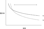
- the optically anisotropic film of the present invention has anti-wavelength dispersibility. Is easy to show. That is, as shown in FIG. 4, since the refractive index of nx of the optically anisotropic film decreases earlier than that of ny, the refractive index of nx decreases more slowly than ny in the region indicated by the arrow. Therefore, the inverse wavelength dispersibility is easily achieved.
- the optically anisotropic film contains a rod-shaped compound and a plate-shaped compound
- the effects of the present invention are more excellent, and preferred embodiments of the optically anisotropic film include aspects 1 to 7 shown in Table 1.
- Manner in 1-7 in each of the optical anisotropic film the degree of orientation of the Nz R, D R, rod-like compounds of the rod-like compound of rod-shaped compound, Nz P of the plate-like compounds, D P of the plate-like compounds, plate The degree of orientation of the compound and the content ratio (mass%) of the plate-shaped compound to the total amount of the plate-shaped compound and the rod-shaped compound are shown.
- Nz R is from 0.98 to 1.02 of the rod-shaped compound
- the D P is 1.08 to 1.12 (preferably rod-shaped compound, 1.09 to 1 .11)
- the degree of orientation of the rod-shaped compound is 0.65 to 0.72
- the Nz P of the plate-shaped compound is -0.25 to -0.15 (preferably -0.25 to -0.19)
- D P is 1.20 to 1.24 of Jo compound content is 41 to 44 mass of the plate-like compounds to the total amount of orientation is from 0.65 to 0.72, the plate-like compounds and rod-shaped compound plate compound %.
- Requirement 1 The maximum absorption wavelength of the rod-like compound is 250nm or more, or, D R of the rod-like compound is from 1.09 to 1.11.
- Requirement 2 Nz P is -0.25 to -0.19, or the degree of orientation of the rod-shaped compound and the degree of orientation of the plate-shaped compound are both 0.65 to 0.72.
- the composition may contain other components other than the rod-shaped compound and the plate-shaped compound.
- the composition may contain a salt (a salt consisting of a cation and an anion).
- a salt a salt consisting of a cation and an anion.
- the plate-like compound has an acid group or a salt thereof, if the composition contains a salt, the planes in the plate-like compound are more likely to associate with each other, and a column-like aggregate is formed. Easy to form.
- the salt does not include the rod-shaped compound and the plate-shaped compound. That is, the salt is a compound different from the rod-shaped compound and the plate-shaped compound.
- the salt is not particularly limited, and may be an inorganic salt or an organic salt, and the inorganic salt is preferable in that the effect of the present invention is more excellent.
- the inorganic salt include an alkali metal salt, an alkaline earth metal salt, and a transition metal salt, and the alkali metal salt is preferable in that the effect of the present invention is more excellent.
- the alkali metal salt is a salt in which the cation is an alkali metal ion, and the alkali metal ion is preferably lithium ion or sodium ion, and more preferably lithium ion. That is, as the salt, a lithium salt or a sodium salt is preferable, and a lithium salt is more preferable.
- alkali metal salt examples include alkali metal hydroxides such as lithium hydroxide, sodium hydroxide, and potassium hydroxide; alkali metal carbonates such as lithium carbonate, sodium carbonate, and potassium carbonate; hydrogen carbonate.
- alkali metal bicarbonates such as lithium, sodium hydrogen carbonate, and potassium hydrogen carbonate;
- the alkali metal salt may be, for example, a phosphate or a chloride.
- anion of the salt examples include hydroxide ion, carbonate ion, chloride ion, sulfate ion, nitrate ion, phosphate ion, borate ion, tetrafluoroborate ion, hexafluorophosphate ion and perchlorate ion.
- the cation in the acid group salt and the cation in the salt used are of the same type.
- the composition may contain a solvent.
- the solvent include water, polar solvents such as alcohol and dimethylformamide, and non-polar solvents such as hexane. Of these, polar solvents are preferred, and water or alcohol is more preferred.
- the additives that may be contained in the composition include polymerizable compounds, polymerization initiators, wavelength dispersion control agents, optical property adjusters, surfactants, adhesion improvers, slip agents, and orientation control. Agents and UV absorbers may be mentioned.
- the composition comprises at least a lyotropic liquid crystal compound.
- the composition corresponds to a lyotropic liquid crystal composition.
- the lyotropic liquid crystal composition is a composition having a property of causing a phase transition between an isotropic phase and a liquid crystal phase by changing the temperature and concentration in a solution state. That is, the composition is a composition capable of exhibiting lyotropic liquid crystallinity by adjusting the concentration of each compound in a solution state containing various components such as a rod-shaped compound, a plate-shaped compound, and a solvent.
- the composition Even if the composition contains an excess solvent and does not exhibit lyotropic liquid crystallinity in that state, it exhibits lyotropic liquid crystallinity when the concentration changes, such as when the composition exhibits lyotropic liquid crystallinity in the drying step after application of the composition.
- the composition corresponds to the above-mentioned lyotropic liquid crystal composition.
- the content of the lyotropic liquid crystal compound in the composition is not particularly limited, but is preferably 60 to 100% by mass, more preferably 80 to 99% by mass, based on the total solid content in the composition.
- the total solid content means a component capable of forming an optically anisotropic film, excluding a solvent. Even if the properties of the above components are liquid, they are calculated as solid content.
- the content of the rod-shaped compound with respect to the total mass of the rod-shaped compound and the plate-shaped compound is not particularly limited, but more than 50% by mass is preferable from the viewpoint of excellent effects of the present invention. , 55% by mass or more is more preferable.
- the upper limit is not particularly limited, but 90% by mass or less is preferable, and 80% by mass is more preferable.
- the composition may contain only one kind of rod-shaped compound, or may contain two or more kinds of rod-shaped compounds.
- the composition may contain only one kind of plate-like compound, or may contain two or more kinds of plate-like compounds.
- the salt content is not particularly limited, but the ratio W determined by the formula (W) is preferably 0.25 to 1.75 in that the effect of the present invention is more excellent. It is more preferably 0.50 to 1.50, and even more preferably 0.75 to 1.15.
- C1 represents the molar amount of the cation contained in the salt of the acid group contained in the rod-shaped compound.
- the above C1 is set to 0.
- C2 represents the molar amount of cation contained in the salt of the acid group contained in the plate-like compound.
- the above C2 is set to 0.
- C3 represents the molar amount of cations contained in the salt.
- A1 represents the total molar amount of the acid group or the salt thereof contained in the rod-shaped compound.
- the total molar amount represents the sum of the molar amount of the acid group and the molar amount of the salt of the acid group.
- the molar amount of the one not contained is set to 0.
- A2 represents the total molar amount of the acid group or the salt thereof contained in the plate compound.
- the total molar amount represents the sum of the molar amount of the acid group and the molar amount of the salt of the acid group.
- the plate-like compound has only one of an acid group and a salt of the acid group, the molar amount of the one not contained is set to 0.
- a rod-like compound having a SO 3 Li group, a plate-shaped compound having a SO 3 Li group, in a composition comprising a LiOH, molar amount of SO 3 Li groups rodlike compound has is 5 mmol
- plate-like compounds When the molar amount of SO 3 Li group contained in is 8 mmol and the molar amount of LiOH is 8 mmol, the molar amount of cation contained in the salt of the acid group contained in the rod-shaped compound is 5 mmol, and the molar amount of the acid group contained in the plate-shaped compound is 5 mmol.
- the molar amount of the cation contained in the salt is calculated to be 8 mmol
- the molar amount of the cation contained in LiOH is calculated to be 8 mmol
- the rodlike compound is a rod-like compound having a SO 3 H group
- the above ratio W represents the amount of cations derived from the excess salt in the composition with respect to the acid group of the plate compound or the salt thereof. That is, the ratio W represents the ratio of the acid group of the rod-shaped compound and the plate-shaped compound in the composition to the excess amount of cations that do not form a salt with respect to the acid group of the plate-shaped compound or a salt thereof.
- the composition contains a predetermined amount of cation with respect to the acid group of the plate-shaped compound or a salt thereof, the plate-shaped compound tends to have a predetermined structure in the optically anisotropic film, and the desired optically anisotropic substance is easily formed. A film is easily obtained.
- the mass ratio of the salt content to the content of the plate-like compound in the composition is not particularly limited, but is preferably 0.010 to 0.200, preferably 0.025 to 0.150. Is more preferable.
- the composition may contain a solvent as described above.
- the solid content concentration of the composition is not particularly limited, but is preferably 1 to 50% by mass, more preferably 3 to 30% by mass, based on the total mass of the composition, from the viewpoint of excellent effects of the present invention.
- the composition is a lyotropic liquid crystal composition. Therefore, the composition may contain a predetermined amount of solvent and exhibit lyotropic liquid crystallinity (a state in which lyotropic liquid crystallinity is exhibited), or may contain an excess of solvent, and in that state.
- the solvent volatilizes when the optically anisotropic film is formed, and the composition exhibits lyotropic liquid crystallinity during the formation of the coating film. There may be.
- an alignment film is arranged on the support, the orientation of the compound is induced by exhibiting lyotropic liquid crystallinity in the drying process after application of the composition, and the optical anisotropy is induced. It becomes possible to form a film.
- the method for producing an optically anisotropic film of the present invention is not particularly limited as long as the above-mentioned composition is used.
- a method of applying a composition and orienting a lyotropic liquid crystal compound (for example, a rod-shaped compound and a plate-shaped compound) in a coating film to form an optically anisotropic film is preferable.
- a lyotropic liquid crystal compound for example, a rod-shaped compound and a plate-shaped compound
- the composition is applied.
- the support used is a member that functions as a substrate for applying the composition.
- the support may be a so-called temporary support.
- the support temporary support
- the material constituting the plastic substrate include polyester resin such as polyethylene terephthalate, polycarbonate resin, (meth) acrylic resin, epoxy resin, polyurethane resin, polyamide resin, polyolefin resin, cellulose resin, silicone resin, and polyvinyl alcohol. ..
- the thickness of the support may be about 5 to 1000 ⁇ m, preferably 10 to 250 ⁇ m, and more preferably 15 to 90 ⁇ m.
- an alignment film may be arranged on the support.
- the alignment film generally contains a polymer as a main component.
- the polymer for an alignment film has been described in a large number of documents, and a large number of commercially available products are available.
- As the polymer for the alignment film polyvinyl alcohol, polyimide, or a derivative thereof is preferable. It is preferable that the alignment film is subjected to a known rubbing treatment. Further, as the alignment film, a photoalignment film may be used.
- the thickness of the alignment film is preferably 0.01 to 10 ⁇ m, more preferably 0.01 to 1 ⁇ m.
- Examples of the coating method include known methods, such as a curtain coating method, an extrusion coating method, a roll coating method, a dip coating method, a spin coating method, a print coating method, a spray coating method, and a slide coating method. Further, if a coating method of applying shearing is adopted, two treatments of compound orientation and coating can be performed at the same time. Further, by continuous coating, the lyotropic liquid crystal compound may be continuously oriented at the same time as coating. Examples of continuous coating include a curtain coating method, an extrusion coating method, a roll coating method, and a slide coating method. As a specific coating means, it is preferable to use a die coater, a blade coater, or a bar coater.
- lyotropic liquid crystal compounds for example, rod-shaped compounds and plate-shaped compounds
- a method of applying shearing can be mentioned. As described above, when the rod-shaped compound and the plate-shaped compound are used, the orientation state as shown in FIG. 1 can be taken.
- the coating film formed on the support may be heat-treated.
- the conditions for heating the coating film are not particularly limited, but the heating temperature is preferably 50 to 250 ° C., and the heating time is preferably 10 seconds to 10 minutes. Further, after heating the coating film, the coating film may be cooled if necessary.
- the cooling temperature is preferably 20 to 200 ° C, more preferably 20 to 150 ° C.
- a method using an alignment film can be mentioned.
- the concentration of the solvent in the composition used is not particularly limited, and the concentration of the solvent may be such that the composition exhibits lyotropic liquid crystallinity, or the concentration may be lower than that. May be good.
- the composition is a lyotropic liquid crystal composition
- the composition is applied even when the concentration of the solvent in the composition is high (when the composition itself shows an isotropic phase).
- the orientation of the compound is induced on the alignment film, and an optically anisotropic film can be formed.
- a treatment for fixing the orientation state of the lyotropic liquid crystal compound may be carried out, if necessary.
- the method of fixing the orientation state of the lyotropic liquid crystal compound is not particularly limited, and examples thereof include a method of heating and then cooling the coating film as described above.
- a solution containing polyvalent metal ions and a formed coating film are used as a method for fixing the orientation state of the lyotropic liquid crystal compound. There is a method of contacting. When the solution containing the polyvalent metal ions is brought into contact with the formed coating film, the polyvalent metal ions are supplied into the coating film.
- the polyvalent metal ions supplied into the coating film serve as cross-linking points between the acid groups of the rod-shaped compound and / or the plate-shaped compound or salts thereof, a cross-linked structure is formed in the coating film, and the orientation of the lyotropic liquid crystal compound is formed.
- the state is fixed.
- the type of polyvalent metal ion used is not particularly limited, and an alkaline earth metal ion is preferable, and a calcium ion is more preferable, in that the orientation state of the lyotropic liquid crystal compound is easily fixed.
- the above-mentioned optically anisotropic film can be applied to various uses.
- the in-plane retardation of the optically anisotropic film can be adjusted and used as a so-called ⁇ / 4 plate or ⁇ / 2 plate.
- the ⁇ / 4 plate is a plate having a function of converting linearly polarized light having a specific wavelength into circularly polarized light (or converting circularly polarized light into linearly polarized light). More specifically, it is a plate showing an in-plane retardation Re of ⁇ / 4 (or an odd multiple of this) at a predetermined wavelength of ⁇ nm.
- the in-plane retardation (Re (550)) of the ⁇ / 4 plate at a wavelength of 550 nm may have an error of about 25 nm centered on the ideal value (137.5 nm), and may be, for example, 110 to 160 nm. It is preferably 120 to 150 nm, and more preferably 120 to 150 nm.
- the ⁇ / 2 plate refers to an optically anisotropic film in which the in-plane retardation Re ( ⁇ ) at a specific wavelength ⁇ nm satisfies Re ( ⁇ ) ⁇ / 2. This equation may be achieved at any wavelength in the visible light region (eg, 550 nm). Above all, it is preferable that the in-plane retardation Re (550) at a wavelength of 550 nm satisfies the following relationship. 210nm ⁇ Re (550) ⁇ 300nm
- the optically anisotropic film may be used as an optical film in combination with other layers. That is, the optical film of the present invention includes the above-mentioned optically anisotropic film and other layers. Examples of the other layer include the above-mentioned alignment film and the support.
- the position of the optically anisotropic film in the optical film is not particularly limited, and examples thereof include an embodiment in which the support, the alignment film, and the optically anisotropic film are provided in this order.
- the optically anisotropic film of the present invention can be suitably applied to a polarizing plate.
- the polarizing plate of the present invention preferably a circular polarizing plate
- the circularly polarizing plate is an optical element that converts unpolarized light into circularly polarized light.
- the polarizing element may be any member (linearly polarized light) having a function of converting light into specific linearly polarized light, and an absorption type polarizer can be mainly used.
- the absorption type polarizer examples include an iodine-based polarizer, a dye-based polarizer using a dichroic dye, and a polyene-based polarizer.
- the iodine-based polarizing element and the dye-based polarizer include a coating type polarizing element and a stretching type polarizing element, both of which can be applied, but they are produced by adsorbing iodine or a dichroic dye on polyvinyl alcohol and stretching the polarizing element. Polarizers are preferred.
- the relationship between the slow axis of the optically anisotropic film and the absorption axis of the polarizer is not particularly limited, but when the optically anisotropic film is a ⁇ / 4 plate and the optical film is used as a circularly polarizing film, it is optical.
- the angle formed by the in-plane slow axis of the anisotropic film and the absorption axis of the polarizer is preferably in the range of 45 ⁇ 10 °. That is, the angle formed by the in-plane slow-phase axis of the optically anisotropic film and the absorption axis of the polarizer is preferably in the range of 35 to 55 °.
- the circularly polarizing plate of the present invention can be suitably applied to a display device. That is, the circularly polarizing plate of the present invention can be suitably used as a so-called antireflection film.
- the display device of the present invention has a display element and the above-mentioned circularly polarizing plate.
- the circularly polarizing plate is arranged on the viewing side, and the polarizer is arranged on the viewing side in the circularly polarizing plate.
- the display device is not particularly limited, and examples thereof include an organic EL display element and a liquid crystal display element, and an organic EL display element is preferable.
- each of the non-colorable rod-shaped compounds I-1 to I-5 is a polymer (n is 2 or more), the number average molecular weight of the non-colorable rod-shaped compound I-1 is 24,000, and the molecular weight distribution is 6.
- the number average molecular weight of the non-coloring rod compound I-2 is 27,000, the molecular weight distribution is 5.8, and the number average molecular weight of the non-coloring rod compound I-3 is 20,000.
- the distribution is 6.1
- the non-coloring rod compound I-4 has a number average molecular weight of 25,000
- the molecular weight distribution is 6.5
- the non-coloring rod compound I-5 has a number average molecular weight of 25, At 000, the molecular weight distribution was 5.1.
- the non-colorable rod-shaped compounds I-1 to I-5 and the non-colorable plate-shaped compounds II-1 to II-3 all exhibited lyotropic liquid crystallinity. Further, the non-colorable rod-shaped compounds I-1 to I-5 and the non-colorable plate-like compounds II-1 to II-3 all satisfied the above-mentioned non-colorable requirements.
- the ultraviolet-visible absorption spectrum of the solution in which each of the above compounds is dissolved is measured at a concentration such that the absorbance at the maximum absorption wavelength in the ultraviolet region (230 to 400 nm) is 1.0, the visible light region The absorbance in the range (wavelength 400 to 700 nm) was 0.1 or less.
- the non-colorable rod-like compound I-1 had a maximum absorption wavelength at 260 nm in the wavelength range of 230 to 400 nm.
- the non-colorable rod compound I-2 had a maximum absorption wavelength at 260 nm in the wavelength range of 230 to 400 nm.
- the non-colorable rod-like compound I-3 had a maximum absorption wavelength at 240 nm in the wavelength range of 230 to 400 nm.
- the non-colorable rod-like compound I-4 had a maximum absorption wavelength at 240 nm in the wavelength range of 230 to 400 nm.
- the non-colorable rod compound I-5 had a maximum absorption wavelength at 290 nm in the wavelength range of 230 to 400 nm.
- the non-colorable plate-like compound II-1 had a maximum absorption wavelength at 345 nm in the wavelength range of 230 to 400 nm.
- the non-colorable plate-like compound II-2 had a maximum absorption wavelength at 350 nm in the wavelength range of 230 to 400 nm.
- the non-colorable plate-like compound II-3 had a maximum absorption wavelength at 345 nm in the wavelength range of 230 to 400 nm.
- composition 1 for forming an optically anisotropic film having the following composition was prepared.
- the composition 1 for forming an optically anisotropic film was a composition exhibiting lyotropic liquid crystallinity.
- Composition for forming an optically anisotropic film 1 ⁇
- Non-colorable rod compound I-1 5.6 parts by mass
- Non-colorable plate compound II-1 4.4 parts by mass
- composition 1 for forming an optically anisotropic film prepared above was applied on a glass substrate as a base material with a wire bar (moving speed: 100 cm / s), and then naturally dried at room temperature (20 ° C.). Next, the obtained coating film was immersed in a 1 mol / L calcium chloride aqueous solution for 5 seconds, washed with ion-exchanged water, and air-dried to fix the orientation state, whereby the optically anisotropic film 1 was formed. Made.
- Examples 2 to 9 Comparative Examples 3 to 6> The same method as in Example 1 except that the non-colorable rod-shaped compound or the non-colorable plate-like compound was changed to the compound shown in Table 2 below and the amount of lithium hydroxide used was adjusted as shown in Table 2 below. Then, optically anisotropic films 2 to 9 and C3 to C6 were prepared.
- composition C1 for forming an optically anisotropic film having the following composition was prepared.
- the composition for forming an optically anisotropic film C1 was a composition exhibiting lyotropic liquid crystallinity.
- Composition for forming an optically anisotropic film C1 ⁇
- Non-colorable rod-shaped compound I-5 1.6 parts by mass
- Non-colorable plate-like compound II-5 8.4 parts by mass
- An optically anisotropic film C1 was prepared on a glass substrate as a base material by the same method as in Example 1.
- the Re (550) of the optically anisotropic film produced in Examples 1 to 9 and Comparative Examples 1 to 7 was 142 nm.
- the obtained circularly polarizing plate was bonded to the mirror surface using an adhesive so that the ITO thin film side faced the mirror surface to prepare a test piece.
- the obtained test piece mimics the form in which a circularly polarizing plate composed of an optically anisotropic film and a polarizer is arranged on an organic EL display element having an ITO electrode.
- the reflected light was visually observed from the licking of this test piece under a fluorescent lamp, and the black spot was evaluated according to the following evaluation criteria.
- B The blackness is strong and the screen looks strong.
- C There is a gray tint, and the screen is not tight.
- D The gray color is strong and the screen does not feel tight.
- D R column shows the wavelength dispersion D R of the formula (R) of the rod-like compound described above.
- Method of measuring the chromatic dispersion D R is as described above.
- the optically anisotropic film R is produced by the method described above using a mixed solution R obtained by mixing the non-colorable rod-shaped compound I-1 (10 parts by mass) and water (90 parts by mass). and prepared to give a wavelength dispersion D R.
- the “ ⁇ R ” column represents the maximum absorption wavelength of the rod-shaped compound.
- D P column indicates the wavelength dispersion D P of the formula (P) of the plate-like compounds described above.
- the “ ⁇ P ” column represents the maximum absorption wavelength of the plate-like compound.
- Method of measuring the wavelength dispersion D P and Nz P are as described above.
- a mixed solution obtained by mixing the non-colorable plate-like compound II-1 (10 parts by mass), water (90 parts by mass), and lithium hydroxide (0.59 parts by mass). P2 and produce an optical anisotropic film P by the method described above was used to obtain a wavelength dispersion D P and Nz P.
- the "ratio W” column represents the ratio W obtained by the above formula (W).
- the "degree of orientation of the rod-shaped compound” and the “degree of orientation of the plate-shaped compound” represent the degree of orientation of the rod-shaped compound and the plate-shaped compound in the optically anisotropic film as described above.
- the method of calculating the degree of orientation is as described above.
- the optically anisotropic film of the present invention showed a predetermined effect. Further, as compared with Examples 1 to 9, when the Re (450) / Re (550) of the optically anisotropic film was 0.76 to 0.86, a more excellent effect was obtained. Further, from the comparison of Examples 1 to 3, a more excellent effect was obtained when the maximum absorption wavelength of the rod-shaped compound was 250 nm or more. Further, from the comparison of Examples 1 to 9, more excellent effects were obtained when the following requirements 1 and 2 were satisfied.
- Requirement 1 The maximum absorption wavelength of the rod-like compound is 250nm or more, or, D R of the rod-like compound is from 1.09 to 1.11.
- Requirement 2 Nz P is -0.25 to -0.19, or the degree of orientation of the rod-shaped compound and the degree of orientation of the plate-shaped compound are both 0.65 to 0.72.
- the optically anisotropic film of the present invention showed a predetermined effect.
Abstract
The present invention provides: an optical anisotropic film that is combined with a polarizer and positioned on a display element as a circularly polarizing plate, the optical anisotropic film having excellent firmness of black when the resultant display device is viewed from an oblique direction; a circularly polarizing plate; and a display device. This optical anisotropic film is formed using a composition that contains a lyotropic liquid-crystalline compound having non-discoloration properties, wherein an Nz factor of the optical anisotropic film satisfies the relationship in formula (1), and the optical anisotropic film satisfies the relationship in formula (2). Formula (1): 0.40≤Nz factor≤0.60 Formula (2): 0.60≤Re(450)/Re(550)≤0.90 Re(450) represents the in-plane retardation of the optical anisotropic film at a wavelength of 450 nm. Re(550) represents the in-plane retardation of the optical anisotropic film at a wavelength of 550 nm.
Description
本発明は、光学異方性膜、円偏光板、および、表示装置に関する。
The present invention relates to an optically anisotropic film, a circularly polarizing plate, and a display device.
屈折率異方性を持つ位相差膜(光学異方性膜)は、表示装置の反射防止膜、および、液晶表示装置の光学補償フィルムなどの種々の用途に適用されている。
例えば、特許文献1においては、加熱により液晶相を形成するサーモトロピック液晶性を示す化合物を用いて作製されたλ/板およびポジティブCプレートを含む積層体(光学異方性膜に該当)が開示されている。 A retardation film having a refractive index anisotropy (optical anisotropy film) is applied to various applications such as an antireflection film for a display device and an optical compensation film for a liquid crystal display device.
For example,Patent Document 1 discloses a laminate (corresponding to an optically anisotropic film) containing a λ / plate and a positive C plate prepared by using a compound exhibiting thermotropic liquid crystal properties that forms a liquid crystal phase by heating. Has been done.
例えば、特許文献1においては、加熱により液晶相を形成するサーモトロピック液晶性を示す化合物を用いて作製されたλ/板およびポジティブCプレートを含む積層体(光学異方性膜に該当)が開示されている。 A retardation film having a refractive index anisotropy (optical anisotropy film) is applied to various applications such as an antireflection film for a display device and an optical compensation film for a liquid crystal display device.
For example,
光学異方性膜は、有機エレクトロルミネッセンス(EL)表示装置などに代表される表示装置の反射防止用の円偏光板の部材として用いられる場合がある。
本発明者らは、特許文献1に記載される部材を円偏光板の光学異方性膜として用いて、得られた円偏光板を表示装置に適用して、その特性を評価したところ、斜め方向から視認した際の黒しまりが十分でなく、更なる改良が必要であることを知見した。
なお、黒しまりが良好であるとは、黒味が強いことを意味する。 The optically anisotropic film may be used as a member of a circularly polarizing plate for antireflection of a display device represented by an organic electroluminescence (EL) display device or the like.
The present inventors used the member described inPatent Document 1 as an optically anisotropic film of a circularly polarizing plate, applied the obtained circularly polarizing plate to a display device, and evaluated its characteristics. It was found that the blackening when visually recognized from the direction was not sufficient, and further improvement was necessary.
It should be noted that a good blackness means a strong blackness.
本発明者らは、特許文献1に記載される部材を円偏光板の光学異方性膜として用いて、得られた円偏光板を表示装置に適用して、その特性を評価したところ、斜め方向から視認した際の黒しまりが十分でなく、更なる改良が必要であることを知見した。
なお、黒しまりが良好であるとは、黒味が強いことを意味する。 The optically anisotropic film may be used as a member of a circularly polarizing plate for antireflection of a display device represented by an organic electroluminescence (EL) display device or the like.
The present inventors used the member described in
It should be noted that a good blackness means a strong blackness.
本発明は、上記実情に鑑みて、偏光子と組み合わせて円偏光板として表示素子上に配置して、得られた表示装置を斜め方向から視認した際の黒しまりが良好である、光学異方性膜を提供することを課題とする。
また、本発明は、円偏光板、および、表示装置を提供することも課題とする。 In view of the above circumstances, the present invention is arranged on a display element as a circularly polarizing plate in combination with a polarizing element, and the obtained display device has good blackening when visually recognized from an oblique direction. The subject is to provide a sex membrane.
Another object of the present invention is to provide a circularly polarizing plate and a display device.
本発明者らは、従来技術の問題点について鋭意検討した結果、以下の構成により上記課題を解決できることを見出した。
As a result of diligent studies on the problems of the prior art, the present inventors have found that the above problems can be solved by the following configuration.
(1) 非着色性のリオトロピック液晶性化合物を含む組成物を用いて形成された光学異方性膜であって、
光学異方性膜のNzファクターが後述する式(1)の関係を満たし、
光学異方性膜が後述する式(2)の関係を満たす、光学異方性膜。
(2) 組成物が、非着色性のリオトロピック液晶性棒状化合物、および、非着色性のリオトロピック液晶性板状化合物を含む、(1)に記載の光学異方性膜。
(3) 非着色性のリオトロピック液晶性棒状化合物が波長300nm以下の範囲に極大吸収波長を有し、
非着色性のリオトロピック液晶性板状化合物が波長300nm超の範囲に極大吸収波長を有する、(2)に記載の光学異方性膜。
(4) 非着色性のリオトロピック液晶性棒状化合物の後述する式(R)で表される波長分散性DRが1.05以上1.20未満である、(2)または(3)に記載の光学異方性膜。
(5) 非着色性のリオトロピック液晶性板状化合物の後述する式(P)で表される波長分散性DPが1.20~1.30である、(2)~(4)のいずれかに記載の光学異方性膜。
(6) 光学異方性膜PのNzファクターが-0.60~-0.01である、(5)に記載の光学異方性膜。
(7) 非着色性のリオトロピック液晶性棒状化合物が、後述する式(X)で表される繰り返し単位を有する高分子である、(2)~(6)のいずれかに記載の光学異方性膜。
(8) 非着色性のリオトロピック液晶性板状化合物が、後述する式(Y)で表される化合物である、(2)~(7)のいずれかに記載の光学異方性膜。
(9) (1)~(8)のいずれかに記載の光学異方性膜と、
偏光子と、を有する、円偏光板。
(10) 光学異方性膜の面内の遅相軸と、偏光子の吸収軸とのなす角が、45±5°の範囲内である、(9)に記載の円偏光板。
(11) (9)または(10)に記載の円偏光板と、
表示素子と、を有する表示装置。
(12) 表示素子が、有機エレクトロルミネッセンス表示素子である、(11)に記載の表示装置。 (1) An optically anisotropic film formed by using a composition containing a non-colorable lyotropic liquid crystal compound.
The Nz factor of the optically anisotropic film satisfies the relationship of the formula (1) described later, and
An optically anisotropic film in which the optically anisotropic film satisfies the relationship of the formula (2) described later.
(2) The optically anisotropic film according to (1), wherein the composition comprises a non-colorable lyotropic liquid crystal rod-like compound and a non-colorable lyotropic liquid crystal plate-like compound.
(3) The non-colorable lyotropic liquid crystal rod-like compound has a maximum absorption wavelength in the wavelength range of 300 nm or less, and has a maximum absorption wavelength.
The optically anisotropic film according to (2), wherein the non-colorable lyotropic liquid crystal plate-like compound has a maximum absorption wavelength in a wavelength range of more than 300 nm.
(4) is less than the wavelength dispersion D R 1.05 1.20 represented by the later-described equation of the non-coloring properties of the lyotropic liquid crystalline rod-like compound (R), according to (2) or (3) Optically anisotropic film.
(5) a wavelength dispersion D P of 1.20 - 1.30 the formula (P) to be described later of the non-coloring properties of the lyotropic liquid crystalline plate compound, or (2) to (4) The optically anisotropic film according to.
(6) The optically anisotropic film according to (5), wherein the Nz factor of the optically anisotropic film P is −0.60 to −0.01.
(7) The optical anisotropy according to any one of (2) to (6), wherein the non-colorable lyotropic liquid crystal rod-shaped compound is a polymer having a repeating unit represented by the formula (X) described later. film.
(8) The optically anisotropic film according to any one of (2) to (7), wherein the non-colorable lyotropic liquid crystal plate-like compound is a compound represented by the formula (Y) described later.
(9) The optically anisotropic film according to any one of (1) to (8) and
A circularly polarizing plate having a polarizer.
(10) The circularly polarizing plate according to (9), wherein the angle formed by the in-plane slow-phase axis of the optically anisotropic film and the absorption axis of the polarizer is within the range of 45 ± 5 °.
(11) With the circularly polarizing plate according to (9) or (10),
A display device having a display element.
(12) The display device according to (11), wherein the display element is an organic electroluminescence display element.
本発明によれば、偏光子と組み合わせて円偏光板として表示素子上に配置して、得られた表示装置を斜め方向から視認した際の黒しまりが良好である、光学異方性膜を提供できる。
また、本発明によれば、円偏光板、および、表示装置を提供できる。 According to the present invention, there is provided an optically anisotropic film which is arranged on a display element as a circularly polarizing plate in combination with a polarizing element and has good blackening when the obtained display device is visually recognized from an oblique direction. can.
Further, according to the present invention, a circularly polarizing plate and a display device can be provided.
以下、本発明について詳細に説明する。
なお、本明細書において「~」を用いて表される数値範囲は、「~」の前後に記載される数値を下限値および上限値として含む範囲を意味する。
また、遅相軸および進相軸は、特別な断りがなければ、波長550nmにおける定義である。つまり、特別な断りがない限り、例えば、遅相軸方向という場合、波長550nmにおける遅相軸の方向を意味する。 Hereinafter, the present invention will be described in detail.
The numerical range represented by using "-" in the present specification means a range including the numerical values before and after "-" as the lower limit value and the upper limit value.
Further, the slow phase axis and the advance phase axis are defined at a wavelength of 550 nm unless otherwise specified. That is, unless otherwise specified, for example, the slow-phase axis direction means the direction of the slow-phase axis at a wavelength of 550 nm.
本発明において、Re(λ)およびRth(λ)は各々、波長λにおける面内のレタデーションおよび厚み方向のレタデーションを表す。特に記載がないときは、波長λは、550nmとする。
本発明において、Re(λ)およびRth(λ)はAxoScan OPMF-1(オプトサイエンス社製)において、波長λで測定した値である。AxoScanにて平均屈折率((nx+ny+nz)/3)と膜厚(d(μm))を入力することにより、
遅相軸方向(°)
Re(λ)=R0(λ)
Rth(λ)=((nx+ny)/2-nz)×d
が算出される。
なお、R0(λ)は、AxoScan OPMF-1で算出される数値として表示されるものであるが、Re(λ)を意味している。 In the present invention, Re (λ) and Rth (λ) represent in-plane retardation and thickness direction retardation at wavelength λ, respectively. Unless otherwise specified, the wavelength λ is 550 nm.
In the present invention, Re (λ) and Rth (λ) are values measured at a wavelength λ in AxoScan OPMF-1 (manufactured by Optoscience). By inputting the average refractive index ((nx + ny + nz) / 3) and film thickness (d (μm)) in AxoScan,
Slow phase axial direction (°)
Re (λ) = R0 (λ)
Rth (λ) = ((nx + ny) /2-nz) × d
Is calculated.
Although R0 (λ) is displayed as a numerical value calculated by AxoScan OPMF-1, it means Re (λ).
本明細書において、屈折率nx、ny、および、nzは、アッベ屈折計(NAR-4T、アタゴ(株)製)を使用し、光源にナトリウムランプ(λ=589nm)を用いて測定する。また、波長依存性を測定する場合は、多波長アッベ屈折計DR-M2(アタゴ(株)製)にて、干渉フィルタとの組み合わせで測定できる。
また、ポリマーハンドブック(JOHN WILEY&SONS,INC)、および、各種光学フィルムのカタログの値を使用できる。主な光学フィルムの平均屈折率の値を以下に例示する:セルロースアシレート(1.48)、シクロオレフィンポリマー(1.52)、ポリカーボネート(1.59)、ポリメチルメタクリレート(1.49)、および、ポリスチレン(1.59)。 In the present specification, the refractive indexes nx, ny, and nz are measured using an Abbe refractometer (NAR-4T, manufactured by Atago Co., Ltd.) and a sodium lamp (λ = 589 nm) as a light source. Further, when measuring the wavelength dependence, it can be measured with a multi-wavelength Abbe refractometer DR-M2 (manufactured by Atago Co., Ltd.) in combination with an interference filter.
In addition, the values in the Polymer Handbook (JOHN WILEY & SONS, INC) and the catalogs of various optical films can be used. The values of the average refractive index of the main optical films are illustrated below: cellulose acylate (1.48), cycloolefin polymer (1.52), polycarbonate (1.59), polymethylmethacrylate (1.49), And polystyrene (1.59).
また、本明細書において、Nzファクターとは、Nz=(nx-nz)/(nx-ny)で与えられる値である。
光学異方性膜のNzファクターを算出する際のnxは、光学異方性膜の面内の遅相軸方向の屈折率であり、光学異方性膜のNzファクターを算出する際のnyは光学異方性膜の面内の進相軸方向の屈折率であり、光学異方性膜のNzファクターを算出する際のnzは光学異方性膜の厚み方向の屈折率である。
なお、Nzファクターを算出する際のnx、ny、および、nzは、波長550nmにおける各屈折率である。 Further, in the present specification, the Nz factor is a value given by Nz = (nx-nz) / (nx-ny).
Nx when calculating the Nz factor of the optically anisotropic film is the refraction coefficient in the slow axis direction in the plane of the optically anisotropic film, and ny when calculating the Nz factor of the optically anisotropic film is It is the in-plane refractive index of the optically anisotropic film, and nz when calculating the Nz factor of the optically anisotropic film is the refractive index in the thickness direction of the optically anisotropic film.
In addition, nx, ny, and nz when calculating the Nz factor are each refractive index at a wavelength of 550 nm.
なお、本明細書では、「可視光線」とは、波長400~700nmの光を意図する。また、「紫外線」とは、波長10nm以上400nm未満の光を意図する。
また、本明細書において、角度の関係(例えば、「直交」、「平行」等)については、本発明が属する技術分野において許容される誤差の範囲を含むものとする。例えば、厳密な角度±5°の範囲内であることなどを意味し、厳密な角度との誤差は、±3°の範囲内であることが好ましい。 In the present specification, "visible light" is intended to be light having a wavelength of 400 to 700 nm. Further, "ultraviolet rays" are intended to be light having a wavelength of 10 nm or more and less than 400 nm.
Further, in the present specification, the relationship of angles (for example, "orthogonal", "parallel", etc.) shall include a range of errors allowed in the technical field to which the present invention belongs. For example, it means that the angle is within the range of ± 5 °, and the error from the exact angle is preferably within the range of ± 3 °.
本明細書において表記される2価の基(例えば、-COO-)の結合方向は特に制限されず、例えば、X-L-Y中のLが-COO-である場合、X側に結合している位置を*1、Y側に結合している位置を*2とすると、Lは*1-O-CO-*2であってもよく、*1-CO-O-*2であってもよい。
The bonding direction of the divalent group (for example, -COO-) described in the present specification is not particularly limited. For example, when L in X-LY is -COO-, it is bonded to the X side. If the position is * 1 and the position connected to the Y side is * 2, L may be * 1-O-CO- * 2 or * 1-CO-O- * 2. May be good.
本発明の光学異方性膜は、リオトロピック液晶性化合物を用いて形成され、所定の光学特性を示す。
本発明の効果が得られる理由は、以下のように考えられる。
本発明者らは、従来の円偏光板を使用した場合に黒しまりが不十分である原因は表示素子で反射された光の影響によるものと考え、リオトロピック液晶性化合物を採用した。リオトロピック液晶性化合物は、通常、サーモトロピック液晶性化合物と異なり、アルキル基などの柔軟な基を有さずに液晶性を示すため、リオトロピック液晶性化合物を用いて形成された光学異方性膜はアルキル基などの屈折率を低下させる基を含まないため、比較的高い屈折率を示しやすい。このような屈折率が高い光学異方性膜を表示素子上に配置されることにより、表示素子、光学異方性膜、および、偏光子の順に徐々に屈折率が低くなる構成となり、上記構成に由来する干渉を利用した反射防止機能が働き、黒しまりに寄与していると考えられる。
また、光学異方性膜が所定の光学特性(所定のNzファクターの範囲、所定のRe(450)/Re(550)の範囲)を満たすことにより、より黒しまりが良好になっていると考えられる。 The optically anisotropic film of the present invention is formed by using a lyotropic liquid crystal compound and exhibits predetermined optical characteristics.
The reason why the effect of the present invention can be obtained is considered as follows.
The present inventors considered that the cause of insufficient blackening when the conventional circularly polarizing plate was used was the influence of the light reflected by the display element, and adopted the lyotropic liquid crystal compound. Unlike thermotropic liquid crystal compounds, lyotropic liquid crystal compounds usually exhibit liquid crystal properties without having a flexible group such as an alkyl group. Therefore, an optically anisotropic film formed by using a liotropic liquid crystal compound is used. Since it does not contain a group that lowers the refractive index, such as an alkyl group, it tends to exhibit a relatively high refractive index. By arranging such an optically anisotropic film having a high refractive index on the display element, the refractive index gradually decreases in the order of the display element, the optically anisotropic film, and the polarizer. It is considered that the antireflection function that utilizes the interference derived from optics works and contributes to the blackening.
Further, it is considered that the blackening is further improved by satisfying the predetermined optical characteristics (predetermined Nz factor range, predetermined Re (450) / Re (550) range) of the optically anisotropic film. Be done.
本発明の光学異方性膜(以下、単に「光学異方性膜」ともいう。)は、非着色性のリオトロピック液晶性化合物を含む組成物を用いて形成された光学異方性膜であって、
光学異方性膜のNzファクターが後述する式(1)の関係を満たし、
光学異方性膜が後述する式(2)の関係を満たす、光学異方性膜である。
以下では、まず、式(1)および(2)などの光学異方性膜の特性について詳述し、その後、光学異方性膜の形成に用いられる組成物について詳述する。 The optically anisotropic film of the present invention (hereinafter, also simply referred to as “optical anisotropic film”) is an optically anisotropic film formed by using a composition containing a non-colorable lyotropic liquid crystal compound. hand,
The Nz factor of the optically anisotropic film satisfies the relationship of the formula (1) described later, and
The optically anisotropic film is an optically anisotropic film that satisfies the relationship of the formula (2) described later.
In the following, first, the characteristics of the optically anisotropic film such as the formulas (1) and (2) will be described in detail, and then the composition used for forming the optically anisotropic film will be described in detail.
<光学異方性膜の特性>
光学異方性膜のNzファクターは、式(1)の関係を満たす。
式(1) 0.40≦Nzファクター≦0.60
なかでも、光学異方性膜と偏光子と組み合わせて円偏光板として表示素子上に配置して、得られた表示装置を斜め方向から視認した際の黒しまりがより良好である点(以下、単に「本発明の効果がより優れる点」ともいう。)で、光学異方性膜のNzファクターは、0.42~0.58が好ましく、0.45~0.54がより好ましい。 <Characteristics of optically anisotropic membrane>
The Nz factor of the optically anisotropic film satisfies the relationship of the equation (1).
Equation (1) 0.40 ≤ Nz factor ≤ 0.60
Among them, a point that the blackness is better when the obtained display device is visually recognized from an oblique direction by arranging it on the display element as a circularly polarizing plate in combination with an optically anisotropic film and a polarizer (hereinafter,). The Nz factor of the optically anisotropic film is preferably 0.42 to 0.58, more preferably 0.45 to 0.54, simply because "the effect of the present invention is more excellent").
光学異方性膜は、式(2)の関係を満たす。
式(2) 0.60≦Re(450)/Re(550)≦0.90
Re(450)は、光学異方性膜の波長450nmにおける面内レタデーションを表す。Re(550)は、光学異方性膜の波長550nmにおける面内レタデーションを表す。
なかでも、上記Re(450)/Re(550)は、0.88以下が好ましく、0.86以下がより好ましい。また、上記Re(450)/Re(550)は、0.70以上が好ましく、0.76以上がより好ましい。 The optically anisotropic film satisfies the relationship of the formula (2).
Equation (2) 0.60 ≤ Re (450) / Re (550) ≤ 0.90
Re (450) represents the in-plane retardation of the optically anisotropic film at a wavelength of 450 nm. Re (550) represents the in-plane retardation of the optically anisotropic film at a wavelength of 550 nm.
Among them, the Re (450) / Re (550) is preferably 0.88 or less, more preferably 0.86 or less. The Re (450) / Re (550) is preferably 0.70 or more, more preferably 0.76 or more.
光学異方性膜は、逆波長分散性を示すことが好ましい。なお、逆波長分散性とは、可視光線領域の少なくとも一部の波長領域において、面内のレタデーション(Re)値を測定した際に、測定波長が大きくなるにつれてRe値が同等または高くなるものをいう。
本発明の効果がより優れる点で、光学異方性膜は式(3)の関係を満たすことが好ましい。
式(3) Re(650)/Re(550)>1.00
Re(650)は波長650nmにおける光学異方性膜の面内レタデーションを表す。
なかでも、Re(650)/Re(550)は、1.02以上が好ましく、1.05以上がより好ましい。上限は特に制限されないが、1.25以下が好ましく、1.20以下がより好ましい。 The optically anisotropic film preferably exhibits reverse wavelength dispersibility. Inverse wavelength dispersibility means that when the in-plane retardation (Re) value is measured in at least a part of the visible light region, the Re value becomes equal or higher as the measurement wavelength increases. say.
It is preferable that the optically anisotropic film satisfies the relationship of the formula (3) in that the effect of the present invention is more excellent.
Equation (3) Re (650) / Re (550)> 1.00
Re (650) represents the in-plane retardation of the optically anisotropic film at a wavelength of 650 nm.
Among them, Re (650) / Re (550) is preferably 1.02 or more, and more preferably 1.05 or more. The upper limit is not particularly limited, but is preferably 1.25 or less, and more preferably 1.20 or less.
光学異方性膜のRe(550)は特に制限されないが、λ/4板として有用である点で、110~160nmが好ましく、120~150nmがより好ましい。
光学異方性膜のRth(550)は特に制限されないが、-50~40nmが好ましく、-40~30nmがより好ましい。 The Re (550) of the optically anisotropic film is not particularly limited, but is preferably 110 to 160 nm, and more preferably 120 to 150 nm in that it is useful as a λ / 4 plate.
The Rth (550) of the optically anisotropic film is not particularly limited, but is preferably -50 to 40 nm, more preferably -40 to 30 nm.
光学異方性膜が後述する棒状化合物および板状化合物を含む場合、光学異方性膜中における棒状化合物の配向度は0.60以上が好ましく、光学異方性膜中における板状化合物の配向度は0.60以上が好ましい。
棒状化合物の配向度および棒状化合物の配向度の上限は特に制限されないが、1.00が挙げられる。
棒状化合物の配向度とは、光学異方性膜中における棒状化合物の配向の程度を表し、後述する式で示すように、1.0が上限値である。棒状化合物の配向度が1.0に近づくほど、棒状化合物の分子軸(棒状化合物が延びる方向)が一方向に沿って配列する。
板状化合物の配向度とは、光学異方性膜中における板状化合物の配向の程度を表し、後述する式で示すように、1.0が上限値である。板状化合物の配向度が1.0に近づくほど、板状化合物の長軸が一方向に沿って配列する。 When the optically anisotropic film contains a rod-shaped compound and a plate-shaped compound described later, the degree of orientation of the rod-shaped compound in the optically anisotropic film is preferably 0.60 or more, and the orientation of the plate-shaped compound in the optically anisotropic film. The degree is preferably 0.60 or more.
The degree of orientation of the rod-shaped compound and the upper limit of the degree of orientation of the rod-shaped compound are not particularly limited, and may be 1.00.
The degree of orientation of the rod-shaped compound represents the degree of orientation of the rod-shaped compound in the optically anisotropic film, and 1.0 is the upper limit as shown by the formula described later. As the degree of orientation of the rod-shaped compound approaches 1.0, the molecular axis of the rod-shaped compound (the direction in which the rod-shaped compound extends) is arranged along one direction.
The degree of orientation of the plate-shaped compound represents the degree of orientation of the plate-shaped compound in the optically anisotropic film, and 1.0 is the upper limit as shown by the formula described later. The closer the degree of orientation of the plate-shaped compound is to 1.0, the longer the major axis of the plate-shaped compound is arranged along one direction.
棒状化合物の配向度および板状化合物の配向度は、それぞれの化合物由来の吸収が最も大きい方向(以下、単に「第1方向」ともいう。)における吸光度Axと、第1方向と直交する方向(以下、単に「第2方向」ともいう。)における吸光度Ayとを用いて、以下式より計算できる。
配向度=[(Ax/Ay)-1]/[(Ax/Ay)+2]
例えば、板状化合物の配向度を算出する場合、光学異方性膜の面内方向において、板状化合物由来の吸収が最も大きい方向における吸光度AxPと、上記方向に直交する方向における吸光度AyPとを算出して、上記式にそれぞれの値を代入して、板状化合物の配向度を算出する。
上記各化合物由来の吸収としては、各化合物の波長230~400nmの範囲の極大吸収波長のうち最も長波長側の極大吸収波長における吸収を用いることが好ましい。例えば、板状化合物の波長230~400nmの範囲の極大吸収波長のうち最も長波長側の吸収が345nmである場合、345nmにおける吸収が最も大きい方向が第1方向であり、第2方向はその第1方向に直交する方向に該当する。
また、後述するように、棒状化合物の極大吸収波長は、板状化合物の極大吸収波長よりも小さいことが好ましい。このような場合、光学異方性膜における棒状化合物の極大吸収波長における吸光度を測定する場合、得られた吸光度には板状化合物由来の吸収が一部含まれることになる。棒状化合物の極大吸収波長における吸光度を測定するためには、測定により得られた吸光度から、板状化合物由来の吸収による吸光度を引くことにより、求めることができる。板状化合物由来の吸収による吸光度は、板状化合物のその波長における吸光係数と、光学異方性膜中の濃度とから計算することができる。
なお、上記第1方向と第2方向の測定方法は特に制限されず、公知の方法が採用される。
例えば、光学異方性膜の法線方向から直線偏光を照射して紫外可視吸収スペクトルを得る測定を、直線偏光の方位(直線偏光の偏光軸の方位)を変えて行う方法が挙げられる。 The degree of orientation of the rod-shaped compound and the degree of orientation of the plate-shaped compound are the absorbance Ax in the direction in which the absorption derived from each compound is the largest (hereinafter, also simply referred to as "first direction") and the direction orthogonal to the first direction (hereinafter, simply referred to as "first direction"). Hereinafter, it can be calculated from the following formula by using the absorbance Ay in the "second direction").
Degree of orientation = [(Ax / Ay) -1] / [(Ax / Ay) +2]
For example, when calculating the degree of orientation of a plate-like compound, in the in-plane direction of the optically anisotropic film, the absorbance Ax P in the direction in which the absorption from the plate-like compound is greatest and the absorbance Ay P in the direction orthogonal to the above direction. And, and substitute each value into the above formula to calculate the degree of orientation of the plate-like compound.
As the absorption derived from each of the above compounds, it is preferable to use the absorption at the maximum absorption wavelength on the longest wavelength side of the maximum absorption wavelengths in the wavelength range of 230 to 400 nm of each compound. For example, when the absorption on the longest wavelength side of the maximum absorption wavelengths in the wavelength range of 230 to 400 nm of the plate compound is 345 nm, the direction in which the absorption at 345 nm is the largest is the first direction, and the second direction is the second direction. Corresponds to the direction orthogonal to one direction.
Further, as will be described later, the maximum absorption wavelength of the rod-shaped compound is preferably smaller than the maximum absorption wavelength of the plate-shaped compound. In such a case, when measuring the absorbance of the rod-shaped compound at the maximum absorption wavelength in the optically anisotropic film, the obtained absorbance partially includes absorption derived from the plate-shaped compound. In order to measure the absorbance of the rod-shaped compound at the maximum absorption wavelength, it can be obtained by subtracting the absorbance due to absorption derived from the plate-shaped compound from the absorbance obtained by the measurement. The absorbance due to absorption derived from the plate compound can be calculated from the absorption coefficient of the plate compound at that wavelength and the concentration in the optically anisotropic film.
The measurement methods in the first direction and the second direction are not particularly limited, and known methods are adopted.
For example, a method of irradiating linearly polarized light from the normal direction of the optically anisotropic film to obtain an ultraviolet visible absorption spectrum by changing the direction of linearly polarized light (the direction of the polarization axis of linearly polarized light) can be mentioned.
光学異方性膜の厚みは特に制限されず、薄型化の点から、10μm以下が好ましく、0.5~8.0μmがより好ましく、0.5~6.0μmがさらに好ましい。
なお、本明細書において、光学異方性膜の厚みとは、光学異方性膜の平均厚みを意図する。上記平均厚みは、光学異方性膜の任意の5箇所以上の厚みを測定して、それらを算術平均して求める。 The thickness of the optically anisotropic film is not particularly limited, and is preferably 10 μm or less, more preferably 0.5 to 8.0 μm, still more preferably 0.5 to 6.0 μm from the viewpoint of thinning.
In the present specification, the thickness of the optically anisotropic film means the average thickness of the optically anisotropic film. The average thickness is obtained by measuring the thicknesses of any five or more points of the optically anisotropic film and arithmetically averaging them.
<組成物>
本発明の光学異方性膜は、非着色性のリオトロピック液晶性化合物を含む組成物を用いて形成される。
非着色性とは、可視光線領域において吸収を示さないことを意味する。より具体的には、紫外線領域(230~400nm)における最大吸収波長の吸光度が1.0となるような濃度でリオトロピック液晶性化合物を溶解させた溶液の紫外可視吸収スペクトルを測定した時に、可視光線領域(波長400~700nm)の範囲における吸光度が、0.1以下であることを意味する。 <Composition>
The optically anisotropic film of the present invention is formed by using a composition containing a non-colorable lyotropic liquid crystal compound.
Non-coloring means that it does not show absorption in the visible light region. More specifically, when the ultraviolet-visible absorption spectrum of a solution in which a lyotropic liquid crystal compound is dissolved at a concentration such that the absorbance at the maximum absorption wavelength in the ultraviolet region (230 to 400 nm) is 1.0, visible light is measured. It means that the absorbance in the region (wavelength 400 to 700 nm) is 0.1 or less.
リオトロピック液晶性化合物とは、リオトロピック液晶性を示す化合物である。リオトロピック液晶性とは、溶媒に溶解させた溶液状態で、温度や濃度を変化させることにより、等方相-液晶相の相転移を起こす性質をいう。
リオトロピック液晶性化合物は、液晶性発現の制御がしやすい点から、水溶性であることが好ましい。水溶性のリオトロピック液晶性化合物とは、水に対して1質量%以上溶解するリオトロピック液晶性化合物のことを表し、水に対して5質量%以上溶解するリオトロピック液晶性化合物が好ましい。 The lyotropic liquid crystalline compound is a compound exhibiting liotropic liquid crystallinity. Riotropic liquid crystal property refers to the property of causing a phase transition between an isotropic phase and a liquid crystal phase by changing the temperature and concentration in a solution state dissolved in a solvent.
The lyotropic liquid crystal compound is preferably water-soluble because it is easy to control the liquid crystal expression. The water-soluble lyotropic liquid crystal compound represents a lyotropic liquid crystal compound that dissolves in 1% by mass or more in water, and a lyotropic liquid crystal compound that dissolves in 5% by mass or more in water is preferable.
組成物中のリオトロピック液晶性化合物の種類は、上述した光学異方性膜が形成できれば特に制限されない。なかでも、生産性よく本発明の光学異方性膜を形成できる点で、組成物は、非着色性のリオトロピック液晶性棒状化合物(以下、単に「棒状化合物」ともいう。)、および、非着色性のリオトロピック液晶性板状化合物(以下、単に「板状化合物」ともいう。)を含むことが好ましい。
以下、代表例として、棒状化合物および板状化合物を含む組成物を用いて本発明の光学異方性膜が形成されるメカニズムについて詳述する。なお、以下の例では、棒状化合物がホスト、板状化合物がゲストとして機能する場合について詳述する。また、図1においては、説明の簡略化のために、2つの棒状化合物12、および、4つの板状化合物14のみを示すが、光学異方性膜中における棒状化合物および板状化合物の数は図1の態様に限定されない。 The type of the lyotropic liquid crystal compound in the composition is not particularly limited as long as the above-mentioned optically anisotropic film can be formed. Among them, the composition is a non-colorable lyotropic liquid crystal rod-like compound (hereinafter, also simply referred to as “rod-like compound”) and non-colored, in that the optically anisotropic film of the present invention can be formed with high productivity. It is preferable to contain a lyotropic liquid crystal plate-like compound (hereinafter, also simply referred to as “plate-like compound”).
Hereinafter, as a representative example, the mechanism for forming the optically anisotropic film of the present invention using a composition containing a rod-shaped compound and a plate-shaped compound will be described in detail. In the following example, the case where the rod-shaped compound functions as a host and the plate-shaped compound functions as a guest will be described in detail. Further, in FIG. 1, for simplification of the description, only two rod-shapedcompounds 12 and four plate-shaped compounds 14 are shown, but the number of rod-shaped compounds and plate-shaped compounds in the optically anisotropic film is large. It is not limited to the aspect of FIG.
以下、代表例として、棒状化合物および板状化合物を含む組成物を用いて本発明の光学異方性膜が形成されるメカニズムについて詳述する。なお、以下の例では、棒状化合物がホスト、板状化合物がゲストとして機能する場合について詳述する。また、図1においては、説明の簡略化のために、2つの棒状化合物12、および、4つの板状化合物14のみを示すが、光学異方性膜中における棒状化合物および板状化合物の数は図1の態様に限定されない。 The type of the lyotropic liquid crystal compound in the composition is not particularly limited as long as the above-mentioned optically anisotropic film can be formed. Among them, the composition is a non-colorable lyotropic liquid crystal rod-like compound (hereinafter, also simply referred to as “rod-like compound”) and non-colored, in that the optically anisotropic film of the present invention can be formed with high productivity. It is preferable to contain a lyotropic liquid crystal plate-like compound (hereinafter, also simply referred to as “plate-like compound”).
Hereinafter, as a representative example, the mechanism for forming the optically anisotropic film of the present invention using a composition containing a rod-shaped compound and a plate-shaped compound will be described in detail. In the following example, the case where the rod-shaped compound functions as a host and the plate-shaped compound functions as a guest will be described in detail. Further, in FIG. 1, for simplification of the description, only two rod-shaped
上記組成物はリオトロピック液晶性を示す組成物であり、例えば、光学異方性膜を形成する際に所定の剪断方向に沿って配向状態が形成される。具体的には、図1に示すように、組成物を支持体10上に塗布して、x軸方向に沿って剪断を与えた際には、支持体10上においてホストとして機能する棒状化合物12はその分子軸(棒状化合物12が延びる方向)がx軸方向に沿うように配置される。また、板状化合物14は、その内部に環構造を有しており、全体として板状の構造を有している。そのため、図1に示すように、複数の板状化合物14は、板状の構造の面同士が対向するように(言い換えれば、化合物内部の環構造同士が対向するように)配置される。そして、板状化合物14同士が会合して形成されるカラム状の会合体は、会合体の延在方向がホストである棒状化合物12の分子軸に沿って配置される。その際、板状化合物14は、図1に示すように、板状化合物14が支持体10に対して立つように配置される。つまり、板状化合物14の長軸方向が支持体10の法線方向(z軸方向)に沿うように配置される。
図1に示すように、棒状化合物12がその分子軸をx軸方向に沿って配置されている場合、棒状化合物12のx軸方向の屈折率nx、y軸方向の屈折率ny、および、z軸方向の屈折率nzは、図2のように表され、nxが最も大きい。また、図1に示すように、板状化合物14が配置されている場合、板状化合物14のx軸方向の屈折率nx、y軸方向の屈折率ny、および、z軸方向の屈折率nzは、図2のように表され、nzが最も大きい。光学異方性膜のx軸方向の屈折率nx、y軸方向の屈折率ny、および、z軸方向の屈折率nzは、光学異方性膜に含まれる各成分のx軸方向の屈折率nx、y軸方向の屈折率ny、および、z軸方向の屈折率nzに依存するため、図1に示すように棒状化合物12および板状化合物14が配置される場合、光学異方性膜のx軸方向の屈折率nx、y軸方向の屈折率ny、および、z軸方向の屈折率nzは、図3に示すようになり、図1中のx軸方向が遅相軸となり、光学異方性膜の屈折率nx、屈折率ny、および、屈折率nzは、nx>nz>nyの関係を満たす。つまり、所定のNzファクターの要件(0.40~0.60)を満たしやすくなる。 The composition is a composition exhibiting lyotropic liquid crystallinity, and for example, when forming an optically anisotropic film, an orientation state is formed along a predetermined shearing direction. Specifically, as shown in FIG. 1, when the composition is applied onto thesupport 10 and sheared along the x-axis direction, the rod-shaped compound 12 that functions as a host on the support 10 Is arranged so that its molecular axis (direction in which the rod-shaped compound 12 extends) is along the x-axis direction. Further, the plate-like compound 14 has a ring structure inside thereof, and has a plate-like structure as a whole. Therefore, as shown in FIG. 1, the plurality of plate-like compounds 14 are arranged so that the surfaces of the plate-like structures face each other (in other words, the ring structures inside the compound face each other). Then, the column-shaped aggregate formed by associating the plate-shaped compounds 14 with each other is arranged along the molecular axis of the rod-shaped compound 12 in which the extending direction of the aggregate is the host. At that time, as shown in FIG. 1, the plate-shaped compound 14 is arranged so that the plate-shaped compound 14 stands against the support 10. That is, the plate-like compound 14 is arranged so that the major axis direction is along the normal direction (z-axis direction) of the support 10.
As shown in FIG. 1, when the rod-shapedcompound 12 has its molecular axis arranged along the x-axis direction, the refractive index nx in the x-axis direction, the refractive index ny in the y-axis direction, and z of the rod-shaped compound 12 The refractive index nz in the axial direction is represented as shown in FIG. 2, and nx is the largest. Further, as shown in FIG. 1, when the plate-shaped compound 14 is arranged, the refractive index nx in the x-axis direction, the refractive index ny in the y-axis direction, and the refractive index nz in the z-axis direction of the plate-shaped compound 14 Is represented as shown in FIG. 2, and nz is the largest. The refractive index nx in the x-axis direction, the refractive index ny in the y-axis direction, and the refractive index nz in the z-axis direction of the optically anisotropic film are the refractive indices of each component contained in the optically anisotropic film in the x-axis direction. Since it depends on nx, the refractive index ny in the y-axis direction, and the refractive index nz in the z-axis direction, when the rod-shaped compound 12 and the plate-shaped compound 14 are arranged as shown in FIG. The refractive index nx in the x-axis direction, the refractive index ny in the y-axis direction, and the refractive index nz in the z-axis direction are as shown in FIG. The refractive index nx, the refractive index ny, and the refractive index nz of the square film satisfy the relationship of nx>nz> ny. That is, it becomes easy to satisfy the requirement (0.40 to 0.60) of a predetermined Nz factor.
図1に示すように、棒状化合物12がその分子軸をx軸方向に沿って配置されている場合、棒状化合物12のx軸方向の屈折率nx、y軸方向の屈折率ny、および、z軸方向の屈折率nzは、図2のように表され、nxが最も大きい。また、図1に示すように、板状化合物14が配置されている場合、板状化合物14のx軸方向の屈折率nx、y軸方向の屈折率ny、および、z軸方向の屈折率nzは、図2のように表され、nzが最も大きい。光学異方性膜のx軸方向の屈折率nx、y軸方向の屈折率ny、および、z軸方向の屈折率nzは、光学異方性膜に含まれる各成分のx軸方向の屈折率nx、y軸方向の屈折率ny、および、z軸方向の屈折率nzに依存するため、図1に示すように棒状化合物12および板状化合物14が配置される場合、光学異方性膜のx軸方向の屈折率nx、y軸方向の屈折率ny、および、z軸方向の屈折率nzは、図3に示すようになり、図1中のx軸方向が遅相軸となり、光学異方性膜の屈折率nx、屈折率ny、および、屈折率nzは、nx>nz>nyの関係を満たす。つまり、所定のNzファクターの要件(0.40~0.60)を満たしやすくなる。 The composition is a composition exhibiting lyotropic liquid crystallinity, and for example, when forming an optically anisotropic film, an orientation state is formed along a predetermined shearing direction. Specifically, as shown in FIG. 1, when the composition is applied onto the
As shown in FIG. 1, when the rod-shaped
以下、棒状化合物および板状化合物について詳述する。
Hereinafter, rod-shaped compounds and plate-shaped compounds will be described in detail.
(棒状化合物)
組成物は、棒状化合物を含む。上述したように、棒状化合物は所定の方向に配向しやすい。
棒状化合物は、リオトロピック液晶性を示す。
棒状化合物は、液晶性発現の制御がしやすい点から水溶性であることが好ましい。水溶性の棒状化合物とは、水に対して1質量%以上溶解する棒状化合物のことを表し、水に対して5質量%以上溶解する棒状化合物が好ましい。
なお、棒状化合物とは、環構造(芳香族環および非芳香族環など)が、単結合または2価の連結基を介して、1次元的に繋がった構造を有する化合物のことを指し、溶媒中において、長軸が互いに平行に揃うように配向する性質を持った化合物群のことを示す。 (Stick compound)
The composition comprises a rod compound. As described above, the rod-shaped compound tends to be oriented in a predetermined direction.
The rod-shaped compound exhibits lyotropic liquid crystallinity.
The rod-shaped compound is preferably water-soluble from the viewpoint that the liquid crystal expression can be easily controlled. The water-soluble rod-shaped compound represents a rod-shaped compound that dissolves in 1% by mass or more in water, and a rod-shaped compound that dissolves in 5% by mass or more in water is preferable.
The rod-shaped compound refers to a compound having a ring structure (aromatic ring, non-aromatic ring, etc.) that is one-dimensionally linked via a single bond or a divalent linking group, and is a solvent. Among them, a group of compounds having a property of being oriented so that their major axes are aligned in parallel with each other is shown.
棒状化合物は、波長300nm以下の範囲に極大吸収波長を有することが好ましい。つまり、棒状化合物は、波長300nm以下の範囲の極大吸収ピークを有することが好ましい。
なお、上記棒状化合物の極大吸収波長とは、棒状化合物の吸収スペクトル(測定範囲:波長230~400nmの範囲)において、その吸光度が極大値を取るときの波長を意味する。棒状化合物の吸収スペクトルの吸光度において、複数の極大値がある場合、測定範囲中の最も長波長側の波長を選択する。 The rod-shaped compound preferably has a maximum absorption wavelength in the wavelength range of 300 nm or less. That is, the rod-shaped compound preferably has a maximum absorption peak in the wavelength range of 300 nm or less.
The maximum absorption wavelength of the rod-shaped compound means the wavelength at which the absorbance takes the maximum value in the absorption spectrum of the rod-shaped compound (measurement range: wavelength range of 230 to 400 nm). When there are multiple maximum values in the absorbance of the absorption spectrum of the rod-shaped compound, the wavelength on the longest wavelength side in the measurement range is selected.
なかでも、本発明の効果が優れる点で、棒状化合物は230~300nmの範囲に極大吸収波長を有することが好ましく、250~290nmの範囲に極大吸収波長を有することがより好ましい。上記のように、棒状化合物の極大吸収波長は、250nm以上に位置することが好ましい。
上記極大吸収波長の測定方法は以下の通りである。
棒状化合物(5~50mg)を純水(1000ml)に溶解させ、分光光度計(MPC-3100(SHIMADZU製))を用いて、得られた溶液の吸収スペクトルを測定する。 Among them, the rod-shaped compound preferably has a maximum absorption wavelength in the range of 230 to 300 nm, and more preferably has a maximum absorption wavelength in the range of 250 to 290 nm because the effect of the present invention is excellent. As described above, the maximum absorption wavelength of the rod-shaped compound is preferably located at 250 nm or more.
The method for measuring the maximum absorption wavelength is as follows.
The rod-shaped compound (5 to 50 mg) is dissolved in pure water (1000 ml), and the absorption spectrum of the obtained solution is measured using a spectrophotometer (MPC-3100 (manufactured by SHIMADZU)).
棒状化合物の式(R)で表される波長分散性DRは、本発明の効果がより優れる点で、1.05以上1.20未満であることが好ましい。波長分散性DRは、後述するように棒状化合物の光学異方性膜の光学特性であり、この光学特性は光学異方性膜中における棒状化合物が示す光学特性に対応している。
式(R) 波長分散性DR=Re(450)R/Re(550)R
Re(450)Rは、棒状化合物10質量部と、水90質量部とを混合して得られた混合液Rを用いて形成された光学異方性膜Rの波長450nmにおける面内レタデーションを表す。Re(550)Rは、光学異方性膜Rの波長550nmにおける面内レタデーションを表す。
上記のように、棒状化合物の式(R)で表される波長分散性DRは、棒状化合物を用いて形成された光学異方性膜Rの面内レタデーションの関係を表す。
光学異方性膜Rの作製方法としては、ガラス基板上に上記混合液Rを4番手のワイヤーバー(移動速度:100cm/s)で塗布した後、室温(20℃)にて自然乾燥して、光学異方性膜R(膜厚約240nm)を作製する。
なお、混合液Rに含まれる棒状化合物の種類は、組成物中の棒状化合物と同じものが使用される。 Wavelength dispersion D R of the formula (R) of the rod-like compound, in that the effect of the present invention is more excellent, is preferably less than 1.05 or more 1.20. Wavelength dispersion D R is an optical characteristic of the optically anisotropic film of the rod-like compound, as described below, the optical properties correspond to the optical characteristics shown by the rod-like compound in the optically anisotropic film.
Equation (R) Wavelength dispersibility DR = Re (450) R / Re (550) R
Re (450) R represents an in-plane retardation of an optically anisotropic film R formed by mixing 10 parts by mass of a rod-shaped compound and 90 parts by mass of water with a mixed solution R at a wavelength of 450 nm. .. Re (550) R represents the in-plane retardation of the optically anisotropic film R at a wavelength of 550 nm.
As described above, the wavelength dispersion D R of the formula (R) of the rod-like compound, represents the relationship between the in-plane retardation of the optically anisotropic film R formed by using a rod-like compound.
As a method for producing the optically anisotropic film R, the mixed solution R is applied onto a glass substrate with a 4th wire bar (moving speed: 100 cm / s) and then naturally dried at room temperature (20 ° C.). , An optically anisotropic film R (thickness: about 240 nm) is prepared.
The type of the rod-shaped compound contained in the mixed solution R is the same as that of the rod-shaped compound in the composition.
なお、上記波長分散性DRと後述する波長分散性DPとは、異なる値であることが好ましい。
It is preferable that the wavelength dispersibility DR and the wavelength dispersibility D P described later have different values.
光学異方性膜RのNzファクター(NzR)は、通常、1である。
光学異方性膜RのNzファクターとは、NzR=(nxR-nzR)/(nxR-nyR)で与えられる値である。
nxRは、光学異方性膜Rの面内の遅相軸方向の屈折率であり、nyRは光学異方性膜Rの面内の進相軸方向の屈折率であり、nzRは光学異方性膜Rの厚み方向の屈折率である。nxR、nyR、および、nzRは、波長550nmにおける各屈折率である。 The Nz factor (Nz R ) of the optically anisotropic film R is usually 1.
The Nz factor of the optically anisotropic film R is a value given by Nz R = (nx R- nz R ) / (nx R- ny R).
nx R is the in-plane refractive index of the optically anisotropic film R in the slow- phase axial direction, ny R is the in-plane refractive index of the optically anisotropic film R in the phase-advancing axial direction, and nz R is. It is the refractive index in the thickness direction of the optically anisotropic film R. nx R , ny R , and nz R are the respective refractive indexes at a wavelength of 550 nm.
棒状化合物は、本発明の効果がより優れる点で、親水性基を有することが好ましい。
棒状化合物は親水性基を1つだけ有していてもよいし、複数有していてもよい。
親水性基としては、酸基またはその塩、オニウム塩基、ヒドロキシ基、スルホンアミド基(H2N-SO2-)、および、ポリオキシアルキレン基が挙げられる。なかでも、酸基またはその塩が好ましい。
酸基またはその塩は、後段で詳述する。
オニウム塩基とは、オニウム塩由来の基であり、例えば、アンモニウム塩基(*-N+(RZ)4A-)、ホスホニウム塩基(*-P+(RZ)4A-)、および、スルホニウム塩基(*-S+(RZ)2A-)が挙げられる。RZは、それぞれ独立に、水素原子、アルキル基、アリール基、および、ヘテロアリール基を表す。A-は、アニオン(例えば、ハロゲンイオン)を表す。*は、結合位置を表す。
ポリオキシアルキレン基としては、RZ-(O-LZ)n-*で表される基が挙げられる。RZは、上述した通りである。LZは、アルキレン基を表す。*は、結合位置を表す。 The rod-shaped compound preferably has a hydrophilic group in that the effect of the present invention is more excellent.
The rod-shaped compound may have only one hydrophilic group or may have a plurality of hydrophilic groups.
The hydrophilic group, acid group or a salt thereof, onium salt, a hydroxy group, a sulfonamido group (H 2 N-SO 2 - ), and polyoxyalkylene groups. Of these, an acid group or a salt thereof is preferable.
The acid group or a salt thereof will be described in detail later.
The onium salt, a group derived from an onium salt, e.g., ammonium salt (* -N + (R Z) 4 A -), a phosphonium salt (* -P + (R Z) 4 A -), and, sulfonium base (* -S + (R Z) 2 A -) and the like. R Z independently represents a hydrogen atom, an alkyl group, an aryl group, and a heteroaryl group. A - represents an anion (eg, a halogen ion). * Represents the bond position.
The polyoxyalkylene group, R Z - (O-L Z) n - * group represented by may be mentioned. R Z is as described above. L Z represents an alkylene group. * Represents the bond position.
酸基またはその塩としては、例えば、スルホ基(-SO3H)またはその塩(-SO3
-M+。M+は、カチオンを表す。)、および、カルボキシル基(-COOH)またはその塩(-COO-M+。M+は、カチオンを表す。)が挙げられ、本発明の効果がより優れる点で、スルホ基またはその塩が好ましい。
なお、上記塩とは、酸の水素イオンが金属などの他のカチオンに置き換わったものをいう。つまり、酸基の塩とは、-SO3H基などの酸基の水素イオンが他のカチオンに置き換わったものをいう。
酸基の塩中のカチオン(例えば、スルホ基の塩中およびカルボキシル基の塩中のカチオン)としては、例えば、Na+、K+、Li+、Rb+、Cs+、Ba2+、Ca2+、Mg2+、Sr2+、Pb2+、Zn2+、La3+、Ce3+、Y3+、Yb3+、Gd3+、または、Zr4+が挙げられる。なかでも、本発明の効果がより優れる点で、アルカリ金属イオンが好ましく、Na+、または、Li+がより好ましく、Li+がさらに好ましい。 Examples of the acid group or a salt thereof include a sulfo group (-SO 3 H) or a salt thereof (-SO 3 - M +. M + represents a cation), and a carboxyl group (-COOH) or a salt thereof. (-COO - M +. M + represents a cation.), And a sulfo group or a salt thereof is preferable in that the effect of the present invention is more excellent.
The salt is a salt in which hydrogen ions of an acid are replaced with other cations such as a metal. That is, the salt of the acid groups, refers to the hydrogen ions of the acid groups, such as -SO 3 H group is replaced with other cations.
Examples of the cations in the salt of the acid group (for example, the cations in the salt of the sulfo group and the salt of the carboxyl group) include Na + , K + , Li + , Rb + , Cs + , Ba 2+ , Ca 2+ , and so on. Examples thereof include Mg 2+ , Sr 2+ , Pb 2+ , Zn 2+ , La 3+ , Ce 3+ , Y 3+ , Yb 3+ , Gd 3+ , or Zr 4+. Among them, alkali metal ions are preferable, Na + or Li + is more preferable, and Li + is even more preferable, because the effect of the present invention is more excellent.
棒状化合物としては、本発明の効果がより優れる点で、式(X)で表される繰り返し単位を有する高分子が好ましい。
As the rod-shaped compound, a polymer having a repeating unit represented by the formula (X) is preferable because the effect of the present invention is more excellent.
Rx1は、親水性基を含む置換基を有する2価の芳香族環基、親水性基を含む置換基を有する2価の非芳香族環基、または、式(X1)で表される基を表す。式(X1)中、*は結合位置を表す。
式(X1) *-Rx3-Lx3-Rx4-*
Rx3およびRx4は、それぞれ独立に、親水性基を含む置換基を有していてもよい2価の芳香族環基、または、親水性基を含む置換基を有していてもよい2価の非芳香族環基を表し、Rx3およびRx4の少なくとも一方が親水性基を含む置換基を有する2価の芳香族環基、または、親水性基を含む置換基を有する2価の非芳香族環基を表す。
Lx3は、単結合、-O-、-S-、アルキレン基、アルケニレン基、または、アルキニレン基を表す。 R x1 is a divalent aromatic ring group having a substituent containing a hydrophilic group, a divalent non-aromatic ring group having a substituent containing a hydrophilic group, or a group represented by the formula (X1). Represents. In equation (X1), * represents the bond position.
Equation (X1) * -R x3- L x3- R x4- *
R x3 and R x4 may independently have a divalent aromatic ring group containing a hydrophilic group or a substituent containing a hydrophilic group 2 Representing a valent non-aromatic ring group , at least one of R x3 and R x4 is a divalent aromatic ring group having a substituent containing a hydrophilic group, or a divalent ring group having a substituent containing a hydrophilic group. Represents a non-aromatic ring group.
L x3 represents a single bond, —O—, —S—, an alkylene group, an alkaneylene group, or an alkynylene group.
Rx1で表される2価の芳香族環基および2価の非芳香族環基は、親水性基を含む置換基を有する。
親水性基を含む置換基に含まれる親水性基としては、上述した基が挙げられ、酸基またはその塩が好ましい。
親水性基を含む置換基としては、式(H)で表される基が好ましい。式(H)中、*は結合位置を表す。
式(H) RH-LH-*
RHは、親水性基を表す。親水性基の定義は、上述した通りである。
LHは、単結合または2価の連結基を表す。2価の連結基は特に制限されず、例えば、2価の炭化水素基(例えば、炭素数1~10のアルキレン基、炭素数1~10のアルケニレン基、および、炭素数1~10のアルキニレン基などの2価の脂肪族炭化水素基、並びに、アリーレン基などの2価の芳香族炭化水素基)、2価の複素環基、-O-、-S-、-NH-、-CO-、または、これらを組み合わせた基(例えば、-CO-O-、-O-2価の炭化水素基-、-(O-2価の炭化水素基)m-O-(mは、1以上の整数を表す)、および、-2価の炭化水素基-O-CO-など)が挙げられる。
2価の芳香族環基が有する親水性基を含む置換基の数は特に制限されないが、本発明の効果がより優れる点で、1~3が好ましく、1がより好ましい。
2価の非芳香族環基が有する親水性基を含む置換基の数は特に制限されないが、本発明の効果がより優れる点で、1~3が好ましく、1がより好ましい。 The divalent aromatic ring group represented by R x1 and the divalent non-aromatic ring group have a substituent containing a hydrophilic group.
Examples of the hydrophilic group contained in the substituent containing the hydrophilic group include the above-mentioned groups, and an acid group or a salt thereof is preferable.
As the substituent containing a hydrophilic group, the group represented by the formula (H) is preferable. In formula (H), * represents the bond position.
Equation (H) R H- L H- *
RH represents a hydrophilic group. The definition of hydrophilic group is as described above.
L H represents a single bond or a divalent linking group. The divalent linking group is not particularly limited, and is, for example, a divalent hydrocarbon group (for example, an alkylene group having 1 to 10 carbon atoms, an alkenylene group having 1 to 10 carbon atoms, and an alkynylene group having 1 to 10 carbon atoms). Divalent aliphatic hydrocarbon groups such as, and divalent aromatic hydrocarbon groups such as arylene groups), divalent heterocyclic groups, -O-, -S-, -NH-, -CO-, Alternatively, a group combining these (for example, -CO-O-, -O-2 valent hydrocarbon group-,- (O-2 valent hydrocarbon group) m- O- (m is an integer of 1 or more). (Representing) and -2-valent hydrocarbon group-O-CO-, etc.).
The number of substituents including the hydrophilic group of the divalent aromatic ring group is not particularly limited, but 1 to 3 is preferable and 1 is more preferable in terms of the more excellent effect of the present invention.
The number of substituents including the hydrophilic group of the divalent non-aromatic ring group is not particularly limited, but 1 to 3 is preferable and 1 is more preferable in terms of the more excellent effect of the present invention.
Rx1で表される親水性基を含む置換基を有する2価の芳香族環基を構成する芳香族環は、単環構造であっても、多環構造であってもよい。
上記2価の芳香族環基を構成する芳香族環としては、例えば、芳香族炭化水素環、または、芳香族複素環が挙げられる。つまり、Rx1としては、親水性基を含む置換基を有する2価の芳香族炭化水素環基、および、親水性基を含む置換基を有する2価の芳香族複素環基が挙げられる。
芳香族炭化水素環としては、例えば、ベンゼン環、および、ナフタレン環が挙げられる。
親水性基を含む置換基を有する2価の芳香族炭化水素環基の2価の芳香族炭化水素環基部分のみの構造としては、例えば、以下の基が挙げられる。*は、結合位置を表す。 The aromatic ring constituting the divalent aromatic ring group having a substituent containing a hydrophilic group represented by R x1 may have a monocyclic structure or a polycyclic structure.
Examples of the aromatic ring constituting the divalent aromatic ring group include an aromatic hydrocarbon ring and an aromatic heterocycle. That is, examples of R x1 include a divalent aromatic hydrocarbon ring group having a substituent containing a hydrophilic group and a divalent aromatic heterocyclic group having a substituent containing a hydrophilic group.
Examples of the aromatic hydrocarbon ring include a benzene ring and a naphthalene ring.
Examples of the structure of only the divalent aromatic hydrocarbon ring group portion of the divalent aromatic hydrocarbon ring group having a substituent containing a hydrophilic group include the following groups. * Represents the bond position.

芳香族複素環としては、例えば、ピリジン環、チオフェン環、ピリミジン環、チアゾール環、フラン環、ピロール環、イミダゾール環、および、インドール環が挙げられる。
親水性基を含む置換基を有する2価の芳香族複素環基の2価の芳香族複素環基部分のみの構造としては、例えば、以下の基が挙げられる。*は、結合位置を表す。 Examples of the aromatic heterocycle include a pyridine ring, a thiophene ring, a pyrimidine ring, a thiazole ring, a furan ring, a pyrrole ring, an imidazole ring, and an indole ring.
Examples of the structure of only the divalent aromatic heterocyclic group portion of the divalent aromatic heterocyclic group having a substituent containing a hydrophilic group include the following groups. * Represents the bond position.

Rx1で表される親水性基を含む置換基を有する2価の非芳香族環基を構成する非芳香族環は、単環構造であっても、多環構造であってもよい。
上記2価の非芳香族環基を構成する非芳香族環としては、例えば、脂肪族環、および、非芳香族複素環が挙げられ、本発明の効果がより優れる点で、脂肪族環が好ましく、シクロアルカンがより好ましく、シクロヘキサンがさらに好ましい。つまり、Rx1としては、親水性基を含む置換基を有する2価の脂肪族環基、および、親水性基を含む置換基を有する2価の非芳香族複素環基が挙げられ、親水性基を含む置換基を有する2価のシクロアルキレン基が好ましい。 The non-aromatic ring constituting the divalent non-aromatic ring group having a substituent containing a hydrophilic group represented by R x 1 may have a monocyclic structure or a polycyclic structure.
Examples of the non-aromatic ring constituting the divalent non-aromatic ring group include an aliphatic ring and a non-aromatic heterocycle, and the aliphatic ring is more excellent in the effect of the present invention. Preferably, cycloalkanes are more preferred, and cyclohexanes are even more preferred. That is, examples of R x1 include a divalent aliphatic ring group having a substituent containing a hydrophilic group and a divalent non-aromatic heterocyclic group having a substituent containing a hydrophilic group, which are hydrophilic. A divalent cycloalkylene group having a substituent containing a group is preferable.
脂肪族環は、飽和脂肪族環であっても、不飽和脂肪族環であってもよい。
親水性基を含む置換基を有する2価の脂肪族環基の2価の脂肪族環基部分のみの構造としては、例えば、以下の基が挙げられる。*は、結合位置を表す。 The aliphatic ring may be a saturated aliphatic ring or an unsaturated aliphatic ring.
Examples of the structure of only the divalent aliphatic ring group portion of the divalent aliphatic ring group having a substituent containing a hydrophilic group include the following groups. * Represents the bond position.

非芳香族複素環に含まれるヘテロ原子は特に制限されず、例えば、酸素原子、窒素原子、および、硫黄原子が挙げられる。
非芳香族複素環に含まれるヘテロ原子の数は特に制限されず、例えば、1~3が挙げられる。
親水性基を含む置換基を有する2価の非芳香族複素環基の2価の非芳香族複素環基部分のみの構造としては、例えば、以下の基が挙げられる。*は、結合位置を表す。 The hetero atom contained in the non-aromatic heterocycle is not particularly limited, and examples thereof include an oxygen atom, a nitrogen atom, and a sulfur atom.
The number of heteroatoms contained in the non-aromatic heterocycle is not particularly limited, and examples thereof include 1 to 3.
Examples of the structure of only the divalent non-aromatic heterocyclic group portion of the divalent non-aromatic heterocyclic group having a substituent containing a hydrophilic group include the following groups. * Represents the bond position.

Rx1で表される親水性基を含む置換基を有する2価の芳香族環基、および、親水性基を含む置換基を有する2価の非芳香族環基は、親水性基を含む置換基以外の置換基を有していてもよい。
置換基は特に制限されず、例えば、アルキル基、アルケニル基、アルキニル基、アリール基、アミノ基、アルコキシ基、アリールオキシ基、芳香族ヘテロ環オキシ基、アシル基、アルコキシカルボニル基、アリールオキシカルボニル基、アシルオキシ基、アシルアミノ基、アルコキシカルボニルアミノ基、アリールオキシカルボニルアミノ基、アルキルチオ基、アリールチオ基、芳香族ヘテロ環チオ基、ウレイド基、ハロゲン原子、シアノ基、ヒドラジノ基、ヘテロ環基(例えば、ヘテロアリール基)、シリル基、および、これらを組み合わせた基などが挙げられる。なお、上記置換基は、さらに置換基で置換されていてもよい。 The divalent aromatic ring group having a substituent containing a hydrophilic group represented by R x1 and the divalent non-aromatic ring group having a substituent containing a hydrophilic group are substituteds containing a hydrophilic group. It may have a substituent other than the group.
The substituent is not particularly limited, and for example, an alkyl group, an alkenyl group, an alkynyl group, an aryl group, an amino group, an alkoxy group, an aryloxy group, an aromatic heterocyclic oxy group, an acyl group, an alkoxycarbonyl group and an aryloxycarbonyl group. , Acyloxy group, acylamino group, alkoxycarbonylamino group, aryloxycarbonylamino group, alkylthio group, arylthio group, aromatic heterocyclic thio group, ureido group, halogen atom, cyano group, hydrazino group, heterocyclic group (eg, hetero) Aryl group), a silyl group, and a group combining these groups can be mentioned. The above-mentioned substituent may be further substituted with a substituent.
Rx3およびRx4は、それぞれ独立に、親水性基を含む置換基を有していてもよい2価の芳香族環基、または、親水性基を含む置換基を有していてもよい2価の非芳香族環基を表し、Rx3およびRx4の少なくとも一方が親水性基を含む置換基を有する2価の芳香族環基、または、親水性基を含む置換基を有する2価の非芳香族環基を表す。
Rx3およびRx4で表される2価の芳香族環基が有していてもよい親水性基を含む置換基の定義は、上述した通りである。
また、Rx3およびRx4で表される親水性基を含む置換基を有していてもよい2価の芳香族環基を構成する芳香族環の定義は、上述した、Rx1で表される親水性基を含む置換基を有する2価の芳香族環基を構成する芳香族環の定義と同じである。
Rx3およびRx4で表される2価の非芳香族環基が有していてもよい親水性基を含む置換基の定義は、上述した通りである。
また、Rx3およびRx4で表される親水性基を含む置換基を有していてもよい2価の非芳香族環基を構成する非芳香族環の定義は、上述した、Rx1で表される親水性基を含む置換基を有する2価の非芳香族環基を構成する非芳香族環の定義と同じである。 R x3 and R x4 may independently have a divalent aromatic ring group containing a hydrophilic group or a substituent containing a hydrophilic group 2 Representing a valent non-aromatic ring group , at least one of R x3 and R x4 is a divalent aromatic ring group having a substituent containing a hydrophilic group, or a divalent ring group having a substituent containing a hydrophilic group. Represents a non-aromatic ring group.
The definition of the substituent including the hydrophilic group which the divalent aromatic ring group represented by R x3 and Rx4 may have is as described above.
Further, the definition of the aromatic ring constituting the divalent aromatic ring group which may have a substituent containing a hydrophilic group represented by R x3 and R x4 is represented by R x1 described above. It is the same as the definition of an aromatic ring constituting a divalent aromatic ring group having a substituent containing a hydrophilic group.
The definition of the substituent including the hydrophilic group which the divalent non-aromatic ring group represented by R x3 and Rx4 may have is as described above.
Further, the definition of the non-aromatic ring constituting the divalent non-aromatic ring group which may have a substituent containing a hydrophilic group represented by R x3 and R x4 is defined in R x1 described above. It is the same as the definition of a non-aromatic ring constituting a divalent non-aromatic ring group having a substituent containing a hydrophilic group represented.
Rx3およびRx4の少なくとも一方は、親水性基を含む置換基を有する2価の芳香族環基、または、親水性基を含む置換基を有する2価の非芳香族環基を表し、Rx3およびRx4の両方が、親水性基を含む置換基を有する2価の芳香族環基、または、親水性基を含む置換基を有する2価の非芳香族環基を表してもよい。
Rx3およびRx4で表される親水性基を含む置換基を有する2価の芳香族環基の定義は、上述したRx1で表される親水性基を含む置換基を有する2価の芳香族環基の定義と同義である。
また、Rx3およびRx4で表される親水性基を含む置換基を有する2価の非芳香族環基の定義は、上述したRx1で表される親水性基を含む置換基を有する2価の非芳香族環基の定義と同義である。 At least one of R x3 and R x4 represents a divalent aromatic ring group having a substituent containing a hydrophilic group or a divalent non-aromatic ring group having a substituent containing a hydrophilic group, and represents R. Both x3 and Rx4 may represent a divalent aromatic ring group having a substituent containing a hydrophilic group or a divalent non-aromatic ring group having a substituent containing a hydrophilic group.
The definition of a divalent aromatic ring group having a substituent containing a hydrophilic group represented by R x3 and R x4 is the above-mentioned divalent aromatic having a substituent containing a hydrophilic group represented by R x1. It is synonymous with the definition of group ring group.
Further, the definition of a divalent non-aromatic ring group having a substituent containing a hydrophilic group represented by R x3 and R x4 is defined as having a substituent containing a hydrophilic group represented by R x1 described above. It is synonymous with the definition of a non-aromatic ring group of valence.
Lx3は、単結合、-O-、-S-、アルキレン基、アルケニレン基、または、アルキニレン基を表す。
アルキレン基の炭素数は特に制限されないが、本発明の効果がより優れる点で、1~3が好ましく、1がより好ましい。
アルケニレン基、および、アルキニレン基の炭素数は特に制限されないが、本発明の効果がより優れる点で、2~5が好ましく、2~4がより好ましい。 L x3 represents a single bond, —O—, —S—, an alkylene group, an alkaneylene group, or an alkynylene group.
The number of carbon atoms of the alkylene group is not particularly limited, but 1 to 3 is preferable and 1 is more preferable in that the effect of the present invention is more excellent.
The carbon number of the alkenylene group and the alkynylene group is not particularly limited, but 2 to 5 is preferable and 2 to 4 is more preferable in terms of the more excellent effect of the present invention.
Rx2は、2価の非芳香族環基、または、式(X2)で表される基を表す。式(X2)中、*は結合位置を表す。
式(X2) *-Zx1-Zx2-*
Zx1およびZx2は、それぞれ独立に、2価の非芳香族環基を表す。*は、結合位置を表す。 R x2 represents a divalent non-aromatic ring group or a group represented by the formula (X2). In equation (X2), * represents the bond position.
Equation (X2) * -Z x1- Z x2- *
Z x1 and Z x2 each independently represent a divalent non-aromatic ring group. * Represents the bond position.
Rx2で表される2価の非芳香族環基を構成する非芳香族環は、単環構造であっても、多環構造であってもよい。
上記2価の非芳香族環基を構成する非芳香族環としては、例えば、脂肪族環、および、非芳香族複素環が挙げられ、本発明の効果がより優れる点で、脂肪族環が好ましく、シクロアルカンがより好ましく、シクロヘキサンがさらに好ましい。つまり、Rx2としては、2価の脂肪族環基、および、2価の非芳香族複素環基が挙げられ、2価のシクロアルキレン基が好ましい。 The non-aromatic ring constituting the divalent non-aromatic ring group represented by R x2 may have a monocyclic structure or a polycyclic structure.
Examples of the non-aromatic ring constituting the divalent non-aromatic ring group include an aliphatic ring and a non-aromatic heterocycle, and the aliphatic ring is more excellent in the effect of the present invention. Preferably, cycloalkanes are more preferred, and cyclohexanes are even more preferred. That is, examples of R x2 include a divalent aliphatic ring group and a divalent non-aromatic heterocyclic group, and a divalent cycloalkylene group is preferable.
脂肪族環は、飽和脂肪族環であっても、不飽和脂肪族環であってもよい。
2価の脂肪族環基としては、例えば、以下の基が挙げられる。*は、結合位置を表す。 The aliphatic ring may be a saturated aliphatic ring or an unsaturated aliphatic ring.
Examples of the divalent aliphatic ring group include the following groups. * Represents the bond position.
2価の脂肪族環基としては、例えば、以下の基が挙げられる。*は、結合位置を表す。 The aliphatic ring may be a saturated aliphatic ring or an unsaturated aliphatic ring.
Examples of the divalent aliphatic ring group include the following groups. * Represents the bond position.

非芳香族複素環に含まれるヘテロ原子は特に制限されず、例えば、酸素原子、窒素原子、および、硫黄原子が挙げられる。
非芳香族複素環に含まれるヘテロ原子の数は特に制限されず、例えば、1~3が挙げられる。
2価の非芳香族複素環基としては、例えば、以下の基が挙げられる。*は、結合位置を表す。 The hetero atom contained in the non-aromatic heterocycle is not particularly limited, and examples thereof include an oxygen atom, a nitrogen atom, and a sulfur atom.
The number of heteroatoms contained in the non-aromatic heterocycle is not particularly limited, and examples thereof include 1 to 3.
Examples of the divalent non-aromatic heterocyclic group include the following groups. * Represents the bond position.

2価の非芳香族環基は、置換基を有していてもよい。置換基の種類は特に制限されず、例えば、Rx1で表される親水性基を含む置換基を有する2価の芳香族環基、および、親水性基を含む置換基を有する2価の非芳香族環基が有していてもよい親水性基を含む置換基以外の置換基で例示した基が挙げられる。
The divalent non-aromatic ring group may have a substituent. The type of the substituent is not particularly limited, and for example, a divalent aromatic ring group having a substituent containing a hydrophilic group represented by R x 1 and a divalent non-valent having a substituent containing a hydrophilic group. Examples thereof include groups exemplified by substituents other than substituents including hydrophilic groups that the aromatic ring group may have.
Zx1およびZx2は、それぞれ独立に、2価の非芳香族環基を表す。
Zx1およびZx2で表される2価の非芳香族環基の定義は、上述したRx2で表される2価の非芳香族環基の定義と同義である。 Z x1 and Z x2 each independently represent a divalent non-aromatic ring group.
The definition of a divalent non-aromatic ring group represented by Z x1 and Z x2 is synonymous with the definition of a divalent non-aromatic ring group represented by R x2 described above.
L1xおよびL2xは、それぞれ独立に、-CONH-、-COO-、-O-、または、-S-を表す。なかでも、本発明の効果がより優れる点で、-CONH-が好ましい。
L 1x and L 2x independently represent -CONH-, -COO-, -O-, or -S-, respectively. Of these, -CONH- is preferable because the effect of the present invention is more excellent.
式(X)で表される繰り返し単位としては、式(X4)で表される繰り返し単位が好ましい。
As the repeating unit represented by the formula (X), the repeating unit represented by the formula (X4) is preferable.

式(X4)中の各基の定義は、上述した通りである。
The definition of each group in the formula (X4) is as described above.
式(X)で表される繰り返し単位を有する高分子に含まれる式(X)で表される繰り返し単位の含有量は特に制限されないが、高分子中の全繰り返し単位に対して、60モル%以上が好ましく、80モル%以上がより好ましい。上限としては100モル%が挙げられる。
The content of the repeating unit represented by the formula (X) contained in the polymer having the repeating unit represented by the formula (X) is not particularly limited, but is 60 mol% with respect to all the repeating units in the polymer. The above is preferable, and 80 mol% or more is more preferable. The upper limit is 100 mol%.
式(X)で表される繰り返し単位を有する高分子の分子量は特に制限されないが、高分子中における式(X)で表される繰り返し単位の数は2以上が好ましく、10~100000がより好ましく、100~10000がさらに好ましい。
また、式(X)で表される繰り返し単位を有する高分子の数平均分子量は特に制限されないが、5,000~50,000が好ましく、10,000~30,000がより好ましい。
また、式(X)で表される繰り返し単位を有する高分子の分子量分布は特に制限されないが、1.0~12.0が好ましく、1.0~7.0がより好ましい。
ここで、本発明における数平均分子量および分子量分布は、ゲル浸透クロマトグラフ(GPC)法により測定された値である。
・溶媒(溶離液):20mMリン酸(pH7.0)/アセトニトリル=4/1
・装置名:TOSOH HLC-8220GPC
・カラム:東ソー製G6000PWxL、4500PWxL、G2500pWwLを3本接続して使用
・カラム温度:40℃
・試料濃度:2mg/mL
・流速:1mL/min
・校正曲線:ポリスチレンスルホン酸(PSS)Mp=891、4.2k、10.2k、29.5k、78.4k、152k、258k、462kまでの8サンプルによる校正曲線を使用 The molecular weight of the polymer having the repeating unit represented by the formula (X) is not particularly limited, but the number of repeating units represented by the formula (X) in the polymer is preferably 2 or more, more preferably 10 to 100,000. , 100 to 10000 is more preferable.
The number average molecular weight of the polymer having the repeating unit represented by the formula (X) is not particularly limited, but is preferably 5,000 to 50,000, more preferably 10,000 to 30,000.
The molecular weight distribution of the polymer having the repeating unit represented by the formula (X) is not particularly limited, but is preferably 1.0 to 12.0, more preferably 1.0 to 7.0.
Here, the number average molecular weight and the molecular weight distribution in the present invention are values measured by a gel permeation chromatography (GPC) method.
-Solvent (eluent): 20 mM phosphoric acid (pH 7.0) / acetonitrile = 4/1
-Device name: TOSOH HLC-8220GPC
-Column: Tosoh G6000PWxL, 4500PWxL, G2500pWwL are connected and used.-Column temperature: 40 ° C.
-Sample concentration: 2 mg / mL
・ Flow velocity: 1 mL / min
Calibration curve: Use a calibration curve with 8 samples up to polystyrene sulfonic acid (PSS) Mp = 891, 4.2k, 10.2k, 29.5k, 78.4k, 152k, 258k, 462k.
(板状化合物)
組成物は、板状化合物を含む。
なお、「板状化合物」とは、芳香族環(芳香族炭化水素環および芳香族複素環など)が、単結合または適切な連結基を介して、2次元的に広がった構造を有する化合物のことを指し、溶媒中において、化合物中の平面同士が会合することでカラム状の会合体を形成する性質を持った化合物群のことを示す。
板状化合物は、リオトロピック液晶性を示す。
板状化合物は、液晶性発現の制御がしやすい点から、水溶性であることが好ましい。水溶性の板状化合物とは、水に対して1質量%以上溶解する板状化合物のことを表し、水に対して5質量%以上溶解する板状化合物が好ましい。 (Plate compound)
The composition comprises a plate compound.
The "plate-like compound" is a compound having a structure in which an aromatic ring (aromatic hydrocarbon ring, aromatic heterocycle, etc.) is spread two-dimensionally via a single bond or an appropriate linking group. This refers to a group of compounds having the property of forming columnar aggregates by associating planes in a compound in a solvent.
The plate-like compound exhibits lyotropic liquid crystallinity.
The plate-like compound is preferably water-soluble because it is easy to control the expression of liquid crystallinity. The water-soluble plate-like compound represents a plate-like compound that dissolves in 1% by mass or more in water, and a plate-like compound that dissolves in 5% by mass or more in water is preferable.
板状化合物は、波長300nm超の範囲に極大吸収波長を有することが好ましい。つまり、板状化合物は、波長300nm超の範囲の極大吸収ピークを有することが好ましい。
なお、上記板状化合物の極大吸収波長とは、板状化合物の吸収スペクトル(測定範囲:波長230~400nmの範囲)において、その吸光度が極大値を取るときの波長を意味する。板状化合物の吸収スペクトルの吸光度において、複数の極大値がある場合、測定範囲中の最も長波長側の波長を選択する。 The plate-like compound preferably has a maximum absorption wavelength in the wavelength range of more than 300 nm. That is, the plate-like compound preferably has a maximum absorption peak in the wavelength range of more than 300 nm.
The maximum absorption wavelength of the plate-shaped compound means the wavelength at which the absorbance takes the maximum value in the absorption spectrum of the plate-shaped compound (measurement range: wavelength range of 230 to 400 nm). When there are a plurality of maximum values in the absorbance of the absorption spectrum of the plate compound, the wavelength on the longest wavelength side in the measurement range is selected.
なかでも、本発明の効果が優れる点で、板状化合物は320~400nmの範囲に極大吸収波長を有することが好ましく、330~360nmの範囲に極大吸収波長を有することがより好ましい。
上記極大吸収波長の測定方法は以下の通りである。
特定化合物(0.01~0.05mmol)を純水(1000ml)に溶解させ、分光光度計(MPC-3100(SHIMADZU製))を用いて、得られた溶液の吸収スペクトルを測定する。 Among them, the plate-like compound preferably has a maximum absorption wavelength in the range of 320 to 400 nm, and more preferably has a maximum absorption wavelength in the range of 330 to 360 nm because the effect of the present invention is excellent.
The method for measuring the maximum absorption wavelength is as follows.
The specific compound (0.01 to 0.05 mmol) is dissolved in pure water (1000 ml), and the absorption spectrum of the obtained solution is measured using a spectrophotometer (MPC-3100 (manufactured by SHIMADZU)).
板状化合物の式(P)で表される波長分散性DPは、本発明の効果がより優れる点で、1.20~1.30であることが好ましい。波長分散性DPおよび後述するNzPは、後述するように板状化合物の光学異方性膜の光学特性であり、この光学特性は光学異方性膜中における板状化合物が示す光学特性に対応している。
式(P) 波長分散性DP=Re(450)P/Re(550)P
Re(450)Pは、組成物が塩を含まない場合には、非着色性の板状化合物10質量部と、水90質量部とを混合して得られた混合液P1を、組成物が塩を含む場合には、非着色性の板状化合物10質量部と、水90質量部と、組成物中の板状化合物に対する塩の含有量比と同じ含有量比となる量の塩とを混合して得られた混合液P2を用いて形成された光学異方性膜Pの波長450nmにおける面内レタデーションを表す。Re(550)Pは、光学異方性膜Pの波長550nmにおける面内レタデーションを表す。
上記のように、板状化合物の式(P)で表される波長分散性DPは、板状化合物を用いて形成された光学異方性膜Pの面内レタデーションの関係を表す。
光学異方性膜Pの作製方法としては、ガラス基板上に上記混合液P1または混合液P2を4番手のワイヤーバー(移動速度:100cm/s)で塗布した後、室温(20℃)にて自然乾燥して、光学異方性膜P(膜厚約240nm)を作製する。 Wavelength dispersion D P of the formula (P) of the plate-like compounds in that the effect of the present invention is more excellent, it is preferably from 1.20 to 1.30. Nz P for chromatic dispersion D P and below is an optical characteristic of the optically anisotropic film of the plate-like compounds as described below, the optical characteristics in the optical characteristics shown by the plate-like compounds in the optically anisotropic film It corresponds.
Formula (P) wavelength dispersion D P = Re (450) P / Re (550) P
Re (450) P is a mixed solution P1 obtained by mixing 10 parts by mass of a non-colorable plate-like compound and 90 parts by mass of water when the composition does not contain a salt. When a salt is contained, 10 parts by mass of the non-colorable plate-like compound, 90 parts by mass of water, and an amount of salt having the same content ratio as the salt content ratio to the plate-like compound in the composition are added. It represents the in-plane retardation of the optically anisotropic film P formed by using the mixed solution P2 obtained by mixing at a wavelength of 450 nm. Re (550) P represents the in-plane retardation of the optically anisotropic film P at a wavelength of 550 nm.
As described above, the wavelength dispersion D P of the formula (P) of the plate-like compounds, represents the relationship between the in-plane retardation of the optically anisotropic film P formed with the plate-like compounds.
As a method for producing the optically anisotropic film P, the mixture P1 or the mixture P2 is applied onto a glass substrate with a fourth wire bar (moving speed: 100 cm / s), and then at room temperature (20 ° C.). It is naturally dried to prepare an optically anisotropic film P (thickness: about 240 nm).
なお、上記のように、組成物に塩が含まれる場合、混合液P2にも所定量の塩が含まれる。具体的には、組成物中の板状化合物に対する塩の含有量比と、同じ含有量比となる量の塩を、混合液P2に加えて、光学異方性膜Pを作製する。
つまり、組成物が板状化合物および塩を含む場合、混合液P2は、板状化合物10質量部と、水90質量部と、組成物中の板状化合物に対する塩の含有量比(塩の質量含有量/板状化合物の質量含有量)と同じ含有量比となる所定量の塩(質量部)を含む。より具体的には、組成物中における板状化合物に対する塩の含有量比(塩の質量含有量/板状化合物の質量含有量)が1/10である場合、混合液P2は板状化合物10質量部、水90質量部、塩1質量部を含む。
なお、混合液P1および混合液P2に含まれる板状化合物の種類は、組成物中の板状化合物と同じものが使用される。
なお、混合液P2に含まれる塩の種類は、組成物中の塩と同じものが使用される。 As described above, when the composition contains salt, the mixed solution P2 also contains a predetermined amount of salt. Specifically, an optically anisotropic film P is prepared by adding a salt content ratio to the plate-like compound in the composition and a salt content having the same content ratio to the mixed solution P2.
That is, when the composition contains a plate-shaped compound and a salt, the mixed solution P2 contains 10 parts by mass of the plate-shaped compound, 90 parts by mass of water, and the content ratio of the salt to the plate-shaped compound in the composition (mass of salt). Contains a predetermined amount of salt (parts by mass) having the same content ratio as (content / mass content of plate-like compound). More specifically, when the salt content ratio (mass content of salt / mass content of plate compound) to the plate compound in the composition is 1/10, the mixed solution P2 is theplate compound 10. Includes parts by mass, 90 parts by mass of water, and 1 part by mass of salt.
The type of the plate-shaped compound contained in the mixed liquid P1 and the mixed liquid P2 is the same as that of the plate-shaped compound in the composition.
The type of salt contained in the mixed solution P2 is the same as that in the composition.
つまり、組成物が板状化合物および塩を含む場合、混合液P2は、板状化合物10質量部と、水90質量部と、組成物中の板状化合物に対する塩の含有量比(塩の質量含有量/板状化合物の質量含有量)と同じ含有量比となる所定量の塩(質量部)を含む。より具体的には、組成物中における板状化合物に対する塩の含有量比(塩の質量含有量/板状化合物の質量含有量)が1/10である場合、混合液P2は板状化合物10質量部、水90質量部、塩1質量部を含む。
なお、混合液P1および混合液P2に含まれる板状化合物の種類は、組成物中の板状化合物と同じものが使用される。
なお、混合液P2に含まれる塩の種類は、組成物中の塩と同じものが使用される。 As described above, when the composition contains salt, the mixed solution P2 also contains a predetermined amount of salt. Specifically, an optically anisotropic film P is prepared by adding a salt content ratio to the plate-like compound in the composition and a salt content having the same content ratio to the mixed solution P2.
That is, when the composition contains a plate-shaped compound and a salt, the mixed solution P2 contains 10 parts by mass of the plate-shaped compound, 90 parts by mass of water, and the content ratio of the salt to the plate-shaped compound in the composition (mass of salt). Contains a predetermined amount of salt (parts by mass) having the same content ratio as (content / mass content of plate-like compound). More specifically, when the salt content ratio (mass content of salt / mass content of plate compound) to the plate compound in the composition is 1/10, the mixed solution P2 is the
The type of the plate-shaped compound contained in the mixed liquid P1 and the mixed liquid P2 is the same as that of the plate-shaped compound in the composition.
The type of salt contained in the mixed solution P2 is the same as that in the composition.
光学異方性膜PのNzファクター(NzP)は特に制限されないが、本発明の効果がより優れる点で、-0.60~-0.01が好ましく、-0.45~-0.10がより好ましく、-0.30~-0.15がさらに好ましく、-0.25~-0.19が特に好ましい。
光学異方性膜PのNzファクターとは、NzP=(nxP-nzP)/(nxP-nyP)で与えられる値である。
nxPは、光学異方性膜Pの面内の遅相軸方向の屈折率であり、nyPは光学異方性膜Pの面内の進相軸方向の屈折率であり、nzPは光学異方性膜Pの厚み方向の屈折率である。nxP、nyP、および、nzPは、波長550nmにおける各屈折率である。 The Nz factor (Nz P ) of the optically anisotropic film P is not particularly limited, but -0.60 to -0.01 is preferable, and -0.45 to -0.10, because the effect of the present invention is more excellent. Is more preferable, −0.30 to −0.15 is further preferable, and −0.25 to −0.19 is particularly preferable.
The Nz factor of the optically anisotropic film P is a value given by Nz P = (nx P − nz P ) / (nx P − ny P).
nx P is the in-plane refractive index of the optically anisotropic film P in the slow- phase axial direction, ny P is the in-plane refractive index of the optically anisotropic film P in the phase-advancing axial direction, and nz P is. It is the refractive index in the thickness direction of the optically anisotropic film P. nx P , ny P , and nz P are the respective refractive indexes at a wavelength of 550 nm.
板状化合物は、本発明の効果がより優れる点で、親水性基を有することが好ましい。
親水性基の定義は、上述した通りである。
板状化合物は親水性基を1つだけ有していてもよいし、複数有していてもよい。板状化合物が親水性基を複数有する場合、その数は、2~4が好ましく、2がより好ましい。 The plate-like compound preferably has a hydrophilic group in that the effect of the present invention is more excellent.
The definition of hydrophilic group is as described above.
The plate-like compound may have only one hydrophilic group or may have a plurality of hydrophilic groups. When the plate-like compound has a plurality of hydrophilic groups, the number thereof is preferably 2 to 4, and more preferably 2.
板状化合物としては、本発明の効果がより優れる点で、式(Y)で表される化合物が好ましい。
式(Y) Ry2-Ly3-Ly1-Ry1-Ly2-Ly4-Ry3
Ry1は、2価の単環基、または、2価の縮合多環基を表す。
2価の単環基に含まれる環としては、例えば、単環式炭化水素環、および、単環式複素環が挙げられる。単環式炭化水素環は、単環式芳香族炭化水素環であっても、単環式非芳香族炭化水素環であってもよい。単環式複素環は、単環式芳香族複素環であっても、単環式非芳香族複素環であってもよい。
2価の単環基としては、本発明の効果がより優れる点で、2価の単環式芳香族炭化水素環基、または、2価の単環式芳香族複素環基が好ましい。 As the plate-like compound, the compound represented by the formula (Y) is preferable because the effect of the present invention is more excellent.
Equation (Y) R y2- L y3- L y1- R y1- L y2- L y4- R y3
R y1 represents a divalent monocyclic group or a divalent condensed polycyclic group.
Examples of the ring contained in the divalent monocyclic group include a monocyclic hydrocarbon ring and a monocyclic heterocycle. The monocyclic hydrocarbon ring may be a monocyclic aromatic hydrocarbon ring or a monocyclic non-aromatic hydrocarbon ring. The monocyclic heterocycle may be a monocyclic aromatic heterocycle or a monocyclic non-aromatic heterocycle.
As the divalent monocyclic group, a divalent monocyclic aromatic hydrocarbon ring group or a divalent monocyclic aromatic heterocyclic group is preferable because the effect of the present invention is more excellent.
2価の縮合多環基に含まれる環構造の数は特に制限されないが、本発明の効果がより優れる点で、3~10が好ましく、3~6がより好ましく、3~4がさらに好ましい。
2価の縮合多環基に含まれる環としては、例えば、炭化水素環、および、複素環が挙げられる。炭化水素環は、芳香族炭化水素環であっても、非芳香族炭化水素環であってもよい。複素環は、芳香族複素環であっても、非芳香族複素環であってもよい。
2価の縮合多環基は、本発明の効果がより優れる点で、芳香族炭化水素環と複素環とから構成されることが好ましい。2価の縮合多環基は、共役系の連結基であることが好ましい。つまり、共役系の2価の縮合多環基であることが好ましい。 The number of ring structures contained in the divalent condensed polycyclic group is not particularly limited, but 3 to 10 is preferable, 3 to 6 is more preferable, and 3 to 4 is further preferable from the viewpoint of further excellent effect of the present invention.
Examples of the ring contained in the divalent condensed polycyclic group include a hydrocarbon ring and a heterocycle. The hydrocarbon ring may be an aromatic hydrocarbon ring or a non-aromatic hydrocarbon ring. The heterocycle may be an aromatic heterocycle or a non-aromatic heterocycle.
The divalent fused polycyclic group is preferably composed of an aromatic hydrocarbon ring and a heterocycle in that the effect of the present invention is more excellent. The divalent condensed polycyclic group is preferably a conjugated linking group. That is, it is preferably a conjugated divalent condensed polycyclic group.
2価の縮合多環基を構成する環としては、例えば、ジベンゾチオフェン-S,S-ジオキシド(式(Y2)で表される環)、ジナフト[2,3-b:2’,3’-d]フラン(式(Y3)で表される環)、12H-ベンゾ「b」フェノキサジン(式(Y4)で表される環)、ジベンゾ[b,i]オキサントレン(式(Y5)で表される環)、ベンゾ[b]ナフト[2’,3’:5,6]ジオキシノ[2,3-i]オキサントレン(式(Y6)で表される環)、アセナフト[1,2-b]ベンゾ[g]キノキサリン(式(Y7)で表される環)、9H-アセナフト[1,2-b]イミダゾ[4,5-g]キノキサリン(式(Y8)で表される環)、ジベンゾ[b,def]クリセリン-7,14-ジオン(式(Y9)で表される環)、および、アセトナフトキノキサリン(式(Y10)で表される環)が挙げられる。
つまり、2価の縮合多環基としては、式(Y2)~(Y10)で表される環から2つの水素原子を除いて形成される2価の基が挙げられる。 Examples of the ring constituting the divalent condensed polycyclic group include dibenzothiophene-S, S-dioxide (ring represented by the formula (Y2)) and dinaphtho [2,3-b: 2', 3'-. d] Fran (ring represented by formula (Y3)), 12H-benzo "b" phenoxazine (ring represented by formula (Y4)), dibenzo [b, i] oxanthrene (represented by formula (Y5)) Ring), benzo [b] naphtho [2', 3': 5,6] dioxyno [2,3-i] oxaline (ring represented by formula (Y6)), acenaft [1,2-b] benzo [G] Quinoxaline (ring represented by formula (Y7)), 9H-acenaft [1,2-b] imidazole [4,5-g] quinoxaline (ring represented by formula (Y8)), dibenzo [b] , Def] Chrycerin-7,14-dione (ring represented by formula (Y9)) and acetonaftoquinoxaline (ring represented by formula (Y10)).
That is, examples of the divalent condensed polycyclic group include a divalent group formed by removing two hydrogen atoms from the rings represented by the formulas (Y2) to (Y10).


2価の単環基および2価の縮合多環基は、置換基を有していてもよい。置換基の種類は特に制限されず、例えば、Rx1で表される親水性基を含む置換基を有する2価の芳香族環基、および、親水性基を含む置換基を有する2価の非芳香族環基が有する親水性基を含む置換基以外の置換基で例示した基が挙げられる。
The divalent monocyclic group and the divalent condensed polycyclic group may have a substituent. The type of the substituent is not particularly limited, and for example, a divalent aromatic ring group having a substituent containing a hydrophilic group represented by R x 1 and a divalent non-valent having a substituent containing a hydrophilic group. Examples of the group exemplified by the substituent other than the substituent containing the hydrophilic group of the aromatic ring group can be mentioned.
Ry2およびRy3は、それぞれ独立に、水素原子または親水性基を表し、Ry2およびRy3の少なくとも一方は親水性基を表す。Ry2およびRy3の両方が親水性基を表すことが好ましい。
Ry2およびRy3で表される親水性基の定義は、上述した通りである。 R y2 and R y3 independently represent a hydrogen atom or a hydrophilic group, and at least one of R y2 and R y3 represents a hydrophilic group. It is preferred that both R y2 and R y3 represent hydrophilic groups.
The definitions of hydrophilic groups represented by R y2 and R y3 are as described above.
Ly1およびLy2は、それぞれ独立に、単結合、2価の芳香族環基、または、式(Y1)で表される基を表す。ただし、Ry1が2価の単環基である場合、Ly1およびLy2は両方とも2価の芳香族環基、または、式(Y1)で表される基を表す。式(Y1)中、*は結合位置を表す。
式(Y1) *-Ry4-(Ry5)n-*
Ry4およびRy5は、それぞれ独立に、2価の芳香族環基を表す。
nは、1または2を表す。 L y1 and L y2 each independently represent a single bond, a divalent aromatic ring group, or a group represented by the formula (Y1). However, when R y1 is a divalent monocyclic group, both Ly1 and Ly2 represent a divalent aromatic ring group or a group represented by the formula (Y1). In equation (Y1), * represents the bond position.
Equation (Y1) * -R y4- (R y5 ) n- *
R y4 and R y5 each independently represent a divalent aromatic ring group.
n represents 1 or 2.
Ly1およびLy2で表される2価の芳香族環基を構成する芳香族環は、単環構造であっても、多環構造であってもよい。
上記2価の芳香族環基を構成する芳香族環としては、例えば、芳香族炭化水素環、または、芳香族複素環が挙げられる。つまり、Ly1およびLy2で表される2価の芳香族環基としては、2価の芳香族炭化水素環基、および、2価の芳香族複素環基が挙げられる。
芳香族炭化水素環としては、例えば、ベンゼン環、および、ナフタレン環が挙げられる。
2価の芳香族炭化水素環基としては、例えば、以下の基が挙げられる。*は、結合位置を表す。 The aromatic ring constituting the divalent aromatic ring group represented by Ly1 and Ly2 may have a monocyclic structure or a polycyclic structure.
Examples of the aromatic ring constituting the divalent aromatic ring group include an aromatic hydrocarbon ring and an aromatic heterocycle. That is, examples of the divalent aromatic ring group represented by Ly1 and Ly2 include a divalent aromatic hydrocarbon ring group and a divalent aromatic heterocyclic group.
Examples of the aromatic hydrocarbon ring include a benzene ring and a naphthalene ring.
Examples of the divalent aromatic hydrocarbon ring group include the following groups. * Represents the bond position.

芳香族複素環としては、例えば、ピリジン環、チオフェン環、ピリミジン環、チアゾール環、フラン環、ピロール環、イミダゾール環、および、インドール環が挙げられる。
2価の芳香族複素環基としては、例えば、以下の基が挙げられる。*は、結合位置を表す。 Examples of the aromatic heterocycle include a pyridine ring, a thiophene ring, a pyrimidine ring, a thiazole ring, a furan ring, a pyrrole ring, an imidazole ring, and an indole ring.
Examples of the divalent aromatic heterocyclic group include the following groups. * Represents the bond position.

Ry4およびRy5で表される2価の芳香族環基の定義も、Ly1およびLy2で表される2価の芳香族環基と同じである。
The definition of the divalent aromatic ring group represented by R y4 and R y5 is also the same as that of the divalent aromatic ring group represented by Ly1 and Ly2.
Ly3およびLy4は、それぞれ独立に、単結合、-O-、-S-、アルキレン基、アルケニレン基、アルキニレン基、または、これらを組み合わせた基を表す。
上記これらを組み合わせた基としては、例えば、-O-アルキレン基、および、-S-アルキレン基が挙げられる。
アルキレン基の炭素数は特に制限されないが、本発明の効果がより優れる点で、1~3が好ましく、1がより好ましい。
アルケニレン基、および、アルキニレン基の炭素数は特に制限されないが、本発明の効果がより優れる点で、2~5が好ましく、2~4がより好ましい。 L y3 and L y4 independently represent a single bond, —O—, —S—, an alkylene group, an alkaneylene group, an alkynylene group, or a combination thereof.
Examples of the group in which these are combined include an -O-alkylene group and an -S-alkylene group.
The number of carbon atoms of the alkylene group is not particularly limited, but 1 to 3 is preferable and 1 is more preferable in that the effect of the present invention is more excellent.
The carbon number of the alkenylene group and the alkynylene group is not particularly limited, but 2 to 5 is preferable and 2 to 4 is more preferable in terms of the more excellent effect of the present invention.
なお、上述したように、棒状化合物が波長300nm以下の範囲に極大吸収波長を有し、板状化合物が波長300nm超の範囲に極大吸収波長を有することが好ましい。つまり、棒状化合物の波長230~400nmの範囲における極大吸収波長が、板状化合物の波長230~400nmの範囲における極大吸収波長よりも小さいことが好ましい。言い換えれば、棒状化合物の波長230~400nmの範囲における極大吸収波長が、板状化合物の波長230~400nmの範囲における極大吸収波長よりも短波長側に位置することが好ましい。
棒状化合物および板状化合物がこのような吸収特性を有し、かつ、棒状化合物および板状化合物が図1に示すような配置状態である場合、本発明の光学異方性膜が逆波長分散性を示しやすい。つまり、図4に示すように、光学異方性膜のnxのほうがnyに比べて先に屈折率が減少するため、矢印で示す領域においてはnxのほうがnyよりも緩やかに屈折率が減少するため、逆波長分散性が達成されやすくなる。 As described above, it is preferable that the rod-shaped compound has a maximum absorption wavelength in the wavelength range of 300 nm or less, and the plate-shaped compound has a maximum absorption wavelength in the wavelength range of more than 300 nm. That is, it is preferable that the maximum absorption wavelength in the wavelength range of 230 to 400 nm of the rod-shaped compound is smaller than the maximum absorption wavelength in the wavelength range of 230 to 400 nm of the plate-shaped compound. In other words, it is preferable that the maximum absorption wavelength in the wavelength range of 230 to 400 nm of the rod-shaped compound is located on the shorter wavelength side than the maximum absorption wavelength in the wavelength range of 230 to 400 nm of the plate-shaped compound.
When the rod-shaped compound and the plate-shaped compound have such absorption characteristics and the rod-shaped compound and the plate-shaped compound are arranged as shown in FIG. 1, the optically anisotropic film of the present invention has anti-wavelength dispersibility. Is easy to show. That is, as shown in FIG. 4, since the refractive index of nx of the optically anisotropic film decreases earlier than that of ny, the refractive index of nx decreases more slowly than ny in the region indicated by the arrow. Therefore, the inverse wavelength dispersibility is easily achieved.
光学異方性膜が棒状化合物および板状化合物を含む場合、本発明の効果がより優れる点で、光学異方性膜の好適態様としては、表1に示す態様1~7が挙げられる。
態様1~7においては、各光学異方性膜中における、棒状化合物のNzR、棒状化合物のDR、棒状化合物の配向度、板状化合物のNzP、板状化合物のDP、板状化合物の配向度、並びに、板状化合物および棒状化合物の合計量に対する板状化合物の含有割合(質量%)をそれぞれ表す。例えば、態様1に示す光学異方性膜においては、棒状化合物のNzRが0.98~1.02、棒状化合物のDPが1.08~1.12(好ましくは、1.09~1.11)、棒状化合物の配向度が0.65~0.72、板状化合物のNzPが-0.25~-0.15(好ましくは、-0.25~-0.19)、板状化合物のDPが1.20~1.24、板状化合物の配向度が0.65~0.72、板状化合物および棒状化合物の合計量に対する板状化合物の含有割合が41~44質量%である。特に、態様1においては、以下の要件1および要件2を満たすことが好ましい。
要件1:棒状化合物の極大吸収波長が250nm以上であるか、または、棒状化合物のDRが1.09~1.11である。
要件2:NzPが-0.25~-0.19であるか、または、棒状化合物の配向度および板状化合物の配向度が共に0.65~0.72である。 When the optically anisotropic film contains a rod-shaped compound and a plate-shaped compound, the effects of the present invention are more excellent, and preferred embodiments of the optically anisotropic film includeaspects 1 to 7 shown in Table 1.
Manner in 1-7 in each of the optical anisotropic film, the degree of orientation of the Nz R, D R, rod-like compounds of the rod-like compound of rod-shaped compound, Nz P of the plate-like compounds, D P of the plate-like compounds, plate The degree of orientation of the compound and the content ratio (mass%) of the plate-shaped compound to the total amount of the plate-shaped compound and the rod-shaped compound are shown. For example, in the optically anisotropic film shown inembodiment 1, Nz R is from 0.98 to 1.02 of the rod-shaped compound, the D P is 1.08 to 1.12 (preferably rod-shaped compound, 1.09 to 1 .11), the degree of orientation of the rod-shaped compound is 0.65 to 0.72, the Nz P of the plate-shaped compound is -0.25 to -0.15 (preferably -0.25 to -0.19), and the plate. D P is 1.20 to 1.24 of Jo compound content is 41 to 44 mass of the plate-like compounds to the total amount of orientation is from 0.65 to 0.72, the plate-like compounds and rod-shaped compound plate compound %. In particular, in aspect 1, it is preferable to satisfy the following requirements 1 and 2.
Requirement 1: The maximum absorption wavelength of the rod-like compound is 250nm or more, or, D R of the rod-like compound is from 1.09 to 1.11.
Requirement 2: Nz P is -0.25 to -0.19, or the degree of orientation of the rod-shaped compound and the degree of orientation of the plate-shaped compound are both 0.65 to 0.72.
態様1~7においては、各光学異方性膜中における、棒状化合物のNzR、棒状化合物のDR、棒状化合物の配向度、板状化合物のNzP、板状化合物のDP、板状化合物の配向度、並びに、板状化合物および棒状化合物の合計量に対する板状化合物の含有割合(質量%)をそれぞれ表す。例えば、態様1に示す光学異方性膜においては、棒状化合物のNzRが0.98~1.02、棒状化合物のDPが1.08~1.12(好ましくは、1.09~1.11)、棒状化合物の配向度が0.65~0.72、板状化合物のNzPが-0.25~-0.15(好ましくは、-0.25~-0.19)、板状化合物のDPが1.20~1.24、板状化合物の配向度が0.65~0.72、板状化合物および棒状化合物の合計量に対する板状化合物の含有割合が41~44質量%である。特に、態様1においては、以下の要件1および要件2を満たすことが好ましい。
要件1:棒状化合物の極大吸収波長が250nm以上であるか、または、棒状化合物のDRが1.09~1.11である。
要件2:NzPが-0.25~-0.19であるか、または、棒状化合物の配向度および板状化合物の配向度が共に0.65~0.72である。 When the optically anisotropic film contains a rod-shaped compound and a plate-shaped compound, the effects of the present invention are more excellent, and preferred embodiments of the optically anisotropic film include
Manner in 1-7 in each of the optical anisotropic film, the degree of orientation of the Nz R, D R, rod-like compounds of the rod-like compound of rod-shaped compound, Nz P of the plate-like compounds, D P of the plate-like compounds, plate The degree of orientation of the compound and the content ratio (mass%) of the plate-shaped compound to the total amount of the plate-shaped compound and the rod-shaped compound are shown. For example, in the optically anisotropic film shown in
Requirement 1: The maximum absorption wavelength of the rod-like compound is 250nm or more, or, D R of the rod-like compound is from 1.09 to 1.11.
Requirement 2: Nz P is -0.25 to -0.19, or the degree of orientation of the rod-shaped compound and the degree of orientation of the plate-shaped compound are both 0.65 to 0.72.

<その他の成分>
組成物は、棒状化合物および板状化合物以外の他の成分を含んでいてもよい。
組成物は、塩(カチオンとアニオンとからなる塩)を含んでいてもよい。上述したように、板状化合物が酸基またはその塩を有する場合、組成物中に塩が含まれていると、板状化合物中の平面同士がより会合しやすくなり、カラム状の会合体が形成されやすい。
なお、上記塩には、上記棒状化合物および板状化合物は含まれない。つまり、上記塩は、上記棒状化合物および板状化合物とは異なる化合物である。 <Other ingredients>
The composition may contain other components other than the rod-shaped compound and the plate-shaped compound.
The composition may contain a salt (a salt consisting of a cation and an anion). As described above, when the plate-like compound has an acid group or a salt thereof, if the composition contains a salt, the planes in the plate-like compound are more likely to associate with each other, and a column-like aggregate is formed. Easy to form.
The salt does not include the rod-shaped compound and the plate-shaped compound. That is, the salt is a compound different from the rod-shaped compound and the plate-shaped compound.
塩は特に制限されず、無機塩でも、有機塩でもよく、本発明の効果がより優れる点で、無機塩が好ましい。無機塩としては、例えば、アルカリ金属塩、アルカリ土類金属塩、および、遷移金属塩が挙げられ、本発明の効果がより優れる点で、アルカリ金属塩が好ましい。
アルカリ金属塩とは、カチオンがアルカリ金属イオンである塩であり、アルカリ金属イオンとしては、リチウムイオン、または、ナトリウムイオンが好ましく、リチウムイオンがより好ましい。つまり、塩としては、リチウム塩、または、ナトリウム塩が好ましく、リチウム塩がより好ましい。
アルカリ金属塩としては、例えば、水酸化リチウム、水酸化ナトリウム、および、水酸化カリウムなどのアルカリ金属の水酸化物;炭酸リチウム、炭酸ナトリウム、および、炭酸カリウムなどのアルカリ金属の炭酸塩;炭酸水素リチウム、炭酸水素ナトリウム、および、炭酸水素カリウムなどのアルカリ金属の炭酸水素塩;が挙げられる。
上記以外にも、アルカリ金属塩としては、例えば、リン酸塩、および、塩化物であってもよい。 The salt is not particularly limited, and may be an inorganic salt or an organic salt, and the inorganic salt is preferable in that the effect of the present invention is more excellent. Examples of the inorganic salt include an alkali metal salt, an alkaline earth metal salt, and a transition metal salt, and the alkali metal salt is preferable in that the effect of the present invention is more excellent.
The alkali metal salt is a salt in which the cation is an alkali metal ion, and the alkali metal ion is preferably lithium ion or sodium ion, and more preferably lithium ion. That is, as the salt, a lithium salt or a sodium salt is preferable, and a lithium salt is more preferable.
Examples of the alkali metal salt include alkali metal hydroxides such as lithium hydroxide, sodium hydroxide, and potassium hydroxide; alkali metal carbonates such as lithium carbonate, sodium carbonate, and potassium carbonate; hydrogen carbonate. Alkali metal bicarbonates such as lithium, sodium hydrogen carbonate, and potassium hydrogen carbonate;
In addition to the above, the alkali metal salt may be, for example, a phosphate or a chloride.
上記塩のアニオンとしては、例えば、水酸化物イオン、炭酸イオン、塩化物イオン、硫酸イオン、硝酸イオン、リン酸イオン、ホウ酸イオン、テトラフルオロ硼酸イオン、ヘキサフルオロリン酸イオン、過塩素酸イオン、トルエンスルホン酸イオン、シュウ酸イオン、ギ酸イオン、トリフルオロ酢酸イオン、トリフルオロメタンスルホン酸イオン、ヘキサフルオロリン酸イオン、ビス(フルオロメタンスルホニル)イミドイオン、ビス(ペンタフルオロエタンスルホニル)イミドイオン、および、ビス(トリフルオロメタンスルホニル)イミドイオンが挙げられる。
Examples of the anion of the salt include hydroxide ion, carbonate ion, chloride ion, sulfate ion, nitrate ion, phosphate ion, borate ion, tetrafluoroborate ion, hexafluorophosphate ion and perchlorate ion. , Toluene sulfonate ion, oxalate ion, formate ion, trifluoroacetate ion, trifluoromethanesulfonate ion, hexafluorophosphate ion, bis (fluoromethanesulfonyl) imide ion, bis (pentafluoroethanesulfonyl) imide ion, and bis (Trifluoromethanesulfonyl) imide ion can be mentioned.
なお、板状化合物が酸基の塩を有する場合、酸基の塩中のカチオンと、上記使用される塩中のカチオンとは同じ種類であることが好ましい。
When the plate-like compound has an acid group salt, it is preferable that the cation in the acid group salt and the cation in the salt used are of the same type.
組成物は、溶媒を含んでいてもよい。溶媒としては、水、アルコールおよびジメチルホルムアミドなどの極性溶媒、並びに、ヘキサンなどの非極性溶媒が挙げられる。なかでも、極性溶媒が好ましく、水またはアルコールがより好ましい。
The composition may contain a solvent. Examples of the solvent include water, polar solvents such as alcohol and dimethylformamide, and non-polar solvents such as hexane. Of these, polar solvents are preferred, and water or alcohol is more preferred.
組成物に含まれていてもよい添加剤としては、上記以外にも、重合性化合物、重合開始剤、波長分散制御剤、光学特性調整剤、界面活性剤、密着改良剤、滑り剤、配向制御剤、および、紫外線吸収剤が挙げられる。
In addition to the above, the additives that may be contained in the composition include polymerizable compounds, polymerization initiators, wavelength dispersion control agents, optical property adjusters, surfactants, adhesion improvers, slip agents, and orientation control. Agents and UV absorbers may be mentioned.
<組成物の組成>
組成物は、リオトロピック液晶性化合物を少なくとも含む。
組成物は、リオトロピック液晶性組成物に該当する。
ここで、リオトロピック液晶性組成物とは、溶液状態で、温度や濃度を変化させることにより、等方相-液晶相の相転移を起こす性質を有する組成物である。つまり、組成物は、棒状化合物、板状化合物、および、溶媒など各種成分を含む溶液状態において、各化合物の濃度などを調整することにより、リオトロピック液晶性を示すことができる組成物である。なお、組成物が過剰の溶媒を含み、その状態ではリオトロピック液晶性を示していなくとも、組成物の塗布後の乾燥工程でリオトロピック液晶性を示す場合など濃度が変化した際にリオトロピック液晶性を示す場合には、その組成物は上記リオトロピック液晶性組成物に該当する。 <Composition of composition>
The composition comprises at least a lyotropic liquid crystal compound.
The composition corresponds to a lyotropic liquid crystal composition.
Here, the lyotropic liquid crystal composition is a composition having a property of causing a phase transition between an isotropic phase and a liquid crystal phase by changing the temperature and concentration in a solution state. That is, the composition is a composition capable of exhibiting lyotropic liquid crystallinity by adjusting the concentration of each compound in a solution state containing various components such as a rod-shaped compound, a plate-shaped compound, and a solvent. Even if the composition contains an excess solvent and does not exhibit lyotropic liquid crystallinity in that state, it exhibits lyotropic liquid crystallinity when the concentration changes, such as when the composition exhibits lyotropic liquid crystallinity in the drying step after application of the composition. In the case, the composition corresponds to the above-mentioned lyotropic liquid crystal composition.
組成物中におけるリオトロピック液晶性化合物の含有量は特に制限されないが、組成物中の全固形分に対して、60~100質量%が好ましく、80~99質量%がより好ましい。
全固形分とは、溶媒を除く、光学異方性膜を形成し得る成分を意味する。なお、上記成分の性状が液体状であっても、固形分として計算する。 The content of the lyotropic liquid crystal compound in the composition is not particularly limited, but is preferably 60 to 100% by mass, more preferably 80 to 99% by mass, based on the total solid content in the composition.
The total solid content means a component capable of forming an optically anisotropic film, excluding a solvent. Even if the properties of the above components are liquid, they are calculated as solid content.
組成物が棒状化合物および板状化合物を含む場合、棒状化合物および板状化合物の合計質量に対する、棒状化合物の含有量は特に制限されないが、本発明の効果が優れる点で、50質量%超が好ましく、55質量%以上がより好ましい。上限は特に制限されないが、90質量%以下が好ましく、80質量%がより好ましい。
組成物は、1種の棒状化合物のみを含んでいてもよいし、2種以上の棒状化合物を含んでいてもよい。
組成物は、1種の板状化合物のみを含んでいてもよいし、2種以上の板状化合物を含んでいてもよい。 When the composition contains a rod-shaped compound and a plate-shaped compound, the content of the rod-shaped compound with respect to the total mass of the rod-shaped compound and the plate-shaped compound is not particularly limited, but more than 50% by mass is preferable from the viewpoint of excellent effects of the present invention. , 55% by mass or more is more preferable. The upper limit is not particularly limited, but 90% by mass or less is preferable, and 80% by mass is more preferable.
The composition may contain only one kind of rod-shaped compound, or may contain two or more kinds of rod-shaped compounds.
The composition may contain only one kind of plate-like compound, or may contain two or more kinds of plate-like compounds.
組成物に塩が含まれる場合、塩の含有量は特に制限されないが、本発明の効果がより優れる点で、式(W)で求められる比Wは、0.25~1.75が好ましく、0.50~1.50がより好ましく、0.75~1.15がさらに好ましい。
When the composition contains a salt, the salt content is not particularly limited, but the ratio W determined by the formula (W) is preferably 0.25 to 1.75 in that the effect of the present invention is more excellent. It is more preferably 0.50 to 1.50, and even more preferably 0.75 to 1.15.
式(W)中、C1は、棒状化合物が有する酸基の塩に含まれるカチオンのモル量を表す。なお、棒状化合物が酸基の塩を有さない場合、上記C1は0とする。
C2は、板状化合物が有する酸基の塩に含まれるカチオンのモル量を表す。なお、板状化合物が酸基の塩を有さない場合、上記C2は0とする。
C3は、塩に含まれるカチオンのモル量を表す。
A1は、棒状化合物が有する酸基またはその塩の合計モル量を表す。棒状化合物が酸基、および、酸基の塩の両方を含む場合、上記合計モル量は酸基のモル量および酸基の塩のモル量の合計を表す。棒状化合物が酸基および酸基の塩のいずれか一方のみを有する場合、含まれていない一方のモル量は0とする。
A2は、板状化合物が有する酸基またはその塩の合計モル量を表す。板状化合物が酸基、および、酸基の塩の両方を含む場合、上記合計モル量は酸基のモル量および酸基の塩のモル量の合計を表す。板状化合物が酸基および酸基の塩のいずれか一方のみを有する場合、含まれていない一方のモル量は0とする。 In the formula (W), C1 represents the molar amount of the cation contained in the salt of the acid group contained in the rod-shaped compound. When the rod-shaped compound does not have an acid group salt, the above C1 is set to 0.
C2 represents the molar amount of cation contained in the salt of the acid group contained in the plate-like compound. When the plate-like compound does not have an acid group salt, the above C2 is set to 0.
C3 represents the molar amount of cations contained in the salt.
A1 represents the total molar amount of the acid group or the salt thereof contained in the rod-shaped compound. When the rod-shaped compound contains both an acid group and a salt of an acid group, the total molar amount represents the sum of the molar amount of the acid group and the molar amount of the salt of the acid group. When the rod-shaped compound has only one of an acid group and a salt of the acid group, the molar amount of the one not contained is set to 0.
A2 represents the total molar amount of the acid group or the salt thereof contained in the plate compound. When the plate-like compound contains both an acid group and a salt of an acid group, the total molar amount represents the sum of the molar amount of the acid group and the molar amount of the salt of the acid group. When the plate-like compound has only one of an acid group and a salt of the acid group, the molar amount of the one not contained is set to 0.
例えば、SO3Li基を有する棒状化合物と、SO3Li基を有する板状化合物と、LiOHとを含む組成物において、棒状化合物が有するSO3Li基のモル量が5mmolであり、板状化合物が有するSO3Li基のモル量が8mmolであり、LiOHのモル量が8mmolである場合、棒状化合物が有する酸基の塩に含まれるカチオンのモル量は5mmol、板状化合物が有する酸基の塩に含まれるカチオンのモル量は8mmol、LiOHに含まれるカチオンのモル量は8mmolと計算され、比Wは{(5+8+8)-(5+8)}/8=1と計算される。
仮に、上記棒状化合物が、SO3H基を有する棒状化合物であり、棒状化合物が有するSO3H基のモル量が5mmolである場合、比Wは{(8+8)-(5+8)}/8=0.375と計算される。 For example, a rod-like compound having a SO 3 Li group, a plate-shaped compound having a SO 3 Li group, in a composition comprising a LiOH, molar amount of SO 3 Li groups rodlike compound has is 5 mmol, plate-like compounds When the molar amount of SO 3 Li group contained in is 8 mmol and the molar amount of LiOH is 8 mmol, the molar amount of cation contained in the salt of the acid group contained in the rod-shaped compound is 5 mmol, and the molar amount of the acid group contained in the plate-shaped compound is 5 mmol. The molar amount of the cation contained in the salt is calculated to be 8 mmol, the molar amount of the cation contained in LiOH is calculated to be 8 mmol, and the ratio W is calculated to be {(5 + 8 + 8)-(5 + 8)} / 8 = 1.
Suppose the rodlike compound is a rod-like compound having a SO 3 H group, when the molar amount of SO 3 H groups rodlike compound has is 5 mmol, ratio W is {(8 + 8) - (5 + 8)} / 8 = It is calculated as 0.375.
上記比Wは、板状化合物が有する酸基またはその塩に対して、組成物中の過剰な塩由来のカチオンの量を表す。つまり、比Wは、板状化合物が有する酸基またはその塩に対する、組成物中の棒状化合物および板状化合物が有する酸基と塩を形成していない過剰のカチオン量の比を表す。板状化合物が有する酸基またはその塩に対して、組成物が所定量のカチオンを含む場合、板状化合物が光学異方性膜中において所定の構造をとりやすくなり、所望の光学異方性膜が得られやすい。
The above ratio W represents the amount of cations derived from the excess salt in the composition with respect to the acid group of the plate compound or the salt thereof. That is, the ratio W represents the ratio of the acid group of the rod-shaped compound and the plate-shaped compound in the composition to the excess amount of cations that do not form a salt with respect to the acid group of the plate-shaped compound or a salt thereof. When the composition contains a predetermined amount of cation with respect to the acid group of the plate-shaped compound or a salt thereof, the plate-shaped compound tends to have a predetermined structure in the optically anisotropic film, and the desired optically anisotropic substance is easily formed. A film is easily obtained.
組成物に塩が含まれる場合、組成物中における板状化合物の含有量に対する塩の含有量の質量比は特に制限されないが、0.010~0.200が好ましく、0.025~0.150がより好ましい。
When the composition contains a salt, the mass ratio of the salt content to the content of the plate-like compound in the composition is not particularly limited, but is preferably 0.010 to 0.200, preferably 0.025 to 0.150. Is more preferable.
組成物は、上述したように、溶媒を含んでいてもよい。
組成物の固形分濃度は特に制限されないが、本発明の効果が優れる点で、組成物全質量に対して、1~50質量%が好ましく、3~30質量%がより好ましい。
上述したように、組成物は、リオトロピック液晶性組成物である。よって、組成物は、所定量の溶媒を含み、リオトロピック液晶性を示している態様(リオトロピック液晶性が発現している状態)であってもよいし、溶媒を過剰に含んでおり、その状態ではリオトロピック液晶性を示さない(等方相を示す)組成物であっても、光学異方性膜を形成する際に溶媒が揮発して、塗膜の形成途中でリオトロピック液晶性を示す組成物であってもよい。
なお、後述するように、支持体上に配向膜を配置しておけば、組成物の塗布後の乾燥過程において、リオトロピック液晶性を発現することで、化合物の配向が誘起され、光学異方性膜を形成することが可能となる。 The composition may contain a solvent as described above.
The solid content concentration of the composition is not particularly limited, but is preferably 1 to 50% by mass, more preferably 3 to 30% by mass, based on the total mass of the composition, from the viewpoint of excellent effects of the present invention.
As mentioned above, the composition is a lyotropic liquid crystal composition. Therefore, the composition may contain a predetermined amount of solvent and exhibit lyotropic liquid crystallinity (a state in which lyotropic liquid crystallinity is exhibited), or may contain an excess of solvent, and in that state. Even if the composition does not exhibit lyotropic liquid crystallinity (exhibits isotropic phase), the solvent volatilizes when the optically anisotropic film is formed, and the composition exhibits lyotropic liquid crystallinity during the formation of the coating film. There may be.
As will be described later, if an alignment film is arranged on the support, the orientation of the compound is induced by exhibiting lyotropic liquid crystallinity in the drying process after application of the composition, and the optical anisotropy is induced. It becomes possible to form a film.
<光学異方性膜の製造方法>
本発明の光学異方性膜の製造方法は、上述した組成物を用いていれば特に制限されない。例えば、組成物を塗布して、塗膜中のリオトロピック液晶性化合物(例えば、棒状化合物および板状化合物)を配向させて、光学異方性膜を形成する方法が好ましい。
以下、上記方法の手順について詳述する。 <Manufacturing method of optically anisotropic film>
The method for producing an optically anisotropic film of the present invention is not particularly limited as long as the above-mentioned composition is used. For example, a method of applying a composition and orienting a lyotropic liquid crystal compound (for example, a rod-shaped compound and a plate-shaped compound) in a coating film to form an optically anisotropic film is preferable.
Hereinafter, the procedure of the above method will be described in detail.
まず、組成物を塗布する。通常、組成物は支持体上に塗布される場合が多い。
使用される支持体は、組成物を塗布するための基材として機能を有する部材である。支持体は、いわゆる仮支持体であってもよい。
支持体(仮支持体)としては、プラスチック基板またはガラス基板が挙げられる。プラスチック基板を構成する材料としては、ポリエチレンテレフタレートなどのポリエステル樹脂、ポリカーボネート樹脂、(メタ)アクリル樹脂、エポキシ樹脂、ポリウレタン樹脂、ポリアミド樹脂、ポリオレフィン樹脂、セルロース樹脂、シリコーン樹脂、および、ポリビニルアルコールが挙げられる。
支持体の厚みは、5~1000μm程度であればよく、10~250μmが好ましく、15~90μmがより好ましい。 First, the composition is applied. Usually, the composition is often applied on a support.
The support used is a member that functions as a substrate for applying the composition. The support may be a so-called temporary support.
Examples of the support (temporary support) include a plastic substrate or a glass substrate. Examples of the material constituting the plastic substrate include polyester resin such as polyethylene terephthalate, polycarbonate resin, (meth) acrylic resin, epoxy resin, polyurethane resin, polyamide resin, polyolefin resin, cellulose resin, silicone resin, and polyvinyl alcohol. ..
The thickness of the support may be about 5 to 1000 μm, preferably 10 to 250 μm, and more preferably 15 to 90 μm.
なお、必要に応じて、支持体上には、配向膜を配置してもよい。
配向膜は、一般的には、ポリマーを主成分とする。配向膜用ポリマーとしては、多数の文献に記載があり、多数の市販品を入手できる。配向膜用ポリマーとしては、ポリビニルアルコール、ポリイミド、または、その誘導体が好ましい。
なお、配向膜には、公知のラビング処理が施されることが好ましい。
また、配向膜としては、光配向膜を用いてもよい。
配向膜の厚みは、0.01~10μmが好ましく、0.01~1μmがより好ましい。 If necessary, an alignment film may be arranged on the support.
The alignment film generally contains a polymer as a main component. The polymer for an alignment film has been described in a large number of documents, and a large number of commercially available products are available. As the polymer for the alignment film, polyvinyl alcohol, polyimide, or a derivative thereof is preferable.
It is preferable that the alignment film is subjected to a known rubbing treatment.
Further, as the alignment film, a photoalignment film may be used.
The thickness of the alignment film is preferably 0.01 to 10 μm, more preferably 0.01 to 1 μm.
塗布方法としては公知の方法が挙げられ、例えば、カーテンコーティング法、押出コーティング法、ロールコーティング法、ディップコーティング法、スピンコーティング法、印刷コーティング法、スプレーコーティング法、および、スライドコーティング法が挙げられる。
また、剪断を与える塗布方法を採用すると、化合物の配向と塗布との2つの処理を同時に行うことができる。
また、連続塗布によって、塗布と同時に、リオトロピック液晶性化合物を連続配向させてもよい。連続塗布としては、カーテンコーティング法、押出コーティング法、ロールコーティング法、および、スライドコーティング法が挙げられる。具体的な塗布手段としては、ダイコーター、ブレードコーター、または、バーコーターを用いることが好ましい。 Examples of the coating method include known methods, such as a curtain coating method, an extrusion coating method, a roll coating method, a dip coating method, a spin coating method, a print coating method, a spray coating method, and a slide coating method.
Further, if a coating method of applying shearing is adopted, two treatments of compound orientation and coating can be performed at the same time.
Further, by continuous coating, the lyotropic liquid crystal compound may be continuously oriented at the same time as coating. Examples of continuous coating include a curtain coating method, an extrusion coating method, a roll coating method, and a slide coating method. As a specific coating means, it is preferable to use a die coater, a blade coater, or a bar coater.
塗膜中におけるリオトロピック液晶性化合物(例えば、棒状化合物および板状化合物)を配向させる手段としては、上述したように、剪断を与える方法が挙げられる。
上述したように、棒状化合物および板状化合物を用いた場合には、図1に示したような配向状態をとりえる。 As a means for orienting the lyotropic liquid crystal compounds (for example, rod-shaped compounds and plate-shaped compounds) in the coating film, as described above, a method of applying shearing can be mentioned.
As described above, when the rod-shaped compound and the plate-shaped compound are used, the orientation state as shown in FIG. 1 can be taken.
支持体上に形成された塗膜に対しては、必要に応じて、加熱処理を施してもよい。
塗膜を加熱する場合の条件は特に制限されないが、加熱温度としては50~250℃が好ましく、加熱時間としては10秒間~10分間が好ましい。
また、塗膜を加熱した後、必要に応じて、塗膜を冷却してもよい。冷却温度としては20~200℃が好ましく、20~150℃がより好ましい。 If necessary, the coating film formed on the support may be heat-treated.
The conditions for heating the coating film are not particularly limited, but the heating temperature is preferably 50 to 250 ° C., and the heating time is preferably 10 seconds to 10 minutes.
Further, after heating the coating film, the coating film may be cooled if necessary. The cooling temperature is preferably 20 to 200 ° C, more preferably 20 to 150 ° C.
塗膜中におけるリオトロピック液晶性化合物を配向させる別の手段としては、上述したように、配向膜を用いる方法が挙げられる。
配向膜に予め所定の方向への配向処理を行うことで、配向方向の制御が可能となる。特に、ロール状支持体を用いて連続塗布する際に、搬送方向に対して斜め方向に配向させる場合には、配向膜を用いる方法が好ましい。
配向膜を用いる方法において、使用される組成物中の溶媒の濃度は特に制限されず、組成物がリオトロピック液晶性を示すような溶媒の濃度であってもよいし、それ以下の濃度であってもよい。上述したように、組成物はリオトロピック液晶性組成物であるため、組成物中の溶媒の濃度が高い場合(組成物自体が等方相を示している場合)であっても、組成物を塗布後の乾燥過程において、リオトロピック液晶性を発現することで、配向膜上で化合物の配向が誘起され、光学異方性膜を形成することが可能となる。 As another means for aligning the lyotropic liquid crystal compound in the coating film, as described above, a method using an alignment film can be mentioned.
By preliminarily performing an orientation treatment on the alignment film in a predetermined direction, the orientation direction can be controlled. In particular, when continuous coating is performed using a roll-shaped support and the orientation is oblique to the transport direction, a method using an alignment film is preferable.
In the method using the alignment film, the concentration of the solvent in the composition used is not particularly limited, and the concentration of the solvent may be such that the composition exhibits lyotropic liquid crystallinity, or the concentration may be lower than that. May be good. As described above, since the composition is a lyotropic liquid crystal composition, the composition is applied even when the concentration of the solvent in the composition is high (when the composition itself shows an isotropic phase). By exhibiting the lyotropic liquid crystallinity in the subsequent drying process, the orientation of the compound is induced on the alignment film, and an optically anisotropic film can be formed.
なお、光学異方性膜を形成した後、必要に応じて、リオトロピック液晶性化合物の配向状態を固定する処理を実施してもよい。
リオトロピック液晶性化合物の配向状態を固定する方法は特に制限されず、上記のように塗膜を加熱した後、冷却する方法が挙げられる。
また、棒状化合物および板状化合物の少なくとも一方が酸基またはその塩を有する場合、リオトロピック液晶性化合物の配向状態を固定する方法としては、多価金属イオンを含む溶液と形成された塗膜とを接触させる方法が挙げられる。多価金属イオンを含む溶液と形成された塗膜とを接触させると、塗膜中に多価金属イオンが供給される。塗膜中に供給された多価金属イオンは、棒状化合物および/または板状化合物が有する酸基またはその塩同士の架橋点となり、塗膜中に架橋構造が形成され、リオトロピック液晶性化合物の配向状態が固定化される。
使用される多価金属イオンの種類は特に制限されず、リオトロピック液晶性化合物の配向状態が固定されやすい点で、アルカリ土類金属イオンが好ましく、カルシウムイオンがより好ましい。 After forming the optically anisotropic film, a treatment for fixing the orientation state of the lyotropic liquid crystal compound may be carried out, if necessary.
The method of fixing the orientation state of the lyotropic liquid crystal compound is not particularly limited, and examples thereof include a method of heating and then cooling the coating film as described above.
When at least one of the rod-shaped compound and the plate-shaped compound has an acid group or a salt thereof, as a method for fixing the orientation state of the lyotropic liquid crystal compound, a solution containing polyvalent metal ions and a formed coating film are used. There is a method of contacting. When the solution containing the polyvalent metal ions is brought into contact with the formed coating film, the polyvalent metal ions are supplied into the coating film. The polyvalent metal ions supplied into the coating film serve as cross-linking points between the acid groups of the rod-shaped compound and / or the plate-shaped compound or salts thereof, a cross-linked structure is formed in the coating film, and the orientation of the lyotropic liquid crystal compound is formed. The state is fixed.
The type of polyvalent metal ion used is not particularly limited, and an alkaline earth metal ion is preferable, and a calcium ion is more preferable, in that the orientation state of the lyotropic liquid crystal compound is easily fixed.
<用途>
上述した光学異方性膜は、種々の用途に適用でき、例えば、光学異方性膜の面内レタデーションを調整して、いわゆるλ/4板またはλ/2板として用いることもできる。
なお、λ/4板とは、ある特定の波長の直線偏光を円偏光に(または、円偏光を直線偏光に)変換する機能を有する板である。より具体的には、所定の波長λnmにおける面内レタデーションReがλ/4(または、この奇数倍)を示す板である。
λ/4板の波長550nmでの面内レタデーション(Re(550))は、理想値(137.5nm)を中心として、25nm程度の誤差があってもよく、例えば、110~160nmであることが好ましく、120~150nmであることがより好ましい。
また、λ/2板とは、特定の波長λnmにおける面内レタデーションRe(λ)がRe(λ)≒λ/2を満たす光学異方性膜のことをいう。この式は、可視光線領域のいずれかの波長(例えば、550nm)において達成されていればよい。なかでも、波長550nmにおける面内レタデーションRe(550)が、以下の関係を満たすことが好ましい。
210nm≦Re(550)≦300nm <Use>
The above-mentioned optically anisotropic film can be applied to various uses. For example, the in-plane retardation of the optically anisotropic film can be adjusted and used as a so-called λ / 4 plate or λ / 2 plate.
The λ / 4 plate is a plate having a function of converting linearly polarized light having a specific wavelength into circularly polarized light (or converting circularly polarized light into linearly polarized light). More specifically, it is a plate showing an in-plane retardation Re of λ / 4 (or an odd multiple of this) at a predetermined wavelength of λ nm.
The in-plane retardation (Re (550)) of the λ / 4 plate at a wavelength of 550 nm may have an error of about 25 nm centered on the ideal value (137.5 nm), and may be, for example, 110 to 160 nm. It is preferably 120 to 150 nm, and more preferably 120 to 150 nm.
The λ / 2 plate refers to an optically anisotropic film in which the in-plane retardation Re (λ) at a specific wavelength λ nm satisfies Re (λ) ≈λ / 2. This equation may be achieved at any wavelength in the visible light region (eg, 550 nm). Above all, it is preferable that the in-plane retardation Re (550) at a wavelength of 550 nm satisfies the following relationship.
210nm ≤ Re (550) ≤ 300nm
<光学フィルム>
光学異方性膜は、他の層と組み合わせて、光学フィルムとして用いてもよい。つまり、本発明の光学フィルムは、上述した光学異方性膜と、他の層とを含む。
他の層としては、上述した配向膜、および、支持体が挙げられる。
なお、光学フィルム中における光学異方性膜の配置位置は特に制限されないが、例えば、支持体、配向膜、および、光学異方性膜をこの順で有する態様が挙げられる。 <Optical film>
The optically anisotropic film may be used as an optical film in combination with other layers. That is, the optical film of the present invention includes the above-mentioned optically anisotropic film and other layers.
Examples of the other layer include the above-mentioned alignment film and the support.
The position of the optically anisotropic film in the optical film is not particularly limited, and examples thereof include an embodiment in which the support, the alignment film, and the optically anisotropic film are provided in this order.
<偏光板>
本発明の光学異方性膜は、偏光板に好適に適用できる。
つまり、本発明の偏光板(好ましくは、円偏光板)は、光学異方性膜または光学フィルムと、偏光子とを含む。なお、円偏光板とは、無偏光の光を円偏光に変換する光学素子である。
偏光子は、光を特定の直線偏光に変換する機能を有する部材(直線偏光子)であればよく、主に、吸収型偏光子を利用できる。
吸収型偏光子としては、ヨウ素系偏光子、二色性染料を利用した染料系偏光子、およびポリエン系偏光子が挙げられる。ヨウ素系偏光子および染料系偏光子には、塗布型偏光子と延伸型偏光子とがあり、いずれも適用できるが、ポリビニルアルコールにヨウ素または二色性染料を吸着させ、延伸して作製される偏光子が好ましい。
光学異方性膜の遅相軸と偏光子の吸収軸との関係は特に制限されないが、光学異方性膜がλ/4板であり、光学フィルムが円偏光フィルムとして用いられる場合は、光学異方性膜の面内の遅相軸と偏光子の吸収軸とのなす角は、45±10°の範囲が好ましい。つまり、光学異方性膜の面内の遅相軸と偏光子の吸収軸とのなす角は、35~55°の範囲が好ましい。 <Polarizer>
The optically anisotropic film of the present invention can be suitably applied to a polarizing plate.
That is, the polarizing plate of the present invention (preferably a circular polarizing plate) includes an optically anisotropic film or an optical film and a polarizer. The circularly polarizing plate is an optical element that converts unpolarized light into circularly polarized light.
The polarizing element may be any member (linearly polarized light) having a function of converting light into specific linearly polarized light, and an absorption type polarizer can be mainly used.
Examples of the absorption type polarizer include an iodine-based polarizer, a dye-based polarizer using a dichroic dye, and a polyene-based polarizer. The iodine-based polarizing element and the dye-based polarizer include a coating type polarizing element and a stretching type polarizing element, both of which can be applied, but they are produced by adsorbing iodine or a dichroic dye on polyvinyl alcohol and stretching the polarizing element. Polarizers are preferred.
The relationship between the slow axis of the optically anisotropic film and the absorption axis of the polarizer is not particularly limited, but when the optically anisotropic film is a λ / 4 plate and the optical film is used as a circularly polarizing film, it is optical. The angle formed by the in-plane slow axis of the anisotropic film and the absorption axis of the polarizer is preferably in the range of 45 ± 10 °. That is, the angle formed by the in-plane slow-phase axis of the optically anisotropic film and the absorption axis of the polarizer is preferably in the range of 35 to 55 °.
<表示装置>
本発明の円偏光板は、表示装置に好適に適用できる。つまり、本発明の円偏光板は、いわゆる反射防止膜として好適に使用できる。
本発明の表示装置は、表示素子と、上述した円偏光板とを有する。円偏光板は視認側に配置され、円偏光板中、偏光子が視認側に配置される。
表示装置は特に制限されず、有機EL表示素子、および、液晶表示素子が挙げられ、有機EL表示素子が好ましい。 <Display device>
The circularly polarizing plate of the present invention can be suitably applied to a display device. That is, the circularly polarizing plate of the present invention can be suitably used as a so-called antireflection film.
The display device of the present invention has a display element and the above-mentioned circularly polarizing plate. The circularly polarizing plate is arranged on the viewing side, and the polarizer is arranged on the viewing side in the circularly polarizing plate.
The display device is not particularly limited, and examples thereof include an organic EL display element and a liquid crystal display element, and an organic EL display element is preferable.
以下に、実施例および比較例を挙げて本発明の特徴をさらに具体的に説明する。以下の実施例に示す材料、使用量、割合、処理内容、および、処理手順は、本発明の趣旨を逸脱しない限り適宜変更できる。従って、本発明の範囲は以下に示す具体例により限定的に解釈されるべきものではない。
Hereinafter, the features of the present invention will be described in more detail with reference to Examples and Comparative Examples. The materials, amounts used, ratios, treatment contents, and treatment procedures shown in the following examples can be appropriately changed as long as they do not deviate from the gist of the present invention. Therefore, the scope of the present invention should not be construed as limited by the specific examples shown below.
<合成>
公知の方法により、以下の非着色性棒状化合物I-1~I-5、および、非着色性板状化合物II-1~II-3を合成した。また、非着色性棒状化合物I-1~I-5はそれぞれ高分子(nは2以上)であり、非着色性棒状化合物I-1の数平均分子量は24,000で、分子量分布は6.8であり、非着色性棒状化合物I-2の数平均分子量は27,000で、分子量分布は5.8であり、非着色性棒状化合物I-3の数平均分子量は20,000で、分子量分布は6.1であり、非着色性棒状化合物I-4の数平均分子量は25,000で、分子量分布は6.5であり、非着色性棒状化合物I-5の数平均分子量は25,000で、分子量分布は5.1であった。
なお、非着色性棒状化合物I-1~I-5、および、非着色性板状化合物II-1~II-3は、いずれもリオトロピック液晶性を示した。
また、非着色性棒状化合物I-1~I-5、および、非着色性板状化合物II-1~II-3は、いずれも上述した非着色性の要件を満たしていた。より具体的には、紫外線領域(230~400nm)における最大吸収波長の吸光度が1.0となるような濃度で上記化合物をそれぞれ溶解させた溶液の紫外可視吸収スペクトルを測定した時に、可視光線領域(波長400~700nm)の範囲における吸光度が、0.1以下であった。 <Synthesis>
The following non-colorable rod-shaped compounds I-1 to I-5 and non-colorable plate-like compounds II-1 to II-3 were synthesized by a known method. Further, each of the non-colorable rod-shaped compounds I-1 to I-5 is a polymer (n is 2 or more), the number average molecular weight of the non-colorable rod-shaped compound I-1 is 24,000, and the molecular weight distribution is 6. The number average molecular weight of the non-coloring rod compound I-2 is 27,000, the molecular weight distribution is 5.8, and the number average molecular weight of the non-coloring rod compound I-3 is 20,000. The distribution is 6.1, the non-coloring rod compound I-4 has a number average molecular weight of 25,000, the molecular weight distribution is 6.5, and the non-coloring rod compound I-5 has a number average molecular weight of 25, At 000, the molecular weight distribution was 5.1.
The non-colorable rod-shaped compounds I-1 to I-5 and the non-colorable plate-shaped compounds II-1 to II-3 all exhibited lyotropic liquid crystallinity.
Further, the non-colorable rod-shaped compounds I-1 to I-5 and the non-colorable plate-like compounds II-1 to II-3 all satisfied the above-mentioned non-colorable requirements. More specifically, when the ultraviolet-visible absorption spectrum of the solution in which each of the above compounds is dissolved is measured at a concentration such that the absorbance at the maximum absorption wavelength in the ultraviolet region (230 to 400 nm) is 1.0, the visible light region The absorbance in the range (wavelength 400 to 700 nm) was 0.1 or less.


非着色性棒状化合物I-1は、波長230~400nmの範囲において、260nmに極大吸収波長を有していた。
非着色性棒状化合物I-2は、波長230~400nmの範囲において、260nmに極大吸収波長を有していた。
非着色性棒状化合物I-3は、波長230~400nmの範囲において、240nmに極大吸収波長を有していた。
非着色性棒状化合物I-4は、波長230~400nmの範囲において、240nmに極大吸収波長を有していた。
非着色性棒状化合物I-5は、波長230~400nmの範囲において、290nmに極大吸収波長を有していた。
非着色性板状化合物II-1は、波長230~400nmの範囲において、345nmに極大吸収波長を有していた。
非着色性板状化合物II-2は、波長230~400nmの範囲において、350nmに極大吸収波長を有していた。
非着色性板状化合物II-3は、波長230~400nmの範囲において、345nmに極大吸収波長を有していた。 The non-colorable rod-like compound I-1 had a maximum absorption wavelength at 260 nm in the wavelength range of 230 to 400 nm.
The non-colorable rod compound I-2 had a maximum absorption wavelength at 260 nm in the wavelength range of 230 to 400 nm.
The non-colorable rod-like compound I-3 had a maximum absorption wavelength at 240 nm in the wavelength range of 230 to 400 nm.
The non-colorable rod-like compound I-4 had a maximum absorption wavelength at 240 nm in the wavelength range of 230 to 400 nm.
The non-colorable rod compound I-5 had a maximum absorption wavelength at 290 nm in the wavelength range of 230 to 400 nm.
The non-colorable plate-like compound II-1 had a maximum absorption wavelength at 345 nm in the wavelength range of 230 to 400 nm.
The non-colorable plate-like compound II-2 had a maximum absorption wavelength at 350 nm in the wavelength range of 230 to 400 nm.
The non-colorable plate-like compound II-3 had a maximum absorption wavelength at 345 nm in the wavelength range of 230 to 400 nm.
<実施例1>
下記組成の光学異方性膜形成用組成物1を調製した。光学異方性膜形成用組成物1は、リオトロピック液晶性を示す組成物であった。
──────────────────────────────────
光学異方性膜形成用組成物1
──────────────────────────────────
非着色性棒状化合物I-1 5.6質量部
非着色性板状化合物II-1 4.4質量部
水酸化リチウム 0.26質量部
水 90質量部
────────────────────────────────── <Example 1>
Acomposition 1 for forming an optically anisotropic film having the following composition was prepared. The composition 1 for forming an optically anisotropic film was a composition exhibiting lyotropic liquid crystallinity.
──────────────────────────────────
Composition for forming an opticallyanisotropic film 1
──────────────────────────────────
Non-colorable rod compound I-1 5.6 parts by mass Non-colorable plate compound II-1 4.4 parts by mass Lithium hydroxide 0.26 parts by mass Water 90 parts by mass ─────────── ───────────────────────
下記組成の光学異方性膜形成用組成物1を調製した。光学異方性膜形成用組成物1は、リオトロピック液晶性を示す組成物であった。
──────────────────────────────────
光学異方性膜形成用組成物1
──────────────────────────────────
非着色性棒状化合物I-1 5.6質量部
非着色性板状化合物II-1 4.4質量部
水酸化リチウム 0.26質量部
水 90質量部
────────────────────────────────── <Example 1>
A
──────────────────────────────────
Composition for forming an optically
──────────────────────────────────
Non-colorable rod compound I-1 5.6 parts by mass Non-colorable plate compound II-1 4.4 parts by mass Lithium hydroxide 0.26 parts by mass Water 90 parts by mass ─────────── ───────────────────────
基材としてガラス基板上に、上記で調製した光学異方性膜形成用組成物1を、ワイヤーバー(移動速度:100cm/s)で塗布した後、室温(20℃)にて自然乾燥した。次に、得られた塗膜を1mol/Lの塩化カルシウム水溶液に5秒間浸漬した後、イオン交換水で洗浄し、送風乾燥して配向状態を固定化することにより、光学異方性膜1を作製した。
The composition 1 for forming an optically anisotropic film prepared above was applied on a glass substrate as a base material with a wire bar (moving speed: 100 cm / s), and then naturally dried at room temperature (20 ° C.). Next, the obtained coating film was immersed in a 1 mol / L calcium chloride aqueous solution for 5 seconds, washed with ion-exchanged water, and air-dried to fix the orientation state, whereby the optically anisotropic film 1 was formed. Made.
<実施例2~9、比較例3~6>
非着色性棒状化合物または非着色性板状化合物を下記表2に示す化合物に変更し、使用する水酸化リチウムの量を下記表2に示すように調整した以外は、実施例1と同様の方法で、光学異方性膜2~9、C3~C6を作製した。 <Examples 2 to 9, Comparative Examples 3 to 6>
The same method as in Example 1 except that the non-colorable rod-shaped compound or the non-colorable plate-like compound was changed to the compound shown in Table 2 below and the amount of lithium hydroxide used was adjusted as shown in Table 2 below. Then, optically anisotropic films 2 to 9 and C3 to C6 were prepared.
<比較例1>
下記組成の光学異方性膜形成用組成物C1を調製した。光学異方性膜形成用組成物C1は、リオトロピック液晶性を示す組成物であった。
──────────────────────────────────
光学異方性膜形成用組成物C1
──────────────────────────────────
非着色性棒状化合物I-5 1.6質量部
非着色性板状化合物II-5 8.4質量部
水 90質量部
────────────────────────────────── <Comparative example 1>
A composition C1 for forming an optically anisotropic film having the following composition was prepared. The composition for forming an optically anisotropic film C1 was a composition exhibiting lyotropic liquid crystallinity.
──────────────────────────────────
Composition for forming an optically anisotropic film C1
──────────────────────────────────
Non-colorable rod-shaped compound I-5 1.6 parts by mass Non-colorable plate-like compound II-5 8.4 parts by mass Water 90 parts by mass ─────────────────── ───────────────
基材としてガラス基板上に、実施例1と同様の方法で、光学異方性膜C1を作製した。
An optically anisotropic film C1 was prepared on a glass substrate as a base material by the same method as in Example 1.
<比較例2>
非着色性棒状化合物I-5を5.2質量部に変更し、非着色性板状化合物II-3を4.8質量部に変更した以外は、実施例1と同様の方法で、光学異方性膜C2を作製した。 <Comparative example 2>
Optical differences in the same manner as in Example 1 except that the non-colorable rod-shaped compound I-5 was changed to 5.2 parts by mass and the non-colorable plate-like compound II-3 was changed to 4.8 parts by mass. A square film C2 was prepared.
<比較例7>
特許文献1に記載の実施例1と同様の手順に従って、第一の位相差層および第二の位相差層の積層構造の光学異方性膜C7を作製した。
なお、第一の位相差層および第二の位相差層はいずれもサーモトロピック液晶性化合物を用いて形成された層に該当する。 <Comparative Example 7>
An optically anisotropic film C7 having a laminated structure of a first retardation layer and a second retardation layer was produced according to the same procedure as in Example 1 described inPatent Document 1.
Both the first retardation layer and the second retardation layer correspond to layers formed by using a thermotropic liquid crystal compound.
特許文献1に記載の実施例1と同様の手順に従って、第一の位相差層および第二の位相差層の積層構造の光学異方性膜C7を作製した。
なお、第一の位相差層および第二の位相差層はいずれもサーモトロピック液晶性化合物を用いて形成された層に該当する。 <Comparative Example 7>
An optically anisotropic film C7 having a laminated structure of a first retardation layer and a second retardation layer was produced according to the same procedure as in Example 1 described in
Both the first retardation layer and the second retardation layer correspond to layers formed by using a thermotropic liquid crystal compound.
なお、上記実施例1~9、および、比較例1~7で製造した光学異方性膜のRe(550)はいずれも142nmであった。
The Re (550) of the optically anisotropic film produced in Examples 1 to 9 and Comparative Examples 1 to 7 was 142 nm.
<評価:黒しまり>
実施例および比較例で製造した光学異方性膜上に、厚さ40nmのITO(Indium Tin Oxide)薄膜(屈折率2.0)を積層した。また、光学異方性膜のITO薄膜を設けた側とは反対側の面に、屈折率1.5の偏光子を貼合した。このとき、光学異方性膜の面内の遅相軸と偏光子の透過軸とのなす角が45°になるよう貼合し、光学異方性膜および偏光子を有する円偏光板を作製した。得られた円偏光板を、ITO薄膜側が鏡面と対向するように粘着剤を用いて、鏡面と貼合して試験片を作製した。
得られた試験片は、ITO電極を有する有機EL表示素子上に光学異方性膜および偏光子からなる円偏光板を配置した形態を模倣したものになる。
この試験片を蛍光灯下でななめから反射光を目視し、黒しまりを以下の評価基準に従って評価した。
A:黒味が強く、画面が非常に強くしまって見える。
B:黒味が強く、画面が強くしまって見える。
C:グレー味があって、画面のしまり感が弱い。
D:グレー味が強く、画面のしまり感がない。 <Evaluation: Blackness>
An ITO (Indium Tin Oxide) thin film (refractive index 2.0) having a thickness of 40 nm was laminated on the optically anisotropic film produced in Examples and Comparative Examples. Further, a polarizer having a refractive index of 1.5 was bonded to the surface of the optically anisotropic film opposite to the side on which the ITO thin film was provided. At this time, the in-plane slow-phase axis of the optically anisotropic film and the transmission axis of the polarizer are bonded so that the angle is 45 ° to prepare a circular polarizing plate having the optically anisotropic film and the polarizer. bottom. The obtained circularly polarizing plate was bonded to the mirror surface using an adhesive so that the ITO thin film side faced the mirror surface to prepare a test piece.
The obtained test piece mimics the form in which a circularly polarizing plate composed of an optically anisotropic film and a polarizer is arranged on an organic EL display element having an ITO electrode.
The reflected light was visually observed from the licking of this test piece under a fluorescent lamp, and the black spot was evaluated according to the following evaluation criteria.
A: The blackness is strong and the screen looks very strong.
B: The blackness is strong and the screen looks strong.
C: There is a gray tint, and the screen is not tight.
D: The gray color is strong and the screen does not feel tight.
表2中、「DR」欄は、上述した棒状化合物の式(R)で表される波長分散性DRを示す。波長分散性DRの測定方法は、上述した通りである。例えば、実施例1においては、非着色性棒状化合物I-1(10質量部)および水(90質量部)を混合して得られる混合液Rを用いて上述した方法により光学異方性膜Rを作製して、波長分散性DRを得た。
表2中、「λR」欄は、棒状化合物の極大吸収波長を表す。
表2中、「DP」欄は、上述した板状化合物の式(P)で表される波長分散性DPを示す。
表2中、「λP」欄は、板状化合物の極大吸収波長を表す。
波長分散性DPおよびNzPの測定方法は、上述した通りである。例えば、実施例1においては、非着色性板状化合物II-1(10質量部)、水(90質量部)、および、水酸化リチウム(0.59質量部)を混合して得られる混合液P2を用いて上述した方法により光学異方性膜Pを作製して、波長分散性DPおよびNzPを得た。
表2中、「比W」欄は、上述した式(W)で求められる比Wを表す。
表2中、「棒状化合物の配向度」および「板状化合物の配向度」は、上述したように、光学異方性膜中における棒状化合物および板状化合物の配向度を表す。配向度の算出方法は、上述した通りである。 In Table 2, "D R" column shows the wavelength dispersion D R of the formula (R) of the rod-like compound described above. Method of measuring the chromatic dispersion D R is as described above. For example, in Example 1, the optically anisotropic film R is produced by the method described above using a mixed solution R obtained by mixing the non-colorable rod-shaped compound I-1 (10 parts by mass) and water (90 parts by mass). and prepared to give a wavelength dispersion D R.
In Table 2, the “λ R ” column represents the maximum absorption wavelength of the rod-shaped compound.
In Table 2, "D P" column indicates the wavelength dispersion D P of the formula (P) of the plate-like compounds described above.
In Table 2, the “λ P ” column represents the maximum absorption wavelength of the plate-like compound.
Method of measuring the wavelength dispersion D P and Nz P are as described above. For example, in Example 1, a mixed solution obtained by mixing the non-colorable plate-like compound II-1 (10 parts by mass), water (90 parts by mass), and lithium hydroxide (0.59 parts by mass). P2 and produce an optical anisotropic film P by the method described above was used to obtain a wavelength dispersion D P and Nz P.
In Table 2, the "ratio W" column represents the ratio W obtained by the above formula (W).
In Table 2, the "degree of orientation of the rod-shaped compound" and the "degree of orientation of the plate-shaped compound" represent the degree of orientation of the rod-shaped compound and the plate-shaped compound in the optically anisotropic film as described above. The method of calculating the degree of orientation is as described above.

表2に示すように、本発明の光学異方性膜は所定の効果を示した。
また、実施例1~9の比較より、光学異方性膜のRe(450)/Re(550)が0.76~0.86である場合、より優れた効果が得られた。
また、実施例1~3の比較より、棒状化合物の極大吸収波長が250nm以上である場合、より優れた効果が得られた。
また、実施例1~9の比較より、以下の要件1および要件2を満たす場合、より優れた効果が得られた。
要件1:棒状化合物の極大吸収波長が250nm以上であるか、または、棒状化合物のDRが1.09~1.11である。
要件2:NzPが-0.25~-0.19であるか、または、棒状化合物の配向度および板状化合物の配向度が共に0.65~0.72である。 As shown in Table 2, the optically anisotropic film of the present invention showed a predetermined effect.
Further, as compared with Examples 1 to 9, when the Re (450) / Re (550) of the optically anisotropic film was 0.76 to 0.86, a more excellent effect was obtained.
Further, from the comparison of Examples 1 to 3, a more excellent effect was obtained when the maximum absorption wavelength of the rod-shaped compound was 250 nm or more.
Further, from the comparison of Examples 1 to 9, more excellent effects were obtained when the followingrequirements 1 and 2 were satisfied.
Requirement 1: The maximum absorption wavelength of the rod-like compound is 250nm or more, or, D R of the rod-like compound is from 1.09 to 1.11.
Requirement 2: Nz P is -0.25 to -0.19, or the degree of orientation of the rod-shaped compound and the degree of orientation of the plate-shaped compound are both 0.65 to 0.72.
また、実施例1~9の比較より、光学異方性膜のRe(450)/Re(550)が0.76~0.86である場合、より優れた効果が得られた。
また、実施例1~3の比較より、棒状化合物の極大吸収波長が250nm以上である場合、より優れた効果が得られた。
また、実施例1~9の比較より、以下の要件1および要件2を満たす場合、より優れた効果が得られた。
要件1:棒状化合物の極大吸収波長が250nm以上であるか、または、棒状化合物のDRが1.09~1.11である。
要件2:NzPが-0.25~-0.19であるか、または、棒状化合物の配向度および板状化合物の配向度が共に0.65~0.72である。 As shown in Table 2, the optically anisotropic film of the present invention showed a predetermined effect.
Further, as compared with Examples 1 to 9, when the Re (450) / Re (550) of the optically anisotropic film was 0.76 to 0.86, a more excellent effect was obtained.
Further, from the comparison of Examples 1 to 3, a more excellent effect was obtained when the maximum absorption wavelength of the rod-shaped compound was 250 nm or more.
Further, from the comparison of Examples 1 to 9, more excellent effects were obtained when the following
Requirement 1: The maximum absorption wavelength of the rod-like compound is 250nm or more, or, D R of the rod-like compound is from 1.09 to 1.11.
Requirement 2: Nz P is -0.25 to -0.19, or the degree of orientation of the rod-shaped compound and the degree of orientation of the plate-shaped compound are both 0.65 to 0.72.
後述する表3に示す各パラメーターの数値となるように、光学異方性膜の製造条件および光学異方性膜の厚みを変更した以外は、実施例1と同様の手順に従って、実施例10~15の光学異方性膜10~15を製造した。なお、実施例10~15は、表1で記載した態様2~7に該当する。
得られた光学異方性膜を用いて上述した評価を実施した結果を表3にまとめて示す。 Examples 10 to 10 to the same procedure as in Example 1 except that the manufacturing conditions of the optically anisotropic film and the thickness of the optically anisotropic film were changed so as to be the numerical values of each parameter shown in Table 3 described later. Fifteen opticallyanisotropic films 10 to 15 were produced. In addition, Examples 10 to 15 correspond to Aspects 2 to 7 described in Table 1.
Table 3 summarizes the results of the above-mentioned evaluation using the obtained optically anisotropic film.
得られた光学異方性膜を用いて上述した評価を実施した結果を表3にまとめて示す。 Examples 10 to 10 to the same procedure as in Example 1 except that the manufacturing conditions of the optically anisotropic film and the thickness of the optically anisotropic film were changed so as to be the numerical values of each parameter shown in Table 3 described later. Fifteen optically
Table 3 summarizes the results of the above-mentioned evaluation using the obtained optically anisotropic film.

表3に示すように、本発明の光学異方性膜は所定の効果を示した。
As shown in Table 3, the optically anisotropic film of the present invention showed a predetermined effect.
10 支持体
12 棒状化合物
14 特定化合物 10Support 12 Rod-shaped compound 14 Specific compound
12 棒状化合物
14 特定化合物 10
Claims (12)
- 非着色性のリオトロピック液晶性化合物を含む組成物を用いて形成された光学異方性膜であって、
前記光学異方性膜のNzファクターが式(1)の関係を満たし、
前記光学異方性膜が式(2)の関係を満たす、光学異方性膜。
式(1) 0.40≦Nzファクター≦0.60
式(2) 0.60≦Re(450)/Re(550)≦0.90
Re(450)は、前記光学異方性膜の波長450nmにおける面内レタデーションを表す。Re(550)は、前記光学異方性膜の波長550nmにおける面内レタデーションを表す。 An optically anisotropic film formed by using a composition containing a non-colorable lyotropic liquid crystal compound.
The Nz factor of the optically anisotropic film satisfies the relationship of the formula (1), and the Nz factor satisfies the relationship.
An optically anisotropic film in which the optically anisotropic film satisfies the relationship of the formula (2).
Equation (1) 0.40 ≤ Nz factor ≤ 0.60
Equation (2) 0.60 ≤ Re (450) / Re (550) ≤ 0.90
Re (450) represents the in-plane retardation of the optically anisotropic film at a wavelength of 450 nm. Re (550) represents the in-plane retardation of the optically anisotropic film at a wavelength of 550 nm. - 前記組成物が、非着色性のリオトロピック液晶性棒状化合物、および、非着色性のリオトロピック液晶性板状化合物を含む、請求項1に記載の光学異方性膜。 The optically anisotropic film according to claim 1, wherein the composition comprises a non-colorable lyotropic liquid crystal rod-like compound and a non-colorable lyotropic liquid crystal plate-like compound.
- 前記非着色性のリオトロピック液晶性棒状化合物が波長300nm以下の範囲に極大吸収波長を有し、
前記非着色性のリオトロピック液晶性板状化合物が波長300nm超の範囲に極大吸収波長を有する、請求項2に記載の光学異方性膜。 The non-colorable lyotropic liquid crystal rod-like compound has a maximum absorption wavelength in the wavelength range of 300 nm or less, and has a maximum absorption wavelength.
The optically anisotropic film according to claim 2, wherein the non-colorable lyotropic liquid crystal plate-like compound has a maximum absorption wavelength in a wavelength range of more than 300 nm. - 前記非着色性のリオトロピック液晶性棒状化合物の式(R)で表される波長分散性DRが1.05以上1.20未満である、請求項2または3に記載の光学異方性膜。
式(R) 波長分散性DR=Re(450)R/Re(550)R
Re(450)Rは、前記非着色性のリオトロピック液晶性棒状化合物10質量部と、水90質量部とを混合して得られた混合液Rを用いて形成された光学異方性膜Rの波長450nmにおける面内レタデーションを表す。Re(550)Rは、前記光学異方性膜Rの波長550nmにおける面内レタデーションを表す。 The non-coloring properties wavelength dispersion D R of the formula (R) of the lyotropic liquid crystalline rod-like compound is less than 1.05 or more 1.20, optically anisotropic film according to claim 2 or 3.
Equation (R) Wavelength dispersibility DR = Re (450) R / Re (550) R
Re (450) R is an optically anisotropic film R formed by using a mixed solution R obtained by mixing 10 parts by mass of the non-colorable lyotropic liquid crystal rod-shaped compound and 90 parts by mass of water. Represents in-plane retardation at a wavelength of 450 nm. Re (550) R represents the in-plane retardation of the optically anisotropic film R at a wavelength of 550 nm. - 前記非着色性のリオトロピック液晶性板状化合物の式(P)で表される波長分散性DPが1.20~1.30である、請求項2~4のいずれか1項に記載の光学異方性膜。
式(P) 波長分散性DP=Re(450)P/Re(550)P
Re(450)Pは、前記非着色性のリオトロピック液晶性板状化合物10質量部と、水90質量部と、前記組成物が塩を含まない場合には、前記非着色性の板状化合物10質量部と、水90質量部とを混合して得られた混合液P1を、前記組成物が塩を含む場合には、前記非着色性の板状化合物10質量部と、水90質量部と、前記組成物中の前記板状化合物に対する前記塩の含有量比と同じ含有量比となる量の前記塩とを混合して得られた混合液P2を用いて形成された光学異方性膜Pの波長450nmにおける面内レタデーションを表す。Re(550)Pは、前記光学異方性膜Pの波長550nmにおける面内レタデーションを表す。 Wherein the wavelength dispersion D P is 1.20 to 1.30 of formula (P) of a non-coloring property of the lyotropic liquid crystalline plate compound, optics according to any one of claims 2-4 Anisotropic membrane.
Formula (P) wavelength dispersion D P = Re (450) P / Re (550) P
Re (450) P contains 10 parts by mass of the non-colorable lyotropic liquid liquid plate-like compound, 90 parts by mass of water, and the non-colorable plate-like compound 10 when the composition does not contain a salt. When the composition contains a salt, 10 parts by mass of the non-coloring plate-like compound and 90 parts by mass of water are added to the mixed liquid P1 obtained by mixing 90 parts by mass of water and 90 parts by mass of water. , An optically anisotropic film formed by using a mixed solution P2 obtained by mixing the salt in an amount having the same content ratio as the content ratio of the salt to the plate-like compound in the composition. Represents in-plane retardation of P at a wavelength of 450 nm. Re (550) P represents the in-plane retardation of the optically anisotropic film P at a wavelength of 550 nm. - 前記光学異方性膜PのNzファクターが-0.60~-0.01である、請求項5に記載の光学異方性膜。 The optically anisotropic film according to claim 5, wherein the Nz factor of the optically anisotropic film P is −0.60 to −0.01.
- 前記非着色性のリオトロピック液晶性棒状化合物が、式(X)で表される繰り返し単位を有する高分子である、請求項2~6のいずれか1項に記載の光学異方性膜。

式(X1) *-Rx3-Lx3-Rx4-*
Rx3およびRx4は、それぞれ独立に、親水性基を含む置換基を有していてもよい2価の芳香族環基、または、親水性基を含む置換基を有していてもよい2価の非芳香族環基を表し、Rx3およびRx4の少なくとも一方が親水性基を含む置換基を有する2価の芳香族環基、または、親水性基を含む置換基を有する2価の非芳香族環基を表す。
Lx3は、単結合、-O-、-S-、アルキレン基、アルケニレン基、または、アルキニレン基を表す。
Rx2は、2価の非芳香族環基、または、式(X2)で表される基を表す。
式(X2) *-Zx1-Zx2-*
Zx1およびZx2は、それぞれ独立に、2価の非芳香族環基を表す。
L1xおよびL2xは、それぞれ独立に、-CONH-、-COO-、-O-、または、-S-を表す。
式(X1)中、*は、結合位置を表す。
式(X2)中、*は、結合位置を表す。 The optically anisotropic film according to any one of claims 2 to 6, wherein the non-colorable lyotropic liquid crystal rod-shaped compound is a polymer having a repeating unit represented by the formula (X).
Equation (X1) * -R x3- L x3- R x4- *
R x3 and R x4 may independently have a divalent aromatic ring group containing a hydrophilic group or a substituent containing a hydrophilic group 2 Representing a valent non-aromatic ring group , at least one of R x3 and R x4 is a divalent aromatic ring group having a substituent containing a hydrophilic group, or a divalent ring group having a substituent containing a hydrophilic group. Represents a non-aromatic ring group.
L x3 represents a single bond, —O—, —S—, an alkylene group, an alkaneylene group, or an alkynylene group.
R x2 represents a divalent non-aromatic ring group or a group represented by the formula (X2).
Equation (X2) * -Z x1- Z x2- *
Z x1 and Z x2 each independently represent a divalent non-aromatic ring group.
L 1x and L 2x independently represent -CONH-, -COO-, -O-, or -S-, respectively.
In the formula (X1), * represents a bonding position.
In the formula (X2), * represents a coupling position. - 前記非着色性のリオトロピック液晶性板状化合物が、式(Y)で表される化合物である、請求項2~7のいずれか1項に記載の光学異方性膜。
式(Y) Ry2-Ly3-Ly1-Ry1-Ly2-Ly4-Ry3
Ry1は、2価の単環基、または、2価の縮合多環基を表す。
Ry2およびRy3は、それぞれ独立に、水素原子または親水性基を表し、少なくとも一方は親水性基を表す。
Ly1およびLy2は、それぞれ独立に、単結合、2価の芳香族環基、または、式(Y1)で表される基を表す。ただし、Ry1が2価の単環基である場合、Ly1およびLy2は両方とも2価の芳香族環基、または、式(Y1)で表される基を表す。
式(Y1) *-Ry4-(Ry5)n-*
Ry4およびRy5は、それぞれ独立に、2価の芳香族環基を表す。
nは、1または2を表す。
Ly3およびLy4は、それぞれ独立に、単結合、-O-、-S-、アルキレン基、アルケニレン基、アルキニレン基、または、これらを組み合わせた基を表す。
式(Y1)中、*は結合位置を表す。 The optically anisotropic film according to any one of claims 2 to 7, wherein the non-colorable lyotropic liquid crystal plate-like compound is a compound represented by the formula (Y).
Equation (Y) R y2- L y3- L y1- R y1- L y2- L y4- R y3
R y1 represents a divalent monocyclic group or a divalent condensed polycyclic group.
R y2 and R y3 independently represent a hydrogen atom or a hydrophilic group, and at least one of them represents a hydrophilic group.
L y1 and L y2 each independently represent a single bond, a divalent aromatic ring group, or a group represented by the formula (Y1). However, when R y1 is a divalent monocyclic group, both Ly1 and Ly2 represent a divalent aromatic ring group or a group represented by the formula (Y1).
Equation (Y1) * -R y4- (R y5 ) n- *
R y4 and R y5 each independently represent a divalent aromatic ring group.
n represents 1 or 2.
L y3 and L y4 independently represent a single bond, —O—, —S—, an alkylene group, an alkaneylene group, an alkynylene group, or a combination thereof.
In equation (Y1), * represents the bond position. - 請求項1~8のいずれか1項に記載の光学異方性膜と、
偏光子と、を有する、円偏光板。 The optically anisotropic film according to any one of claims 1 to 8.
A circularly polarizing plate having a polarizer. - 前記光学異方性膜の面内の遅相軸と、前記偏光子の吸収軸とのなす角が、45±5°の範囲内である、請求項9に記載の円偏光板。 The circularly polarizing plate according to claim 9, wherein the angle formed by the in-plane slow-phase axis of the optically anisotropic film and the absorption axis of the polarizer is within the range of 45 ± 5 °.
- 請求項9または10に記載の円偏光板と、
表示素子と、を有する表示装置。 The circularly polarizing plate according to claim 9 or 10,
A display device having a display element. - 前記表示素子が、有機エレクトロルミネッセンス表示素子である、請求項11に記載の表示装置。 The display device according to claim 11, wherein the display element is an organic electroluminescence display element.
Priority Applications (2)
| Application Number | Priority Date | Filing Date | Title |
|---|---|---|---|
| JP2022512563A JP7397969B2 (en) | 2020-03-30 | 2021-03-30 | Optically anisotropic films, circularly polarizing plates, display devices |
| US17/949,689 US20230057804A1 (en) | 2020-03-30 | 2022-09-21 | Optically anisotropic film, circularly polarizing plate, and display device |
Applications Claiming Priority (2)
| Application Number | Priority Date | Filing Date | Title |
|---|---|---|---|
| JP2020-060027 | 2020-03-30 | ||
| JP2020060027 | 2020-03-30 |
Related Child Applications (1)
| Application Number | Title | Priority Date | Filing Date |
|---|---|---|---|
| US17/949,689 Continuation US20230057804A1 (en) | 2020-03-30 | 2022-09-21 | Optically anisotropic film, circularly polarizing plate, and display device |
Publications (1)
| Publication Number | Publication Date |
|---|---|
| WO2021200987A1 true WO2021200987A1 (en) | 2021-10-07 |
Family
ID=77927229
Family Applications (1)
| Application Number | Title | Priority Date | Filing Date |
|---|---|---|---|
| PCT/JP2021/013603 WO2021200987A1 (en) | 2020-03-30 | 2021-03-30 | Optical anisotropic film, circularly polarizing plate, and display device |
Country Status (3)
| Country | Link |
|---|---|
| US (1) | US20230057804A1 (en) |
| JP (1) | JP7397969B2 (en) |
| WO (1) | WO2021200987A1 (en) |
Citations (5)
| Publication number | Priority date | Publication date | Assignee | Title |
|---|---|---|---|---|
| US20020168511A1 (en) * | 2001-05-14 | 2002-11-14 | Kent State University | Alignment of lyotropic chromonic liquid crystals at surfaces as monolayers and multilayered stacks |
| JP2012500316A (en) * | 2008-08-19 | 2012-01-05 | クリスオプティクス株式会社 | Composition of organic compound, optical film and method for producing the same |
| JP2012507619A (en) * | 2008-11-05 | 2012-03-29 | 韓国生産技術研究院 | Lyotropic chromonic liquid crystal composition, method for producing lyotropic chromonic liquid crystal coating film, and lyotropic chromonic liquid crystal coating film produced thereby |
| JP2013543148A (en) * | 2010-10-21 | 2013-11-28 | クリスオプティクス株式会社 | Retarder and liquid crystal display including the same |
| JP2015200754A (en) * | 2014-04-07 | 2015-11-12 | 富士フイルム株式会社 | Optically anisotropic film, laminate, polarizer and image display device |
-
2021
- 2021-03-30 WO PCT/JP2021/013603 patent/WO2021200987A1/en active Application Filing
- 2021-03-30 JP JP2022512563A patent/JP7397969B2/en active Active
-
2022
- 2022-09-21 US US17/949,689 patent/US20230057804A1/en active Pending
Patent Citations (5)
| Publication number | Priority date | Publication date | Assignee | Title |
|---|---|---|---|---|
| US20020168511A1 (en) * | 2001-05-14 | 2002-11-14 | Kent State University | Alignment of lyotropic chromonic liquid crystals at surfaces as monolayers and multilayered stacks |
| JP2012500316A (en) * | 2008-08-19 | 2012-01-05 | クリスオプティクス株式会社 | Composition of organic compound, optical film and method for producing the same |
| JP2012507619A (en) * | 2008-11-05 | 2012-03-29 | 韓国生産技術研究院 | Lyotropic chromonic liquid crystal composition, method for producing lyotropic chromonic liquid crystal coating film, and lyotropic chromonic liquid crystal coating film produced thereby |
| JP2013543148A (en) * | 2010-10-21 | 2013-11-28 | クリスオプティクス株式会社 | Retarder and liquid crystal display including the same |
| JP2015200754A (en) * | 2014-04-07 | 2015-11-12 | 富士フイルム株式会社 | Optically anisotropic film, laminate, polarizer and image display device |
Also Published As
| Publication number | Publication date |
|---|---|
| US20230057804A1 (en) | 2023-02-23 |
| JP7397969B2 (en) | 2023-12-13 |
| JPWO2021200987A1 (en) | 2021-10-07 |
Similar Documents
| Publication | Publication Date | Title |
|---|---|---|
| US9733406B2 (en) | Organic compound, anisotropic optical film and method of production thereof | |
| JP5088769B2 (en) | Film and manufacturing method thereof | |
| KR101621992B1 (en) | Optical film | |
| CN107850721A (en) | Layered product and window | |
| US9488763B2 (en) | Polycyclic organic compound, optically anisotropic film and method of production thereof | |
| JP2009511460A (en) | Organic compound, optical crystal film and method for producing the same | |
| KR20180132644A (en) | Optical anisotropic layer and manufacturing method thereof, optically anisotropic laminate and manufacturing method thereof, optically anisotropic transfer body, polarizing plate, and image display device | |
| JP2004514018A (en) | Liquid crystal material and alignment structure, and optical device including them | |
| CN107850722A (en) | Layered product and window | |
| WO2008142635A2 (en) | Compensated in-plane switching mode liquid crystal display | |
| CN106547123B (en) | Optical film, method of manufacturing the same, and display device | |
| JP6808372B2 (en) | Optical film, its manufacturing method and display device | |
| JP2018146637A (en) | Production method of optical anisotropic layer | |
| CN115524776A (en) | Optical laminate, viewing angle control system, and image display device | |
| WO2021200989A1 (en) | Optical anisotropic film, circularly polarizing plate, and display device | |
| WO2021060312A1 (en) | Composition, optically anisotropic film, optical film, circularly polarizing plate and organic electroluminescent display device | |
| JP2007121996A (en) | Optical compensation sheet, polarizing plate using the same, and liquid crystal display device | |
| WO2021200987A1 (en) | Optical anisotropic film, circularly polarizing plate, and display device | |
| WO2021200978A1 (en) | Composition, optically anisotropic film, circularly polarizing plate, and display device | |
| TWI551893B (en) | 3d display apparatus and 3d display system | |
| WO2023054084A1 (en) | Optically anisotropic film, circularly polarizing plate and display device | |
| WO2022196605A1 (en) | Composition, optically anisotropic film, circularly polarizing plate, display device, compound, and method for producing compound | |
| JP2003195041A (en) | Optical laminate, method for manufacturing the same and circularly polarizing plate | |
| WO2023210496A1 (en) | Optically anisotropic film and display device | |
| KR20180023655A (en) | Polarizing Element and use thereof |
Legal Events
| Date | Code | Title | Description |
|---|---|---|---|
| 121 | Ep: the epo has been informed by wipo that ep was designated in this application |
Ref document number: 21781872 Country of ref document: EP Kind code of ref document: A1 |
|
| ENP | Entry into the national phase |
Ref document number: 2022512563 Country of ref document: JP Kind code of ref document: A |
|
| NENP | Non-entry into the national phase |
Ref country code: DE |
|
| 122 | Ep: pct application non-entry in european phase |
Ref document number: 21781872 Country of ref document: EP Kind code of ref document: A1 |