WO2021200260A1 - 信号処理装置および方法、並びにプログラム - Google Patents
信号処理装置および方法、並びにプログラム Download PDFInfo
- Publication number
- WO2021200260A1 WO2021200260A1 PCT/JP2021/011320 JP2021011320W WO2021200260A1 WO 2021200260 A1 WO2021200260 A1 WO 2021200260A1 JP 2021011320 W JP2021011320 W JP 2021011320W WO 2021200260 A1 WO2021200260 A1 WO 2021200260A1
- Authority
- WO
- WIPO (PCT)
- Prior art keywords
- quality sound
- signal
- unit
- processing
- audio signal
- Prior art date
Links
- 238000012545 processing Methods 0.000 title claims abstract description 564
- 238000000034 method Methods 0.000 title claims abstract description 46
- 230000005236 sound signal Effects 0.000 claims abstract description 301
- 238000010801 machine learning Methods 0.000 claims description 13
- 238000003672 processing method Methods 0.000 claims description 3
- 238000005516 engineering process Methods 0.000 abstract description 19
- 238000004364 calculation method Methods 0.000 description 67
- 230000007274 generation of a signal involved in cell-cell signaling Effects 0.000 description 49
- 230000015572 biosynthetic process Effects 0.000 description 20
- 238000003786 synthesis reaction Methods 0.000 description 20
- 238000001914 filtration Methods 0.000 description 8
- 230000001755 vocal effect Effects 0.000 description 6
- 238000000605 extraction Methods 0.000 description 5
- 230000000694 effects Effects 0.000 description 4
- 238000004891 communication Methods 0.000 description 3
- 230000001934 delay Effects 0.000 description 3
- 238000010586 diagram Methods 0.000 description 3
- 230000007613 environmental effect Effects 0.000 description 3
- 230000006870 function Effects 0.000 description 3
- 238000009877 rendering Methods 0.000 description 3
- 230000000717 retained effect Effects 0.000 description 3
- 230000002194 synthesizing effect Effects 0.000 description 3
- 230000005540 biological transmission Effects 0.000 description 2
- 238000012993 chemical processing Methods 0.000 description 2
- 238000006243 chemical reaction Methods 0.000 description 2
- 238000013528 artificial neural network Methods 0.000 description 1
- 230000004048 modification Effects 0.000 description 1
- 238000012986 modification Methods 0.000 description 1
- 230000003287 optical effect Effects 0.000 description 1
- 238000004091 panning Methods 0.000 description 1
- 238000013139 quantization Methods 0.000 description 1
- 239000004065 semiconductor Substances 0.000 description 1
Images


Classifications
-
- G—PHYSICS
- G10—MUSICAL INSTRUMENTS; ACOUSTICS
- G10L—SPEECH ANALYSIS TECHNIQUES OR SPEECH SYNTHESIS; SPEECH RECOGNITION; SPEECH OR VOICE PROCESSING TECHNIQUES; SPEECH OR AUDIO CODING OR DECODING
- G10L21/00—Speech or voice signal processing techniques to produce another audible or non-audible signal, e.g. visual or tactile, in order to modify its quality or its intelligibility
- G10L21/02—Speech enhancement, e.g. noise reduction or echo cancellation
-
- G—PHYSICS
- G10—MUSICAL INSTRUMENTS; ACOUSTICS
- G10L—SPEECH ANALYSIS TECHNIQUES OR SPEECH SYNTHESIS; SPEECH RECOGNITION; SPEECH OR VOICE PROCESSING TECHNIQUES; SPEECH OR AUDIO CODING OR DECODING
- G10L21/00—Speech or voice signal processing techniques to produce another audible or non-audible signal, e.g. visual or tactile, in order to modify its quality or its intelligibility
-
- G—PHYSICS
- G10—MUSICAL INSTRUMENTS; ACOUSTICS
- G10L—SPEECH ANALYSIS TECHNIQUES OR SPEECH SYNTHESIS; SPEECH RECOGNITION; SPEECH OR VOICE PROCESSING TECHNIQUES; SPEECH OR AUDIO CODING OR DECODING
- G10L19/00—Speech or audio signals analysis-synthesis techniques for redundancy reduction, e.g. in vocoders; Coding or decoding of speech or audio signals, using source filter models or psychoacoustic analysis
- G10L19/008—Multichannel audio signal coding or decoding using interchannel correlation to reduce redundancy, e.g. joint-stereo, intensity-coding or matrixing
-
- G—PHYSICS
- G10—MUSICAL INSTRUMENTS; ACOUSTICS
- G10L—SPEECH ANALYSIS TECHNIQUES OR SPEECH SYNTHESIS; SPEECH RECOGNITION; SPEECH OR VOICE PROCESSING TECHNIQUES; SPEECH OR AUDIO CODING OR DECODING
- G10L21/00—Speech or voice signal processing techniques to produce another audible or non-audible signal, e.g. visual or tactile, in order to modify its quality or its intelligibility
- G10L21/02—Speech enhancement, e.g. noise reduction or echo cancellation
- G10L21/0316—Speech enhancement, e.g. noise reduction or echo cancellation by changing the amplitude
-
- G—PHYSICS
- G10—MUSICAL INSTRUMENTS; ACOUSTICS
- G10L—SPEECH ANALYSIS TECHNIQUES OR SPEECH SYNTHESIS; SPEECH RECOGNITION; SPEECH OR VOICE PROCESSING TECHNIQUES; SPEECH OR AUDIO CODING OR DECODING
- G10L21/00—Speech or voice signal processing techniques to produce another audible or non-audible signal, e.g. visual or tactile, in order to modify its quality or its intelligibility
- G10L21/02—Speech enhancement, e.g. noise reduction or echo cancellation
- G10L21/038—Speech enhancement, e.g. noise reduction or echo cancellation using band spreading techniques
Definitions
- the present technology relates to a signal processing device and method, and a program, and relates to a signal processing device, a method, and a program capable of obtaining a high-quality sound signal even with a particularly small amount of processing.
- band expansion processing and dynamic range expansion processing are known as processing for improving sound quality of audio signals, that is, processing for improving sound quality.
- a filter coefficient of a band pass filter having a high frequency as a pass band is calculated based on a low frequency subband signal, and the filter coefficient is used to flatten the flattening obtained from the low frequency subband signal.
- a technique for generating a high frequency signal by filtering a signal has been proposed (see, for example, Patent Document 1).
- the current platform such as smartphones, portable players, and sound amplifiers, may not be able to handle all of them.
- This technology was made in view of such a situation, and makes it possible to obtain a high-quality sound signal even with a small amount of processing.
- the signal processing device of one aspect of the present technology receives the supply of a plurality of audio signals and performs high-quality sound processing on the selection unit for selecting the audio signal and the audio signal selected by the selection unit. It is provided with a high-quality sound processing unit that performs the high-quality sound processing.
- the signal processing method or program of one aspect of the present technology selects the audio signal to be supplied with a plurality of audio signals and performs high-quality sound processing, and the high-quality sound processing is performed on the selected audio signal. Includes steps to do.
- the audio signal to be supplied with a plurality of audio signals and to be subjected to the high-quality sound processing is selected, and the high-quality sound processing is performed on the selected audio signal.
- This technology uses metadata and the like to differentiate the processing performed for each audio signal when improving the sound quality of multi-channel audio represented by object audio, so that even with a small amount of processing. This is to enable a high-quality signal to be obtained.
- high-quality sound processing performed on an audio signal is selected for each audio signal based on metadata or the like.
- an audio signal to be subjected to high-quality sound processing is selected.
- MPEG Motion Picture Experts Group
- the dynamic range expansion process is a process of expanding the dynamic range of the audio signal, that is, the number of bits (quantization bit number) of the sample value of one sample of the audio signal.
- the band expansion process is a process of adding a high frequency component not included in the audio signal to the audio signal.
- the audio signal to be targeted for high-quality sound may be any, but in the following, it will be described assuming that a plurality of audio signals constituting a predetermined content are targeted for high-quality sound. conduct.
- the plurality of audio signals constituting the content to be enhanced in sound quality include audio signals of each channel such as R and L, and audio signals of each audio object (hereinafter, simply referred to as an object) such as vocal voice. Is included.
- Metadata is added to each audio signal, and that metadata includes type information and priority information. Further, it is assumed that the metadata of the audio signal of the object also includes the position information indicating the position of the object.
- the type information is information indicating the type of the audio signal, that is, the channel name of the audio signal such as L or R, the type of the object such as vocals or guitar, and more specifically, the type of the sound source of the object.
- the priority information is information indicating the priority of the audio signal, and here, it is assumed that the priority is represented by a numerical value from 1 to 10. Specifically, the smaller the numerical value representing the priority, the higher the priority. Therefore, in this example, the priority "1" has the highest priority and the priority "10" has the lowest priority.
- three different high-quality sound processing processes are prepared in advance, such as high-load high-quality sound processing, medium-load high-quality sound processing, and low-load high-quality sound processing. There is. Then, based on the metadata, the high-quality sound processing applied to the audio signal is selected from the high-quality sound processing.
- the high-load, high-quality sound processing is the high-quality sound processing that has the highest processing load among the three high-quality sound processing, but has the highest sound quality improvement effect, and is an audio signal with a particularly high priority and an important type of audio. It is useful as a process for improving the sound quality of signals.
- high-load, high-quality sound processing for example, it is conceivable to combine dynamic range expansion processing and band expansion processing based on DNN (Deep Neural Network) obtained by machine learning in advance.
- DNN Deep Neural Network
- the low-load, high-quality sound processing is a high-quality sound processing that has the lowest processing load and the lowest sound quality improvement effect among the three high-quality sound processing, and is particularly for audio signals with low priority and type importance. It is useful as a process for improving sound quality.
- low-load, high-quality sound processing include band expansion processing using a predetermined coefficient or a coefficient specified on the coding side, and a high-frequency component of a signal such as white noise with respect to an audio signal. It is conceivable to perform a combination of extremely low-load processing such as a simple band expansion processing added as a result and a dynamic range expansion processing by filtering using a predetermined coefficient.
- the medium-load high-quality sound processing is the high-quality sound processing that has the second highest processing load and the second highest sound quality improvement effect among the three high-quality sound processing, and the importance of priority and type is particularly high. It is useful as a process for improving the sound quality of medium audio signals.
- band expansion processing that generates high-frequency components by linear prediction and dynamic range expansion processing by filtering using a predetermined coefficient can be performed in combination. Conceivable.
- the high-quality sound processing different from each other may be any number of two or more.
- the high-quality sound processing is not limited to the dynamic range expansion processing and the band expansion processing, and may be other processing, or only one of the dynamic range expansion processing and the band expansion processing may be performed.
- the types and priorities represented by the metadata of each object of object OB1 to object OB7 are (vocal, 1), (drum, 1), (guitar, 2), (bass, 3), (reverb), respectively. , 9), (Audience, 10), and (Environmental Sound, 10).
- high-load and high-quality sound processing is performed on the audio signals of object OB1 and object OB2, which have the highest priority of "1".
- the audio signals of object OB3 and object OB4 having a priority of "2" or "3" are subjected to medium-load high-quality sound processing, and the audio of other low-priority objects OB5 to OB7 is performed.
- the signal is subjected to low-load, high-quality sound processing.
- a playback device having high processing power and capable of performing more processing for sound quality improvement
- a high load and high sound quality are applied to the audio signals of more objects than in the above example.
- the conversion process is performed.
- the types and priorities represented by the metadata of each object of object OB1 to object OB7 are (vocal, 1), (drum, 2), (guitar, 2), (bass, 3), (reverb,), respectively. 9), (Audience, 10), and (Environmental sound, 10).
- the audio signals of the objects OB1 to "2" having high priority “1” or “2” are subjected to high-load high-quality sound processing, and the objects having priority “3” to “9” are subjected to high-quality sound processing.
- Medium-load, high-quality sound processing is performed on the audio signals of OB4 and object OB5.
- the low-load and high-quality sound processing is performed only on the audio signals of the object OB6 and the object OB7 having the lowest priority of “10”.
- the number of audio signals for which high-load and high-quality sound processing is performed is less than that of the above two examples, and the high-quality sound is performed more efficiently.
- the types and priorities represented by the metadata of each object of object OB1 to object OB7 are (vocal, 1), (drum, 2), (guitar, 2), (bass, 3), (reverb,), respectively. 9), (Audience, 10), and (Environmental sound, 10).
- the high-load and high-quality sound processing is performed only on the audio signal of the object OB1 having the highest priority "1", and the audio signals of the object OB2 and the object OB3 having the highest priority "2" are medium.
- Load high-quality sound processing is performed.
- the audio signals of the object OB4 to the object OB7 having the priority of "3" or less are subjected to the low load and high sound quality processing.
- the high-quality sound processing performed on each audio signal is selected based on at least one of the priority information and the type information included in the metadata.
- the overall processing load at the time of high-quality sound to be executed can be set according to the processing capacity of the playback device (platform), and any playback device can be high-quality sound, that is, Sound quality can be improved.
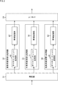
- FIG. 1 is a diagram showing a configuration example of an embodiment of a signal processing device to which the present technology is applied.
- the signal processing device 11 shown in FIG. 1 includes, for example, a smart phone, a portable player, a sound amplifier, a personal computer, a tablet, or the like.
- the signal processing device 11 includes a decoding unit 21, an audio selection unit 22, a high-quality sound processing unit 23, a renderer 24, and a reproduction signal generation unit 25.
- the decoding unit 21 is supplied with, for example, a plurality of audio signals and encoded data obtained by encoding the metadata of those audio signals.
- the coded data is a bit stream of a predetermined coded format such as MPEG-H.
- the decoding unit 21 performs decoding processing on the supplied encoded data, and supplies each audio signal obtained as a result and the metadata of those audio signals to the audio selection unit 22.
- the audio selection unit 22 selects, for each of the plurality of audio signals supplied from the decoding unit 21, high-quality sound processing to be performed on the audio signal based on the metadata supplied from the decoding unit 21, and the selection result.
- the audio signal is supplied to the high-quality sound processing unit 23 according to the above.
- the audio selection unit 22 receives a plurality of audio signals from the decoding unit 21 and selects an audio signal to be subjected to high-quality sound processing such as high-load high-quality sound processing based on the metadata.
- the audio selection unit 22 has a selection unit 31-1 to a selection unit 31-m, and each of the selection units 31-1 to the selection unit 31-m has one audio signal and its audio signal. Metadata is supplied.
- the coded data includes n audio signals of each object and (m-n) audio signals of each channel as audio signals to be targeted for high sound quality. Then, the audio signal of the object and its metadata are supplied to the selection unit 31-1 to the selection unit 31-n, and the audio signal of the channel and its metadata are supplied to the selection unit 31- (n + 1) to the selection unit 31-m. Metadata is supplied.
- the selection unit 31-1 to the selection unit 31-m perform high-quality sound processing on the audio signal supplied from the decoding unit 21 based on the metadata supplied from the decoding unit 21, that is, the output destination of the audio signal. Block is selected, and an audio signal is supplied to the block of the high-quality sound processing unit 23 according to the selection result.
- the selection unit 31-1 to the selection unit 31-n supply the metadata of the audio signal of the object supplied from the decoding unit 21 to the renderer 24 via the high-quality sound processing unit 23.
- the selection unit 31 is also simply referred to as the selection unit 31.
- the high-quality sound processing unit 23 performs any of three types of predetermined high-quality sound processing on each audio signal supplied from the audio selection unit 22, and obtains the audio signal obtained as a result. Output as a high-quality sound signal.
- the three types of high-quality sound processing referred to here are the high-load high-quality sound processing, the medium-load high-quality sound processing, and the low-load high-quality sound processing described above.
- the high-quality sound processing unit 23 includes a high-load high-quality sound processing unit 32-1 to a high-load high-quality sound processing unit 32-m, and a medium-load high-quality sound processing unit 33-1 to a medium-load high-quality sound processing unit 33-. It has a low-load high-quality sound processing unit 34-1 to a low-load high-quality sound processing unit 34-m.
- the high-load and high-quality sound processing unit 32-1 to the high-load and high-quality sound processing unit 32-m refer to the supplied audio signal.
- the high-load, high-quality sound processing is performed to generate a high-quality sound signal.
- the high-load, high-quality sound processing unit 32-1 to the high-load, high-quality sound processing unit 32-n supplies the high-quality sound signal of each object obtained by the high-load, high-quality sound processing to the renderer 24.
- the high-load high-quality sound processing unit 32- (n + 1) to the high-load high-quality sound processing unit 32-m generate a reproduction signal of the high-quality sound signal of each channel obtained by the high-load high-quality sound processing. It is supplied to the unit 25.
- the high-load high-quality sound processing unit 32 when it is not necessary to particularly distinguish between the high-load high-quality sound processing unit 32-1 and the high-load high-quality sound processing unit 32-m, they are also simply referred to as the high-load high-quality sound processing unit 32.
- the medium-load high-quality sound processing unit 33-1 to the medium-load high-quality sound processing unit 33-m respond to the supplied audio signal.
- the medium load high-quality sound processing is performed to generate a high-quality sound signal.
- the medium-load high-quality sound processing unit 33-1 to the medium-load high-quality sound processing unit 33-n supply the high-quality sound signal of each object obtained by the medium-load high-quality sound processing to the renderer 24.
- the medium-load high-quality sound processing unit 33- (n + 1) to the medium-load high-quality sound processing unit 33-m generate a reproduction signal of the high-quality sound signal of each channel obtained by the medium-load high-quality sound processing. It is supplied to the unit 25.
- the medium-load high-quality sound processing unit 33 is also simply referred to as the medium-load high-quality sound processing unit 33.
- the low-load and high-quality sound processing unit 34-1 to the low-load and high-quality sound processing unit 34-m refer to the supplied audio signal.
- the low-load, high-quality sound processing is performed to generate a high-quality sound signal.
- the low-load and high-quality sound processing unit 34-1 to the low-load and high-quality sound processing unit 34-n supply the high-quality sound signal of each object obtained by the low-load and high-quality sound processing to the renderer 24.
- the low-load and high-quality sound processing unit 34- (n + 1) to the low-load and high-quality sound processing unit 34-m generate a reproduction signal of the high-quality sound signal of each channel obtained by the low-load and high-quality sound processing. It is supplied to the unit 25.
- the low-load and high-quality sound processing unit 34-1 when it is not necessary to distinguish between the low-load and high-quality sound processing unit 34-1 to the low-load and high-quality sound processing unit 34-m, they are also simply referred to as the low-load and high-quality sound processing unit 34.
- the renderer 24 was supplied from the high-load high-quality sound processing unit 32, the medium-load high-quality sound processing unit 33, and the low-load high-quality sound processing unit 34 based on the metadata supplied from the high-quality sound processing unit 23.
- the high-quality sound signal of each object is rendered according to the playback device such as the speaker in the subsequent stage.
- VBAP Vector Based Amplitude Panning
- an object reproduction signal is obtained in which the sound of each object is localized at the position indicated by the position information included in the metadata of those objects. Be done.
- This object reproduction signal is a multi-channel audio signal composed of (m-n) audio signals of each channel.
- the renderer 24 supplies the object reproduction signal obtained by the rendering process to the reproduction signal generation unit 25.
- the reproduction signal generation unit 25 is the object reproduction signal supplied from the renderer 24, and each channel supplied from the high-load high-quality sound processing unit 32, the medium-load high-quality sound processing unit 33, and the low-load high-quality sound processing unit 34. Performs a synthesis process that synthesizes the high-quality sound signal of.
- the object reproduction signal of the same channel and the high-quality sound signal are added (synthesized), and the reproduction signal of the (m-n) channel is generated.
- this reproduction signal is reproduced by (m-n) speakers, the sound of each channel and the sound of each object, that is, the sound of the content is reproduced.
- the reproduction signal generation unit 25 outputs the reproduction signal obtained by the synthesis processing to the subsequent stage.
- the high-load high-quality sound processing unit 32, the medium-load high-quality sound processing unit 33, and the low-load high-quality sound processing unit 34 are configured as shown in FIG.
- FIG. 2 shows an example in which the renderer 24 is provided after the high-load high-quality sound processing unit 32 to the low-load high-quality sound processing unit 34.
- the high-load, high-quality sound processing unit 32 has a dynamic range expansion unit 61 and a band expansion unit 62.
- the dynamic range expansion unit 61 performs dynamic range expansion processing based on the machine-learned DNN on the audio signal supplied from the selection unit 31, and supplies the audio signal obtained as a result to the band expansion unit 62. ..
- the band expansion unit 62 performs band expansion processing based on the machine-learned DNN on the audio signal supplied from the dynamic range expansion unit 61, and supplies the high-quality sound signal obtained as a result to the renderer 24. ..
- the medium-load high-quality sound processing unit 33 has a dynamic range expansion unit 71 and a band expansion unit 72.
- the dynamic range expansion unit 71 performs dynamic range expansion processing by a multi-stage all-pass filter on the audio signal supplied from the selection unit 31, and supplies the audio signal obtained as a result to the band expansion unit 72.
- the band expansion unit 72 performs band expansion processing using linear prediction on the audio signal supplied from the dynamic range expansion unit 71, and supplies the high-quality sound signal obtained as a result to the renderer 24.
- the low load and high sound quality processing unit 34 has a dynamic range expansion unit 81 and a band expansion unit 82.
- the dynamic range expansion unit 81 performs the same dynamic range expansion processing as in the dynamic range expansion unit 71 on the audio signal supplied from the selection unit 31, and transmits the audio signal obtained as a result to the band expansion unit 82. Supply.
- the band expansion unit 82 performs band expansion processing using the coefficient specified on the coding side on the audio signal supplied from the dynamic range expansion unit 81, and renders the resulting high-quality sound signal into the renderer 24. Supply to.
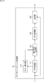
- FIG. 3 is a diagram showing a more detailed configuration example of the dynamic range expansion unit 61.
- the dynamic range expansion unit 61 shown in FIG. 3 includes an FFT (Fast Fourier Transform) processing unit 111, a gain calculation unit 112, a difference signal generation unit 113, an IFFT (Inverse Fast Fourier Transform) processing unit 114, and a synthesis unit 115. ing.
- FFT Fast Fourier Transform
- gain calculation unit 112 a gain calculation unit 112
- difference signal generation unit 113 a difference signal generation unit 113
- an IFFT Inverse Fast Fourier Transform
- a difference signal which is a difference between the audio signal obtained by decoding by the decoding unit 21 and the original sound signal before encoding of the audio signal, is predicted by a prediction calculation using DNN, and the difference signal is predicted.
- the difference signal and the audio signal are combined. By doing so, it is possible to obtain a high-quality audio signal closer to the original sound signal.
- the FFT processing unit 111 performs FFT on the audio signal supplied from the selection unit 31, and supplies the signal obtained as a result to the gain calculation unit 112 and the difference signal generation unit 113.
- the gain calculation unit 112 is composed of a DNN obtained in advance by machine learning. That is, the gain calculation unit 112 holds the prediction coefficient used for the calculation in DNN, which is obtained in advance by machine learning, and functions as a predictor for predicting the envelope of the frequency characteristic of the difference signal.
- the gain calculation unit 112 calculates the gain value as a parameter for generating the difference signal corresponding to the audio signal based on the holding prediction coefficient and the signal supplied from the FFT processing unit 111, and calculates the difference signal. It is supplied to the generation unit 113. That is, the gain of the frequency envelope of the difference signal is calculated as a parameter for generating the difference signal.
- the difference signal generation unit 113 generates a difference signal based on the signal supplied from the FFT processing unit 111 and the gain value supplied from the gain calculation unit 112, and supplies the difference signal to the IFFT processing unit 114.
- the IFFT processing unit 114 performs IFFT on the difference signal supplied from the difference signal generation unit 113, and supplies the difference signal in the time domain obtained as a result to the synthesis unit 115.
- the synthesis unit 115 synthesizes the audio signal supplied from the selection unit 31 and the difference signal supplied from the IFFT processing unit 114, and supplies the audio signal obtained as a result to the band expansion unit 62.
- band expansion unit 62 shown in FIG. 2 is configured as shown in FIG. 4, for example.
- the band expansion unit 62 shown in FIG. 4 includes a polyphase configuration low-pass filter 141, a delay circuit 142, a low-pass extraction band-pass filter 143, a feature amount calculation circuit 144, a high-frequency subband power estimation circuit 145, and a band-pass filter calculation. It has a circuit 146, an addition unit 147, a high-pass filter 148, a flattening circuit 149, a downsampling unit 150, a polyphase configuration level adjustment filter 151, and an addition unit 152.
- the polyphase configuration low-pass filter 141 filters the audio signal supplied from the synthesis section 115 of the dynamic range expansion section 61 by the polyphase configuration low-pass filter, and the low-pass signal obtained as a result. Is supplied to the delay circuit 142.
- the signal is upsampled and the low-pass component is extracted by filtering by the polyphase-configured low-pass filter, and a low-pass signal is obtained.
- the delay circuit 142 delays the low-frequency signal supplied from the polyphase configuration low-pass filter 141 by a certain delay time and supplies it to the addition unit 152.
- the low frequency extraction band pass filter 143 is composed of a band pass filter 161-1 to a band pass filter 161-K having different pass bands.
- the band pass filter 161-k (however, 1 ⁇ k ⁇ K) passes a sub-band signal which is a predetermined pass band on the low frequency side of the audio signal supplied from the synthesis unit 115, and is obtained as a result.
- the signal of the predetermined band is supplied to the feature amount calculation circuit 144 and the flattening circuit 149 as a low frequency subband signal. Therefore, in the low frequency extraction band pass filter 143, low frequency subband signals of K subbands included in the low frequency band can be obtained.
- band-passing filter 161-1 when it is not necessary to distinguish between the band-passing filter 161-1 and the band-passing filter 161-K, it is also simply referred to as the band-passing filter 161.
- the feature amount calculation circuit 144 calculates the feature amount based on each of the plurality of low-frequency subband signals supplied from the bandpass filter 161 or the audio signal supplied from the synthesis unit 115, and is a high-frequency subband power estimation circuit. Supply to 145.
- the high frequency subband power estimation circuit 145 is composed of a DNN obtained in advance by machine learning. That is, the high frequency subband power estimation circuit 145 holds the prediction coefficient used for the calculation in DNN, which is obtained in advance by machine learning.
- the high-frequency subband power estimation circuit 145 estimates the high-frequency subband power, which is the power of the high-frequency subband signal, based on the holding prediction coefficient and the feature amount supplied from the feature amount calculation circuit 144. The value is calculated for each high-frequency subband and supplied to the bandpass filter calculation circuit 146.
- the estimated value of the high frequency subband power will also be referred to as a pseudo high frequency subband power.
- the bandpass filter calculation circuit 146 sets each band of the high frequency subband as the passband based on the pseudo high frequency subband power of each of the plurality of high frequency subbands supplied from the high frequency subband power estimation circuit 145.
- the band pass filter coefficient of the band pass filter to be used is calculated and supplied to the addition unit 147.
- the addition unit 147 adds the band pass filter coefficients supplied from the band pass filter calculation circuit 146 to form one filter coefficient, and supplies the filter coefficient to the high frequency pass filter 148.
- the high-pass filter 148 removes low-pass components from the filter coefficient by filtering the filter coefficient supplied from the addition unit 147 using the high-pass filter, and the resulting filter coefficient has a polyphase configuration. It is supplied to the level adjustment filter 151. That is, the high frequency pass filter 148 passes only the high frequency component of the filter coefficient.
- the flattening circuit 149 flattens and adds the low-frequency subband signals of each of the plurality of low-frequency subbands supplied from the bandpass filter 161 to generate a flattening signal, and supplies the flattening signal to the downsampling unit 150.
- the downsampling unit 150 downsamples the flattening signal supplied from the flattening circuit 149, and supplies the downsampled flattening signal to the polyphase configuration level adjustment filter 151.
- the polyphase configuration level adjustment filter 151 generates a high frequency signal by filtering the flattening signal supplied from the downsampling unit 150 using the filter coefficient supplied from the high frequency pass filter 148. It is supplied to the addition unit 152.
- the adder 152 adds the low-frequency signal supplied from the delay circuit 142 and the high-frequency signal supplied from the polyphase configuration level adjustment filter 151 to obtain a high-quality sound signal, and uses the renderer 24 or the reproduction signal generation unit 25. Supply to.
- the high-frequency signal obtained by the polyphase configuration level adjustment filter 151 is a high-frequency component signal that is not included in the original audio signal, that is, a high-frequency component that is missing when the audio signal is encoded, for example. It is a signal. Therefore, by synthesizing such a high-frequency signal into a low-frequency signal that is a low-frequency component of the original audio signal, a signal containing a component in a wider frequency band, that is, a higher-quality sound is improved. You can get a signal.
- the dynamic range expansion unit 71 of the medium-load high-quality sound processing unit 33 shown in FIG. 2 is configured as shown in FIG. 5, for example.
- the dynamic range expansion unit 71 shown in FIG. 5 includes an all-pass filter 191-1 to an all-pass filter 191-3, a gain adjustment unit 192, and an addition unit 193.
- an all-pass filter 191-1 to 191-3 are cascade-connected.
- the all-pass filter 191-1 filters the audio signal supplied from the selection unit 31, and supplies the audio signal obtained as a result to the subsequent all-pass filter 191-2.
- the all-pass filter 191-2 filters the audio signal supplied from the all-pass filter 191-1, and supplies the audio signal obtained as a result to the subsequent all-pass filter 193-1.
- the all-pass filter 191-3 filters the audio signal supplied from the all-pass filter 191-2, and supplies the audio signal obtained as a result to the gain adjustment unit 192.
- all-pass filter 191-1 when it is not necessary to distinguish the all-pass filter 191-1 to the all-pass filter 191-1-3, it is also simply referred to as the all-pass filter 191.
- the gain adjustment unit 192 adjusts the gain of the audio signal supplied from the all-pass filter 191-3, and supplies the audio signal after the gain adjustment to the addition unit 193.
- the addition unit 193 adds the audio signal supplied from the gain adjustment unit 192 and the audio signal supplied from the selection unit 31 to generate an audio signal with improved sound quality, that is, an extended dynamic range. Then, it is supplied to the band expansion unit 72.
- the processing performed by the dynamic range expansion unit 71 is filtering and gain adjustment, it is realized with a smaller (lower) processing load than the arithmetic processing performed by the DNN as performed by the dynamic range expansion unit 61 shown in FIG. be able to.
- band expansion unit 72 shown in FIG. 2 is configured as shown in FIG. 6, for example.
- the band expansion unit 72 shown in FIG. 6 includes a polyphase configuration low-pass filter 221, a delay circuit 222, a low-pass extraction band-pass filter 223, a feature amount calculation circuit 224, a high-frequency subband power estimation circuit 225, and a band-pass filter calculation. It has a circuit 226, an addition unit 227, a high frequency pass filter 228, a flattening circuit 229, a downsampling unit 230, a polyphase configuration level adjustment filter 231 and an addition unit 232.
- the low frequency extraction band pass filter 223 has a band pass filter 241-1 to a band pass filter 241-K.
- the polyphase configuration low-pass filter 221 to the feature amount calculation circuit 224 and the band pass filter calculation circuit 226 to the addition unit 232 are the polyphase configuration low-pass filter 141 to the feature of the band expansion unit 62 shown in FIG. Since it has the same configuration as the quantity calculation circuit 144 and the bandpass filter calculation circuit 146 to the addition unit 152 and performs the same operation, the description thereof will be omitted.
- band-passing filter 241-1 to the band-passing filter 241-K also have the same configuration as the band-passing filter 161-1 to the band-passing filter 161-K of the band expansion unit 62 shown in FIG. 4, and perform the same operation. Since it is performed, the description thereof will be omitted.
- band-passing filter 241-1 when it is not necessary to distinguish between the band-passing filter 241-1 and the band-passing filter 241-K, it is also simply referred to as the band-passing filter 241.
- the band expansion unit 72 shown in FIG. 6 differs from the band expansion unit 62 shown in FIG. 4 only in the operation in the high frequency subband power estimation circuit 225, and has the same configuration and operation as the band expansion unit 62 in other respects. It has become.
- the high frequency subband power estimation circuit 225 holds a coefficient obtained by statistical learning in advance, and is a pseudo high frequency sub based on the retained coefficient and the feature amount supplied from the feature amount calculation circuit 224.
- the band power is calculated and supplied to the band pass filter calculation circuit 226.
- the high frequency component more specifically, the pseudo high frequency subband power is calculated by linear prediction using the retained coefficient.
- the linear prediction in the high frequency subband power estimation circuit 225 can be realized with a smaller processing load as compared with the prediction by the DNN calculation in the high frequency subband power estimation circuit 145.
- the dynamic range expansion unit 81 of the low load and high sound quality processing unit 34 shown in FIG. 2 has the same configuration as the dynamic range expansion unit 71 shown in FIG. 5, for example.
- the low-load, high-quality sound processing unit 34 may not be provided with the dynamic range expansion unit 81.
- band expansion unit 82 of the low load and high sound quality processing unit 34 shown in FIG. 2 is configured as shown in FIG. 7, for example.
- the band expansion unit 82 shown in FIG. 7 includes a subband division circuit 271, a feature amount calculation circuit 272, a high frequency decoding circuit 273, a decoding high frequency subband power calculation circuit 274, a decoding high frequency signal generation circuit 275, and a synthesis circuit 276. have.
- the coded data supplied to the decoding unit 21 includes high-frequency coded data, and the high-frequency coded data is included in the coded data. It is supplied to the high frequency decoding circuit 273.
- the high-frequency coded data is data obtained by encoding an index for obtaining a high-frequency subband power estimation coefficient, which will be described later.
- the subband division circuit 271 equally divides the audio signal supplied from the dynamic range expansion unit 81 into a plurality of low-frequency subband signals having a predetermined bandwidth, and features the feature amount calculation circuit 272 and the decoded high-frequency signal generation circuit. Supply to 275.
- the feature amount calculation circuit 272 calculates the feature amount based on the low frequency subband signal supplied from the subband division circuit 271 and supplies it to the decoding high frequency subband power calculation circuit 274.
- the high-frequency decoding circuit 273 decodes the supplied high-frequency coded data, and supplies the high-frequency subband power estimation coefficient corresponding to the index obtained as a result to the decoded high-frequency subband power calculation circuit 274.
- the high frequency subband power estimation coefficient is recorded for each of the plurality of indexes in association with those indexes.
- an index indicating the high frequency subband power estimation coefficient most suitable for the band expansion processing in the band expansion unit 82 is selected, and the selected index is encoded. Then, the high-frequency coded data obtained by the coding is stored in the bit stream and supplied to the signal processing device 11.
- the high-frequency decoding circuit 273 selects the one indicated by the index obtained by decoding the high-frequency coded data from the plurality of high-frequency subband power estimation coefficients recorded in advance, and decodes the high-frequency band. It is supplied to the subband power calculation circuit 274.
- the decoding high-frequency subband power calculation circuit 274 is based on the feature amount supplied from the feature amount calculation circuit 272 and the high-frequency subband power estimation coefficient supplied from the high-frequency decoding circuit 273, and is based on the high-frequency subband power. Is calculated and supplied to the decoding high frequency signal generation circuit 275.
- the decoded high frequency signal generation circuit 275 is a high frequency signal based on the low frequency subband signal supplied from the subband dividing circuit 271 and the high frequency subband power supplied from the decoded high frequency subband power calculation circuit 274. Is generated and supplied to the synthesis circuit 276.
- the synthesis circuit 276 synthesizes the audio signal supplied from the dynamic range expansion unit 81 and the high-frequency signal supplied from the decoding high-frequency signal generation circuit 275, and combines the resulting high-quality sound signal with the renderer 24 or It is supplied to the reproduction signal generation unit 25.
- the high-frequency signal obtained by the decoded high-frequency signal generation circuit 275 is a high-frequency component signal that is not included in the original audio signal. Therefore, by synthesizing such a high-frequency signal with the original audio signal, it is possible to obtain a high-quality sound signal containing a wider frequency band component.
- the band expansion unit 72 shown in FIG. 6 is used. It can be realized with a smaller processing load than in the case of.
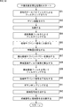
- reproduction signal generation process by the signal processing device 11 will be described below with reference to the flowchart of FIG.
- This reproduction signal generation process is started when the decoding unit 21 decodes the supplied coded data and supplies the audio signal and metadata obtained by the decoding to the selection unit 31.
- step S11 the selection unit 31 selects a high-quality sound process for the audio signal supplied from the decoding unit 21 based on the metadata supplied from the decoding unit 21.
- the selection unit 31 performs high-load high-quality sound processing, medium-load high-quality sound processing, and low-load high-quality sound processing based on the priority information and type information included in the supplied metadata. Select one of these processes as the process for improving sound quality.
- step S11 when the priority indicated by the priority information is equal to or less than a predetermined value, or when the type indicated by the type information is a specific type such as a center channel or vocal, a high load is applied. High-quality sound processing is selected.
- At least one of the priority information and the type information is used for selecting the high-quality sound processing, but the high-quality sound processing is selected by using other information indicating the processing capacity of the signal processing device 11. It may be done.
- the high-load high-quality sound is produced so that the number of audio signals for which the high-load high-quality sound processing is selected increases.
- the value of the priority for which the conversion process is selected is changed.
- step S12 the selection unit 31 determines whether or not to perform high-load, high-quality sound processing.
- step S11 when the high-load high-quality sound processing is selected as a result of the selection in step S11, it is determined that the high-load high-quality sound processing is performed in step S12.
- step S12 When it is determined in step S12 that the high-load high-quality sound processing is performed, the selection unit 31 supplies the audio signal supplied from the decoding unit 21 to the high-load high-quality sound processing unit 32, and then the processing is performed in step S13. Proceed to.
- step S13 the high-load, high-quality sound processing unit 32 performs high-load, high-quality sound processing on the audio signal supplied from the selection unit 31, and outputs the high-quality sound signal obtained as a result.
- the details of the high-load, high-quality sound processing will be described later.
- the high-load high-quality sound processing unit 32 supplies the obtained high-quality sound signal to the renderer 24.
- the selection unit 31 supplies the position information included in the metadata supplied from the decoding unit 21 to the renderer 24 via the high-quality sound processing unit 23.
- the high-load high-quality sound processing unit 32 supplies the obtained high-quality sound signal to the reproduction signal generation unit 25.
- step S17 When the high-load high-quality sound processing is performed and the high-quality sound signal is generated, the processing proceeds to step S17.
- step S12 If it is determined in step S12 that the high-load high-quality sound processing is not performed, the selection unit 31 determines in step S14 whether or not to perform the medium-load high-quality sound processing.
- step S11 when the medium-load high-quality sound processing is selected as a result of the selection in step S11, it is determined that the medium-load high-quality sound processing is performed in step S14.
- step S14 When it is determined in step S14 that the medium-load high-quality sound processing is performed, the selection unit 31 supplies the audio signal supplied from the decoding unit 21 to the medium-load high-quality sound processing unit 33, and then the processing is performed in step S15. Proceed to.
- step S15 the medium-load high-quality sound processing unit 33 performs medium-load high-quality sound processing on the audio signal supplied from the selection unit 31, and outputs the high-quality sound signal obtained as a result.
- the details of the medium-load and high-quality sound processing will be described later.
- the medium-load high-quality sound processing unit 33 supplies the obtained high-quality sound signal to the renderer 24.
- the selection unit 31 supplies the position information included in the metadata supplied from the decoding unit 21 to the renderer 24 via the high-quality sound processing unit 23.
- the medium-load high-quality sound processing unit 33 supplies the obtained high-quality sound signal to the reproduction signal generation unit 25.
- step S17 When the medium-load high-quality sound processing is performed and the high-quality sound signal is generated, the processing proceeds to step S17.
- step S14 when it is determined in step S14 that the medium load high sound quality processing is not performed, that is, when the low load high sound quality processing is performed, the processing proceeds to step S16.
- the selection unit 31 supplies the audio signal supplied from the decoding unit 21 to the low-load, high-quality sound processing unit 34.
- step S16 the low-load, high-quality sound processing unit 34 performs low-load, high-quality sound processing on the audio signal supplied from the selection unit 31, and outputs the high-quality sound signal obtained as a result.
- the details of the low-load, high-quality sound processing will be described later.
- the low-load high-quality sound processing unit 34 supplies the obtained high-quality sound signal to the renderer 24.
- the selection unit 31 supplies the position information included in the metadata supplied from the decoding unit 21 to the renderer 24 via the high-quality sound processing unit 23.
- the low-load high-quality sound processing unit 34 supplies the obtained high-quality sound signal to the reproduction signal generation unit 25.
- step S17 When the low-load high-quality sound processing is performed and the high-quality sound signal is generated, the processing proceeds to step S17.
- step S13 When the processing of step S13, step S15, or step S16 is performed, the processing of step S17 is performed thereafter.
- step S17 the audio selection unit 22 determines whether or not all the audio signals supplied from the decoding unit 21 have been processed.
- step S17 the selection unit 31-1 to the selection unit 31-m select the high-quality sound processing for the supplied audio signal, and the high-quality sound processing unit 23 improves the sound quality according to the selection result.
- processing it is determined that all audio signals have been processed. In this case, a high-quality sound signal corresponding to all audio signals is generated.
- step S17 If it is determined in step S17 that all the audio signals have not been processed yet, the processing returns to step S11, and the above-mentioned processing is repeated.
- the processing of steps S11 to S16 described above is performed on the audio signal supplied to the selection unit 31-n. .. More specifically, in the audio selection unit 22, the processing of steps S11 to S16 is performed in parallel by each selection unit 31.
- step S17 if it is determined in step S17 that all the audio signals have been processed, the processing proceeds to step S18.
- step S18 the renderer 24 has a total of n high-quality sound supplied from the high-load high-quality sound processing unit 32 of the high-quality sound processing unit 23, the medium-load high-quality sound processing unit 33, and the low-load high-quality sound processing unit 34. Rendering processing is performed on the sound quality signal.
- the renderer 24 generates an object reproduction signal by performing VBAP based on the position information of each object supplied from the high-quality sound processing unit 23 and the high-quality sound signal, and supplies the object reproduction signal to the reproduction signal generation unit 25.
- step S19 the reproduction signal generation unit 25 is supplied from the object reproduction signal supplied from the renderer 24, the high-load high-quality sound processing unit 32, the medium-load high-quality sound processing unit 33, and the low-load high-quality sound processing unit 34.
- a playback signal is generated by synthesizing the high-quality sound signal of each channel.
- the reproduction signal generation unit 25 outputs the obtained reproduction signal to the subsequent stage, and then the reproduction signal generation process ends.
- the signal processing device 11 performs high-quality sound for each audio signal from among a plurality of high-quality sound processing having different processing loads based on the priority information and type information included in the metadata.
- the sound quality enhancement process is selected, and the sound quality enhancement process is performed according to the selection result. By doing so, the processing load can be reduced as a whole, and a reproduced signal having sufficiently high sound quality can be obtained even with a small processing load, that is, a small amount of processing.
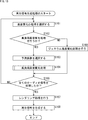
- step S41 the FFT processing unit 111 performs FFT on the audio signal supplied from the selection unit 31, and supplies the signal obtained as a result to the gain calculation unit 112 and the difference signal generation unit 113.
- step S42 the gain calculation unit 112 calculates a gain value for generating a difference signal based on the holding prediction coefficient and the signal supplied from the FFT processing unit 111, and causes the difference signal generation unit 113 to calculate a gain value. Supply.
- step S42 the DNN is calculated based on the prediction coefficient and the signal supplied from the FFT processing unit 111, and the gain value of the frequency envelope of the difference signal is calculated.
- step S43 the difference signal generation unit 113 generates a difference signal based on the signal supplied from the FFT processing unit 111 and the gain value supplied from the gain calculation unit 112, and supplies the difference signal to the IFFT processing unit 114.
- a difference signal is generated by adjusting the gain of the signal supplied from the FFT processing unit 111 based on the gain value.
- step S44 the IFFT processing unit 114 performs IFFT on the difference signal supplied from the difference signal generation unit 113, and supplies the difference signal obtained as a result to the synthesis unit 115.
- step S45 the synthesis unit 115 synthesizes the audio signal supplied from the selection unit 31 and the difference signal supplied from the IFFT processing unit 114, and the audio signal obtained as a result is combined with the polyphase configuration of the band expansion unit 62. It is supplied to the low-pass filter 141, the feature amount calculation circuit 144, and the band-pass filter 161.
- step S46 the polyphase configuration low-pass filter 141 filters the audio signal supplied from the synthesis unit 115 by the polyphase configuration low-pass filter, and delays the low-pass signal obtained as a result. Supply to 142.
- the delay circuit 142 delays the low-frequency signal supplied from the polyphase-configured low-pass filter 141 by a certain delay time, and then supplies the low-pass signal to the adder 152.
- each band-passing filter 161 divides the audio signal into a plurality of low-frequency subband signals by passing the low-frequency subband signal of the audio signal supplied from the synthesis unit 115, and the feature amount. It is supplied to the calculation circuit 144 and the flattening circuit 149.
- step S48 the feature amount calculation circuit 144 calculates the feature amount based on at least one of the plurality of low-frequency subband signals supplied from the bandpass filter 161 and the audio signal supplied from the synthesis unit 115. , Supply to the high frequency subband power estimation circuit 145.
- the high-frequency subband power estimation circuit 145 has a pseudo-high-frequency subband for each high-frequency subband based on the prediction coefficient held in advance and the feature amount supplied from the feature amount calculation circuit 144. The power is calculated and supplied to the bandpass filter calculation circuit 146.
- step S50 the bandpass filter calculation circuit 146 calculates the bandpass filter coefficient based on the pseudo high passband power of each of the plurality of high frequency subbands supplied from the high frequency subband power estimation circuit 145, and adds the bandpass filter coefficient. Supply to 147.
- the addition unit 147 adds the band pass filter coefficients supplied from the band pass filter calculation circuit 146 to form one filter coefficient, and supplies the filter coefficient to the high frequency pass filter 148.
- step S51 the high frequency pass filter 148 filters the filter coefficient supplied from the addition unit 147 using the high frequency pass filter, and supplies the filter coefficient obtained as a result to the polyphase configuration level adjustment filter 151.
- step S52 the flattening circuit 149 flattens and adds the low-frequency subband signals of each of the plurality of low-frequency subbands supplied from the bandpass filter 161 to generate a flattening signal, and causes the downsampling unit 150 to generate a flattening signal. Supply.
- step S53 the downsampling unit 150 downsamples the flattening signal supplied from the flattening circuit 149, and supplies the downsampled flattening signal to the polyphase configuration level adjustment filter 151.
- step S54 the polyphase configuration level adjustment filter 151 filters the flattening signal supplied from the downsampling unit 150 by using the filter coefficient supplied from the high frequency pass filter 148 to obtain a high frequency signal. Generate and supply to the addition unit 152.
- step S55 the adder 152 generates and outputs a high-quality sound signal by adding the low-frequency signal supplied from the delay circuit 142 and the high-frequency signal supplied from the polyphase configuration level adjustment filter 151. ..
- the high-quality sound signal is generated in this way, the high-load high-quality sound processing is completed, and then the processing proceeds to step S17 in FIG.
- the high-load, high-quality sound processing unit 32 generates a high-quality sound-enhancing signal by combining the dynamic range expansion processing and the band expansion processing, which can obtain a higher-quality sound signal even with a high load. do. By doing so, it is possible to obtain a high-quality sound signal for an important audio signal such as a high priority.
- the medium-load high-quality sound processing unit 33 performs the medium-load high-quality sound processing corresponding to step S15 of FIG.
- step S81 the all-pass filter 191 filters the audio signal supplied from the selection unit 31 by a multi-stage all-pass filter, and supplies the audio signal obtained as a result to the gain adjustment unit 192.
- step S81 filtering is performed by the all-pass filter 191-1 to the all-pass filter 191-3.
- step S82 the gain adjusting unit 192 adjusts the gain of the audio signal supplied from the all-pass filter 191-3, and supplies the gain-adjusted audio signal to the adding unit 193.
- step S83 the addition unit 193 adds the audio signal supplied from the gain adjustment unit 192 and the audio signal supplied from the selection unit 31, and the audio signal obtained as a result is combined with the polyphase configuration of the band expansion unit 72. It is supplied to the low-pass filter 221, the feature amount calculation circuit 224, and the band-pass filter 241.
- step S83 After the processing of step S83 is performed, the processing of steps S84 to S86 is performed by the polyphase configuration low-pass filter 221 and the band-passing filter 241 and the feature amount calculation circuit 224. Since these processes are the same as the processes of steps S46 to S48 of FIG. 9, the description thereof will be omitted.
- step S87 the high frequency subband power estimation circuit 225 calculates the pseudo high frequency subband power by linear prediction based on the retained coefficient and the feature amount supplied from the feature amount calculation circuit 224, and passes through the band. It is supplied to the filter calculation circuit 226.
- step S87 When the processing of step S87 is performed, the processing of steps S88 to S93 is subsequently performed by the bandpass filter calculation circuit 226 to the addition unit 232, and the medium load high-quality sound processing is completed. Since these processes are the same as the processes of steps S50 to S55 of FIG. 9, the description thereof will be omitted.
- the processing proceeds to step S17 in FIG.
- the medium-load high-quality sound processing unit 33 combines the dynamic range expansion processing and the band expansion processing, which can obtain a reasonably high-quality sound signal with a medium load, to obtain an audio signal of an object or a channel. To improve the sound quality. By doing so, for an audio signal having a high priority to some extent, a signal having a reasonably high sound quality can be obtained with a medium load.
- steps S121 to S123 Since the processing of steps S121 to S123 is the same as the processing of steps S81 to S83 of FIG. 10, the description thereof will be omitted.
- step S123 When the processing of step S123 is performed, the audio signal obtained by the processing of step S123 is supplied from the dynamic range expansion unit 81 to the subband division circuit 271 and the synthesis circuit 276 of the band expansion unit 82, and the processing of step S124. Is done.
- step S124 the sub-band division circuit 271 divides the audio signal supplied from the dynamic range expansion unit 81 into a plurality of low-frequency sub-band signals, and supplies the audio signal to the feature amount calculation circuit 272 and the decoded high-frequency signal generation circuit 275.
- step S125 the feature amount calculation circuit 272 calculates the feature amount based on the low frequency subband signal supplied from the subband division circuit 271 and supplies it to the decoding high frequency subband power calculation circuit 274.
- step S126 the high-frequency decoding circuit 273 decodes the supplied high-frequency coded data and outputs the high-frequency subband power estimation coefficient corresponding to the index obtained as a result to the decoding high-frequency subband power calculation circuit 274. (Supply).
- step S127 the decoding high-frequency subband power calculation circuit 274 is based on the feature amount supplied from the feature amount calculation circuit 272 and the high-frequency subband power estimation coefficient supplied from the high-frequency decoding circuit 273.
- the band power is calculated and supplied to the decoding high frequency signal generation circuit 275.
- the high-frequency subband power is calculated by obtaining the sum of the features multiplied by the high-frequency subband power estimation coefficient.
- step S128 the decoding high frequency signal generation circuit 275 is based on the low frequency subband signal supplied from the subband division circuit 271 and the high frequency subband power supplied from the decoding high frequency subband power calculation circuit 274.
- a high frequency signal is generated and supplied to the synthesis circuit 276.
- frequency modulation and gain adjustment are performed on the low-frequency subband signal based on the low-frequency subband signal and the high-frequency subband power to generate a high-frequency signal.
- step S129 the synthesis circuit 276 synthesizes the audio signal supplied from the dynamic range expansion unit 81 and the high frequency signal supplied from the decoding high frequency signal generation circuit 275, and obtains a high sound quality signal obtained as a result. Output.
- the high-quality sound signal is generated in this way, the low-load high-quality sound processing is completed, and then the processing proceeds to step S17 in FIG.
- the low-load, high-quality sound processing unit 34 combines the dynamic range expansion processing and the band expansion processing, which can realize high-quality sound with a low load, to improve the sound quality of the audio signal of the object or channel. By doing so, it is possible to improve the sound quality with a low load and reduce the overall processing load for an audio signal that is not so important, such as a low priority.
- the high-load, high-quality sound processing unit 32 uses the prediction coefficient used for the DNN calculation obtained in advance by machine learning, and estimates (predicts) the gain of the frequency envelope and the pseudo-high frequency subband power. ).
- the prediction coefficient for each type it is possible to predict the gain of the frequency envelope and the pseudo-high frequency subband power more accurately and with less processing load by using the prediction coefficient according to the type of the audio signal.
- the prediction coefficient that is, the DNN
- the gain value and pseudo-high-frequency subband power can be predicted accurately with a smaller-scale DNN, and the processing load can be reduced. can.
- the same DNN that is, the same prediction coefficient may be used regardless of the type of audio signal.
- general stereo audio content of various sound sources which is also called a complete package, may be used for machine learning of prediction coefficients.
- the prediction coefficient commonly used for all types which is generated by machine learning using audio content including sounds of various sound sources such as a complete package, will also be referred to as a particularly general prediction coefficient.
- the metadata of each audio signal since the metadata of each audio signal includes type information indicating the type of the audio signal, it is possible to specify the type of the audio signal. Therefore, for example, as shown in FIG. 12, a prediction coefficient according to the type information may be selected to improve the sound quality.
- a prediction coefficient according to the type information may be selected to improve the sound quality.
- the signal processing device 11 shown in FIG. 12 includes a decoding unit 21, an audio selection unit 22, a high-quality sound processing unit 23, a renderer 24, and a reproduction signal generation unit 25.
- the audio selection unit 22 has a selection unit 31-1 to a selection unit 31-m.
- the high-quality sound processing unit 23 includes a general high-quality sound processing unit 302-1 to a general high-quality sound processing unit 302-m, a high-load high-quality sound processing unit 32-1 to a high-load high-quality sound processing unit 32- It has m and a coefficient selection unit 301-1 to a coefficient selection unit 301-m.
- the signal processing device 11 shown in FIG. 12 differs from the signal processing device 11 shown in FIG. 1 only in the configuration of the high-quality sound processing unit 23, and the other configurations are the same.
- the coefficient selection unit 301-1 to the coefficient selection unit 301-m hold in advance the prediction coefficients used for the calculation in DNN, which are machine-learned for each type of audio signal, and these coefficient selection units 301-1.
- metadata is supplied from the decoding unit 21.
- the prediction coefficient referred to here is the processing by the high-load, high-quality sound processing unit 32, more specifically, the processing by the gain calculation unit 112 of the dynamic range expansion unit 61, and the high-frequency subband power estimation circuit 145 of the band expansion unit 62. It is a prediction coefficient used in the processing of.
- the coefficient selection unit 301-1 to the coefficient selection unit 301-m are of the types indicated by the type information included in the metadata supplied from the decoding unit 21 from among the plurality of prediction coefficients for each type held in advance.
- a prediction coefficient is selected and supplied to the high-load high-quality sound processing unit 32-1 to the high-load high-quality sound processing unit 32-m. That is, for each audio signal, the prediction coefficient used for the high-load, high-quality sound processing performed on those audio signals is selected.
- the coefficient selection unit 301 is also simply referred to as the coefficient selection unit 301.
- the general high-quality sound processing unit 302-1 to the general high-quality sound processing unit 302-m basically have the same configuration as the high-load high-quality sound processing unit 32.
- the block configuration corresponding to the gain calculation unit 112 and the high-frequency subband power estimation circuit 145 that is, the DNN configuration has a high load. It is different from the high-quality sound processing unit 32, and the above-mentioned general prediction coefficient is held in those blocks.
- the general high-quality sound processing unit 302-1 to the general high-quality sound processing unit 302-m have a DNN configuration depending on, for example, whether the input audio signal belongs to an object or a channel. Etc. may be different.
- the general high-quality sound processing unit 302-1 to the general high-quality sound processing unit 302-m hold the audio signals in advance. High-quality sound processing is performed based on the general prediction coefficient, and the high-quality sound signal obtained as a result is supplied to the renderer 24 or the reproduction signal generation unit 25.
- the general high-quality sound processing unit 302-1 when it is not necessary to distinguish the general high-quality sound processing unit 302-1 to the general high-quality sound processing unit 302-m, it is also simply referred to as the general high-quality sound processing unit 302. Further, hereinafter, the high-quality sound processing performed by the general high-quality sound processing unit 302 will also be referred to as a general high-quality sound processing.
- each selection unit 31 uses the general high-quality sound processing unit 302 and the high-load high-quality sound as the audio signal supply destination based on the priority information and the type information included in the metadata.
- One of the chemical processing units 32 is selected.
- step S161 the selection unit 31 selects a high-quality sound process for the audio signal supplied from the decoding unit 21 based on the metadata supplied from the decoding unit 21.
- the selection unit 31 selects the high-load, high-quality sound processing when the type indicated by the type information included in the metadata is a type in which the prediction coefficient is held in advance in the coefficient selection unit 301.
- the type indicated by the type information is a type in which the prediction coefficient is not held in the coefficient selection unit 301, the general high-quality sound processing is selected.
- step S162 the selection unit 31 determines whether or not the high-load high-quality sound processing is selected in step S161, that is, whether or not the high-load high-quality sound processing is performed.
- step S162 When it is determined in step S162 that the high-load high-quality sound processing is performed, the selection unit 31 supplies the audio signal supplied from the decoding unit 21 to the high-load high-quality sound processing unit 32, and then the processing is performed in step S163. Proceed to.
- step S163 the coefficient selection unit 301 selects the type prediction coefficient indicated by the type information included in the metadata supplied from the decoding unit 21 from among the plurality of type prediction coefficients held in advance. It is supplied to the high-load, high-quality sound processing unit 32.
- the prediction coefficients used in each of the gain calculation unit 112 and the high frequency subband power estimation circuit 145 which are generated in advance by machine learning for each type, are selected, and the gain calculation unit 112 and the high frequency subband power are selected.
- a prediction coefficient is supplied to the estimation circuit 145.
- step S164 the process of step S164 is performed thereafter. That is, in step S164, the high-load, high-quality sound processing described with reference to FIG. 9 is performed.
- step S42 the gain calculation unit 112 calculates the gain value for generating the difference signal based on the prediction coefficient supplied from the coefficient selection unit 301 and the signal supplied from the FFT processing unit 111. Further, in step S49, the high frequency subband power estimation circuit 145 obtains a pseudo high frequency subband power based on the prediction coefficient supplied from the coefficient selection unit 301 and the feature amount supplied from the feature amount calculation circuit 144. calculate.
- step S162 when it is determined in step S162 that the high-load high-quality sound processing is not performed, that is, when it is determined that the general high-quality sound processing is performed, the selection unit 31 uses the audio signal supplied from the decoding unit 21. It is supplied to the general high-quality sound processing unit 302, and then the processing proceeds to step S165.
- step S165 the general high-quality sound processing unit 302 performs general high-quality sound processing on the audio signal supplied from the selection unit 31, and the high-quality sound signal obtained as a result is used by the renderer 24 or the reproduction signal generation unit 25. Supply to.
- the pre-held general prediction coefficient is used to calculate the gain value for generating the difference signal.
- the pseudo high frequency subband power is calculated by using the general prediction coefficient held in advance.
- step S164 or step S165 When the processing of step S164 or step S165 is performed as described above, the processing of steps S166 to S168 is performed thereafter to end the reproduction signal generation processing, but these processing are performed in steps S17 to S17 of FIG. Since it is the same as the process of S19, the description thereof will be omitted.
- the signal processing device 11 selectively performs general high-quality sound processing or high-load high-quality sound processing based on the priority information and type information included in the metadata to generate a reproduced signal. By doing so, it is possible to obtain a reproduced signal having sufficiently high sound quality even with a small processing load, that is, a small amount of processing.
- a small processing load that is, a small amount of processing.
- by preparing a prediction coefficient for each type of audio signal a high-quality sound reproduction signal can be obtained even with a small processing load.
- FIG. 12 has described an example in which high-load high-quality sound processing or general high-quality sound processing is selected as the high-quality sound processing.
- the present invention is not limited to this, and selection is made from any two or more of high-load high-quality sound processing, medium-load high-quality sound processing, low-load high-quality sound processing, and general high-quality sound processing. It may be.
- the signal processing device 11 when any one of high-load high-quality sound processing, medium-load high-quality sound processing, low-load high-quality sound processing, and general high-quality sound processing is selected as the high-quality sound processing, the signal processing device 11 , As shown in FIG. In FIG. 14, the parts corresponding to the cases in FIGS. 1 or 12 are designated by the same reference numerals, and the description thereof will be omitted as appropriate.
- the signal processing device 11 shown in FIG. 14 includes a decoding unit 21, an audio selection unit 22, a high-quality sound processing unit 23, a renderer 24, and a reproduction signal generation unit 25.
- the audio selection unit 22 has a selection unit 31-1 to a selection unit 31-m.
- the high-quality sound processing unit 23 includes general high-quality sound processing unit 302-1 to general high-quality sound processing unit 302-m, medium-load high-quality sound processing unit 33-1 to medium-load high-quality sound processing unit 33-. m, low-load high-quality sound processing unit 34-1 to low-load high-quality sound processing unit 34-m, high-load high-quality sound processing unit 32-1 to high-load high-quality sound processing unit 32-m, and coefficient selection unit. It has 301-1 to a coefficient selection unit 301-m.
- the signal processing device 11 shown in FIG. 14 differs from the signal processing device 11 shown in FIGS. 1 and 12 only in the configuration of the high-quality sound processing unit 23, and the other configurations are the same.
- the selection unit 31 selects high-quality sound processing performed on the audio signal supplied from the decoding unit 21 based on the metadata supplied from the decoding unit 21.
- the selection unit 31 selects high-load high-quality sound processing, medium-load high-quality sound processing, low-load high-quality sound processing, or general high-quality sound processing, and sets the audio signal to high load according to the selection result. It is supplied to the high-quality sound processing unit 32, the medium-load high-quality sound processing unit 33, the low-load high-quality sound processing unit 34, or the general high-quality sound processing unit 302.
- a metadata generation unit that generates metadata based on an audio signal may be provided.
- the type of the audio signal is specified based on the audio signal and the type information indicating the specific result is generated as metadata will be described.
- the signal processing device 11 is configured as shown in FIG. 15, for example.
- the parts corresponding to the case in FIG. 12 are designated by the same reference numerals, and the description thereof will be omitted as appropriate.
- the signal processing device 11 shown in FIG. 15 includes a decoding unit 21, an audio selection unit 22, a high-quality sound processing unit 23, a renderer 24, and a reproduction signal generation unit 25.
- the audio selection unit 22 has a selection unit 31-1 to a selection unit 31-m, and a metadata generation unit 341-1 to a metadata generation unit 341-m.
- the high-quality sound processing unit 23 includes a general high-quality sound processing unit 302-1 to a general high-quality sound processing unit 302-m, a high-load high-quality sound processing unit 32-1 to a high-load high-quality sound processing unit 32- It has m and a coefficient selection unit 301-1 to a coefficient selection unit 301-m.
- the signal processing device 11 shown in FIG. 15 differs from the signal processing device 11 shown in FIG. 12 only in the configuration of the audio selection unit 22, and the other configurations are the same.
- the metadata generation unit 341-1 to the metadata generation unit 341-m are, for example, a type classifier such as a DNN generated in advance by machine learning or the like, and hold in advance a type prediction coefficient for realizing the type classifier. doing. That is, a type classifier such as DNN can be obtained by learning the type prediction coefficient by machine learning or the like.
- the metadata generation unit 341-1 to the metadata generation unit 341-m perform calculations by the type classifier based on the type prediction coefficient held in advance and the audio signal supplied from the decoding unit 21. Identify (estimate) the type of audio signal. For example, in a type classifier, the type is specified based on the frequency characteristics of the audio signal and the like.
- the metadata generation unit 341-1 to the metadata generation unit 341-m generate type information indicating the specific result of the type, that is, metadata, and the selection unit 31-1 to the selection unit 31-m and the coefficient selection unit 301. It is supplied to -1 to the coefficient selection unit 301-m.
- the metadata generation unit 341 when it is not necessary to distinguish the metadata generation unit 341-1 to the metadata generation unit 341-m, it is also simply referred to as the metadata generation unit 341.
- the type classifier constituting the metadata generation unit 341 may output, for the input audio signal, which of the plurality of types of the audio signal is.
- a plurality of type classifiers for each type may be prepared to output whether or not the input audio signal is of a specific type. For example, when a type classifier is prepared for each type, an audio signal is input to the various type classifiers, and type information is generated based on the output of the various type classifiers.
- the general high-quality sound processing unit 302 and the high-load high-quality sound processing unit 32 are provided in the high-quality sound processing unit 23
- the medium-load high-quality sound processing unit 33 and the low-load high-quality sound processing unit 33 have been described.
- the chemical processing unit 34 may also be provided.
- step S201 the metadata generation unit 341 identifies the type of the audio signal based on the type prediction coefficient held in advance and the audio signal supplied from the decoding unit 21, and generates type information indicating the specific result. do.
- the metadata generation unit 341 supplies the generated type information to the selection unit 31 and the coefficient selection unit 301.
- step S201 is performed only when the metadata obtained by the decoding unit 21 does not include the type information.
- the explanation will be continued assuming that the metadata does not include the type information.
- step S202 the selection unit 31 sets the audio signal supplied from the decoding unit 21 based on the priority information included in the metadata supplied from the decoding unit 21 and the type information supplied from the metadata generation unit 341. Select the high-quality sound processing to be performed.
- the high-quality sound processing high-load high-quality sound processing or general high-quality sound processing is selected.
- step S204 the coefficient selection unit 301 selects the prediction coefficient based on the type information supplied from the metadata generation unit 341.
- the signal processing device 11 generates type information based on the audio signal, and selects high-quality sound processing based on the type information and priority information. By doing so, even if the metadata does not include the type information, the type information can be generated, and high-quality sound processing and prediction coefficient selection can be performed. As a result, a high-quality sound reproduction signal can be obtained even with a small processing load.
- the series of processes described above can be executed by hardware or software.
- the programs that make up the software are installed on the computer.
- the computer includes a computer embedded in dedicated hardware and, for example, a general-purpose personal computer capable of executing various functions by installing various programs.
- FIG. 17 is a block diagram showing a configuration example of computer hardware that executes the above-mentioned series of processes programmatically.
- the CPU Central Processing Unit
- the ROM ReadOnly Memory
- the RAM RandomAccessMemory
- An input / output interface 505 is further connected to the bus 504.
- An input unit 506, an output unit 507, a recording unit 508, a communication unit 509, and a drive 510 are connected to the input / output interface 505.
- the input unit 506 includes a keyboard, a mouse, a microphone, an image sensor, and the like.
- the output unit 507 includes a display, a speaker, and the like.
- the recording unit 508 includes a hard disk, a non-volatile memory, and the like.
- the communication unit 509 includes a network interface and the like.
- the drive 510 drives a removable recording medium 511 such as a magnetic disk, an optical disk, a magneto-optical disk, or a semiconductor memory.
- the CPU 501 loads the program recorded in the recording unit 508 into the RAM 503 via the input / output interface 505 and the bus 504 and executes the above-described series. Is processed.
- the program executed by the computer can be recorded and provided on a removable recording medium 511 as a package medium or the like, for example. Programs can also be provided via wired or wireless transmission media such as local area networks, the Internet, and digital satellite broadcasts.
- the program can be installed in the recording unit 508 via the input / output interface 505 by mounting the removable recording medium 511 in the drive 510. Further, the program can be received by the communication unit 509 and installed in the recording unit 508 via a wired or wireless transmission medium. In addition, the program can be installed in advance in the ROM 502 or the recording unit 508.
- the program executed by the computer may be a program that is processed in chronological order according to the order described in this specification, or may be a program that is processed in parallel or at a necessary timing such as when a call is made. It may be a program in which processing is performed.
- the embodiment of the present technology is not limited to the above-described embodiment, and various changes can be made without departing from the gist of the present technology.
- this technology can have a cloud computing configuration in which one function is shared by a plurality of devices via a network and processed jointly.
- each step described in the above flowchart can be executed by one device or shared by a plurality of devices.
- one step includes a plurality of processes
- the plurality of processes included in the one step can be executed by one device or shared by a plurality of devices.
- this technology can also have the following configurations.
- a selection unit that selects the audio signal that receives the supply of a plurality of audio signals and performs high-quality sound processing
- the selection unit selects the audio signal to be subjected to the high-quality sound processing based on the metadata of the audio signal.
- the metadata includes priority information indicating the priority of the audio signal.
- the metadata includes type information indicating the type of the audio signal.
- the signal processing device according to any one of (2) to (4), further comprising a metadata generation unit that generates the metadata based on the audio signal.
- the selection unit selects any one of (1) to (5) from among a plurality of high-quality sound processings that are different from each other for each audio signal.
- the signal processing device according to the section.
- the signal processing device wherein the high-quality sound processing is a dynamic range expansion processing or a band expansion processing.
- the high-quality sound processing is a dynamic range expansion processing or a band expansion processing based on a prediction coefficient obtained by machine learning and the audio signal.
- the prediction coefficient is held for each type of the audio signal, and the prediction coefficient used for the high-quality sound processing is selected from among the plurality of held prediction coefficients based on the type information indicating the type of the audio signal.
- the signal processing device according to (6), wherein the high-quality sound processing is a band expansion processing that generates high-frequency components by linear prediction based on the audio signal.
- the high-quality sound processing is a band expansion processing for adding white noise to the audio signal.
- the signal processing device Select the audio signal that receives the supply of multiple audio signals and performs high-quality sound processing, A signal processing method for performing the high-quality sound processing on the selected audio signal.
- the signal processing device Select the audio signal that receives the supply of multiple audio signals and performs high-quality sound processing, A program that causes a computer to execute a process including a step of performing the high-quality sound processing on the selected audio signal.
Landscapes
- Engineering & Computer Science (AREA)
- Computational Linguistics (AREA)
- Quality & Reliability (AREA)
- Signal Processing (AREA)
- Health & Medical Sciences (AREA)
- Audiology, Speech & Language Pathology (AREA)
- Human Computer Interaction (AREA)
- Physics & Mathematics (AREA)
- Acoustics & Sound (AREA)
- Multimedia (AREA)
- Tone Control, Compression And Expansion, Limiting Amplitude (AREA)
- Stereophonic System (AREA)
Abstract
本技術は、少ない処理量でも高音質な信号を得ることができるようにする信号処理装置および方法、並びにプログラムに関する。 信号処理装置は、複数のオーディオ信号の供給を受け、高音質化処理を施すオーディオ信号を選択する選択部と、選択部により選択されたオーディオ信号に対して、高音質化処理を行う高音質化処理部とを備える。本技術はポータブル端末に適用することができる。
Description
本技術は、信号処理装置および方法、並びにプログラムに関し、特に少ない処理量でも高音質な信号を得ることができるようにした信号処理装置および方法、並びにプログラムに関する。
従来、オーディオ信号に対する高音質化のための処理、すなわち音質改善のための処理として、帯域拡張処理やダイナミックレンジ拡張処理が知られている。
例えばそのような帯域拡張処理として、低域サブバンド信号に基づいて高域を通過帯域とする帯域通過フィルタのフィルタ係数を算出し、そのフィルタ係数を用いて低域サブバンド信号から得られる平坦化信号をフィルタリングすることで高域信号を生成する技術が提案されている(例えば、特許文献1参照)。
ところで、複数のオブジェクトごとのオーディオ信号を含むオブジェクトオーディオについて、全てのオブジェクトのオーディオ信号に対して同等に高音質化のための処理を行おうとすると、当然、オブジェクト数分の処理が必要となる。
したがって、例えばスマートホンやポータブルプレーヤ、サウンドアンプなどといった、現状のプラットフォームでは処理しきれなくなってしまうことがある。
例えば、比較的オブジェクト数の少ない12オブジェクトでも、それらの12個の全てのオブジェクトに対して高音質化の処理を行おうとすると、1 GCPS(cycles per second)乃至3 GCPSという膨大な処理量となってしまう。
本技術は、このような状況に鑑みてなされたものであり、少ない処理量でも高音質な信号を得ることができるようにするものである。
本技術の一側面の信号処理装置は、複数のオーディオ信号の供給を受け、高音質化処理を施す前記オーディオ信号を選択する選択部と、前記選択部により選択された前記オーディオ信号に対して、前記高音質化処理を行う高音質化処理部とを備える。
本技術の一側面の信号処理方法またはプログラムは、複数のオーディオ信号の供給を受け、高音質化処理を施す前記オーディオ信号を選択し、選択された前記オーディオ信号に対して、前記高音質化処理を行うステップを含む。
本技術の一側面においては、複数のオーディオ信号の供給を受け、高音質化処理を施す前記オーディオ信号が選択され、選択された前記オーディオ信号に対して、前記高音質化処理が行われる。
以下、図面を参照して、本技術を適用した実施の形態について説明する。
〈第1の実施の形態〉
〈本技術について〉
本技術は、オブジェクトオーディオに代表されるマルチチャンネル・オーディオの高音質化を行う場合に、メタデータ等を用いて、各オーディオ信号に対して行われる処理を差異化することで、少ない処理量でも高音質な信号を得ることができるようにするものである。
〈本技術について〉
本技術は、オブジェクトオーディオに代表されるマルチチャンネル・オーディオの高音質化を行う場合に、メタデータ等を用いて、各オーディオ信号に対して行われる処理を差異化することで、少ない処理量でも高音質な信号を得ることができるようにするものである。
例えば本技術では、オーディオ信号ごとに、メタデータ等に基づいて、オーディオ信号に対して行われる高音質化処理が選択される。換言すれば、高音質化処理を施すオーディオ信号が選択される。
このようにすることで、全体として高音質化のための処理の処理量を低減させ、ポータブル端末等の処理能力の低いプラットフォームでも高音質な信号を得ることができる。
近年、オブジェクトオーディオに代表されるマルチチャンネル・オーディオの配信が計画されている。そのようなオーディオ配信では、例えばMPEG(Moving Picture Experts Group)-Hフォーマットを採用することができる。
例えば、MPEG-Hフォーマットの圧縮信号(オーディオ信号)に対する高音質化処理として、ダイナミックレンジ拡張処理や帯域拡張処理を行うことが考えられる。
ここで、ダイナミックレンジ拡張処理とは、オーディオ信号のダイナミックレンジ、すなわちオーディオ信号の1サンプルのサンプル値のビット数(量子化ビット数)を拡張する処理である。また、帯域拡張処理とは、オーディオ信号に対して、そのオーディオ信号には含まれていない高域成分を付加する処理である。
ところで、複数の全てのオーディオ信号に対して、処理負荷が高く、より音質が改善される高音質化処理を行うことは現実的ではない。
そこで本技術では、例えばオーディオ信号のメタデータ等に基づいて、重要なオーディオ信号に対しては処理負荷が高くてもより音質改善効果の高い高音質化処理を行い、重要度の低いオーディオ信号に対してはより処理負荷の低い高音質化処理を行うことで、より適切な音質改善を行うことができるようにした。すなわち、少ない処理量でも十分に高音質な信号を得ることができるようにした。
なお、高音質化の対象となるオーディオ信号は、どのようなものであってもよいが、以下では、所定のコンテンツを構成する複数のオーディオ信号が高音質化の対象とされるものとして説明を行う。
また、高音質化の対象のコンテンツを構成する複数のオーディオ信号には、RやLなどの各チャンネルのオーディオ信号と、ボーカル音声等の各オーディオオブジェクト(以下、単にオブジェクトと称する)のオーディオ信号とが含まれているものとする。
さらに、各オーディオ信号にはメタデータが付加されており、そのメタデータには種別情報と優先度情報が含まれているとする。また、オブジェクトのオーディオ信号のメタデータには、そのオブジェクトの位置を示す位置情報も含まれているものとする。
種別情報は、オーディオ信号の種別、すなわち、例えばLやRなどのオーディオ信号のチャンネル名や、ボーカル、ギターなどのオブジェクトの種別、より詳細にはオブジェクトの音源の種別を示す情報である。
優先度情報は、オーディオ信号の優先度(プライオリティ)を示す情報であり、ここでは1から10までの数値により優先度が表されているものとする。具体的には、優先度を表す数値が小さいほど、優先度が高いものとする。したがって、この例では優先度「1」が最も優先度が高く、優先度「10」が最も優先度が低くなっている。
さらに、以下において説明する例では、高音質化処理として高負荷高音質化処理、中負荷高音質化処理、および低負荷高音質化処理といった、互いに異なる3つの高音質化処理が予め用意されている。そして、メタデータに基づいて、それらの高音質化処理のなかからオーディオ信号に対して施される高音質化処理が選択される。
高負荷高音質化処理は、3つの高音質化処理のなかで最も処理負荷が高いが、最も音質改善効果が高い高音質化処理であり、特に優先度が高いオーディオ信号や重要な種別のオーディオ信号に対する高音質化の処理として有用である。
高負荷高音質化処理の具体的な例としては、例えば予め機械学習により得られたDNN(Deep Neural Network)等に基づくダイナミックレンジ拡張処理や帯域拡張処理を組み合わせて行うことが考えられる。
低負荷高音質化処理とは、3つの高音質化処理のなかで最も処理負荷が低く、最も音質改善効果も低い高音質化処理であり、特に優先度や種別の重要度が低いオーディオ信号に対する高音質化の処理として有用である。
低負荷高音質化処理の具体的な例としては、例えば予め定められた係数や符号化側で指定された係数を用いた帯域拡張処理、オーディオ信号に対してホワイトノイズ等の信号を高域成分として付加する簡易的な帯域拡張処理、予め定められた係数を用いたフィルタリングによるダイナミックレンジ拡張処理などの極めて低負荷な処理を組み合わせて行うことが考えられる。
中負荷高音質化処理とは、3つの高音質化処理のなかで2番目に処理負荷が高く、音質改善効果も2番目に高い高音質化処理であり、特に優先度や種別の重要度が中程度であるオーディオ信号に対する高音質化の処理として有用である。
中負荷高音質化処理の具体的な例としては、例えば線形予測により高域成分を生成する帯域拡張処理や、予め定められた係数を用いたフィルタリングによるダイナミックレンジ拡張処理などを組み合わせて行うことが考えられる。
なお、以下では互いに異なる高音質化処理として3つの処理がある例について説明するが、互いに異なる高音質化処理は2以上の任意の数であってもよい。また、高音質化処理は、ダイナミックレンジ拡張処理や帯域拡張処理に限らず、他の処理であってもよいし、ダイナミックレンジ拡張処理と帯域拡張処理の何れか一方のみが行われてもよい。
ここで、具体的な例について説明する。例えば、高音質化の対象となるオーディオ信号として、8個のオブジェクトOB1乃至オブジェクトOB7のオーディオ信号があるとする。
また、各オブジェクトの種別と優先度を(種別,優先度)と記すこととする。
いま、オブジェクトOB1乃至オブジェクトOB7の各オブジェクトのメタデータにより表される種別および優先度が、それぞれ(ボーカル,1)、(ドラム,1)、(ギター,2)、(ベース,3)、(リバーブ,9)、(オーディエンス,10)、および(環境音,10)であるとする。
このとき、例えば一般的な処理能力を有するプラットフォームにおいては、優先度が最も高い「1」であるオブジェクトOB1およびオブジェクトOB2のオーディオ信号に対しては高負荷高音質化処理が行われる。また、優先度が「2」または「3」であるオブジェクトOB3およびオブジェクトOB4のオーディオ信号に対しては中負荷高音質化処理が行われ、それ以外の優先度の低いオブジェクトOB5乃至オブジェクトOB7のオーディオ信号に対しては低負荷高音質化処理が行われる。
これに対して、処理能力が高く、より多くの処理を音質改善に行うことができる再生機器(プラットフォーム)においては、前述の例よりも、より多くのオブジェクトのオーディオ信号に対して高負荷高音質化処理が行われる。
例えばオブジェクトOB1乃至オブジェクトOB7の各オブジェクトのメタデータにより表される種別および優先度が、それぞれ(ボーカル,1)、(ドラム,2)、(ギター,2)、(ベース,3)、(リバーブ,9)、(オーディエンス,10)、および(環境音,10)であるとする。
このとき、優先度が高い「1」または「2」のオブジェクトOB1乃至オブジェクトOB3のオーディオ信号に対しては高負荷高音質化処理が行われ、優先度が「3」乃至「9」までのオブジェクトOB4およびオブジェクトOB5のオーディオ信号に対しては中負荷高音質化処理が行われる。そして、優先度が最も低い「10」であるオブジェクトOB6およびオブジェクトOB7のオーディオ信号に対してのみ低負荷高音質化処理が行われる。
また、一般的な処理能力よりも低い処理能力を有するプラットフォームにおいては、前述の2つの例よりも高負荷高音質化処理が行われるオーディオ信号は少なくされ、より効率よく高音質化が行われる。
例えばオブジェクトOB1乃至オブジェクトOB7の各オブジェクトのメタデータにより表される種別および優先度が、それぞれ(ボーカル,1)、(ドラム,2)、(ギター,2)、(ベース,3)、(リバーブ,9)、(オーディエンス,10)、および(環境音,10)であるとする。
このとき、優先度が最も高い「1」のオブジェクトOB1のオーディオ信号に対してのみ高負荷高音質化処理が行われ、優先度が「2」のオブジェクトOB2およびオブジェクトOB3のオーディオ信号に対して中負荷高音質化処理が行われる。そして、優先度が「3」以下であるオブジェクトOB4乃至オブジェクトOB7のオーディオ信号に対して低負荷高音質化処理が行われる。
以上のように、本技術ではメタデータに含まれている優先度情報と種別情報の少なくとも何れか一方に基づいて、各オーディオ信号に対して行われる高音質化処理が選択される。このようにすることで、例えば再生機器(プラットフォーム)の処理能力に合わせて、実行される高音質化時の全体の処理負荷を設定することができ、どのような再生機器でも高音質化、すなわち音質改善を行うことができる。
〈信号処理装置の構成例〉
次に、以上において説明した本技術のより具体的な実施の形態について説明する。
次に、以上において説明した本技術のより具体的な実施の形態について説明する。
図1は、本技術を適用した信号処理装置の一実施の形態の構成例を示す図である。
図1に示す信号処理装置11は、例えばスマートホンやポータブルプレーヤ、サウンドアンプ、パーソナルコンピュータ、タブレットなどからなる。
信号処理装置11は、復号部21、オーディオ選択部22、高音質化処理部23、レンダラ24、および再生信号生成部25を有している。
復号部21には、例えば複数のオーディオ信号や、それらのオーディオ信号のメタデータを符号化して得られた符号化データが供給される。例えば符号化データは、MPEG-H等の所定の符号化フォーマットのビットストリームなどとされる。
復号部21は、供給された符号化データに対する復号処理を行い、その結果得られた各オーディオ信号と、それらのオーディオ信号のメタデータとをオーディオ選択部22に供給する。
オーディオ選択部22は、復号部21から供給された複数のオーディオ信号ごとに、復号部21から供給されたメタデータに基づいて、オーディオ信号に対して行う高音質化処理を選択し、その選択結果に応じてオーディオ信号を高音質化処理部23に供給する。
換言すればオーディオ選択部22は、復号部21から複数のオーディオ信号の供給を受けるとともに、メタデータに基づいて、高負荷高音質化処理等の高音質化処理を施すオーディオ信号を選択する。
オーディオ選択部22は、選択部31-1乃至選択部31-mを有しており、それらの各選択部31-1乃至選択部31-mには、1つのオーディオ信号と、そのオーディオ信号のメタデータが供給される。
特に、この例では符号化データには、高音質化の対象となるオーディオ信号として、n個の各オブジェクトのオーディオ信号と、(m-n)個の各チャンネルのオーディオ信号とが含まれている。そして、選択部31-1乃至選択部31-nにはオブジェクトのオーディオ信号とそのメタデータが供給され、選択部31-(n+1)乃至選択部31-mにはチャンネルのオーディオ信号とそのメタデータが供給される。
選択部31-1乃至選択部31-mは、復号部21から供給されたメタデータに基づいて、復号部21から供給されたオーディオ信号に対して行う高音質化処理、すなわちオーディオ信号の出力先のブロックを選択し、その選択結果に応じた高音質化処理部23のブロックにオーディオ信号を供給する。
また、選択部31-1乃至選択部31-nは、復号部21から供給されたオブジェクトのオーディオ信号のメタデータを、高音質化処理部23を介してレンダラ24に供給する。
なお、以下、選択部31-1乃至選択部31-mを特に区別する必要のない場合、単に選択部31とも称することとする。
高音質化処理部23は、オーディオ選択部22から供給された各オーディオ信号に対して、予め定められた3種類の高音質化処理のうちの何れかを施し、その結果得られたオーディオ信号を高音質化信号として出力する。ここでいう3種類の高音質化処理とは、上述した高負荷高音質化処理、中負荷高音質化処理、および低負荷高音質化処理である。
高音質化処理部23は、高負荷高音質化処理部32-1乃至高負荷高音質化処理部32-m、中負荷高音質化処理部33-1乃至中負荷高音質化処理部33-m、および低負荷高音質化処理部34-1乃至低負荷高音質化処理部34-mを有している。
高負荷高音質化処理部32-1乃至高負荷高音質化処理部32-mは、選択部31-1乃至選択部31-mからオーディオ信号が供給された場合、供給されたオーディオ信号に対して高負荷高音質化処理を行い、高音質化信号を生成する。
高負荷高音質化処理部32-1乃至高負荷高音質化処理部32-nは、高負荷高音質化処理により得られた各オブジェクトの高音質化信号をレンダラ24に供給する。
また、高負荷高音質化処理部32-(n+1)乃至高負荷高音質化処理部32-mは、高負荷高音質化処理により得られた各チャンネルの高音質化信号を再生信号生成部25に供給する。
なお、以下、高負荷高音質化処理部32-1乃至高負荷高音質化処理部32-mを特に区別する必要のない場合、単に高負荷高音質化処理部32とも称することとする。
中負荷高音質化処理部33-1乃至中負荷高音質化処理部33-mは、選択部31-1乃至選択部31-mからオーディオ信号が供給された場合、供給されたオーディオ信号に対して中負荷高音質化処理を行い、高音質化信号を生成する。
中負荷高音質化処理部33-1乃至中負荷高音質化処理部33-nは、中負荷高音質化処理により得られた各オブジェクトの高音質化信号をレンダラ24に供給する。
また、中負荷高音質化処理部33-(n+1)乃至中負荷高音質化処理部33-mは、中負荷高音質化処理により得られた各チャンネルの高音質化信号を再生信号生成部25に供給する。
なお、以下、中負荷高音質化処理部33-1乃至中負荷高音質化処理部33-mを特に区別する必要のない場合、単に中負荷高音質化処理部33とも称することとする。
低負荷高音質化処理部34-1乃至低負荷高音質化処理部34-mは、選択部31-1乃至選択部31-mからオーディオ信号が供給された場合、供給されたオーディオ信号に対して低負荷高音質化処理を行い、高音質化信号を生成する。
低負荷高音質化処理部34-1乃至低負荷高音質化処理部34-nは、低負荷高音質化処理により得られた各オブジェクトの高音質化信号をレンダラ24に供給する。
また、低負荷高音質化処理部34-(n+1)乃至低負荷高音質化処理部34-mは、低負荷高音質化処理により得られた各チャンネルの高音質化信号を再生信号生成部25に供給する。
なお、以下、低負荷高音質化処理部34-1乃至低負荷高音質化処理部34-mを特に区別する必要のない場合、単に低負荷高音質化処理部34とも称することとする。
レンダラ24は、高音質化処理部23から供給されたメタデータに基づいて、高負荷高音質化処理部32や中負荷高音質化処理部33、低負荷高音質化処理部34から供給された各オブジェクトの高音質化信号に対して、後段のスピーカ等の再生機器に合わせたレンダリング処理を行う。
例えばレンダラ24では、レンダリング処理としてVBAP(Vector Based Amplitude Panning)が行われ、各オブジェクトの音が、それらのオブジェクトのメタデータに含まれている位置情報により示される位置に定位するオブジェクト再生信号が得られる。このオブジェクト再生信号は、(m-n)個の各チャンネルのオーディオ信号からなる、マルチチャンネルのオーディオ信号である。
レンダラ24は、レンダリング処理により得られたオブジェクト再生信号を再生信号生成部25に供給する。
再生信号生成部25は、レンダラ24から供給されたオブジェクト再生信号と、高負荷高音質化処理部32や中負荷高音質化処理部33、低負荷高音質化処理部34から供給された各チャンネルの高音質化信号とを合成する合成処理を行う。
例えば合成処理では、同じチャンネルのオブジェクト再生信号と高音質化信号が加算(合成)され、(m-n)チャンネルの再生信号が生成される。この再生信号を(m-n)個のスピーカにより再生すると、各チャンネルの音や各オブジェクトの音、すなわちコンテンツの音が再生される。
再生信号生成部25は、合成処理により得られた再生信号を後段に出力する。
〈高音質化処理部の構成例〉
続いて、高負荷高音質化処理部32、中負荷高音質化処理部33、および低負荷高音質化処理部34の構成例について説明する。
続いて、高負荷高音質化処理部32、中負荷高音質化処理部33、および低負荷高音質化処理部34の構成例について説明する。
例えば、それらの高負荷高音質化処理部32、中負荷高音質化処理部33、および低負荷高音質化処理部34は、図2に示すように構成される。なお、図2では、高負荷高音質化処理部32乃至低負荷高音質化処理部34の後段にレンダラ24が設けられている例が示されている。
図2に示す例では、高負荷高音質化処理部32は、ダイナミックレンジ拡張部61および帯域拡張部62を有している。
ダイナミックレンジ拡張部61は、選択部31から供給されたオーディオ信号に対して、予め機械学習されたDNNに基づくダイナミックレンジ拡張処理を行い、その結果得られたオーディオ信号を帯域拡張部62に供給する。
帯域拡張部62は、ダイナミックレンジ拡張部61から供給されたオーディオ信号に対して、予め機械学習されたDNNに基づく帯域拡張処理を行い、その結果得られた高音質化信号をレンダラ24に供給する。
中負荷高音質化処理部33は、ダイナミックレンジ拡張部71および帯域拡張部72を有している。
ダイナミックレンジ拡張部71は、選択部31から供給されたオーディオ信号に対して、多段のオールパスフィルタによるダイナミックレンジ拡張処理を行い、その結果得られたオーディオ信号を帯域拡張部72に供給する。
帯域拡張部72は、ダイナミックレンジ拡張部71から供給されたオーディオ信号に対して、線形予測を利用した帯域拡張処理を行い、その結果得られた高音質化信号をレンダラ24に供給する。
さらに、低負荷高音質化処理部34は、ダイナミックレンジ拡張部81および帯域拡張部82を有している。
ダイナミックレンジ拡張部81は、選択部31から供給されたオーディオ信号に対して、ダイナミックレンジ拡張部71における場合と同様のダイナミックレンジ拡張処理を行い、その結果得られたオーディオ信号を帯域拡張部82に供給する。
帯域拡張部82は、ダイナミックレンジ拡張部81から供給されたオーディオ信号に対して、符号化側で指定された係数を用いた帯域拡張処理を行い、その結果得られた高音質化信号をレンダラ24に供給する。
〈ダイナミックレンジ拡張部の構成例〉
さらに、以下、図2に示したダイナミックレンジ拡張部61や帯域拡張部62などの構成例について説明する。
さらに、以下、図2に示したダイナミックレンジ拡張部61や帯域拡張部62などの構成例について説明する。
図3は、ダイナミックレンジ拡張部61のより詳細な構成例を示す図である。
図3に示すダイナミックレンジ拡張部61は、FFT(Fast Fourier Transform)処理部111、ゲイン算出部112、差分信号生成部113、IFFT(Inverse Fast Fourier Transform)処理部114、および合成部115を有している。
ダイナミックレンジ拡張部61では、復号部21での復号により得られたオーディオ信号と、そのオーディオ信号の符号化前の原音信号との差分である差分信号がDNNを用いた予測演算により予測され、その差分信号とオーディオ信号とが合成される。このようにすることで、より原音信号に近い高音質なオーディオ信号を得ることができる。
FFT処理部111は、選択部31から供給されたオーディオ信号に対してFFTを行い、その結果得られた信号をゲイン算出部112および差分信号生成部113に供給する。
ゲイン算出部112は、予め機械学習により得られたDNNにより構成される。すなわち、ゲイン算出部112は予め機械学習により得られた、DNNでの演算に用いられる予測係数を保持しており、差分信号の周波数特性のエンベロープを予測する予測器として機能する。
ゲイン算出部112は、保持している予測係数、およびFFT処理部111から供給された信号に基づいて、オーディオ信号に対応する差分信号を生成するためのパラメータとしてのゲイン値を算出し、差分信号生成部113に供給する。すなわち、差分信号を生成するためのパラメータとして、差分信号の周波数エンベロープのゲインが算出される。
差分信号生成部113は、FFT処理部111から供給された信号と、ゲイン算出部112から供給されたゲイン値とに基づいて差分信号を生成し、IFFT処理部114に供給する。IFFT処理部114は、差分信号生成部113から供給された差分信号に対してIFFTを行い、その結果得られた時間領域の差分信号を合成部115に供給する。
合成部115は、選択部31から供給されたオーディオ信号と、IFFT処理部114から供給された差分信号とを合成し、その結果得られたオーディオ信号を帯域拡張部62に供給する。
〈帯域拡張部の構成例〉
また、図2に示した帯域拡張部62は、例えば図4に示すように構成される。
また、図2に示した帯域拡張部62は、例えば図4に示すように構成される。
図4に示す帯域拡張部62は、ポリフェーズ構成低域通過フィルタ141、遅延回路142、低域抽出帯域通過フィルタ143、特徴量算出回路144、高域サブバンドパワー推定回路145、帯域通過フィルタ算出回路146、加算部147、高域通過フィルタ148、平坦化回路149、ダウンサンプリング部150、ポリフェーズ構成レベル調整フィルタ151、および加算部152を有している。
ポリフェーズ構成低域通過フィルタ141は、ダイナミックレンジ拡張部61の合成部115から供給されたオーディオ信号に対して、ポリフェーズ構成の低域通過フィルタによりフィルタリングを行い、その結果得られた低域信号を遅延回路142に供給する。
ポリフェーズ構成低域通過フィルタ141では、ポリフェーズ構成の低域通過フィルタによるフィルタリングによって、信号のアップサンプリングおよび低域成分の抽出が行われ、低域信号が得られる。
遅延回路142は、ポリフェーズ構成低域通過フィルタ141から供給された低域信号を一定の遅延時間だけ遅延させて加算部152に供給する。
低域抽出帯域通過フィルタ143は、それぞれ異なる通過帯域を持つ帯域通過フィルタ161-1乃至帯域通過フィルタ161-Kから構成される。
帯域通過フィルタ161-k(但し、1≦k≦K)は、合成部115から供給されたオーディオ信号のうちの低域側の所定通過帯域であるサブバンドの信号を通過させ、その結果得られた所定帯域の信号を低域サブバンド信号として特徴量算出回路144および平坦化回路149に供給する。したがって、低域抽出帯域通過フィルタ143では、低域に含まれるK個のサブバンドの低域サブバンド信号が得られることになる。
なお、以下、帯域通過フィルタ161-1乃至帯域通過フィルタ161-Kを特に区別する必要のない場合、単に帯域通過フィルタ161とも称する。
特徴量算出回路144は、帯域通過フィルタ161から供給された複数の各低域サブバンド信号、または合成部115から供給されたオーディオ信号に基づいて特徴量を算出し、高域サブバンドパワー推定回路145に供給する。
高域サブバンドパワー推定回路145は、予め機械学習により得られたDNNにより構成される。すなわち、高域サブバンドパワー推定回路145は予め機械学習により得られた、DNNでの演算に用いられる予測係数を保持している。
高域サブバンドパワー推定回路145は、保持している予測係数と、特徴量算出回路144から供給された特徴量とに基づいて、高域サブバンド信号のパワーである高域サブバンドパワーの推定値を高域のサブバンドごとに算出し、帯域通過フィルタ算出回路146に供給する。以下、高域サブバンドパワーの推定値を疑似高域サブバンドパワーとも称することとする。
帯域通過フィルタ算出回路146は、高域サブバンドパワー推定回路145から供給された複数の各高域サブバンドの疑似高域サブバンドパワーに基づいて、高域サブバンドのそれぞれの帯域を通過帯域とする帯域通過フィルタの帯域通過フィルタ係数を算出し、加算部147に供給する。
加算部147は、帯域通過フィルタ算出回路146から供給された帯域通過フィルタ係数を加算して1つのフィルタ係数とし、高域通過フィルタ148に供給する。
高域通過フィルタ148は、加算部147から供給されたフィルタ係数を、高域通過フィルタを用いてフィルタリングすることでフィルタ係数から低域成分を除去し、その結果得られたフィルタ係数をポリフェーズ構成レベル調整フィルタ151に供給する。すなわち、高域通過フィルタ148は、フィルタ係数の高域成分のみを通過させる。
平坦化回路149は、帯域通過フィルタ161から供給された複数の各低域サブバンドの低域サブバンド信号を平坦化して加算することで平坦化信号を生成し、ダウンサンプリング部150に供給する。
ダウンサンプリング部150は、平坦化回路149から供給された平坦化信号に対してダウンサンプリングを行い、ダウンサンプリングされた平坦化信号をポリフェーズ構成レベル調整フィルタ151に供給する。
ポリフェーズ構成レベル調整フィルタ151は、ダウンサンプリング部150から供給された平坦化信号に対して、高域通過フィルタ148から供給されたフィルタ係数を用いたフィルタリングを行うことで高域信号を生成し、加算部152に供給する。
加算部152は、遅延回路142から供給された低域信号と、ポリフェーズ構成レベル調整フィルタ151から供給された高域信号とを加算して高音質化信号とし、レンダラ24または再生信号生成部25に供給する。
ポリフェーズ構成レベル調整フィルタ151で得られる高域信号は、もとのオーディオ信号には含まれていない高域成分の信号、すなわち、例えばオーディオ信号の符号化時に欠落してしまった高域成分の信号である。したがって、このような高域信号を、もとのオーディオ信号の低域成分である低域信号に合成することで、より広い周波数帯域の成分が含まれる信号、すなわち、より高音質な高音質化信号を得ることができる。
〈ダイナミックレンジ拡張部の構成例〉
また、図2に示した中負荷高音質化処理部33のダイナミックレンジ拡張部71は、例えば図5に示すように構成される。
また、図2に示した中負荷高音質化処理部33のダイナミックレンジ拡張部71は、例えば図5に示すように構成される。
図5に示すダイナミックレンジ拡張部71は、オールパスフィルタ191-1乃至オールパスフィルタ191-3、ゲイン調整部192、および加算部193を有している。この例では、3つのオールパスフィルタ191-1乃至オールパスフィルタ191-3がカスケード接続されている。
オールパスフィルタ191-1は、選択部31から供給されたオーディオ信号に対してフィルタリングを行い、その結果得られたオーディオ信号を後段のオールパスフィルタ191-2に供給する。
オールパスフィルタ191-2は、オールパスフィルタ191-1から供給されたオーディオ信号に対してフィルタリングを行い、その結果得られたオーディオ信号を後段のオールパスフィルタ191-3に供給する。
オールパスフィルタ191-3は、オールパスフィルタ191-2から供給されたオーディオ信号に対してフィルタリングを行い、その結果得られたオーディオ信号をゲイン調整部192に供給する。
なお、以下、オールパスフィルタ191-1乃至オールパスフィルタ191-3を特に区別する必要のない場合、単にオールパスフィルタ191とも称することとする。
ゲイン調整部192は、オールパスフィルタ191-3から供給されたオーディオ信号に対してゲイン調整を行い、ゲイン調整後のオーディオ信号を加算部193に供給する。
加算部193は、ゲイン調整部192から供給されたオーディオ信号と、選択部31から供給されたオーディオ信号とを加算することで、高音質化された、すなわちダイナミックレンジが拡張されたオーディオ信号を生成し、帯域拡張部72に供給する。
ダイナミックレンジ拡張部71において行われる処理は、フィルタリングやゲイン調整であるので、図3に示したダイナミックレンジ拡張部61で行われるようなDNNでの演算処理よりも少ない(低い)処理負荷で実現することができる。
〈帯域拡張部の構成例〉
さらに、図2に示した帯域拡張部72は、例えば図6に示すように構成される。
さらに、図2に示した帯域拡張部72は、例えば図6に示すように構成される。
図6に示す帯域拡張部72は、ポリフェーズ構成低域通過フィルタ221、遅延回路222、低域抽出帯域通過フィルタ223、特徴量算出回路224、高域サブバンドパワー推定回路225、帯域通過フィルタ算出回路226、加算部227、高域通過フィルタ228、平坦化回路229、ダウンサンプリング部230、ポリフェーズ構成レベル調整フィルタ231、および加算部232を有している。
また、低域抽出帯域通過フィルタ223は、帯域通過フィルタ241-1乃至帯域通過フィルタ241-Kを有している。
なお、ポリフェーズ構成低域通過フィルタ221乃至特徴量算出回路224、および帯域通過フィルタ算出回路226乃至加算部232は、図4に示した帯域拡張部62のポリフェーズ構成低域通過フィルタ141乃至特徴量算出回路144、および帯域通過フィルタ算出回路146乃至加算部152と同じ構成を有し、同じ動作を行うので、その説明は省略する。
また、帯域通過フィルタ241-1乃至帯域通過フィルタ241-Kも、図4に示した帯域拡張部62の帯域通過フィルタ161-1乃至帯域通過フィルタ161-Kと同じ構成を有し、同じ動作を行うので、その説明は省略する。
なお、以下、帯域通過フィルタ241-1乃至帯域通過フィルタ241-Kを特に区別する必要のない場合、単に帯域通過フィルタ241とも称する。
図6に示す帯域拡張部72は、図4に示した帯域拡張部62とは高域サブバンドパワー推定回路225における動作のみ異なっており、その他の点では帯域拡張部62と同じ構成および動作となっている。
高域サブバンドパワー推定回路225は、予め統計学習により得られた係数を保持しており、保持している係数と、特徴量算出回路224から供給された特徴量とに基づいて疑似高域サブバンドパワーを算出し、帯域通過フィルタ算出回路226に供給する。例えば高域サブバンドパワー推定回路225では、保持している係数を用いた線形予測により、高域成分、より詳細には疑似高域サブバンドパワーが算出される。
高域サブバンドパワー推定回路225での線形予測は、高域サブバンドパワー推定回路145におけるDNNでの演算による予測と比較して、より少ない処理負荷で実現することができる。
〈帯域拡張部の構成例〉
また、図2に示した低負荷高音質化処理部34のダイナミックレンジ拡張部81は、例えば図5に示したダイナミックレンジ拡張部71と同じ構成とされる。なお、低負荷高音質化処理部34では、特にダイナミックレンジ拡張部81が設けられないようにしてもよい。
また、図2に示した低負荷高音質化処理部34のダイナミックレンジ拡張部81は、例えば図5に示したダイナミックレンジ拡張部71と同じ構成とされる。なお、低負荷高音質化処理部34では、特にダイナミックレンジ拡張部81が設けられないようにしてもよい。
さらに、図2に示した低負荷高音質化処理部34の帯域拡張部82は、例えば図7に示すように構成される。
図7に示す帯域拡張部82は、サブバンド分割回路271、特徴量算出回路272、高域復号回路273、復号高域サブバンドパワー算出回路274、復号高域信号生成回路275、および合成回路276を有している。
なお、帯域拡張部82が図7に示す構成とされる場合には、復号部21に供給される符号化データには、高域符号化データが含まれており、その高域符号化データが高域復号回路273に供給される。高域符号化データは、後述する高域サブバンドパワー推定係数を得るためのインデックスを符号化して得られるデータである。
サブバンド分割回路271は、ダイナミックレンジ拡張部81から供給されたオーディオ信号を、所定の帯域幅を持つ複数の低域サブバンド信号に等分割し、特徴量算出回路272および復号高域信号生成回路275に供給する。
特徴量算出回路272は、サブバンド分割回路271から供給された低域サブバンド信号に基づいて特徴量を算出し、復号高域サブバンドパワー算出回路274に供給する。
高域復号回路273は、供給された高域符号化データを復号し、その結果得られたインデックスに対応する高域サブバンドパワー推定係数を復号高域サブバンドパワー算出回路274に供給する。
高域復号回路273では、複数のインデックスごとに、それらのインデックスに対応付けられて高域サブバンドパワー推定係数が記録されている。
この場合、オーディオ信号の符号化側において、帯域拡張部82での帯域拡張処理に最も適した高域サブバンドパワー推定係数を示すインデックスが選択され、選択されたインデックスが符号化される。そして、符号化により得られた高域符号化データがビットストリームに格納されて信号処理装置11へと供給される。
したがって、高域復号回路273は、予め記録している複数の高域サブバンドパワー推定係数のなかから、高域符号化データの復号により得られたインデックスにより示されるものを選択し、復号高域サブバンドパワー算出回路274に供給する。
復号高域サブバンドパワー算出回路274は、特徴量算出回路272から供給された特徴量と、高域復号回路273から供給された高域サブバンドパワー推定係数とに基づいて、高域サブバンドパワーを算出し、復号高域信号生成回路275に供給する。
復号高域信号生成回路275は、サブバンド分割回路271から供給された低域サブバンド信号と、復号高域サブバンドパワー算出回路274から供給された高域サブバンドパワーとに基づいて高域信号を生成し、合成回路276に供給する。
合成回路276は、ダイナミックレンジ拡張部81から供給されたオーディオ信号と、復号高域信号生成回路275から供給された高域信号とを合成し、その結果得られた高音質化信号をレンダラ24または再生信号生成部25に供給する。
復号高域信号生成回路275で得られる高域信号は、もとのオーディオ信号には含まれていない高域成分の信号である。したがって、このような高域信号を、もとのオーディオ信号に合成することで、より広い周波数帯域の成分が含まれる、より高音質な高音質化信号を得ることができる。
以上のような帯域拡張部82による帯域拡張処理では、供給されたインデックスにより示される高域サブバンドパワー推定係数を用いて高域信号を予測しているので、図6に示した帯域拡張部72における場合よりも、さらに少ない処理負荷で実現することができる。
〈再生信号生成処理の説明〉
次に、信号処理装置11の動作について説明する。
次に、信号処理装置11の動作について説明する。
すなわち、以下、図8のフローチャートを参照して、信号処理装置11による再生信号生成処理について説明する。この再生信号生成処理は、復号部21が供給された符号化データを復号し、復号により得られたオーディオ信号およびメタデータを選択部31に供給すると開始される。
ステップS11において選択部31は、復号部21から供給されたメタデータに基づいて、復号部21から供給されたオーディオ信号に対して行う高音質化の処理を選択する。
すなわち、例えば選択部31は、供給されたメタデータに含まれている優先度情報および種別情報に基づいて、高負荷高音質化処理、中負荷高音質化処理、および低負荷高音質化処理のうちの何れかの処理を高音質化の処理として選択する。
具体的には、例えばステップS11では、優先度情報により示される優先度が所定値以下である場合や、種別情報により示される種別が、センターチャンネルやボーカルなどの特定の種別である場合に高負荷高音質化処理が選択される。
なお、高音質化処理の選択には、優先度情報と種別情報の少なくとも何れか一方が用いられるが、その他、信号処理装置11の処理能力を示す情報なども用いられて高音質化処理が選択されるようにしてもよい。
具体的には、例えば処理能力を示す情報により示される処理能力が所定値以上である場合には、高負荷高音質化処理が選択されるオーディオ信号の数が多くなるように、高負荷高音質化処理が選択される優先度の値などが変更される。
ステップS12において選択部31は、高負荷高音質化処理を行うか否かを判定する。
例えばステップS11での選択の結果として、高負荷高音質化処理が選択された場合、ステップS12では高負荷高音質化処理を行うと判定される。
ステップS12において高負荷高音質化処理を行うと判定された場合、選択部31は、復号部21から供給されたオーディオ信号を高負荷高音質化処理部32に供給し、その後、処理はステップS13へと進む。
ステップS13において高負荷高音質化処理部32は、選択部31から供給されたオーディオ信号に対して高負荷高音質化処理を行い、その結果得られた高音質化信号を出力する。なお、高負荷高音質化処理の詳細は後述する。
例えば高音質化されたオーディオ信号がオブジェクトの信号である場合、高負荷高音質化処理部32は、得られた高音質化信号をレンダラ24に供給する。この場合、選択部31は、復号部21から供給されたメタデータに含まれている位置情報を、高音質化処理部23を介してレンダラ24に供給する。
これに対して、高音質化されたオーディオ信号がチャンネルの信号である場合、高負荷高音質化処理部32は、得られた高音質化信号を再生信号生成部25に供給する。
高負荷高音質化処理が行われて高音質化信号が生成されると、その後、処理はステップS17へと進む。
また、ステップS12において高負荷高音質化処理を行わないと判定された場合、ステップS14において選択部31は、中負荷高音質化処理を行うか否かを判定する。
例えばステップS11での選択の結果として、中負荷高音質化処理が選択された場合、ステップS14では中負荷高音質化処理を行うと判定される。
ステップS14において中負荷高音質化処理を行うと判定された場合、選択部31は、復号部21から供給されたオーディオ信号を中負荷高音質化処理部33に供給し、その後、処理はステップS15へと進む。
ステップS15において中負荷高音質化処理部33は、選択部31から供給されたオーディオ信号に対して中負荷高音質化処理を行い、その結果得られた高音質化信号を出力する。なお、中負荷高音質化処理の詳細は後述する。
例えば高音質化されたオーディオ信号がオブジェクトの信号である場合、中負荷高音質化処理部33は、得られた高音質化信号をレンダラ24に供給する。この場合、選択部31は、復号部21から供給されたメタデータに含まれている位置情報を、高音質化処理部23を介してレンダラ24に供給する。
これに対して、高音質化されたオーディオ信号がチャンネルの信号である場合、中負荷高音質化処理部33は、得られた高音質化信号を再生信号生成部25に供給する。
中負荷高音質化処理が行われて高音質化信号が生成されると、その後、処理はステップS17へと進む。
また、ステップS14において中負荷高音質化処理を行わないと判定された場合、すなわち低負荷高音質化処理が行われる場合、処理はステップS16へと進む。この場合、選択部31は、復号部21から供給されたオーディオ信号を低負荷高音質化処理部34に供給する。
ステップS16において低負荷高音質化処理部34は、選択部31から供給されたオーディオ信号に対して低負荷高音質化処理を行い、その結果得られた高音質化信号を出力する。なお、低負荷高音質化処理の詳細は後述する。
例えば高音質化されたオーディオ信号がオブジェクトの信号である場合、低負荷高音質化処理部34は、得られた高音質化信号をレンダラ24に供給する。この場合、選択部31は、復号部21から供給されたメタデータに含まれている位置情報を、高音質化処理部23を介してレンダラ24に供給する。
これに対して、高音質化されたオーディオ信号がチャンネルの信号である場合、低負荷高音質化処理部34は、得られた高音質化信号を再生信号生成部25に供給する。
低負荷高音質化処理が行われて高音質化信号が生成されると、その後、処理はステップS17へと進む。
ステップS13、ステップS15、またはステップS16の処理が行われると、その後、ステップS17の処理が行われる。
ステップS17においてオーディオ選択部22は、復号部21から供給された全てのオーディオ信号を処理したか否かを判定する。
例えばステップS17では、選択部31-1乃至選択部31-mにおいて、供給されたオーディオ信号に対する高音質化処理の選択が行われ、その選択結果に応じて高音質化処理部23で高音質化処理が行われた場合、全てのオーディオ信号を処理したと判定される。この場合、全てのオーディオ信号に対応する高音質化信号が生成されたことになる。
ステップS17において、まだ全てのオーディオ信号を処理していないと判定された場合、処理はステップS11に戻り、上述した処理が繰り返し行われる。
例えば、選択部31-nにおいて、まだステップS11の処理が行われていない場合には、選択部31-nに供給されたオーディオ信号に対して、上述のステップS11乃至ステップS16の処理が行われる。なお、より詳細には、オーディオ選択部22では、各選択部31で並列してステップS11乃至ステップS16の処理が行われる。
これに対して、ステップS17において全てのオーディオ信号を処理したと判定された場合、その後、処理はステップS18へと進む。
ステップS18においてレンダラ24は、高音質化処理部23の高負荷高音質化処理部32や中負荷高音質化処理部33、低負荷高音質化処理部34から供給された合計n個の高音質化信号に対してレンダリング処理を行う。
例えばレンダラ24は、高音質化処理部23から供給された各オブジェクトの位置情報と高音質化信号とに基づいてVBAPを行うことでオブジェクト再生信号を生成し、再生信号生成部25に供給する。
ステップS19において再生信号生成部25は、レンダラ24から供給されたオブジェクト再生信号と、高負荷高音質化処理部32や中負荷高音質化処理部33、低負荷高音質化処理部34から供給された各チャンネルの高音質化信号とを合成し、再生信号を生成する。
再生信号生成部25は、得られた再生信号を後段に出力し、その後、再生信号生成処理は終了する。
以上のようにして信号処理装置11は、メタデータに含まれる優先度情報や種別情報に基づいて、互いに処理負荷が異なる複数の高音質化処理のなかから、各オーディオ信号に対して行う高音質化処理を選択し、その選択結果に応じて高音質化処理を行う。このようにすることで、全体として処理負荷を低減させ、少ない処理負荷、すなわち少ない処理量でも十分に高音質な再生信号を得ることができる。
〈高負荷高音質化処理の説明〉
ここで、図8を参照して説明したステップS13における高負荷高音質化処理、ステップS15における中負荷高音質化処理、およびステップS16における低負荷高音質化処理について、より詳細に説明する。
ここで、図8を参照して説明したステップS13における高負荷高音質化処理、ステップS15における中負荷高音質化処理、およびステップS16における低負荷高音質化処理について、より詳細に説明する。
まず、図9のフローチャートを参照して、高負荷高音質化処理部32により行われる、図8のステップS13の処理に対応する高負荷高音質化処理について説明する。
ステップS41においてFFT処理部111は、選択部31から供給されたオーディオ信号に対してFFTを行い、その結果得られた信号をゲイン算出部112および差分信号生成部113に供給する。
ステップS42においてゲイン算出部112は、保持している予測係数と、FFT処理部111から供給された信号とに基づいて、差分信号を生成するためのゲイン値を算出し、差分信号生成部113に供給する。ステップS42では、予測係数と、FFT処理部111から供給された信号とに基づいてDNNでの演算が行われ、差分信号の周波数エンベロープのゲイン値が算出される。
ステップS43において差分信号生成部113は、FFT処理部111から供給された信号と、ゲイン算出部112から供給されたゲイン値とに基づいて差分信号を生成し、IFFT処理部114に供給する。例えばステップS43では、FFT処理部111から供給された信号に対して、ゲイン値に基づきゲイン調整を行うことで差分信号が生成される。
ステップS44においてIFFT処理部114は、差分信号生成部113から供給された差分信号に対してIFFTを行い、その結果得られた差分信号を合成部115に供給する。
ステップS45において合成部115は、選択部31から供給されたオーディオ信号と、IFFT処理部114から供給された差分信号とを合成し、その結果得られたオーディオ信号を帯域拡張部62のポリフェーズ構成低域通過フィルタ141、特徴量算出回路144、および帯域通過フィルタ161に供給する。
ステップS46においてポリフェーズ構成低域通過フィルタ141は、合成部115から供給されたオーディオ信号に対して、ポリフェーズ構成の低域通過フィルタによりフィルタリングを行い、その結果得られた低域信号を遅延回路142に供給する。
また、遅延回路142は、ポリフェーズ構成低域通過フィルタ141から供給された低域信号を一定の遅延時間だけ遅延させた後、加算部152に供給する。
ステップS47において各帯域通過フィルタ161は、合成部115から供給されたオーディオ信号の低域側のサブバンドの信号を通過させることで、オーディオ信号を複数の低域サブバンド信号に分割し、特徴量算出回路144および平坦化回路149に供給する。
ステップS48において特徴量算出回路144は、帯域通過フィルタ161から供給された複数の各低域サブバンド信号、または合成部115から供給されたオーディオ信号の少なくとも何れか一方に基づいて特徴量を算出し、高域サブバンドパワー推定回路145に供給する。
ステップS49において高域サブバンドパワー推定回路145は、予め保持している予測係数と、特徴量算出回路144から供給された特徴量とに基づいて、高域のサブバンドごとに疑似高域サブバンドパワーを算出し、帯域通過フィルタ算出回路146に供給する。
ステップS50において帯域通過フィルタ算出回路146は、高域サブバンドパワー推定回路145から供給された複数の各高域サブバンドの疑似高域サブバンドパワーに基づいて帯域通過フィルタ係数を算出し、加算部147に供給する。
また、加算部147は、帯域通過フィルタ算出回路146から供給された帯域通過フィルタ係数を加算して1つのフィルタ係数とし、高域通過フィルタ148に供給する。
ステップS51において高域通過フィルタ148は、加算部147から供給されたフィルタ係数を、高域通過フィルタを用いてフィルタリングし、その結果得られたフィルタ係数をポリフェーズ構成レベル調整フィルタ151に供給する。
ステップS52において平坦化回路149は、帯域通過フィルタ161から供給された複数の各低域サブバンドの低域サブバンド信号を平坦化して加算することで平坦化信号を生成し、ダウンサンプリング部150に供給する。
ステップS53においてダウンサンプリング部150は、平坦化回路149から供給された平坦化信号に対してダウンサンプリングを行い、ダウンサンプリングされた平坦化信号をポリフェーズ構成レベル調整フィルタ151に供給する。
ステップS54においてポリフェーズ構成レベル調整フィルタ151は、ダウンサンプリング部150から供給された平坦化信号に対して、高域通過フィルタ148から供給されたフィルタ係数を用いたフィルタリングを行うことで高域信号を生成し、加算部152に供給する。
ステップS55において加算部152は、遅延回路142から供給された低域信号と、ポリフェーズ構成レベル調整フィルタ151から供給された高域信号とを加算することで高音質化信号を生成し、出力する。このようにして高音質化信号が生成されると、高負荷高音質化処理は終了し、その後、処理は図8のステップS17へと進む。
以上のようにして高負荷高音質化処理部32は、高負荷でもより高音質な信号を得ることができるダイナミックレンジ拡張処理と帯域拡張処理を組み合わせて、より高音質な高音質化信号を生成する。このようにすることで、優先度が高いなど、重要なオーディオ信号について高音質な信号を得ることができる。
〈中負荷高音質化処理の説明〉
次に、図10のフローチャートを参照して、中負荷高音質化処理部33により行われる、図8のステップS15に対応する中負荷高音質化処理について説明する。
次に、図10のフローチャートを参照して、中負荷高音質化処理部33により行われる、図8のステップS15に対応する中負荷高音質化処理について説明する。
ステップS81においてオールパスフィルタ191は、選択部31から供給されたオーディオ信号に対して多段のオールパスフィルタによるフィルタリングを行い、その結果得られたオーディオ信号をゲイン調整部192に供給する。
すなわち、ステップS81では、オールパスフィルタ191-1乃至オールパスフィルタ191-3において、フィルタリングが行われる。
ステップS82においてゲイン調整部192は、オールパスフィルタ191-3から供給されたオーディオ信号に対してゲイン調整を行い、ゲイン調整後のオーディオ信号を加算部193に供給する。
ステップS83において加算部193は、ゲイン調整部192から供給されたオーディオ信号と、選択部31から供給されたオーディオ信号とを加算し、その結果得られたオーディオ信号を帯域拡張部72のポリフェーズ構成低域通過フィルタ221、特徴量算出回路224、および帯域通過フィルタ241に供給する。
ステップS83の処理が行われると、その後、ポリフェーズ構成低域通過フィルタ221、帯域通過フィルタ241、および特徴量算出回路224によりステップS84乃至ステップS86の処理が行われる。なお、これらの処理は図9のステップS46乃至ステップS48の処理と同様であるので、その説明は省略する。
ステップS87において高域サブバンドパワー推定回路225は、保持している係数と、特徴量算出回路224から供給された特徴量とに基づいて線形予測により疑似高域サブバンドパワーを算出し、帯域通過フィルタ算出回路226に供給する。
ステップS87の処理が行われると、その後、帯域通過フィルタ算出回路226乃至加算部232によりステップS88乃至ステップS93の処理が行われて中負荷高音質化処理は終了する。なお、これらの処理は図9のステップS50乃至ステップS55の処理と同様であるので、その説明は省略する。中負荷高音質化処理が終了すると、その後、処理は図8のステップS17へと進む。
以上のようにして中負荷高音質化処理部33は、中程度の負荷で、それなりに高音質な信号を得ることができるダイナミックレンジ拡張処理と帯域拡張処理を組み合わせて、オブジェクトやチャンネルのオーディオ信号を高音質化する。このようにすることで、ある程度、優先度が高い等のオーディオ信号については、中程度の負荷で、それなりに高音質な信号を得ることができる。
〈低負荷高音質化処理の説明〉
さらに、図11のフローチャートを参照して、低負荷高音質化処理部34により行われる、図8のステップS16に対応する低負荷高音質化処理について説明する。
さらに、図11のフローチャートを参照して、低負荷高音質化処理部34により行われる、図8のステップS16に対応する低負荷高音質化処理について説明する。
なお、ステップS121乃至ステップS123の処理は、図10のステップS81乃至ステップS83の処理と同様であるので、その説明は省略する。
ステップS123の処理が行われると、そのステップS123の処理により得られたオーディオ信号が、ダイナミックレンジ拡張部81から帯域拡張部82のサブバンド分割回路271および合成回路276に供給され、ステップS124の処理が行われる。
ステップS124においてサブバンド分割回路271は、ダイナミックレンジ拡張部81から供給されたオーディオ信号を複数の低域サブバンド信号に分割し、特徴量算出回路272および復号高域信号生成回路275に供給する。
ステップS125において特徴量算出回路272は、サブバンド分割回路271から供給された低域サブバンド信号に基づいて特徴量を算出し、復号高域サブバンドパワー算出回路274に供給する。
ステップS126において高域復号回路273は、供給された高域符号化データを復号し、その結果得られたインデックスに対応する高域サブバンドパワー推定係数を復号高域サブバンドパワー算出回路274に出力(供給)する。
ステップS127において復号高域サブバンドパワー算出回路274は、特徴量算出回路272から供給された特徴量と、高域復号回路273から供給された高域サブバンドパワー推定係数とに基づいて高域サブバンドパワーを算出し、復号高域信号生成回路275に供給する。例えばステップS127では、高域サブバンドパワー推定係数が乗算された特徴量の和を求めることで、高域サブバンドパワーが算出される。
ステップS128において復号高域信号生成回路275は、サブバンド分割回路271から供給された低域サブバンド信号と、復号高域サブバンドパワー算出回路274から供給された高域サブバンドパワーとに基づいて高域信号を生成し、合成回路276に供給する。例えばステップS128では、低域サブバンド信号と高域サブバンドパワーに基づいて、低域サブバンド信号に対する周波数変調およびゲイン調整が行われて、高域信号が生成される。
ステップS129において合成回路276は、ダイナミックレンジ拡張部81から供給されたオーディオ信号と、復号高域信号生成回路275から供給された高域信号とを合成し、その結果得られた高音質化信号を出力する。このようにして高音質化信号が生成されると、低負荷高音質化処理は終了し、その後、処理は図8のステップS17へと進む。
以上のようにして低負荷高音質化処理部34は、低負荷で高音質化を実現できるダイナミックレンジ拡張処理と帯域拡張処理を組み合わせて、オブジェクトやチャンネルのオーディオ信号を高音質化する。このようにすることで、優先度が低いなど、あまり重要でないオーディオ信号については、低負荷で高音質化を行い、全体の処理負荷を低減させることができる。
〈第2の実施の形態〉
〈信号処理装置の構成例〉
上述したように、高負荷高音質化処理部32では、予め機械学習により得られたDNNでの演算に用いられる予測係数が用いられ、周波数エンベロープのゲインや疑似高域サブバンドパワーが推定(予測)される。
〈信号処理装置の構成例〉
上述したように、高負荷高音質化処理部32では、予め機械学習により得られたDNNでの演算に用いられる予測係数が用いられ、周波数エンベロープのゲインや疑似高域サブバンドパワーが推定(予測)される。
このとき、オーディオ信号の種別を特定することが可能であれば、その種別ごとに予測係数を学習しておくこともできる。そうすることで、オーディオ信号の種別に応じた予測係数を用いて、より精度よく、かつより少ない処理負荷で周波数エンベロープのゲインや疑似高域サブバンドパワーを予測することができる。
特に、オーディオ信号の種別ごとに予測係数、すなわちDNNを機械学習すれば、より小さい規模のDNNにより精度よくゲイン値や疑似高域サブバンドパワーを予測することができ、処理負荷を低減させることができる。
一方で、処理負荷に問題がなければ、オーディオ信号の種別によらず、同一のDNN、すなわち同一の予測係数を用いるようにしてもよい。そのような場合には、例えば完全パッケージなどとも呼ばれる、様々な音源の一般的なステレオのオーディオコンテンツを予測係数の機械学習に用いればよい。
以下では、完全パッケージなど、様々な音源の音を含むオーディオコンテンツを用いた機械学習により生成された、全種別で共通に用いられる予測係数を特にジェネラルな予測係数とも称することとする。
上述の第1の実施の形態では、各オーディオ信号のメタデータに、オーディオ信号の種別を示す種別情報が含まれているため、オーディオ信号の種別を特定することが可能である。そこで、例えば図12に示すように、種別情報に応じた予測係数を選択し、高音質化を行うようにしてもよい。なお、図12において図1における場合と対応する部分には同一の符号を付してあり、その説明は適宜省略する。
図12に示す信号処理装置11は、復号部21、オーディオ選択部22、高音質化処理部23、レンダラ24、および再生信号生成部25を有している。
また、オーディオ選択部22は、選択部31-1乃至選択部31-mを有している。
さらに、高音質化処理部23は、ジェネラル高音質化処理部302-1乃至ジェネラル高音質化処理部302-m、高負荷高音質化処理部32-1乃至高負荷高音質化処理部32-m、および係数選択部301-1乃至係数選択部301-mを有している。
したがって、図12に示す信号処理装置11は、図1に示した信号処理装置11とは高音質化処理部23の構成のみが異なり、その他の構成は同じとなっている。
係数選択部301-1乃至係数選択部301-mは、オーディオ信号の種別ごとに機械学習された、DNNでの演算に用いられる予測係数を予め保持しており、これらの係数選択部301-1乃至係数選択部301-mには、復号部21からメタデータが供給される。
ここでいう予測係数とは、高負荷高音質化処理部32、より詳細にはダイナミックレンジ拡張部61のゲイン算出部112での処理、および帯域拡張部62の高域サブバンドパワー推定回路145での処理に用いられる予測係数である。
係数選択部301-1乃至係数選択部301-mは、予め保持している複数の種別ごとの予測係数のなかから、復号部21から供給されたメタデータに含まれる種別情報により示される種別の予測係数を選択し、高負荷高音質化処理部32-1乃至高負荷高音質化処理部32-mに供給する。すなわち、オーディオ信号ごとに、それらのオーディオ信号に対して行われる高負荷高音質化処理に用いる予測係数が選択される。
なお、以下、係数選択部301-1乃至係数選択部301-mを特に区別する必要のない場合、単に係数選択部301とも称することとする。
ジェネラル高音質化処理部302-1乃至ジェネラル高音質化処理部302-mは、基本的には高負荷高音質化処理部32と同様の構成を有している。
但し、ジェネラル高音質化処理部302-1乃至ジェネラル高音質化処理部302-mにおいては、ゲイン算出部112および高域サブバンドパワー推定回路145に対応するブロックの構成、すなわちDNN構成は高負荷高音質化処理部32と異なっており、それらのブロックには上述したジェネラルな予測係数が保持されている。
その他、ジェネラル高音質化処理部302-1乃至ジェネラル高音質化処理部302-mでは、例えば入力されるオーディオ信号がオブジェクトのものであるか、チャンネルのものであるかなどに応じて、DNN構成等が異なるようにしてもよい。
ジェネラル高音質化処理部302-1乃至ジェネラル高音質化処理部302-mは、選択部31-1乃至選択部31-mからオーディオ信号が供給されると、それらのオーディオ信号と、予め保持しているジェネラルな予測係数とに基づいて高音質化処理を行い、その結果得られた高音質化信号をレンダラ24または再生信号生成部25に供給する。
なお、以下、ジェネラル高音質化処理部302-1乃至ジェネラル高音質化処理部302-mを特に区別する必要のない場合、単にジェネラル高音質化処理部302とも称する。また、以下、ジェネラル高音質化処理部302において行われる高音質化処理を、特にジェネラル高音質化処理とも称することとする。
このように図12に示す例では、各選択部31は、メタデータに含まれる優先度情報および種別情報に基づいて、オーディオ信号の供給先として、ジェネラル高音質化処理部302と高負荷高音質化処理部32の何れか一方を選択する。
〈再生信号生成処理の説明〉
次に、図13のフローチャートを参照して、図12に示した信号処理装置11により行われる再生信号生成処理について説明する。
次に、図13のフローチャートを参照して、図12に示した信号処理装置11により行われる再生信号生成処理について説明する。
ステップS161において選択部31は、復号部21から供給されたメタデータに基づいて、復号部21から供給されたオーディオ信号に対して行う高音質化の処理を選択する。
例えば選択部31は、メタデータに含まれている種別情報により示される種別が、係数選択部301において予測係数が予め保持されている種別である場合、高負荷高音質化処理を選択する。これに対して、例えば種別情報により示される種別が、係数選択部301に予測係数が保持されていない種別である場合、ジェネラル高音質化処理が選択される。
ステップS162において選択部31は、ステップS161で高負荷高音質化処理が選択されたか否か、すなわち高負荷高音質化処理を行うか否かを判定する。
ステップS162において高負荷高音質化処理を行うと判定された場合、選択部31は、復号部21から供給されたオーディオ信号を高負荷高音質化処理部32に供給し、その後、処理はステップS163へと進む。
ステップS163において係数選択部301は、予め保持している複数の種別ごとの予測係数のなかから、復号部21から供給されたメタデータに含まれる種別情報により示される種別の予測係数を選択し、高負荷高音質化処理部32に供給する。
ここでは、予め種別ごとに機械学習により生成された、ゲイン算出部112および高域サブバンドパワー推定回路145のそれぞれで用いられる予測係数が選択され、それらのゲイン算出部112および高域サブバンドパワー推定回路145に予測係数が供給される。
予測係数が選択されると、その後、ステップS164の処理が行われる。すなわち、ステップS164では、図9を参照して説明した高負荷高音質化処理が行われる。
但し、ステップS42ではゲイン算出部112は、係数選択部301から供給された予測係数と、FFT処理部111から供給された信号とに基づいて、差分信号を生成するためのゲイン値を算出する。また、ステップS49では、高域サブバンドパワー推定回路145は、係数選択部301から供給された予測係数と、特徴量算出回路144から供給された特徴量とに基づいて疑似高域サブバンドパワーを算出する。
また、ステップS162において高負荷高音質化処理を行わないと判定された場合、すなわちジェネラル高音質化処理が行われると判定された場合、選択部31は、復号部21から供給されたオーディオ信号をジェネラル高音質化処理部302に供給し、その後、処理はステップS165へと進む。
ステップS165においてジェネラル高音質化処理部302は、選択部31から供給されたオーディオ信号に対してジェネラル高音質化処理を行い、その結果得られた高音質化信号をレンダラ24または再生信号生成部25に供給する。
ジェネラル高音質化処理では、基本的には図9を参照して説明した高負荷高音質化処理と同様の処理が行われて高音質化信号が生成される。
但し、ジェネラル高音質化処理において、例えば図9のステップS42に対応する処理では、予め保持されているジェネラルな予測係数が用いられて、差分信号を生成するためのゲイン値が算出される。また、図9のステップS49に対応する処理では、予め保持されているジェネラルな予測係数が用いられて、疑似高域サブバンドパワーが算出される。
以上のようにしてステップS164またはステップS165の処理が行われると、その後、ステップS166乃至ステップS168の処理が行われて再生信号生成処理は終了するが、これらの処理は図8のステップS17乃至ステップS19の処理と同様であるので、その説明は省略する。
以上のようにして信号処理装置11は、メタデータに含まれる優先度情報や種別情報に基づいて、ジェネラル高音質化処理または高負荷高音質化処理を選択的に行い、再生信号を生成する。このようにすることで、少ない処理負荷、すなわち少ない処理量でも十分に高音質な再生信号を得ることができる。特にこの例では、オーディオ信号の種別ごとに予測係数を用意することで、少ない処理負荷でも高音質な再生信号を得ることができる。
〈第2の実施の形態の変形例1〉
〈信号処理装置の構成例〉
なお、図12では、高音質化処理として、高負荷高音質化処理またはジェネラル高音質化処理が選択される例について説明した。しかし、これに限らず、高負荷高音質化処理、中負荷高音質化処理、低負荷高音質化処理、およびジェネラル高音質化処理のうちの任意の2以上のもののなかから選択が行われるようにしてもよい。
〈信号処理装置の構成例〉
なお、図12では、高音質化処理として、高負荷高音質化処理またはジェネラル高音質化処理が選択される例について説明した。しかし、これに限らず、高負荷高音質化処理、中負荷高音質化処理、低負荷高音質化処理、およびジェネラル高音質化処理のうちの任意の2以上のもののなかから選択が行われるようにしてもよい。
例えば高音質化処理として、高負荷高音質化処理、中負荷高音質化処理、低負荷高音質化処理、およびジェネラル高音質化処理のうちの何れかが選択される場合、信号処理装置11は、図14に示すように構成される。なお、図14において図1または図12における場合と対応する部分には同一の符号を付してあり、その説明は適宜省略する。
図14に示す信号処理装置11は、復号部21、オーディオ選択部22、高音質化処理部23、レンダラ24、および再生信号生成部25を有している。
また、オーディオ選択部22は、選択部31-1乃至選択部31-mを有している。
さらに、高音質化処理部23は、ジェネラル高音質化処理部302-1乃至ジェネラル高音質化処理部302-m、中負荷高音質化処理部33-1乃至中負荷高音質化処理部33-m、低負荷高音質化処理部34-1乃至低負荷高音質化処理部34-m、高負荷高音質化処理部32-1乃至高負荷高音質化処理部32-m、および係数選択部301-1乃至係数選択部301-mを有している。
したがって、図14に示す信号処理装置11は、図1や図12に示した信号処理装置11とは高音質化処理部23の構成のみが異なり、その他の構成は同じとなっている。
この例では、選択部31は、復号部21から供給されたメタデータに基づいて、復号部21から供給されたオーディオ信号に対して行われる高音質化処理を選択する。
すなわち、選択部31は、高負荷高音質化処理、中負荷高音質化処理、低負荷高音質化処理、またはジェネラル高音質化処理を選択し、その選択結果に応じてオーディオ信号を、高負荷高音質化処理部32、中負荷高音質化処理部33、低負荷高音質化処理部34、またはジェネラル高音質化処理部302へと供給する。
〈第3の実施の形態〉
〈信号処理装置の構成例〉
さらに、高音質化処理部23に係数選択部301が設けられる場合、メタデータに種別情報が含まれていないなど、オーディオ信号の種別を特定できないときには、係数選択部301において予測係数を選択できず、高負荷高音質化処理を行うことができなくなる。
〈信号処理装置の構成例〉
さらに、高音質化処理部23に係数選択部301が設けられる場合、メタデータに種別情報が含まれていないなど、オーディオ信号の種別を特定できないときには、係数選択部301において予測係数を選択できず、高負荷高音質化処理を行うことができなくなる。
そこで、例えばオーディオ信号に基づいて、メタデータを生成するメタデータ生成部を設けるようにしてもよい。以下では、特に、オーディオ信号に基づいて、そのオーディオ信号の種別を特定し、その特定結果を示す種別情報をメタデータとして生成する例について説明する。
そのような場合、信号処理装置11は、例えば図15に示すように構成される。なお、図15において図12における場合と対応する部分には同一の符号を付してあり、その説明は適宜省略する。
図15に示す信号処理装置11は、復号部21、オーディオ選択部22、高音質化処理部23、レンダラ24、および再生信号生成部25を有している。
また、オーディオ選択部22は、選択部31-1乃至選択部31-m、およびメタデータ生成部341-1乃至メタデータ生成部341-mを有している。
さらに、高音質化処理部23は、ジェネラル高音質化処理部302-1乃至ジェネラル高音質化処理部302-m、高負荷高音質化処理部32-1乃至高負荷高音質化処理部32-m、および係数選択部301-1乃至係数選択部301-mを有している。
したがって、図15に示す信号処理装置11は、図12に示した信号処理装置11とはオーディオ選択部22の構成のみが異なり、その他の構成は同じとなっている。
メタデータ生成部341-1乃至メタデータ生成部341-mは、例えば予め機械学習等により生成されたDNN等の種別分類器であり、その種別分類器を実現するための種別予測係数を予め保持している。すなわち、機械学習等により種別予測係数を学習することにより、DNN等の種別分類器が得られる。
メタデータ生成部341-1乃至メタデータ生成部341-mは、予め保持している種別予測係数と、復号部21から供給されたオーディオ信号とに基づいて種別分類器による演算を行うことで、オーディオ信号の種別を特定(推定)する。例えば種別分類器では、オーディオ信号の周波数特性などに基づいて種別の特定が行われる。
メタデータ生成部341-1乃至メタデータ生成部341-mは、種別の特定結果を示す種別情報、すなわちメタデータを生成し、選択部31-1乃至選択部31-m、および係数選択部301-1乃至係数選択部301-mに供給する。
なお、以下、メタデータ生成部341-1乃至メタデータ生成部341-mを特に区別する必要のない場合、単にメタデータ生成部341とも称する。
また、メタデータ生成部341を構成する種別分類器は、入力されたオーディオ信号に対して、そのオーディオ信号の種別が複数の種別のなかの何れであるかを出力するものであってもよいし、入力されたオーディオ信号が特定種別のものであるか否かを出力する種別ごとの種別分類器が複数用意されてもよい。例えば種別ごとに種別分類器が用意される場合、それらの各種別分類器にオーディオ信号が入力され、それらの各種別分類器の出力に基づいて、種別情報が生成される。
また、ここでは高音質化処理部23に、ジェネラル高音質化処理部302と高負荷高音質化処理部32が設けられる例について説明したが、中負荷高音質化処理部33や低負荷高音質化処理部34も設けられるようにしてもよい。
〈再生信号生成処理の説明〉
次に、図16のフローチャートを参照して、図15に示した信号処理装置11により行われる再生信号生成処理について説明する。
次に、図16のフローチャートを参照して、図15に示した信号処理装置11により行われる再生信号生成処理について説明する。
ステップS201においてメタデータ生成部341は、予め保持している種別予測係数と、復号部21から供給されたオーディオ信号とに基づいてオーディオ信号の種別を特定し、その特定結果を示す種別情報を生成する。メタデータ生成部341は、生成した種別情報を選択部31および係数選択部301に供給する。
なお、より詳細には、メタデータ生成部341においては、復号部21で得られたメタデータに種別情報が含まれていない場合にのみ、ステップS201の処理が行われる。ここではメタデータには種別情報が含まれていないものとして説明を続ける。
ステップS202において選択部31は、復号部21から供給されたメタデータに含まれる優先度情報、およびメタデータ生成部341から供給された種別情報に基づいて、復号部21から供給されたオーディオ信号に対して行う高音質化の処理を選択する。ここでは、高音質化処理として、高負荷高音質化処理またはジェネラル高音質化処理が選択される。
高音質化処理が選択されると、その後、ステップS203乃至ステップS209の処理が行われて再生信号生成処理は終了するが、これらの処理は図13のステップS162乃至ステップS168の処理と同様であるので、その説明は省略する。但し、ステップS204では、係数選択部301は、メタデータ生成部341から供給された種別情報に基づいて、予測係数を選択する。
以上のようにして信号処理装置11は、オーディオ信号に基づいて種別情報を生成し、その種別情報や優先度情報に基づいて高音質化処理を選択する。このようにすることで、メタデータに種別情報が含まれていない場合でも、種別情報を生成し、高音質化処理や予測係数の選択を行うことができる。これにより、少ない処理負荷でも高音質な再生信号を得ることができる。
〈コンピュータの構成例〉
ところで、上述した一連の処理は、ハードウェアにより実行することもできるし、ソフトウェアにより実行することもできる。一連の処理をソフトウェアにより実行する場合には、そのソフトウェアを構成するプログラムが、コンピュータにインストールされる。ここで、コンピュータには、専用のハードウェアに組み込まれているコンピュータや、各種のプログラムをインストールすることで、各種の機能を実行することが可能な、例えば汎用のパーソナルコンピュータなどが含まれる。
ところで、上述した一連の処理は、ハードウェアにより実行することもできるし、ソフトウェアにより実行することもできる。一連の処理をソフトウェアにより実行する場合には、そのソフトウェアを構成するプログラムが、コンピュータにインストールされる。ここで、コンピュータには、専用のハードウェアに組み込まれているコンピュータや、各種のプログラムをインストールすることで、各種の機能を実行することが可能な、例えば汎用のパーソナルコンピュータなどが含まれる。
図17は、上述した一連の処理をプログラムにより実行するコンピュータのハードウェアの構成例を示すブロック図である。
コンピュータにおいて、CPU(Central Processing Unit)501,ROM(Read Only Memory)502,RAM(Random Access Memory)503は、バス504により相互に接続されている。
バス504には、さらに、入出力インターフェース505が接続されている。入出力インターフェース505には、入力部506、出力部507、記録部508、通信部509、及びドライブ510が接続されている。
入力部506は、キーボード、マウス、マイクロホン、撮像素子などよりなる。出力部507は、ディスプレイ、スピーカなどよりなる。記録部508は、ハードディスクや不揮発性のメモリなどよりなる。通信部509は、ネットワークインターフェースなどよりなる。ドライブ510は、磁気ディスク、光ディスク、光磁気ディスク、又は半導体メモリなどのリムーバブル記録媒体511を駆動する。
以上のように構成されるコンピュータでは、CPU501が、例えば、記録部508に記録されているプログラムを、入出力インターフェース505及びバス504を介して、RAM503にロードして実行することにより、上述した一連の処理が行われる。
コンピュータ(CPU501)が実行するプログラムは、例えば、パッケージメディア等としてのリムーバブル記録媒体511に記録して提供することができる。また、プログラムは、ローカルエリアネットワーク、インターネット、デジタル衛星放送といった、有線または無線の伝送媒体を介して提供することができる。
コンピュータでは、プログラムは、リムーバブル記録媒体511をドライブ510に装着することにより、入出力インターフェース505を介して、記録部508にインストールすることができる。また、プログラムは、有線または無線の伝送媒体を介して、通信部509で受信し、記録部508にインストールすることができる。その他、プログラムは、ROM502や記録部508に、あらかじめインストールしておくことができる。
なお、コンピュータが実行するプログラムは、本明細書で説明する順序に沿って時系列に処理が行われるプログラムであっても良いし、並列に、あるいは呼び出しが行われたとき等の必要なタイミングで処理が行われるプログラムであっても良い。
また、本技術の実施の形態は、上述した実施の形態に限定されるものではなく、本技術の要旨を逸脱しない範囲において種々の変更が可能である。
例えば、本技術は、1つの機能をネットワークを介して複数の装置で分担、共同して処理するクラウドコンピューティングの構成をとることができる。
また、上述のフローチャートで説明した各ステップは、1つの装置で実行する他、複数の装置で分担して実行することができる。
さらに、1つのステップに複数の処理が含まれる場合には、その1つのステップに含まれる複数の処理は、1つの装置で実行する他、複数の装置で分担して実行することができる。
さらに、本技術は、以下の構成とすることも可能である。
(1)
複数のオーディオ信号の供給を受け、高音質化処理を施す前記オーディオ信号を選択する選択部と、
前記選択部により選択された前記オーディオ信号に対して、前記高音質化処理を行う高音質化処理部と
を備える信号処理装置。
(2)
前記選択部は、前記オーディオ信号のメタデータに基づいて、前記高音質化処理を施す前記オーディオ信号を選択する
(1)に記載の信号処理装置。
(3)
前記メタデータには、前記オーディオ信号の優先度を示す優先度情報が含まれている
(2)に記載の信号処理装置。
(4)
前記メタデータには、前記オーディオ信号の種別を示す種別情報が含まれている
(2)または(3)に記載の信号処理装置。
(5)
前記オーディオ信号に基づいて、前記メタデータを生成するメタデータ生成部をさらに備える
(2)乃至(4)の何れか一項に記載の信号処理装置。
(6)
前記選択部は、前記オーディオ信号ごとに、互いに異なる複数の前記高音質化処理のなかから、前記オーディオ信号に対して行う前記高音質化処理を選択する
(1)乃至(5)の何れか一項に記載の信号処理装置。
(7)
前記高音質化処理は、ダイナミックレンジ拡張処理または帯域拡張処理である
(6)に記載の信号処理装置。
(8)
前記高音質化処理は、機械学習により得られた予測係数と、前記オーディオ信号とに基づく、ダイナミックレンジ拡張処理または帯域拡張処理である
(6)に記載の信号処理装置。
(9)
前記オーディオ信号の種別ごとに前記予測係数を保持し、前記オーディオ信号の種別を示す種別情報に基づいて、保持している複数の前記予測係数のなかから、前記高音質化処理に用いる前記予測係数を選択する係数選択部をさらに備える
(8)に記載の信号処理装置。
(10)
前記高音質化処理は、前記オーディオ信号に基づく線形予測により高域成分を生成する帯域拡張処理である
(6)に記載の信号処理装置。
(11)
前記高音質化処理は、前記オーディオ信号に対してホワイトノイズを付加する帯域拡張処理である
(6)に記載の信号処理装置。
(12)
前記オーディオ信号は、チャンネルのオーディオ信号、またはオーディオオブジェクトのオーディオ信号である
(1)乃至(11)の何れか一項に記載の信号処理装置。
(13)
信号処理装置が、
複数のオーディオ信号の供給を受け、高音質化処理を施す前記オーディオ信号を選択し、
選択された前記オーディオ信号に対して、前記高音質化処理を行う
信号処理方法。
(14)
複数のオーディオ信号の供給を受け、高音質化処理を施す前記オーディオ信号を選択し、
選択された前記オーディオ信号に対して、前記高音質化処理を行う
ステップを含む処理をコンピュータに実行させるプログラム。
11 信号処理装置, 22 オーディオ選択部, 23 高音質化処理部, 24 レンダラ, 25 再生信号生成部, 32-1乃至32-m,32 高負荷高音質化処理部, 33-1乃至33-m,33 中負荷高音質化処理部, 34-1乃至34-m,34 低負荷高音質化処理部, 301-1乃至301-m,301 係数選択部, 341-1乃至341-m,341 メタデータ生成部
Claims (14)
- 複数のオーディオ信号の供給を受け、高音質化処理を施す前記オーディオ信号を選択する選択部と、
前記選択部により選択された前記オーディオ信号に対して、前記高音質化処理を行う高音質化処理部と
を備える信号処理装置。 - 前記選択部は、前記オーディオ信号のメタデータに基づいて、前記高音質化処理を施す前記オーディオ信号を選択する
請求項1に記載の信号処理装置。 - 前記メタデータには、前記オーディオ信号の優先度を示す優先度情報が含まれている
請求項2に記載の信号処理装置。 - 前記メタデータには、前記オーディオ信号の種別を示す種別情報が含まれている
請求項2に記載の信号処理装置。 - 前記オーディオ信号に基づいて、前記メタデータを生成するメタデータ生成部をさらに備える
請求項2に記載の信号処理装置。 - 前記選択部は、前記オーディオ信号ごとに、互いに異なる複数の前記高音質化処理のなかから、前記オーディオ信号に対して行う前記高音質化処理を選択する
請求項1に記載の信号処理装置。 - 前記高音質化処理は、ダイナミックレンジ拡張処理または帯域拡張処理である
請求項6に記載の信号処理装置。 - 前記高音質化処理は、機械学習により得られた予測係数と、前記オーディオ信号とに基づく、ダイナミックレンジ拡張処理または帯域拡張処理である
請求項6に記載の信号処理装置。 - 前記オーディオ信号の種別ごとに前記予測係数を保持し、前記オーディオ信号の種別を示す種別情報に基づいて、保持している複数の前記予測係数のなかから、前記高音質化処理に用いる前記予測係数を選択する係数選択部をさらに備える
請求項8に記載の信号処理装置。 - 前記高音質化処理は、前記オーディオ信号に基づく線形予測により高域成分を生成する帯域拡張処理である
請求項6に記載の信号処理装置。 - 前記高音質化処理は、前記オーディオ信号に対してホワイトノイズを付加する帯域拡張処理である
請求項6に記載の信号処理装置。 - 前記オーディオ信号は、チャンネルのオーディオ信号、またはオーディオオブジェクトのオーディオ信号である
請求項1に記載の信号処理装置。 - 信号処理装置が、
複数のオーディオ信号の供給を受け、高音質化処理を施す前記オーディオ信号を選択し、
選択された前記オーディオ信号に対して、前記高音質化処理を行う
信号処理方法。 - 複数のオーディオ信号の供給を受け、高音質化処理を施す前記オーディオ信号を選択し、
選択された前記オーディオ信号に対して、前記高音質化処理を行う
ステップを含む処理をコンピュータに実行させるプログラム。
Priority Applications (4)
| Application Number | Priority Date | Filing Date | Title |
|---|---|---|---|
| JP2022511914A JPWO2021200260A1 (ja) | 2020-04-01 | 2021-03-19 | |
| CN202180024168.4A CN115315747A (zh) | 2020-04-01 | 2021-03-19 | 信号处理装置、方法和程序 |
| EP21778925.4A EP4131257A4 (en) | 2020-04-01 | 2021-03-19 | SIGNAL PROCESSING DEVICE AND METHOD AND PROGRAM |
| US17/907,186 US20230105632A1 (en) | 2020-04-01 | 2021-03-19 | Signal processing apparatus and method, and program |
Applications Claiming Priority (2)
| Application Number | Priority Date | Filing Date | Title |
|---|---|---|---|
| JP2020-065768 | 2020-04-01 | ||
| JP2020065768 | 2020-04-01 |
Publications (1)
| Publication Number | Publication Date |
|---|---|
| WO2021200260A1 true WO2021200260A1 (ja) | 2021-10-07 |
Family
ID=77927081
Family Applications (1)
| Application Number | Title | Priority Date | Filing Date |
|---|---|---|---|
| PCT/JP2021/011320 WO2021200260A1 (ja) | 2020-04-01 | 2021-03-19 | 信号処理装置および方法、並びにプログラム |
Country Status (5)
| Country | Link |
|---|---|
| US (1) | US20230105632A1 (ja) |
| EP (1) | EP4131257A4 (ja) |
| JP (1) | JPWO2021200260A1 (ja) |
| CN (1) | CN115315747A (ja) |
| WO (1) | WO2021200260A1 (ja) |
Families Citing this family (1)
| Publication number | Priority date | Publication date | Assignee | Title |
|---|---|---|---|---|
| CN117153178B (zh) * | 2023-10-26 | 2024-01-30 | 腾讯科技(深圳)有限公司 | 音频信号处理方法、装置、电子设备和存储介质 |
Citations (4)
| Publication number | Priority date | Publication date | Assignee | Title |
|---|---|---|---|---|
| JP2006350132A (ja) * | 2005-06-17 | 2006-12-28 | Sharp Corp | オーディオ再生装置、オーディオ再生方法及びオーディオ再生プログラム |
| JP2010197862A (ja) * | 2009-02-26 | 2010-09-09 | Toshiba Corp | 信号帯域拡張装置 |
| JP2015194666A (ja) * | 2014-03-24 | 2015-11-05 | ソニー株式会社 | 符号化装置および方法、復号装置および方法、並びにプログラム |
| US9922660B2 (en) | 2013-11-29 | 2018-03-20 | Sony Corporation | Device for expanding frequency band of input signal via up-sampling |
Family Cites Families (3)
| Publication number | Priority date | Publication date | Assignee | Title |
|---|---|---|---|---|
| US7149313B1 (en) * | 1999-05-17 | 2006-12-12 | Bose Corporation | Audio signal processing |
| RU2602346C2 (ru) * | 2012-08-31 | 2016-11-20 | Долби Лэборетериз Лайсенсинг Корпорейшн | Рендеринг отраженного звука для объектно-ориентированной аудиоинформации |
| BR112016015695B1 (pt) * | 2014-01-07 | 2022-11-16 | Harman International Industries, Incorporated | Sistema, mídia e método para tratamento de sinais de áudio comprimidos |
-
2021
- 2021-03-19 CN CN202180024168.4A patent/CN115315747A/zh active Pending
- 2021-03-19 JP JP2022511914A patent/JPWO2021200260A1/ja active Pending
- 2021-03-19 US US17/907,186 patent/US20230105632A1/en active Pending
- 2021-03-19 EP EP21778925.4A patent/EP4131257A4/en active Pending
- 2021-03-19 WO PCT/JP2021/011320 patent/WO2021200260A1/ja unknown
Patent Citations (4)
| Publication number | Priority date | Publication date | Assignee | Title |
|---|---|---|---|---|
| JP2006350132A (ja) * | 2005-06-17 | 2006-12-28 | Sharp Corp | オーディオ再生装置、オーディオ再生方法及びオーディオ再生プログラム |
| JP2010197862A (ja) * | 2009-02-26 | 2010-09-09 | Toshiba Corp | 信号帯域拡張装置 |
| US9922660B2 (en) | 2013-11-29 | 2018-03-20 | Sony Corporation | Device for expanding frequency band of input signal via up-sampling |
| JP2015194666A (ja) * | 2014-03-24 | 2015-11-05 | ソニー株式会社 | 符号化装置および方法、復号装置および方法、並びにプログラム |
Also Published As
| Publication number | Publication date |
|---|---|
| EP4131257A1 (en) | 2023-02-08 |
| JPWO2021200260A1 (ja) | 2021-10-07 |
| US20230105632A1 (en) | 2023-04-06 |
| CN115315747A (zh) | 2022-11-08 |
| EP4131257A4 (en) | 2023-08-30 |
Similar Documents
| Publication | Publication Date | Title |
|---|---|---|
| US10381018B2 (en) | Signal processing apparatus and signal processing method, encoder and encoding method, decoder and decoding method, and program | |
| JP6869322B2 (ja) | 音場のための高次アンビソニックス表現を圧縮および圧縮解除する方法および装置 | |
| US9659573B2 (en) | Signal processing apparatus and signal processing method, encoder and encoding method, decoder and decoding method, and program | |
| JP5975243B2 (ja) | 符号化装置および方法、並びにプログラム | |
| JP6395811B2 (ja) | 高次アンビソニックス表現を圧縮および圧縮解除する方法および装置 | |
| JP4606418B2 (ja) | スケーラブル符号化装置、スケーラブル復号装置及びスケーラブル符号化方法 | |
| RU2689438C2 (ru) | Устройство кодирования и способ кодирования, устройство декодирования и способ декодирования и программа | |
| JP5942358B2 (ja) | 符号化装置および方法、復号装置および方法、並びにプログラム | |
| WO2010024371A1 (ja) | 周波数帯域拡大装置及び方法、符号化装置及び方法、復号化装置及び方法、並びにプログラム | |
| WO2013027630A1 (ja) | 符号化装置および方法、復号装置および方法、並びにプログラム | |
| JP2019113858A (ja) | Hoa信号の係数領域表現からこのhoa信号の混合した空間/係数領域表現を生成する方法および装置 | |
| JPWO2006059567A1 (ja) | ステレオ符号化装置、ステレオ復号装置、およびこれらの方法 | |
| JP2006503319A (ja) | 信号フィルタリング | |
| JP4842147B2 (ja) | スケーラブル符号化装置およびスケーラブル符号化方法 | |
| WO2021200260A1 (ja) | 信号処理装置および方法、並びにプログラム | |
| WO2019146398A1 (ja) | ニューラルネットワーク処理装置および方法、並びにプログラム | |
| WO2020179472A1 (ja) | 信号処理装置および方法、並びにプログラム | |
| JP4538705B2 (ja) | ディジタル信号処理方法、学習方法及びそれらの装置並びにプログラム格納媒体 | |
| KR101536855B1 (ko) | 레지듀얼 코딩을 이용하는 인코딩 장치 및 방법 | |
| KR101567665B1 (ko) | 퍼스널 오디오 스튜디오 시스템 | |
| JP2011257575A (ja) | 音声処理装置、音声処理方法、プログラムおよび記録媒体 | |
| JP2005037617A (ja) | 音声信号の雑音低減装置 |
Legal Events
| Date | Code | Title | Description |
|---|---|---|---|
| 121 | Ep: the epo has been informed by wipo that ep was designated in this application |
Ref document number: 21778925 Country of ref document: EP Kind code of ref document: A1 |
|
| ENP | Entry into the national phase |
Ref document number: 2022511914 Country of ref document: JP Kind code of ref document: A |
|
| NENP | Non-entry into the national phase |
Ref country code: DE |
|
| ENP | Entry into the national phase |
Ref document number: 2021778925 Country of ref document: EP Effective date: 20221102 |