WO2021199830A1 - Inspection support device, method, and program - Google Patents
Inspection support device, method, and program Download PDFInfo
- Publication number
- WO2021199830A1 WO2021199830A1 PCT/JP2021/007649 JP2021007649W WO2021199830A1 WO 2021199830 A1 WO2021199830 A1 WO 2021199830A1 JP 2021007649 W JP2021007649 W JP 2021007649W WO 2021199830 A1 WO2021199830 A1 WO 2021199830A1
- Authority
- WO
- WIPO (PCT)
- Prior art keywords
- damage
- detected
- types
- image
- inspection support
- Prior art date
Links
Images


Classifications
-
- G—PHYSICS
- G01—MEASURING; TESTING
- G01N—INVESTIGATING OR ANALYSING MATERIALS BY DETERMINING THEIR CHEMICAL OR PHYSICAL PROPERTIES
- G01N21/00—Investigating or analysing materials by the use of optical means, i.e. using sub-millimetre waves, infrared, visible or ultraviolet light
- G01N21/84—Systems specially adapted for particular applications
- G01N21/88—Investigating the presence of flaws or contamination
- G01N21/8851—Scan or image signal processing specially adapted therefor, e.g. for scan signal adjustment, for detecting different kinds of defects, for compensating for structures, markings, edges
-
- G—PHYSICS
- G06—COMPUTING; CALCULATING OR COUNTING
- G06T—IMAGE DATA PROCESSING OR GENERATION, IN GENERAL
- G06T7/00—Image analysis
- G06T7/0002—Inspection of images, e.g. flaw detection
-
- G—PHYSICS
- G06—COMPUTING; CALCULATING OR COUNTING
- G06T—IMAGE DATA PROCESSING OR GENERATION, IN GENERAL
- G06T7/00—Image analysis
- G06T7/0002—Inspection of images, e.g. flaw detection
- G06T7/0004—Industrial image inspection
-
- G—PHYSICS
- G06—COMPUTING; CALCULATING OR COUNTING
- G06V—IMAGE OR VIDEO RECOGNITION OR UNDERSTANDING
- G06V10/00—Arrangements for image or video recognition or understanding
- G06V10/20—Image preprocessing
- G06V10/25—Determination of region of interest [ROI] or a volume of interest [VOI]
-
- G—PHYSICS
- G06—COMPUTING; CALCULATING OR COUNTING
- G06V—IMAGE OR VIDEO RECOGNITION OR UNDERSTANDING
- G06V10/00—Arrangements for image or video recognition or understanding
- G06V10/70—Arrangements for image or video recognition or understanding using pattern recognition or machine learning
- G06V10/74—Image or video pattern matching; Proximity measures in feature spaces
- G06V10/761—Proximity, similarity or dissimilarity measures
-
- G—PHYSICS
- G06—COMPUTING; CALCULATING OR COUNTING
- G06V—IMAGE OR VIDEO RECOGNITION OR UNDERSTANDING
- G06V10/00—Arrangements for image or video recognition or understanding
- G06V10/70—Arrangements for image or video recognition or understanding using pattern recognition or machine learning
- G06V10/764—Arrangements for image or video recognition or understanding using pattern recognition or machine learning using classification, e.g. of video objects
-
- G—PHYSICS
- G01—MEASURING; TESTING
- G01N—INVESTIGATING OR ANALYSING MATERIALS BY DETERMINING THEIR CHEMICAL OR PHYSICAL PROPERTIES
- G01N21/00—Investigating or analysing materials by the use of optical means, i.e. using sub-millimetre waves, infrared, visible or ultraviolet light
- G01N21/84—Systems specially adapted for particular applications
- G01N21/88—Investigating the presence of flaws or contamination
- G01N21/8851—Scan or image signal processing specially adapted therefor, e.g. for scan signal adjustment, for detecting different kinds of defects, for compensating for structures, markings, edges
- G01N2021/8854—Grading and classifying of flaws
-
- G—PHYSICS
- G01—MEASURING; TESTING
- G01N—INVESTIGATING OR ANALYSING MATERIALS BY DETERMINING THEIR CHEMICAL OR PHYSICAL PROPERTIES
- G01N21/00—Investigating or analysing materials by the use of optical means, i.e. using sub-millimetre waves, infrared, visible or ultraviolet light
- G01N21/84—Systems specially adapted for particular applications
- G01N21/88—Investigating the presence of flaws or contamination
- G01N21/8851—Scan or image signal processing specially adapted therefor, e.g. for scan signal adjustment, for detecting different kinds of defects, for compensating for structures, markings, edges
- G01N2021/8887—Scan or image signal processing specially adapted therefor, e.g. for scan signal adjustment, for detecting different kinds of defects, for compensating for structures, markings, edges based on image processing techniques
-
- G—PHYSICS
- G01—MEASURING; TESTING
- G01N—INVESTIGATING OR ANALYSING MATERIALS BY DETERMINING THEIR CHEMICAL OR PHYSICAL PROPERTIES
- G01N21/00—Investigating or analysing materials by the use of optical means, i.e. using sub-millimetre waves, infrared, visible or ultraviolet light
- G01N21/84—Systems specially adapted for particular applications
- G01N21/88—Investigating the presence of flaws or contamination
- G01N21/95—Investigating the presence of flaws or contamination characterised by the material or shape of the object to be examined
- G01N21/9515—Objects of complex shape, e.g. examined with use of a surface follower device
-
- G—PHYSICS
- G06—COMPUTING; CALCULATING OR COUNTING
- G06T—IMAGE DATA PROCESSING OR GENERATION, IN GENERAL
- G06T2207/00—Indexing scheme for image analysis or image enhancement
- G06T2207/10—Image acquisition modality
- G06T2207/10024—Color image
-
- G—PHYSICS
- G06—COMPUTING; CALCULATING OR COUNTING
- G06T—IMAGE DATA PROCESSING OR GENERATION, IN GENERAL
- G06T2207/00—Indexing scheme for image analysis or image enhancement
- G06T2207/20—Special algorithmic details
- G06T2207/20081—Training; Learning
-
- G—PHYSICS
- G06—COMPUTING; CALCULATING OR COUNTING
- G06T—IMAGE DATA PROCESSING OR GENERATION, IN GENERAL
- G06T2207/00—Indexing scheme for image analysis or image enhancement
- G06T2207/20—Special algorithmic details
- G06T2207/20084—Artificial neural networks [ANN]
-
- G—PHYSICS
- G06—COMPUTING; CALCULATING OR COUNTING
- G06T—IMAGE DATA PROCESSING OR GENERATION, IN GENERAL
- G06T2207/00—Indexing scheme for image analysis or image enhancement
- G06T2207/30—Subject of image; Context of image processing
- G06T2207/30108—Industrial image inspection
- G06T2207/30132—Masonry; Concrete
Definitions
- the present invention relates to an inspection support device, a method and a program, and particularly to a technique for supporting the inspection of a structure.
- Patent Document 1 the inner wall surface of the tunnel is photographed with a camera, and the captured image is image-processed to extract and quantify cracks in each subdivision of the inner wall surface, and crack information is displayed for each subdivision.
- a crack detection method and a display method thereof are disclosed. For example, the cracks are displayed in different colors for each subdivision according to the degree of cracks in each subdivision, so that the degree of cracks can be easily grasped.
- Patent Document 1 there is a description that cracks are displayed in different colors for each sub-category according to the degree of cracks in each sub-category, but there is a description that two or more types (multi-items) of damage are detected from a structure. There is no description on how to output the detection results of multi-item damage.
- the present invention has been made in view of such circumstances, and when two or more types of damage are detected in a structure, and in particular, two or more types of damage are detected from the same or adjacent positions of the structure. It is an object of the present invention to provide an inspection support device, a method and a program capable of outputting damage detection results satisfactorily.
- the invention according to the first aspect is an inspection support device including a processor, in which the processor acquires an image of a structure to be inspected, an image acquisition process, and the acquired image.
- the damage detection process that detects damage to the structure based on the damage detection process
- two or more types of damage from the same or adjacent positions among the two or more types of damage. It is a judgment process that determines whether or not the damage is detected, and an output process that outputs the damage detection result detected by the damage detection process.
- an output process for outputting the damage detection result according to the priority of the damage type is performed.
- two or more types of damage to the structure are detected based on an image of the structure to be inspected, and in particular, two or more types of damage are detected from the same or similar positions of the structure. If it is detected, the damage detection result is output according to the priority as the damage detection result. As a result, when two or more types of damage are detected from the same or close positions of the structure, the damage detection results are output according to the priority of the damage types, so that the damage detection results are output from the same or close positions of the structure. It is possible to deal with the case where two or more types of damage are detected. When two or more types of damage are not located at the same or close to each other in the structure, the two or more types of damage detection results can be output as they are.
- the damage detection process detects the damaged area and the damage type for each damaged area based on the image, and the determination process is the same or adjacent damage area by the damage detection process. Determines whether or not two or more types of damage have been detected, and the output process is the same when it is determined by the determination process that two or more types of damage have been detected in the same or adjacent damage areas.
- the adjacent positions are positions where the distance between two or more types of damage is equal to or less than the threshold value.
- the damage detection process is executed by a trained model that outputs the damage area and the damage type for each damage area as a recognition result when an image is input.
- the output process outputs different drawing patterns depending on whether the damage type is linear damage or the damage type is planar damage.
- the output process outputs a damage diagram showing a line showing a line that does not close the linear damage when the damage type is linear damage, and when the damage type is planar damage. It is preferable to output a damage diagram showing a closed line surrounding the planar damage.
- a damage diagram showing a line that does not close the linear damage is used, and if the damage type is planar damage, a closed line surrounding the planar damage is shown. It is a damage diagram.
- the output process outputs a damage image in which at least the linear damage is filled when the damage type is linear damage, and at least a surface when the damage type is surface damage. It is preferable to output a damage image in which the shape damage is filled.
- the output process outputs the damage detection result to the display and displays it, or saves the damage detection result as a file in the memory.
- the priority of the damage type is preferably a preset priority according to the severity of the damage.
- the linear free lime in the case of linear free lime and linear damage including cracks as damage types, the linear free lime has a higher priority than cracks.
- the types of damage include exposure of reinforcing bars, peeling, and so on.
- planar damage including rust juice, planar free lime, and water leakage
- the priority is set in the order of reinforcing bar exposure, peeling, rust juice, planar free lime, and water leakage.
- the processor performs a priority reception process for receiving the priority of the damage type of the structure from the operation unit operated by the user, and the priority of the damage type is determined by the user. This is the priority received via the operation unit.
- the processor edits the damage detection result according to the edit instruction reception process for receiving the edit instruction of the damage detection result from the operation unit operated by the user and the received edit instruction. It is preferable to perform an editing process.
- the damage detection result has items of damage identification information, damage type and size, and a damage quantity table in which information corresponding to each item is described for each detected damage. Is preferably included.
- the invention according to the fifteenth aspect is an inspection support method for supporting inspection of a structure to be inspected by a processor, and each process of the processor includes a step of acquiring an image of the structure to be inspected and the acquisition.
- the damage type is prioritized. It includes a step of outputting the damage detection result according to the order.
- the invention according to the 16th aspect is an inspection support program for causing a computer to execute a method of performing inspection support for a structure to be inspected, wherein the method includes a step of acquiring an image of the structure to be inspected and acquisition. Whether or not two or more types of damage were detected from the same or adjacent positions among the two or more types of damage of the detected structure and the step of detecting two or more types of damage to the structure based on the obtained image. And a step to output the detected damage detection result. If it is determined by the determination step that two or more types of damage are detected from the same or adjacent positions, the damage type is determined. It includes a step of outputting the damage detection result according to the priority.
- the damage detection result is satisfactorily output. Can be done.
- FIG. 1 is a diagram showing an example of damage to a structure.
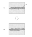
- FIG. 2 is a diagram showing an example of linear free lime.
- FIG. 3 is a diagram showing an example of planar free lime.
- FIG. 4 is a diagram showing the types of damage expression methods according to the type of damage, FIG. 4 (A) shows an image including cracks, and FIG. 4 (B) shows a polyline along the cracks. It is a figure which shows the image which was made.
- FIG. 5 is a diagram showing the types of damage expression methods according to the type of damage, FIG. 5 (A) shows an image including peeling and rebar exposure, and FIG. 5 (B) shows peeling and rebar exposure. It is a figure which shows the image in which the polygon surrounding the area of is drawn.
- FIG. 5 shows an image including peeling and rebar exposure
- FIG. 6 is a diagram showing the types of damage expression methods according to the type of damage
- FIG. 6 (A) shows an image containing planar free lime
- FIG. 6 (B) is a planar image. It is a figure which shows the image which the polygon surrounding the region of free lime is drawn.
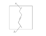
- FIG. 7 is a diagram showing each polyline when cracks and linear free lime, which are linear damages, are detected.
- FIG. 8 is a diagram used for explaining the proximity determination between the crack which is the linear damage shown in FIG. 7 and the linear free lime.
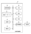
- FIG. 9 is a block diagram showing an example of the hardware configuration of the inspection support device according to the present invention.
- FIG. 10 is a conceptual diagram showing an embodiment of a damage detection processing unit configured by a CPU or the like.
- FIG. 10 is a conceptual diagram showing an embodiment of a damage detection processing unit configured by a CPU or the like.
- FIG. 11 is a perspective view showing an example of a bridge to be inspected.
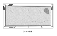
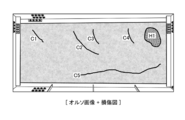
- FIG. 12 is a diagram showing an example of an orthoimage corresponding to a coffer, which is one of the inspection units of a bridge.
- FIG. 13 is a diagram showing an example of the damage detection result detected based on the ortho image shown in FIG.
- FIG. 14 is a diagram showing an example of an ortho image on which a damage diagram corresponding to a coffer is superimposed.
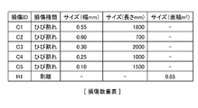
- FIG. 15 is a chart showing an example of a damage quantity table included in the damage detection result.
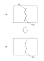
- FIG. 16 is a schematic view showing an example of the damage detection result of cracks and linear free lime by the damage detection processing unit and the output processing thereof.
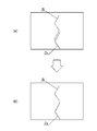
- FIG. 17 is a schematic view showing the damage detection results of cracks and linear free lime by the damage detection processing unit and other examples of the output processing thereof.
- FIG. 18 is a schematic view showing an example of the damage detection results of planar free lime and linear free lime by the damage detection processing unit and the output processing thereof.
- FIG. 19 is a schematic view showing the damage detection results of planar free lime and linear free lime by the damage detection processing unit, and other examples of the output processing thereof.
- FIG. 20 is a schematic view showing an example of the damage detection results of rust juice, planar free lime and water leakage by the damage detection processing unit, and the output processing thereof.
- FIG. 21 is a schematic view showing the damage detection results of rust juice, planar free lime and water leakage by the damage detection processing unit, and other examples of the output processing thereof.
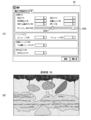
- FIG. 22 is an image diagram showing a GUI showing a second embodiment of damage detection result output, and is a diagram showing an example of a screen displayed on the display unit.
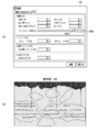
- FIG. 23 is an image diagram showing a GUI showing a second embodiment of damage detection result output, and is a diagram showing another example of a screen displayed on the display unit.
- FIG. 24 is an image diagram of a GUI showing a third embodiment of damage detection result output, and FIG. 24A shows a case where “10” is set as the transparency of the fill color of the damage image.
- FIG. 24 (B) is a diagram showing a composite image in which a damaged image having a transparency of “10” is superimposed and displayed on an image obtained by photographing the structure.
- FIG. 25 is an image diagram of a GUI showing a third embodiment of damage detection result output, and FIG. 25 (A) shows a case where “50” is set as the transparency of the fill color of the damage image.
- FIG. 25 (B) is a diagram showing a composite image in which a damaged image having a transparency of “50” is superimposed and displayed on an image obtained by photographing the structure.
- FIG. 26 is an image diagram of a GUI showing a third embodiment of damage detection result output, and FIG. 26A shows a case where “100” is set as the transparency of the fill color of the damage image.
- 26 (B) is a diagram showing a composite image in which a damaged image having a transparency of "100” is superimposed and displayed on an image obtained by photographing a structure.
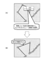
- FIG. 27 is a diagram showing a method of adding vertices to a polygon surrounding a damaged area.
- FIG. 28 is a diagram showing a method of removing vertices from polygons surrounding a damaged area.
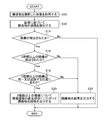
- FIG. 29 is a flowchart showing an embodiment of the inspection support method according to the present invention.
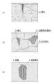
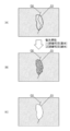
- FIG. 1 is a diagram showing an example of damage to a structure, and particularly shows damage to concrete members constituting the structure.
- FIG. 1 (A) shows water leakage A, which is one of the phenomena caused by damage to the concrete member.
- Leakage A is water leaking from the damaged portion due to damage to the concrete member (crack, crack at the joint, defective joint material, etc.).
- FIG. 1B shows cracks B, free lime C 1 , and rust juice D generated in the concrete member.
- Free lime C 1 is a phenomenon in which lime components flow out from the concrete member due to water leakage or the like and the lime component is exposed to the surface when the water evaporates.
- the rust juice D refers to a product in which a steel material such as a reinforcing bar inside a concrete member is corroded and a brown corrosion product exudes to the concrete surface.
- FIG. 1C shows the peeling E and the exposed reinforcing bar F generated in the concrete member.
- the peeling E means a state in which the concrete piece in the floating state is peeled off
- the reinforcing bar exposure F means a state in which the reinforcing bar in the concrete is exposed as a result of the peeling E.
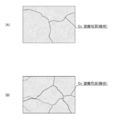
- FIG. 2 is a diagram showing an example of linear free lime
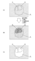
- FIG. 3 is a diagram showing an example of planar free lime.
- the linear free lime C 2 shown in FIGS. 2 (A) and 2 (B) is in a state where the cracks generated in the concrete member are clogged with the lime component. Therefore, the linear free lime C 2 and the crack have substantially the same shape, and the linear free lime C 2 is cracked at the same position (region) as the linear free lime C 2. There is.
- planar free lime shown in FIG. 3 (A) spreads below the crack as water leaks from the crack extending in the horizontal direction.
- the planar free lime C 1 shown in FIG. 3 (B) spreads around the cracks at the seams, and the planar free lime C 1 shown in FIG. 3 (C) spreads around the concrete cracks. There is.
- One aspect of the present invention detects damage to a structure from an image of the structure to be inspected, and outputs a damage detection result according to the type of the detected damage.
- FIGS. 4 to 6 are diagrams showing the types of damage expression methods according to the types of damage.
- FIG. 5 when peeling E and reinforcing bar exposure F are detected (FIG. 5 (A)), as a method of expressing peeling E and reinforcing bar exposure F, a closed line (polygon) surrounding the area of planar damage is used. ) Is represented by the drawing pattern (FIG. 5 (B)). This is because it is necessary to quantify the area in the case of planar damage such as peeling E.
- planar free lime C 1 when planar free lime C 1 is detected (FIG. 6 (A)), a closed line surrounding the area of planar damage is a way to represent planar free lime C 1. It is represented by a drawing pattern made of (polygons) (FIG. 6 (B)).
- planar free lime C 1 , peeling E, and rebar exposed F are all planar damages, but since the types of damage are different, polygons with different line types (for example, colors) can be identified. It is preferable to express it.
- the damage is expressed by a different drawing pattern according to the shape.
- linear free lime is represented by polylines
- planar free lime is represented by polygons.
- two or more types of damage may be detected from the same or adjacent positions on the structure (image).
- the adjacent position means a position where the distance between two or more types of damage is equal to or less than the threshold value.
- the threshold may be set by default or set by the user.
- FIG. 7 is a diagram showing each polyline when cracks and linear free lime, which are linear damages, are detected.
- X is a polyline showing cracks
- Y is a polyline showing linear free lime.
- FIG. 8 is a diagram used to explain the proximity judgment between the crack which is the linear damage shown in FIG. 7 and the linear free lime.
- the shortest distance between the point of interest P1 of the polyline X showing cracks (the first apex which is the end point of the polyline X) and the linear free lime polyline is L1.
- the shortest distance between the point of interest P2 (second vertex) of the poly line X and the poly line Y is L2
- the poly line X Let L3 be the shortest distance between the point of interest P3 (third vertex) and the polyline Y.
- the shortest distances of the two polylines X and Y are L4, L5, and L6, respectively.
- the shortest distance L4 is the shortest distance at the attention point 4 of the polyline Y (the apex which is the end point of the polyline Y)
- the shortest distance L5 is the attention point 5 of the polylines X and Y (the attention point 4 and the attention point 6).
- It is the shortest distance at the point of interest in the middle)
- the shortest distance L6 is the shortest distance at the point of interest 6 of the polyline X (the apex which is another end point of the polyline X).
- L1, L2, L3> threshold value is satisfied and L4, L5, L6 ⁇ threshold value is satisfied, it is determined that the two polylines Y and X (two damages) are “close” in the range of L4 to L6. do.
- the number of points of interest P1 to P6 is not limited to the above example.
- the distance between the two types of linear damage has been described, but the distance between the linear damage and the planar damage is also obtained by finding the shortest distance between each point of interest of the polyline and the polygon. , "Proximity" can be determined.
- priority is defined according to the type of damage, and when two or more types of damage are detected from the same or adjacent positions, the damage is expressed according to the priority. .. The details of the method of expressing damage according to the priority will be described later.
- FIG. 9 is a block diagram showing an example of the hardware configuration of the inspection support device according to the present invention.
- the inspection support device 10 shown in FIG. 1 a personal computer or a workstation can be used.
- the inspection support device 10 of this example mainly includes an image acquisition unit 12, an image database 14, a storage unit 16, an operation unit 18, a CPU (Central Processing Unit) 20, a RAM (Random Access Memory) 22, and a ROM. It is composed of (Read Only Memory) 24 and a display control unit 26.
- the image acquisition unit 12 corresponds to an input / output interface, and in this example, acquires a photographed image or the like of a structure to be inspected.
- the structures to be inspected include, for example, structures such as bridges and tunnels.
- the image acquired by the image acquisition unit 12 is, for example, a drone (unmanned flying object) equipped with a camera, a robot, or a large number of images (photographed image group) obtained by manually photographing a structure. It is preferable that the captured image group covers the entire structure and the adjacent captured images are duplicated.
- the captured image group acquired by the image acquisition unit 12 is stored in the image database 14.
- the storage unit 16 is a memory composed of a hard disk device, a flash memory, and the like.
- the storage unit 16 includes an operating system, an inspection support program, information indicating the priority of damage types, and a CAD (computer) indicating a structure. -aided design) Data and filed damage inspection results are stored.
- the damage inspection result can be stored as damage information in different layers for each type of damage.
- the damage information includes a damage diagram.
- the CAD data if the CAD data of the structure to be inspected exists, it can be used. When the CAD data of the structure does not exist, it can be automatically created based on the captured image group stored in the image database 14.
- the feature points between the captured images that overlap each other in the captured image group are extracted, and based on the extracted feature points, the feature points are extracted. It is possible to estimate the position and orientation of the camera mounted on the drone, and to generate a three-dimensional point cloud model in which the three-dimensional position of the feature point is estimated at the same time from the estimation result of the position and orientation of the camera.
- Structure from Motion which tracks the movement of a large number of feature points from a group of captured images in which the shooting position of the camera is moved by the drone, and simultaneously estimates the three-dimensional structure (Structure) and camera posture (Motion) of the structure.
- SfM three-dimensional structure
- bundle adjustment has been developed, and it has become possible to output with high accuracy.
- CAD data of the structure can be generated based on the generated 3D point cloud model.
- the operation unit 18 includes a keyboard, a mouse, and the like that are connected to the computer by wire or wirelessly, and functions as an operation unit that gives normal operation instructions to the computer.
- the operation unit 18 has a structure detected based on an image of the structure. It functions as an operation unit that edits the damage detection result of an object by user operation and sets the priority of a plurality of damage types of the structure by user operation. Details such as editing the damage detection result and setting the priority of the damage type will be described later.
- the CPU 20 reads various programs stored in the storage unit 16 or the ROM 24 or the like, controls each unit in an integrated manner, and detects damage to the structure (damage of two or more types) based on an image obtained by photographing the structure. It performs detection processing, determination processing for determining whether or not two or more types of damage are detected from the same or adjacent positions, and output processing for outputting the damage detection result detected by the damage detection processing.
- the damage detection process that detects two or more types of damage based on the captured image of the structure can be performed by artificial intelligence (AI).
- AI artificial intelligence
- a trained model by a convolutional neural network can be used.
- CNN convolutional neural network
- FIG. 10 is a conceptual diagram showing an embodiment of a damage detection processing unit configured by a CPU or the like.
- the damage detection processing unit 21 is composed of a plurality of (three in this example) trained models 21A, 21B, and 21C corresponding to a plurality of types of damage.
- Each trained model 21A, 21B, and 21C has an input layer, an intermediate layer, and an output layer, and each layer has a structure in which a plurality of "nodes" are connected by "edges".
- Image 13 of the structure is input to the input layer of CNN.
- the intermediate layer has a plurality of sets including a convolution layer and a pooling layer as one set, and is a portion for extracting features from an image input from an input layer.
- the convolution layer filters nearby nodes in the previous layer (performs a convolution operation using the filter) and acquires a "feature map”.
- the pooling layer reduces the feature map output from the convolution layer to a new feature map.
- the "convolution layer” plays a role of feature extraction such as edge extraction from an image, and the “pooling layer” plays a role of imparting robustness so that the extracted features are not affected by translation or the like.
- the output layer of CNN is the part that outputs the feature map showing the features extracted by the intermediate layer.
- the output layers of the trained models 21A, 21B, and 21C of this example are, for example, region classification (segmentation) in units of pixels for each damage of the structure shown in the image, or in units of a group of several pixels.
- the inference result is output as damage detection results 27A, 27B, 27C.
- the trained model 21A is a trained model machine-learned to detect damage to water leakage, planar free lime, and rust juice, and is a damaged region and damage of each of water leakage, planar free lime, and rust juice.
- the damage type for each area is output as a damage detection result (recognition result) 27A.
- the trained model 21B is a trained model machine-learned to detect damage of peeling / reinforcing bar exposure, and outputs the damaged areas of peeling / reinforcing bar exposure and the damage type for each damaged area as a damage detection result 27B. do.
- the trained model 21C is a trained model machine-learned to detect damage of cracks and linear free lime, and damage detection of each damaged region of cracks and linear free lime and the damage type for each damaged region. The result is output as 27C.
- the damage detection processing unit 21 is not limited to the above embodiment, for example, has an individual trained model for each damage type, and each trained model has a damage detection result corresponding to each damage type. It may be configured to output as. In this case, the same number of trained models as the number of damage types to be inspected will be provided. Further, it may have one trained model capable of dealing with all damage types, and may be configured to output the damage area and the damage type for each damage area as a damage detection result.
- the CPU 20 outputs the damage detection result detected by the damage detection process to the display unit (display) 30 via the display control unit 26 and displays it, or stores the damage detection result as a file. It is saved in the part (memory) 16.
- the RAM 22 is used as a work area of the CPU 20, and is used as a storage unit for temporarily storing the read program and various data.
- the display control unit 26 is a part that creates display data to be displayed on the display unit 30 and outputs it to the display unit 30.
- the damage detection result detected by the CPU 20 is displayed on the display unit 30, and the operation unit is operated.
- the display unit 30 displays a screen or the like for editing the damage detection result based on the user operation from 18.
- the display unit 30 uses various displays such as a liquid crystal monitor that can be connected to a computer, and displays an image of a structure input from the display control unit 26 as well as a damage detection result detected from the image. , Used as part of the user interface together with the operating unit 18.
- the processor including the CPU 20 of the inspection support device 10 having the above configuration performs each of the above processes by reading the inspection support program stored in the storage unit 16 or the ROM 24 and executing the inspection support program.
- FIG. 11 is a perspective view showing an example of a bridge to be inspected.
- the bridge 1 is provided in a direction orthogonal to the main girder 2 passed between the piers 7 and the main girder 2, and the horizontal girder 3 connecting the main girders and the main girder 2 are mutually connected. It is composed of various members including an anti-tilt structure 4 and a horizontal structure 5 connected to the main girder, and a floor slab 6 for traveling a vehicle or the like is placed on the upper part of the main girder or the like.
- the floor slab 6 is generally made of reinforced concrete.
- the floor slab 6 usually has a rectangular coffer defined by the main girder 2 and the cross girder 3 as a basic unit, and when inspecting damage to the floor slab (cracks, concrete peeling, etc.), the coffer It is done in units of intervals.
- Each coffer of the floor slab is one of the members (inspection unit) that make up the structure (bridge).
- the inspection unit of the bridge is the part / member classification (main girder 2, cross girder 3, anti-tilt structure 4, horizontal structure 5, pier 7 (column part, pillar)) that composes the structure. There are walls, beams, corners / joints)).
- the CPU 20 of the inspection support device 10 the inspection support program stored in the storage unit 16, the RAM 22 and ROM 24, the display control unit 26, and the like constitute a processor, and the processor performs various processes shown below.
- the processor performs an image acquisition process for acquiring an image of an inspection unit from a plurality of images of a structure (bridge 1) to be inspected stored in the image database 14.
- FIG. 12 is a diagram showing an example of an ortho image corresponding to a coffer, which is one of the inspection units of a bridge.
- the ortho image is an image of a structure (coffer) photographed and projected onto the surface of the coffer.
- a plurality of images corresponding to the coffer are extracted from the captured image group stored in the image database 14, the extracted plurality of images are panoramicly combined, and the panoramic composite image is obtained. It can be created by projecting to a coffered surface.
- the damage detection processing unit 21 shown in FIG. 10 inputs an ortho image (image 13) of the coffer, the damage detection processing unit 21 detects the damage in the coffer based on the input image 13 and outputs the damage detection results 27A to 27C. ..
- FIG. 13 is a diagram showing an example of damage detection results detected based on the ortho image shown in FIG.
- the damage detection result shown in FIG. 13 shows a damage diagram showing damage between the coffers to be inspected.
- the damage diagram shown in FIG. 13 shows five cracks C1 to C5 and concrete peeling H1.
- the damage diagram shown in FIG. 13 shows a drawing pattern with polylines along each of the cracks C1 to C5 (linear damage) detected on the ortho image, and a drawing pattern with polygons surrounding the region of peeling H1 (plane damage). Alternatively, it is represented by an image in which the inside of the polygon is filled.
- FIG. 14 is a diagram showing an example of an ortho image on which a damage diagram corresponding to a coffer is superimposed.
- the ortho image on which the damage diagram shown in FIG. 14 is superimposed can be created by superimposing the damage diagram shown in FIG. 13 on the ortho image shown in FIG. 12.
- the damage diagram can be created by attaching a color corresponding to the type of damage to the damaged part, and by superimposing the damage diagram on the ortho image, the damaged part can be easily visually recognized.
- FIG. 15 is a chart showing an example of a damage quantity table included in the damage detection result.
- the damage quantity table shown in FIG. 15 has items of damage identification information (ID: identification), damage type, size (width), size (length), and size (area), and each item corresponds to each damage. Information to be done is described.
- each crack C1 to C5 are quantified, and in the case of a peeling that is a planar damage, the area of the region of the peeling H1 is quantified. , This information is described in association with the damage ID.
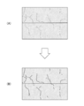
- FIG. 16 is a schematic view showing an example of the damage detection result of cracks and linear free lime by the damage detection processing unit and the output processing thereof.
- FIG. 16 (A) an image 13 is input to the flaw detection processing unit 21 (learned model 21C) shown in FIG. 10, each of the damaged region of the cracks B and linear free lime C 2 by a learned model 21C And the case where the damage detection result indicating the damage type for each damage area is detected is shown.
- the CPU 20 performs a determination process for determining whether or not these cracks B and the linear free lime C 2 are detected from the same or adjacent positions, respectively.
- the crack B and the linear free lime C 2 are shown side by side for convenience, but the linear free lime C 2 is formed on the crack B generated in the concrete member. It is in a state of being clogged with lime components. Therefore, the linear free lime C 2 and the crack B have substantially the same shape, and the linear free lime C 2 has a crack B at the same position (region) as the linear free lime C 2. doing.
- CPU 20 determines a free lime C 2 crack B and the line shape, to that detected from the same or adjacent locations . Then, when it is determined that the crack B and the linear free lime C 2 are detected from the same or adjacent positions, the CPU 20 performs an output process for outputting the damage detection result according to the priority of the damage type.
- the priority of the linear free lime C 2 is set higher than that of the crack B, so that the CPU 20 has the linear free lime as shown in FIG. 16 (B).
- the damage image in which the area of C 2 is filled is displayed on the display unit 30 via the display control unit 26, or the CAD data of the damage diagram showing the polyline of the linear free lime C 2 is output as a file. It is preferable that the CAD data file of the damage diagram is stored in the storage unit 16 in association with the image in which the damage is detected.
- FIG. 17 is a schematic diagram showing the damage detection results of cracks and linear free lime by the damage detection processing unit and other examples of the output processing thereof.
- the CPU 20 determines that a part of the crack B and a part of the linear free lime C 2 are detected from the same position. Then, the CPU 20 fills the area of the linear free lime C 2 with respect to the overlapping portion of the part of the crack B and the linear free lime C 2 as shown in FIG. 17 (B).
- the damage image is displayed on the display unit 30 via the display control unit 26, or the CAD data of the damage diagram showing the polyline of the linear free lime C 2 is output as a file.
- the CPU 20 causes the display unit 30 to display a damaged image in which the area of the crack B is filled as it is with the remaining portion of the crack B that does not overlap with the linear free lime C 2 via the display control unit 26.
- the CAD data of the damage diagram showing the polyline of the crack B is output as a file.
- the damage image and CAD data showing the crack B and the damage image and CAD data showing the linear free lime C 2 can be distinguished by changing the line type (for example, color), for example. ..
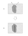
- FIG. 18 is a schematic view showing an example of the damage detection results of planar free lime and linear free lime by the damage detection processing unit and the output processing thereof.
- FIG. 18 damage detection processing unit 21 (trained model 21A, 21C) shown in FIG. 10 the image 13 respectively are inputted, the learned model 21A by planar free lime C 1 damaged region is detected is, the damaged region of the linear free lime C 2 is shown for when it is detected by the trained model 21C.
- the CPU 20 determines whether or not these planar free lime C 1 and linear free lime C 2 are detected from the same or adjacent positions, respectively.
- the CPU 20 and the planar free lime C 1 are generated. It is determined that the linear free lime C 2 is detected from the same or adjacent positions, respectively. Then, when it is determined that the planar free lime C 1 and the linear free lime C 2 are detected from the same or adjacent positions, the CPU 20 outputs the damage detection result according to the priority of the damage type. ..
- the CPU 20 has a surface as shown in FIG. 18 (B).
- the free lime C 1 planar give priority to the portion Jo of the free lime C 1 and linear free lime C 2 overlap, damaged images fill the damaged area of the planar free lime C1 a specific color Is displayed on the display unit 30 via the display control unit 26, and a damaged image in which a part of the non-overlapping linear free lime C 2 is filled is displayed on the display unit 30 via the display control unit 26.
- the polygon CPU20 for the free lime C 1 and the linear portion and the free lime C 2 overlap the planar as shown in FIG. 18 (C), which surrounds the planar damaged region of the free lime C 1 together with the CAD data, the CAD data of a part of polyline linear free non-overlapping lime C 2 to file output.
- FIG. 19 is a schematic view showing the damage detection results of planar free lime and linear free lime by the damage detection processing unit and other examples of the output processing thereof.
- the CPU 20 When a part of the planar free lime C 1 and the linear free lime C 2 overlap each other as shown in FIG. 19 (A), the CPU 20 has a planar free lime as shown in FIG. 19 (B).
- the damaged image in which the area of the linear free lime C 2 is filled is displayed with priority, and similarly, the linear free lime C 2 is displayed.
- Priority is given to the CAD data of the polyline of, and the file is output. In this case, for the planar free lime C 1, so that the damage image also CAD data is also not output.
- FIG. 20 is a schematic view showing an example of the damage detection results of rust juice, planar free lime and water leakage by the damage detection processing unit, and the output processing thereof.
- FIG. 20 (A) an image 13 is input to the flaw detection processing unit 21 (learned model 21A) shown in FIG. 10, rust juice D by trained model 21A, the planar free lime C 1 and leakage A It shows the case where the damaged area is detected.
- the CPU 20 determines whether or not these rust juice D, planar free lime C 1 and water leakage A are detected from the same or adjacent positions, respectively.
- the CPU 20 determines that these damages are detected from the same or adjacent positions, respectively. Then, when it is determined that the rust juice D, the planar free lime C 1 and the leak A are detected from the same or adjacent positions, the CPU 20 outputs the damage detection result according to the priority of the damage type.
- the CPU 20 since the priority is set to be lower in the order of rust juice D, planar free lime C 1 , and water leakage A, the CPU 20 has water leakage as shown in FIG. 20 (B). overlapping regions of free lime C 1 of planar over the a region, more overlapped regions of Sabijiru D on the surface of free lime C 1 regions, each region with a different color for each damage type The filled damage image is displayed on the display unit 30 via the display control unit 26. Further, as shown in FIG. 20C, the CPU 20 outputs CAD data of polygons surrounding each region of rust juice D, planar free lime C 1 , and water leakage A as a file.
- FIG. 21 is a schematic view showing the damage detection results of rust juice, planar free lime and water leakage by the damage detection processing unit, and other examples of the output processing thereof.
- the priorities of rust juice D, planar free lime C 1 , and water leakage A are set to be reversed as compared with the example shown in FIG.
- the priority is set to be lower in the order of free lime C 1 and rust juice D.
- the CPU 20 When all or part of the rust juice D, the planar free lime C 1 , and the leak A overlap each other as shown in FIG. 21 (A), the CPU 20 has a priority as shown in FIG. 21 (B). The damaged image that fills the area of water leakage A with the highest water leakage A is displayed with priority. In this case, rust juice D, planar free lime C 1 damage image existing in a region inside the leakage A is not displayed. Further, as shown in FIG. 21C, the CPU 20 gives priority to the CAD data of the polygon surrounding the region of the leak A having the highest priority and outputs the file. In this case, CAD data of rust juice D, a polygon surrounding the free lime C 1 planar present in the area inside the water leakage A will not be output.
- the priority of the damage type is not limited to the above example, but it is preferable to set the priority according to the severity of the damage (the one in which the damage is more advanced). For example, in the case of linear free lime and linear damage including cracks as damage types, linear free lime has a higher priority than cracks. In the case of planar damage including exposed reinforcing bars, peeling, rust juice, planar free lime, and water leakage, the priority is given to reinforcing bar exposure, peeling, rust juice, planar free lime, and water leakage. Is set low.
- the priority of the damage type may be appropriately set by the user using the operation unit 18.
- the CPU 20 performs a priority reception process for receiving the priority of the damage type of the structure from the operation unit 18 operated by the user, stores the received priority in the storage unit 16 or the like, and if necessary.
- the priority order can be read from the storage unit 16 and used.
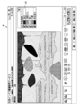
- FIG. 22 and 23 are image diagrams of a GUI (Graphical User Interface) showing a second embodiment of damage detection result output, respectively.
- FIG. 22 is a diagram showing an example of the screen 40 displayed on the display unit 30.
- a composite image in which a damaged image is superimposed on an image of a structure, a check box 42 for selecting a damage type to be displayed, and various icon buttons used for editing and the like are displayed.
- the damage detection result for each damage type detected by the damage detection processing unit 21 based on the photographed image of the structure can be retained as CAD data of the layer structure indicating the damage area for each damage type.
- the damage image corresponding to the damage type can be created by painting the damaged area with a color corresponding to the damage type based on the CAD data of the layer corresponding to the damage type.
- a color according to the damage type a color set in advance according to the damage type or a color set by the user can be used.
- FIG. 23 is a diagram showing another example of the screen 40 displayed on the display unit 30.
- the damage image displayed on the screen 40 is different from the example shown in FIG. 22.
- the screen 40 shown in FIG. 23 is different from the screen 40 shown in FIG. 22 in that the free lime and the damage image corresponding to the peeling are erased.
- the user can select one or a plurality of desired damage types to display a damage image showing the damage of the selected damage type. It is preferable that the check box 42 displays only one or a plurality of damage types detected from the image. Further, the method of displaying the damaged area for each type of damage is not limited to the embodiments shown in FIGS. 22 and 23.
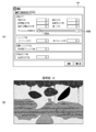
- [Third embodiment of damage detection result output] 24 to 26 are GUI image diagrams showing a third embodiment of damage detection result output, respectively.
- FIG. 24A is a diagram showing an example of a setting screen 44 for performing various settings.
- a “tab” for setting a color such as damage is selected, and by using this setting screen, the user can respond to the damage type shown in FIG. 22 and the like. You can set the color of the damaged image.
- the setting screen 44 shown in FIG. 24 (A) is provided with a knob 45A used for setting the transparency of the color (fill color) of the damaged image and a dialog box 45B for displaying the transparency.
- FIG. 24B is a diagram showing a composite image in which a damaged image having a transparency of “10” is superimposed and displayed on an image of a structure.
- the composite image shown in FIG. 24 (B) can be displayed by closing the setting screen after the transparency "10" is set on the setting screen shown in FIG. 24 (A).
- FIG. 25 (A) shows a setting screen in which the transparency is set to “50”
- FIG. 25 (B) is a composite image in which a damaged image having a transparency of “50” is superimposed and displayed on an image of a structure. It is a figure which shows.
- FIG. 26A shows a setting screen in which the transparency is set to “100”
- FIG. 26B shows a damaged image having the transparency “100” superimposed on the photographed image of the structure. It is a figure which shows the composite image.
- the user can visually recognize the image (damage) of the structure covered by the damaged image.
- the damaged area is classified in pixel units or in units of a group of several pixels, so it may lack accuracy. Further, it may be better to connect the cracks detected as two cracks as one crack. This is because it can be inferred that cracks are connected inside the concrete.
- the CPU 20 performs an edit instruction reception process for receiving an edit instruction for the damage detection result through an operation with the operation unit 18 (for example, a mouse) operated by the user, and edits the damage detection result according to the received edit instruction. Perform processing.
- the operation unit 18 for example, a mouse
- the editing may be performed by measuring the distance between the end points of polylines of the same type of linear damage after the damage detection process, and if the measured distance is less than the threshold value, the end points may be automatically connected. It may be automatically connected according to the instruction of the user.
- the threshold value may be a default value or may be user-configurable.
- a threshold value for the length and width of linear damage and a threshold value for the area of planar damage may be set, and damage detection results smaller than the threshold value may be automatically deleted.
- the damage detection result may be deleted automatically after the damage detection process, or may be deleted according to the user's instruction.
- the threshold value may be a default value or may be user-configurable.
- FIG 27 and 28 are diagrams showing an editing example of the damage detection result, respectively.
- the transparency of the color that fills the damage image is set high, and the image of the structure is easily visible. Is preferable.
- FIG. 27 is a diagram showing a method of adding vertices to the polygon surrounding the damaged area.
- the polygon is drawn by connecting a plurality of vertices (vertices indicated by squares in FIG. 27) along the damaged area.
- FIG. 28 is a diagram showing a method of deleting vertices from polygons surrounding a damaged area.
- the entire polyline or polygon can be selected by clicking the line connecting the vertices, and the entire polyline or polygon can be deleted at once. Has a function to newly add.
- FIG. 29 is a flowchart showing an embodiment of the inspection support method according to the present invention.
- each step shown in FIG. 29 is performed by, for example, a processor configured by the CPU 20 of the inspection support device 10 shown in FIG.
- the processor acquires an image of the structure to be inspected from the image acquisition unit 12, the image database 14, or the like (step S10).
- the damage detection processing unit 21 detects damage to the structure based on the image acquired in step S10 (step S12).
- the processor determines whether or not the damage is detected by the damage detection performed in step S12 (step S14), and if the damage is detected (in the case of “Yes”), two or more types of damage are detected. It is determined whether or not it has been detected (step S16).
- step S16 When it is determined in step S16 that two or more types of damage are detected (in the case of "Yes"), the processor further damages two or more types of the two or more types of damage from the same or adjacent positions. Is determined (step S18).
- the processor outputs the damage detection result according to the priority of the damage types. (Step S20).
- the damage detection result is output, for example, by superimposing the damage image on the image, displaying the damage image alone on the display unit, or outputting the CAD data showing the damage diagram as a file.
- step S16 when two or more types of damage are not detected in step S16 (in the case of "No"), that is, when only one type of damage is detected, or when two or more types of damage are detected in step S18, the same or close to each other. If it is determined that the damage has not been detected from the position (in the case of "No"), the process proceeds to step S22, and in step S22, one or two or more types of damage detection results are output as they are.
- the hardware that realizes the inspection support device according to the present invention can be configured by various processors.
- Various processors include CPUs (Central Processing Units), which are general-purpose processors that execute programs and function as various processing units, and FPGAs (Field Programmable Gate Arrays), which can change the circuit configuration after manufacturing. It includes a dedicated electric circuit which is a processor having a circuit configuration specially designed for executing a specific process such as a programmable logic device (PLD) and an ASIC (Application Specific Integrated Circuit).
- One processing unit constituting the inspection support device may be composed of one of the above-mentioned various processors, or may be composed of two or more processors of the same type or different types.
- one processing unit may be composed of a plurality of FPGAs or a combination of a CPU and an FPGA.
- a plurality of processing units may be configured by one processor.
- one processor is configured by a combination of one or more CPUs and software, as represented by a computer such as a client or a server.
- a processor functions as a plurality of processing units.
- SoC System On Chip
- a processor that realizes the functions of the entire system including a plurality of processing units with one IC (Integrated Circuit) chip is used. be.
- the various processing units are configured by using one or more of the above-mentioned various processors as a hardware-like structure.
- the hardware structure of these various processors is, more specifically, an electric circuit (circuitry) in which circuit elements such as semiconductor elements are combined.
- the present invention also includes an inspection support program that causes the computer to function as an inspection support device according to the present invention by being installed in the computer, and a storage medium in which the inspection support program is recorded.
Landscapes
- Engineering & Computer Science (AREA)
- Theoretical Computer Science (AREA)
- Computer Vision & Pattern Recognition (AREA)
- Physics & Mathematics (AREA)
- General Physics & Mathematics (AREA)
- General Health & Medical Sciences (AREA)
- Multimedia (AREA)
- Health & Medical Sciences (AREA)
- Databases & Information Systems (AREA)
- Computing Systems (AREA)
- Software Systems (AREA)
- Medical Informatics (AREA)
- Evolutionary Computation (AREA)
- Artificial Intelligence (AREA)
- Pathology (AREA)
- Chemical & Material Sciences (AREA)
- Biochemistry (AREA)
- Immunology (AREA)
- Analytical Chemistry (AREA)
- Life Sciences & Earth Sciences (AREA)
- Signal Processing (AREA)
- Quality & Reliability (AREA)
- Investigating Materials By The Use Of Optical Means Adapted For Particular Applications (AREA)
Abstract
Provided are an inspection support device, method, and program with which, if two or more types of damage are detected from a structure, in particular if two or more types of damage are detected from the same or similar positions in a structure, the results of the detection of the damage can be output satisfactorily. A processor of the inspection support device acquires an image obtained by imaging a structure to be inspected, and detects damage to the structure on the basis of the acquired image. If two or more types of damage to the structure (a crack B and a thread-like free lime C2) are detected, the processor detects whether the two or more types of damage have been detected from the same or adjacent positions. When outputting the damage detection results (damage image, damage drawing or the like), if it has been determined that the crack B and the thread-like free lime C2 have been detected from the same or adjacent positions, the processor preferentially outputs the damage detection result for the thread-like free lime C2 in accordance with an order of priority of the damage types (figure 14(B)).
Description
本発明は点検支援装置、方法及びプログラムに係り、特に構造物の点検を支援する技術に関する。
The present invention relates to an inspection support device, a method and a program, and particularly to a technique for supporting the inspection of a structure.
橋梁などの社会インフラ構造物は、維持管理及び補修を行うために定期点検する必要がある。
Social infrastructure structures such as bridges need to be inspected regularly for maintenance and repair.
特許文献1には、トンネルの内部壁面をカメラで撮影し、撮影した画像を画像処理することにより内部壁面の小区分毎にひび割れの抽出・定量化を行い、小区分毎にひび割れ情報を表示するひび割れ検出方法及びその表示方法が開示されている。例えば、小区分毎のひび割れの程度に応じて、小区分毎にひび割れを色分けして表示し、これにより、ひび割れの程度を把握しやすいようにしている。
In Patent Document 1, the inner wall surface of the tunnel is photographed with a camera, and the captured image is image-processed to extract and quantify cracks in each subdivision of the inner wall surface, and crack information is displayed for each subdivision. A crack detection method and a display method thereof are disclosed. For example, the cracks are displayed in different colors for each subdivision according to the degree of cracks in each subdivision, so that the degree of cracks can be easily grasped.
ところで、構造物の損傷には、ひび割れ以外にも多くの種類の損傷が存在する。例えば、構造物のコンクリート部位では、ひび割れの他に、漏水、遊離石灰、錆汁、剥離、鉄筋露出等の多項目の損傷があり、同様に構造物の鋼部材では、亀裂、腐食、防食機能の劣化等の多項目の損傷がある。
By the way, there are many types of damage to structures other than cracks. For example, in addition to cracks, there are many damages such as water leakage, free lime, rust juice, peeling, and exposed reinforcing bars in the concrete part of the structure. Similarly, in the steel member of the structure, there are cracks, corrosion, and anticorrosion functions. There are many items of damage such as deterioration of.
特許文献1には、小区分毎のひび割れの程度に応じて、小区分毎にひび割れを色分けして表示する記載があるが、構造物から2種類以上(多項目)の損傷を検出する記載がなく、多項目の損傷の検出結果の出力方法についても記載されていない。
In Patent Document 1, there is a description that cracks are displayed in different colors for each sub-category according to the degree of cracks in each sub-category, but there is a description that two or more types (multi-items) of damage are detected from a structure. There is no description on how to output the detection results of multi-item damage.
本発明はこのような事情に鑑みてなされたもので、構造物から2種類以上の損傷が検出され、特に構造物の同一又は近接する位置から2種類以上の損傷が検出された場合に、その損傷検出結果を良好に出力することができる点検支援装置、方法及びプログラムを提供することを目的とする。
The present invention has been made in view of such circumstances, and when two or more types of damage are detected in a structure, and in particular, two or more types of damage are detected from the same or adjacent positions of the structure. It is an object of the present invention to provide an inspection support device, a method and a program capable of outputting damage detection results satisfactorily.
上記目的を達成するために第1態様に係る発明は、プロセッサを備えた点検支援装置であって、プロセッサは、点検対象の構造物を撮影した画像を取得する画像取得処理と、取得した画像に基づいて構造物の損傷を検出する損傷検出処理と、損傷検出処理により構造物の2種類以上の損傷が検出された場合に、2種類以上の損傷のうち、同一又は近接する位置から2種類以上の損傷が検出されたか否かを判定する判定処理と、損傷検出処理により検出された損傷検出結果を出力する出力処理であって、判定処理により、同一又は近接する位置から2種類以上の損傷がされたことが判定されると、損傷種類の優先順位にしたがって損傷検出結果を出力する出力処理と、を行う。
In order to achieve the above object, the invention according to the first aspect is an inspection support device including a processor, in which the processor acquires an image of a structure to be inspected, an image acquisition process, and the acquired image. When two or more types of damage to a structure are detected by the damage detection process that detects damage to the structure based on the damage detection process, two or more types of damage from the same or adjacent positions among the two or more types of damage. It is a judgment process that determines whether or not the damage is detected, and an output process that outputs the damage detection result detected by the damage detection process. When it is determined that the damage has been performed, an output process for outputting the damage detection result according to the priority of the damage type is performed.
本発明の第1態様によれば、点検対象の構造物を撮影した画像に基づいて構造物の2種類以上の損傷が検出され、特に構造物の同一又は近似する位置から2種類以上の損傷が検出された場合には、損傷検出結果として優先順位にしたがって損傷検出結果を出力する。これにより、構造物の同一又は近接する位置から2種類以上の損傷が検出された場合には、損傷種類の優先順位にしたがって損傷検出結果を出力することで、構造物の同一又は近接する位置から2種類以上の損傷が検出された場合に対応することができる。尚、2種類以上の損傷が構造物の同一又は近接する位置にない場合には、2種類以上の損傷検出結果はそのまま出力することができる。
According to the first aspect of the present invention, two or more types of damage to the structure are detected based on an image of the structure to be inspected, and in particular, two or more types of damage are detected from the same or similar positions of the structure. If it is detected, the damage detection result is output according to the priority as the damage detection result. As a result, when two or more types of damage are detected from the same or close positions of the structure, the damage detection results are output according to the priority of the damage types, so that the damage detection results are output from the same or close positions of the structure. It is possible to deal with the case where two or more types of damage are detected. When two or more types of damage are not located at the same or close to each other in the structure, the two or more types of damage detection results can be output as they are.
本発明の第2態様に係る点検支援装置において、損傷検出処理は、画像に基づいて損傷領域及び損傷領域毎の損傷種類を検出し、判定処理は、損傷検出処理により、同一又は近接する損傷領域で2種類以上の損傷種類が検出されたか否かを判定し、出力処理は、判定処理により、同一又は近接する損傷領域で2種類以上の損傷種類が検出されたことが判定されると、同一又は近接する損傷領域の損傷検出結果として最も優先順位が高い損傷種類の損傷検出結果を出力することが好ましい。構造物の同一又は近接する位置から2種類以上の損傷が検出された場合、最も優先順位が高い損傷種類の損傷検出結果を出力し、ユーザ等に報知することが有効だからである。
In the inspection support device according to the second aspect of the present invention, the damage detection process detects the damaged area and the damage type for each damaged area based on the image, and the determination process is the same or adjacent damage area by the damage detection process. Determines whether or not two or more types of damage have been detected, and the output process is the same when it is determined by the determination process that two or more types of damage have been detected in the same or adjacent damage areas. Alternatively, it is preferable to output the damage detection result of the damage type having the highest priority as the damage detection result of the adjacent damage area. This is because when two or more types of damage are detected from the same or adjacent positions of the structure, it is effective to output the damage detection result of the damage type having the highest priority and notify the user or the like.
本発明の第3態様に係るにおいて、近接する位置は、2種類以上の損傷間の距離が閾値以下になる位置であることが好ましい。
In the third aspect of the present invention, it is preferable that the adjacent positions are positions where the distance between two or more types of damage is equal to or less than the threshold value.
本発明の第4態様に係る点検支援装置において、損傷検出処理は、画像を入力すると、損傷領域及び損傷領域毎の損傷種類を認識結果として出力する学習済みモデルが実行することが好ましい。
In the inspection support device according to the fourth aspect of the present invention, it is preferable that the damage detection process is executed by a trained model that outputs the damage area and the damage type for each damage area as a recognition result when an image is input.
本発明の第5態様に係る点検支援装置において、出力処理は、損傷種類が線状損傷の場合と、損傷種類が面状損傷の場合とで、異なる描画パターンを出力することが好ましい。
In the inspection support device according to the fifth aspect of the present invention, it is preferable that the output process outputs different drawing patterns depending on whether the damage type is linear damage or the damage type is planar damage.
本発明の第6態様に係る点検支援装置において、出力処理は、損傷種類が線状損傷の場合、線状損傷を閉じない線を示す損傷図を出力し、損傷種類が面状損傷の場合、面状損傷を囲む閉じた線を示す損傷図を出力することが好ましい。線画の描画パターンで損傷図を出力する場合、線状損傷の場合、線状損傷を閉じない線を示す損傷図とし、損傷種類が面状損傷の場合、面状損傷を囲む閉じた線を示す損傷図とする。
In the inspection support device according to the sixth aspect of the present invention, the output process outputs a damage diagram showing a line showing a line that does not close the linear damage when the damage type is linear damage, and when the damage type is planar damage. It is preferable to output a damage diagram showing a closed line surrounding the planar damage. When outputting a damage diagram with a line drawing drawing pattern, in the case of linear damage, a damage diagram showing a line that does not close the linear damage is used, and if the damage type is planar damage, a closed line surrounding the planar damage is shown. It is a damage diagram.
本発明の第7態様に係る点検支援装置において、出力処理は、損傷種類が線状損傷の場合、少なくとも線状損傷を塗り潰した損傷画像を出力し、損傷種類が面状損傷の場合、少なくとも面状損傷を塗り潰した損傷画像を出力することが好ましい。
In the inspection support device according to the seventh aspect of the present invention, the output process outputs a damage image in which at least the linear damage is filled when the damage type is linear damage, and at least a surface when the damage type is surface damage. It is preferable to output a damage image in which the shape damage is filled.
本発明の第8態様に係る点検支援装置において、出力処理は、損傷検出結果をディスプレイに出力して表示させ、又は損傷検出結果をファイルにしてメモリに保存させることが好ましい。
In the inspection support device according to the eighth aspect of the present invention, it is preferable that the output process outputs the damage detection result to the display and displays it, or saves the damage detection result as a file in the memory.
本発明の第8態様に係る点検支援装置において、損傷種類の優先順位は、損傷の重大度に応じて予め設定された優先順位であることが好ましい。
In the inspection support device according to the eighth aspect of the present invention, the priority of the damage type is preferably a preset priority according to the severity of the damage.
本発明の第9態様に係る点検支援装置において、損傷種類として、線状の遊離石灰、及びひび割れを含む線状損傷の場合、線状の遊離石灰は、ひび割れよりも優先順位が高い。
In the inspection support device according to the ninth aspect of the present invention, in the case of linear free lime and linear damage including cracks as damage types, the linear free lime has a higher priority than cracks.
本発明の第10態様に係る点検支援装置において、損傷種類として、鉄筋露出、剥離、
錆汁、面状の遊離石灰、及び漏水を含む面状損傷の場合、鉄筋露出、剥離、錆汁、面状の遊離石灰、及び漏水の順に優先順位が低く設定される。 In the inspection support device according to the tenth aspect of the present invention, the types of damage include exposure of reinforcing bars, peeling, and so on.
In the case of planar damage including rust juice, planar free lime, and water leakage, the priority is set in the order of reinforcing bar exposure, peeling, rust juice, planar free lime, and water leakage.
本発明の第12態様に係る点検支援装置において、プロセッサは、ユーザにより操作される操作部から構造物の損傷種類の優先順位を受け付ける優先順位受付処理を行い、損傷種類の優先順位は、ユーザから操作部を介して受け付けた優先順位である。
In the inspection support device according to the twelfth aspect of the present invention, the processor performs a priority reception process for receiving the priority of the damage type of the structure from the operation unit operated by the user, and the priority of the damage type is determined by the user. This is the priority received via the operation unit.
本発明の第13態様に係る点検支援装置において、プロセッサは、ユーザにより操作される操作部から損傷検出結果の編集指示を受け付ける編集指示受付処理と、受け付けた編集指示にしたがって損傷検出結果を編集する編集処理と、を行うことが好ましい。
In the inspection support device according to the thirteenth aspect of the present invention, the processor edits the damage detection result according to the edit instruction reception process for receiving the edit instruction of the damage detection result from the operation unit operated by the user and the received edit instruction. It is preferable to perform an editing process.
本発明の第14態様に係る点検支援装置において、損傷検出結果は、損傷識別情報、損傷種類及びサイズの項目を有し、検出した損傷毎に各項目に対応する情報が記載された損傷数量表を含むことが好ましい。
In the inspection support device according to the 14th aspect of the present invention, the damage detection result has items of damage identification information, damage type and size, and a damage quantity table in which information corresponding to each item is described for each detected damage. Is preferably included.
第15態様に係る発明は、プロセッサにより点検対象の構造物の点検支援を行う点検支援方法であって、プロセッサの各処理は、点検対象の構造物を撮影した画像を取得するステップと、取得した画像に基づいて構造物の2種類以上の損傷を検出するステップと、検出された構造物の2種類以上の損傷のうち、同一又は近接する位置から2種類以上の損傷が検出されたか否かを判定するステップと、検出された損傷検出結果を出力するステップであって、判定するステップにより、同一又は近接する位置から2種類以上の損傷が検出されたことが判定されると、損傷種類の優先順位にしたがって損傷検出結果を出力するステップと、を含む。
The invention according to the fifteenth aspect is an inspection support method for supporting inspection of a structure to be inspected by a processor, and each process of the processor includes a step of acquiring an image of the structure to be inspected and the acquisition. A step of detecting two or more types of damage to a structure based on an image, and whether or not two or more types of damage are detected from the same or adjacent positions among the two or more types of damage of the detected structure. In the step of determining and the step of outputting the detected damage detection result, if it is determined by the determination step that two or more types of damage are detected from the same or adjacent positions, the damage type is prioritized. It includes a step of outputting the damage detection result according to the order.
第16態様に係る発明は、点検対象の構造物の点検支援を行う方法をコンピュータに実行させる点検支援プログラムであって、方法は、点検対象の構造物を撮影した画像を取得するステップと、取得した画像に基づいて構造物の2種類以上の損傷を検出するステップと、検出された構造物の2種類以上の損傷のうち、同一又は近接する位置から2種類以上の損傷が検出されたか否かを判定するステップと、検出された損傷検出結果を出力するステップであって、判定するステップにより、同一又は近接する位置から2種類以上の損傷が検出されたことが判定されると、損傷種類の優先順位にしたがって損傷検出結果を出力するステップと、を含む。
The invention according to the 16th aspect is an inspection support program for causing a computer to execute a method of performing inspection support for a structure to be inspected, wherein the method includes a step of acquiring an image of the structure to be inspected and acquisition. Whether or not two or more types of damage were detected from the same or adjacent positions among the two or more types of damage of the detected structure and the step of detecting two or more types of damage to the structure based on the obtained image. And a step to output the detected damage detection result. If it is determined by the determination step that two or more types of damage are detected from the same or adjacent positions, the damage type is determined. It includes a step of outputting the damage detection result according to the priority.
本発明によれば、構造物から2種類以上の損傷が検出され、特に構造物の同一又は近接する位置から2種類以上の損傷が検出された場合に、その損傷検出結果を良好に出力することができる。
According to the present invention, when two or more types of damage are detected from a structure, and particularly when two or more types of damage are detected from the same or adjacent positions of the structure, the damage detection result is satisfactorily output. Can be done.
以下、添付図面に従って本発明に係る点検支援装置、方法及びプログラムの好ましい実施形態について説明する。
Hereinafter, preferred embodiments of the inspection support device, method, and program according to the present invention will be described with reference to the accompanying drawings.
[本発明の概要]
図1は、構造物の損傷の一例を示す図であり、特に構造物を構成するコンクリート部材の損傷に関して示している。 [Outline of the present invention]
FIG. 1 is a diagram showing an example of damage to a structure, and particularly shows damage to concrete members constituting the structure.
図1は、構造物の損傷の一例を示す図であり、特に構造物を構成するコンクリート部材の損傷に関して示している。 [Outline of the present invention]
FIG. 1 is a diagram showing an example of damage to a structure, and particularly shows damage to concrete members constituting the structure.
図1(A)は、コンクリート部材の損傷が原因で発生した現象の一つである漏水Aを示している。漏水Aは、コンクリート部材の損傷(ひび割れ、打ち継ぎ目のひび割れ、目地材の不良等)が原因で、その損傷部分から水が漏れ出たものである。
FIG. 1 (A) shows water leakage A, which is one of the phenomena caused by damage to the concrete member. Leakage A is water leaking from the damaged portion due to damage to the concrete member (crack, crack at the joint, defective joint material, etc.).
図1(B)は、コンクリート部材に発生したひび割れB、遊離石灰C1、及び錆汁Dを示している。遊離石灰C1とは、漏水等によりコンクリート部材内から流れ出し、水分が蒸発する際に石灰成分が表面に出る現象をいう。また、錆汁Dは、コンクリート部材の内部の鉄筋等の鋼材が腐食して、茶色の腐食生成物がコンクリート表面に滲み出たものをいう。
FIG. 1B shows cracks B, free lime C 1 , and rust juice D generated in the concrete member. Free lime C 1 is a phenomenon in which lime components flow out from the concrete member due to water leakage or the like and the lime component is exposed to the surface when the water evaporates. Further, the rust juice D refers to a product in which a steel material such as a reinforcing bar inside a concrete member is corroded and a brown corrosion product exudes to the concrete surface.
図1(C)は、コンクリート部材に発生した剥離E及び鉄筋露出Fを示している。剥離Eとは、浮き状態にあったコンクリート片が剥がれ落ちた状態をいい、鉄筋露出Fとは、剥離Eの結果、コンクリート内の鉄筋が露出した状態をいう。
FIG. 1C shows the peeling E and the exposed reinforcing bar F generated in the concrete member. The peeling E means a state in which the concrete piece in the floating state is peeled off, and the reinforcing bar exposure F means a state in which the reinforcing bar in the concrete is exposed as a result of the peeling E.
また、図示しないが、構造物を構成する鋼部材の損傷としては、亀裂、腐食、破断、防食機能の劣化等の損傷の種類がある。
Although not shown, there are types of damage such as cracks, corrosion, breakage, and deterioration of anticorrosion function as damages to the steel members constituting the structure.
図2は、線状の遊離石灰の一例を示す図であり、図3は、面状の遊離石灰の一例を示す図である。
FIG. 2 is a diagram showing an example of linear free lime, and FIG. 3 is a diagram showing an example of planar free lime.
図2(A)及び(B)に示す線状の遊離石灰C2は、コンクリート部材に発生したひび割れに石灰成分が詰まっている状態のものである。したがって、線状の遊離石灰C2とひび割れとは略同じ形状であり、線状の遊離石灰C2には、その線状の遊離石灰C2と同一の位置(領域)にひび割れが発生している。
The linear free lime C 2 shown in FIGS. 2 (A) and 2 (B) is in a state where the cracks generated in the concrete member are clogged with the lime component. Therefore, the linear free lime C 2 and the crack have substantially the same shape, and the linear free lime C 2 is cracked at the same position (region) as the linear free lime C 2. There is.
図3(A)に示す面状の遊離石灰は、水平方向に延びるひび割れからの漏水にしたがってひび割れの下方に拡がっている。図3(B)に示す面状の遊離石灰C1は、打ち継ぎ目のひび割れを中心に拡がっており、図3(C)に示す面状の遊離石灰C1は、コンクリートひび割れを中心に拡がっている。
The planar free lime shown in FIG. 3 (A) spreads below the crack as water leaks from the crack extending in the horizontal direction. The planar free lime C 1 shown in FIG. 3 (B) spreads around the cracks at the seams, and the planar free lime C 1 shown in FIG. 3 (C) spreads around the concrete cracks. There is.
本発明の一態様は、点検対象の構造物を撮影した画像から構造物の損傷を検出し、検出した損傷の種類にしたがって損傷検出結果を出力する。
One aspect of the present invention detects damage to a structure from an image of the structure to be inspected, and outputs a damage detection result according to the type of the detected damage.
図4から図6は、損傷の種類に応じた損傷の表現方法の種類を示す図である。
FIGS. 4 to 6 are diagrams showing the types of damage expression methods according to the types of damage.
図4に示すように、ひび割れが検出された場合(図4(A))、ひび割れを表現する方法として、ひび割れに沿った閉じない線(ポリライン)による描画パターンで表現する(図4(B))。ひび割れのように線状の損傷の場合、長さの定量化が必要だからである。
As shown in FIG. 4, when a crack is detected (FIG. 4 (A)), the crack is expressed by a drawing pattern with a non-closing line (polyline) along the crack (FIG. 4 (B)). ). This is because in the case of linear damage such as cracks, it is necessary to quantify the length.
したがって、図2に示したように線状の遊離石灰が検出された場合も、線状の遊離石灰を表現する方法としては、線状の遊離石灰に沿ったポリラインの描画パターンで出力する。また、ひび割れと線状の遊離石灰とは、いずれも線状の損傷であるが、損傷の種類が異なるため、線種(例えば、色)が異なるポリラインで識別可能に表現することが好ましい。
Therefore, even when linear free lime is detected as shown in FIG. 2, as a method of expressing linear free lime, a polyline drawing pattern along the linear free lime is output. Further, the crack and the linear free lime are both linear damages, but since the types of damages are different, it is preferable to express them identifiable by polylines having different line types (for example, colors).
図5に示すように、剥離E及び鉄筋露出Fが検出された場合(図5(A))、剥離E及び鉄筋露出Fを表現する方法として、面状損傷の領域を囲む閉じた線(ポリゴン)による描画パターンで表現する(図5(B))。剥離E等の面状損傷の場合、面積の定量化が必要だからである。
As shown in FIG. 5, when peeling E and reinforcing bar exposure F are detected (FIG. 5 (A)), as a method of expressing peeling E and reinforcing bar exposure F, a closed line (polygon) surrounding the area of planar damage is used. ) Is represented by the drawing pattern (FIG. 5 (B)). This is because it is necessary to quantify the area in the case of planar damage such as peeling E.
図6に示すように、面状の遊離石灰C1が検出された場合(図6(A))、面状の遊離石灰C1を表現する方法として、面状損傷の領域を囲む閉じた線(ポリゴン)による描画パターンで表現する(図6(B))。
As shown in FIG. 6, when planar free lime C 1 is detected (FIG. 6 (A)), a closed line surrounding the area of planar damage is a way to represent planar free lime C 1. It is represented by a drawing pattern made of (polygons) (FIG. 6 (B)).
尚、面状の遊離石灰C1、剥離E、及び鉄筋露出Fは、いずれも面状の損傷であるが、損傷の種類が異なるため、線種(例えば、色)が異なるポリゴンで識別可能に表現することが好ましい。
The planar free lime C 1 , peeling E, and rebar exposed F are all planar damages, but since the types of damage are different, polygons with different line types (for example, colors) can be identified. It is preferable to express it.
本発明の一態様では、同じ損傷と分類されるものであっても、損傷の形状が異なる場合には損傷の種類が異なるものとし、その形状に応じて異なる描画パターンで表現する。例えば、線状の遊離石灰は、ポリラインで表現し、面状の遊離石灰は、ポリゴンで表現する。
In one aspect of the present invention, even if the damage is classified as the same damage, if the shape of the damage is different, the type of damage is different, and the damage is expressed by a different drawing pattern according to the shape. For example, linear free lime is represented by polylines, and planar free lime is represented by polygons.
また、構造物(画像)上で、同一又は近接する位置から2種類以上の損傷が検出さる場合がある。ここで、近接する位置とは、2種類以上の損傷間の距離が閾値以下になる位置をいう。閾値は、デフォルトで決められていてもよいし、ユーザが設定してもよい。
In addition, two or more types of damage may be detected from the same or adjacent positions on the structure (image). Here, the adjacent position means a position where the distance between two or more types of damage is equal to or less than the threshold value. The threshold may be set by default or set by the user.
例えば、線状の遊離石灰の場合、線状の遊離石灰とコンクリートひび割れとが重なり、同一の位置に2つの損傷が検出されることになる。また、図5に示したように剥離Eと鉄筋露出Fの場合、鉄筋露出Fは、剥離E内に存在する。したがって、鉄筋露出Fと剥離Eの2つの損傷間の距離は閾値以下となり、両者は近接する位置の損傷である。
For example, in the case of linear free lime, linear free lime and concrete cracks overlap, and two damages are detected at the same position. Further, as shown in FIG. 5, in the case of the peeling E and the reinforcing bar exposed F, the reinforcing bar exposed F exists in the peeling E. Therefore, the distance between the two damages of the reinforcing bar exposure F and the peeling E is equal to or less than the threshold value, and both are damages at positions close to each other.
図7は、線状損傷であるひび割れと線状の遊離石灰とが検出された場合の各々のポリラインを示す図である。
FIG. 7 is a diagram showing each polyline when cracks and linear free lime, which are linear damages, are detected.
図7において、Xは、ひび割れを示すポリラインであり、Yは、線状の遊離石灰を示すポリラインである。
In FIG. 7, X is a polyline showing cracks, and Y is a polyline showing linear free lime.
図8は、図7に示した線状損傷であるひび割れと線状の遊離石灰との近接判断を説明するために用いた図である。
FIG. 8 is a diagram used to explain the proximity judgment between the crack which is the linear damage shown in FIG. 7 and the linear free lime.
以下、図8を参照にして、ひび割れと線状の遊離石灰の2つの損傷の「近接」の判定例について説明する。
Hereinafter, with reference to FIG. 8, an example of determining “proximity” between two damages of crack and linear free lime will be described.
図8(A)に示すように、ひび割れを示すポリラインXの注目点P1(ポリラインXの端点である1番目の頂点)と、線状の遊離石灰のポリラインとの最短距離をL1とする。
As shown in FIG. 8A, the shortest distance between the point of interest P1 of the polyline X showing cracks (the first apex which is the end point of the polyline X) and the linear free lime polyline is L1.
同様にして図8(B)に示すように、ポリラインXの注目点P2(2番目の頂点)と、ポリラインYとの最短距離をL2とし、図8(C)に示すように、ポリラインXの注目点P3(3番目の頂点)と、ポリラインYとの最短距離をL3とする。
Similarly, as shown in FIG. 8 (B), the shortest distance between the point of interest P2 (second vertex) of the poly line X and the poly line Y is L2, and as shown in FIG. 8 (C), the poly line X Let L3 be the shortest distance between the point of interest P3 (third vertex) and the polyline Y.
また、図8(D)~(F)に示すように、2つのポリラインX、Yにおける各最短距離をそれぞれL4,L5,L6とする。尚、最短距離L4は、ポリラインYの注目点4(ポリラインYの端点である頂点)における最短距離であり、最短距離L5は、ポリラインX、Yの注目点5(注目点4と注目点6の中間の注目点)における最短距離であり、最短距離L6は、ポリラインXの注目点6(ポリラインXの他の端点である頂点)における最短距離である。
Further, as shown in FIGS. 8 (D) to 8 (F), the shortest distances of the two polylines X and Y are L4, L5, and L6, respectively. The shortest distance L4 is the shortest distance at the attention point 4 of the polyline Y (the apex which is the end point of the polyline Y), and the shortest distance L5 is the attention point 5 of the polylines X and Y (the attention point 4 and the attention point 6). It is the shortest distance at the point of interest in the middle), and the shortest distance L6 is the shortest distance at the point of interest 6 of the polyline X (the apex which is another end point of the polyline X).
そして、L1,L2,L3>閾値を満たし、L4,L5,L6≦閾値を満たす場合、L4~L6の範囲において、2つのポリラインY、X(2つの損傷)は「近接」していると判定する。尚、注目点P1~P6の個数は、上記の例に限らない。
Then, when L1, L2, L3> threshold value is satisfied and L4, L5, L6 ≦ threshold value is satisfied, it is determined that the two polylines Y and X (two damages) are “close” in the range of L4 to L6. do. The number of points of interest P1 to P6 is not limited to the above example.
また、上記の例は、2種類の線状損傷の間の距離について説明したが、線状損傷と面状損傷と間の距離も同様にポリラインの各注目点とポリゴンとの最短距離を求めて、「近接」の判定を行うことができる。
Further, in the above example, the distance between the two types of linear damage has been described, but the distance between the linear damage and the planar damage is also obtained by finding the shortest distance between each point of interest of the polyline and the polygon. , "Proximity" can be determined.
本発明の一態様では、損傷の種類に応じて優先順位を定義しておき、同一又は近接する位置から2種類以上の損傷が検出される場合には、優先順位にしたがった損傷の表現を行う。尚、優先順位にしたがった損傷の表現方法の詳細については、後述する。
In one aspect of the present invention, priority is defined according to the type of damage, and when two or more types of damage are detected from the same or adjacent positions, the damage is expressed according to the priority. .. The details of the method of expressing damage according to the priority will be described later.
[点検支援装置のハードウエア構成]
図9は、本発明に係る点検支援装置のハードウエア構成の一例を示すブロック図である。 [Hardware configuration of inspection support device]
FIG. 9 is a block diagram showing an example of the hardware configuration of the inspection support device according to the present invention.
図9は、本発明に係る点検支援装置のハードウエア構成の一例を示すブロック図である。 [Hardware configuration of inspection support device]
FIG. 9 is a block diagram showing an example of the hardware configuration of the inspection support device according to the present invention.
図1に示す点検支援装置10としては、パーソナルコンピュータ又はワークステーションを使用することができる。本例の点検支援装置10は、主として画像取得部12と、画像データベース14と、記憶部16と、操作部18と、CPU(Central Processing Unit)20と、RAM(Random Access Memory)22と、ROM(Read Only Memory)24と、表示制御部26とから構成されている。
As the inspection support device 10 shown in FIG. 1, a personal computer or a workstation can be used. The inspection support device 10 of this example mainly includes an image acquisition unit 12, an image database 14, a storage unit 16, an operation unit 18, a CPU (Central Processing Unit) 20, a RAM (Random Access Memory) 22, and a ROM. It is composed of (Read Only Memory) 24 and a display control unit 26.
画像取得部12は、入出力インターフェースに相当し、本例では点検対象の構造物を撮影した撮影画像等を取得する。点検対象の構造物は、例えば、橋梁、トンネル等の構造物を含む。
The image acquisition unit 12 corresponds to an input / output interface, and in this example, acquires a photographed image or the like of a structure to be inspected. The structures to be inspected include, for example, structures such as bridges and tunnels.
画像取得部12が取得する画像は、例えば、カメラを搭載したドローン(無人飛行体)やロボット、又は人手により構造物を撮影した多数の画像(撮影画像群)である。撮影画像群は、構造物の全体を網羅するものであり、かつ隣接する各撮影画像は、重複していることが好ましい。
The image acquired by the image acquisition unit 12 is, for example, a drone (unmanned flying object) equipped with a camera, a robot, or a large number of images (photographed image group) obtained by manually photographing a structure. It is preferable that the captured image group covers the entire structure and the adjacent captured images are duplicated.
画像取得部12により取得した撮影画像群は、画像データベース14に格納される。
The captured image group acquired by the image acquisition unit 12 is stored in the image database 14.
記憶部16は、ハードディスク装置、フラッシュメモリ等から構成されるメモリであり、記憶部16には、オペレーティングシステム、点検支援プログラムの他、損傷種類の優先順位を示す情報、構造物を示すCAD(computer-aided design)データ、及びファイル化された損傷点検結果等が記憶される。損傷点検結果は、損傷の種類毎に異なるレイアで損傷情報として記憶することができる。尚、損傷情報は、損傷図を含む。
The storage unit 16 is a memory composed of a hard disk device, a flash memory, and the like. The storage unit 16 includes an operating system, an inspection support program, information indicating the priority of damage types, and a CAD (computer) indicating a structure. -aided design) Data and filed damage inspection results are stored. The damage inspection result can be stored as damage information in different layers for each type of damage. The damage information includes a damage diagram.
CADデータは、点検対象の構造物のCADデータが存在する場合には、それを使用することができる。構造物のCADデータが存在しない場合には、画像データベース14に保存された撮影画像群を元に自動的に作成することができる。
As the CAD data, if the CAD data of the structure to be inspected exists, it can be used. When the CAD data of the structure does not exist, it can be automatically created based on the captured image group stored in the image database 14.
画像データベース14に格納された撮影画像群が、ドローンに搭載されたカメラで撮影されている場合、撮影画像群の互いに重複する撮影画像間の特徴点を抽出し、抽出した特徴点に基づいて、ドローンに搭載されたカメラの位置及び姿勢を推定し、また、カメラの位置及び姿勢の推定結果から同時に特徴点の3次元位置を推定した3次元点群モデルを生成することができる。
When the captured image group stored in the image database 14 is captured by the camera mounted on the drone, the feature points between the captured images that overlap each other in the captured image group are extracted, and based on the extracted feature points, the feature points are extracted. It is possible to estimate the position and orientation of the camera mounted on the drone, and to generate a three-dimensional point cloud model in which the three-dimensional position of the feature point is estimated at the same time from the estimation result of the position and orientation of the camera.
ドローンによりカメラの撮影位置が動いていく撮影画像群の中から、多数の特徴点の動きをトラッキングし、構造物の3次元構造(Structure)とカメラ姿勢(Motion)とを同時に推定するStructure from Motion(SfM)手法がある。近年、bundle adjustmentという最適化計算法が開発され、高精度な出力を出せるようになっている。
Structure from Motion, which tracks the movement of a large number of feature points from a group of captured images in which the shooting position of the camera is moved by the drone, and simultaneously estimates the three-dimensional structure (Structure) and camera posture (Motion) of the structure. There is a (SfM) method. In recent years, an optimization calculation method called bundle adjustment has been developed, and it has become possible to output with high accuracy.
尚、SfM手法を適用する場合に必要なカメラのパラメータ(焦点距離、イメージセンサの画像サイズ、画素ピッチ等)は、記憶部16に記憶させたものを使用することができる。また、生成した3次元点群モデルに基づいて構造物のCADデータを生成することができる。
As the camera parameters (focal length, image size of the image sensor, pixel pitch, etc.) required when applying the SfM method, those stored in the storage unit 16 can be used. In addition, CAD data of the structure can be generated based on the generated 3D point cloud model.
操作部18は、コンピュータに有線接続又は無線接続されるキーボード及びマウス等を含み、コンピュータの通常の操作指示を行う操作部として機能する他に、構造物を撮影した画像に基づいて検出された構造物の損傷検出結果をユーザ操作により編集し、また、構造物の複数の損傷種類の優先順位をユーザ操作により設定する操作部として機能する。尚、損傷検出結果の編集及び損傷種類の優先順位の設定等の詳細については後述する。
The operation unit 18 includes a keyboard, a mouse, and the like that are connected to the computer by wire or wirelessly, and functions as an operation unit that gives normal operation instructions to the computer. In addition, the operation unit 18 has a structure detected based on an image of the structure. It functions as an operation unit that edits the damage detection result of an object by user operation and sets the priority of a plurality of damage types of the structure by user operation. Details such as editing the damage detection result and setting the priority of the damage type will be described later.
CPU20は、記憶部16又はROM24等に記憶された各種のプログラムを読み出し、各部を統括制御するとともに、構造物を撮影した画像に基づいて構造物の損傷(2種類以上の損傷)を検出する損傷検出処理、同一又は近接する位置から2種類以上の損傷が検出されたか否かを判定する判定処理、及び損傷検出処理により検出された損傷検出結果を出力する出力処理等を行う。
The CPU 20 reads various programs stored in the storage unit 16 or the ROM 24 or the like, controls each unit in an integrated manner, and detects damage to the structure (damage of two or more types) based on an image obtained by photographing the structure. It performs detection processing, determination processing for determining whether or not two or more types of damage are detected from the same or adjacent positions, and output processing for outputting the damage detection result detected by the damage detection processing.
構造物を撮影した画像に基づいて2種類以上の損傷を検出する損傷検出処理は、人工知能(AI:artificial intelligence)により行うことができる。
The damage detection process that detects two or more types of damage based on the captured image of the structure can be performed by artificial intelligence (AI).
AIとしては、例えば、畳み込みニューラルネットワーク(CNN:Convolution Neural Network)による学習済みモデルを使用することができる。
As AI, for example, a trained model by a convolutional neural network (CNN) can be used.
図10は、CPU等により構成された損傷検出処理部の実施形態を示す概念図である。
FIG. 10 is a conceptual diagram showing an embodiment of a damage detection processing unit configured by a CPU or the like.
図10において、損傷検出処理部21は、複数種類の損傷に対応した複数(本例では3つ)の学習済みモデル21A、21B、及び21Cから構成されている。
In FIG. 10, the damage detection processing unit 21 is composed of a plurality of (three in this example) trained models 21A, 21B, and 21C corresponding to a plurality of types of damage.
各学習済みモデル21A、21B、及び21Cは、入力層と中間層と出力層とを備え、各層は複数の「ノード」が「エッジ」で結ばれる構造となっている。
Each trained model 21A, 21B, and 21C has an input layer, an intermediate layer, and an output layer, and each layer has a structure in which a plurality of "nodes" are connected by "edges".
CNNの入力層には、構造物を撮影した画像13が入力される。中間層は、畳み込み層とプーリング層とを1セットとする複数セットを有し、入力層から入力した画像から特徴を抽出する部分である。畳み込み層は、前の層で近くにあるノードにフィルタ処理し(フィルタを使用した畳み込み演算を行い)、「特徴マップ」を取得する。プーリング層は、畳み込み層から出力された特徴マップを縮小して新たな特徴マップとする。「畳み込み層」は、画像からのエッジ抽出等の特徴抽出の役割を担い、「プーリング層」は抽出された特徴が、平行移動などによる影響を受けないようにロバスト性を与える役割を担う。
Image 13 of the structure is input to the input layer of CNN. The intermediate layer has a plurality of sets including a convolution layer and a pooling layer as one set, and is a portion for extracting features from an image input from an input layer. The convolution layer filters nearby nodes in the previous layer (performs a convolution operation using the filter) and acquires a "feature map". The pooling layer reduces the feature map output from the convolution layer to a new feature map. The "convolution layer" plays a role of feature extraction such as edge extraction from an image, and the "pooling layer" plays a role of imparting robustness so that the extracted features are not affected by translation or the like.
CNNの出力層は、中間層により抽出された特徴を示す特徴マップを出力する部分である。本例の学習済みモデル21A、21B,21Cの出力層は、例えば、画像に写っている構造物の損傷毎の領域をピクセル単位、もしくはいくつかのピクセルを一塊にした単位で領域分類(セグメンテーション)した推論結果を、損傷検出結果27A,27B,27Cとして出力する。
The output layer of CNN is the part that outputs the feature map showing the features extracted by the intermediate layer. The output layers of the trained models 21A, 21B, and 21C of this example are, for example, region classification (segmentation) in units of pixels for each damage of the structure shown in the image, or in units of a group of several pixels. The inference result is output as damage detection results 27A, 27B, 27C.
例えば、学習済みモデル21Aは、漏水・面状遊離石灰・錆汁の損傷を検出するように機械学習された学習済みモデルであり、漏水・面状遊離石灰・錆汁のそれぞれの損傷領域及び損傷領域毎の損傷種類を損傷検出結果(認識結果)27Aとして出力する。学習済みモデル21Bは、剥離・鉄筋露出の損傷を検出するように機械学習された学習済みモデルであり、剥離・鉄筋露出のそれぞれの損傷領域及び損傷領域毎の損傷種類を損傷検出結果27Bとして出力する。学習済みモデル21Cは、ひび割れ・線状遊離石灰の損傷を検出するように機械学習された学習済みモデルであり、ひび割れ・線状遊離石灰のそれぞれの損傷領域及び損傷領域毎の損傷種類を損傷検出結果27Cとして出力する。
For example, the trained model 21A is a trained model machine-learned to detect damage to water leakage, planar free lime, and rust juice, and is a damaged region and damage of each of water leakage, planar free lime, and rust juice. The damage type for each area is output as a damage detection result (recognition result) 27A. The trained model 21B is a trained model machine-learned to detect damage of peeling / reinforcing bar exposure, and outputs the damaged areas of peeling / reinforcing bar exposure and the damage type for each damaged area as a damage detection result 27B. do. The trained model 21C is a trained model machine-learned to detect damage of cracks and linear free lime, and damage detection of each damaged region of cracks and linear free lime and the damage type for each damaged region. The result is output as 27C.
尚、損傷検出処理部21は、上記の実施形態に限らず、例えば、損傷種類毎に個別の学習済モデルを有し、各学習済みモデルがそれぞれの損傷種類に対応した損傷領域を損傷検出結果として出力するように構成してもよい。この場合、点検対象の損傷種類の数と同数の学習済みモデルを備えることになる。また、全損傷種類に対応できる一つの学習済モデルを有し、損傷領域と損傷領域ごとの損傷種類を損傷検出結果として出力するように構成してもよい。
The damage detection processing unit 21 is not limited to the above embodiment, for example, has an individual trained model for each damage type, and each trained model has a damage detection result corresponding to each damage type. It may be configured to output as. In this case, the same number of trained models as the number of damage types to be inspected will be provided. Further, it may have one trained model capable of dealing with all damage types, and may be configured to output the damage area and the damage type for each damage area as a damage detection result.
図9に戻って、CPU20は、損傷検出処理により検出された損傷検出結果を、表示制御部26を介して表示部(ディスプレイ)30に出力して表示させ、又は損傷検出結果をファイルにして記憶部(メモリ)16に保存させる。
Returning to FIG. 9, the CPU 20 outputs the damage detection result detected by the damage detection process to the display unit (display) 30 via the display control unit 26 and displays it, or stores the damage detection result as a file. It is saved in the part (memory) 16.
RAM22は、CPU20の作業領域として使用され、読み出されたプログラムや各種のデータを一時的に記憶する記憶部として用いられる。
The RAM 22 is used as a work area of the CPU 20, and is used as a storage unit for temporarily storing the read program and various data.
表示制御部26は、表示部30に表示させる表示用データを作成し、表示部30に出力する部分であり、本例ではCPU20による検出された損傷検出結果を表示部30に表示させ、操作部18からのユーザ操作に基づく損傷検出結果の編集用の画面等を表示部30に表示させる。
The display control unit 26 is a part that creates display data to be displayed on the display unit 30 and outputs it to the display unit 30. In this example, the damage detection result detected by the CPU 20 is displayed on the display unit 30, and the operation unit is operated. The display unit 30 displays a screen or the like for editing the damage detection result based on the user operation from 18.
表示部30は、コンピュータに接続可能な液晶モニタ等の各種のディスプレイが用いられ、表示制御部26から入力する構造物を撮影した画像とともに、画像から検出された損傷検出結果等を表示し、また、操作部18とともにユーザインターフェースの一部として使用される。
The display unit 30 uses various displays such as a liquid crystal monitor that can be connected to a computer, and displays an image of a structure input from the display control unit 26 as well as a damage detection result detected from the image. , Used as part of the user interface together with the operating unit 18.
上記構成の点検支援装置10のCPU20を含むプロセッサは、記憶部16又はROM24に記憶されている点検支援プログラムを読み出し、点検支援プログラムを実行することで、上記の各処理を行う。
The processor including the CPU 20 of the inspection support device 10 having the above configuration performs each of the above processes by reading the inspection support program stored in the storage unit 16 or the ROM 24 and executing the inspection support program.
<点検支援装置の作用>
次に、図9に示した点検支援装置10の作用について、構造物として橋梁を例に説明する。 <Operation of inspection support device>
Next, the operation of theinspection support device 10 shown in FIG. 9 will be described by taking a bridge as an example as a structure.
次に、図9に示した点検支援装置10の作用について、構造物として橋梁を例に説明する。 <Operation of inspection support device>
Next, the operation of the
図11は、点検対象の橋梁の一例を示す斜視図である。
FIG. 11 is a perspective view showing an example of a bridge to be inspected.
図11に示すように橋梁1は、橋脚7の間に渡された主桁2と、主桁2と直交する方向に設けられ、主桁間を連結する横桁3と、主桁2を相互に連結する対傾構4及び横構5とを含む各種の部材から構成され、主桁等の上部には、車輌等が走行するための床版6が打設されている。床版6は、鉄筋コンクリート製のものが一般的である。
As shown in FIG. 11, the bridge 1 is provided in a direction orthogonal to the main girder 2 passed between the piers 7 and the main girder 2, and the horizontal girder 3 connecting the main girders and the main girder 2 are mutually connected. It is composed of various members including an anti-tilt structure 4 and a horizontal structure 5 connected to the main girder, and a floor slab 6 for traveling a vehicle or the like is placed on the upper part of the main girder or the like. The floor slab 6 is generally made of reinforced concrete.
床版6は、通常、主桁2と横桁3とにより画成された矩形形状の格間が基本単位となっており、床版の損傷(ひび割れ、コンクリート剥離など)を点検する場合、格間単位で行われる。
The floor slab 6 usually has a rectangular coffer defined by the main girder 2 and the cross girder 3 as a basic unit, and when inspecting damage to the floor slab (cracks, concrete peeling, etc.), the coffer It is done in units of intervals.
床版の各格間は、構造物(橋梁)を構成する部材(点検単位)の一つである。尚、橋梁の点検単位は、床版(格間)の他に、構造物を構成する部位・部材区分(主桁2、横桁3、対傾構4、横構5、橋脚7(柱部・壁部、梁部、隅角部・接合部))などがある。
Each coffer of the floor slab is one of the members (inspection unit) that make up the structure (bridge). In addition to the floor slab (coffer), the inspection unit of the bridge is the part / member classification (main girder 2, cross girder 3, anti-tilt structure 4, horizontal structure 5, pier 7 (column part, pillar)) that composes the structure. There are walls, beams, corners / joints)).
点検支援装置10のCPU20、記憶部16に記憶された点検支援プログラム、RAM22及びROM24、表示制御部26等はプロセッサを構成し、プロセッサは、以下に示す各種の処理を行う。
The CPU 20 of the inspection support device 10, the inspection support program stored in the storage unit 16, the RAM 22 and ROM 24, the display control unit 26, and the like constitute a processor, and the processor performs various processes shown below.
プロセッサは、画像データベース14に格納されている点検対象の構造物(橋梁1)を撮影した複数の画像の中から、点検単位の画像を取得する画像取得処理を行う。
The processor performs an image acquisition process for acquiring an image of an inspection unit from a plurality of images of a structure (bridge 1) to be inspected stored in the image database 14.
図12は、橋梁の点検単位の一つである格間に対応するオルソ画像の一例を示す図である。
FIG. 12 is a diagram showing an example of an ortho image corresponding to a coffer, which is one of the inspection units of a bridge.
オルソ画像は、構造物(格間)を撮影した画像を、格間の面に正射影された画像である。1つの格間のオルソ画像は、画像データベース14に格納された撮影画像群から、その格間に対応する複数の画像を抽出し、抽出した複数の画像をパノラマ合成し、パノラマ合成した画像を、格間の面に射影変換することで作成することができる。
The ortho image is an image of a structure (coffer) photographed and projected onto the surface of the coffer. For the ortho image of one coffer, a plurality of images corresponding to the coffer are extracted from the captured image group stored in the image database 14, the extracted plurality of images are panoramicly combined, and the panoramic composite image is obtained. It can be created by projecting to a coffered surface.
図10に示した損傷検出処理部21は、格間のオルソ画像(画像13)を入力すると、入力した画像13に基づいて格間における損傷を検出し、その損傷検出結果27A~27Cを出力する。
When the damage detection processing unit 21 shown in FIG. 10 inputs an ortho image (image 13) of the coffer, the damage detection processing unit 21 detects the damage in the coffer based on the input image 13 and outputs the damage detection results 27A to 27C. ..
図13は、図12に示したオルソ画像に基づいて検出された損傷検出結果の一例を示す図である。
FIG. 13 is a diagram showing an example of damage detection results detected based on the ortho image shown in FIG.
図13に示す損傷検出結果は、点検対象の格間の損傷を示す損傷図を示している。
The damage detection result shown in FIG. 13 shows a damage diagram showing damage between the coffers to be inspected.
図13に示す損傷図には、5本のひび割れC1~C5、コンクリートの剥離H1が図示されている。
The damage diagram shown in FIG. 13 shows five cracks C1 to C5 and concrete peeling H1.
図13に示す損傷図は、オルソ画像上で検出された各ひび割れC1~C5(線状損傷)に沿ったポリラインによる描画パターンと、剥離H1(面状損傷)の領域を囲むポリゴンによる描画パターン、又はポリゴン内を塗り潰した画像で表現されている。
The damage diagram shown in FIG. 13 shows a drawing pattern with polylines along each of the cracks C1 to C5 (linear damage) detected on the ortho image, and a drawing pattern with polygons surrounding the region of peeling H1 (plane damage). Alternatively, it is represented by an image in which the inside of the polygon is filled.
図14は、格間に対応する損傷図が重畳されたオルソ画像の一例を示す図である。
FIG. 14 is a diagram showing an example of an ortho image on which a damage diagram corresponding to a coffer is superimposed.
図14に示す損傷図が重畳されたオルソ画像は、図12に示したオルソ画像に図13に示した損傷図を重畳することで作成することができる。
The ortho image on which the damage diagram shown in FIG. 14 is superimposed can be created by superimposing the damage diagram shown in FIG. 13 on the ortho image shown in FIG. 12.
損傷図は、損傷種類に応じた色を損傷箇所に付して作成することができ、オルソ画像に損傷図を重畳することで、損傷箇所を容易に視認することができる。
The damage diagram can be created by attaching a color corresponding to the type of damage to the damaged part, and by superimposing the damage diagram on the ortho image, the damaged part can be easily visually recognized.
図15は、損傷検出結果に含まれる損傷数量表の一例を示す図表である。
FIG. 15 is a chart showing an example of a damage quantity table included in the damage detection result.
図15に示す損傷数量表には、損傷識別情報(ID:identification)、損傷種類、サイズ(幅)、サイズ(長さ)、サイズ(面積)の項目を有し、損傷毎に各項目に対応する情報が記載されている。
The damage quantity table shown in FIG. 15 has items of damage identification information (ID: identification), damage type, size (width), size (length), and size (area), and each item corresponds to each damage. Information to be done is described.
線状損傷であるひび割れの場合、各ひび割れC1~C5の長さや幅の定量化を行い、面状損傷である剥離の場合、剥離H1の領域の面積の定量化を行い、損傷数量表には、これらの情報が、損傷IDに関連付けられて記載される。
In the case of a crack that is a linear damage, the length and width of each crack C1 to C5 are quantified, and in the case of a peeling that is a planar damage, the area of the region of the peeling H1 is quantified. , This information is described in association with the damage ID.
[損傷検出結果出力の第1実施形態]
図16は、損傷検出処理部によるひび割れ及び線状の遊離石灰の損傷検出結果と、その出力処理との一例を示す模式図である。 [First Embodiment of Damage Detection Result Output]
FIG. 16 is a schematic view showing an example of the damage detection result of cracks and linear free lime by the damage detection processing unit and the output processing thereof.
図16は、損傷検出処理部によるひび割れ及び線状の遊離石灰の損傷検出結果と、その出力処理との一例を示す模式図である。 [First Embodiment of Damage Detection Result Output]
FIG. 16 is a schematic view showing an example of the damage detection result of cracks and linear free lime by the damage detection processing unit and the output processing thereof.
図16(A)は、図10に示した損傷検出処理部21(学習済みモデル21C)に画像13が入力され、学習済みモデル21Cによりひび割れBと線状の遊離石灰C2のそれぞれの損傷領域及び損傷領域毎の損傷種類を示す損傷検出結果が検出された場合に関して示している。この場合、CPU20は、これらのひび割れBと線状の遊離石灰C2とが、それぞれ同一又は近接する位置から検出されたか否かを判定する判定処理を行う。
FIG. 16 (A) an image 13 is input to the flaw detection processing unit 21 (learned model 21C) shown in FIG. 10, each of the damaged region of the cracks B and linear free lime C 2 by a learned model 21C And the case where the damage detection result indicating the damage type for each damage area is detected is shown. In this case, the CPU 20 performs a determination process for determining whether or not these cracks B and the linear free lime C 2 are detected from the same or adjacent positions, respectively.
図16(A)に示す例では、ひび割れBと線状の遊離石灰C2とは、便宜上、並んで図示されているが、線状の遊離石灰C2は、コンクリート部材に発生したひび割れBに石灰成分が詰まっている状態のものである。したがって、線状の遊離石灰C2とひび割れBとは略同じ形状であり、線状の遊離石灰C2には、その線状の遊離石灰C2と同一の位置(領域)にひび割れBが発生している。
In the example shown in FIG. 16A, the crack B and the linear free lime C 2 are shown side by side for convenience, but the linear free lime C 2 is formed on the crack B generated in the concrete member. It is in a state of being clogged with lime components. Therefore, the linear free lime C 2 and the crack B have substantially the same shape, and the linear free lime C 2 has a crack B at the same position (region) as the linear free lime C 2. doing.
図16(A)に示すひび割れBと線状の遊離石灰C2の場合、CPU20は、ひび割れBと線状の遊離石灰C2とが、それぞれ同一又は近接する位置から検出されたものと判定する。そして、ひび割れBと線状の遊離石灰C2とが、それぞれ同一又は近接する位置から検出されたもの判定すると、CPU20は、損傷種類の優先順位にしたがって損傷検出結果を出力する出力処理を行う。
For crack B and linear free lime C 2 shown in FIG. 16 (A), CPU 20 determines a free lime C 2 crack B and the line shape, to that detected from the same or adjacent locations .. Then, when it is determined that the crack B and the linear free lime C 2 are detected from the same or adjacent positions, the CPU 20 performs an output process for outputting the damage detection result according to the priority of the damage type.
本例では、損傷種類の優先順位として、ひび割れBよりも線状の遊離石灰C2の優先順位が高く設定されているため、CPU20は、図16(B)に示すように線状の遊離石灰C2の領域を塗り潰した損傷画像を表示制御部26を介して表示部30に表示させ、あるいは線状の遊離石灰C2のポリラインを示す損傷図のCADデータをファイル出力する。損傷図のCADデータのファイルは、損傷が検出された画像と関連付けて、記憶部16に記憶させることが好ましい。
In this example, as the priority of the damage type, the priority of the linear free lime C 2 is set higher than that of the crack B, so that the CPU 20 has the linear free lime as shown in FIG. 16 (B). The damage image in which the area of C 2 is filled is displayed on the display unit 30 via the display control unit 26, or the CAD data of the damage diagram showing the polyline of the linear free lime C 2 is output as a file. It is preferable that the CAD data file of the damage diagram is stored in the storage unit 16 in association with the image in which the damage is detected.
図17は、損傷検出処理部によるひび割れ及び線状の遊離石灰の損傷検出結果と、その出力処理との他の例を示す模式図である。
FIG. 17 is a schematic diagram showing the damage detection results of cracks and linear free lime by the damage detection processing unit and other examples of the output processing thereof.
図17(A)に示す例では、ひび割れBと線状の遊離石灰C2とが検出され、ひび割れBの一部と線状の遊離石灰C2の一部とが、同一の位置に発生している。
In the example shown in FIG. 17 (A), the crack B and the linear free lime C 2 are detected, and a part of the crack B and a part of the linear free lime C 2 are generated at the same position. ing.
この場合、CPU20は、ひび割れBの一部と線状の遊離石灰C2の一部とが、それぞれ同一位置から検出されたものと判定する。そして、CPU20は、ひび割れBの一部と線状の遊離石灰C2との重複する部分については、CPU20は、図17(B)に示すように線状の遊離石灰C2の領域を塗り潰した損傷画像を、表示制御部26を介して表示部30に表示させ、あるいは線状の遊離石灰C2のポリラインを示す損傷図のCADデータをファイル出力する。
In this case, the CPU 20 determines that a part of the crack B and a part of the linear free lime C 2 are detected from the same position. Then, the CPU 20 fills the area of the linear free lime C 2 with respect to the overlapping portion of the part of the crack B and the linear free lime C 2 as shown in FIG. 17 (B). The damage image is displayed on the display unit 30 via the display control unit 26, or the CAD data of the damage diagram showing the polyline of the linear free lime C 2 is output as a file.
尚、CPU20は、線状の遊離石灰C2と重複していないひび割れBの残りの部分は、そのままひび割れBの領域を塗り潰した損傷画像を表示制御部26を介して表示部30に表示させ、あるいはひび割れBのポリラインを示す損傷図のCADデータをファイル出力する。また、ひび割れBを示す損傷画像及びCADデータと、線状の遊離石灰C2を示す損傷画像及びCADデータとは、例えば、線種(例えば、色)を変えて識別できるようにすることが好ましい。
The CPU 20 causes the display unit 30 to display a damaged image in which the area of the crack B is filled as it is with the remaining portion of the crack B that does not overlap with the linear free lime C 2 via the display control unit 26. Alternatively, the CAD data of the damage diagram showing the polyline of the crack B is output as a file. Further, it is preferable that the damage image and CAD data showing the crack B and the damage image and CAD data showing the linear free lime C 2 can be distinguished by changing the line type (for example, color), for example. ..
図18は、損傷検出処理部による面状の遊離石灰及び線状の遊離石灰の損傷検出結果と、その出力処理との一例を示す模式図である。
FIG. 18 is a schematic view showing an example of the damage detection results of planar free lime and linear free lime by the damage detection processing unit and the output processing thereof.
図18(A)は、図10に示した損傷検出処理部21(学習済みモデル21A,21C)にそれぞれ画像13が入力され、学習済みモデル21Aにより面状の遊離石灰C1の損傷領域が検出され、学習済みモデル21Cにより線状の遊離石灰C2の損傷領域が検出された場合に関して示している。この場合、CPU20は、これらの面状の遊離石灰C1と線状の遊離石灰C2とが、それぞれ同一又は近接する位置から検出されたか否かを判定する。
FIG. 18 (A) damage detection processing unit 21 (trained model 21A, 21C) shown in FIG. 10 the image 13 respectively are inputted, the learned model 21A by planar free lime C 1 damaged region is detected is, the damaged region of the linear free lime C 2 is shown for when it is detected by the trained model 21C. In this case, the CPU 20 determines whether or not these planar free lime C 1 and linear free lime C 2 are detected from the same or adjacent positions, respectively.
図18(A)に示す例では、面状の遊離石灰C1と線状の遊離石灰C2との一部が互いに重なって発生しているため、CPU20は、面状の遊離石灰C1と線状の遊離石灰C2とは、それぞれ同一又は近接する位置から検出されたものと判定する。そして、面状の遊離石灰C1と線状の遊離石灰C2とが、それぞれ同一又は近接する位置から検出されたもの判定すると、CPU20は、損傷種類の優先順位にしたがって損傷検出結果を出力する。
In the example shown in FIG. 18A, since a part of the planar free lime C 1 and the linear free lime C 2 are overlapped with each other, the CPU 20 and the planar free lime C 1 are generated. It is determined that the linear free lime C 2 is detected from the same or adjacent positions, respectively. Then, when it is determined that the planar free lime C 1 and the linear free lime C 2 are detected from the same or adjacent positions, the CPU 20 outputs the damage detection result according to the priority of the damage type. ..
図18に示す例では、面状の遊離石灰C1、線状の遊離石灰C2の順に優先順位が低くなるように設定されているため、CPU20は、図18(B)に示すように面状の遊離石灰C1と線状の遊離石灰C2とが重複する部分については面状の遊離石灰C1を優先させ、面状の遊離石灰C1の損傷領域を特定の色で塗り潰した損傷画像を、表示制御部26を介して表示部30に表示させるとともに、重複していない線状の遊離石灰C2の一部の領域を塗り潰した損傷画像を、表示制御部26を介して表示部30に表示させる。また、CPU20は、図18(C)に示すように面状の遊離石灰C1と線状の遊離石灰C2とが重複する部分については、面状の遊離石灰C1の損傷領域を囲むポリゴンのCADデータとともに、重複していない線状の遊離石灰C2の一部のポリラインのCADデータをファイル出力する。
In the example shown in FIG. 18, since the priority is set to be lower in the order of planar free lime C 1 and linear free lime C 2 , the CPU 20 has a surface as shown in FIG. 18 (B). the free lime C 1 planar give priority to the portion Jo of the free lime C 1 and linear free lime C 2 overlap, damaged images fill the damaged area of the planar free lime C1 a specific color Is displayed on the display unit 30 via the display control unit 26, and a damaged image in which a part of the non-overlapping linear free lime C 2 is filled is displayed on the display unit 30 via the display control unit 26. To display. Also, the polygon CPU20, for the free lime C 1 and the linear portion and the free lime C 2 overlap the planar as shown in FIG. 18 (C), which surrounds the planar damaged region of the free lime C 1 together with the CAD data, the CAD data of a part of polyline linear free non-overlapping lime C 2 to file output.
図19は、損傷検出処理部による面状の遊離石灰及び線状の遊離石灰の損傷検出結果と、その出力処理との他の例を示す模式図である。
FIG. 19 is a schematic view showing the damage detection results of planar free lime and linear free lime by the damage detection processing unit and other examples of the output processing thereof.
図19に示す例は、図18に示した例と比較して、面状の遊離石灰C1の優先順位と線状の遊離石灰C2の優先順位との順番が逆転して設定されており、線状の遊離石灰C2の優先順位が面状の遊離石灰C1の優先順位よりも高くなっている。
In the example shown in FIG. 19, the order of the priority of the planar free lime C 1 and the priority of the linear free lime C 2 is reversed as compared with the example shown in FIG. , The priority of linear free lime C 2 is higher than that of planar free lime C 1.
図19(A)に示すように面状の遊離石灰C1と線状の遊離石灰C2との一部が互いに重なっている場合、CPU20は、図19(B)に示すように面状の遊離石灰C1と線状の遊離石灰C2とが重複する部分については、線状の遊離石灰C2の領域を塗り潰した損傷画像を優先させて表示させ、同様に線状の遊離石灰C2のポリラインのCADデータを優先させてファイル出力する。この場合、面状の遊離石灰C1については、損傷画像もCADデータも出力されないことになる。
When a part of the planar free lime C 1 and the linear free lime C 2 overlap each other as shown in FIG. 19 (A), the CPU 20 has a planar free lime as shown in FIG. 19 (B). For the portion where the free lime C 1 and the linear free lime C 2 overlap, the damaged image in which the area of the linear free lime C 2 is filled is displayed with priority, and similarly, the linear free lime C 2 is displayed. Priority is given to the CAD data of the polyline of, and the file is output. In this case, for the planar free lime C 1, so that the damage image also CAD data is also not output.
図20は、損傷検出処理部による錆汁、面状の遊離石灰及び漏水の損傷検出結果と、その出力処理との一例を示す模式図である。
FIG. 20 is a schematic view showing an example of the damage detection results of rust juice, planar free lime and water leakage by the damage detection processing unit, and the output processing thereof.
図20(A)は、図10に示した損傷検出処理部21(学習済みモデル21A)に画像13が入力され、学習済みモデル21Aにより錆汁D、面状の遊離石灰C1及び漏水Aの損傷領域が検出された場合に関して示している。この場合、CPU20は、これらの錆汁D、面状の遊離石灰C1及び漏水Aが、それぞれ同一又は近接する位置から検出されたか否かを判定する。
FIG. 20 (A) an image 13 is input to the flaw detection processing unit 21 (learned model 21A) shown in FIG. 10, rust juice D by trained model 21A, the planar free lime C 1 and leakage A It shows the case where the damaged area is detected. In this case, the CPU 20 determines whether or not these rust juice D, planar free lime C 1 and water leakage A are detected from the same or adjacent positions, respectively.
図20(A)に示す例では、漏水Aの領域の内側に面状の遊離石灰C1が発生し、面状の遊離石灰C1の内側に錆汁Dが発生しているため、これらの損傷は、損傷の全部又は一部が互いに重なっている。
Figure 20 In the example (A), a free lime C 1 of planar region inside the leakage A occurs, because the inside Sabijiru D of planar free lime C 1 occurs, these The damage is that all or part of the damage overlaps with each other.
図20(A)に示す錆汁D、面状の遊離石灰C1及び漏水Aの場合、CPU20は、これらの損傷は、それぞれ同一又は近接する位置から検出されたものと判定する。そして、錆汁D、面状の遊離石灰C1及び漏水Aが、それぞれ同一又は近接する位置から検出されたもの判定すると、CPU20は、損傷種類の優先順位にしたがって損傷検出結果を出力する。
In the case of the rust juice D, the planar free lime C1 and the water leak A shown in FIG. 20 (A), the CPU 20 determines that these damages are detected from the same or adjacent positions, respectively. Then, when it is determined that the rust juice D, the planar free lime C 1 and the leak A are detected from the same or adjacent positions, the CPU 20 outputs the damage detection result according to the priority of the damage type.
図20に示す例では、錆汁D、面状の遊離石灰C1、及び漏水Aの順に優先順位が低くなるように設定されているため、CPU20は、図20(B)に示すように漏水Aの領域の上に面状の遊離石灰C1の領域を重ね、更に面状の遊離石灰C1の領域の上に錆汁Dの領域を重ね、それぞれ損傷種類毎に異なる色で各領域を塗り潰した損傷画像を、表示制御部26を介して表示部30に表示させる。また、CPU20は、図20(C)に示すように錆汁D、面状の遊離石灰C1、及び漏水Aの各領域を囲むポリゴンのCADデータをファイル出力する。
In the example shown in FIG. 20, since the priority is set to be lower in the order of rust juice D, planar free lime C 1 , and water leakage A, the CPU 20 has water leakage as shown in FIG. 20 (B). overlapping regions of free lime C 1 of planar over the a region, more overlapped regions of Sabijiru D on the surface of free lime C 1 regions, each region with a different color for each damage type The filled damage image is displayed on the display unit 30 via the display control unit 26. Further, as shown in FIG. 20C, the CPU 20 outputs CAD data of polygons surrounding each region of rust juice D, planar free lime C 1 , and water leakage A as a file.
図21は、損傷検出処理部による錆汁、面状の遊離石灰及び漏水の損傷検出結果と、その出力処理との他の例を示す模式図である。
FIG. 21 is a schematic view showing the damage detection results of rust juice, planar free lime and water leakage by the damage detection processing unit, and other examples of the output processing thereof.
図21に示す例は、図20に示した例と比較して、錆汁D、面状の遊離石灰C1、及び漏水Aの優先順位が逆転して設定されており、漏水A、面状の遊離石灰C1、及び錆汁Dの順に優先順位が低くなるように設定されている。
In the example shown in FIG. 21, the priorities of rust juice D, planar free lime C 1 , and water leakage A are set to be reversed as compared with the example shown in FIG. The priority is set to be lower in the order of free lime C 1 and rust juice D.
図21(A)に示すように錆汁D、面状の遊離石灰C1、及び漏水Aの全部又は一部が互いに重なっている場合、CPU20は、図21(B)に示すように優先順位が最も高い漏水Aの領域を塗り潰した損傷画像を優先させて表示させる。この場合、漏水Aの領域の内側に存在する錆汁D、面状の遊離石灰C1の損傷画像は表示されなくなる。また、CPU20は、図21(C)に示すように優先順位が最も高い漏水Aの領域を囲むポリゴンのCADデータを優先させてファイル出力する。この場合、漏水Aの領域の内側に存在する錆汁D、面状の遊離石灰C1を囲むポリゴンのCADデータは出力されないことになる。
When all or part of the rust juice D, the planar free lime C 1 , and the leak A overlap each other as shown in FIG. 21 (A), the CPU 20 has a priority as shown in FIG. 21 (B). The damaged image that fills the area of water leakage A with the highest water leakage A is displayed with priority. In this case, rust juice D, planar free lime C 1 damage image existing in a region inside the leakage A is not displayed. Further, as shown in FIG. 21C, the CPU 20 gives priority to the CAD data of the polygon surrounding the region of the leak A having the highest priority and outputs the file. In this case, CAD data of rust juice D, a polygon surrounding the free lime C 1 planar present in the area inside the water leakage A will not be output.
尚、損傷種類の優先順位は、上記の例に限定されないが、損傷の重大度(より損傷が進行しているもの)に応じて優先順位を設定することが好ましい。例えば、損傷種類として、線状の遊離石灰、及びひび割れを含む線状損傷の場合、線状の遊離石灰は、ひび割れよりも優先順位を高くする。また、損傷種類として、鉄筋露出、剥離、錆汁、面状の遊離石灰、及び漏水を含む面状損傷の場合、鉄筋露出、剥離、錆汁、面状の遊離石灰、及び漏水の順に優先順位を低く設定する。
The priority of the damage type is not limited to the above example, but it is preferable to set the priority according to the severity of the damage (the one in which the damage is more advanced). For example, in the case of linear free lime and linear damage including cracks as damage types, linear free lime has a higher priority than cracks. In the case of planar damage including exposed reinforcing bars, peeling, rust juice, planar free lime, and water leakage, the priority is given to reinforcing bar exposure, peeling, rust juice, planar free lime, and water leakage. Is set low.
また、損傷種類の優先順位は、操作部18を使用してユーザが適宜設定できるようにしてもよい。この場合、CPU20は、ユーザにより操作される操作部18から構造物の損傷種類の優先順位を受け付ける優先順位受付処理を行い、受け付けた優先順位を記憶部16等に保存しておき、必要に応じて記憶部16から優先順位を読み出して使用することができる。
Further, the priority of the damage type may be appropriately set by the user using the operation unit 18. In this case, the CPU 20 performs a priority reception process for receiving the priority of the damage type of the structure from the operation unit 18 operated by the user, stores the received priority in the storage unit 16 or the like, and if necessary. The priority order can be read from the storage unit 16 and used.
[損傷検出結果出力の第2実施形態]
図22及び図23は、それぞれ損傷検出結果出力の第2実施形態を示すGUI(Graphical User Interface)のイメージ図である。 [Second Embodiment of Damage Detection Result Output]
22 and 23 are image diagrams of a GUI (Graphical User Interface) showing a second embodiment of damage detection result output, respectively.
図22及び図23は、それぞれ損傷検出結果出力の第2実施形態を示すGUI(Graphical User Interface)のイメージ図である。 [Second Embodiment of Damage Detection Result Output]
22 and 23 are image diagrams of a GUI (Graphical User Interface) showing a second embodiment of damage detection result output, respectively.
図22は、表示部30に表示される画面40の一例を示す図である。
FIG. 22 is a diagram showing an example of the screen 40 displayed on the display unit 30.
この画面40には、構造物を撮影した画像上に損傷画像を重畳した合成画像、表示させる損傷種類を選択するためのチェックボックス42、及び編集等に使用する種々のアイコンボタン類が表示されている。尚、構造物を撮影した画像に基づいて損傷検出処理部21により検出された損傷種類毎の損傷検出結果は、損傷種類毎の損傷領域を示すレイヤー構造のCADデータとして保持することができる。
On this screen 40, a composite image in which a damaged image is superimposed on an image of a structure, a check box 42 for selecting a damage type to be displayed, and various icon buttons used for editing and the like are displayed. There is. The damage detection result for each damage type detected by the damage detection processing unit 21 based on the photographed image of the structure can be retained as CAD data of the layer structure indicating the damage area for each damage type.
図22に示す例では、チェックボックス42において、漏水、遊離石灰、錆汁、剥離、及び鉄筋露出の5つの損傷種類の全てにチェックが入っている(5つの損傷種類が選択されている)ため、画面40に表示される構造物の画像上には、上記5つの損傷種類の損傷画像が重畳表示される。
In the example shown in FIG. 22, in the check box 42, all five damage types of water leakage, free lime, rust juice, peeling, and exposed reinforcing bar are checked (five damage types are selected). , The damage images of the above five types of damage are superimposed and displayed on the image of the structure displayed on the screen 40.
ここで、損傷種類に対応する損傷画像は、その損傷種類に対応するレイヤーのCADデータに基づいて損傷領域を損傷種類に応じた色で塗り潰して作成することができる。損傷種類に応じた色は、予め損傷種類に応じて設定された色、又はユーザが設定した色を使用することができる。
Here, the damage image corresponding to the damage type can be created by painting the damaged area with a color corresponding to the damage type based on the CAD data of the layer corresponding to the damage type. As the color according to the damage type, a color set in advance according to the damage type or a color set by the user can be used.
図23は、表示部30に表示される画面40の他の例を示す図である。
FIG. 23 is a diagram showing another example of the screen 40 displayed on the display unit 30.
図23に示す例では、図22に示した例と比較して、画面40に表示する損傷画像が異なっている。
In the example shown in FIG. 23, the damage image displayed on the screen 40 is different from the example shown in FIG. 22.
図23に示す画面40では、チェックボックス42において、漏水、錆汁、及び鉄筋露出の3つの損傷種類にチェックが入っているため、画面40に表示される構造物の画像上には、上記3つの損傷種類の損傷画像が重畳表示される。
In the screen 40 shown in FIG. 23, since the three types of damage, water leakage, rust juice, and exposed reinforcing bars, are checked in the check box 42, the above 3 is displayed on the image of the structure displayed on the screen 40. Damage images of two types of damage are superimposed.
したがって、図23に示す画面40では、図22に示した画面40と比較して、遊離石灰及び剥離に対応する損傷画像が消去されている点で相違する。
Therefore, the screen 40 shown in FIG. 23 is different from the screen 40 shown in FIG. 22 in that the free lime and the damage image corresponding to the peeling are erased.
上記の損傷検出結果出力の第2実施形態によれば、ユーザが所望の1乃至複数の損傷種類を選択することで、選択した損傷種類の損傷を示す損傷画像を表示させることができる。尚、チェックボックス42には、画像から検出された1乃至複数の損傷種類のみを表示することが好ましい。また、損傷種類毎の損傷領域の表示方法は、図22及び図23に示した実施形態に限定されない。
According to the second embodiment of the damage detection result output described above, the user can select one or a plurality of desired damage types to display a damage image showing the damage of the selected damage type. It is preferable that the check box 42 displays only one or a plurality of damage types detected from the image. Further, the method of displaying the damaged area for each type of damage is not limited to the embodiments shown in FIGS. 22 and 23.
[損傷検出結果出力の第3実施形態]
図24から図26は、それぞれ損傷検出結果出力の第3実施形態を示すGUIのイメージ図である。 [Third embodiment of damage detection result output]
24 to 26 are GUI image diagrams showing a third embodiment of damage detection result output, respectively.
図24から図26は、それぞれ損傷検出結果出力の第3実施形態を示すGUIのイメージ図である。 [Third embodiment of damage detection result output]
24 to 26 are GUI image diagrams showing a third embodiment of damage detection result output, respectively.
図24(A)は、各種の設定を行う設定画面44の一例を示す図である。
FIG. 24A is a diagram showing an example of a setting screen 44 for performing various settings.
図24(A)に示す設定画面44では、損傷等の色を設定する「タブ」が選択されており、この設定画面を使用することで、ユーザは、図22等に示した損傷種類に応じた損傷画像の色を設定することができる。
In the setting screen 44 shown in FIG. 24A, a “tab” for setting a color such as damage is selected, and by using this setting screen, the user can respond to the damage type shown in FIG. 22 and the like. You can set the color of the damaged image.
また、図24(A)に示す設定画面44には、損傷画像の色(塗り潰し色)の透明度を設定する場合に使用するつまみ45Aと、透明度を表示するダイアログボックス45Bとが設けられている。
Further, the setting screen 44 shown in FIG. 24 (A) is provided with a knob 45A used for setting the transparency of the color (fill color) of the damaged image and a dialog box 45B for displaying the transparency.
図24(A)に示す例では、損傷画像の塗り潰し色の透明度として、「10」が設定されている。尚、本例では、不透明の場合の透明度は「0」であり、完全な透明の場合の透明度は「100」である。
In the example shown in FIG. 24 (A), "10" is set as the transparency of the fill color of the damaged image. In this example, the transparency in the case of opacity is "0", and the transparency in the case of complete transparency is "100".
図24(B)は、構造物を撮影した画像上に透明度「10」の損傷画像が重畳表示された合成画像を示す図である。
FIG. 24B is a diagram showing a composite image in which a damaged image having a transparency of “10” is superimposed and displayed on an image of a structure.
図24(B)に示す合成画像は、図24(A)に示す設定画面にて透明度「10」が設定された後、設定画面を閉じることで表示することができる。
The composite image shown in FIG. 24 (B) can be displayed by closing the setting screen after the transparency "10" is set on the setting screen shown in FIG. 24 (A).
図25(A)は、透明度が「50」に設定された設定画面を示し、図25(B)は、構造物を撮影した画像上に透明度「50」の損傷画像が重畳表示された合成画像を示す図である。
FIG. 25 (A) shows a setting screen in which the transparency is set to “50”, and FIG. 25 (B) is a composite image in which a damaged image having a transparency of “50” is superimposed and displayed on an image of a structure. It is a figure which shows.
また、図26(A)は、透明度が「100」に設定された設定画面を示し、図26(B)は、構造物を撮影した画像上に透明度「100」の損傷画像が重畳表示された合成画像を示す図である。
Further, FIG. 26A shows a setting screen in which the transparency is set to “100”, and FIG. 26B shows a damaged image having the transparency “100” superimposed on the photographed image of the structure. It is a figure which shows the composite image.
尚、図26(B)では、塗り潰し色の透明度が「100」であるため、塗り潰し色は、完全に透明であるが、損傷種類毎の損傷領域を囲む閉じたポリゴンは、損傷種類に応じて設定された色で表示されている。
In FIG. 26B, since the transparency of the fill color is "100", the fill color is completely transparent, but the closed polygons surrounding the damaged area for each damage type depend on the damage type. It is displayed in the set color.
このようにして損傷画像を塗り潰す色の透明度を設定して損傷画像を表示することで、ユーザは、損傷画像により覆われている構造物の画像(損傷)を視認することができる。
By setting the transparency of the color that fills the damaged image in this way and displaying the damaged image, the user can visually recognize the image (damage) of the structure covered by the damaged image.
尚、損傷検出結果出力の第2実施形態と第3実施形態とは組み合わせて使用することができる。
Note that the second embodiment and the third embodiment of the damage detection result output can be used in combination.
[損傷検出結果の編集]
図10に示した損傷検出処理部21は、構造物を撮影した画像13を入力すると、損傷種類及び損傷種類毎の損傷領域を損傷検出結果として出力するが、損傷検出結果は、誤って検出され、又は不正確に検出される場合がある。 [Edit damage detection result]
When the damagedetection processing unit 21 shown in FIG. 10 inputs the image 13 in which the structure is photographed, the damage type and the damage area for each damage type are output as the damage detection result, but the damage detection result is erroneously detected. , Or may be detected inaccurately.
図10に示した損傷検出処理部21は、構造物を撮影した画像13を入力すると、損傷種類及び損傷種類毎の損傷領域を損傷検出結果として出力するが、損傷検出結果は、誤って検出され、又は不正確に検出される場合がある。 [Edit damage detection result]
When the damage
例えば、損傷領域は、ピクセル単位、もしくはいくつかのピクセルを一塊にした単位で領域分類されるため、正確性に欠ける場合がある。また、2本のひび割れとして検出されたひび割れは、1本のひび割れとして連結した方がよい場合がある。コンクリート内部でひび割れが繋がっていると類推できる場合があるからである。
For example, the damaged area is classified in pixel units or in units of a group of several pixels, so it may lack accuracy. Further, it may be better to connect the cracks detected as two cracks as one crack. This is because it can be inferred that cracks are connected inside the concrete.
そこで、CPU20は、ユーザにより操作される操作部18(例えば、マウス)での操作を通じて損傷検出結果の編集指示を受け付ける編集指示受付処理を行い、受け付けた編集指示にしたがって損傷検出結果を編集する編集処理を行う。
Therefore, the CPU 20 performs an edit instruction reception process for receiving an edit instruction for the damage detection result through an operation with the operation unit 18 (for example, a mouse) operated by the user, and edits the damage detection result according to the received edit instruction. Perform processing.
損傷検出結果の編集例としては、同じ種類の線状損傷で、ポリラインの端点同士が近い線状損傷の場合には、端点同士を連結する編集が考えられる。この場合の編集は、損傷検出処理後に同じ種類の線状損傷のポリラインの端点同士の距離を測定し、測定した距離が閾値以下の場合には、端点同士を自動で連結してもよいし、ユーザの指示により自動で連結してもよい。閾値は、デフォルトの値を使用してもよいし、ユーザが設定できるようにしてもよい。
As an example of editing the damage detection result, in the case of linear damage of the same type and the end points of the polylines are close to each other, editing by connecting the end points can be considered. In this case, the editing may be performed by measuring the distance between the end points of polylines of the same type of linear damage after the damage detection process, and if the measured distance is less than the threshold value, the end points may be automatically connected. It may be automatically connected according to the instruction of the user. The threshold value may be a default value or may be user-configurable.
また、線状損傷の長さや幅に対する閾値や、面状損傷の面積に対する閾値を設けて、閾値より小さい損傷検出結果を自動で削除するようにしてもよい。この損傷検出結果の削除は、損傷検出処理後に自動で削除してもよいし、ユーザの指示により削除してもよい。閾値は、デフォルトの値を使用してもよいし、ユーザが設定できるようにしてもよい。
Further, a threshold value for the length and width of linear damage and a threshold value for the area of planar damage may be set, and damage detection results smaller than the threshold value may be automatically deleted. The damage detection result may be deleted automatically after the damage detection process, or may be deleted according to the user's instruction. The threshold value may be a default value or may be user-configurable.
図27及び図28は、それぞれ損傷検出結果の編集例を示す図である。尚、損傷検出結果の編集を行う場合には、損傷検出結果出力の第3実施形態で示したように、損傷画像を塗り潰す色の透明度を高く設定し、構造物の画像が視認し易い状態にすることが好ましい。
27 and 28 are diagrams showing an editing example of the damage detection result, respectively. When editing the damage detection result, as shown in the third embodiment of the damage detection result output, the transparency of the color that fills the damage image is set high, and the image of the structure is easily visible. Is preferable.
図27は、損傷の領域を囲むポリゴンに頂点を追加する方法を示す図である。
FIG. 27 is a diagram showing a method of adding vertices to the polygon surrounding the damaged area.
ポリゴンは、損傷の領域に沿った複数の頂点(図27では、四角で示した頂点)を結んで描画されている。
The polygon is drawn by connecting a plurality of vertices (vertices indicated by squares in FIG. 27) along the damaged area.
このポリゴンに頂点を追加する場合には、図27(A)に示すように頂点を追加したいポリゴンの線上にマウスのカーソルを合わせ、マウスを右クリックし、コンテキストメニューで[追加]を選択する。これにより、図27(B)に示すようにポリゴンの線上に新たな頂点を追加することができる。
To add a vertex to this polygon, place the mouse cursor on the line of the polygon to which you want to add a vertex as shown in Fig. 27 (A), right-click the mouse, and select [Add] from the context menu. As a result, new vertices can be added on the polygon line as shown in FIG. 27 (B).
そして、追加した頂点をドラッグし、本来の損傷の領域のエッジに移動させることで、損傷の領域を囲むポリゴンを編集することができる。
Then, by dragging the added vertex and moving it to the edge of the original damaged area, you can edit the polygon that surrounds the damaged area.
図28は、損傷の領域を囲むポリゴンから頂点を削除する方法を示す図である。
FIG. 28 is a diagram showing a method of deleting vertices from polygons surrounding a damaged area.
このポリゴンから頂点を削除する場合には、図28(A)に示すように削除したい頂点にマウスのカーソルを合わせ、マウスで右クリックし(頂点を選択状態にし)、コンテキストメニューで[削除]を選択する。これにより、図28(B)に示すようにポリゴンから頂点を削除することができる。
To delete a vertex from this polygon, place the mouse cursor on the vertex you want to delete as shown in Fig. 28 (A), right-click with the mouse (select the vertex), and select [Delete] from the context menu. select. As a result, vertices can be deleted from the polygon as shown in FIG. 28 (B).
図28(B)に示すようにポリゴンから頂点が削除されると、削除された頂点の前後の頂点の間でポリゴンの線が結ばれ、これにより損傷の領域を囲むポリゴンが編集される。
When a vertex is deleted from a polygon as shown in FIG. 28 (B), a polygon line is connected between the vertices before and after the deleted vertex, and the polygon surrounding the damaged area is edited.
上記の編集例は、面状損傷のポリゴンにおける頂点の追加、削除等の編集について説明したが、線状損傷のポリラインにおける頂点の追加、削除等の編集も同様に行うことができる。
The above editing example described editing such as adding and deleting vertices in a polygon with planar damage, but editing such as adding and deleting vertices in a polyline with linear damage can also be performed in the same manner.
また、編集機能として、ポリラインまたはポリゴン全体を、頂点を結ぶ線をクリックする等により選択状態にし、ポリラインまたはポリゴンの全体の一括削除する機能や、損傷の検出漏れ箇所に対し、手動でポリラインまたはポリゴンを新たに追加する機能等を有する。
In addition, as an editing function, the entire polyline or polygon can be selected by clicking the line connecting the vertices, and the entire polyline or polygon can be deleted at once. Has a function to newly add.
[点検支援方法]
図29は、本発明係る点検支援方法の実施形態を示すフローチャートである。 [Inspection support method]
FIG. 29 is a flowchart showing an embodiment of the inspection support method according to the present invention.
図29は、本発明係る点検支援方法の実施形態を示すフローチャートである。 [Inspection support method]
FIG. 29 is a flowchart showing an embodiment of the inspection support method according to the present invention.
図29に示す各ステップの処理は、例えば、図9に示した点検支援装置10のCPU20等により構成されるプロセッサにより行われる。
The processing of each step shown in FIG. 29 is performed by, for example, a processor configured by the CPU 20 of the inspection support device 10 shown in FIG.
図29において、プロセッサは、点検対象の構造物を撮影した画像を画像取得部12又は画像データベース14等から取得する(ステップS10)。
In FIG. 29, the processor acquires an image of the structure to be inspected from the image acquisition unit 12, the image database 14, or the like (step S10).
損傷検出処理部21(図10)は、ステップS10で取得した画像に基づいて構造物の損傷を検出する(ステップS12)。
The damage detection processing unit 21 (FIG. 10) detects damage to the structure based on the image acquired in step S10 (step S12).
プロセッサは、ステップS12で行われる損傷検出により、損傷が検出されたか否かを判別し(ステップS14)、損傷が検出されている場合(「Yes」の場合)には、2種類以上の損傷が検出されたか否かを判別する(ステップS16)。
The processor determines whether or not the damage is detected by the damage detection performed in step S12 (step S14), and if the damage is detected (in the case of “Yes”), two or more types of damage are detected. It is determined whether or not it has been detected (step S16).
ステップS16により2種類以上の損傷が検出されたことが判別されると(「Yes」の場合)、プロセッサは、更にその2種類以上の損傷のうち、同一又は近接する位置から2種類以上の損傷が検出されたか否かを判定する(ステップS18)。
When it is determined in step S16 that two or more types of damage are detected (in the case of "Yes"), the processor further damages two or more types of the two or more types of damage from the same or adjacent positions. Is determined (step S18).
そして、ステップS18により、同一又は近接する位置から2種類以上の損傷が検出されたことが判定されると(「Yes」の場合)、プロセッサは、損傷種類の優先順位にしたがって損傷検出結果を出力する(ステップS20)。損傷検出結果の出力は、例えば、画像上に損傷画像を重畳し、又は損傷画像単独で表示部に表示し、又は損傷図を示すCADデータをファイル出力することにより行われる。
Then, when it is determined in step S18 that two or more types of damage are detected from the same or adjacent positions (in the case of "Yes"), the processor outputs the damage detection result according to the priority of the damage types. (Step S20). The damage detection result is output, for example, by superimposing the damage image on the image, displaying the damage image alone on the display unit, or outputting the CAD data showing the damage diagram as a file.
一方、ステップS16で2種類以上の損傷が検出されない場合(「No」の場合)、即ち、1種類の損傷のみが検出された場合、あるいはステップS18で2種類以上の損傷が、同一又は近接する位置から検出されていないと判定された場合(「No」の場合)には、ステップS22に遷移し、ステップS22では、1乃至2種類以上の損傷検出結果をそのまま出力する。
On the other hand, when two or more types of damage are not detected in step S16 (in the case of "No"), that is, when only one type of damage is detected, or when two or more types of damage are detected in step S18, the same or close to each other. If it is determined that the damage has not been detected from the position (in the case of "No"), the process proceeds to step S22, and in step S22, one or two or more types of damage detection results are output as they are.
[その他]
本発明に係る点検支援装置を実現するハードウエアは、各種のプロセッサ(processor)で構成できる。各種プロセッサには、プログラムを実行して各種の処理部として機能する汎用的なプロセッサであるCPU(Central Processing Unit)、FPGA(Field Programmable Gate Array)などの製造後に回路構成を変更可能なプロセッサであるプログラマブルロジックデバイス(Programmable Logic Device;PLD)、ASIC(Application Specific Integrated Circuit)などの特定の処理を実行させるために専用に設計された回路構成を有するプロセッサである専用電気回路などが含まれる。点検支援装置を構成する1つの処理部は、上記各種プロセッサのうちの1つで構成されていてもよいし、同種又は異種の2つ以上のプロセッサで構成されてもよい。例えば、1つの処理部は、複数のFPGA、あるいは、CPUとFPGAの組み合わせによって構成されてもよい。また、複数の処理部を1つのプロセッサで構成してもよい。複数の処理部を1つのプロセッサで構成する例としては、第1に、クライアントやサーバなどのコンピュータに代表されるように、1つ以上のCPUとソフトウェアの組み合わせで1つのプロセッサを構成し、このプロセッサが複数の処理部として機能する形態がある。第2に、システムオンチップ(System On Chip;SoC)などに代表されるように、複数の処理部を含むシステム全体の機能を1つのIC(Integrated Circuit)チップで実現するプロセッサを使用する形態がある。このように、各種の処理部は、ハードウエア的な構造として、上記各種プロセッサを1つ以上用いて構成される。更に、これらの各種のプロセッサのハードウエア的な構造は、より具体的には、半導体素子などの回路素子を組み合わせた電気回路(circuitry)である。 [others]
The hardware that realizes the inspection support device according to the present invention can be configured by various processors. Various processors include CPUs (Central Processing Units), which are general-purpose processors that execute programs and function as various processing units, and FPGAs (Field Programmable Gate Arrays), which can change the circuit configuration after manufacturing. It includes a dedicated electric circuit which is a processor having a circuit configuration specially designed for executing a specific process such as a programmable logic device (PLD) and an ASIC (Application Specific Integrated Circuit). One processing unit constituting the inspection support device may be composed of one of the above-mentioned various processors, or may be composed of two or more processors of the same type or different types. For example, one processing unit may be composed of a plurality of FPGAs or a combination of a CPU and an FPGA. Further, a plurality of processing units may be configured by one processor. As an example of configuring a plurality of processing units with one processor, first, one processor is configured by a combination of one or more CPUs and software, as represented by a computer such as a client or a server. There is a form in which a processor functions as a plurality of processing units. Secondly, as typified by System On Chip (SoC), there is a form in which a processor that realizes the functions of the entire system including a plurality of processing units with one IC (Integrated Circuit) chip is used. be. As described above, the various processing units are configured by using one or more of the above-mentioned various processors as a hardware-like structure. Further, the hardware structure of these various processors is, more specifically, an electric circuit (circuitry) in which circuit elements such as semiconductor elements are combined.
また、本発明は、コンピュータにインストールされることにより、コンピュータを本発明に係る点検支援装置として機能させる点検支援プログラム、及びこの点検支援プログラムが記録された記憶媒体を含む。
The present invention also includes an inspection support program that causes the computer to function as an inspection support device according to the present invention by being installed in the computer, and a storage medium in which the inspection support program is recorded.
更にまた、本発明は上述した実施形態に限定されず、本発明の精神を逸脱しない範囲で種々の変形が可能であることは言うまでもない。
Furthermore, it goes without saying that the present invention is not limited to the above-described embodiment, and various modifications can be made without departing from the spirit of the present invention.
1 橋梁
2 主桁
3 横桁
4 対傾構
5 横構
6 床版
7 橋脚
10 点検支援装置
12 画像取得部
13 画像
14 画像データベース
16 記憶部
18 操作部
20 CPU
21 損傷検出処理部
21A 学習済みモデル
22 RAM
24 ROM
26 表示制御部
27A~27C 損傷検出結果
30 表示部
40 画面
42 チェックボックス
44 設定画面
45A つまみ
45B ダイアログボックス
A 漏水
B、C1~C5 ひび割れ
C1 遊離石灰(面状)
C2 遊離石灰(線状)
D 錆汁
E 剥離
F 鉄筋露出
H1 剥離
L1~L6 最短距離
P1~P6 注目点
S10~S22 ステップ
X,Y ポリライン 1Bridge 2 Main girder 3 Cross girder 4 Anti-tilt structure 5 Horizontal structure 6 Deck 7 Bridge pier 10 Inspection support device 12 Image acquisition unit 13 Image 14 Image database 16 Storage unit 18 Operation unit 20 CPU
21 Damagedetection processing unit 21A Trained model 22 RAM
24 ROM
26Display control unit 27A to 27C Damage detection result 30 Display unit 40 Screen 42 Check box 44 Setting screen 45A Knob 45B Dialog box A Leakage B, C1 to C5 Crack C 1 Free lime (plane)
C 2 free lime (linear)
D Rust juice E Peeling F Reinforcing bar exposure H1 Peeling L1 to L6 Shortest distance P1 to P6 Attention points S10 to S22 Steps X, Y Polyline
2 主桁
3 横桁
4 対傾構
5 横構
6 床版
7 橋脚
10 点検支援装置
12 画像取得部
13 画像
14 画像データベース
16 記憶部
18 操作部
20 CPU
21 損傷検出処理部
21A 学習済みモデル
22 RAM
24 ROM
26 表示制御部
27A~27C 損傷検出結果
30 表示部
40 画面
42 チェックボックス
44 設定画面
45A つまみ
45B ダイアログボックス
A 漏水
B、C1~C5 ひび割れ
C1 遊離石灰(面状)
C2 遊離石灰(線状)
D 錆汁
E 剥離
F 鉄筋露出
H1 剥離
L1~L6 最短距離
P1~P6 注目点
S10~S22 ステップ
X,Y ポリライン 1
21 Damage
24 ROM
26
C 2 free lime (linear)
D Rust juice E Peeling F Reinforcing bar exposure H1 Peeling L1 to L6 Shortest distance P1 to P6 Attention points S10 to S22 Steps X, Y Polyline
Claims (16)
- プロセッサを備えた点検支援装置であって、
前記プロセッサは、
点検対象の構造物を撮影した画像を取得する画像取得処理と、
前記取得した画像に基づいて前記構造物の損傷を検出する損傷検出処理と、
前記損傷検出処理により前記構造物の2種類以上の損傷が検出された場合に、前記2種類以上の損傷のうち、同一又は近接する位置から2種類以上の損傷が検出されたか否かを判定する判定処理と、
前記損傷検出処理により検出された損傷検出結果を出力する出力処理であって、前記判定処理により、前記同一又は近接する位置から2種類以上の損傷が検出されたことが判定されると、損傷種類の優先順位にしたがって損傷検出結果を出力する出力処理と、
を行う点検支援装置。 An inspection support device equipped with a processor
The processor
Image acquisition processing to acquire an image of the structure to be inspected,
Damage detection processing that detects damage to the structure based on the acquired image, and
When two or more types of damage to the structure are detected by the damage detection process, it is determined whether or not two or more types of damage are detected from the same or adjacent positions among the two or more types of damage. Judgment processing and
It is an output process that outputs the damage detection result detected by the damage detection process, and when it is determined by the determination process that two or more types of damage are detected from the same or adjacent positions, the damage type. Output processing that outputs the damage detection result according to the priority of
Inspection support device to perform. - 前記損傷検出処理は、前記画像に基づいて損傷領域及び損傷領域毎の損傷種類を検出し、
前記判定処理は、同一又は近接する損傷領域で2種類以上の損傷種類が検出されたか否かを判定し、
前記出力処理は、前記判定処理により、同一又は近接する損傷領域で2種類以上の損傷種類が検出されたことが判定されると、前記同一又は近接する損傷領域の損傷検出結果として最も優先順位が高い損傷種類の損傷検出結果を出力する、
請求項1に記載の点検支援装置。 The damage detection process detects the damaged area and the type of damage for each damaged area based on the image.
The determination process determines whether or not two or more types of damage have been detected in the same or adjacent damage areas.
When it is determined by the determination process that two or more types of damage are detected in the same or adjacent damaged areas, the output process has the highest priority as the damage detection result of the same or adjacent damaged areas. Outputs damage detection results for high damage types,
The inspection support device according to claim 1. - 前記近接する位置は、前記2種類以上の損傷間の距離が閾値以下になる位置である、請求項1又は2に記載の点検支援装置。 The inspection support device according to claim 1 or 2, wherein the close position is a position where the distance between the two or more types of damage is equal to or less than a threshold value.
- 前記損傷検出処理は、前記画像を入力すると、損傷領域及び損傷領域毎の損傷種類を認識結果として出力する学習済みモデルが実行する、
請求項1から3のいずれか1項に記載の点検支援装置。 When the image is input, the damage detection process is executed by a trained model that outputs the damage area and the damage type for each damage area as a recognition result.
The inspection support device according to any one of claims 1 to 3. - 前記出力処理は、前記損傷種類が線状損傷の場合と、前記損傷種類が面状損傷の場合とで、異なる描画パターンを出力する、
請求項1から4のいずれか1項に記載の点検支援装置。 The output process outputs different drawing patterns depending on whether the damage type is linear damage or the damage type is planar damage.
The inspection support device according to any one of claims 1 to 4. - 前記出力処理は、前記損傷種類が線状損傷の場合、前記線状損傷を閉じない線を示す損傷図を出力し、前記損傷種類が面状損傷の場合、前記面状損傷を囲む閉じた線を示す損傷図を出力する、
請求項5に記載の点検支援装置。 The output process outputs a damage diagram showing a line that does not close the linear damage when the damage type is linear damage, and when the damage type is planar damage, a closed line surrounding the planar damage. Output a damage diagram showing
The inspection support device according to claim 5. - 前記出力処理は、前記損傷種類が線状損傷の場合、少なくとも前記線状損傷を塗り潰した損傷画像を出力し、前記損傷種類が面状損傷の場合、少なくとも前記面状損傷を塗り潰した損傷画像を出力する、
請求項5に記載の点検支援装置。 When the damage type is linear damage, the output process outputs at least a damage image filled with the linear damage, and when the damage type is planar damage, at least a damage image filled with the planar damage is output. Output,
The inspection support device according to claim 5. - 前記出力処理は、前記損傷検出結果をディスプレイに出力して表示させ、又は前記損傷検出結果をファイルにしてメモリに保存させる、
請求項1から7のいずれか1項に記載の点検支援装置。 In the output process, the damage detection result is output to a display for display, or the damage detection result is saved as a file in a memory.
The inspection support device according to any one of claims 1 to 7. - 前記損傷種類の優先順位は、損傷の重大度に応じて予め設定された優先順位である、請求項1から8のいずれか1項に記載の点検支援装置。 The inspection support device according to any one of claims 1 to 8, wherein the priority of the damage type is a priority set in advance according to the severity of the damage.
- 前記損傷種類として、線状の遊離石灰、及びひび割れを含む線状損傷の場合、線状の遊離石灰は、ひび割れよりも優先順位が高い、
請求項9に記載の点検支援装置。 In the case of linear damage including linear free lime and cracks as the damage type, linear free lime has a higher priority than cracks.
The inspection support device according to claim 9. - 前記損傷種類として、鉄筋露出、剥離、錆汁、面状の遊離石灰、及び漏水を含む面状損傷の場合、鉄筋露出、剥離、錆汁、面状の遊離石灰、及び漏水の順に優先順位が低く設定される、
請求項9又は10に記載の点検支援装置。 In the case of surface damage including rebar exposure, peeling, rust juice, planar free lime, and water leakage as the damage type, the priority is given in the order of reinforcing bar exposure, peeling, rust juice, planar free lime, and water leakage. Set low,
The inspection support device according to claim 9 or 10. - 前記プロセッサは、ユーザにより操作される操作部から構造物の損傷種類の優先順位を受け付ける優先順位受付処理を行い、
前記損傷種類の優先順位は、ユーザから前記操作部を介して受け付けた優先順位である、
請求項1から11のいずれか1項に記載の点検支援装置。 The processor performs a priority reception process for receiving the priority of the damage type of the structure from the operation unit operated by the user.
The priority of the damage type is a priority received from the user via the operation unit.
The inspection support device according to any one of claims 1 to 11. - 前記プロセッサは、
ユーザにより操作される操作部から前記損傷検出結果の編集指示を受け付ける編集指示受付処理と、
前記受け付けた編集指示にしたがって前記損傷検出結果を編集する編集処理と、を行う、
請求項1から12のいずれか1項に記載の点検支援装置。 The processor
Editing instruction reception processing for receiving editing instructions for the damage detection result from the operation unit operated by the user,
An editing process for editing the damage detection result according to the received editing instruction is performed.
The inspection support device according to any one of claims 1 to 12. - 前記損傷検出結果は、損傷識別情報、損傷種類及びサイズの項目を有し、前記検出した損傷毎に各項目に対応する情報が記載された損傷数量表を含む、
請求項1から13のいずれか1項に記載の点検支援装置。 The damage detection result includes items of damage identification information, damage type and size, and includes a damage quantity table in which information corresponding to each item is described for each detected damage.
The inspection support device according to any one of claims 1 to 13. - プロセッサにより点検対象の構造物の点検支援を行う点検支援方法であって、
前記プロセッサの各処理は、
前記点検対象の構造物を撮影した画像を取得するステップと、
前記取得した画像に基づいて前記構造物の損傷を検出するステップと、
前記検出された前記構造物の2種類以上の損傷のうち、同一又は近接する位置から2種類以上の損傷が検出されたか否かを判定するステップと、
前記検出された損傷検出結果を出力するステップであって、前記判定するステップにより、前記同一又は近接する位置から2種類以上の損傷が検出されたことが判定されると、損傷種類の優先順位にしたがって損傷検出結果を出力するステップと、
を含む点検支援方法。 This is an inspection support method that uses a processor to support the inspection of the structure to be inspected.
Each process of the processor
The step of acquiring an image of the structure to be inspected and
A step of detecting damage to the structure based on the acquired image, and
A step of determining whether or not two or more types of damage are detected from the same or adjacent positions among the two or more types of damage detected of the structure, and a step of determining whether or not two or more types of damage are detected.
In the step of outputting the detected damage detection result, when it is determined by the determination step that two or more types of damage are detected from the same or adjacent positions, the damage type is prioritized. Therefore, the step to output the damage detection result and
Inspection support method including. - 点検対象の構造物の点検支援を行う方法をコンピュータに実行させる点検支援プログラムであって、前記方法は、
前記点検対象の構造物を撮影した画像を取得するステップと、
前記取得した画像に基づいて前記構造物の損傷を検出するステップと、
前記検出された前記構造物の2種類以上の損傷のうち、同一又は近接する位置から2種類以上の損傷が検出されたか否かを判定するステップと、
前記検出された損傷検出結果を出力するステップであって、前記判定するステップにより、前記同一又は近接する位置から2種類以上の損傷が検出されたことが判定されると、損傷種類の優先順位にしたがって損傷検出結果を出力するステップと、
を含む点検支援プログラム。 An inspection support program that causes a computer to execute a method for inspecting a structure to be inspected.
The step of acquiring an image of the structure to be inspected and
A step of detecting damage to the structure based on the acquired image, and
A step of determining whether or not two or more types of damage are detected from the same or adjacent positions among the two or more types of damage detected of the structure, and a step of determining whether or not two or more types of damage are detected.
In the step of outputting the detected damage detection result, when it is determined by the determination step that two or more types of damage are detected from the same or adjacent positions, the damage type is prioritized. Therefore, the step to output the damage detection result and
Inspection support program including.
Priority Applications (5)
| Application Number | Priority Date | Filing Date | Title |
|---|---|---|---|
| CN202180022542.7A CN115315625A (en) | 2020-03-31 | 2021-03-01 | Maintenance support device, method, and program |
| EP21781590.1A EP4131157A4 (en) | 2020-03-31 | 2021-03-01 | Inspection support device, method, and program |
| JP2022511672A JP7364786B2 (en) | 2020-03-31 | 2021-03-01 | Inspection support equipment, methods and programs |
| US17/932,076 US20230003663A1 (en) | 2020-03-31 | 2022-09-14 | Inspection support device, inspection support method, and inspection support program |
| JP2023172856A JP2023168548A (en) | 2020-03-31 | 2023-10-04 | Inspection support device, method, and program |
Applications Claiming Priority (2)
| Application Number | Priority Date | Filing Date | Title |
|---|---|---|---|
| JP2020-064083 | 2020-03-31 | ||
| JP2020064083 | 2020-03-31 |
Related Child Applications (1)
| Application Number | Title | Priority Date | Filing Date |
|---|---|---|---|
| US17/932,076 Continuation US20230003663A1 (en) | 2020-03-31 | 2022-09-14 | Inspection support device, inspection support method, and inspection support program |
Publications (1)
| Publication Number | Publication Date |
|---|---|
| WO2021199830A1 true WO2021199830A1 (en) | 2021-10-07 |
Family
ID=77927742
Family Applications (1)
| Application Number | Title | Priority Date | Filing Date |
|---|---|---|---|
| PCT/JP2021/007649 WO2021199830A1 (en) | 2020-03-31 | 2021-03-01 | Inspection support device, method, and program |
Country Status (5)
| Country | Link |
|---|---|
| US (1) | US20230003663A1 (en) |
| EP (1) | EP4131157A4 (en) |
| JP (2) | JP7364786B2 (en) |
| CN (1) | CN115315625A (en) |
| WO (1) | WO2021199830A1 (en) |
Families Citing this family (1)
| Publication number | Priority date | Publication date | Assignee | Title |
|---|---|---|---|---|
| JP7401478B2 (en) * | 2021-03-12 | 2023-12-19 | キヤノン株式会社 | Information processing device, information processing method, and program |
Citations (6)
| Publication number | Priority date | Publication date | Assignee | Title |
|---|---|---|---|---|
| JP2002188998A (en) | 2001-10-03 | 2002-07-05 | Keisoku Kensa Kk | Method of detecting crack of inner wall face in tunnel, and method for display thereof |
| JP2006112127A (en) * | 2004-10-15 | 2006-04-27 | Hitachi Ltd | Road control system |
| JP2006170871A (en) * | 2004-12-17 | 2006-06-29 | Nippon Steel Corp | Inspecting method of surface crack of zonal or columnar body and device thereof |
| WO2017056930A1 (en) * | 2015-09-30 | 2017-04-06 | 富士フイルム株式会社 | Image registration device, image registration method, image registration system, and imaging terminal |
| WO2017130699A1 (en) * | 2016-01-26 | 2017-08-03 | 富士フイルム株式会社 | Crack information detection device, crack information detection method, and crack information detection program |
| WO2018165753A1 (en) * | 2017-03-14 | 2018-09-20 | University Of Manitoba | Structure defect detection using machine learning algorithms |
Family Cites Families (2)
| Publication number | Priority date | Publication date | Assignee | Title |
|---|---|---|---|---|
| JP4515627B2 (en) * | 2000-12-08 | 2010-08-04 | オリンパス株式会社 | Imaging device |
| JP2019132637A (en) * | 2018-01-30 | 2019-08-08 | 株式会社日立ハイテクノロジーズ | Defect observation device |
-
2021
- 2021-03-01 JP JP2022511672A patent/JP7364786B2/en active Active
- 2021-03-01 CN CN202180022542.7A patent/CN115315625A/en active Pending
- 2021-03-01 EP EP21781590.1A patent/EP4131157A4/en active Pending
- 2021-03-01 WO PCT/JP2021/007649 patent/WO2021199830A1/en unknown
-
2022
- 2022-09-14 US US17/932,076 patent/US20230003663A1/en active Pending
-
2023
- 2023-10-04 JP JP2023172856A patent/JP2023168548A/en active Pending
Patent Citations (6)
| Publication number | Priority date | Publication date | Assignee | Title |
|---|---|---|---|---|
| JP2002188998A (en) | 2001-10-03 | 2002-07-05 | Keisoku Kensa Kk | Method of detecting crack of inner wall face in tunnel, and method for display thereof |
| JP2006112127A (en) * | 2004-10-15 | 2006-04-27 | Hitachi Ltd | Road control system |
| JP2006170871A (en) * | 2004-12-17 | 2006-06-29 | Nippon Steel Corp | Inspecting method of surface crack of zonal or columnar body and device thereof |
| WO2017056930A1 (en) * | 2015-09-30 | 2017-04-06 | 富士フイルム株式会社 | Image registration device, image registration method, image registration system, and imaging terminal |
| WO2017130699A1 (en) * | 2016-01-26 | 2017-08-03 | 富士フイルム株式会社 | Crack information detection device, crack information detection method, and crack information detection program |
| WO2018165753A1 (en) * | 2017-03-14 | 2018-09-20 | University Of Manitoba | Structure defect detection using machine learning algorithms |
Also Published As
| Publication number | Publication date |
|---|---|
| EP4131157A4 (en) | 2023-06-14 |
| JP2023168548A (en) | 2023-11-24 |
| JPWO2021199830A1 (en) | 2021-10-07 |
| EP4131157A1 (en) | 2023-02-08 |
| JP7364786B2 (en) | 2023-10-18 |
| US20230003663A1 (en) | 2023-01-05 |
| CN115315625A (en) | 2022-11-08 |
Similar Documents
| Publication | Publication Date | Title |
|---|---|---|
| Kim et al. | Automated dimensional quality assessment for formwork and rebar of reinforced concrete components using 3D point cloud data | |
| Ribeiro et al. | Remote inspection of RC structures using unmanned aerial vehicles and heuristic image processing | |
| Adhikari et al. | Image-based retrieval of concrete crack properties for bridge inspection | |
| WO2006049174A1 (en) | Concrete structure crack inspection device and crack inspection method | |
| JP7146013B2 (en) | Server device, image processing method, and program | |
| Miao et al. | Cost-effective system for detection and quantification of concrete surface cracks by combination of convolutional neural network and image processing techniques | |
| Perera et al. | Cycle graph analysis for 3D roof structure modelling: Concepts and performance | |
| JP2023168548A (en) | Inspection support device, method, and program | |
| JP2021196705A (en) | Image processing system, image processing method and program | |
| JPWO2019021719A1 (en) | Damage data editing device, damage data editing method, and program | |
| US20220136979A1 (en) | Information processing apparatus, information processing method, and non- transitory computer-readable storage medium | |
| JP2021165888A (en) | Information processing apparatus, information processing method of information processing apparatus, and program | |
| US20230260098A1 (en) | Structure inspection assistance apparatus, structure inspection assistance method, and program | |
| JP7385942B2 (en) | System and method for detecting anomalies in public infrastructure using context-aware semantic computer vision technology | |
| Kim et al. | Automated damage localization and quantification in concrete bridges using point cloud-based surface-fitting strategy | |
| US11423511B2 (en) | Image composition method, image composition device, and recording medium | |
| Kong et al. | Preserving our heritage: A photogrammetry-based digital twin framework for monitoring deteriorations of historic structures | |
| Kong et al. | Vision‐aided three‐dimensional damage quantification and finite element model geometric updating for reinforced concrete structures | |
| JP6894361B2 (en) | Crack direction identification method, crack direction identification device, crack direction identification system and program on concrete surface | |
| JP2024012527A (en) | Information display device, method, and program | |
| US20220406018A1 (en) | Three-dimensional display device, three-dimensional display method, and three-dimensional display program | |
| Ko et al. | Developing a Free and Open-Source Semi-Automated Building Exterior Crack Inspection Software for Construction and Facility Managers | |
| JP7429774B2 (en) | Damage evaluation device, method and program | |
| Kim et al. | 3D reconstruction of large-scale scaffolds with synthetic data generation and an upsampling adversarial network | |
| WO2020116279A1 (en) | Inspection assistance device and method for structure |
Legal Events
| Date | Code | Title | Description |
|---|---|---|---|
| 121 | Ep: the epo has been informed by wipo that ep was designated in this application |
Ref document number: 21781590 Country of ref document: EP Kind code of ref document: A1 |
|
| ENP | Entry into the national phase |
Ref document number: 2022511672 Country of ref document: JP Kind code of ref document: A |
|
| NENP | Non-entry into the national phase |
Ref country code: DE |
|
| ENP | Entry into the national phase |
Ref document number: 2021781590 Country of ref document: EP Effective date: 20221031 |