WO2021199468A1 - Laminate, metal plating liquid, and laminate manufacturing method - Google Patents
Laminate, metal plating liquid, and laminate manufacturing method Download PDFInfo
- Publication number
- WO2021199468A1 WO2021199468A1 PCT/JP2020/038064 JP2020038064W WO2021199468A1 WO 2021199468 A1 WO2021199468 A1 WO 2021199468A1 JP 2020038064 W JP2020038064 W JP 2020038064W WO 2021199468 A1 WO2021199468 A1 WO 2021199468A1
- Authority
- WO
- WIPO (PCT)
- Prior art keywords
- metal
- laminate
- film
- plating solution
- interface layer
- Prior art date
Links
- 229910052751 metal Inorganic materials 0.000 title claims abstract description 226
- 239000002184 metal Substances 0.000 title claims abstract description 211
- 238000004519 manufacturing process Methods 0.000 title claims abstract description 22
- 238000007747 plating Methods 0.000 title claims description 89
- 239000007788 liquid Substances 0.000 title description 3
- 229910052759 nickel Inorganic materials 0.000 claims abstract description 13
- 229910052721 tungsten Inorganic materials 0.000 claims abstract description 10
- 229910052804 chromium Inorganic materials 0.000 claims abstract description 9
- 230000002776 aggregation Effects 0.000 claims description 58
- 238000004220 aggregation Methods 0.000 claims description 57
- 239000010949 copper Substances 0.000 claims description 43
- 239000000463 material Substances 0.000 claims description 25
- 229910052802 copper Inorganic materials 0.000 claims description 16
- 150000003839 salts Chemical class 0.000 claims description 16
- 229910052718 tin Inorganic materials 0.000 claims description 13
- 239000013078 crystal Substances 0.000 claims description 12
- 229910052738 indium Inorganic materials 0.000 claims description 11
- 229910052725 zinc Inorganic materials 0.000 claims description 11
- 239000000654 additive Substances 0.000 claims description 9
- 229910052717 sulfur Inorganic materials 0.000 claims description 9
- 229910052787 antimony Inorganic materials 0.000 claims description 8
- 150000001875 compounds Chemical class 0.000 claims description 8
- 230000000996 additive effect Effects 0.000 claims description 6
- 229910052797 bismuth Inorganic materials 0.000 claims description 6
- 229910052698 phosphorus Inorganic materials 0.000 claims description 6
- NINIDFKCEFEMDL-UHFFFAOYSA-N Sulfur Chemical compound [S] NINIDFKCEFEMDL-UHFFFAOYSA-N 0.000 claims description 5
- JZCCFEFSEZPSOG-UHFFFAOYSA-L copper(II) sulfate pentahydrate Chemical compound O.O.O.O.O.[Cu+2].[O-]S([O-])(=O)=O JZCCFEFSEZPSOG-UHFFFAOYSA-L 0.000 claims description 5
- 239000011593 sulfur Substances 0.000 claims description 5
- CVHZOJJKTDOEJC-UHFFFAOYSA-N saccharin Chemical compound C1=CC=C2C(=O)NS(=O)(=O)C2=C1 CVHZOJJKTDOEJC-UHFFFAOYSA-N 0.000 claims description 3
- 229940081974 saccharin Drugs 0.000 claims description 3
- 235000019204 saccharin Nutrition 0.000 claims description 3
- 239000000901 saccharin and its Na,K and Ca salt Substances 0.000 claims description 3
- RYGMFSIKBFXOCR-UHFFFAOYSA-N Copper Chemical compound [Cu] RYGMFSIKBFXOCR-UHFFFAOYSA-N 0.000 claims description 2
- ABLZXFCXXLZCGV-UHFFFAOYSA-N Phosphorous acid Chemical compound OP(O)=O ABLZXFCXXLZCGV-UHFFFAOYSA-N 0.000 claims description 2
- 229910052796 boron Inorganic materials 0.000 claims description 2
- 239000008139 complexing agent Substances 0.000 claims description 2
- 239000003002 pH adjusting agent Substances 0.000 claims description 2
- 239000011574 phosphorus Substances 0.000 claims description 2
- OAICVXFJPJFONN-UHFFFAOYSA-N Phosphorus Chemical compound [P] OAICVXFJPJFONN-UHFFFAOYSA-N 0.000 claims 1
- 238000001556 precipitation Methods 0.000 claims 1
- 239000011651 chromium Substances 0.000 abstract description 12
- 238000005299 abrasion Methods 0.000 abstract description 11
- JOPOVCBBYLSVDA-UHFFFAOYSA-N chromium(6+) Chemical compound [Cr+6] JOPOVCBBYLSVDA-UHFFFAOYSA-N 0.000 abstract description 8
- 230000007797 corrosion Effects 0.000 abstract description 8
- 238000005260 corrosion Methods 0.000 abstract description 8
- 239000000758 substrate Substances 0.000 abstract 1
- 239000010408 film Substances 0.000 description 162
- 239000010410 layer Substances 0.000 description 105
- PXHVJJICTQNCMI-UHFFFAOYSA-N nickel Substances [Ni] PXHVJJICTQNCMI-UHFFFAOYSA-N 0.000 description 48
- 230000000052 comparative effect Effects 0.000 description 20
- 238000000034 method Methods 0.000 description 20
- 239000002585 base Substances 0.000 description 19
- 238000012360 testing method Methods 0.000 description 13
- 238000009713 electroplating Methods 0.000 description 11
- 238000010008 shearing Methods 0.000 description 11
- 238000000137 annealing Methods 0.000 description 9
- 238000000329 molecular dynamics simulation Methods 0.000 description 8
- 229910000990 Ni alloy Inorganic materials 0.000 description 7
- 230000000694 effects Effects 0.000 description 7
- 239000002245 particle Substances 0.000 description 7
- 230000008569 process Effects 0.000 description 6
- 239000002356 single layer Substances 0.000 description 6
- 229910052692 Dysprosium Inorganic materials 0.000 description 5
- 229910052691 Erbium Inorganic materials 0.000 description 5
- 229910052693 Europium Inorganic materials 0.000 description 5
- 229910052689 Holmium Inorganic materials 0.000 description 5
- 229910052779 Neodymium Inorganic materials 0.000 description 5
- 229910052772 Samarium Inorganic materials 0.000 description 5
- 229910052771 Terbium Inorganic materials 0.000 description 5
- 229910052775 Thulium Inorganic materials 0.000 description 5
- 229910052769 Ytterbium Inorganic materials 0.000 description 5
- 229910052783 alkali metal Inorganic materials 0.000 description 5
- 150000001340 alkali metals Chemical class 0.000 description 5
- 229910052784 alkaline earth metal Inorganic materials 0.000 description 5
- 150000001342 alkaline earth metals Chemical class 0.000 description 5
- 238000010586 diagram Methods 0.000 description 5
- 229910052733 gallium Inorganic materials 0.000 description 5
- 229910052732 germanium Inorganic materials 0.000 description 5
- 229910052742 iron Inorganic materials 0.000 description 5
- 229910052745 lead Inorganic materials 0.000 description 5
- 229910052748 manganese Inorganic materials 0.000 description 5
- 238000001878 scanning electron micrograph Methods 0.000 description 5
- 239000000126 substance Substances 0.000 description 5
- 229910052716 thallium Inorganic materials 0.000 description 5
- 229910052790 beryllium Inorganic materials 0.000 description 4
- 238000011156 evaluation Methods 0.000 description 4
- 229910052752 metalloid Inorganic materials 0.000 description 4
- -1 ZnF Chemical compound 0.000 description 3
- 230000033228 biological regulation Effects 0.000 description 3
- 229910052793 cadmium Inorganic materials 0.000 description 3
- 150000001805 chlorine compounds Chemical class 0.000 description 3
- 238000009826 distribution Methods 0.000 description 3
- 238000005868 electrolysis reaction Methods 0.000 description 3
- 229910052737 gold Inorganic materials 0.000 description 3
- 150000002736 metal compounds Chemical class 0.000 description 3
- 229910052709 silver Inorganic materials 0.000 description 3
- 150000004763 sulfides Chemical class 0.000 description 3
- 238000004381 surface treatment Methods 0.000 description 3
- 229910018072 Al 2 O 3 Inorganic materials 0.000 description 2
- 101100069231 Caenorhabditis elegans gkow-1 gene Proteins 0.000 description 2
- OKTJSMMVPCPJKN-UHFFFAOYSA-N Carbon Chemical compound [C] OKTJSMMVPCPJKN-UHFFFAOYSA-N 0.000 description 2
- 229910010413 TiO 2 Inorganic materials 0.000 description 2
- ATJFFYVFTNAWJD-UHFFFAOYSA-N Tin Chemical compound [Sn] ATJFFYVFTNAWJD-UHFFFAOYSA-N 0.000 description 2
- 229910045601 alloy Inorganic materials 0.000 description 2
- 239000000956 alloy Substances 0.000 description 2
- 238000004458 analytical method Methods 0.000 description 2
- 230000015572 biosynthetic process Effects 0.000 description 2
- 239000003795 chemical substances by application Substances 0.000 description 2
- 238000000576 coating method Methods 0.000 description 2
- 239000002131 composite material Substances 0.000 description 2
- 238000005238 degreasing Methods 0.000 description 2
- 238000013461 design Methods 0.000 description 2
- 230000006866 deterioration Effects 0.000 description 2
- 229910003460 diamond Inorganic materials 0.000 description 2
- 239000010432 diamond Substances 0.000 description 2
- 238000005516 engineering process Methods 0.000 description 2
- 229910002804 graphite Inorganic materials 0.000 description 2
- 239000010439 graphite Substances 0.000 description 2
- 230000006872 improvement Effects 0.000 description 2
- 239000012535 impurity Substances 0.000 description 2
- 238000005259 measurement Methods 0.000 description 2
- 238000005554 pickling Methods 0.000 description 2
- 239000002243 precursor Substances 0.000 description 2
- 239000011347 resin Substances 0.000 description 2
- 229920005989 resin Polymers 0.000 description 2
- 239000000523 sample Substances 0.000 description 2
- 238000004088 simulation Methods 0.000 description 2
- 239000007787 solid Substances 0.000 description 2
- 238000004544 sputter deposition Methods 0.000 description 2
- 239000010409 thin film Substances 0.000 description 2
- UMGDCJDMYOKAJW-UHFFFAOYSA-N thiourea Chemical compound NC(N)=S UMGDCJDMYOKAJW-UHFFFAOYSA-N 0.000 description 2
- 238000005406 washing Methods 0.000 description 2
- XLYOFNOQVPJJNP-UHFFFAOYSA-N water Substances O XLYOFNOQVPJJNP-UHFFFAOYSA-N 0.000 description 2
- 229910000851 Alloy steel Inorganic materials 0.000 description 1
- 229910000975 Carbon steel Inorganic materials 0.000 description 1
- VEXZGXHMUGYJMC-UHFFFAOYSA-M Chloride anion Chemical compound [Cl-] VEXZGXHMUGYJMC-UHFFFAOYSA-M 0.000 description 1
- 229910017709 Ni Co Inorganic materials 0.000 description 1
- 229910003267 Ni-Co Inorganic materials 0.000 description 1
- 229910018104 Ni-P Inorganic materials 0.000 description 1
- 229910021586 Nickel(II) chloride Inorganic materials 0.000 description 1
- 229910003262 Ni‐Co Inorganic materials 0.000 description 1
- 229910018487 Ni—Cr Inorganic materials 0.000 description 1
- 229910018536 Ni—P Inorganic materials 0.000 description 1
- WINXNKPZLFISPD-UHFFFAOYSA-M Saccharin sodium Chemical compound [Na+].C1=CC=C2C(=O)[N-]S(=O)(=O)C2=C1 WINXNKPZLFISPD-UHFFFAOYSA-M 0.000 description 1
- 229910000831 Steel Inorganic materials 0.000 description 1
- XSQUKJJJFZCRTK-UHFFFAOYSA-N Urea Natural products NC(N)=O XSQUKJJJFZCRTK-UHFFFAOYSA-N 0.000 description 1
- 238000002441 X-ray diffraction Methods 0.000 description 1
- 230000009471 action Effects 0.000 description 1
- 239000000853 adhesive Substances 0.000 description 1
- 230000001070 adhesive effect Effects 0.000 description 1
- 239000003463 adsorbent Substances 0.000 description 1
- 238000005054 agglomeration Methods 0.000 description 1
- 229910052782 aluminium Inorganic materials 0.000 description 1
- XAGFODPZIPBFFR-UHFFFAOYSA-N aluminium Chemical compound [Al] XAGFODPZIPBFFR-UHFFFAOYSA-N 0.000 description 1
- 238000013475 authorization Methods 0.000 description 1
- 230000008901 benefit Effects 0.000 description 1
- KGBXLFKZBHKPEV-UHFFFAOYSA-N boric acid Chemical compound OB(O)O KGBXLFKZBHKPEV-UHFFFAOYSA-N 0.000 description 1
- 239000004327 boric acid Substances 0.000 description 1
- 150000001639 boron compounds Chemical class 0.000 description 1
- 239000010962 carbon steel Substances 0.000 description 1
- 239000003638 chemical reducing agent Substances 0.000 description 1
- 239000011248 coating agent Substances 0.000 description 1
- GVPFVAHMJGGAJG-UHFFFAOYSA-L cobalt dichloride Chemical compound [Cl-].[Cl-].[Co+2] GVPFVAHMJGGAJG-UHFFFAOYSA-L 0.000 description 1
- 229910000361 cobalt sulfate Inorganic materials 0.000 description 1
- 229940044175 cobalt sulfate Drugs 0.000 description 1
- KTVIXTQDYHMGHF-UHFFFAOYSA-L cobalt(2+) sulfate Chemical compound [Co+2].[O-]S([O-])(=O)=O KTVIXTQDYHMGHF-UHFFFAOYSA-L 0.000 description 1
- 238000010276 construction Methods 0.000 description 1
- 229910000365 copper sulfate Inorganic materials 0.000 description 1
- ORTQZVOHEJQUHG-UHFFFAOYSA-L copper(II) chloride Chemical compound Cl[Cu]Cl ORTQZVOHEJQUHG-UHFFFAOYSA-L 0.000 description 1
- ARUVKPQLZAKDPS-UHFFFAOYSA-L copper(II) sulfate Chemical compound [Cu+2].[O-][S+2]([O-])([O-])[O-] ARUVKPQLZAKDPS-UHFFFAOYSA-L 0.000 description 1
- 230000002596 correlated effect Effects 0.000 description 1
- 230000007423 decrease Effects 0.000 description 1
- 238000010612 desalination reaction Methods 0.000 description 1
- 238000001035 drying Methods 0.000 description 1
- 230000007613 environmental effect Effects 0.000 description 1
- 238000002474 experimental method Methods 0.000 description 1
- 238000009499 grossing Methods 0.000 description 1
- 230000005283 ground state Effects 0.000 description 1
- 238000012423 maintenance Methods 0.000 description 1
- 230000013011 mating Effects 0.000 description 1
- 238000002844 melting Methods 0.000 description 1
- 230000008018 melting Effects 0.000 description 1
- 150000001247 metal acetylides Chemical class 0.000 description 1
- 150000002739 metals Chemical class 0.000 description 1
- 239000000203 mixture Substances 0.000 description 1
- 230000007935 neutral effect Effects 0.000 description 1
- QMMRZOWCJAIUJA-UHFFFAOYSA-L nickel dichloride Chemical compound Cl[Ni]Cl QMMRZOWCJAIUJA-UHFFFAOYSA-L 0.000 description 1
- LGQLOGILCSXPEA-UHFFFAOYSA-L nickel sulfate Chemical compound [Ni+2].[O-]S([O-])(=O)=O LGQLOGILCSXPEA-UHFFFAOYSA-L 0.000 description 1
- 229910000363 nickel(II) sulfate Inorganic materials 0.000 description 1
- 150000002894 organic compounds Chemical class 0.000 description 1
- 150000002902 organometallic compounds Chemical class 0.000 description 1
- 238000005498 polishing Methods 0.000 description 1
- 238000010248 power generation Methods 0.000 description 1
- 238000002360 preparation method Methods 0.000 description 1
- 238000012545 processing Methods 0.000 description 1
- UIIIBRHUICCMAI-UHFFFAOYSA-N prop-2-ene-1-sulfonic acid Chemical compound OS(=O)(=O)CC=C UIIIBRHUICCMAI-UHFFFAOYSA-N 0.000 description 1
- 230000000644 propagated effect Effects 0.000 description 1
- 238000011160 research Methods 0.000 description 1
- 239000013535 sea water Substances 0.000 description 1
- 235000019333 sodium laurylsulphate Nutrition 0.000 description 1
- 229910001220 stainless steel Inorganic materials 0.000 description 1
- 239000010935 stainless steel Substances 0.000 description 1
- 239000010959 steel Substances 0.000 description 1
- 231100000615 substance of very high concern Toxicity 0.000 description 1
- YOUIDGQAIILFBW-UHFFFAOYSA-J tetrachlorotungsten Chemical compound Cl[W](Cl)(Cl)Cl YOUIDGQAIILFBW-UHFFFAOYSA-J 0.000 description 1
- 230000003313 weakening effect Effects 0.000 description 1
- 238000004736 wide-angle X-ray diffraction Methods 0.000 description 1
Images


Classifications
-
- B—PERFORMING OPERATIONS; TRANSPORTING
- B32—LAYERED PRODUCTS
- B32B—LAYERED PRODUCTS, i.e. PRODUCTS BUILT-UP OF STRATA OF FLAT OR NON-FLAT, e.g. CELLULAR OR HONEYCOMB, FORM
- B32B15/00—Layered products comprising a layer of metal
- B32B15/01—Layered products comprising a layer of metal all layers being exclusively metallic
-
- C—CHEMISTRY; METALLURGY
- C23—COATING METALLIC MATERIAL; COATING MATERIAL WITH METALLIC MATERIAL; CHEMICAL SURFACE TREATMENT; DIFFUSION TREATMENT OF METALLIC MATERIAL; COATING BY VACUUM EVAPORATION, BY SPUTTERING, BY ION IMPLANTATION OR BY CHEMICAL VAPOUR DEPOSITION, IN GENERAL; INHIBITING CORROSION OF METALLIC MATERIAL OR INCRUSTATION IN GENERAL
- C23C—COATING METALLIC MATERIAL; COATING MATERIAL WITH METALLIC MATERIAL; SURFACE TREATMENT OF METALLIC MATERIAL BY DIFFUSION INTO THE SURFACE, BY CHEMICAL CONVERSION OR SUBSTITUTION; COATING BY VACUUM EVAPORATION, BY SPUTTERING, BY ION IMPLANTATION OR BY CHEMICAL VAPOUR DEPOSITION, IN GENERAL
- C23C22/00—Chemical surface treatment of metallic material by reaction of the surface with a reactive liquid, leaving reaction products of surface material in the coating, e.g. conversion coatings, passivation of metals
- C23C22/05—Chemical surface treatment of metallic material by reaction of the surface with a reactive liquid, leaving reaction products of surface material in the coating, e.g. conversion coatings, passivation of metals using aqueous solutions
- C23C22/06—Chemical surface treatment of metallic material by reaction of the surface with a reactive liquid, leaving reaction products of surface material in the coating, e.g. conversion coatings, passivation of metals using aqueous solutions using aqueous acidic solutions with pH less than 6
- C23C22/48—Chemical surface treatment of metallic material by reaction of the surface with a reactive liquid, leaving reaction products of surface material in the coating, e.g. conversion coatings, passivation of metals using aqueous solutions using aqueous acidic solutions with pH less than 6 not containing phosphates, hexavalent chromium compounds, fluorides or complex fluorides, molybdates, tungstates, vanadates or oxalates
- C23C22/52—Treatment of copper or alloys based thereon
-
- C—CHEMISTRY; METALLURGY
- C23—COATING METALLIC MATERIAL; COATING MATERIAL WITH METALLIC MATERIAL; CHEMICAL SURFACE TREATMENT; DIFFUSION TREATMENT OF METALLIC MATERIAL; COATING BY VACUUM EVAPORATION, BY SPUTTERING, BY ION IMPLANTATION OR BY CHEMICAL VAPOUR DEPOSITION, IN GENERAL; INHIBITING CORROSION OF METALLIC MATERIAL OR INCRUSTATION IN GENERAL
- C23C—COATING METALLIC MATERIAL; COATING MATERIAL WITH METALLIC MATERIAL; SURFACE TREATMENT OF METALLIC MATERIAL BY DIFFUSION INTO THE SURFACE, BY CHEMICAL CONVERSION OR SUBSTITUTION; COATING BY VACUUM EVAPORATION, BY SPUTTERING, BY ION IMPLANTATION OR BY CHEMICAL VAPOUR DEPOSITION, IN GENERAL
- C23C22/00—Chemical surface treatment of metallic material by reaction of the surface with a reactive liquid, leaving reaction products of surface material in the coating, e.g. conversion coatings, passivation of metals
- C23C22/73—Chemical surface treatment of metallic material by reaction of the surface with a reactive liquid, leaving reaction products of surface material in the coating, e.g. conversion coatings, passivation of metals characterised by the process
- C23C22/77—Controlling or regulating of the coating process
-
- C—CHEMISTRY; METALLURGY
- C25—ELECTROLYTIC OR ELECTROPHORETIC PROCESSES; APPARATUS THEREFOR
- C25D—PROCESSES FOR THE ELECTROLYTIC OR ELECTROPHORETIC PRODUCTION OF COATINGS; ELECTROFORMING; APPARATUS THEREFOR
- C25D3/00—Electroplating: Baths therefor
- C25D3/02—Electroplating: Baths therefor from solutions
- C25D3/56—Electroplating: Baths therefor from solutions of alloys
- C25D3/562—Electroplating: Baths therefor from solutions of alloys containing more than 50% by weight of iron or nickel or cobalt
-
- C—CHEMISTRY; METALLURGY
- C25—ELECTROLYTIC OR ELECTROPHORETIC PROCESSES; APPARATUS THEREFOR
- C25D—PROCESSES FOR THE ELECTROLYTIC OR ELECTROPHORETIC PRODUCTION OF COATINGS; ELECTROFORMING; APPARATUS THEREFOR
- C25D5/00—Electroplating characterised by the process; Pretreatment or after-treatment of workpieces
- C25D5/10—Electroplating with more than one layer of the same or of different metals
- C25D5/12—Electroplating with more than one layer of the same or of different metals at least one layer being of nickel or chromium
- C25D5/14—Electroplating with more than one layer of the same or of different metals at least one layer being of nickel or chromium two or more layers being of nickel or chromium, e.g. duplex or triplex layers
-
- C—CHEMISTRY; METALLURGY
- C25—ELECTROLYTIC OR ELECTROPHORETIC PROCESSES; APPARATUS THEREFOR
- C25D—PROCESSES FOR THE ELECTROLYTIC OR ELECTROPHORETIC PRODUCTION OF COATINGS; ELECTROFORMING; APPARATUS THEREFOR
- C25D5/00—Electroplating characterised by the process; Pretreatment or after-treatment of workpieces
- C25D5/60—Electroplating characterised by the structure or texture of the layers
- C25D5/615—Microstructure of the layers, e.g. mixed structure
- C25D5/617—Crystalline layers
-
- C—CHEMISTRY; METALLURGY
- C25—ELECTROLYTIC OR ELECTROPHORETIC PROCESSES; APPARATUS THEREFOR
- C25D—PROCESSES FOR THE ELECTROLYTIC OR ELECTROPHORETIC PRODUCTION OF COATINGS; ELECTROFORMING; APPARATUS THEREFOR
- C25D5/00—Electroplating characterised by the process; Pretreatment or after-treatment of workpieces
- C25D5/48—After-treatment of electroplated surfaces
- C25D5/50—After-treatment of electroplated surfaces by heat-treatment
Definitions
- the present invention relates to a laminate in which a plurality of layers of coatings are laminated on a base material, a metal plating solution, and a method for producing the laminate.
- hexavalent chromium is designated as a substance of very high concern in environmental regulations such as the REACH regulation (Regulation concerning the Registration, Evaluation, Authorization and Restriction of Chemicals, establishing a European Chemicals Agency), and its use is reduced. Is desired worldwide.
- various surface treatment technologies have been proposed as plating technologies to replace hexavalent chromium plating.
- Patent Document 1 a plurality of Ni alloy plating films are formed on the surface of the material to be plated, and each layer Ni alloy plating film contains an element selected from P, B, and S at different concentrations, and adjacent Ni.
- a multilayer Ni alloy plating film or the like in which an outer Ni alloy plating film is provided with a relationship of 30 mV or more lower than that of an inner Ni plating film is disclosed.
- Patent Document 2 describes a film laminate in which a plurality of layers of nickel alloy films containing sulfur are laminated on a base material, and the difference in Ni concentration between the films is within 1% by mass. Those having an S-concentrated layer between them are disclosed. Further, it is described that the pitting corrosion is converted in the horizontal direction of the film thickness by the sacrificial anticorrosion action of the S concentrated layer.
- an object of the present invention is to provide a laminate having excellent corrosion resistance and wear resistance without using hexavalent chromium, and a method for producing the laminate.
- the laminate according to the present invention comprises a base material and a film laminate portion in which two or more metal films are laminated, and has an interface layer between adjacent metal films, and the film laminates.
- the part contains a first metal element whose main component is at least one element of Ni, Cr, Co, and W, and a second metal element which is a metal element having a smaller aggregation energy than the first metal element.
- the content ratio of the second metal element contained in the interface layer is larger than the content ratio of the second metal element contained in the adjacent metal film.
- FIG. 1 is a schematic cross-sectional schematic view showing an example of a laminated body according to the present invention.
- the film laminated portion 1 is formed on the surface of the base material 2.
- two layers of a metal film 3 and a metal film 4 are laminated.
- the base material 2 is not particularly limited and can be appropriately selected depending on the use of the laminated body.
- carbon steel, low alloy steel, stainless steel, copper, aluminum, alloys thereof and the like can be appropriately used.
- the base material contains a metal element having a small aggregation energy (for example, when Cu or the like is contained in the base material as described later). This is because when the plating process is applied to the manufacturing process of the laminate, the metal element with low aggregation energy is eluted from the base material to the plating solution, so the metal element with low aggregation energy is intentionally added to the plating solution. This is because it is not necessary to introduce it as an agent.
- a metal element having a small aggregation energy may be contained in the base material as a contained component, or the base material is composed of a plurality of materials (for example, a thin film is formed on the SUS base material). This may be the case, and the included forms are not particularly limited.
- a feature of the laminate of the present invention is that the film laminate 1 is provided with an interface layer 5 between the adjacent metal film 3 and the metal film 4 (interface region).
- the metal films 3 and 4 contain at least one element (first metal element) of Ni, Cr, Co, and W as a main component.
- the interface layer 5 has a metal element (second metal element) having an aggregation energy smaller than that of the main components (first metal element) constituting the metal films 3 and 4, and the content of the metal element (second metal element) is adjacent to the metal film 3. , More than 4.
- the cohesive energy is the cohesive energy required to separate the atoms of a substance in a cohesive state to infinity.
- the metal films 3 and 4 are used for wear-resistant surface treatment and are composed of a metal containing at least one element (first metal element) selected from Ni, Cr, Co, and W as a main component.
- first metal element selected from Ni, Cr, Co, and W
- the principal component means that it contains 50 atomic% or more, and Cr is excluded from those prepared using harmful hexavalent chromium. Examples thereof include single metals of Ni, Cr, Co and W, and alloys such as Ni—Cr, Ni—Co, Ni—W, Cr—W and CoW.
- the Ni concentration is 90 atomic% or more.
- the metal element having a small aggregation energy contained in the metal films 3 and 4 is preferably 1 atomic% or less. By doing so, only the wear resistance can be improved without impairing the overall characteristics of the film laminated portion 1.
- the Ni-based metal films 3 and 4 are preferably crystalline.
- the crystal grain size of Ni can be made finer to harden the metal film and make the metal film highly wear resistant. Further, it is preferable that the crystal particle size is smaller because it can be hardened. More specifically, the average crystal particle size calculated by X-ray diffraction measurement is preferably 4 nm or more and 10 nm or less, and more preferably 6 nm or more and 8 nm or less. .. These components can be appropriately adjusted according to the characteristics required for the laminate, but are preferably contained in an amount of 3 atomic% or more with respect to Ni from the viewpoint of increasing hardness.
- particles of oxides for example, TiO 2 and Al 2 O 3
- particles of carbides SiC, diamond, B 4 C, WC, Cr 3 C 2
- It may be a composite metal film containing.
- a composite metal film containing particles such as BN, TiN, MoS 2 , ZnF, and graphite may be used.
- the Ni-based metal films 3 and 4 preferably contain S within 1 atomic% for the purpose of producing a smooth surface. Since S is selectively adsorbed on the (111) plane of Ni when the metal film is formed by plating, the orientation plane can be oriented (100). As a result, the internal stresses of the metal films 3 and 4 can be reduced, and it can be expected that crack generation is suppressed and wear resistance is improved.
- each of the metal films 3 and 4 is preferably 4 nm or more and 1000 nm or less. More preferably, it is 8 nm or more and 500 nm or less. If it is smaller than 4 nm, the thickness of the layer becomes equal to or less than the average crystal grain size, which in principle affects the overall characteristics of the film laminated portion 1, which is not preferable. Further, if it is larger than 1000 nm, it becomes difficult to exhibit the effect of improving the wear resistance. Thereby, the wear resistance can be improved. With regard to wear resistance, basically, the thinner the metal films 3 and 4, the better. In particular, 50 nm or less is desirable, but when the metal thin film is thin, the number of layers up to the target film thickness increases, and the production time becomes long.
- the thicknesses of the metal films 3 and 4 are about the same as shown in FIG. 2, and a thick metal film and a thin metal film may be mixed as appropriate.
- FIG. 3 shows an example in which the thickness of the metal film is reduced on the surface portion
- FIG. 4 is an example in which the thickness of the metal film is reduced in the region near the base material. From the viewpoint of the manufacturing process, it is desirable that the thickness is the same as shown in FIG.
- the interface layer 5 is a layer containing a large amount of metal elements (second metal elements) having a smaller aggregation energy than the metal films 3 and 4.
- the main component of the interface layer 5 is composed of the same components as the metal film 3 or 4.
- the inclusion of a large amount of metal elements having a small aggregation energy means that the bonding force of the interface layer 5 is weaker than that of the metal films 3 and 4, and by weakening the interface layer 5, the surface and the inside are worn.
- the effect of changing the growth direction of the generated cracks in the direction perpendicular to the stacking direction of the laminated body can be obtained. By changing the direction of growth of the cracks, the wear rate of the laminated body can be reduced, and the wear resistance is improved.
- the metal element having a small aggregation energy (second metal element) constituting the interface layer 5 can be selected from various elements in consideration of ease of formation in manufacturing and the like.
- the aggregation energy of Cr is the smallest, which is 395 kJ / mol.
- Metal elements having a lower aggregation energy than Cr include alkali metals, alkaline earth metals, Sc, Mn, Fe, Co, Cu, Ag, Au, Zn, Cd, Hg, Al, Ga, In, Tl, Ge, and so on. Examples thereof include Sn, Pb, Sb, Bi, Pr, Nd, Sm, Eu, Tb, Dy, Ho, Er, Tm and Yb.
- the bonding force of the interface layer 5 is weakened by adding a small amount to facilitate shearing at the interface layer 5, in addition to selecting a metal element having a minimum aggregation energy, the metal film 3 and the metal film 3 and It is desirable to select a metal element whose lattice mismatch with 4 is greater than 12%. Thereby, the binding force of the interface layer 5 can be weakened with a small amount of addition.
- the metal films 3 and 4 containing Ni as a main component p.
- metal elements of 2.79 ⁇ or more or 2.19 ⁇ or less correspond to this, and alkali metals, alkaline earth metals excluding Be, Sc, Ag. , Au, Cd, Hg, Al, In, Tl, Sn, Pb, Sb, Bi, Pr, Nd, Sm, Eu, Tb, Dy, Ho, Er, Tm, Yb.
- the bonding force of the interface layer 5 must be weaker than that of the metal films 3 and 4, but it is better to be as close to this as possible. That is, it is desirable to select a metal element whose aggregation energy is slightly smaller than that of the metal films 3 and 4 and whose lattice mismatch is within 12%.
- the metal films 3 and 4 containing Ni as a main component Be, Mn, Fe, Co, Cu, Zn, Ga, and Ge can be mentioned when selected in the same manner as described above.
- the metal element having a small aggregation energy has a higher standard electrode potential than the metal element contained as the main component in the metal films 3 and 4, and is a noble element. It is desirable to have. As a result, it becomes easy to contain a metal element having a small aggregation energy contained in the interface layer 5 in a larger amount than the metal films 3 and 4. Further, the amount of the additive to the plating solution required to form the interface layer 5 can be reduced.
- the metal element having a small aggregation energy contains, for example, a metal element selected from Cu, Sn, Zn, Ag, Mn, Bi, In, and Sb. More preferably, it is Cu.
- the interface layer 5 may further contain S, which is a metalloid element, in addition to the metal element having a small aggregation energy.
- S is a metalloid element
- the metal films 3 and 4 are hardened and smoothed, and the wear resistance of the film laminated portion 1 is improved.
- the tensile stress inside the plating film can be reduced by the S contained, the stress can be relaxed at the interface portion. As a result, the occurrence of cracks is suppressed and the wear resistance is improved.
- the thickness of the interface layer 5 is 100 nm or less. If it is more than this, the characteristics of the interface layer 5 in addition to the metal films 3 and 4 are large and affect the characteristics of the film laminated portion 1, which is not preferable.
- the thickness of the interface layer 5 is particularly preferably 10 nm or less, which makes it possible to improve only the wear resistance with almost no effect on the film laminated portion 1.
- the plating solution for producing the laminate according to the present invention will be described.
- a treatment method such as a wet treatment (for example, electroplating) or a dry treatment (for example, sputtering) can be used, but from the viewpoint of mass productivity. Is a preferred form of electroplating.
- the electroplating liquid for forming the film laminated portion 1 contains at least one or more metal salts selected from Ni, Cr, Co, and W as main components, and has a smaller aggregation energy than these metal elements. Contains compounds containing metal elements.
- the metal salt contained in the plating solution for forming the metal films 3 and 4, which is the main component, is not limited except that it does not contain hexavalent chromium, and is general such as sulfated and chloride.
- sulfated and chloride can be used.
- nickel sulfate, nickel chloride, copper sulfate, copper chloride, cobalt sulfate, cobalt chloride, tungsten chloride and the like can be mentioned, and these can be used in combination.
- Metal elements having a small aggregation energy for forming the interface layer 5 include, for example, alkali metals, alkaline earth metals, Sc, Mn, Fe, Co, Cu, Ag, Au, Zn, Cd, Hg, Al, Ga. , In, Tl, Ge, Sn, Pb, Sb, Bi, Pr, Nd, Sm, Eu, Tb, Dy, Ho, Er, Tm, Yb can be used.
- the form of the compound containing a metal element having a small aggregation energy contained in the plating solution is not particularly limited, and a metal salt containing the metal element, an organic metal compound, or the like can be used.
- a metal salt containing the metal element, an organic metal compound, or the like can be used.
- chlorides, sulfides, and organometallic compounds fall under this category.
- these metal elements having a small aggregation energy are contained not only in the interface layer 5 but also in the metal films 3 and 4 in a trace amount.
- the bonding force of the interface layer 5 is weakened by adding a small amount to facilitate shearing at the interface layer 5, in addition to selecting a metal element having the smallest possible aggregation energy and adding it to the plating solution. It is desirable to select a metal element having a lattice mismatch with the metal films 3 and 4 larger than 12% and add it to the plating solution.
- alkali metals alkaline earth metals excluding Be, Sc, Ag, Au, Cd, Hg, Al, In, Tl, Sn, Pb, Sb , Bi, Pr, Nd, Sm, Eu, Tb, Dy, Ho, Er, Tm, Yb-containing chlorides and sulfides, and organic metal compounds.
- the bonding force of the interface layer 5 must be weaker than that of the metal films 3 and 4, but it is better to be as close to this as possible. That is, it is desirable to select a metal element having a cohesive energy slightly smaller than that of the metal films 3 and 4 and having a lattice mismatch of 12% or less and adding it to the plating solution.
- a metal element having a cohesive energy slightly smaller than that of the metal films 3 and 4 and having a lattice mismatch of 12% or less and adding it to the plating solution.
- the amount added to the plating solution does not directly become the metal films 3 and 4, or the interface layer 5, so the amount of the components may be adjusted as appropriate.
- the amount of Cu added to the plating solution may be 3/4100,000 or less of the Ni salt.
- the metal element having a small aggregation energy is noble than the metal element contained as the main component in the metal films 3 and 4.
- the main component of the plating is Ni
- the metal element having a small aggregation energy is selected from, for example, Cu, Sn, Zn, Mn, Bi, and In. More preferably, it is Cu.
- the plating solution can also contain a reducing agent, a complexing agent, a pH adjuster, a supporting salt and other additives as general plating components.
- a reducing agent for example, when the main components of the metal films 3 and 4 are Ni, it is desirable that the metal film contains P or / and B components for the purpose of increasing the hardness.
- the main component for example, phosphonic acid as a phosphorus compound, boric acid as a boron compound, or the like can be used and contained.
- additive oxide in the plating solution e.g., TiO 2 and Al 2 O 3
- particles of carbide SiC, diamond, B 4 C, WC, Cr 3 C 2
- particles such as BN, TiN, MoS 2 , ZnF, and graphite can be similarly contained and dispersed in the plating solution.
- Sulfur-containing organics containing sulfur which is a metalloid element, in addition to metal elements with low aggregation energy, for the purpose of improving the slip of the interface layer 5 during shearing and hardening / smoothing the metal films 3 and 4. It is desirable that the compound is contained in the plating solution.
- known brighteners such as saccharin, sodium lauryl sulfate, allylsulfonic acid, and thiourea can be used. These additives are easily adsorbed on the surfaces of the metal films 3 and 4, and the interface layer 5 can be easily formed.
- the concentration of various components of the electroplating solution can be adjusted as appropriate.
- a method for producing a laminate according to the present invention will be described.
- a treatment method such as wet treatment (for example, electroplating) or dry treatment (for example, sputtering) can be used, but mass production is possible. Since electroplating is a preferable form from the viewpoint of properties, a method for producing a laminate by electroplating will be described below.
- the electroplating process which is an example of the method for producing a laminate according to the present invention, is shown below. 1. 1. Plating process step of metal film 3 2. Processing step for forming the interface layer 5. Plating step of metal film 4 4. Washing step 5. Drying step 6. Annealing step.
- the metal is required according to the specifications such as corrosion resistance, abrasion resistance, and life required for the parts and products to which the laminated body is applied.
- the number of film layers can be set as appropriate. In that case, the above steps 1 to 3 may be repeated as appropriate according to the number of layers of the metal films 3 and 4 of the film laminated portion 1.
- the annealing step is important.
- the step for forming the interface layer 5 can be appropriately selected as long as the interface layer can be formed under conditions different from those of the plating treatment.
- the stopping time of the plating treatment can be set as a step of forming the interface layer 5. ..
- the precursor substance forming the interface layer 5 is adsorbed on the surface of the metal film 3 by setting a sufficient stop time (for example, 30 seconds or more) for the plating process while being immersed in the plating solution. Later 3.
- the interface layer 5 can be formed at the same time as the plating treatment step of the metal film 4.
- the annealing temperature is preferably 300 ° C. or lower. This is a finding obtained from the results of diligent research by the present inventors. By setting the annealing temperature to 300 ° C. or lower, the average crystal grain size of the nickel alloy film can be maintained to 8 nm or less. When the annealing temperature exceeds 300 ° C., the crystal grains of the nickel alloy film tend to be coarsened, and the hardness of the film laminated portion 1 decreases.
- the annealing treatment time is not particularly limited, but it is good if it is performed for, for example, 1 hour or more.
- the electrolytic conditions of the plating treatment step of the metal film 4 may be appropriately adjusted in current density and treatment time according to a desired film thickness, and are preferably the same conditions from the viewpoint of unifying the thickness of each film. ..
- an impurity removal step such as degreasing or pickling may be performed as a pretreatment of the base material 2.
- an adhesion phase for improving the adhesion of the film laminated portion 1 may be performed as a forming step (for example, strike plating).
- the method for producing a laminate of the present invention is simple and highly productive (that is, at low cost) because a plurality of metal films are formed under the same electrolytic conditions using one plating bath. There is an advantage.
- the shape of the base material 2 (that is, the shape of the laminated body) is not particularly limited, and can be applied to parts having any shape (for example, a lump, a flat plate, a curved plate, a cylinder, a prism).
- the film thickness may vary depending on the location due to the influence of the current distribution depending on the shape of the part (shape of the base material 2). Therefore, the influence of the current distribution is measured in advance by analysis and actual measurement, and if necessary, a shielding plate or the like is installed between the object to be plated and the counter electrode to suppress variations in film thickness depending on the plating location. It is preferable to carry out under possible conditions.
- Example 1 Ni (aggregation energy 428 kJ / mol) was selected as the metal films 35 and 45, and Cu (aggregation energy 336 kJ / mol) was selected as the metal element having a small aggregation energy in the interface layer 55, and is shown in FIG. A structural model like this was constructed. Shear applied during the wear test was applied to this structural model at a deformation rate of 10 m / s.
- FIG. 6 shows Comparative Example 1.
- Ni was selected as the metal films 36 and 46 in the same manner as in Example 1, and W (aggregation energy 859 kJ ⁇ mol), which is a metal element having a larger aggregation energy than Ni, was selected for the interface layer 56. ..
- W aggregation energy 859 kJ ⁇ mol
- FIG. 6 Similar to Example 1, a structural model as shown in FIG. 6 was constructed, and shear was similarly applied to the structural model at a deformation speed of 10 m / s.
- Example 1 Cu was selected as the metal element having a small aggregation energy applied to the interface layer 5, but another example of the interface layer 5 in which the same effect can be obtained was examined. Even when a metal element other than Cu is present, if the aggregation energy of the interface layer 5 is smaller than the aggregation energy of the metal films 3 and 4, it is considered that the same phenomenon occurs in principle.
- the metal element existing in the interface layer 5 is not limited to Cu, and is not limited as long as it is a metal element having a small aggregation energy. Therefore, the results of this study include, for example, alkali metals, alkaline earth metals, Sc, Mn, Fe, Co, Ag, Au, Zn, Cd, Hg, Al, Ga, In, Tl, Ge, Sn, other than Cu. It is considered that metal elements such as Pb, Sb, Bi, Pr, Nd, Sm, Eu, Tb, Dy, Ho, Er, Tm, and Yb also hold.
- Example 2 In Example 1 and Comparative Example 1, a single metal was examined as a metal element applied to the interface layer 5. Further, as Example 2, a case where a plurality of elements are mixed in the interface layer 5 was examined.
- Ni was selected as the metal films 37 and 47 as in Example 1, and in addition to Cu, which is a metal element having a small aggregation energy, S (aggregation energy), which is a metalloid element, was added to the interface layer 57.
- S aggregation energy
- a structural model was constructed in which 275 kJ / mol) was mixed to form a layer.
- the reason why S is selected is that, in addition to the small aggregation energy, the S-containing compound is widely and generally added as a brightener when assuming a plating process, and it is easy to introduce it into a plating solution or a plating film. This is because it is an element that may be indispensable to be added from the viewpoints other than wear resistance.
- Example 1 When shearing was applied in the same manner as in Example 1, it was found that slip deformation occurred in the interface layer 57 as shown in the right figure of FIG. 7, and internal fracture was suppressed. This is because, as in Example 1, the shear stress (172 MPa) at which shear occurs in the interface layer 57 during shearing is larger than the tensile stress (57.3 MPa) inside the Ni layer, which is the metal films 37 and 47. It is considered that the metal films 37 and 47 were hardly subjected to tensile deformation and were sheared at the interface layer 57.
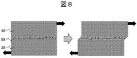
- Example 3 Ni is selected as the metal films 38 and 48 as in Example 1, and in addition to Ni, which is the same metal element, in the interface layer 58, Cu and S having low aggregation energy are mixed in the structural model FIG. It was constructed.
- shearing was applied in the same manner as in Example 1, it was found that slip deformation occurred and internal fracture was suppressed as shown in FIG. This is because, as in Example 1, the shear stress (155 MPa) at which shear occurs in the interface layer 58 during shearing is larger than the tensile stress (116 MPa) inside the Ni layers, which are the metal films 38 and 48. It is considered that the films 38 and 48 were hardly subjected to tensile deformation and were sheared at the interface layer 5.
- the elements constituting the interface layer 5 need not be composed only of elements completely different from those of the metal films 3 and 4 as shown in Examples 1 and 2, and elements having a small aggregation energy are pointed in the layer. It was found that if it exists, it has the same effect. As described above, in order to form an interface layer having a larger shear stress than the metal film, it can be achieved by increasing the content ratio of elements having a smaller aggregation energy than the metal film 3 or 4 in the interface layer.
- the manufacturing process of the laminate was carried out according to the above-mentioned flow. Specifically, first, as a pretreatment of the base material, a step of removing impurities by degreasing and pickling was performed. Further, in order to remove the oxide film of the base material and improve the adhesion of the plating film, strike plating of Ni was carried out.
- the thickness of each film was set to 500 nm, and the number of layers was 20 (the thickness of the entire plating film was 10 ⁇ m).
- the electrolysis conditions of the plating treatment step were carried out at a constant current using a Ni plate as the counter electrode.
- the treatment step for forming the interface layer 5 was performed by stopping the electrolysis, and the stop time was set to 30 seconds.
- a single-layer film was also produced instead of the film laminated portion.
- the prepared film was annealed. In the annealing treatment step, the annealing temperature was set to 300 ° C. and the holding time was set to 2 hours.
- Table 1 shows the composition of the plating solutions used in Examples 4 to 10 and Comparative Examples 2 to 4, the multi-layer / single-layer structure of the plating film, and the evaluation results of wear resistance.
- the component ratio was at%, Cu: 0.03 at%, Ni: 93.4 at%, P: 6.5 at%, S: 0.05 to 0. It was .07 at%.
- the content of the Cu component in the plating solution was 2.3 mg / L in terms of copper sulfate pentahydrate.
- Example 4 in which the interface layer 5 was formed, it was confirmed that the film did not peel off after the wear resistance test and the wear resistance was improved as compared with Comparative Examples 2 to 4. This is also correlated with the result of the simulation of Example 1, and it is considered that the wear resistance was improved in Example 4 because the internal growth of cracks generated in the film was suppressed.
- the orientation plane of the laminated body is preferably (100) oriented.
- FIG. 9 shows a cross-sectional SEM image of Example 5. As shown in this, it was confirmed that the produced film was formed from the film laminated portion. In addition, it was confirmed by SIMS analysis that more S than contained in the metal film was unevenly distributed at the interface of the plurality of layers. Moreover, when the concentration of the element contained in the film was analyzed by XRF, it was found that Ni: 93.36, P: 6.56, S: 0.07, Cu: 0.01 atomic%.
- FIG. 10 shows an atomic map of the interface analyzed by the atom probe.
- the main components of the interface are also Ni and P, but it was confirmed that Cu, which is a metal element having a small aggregation energy, is unevenly distributed at the 0.04 atomic% interface. At this time, it was confirmed that the interface layer was present at 10 nm or less. Further, regarding S, since it overlaps with the peak of Ni, its distribution could not be confirmed.
- Examples 11 to 14 In this example, Cu was selected as a metal element having a small aggregation energy, and the desirable amount of Cu added was examined. Further, the examination was carried out by the same method as the method shown in Examples 4 to 10 except that the plating solution was changed.
- Table 2 shows the results of Examples 11 to 14. At this time, regarding the wear resistance, each example was compared with the wear resistance of Example 11 in which 0.002 g / L of copper sulfate pentahydrate was added without adding saccharin as 100.
- the wear resistance of copper sulfate pentahydrate deteriorates when the concentration in the plating solution becomes larger than 0.02 g / L. Therefore, when Cu is selected as the metal element having a small aggregation energy, it is desirable that the concentration of copper sulfate pentahydrate in the plating solution is 0.02 g / L or less, particularly 0.01 g / L or less. It turned out.
- Examples 15 to 18, Comparative Example 5> an example of study in which the thicknesses of the metal films 3 and 4 are changed by using the plating solution of Example 12 is shown.
- the thickness of the metal film was adjusted to the thickness shown in Table 3 according to the electrolysis time. Other conditions are the same as in Examples 4 to 10.
- Table 3 shows the results of Examples 15 to 18 in which the thickness of the metal film was adjusted and Comparative Example 5 in which the treatment step for forming the interface layer 5 was not performed.
- Example 15 having a film laminated portion 12 having an interface layer 5 containing a large amount of metal elements having a small aggregation energy and Comparative Example 5 having a single-layer film 11 having no interface layer 5 introduced have resistance to resistance. It can be seen that the wear state of the surface after the wear test is different. As a result of observing the location where the surface peeling occurred, in Example 15 (FIG. 12), the peeled portion was uniformly extended laterally with respect to the sliding surface 70, and cracks did not grow so much in the film laminated portion 12. There was found.
Abstract
The purpose of the present invention is to provide: a laminate which does not contain hexavalent chromium and has excellent corrosion resistance and abrasion resistance; and a laminate manufacturing method. To achieve the purpose, a laminate according to the present invention is composed of a substrate and a film laminate part in which at least two metal films are laminated, and is characterized in that: an interfacial layer is provided between adjacent metal films; the film laminate part includes a first metal element containing, as a main component, at least one element among Ni, Cr, Co, and W, and a second metal element which is a metal element having smaller cohesive energy than the first metal element; and the content ratio of the second metal element contained in the interfacial layer is higher than the content ratio of the second metal element contained in the adjacent metal films.
Description
本発明は、基材上に複数層の皮膜が積層された積層体、金属めっき液、および積層体の製造方法に関するものである。
The present invention relates to a laminate in which a plurality of layers of coatings are laminated on a base material, a metal plating solution, and a method for producing the laminate.
近年、様々な機器において、以前よりも過酷環境下で使用される傾向が強まっている。例えば、洋上風力発電設備や、海水淡水化装置で用いられる配管やポンプ、融雪剤等が多量に散布される塩害が著しい地域における自動車や建設機器などが挙げられる。
In recent years, there is a growing tendency for various devices to be used in harsher environments than before. For example, offshore wind power generation equipment, pipes and pumps used in seawater desalination equipment, automobiles and construction equipment in areas where a large amount of snow melting agent is sprayed and salt damage is significant.
そのような機器に用いられている金属部品では、腐食や摩耗などの複合的要因により金属部品表面の劣化が進行し易く、機器のメンテナンス頻度の増大、さらには機器寿命の短縮を招くことが危惧される。
In metal parts used in such equipment, deterioration of the surface of the metal parts tends to progress due to multiple factors such as corrosion and wear, and there is a concern that the maintenance frequency of the equipment will increase and the life of the equipment will be shortened. Is done.
現状、前述した複合的要因による劣化が進行し易い金属部品には、耐食性および耐摩耗性に優れた6価クロムめっきによる表面処理がしばしば採用されている。
Currently, surface treatment with hexavalent chromium plating, which has excellent corrosion resistance and abrasion resistance, is often adopted for metal parts that are prone to deterioration due to the above-mentioned complex factors.
しかしながら、6価クロムは、REACH規則(Regulation concerning the Registration, Evaluation, Authorization and Restriction of Chemicals, establishing a European Chemicals Agency)等の環境規制や排水規制において環境高懸念物質として指定されており、その使用削減が世界的に望まれている。そのような背景を受け、6価クロムめっきに代替するめっき技術として様々な表面処理技術が提案されている。
However, hexavalent chromium is designated as a substance of very high concern in environmental regulations such as the REACH regulation (Regulation concerning the Registration, Evaluation, Authorization and Restriction of Chemicals, establishing a European Chemicals Agency), and its use is reduced. Is desired worldwide. Against this background, various surface treatment technologies have been proposed as plating technologies to replace hexavalent chromium plating.
例えば、特許文献1には、被めっき材の表面に複数のNi合金めっき皮膜が形成され、各層Ni合金めっき皮膜がP、B、Sから選ばれる元素を異なる濃度で含有し、かつ隣接するNi合金めっき皮膜の相互の電位的関係が、外側のNi合金めっき皮膜がその内側Niめっき皮膜より30 mV以上卑なる関係をもって設けられている多層Ni合金めっき皮膜等が開示されている。
For example, in Patent Document 1, a plurality of Ni alloy plating films are formed on the surface of the material to be plated, and each layer Ni alloy plating film contains an element selected from P, B, and S at different concentrations, and adjacent Ni. A multilayer Ni alloy plating film or the like in which an outer Ni alloy plating film is provided with a relationship of 30 mV or more lower than that of an inner Ni plating film is disclosed.
また、特許文献2には、硫黄を含有する複数層のニッケル合金皮膜が基材上に積層された皮膜積層体であって、各膜の前記Ni濃度の差が1質量%以内であり、膜間にS濃縮層を有するものが開示されている。また、S濃縮層の犠牲防食作用により孔食を膜厚水平方向に転換することが記載されている。
Further, Patent Document 2 describes a film laminate in which a plurality of layers of nickel alloy films containing sulfur are laminated on a base material, and the difference in Ni concentration between the films is within 1% by mass. Those having an S-concentrated layer between them are disclosed. Further, it is described that the pitting corrosion is converted in the horizontal direction of the film thickness by the sacrificial anticorrosion action of the S concentrated layer.
しかしながら、金属部品適用先の拡大、過酷化により、さらなる耐摩耗性、特に摺動摩耗、凝着摩耗等の改善が望まれる。
However, further improvement in wear resistance, especially sliding wear and adhesive wear, is desired due to the expansion of application destinations of metal parts and harsherness.
そこで本発明の目的は、6価クロムを用いず、耐食性および耐摩耗性に優れた積層体および積層体の製造方法を提供することを目的とする。
Therefore, an object of the present invention is to provide a laminate having excellent corrosion resistance and wear resistance without using hexavalent chromium, and a method for producing the laminate.
上記課題を解決するために、本発明に係る積層体は、基材と、金属皮膜を二層以上積層した皮膜積層部とよりなり、隣接する金属皮膜の間に界面層を有し、皮膜積層部はNi、Cr、Co、Wの少なくとも一つの元素を主成分である第一の金属元素と、前記第一の金属元素よりも凝集エネルギーが小さい金属元素である第二の金属元素とを含み、界面層に含まれる第二の金属元素の含有比は、隣接する金属皮膜に含まれる第二の金属元素の含有比よりも多いことを特徴とする。
In order to solve the above problems, the laminate according to the present invention comprises a base material and a film laminate portion in which two or more metal films are laminated, and has an interface layer between adjacent metal films, and the film laminates. The part contains a first metal element whose main component is at least one element of Ni, Cr, Co, and W, and a second metal element which is a metal element having a smaller aggregation energy than the first metal element. The content ratio of the second metal element contained in the interface layer is larger than the content ratio of the second metal element contained in the adjacent metal film.
本発明によれば、6価クロムを含まず、耐食性および耐摩耗性に優れた積層体を提供することができる。
According to the present invention, it is possible to provide a laminate that does not contain hexavalent chromium and has excellent corrosion resistance and wear resistance.
以下、本発明の実施形態として、皮膜構造体の一例について図面を用いて詳細に説明する。なお、本発明は、ここで取り上げた実施形態に限定されることはなく、発明の技術的思想を逸脱しない範囲で、公知技術と適宜組み合わせたり公知技術に基づいて改良したりすることが可能である。
Hereinafter, as an embodiment of the present invention, an example of the film structure will be described in detail with reference to the drawings. The present invention is not limited to the embodiments taken up here, and can be appropriately combined with a known technique or improved based on the known technique without departing from the technical idea of the invention. be.
(積層体)
図1は、本発明に係る積層体の一例を示す概略断面模式図である。図1に示したように、積層体は、基材2表面に皮膜積層部1が形成されている。ここでは、皮膜積層部1は、金属皮膜3と金属皮膜4との2層が積層されている。 (Laminated body)
FIG. 1 is a schematic cross-sectional schematic view showing an example of a laminated body according to the present invention. As shown in FIG. 1, in the laminated body, the film laminatedportion 1 is formed on the surface of the base material 2. Here, in the film laminated portion 1, two layers of a metal film 3 and a metal film 4 are laminated.
図1は、本発明に係る積層体の一例を示す概略断面模式図である。図1に示したように、積層体は、基材2表面に皮膜積層部1が形成されている。ここでは、皮膜積層部1は、金属皮膜3と金属皮膜4との2層が積層されている。 (Laminated body)
FIG. 1 is a schematic cross-sectional schematic view showing an example of a laminated body according to the present invention. As shown in FIG. 1, in the laminated body, the film laminated
基材2は、特に限定は無く、積層体の用途に応じて適宜選択できる。例えば、炭素鋼、低合金鋼、ステンレス鋼、銅、アルミニウム、それらの合金などを適宜利用できる。ただし、基材に凝集エネルギーの小さい金属元素が含まれること(例えば、後述するようにCuなどが基材中に含まれる場合)が好ましい。これは、積層体の製造プロセスにめっきプロセスを適用する場合には、基材からめっき液への凝集エネルギーの小さい金属元素の溶出があるため、めっき液中にあえて凝集エネルギーの小さい金属元素を添加剤として導入する必要がないためである。その場合、基材中に含有成分として凝集エネルギーの小さい金属元素が含まれていても良いし、基材が複数材料で構成(例えば、SUS基材の上に薄膜が形成)されているような場合であっても良く、含まれる形態に関しては特に制限されるものではない。
The base material 2 is not particularly limited and can be appropriately selected depending on the use of the laminated body. For example, carbon steel, low alloy steel, stainless steel, copper, aluminum, alloys thereof and the like can be appropriately used. However, it is preferable that the base material contains a metal element having a small aggregation energy (for example, when Cu or the like is contained in the base material as described later). This is because when the plating process is applied to the manufacturing process of the laminate, the metal element with low aggregation energy is eluted from the base material to the plating solution, so the metal element with low aggregation energy is intentionally added to the plating solution. This is because it is not necessary to introduce it as an agent. In that case, a metal element having a small aggregation energy may be contained in the base material as a contained component, or the base material is composed of a plurality of materials (for example, a thin film is formed on the SUS base material). This may be the case, and the included forms are not particularly limited.
本発明の積層体の特徴は、皮膜積層部1において、隣接する金属皮膜3と金属皮膜4との間(界面領域)に界面層5を備えることである。金属皮膜3,4は、Ni、Cr、Co、Wの少なくとも一つの元素(第一の金属元素)を主成分とする。界面層5は、金属皮膜3,4を構成する主成分(第一の金属元素)の凝集エネルギーよりも小さい凝集エネルギーの金属元素(第二の金属元素)の含有量が、隣接する金属皮膜3,4よりも多い。
A feature of the laminate of the present invention is that the film laminate 1 is provided with an interface layer 5 between the adjacent metal film 3 and the metal film 4 (interface region). The metal films 3 and 4 contain at least one element (first metal element) of Ni, Cr, Co, and W as a main component. The interface layer 5 has a metal element (second metal element) having an aggregation energy smaller than that of the main components (first metal element) constituting the metal films 3 and 4, and the content of the metal element (second metal element) is adjacent to the metal film 3. , More than 4.
なお、凝集エネルギーとは、凝集状態にある物質の原子を無限遠まで引き離すのに要するエネルギー(cohesive energy)である。今回、発明者らは、キッテル 固体物理学入門(上)第5版:丸善株式会社(1978年)(参考文献1)のp.70に掲載されている0K、1気圧の固体を基底状態にあるばらばらの中性原子にするのに要するエネルギー値を用いて検討を行った。尚、同文献p.28には、格子定数(最近接原子間距離)等が掲載されている。
The cohesive energy is the cohesive energy required to separate the atoms of a substance in a cohesive state to infinity. This time, the inventors of Kittel, Introduction to Solid Physics (1), 5th Edition: Maruzen Co., Ltd. (1978) (Reference 1), p. The study was carried out using the energy value required to make the solid at 0 K and 1 atm listed in No. 70 into the disjointed neutral atoms in the ground state. In addition, the same document p. In 28, the lattice constant (closest interatomic distance) and the like are posted.
金属皮膜3および4は、耐摩耗性の表面処理用途として用いられ、Ni、Cr、Co、Wから選ばれる少なくとも一つの元素(第一の金属元素)を主成分として含む金属で構成される。ここで、主成分とは50原子%以上含むことを指し、Crは有害な6価クロムを使用して作製したものは対象外とする。例えば、Ni、Cr、Co、Wの単金属や、Ni-Cr、Ni-Co、Ni-W、Cr-W、Co-Wなどの合金が挙げられる。ただし、耐摩耗性と耐食性の観点から、Niを含むことが望ましい。より望ましくは、Ni濃度が90原子%以上である。また、金属皮膜3および4に含まれる凝集エネルギーの小さい金属元素は、1原子%以内が好ましい。このようにすることで、皮膜積層部1の全体の特性を損なうことなく、耐摩耗性のみを向上することができる。
The metal films 3 and 4 are used for wear-resistant surface treatment and are composed of a metal containing at least one element (first metal element) selected from Ni, Cr, Co, and W as a main component. Here, the principal component means that it contains 50 atomic% or more, and Cr is excluded from those prepared using harmful hexavalent chromium. Examples thereof include single metals of Ni, Cr, Co and W, and alloys such as Ni—Cr, Ni—Co, Ni—W, Cr—W and CoW. However, it is desirable to contain Ni from the viewpoint of wear resistance and corrosion resistance. More preferably, the Ni concentration is 90 atomic% or more. Further, the metal element having a small aggregation energy contained in the metal films 3 and 4 is preferably 1 atomic% or less. By doing so, only the wear resistance can be improved without impairing the overall characteristics of the film laminated portion 1.
Niをベースとした金属皮膜3および4については、結晶質であることが好ましい。硬度を増大させることを目的に、さらにPもしくは/およびBを添加することで、Niの結晶粒径を微細にして金属皮膜を硬質化・高耐摩耗化することができる。また、この結晶粒径は小さい方が硬質化できるため好ましく、より具体的にはX線回折測定より算出した平均結晶粒径で4nm以上10nm以下が望ましく、6nm以上8nm以下とすることがより望ましい。これらの成分は、積層体に求められる特性によって適宜調整することができるが、高硬度化の観点からNiに対して3原子%以上含むことが好ましい。
The Ni-based metal films 3 and 4 are preferably crystalline. By further adding P or / and B for the purpose of increasing the hardness, the crystal grain size of Ni can be made finer to harden the metal film and make the metal film highly wear resistant. Further, it is preferable that the crystal particle size is smaller because it can be hardened. More specifically, the average crystal particle size calculated by X-ray diffraction measurement is preferably 4 nm or more and 10 nm or less, and more preferably 6 nm or more and 8 nm or less. .. These components can be appropriately adjusted according to the characteristics required for the laminate, but are preferably contained in an amount of 3 atomic% or more with respect to Ni from the viewpoint of increasing hardness.
また、同様に硬質化を目的として、同様に、酸化物(例えば、TiO2やAl2O3)の粒子や、炭化物(SiC、ダイヤモンド、B4C、WC,Cr3C2)の粒子を含む複合金属皮膜であっても良い。さらに、潤滑性を増大させることを目的として、例えば、BN、TiN、MoS2、ZnF、黒鉛などの粒子を含む複合金属皮膜としても良い。
Similarly, for the purpose of hardening, particles of oxides (for example, TiO 2 and Al 2 O 3 ) and particles of carbides (SiC, diamond, B 4 C, WC, Cr 3 C 2 ) are similarly used. It may be a composite metal film containing. Further, for the purpose of increasing lubricity, for example, a composite metal film containing particles such as BN, TiN, MoS 2 , ZnF, and graphite may be used.
なお、Niをベースとした金属皮膜3および4については、平滑面をだすことを目的として、Sを1原子%以内で含んでいることが好ましい。Sは、めっきで金属皮膜を形成する際に、Niの(111)面に選択的に吸着するため、配向面を(100)配向とすることができる。これにより、金属皮膜3および4の内部応力を低減することができ、クラック発生の抑制および耐摩耗性を向上することが期待できる。
The Ni-based metal films 3 and 4 preferably contain S within 1 atomic% for the purpose of producing a smooth surface. Since S is selectively adsorbed on the (111) plane of Ni when the metal film is formed by plating, the orientation plane can be oriented (100). As a result, the internal stresses of the metal films 3 and 4 can be reduced, and it can be expected that crack generation is suppressed and wear resistance is improved.
各金属皮膜3および4の厚みは、4nm以上1000nm以下とすることが好ましい。より好ましくは、8nm以上500nm以下である。4nmより小さくなってしまうと、層の厚みが平均結晶粒径以下となり、原理的に皮膜積層部1としての全体の特性に影響を及ぼしてしまうため好ましくない。また、1000nmより大きくなると、耐摩耗性を向上する効果を発現しにくくなってしまう。これにより、耐摩耗性を向上することができる。耐摩耗性に関しては、基本的には、金属皮膜3および4の厚みは薄ければ薄い方が良い。特に50nm以下が望ましいが、金属薄膜が薄い場合には目標となる被膜厚さまでの積層数が増加し、製造時間が長くなる。
The thickness of each of the metal films 3 and 4 is preferably 4 nm or more and 1000 nm or less. More preferably, it is 8 nm or more and 500 nm or less. If it is smaller than 4 nm, the thickness of the layer becomes equal to or less than the average crystal grain size, which in principle affects the overall characteristics of the film laminated portion 1, which is not preferable. Further, if it is larger than 1000 nm, it becomes difficult to exhibit the effect of improving the wear resistance. Thereby, the wear resistance can be improved. With regard to wear resistance, basically, the thinner the metal films 3 and 4, the better. In particular, 50 nm or less is desirable, but when the metal thin film is thin, the number of layers up to the target film thickness increases, and the production time becomes long.
さらに、各金属皮膜3および4の厚みは、図2に示すように同程度とするほか、適宜厚い金属皮膜、薄い金属皮膜を混在させてもよい。図3は、表面部で金属皮膜の厚みを小さくした例、図4は基材近傍領域で金属皮膜の厚みを小さくした例である。製造プロセス上の観点からは、図2のように同等の厚みとすることが望ましい。
Further, the thicknesses of the metal films 3 and 4 are about the same as shown in FIG. 2, and a thick metal film and a thin metal film may be mixed as appropriate. FIG. 3 shows an example in which the thickness of the metal film is reduced on the surface portion, and FIG. 4 is an example in which the thickness of the metal film is reduced in the region near the base material. From the viewpoint of the manufacturing process, it is desirable that the thickness is the same as shown in FIG.
界面層5は、前述の通り、金属皮膜3および4よりも凝集エネルギーの小さい金属元素(第二の金属元素)が多く含まれる層である。基本的には、界面層5の主成分は金属皮膜3もしくは4と同じ成分で構成することが製造上の観点から好ましい。この凝集エネルギーの小さい金属元素が多く含まれることは、界面層5の結合力を金属皮膜3および4よりも弱くすることを意味し、界面層5を弱くすることによって、摩耗時に表面および内部に発生するクラックの進展方向を積層体の積層方向に対して垂直方向(界面層の面内方向)に変化させる効果が得られる。このクラックの進展方向の変化によって、積層体の摩耗速度を低速化することができ、耐摩耗性が向上する。
As described above, the interface layer 5 is a layer containing a large amount of metal elements (second metal elements) having a smaller aggregation energy than the metal films 3 and 4. Basically, it is preferable from the viewpoint of manufacturing that the main component of the interface layer 5 is composed of the same components as the metal film 3 or 4. The inclusion of a large amount of metal elements having a small aggregation energy means that the bonding force of the interface layer 5 is weaker than that of the metal films 3 and 4, and by weakening the interface layer 5, the surface and the inside are worn. The effect of changing the growth direction of the generated cracks in the direction perpendicular to the stacking direction of the laminated body (in-plane direction of the interface layer) can be obtained. By changing the direction of growth of the cracks, the wear rate of the laminated body can be reduced, and the wear resistance is improved.
界面層5を構成する凝集エネルギーの小さい金属元素(第二の金属元素)は、製造上の形成し易さなどを考慮して様々な元素から選択することが可能である。金属皮膜3および4に主成分として含まれるNi、Cr、Co、W(第一の金属元素)のうち、Crの凝集エネルギーが最も小さく、395kJ/molである。Crよりも凝集エネルギーの小さい金属元素としては、アルカリ金属、アルカリ土類金属、Sc、Mn、Fe、Co、Cu、Ag、Au、Zn、Cd、Hg、Al、Ga、In、Tl、Ge、Sn、Pb、Sb、Bi、Pr、Nd、Sm、Eu、Tb、Dy、Ho、Er、Tm、Ybが挙げられる。
The metal element having a small aggregation energy (second metal element) constituting the interface layer 5 can be selected from various elements in consideration of ease of formation in manufacturing and the like. Among Ni, Cr, Co, and W (first metal element) contained in the metal films 3 and 4 as main components, the aggregation energy of Cr is the smallest, which is 395 kJ / mol. Metal elements having a lower aggregation energy than Cr include alkali metals, alkaline earth metals, Sc, Mn, Fe, Co, Cu, Ag, Au, Zn, Cd, Hg, Al, Ga, In, Tl, Ge, and so on. Examples thereof include Sn, Pb, Sb, Bi, Pr, Nd, Sm, Eu, Tb, Dy, Ho, Er, Tm and Yb.
金属皮膜3および4に主成分として含まれる上述の金属元素に対して、どの程度凝集エネルギーの小さい金属元素を使用するのが良いかは、選定した金属元素の添加量などの設計条件によって適切に選択することができる。
How low the cohesive energy should be used for the above-mentioned metal elements contained in the metal films 3 and 4 as the main components depends on the design conditions such as the amount of the selected metal element added. You can choose.
例えば、少量の添加で界面層5の結合力を弱くして、界面層5でのせん断を容易にする場合には、凝集エネルギーを極力小さい金属元素を選択することに加えて、金属皮膜3および4との格子ミスマッチが12%よりも大きくなる金属元素を選択することが望ましい。これにより、わずかな添加量で界面層5の結合力を弱くすることができる。例えば、Niを主成分として含む金属皮膜3および4の場合には、参考文献1のp.28に記載されている最近接原子間距離の値を用いて、2.79Å以上もしくは2.19Å以下である金属元素がこれに該当し、アルカリ金属、Beを除くアルカリ土類金属、Sc、Ag、Au、Cd、Hg、Al、In、Tl、Sn、Pb、Sb、Bi、Pr、Nd、Sm、Eu、Tb、Dy、Ho、Er、Tm、Ybが挙げられる。
For example, when the bonding force of the interface layer 5 is weakened by adding a small amount to facilitate shearing at the interface layer 5, in addition to selecting a metal element having a minimum aggregation energy, the metal film 3 and the metal film 3 and It is desirable to select a metal element whose lattice mismatch with 4 is greater than 12%. Thereby, the binding force of the interface layer 5 can be weakened with a small amount of addition. For example, in the case of the metal films 3 and 4 containing Ni as a main component, p. Using the value of the closest interatomic distance described in 28, metal elements of 2.79 Å or more or 2.19 Å or less correspond to this, and alkali metals, alkaline earth metals excluding Be, Sc, Ag. , Au, Cd, Hg, Al, In, Tl, Sn, Pb, Sb, Bi, Pr, Nd, Sm, Eu, Tb, Dy, Ho, Er, Tm, Yb.
一方で、例えば、添加量としてある程度量が導入できる場合には、界面層5の結合力は、金属皮膜3および4よりは弱くなくてはならないが、なるべくこれに近い方が良い。すなわち、凝集エネルギーは金属皮膜3および4に僅かに小さく、且つ格子ミスマッチも12%以内の金属元素を選択することが望ましい。例えば、Niを主成分として含む金属皮膜3および4の場合には、上述と同様に選択すると、Be、Mn、Fe、Co、Cu、Zn、Ga、Geが挙げられる。
On the other hand, for example, when a certain amount can be introduced as the addition amount, the bonding force of the interface layer 5 must be weaker than that of the metal films 3 and 4, but it is better to be as close to this as possible. That is, it is desirable to select a metal element whose aggregation energy is slightly smaller than that of the metal films 3 and 4 and whose lattice mismatch is within 12%. For example, in the case of the metal films 3 and 4 containing Ni as a main component, Be, Mn, Fe, Co, Cu, Zn, Ga, and Ge can be mentioned when selected in the same manner as described above.
また、めっきプロセスで皮膜積層部1を形成する場合には、凝集エネルギーの小さい金属元素の方が、金属皮膜3および4に主成分として含まれる金属元素よりも標準電極電位が高く貴な元素であることが望ましい。これによって、界面層5に含まれる凝集エネルギーの小さい金属元素を、金属皮膜3および4よりも多く含有させることが容易になる。また、界面層5を形成するために必要なめっき液への添加剤の量を少なくすることもできる。
Further, when the film laminated portion 1 is formed by the plating process, the metal element having a small aggregation energy has a higher standard electrode potential than the metal element contained as the main component in the metal films 3 and 4, and is a noble element. It is desirable to have. As a result, it becomes easy to contain a metal element having a small aggregation energy contained in the interface layer 5 in a larger amount than the metal films 3 and 4. Further, the amount of the additive to the plating solution required to form the interface layer 5 can be reduced.
これを考慮すれば、凝集エネルギーの小さい金属元素としては、例えば、Cu、Sn、Zn、Ag、Mn、Bi、In、Sbから選ばれる金属元素を含むことが望ましい。より好ましくはCuである。
Considering this, it is desirable that the metal element having a small aggregation energy contains, for example, a metal element selected from Cu, Sn, Zn, Ag, Mn, Bi, In, and Sb. More preferably, it is Cu.
界面層5には、凝集エネルギーの小さい金属元素の他に、半金属元素であるSがさらに含まれていても良い。Sがさらに含有することによって、せん断時に界面層5での滑りが生じやすくなるだけでなく、金属皮膜3および4が硬質化・平滑化され、皮膜積層部1の耐摩耗性が向上する。また、含有されるSによってめっき膜内部の引張応力を低減できるため、界面部で応力を緩和することが可能となる。これによりクラックの発生を抑制し、耐摩耗性が向上する。
The interface layer 5 may further contain S, which is a metalloid element, in addition to the metal element having a small aggregation energy. When S is further contained, not only slippage in the interface layer 5 is likely to occur during shearing, but also the metal films 3 and 4 are hardened and smoothed, and the wear resistance of the film laminated portion 1 is improved. Further, since the tensile stress inside the plating film can be reduced by the S contained, the stress can be relaxed at the interface portion. As a result, the occurrence of cracks is suppressed and the wear resistance is improved.
界面層5の厚みは、100nm以下で構成されることが望ましい。これ以上になると、金属皮膜3および4に加えて界面層5の特性が大きく皮膜積層部1の特性として影響するため好ましくない。界面層5の厚みは、特に10nm以下が好ましく、これにより皮膜積層部1にほとんど影響を与えずに耐摩耗性のみを向上することが可能となる。
It is desirable that the thickness of the interface layer 5 is 100 nm or less. If it is more than this, the characteristics of the interface layer 5 in addition to the metal films 3 and 4 are large and affect the characteristics of the film laminated portion 1, which is not preferable. The thickness of the interface layer 5 is particularly preferably 10 nm or less, which makes it possible to improve only the wear resistance with almost no effect on the film laminated portion 1.
(積層体を製造するためのめっき液)
本発明に係る積層体を製造するためのめっき液について説明する。本発明の積層体の製造方法(皮膜積層部の製膜方法)としては、湿式処理(例えば、電気めっき)や乾式処理(例えば、スパッタリング)などの処理方法を利用できるが、量産性の観点からは、電気めっきが好ましい形態である。 (Plating liquid for manufacturing laminates)
The plating solution for producing the laminate according to the present invention will be described. As a method for producing a laminated body of the present invention (a method for forming a film of a film laminated portion), a treatment method such as a wet treatment (for example, electroplating) or a dry treatment (for example, sputtering) can be used, but from the viewpoint of mass productivity. Is a preferred form of electroplating.
皮膜積層部1を製膜するための電気めっき液は、Ni、Cr、Co、Wから選ばれる少なくとも一つ以上の金属塩が主成分として含まれ、且つこれらの金属元素よりも凝集エネルギーの小さい金属元素を含む化合物が含まれる。
The electroplating liquid for forming the film laminated portion 1 contains at least one or more metal salts selected from Ni, Cr, Co, and W as main components, and has a smaller aggregation energy than these metal elements. Contains compounds containing metal elements.
主成分である、金属皮膜3および4を形成するためのめっき液中に含有される金属塩としては、6価クロムを含まないこと以外に限定は無く、硫酸化物、塩化物など一般的なものが使用できる。例えば、硫酸ニッケル、塩化ニッケル、硫酸銅、塩化銅、硫酸コバルト、塩化コバルト、塩化タングステンなどが挙げられ、これらを複合的に用いることもできる。
The metal salt contained in the plating solution for forming the metal films 3 and 4, which is the main component, is not limited except that it does not contain hexavalent chromium, and is general such as sulfated and chloride. Can be used. For example, nickel sulfate, nickel chloride, copper sulfate, copper chloride, cobalt sulfate, cobalt chloride, tungsten chloride and the like can be mentioned, and these can be used in combination.
界面層5を形成するための凝集エネルギーの小さい金属元物は、例えば、アルカリ金属、アルカリ土類金属、Sc、Mn、Fe、Co、Cu、Ag、Au、Zn、Cd、Hg、Al、Ga、In、Tl、Ge、Sn、Pb、Sb、Bi、Pr、Nd、Sm、Eu、Tb、Dy、Ho、Er、Tm、Ybが使用できる。
Metal elements having a small aggregation energy for forming the interface layer 5 include, for example, alkali metals, alkaline earth metals, Sc, Mn, Fe, Co, Cu, Ag, Au, Zn, Cd, Hg, Al, Ga. , In, Tl, Ge, Sn, Pb, Sb, Bi, Pr, Nd, Sm, Eu, Tb, Dy, Ho, Er, Tm, Yb can be used.
めっき液中に含まれる凝集エネルギーの小さい金属元素を含む化合物の形態としては、特に限定はなく、その金属元素を含む金属塩や、有機金属化合物などを使用できる。例えば、塩化物や硫化物、有機金属化合物がそれに該当する。
The form of the compound containing a metal element having a small aggregation energy contained in the plating solution is not particularly limited, and a metal salt containing the metal element, an organic metal compound, or the like can be used. For example, chlorides, sulfides, and organometallic compounds fall under this category.
なお、これらをめっき液に添加することで、これらの凝集エネルギーの小さい金属元素は、界面層5のみではなく、金属皮膜3および4にも微量含まれる。
By adding these to the plating solution, these metal elements having a small aggregation energy are contained not only in the interface layer 5 but also in the metal films 3 and 4 in a trace amount.
金属皮膜3および4に主成分として含まれる上述の金属元素に対して、どの程度凝集エネルギーの小さい金属元素を使用するのが良いかは、選定した金属元素の添加量などの設計条件によってめっき液の添加量も適切に選択することができる。
How low the cohesive energy should be used for the above-mentioned metal elements contained in the metal films 3 and 4 as the main component depends on the design conditions such as the amount of the selected metal element added. The amount of the addition can also be appropriately selected.
例えば、少量の添加で界面層5の結合力を弱くして、界面層5でのせん断を容易にする場合には、凝集エネルギーを極力小さい金属元素を選択してめっき液に加えることに加えて、金属皮膜3および4との格子ミスマッチが12%よりも大きくなる金属元素を選択してめっき液に加えることが望ましい。例えば、Niを主成分として含む金属皮膜3および4の場合には、アルカリ金属、Beを除くアルカリ土類金属、Sc、Ag、Au、Cd、Hg、Al、In、Tl、Sn、Pb、Sb、Bi、Pr、Nd、Sm、Eu、Tb、Dy、Ho、Er、Tm、Ybを含む塩化物や硫化物、有機金属化合物が挙げられる。
For example, when the bonding force of the interface layer 5 is weakened by adding a small amount to facilitate shearing at the interface layer 5, in addition to selecting a metal element having the smallest possible aggregation energy and adding it to the plating solution. It is desirable to select a metal element having a lattice mismatch with the metal films 3 and 4 larger than 12% and add it to the plating solution. For example, in the case of metal films 3 and 4 containing Ni as a main component, alkali metals, alkaline earth metals excluding Be, Sc, Ag, Au, Cd, Hg, Al, In, Tl, Sn, Pb, Sb , Bi, Pr, Nd, Sm, Eu, Tb, Dy, Ho, Er, Tm, Yb-containing chlorides and sulfides, and organic metal compounds.
一方で、例えば、添加量としてある程度量が導入できる場合には、界面層5の結合力は、金属皮膜3および4よりは弱くなくてはならないが、なるべくこれに近い方が良い。すなわち、凝集エネルギーは金属皮膜3および4に僅かに小さく、且つ格子ミスマッチも12%以内の金属元素を選択してめっき液へ加えることが望ましい。例えば、Niを主成分として含む金属皮膜3および4の場合には、Be、Mn、Fe、Co、Cu、Zn、Ga、Geを含む塩化物や硫化物、有機金属化合物を添加することが好ましい。
On the other hand, for example, when a certain amount can be introduced as the addition amount, the bonding force of the interface layer 5 must be weaker than that of the metal films 3 and 4, but it is better to be as close to this as possible. That is, it is desirable to select a metal element having a cohesive energy slightly smaller than that of the metal films 3 and 4 and having a lattice mismatch of 12% or less and adding it to the plating solution. For example, in the case of the metal films 3 and 4 containing Ni as a main component, it is preferable to add chlorides, sulfides and organic metal compounds containing Be, Mn, Fe, Co, Cu, Zn, Ga and Ge. ..
ただし、めっき法にて本願発明の積層体を構成する場合には、めっき液に添加した量がそのまま金属皮膜3および4や界面層5になるわけではないため、適宜成分量を調整することができる。例えば、めっきの主成分としてNi、凝集エネルギーの小さい金属元素としてCuを使用する場合、Cuのめっき液への添加量はNi塩の3/100000以下でよい。
However, when the laminate of the present invention is formed by the plating method, the amount added to the plating solution does not directly become the metal films 3 and 4, or the interface layer 5, so the amount of the components may be adjusted as appropriate. can. For example, when Ni is used as the main component of the plating and Cu is used as the metal element having a small aggregation energy, the amount of Cu added to the plating solution may be 3/4100,000 or less of the Ni salt.
また、めっきプロセスで皮膜積層部1を形成する場合には、凝集エネルギーの小さい金属元素の方が、金属皮膜3および4に主成分として含まれる金属元素よりも貴であることが望ましい。これを考慮すれば、めっきの主成分がNiの場合、凝集エネルギーの小さい金属元素としては、例えば、Cu、Sn、Zn、Mn、Bi、Inから選ばれることが望ましい。より好ましくは、Cuである。
Further, when the film laminated portion 1 is formed by the plating process, it is desirable that the metal element having a small aggregation energy is noble than the metal element contained as the main component in the metal films 3 and 4. Considering this, when the main component of the plating is Ni, it is desirable that the metal element having a small aggregation energy is selected from, for example, Cu, Sn, Zn, Mn, Bi, and In. More preferably, it is Cu.
また、めっき液には、一般的なめっき成分として、還元剤、錯化剤、pH調整剤、支持塩やその他の添加剤を含むことも可能である。例えば、金属皮膜3および4の主成分がNiの場合、硬度を増加させることを目的として、金属皮膜にPもしくは/およびBの成分を含有させることが望ましい。この場合、主成分としては、例えば、リン化合物としてホスホン酸、ホウ素化合物としてホウ酸などを使用して含有させることができる。
The plating solution can also contain a reducing agent, a complexing agent, a pH adjuster, a supporting salt and other additives as general plating components. For example, when the main components of the metal films 3 and 4 are Ni, it is desirable that the metal film contains P or / and B components for the purpose of increasing the hardness. In this case, as the main component, for example, phosphonic acid as a phosphorus compound, boric acid as a boron compound, or the like can be used and contained.
また、同様に添加剤による硬質化を目的として、めっき液中に酸化物(例えば、TiO2やAl2O3)の粒子や、炭化物(SiC、ダイヤモンド、B4C、WC,Cr3C2)の粒子を含有・分散させることも可能である。また、潤滑性を増大させることを目的として、BN、TiN、MoS2、ZnF、黒鉛などの粒子を同様にめっき液中に含有・分散させることも可能である。
Further, for the purpose of hardening due Similarly additive oxide in the plating solution (e.g., TiO 2 and Al 2 O 3) and particles of carbide (SiC, diamond, B 4 C, WC, Cr 3 C 2 ) Can be contained and dispersed. Further, for the purpose of increasing the lubricity , particles such as BN, TiN, MoS 2 , ZnF, and graphite can be similarly contained and dispersed in the plating solution.
界面層5のせん断時のすべりをよくすること、および金属皮膜3および4の硬質化・平滑化を目的として、凝集エネルギーの小さい金属元素の他に、半金属元素である硫黄を含む硫黄含有有機化合物がめっき液中に含まれることが望ましい。硫黄含有有機化合物としては、公知の光沢剤であるサッカリン、ラウリル硫酸ナトリウム、アリルスルホン酸、チオ尿素などを使用できる。これらの添加剤は、金属皮膜3および4の表面に吸着し易く、界面層5を容易に形成することができる。
Sulfur-containing organics containing sulfur, which is a metalloid element, in addition to metal elements with low aggregation energy, for the purpose of improving the slip of the interface layer 5 during shearing and hardening / smoothing the metal films 3 and 4. It is desirable that the compound is contained in the plating solution. As the sulfur-containing organic compound, known brighteners such as saccharin, sodium lauryl sulfate, allylsulfonic acid, and thiourea can be used. These additives are easily adsorbed on the surfaces of the metal films 3 and 4, and the interface layer 5 can be easily formed.
なお、電気めっき液の各種成分濃度は適宜調整することができる。
The concentration of various components of the electroplating solution can be adjusted as appropriate.
(積層体の製造方法)
本発明に係る積層体の製造方法について説明する。上述の通り、本発明の積層体の製造方法(皮膜積層部の製膜方法)としては、湿式処理(例えば、電気めっき)や乾式処理(例えば、スパッタリング)などの処理方法を利用できるが、量産性の観点から電気めっきが好ましい形態であるため、以下に電気めっきで積層体を製造する方法について記載する。
本発明に係る積層体の製造方法の一例である電気めっきプロセスを以下に示す。
1.金属皮膜3のめっき処理ステップ
2.界面層5を形成するための処理ステップ
3.金属皮膜4のめっき処理ステップ
4.水洗ステップ
5.乾燥ステップ
6.アニール処理ステップ。 (Manufacturing method of laminated body)
A method for producing a laminate according to the present invention will be described. As described above, as the method for producing the laminate of the present invention (method for forming the film-laminated portion), a treatment method such as wet treatment (for example, electroplating) or dry treatment (for example, sputtering) can be used, but mass production is possible. Since electroplating is a preferable form from the viewpoint of properties, a method for producing a laminate by electroplating will be described below.
The electroplating process, which is an example of the method for producing a laminate according to the present invention, is shown below.
1. 1. Plating process step ofmetal film 3 2. Processing step for forming the interface layer 5. Plating step of metal film 4 4. Washing step 5. Drying step 6. Annealing step.
本発明に係る積層体の製造方法について説明する。上述の通り、本発明の積層体の製造方法(皮膜積層部の製膜方法)としては、湿式処理(例えば、電気めっき)や乾式処理(例えば、スパッタリング)などの処理方法を利用できるが、量産性の観点から電気めっきが好ましい形態であるため、以下に電気めっきで積層体を製造する方法について記載する。
本発明に係る積層体の製造方法の一例である電気めっきプロセスを以下に示す。
1.金属皮膜3のめっき処理ステップ
2.界面層5を形成するための処理ステップ
3.金属皮膜4のめっき処理ステップ
4.水洗ステップ
5.乾燥ステップ
6.アニール処理ステップ。 (Manufacturing method of laminated body)
A method for producing a laminate according to the present invention will be described. As described above, as the method for producing the laminate of the present invention (method for forming the film-laminated portion), a treatment method such as wet treatment (for example, electroplating) or dry treatment (for example, sputtering) can be used, but mass production is possible. Since electroplating is a preferable form from the viewpoint of properties, a method for producing a laminate by electroplating will be described below.
The electroplating process, which is an example of the method for producing a laminate according to the present invention, is shown below.
1. 1. Plating process step of
なお、2層の金属皮膜3,4を積層した皮膜積層部1について記載したが、積層体が適用される部品や製品に要求される耐食性、耐摩耗性、寿命などの仕様に応じて、金属皮膜の層数は適宜設定することができる。その場合、皮膜積層部1の金属皮膜3および4の層数に応じて、上記1~3のステップを適宜繰り返し行えばよい。
Although the film laminated portion 1 in which two layers of metal films 3 and 4 are laminated has been described, the metal is required according to the specifications such as corrosion resistance, abrasion resistance, and life required for the parts and products to which the laminated body is applied. The number of film layers can be set as appropriate. In that case, the above steps 1 to 3 may be repeated as appropriate according to the number of layers of the metal films 3 and 4 of the film laminated portion 1.
本発明の積層体の皮膜積層部1において、優れた耐摩耗性を発現させるためには、上記プロセスにおける2.界面層5を形成するためのステップと6.アニール処理ステップとが重要となる。
In order to develop excellent wear resistance in the film laminated portion 1 of the laminated body of the present invention, 2. Steps for forming the interface layer 5 and 6. The annealing step is important.
界面層5を形成するためのステップは、めっき処理と異なる条件により界面層を形成できれば適宜選択可能である。例えば、めっき処理の停止条件下で、金属皮膜に吸着する化合物(界面層前駆体物質)をめっき液に添加することで、めっき処理の停止時間を界面層5を形成するステップとすることができる。具体的には、めっき液に浸漬したままで、充分なめっき処理の停止時間(たとえば30秒間以上)とすることにより、金属皮膜3の表面に界面層5を形成する前駆体物質が吸着し、後に3.金属皮膜4のめっき処理ステップと同時に界面層5が形成できる。また、この界面層5の形成処理であるめっき処理後の停止と金属皮膜4のめっき処理ステップの間には水洗を入れないことが特徴である。水洗を入れると、表面に吸着した界面層5を形成するための吸着物が流れてしまい、界面層5を形成することができない。
The step for forming the interface layer 5 can be appropriately selected as long as the interface layer can be formed under conditions different from those of the plating treatment. For example, by adding a compound (interfacial layer precursor substance) adsorbed on the metal film to the plating solution under the condition of stopping the plating treatment, the stopping time of the plating treatment can be set as a step of forming the interface layer 5. .. Specifically, the precursor substance forming the interface layer 5 is adsorbed on the surface of the metal film 3 by setting a sufficient stop time (for example, 30 seconds or more) for the plating process while being immersed in the plating solution. Later 3. The interface layer 5 can be formed at the same time as the plating treatment step of the metal film 4. Further, it is characterized in that no water washing is performed between the stop after the plating treatment, which is the formation treatment of the interface layer 5, and the plating treatment step of the metal film 4. When washed with water, the adsorbent for forming the interface layer 5 adsorbed on the surface flows, and the interface layer 5 cannot be formed.
アニール処理ステップでは、アニール温度を300℃以下とすることが好ましい。これは、本発明者等が鋭意研究した結果から得られた知見である。アニール温度を300℃以下とすることにより、ニッケル合金皮膜の平均結晶粒径を8 nm以下に維持することができる。アニール温度が300℃超になると、ニッケル合金皮膜の結晶粒が粗大化し易くなって皮膜積層部1の硬度が低下する。アニール処理時間は、特に限定は無いが、例えば1時間以上行うと良好である。
In the annealing treatment step, the annealing temperature is preferably 300 ° C. or lower. This is a finding obtained from the results of diligent research by the present inventors. By setting the annealing temperature to 300 ° C. or lower, the average crystal grain size of the nickel alloy film can be maintained to 8 nm or less. When the annealing temperature exceeds 300 ° C., the crystal grains of the nickel alloy film tend to be coarsened, and the hardness of the film laminated portion 1 decreases. The annealing treatment time is not particularly limited, but it is good if it is performed for, for example, 1 hour or more.
なお、1.金属皮膜3のめっき処理ステップおよび3.金属皮膜4のめっき処理ステップの電解条件は、所望の皮膜厚さに応じて電流密度や処理時間を適宜調整すればよく、各皮膜の厚さを統一する観点から、同じ条件とすることが好ましい。
Note that 1. Plating step of metal film 3 and 3. The electrolytic conditions of the plating treatment step of the metal film 4 may be appropriately adjusted in current density and treatment time according to a desired film thickness, and are preferably the same conditions from the viewpoint of unifying the thickness of each film. ..
また、必要に応じて、1.金属皮膜3のめっき処理ステップの前に、基材2の前処理として、脱脂、酸洗などの不純物除去ステップを行ってもよい。さらに、皮膜積層部1の密着性を改善するための密着相を形成ステップ(例えば、ストライクめっきなど)として行ってもよい。
Also, if necessary, 1. Prior to the plating treatment step of the metal film 3, an impurity removal step such as degreasing or pickling may be performed as a pretreatment of the base material 2. Further, an adhesion phase for improving the adhesion of the film laminated portion 1 may be performed as a forming step (for example, strike plating).
以上説明したように、本発明の積層体の製造方法は、1つのめっき浴を用いて、同じ電解条件にて金属皮膜を複数層形成するため、簡便で生産性が高い(すなわち、低コストである)という利点がある。
As described above, the method for producing a laminate of the present invention is simple and highly productive (that is, at low cost) because a plurality of metal films are formed under the same electrolytic conditions using one plating bath. There is an advantage.
本発明において、基材2の形状(すなわち、積層体の形状)は特に限定されず、任意の形状(例えば、塊、平板、曲板、円筒、角柱)の部品に適用できる。ただし、電気めっきにより皮膜を形成する場合は、部品形状(基材2の形状)によっては電流分布の影響で場所により皮膜厚さがばらつく可能性がある。そこで、事前に電流分布の影響を解析および実測により測定し、必要に応じて、被めっき物と対極との間に遮蔽板等を設置するなどして、めっき箇所による皮膜厚さのばらつきを抑制できる条件下で実施することが好ましい。
In the present invention, the shape of the base material 2 (that is, the shape of the laminated body) is not particularly limited, and can be applied to parts having any shape (for example, a lump, a flat plate, a curved plate, a cylinder, a prism). However, when the film is formed by electroplating, the film thickness may vary depending on the location due to the influence of the current distribution depending on the shape of the part (shape of the base material 2). Therefore, the influence of the current distribution is measured in advance by analysis and actual measurement, and if necessary, a shielding plate or the like is installed between the object to be plated and the counter electrode to suppress variations in film thickness depending on the plating location. It is preferable to carry out under possible conditions.
以下、実施例を用いて更に詳細に説明する。ただし、本発明は、ここで取り上げた実施例の記載に限定されることはなく、適宜組み合わせてもよい。
Hereinafter, a more detailed description will be given using examples. However, the present invention is not limited to the description of the examples taken up here, and may be combined as appropriate.
(界面モデルの分子動力学シミュレーション)
<実施例1、比較例1> (Molecular dynamics simulation of interface model)
<Example 1, Comparative Example 1>
<実施例1、比較例1> (Molecular dynamics simulation of interface model)
<Example 1, Comparative Example 1>
本発明の効果を示すため、構造モデルに対する分子動力学シミュレーションを行い、凝集エネルギーの相対関係による被膜積層部の変形の挙動を評価した。本実施例では、例えばR. Car and M. Parrinello, Phys. Rev. Lett., 50, 2471. (1985).(参考文献2)に示されているような手法を用いて検討した。図5~図8に示すように、金属皮膜の種類を変えた積層体の金属皮膜3および4にせん断力を加え、そのときの破壊部位や変形を検討した。応力に関しては、例えば、S. C. Chowdhury, B. Z. G. Haque and J. W. Gilespie, J. Mater. Sci., 51, 10139 (参考文献3)には、分子動力学法を用いてビリアルの式から応力を計算する手法が掲載されている。発明者らは、参考文献3の式(1)に掲載されているように、分子動力学シミュレーションを用いてビリアルの式から応力を算出した。
In order to show the effect of the present invention, a molecular dynamics simulation was performed on the structural model, and the deformation behavior of the coating laminated portion due to the relative relationship of aggregation energy was evaluated. In this example, for example, a method as shown in R. Car and M. Parrinello, Phys. Rev. Lett., 50, 2471. (1985). (Reference 2) was used. As shown in FIGS. 5 to 8, a shearing force was applied to the metal films 3 and 4 of the laminated body in which the type of the metal film was changed, and the fracture site and deformation at that time were examined. Regarding stress, for example, S.C.Chowdhury, B.Z.G.Haque and J.W.Gilespie, J.Matter.Sci., 51,10139 (Reference 3) uses the molecular dynamics method. A method for calculating stress from the Virial equation is posted. The inventors calculated the stress from Virial's equation using a molecular dynamics simulation as described in Equation (1) of Reference 3.
実施例1では、金属皮膜35および45としてNi(凝集エネルギー 428kJ/mol)を選択し、界面層55の凝集エネルギーの小さい金属元素としてCu(凝集エネルギー 336kJ/mol)を選択し、図5に示すような構造モデルを構築した。この構造モデルに対し、摩耗試験時に加わるせん断を変形速度10m/sの速度で与えた。
In Example 1, Ni (aggregation energy 428 kJ / mol) was selected as the metal films 35 and 45, and Cu (aggregation energy 336 kJ / mol) was selected as the metal element having a small aggregation energy in the interface layer 55, and is shown in FIG. A structural model like this was constructed. Shear applied during the wear test was applied to this structural model at a deformation rate of 10 m / s.
その結果、Cu層およびCuとNiの界面部分がすべり変形を生じ、内部破壊が抑制されることが判明した。これは、せん断時に、界面層55でせん断が発生するせん断応力(168MPa)の方が、金属皮膜35、45を構成するNi層の内部の引張応力(98.7MPa)よりも大きいために、金属皮膜35、45では引張変形がほとんど起こらず、界面層55でせん断されたためと考えられる。すなわち、凝集エネルギーが小さい金属元素が界面層55に存在する場合には、摩耗試験時に、内部にクラックが進展せずに、界面層55に沿ってせん断・進展することが推察される。
As a result, it was found that the Cu layer and the interface between Cu and Ni undergo slip deformation and internal fracture is suppressed. This is because the shear stress (168 MPa) at which shear occurs in the interface layer 55 during shearing is larger than the tensile stress (98.7 MPa) inside the Ni layers constituting the metal films 35 and 45. It is considered that the films 35 and 45 were hardly subjected to tensile deformation and were sheared at the interface layer 55. That is, when a metal element having a small aggregation energy is present in the interface layer 55, it is presumed that the crack does not grow inside but shears and grows along the interface layer 55 during the wear test.
一方で、図6には比較例1を示す。比較例1では、金属皮膜36、46として、実施例1と同様にNiを選択し、界面層56にはNiよりも凝集エネルギーの大きい金属元素であるW(凝集エネルギー 859kJ・mol)を選択した。実施例1と同様に、図6に示すような構造モデルを構築し、構造モデルに対し、同様にせん断を変形速度10m/sの速度で与えた。
On the other hand, FIG. 6 shows Comparative Example 1. In Comparative Example 1, Ni was selected as the metal films 36 and 46 in the same manner as in Example 1, and W (aggregation energy 859 kJ · mol), which is a metal element having a larger aggregation energy than Ni, was selected for the interface layer 56. .. Similar to Example 1, a structural model as shown in FIG. 6 was constructed, and shear was similarly applied to the structural model at a deformation speed of 10 m / s.
その結果、Niよりなる金属皮膜36にクラックが発生し、さらに発生したクラックは界面層56を突き抜けて、金属皮膜46へ進展することが判明した。これは、せん断時に発生する金属皮膜36および46であるNi層内部の引張応力(216MPa)が、界面でのせん断応力(187MPa)よりも大きいために、せん断変形よりも内部破壊が優先的に生じた結果であると考えられる。すなわち、凝集エネルギーが大きい金属元素を用いた界面層56では、摩耗試験時に、クラックが界面層56を突き抜けて内部に進展するため、耐摩耗性の向上は見込めないことが判明した。
As a result, it was found that cracks were generated in the metal film 36 made of Ni, and the further cracks penetrated the interface layer 56 and propagated to the metal film 46. This is because the tensile stress (216 MPa) inside the Ni layer, which is the metal films 36 and 46 generated during shearing, is larger than the shear stress (187 MPa) at the interface, so that internal fracture occurs preferentially over shear deformation. It is considered that this is the result. That is, it was found that in the interface layer 56 using a metal element having a large cohesive energy, cracks penetrate the interface layer 56 and propagate inward during the wear test, so that improvement in wear resistance cannot be expected.
以上の結果より、隣接する金属皮膜3および4の凝集エネルギーよりも、凝集エネルギーの小さい金属元素が界面層5に存在するとき、金属皮膜の摩耗試験時にクラックの内部進展が抑制され、耐摩耗性が向上することが分かった。
From the above results, when a metal element having an agglomeration energy smaller than that of the adjacent metal films 3 and 4 is present in the interface layer 5, the internal growth of cracks is suppressed during the wear test of the metal film, and the abrasion resistance is reduced. Was found to improve.
なお、界面層5がなく、実施例1、比較例1と同様の厚みの皮膜(比較例2)の場合に関しては計算していないが、せん断されるような界面層5が存在しないので、比較例1と同様の結果になると推察される。
It should be noted that the case where there is no interface layer 5 and the film has the same thickness as that of Example 1 and Comparative Example 1 (Comparative Example 2) has not been calculated, but since there is no interface layer 5 to be sheared, a comparison is made. It is presumed that the result will be the same as in Example 1.
また、本実施例1では、界面層5に適用する凝集エネルギーの小さい金属元素としてCuを選択したが、同様の効果の得られる界面層5の他の例について検討した。Cu以外の金属元素が存在する場合であっても、界面層5の凝集エネルギーが、金属皮膜3および4の凝集エネルギーよりも小さい場合には、原理的に同様の現象が発生すると考えられる。
Further, in this Example 1, Cu was selected as the metal element having a small aggregation energy applied to the interface layer 5, but another example of the interface layer 5 in which the same effect can be obtained was examined. Even when a metal element other than Cu is present, if the aggregation energy of the interface layer 5 is smaller than the aggregation energy of the metal films 3 and 4, it is considered that the same phenomenon occurs in principle.
すなわち、界面層5に存在する金属元素は、Cuに限るところではなく、凝集エネルギーの小さい金属元素であれば制限されるところではない。したがって、本検討の結果はCu以外でも例えば、アルカリ金属、アルカリ土類金属、Sc、Mn、Fe、Co、Ag、Au、Zn、Cd、Hg、Al、Ga、In、Tl、Ge、Sn、Pb、Sb、Bi、Pr、Nd、Sm、Eu、Tb、Dy、Ho、Er、Tm、Ybなどの金属元素でも成立すると考えられる。
That is, the metal element existing in the interface layer 5 is not limited to Cu, and is not limited as long as it is a metal element having a small aggregation energy. Therefore, the results of this study include, for example, alkali metals, alkaline earth metals, Sc, Mn, Fe, Co, Ag, Au, Zn, Cd, Hg, Al, Ga, In, Tl, Ge, Sn, other than Cu. It is considered that metal elements such as Pb, Sb, Bi, Pr, Nd, Sm, Eu, Tb, Dy, Ho, Er, Tm, and Yb also hold.
<実施例2>
実施例1、比較例1では、界面層5に適用する金属元素として金属単体を検討した。さらに、本実施例2として、界面層5に複数の元素が混在する場合について検討を行った。 <Example 2>
In Example 1 and Comparative Example 1, a single metal was examined as a metal element applied to theinterface layer 5. Further, as Example 2, a case where a plurality of elements are mixed in the interface layer 5 was examined.
実施例1、比較例1では、界面層5に適用する金属元素として金属単体を検討した。さらに、本実施例2として、界面層5に複数の元素が混在する場合について検討を行った。 <Example 2>
In Example 1 and Comparative Example 1, a single metal was examined as a metal element applied to the
図7に示すように、実施例1と同様に金属皮膜37および47としてNiを選択し、界面層57に凝集エネルギーの小さい金属元素であるCuに加えて、半金属元素であるS(凝集エネルギー 275kJ/mol)が混在して層を形成する構造モデルを構築した。ここで、Sを選定した理由は、凝集エネルギーが小さいことに加えて、めっきプロセスを想定した場合に、S含有化合物が光沢剤として広く一般的に添加され、めっき液やめっき膜に導入しやすく、耐摩耗性以外の観点で添加が必須となる可能性を持つ元素なためである。
As shown in FIG. 7, Ni was selected as the metal films 37 and 47 as in Example 1, and in addition to Cu, which is a metal element having a small aggregation energy, S (aggregation energy), which is a metalloid element, was added to the interface layer 57. A structural model was constructed in which 275 kJ / mol) was mixed to form a layer. Here, the reason why S is selected is that, in addition to the small aggregation energy, the S-containing compound is widely and generally added as a brightener when assuming a plating process, and it is easy to introduce it into a plating solution or a plating film. This is because it is an element that may be indispensable to be added from the viewpoints other than wear resistance.
実施例1同様にせん断を与えたところ、図7右図に示すように界面層57ですべり変形が生じて内部破壊が抑制されることが判明した。これは、実施例1同様に、せん断時に界面層57でせん断が発生するせん断応力(172MPa)の方が金属皮膜37および47であるNi層内部の引張応力(57.3MPa)よりも大きいために、金属皮膜37および47では引張変形がほとんど起こらず、界面層57でせん断されたためと考えられる。
When shearing was applied in the same manner as in Example 1, it was found that slip deformation occurred in the interface layer 57 as shown in the right figure of FIG. 7, and internal fracture was suppressed. This is because, as in Example 1, the shear stress (172 MPa) at which shear occurs in the interface layer 57 during shearing is larger than the tensile stress (57.3 MPa) inside the Ni layer, which is the metal films 37 and 47. It is considered that the metal films 37 and 47 were hardly subjected to tensile deformation and were sheared at the interface layer 57.
したがって、凝集エネルギーの小さい金属元素に加えて、半金属元素であるSが混在するような場合でも同様の効果が得られることが判明した。
Therefore, it was found that the same effect can be obtained even when S, which is a metalloid element, is mixed in addition to the metal element having a small aggregation energy.
<実施例3>
実施例3では、実施例1同様に金属皮膜38および48としてNiを選択し、界面層58に同じ金属元素であるNiに加えて、凝集エネルギーの小さいCu、Sが混在する構造モデル図8を構築した。実施例1同様にせん断を与えたところ、図8に示すようにすべり変形が生じて内部破壊が抑制されることが分かった。これは、実施例1同様に、せん断時に界面層58でせん断が発生するせん断応力(155MPa)の方が金属皮膜38および48であるNi層内部の引張応力(116MPa)よりも大きいために、金属皮膜38および48では引張変形がほとんど起こらず、界面層5でせん断されたためと考えられる。 <Example 3>
In Example 3, Ni is selected as the metal films 38 and 48 as in Example 1, and in addition to Ni, which is the same metal element, in the interface layer 58, Cu and S having low aggregation energy are mixed in the structural model FIG. It was constructed. When shearing was applied in the same manner as in Example 1, it was found that slip deformation occurred and internal fracture was suppressed as shown in FIG. This is because, as in Example 1, the shear stress (155 MPa) at which shear occurs in the interface layer 58 during shearing is larger than the tensile stress (116 MPa) inside the Ni layers, which are the metal films 38 and 48. It is considered that the films 38 and 48 were hardly subjected to tensile deformation and were sheared at the interface layer 5.
実施例3では、実施例1同様に金属皮膜38および48としてNiを選択し、界面層58に同じ金属元素であるNiに加えて、凝集エネルギーの小さいCu、Sが混在する構造モデル図8を構築した。実施例1同様にせん断を与えたところ、図8に示すようにすべり変形が生じて内部破壊が抑制されることが分かった。これは、実施例1同様に、せん断時に界面層58でせん断が発生するせん断応力(155MPa)の方が金属皮膜38および48であるNi層内部の引張応力(116MPa)よりも大きいために、金属皮膜38および48では引張変形がほとんど起こらず、界面層5でせん断されたためと考えられる。 <Example 3>
In Example 3, Ni is selected as the
したがって、界面層5を構成する元素は、実施例1,2で示したような金属皮膜3および4と完全に異なる元素のみで構成される必要はなく、層中に凝集エネルギーの小さい元素が点在すれば同様の効果があることが分かった。このように、金属皮膜よりもせん断応力の大きい界面層を形成するためには、金属皮膜3または4よりも、凝集エネルギーの小さい元素の含有比を界面層で多くすることで達成可能である。
Therefore, the elements constituting the interface layer 5 need not be composed only of elements completely different from those of the metal films 3 and 4 as shown in Examples 1 and 2, and elements having a small aggregation energy are pointed in the layer. It was found that if it exists, it has the same effect. As described above, in order to form an interface layer having a larger shear stress than the metal film, it can be achieved by increasing the content ratio of elements having a smaller aggregation energy than the metal film 3 or 4 in the interface layer.
(めっき法による積層体の作製)
<実施例4~10、比較例2~4>
(積層体の製造方法)
皮膜積層部1を形成する基材として、表面を機械研磨により算術平均粗さRa<0.05μmに仕上げたSUS303材(50mm×70mm×3mm)を用いた。金属皮膜3および4の製膜には、ワット浴を基本とした表1に示すNi-P電気めっき液を用いた。この電気めっき液中に、界面層5を形成するための添加剤として表1に示す化合物を添加した。凝集エネルギーの小さい金属元素としては、Cu、Sn、Zn、Mn、Bi、Inを検討した。耐摩耗性や光沢性の向上のためのS源としては、サッカリンを用いた。また、比較例として、界面層5を形成しない添加剤がないめっき液も作製した。 (Preparation of laminate by plating method)
<Examples 4 to 10, Comparative Examples 2 to 4>
(Manufacturing method of laminated body)
As a base material for forming the film laminatedportion 1, a SUS303 material (50 mm × 70 mm × 3 mm) whose surface was finished by mechanical polishing to an arithmetic average roughness Ra <0.05 μm was used. The Ni-P electroplating solution shown in Table 1 based on a watt bath was used for forming the metal films 3 and 4. The compounds shown in Table 1 were added to the electroplating solution as an additive for forming the interface layer 5. Cu, Sn, Zn, Mn, Bi, and In were examined as metal elements having a small aggregation energy. Saccharin was used as the S source for improving wear resistance and glossiness. Further, as a comparative example, a plating solution having no additive that does not form the interface layer 5 was also prepared.
<実施例4~10、比較例2~4>
(積層体の製造方法)
皮膜積層部1を形成する基材として、表面を機械研磨により算術平均粗さRa<0.05μmに仕上げたSUS303材(50mm×70mm×3mm)を用いた。金属皮膜3および4の製膜には、ワット浴を基本とした表1に示すNi-P電気めっき液を用いた。この電気めっき液中に、界面層5を形成するための添加剤として表1に示す化合物を添加した。凝集エネルギーの小さい金属元素としては、Cu、Sn、Zn、Mn、Bi、Inを検討した。耐摩耗性や光沢性の向上のためのS源としては、サッカリンを用いた。また、比較例として、界面層5を形成しない添加剤がないめっき液も作製した。 (Preparation of laminate by plating method)
<Examples 4 to 10, Comparative Examples 2 to 4>
(Manufacturing method of laminated body)
As a base material for forming the film laminated
積層体の製造プロセスは、前述のフローに従って実施した。具体的には、まず、基材の前処理として、脱脂・酸洗の不純物除去ステップを行った。さらに、基材の酸化皮膜を除去して、めっき膜の密着性を向上するために、Niのストライクめっきを実施した。
The manufacturing process of the laminate was carried out according to the above-mentioned flow. Specifically, first, as a pretreatment of the base material, a step of removing impurities by degreasing and pickling was performed. Further, in order to remove the oxide film of the base material and improve the adhesion of the plating film, strike plating of Ni was carried out.
金属皮膜のめっき処理ステップでは、各皮膜の厚さが500nmとなるようにし、層数を20層(めっき膜全体としての厚みは10μm)とした。めっき処理ステップの電解条件は、対極にNi板を用いて定電流で行った。界面層5を形成するための処理ステップでは、電解の停止で実施することとし、停止時間を30秒間とした。また、比較として皮膜積層部とせずに単層皮膜としたものも作製した。さらに、作製した皮膜に対してアニール処理を実施した。アニール処理ステップでは、アニール温度を300℃とし、保持時間を2hとした。
In the metal film plating treatment step, the thickness of each film was set to 500 nm, and the number of layers was 20 (the thickness of the entire plating film was 10 μm). The electrolysis conditions of the plating treatment step were carried out at a constant current using a Ni plate as the counter electrode. The treatment step for forming the interface layer 5 was performed by stopping the electrolysis, and the stop time was set to 30 seconds. In addition, for comparison, a single-layer film was also produced instead of the film laminated portion. Further, the prepared film was annealed. In the annealing treatment step, the annealing temperature was set to 300 ° C. and the holding time was set to 2 hours.
(積層体の評価方法)
作製した積層体の結晶相の同定および結晶粒径測定は、広角X線回折を用いて実施した。作製した積層体の耐摩耗性評価は、往復摺動試験機を用いて行った。耐摩耗性評価は、相手材(軸受鋼SUJ2:10mmφ)を無潤滑の条件下で荷重9.8N、速度0.1m/sで0.04m往復摺動させた後、試験片の摩耗痕を数か所の段差測定によって平均値を測定した。この際、耐摩耗試験によって膜が割れて剥がれてしまったものを×、剥がれずに摩耗状態で留まったものを〇として表1に示した。 (Evaluation method of laminated body)
The identification of the crystal phase of the prepared laminate and the measurement of the crystal grain size were carried out using wide-angle X-ray diffraction. The abrasion resistance of the produced laminate was evaluated using a reciprocating sliding tester. Abrasion resistance evaluation is performed by sliding the mating material (bearing steel SUJ2: 10 mmφ) reciprocally for 0.04 m at a load of 9.8 N and a speed of 0.1 m / s under non-lubricated conditions, and then removing wear marks on the test piece. The average value was measured by measuring the steps at several places. At this time, those in which the film was cracked and peeled off by the abrasion resistance test were shown as x, and those which remained in the worn state without peeling were shown in Table 1.
実施例4~10および比較例2~4に使用しためっき液の組成、めっき膜の複数層・単層構造、および耐摩耗性の評価結果を表1に示す。
Table 1 shows the composition of the plating solutions used in Examples 4 to 10 and Comparative Examples 2 to 4, the multi-layer / single-layer structure of the plating film, and the evaluation results of wear resistance.

Cuを添加した実施例の界面層成分を確認したところ、成分比はat%で、Cu:0.03at%、Ni:93.4at%,P:6.5at%、S:0.05~0.07at%であった。また、めっき液のCu成分の含有量は硫酸銅五水和物換算で2.3mg/Lであった。
When the interface layer components of the examples to which Cu was added were confirmed, the component ratio was at%, Cu: 0.03 at%, Ni: 93.4 at%, P: 6.5 at%, S: 0.05 to 0. It was .07 at%. The content of the Cu component in the plating solution was 2.3 mg / L in terms of copper sulfate pentahydrate.
表1の比較例2~3に示したように、界面層5を形成する添加剤がめっき液中に存在しないめっき液については、単層および20層のどちらも耐摩耗試験にてクラック導入・進展によって金属皮膜が剥がれてしまった。また、凝集エネルギーの小さい金属元素であるCuを含んでいても、界面層5を形成しなかった比較例4についても同様に金属皮膜は剥がれた。
As shown in Comparative Examples 2 to 3 in Table 1, for the plating solution in which the additive forming the interface layer 5 is not present in the plating solution, cracks are introduced in both the single layer and the 20 layers in the abrasion resistance test. The metal film has peeled off due to the progress. Further, even if Cu, which is a metal element having a small aggregation energy, was contained, the metal film was similarly peeled off in Comparative Example 4 in which the interface layer 5 was not formed.
一方で、界面層5を形成した実施例4では、耐摩耗試験後に膜が剥がれず、比較例2~4よりも耐摩耗性が向上していることが確認できた。これは、実施例1のシミュレーションの結果とも相関が取れており、実施例4では膜中に発生したクラックの内部進展を抑制されたために耐摩耗性が向上したと考えられる。
On the other hand, in Example 4 in which the interface layer 5 was formed, it was confirmed that the film did not peel off after the wear resistance test and the wear resistance was improved as compared with Comparative Examples 2 to 4. This is also correlated with the result of the simulation of Example 1, and it is considered that the wear resistance was improved in Example 4 because the internal growth of cracks generated in the film was suppressed.
また、表1に示したように、凝集エネルギーの小さい金属元素の他に、光沢剤であるSを含んだ場合であっても同様に耐摩耗性が向上していることから、Sを含んでいても良いことが確認できた。
Further, as shown in Table 1, even when S, which is a brightener, is contained in addition to the metal element having a small aggregation energy, the wear resistance is similarly improved, so that S is included. I was able to confirm that it was okay to stay.
さらに、表1に示したように、凝集エネルギーの小さい金属元素としては、Cu以外にSn、Zn、Mn、Bi、Inを添加剤として用いた場合であっても同様に耐摩耗特性の向上を確認できた。したがって、以上より実施例1のシミュレーションを支持する結果が実験からも得ることができた。
Further, as shown in Table 1, even when Sn, Zn, Mn, Bi, and In are used as additives in addition to Cu as the metal element having a small aggregation energy, the wear resistance characteristics are similarly improved. It could be confirmed. Therefore, from the above, the results supporting the simulation of Example 1 could be obtained from the experiment.
実施例5の積層体をXRDにより分析したところ、比較例2および3がNiの(111)ピークのみが出現し、結晶粒径が8nmであったのに対して、実施例5では(111)の他に(200)ピークが出現し、結晶粒径が6nmであった。したがって、耐摩耗性を向上させるためには、積層体の配向面は(100)配向が望ましいと分かった。
When the laminate of Example 5 was analyzed by XRD, only the (111) peak of Ni appeared in Comparative Examples 2 and 3, and the crystal grain size was 8 nm, whereas in Example 5, (111) In addition, a (200) peak appeared, and the crystal grain size was 6 nm. Therefore, in order to improve the wear resistance, it was found that the orientation plane of the laminated body is preferably (100) oriented.
図9に実施例5の断面SEM像を示す。これに示すように、作製した膜は皮膜積層部から形成されていることが確認できた。また、この複数層の界面には、金属皮膜に含まれるよりも多くのSが偏在することをSIMS分析によって確認した。また、XRFによって膜中に含まれる元素の濃度を分析したところ、Ni:93.36、P:6.56、S:0.07、Cu:0.01原子%であった。
FIG. 9 shows a cross-sectional SEM image of Example 5. As shown in this, it was confirmed that the produced film was formed from the film laminated portion. In addition, it was confirmed by SIMS analysis that more S than contained in the metal film was unevenly distributed at the interface of the plurality of layers. Moreover, when the concentration of the element contained in the film was analyzed by XRF, it was found that Ni: 93.36, P: 6.56, S: 0.07, Cu: 0.01 atomic%.
図10には、アトムプローブによって分析した界面部の原子マップを示す。図10に示すように、界面部の主成分もNiとPであるが、凝集エネルギーの小さい金属元素であるCuが0.04原子%界面に偏在していることが確認できた。このとき、界面層は10nm以下で存在していることを確認した。また、Sに関してはNiのピークと重なるために、その分布を確認することができなかった。
FIG. 10 shows an atomic map of the interface analyzed by the atom probe. As shown in FIG. 10, the main components of the interface are also Ni and P, but it was confirmed that Cu, which is a metal element having a small aggregation energy, is unevenly distributed at the 0.04 atomic% interface. At this time, it was confirmed that the interface layer was present at 10 nm or less. Further, regarding S, since it overlaps with the peak of Ni, its distribution could not be confirmed.
<実施例11~14>
本実施例では、凝集エネルギーの小さい金属元素としてCuを選択し、Cuの望ましい添加量について検討を行った。また、めっき液を変化したこと以外は、実施例4~10に示す方法と同一の手法にて検討を実施した。 <Examples 11 to 14>
In this example, Cu was selected as a metal element having a small aggregation energy, and the desirable amount of Cu added was examined. Further, the examination was carried out by the same method as the method shown in Examples 4 to 10 except that the plating solution was changed.
実施例11~14の結果を表2に示す。このとき、耐摩耗性についてはサッカリンを添加せずに硫酸銅五水和物を0.002g/L添加した実施例11の耐摩耗性を100として、各実施例を比較した。
Table 2 shows the results of Examples 11 to 14. At this time, regarding the wear resistance, each example was compared with the wear resistance of Example 11 in which 0.002 g / L of copper sulfate pentahydrate was added without adding saccharin as 100.

表2に示すように、硫酸銅五水和物として、めっき液中の濃度が0.02g/Lよりも大きくなると、耐摩耗性は劣化することが判明した。したがって、凝集エネルギーの小さい金属元素としてCuを選択した場合には、めっき液中に硫酸銅五水和物としての濃度が0.02g/L以下、特に0.01g/L以下で含むことが望ましいことが分かった。
As shown in Table 2, it was found that the wear resistance of copper sulfate pentahydrate deteriorates when the concentration in the plating solution becomes larger than 0.02 g / L. Therefore, when Cu is selected as the metal element having a small aggregation energy, it is desirable that the concentration of copper sulfate pentahydrate in the plating solution is 0.02 g / L or less, particularly 0.01 g / L or less. It turned out.
<実施例15~18、比較例5>
本実施例では、実施例12のめっき液を用いて金属皮膜3および4の厚みを変えた検討の実施例を示す。金属皮膜の厚みに関しては、電解時間によって表3に示す厚みになるように調整した。その他の条件に関しては、実施例4~10と同一である。
金属皮膜の厚みを調整した実施例15~18および、界面層5を形成するための処理ステップを実施しない比較例5の結果を表3に示す。 <Examples 15 to 18, Comparative Example 5>
In this example, an example of study in which the thicknesses of the metal films 3 and 4 are changed by using the plating solution of Example 12 is shown. The thickness of the metal film was adjusted to the thickness shown in Table 3 according to the electrolysis time. Other conditions are the same as in Examples 4 to 10.
Table 3 shows the results of Examples 15 to 18 in which the thickness of the metal film was adjusted and Comparative Example 5 in which the treatment step for forming theinterface layer 5 was not performed.
本実施例では、実施例12のめっき液を用いて金属皮膜3および4の厚みを変えた検討の実施例を示す。金属皮膜の厚みに関しては、電解時間によって表3に示す厚みになるように調整した。その他の条件に関しては、実施例4~10と同一である。
金属皮膜の厚みを調整した実施例15~18および、界面層5を形成するための処理ステップを実施しない比較例5の結果を表3に示す。 <Examples 15 to 18, Comparative Example 5>
In this example, an example of study in which the thicknesses of the
Table 3 shows the results of Examples 15 to 18 in which the thickness of the metal film was adjusted and Comparative Example 5 in which the treatment step for forming the

表3に示すように、各層厚を薄くするほど耐摩耗性が向上することが判明した。
As shown in Table 3, it was found that the thinner the layer thickness, the better the wear resistance.
比較例5および実施例15の耐摩耗試験後、試験片の樹脂埋め込み、切断して断面観察を行った。断面SEM像を図11、図12にそれぞれに示す。
これらに示すように、凝集エネルギーの小さい金属元素を多く含む界面層5を導入した皮膜積層部12を有する実施例15と、界面層5を導入しない単層膜11を有する比較例5では、耐摩耗試験後の表面の摩耗状態が異なることが分かる。表面剥離発生箇所の観察の結果、実施例15(図12)では、摺動面70に対し、剥離部が均一に横に伸びていて、皮膜積層部12中にあまりクラックが進展していないことが判明した。すなわち、実施例1を支持した結果であり、界面層の存在によってクラックの内部進展が抑制されることで耐摩耗性が向上したことが確認できた。一方、比較例5(図11)では、摺動面70に対し、剥離部が下方向に深くなっており、単層膜11中の剥離の内部進展が進行する傾向にあった。 After the abrasion resistance test of Comparative Example 5 and Example 15, the test piece was embedded in resin and cut to observe the cross section. Cross-sectional SEM images are shown in FIGS. 11 and 12, respectively.
As shown in these, Example 15 having a film laminatedportion 12 having an interface layer 5 containing a large amount of metal elements having a small aggregation energy and Comparative Example 5 having a single-layer film 11 having no interface layer 5 introduced have resistance to resistance. It can be seen that the wear state of the surface after the wear test is different. As a result of observing the location where the surface peeling occurred, in Example 15 (FIG. 12), the peeled portion was uniformly extended laterally with respect to the sliding surface 70, and cracks did not grow so much in the film laminated portion 12. There was found. That is, as a result of supporting Example 1, it was confirmed that the wear resistance was improved by suppressing the internal growth of cracks due to the presence of the interface layer. On the other hand, in Comparative Example 5 (FIG. 11), the peeled portion was deeper in the downward direction with respect to the sliding surface 70, and the internal progress of the peeling in the monolayer film 11 tended to proceed.
これらに示すように、凝集エネルギーの小さい金属元素を多く含む界面層5を導入した皮膜積層部12を有する実施例15と、界面層5を導入しない単層膜11を有する比較例5では、耐摩耗試験後の表面の摩耗状態が異なることが分かる。表面剥離発生箇所の観察の結果、実施例15(図12)では、摺動面70に対し、剥離部が均一に横に伸びていて、皮膜積層部12中にあまりクラックが進展していないことが判明した。すなわち、実施例1を支持した結果であり、界面層の存在によってクラックの内部進展が抑制されることで耐摩耗性が向上したことが確認できた。一方、比較例5(図11)では、摺動面70に対し、剥離部が下方向に深くなっており、単層膜11中の剥離の内部進展が進行する傾向にあった。 After the abrasion resistance test of Comparative Example 5 and Example 15, the test piece was embedded in resin and cut to observe the cross section. Cross-sectional SEM images are shown in FIGS. 11 and 12, respectively.
As shown in these, Example 15 having a film laminated
1…皮膜積層部
2…基材
3,4…金属皮膜
5…界面層
35、45…Ni、55…Cu
36、46…Ni、56…W
37、47…Ni、57…Cu、S
38、48…Ni、58…Ni、Cu、S
11…単層膜
60…埋め込み用樹脂
70…摺動面
12…皮膜積層部 1 ... Film laminatedpart 2 ... Base material 3, 4 ... Metal film 5 ... Interface layer 35, 45 ... Ni, 55 ... Cu
36, 46 ... Ni, 56 ... W
37, 47 ... Ni, 57 ... Cu, S
38, 48 ... Ni, 58 ... Ni, Cu, S
11 ... Single-layer film 60 ... Resin for embedding 70 ... Sliding surface 12 ... Film laminated part
2…基材
3,4…金属皮膜
5…界面層
35、45…Ni、55…Cu
36、46…Ni、56…W
37、47…Ni、57…Cu、S
38、48…Ni、58…Ni、Cu、S
11…単層膜
60…埋め込み用樹脂
70…摺動面
12…皮膜積層部 1 ... Film laminated
36, 46 ... Ni, 56 ... W
37, 47 ... Ni, 57 ... Cu, S
38, 48 ... Ni, 58 ... Ni, Cu, S
11 ... Single-
Claims (21)
- 基材と、金属皮膜を二層以上積層した皮膜積層部とよりなる積層体であって、
隣接する前記前記金属皮膜の間に界面層を有し、
前記皮膜積層部は、Ni、Cr、Co、Wの少なくとも一つの元素を主成分である第一の金属元素と、前記第一の金属元素よりも凝集エネルギーが小さい金属元素である第二の金属元素とを含み、
前記界面層に含まれる前記第二の金属元素の含有比は、前記隣接する金属皮膜に含まれる第二の金属元素の含有比よりも多い、ことを特徴とする積層体。 It is a laminated body composed of a base material and a film laminated portion in which two or more layers of a metal film are laminated.
It has an interface layer between the adjacent metal films and has an interface layer.
The film laminated portion includes a first metal element whose main component is at least one element of Ni, Cr, Co, and W, and a second metal which is a metal element having a smaller aggregation energy than the first metal element. Including elements
A laminate characterized in that the content ratio of the second metal element contained in the interface layer is higher than the content ratio of the second metal element contained in the adjacent metal film. - 請求項1に記載の積層体において、
前記第二の金属元素は、Cu、Sn、Zn、Ag、Mn、Bi、In、Sbから選ばれる少なくとも一つであることを特徴とする積層体。 In the laminate according to claim 1,
The second metal element is at least one selected from Cu, Sn, Zn, Ag, Mn, Bi, In, and Sb. - 請求項1または2に記載の積層体において、
前記第二の金属元素は、前記金属皮膜の析出電位よりも貴であることを特徴とする積層体。 In the laminate according to claim 1 or 2,
The second metal element is a laminate characterized in that it is noble than the precipitation potential of the metal film. - 請求項1乃至3のいずれかに記載の積層体において、
前記第二の金属元素は、Cuであることを特徴とする積層体。 In the laminate according to any one of claims 1 to 3,
The second metal element is a laminate characterized by being Cu. - 請求項1乃至4のいずれかに記載の積層体において、
前記界面層は、Sを含むことを特徴とする積層体。 In the laminate according to any one of claims 1 to 4,
The interface layer is a laminate characterized by containing S. - 請求項1乃至5のいずれかに記載の積層体において、
前記界面層の厚みは、100nm以下であることを特徴とする積層体。 In the laminate according to any one of claims 1 to 5,
A laminate characterized in that the thickness of the interface layer is 100 nm or less. - 請求項1乃至6のいずれかに記載の積層体において、
前記界面層の厚みは、10nm以下であることを特徴とする積層体。 In the laminate according to any one of claims 1 to 6,
A laminate characterized in that the thickness of the interface layer is 10 nm or less. - 請求項1乃至7のいずれかに記載の積層体において、
前記金属皮膜は、Niを含むことを特徴とする積層体。 In the laminate according to any one of claims 1 to 7,
The metal film is a laminate characterized by containing Ni. - 請求項1乃至8のいずれかに記載の積層体において、
前記金属皮膜は、さらにP、Bの少なくともいずれかを含むことを特徴とする積層体。 In the laminate according to any one of claims 1 to 8,
The metal film is a laminate characterized by further containing at least one of P and B. - 請求項1乃至9のいずれかに記載の積層体において、
前記金属皮膜は、結晶質であることを特徴とする積層体。 In the laminate according to any one of claims 1 to 9,
The metal film is a laminate characterized by being crystalline. - 請求項10に記載の積層体において、
前記金属皮膜中に析出している結晶は(100)配向であることを特徴とする積層体。 In the laminate according to claim 10,
A laminate characterized in that the crystals precipitated in the metal film are oriented (100). - 請求項10または11に記載の積層体において、
前記金属皮膜中に析出している結晶の結晶子径は、10nm以下であることを特徴とする積層体。 In the laminate according to claim 10 or 11,
A laminate characterized in that the crystallite diameter of the crystals precipitated in the metal film is 10 nm or less. - 請求項1乃至12のいずれかに記載の積層体において、
前記金属皮膜の厚みは、8nm以上500nm以下であることを特徴とする積層体。 In the laminate according to any one of claims 1 to 12,
A laminate characterized in that the thickness of the metal film is 8 nm or more and 500 nm or less. - 請求項1乃至13のいずれかに記載の積層体において、
前記基材の主成分は銅であることを特徴とする積層体。 In the laminate according to any one of claims 1 to 13,
A laminate characterized in that the main component of the base material is copper. - 請求項1に記載の積層体の製造方法であって、
複数回の金属皮膜のめっき処理ステップを有し、めっき処理ステップの間にめっき処理停止ステップを有することを特徴とする積層体の製造方法。 The method for producing a laminate according to claim 1.
A method for producing a laminate, which comprises a plurality of metal film plating treatment steps and a plating treatment stop step between the plating treatment steps. - 少なくとも金属塩と、錯化剤と,pH調整剤、支持塩、添加剤、を含むめっき液であって、
前記金属塩には、Ni、Cr、Co、Wから選ばれる少なくとも一つの元素が含まれ、
且つ前記元素よりも凝集エネルギーの小さい金属元素が含まれることを特徴とするめっき液。 A plating solution containing at least a metal salt, a complexing agent, a pH adjuster, a supporting salt, and an additive.
The metal salt contains at least one element selected from Ni, Cr, Co, and W.
Moreover, the plating solution is characterized by containing a metal element having a smaller aggregation energy than the element. - 請求項16に記載のめっき液であって、
前記凝集エネルギーの小さい金属元素を含む金属塩は、Cu、Sn、Zn、Ag、Mn、Bi、In、Sbから選ばれる少なくとも一つを含む金属塩であることを特徴とするめっき液。 The plating solution according to claim 16.
The plating solution containing at least one selected from Cu, Sn, Zn, Ag, Mn, Bi, In, and Sb is the metal salt containing a metal element having a small aggregation energy. - 請求項16または17に記載のめっき液であって、
前記凝集エネルギーの小さい金属元素を含む金属塩は、Cuを含む金属塩であることを特徴とするめっき液。 The plating solution according to claim 16 or 17.
The plating solution containing a metal element having a small aggregation energy is a metal salt containing Cu. - 請求項16乃至18のいずれかに記載のめっき液であって、
前記めっき液は、Niを含む金属塩と、Cuを含む金属塩と、リン含有化合物と、硫黄含有化合物とを含むことを特徴とするめっき液。 The plating solution according to any one of claims 16 to 18.
The plating solution is characterized by containing a metal salt containing Ni, a metal salt containing Cu, a phosphorus-containing compound, and a sulfur-containing compound. - 請求項16乃至19のいずれかに記載のめっき液であって、
前記めっき液は、Niを含む金属塩と、Cuを含む金属塩と、ホスホン酸と、サッカリンとを含むことを特徴とするめっき液。 The plating solution according to any one of claims 16 to 19.
The plating solution is a plating solution containing a metal salt containing Ni, a metal salt containing Cu, phosphonic acid, and saccharin. - 請求項16乃至20のいずれかに記載のめっき液であって、
前記めっき液におけるCuを含む金属塩の濃度が、硫酸銅五水和物換算で、0.02mg/L以下であることを特徴とするめっき液。 The plating solution according to any one of claims 16 to 20.
A plating solution characterized in that the concentration of a metal salt containing Cu in the plating solution is 0.02 mg / L or less in terms of copper sulfate pentahydrate.
Priority Applications (3)
| Application Number | Priority Date | Filing Date | Title |
|---|---|---|---|
| CN202080099280.XA CN115362060A (en) | 2020-03-31 | 2020-10-07 | Laminate, metal plating solution, and method for producing laminate |
| US17/915,409 US20230143193A1 (en) | 2020-03-31 | 2020-10-07 | Laminate, metal plating solution, and manufacturing process of laminate |
| EP20929210.1A EP4130346A4 (en) | 2020-03-31 | 2020-10-07 | Laminate, metal plating liquid, and laminate manufacturing method |
Applications Claiming Priority (2)
| Application Number | Priority Date | Filing Date | Title |
|---|---|---|---|
| JP2020061864A JP2021160117A (en) | 2020-03-31 | 2020-03-31 | Laminate, metal plating liquid, and laminate manufacturing method |
| JP2020-061864 | 2020-03-31 |
Publications (1)
| Publication Number | Publication Date |
|---|---|
| WO2021199468A1 true WO2021199468A1 (en) | 2021-10-07 |
Family
ID=77927150
Family Applications (1)
| Application Number | Title | Priority Date | Filing Date |
|---|---|---|---|
| PCT/JP2020/038064 WO2021199468A1 (en) | 2020-03-31 | 2020-10-07 | Laminate, metal plating liquid, and laminate manufacturing method |
Country Status (5)
| Country | Link |
|---|---|
| US (1) | US20230143193A1 (en) |
| EP (1) | EP4130346A4 (en) |
| JP (1) | JP2021160117A (en) |
| CN (1) | CN115362060A (en) |
| WO (1) | WO2021199468A1 (en) |
Citations (8)
| Publication number | Priority date | Publication date | Assignee | Title |
|---|---|---|---|---|
| JPS5377840A (en) * | 1976-12-21 | 1978-07-10 | Mishima Kosan Co Ltd | Preparation of mold for slab |
| JPS63105990A (en) | 1986-10-23 | 1988-05-11 | Kawasaki Steel Corp | Multilayered nickel alloy plating and its formation |
| JP2002180297A (en) * | 2000-12-20 | 2002-06-26 | Honda Motor Co Ltd | Ni-Cu ALLOY COMPOSITE PLATING SOLUTION |
| JP2002180284A (en) * | 2000-12-20 | 2002-06-26 | Honda Motor Co Ltd | Ni-Cu ALLOY PLATED COAT |
| JP2014082350A (en) * | 2012-10-17 | 2014-05-08 | Takamatsu Mekki:Kk | Led wafer and manufacturing method thereof |
| WO2016178372A1 (en) * | 2015-05-07 | 2016-11-10 | 株式会社日立製作所 | Laminated body having corrosion-resistant coating, and method for manufacturing same |
| JP2017196657A (en) * | 2016-04-30 | 2017-11-02 | 新日鐵住金株式会社 | Regeneration method for casting mold |
| WO2019064672A1 (en) | 2017-09-27 | 2019-04-04 | 株式会社日立製作所 | Coating-laminated body and production method therefor |
Family Cites Families (10)
| Publication number | Priority date | Publication date | Assignee | Title |
|---|---|---|---|---|
| US3288574A (en) * | 1964-04-10 | 1966-11-29 | Harshaw Chem Corp | Metal laminates and method of forming by electroplating |
| US3480522A (en) * | 1966-08-18 | 1969-11-25 | Ibm | Method of making magnetic thin film device |
| BR122013014461B1 (en) * | 2009-06-08 | 2020-10-20 | Modumetal, Inc | corrosion resistant multilayer coating on a substrate and electroplating method for producing a multilayer coating |
| MY159292A (en) * | 2010-09-02 | 2016-12-30 | Nippon Steel & Sumitomo Metal Corp | Precoated metal sheet excellent in conductivity and corrosion resistance |
| MY168618A (en) * | 2014-06-23 | 2018-11-14 | Okuno Chem Ind Co | Multilayer plating film and article having multilayer plating film |
| TWI593548B (en) * | 2015-01-09 | 2017-08-01 | Jx Nippon Mining & Metals Corp | Attached to the metal substrate |
| JP6601692B2 (en) * | 2015-08-03 | 2019-11-06 | 株式会社タンガロイ | Coated cutting tool |
| KR101693514B1 (en) * | 2015-12-24 | 2017-01-06 | 주식회사 포스코 | Fe-Ni-P ALLOY MULTILAYER STEEL SHEET AND METHOD FOR MANUFACTURING THE SAME |
| WO2018189901A1 (en) * | 2017-04-14 | 2018-10-18 | Ykk株式会社 | Plated material and manufacturing method therefor |
| JP7121881B2 (en) * | 2017-08-08 | 2022-08-19 | 三菱マテリアル株式会社 | Terminal material with silver film and terminal with silver film |
-
2020
- 2020-03-31 JP JP2020061864A patent/JP2021160117A/en active Pending
- 2020-10-07 US US17/915,409 patent/US20230143193A1/en active Pending
- 2020-10-07 CN CN202080099280.XA patent/CN115362060A/en active Pending
- 2020-10-07 EP EP20929210.1A patent/EP4130346A4/en active Pending
- 2020-10-07 WO PCT/JP2020/038064 patent/WO2021199468A1/en unknown
Patent Citations (8)
| Publication number | Priority date | Publication date | Assignee | Title |
|---|---|---|---|---|
| JPS5377840A (en) * | 1976-12-21 | 1978-07-10 | Mishima Kosan Co Ltd | Preparation of mold for slab |
| JPS63105990A (en) | 1986-10-23 | 1988-05-11 | Kawasaki Steel Corp | Multilayered nickel alloy plating and its formation |
| JP2002180297A (en) * | 2000-12-20 | 2002-06-26 | Honda Motor Co Ltd | Ni-Cu ALLOY COMPOSITE PLATING SOLUTION |
| JP2002180284A (en) * | 2000-12-20 | 2002-06-26 | Honda Motor Co Ltd | Ni-Cu ALLOY PLATED COAT |
| JP2014082350A (en) * | 2012-10-17 | 2014-05-08 | Takamatsu Mekki:Kk | Led wafer and manufacturing method thereof |
| WO2016178372A1 (en) * | 2015-05-07 | 2016-11-10 | 株式会社日立製作所 | Laminated body having corrosion-resistant coating, and method for manufacturing same |
| JP2017196657A (en) * | 2016-04-30 | 2017-11-02 | 新日鐵住金株式会社 | Regeneration method for casting mold |
| WO2019064672A1 (en) | 2017-09-27 | 2019-04-04 | 株式会社日立製作所 | Coating-laminated body and production method therefor |
Non-Patent Citations (4)
| Title |
|---|
| KITTEL: "Introduction to Solid State Physics", vol. 1, 1978, MARUZEN CO., LTD, pages: 70 |
| S.C. CHOWDHURYB.Z.G. HAQUEJ.W. GILESPIE, J. MATER. SCI., vol. 51, pages 10139 |
| See also references of EP4130346A4 |
| WATANABE, TOHRU: "Preparation of Multi Layer Film by Plating Method", HYOMEN KAGAKU, vol. 14, no. 9, 1993, pages 565 - 569, XP055965659 * |
Also Published As
| Publication number | Publication date |
|---|---|
| EP4130346A1 (en) | 2023-02-08 |
| JP2021160117A (en) | 2021-10-11 |
| EP4130346A4 (en) | 2023-12-20 |
| US20230143193A1 (en) | 2023-05-11 |
| CN115362060A (en) | 2022-11-18 |
Similar Documents
| Publication | Publication Date | Title |
|---|---|---|
| Sahoo et al. | Tribology of electroless nickel coatings–a review | |
| Gül et al. | Characteristics of electro-co-deposited Ni–Al2O3 nano-particle reinforced metal matrix composite (MMC) coatings | |
| Hu et al. | Deposition process and properties of electroless Ni-P-Al 2 O 3 composite coatings on magnesium alloy | |
| Aliofkhazraei et al. | Development of electrodeposited multilayer coatings: A review of fabrication, microstructure, properties and applications | |
| Baghal et al. | A functionally gradient nano-Ni–Co/SiC composite coating on aluminum and its tribological properties | |
| Ünal et al. | Production and characterization of electrodeposited Ni-B/hBN composite coatings | |
| Georgiza et al. | Characterization and corrosion resistance of duplex electroless Ni-P composite coatings on magnesium alloy | |
| Matsui et al. | Electrodeposition with intermittent addition of trimethylamine borane to produce ductile bulk nanocrystalline Ni–B alloys | |
| US20090223829A1 (en) | Micro-Arc Assisted Electroless Plating Methods | |
| Li et al. | Ni-W/BN (h) electrodeposited nanocomposite coating with functionally graded microstructure | |
| Banthia et al. | Cu, Cu-SiC functionally graded coating for protection against corrosion and wear | |
| Xu et al. | Design and properties investigation of NiMo composite coating reinforced with duplex nanoparticles | |
| Dilek et al. | Pulse electro co-deposition of submicron-sized TiC reinforced Ni–W coatings: tribological and corrosion properties | |
| Mahdavi et al. | Characteristics and properties of Cr coatings electrodeposited from Cr (III) baths | |
| Fayomi et al. | Chemical interaction, interfacial effect and the microstructural characterization of the induced zinc–aluminum–Solanum tuberosum in chloride solution on mild steel | |
| TWI276706B (en) | Iron-phosphorus electroplating bath and method | |
| Murugesan et al. | Extending the lifetime of oil and gas equipment with corrosion and erosion-resistant Ni-B-nanodiamond metal-matrix-nanocomposite coatings | |
| Matsui et al. | Improvement in tensile ductility of electrodeposited bulk nanocrystalline Ni–W by sulfamate bath using propionic acid | |
| JP6422948B2 (en) | Grinding sawing wire and its manufacturing method and use | |
| Ünal et al. | Effect of trimethylamine borane (TMAB) bath concentration on electrodeposited Ni–B/TiC nanocomposite coatings | |
| WO2021199468A1 (en) | Laminate, metal plating liquid, and laminate manufacturing method | |
| Morshed Behbahani et al. | A new method for electroplating of crack-free chromium coatings | |
| Shinohara et al. | An effective strategy for improving the performance of electrodeposited Fe-W alloy plating: Tailoring microstructure by graphene incorporation | |
| Xu et al. | Preparation of nanocrystalline Ni–Mo and Ni–Mo–ZrO2 coating and investigation of its corrosion resistance and wear behaviors | |
| US11866830B2 (en) | Abrasive tip coating |
Legal Events
| Date | Code | Title | Description |
|---|---|---|---|
| 121 | Ep: the epo has been informed by wipo that ep was designated in this application |
Ref document number: 20929210 Country of ref document: EP Kind code of ref document: A1 |
|
| NENP | Non-entry into the national phase |
Ref country code: DE |
|
| ENP | Entry into the national phase |
Ref document number: 2020929210 Country of ref document: EP Effective date: 20221031 |