WO2021199397A1 - Defect inspection apparatus and defect inspection method - Google Patents
Defect inspection apparatus and defect inspection method Download PDFInfo
- Publication number
- WO2021199397A1 WO2021199397A1 PCT/JP2020/015161 JP2020015161W WO2021199397A1 WO 2021199397 A1 WO2021199397 A1 WO 2021199397A1 JP 2020015161 W JP2020015161 W JP 2020015161W WO 2021199397 A1 WO2021199397 A1 WO 2021199397A1
- Authority
- WO
- WIPO (PCT)
- Prior art keywords
- light
- unit
- illumination spot
- illumination
- sample
- Prior art date
Links
Images


Classifications
-
- G—PHYSICS
- G01—MEASURING; TESTING
- G01N—INVESTIGATING OR ANALYSING MATERIALS BY DETERMINING THEIR CHEMICAL OR PHYSICAL PROPERTIES
- G01N21/00—Investigating or analysing materials by the use of optical means, i.e. using sub-millimetre waves, infrared, visible or ultraviolet light
- G01N21/84—Systems specially adapted for particular applications
- G01N21/88—Investigating the presence of flaws or contamination
- G01N21/8806—Specially adapted optical and illumination features
-
- G—PHYSICS
- G01—MEASURING; TESTING
- G01N—INVESTIGATING OR ANALYSING MATERIALS BY DETERMINING THEIR CHEMICAL OR PHYSICAL PROPERTIES
- G01N21/00—Investigating or analysing materials by the use of optical means, i.e. using sub-millimetre waves, infrared, visible or ultraviolet light
- G01N21/84—Systems specially adapted for particular applications
- G01N21/88—Investigating the presence of flaws or contamination
- G01N21/95—Investigating the presence of flaws or contamination characterised by the material or shape of the object to be examined
- G01N21/9501—Semiconductor wafers
-
- G—PHYSICS
- G01—MEASURING; TESTING
- G01N—INVESTIGATING OR ANALYSING MATERIALS BY DETERMINING THEIR CHEMICAL OR PHYSICAL PROPERTIES
- G01N21/00—Investigating or analysing materials by the use of optical means, i.e. using sub-millimetre waves, infrared, visible or ultraviolet light
- G01N21/17—Systems in which incident light is modified in accordance with the properties of the material investigated
- G01N21/47—Scattering, i.e. diffuse reflection
-
- G—PHYSICS
- G01—MEASURING; TESTING
- G01N—INVESTIGATING OR ANALYSING MATERIALS BY DETERMINING THEIR CHEMICAL OR PHYSICAL PROPERTIES
- G01N21/00—Investigating or analysing materials by the use of optical means, i.e. using sub-millimetre waves, infrared, visible or ultraviolet light
- G01N21/84—Systems specially adapted for particular applications
- G01N21/88—Investigating the presence of flaws or contamination
- G01N21/8806—Specially adapted optical and illumination features
- G01N2021/8848—Polarisation of light
-
- G—PHYSICS
- G01—MEASURING; TESTING
- G01N—INVESTIGATING OR ANALYSING MATERIALS BY DETERMINING THEIR CHEMICAL OR PHYSICAL PROPERTIES
- G01N21/00—Investigating or analysing materials by the use of optical means, i.e. using sub-millimetre waves, infrared, visible or ultraviolet light
- G01N21/84—Systems specially adapted for particular applications
- G01N21/88—Investigating the presence of flaws or contamination
- G01N21/94—Investigating contamination, e.g. dust
-
- G—PHYSICS
- G01—MEASURING; TESTING
- G01N—INVESTIGATING OR ANALYSING MATERIALS BY DETERMINING THEIR CHEMICAL OR PHYSICAL PROPERTIES
- G01N2201/00—Features of devices classified in G01N21/00
- G01N2201/10—Scanning
-
- G—PHYSICS
- G01—MEASURING; TESTING
- G01N—INVESTIGATING OR ANALYSING MATERIALS BY DETERMINING THEIR CHEMICAL OR PHYSICAL PROPERTIES
- G01N2201/00—Features of devices classified in G01N21/00
- G01N2201/10—Scanning
- G01N2201/104—Mechano-optical scan, i.e. object and beam moving
- G01N2201/1042—X, Y scan, i.e. object moving in X, beam in Y
-
- G—PHYSICS
- G01—MEASURING; TESTING
- G01N—INVESTIGATING OR ANALYSING MATERIALS BY DETERMINING THEIR CHEMICAL OR PHYSICAL PROPERTIES
- G01N2201/00—Features of devices classified in G01N21/00
- G01N2201/10—Scanning
- G01N2201/104—Mechano-optical scan, i.e. object and beam moving
- G01N2201/1045—Spiral scan
Definitions
- the present invention relates to a defect inspection apparatus and a defect inspection method for inspecting minute defects existing on the sample surface, determining the position, type and dimensions of the defects and outputting the defects.
- defects existing on the surface of semiconductor substrates, thin film substrates, etc. are inspected in order to maintain and improve the yield of products.
- Defect inspection used in the manufacturing process of semiconductors and the like is required to detect minute defects. In order to optically detect these minute defects, it is necessary to irradiate the defects with a large amount of light, collect as much scattered light generated from the defects as possible to form an image, and detect the defects. ..
- As a conventional technique for defect inspection for example, the technique described in Patent Document 1 is known.
- Patent Document 1 a plurality of photons are arranged at an angle with respect to the sample surface in order to accurately detect a small number of photons from minute defects, and an image of linear illumination irradiated on the sample surface by each detection system is connected to the sensor position. Defects are judged by imagining. If the optical system is arranged so that all the reflected light from the defect can be detected, the working distance between the detection unit and the linear illumination unit on the sample surface changes in the field of view. At this time, the focus shift is caused, and the resolution of the image formed on the sensor surface is lowered.
- Patent Document 1 states that the substrate W to be inspected is oblique because it does not detect higher-order diffracted light as compared with the detection optical system unit 2000 which is not inclined with respect to the normal direction. It is described that the optical axis of the normal detection system 2001 is tilted by ⁇ from the horizontal (paragraph 0054).
- Patent Document 1 has a problem that the amount of light detected by the sensor is reduced and high-sensitivity inspection cannot be realized.
- the silicon used for a typical sensor has a large extinction coefficient and a high reflectance, which makes it difficult to absorb the light in the light receiving portion of the sensor. ..
- the senor Since the sensor suppresses reflection on the surface, it is generally known to form an antireflection film on this surface. However, unlike the case where light is incident from the normal direction of the general sensor surface, when light is incident from an oblique direction, the reflectance of light on the sensor surface changes depending on the polarization characteristics of the incident light. ..
- the film thickness of the antireflection film that maximizes the light absorbed by the sensor light receiving part changes depending on the polarization direction.
- the present invention solves the above-mentioned problems of the prior art, and performs high-resolution imaging detection in an inspection device under a condition that the working distance between the linear illumination unit and the detection unit on the sample surface is not constant.
- a defect inspection device and a defect inspection method that realize highly sensitive detection of minute defects.
- the defect inspection apparatus of the present invention uses an illumination optical system that irradiates a sample surface with a linear illumination spot and moves the sample surface to make the linear illumination spot the illumination spot.
- An illumination spot scanning means that scans in the lateral direction of the sample, and a condensing detection unit that condenses the reflected light of the illumination spot from the sample surface and controls the polarization state of the incident light to form an optical image.
- a sensor unit that outputs an optical image of the illumination spot by the light collection detection unit as an electric signal and has an array-shaped light receiving unit and an antireflection film at a position conjugate with the illumination spot irradiated on the sample surface.
- the first angle formed by the optical axis of the condensing detection unit and the linear illumination spot irradiated on the sample in the longitudinal direction is 10 degrees or more and less than 80 degrees, and the collection thereof.
- the light detection unit is characterized by including a polarization control unit that outputs linear polarization in a direction that increases the amount of detected light detected by the light receiving unit of the sensor unit to the sensor unit.
- the defect inspection apparatus of the present invention includes an illumination optical system that irradiates a sample surface with a linear illumination spot, and illumination that moves the sample surface and scans the linear illumination spot in the lateral direction of the illumination spot.
- the spot scanning means a condensing detection unit that condenses the reflected light of the illumination spot from the sample surface and controls the polarization state of the incident light to form an optical image, and the illumination by the condensing detection unit. It includes first and second sensor units that output an optical image of the spot as an electrical signal and have an array of light receiving units and an antireflection film at a position conjugate with the illumination spot irradiated on the sample surface.
- the first angle formed by the optical axis of the condensing detection unit and the longitudinal illumination spot irradiated to the sample is 10 degrees or more and less than 80 degrees, and the condensing detection is performed.
- the unit splits the reflected light incident on the condensing detection unit into the light of the first polarization component and the light of the second polarization component, and guides the light to the first optical path and the second optical path, respectively.
- the unit, the first polarization direction conversion unit that converts the polarization direction of the light guided to the first optical path and guides it to the first sensor unit, and the polarization direction of the light guided to the second optical path. It is characterized by including a second polarization direction conversion unit that converts the light and guides the light to the second sensor unit.
- the illumination optical system irradiates the sample surface with a linear illumination spot
- the illumination spot scanning means drives the sample to illuminate the linear illumination spot.
- a condensing detector having an optical axis having a first angle of 10 degrees or more and less than 80 degrees formed by a step of scanning in the lateral direction of the spot and the longitudinal direction of the linear illumination spot irradiated to the sample is provided.
- a step of condensing the reflected light of the illumination spot and outputting linear polarization in a predetermined direction and an array-shaped light receiving portion at a position conjugate with the illumination spot irradiated on the sample surface are provided in the predetermined direction.
- a sensor unit on which an antireflection film having a high absorption rate of linear polarization is formed executes a step of outputting an optical image of the illumination spot as an electric signal. Other means will be described in the form for carrying out the invention.
- the present invention it is possible to detect minute defects with high sensitivity by performing high-resolution imaging detection in an inspection device under a condition that the working distance between the linear illumination unit and the detection unit on the sample surface is not constant. Become.
- FIG. 1 It is a block diagram which shows the whole schematic structure which shows one Embodiment of the defect inspection apparatus which concerns on 1st Embodiment of this invention. It is a figure which shows the arrangement of an optical system. It is a figure which shows the arrangement of an optical system. It is a figure which shows one Embodiment of a defect inspection apparatus, and is the block diagram which shows the internal structure of the attenuator.
- the cross-sectional view of the incident surface of the oblique incident illumination is shown.
- a cross-sectional view of a surface including the normal of the sample surface and perpendicular to the incident surface of the oblique incident illumination is shown. It is a top view of the sample which shows the state which the illumination spot is projected on the sample.
- It is a cross-sectional block diagram of a sensor part. 6 is a graph showing the light absorption rate of a silicon substrate when a general antireflection film composed of a four-layer thin film is formed on the silicon substrate. It is a graph which shows the light absorption rate of the silicon substrate when the antireflection film which concerns on 1st Embodiment of this invention is formed on a silicon substrate. It is a graph which shows the light absorption rate of the silicon substrate when the antireflection film which concerns on the modification of 1st Embodiment of this invention is formed on a silicon substrate.
- the present invention includes a defect inspection device, a sample holding unit that holds the sample to be inspected, an illumination optical system that irradiates the sample held by the sample holding unit with light of a predetermined wavelength, and a photoelectric conversion unit.
- the detection optical system that collects the reflected light from the sample irradiated with light and guides it to the photoelectric conversion unit, and the output signal of the photoelectric conversion unit that detects the reflected light is processed to obtain the position information of foreign matter or defects on the sample.
- this data processing unit is a detection image on the photoelectric conversion surface due to the deviation of the optical axis of the illumination spot or the displacement of the sample to be inspected in the height direction based on the reflected light of the sample to be inspected.
- the defect is detected based on the signal strength between the photoelectric conversion units or the timing deviation between the signals acquired at different timings, and the defect is detected. Or, by detecting defects based on the signals obtained by correcting the positional deviation between the signals acquired at different timings, it is possible to realize an inspection having high speed, high sensitivity, and good coordinate accuracy.
- the present invention is applied to an inspection apparatus used for defect inspection executed in a manufacturing process of a semiconductor or the like.
- the defect inspection device By using the defect inspection device according to the present invention (1) Detection of minute defects (2) Acquisition of inspection results regarding the number, position, dimensions, and defect types of detected defects (3) Inspection of a large number of samples within a predetermined time can be realized.
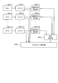
- FIG. 1 is an example of a schematic configuration diagram of a defect inspection device 100 according to the present embodiment.
- the defect inspection device 100 according to the present embodiment targets a sample 1 having a flat surface on which no pattern is formed on the surface, and inspects defects such as foreign matter and dents on the surface of the sample 1.
- the defect inspection device 100 includes an illumination unit 101, a light collection detection unit 102-1 to 102-3, a sensor unit 103-1 to 103-3, a sensor shift means 104-1 to 104-2, a stage 105, and a sensor unit 103-. 4 is provided.
- the defect inspection device 100 further includes a condenser lens 91, an imaging lens 92, a two-dimensional sensor 93, a signal processing unit 5200, a control unit 53, a display unit 54, and an input unit 55.
- the control unit 53 controls the defect inspection device 100 in an integrated manner together with a display unit 54 for displaying information and an input unit 55 for inputting data, instructions, and the like.
- the sensor units 103-1 to 103-3 photoelectrically convert the optical image collected by the condensing detection units 102-1 to 102-3 and output it as an electric signal.
- the stage 105 places the wafer, which is the sample 1, on the stage 105.
- the condensing detection units 102-1 to 102-3 control the polarization state of the incident light by condensing the reflected light of the illumination spot irradiated to the sample 1 by the illumination unit 101, and the sensor units 103-1 to 103.
- An optical image is formed on the array-shaped light receiving part of -3.
- the sensor unit 103-4 photoelectrically converts the optical image collected by the focusing detection unit 102-3 and outputs it as an electric signal.
- the two-dimensional sensor 93 photoelectrically converts the optical image formed by the condenser lens 91 and the imaging lens 92 and outputs it as an electric signal.
- the illumination unit 101 appropriately includes a laser light source 2, an attenuator 3, an emission light adjustment unit 4, a beam expander 5, a polarization control unit 6, and a condensing optical unit 7.
- the light collection detection unit 102-3 is also used as a light collection means for illuminating light when light is incident from the normal direction of the sample 1.
- Each sensor unit 103-1 to 103-3 is a line sensor, and a CMOS (Complementary Metal-Oxide-Semiconductor) sensor or a CCD (Charge Coupled Device) sensor is used.
- CMOS Complementary Metal-Oxide-Semiconductor
- CCD Charge Coupled Device
- Each of the sensor units 103-1 to 103-3 includes an array-shaped light receiving unit and an antireflection film at a position conjugate with the illumination spot irradiated on the surface of the sample 1.
- the sensor shift means 104-1 physically shifts the sensor unit 103-1 to suppress the shift of the optical image due to this height fluctuation.
- the sensor shift means 104-2 has a similar function. For example, an ultrasonic linear actuator may be applied to the sensor shift means 104-1 and 104-2.
- the signal processing unit 5200 includes a lighting spot position analysis unit 520, a memory unit 521, a signal integration unit 522, and a defect detection unit 523.
- the sensor units 103-1 to 103-3 photoelectrically convert the optical image, perform predetermined sampling, and output digital data by analog-digital conversion.
- the illumination spot position analysis unit 520 analyzes the position of the illumination spot from the digital data and stores it in the memory unit 521 as scattered light data.
- the signal integration unit 522 Based on this scattered light data, performs an integration calculation between data in which the positions of the illumination spots 20 are different in the same sensor unit 103, and further performs an integration calculation between different sensor units 103.
- the defect detection unit 523 extracts the high-frequency / high-luminance unit in the data after performing the integrated calculation as a defect.
- the laser beam emitted from the laser light source 2 is adjusted to a desired beam intensity by the attenuator 3, and is adjusted to a desired beam position and beam traveling direction by the emitted light adjusting unit 4. Further, the laser beam is adjusted to a desired beam diameter by the beam expander 5, adjusted to a desired polarization state by the polarization control unit 6, and is illuminated in the inspection target region of the sample 1 which is a wafer.
- the angle of incidence of the illumination light on the surface of the sample 1 (the inclination angle of the surface of the sample 1 with respect to the normal direction) is determined by the positions and angles of the reflection mirrors 80 and 82 arranged in the optical path of the illumination unit 101.
- the incident angle of the optical axis 120 of the illumination light is set to an angle suitable for detecting minute defects.
- the adjustment mechanism unit 81 adjusts the angle of the reflection mirror 80.
- the incident angle of the illumination light on the surface of the sample 1 is preferably 75 degrees or more and less than 90 degrees (elevation angle 15 degrees). It is better to set it below and above 0 degrees).
- the incident angle of the illumination light on the surface of the sample 1 is preferably 60 degrees or more and 75 degrees or less (elevation angle 15 degrees or more and 30 degrees or less). It is good to set.
- the polarization of the illumination is changed to P-polarized light by the polarization control in the polarization control unit 6 of the illumination unit 101, so that the scattered light from the defect on the surface of the sample 1 is compared with other polarized light. Will increase.
- the polarization of the illumination is set to S-polarized light, so that the minute irregularities on the surface of the sample 1 can be compared with other polarized light. Scattered light is reduced.
- the polarized light of the illumination can be set to 45 degree polarized light, which is between P and S, or circularly polarized light.
- the reflection mirror 82 can be moved in and out of the optical path by moving it up and down in the Z-axis direction using a drive mechanism (not shown).
- a drive mechanism not shown.
- the illumination light emitted from the polarization control unit 6 is transmitted from the direction perpendicular to the sample 1 via the reflection mirror 83, the polarization beam splitter 84, the polarization control unit 85, and the focusing detection unit 102-3. Be incidented.
- the light collection detection unit 102-3 includes a reflection mirror 102-33 in its pupil portion.
- the polarization control unit 85 includes a 1/4 wave plate 851 and a 1/2 wavelength plate 852, and can be controlled to any polarization. Under the condition that the reflection mirror 82 is removed from the optical path and the illumination is vertically incident, the polarization control unit 85 sets the illumination light to be incident on the condensing detection unit 102-3 with circularly polarized light.
- the light reflected on the surface of sample 1 is optical path branched by the reflection mirror 102-33.
- the reflected light from the sample 1 reflected on the side of the polarization control unit 85 by the reflection mirror 102-33 is converted into linearly polarized light by the 1/4 wave plate 851 of the polarization control unit 85.
- the light is guided to the imaging lens 102-34 by the polarizing beam splitter 84 and detected by the sensor unit 103-4.
- FIG. 2A and 2B show the detailed configuration of the light collection detection unit 102-3.
- FIG. 2B is an arrow view of a cross section taken along the line AA in FIG. 2A.
- An objective lens 102-31, a reflection mirror 102-33, and an imaging lens 102-32 are arranged on the optical axis of the condensing detection unit 102-3, and an optical image is formed on the sensor unit 103-3. It is configured to do.
- the upward arrow in FIG. 2A is the Z axis, and the horizontal arrow is the direction S2 indicating the scanning direction.
- the illumination spot 20 is illumination light applied to the surface of the sample 1 and has a linear intensity distribution.
- the reflection mirrors 102-33 have a shape that is long in the minor axis direction and short in the major axis direction of the illumination spot 20.
- the reflected light incident on the reflection mirrors 102-33 from the sample 1 is guided to the polarization control unit 85.
- the reflected light that has passed around the reflection mirror 102-33 is incident on the imaging lens 102-32.
- the amount of light detected by the sensor unit 103-4 is very weak under the condition of oblique illumination in which the reflection mirror 82 is inserted into the optical path. Therefore, in the present embodiment, the two-dimensional sensor 93 is used instead of the sensor unit 103-4. That is, in the present embodiment, the reflected light directly reflected on the surface of the sample 1 is incident on the condenser lens 91 and the imaging lens 92 to form an image on the two-dimensional sensor 93.
- the defect inspection device 100 monitors the illumination spot 20 using the light detected by the sensor unit 103-4 or the two-dimensional sensor 93.
- the laser light source 2 emits a laser beam having a wavelength that is difficult to penetrate inside the sample 1 in order to detect minute defects near the surface of the sample 1. That is, the laser light source 2 emits a short wavelength (wavelength 355 nm or less) ultraviolet or vacuum ultraviolet laser beam at a high output of 2 W or more. In this embodiment, a laser beam having a wavelength of 266 nm is applied. Not limited to this, any wavelength included in near-ultraviolet rays having a wavelength of 200 to 380 nm or vacuum ultraviolet rays having a wavelength of 10 to 200 nm may be used.
- the emission beam diameter of the illumination unit 101 is about 1 mm.
- a wavelength that oscillates a visible or infrared laser beam is used as a wavelength that easily penetrates into the inside of the sample 1.
- FIG. 3 is a diagram showing the configuration of the attenuator 3.
- the attenuator 3 appropriately includes a first polarizing plate 31, a 1/2 wave plate 32 that can rotate around the optical axis of the illumination light, and a second polarizing plate 33.
- the light incident on the attenuator 3 is converted into linearly polarized light by the first polarizing plate 31, and the polarization direction is rotated in an arbitrary direction according to the slow axis azimuth angle of the 1/2 wave plate 32. It passes through the polarizing plate 33.
- the attenuator 3 uses a pre-calibrated relationship between the input signal and the dimming rate.
- an ND (Neutral Density) filter having a gradation density distribution can be used, or ND filters having a plurality of different densities can be switched and used.
- the emitted light adjusting unit 4 includes a plurality of reflecting mirrors 41 and 42.
- a plurality of reflecting mirrors 41 and 42 Here, an embodiment in the case of being composed of two reflection mirrors 41 and 42 will be described, but the present invention is not limited to this, and three or more reflection mirrors may be appropriately used.
- a three-dimensional Cartesian coordinate system (XYZ coordinates) is tentatively defined, and it is assumed that the incident light on the reflection mirror 41 is traveling in the + X direction.
- the reflection mirror 41 is installed so as to deflect the incident light in the + Y direction. That is, the incident light is incident and reflected in the XY plane in the reflection mirror 41.
- the reflection mirror 42 is installed so as to deflect the light reflected by the reflection mirror 41 in the + Z direction. That is, the incident light is incident and reflected in the YZ plane by the reflection mirror 42.
- Each of the reflection mirrors 41 and 42 is translated and the tilt angle is adjusted by using a mechanism (not shown). As a result, the position and the traveling direction (angle) of the light emitted from the emitted light adjusting unit 4 are adjusted.
- the incident / reflective surface (XY plane) of the reflective mirror 41 and the incident / reflective surface (YZ plane) of the reflective mirror 42 are arranged so as to be orthogonal to each other.
- the position and angle adjustment of the light emitted from the emitted light adjusting unit 4 (progressing in the + Z direction) in the XZ plane and the position and angle adjustment in the YZ plane can be performed independently.
- the beam expander 5 has lens groups 51 and 52 and has a function of expanding the diameter of the incident parallel luminous flux.
- the beam expander 5 is a Galileo type in which the lens group 51 is a concave lens and the lens group 52 is a convex lens.
- the beam expander 5 is installed on a translational stage having two or more axes (not shown), and its position can be adjusted so that the center coincides with a predetermined beam position. Further, a tilt angle adjusting function for the entire beam expander 5 is provided so that the optical axis of the beam expander 5 and a predetermined beam optical axis coincide with each other.
- the spacing between the lens groups 51 and 52 By adjusting the spacing between the lens groups 51 and 52, it is possible to control the magnification of the luminous flux diameter (zoom mechanism).
- the diameter of the luminous flux is expanded and collimated (quasi-parallel light flux) is performed at the same time by adjusting the spacing between the lens groups 51 and 52.
- the collimating of the luminous flux may be performed by installing a collimating lens upstream of the beam expander 5 independently of the beam expander 5.
- the magnification of the beam diameter by the beam expander 5 is about 5 to 10 times, and the beam having a beam diameter of 1 mm emitted from the light source is expanded to about 5 mm to 10 mm.
- the polarization control unit 6 includes a 1/2 wavelength plate 61 and a 1/4 wavelength plate 62, and controls the polarization state of the illumination light to an arbitrary polarization state.
- FIGS. 4 and 5 show a schematic diagram of the positional relationship between the optical axis 120 of the illumination light guided from the illumination unit 101 to the surface of the sample 1 and the illumination intensity distribution shape.
- the configuration of the illumination unit 101 in FIGS. 4 and 5 shows a part of the configuration of the illumination unit 101 described in FIG. 1, and the emission light adjustment unit 4 and the reflection mirror 82 described in FIG. 1
- the adjustment mechanism portion 81 and the like are omitted.
- FIG. 4 shows a schematic view of a cross section of an incident surface of oblique incident illumination.
- the incident surface is a surface including the optical axis 120 of the illumination light and the normal of the surface of the sample 1.
- the oblique incidence illumination is inclined with respect to the surface of the sample 1 in the incident surface.
- the illumination unit 101 creates a uniform illumination intensity distribution in the incident surface.
- the illumination intensity has a Gaussian intensity distribution in the linearly illuminated region on the surface of the sample 1, and the beam width is defined by 13.5% of the peak.
- the length of L1 is about 25 ⁇ m to 4 mm.
- FIG. 5 shows a schematic cross section including the normal of the surface of the sample 1 and perpendicular to the incident surface of the oblique incident illumination.
- the illumination intensity distribution on the surface of the sample 1 is such that the peripheral intensity is weak with respect to the center of the optical axis 120 on the surface of the sample 1, as shown in the illumination intensity distribution 1202 on the right side of FIG. It forms an intensity distribution. More specifically, it is similar to the Gaussian distribution that reflects the intensity distribution of the light incident on the condensing optical unit 7, or the first-class first-order Bessel function or sinc function that reflects the opening shape of the condensing optical unit 7.
- the intensity distribution is as follows.
- the length L2 of the illumination intensity distribution in the plane is shorter than the length of the portion where the illumination intensity is uniform in the incident surface in order to reduce the haze generated from the surface of the sample 1, and is about 1.0 ⁇ m to 20 ⁇ m. Is.
- the length L2 of the illumination intensity distribution refers to the length of the region having an illumination intensity of 13.5% or more of the maximum illumination intensity.
- the stage 105 includes a translation stage, a rotation stage, and a Z stage (none of which is shown) for adjusting the height of the sample surface.
- the illumination spot 20 has a long illumination intensity distribution in one direction as described above, and this is the direction S2 (the direction of L1 in FIG. 4).
- the direction S1 (the direction of L2 in FIG. 5) is orthogonal to the direction S2.
- the illumination spot 20 is operated in the direction S1 of the circumference of a circle about the rotation axis of the rotation stage by the rotational movement of the rotation stage constituting the stage 105. Further, the illumination spot 20 is scanned in the direction S2 of the translation stage by the translation motion of the translation stage.
- the illumination spot is scanned for a distance equal to or less than the longitudinal length of the illumination spot 20 in the scanning direction S2 during one rotation of the sample 1.
- 20 draws a spiral locus T1 on the sample 1, and the entire surface of the sample 1 is scanned.
- FIG. 8 shows a scan of the illumination spot 20 in a configuration with a two-axis translational stage instead of a rotating stage.
- the illumination spot 20 scans the sample surface in the direction S1 in a strip shape with the length of the illumination spot 20 at a constant speed.
- the translational stage is moved in the direction S2 by the scanning width to move the field of view, and scanning is repeated at a constant speed in the direction opposite to the direction S1 to draw a locus T2, and the sample 1 is drawn. The entire surface of is scanned.
- FIG. 9A and 9B show a block diagram of the condensing detection unit 102 that detects the optical image 22 of the illumination spot 20 from the side and the top of the light receiving unit of the sensor unit 103. This corresponds to the light collection detection units 102-1 to 102-2.
- FIG. 9A is a view seen from the arrangement direction of the light receiving units of the sensor units 103-1 and 103-2 and the + Y direction of FIG.
- FIG. 9B is a view seen from the direction orthogonal to the arrangement of the light receiving units 1031 of the sensor units 103-1 and 103-2 and the ⁇ Z direction of FIG.
- the condenser lens 1021 is a telecentric optical system so that the magnification does not change even when the working distance changes.
- the condensing detection unit 102 has a condensing lens 1021, a 1/2 wave plate 1022, a polarizing beam splitter 1023, a 1/2 wave plate 1024, a cylindrical lens 1025, 1026, and an imaging lens 1027 in the direction of the optical axis 121. Be prepared.
- the focusing detection unit 102 includes a beam diffuser 1028 in the direction of the light separated by the polarization beam splitter 1023.
- the condensing detection unit 102 condenses light with a condensing lens 1021 and controls the polarization direction with the 1/2 wavelength plate 1022.
- the 1/2 wavelength plate 1022 can be rotated by a drive unit (not shown).
- the polarization beam splitter 1023 branches the optical path by polarization.
- the combination of the 1/2 wave plate 1022 and the polarizing beam splitter 1023 makes it easy to separate the optical signal indicating the defect of the sample and the optical signal indicating the defect detection of the sample (for example, the roughness scattered light from the sample surface). ing. That is, the condensing detection unit 102 condenses the reflected light of the illumination spot from the surface of the sample 1 and controls the polarization state of the incident light to form an optical image.
- the optical axis 121 is inclined with respect to the normal direction of the light receiving unit 1031. Therefore, in this method, the light absorption rate of the light receiving unit 1031 changes depending on the polarization, unlike the normal case where the light is irradiated from the normal direction of the light receiving unit.
- the 1/2 wave plate 1024 controls the polarization direction so that the light absorption rate of the light receiving unit 1031 becomes high.
- the paired cylindrical lenses 1025 and 1026 constitute a cylindrical beam expander, and the spread of the optical image 22 formed by the illumination spot 20 in the lateral direction ⁇ is made smaller than the spread of the optical image 22 in the longitudinal direction. ing.
- the imaging lens 1027 forms an optical image 22 of the illumination spot 20 on the light receiving unit 1031 of the sensor unit 103.
- the beam diffuser 1028 prevents unwanted light from becoming stray light.
- the linear illumination spot 20 irradiated on the surface of the sample 1 is arranged parallel to the longitudinal direction of the optical image 22 in which the light collecting detection unit 102 forms an image on the light receiving unit 1031. NS.
- the sensor unit 103 takes an image of the optical image 22 and outputs it as an electric signal.
- the sensor unit 103 includes an array-shaped light receiving unit and an antireflection film at a position conjugate with the illumination spot irradiated on the surface of the sample 1.
- the light receiving surface of the sensor unit 103 is not conjugate with the sample surface in the lateral direction ⁇ .
- the lateral direction ⁇ is also the lateral direction of the illumination spot 20
- the image height of the optical image 22 is low, and almost no defocus occurs. Therefore, by increasing the image magnification of the optical image 22 in the lateral direction ⁇ , it is possible to reduce the variation in the angle of incidence on the light receiving unit 1031.
- optical axis 121 for detecting the light of the condensing detection unit 102 is deviated by an angle ⁇ with respect to the normal direction of the sample 1 and an angle ⁇ with respect to the longitudinal direction of the illumination spot 20, this is assumed in the three-dimensional space.
- the optical axis 121 is represented by the vector v0 of the following equation (1).
- the defect inspection device 100 detects a section of 2 L in the longitudinal direction of the illumination spot 20 by the sensor unit 103.
- the working distance changes as ⁇ Z represented by the following equation (3).
- the imaging magnification M is determined by the condenser lens 1021 and the imaging lens 1027.
- the position of the image formed here is expressed by the following equation (4).
- the line sensor is arranged so as to be orthogonal to the optical axis which is the center of the light flux emitted by the imaging lens.
- the pixel alignment vector v1 of the optical axis 121 and the light receiving surface incident on the sensor unit 103 is in the longitudinal direction of the illumination spot 20 and in the plane stretched by the vector v0, and satisfies the following equation (5).
- the imaging magnification M increases, the inner product of the vector v0 and the vector v1 increases. That is, the angle ⁇ formed by the vector v0 and the vector v1 becomes smaller, and the imaging performance deteriorates.
- the angle ⁇ can be obtained from the inverse cosine function of Eq. (5). For example, when the angle ⁇ is 60 °, if the imaging magnification M is 2, the incident angle becomes 0 °, and even if the incident numerical aperture is 0, imaging cannot be performed. In order to prevent this, the imaging magnification M is set to 2 times or less.
- the angle formed by the optical axis 121 and the vector v1 incident on the sensor unit 103 from the imaging lens 1027 can be maximized.
- the numerical aperture of the incident light beam of the condenser lens 1021 is N
- the spread of the light beam emitted to the sensor unit 103 is the reciprocal of the imaging magnification M.
- the imaging magnification M is set to 1x or more. As a result, the angle ⁇ becomes smaller with respect to the angle ⁇ , and typically becomes smaller by 5 degrees or more by giving a magnification of about 1.2 times.
- the imaging magnification M is 2 times or less is imaging magnification M X of arrangement direction of the array of the light receiving portion of the sensor unit 103.
- the image magnification M Y this respect is short direction gamma, the incidence angle variation of incident light on the light receiving portion 1031 of the sensor portion 103 is reduced. Therefore, by improving the light absorption rate of the light receiving unit 1031, it is possible to improve the sensitivity of the sensor unit 103. Therefore, it is desirable to increase the imaging magnification M Y than the imaging magnification M X.
- the normal direction n of the sample 1 is typically not orthogonal to the longitudinal direction ⁇ of the light receiving portion 1031 and the lateral direction ⁇ in FIG. 9A when the light receiving portion 1031 of the sensor unit 103 is viewed from the side.
- FIG. 9C shows a schematic diagram of the three-dimensional detection of the sample 1.
- the optical axis 121 of the condensing detection unit 102 is inclined by an angle ⁇ with respect to the normal direction n of the sample 1.
- the projection of the optical axis 121 onto the sample surface is inclined by an angle ⁇ with respect to the longitudinal direction S2 of the illumination spot 20.
- FIG. 9D illustrates the fluctuation direction of the optical image 22 in the light receiving unit 1031 of the sensor unit 103 at this time.
- the optical image 22 shifts in the direction U1.
- the optical image 22 shifts in the direction U2.
- the optical image 22 shifts in the direction m.
- the sample 1 shown in FIG. 9C has no height fluctuation in the normal direction n.
- the optical image 22 shifts in the direction m. That is, due to the fluctuation of the height of the sample 1, the position of the optical image 22 shifts in the longitudinal direction ⁇ of FIG. 9A in proportion to cos (a) and in the lateral direction ⁇ in proportion to sin (a). do.
- the optical image 22 shifts in the lateral direction ⁇ , it deviates from the light receiving unit 1031 of the sensor unit 103, so that the amount of light decreases.
- the optical image 22 shifts in the longitudinal direction ⁇ , the imaging position in the longitudinal direction of the sample 1 changes.
- the light receiving unit 1031 of the sensor unit 103 is a two-dimensional sensor in which predetermined image pickup elements are arranged in both the longitudinal direction ⁇ and the lateral direction ⁇ .
- the control unit 53 measures the deviation of the optical image 22 in the lateral direction ⁇ by the light receiving unit 1031 which is a two-dimensional sensor, and measures the fluctuation of the height of the sample 1.
- control unit 53 physically shifts the sensor unit 103 by the sensor shift means 104-V and 104-H based on the fluctuation of the height of the sample 1, and suppresses the shift of the optical image 22 due to the height fluctuation. do.
- the sensor shift means 104-V and 104-H an ultrasonic linear actuator may be applied.
- FIG. 9C is a block diagram of a condensing detection unit 102 that detects an image of the illumination spot from a direction orthogonal to the longitudinal direction of the illumination spot 20 as viewed from the light receiving unit and the direction of the sensor unit 103.
- FIG. 9C corresponds to the light collection detection unit 102-3.
- the sensor unit 103 is arranged so that the center of the light flux incident from the imaging lens 1027 is orthogonal to the arrangement direction of the pixels of the sensor unit 103.
- FIG. 10 shows a cross-sectional configuration diagram of the image pickup sensor 1036 constituting the sensor unit 103.
- the image sensor 1036 is configured by laminating an antireflection film 1033, a light receiving portion 1031, and a wiring portion 1032 in order from the surface.
- the incident lights 122A to 122C are lights incident on the image pickup sensor 1036.
- the incident light 122A is the light on the optical axis 121 shown in FIGS. 9A and 9B.
- the incident lights 122B and 122C are lights incident from an angle different from that of the optical axis 121.
- the antireflection film 1033 is a film for preventing surface reflection of each incident light 122A to 122C.
- the light receiving unit 1031 has an array shape, and performs photoelectric conversion for each divided region, that is, for each pixel.
- the wiring unit 1032 independently takes out the electricity output by the light receiving unit 1031 to the outside.
- the sensor having the structure in which the light receiving unit 1031 is on the light incident side of the wiring unit 1032 is known as a back side illumination sensor.
- the incident light is incident at a predetermined angle from the normal direction of the light receiving portion. Therefore, in a CMOS image sensor known as FSI (Front side Illumination), which has a structure in which the wiring portion is on the incident side of light, the wiring portion absorbs the light, and sufficient light cannot be incident on the light receiving portion.
- FSI Front side Illumination
- the antireflection film 1033 cannot obtain good sensitivity to these incident lights 122A to 122C unless it has a high absorption rate.
- the antireflection film of an image sensor is formed assuming that the incident angle of light is near 0 degrees. This will be described with reference to FIG.
- Curve 10331 shows the characteristics of the absorption rate of S-polarized light.
- Curve 10332 shows the characteristics of the absorption rate of P-polarized light.
- Figure 12A is a graph showing characteristics of the anti-reflection film 1033 formed of a single layer of HfO 2 25 nm.
- the horizontal axis of the graph shows the angle of incidence, and the vertical axis of the graph shows the absorption rate.
- Curve 10333 is a characteristic of the absorption rate of S-polarized light.
- Curve 10334 is a characteristic of the absorption rate of P-polarized light. The absorption rate of P-polarized light decreases as the incident angle increases, but the absorption rate decreases to 0.5 when the incident angle is around 60 degrees.
- the incident angle of S-polarized light has increased to about 70 degrees, and the absorption rate is 70% or more in the region where the incident angle is 0 to 80 degrees.
- the sensor units 103-1 and 103-2 need to be tilted by a predetermined angle in order to realize image detection without defocus regardless of the change in the working distance in the field of view. That is, it is desirable that the normal of the light receiving surface of the sensor unit 103-1 is inclined by, for example, 10 to 80 degrees from the optical axis 121-1 of the condensing detection unit 102-1.
- the rotation angle of the 1/2 wavelength plate 1024 of FIG. 9A so that S-polarized light is incident on the sensor unit 103. Further, by increasing the magnification of the expander formed by the paired cylindrical lenses 1025 and 1026 of FIG. 9B, it is possible to realize a substantially linear polarization incident.
- HfO 2 is used as the antireflection film 1033, but Si 3 N 4 is a substance having a similar refractive index with respect to incident light having a wavelength of 266 nm.
- the refractive index of HfO 2 with respect to the incident light having a wavelength of 266 nm is (2.1,0).
- the refractive index of Si 3 N 4 with respect to the incident light having a wavelength of 266 nm is (2.21, 0.0013).
- Si 3 N 4 Since the extinction coefficient of Si, which is the light receiving surface, is large, the antireflection film 1033 can easily obtain good absorptivity characteristics when the refractive index is large.
- Si 3 N 4 has a higher refractive index than HfO 2, but has a problem that the extinction coefficient is not zero.
- the absorption rate characteristics of Si 3 N 4 are almost the same as those of HfO 2.
- the antireflection film 1033 has a thickness of 22 nm to 29 nm for both Si 3 N 4 and HfO 2.
- the absorption characteristics of HfO 2 having film thicknesses of 21 nm and 30 nm on the silicon surface are shown.
- Figure 12B is a graph showing characteristics of the anti-reflection film 1033 formed of a single layer of HfO 2 21 nm.
- the horizontal axis of the graph shows the angle of incidence, and the vertical axis of the graph shows the absorption rate.
- Curve 10339 is an absorptivity characteristic of S-polarized light incident.
- Curve 10330 is an absorptivity characteristic of P-polarized light incident. At a film thickness of 21 nm, the curves 10339 and 10330 are flat from an incident angle of about 0 to 45 degrees, but the absorption rate decreases at an incident angle of more than that.
- Figure 12C is a graph showing characteristics of the anti-reflection film 1033 formed of a single layer of HfO 2 30 nm.
- the horizontal axis of the graph shows the angle of incidence, and the vertical axis of the graph shows the absorption rate.
- Curve 10339a is an absorption rate characteristic of S-polarized light incident.
- Curve 10330a is an absorptivity characteristic of P-polarized light incident.
- the absorption rate of P-polarized light incident increases when the incident angle is around 75 degrees, but P-polarized light increases in the region where the incident angle is 45 degrees or less. The absorption rate of incident decreases.
- the characteristics with respect to the incident light of 266 nm are shown, but the wavelength of the incident light may have a predetermined deviation, for example, 240 nm to 293 nm.
- HfO 2 has a large refractive index but a relatively small extinction coefficient up to a wavelength near 190 nm. Therefore, the antireflection film 1033 using HfO 2 can realize good sensor sensitivity in the wavelength region of 190 to 266 nm.
- Figure 12D is a graph showing the characteristics of the SiN 36.8nm, SiO 2 90nm of antireflection film 1033 which is formed of two layers.
- the horizontal axis of the graph shows the angle of incidence, and the vertical axis of the graph shows the absorption rate.
- Curve 10335 shows the absorption rate characteristic of S-polarized light.
- Curve 10336 shows the absorption rate characteristic of P-polarized light.
- the normal of the light receiving surface of the sensor unit 103-1 is inclined by, for example, 45 to 55 degrees from the optical axis 121-1 of the condensing detection unit 102-1.
- the region where the absorption rate is good is a section where the incident angle is 45 to 55 degrees and the width is about 10 degrees, and when the numerical aperture of the condenser lens 1021 is large, it is said that the characteristics are good. I can't say.
- FIG. 12E SiN 36.8nm, SiO 2 46nm, SiN 33.5 nm, is a graph showing characteristics of the anti-reflection film 1033 formed by SiO 2 94 nm.
- the horizontal axis of the graph shows the angle of incidence, and the vertical axis of the graph shows the absorption rate.
- the absorption rate characteristic of S-polarized light shown by the curve 10337 is very good at an incident angle of 50 degrees, but the incident angle range in which the absorption rate is good is narrower than that of the two-layer state shown in FIG.
- the absorption rate of P-polarized light indicated by 10338 is inferior to that of S-polarized light at its peak position.
- it is desirable that the normal of the light receiving surface of the sensor unit 103-1 is inclined by, for example, 45 to 55 degrees from the optical axis 121-1 of the condensing detection unit 102-1.
- Both the characteristics of the antireflection film 1033 shown in FIGS. 12D and 12E are such that the SiN film on the incident side of light is about 37 nm, which is thicker than the film thickness of the 27 nm SiN film shown in FIG. As a result, in the present embodiment, the reflection of the SiN film on the large incident film and the reflection from the light receiving portion formed of Si are interfered with each other to suppress the reflection and improve the absorption rate.
- the antireflection film 1033 Is preferably formed in one layer.
- the peak characteristics of the two-layer curve 10335 and the peak characteristics of the four-layer curves 10336 and 10337 are better than the characteristics of the curve 10333. In order to take advantage of this good absorption rate characteristic, it is preferable to collimate the light incident on the sensor unit 103.
- FIG. 13 is a diagram showing an image pickup sensor 1036a that collimates incident light.
- the image sensor 1036a is configured by laminating a cylindrical lens array 1035, an antireflection film 1033, a light receiving portion 1031, and a wiring portion 1032 in order from the surface.
- the antireflection film 1033, the light receiving unit 1031, and the wiring unit 1032 are the same as the image sensor 1036 shown in FIG.
- the cylindrical lens array 1035 is an array of cylindrical lenses made of synthetic quartz.
- the lens pitch of the cylindrical lens array 1035 is formed to be equal to the pitch of the light receiving unit 1031.
- the cylindrical lens array 1035 is arranged so that the light flux emitted from the imaging lens 1027 (FIGS. 9A to 9C) is imaged in the cylindrical lens array 1035 and the light emitted from the cylindrical lens array 1035 is collimated. There is. The pitch of the cylindrical lens array 1035 and the light receiving unit 1031 is shifted so that the light collimated by each cylindrical lens is incident on each pixel of the light receiving unit 1031.
- the antireflection film 1033 can be composed of two layers or four layers.
- the image sensor 1036-1 is included in the sensor unit 103-1.
- the image pickup sensor 1036-2 is included in the sensor unit 103-2.
- the image sensor 1036-3 is included in the sensor unit 103-3.
- the illumination spot 20 of the sample 1 is illuminated by irradiation with a laser beam. Defects 15 are formed on the surface of sample 1.
- the optical image 22-1 of the illumination spot 20 and the optical image 151-1 of the defect 15 are imaged on the surface of the image sensor 1036-1.
- An optical image 22-2 of the illumination spot 20 and an optical image 151-2 of the defect 15 are formed on the surface of the image sensor 1036-2.
- An optical image 22-3 of the illumination spot 20 and an optical image 151-3 of the defect 15 are formed on the surface of the image sensor 1036-3.
- the illumination spot 21 is a region in which the surface of the sample 11 is illuminated with a predetermined illumination intensity by irradiation with a laser beam, and the position of the illumination spot 21 is displaced as the sample 1 is displaced by ⁇ Z.
- the defect 16 is a defect 15 of the sample 1 displaced by ⁇ Z.
- an optical image 23-1 of the illumination spot 21 and an optical image 161-1 of the defect 16 are formed on the surface of the image sensor 1036-1.
- An optical image 23-2 of the illumination spot 21 and an optical image 161-2 of the defect 16 are formed on the surface of the image sensor 1036-2.
- An optical image 23-3 of the illumination spot 21 and an optical image 161-3 of the defect 16 are formed on the surface of the image sensor 1036-3.
- the optical axis 121-1 of the condensing detection unit 102-1 and the optical axis 122-2 of the condensing detection unit 102-2 are line-symmetric with respect to the normal of the sample 1. Further, the optical axis 122-3 of the condensing detection unit 102-3 coincides with the normal direction of the surface of the sample 1.
- the illumination spot 20 shifts to the position of the illumination spot 21 due to the displacement of the sample 1 by ⁇ Z.
- the amount of deviation ⁇ spot of the position of the optical image 23 of the illumination spot 21 with respect to the optical image 22 of the illumination spot 20 is expressed by the following equation (6).
- ⁇ is the deviation of the illumination spot 21.
- the elevation angle of the light collection detection unit 102-2 is ⁇ 2
- the amount of deviation ⁇ S2_2 is expressed by the following equation (7).
- the amount of deviation ⁇ S2_1 between the optical image 161-1 of the defect 16 formed on the image sensor 1036-1 and the optical image 151-1 of the defect 15 is opposite to that of ⁇ S2_2.
- the amount of deviation ⁇ spot2 of the optical image 23-2 of the illumination spot 21 in the image sensor 1036-2 from the optical image 22-2 of the illumination spot 20 is represented by the following equation (8).
- the amount of deviation ⁇ spot1 from the optical image 22-1 of the illumination spot 20 of the optical image 23-1 of the illumination spot 21 in the image sensor 1036-1 is represented by the following equation (9).
- ⁇ spot1 and ⁇ spot2 calculates the center of gravity of the haze amount of the image sensor 1036-1, and imaging sensors 1036-2, seeking 2 ⁇ Z / tan ⁇ 2, by obtaining the ⁇ S2_2 the equation (7), defects in the sensor plane 15 The amount of deviation of the optical image can be obtained.
- the positional deviation of the illumination spot 21 with respect to the direction S1 cannot be measured. Therefore, the positional deviation of the illumination spot 21 with respect to the direction S1 may be measured by the two-dimensional sensor 93 or the sensor unit 103-4.
- FIG. 15 shows a block diagram of data processing processed by the signal processing unit 5200 and its operation.
- the sensors 103-A to 103-N each transfer data for m pixels to the signal processing unit 5200.
- the illumination spot position analysis unit 520 calculates the deviation amount ⁇ Z by the equation (10), and then applies a bandpass filter in the time direction, that is, the direction S1 to extract a defect signal.
- the illumination spot position analysis unit 520 stores the extracted data in the memory unit 521.
- Blocks 521A to 521N correspond to sensors 103-A to 103-N, respectively.
- the blocks 521Aa to 521Am show the data of the spiral scan from a to m circumference of the sensor 103-A.
- Blocks 521Na to 521Nm show the data of the spiral scan from a to m circumference of the sensor 103-N.
- the signal integration unit 522 includes the sensor-to-sensor integration units 5220-1 to 5220-n.
- the inter-sensor integration units 5220-1 to 5220-n synthesize a linear sum signal obtained by multiplying each signal of the sensors A to N stored in the memory unit 521 by a predetermined gain.
- the detected defect causes a positional deviation in the direction S2 different in each sensor unit 103 due to the height fluctuation of the sample surface. Therefore, in the present embodiment, in consideration of this positional deviation, the data is read from the memory so as to synthesize the data indicating the same position on the sample surface.
- scan data 5220a-1 ⁇ 5220m-1 of a ⁇ m circumference is obtained by combining with a predetermined gain set G 1.
- the scan data 5220an to 5220mn in the a to m circumference are synthesized using a predetermined gain set G n.
- the light amount calculation units 5221-1 to 5221-n synthesize the scanning data from a to m circumferences obtained by scanning the same location multiple times, and calculate the light amount of the defect candidate.
- the sensor unit 103-4 or the two-dimensional sensor 93 measures and corrects the amount of deviation in the direction S1, and corrects the data obtained by different scanning.
- the defect detection unit 523 determines that the defect is a defect when any of the light amounts of the defect candidates calculated by the light amount calculation units 5221-1 to 5221-n exceeds the threshold value set for each gain set. Information on the amount of defective light and the position where the defect is detected is output to the control unit 53 shown in 1.
- the control unit 53 causes a display unit 54 or the like to display information on the amount of defective light and the position where the defect is detected.
- the width of the illumination spot 20 may be narrowed. However, if the width of the illumination spot 20 is narrowed, the power density of the light applied to the sample 1 increases, and the sample 1 is damaged. Therefore, in the fifth embodiment, the sensitivity is improved by using a sensor that performs integral exposure in the width direction of the optical image 22. In the fifth embodiment, light passing through both optical paths branched by the polarizing beam splitter 1023 is detected and added.
- FIG. 16A is a diagram corresponding to the arrangement direction of the light receiving units 1031 of the sensor unit 103 of FIG. 1 and the view from the + Y direction of FIG.
- FIG. 16B is a diagram corresponding to the arrangement of the light receiving units 1031 of the sensor unit 103 of FIG. 1 in the orthogonal direction and the view from the ⁇ Z direction of FIG.
- the condensing detection unit 102 condenses the reflected light of the illumination spot from the surface of the sample 1 and controls the polarization state of the incident light to form an optical image.
- the condensing detection unit 102 includes a condensing lens 1021, a 1/2 wave plate 1022, a polarizing beam splitter 1023, a 1/2 wave plate 1024, a cylindrical lens 1025, 1020, 1026, and an imaging lens in the direction of the optical axis 121. It is equipped with 1027.
- the focusing detection unit 102 further includes a 1/2 wavelength plate 1024b, cylindrical lenses 1025b, 1020b, 1026b, and an imaging lens 1027b in the direction of the light separated by the polarizing beam splitter 1023.
- the difference between the light collection detection unit 102 shown in FIG. 9A and FIG. 9B will be described.
- the condensing detection unit 102 condenses light with a condensing lens 1021 and controls the polarization direction with the 1/2 wavelength plate 1022.
- the 1/2 wavelength plate 1022 can be rotated by a drive unit (not shown).
- the polarization beam splitter 1023 branches the optical path by polarization.
- a 1/2 wave plate 1024, a cylindrical lens 1025, 1020, 1026, an imaging lens 1027, and a sensor unit 103a are provided, as in the first embodiment. Is arranged, typically, the polarization direction of this optical path is S polarization.
- the cylindrical lenses 1025, 1020, and 1026 form a cylindrical zoom optical system.
- the cylindrical lenses 1020 and 1026 can be moved along the optical axis 121 by a drive system (not shown), respectively, and control the magnification of the sensor unit 103a in the direction ⁇ .
- the longitudinal direction of the sensor portion 103a is the direction [delta] a.
- the sensor shift means 104a physically shifts the sensor unit 103a to suppress the shift of the optical image 22a due to the height fluctuation.
- the sensor unit 103a outputs an optical image of the illumination spot by the light collection detection unit 102 as an electric signal, and includes an array-shaped light receiving unit and an antireflection film at a position conjugate with the illumination spot irradiated on the surface of the sample 1. This is the first sensor unit.
- the 1/2 wavelength plate 1024 is controlled in the polarization direction so that the absorption efficiency of the light receiving unit 1031 of the sensor unit 103a arranged in the subsequent stage is high.
- the 1/2 wavelength plate 1024 functions as a first polarization direction conversion unit that converts the polarization direction of light and guides it to the sensor unit 103a (first sensor unit).
- the 1/2 wavelength plate is not inserted in the optical path on the S polarization output side of the polarization beam splitter 1023.
- the 1/2 wavelength plate can be changed by setting the thickness of the antireflection film of the light receiving portion of the sensor unit 103, and the wave plate may be inserted in both of the two optical paths.
- a 1/2 wavelength plate 1024b, cylindrical lenses 1025b, 1020b, 1026b, an imaging lens 1027b, and a sensor unit 103b are typically arranged in the other optical path branched by the polarizing beam splitter 1023.
- the polarization direction of the other optical path is P-polarized light.
- the sensor unit 103b outputs an optical image of the illumination spot by the light collection detection unit 102 as an electric signal, and includes an array-shaped light receiving unit and an antireflection film at a position conjugate with the illumination spot irradiated on the surface of the sample 1. This is the second sensor unit.
- the 1/2 wavelength plate 1024b is controlled in the polarization direction so that the absorption efficiency of the light receiving unit 1031 of the sensor unit 103b arranged in the subsequent stage is high.
- the 1/2 wavelength plate 1024b functions as a second polarization direction conversion unit that converts the polarization direction of light and guides it to the sensor unit 103b (second sensor unit).
- both P-polarized light and S-polarized light are branched into two optical paths, and the sensitivity of the sensor unit is adjusted because the polarization direction is controlled so that the absorption efficiency at the light receiving unit is high. Can be improved.
- the cylindrical lenses 1025b, 1020b, and 1026b form a cylindrical zoom optical system.
- Each of these cylindrical lenses 1020b and 1026b can be moved along the optical axis 121b by a drive system (not shown), and controls the magnification of the sensor unit 103b in the direction ⁇ .
- the longitudinal direction of the sensor unit 103b is the direction ⁇ b .
- the sensor shift means 104b physically shifts the sensor unit 103b to suppress the shift of the optical image 22b due to the height fluctuation.
- the imaging lenses 1027 and 1027b image the illumination spot 20 as optical images 22 and 22b of the sensor units 103a and 103b.
- the sensor units 103a and 103b are formed so that the pixels are arranged in a two-dimensional array.
- the sensor units 103a and 103b are, for example, TDI (Time Delay Integration) sensors.
- the TDI sensor is a type of CCD sensor, and the timing of vertically transferring electric charges in column units is integrated and exposed together with the timing of moving the optical image 22 in the vertical direction. As a result, integrated exposure for the number of vertical stages of the CCD pixels can be performed, and the sensitivity is improved and the variation in sensitivity is improved.
- FIG. 17 is a diagram showing an optical image 22 in which the sensor unit 103a and the illumination spot 20 are imaged by the light collection detection unit 102.
- the sensor unit 103a is a TDI sensor, and a plurality of CCD pixels are arranged in a grid pattern.
- the sensor unit 103a includes lines 1061-1 to 1061-10 composed of rows of a plurality of CCD pixels. At the time of imaging, the sensor unit 103a scans lines 1061-1 to 1061-10 in order at a predetermined rate, and integrates the exposure values of the CCD pixels in each row.
- the horizontal direction is the longitudinal direction and the direction U2 of the sensor unit 103a
- the vertical direction is the charge accumulation direction and the lateral direction of the sensor unit 103a.
- the direction U2 in the sensor unit 103a is the longitudinal direction and corresponds to the direction S2 on the sample 1.
- the direction U1 in the sensor unit 103a corresponds to the scanning direction S1 on the sample 1.
- the angle of this direction U1 changes depending on the magnification of the cylindrical zoom optical system composed of the cylindrical lenses 1025, 1020, and 1026.
- the scanning speed of the sensor unit 103a which is a TDI sensor
- the moving speed of the optical image 22 it is preferable to reduce the magnification of the cylindrical zoom optical system and slow down the moving speed of the optical image 22.
- the magnification in the direction ⁇ 1 (longitudinal direction) of the cylindrical zoom optical system is changed, defocus occurs when the angle formed by the optical axis 121 and the normal of the sensor unit 103a is constant. Therefore, it is preferable to change only the magnification in the direction ⁇ (short direction) of the cylindrical zoom optical system.
- the TDI is substantially equivalent to the number of charge accumulation stages of 1, so that the line rate of the TDI is insufficient. Blurring of the imaged data due to the above will not occur.
- the directions U1 and U2 are not orthogonal to each other, if the line width of the illumination spot 20 becomes thicker, the side effect of blurring of the imaged data due to the integrated exposure of the TDI sensor cannot be ignored. In order to suppress this, the line width spot w of the illumination spot 20 needs to satisfy the following conditions.
- the width of the illumination spot 20 may be set narrower than the size of the sample surface on which each pixel of the sensor 103 images the sample 1.
- ⁇ 6th Embodiment >>
- the magnification of the cylindrical zoom optical system is reduced, the angle b formed by the direction U1 and the direction U2 is set to 135 degrees, and the integral exposure is performed by shifting one pixel for each line.
- FIG. 18 is a diagram showing a case where the angle b formed by the direction U1 and the direction U2 is 135 degrees.
- the sensor unit 103a is a multi-line linear sensor in which a plurality of pixels are arranged in a grid pattern.
- the sensor unit 103a includes lines 1061-1 to 1061-10 composed of rows of a plurality of pixels.
- the sensor unit 103a scans lines 1061-1 to 1061-10 in order at a predetermined rate at the time of imaging, and integrates the exposure values of the CCD pixels in each row by shifting them by one pixel.
- the angle b formed by the direction U1 and the direction U2 on the light receiving surface of the sensor unit 103 deviates from a right angle. Therefore, when the sensor unit 103 is subjected to integral exposure in the lateral direction, the optical image 22 shifts in the direction U2 between the lines 1061-1 to 1061-10, and the imaged data is blurred.
- the magnification of the cylindrical zoom optical system is reduced so that the angle b formed by the direction U1 and the direction U2 is 135 degrees. Then, the detected light amount data detected by each line of the sensor unit 103a is integrated as shown in the following equation (12).
- the weight W (l) of each line represented by the formula (12) is calculated by the following formula (13).
- FIG. 20 is a block diagram schematically showing each part for calculating this.
- Lines 1061-1 to 1061-10 are lines constituting the sensor unit 103.
- the detected light amount data of each pixel belonging to the lines 1061-1 to 1061-10 is output to the buffer 1062-1 to the buffer 1062-10 according to the sampling cycle of the line rate.
- the buffers 1062-1 to 1062-10 are memories for temporarily storing each detected light amount data for a predetermined time, and each detected light amount data for a predetermined time is stored in the time average calculation unit 1063-1 to 1063-10. Output.
- the time average calculation units 1063-1 to 1063-10 calculate the time average of each detected light amount data for a predetermined time and output it to the weight determination unit 1064.
- the weight determination unit 1064 calculates the weight of each line based on the equation (13).
- the multi-line sensor integrater 1065 adds the light amount data for each line by shifting it by one pixel according to the weight of each line, and integrates the imaging data.
- the sensor unit 103 of the present embodiment widens the width of the illumination spot 20 so that the optical image 22 of the illumination spot 20 does not deviate from the light receiving unit 1031 even if the height of the sample surface fluctuates. At this time, even if the data of the line that is not illuminated is acquired, only the sensor noise can be detected. Therefore, after acquiring the data from the multi-line sensor, the detected light amount data for each line is calculated, and the weight is weakened in the region where the detected light amount is weak to eliminate noise and improve the sensitivity.
- the weight of each line is not limited to the equation (13), and a setting may be made in which a line having a small sum of detected light amounts is not detected. This is equivalent to the process of setting the gain of a line having a small amount of detected light to 0.
- the charge transfer between the number of TDI storage stages is transferred step by step, whereas in the sixth embodiment using this multi-line sensor, the sensor surface of the illumination beam spot for each sampling timing
- the movement interval of is represented by ⁇ P. Therefore, it is possible to deal with cases where the pitch is larger than the line pitch, and flexible inspection can be realized by changing this pitch. In high-sensitivity inspection, ⁇ P is set small, and in high-speed inspection, ⁇ P is set large.
- the present invention can be used in an inspection process for inspecting foreign matter defects adhering to the surface of a semiconductor wafer in a semiconductor device manufacturing process.
Abstract
This defect inspection apparatus (100) comprises: an illumination unit (101) that irradiates the upper surface of a sample (1) with a linear illumination spot; a condensing detection unit (102) which includes a telecentric optical system, condenses reflected light of the illumination spot from the surface of the sample (1), controls a polarization state of incident light, and forms an optical image; and a sensor unit (103) that outputs, as an electric signal, the optical image of the illumination spot through the condensing detection unit (102) and includes a light reception unit and a reflection prevention film at a position conjugated with the illumination spot with which the surface of the sample (1) is irradiated, wherein the condensing detection unit (102) includes a polarization control unit that increases the efficiency of light incident onto the light reception unit of the sensor unit. The normal of a light receiving surface of the sensor unit (103) is tilted by at least 10 degrees and at most 80 degrees from the optical axis of the condensing detection unit (102). The condensing detection unit (102) increases the optical magnification of the illumination spot in the lateral direction to reduce the variation in the incident angle towards the sensor unit (103) in the lateral direction with respect to the longitudinal direction of the illumination spot.
Description
本発明は試料表面に存在する微小な欠陥を検査し、欠陥の位置、種類および寸法を判定して出力する欠陥検査装置および欠陥検査方法に関する。
The present invention relates to a defect inspection apparatus and a defect inspection method for inspecting minute defects existing on the sample surface, determining the position, type and dimensions of the defects and outputting the defects.
半導体基板や薄膜基板等の製造ラインにおいて、製品の歩留りを維持・向上するために、半導体基板や薄膜基板等の表面に存在する欠陥の検査が行われている。半導体等の製造工程で用いられる欠陥検査には、微小な欠陥を検出することが求められる。光学的にこの微小な欠陥を検出するには、欠陥に対して大光量の照明を照射し、欠陥から発生する散乱光をできるだけ多く集光して結像し、欠陥を検出することが求められる。欠陥検査の従来技術としては、例えば特許文献1に記載されている技術が知られている。
In the production line of semiconductor substrates, thin film substrates, etc., defects existing on the surface of semiconductor substrates, thin film substrates, etc. are inspected in order to maintain and improve the yield of products. Defect inspection used in the manufacturing process of semiconductors and the like is required to detect minute defects. In order to optically detect these minute defects, it is necessary to irradiate the defects with a large amount of light, collect as much scattered light generated from the defects as possible to form an image, and detect the defects. .. As a conventional technique for defect inspection, for example, the technique described in Patent Document 1 is known.
特許文献1では、微小な欠陥からの少ない光子を正確に検出するために試料面に対して傾けて複数配置し、それぞれの検出系で試料面に照射した線状照明の像をセンサ位置に結像して欠陥判定を行っている。欠陥からの反射光をすべて検出できるように光学系を配置すると、検出部と試料面の線状照明部との間の作動距離が視野内で変化する。このとき、焦点ずれを引き起こし、センサ面で結像される像の解像度が低下する。これを抑制するために、特許文献1には、被検査対象基板Wの法線方向に対して傾斜していない検出光学系部2000と比較し、より高次の回折光を検出しないため、斜方検出系2001の光軸を水平からβ傾けることが記載されている(段落0054)。
In Patent Document 1, a plurality of photons are arranged at an angle with respect to the sample surface in order to accurately detect a small number of photons from minute defects, and an image of linear illumination irradiated on the sample surface by each detection system is connected to the sensor position. Defects are judged by imagining. If the optical system is arranged so that all the reflected light from the defect can be detected, the working distance between the detection unit and the linear illumination unit on the sample surface changes in the field of view. At this time, the focus shift is caused, and the resolution of the image formed on the sensor surface is lowered. In order to suppress this, Patent Document 1 states that the substrate W to be inspected is oblique because it does not detect higher-order diffracted light as compared with the detection optical system unit 2000 which is not inclined with respect to the normal direction. It is described that the optical axis of the normal detection system 2001 is tilted by β from the horizontal (paragraph 0054).
しかし、この特許文献1の方式では、センサが検出する光量が低下し、高感度な検査を実現できない課題があった。特に、センサに入射する光の波長が短い場合には、典型的なセンサに用いられるシリコンにおいて、消衰係数が大きく、反射率が高くなるため、センサの受光部内の光の吸収が困難になる。
However, the method of Patent Document 1 has a problem that the amount of light detected by the sensor is reduced and high-sensitivity inspection cannot be realized. In particular, when the wavelength of the light incident on the sensor is short, the silicon used for a typical sensor has a large extinction coefficient and a high reflectance, which makes it difficult to absorb the light in the light receiving portion of the sensor. ..
センサは、表面での反射を抑制するため、この表面に反射防止膜を形成することは一般に知られている。しかし、一般的なセンサ表面の法線方向から光が入射する場合と異なり、光が斜め方向から入射する場合には、入射する光の偏光特性により、センサ表面での光の反射率が変化する。
Since the sensor suppresses reflection on the surface, it is generally known to form an antireflection film on this surface. However, unlike the case where light is incident from the normal direction of the general sensor surface, when light is incident from an oblique direction, the reflectance of light on the sensor surface changes depending on the polarization characteristics of the incident light. ..
これは、センサ受光部に吸収させる光を最大化する反射防止膜の膜厚が、偏光方向によって変化するためである。この現象を抑制するには、センサ表面への光の入射角度をなるべくセンサの法線方向に近づけることが必要である。これは、結像倍率を小さく、典型的には1以下にすることによって実現できる。
This is because the film thickness of the antireflection film that maximizes the light absorbed by the sensor light receiving part changes depending on the polarization direction. In order to suppress this phenomenon, it is necessary to make the angle of incidence of light on the sensor surface as close as possible to the normal direction of the sensor. This can be achieved by reducing the imaging magnification, typically 1 or less.
しかし、この手法を用いた場合には、主光線の入射角は法線に近づくものの、センサに入射する光の入射角度のばらつきは大きくなり、反射防止膜の膜厚の最適化は困難になる。またセンサの分解能は、画素サイズと光学倍率の積によって定まるため、この分解能が低下してしまい、微小な欠陥の検出は困難になる。
また、特許文献1の方式では、スリットビームの短軸と直交する方向に対する方位θが0,90,80,270度以外から検出する場合に、スリットビームの長軸、短軸、双方が共役になる、すなわち、試料面とセンサ面が共役になるようにセンサを傾ける方式が開示されている。この方式において、試料の法線方向に対して直角に近い角度で放出される反射光を検出する場合、センサには、センサ法線方向から直角近い角度で光が入射する。よって、センサ受光部に光を高い効率で吸収させる反射防止膜が設定できないという課題があった。 However, when this method is used, although the incident angle of the main light beam approaches the normal, the incident angle of the light incident on the sensor varies widely, making it difficult to optimize the thickness of the antireflection film. .. Further, since the resolution of the sensor is determined by the product of the pixel size and the optical magnification, this resolution is lowered and it becomes difficult to detect minute defects.
Further, in the method ofPatent Document 1, when the orientation θ with respect to the direction orthogonal to the minor axis of the slit beam is detected from other than 0, 90, 80, 270 degrees, both the major axis and the minor axis of the slit beam are conjugated. That is, a method of tilting the sensor so that the sample surface and the sensor surface are conjugate is disclosed. In this method, when the reflected light emitted at an angle close to a right angle to the normal direction of the sample is detected, the light is incident on the sensor at an angle close to a right angle from the normal direction of the sensor. Therefore, there is a problem that an antireflection film that absorbs light with high efficiency cannot be set in the sensor light receiving portion.
また、特許文献1の方式では、スリットビームの短軸と直交する方向に対する方位θが0,90,80,270度以外から検出する場合に、スリットビームの長軸、短軸、双方が共役になる、すなわち、試料面とセンサ面が共役になるようにセンサを傾ける方式が開示されている。この方式において、試料の法線方向に対して直角に近い角度で放出される反射光を検出する場合、センサには、センサ法線方向から直角近い角度で光が入射する。よって、センサ受光部に光を高い効率で吸収させる反射防止膜が設定できないという課題があった。 However, when this method is used, although the incident angle of the main light beam approaches the normal, the incident angle of the light incident on the sensor varies widely, making it difficult to optimize the thickness of the antireflection film. .. Further, since the resolution of the sensor is determined by the product of the pixel size and the optical magnification, this resolution is lowered and it becomes difficult to detect minute defects.
Further, in the method of
そこで、本発明は、上記した従来技術の課題を解決し、試料面の線状照明部と検出部との作動距離が一定でない条件の検査装置において、高解像な結像検出を行うことで微小な欠陥の高感度検出を実現する欠陥検査装置および欠陥検査方法を提供する。
Therefore, the present invention solves the above-mentioned problems of the prior art, and performs high-resolution imaging detection in an inspection device under a condition that the working distance between the linear illumination unit and the detection unit on the sample surface is not constant. Provided are a defect inspection device and a defect inspection method that realize highly sensitive detection of minute defects.
前記した課題を解決するため、本発明の欠陥検査装置は、試料表面に線状の照明スポットを照射する照明光学系と、前記試料表面を移動させて、前記線状の照明スポットを前記照明スポットの短手方向に走査する照明スポット走査手段と、前記試料表面からの前記照明スポットの反射光を集光して入射した光の偏光状態を制御して光学像を形成する集光検出部と、前記集光検出部による前記照明スポットの光学像を電気信号として出力し、前記試料表面に照射された前記照明スポットと共役の位置にアレイ状の受光部と反射防止膜とを備えるセンサ部と、を備える欠陥検査装置であって、前記集光検出部の光軸と前記試料に照射した前記線状の照明スポットの長手方向の成す第1角度は10度以上かつ80度未満であり、前記集光検出部は、前記センサ部の受光部の検出光量を大きくする方向の直線偏光を前記センサ部に出力する偏光制御部を備える、ことを特徴とする。
In order to solve the above-mentioned problems, the defect inspection apparatus of the present invention uses an illumination optical system that irradiates a sample surface with a linear illumination spot and moves the sample surface to make the linear illumination spot the illumination spot. An illumination spot scanning means that scans in the lateral direction of the sample, and a condensing detection unit that condenses the reflected light of the illumination spot from the sample surface and controls the polarization state of the incident light to form an optical image. A sensor unit that outputs an optical image of the illumination spot by the light collection detection unit as an electric signal and has an array-shaped light receiving unit and an antireflection film at a position conjugate with the illumination spot irradiated on the sample surface. The first angle formed by the optical axis of the condensing detection unit and the linear illumination spot irradiated on the sample in the longitudinal direction is 10 degrees or more and less than 80 degrees, and the collection thereof. The light detection unit is characterized by including a polarization control unit that outputs linear polarization in a direction that increases the amount of detected light detected by the light receiving unit of the sensor unit to the sensor unit.
本発明の欠陥検査装置は、試料表面に線状の照明スポットを照射する照明光学系と、前記試料表面を移動させて、前記線状の照明スポットを前記照明スポットの短手方向に走査する照明スポット走査手段と、前記試料表面からの前記照明スポットの反射光を集光して入射した光の偏光状態を制御して光学像を形成する集光検出部と、前記集光検出部による前記照明スポットの光学像を電気信号として出力し、前記試料表面に照射された前記照明スポットと共役の位置にアレイ状の受光部と反射防止膜とを備える第1、第2のセンサ部と、を備える欠陥検査装置であって、前記集光検出部の光軸と前記試料に照射した前記線状の照明スポットの長手方向の成す第1角度は10度以上かつ80度未満であり、前記集光検出部は、前記集光検出部に入射される反射光を第1の偏光成分の光と第2の偏光成分の光とに分岐させて、夫々第1の光路と第2の光路に導く偏光分離ユニットと、前記第1の光路に導かれた光の偏光方向を変換して前記第1のセンサ部に導く第1の偏光方向変換ユニットと、前記第2の光路に導かれた光の偏光方向を変換して前記第2のセンサ部に導く第2の偏光方向変換ユニットと、を含む、ことを特徴とする。
The defect inspection apparatus of the present invention includes an illumination optical system that irradiates a sample surface with a linear illumination spot, and illumination that moves the sample surface and scans the linear illumination spot in the lateral direction of the illumination spot. The spot scanning means, a condensing detection unit that condenses the reflected light of the illumination spot from the sample surface and controls the polarization state of the incident light to form an optical image, and the illumination by the condensing detection unit. It includes first and second sensor units that output an optical image of the spot as an electrical signal and have an array of light receiving units and an antireflection film at a position conjugate with the illumination spot irradiated on the sample surface. In the defect inspection device, the first angle formed by the optical axis of the condensing detection unit and the longitudinal illumination spot irradiated to the sample is 10 degrees or more and less than 80 degrees, and the condensing detection is performed. The unit splits the reflected light incident on the condensing detection unit into the light of the first polarization component and the light of the second polarization component, and guides the light to the first optical path and the second optical path, respectively. The unit, the first polarization direction conversion unit that converts the polarization direction of the light guided to the first optical path and guides it to the first sensor unit, and the polarization direction of the light guided to the second optical path. It is characterized by including a second polarization direction conversion unit that converts the light and guides the light to the second sensor unit.
本発明の欠陥検査方法は、照明光学系が、試料表面に線状の照明スポットを照射するステップと、照明スポット走査手段が、前記試料を駆動して、前記線状の照明スポットを、前記照明スポットの短手方向に走査するステップと、前記試料に照射した前記線状の照明スポットの長手方向との成す第1角度が10度以上かつ80度未満の光軸を有する集光検出部が、前記照明スポットの反射光を集光して、所定方向の直線偏光を出力するステップと、前記試料表面に照射された前記照明スポットと共役の位置にアレイ状の受光部を備え、前記所定方向の直線偏光の吸収率が高い反射防止膜が形成されているセンサ部が、前記照明スポットの光学像を電気信号として出力するステップと、を実行することを特徴とする。
その他の手段については、発明を実施するための形態のなかで説明する。 In the defect inspection method of the present invention, the illumination optical system irradiates the sample surface with a linear illumination spot, and the illumination spot scanning means drives the sample to illuminate the linear illumination spot. A condensing detector having an optical axis having a first angle of 10 degrees or more and less than 80 degrees formed by a step of scanning in the lateral direction of the spot and the longitudinal direction of the linear illumination spot irradiated to the sample is provided. A step of condensing the reflected light of the illumination spot and outputting linear polarization in a predetermined direction and an array-shaped light receiving portion at a position conjugate with the illumination spot irradiated on the sample surface are provided in the predetermined direction. A sensor unit on which an antireflection film having a high absorption rate of linear polarization is formed executes a step of outputting an optical image of the illumination spot as an electric signal.
Other means will be described in the form for carrying out the invention.
本発明によれば、試料面の線状照明部と検出部との作動距離が一定でない条件の検査装置において、高解像な結像検出を行うことで微小な欠陥の高感度検出が可能となる。
According to the present invention, it is possible to detect minute defects with high sensitivity by performing high-resolution imaging detection in an inspection device under a condition that the working distance between the linear illumination unit and the detection unit on the sample surface is not constant. Become.
本発明は、欠陥検査装置を、被検査試料を保持する試料保持部と、この試料保持部で保持された試料に対して所定波長の光を照射する照明光学系と、光電変換部を備えて光が照射された試料からの反射光を集光して光電変換部へ導く検出光学系と、反射光を検出した光電変換部の出力信号を処理して試料上の異物または欠陥の位置情報を抽出するデータ処理部で構成し、このデータ処理部は、被検査試料の反射光に基づき、照明スポットの光軸のずれ、あるいは被検査試料の高さ方向の変位による光電変換面での検出像のずれ、あるいは検出タイミングのずれを求め、光電変換部間の信号強度、あるいは異なるタイミングで取得した信号間のタイミングずれを補正した信号に基づいて欠陥を検出する構成とし、光電変換部間の信号、あるいは異なるタイミングで取得した信号間の位置ずれを補正した信号に基づいて欠陥を検出することにより、高速、高感度、かつ良好な座標精度をもつ検査を実現するようにしたものである。
The present invention includes a defect inspection device, a sample holding unit that holds the sample to be inspected, an illumination optical system that irradiates the sample held by the sample holding unit with light of a predetermined wavelength, and a photoelectric conversion unit. The detection optical system that collects the reflected light from the sample irradiated with light and guides it to the photoelectric conversion unit, and the output signal of the photoelectric conversion unit that detects the reflected light is processed to obtain the position information of foreign matter or defects on the sample. It is composed of a data processing unit to be extracted, and this data processing unit is a detection image on the photoelectric conversion surface due to the deviation of the optical axis of the illumination spot or the displacement of the sample to be inspected in the height direction based on the reflected light of the sample to be inspected. The defect is detected based on the signal strength between the photoelectric conversion units or the timing deviation between the signals acquired at different timings, and the defect is detected. Or, by detecting defects based on the signals obtained by correcting the positional deviation between the signals acquired at different timings, it is possible to realize an inspection having high speed, high sensitivity, and good coordinate accuracy.
以下、本発明の実施の形態を、図を用いて説明する。なお、本発明は以下に説明する実施形態に限定されるものではなく、様々な変形例が含まれる。以下で説明する実施形態は、本発明を分かり易く説明するために詳細に説明するものであり、必ずしも説明した全ての構成を備えるものに限定されるものではない。また、ある実施形態の構成の一部を他の実施形態に置き換えることが可能であり、また、ある実施形態の構成に他の実施形態を加えることも可能である。また各実施形態の構成の一部について、他の構成の追加、削除、置換をすることが可能である。
Hereinafter, embodiments of the present invention will be described with reference to the drawings. The present invention is not limited to the embodiments described below, and includes various modifications. The embodiments described below are described in detail in order to explain the present invention in an easy-to-understand manner, and are not necessarily limited to those including all the configurations described. Further, it is possible to replace a part of the configuration of one embodiment with another embodiment, and it is also possible to add another embodiment to the configuration of one embodiment. Further, it is possible to add, delete, or replace a part of the configuration of each embodiment with another configuration.
以下の実施形態では、本発明を、半導体等の製造工程で実行する欠陥検査に用いられる検査装置に適用する場合について説明する。本発明に係る欠陥検査装置の使用により、
(1) 微小な欠陥の検出
(2) 検出欠陥の個数、位置、寸法、欠陥種に関する検査結果の取得
(3) 所定時間内における多数の試料の検査
などを実現できる。 In the following embodiments, the case where the present invention is applied to an inspection apparatus used for defect inspection executed in a manufacturing process of a semiconductor or the like will be described. By using the defect inspection device according to the present invention
(1) Detection of minute defects (2) Acquisition of inspection results regarding the number, position, dimensions, and defect types of detected defects (3) Inspection of a large number of samples within a predetermined time can be realized.
《第1の実施形態》
図1は、本実施形態に係る欠陥検査装置100の概略構成図の例である。
本実施形態に係る欠陥検査装置100は、表面にパターンが形成されていない平坦な面を有する試料1を対象とし、この試料1の表面の異物や凹みなどの欠陥を検査する。 << First Embodiment >>
FIG. 1 is an example of a schematic configuration diagram of adefect inspection device 100 according to the present embodiment.
Thedefect inspection device 100 according to the present embodiment targets a sample 1 having a flat surface on which no pattern is formed on the surface, and inspects defects such as foreign matter and dents on the surface of the sample 1.
図1は、本実施形態に係る欠陥検査装置100の概略構成図の例である。
本実施形態に係る欠陥検査装置100は、表面にパターンが形成されていない平坦な面を有する試料1を対象とし、この試料1の表面の異物や凹みなどの欠陥を検査する。 << First Embodiment >>
FIG. 1 is an example of a schematic configuration diagram of a
The
欠陥検査装置100は、照明部101、集光検出部102-1~102-3、センサ部103-1~103-3、センサシフト手段104-1~104-2、ステージ105、センサ部103-4を備える。欠陥検査装置100は更に、集光レンズ91、結像レンズ92、二次元センサ93、信号処理部5200、制御部53、表示部54、入力部55の各部を備える。
制御部53は、情報を表示する表示部54と、データや指示などを入力する入力部55と共に、この欠陥検査装置100を統括して制御する。 Thedefect inspection device 100 includes an illumination unit 101, a light collection detection unit 102-1 to 102-3, a sensor unit 103-1 to 103-3, a sensor shift means 104-1 to 104-2, a stage 105, and a sensor unit 103-. 4 is provided. The defect inspection device 100 further includes a condenser lens 91, an imaging lens 92, a two-dimensional sensor 93, a signal processing unit 5200, a control unit 53, a display unit 54, and an input unit 55.
Thecontrol unit 53 controls the defect inspection device 100 in an integrated manner together with a display unit 54 for displaying information and an input unit 55 for inputting data, instructions, and the like.
制御部53は、情報を表示する表示部54と、データや指示などを入力する入力部55と共に、この欠陥検査装置100を統括して制御する。 The
The
センサ部103-1~103-3は、集光検出部102-1~102-3で集光した光学像を光電変換して、電気信号として出力する。ステージ105は、試料1であるウェハを載置する。集光検出部102-1~102-3は、照明部101が試料1に照射した照明スポットの反射光を集光して入射した光の偏光状態を制御して、センサ部103-1~103-3のアレイ状の受光部に光学像を形成する。センサ部103-4は、集光検出部102-3で集光した光学像を光電変換して、電気信号として出力する。二次元センサ93は、集光レンズ91と結像レンズ92で結像した光学像を光電変換して、電気信号として出力する。
The sensor units 103-1 to 103-3 photoelectrically convert the optical image collected by the condensing detection units 102-1 to 102-3 and output it as an electric signal. The stage 105 places the wafer, which is the sample 1, on the stage 105. The condensing detection units 102-1 to 102-3 control the polarization state of the incident light by condensing the reflected light of the illumination spot irradiated to the sample 1 by the illumination unit 101, and the sensor units 103-1 to 103. An optical image is formed on the array-shaped light receiving part of -3. The sensor unit 103-4 photoelectrically converts the optical image collected by the focusing detection unit 102-3 and outputs it as an electric signal. The two-dimensional sensor 93 photoelectrically converts the optical image formed by the condenser lens 91 and the imaging lens 92 and outputs it as an electric signal.
照明部101は、レーザ光源2、アッテネータ3、出射光調整部4、ビームエキスパンダ5、偏光制御部6、集光光学部7を適宜備える。集光検出部102-3は、試料1の法線方向から光を入射する際の照明光の集光手段としても用いる。
The illumination unit 101 appropriately includes a laser light source 2, an attenuator 3, an emission light adjustment unit 4, a beam expander 5, a polarization control unit 6, and a condensing optical unit 7. The light collection detection unit 102-3 is also used as a light collection means for illuminating light when light is incident from the normal direction of the sample 1.
各センサ部103-1~103-3は、ラインセンサであり、CMOS(Complementary Metal-Oxide-Semiconductor)センサまたはCCD(Charge Coupled Device)センサが用いられる。センサ部103-4と二次元センサ93は、二次元のCCD撮像センサ、CMOS撮像センサ、またはPSD(ポジションセンシングディテクタ)が用いられる。各センサ部103-1~103-3は、試料1の表面に照射された照明スポットと共役の位置にアレイ状の受光部と反射防止膜とを備えている。
Each sensor unit 103-1 to 103-3 is a line sensor, and a CMOS (Complementary Metal-Oxide-Semiconductor) sensor or a CCD (Charge Coupled Device) sensor is used. As the sensor unit 103-4 and the two-dimensional sensor 93, a two-dimensional CCD image sensor, a CMOS image sensor, or a PSD (position sensing detector) is used. Each of the sensor units 103-1 to 103-3 includes an array-shaped light receiving unit and an antireflection film at a position conjugate with the illumination spot irradiated on the surface of the sample 1.
センサシフト手段104-1は、センサ部103-1を物理的にシフトさせて、この高さ変動による光学像のシフトを抑制する。センサシフト手段104-2も同様な機能を有する。センサシフト手段104-1,104-2は、例えば超音波リニアアクチュエータが適用されるとよい。
The sensor shift means 104-1 physically shifts the sensor unit 103-1 to suppress the shift of the optical image due to this height fluctuation. The sensor shift means 104-2 has a similar function. For example, an ultrasonic linear actuator may be applied to the sensor shift means 104-1 and 104-2.
信号処理部5200は、照明スポット位置解析部520、メモリ部521、信号統合部522、欠陥検出部523を備えて構成されている。センサ部103-1~103-3は、光学像を光電変換して、所定のサンプリングを行い、アナログ・デジタル変換によりデジタルデータを出力する。その後、照明スポット位置解析部520は、デジタルデータから照明スポットの位置を解析して、メモリ部521に散乱光データとして蓄積する。信号統合部522は、この散乱光データに基づき、同一のセンサ部103内で照明スポット20の位置が異なるデータ間での統合演算を行い、更に異なるセンサ部103間での統合演算を行う。
欠陥検出部523は、統合演算を行った後のデータにおける高周波・高輝度部を欠陥として抽出する。 Thesignal processing unit 5200 includes a lighting spot position analysis unit 520, a memory unit 521, a signal integration unit 522, and a defect detection unit 523. The sensor units 103-1 to 103-3 photoelectrically convert the optical image, perform predetermined sampling, and output digital data by analog-digital conversion. After that, the illumination spot position analysis unit 520 analyzes the position of the illumination spot from the digital data and stores it in the memory unit 521 as scattered light data. Based on this scattered light data, the signal integration unit 522 performs an integration calculation between data in which the positions of the illumination spots 20 are different in the same sensor unit 103, and further performs an integration calculation between different sensor units 103.
Thedefect detection unit 523 extracts the high-frequency / high-luminance unit in the data after performing the integrated calculation as a defect.
欠陥検出部523は、統合演算を行った後のデータにおける高周波・高輝度部を欠陥として抽出する。 The
The
レーザ光源2から射出されたレーザ光ビームは、アッテネータ3で所望のビーム強度に調整され、出射光調整部4で所望のビーム位置、ビーム進行方向に調整される。更にレーザ光ビームは、ビームエキスパンダ5で所望のビーム径に調整され、偏光制御部6で所望の偏光状態に調整され、ウェハである試料1の検査対象領域に照明される。
The laser beam emitted from the laser light source 2 is adjusted to a desired beam intensity by the attenuator 3, and is adjusted to a desired beam position and beam traveling direction by the emitted light adjusting unit 4. Further, the laser beam is adjusted to a desired beam diameter by the beam expander 5, adjusted to a desired polarization state by the polarization control unit 6, and is illuminated in the inspection target region of the sample 1 which is a wafer.
照明部101の光路中に配置された反射ミラー80,82の位置と角度により試料1の表面に対する照明光の入射角(試料1の表面の法線方向に対する傾き角)が決められる。照明光の光軸120の入射角は微小な欠陥の検出に適した角度に設定される。調整機構部81は、反射ミラー80の角度を調整するものである。
The angle of incidence of the illumination light on the surface of the sample 1 (the inclination angle of the surface of the sample 1 with respect to the normal direction) is determined by the positions and angles of the reflection mirrors 80 and 82 arranged in the optical path of the illumination unit 101. The incident angle of the optical axis 120 of the illumination light is set to an angle suitable for detecting minute defects. The adjustment mechanism unit 81 adjusts the angle of the reflection mirror 80.
レーザ光ビームの照明入射角が大きいほど、すなわち照明仰角(試料1の表面と照明光の光軸120との成す角)が小さいほど、試料1の表面上の微小異物からの散乱光に対してノイズとなる試料1の表面の微小凹凸からの散乱光(ヘイズと呼ばれる)が弱まる。そのため、照明入射角が大きいレーザ光ビームは、微小な欠陥の検出に適する。
このため、試料1の表面の微小凹凸からの散乱光が微小欠陥検出の妨げとなる場合、試料1の表面への照明光の入射角は、好ましくは75度以上かつ90度未満(仰角15度以下かつ0度を超える)に設定するのがよい。 The larger the illumination incident angle of the laser beam, that is, the smaller the illumination elevation angle (the angle formed by the surface of thesample 1 and the optical axis 120 of the illumination light), the more the scattered light from the minute foreign matter on the surface of the sample 1 The scattered light (called haze) from the minute irregularities on the surface of the sample 1 that becomes noise is weakened. Therefore, a laser beam with a large illumination angle of incidence is suitable for detecting minute defects.
Therefore, when the scattered light from the minute irregularities on the surface of thesample 1 interferes with the detection of minute defects, the incident angle of the illumination light on the surface of the sample 1 is preferably 75 degrees or more and less than 90 degrees (elevation angle 15 degrees). It is better to set it below and above 0 degrees).
このため、試料1の表面の微小凹凸からの散乱光が微小欠陥検出の妨げとなる場合、試料1の表面への照明光の入射角は、好ましくは75度以上かつ90度未満(仰角15度以下かつ0度を超える)に設定するのがよい。 The larger the illumination incident angle of the laser beam, that is, the smaller the illumination elevation angle (the angle formed by the surface of the
Therefore, when the scattered light from the minute irregularities on the surface of the
一方、斜入射照明において、照明入射角が小さいほど微小異物からの散乱光の絶対量が大きくなる。そのため、欠陥からの散乱光が微小欠陥検出の妨げとなる場合、試料1の表面への照明光の入射角は、好ましくは60度以上かつ75度以下(仰角15度以上かつ30度以下)に設定するのがよい。
On the other hand, in obliquely incident illumination, the smaller the illumination incident angle, the larger the absolute amount of scattered light from minute foreign matter. Therefore, when the scattered light from the defect interferes with the detection of the minute defect, the incident angle of the illumination light on the surface of the sample 1 is preferably 60 degrees or more and 75 degrees or less (elevation angle 15 degrees or more and 30 degrees or less). It is good to set.
また、斜入射照明を行う場合、照明部101の偏光制御部6における偏光制御により、照明の偏光をP偏光とすることで、その他の偏光と比べて試料1の表面上の欠陥からの散乱光が増加する。また、試料1の表面の微小凹凸からの散乱光が微小欠陥検出の妨げとなる場合には、照明の偏光をS偏光とすることで、その他の偏光と比べて試料1の表面の微小凹凸からの散乱光が減少する。また、照明の偏光はPとSの中間である45度偏光や、円偏光に設定することも可能である。
Further, in the case of obliquely incident illumination, the polarization of the illumination is changed to P-polarized light by the polarization control in the polarization control unit 6 of the illumination unit 101, so that the scattered light from the defect on the surface of the sample 1 is compared with other polarized light. Will increase. Further, when the scattered light from the minute irregularities on the surface of the sample 1 interferes with the detection of the minute defects, the polarization of the illumination is set to S-polarized light, so that the minute irregularities on the surface of the sample 1 can be compared with other polarized light. Scattered light is reduced. Further, the polarized light of the illumination can be set to 45 degree polarized light, which is between P and S, or circularly polarized light.
反射ミラー82は、図示していない駆動機構を用いてZ軸方向に上下させることにより、光路からの出し入れが可能である。反射ミラー82を光路から外すと、偏光制御部6から出射した照明光は、反射ミラー83、偏光ビームスプリッタ84、偏光制御部85、集光検出部102-3を介して試料1に垂直方向から入射される。集光検出部102-3は、その瞳部に反射ミラー102-33を備える。
The reflection mirror 82 can be moved in and out of the optical path by moving it up and down in the Z-axis direction using a drive mechanism (not shown). When the reflection mirror 82 is removed from the optical path, the illumination light emitted from the polarization control unit 6 is transmitted from the direction perpendicular to the sample 1 via the reflection mirror 83, the polarization beam splitter 84, the polarization control unit 85, and the focusing detection unit 102-3. Be incidented. The light collection detection unit 102-3 includes a reflection mirror 102-33 in its pupil portion.
偏光制御部85は、後述する偏光制御部6と同様に、1/4波長板851と、1/2波長板852を含んで構成され、任意の偏光に制御することができる。
反射ミラー82を光路から外し、照明を垂直入射する条件では、偏光制御部85は、照明光が集光検出部102-3に円偏光で入射するように設定する。 Similar to thepolarization control unit 6 described later, the polarization control unit 85 includes a 1/4 wave plate 851 and a 1/2 wavelength plate 852, and can be controlled to any polarization.
Under the condition that thereflection mirror 82 is removed from the optical path and the illumination is vertically incident, the polarization control unit 85 sets the illumination light to be incident on the condensing detection unit 102-3 with circularly polarized light.
反射ミラー82を光路から外し、照明を垂直入射する条件では、偏光制御部85は、照明光が集光検出部102-3に円偏光で入射するように設定する。 Similar to the
Under the condition that the
試料1の表面で反射した光は、反射ミラー102-33で光路分岐される。反射ミラー102-33において偏光制御部85の側に反射された試料1からの反射光は、偏光制御部85の1/4波長板851で直線偏光に変換される。そして光は、偏光ビームスプリッタ84で結像レンズ102-34に導かれ、センサ部103-4で検出される。
The light reflected on the surface of sample 1 is optical path branched by the reflection mirror 102-33. The reflected light from the sample 1 reflected on the side of the polarization control unit 85 by the reflection mirror 102-33 is converted into linearly polarized light by the 1/4 wave plate 851 of the polarization control unit 85. Then, the light is guided to the imaging lens 102-34 by the polarizing beam splitter 84 and detected by the sensor unit 103-4.
図2Aと図2Bに、集光検出部102-3の詳細な構成を示す。図2Bは、図2AにおけるA-A断面の矢視図である。
集光検出部102-3の光軸上には、対物レンズ102-31と、反射ミラー102-33と、結像レンズ102-32とが配置され、センサ部103-3に光学像を結像するように構成されている。図2Aの上向き矢印はZ軸であり、横向き矢印は走査方向を示す方向S2である。
図2Bに示すように、照明スポット20は、試料1の表面に照射された照明光であり、線状の強度分布を持つ。反射ミラー102-33は、照明スポット20の短径方向に長く、長径方向には短い形状を持つ。 2A and 2B show the detailed configuration of the light collection detection unit 102-3. FIG. 2B is an arrow view of a cross section taken along the line AA in FIG. 2A.
An objective lens 102-31, a reflection mirror 102-33, and an imaging lens 102-32 are arranged on the optical axis of the condensing detection unit 102-3, and an optical image is formed on the sensor unit 103-3. It is configured to do. The upward arrow in FIG. 2A is the Z axis, and the horizontal arrow is the direction S2 indicating the scanning direction.
As shown in FIG. 2B, theillumination spot 20 is illumination light applied to the surface of the sample 1 and has a linear intensity distribution. The reflection mirrors 102-33 have a shape that is long in the minor axis direction and short in the major axis direction of the illumination spot 20.
集光検出部102-3の光軸上には、対物レンズ102-31と、反射ミラー102-33と、結像レンズ102-32とが配置され、センサ部103-3に光学像を結像するように構成されている。図2Aの上向き矢印はZ軸であり、横向き矢印は走査方向を示す方向S2である。
図2Bに示すように、照明スポット20は、試料1の表面に照射された照明光であり、線状の強度分布を持つ。反射ミラー102-33は、照明スポット20の短径方向に長く、長径方向には短い形状を持つ。 2A and 2B show the detailed configuration of the light collection detection unit 102-3. FIG. 2B is an arrow view of a cross section taken along the line AA in FIG. 2A.
An objective lens 102-31, a reflection mirror 102-33, and an imaging lens 102-32 are arranged on the optical axis of the condensing detection unit 102-3, and an optical image is formed on the sensor unit 103-3. It is configured to do. The upward arrow in FIG. 2A is the Z axis, and the horizontal arrow is the direction S2 indicating the scanning direction.
As shown in FIG. 2B, the
試料1から反射ミラー102-33に入射される反射光は、偏光制御部85に導かれる。反射ミラー102-33の周囲を通過した反射光は、結像レンズ102-32に入射する。
The reflected light incident on the reflection mirrors 102-33 from the sample 1 is guided to the polarization control unit 85. The reflected light that has passed around the reflection mirror 102-33 is incident on the imaging lens 102-32.
図1に示すように、反射ミラー82を光路に挿入した斜方照明の条件では、センサ部103-4で検出する光量は微弱である。そのため、本実施形態では、センサ部103-4の代わりに、二次元センサ93を用いる。すなわち、本実施形態では、試料1の表面で直接反射した反射光を、集光レンズ91と結像レンズ92に入射させて、二次元センサ93上に結像させる。
欠陥検査装置100は、センサ部103-4または二次元センサ93が検出した光を用いて、照明スポット20をモニタする。 As shown in FIG. 1, the amount of light detected by the sensor unit 103-4 is very weak under the condition of oblique illumination in which thereflection mirror 82 is inserted into the optical path. Therefore, in the present embodiment, the two-dimensional sensor 93 is used instead of the sensor unit 103-4. That is, in the present embodiment, the reflected light directly reflected on the surface of the sample 1 is incident on the condenser lens 91 and the imaging lens 92 to form an image on the two-dimensional sensor 93.
Thedefect inspection device 100 monitors the illumination spot 20 using the light detected by the sensor unit 103-4 or the two-dimensional sensor 93.
欠陥検査装置100は、センサ部103-4または二次元センサ93が検出した光を用いて、照明スポット20をモニタする。 As shown in FIG. 1, the amount of light detected by the sensor unit 103-4 is very weak under the condition of oblique illumination in which the
The
レーザ光源2は、試料1の表面近傍の微小な欠陥を検出するために、試料1の内部に浸透しづらい波長のレーザ光を射出する。すなわち、レーザ光源2は、短波長(波長355nm以下)の紫外または真空紫外のレーザビームを出力2W以上の高出力で射出する。本実施形態では、波長266nmのレーザビームを適用する。なお、これに限られず、波長200~380nmの近紫外線、または、波長10~200nmの真空紫外線に含まれる任意の波長を使用してもよい。
The laser light source 2 emits a laser beam having a wavelength that is difficult to penetrate inside the sample 1 in order to detect minute defects near the surface of the sample 1. That is, the laser light source 2 emits a short wavelength (wavelength 355 nm or less) ultraviolet or vacuum ultraviolet laser beam at a high output of 2 W or more. In this embodiment, a laser beam having a wavelength of 266 nm is applied. Not limited to this, any wavelength included in near-ultraviolet rays having a wavelength of 200 to 380 nm or vacuum ultraviolet rays having a wavelength of 10 to 200 nm may be used.
照明部101の出射ビーム径は、1mm程度である。なお、試料1の内部の欠陥を検出するには、試料1の内部に浸透しやすい波長として、可視あるいは赤外のレーザビームを発振するものが用いられる。
The emission beam diameter of the illumination unit 101 is about 1 mm. In order to detect defects inside the sample 1, a wavelength that oscillates a visible or infrared laser beam is used as a wavelength that easily penetrates into the inside of the sample 1.
図3は、アッテネータ3の構成を示す図である。
アッテネータ3は、第一の偏光板31と、照明光の光軸周りに回転可能な1/2波長板32と、第二の偏光板33を適宜備える。アッテネータ3に入射した光は、第一の偏光板31により直線偏光に変換され、1/2波長板32の遅相軸方位角に応じて偏光方向が任意の方向に回転されて、第二の偏光板33を通過する。 FIG. 3 is a diagram showing the configuration of theattenuator 3.
Theattenuator 3 appropriately includes a first polarizing plate 31, a 1/2 wave plate 32 that can rotate around the optical axis of the illumination light, and a second polarizing plate 33. The light incident on the attenuator 3 is converted into linearly polarized light by the first polarizing plate 31, and the polarization direction is rotated in an arbitrary direction according to the slow axis azimuth angle of the 1/2 wave plate 32. It passes through the polarizing plate 33.
アッテネータ3は、第一の偏光板31と、照明光の光軸周りに回転可能な1/2波長板32と、第二の偏光板33を適宜備える。アッテネータ3に入射した光は、第一の偏光板31により直線偏光に変換され、1/2波長板32の遅相軸方位角に応じて偏光方向が任意の方向に回転されて、第二の偏光板33を通過する。 FIG. 3 is a diagram showing the configuration of the
The
1/2波長板32の方位角を制御することで、光強度が任意の比率で減光される。アッテネータ3に入射する光の直線偏光度が十分高い場合は、第一の偏光板31は必ずしも必要ない。アッテネータ3は入力信号と減光率との関係が事前に較正されたものを用いる。アッテネータ3として、グラデーション濃度分布を持つND(Neutral Density)フィルタを用いることも、互いに異なる複数の濃度のNDフィルタを切替えて使用することも可能である。
By controlling the azimuth angle of the 1/2 wave plate 32, the light intensity is dimmed at an arbitrary ratio. When the degree of linear polarization of the light incident on the attenuator 3 is sufficiently high, the first polarizing plate 31 is not always necessary. The attenuator 3 uses a pre-calibrated relationship between the input signal and the dimming rate. As the attenuator 3, an ND (Neutral Density) filter having a gradation density distribution can be used, or ND filters having a plurality of different densities can be switched and used.
図1に戻り説明を続ける。出射光調整部4は、複数枚の反射ミラー41,42を備える。ここでは二枚の反射ミラー41,42で構成した場合の実施形態を説明するが、これに限られるものではなく、三枚以上の反射ミラーを適宜用いても構わない。ここで、三次元の直交座標系(XYZ座標)を仮に定義し、反射ミラー41への入射光が+X方向に進行しているものと仮定する。
Return to Fig. 1 and continue the explanation. The emitted light adjusting unit 4 includes a plurality of reflecting mirrors 41 and 42. Here, an embodiment in the case of being composed of two reflection mirrors 41 and 42 will be described, but the present invention is not limited to this, and three or more reflection mirrors may be appropriately used. Here, a three-dimensional Cartesian coordinate system (XYZ coordinates) is tentatively defined, and it is assumed that the incident light on the reflection mirror 41 is traveling in the + X direction.
反射ミラー41は、入射光を+Y方向に偏向するよう設置されている。すなわち、入射光は、反射ミラー41において、XY面内での入射と反射とを行う。
反射ミラー42は、反射ミラー41が反射した光を+Z方向に偏向するよう設置される。すなわち、入射光は、反射ミラー42において、YZ面内での入射と反射を行う。各々の反射ミラー41,42は、図示していない機構を用いて平行移動とあおり角調整とが行われる。これにより、出射光調整部4から出射する光の位置と進行方向(角度)とが調整される。 Thereflection mirror 41 is installed so as to deflect the incident light in the + Y direction. That is, the incident light is incident and reflected in the XY plane in the reflection mirror 41.
Thereflection mirror 42 is installed so as to deflect the light reflected by the reflection mirror 41 in the + Z direction. That is, the incident light is incident and reflected in the YZ plane by the reflection mirror 42. Each of the reflection mirrors 41 and 42 is translated and the tilt angle is adjusted by using a mechanism (not shown). As a result, the position and the traveling direction (angle) of the light emitted from the emitted light adjusting unit 4 are adjusted.
反射ミラー42は、反射ミラー41が反射した光を+Z方向に偏向するよう設置される。すなわち、入射光は、反射ミラー42において、YZ面内での入射と反射を行う。各々の反射ミラー41,42は、図示していない機構を用いて平行移動とあおり角調整とが行われる。これにより、出射光調整部4から出射する光の位置と進行方向(角度)とが調整される。 The
The
このように、反射ミラー41の入射・反射面(XY面)と反射ミラー42の入射・反射面(YZ面)が直交するような配置としている。これにより、出射光調整部4から出射する光(+Z方向に進行)のXZ面内の位置、角度調整と、YZ面内の位置、角度調整とを独立に行うことができる。
In this way, the incident / reflective surface (XY plane) of the reflective mirror 41 and the incident / reflective surface (YZ plane) of the reflective mirror 42 are arranged so as to be orthogonal to each other. As a result, the position and angle adjustment of the light emitted from the emitted light adjusting unit 4 (progressing in the + Z direction) in the XZ plane and the position and angle adjustment in the YZ plane can be performed independently.
ビームエキスパンダ5は、レンズ群51,52を有し、入射する平行光束の直径を拡大する機能を持つ。ビームエキスパンダ5は、レンズ群51が凹レンズ、レンズ群52が凸レンズとして構成されるガリレオ型である。ビームエキスパンダ5は、図示していない二軸以上の並進ステージに設置され、所定のビーム位置と中心が一致するように位置調整が可能である。また、ビームエキスパンダ5の光軸と所定のビーム光軸が一致するようにビームエキスパンダ5全体のあおり角調整機能が備えられている。
The beam expander 5 has lens groups 51 and 52 and has a function of expanding the diameter of the incident parallel luminous flux. The beam expander 5 is a Galileo type in which the lens group 51 is a concave lens and the lens group 52 is a convex lens. The beam expander 5 is installed on a translational stage having two or more axes (not shown), and its position can be adjusted so that the center coincides with a predetermined beam position. Further, a tilt angle adjusting function for the entire beam expander 5 is provided so that the optical axis of the beam expander 5 and a predetermined beam optical axis coincide with each other.
レンズ群51,52の間隔を調整することにより、光束直径の拡大率を制御(ズーム機構)することが可能である。ビームエキスパンダ5に入射する光が平行でない場合には、レンズ群51,52の間隔の調整により、光束の直径の拡大とコリメート(光束の準平行光化)が同時に行われる。
By adjusting the spacing between the lens groups 51 and 52, it is possible to control the magnification of the luminous flux diameter (zoom mechanism). When the light incident on the beam expander 5 is not parallel, the diameter of the luminous flux is expanded and collimated (quasi-parallel light flux) is performed at the same time by adjusting the spacing between the lens groups 51 and 52.
なお、光束のコリメートは、ビームエキスパンダ5の上流にビームエキスパンダ5と独立にコリメートレンズを設置して行ってもよい。ビームエキスパンダ5によるビーム径の拡大倍率は5倍から10倍程度であり、光源から出射したビーム径1mmのビームが5mmから10mm程度に拡大される。
Note that the collimating of the luminous flux may be performed by installing a collimating lens upstream of the beam expander 5 independently of the beam expander 5. The magnification of the beam diameter by the beam expander 5 is about 5 to 10 times, and the beam having a beam diameter of 1 mm emitted from the light source is expanded to about 5 mm to 10 mm.
偏光制御部6は、1/2波長板61と1/4波長板62とを備えており、照明光の偏光状態を任意の偏光状態に制御する。
The polarization control unit 6 includes a 1/2 wavelength plate 61 and a 1/4 wavelength plate 62, and controls the polarization state of the illumination light to an arbitrary polarization state.
図4と図5に、照明部101より試料1の表面に導かれる照明光の光軸120と照明強度分布形状との位置関係の模式図を示す。なお、図4と図5における照明部101の構成は、図1で説明した照明部101の構成の一部を示したものであり、図1で説明した出射光調整部4、反射ミラー82、調整機構部81等は省略されている。
4 and 5 show a schematic diagram of the positional relationship between the optical axis 120 of the illumination light guided from the illumination unit 101 to the surface of the sample 1 and the illumination intensity distribution shape. The configuration of the illumination unit 101 in FIGS. 4 and 5 shows a part of the configuration of the illumination unit 101 described in FIG. 1, and the emission light adjustment unit 4 and the reflection mirror 82 described in FIG. 1 The adjustment mechanism portion 81 and the like are omitted.
図4は、斜入射照明の入射面の断面の模式図を示している。ここで入射面とは、照明光の光軸120と試料1の表面の法線とを含む面である。
斜入射照明は、入射面内にて試料1の表面に対して傾斜している。照明部101により入射面内において均一の照明強度分布が作られる。図4の右側の照明強度分布1201に示すように、試料1の表面の線状に照明された領域において照明強度はガウス状の強度分布をもち、ピークの13.5%で定義されるビーム幅L1の長さは、25μmから4mm程度である。 FIG. 4 shows a schematic view of a cross section of an incident surface of oblique incident illumination. Here, the incident surface is a surface including theoptical axis 120 of the illumination light and the normal of the surface of the sample 1.
The oblique incidence illumination is inclined with respect to the surface of thesample 1 in the incident surface. The illumination unit 101 creates a uniform illumination intensity distribution in the incident surface. As shown in the illumination intensity distribution 1201 on the right side of FIG. 4, the illumination intensity has a Gaussian intensity distribution in the linearly illuminated region on the surface of the sample 1, and the beam width is defined by 13.5% of the peak. The length of L1 is about 25 μm to 4 mm.
斜入射照明は、入射面内にて試料1の表面に対して傾斜している。照明部101により入射面内において均一の照明強度分布が作られる。図4の右側の照明強度分布1201に示すように、試料1の表面の線状に照明された領域において照明強度はガウス状の強度分布をもち、ピークの13.5%で定義されるビーム幅L1の長さは、25μmから4mm程度である。 FIG. 4 shows a schematic view of a cross section of an incident surface of oblique incident illumination. Here, the incident surface is a surface including the
The oblique incidence illumination is inclined with respect to the surface of the
図5は、試料1の表面の法線を含みかつ斜入射照明の入射面に垂直な断面の模式図を示している。
この面内で、試料1の面上の照明強度分布は、図5の右側の照明強度分布1202に示すように、試料1の面上における光軸120の中心に対して周辺の強度が弱い照明強度分布を成す。より具体的には、集光光学部7に入射する光の強度分布を反映したガウス分布、あるいは集光光学部7の開口形状を反映した第一種第一次のベッセル関数あるいはsinc関数に類似した強度分布となる。 FIG. 5 shows a schematic cross section including the normal of the surface of thesample 1 and perpendicular to the incident surface of the oblique incident illumination.
In this plane, the illumination intensity distribution on the surface of thesample 1 is such that the peripheral intensity is weak with respect to the center of the optical axis 120 on the surface of the sample 1, as shown in the illumination intensity distribution 1202 on the right side of FIG. It forms an intensity distribution. More specifically, it is similar to the Gaussian distribution that reflects the intensity distribution of the light incident on the condensing optical unit 7, or the first-class first-order Bessel function or sinc function that reflects the opening shape of the condensing optical unit 7. The intensity distribution is as follows.
この面内で、試料1の面上の照明強度分布は、図5の右側の照明強度分布1202に示すように、試料1の面上における光軸120の中心に対して周辺の強度が弱い照明強度分布を成す。より具体的には、集光光学部7に入射する光の強度分布を反映したガウス分布、あるいは集光光学部7の開口形状を反映した第一種第一次のベッセル関数あるいはsinc関数に類似した強度分布となる。 FIG. 5 shows a schematic cross section including the normal of the surface of the
In this plane, the illumination intensity distribution on the surface of the
この面内での照明強度分布の長さL2は、試料1の表面から発生するヘイズを低減するため、前記入射面内における照明強度が均一である部分の長さより短く、1.0μmから20μm程度である。照明強度分布の長さL2は、最大照明強度の13.5%以上の照明強度を持つ領域の長さをいう。
The length L2 of the illumination intensity distribution in the plane is shorter than the length of the portion where the illumination intensity is uniform in the incident surface in order to reduce the haze generated from the surface of the sample 1, and is about 1.0 μm to 20 μm. Is. The length L2 of the illumination intensity distribution refers to the length of the region having an illumination intensity of 13.5% or more of the maximum illumination intensity.
以下、図6と図7を用いて、照明部101によって試料1の面上に形成される照度分布形状(照明スポット20)と試料走査方法について説明する。試料1は、円形の半導体シリコンウェハが想定されている。ステージ105は、並進ステージ、回転ステージ、試料面高さ調整のためのZステージ(いずれも図示せず)を備える。
Hereinafter, the illuminance distribution shape (illumination spot 20) formed on the surface of the sample 1 by the illumination unit 101 and the sample scanning method will be described with reference to FIGS. 6 and 7. Sample 1 is assumed to be a circular semiconductor silicon wafer. The stage 105 includes a translation stage, a rotation stage, and a Z stage (none of which is shown) for adjusting the height of the sample surface.
図6に示すように、照明スポット20は前述の通り一方向に長い照明強度分布を持ち、これを方向S2(図4におけるL1の方向)する。方向S1(図5におけるL2の方向)は、方向S2と直交している。照明スポット20はステージ105を構成する回転ステージの回転運動によって、回転ステージの回転軸を中心とした円の円周の方向S1に操作される。また照明スポット20は、並進ステージの並進運動によって、並進ステージの方向S2に走査される。
As shown in FIG. 6, the illumination spot 20 has a long illumination intensity distribution in one direction as described above, and this is the direction S2 (the direction of L1 in FIG. 4). The direction S1 (the direction of L2 in FIG. 5) is orthogonal to the direction S2. The illumination spot 20 is operated in the direction S1 of the circumference of a circle about the rotation axis of the rotation stage by the rotational movement of the rotation stage constituting the stage 105. Further, the illumination spot 20 is scanned in the direction S2 of the translation stage by the translation motion of the translation stage.
図7に示すように、試料1を連続的に回転させるとき、試料1を1回転する間に、走査方向S2へ照明スポット20の長手方向の長さ以下の距離だけ走査することにより、照明スポット20が試料1上に螺旋状の軌跡T1を描き、試料1の全面が走査される。
As shown in FIG. 7, when the sample 1 is continuously rotated, the illumination spot is scanned for a distance equal to or less than the longitudinal length of the illumination spot 20 in the scanning direction S2 during one rotation of the sample 1. 20 draws a spiral locus T1 on the sample 1, and the entire surface of the sample 1 is scanned.
図8は、回転ステージの代わりに2軸の併進ステージを備えた構成における照明スポット20の走査を示す。2軸の併進ステージを方向S1に走査することで、照明スポット20は方向S1に照明スポット20の長さで帯状に試料面を一定速度で走査する。試料1の端部において方向S2に走査幅だけ併進ステージを移動して視野を移動し、方向S1と逆方向に一定速度で走査を行うことを繰り返して行うことにより、軌跡T2を描き、試料1の全面が走査される。
FIG. 8 shows a scan of the illumination spot 20 in a configuration with a two-axis translational stage instead of a rotating stage. By scanning the biaxial parallel stage in the direction S1, the illumination spot 20 scans the sample surface in the direction S1 in a strip shape with the length of the illumination spot 20 at a constant speed. At the end of the sample 1, the translational stage is moved in the direction S2 by the scanning width to move the field of view, and scanning is repeated at a constant speed in the direction opposite to the direction S1 to draw a locus T2, and the sample 1 is drawn. The entire surface of is scanned.
図9Aおよび図9Bに、センサ部103の受光部の横、および上方から照明スポット20の光学像22を検出する集光検出部102のブロック図を示す。
これは集光検出部102-1~102-2に相当する。図9Aは、センサ部103-1,103-2の受光部の並び方向、かつ図1の+Y方向から見た図である。図9Bは、センサ部103-1,103-2の受光部1031の並びの直交方向、かつ図1の-Z方向から見た図である。集光レンズ1021は、作動距離が変化した場合にも倍率が変化しないように、テレセントリック光学系とする。 9A and 9B show a block diagram of the condensingdetection unit 102 that detects the optical image 22 of the illumination spot 20 from the side and the top of the light receiving unit of the sensor unit 103.
This corresponds to the light collection detection units 102-1 to 102-2. FIG. 9A is a view seen from the arrangement direction of the light receiving units of the sensor units 103-1 and 103-2 and the + Y direction of FIG. FIG. 9B is a view seen from the direction orthogonal to the arrangement of thelight receiving units 1031 of the sensor units 103-1 and 103-2 and the −Z direction of FIG. The condenser lens 1021 is a telecentric optical system so that the magnification does not change even when the working distance changes.
これは集光検出部102-1~102-2に相当する。図9Aは、センサ部103-1,103-2の受光部の並び方向、かつ図1の+Y方向から見た図である。図9Bは、センサ部103-1,103-2の受光部1031の並びの直交方向、かつ図1の-Z方向から見た図である。集光レンズ1021は、作動距離が変化した場合にも倍率が変化しないように、テレセントリック光学系とする。 9A and 9B show a block diagram of the condensing
This corresponds to the light collection detection units 102-1 to 102-2. FIG. 9A is a view seen from the arrangement direction of the light receiving units of the sensor units 103-1 and 103-2 and the + Y direction of FIG. FIG. 9B is a view seen from the direction orthogonal to the arrangement of the
集光検出部102は、その光軸121の方向に、集光レンズ1021、1/2波長板1022、偏光ビームスプリッタ1023、1/2波長板1024、シリンドリカルレンズ1025,1026、結像レンズ1027を備える。集光検出部102は、偏光ビームスプリッタ1023が分離した光の方向に、ビームディフューザ1028を備える。
The condensing detection unit 102 has a condensing lens 1021, a 1/2 wave plate 1022, a polarizing beam splitter 1023, a 1/2 wave plate 1024, a cylindrical lens 1025, 1026, and an imaging lens 1027 in the direction of the optical axis 121. Be prepared. The focusing detection unit 102 includes a beam diffuser 1028 in the direction of the light separated by the polarization beam splitter 1023.
集光検出部102は、集光レンズ1021で光を集光し、1/2波長板1022でその偏光方向を制御する。1/2波長板1022は、図示しない駆動部により回転可能とする。偏光ビームスプリッタ1023は、偏光により光路を分岐させる。1/2波長板1022と偏光ビームスプリッタ1023の組み合わせにより、試料の欠陥を示す光信号と、試料の欠陥検出を阻害する光信号(例えば、試料面からのラフネス散乱光)とを分離しやすくしている。つまり、集光検出部102は、試料1の表面からの照明スポットの反射光を集光して入射した光の偏光状態を制御して光学像を形成する。
The condensing detection unit 102 condenses light with a condensing lens 1021 and controls the polarization direction with the 1/2 wavelength plate 1022. The 1/2 wavelength plate 1022 can be rotated by a drive unit (not shown). The polarization beam splitter 1023 branches the optical path by polarization. The combination of the 1/2 wave plate 1022 and the polarizing beam splitter 1023 makes it easy to separate the optical signal indicating the defect of the sample and the optical signal indicating the defect detection of the sample (for example, the roughness scattered light from the sample surface). ing. That is, the condensing detection unit 102 condenses the reflected light of the illumination spot from the surface of the sample 1 and controls the polarization state of the incident light to form an optical image.
本方式では、光軸121が受光部1031の法線方向に対して傾斜している。よって、本方式では、受光部の法線方向から光が照射される通常の場合と異なり、偏光により受光部1031の光の吸収率が変化する。1/2波長板1024は、受光部1031の光の吸収率が高くなるように偏光方向を制御する。対となるシリンドリカルレンズ1025,1026は、シリンドリカルビームエキスパンダを構成し、照明スポット20が結像した光学像22の短手方向γの広がりを、この光学像22の長手方向の広がりよりも小さくしている。
In this method, the optical axis 121 is inclined with respect to the normal direction of the light receiving unit 1031. Therefore, in this method, the light absorption rate of the light receiving unit 1031 changes depending on the polarization, unlike the normal case where the light is irradiated from the normal direction of the light receiving unit. The 1/2 wave plate 1024 controls the polarization direction so that the light absorption rate of the light receiving unit 1031 becomes high. The paired cylindrical lenses 1025 and 1026 constitute a cylindrical beam expander, and the spread of the optical image 22 formed by the illumination spot 20 in the lateral direction γ is made smaller than the spread of the optical image 22 in the longitudinal direction. ing.
結像レンズ1027は、センサ部103の受光部1031上に、照明スポット20の光学像22を形成する。ビームディフューザ1028は、不要な光が迷光になることを防ぐ。
The imaging lens 1027 forms an optical image 22 of the illumination spot 20 on the light receiving unit 1031 of the sensor unit 103. The beam diffuser 1028 prevents unwanted light from becoming stray light.
センサ部103の受光部1031は、試料1の表面に照射された線状の照明スポット20が、集光検出部102によって受光部1031上に結像する光学像22の長手方向と平行に配置される。これによりセンサ部103は、光学像22を撮像して電気信号として出力する。センサ部103は、試料1の表面に照射された前記照明スポットと共役の位置にアレイ状の受光部と反射防止膜とを備えている。センサ部103の受光面は、短手方向γにおいて試料面と共役ではない。しかし、短手方向γは照明スポット20の短手方向でもあるため、光学像22の像高は低く、焦点ずれはほとんど発生しない。よって、短手方向γにおける光学像22の結像倍率を大きくすることで、受光部1031への入射角度のばらつきを小さくすることができる。
In the light receiving unit 1031 of the sensor unit 103, the linear illumination spot 20 irradiated on the surface of the sample 1 is arranged parallel to the longitudinal direction of the optical image 22 in which the light collecting detection unit 102 forms an image on the light receiving unit 1031. NS. As a result, the sensor unit 103 takes an image of the optical image 22 and outputs it as an electric signal. The sensor unit 103 includes an array-shaped light receiving unit and an antireflection film at a position conjugate with the illumination spot irradiated on the surface of the sample 1. The light receiving surface of the sensor unit 103 is not conjugate with the sample surface in the lateral direction γ. However, since the lateral direction γ is also the lateral direction of the illumination spot 20, the image height of the optical image 22 is low, and almost no defocus occurs. Therefore, by increasing the image magnification of the optical image 22 in the lateral direction γ, it is possible to reduce the variation in the angle of incidence on the light receiving unit 1031.
集光検出部102の光を検出する光軸121が、試料1の法線方向に対して角度θ、照明スポット20の長手方向に対して角度φだけずれていたとすると、3次元空間において、この光軸121は、以下の式(1)のベクトルv0で表される。

Assuming that the optical axis 121 for detecting the light of the condensing detection unit 102 is deviated by an angle θ with respect to the normal direction of the sample 1 and an angle φ with respect to the longitudinal direction of the illumination spot 20, this is assumed in the three-dimensional space. The optical axis 121 is represented by the vector v0 of the following equation (1).
このベクトルv0と、照明スポット20の長手方向とがなす角度αは、以下の式(2)により求められる。

The angle α formed by this vector v0 and the longitudinal direction of the illumination spot 20 is obtained by the following equation (2).
このとき、欠陥検査装置100は、センサ部103により照明スポット20の長手方向に2Lの区間を検出する。視野中心からの位置xにより、作動距離は、以下の式(3)で示すΔZのように変化する。

At this time, the defect inspection device 100 detects a section of 2 L in the longitudinal direction of the illumination spot 20 by the sensor unit 103. Depending on the position x from the center of the field of view, the working distance changes as ΔZ represented by the following equation (3).
結像倍率Mは、集光レンズ1021と結像レンズ1027によって決定される。ここで結像される像の位置は、以下の式(4)のように表される。

The imaging magnification M is determined by the condenser lens 1021 and the imaging lens 1027. The position of the image formed here is expressed by the following equation (4).
一般にラインセンサは、結像レンズが放射する光束の中心である光軸に対して、直交するように配置される。しかし、本実施形態では、センサ部103を傾斜させることにより、作動距離の視野内の変化によらず、焦点ずれのない結像検出を実現する。このとき、センサ部103に入射する光軸121と受光面の画素並びベクトルv1は、照明スポット20の長手方向と、ベクトルv0によって張られる平面内であり、かつ以下の式(5)を満たすように設定する。

Generally, the line sensor is arranged so as to be orthogonal to the optical axis which is the center of the light flux emitted by the imaging lens. However, in the present embodiment, by inclining the sensor unit 103, imaging detection without defocus is realized regardless of the change in the working distance in the field of view. At this time, the pixel alignment vector v1 of the optical axis 121 and the light receiving surface incident on the sensor unit 103 is in the longitudinal direction of the illumination spot 20 and in the plane stretched by the vector v0, and satisfies the following equation (5). Set to.
式(5)より、結像倍率Mが大きくなると、ベクトルv0とベクトルv1との内積が大きくなる。すなわち、ベクトルv0とベクトルv1のなす角度βが小さくなって結像性能が低下する。角度βは、式(5)の逆余弦関数より求めることができる。
例えば、角度αが60°であった場合、結像倍率Mを2とすると入射角度は0°となり、入射開口数が0でも結像できなくなる。これを防ぐため、結像倍率Mは、2倍以下に設定されている。 From the equation (5), as the imaging magnification M increases, the inner product of the vector v0 and the vector v1 increases. That is, the angle β formed by the vector v0 and the vector v1 becomes smaller, and the imaging performance deteriorates. The angle β can be obtained from the inverse cosine function of Eq. (5).
For example, when the angle α is 60 °, if the imaging magnification M is 2, the incident angle becomes 0 °, and even if the incident numerical aperture is 0, imaging cannot be performed. In order to prevent this, the imaging magnification M is set to 2 times or less.
この条件のときに、結像レンズ1027からセンサ部103に入射する光軸121とベクトルv1のなす角を最大にすることができる。なお、集光レンズ1021の入射光束の開口数がNであった場合、センサ部103に出射する光束の拡がりは、結像倍率Mの逆数となる。
Under this condition, the angle formed by the optical axis 121 and the vector v1 incident on the sensor unit 103 from the imaging lens 1027 can be maximized. When the numerical aperture of the incident light beam of the condenser lens 1021 is N, the spread of the light beam emitted to the sensor unit 103 is the reciprocal of the imaging magnification M.
前述のように、結像倍率Mを2倍以下とするため、特に集光レンズ1021として開口数の大きなレンズを採用すると、センサ部103には、広い方向からの光が入射されることになる。図11と図12Aから図12Eで後述する反射防止膜1033の特性により、センサ部103への光の入射角範囲が広いと、センサ部103の光の吸収率が低くなり、高感度化が困難になる。このため、結像倍率Mは、1倍以上に設定されている。この結果、角度βは、角度αに対して小さくなり、典型的には、1.2倍程度の倍率を与えることで5度以上小さくなる。
As described above, in order to set the imaging magnification M to 2 times or less, if a lens having a large numerical aperture is used as the condenser lens 1021, light from a wide direction is incident on the sensor unit 103. .. Due to the characteristics of the antireflection film 1033, which will be described later in FIGS. 11 and 12A to 12E, if the range of the angle of incidence of light on the sensor unit 103 is wide, the light absorption rate of the sensor unit 103 becomes low, and it is difficult to increase the sensitivity. become. Therefore, the imaging magnification M is set to 1x or more. As a result, the angle β becomes smaller with respect to the angle α, and typically becomes smaller by 5 degrees or more by giving a magnification of about 1.2 times.
なお、ここで結像倍率Mが2倍以下とされているのは、センサ部103のアレイ状の受光部の並び方向の結像倍率MXである。センサ部103のアレイ状の受光部の並び方向に直交する短手方向γの結像倍率MYに関しては、光学像22の短手方向は、像高が低く、焦点ずれの恐れが少ないので、このような制約はない。結像倍率MYを大きくすることにより、この短手方向γに関しては、センサ部103の受光部1031に入射する光の入射角ばらつきが小さくなる。そのため、受光部1031の光の吸収率を向上させることで、センサ部103の感度の向上が可能になる。よって、結像倍率MXよりも結像倍率MYを高くすることが望ましい。
Here, the imaging magnification M is 2 times or less is imaging magnification M X of arrangement direction of the array of the light receiving portion of the sensor unit 103. For the imaging magnification M Y in the transverse direction γ that is perpendicular to the direction of arrangement of the array of the light receiving portion of the sensor unit 103, the short-side direction of the optical image 22, the image height is low, since a small risk of defocus, There are no such restrictions. By increasing the image magnification M Y, this respect is short direction gamma, the incidence angle variation of incident light on the light receiving portion 1031 of the sensor portion 103 is reduced. Therefore, by improving the light absorption rate of the light receiving unit 1031, it is possible to improve the sensitivity of the sensor unit 103. Therefore, it is desirable to increase the imaging magnification M Y than the imaging magnification M X.
本実施形態のシリンドリカルレンズ1025,1026は、照明スポット20の短手方向の結像倍率MYを、長手方向の結像倍率MXよりも高めている。一方、結像倍率を大きくすることにより、これにより、センサ部103の感度を向上させることができる。
試料1の法線方向nは、センサ部103の受光部1031を横から見た図9Aにおいて、受光部1031の長手方向δや、短手方向γと典型的には直交しない。 A cylindrical lens 1025 and 1026 of the present embodiment, the imaging magnification M Y in the transverse direction of the illumination spot 20, is higher than the longitudinal direction of the imaging magnification M X. On the other hand, by increasing the imaging magnification, the sensitivity of the sensor unit 103 can be improved.
The normal direction n of thesample 1 is typically not orthogonal to the longitudinal direction δ of the light receiving portion 1031 and the lateral direction γ in FIG. 9A when the light receiving portion 1031 of the sensor unit 103 is viewed from the side.
試料1の法線方向nは、センサ部103の受光部1031を横から見た図9Aにおいて、受光部1031の長手方向δや、短手方向γと典型的には直交しない。 A
The normal direction n of the
図9Cに、試料1の立体的な検出の概略図を示す。
集光検出部102の光軸121は、試料1の法線方向nに対して角度θだけ傾斜している。光軸121の試料面への射影は、照明スポット20の長手方向S2に対して角度φだけ傾斜している。 FIG. 9C shows a schematic diagram of the three-dimensional detection of thesample 1.
Theoptical axis 121 of the condensing detection unit 102 is inclined by an angle θ with respect to the normal direction n of the sample 1. The projection of the optical axis 121 onto the sample surface is inclined by an angle φ with respect to the longitudinal direction S2 of the illumination spot 20.
集光検出部102の光軸121は、試料1の法線方向nに対して角度θだけ傾斜している。光軸121の試料面への射影は、照明スポット20の長手方向S2に対して角度φだけ傾斜している。 FIG. 9C shows a schematic diagram of the three-dimensional detection of the
The
図9Dに、このときのセンサ部103の受光部1031における光学像22の変動方向を図示する。
試料1が方向S1に変動すると、その光学像22は方向U1にシフトする。試料1が方向S2に変動すると、その光学像22は方向U2にシフトする。更に試料1が法線方向nに高さ変動すると、光学像22は方向mにシフトする。 FIG. 9D illustrates the fluctuation direction of theoptical image 22 in the light receiving unit 1031 of the sensor unit 103 at this time.
When thesample 1 fluctuates in the direction S1, the optical image 22 shifts in the direction U1. When the sample 1 fluctuates in the direction S2, the optical image 22 shifts in the direction U2. Further, when the height of the sample 1 fluctuates in the normal direction n, the optical image 22 shifts in the direction m.
試料1が方向S1に変動すると、その光学像22は方向U1にシフトする。試料1が方向S2に変動すると、その光学像22は方向U2にシフトする。更に試料1が法線方向nに高さ変動すると、光学像22は方向mにシフトする。 FIG. 9D illustrates the fluctuation direction of the
When the
図9Cに示す試料1は、法線方向nに高さ変動がないことが理想である。図9Cに示す試料1の高さが法線方向nに変動すると、光学像22は方向mにシフトする。つまり、試料1の高さの変動により、光学像22の位置は、図9Aの長手方向δにcos(a)に比例してシフトし、短手方向γにsin(a)に比例してシフトする。
Ideally, the sample 1 shown in FIG. 9C has no height fluctuation in the normal direction n. When the height of the sample 1 shown in FIG. 9C fluctuates in the normal direction n, the optical image 22 shifts in the direction m. That is, due to the fluctuation of the height of the sample 1, the position of the optical image 22 shifts in the longitudinal direction δ of FIG. 9A in proportion to cos (a) and in the lateral direction γ in proportion to sin (a). do.
光学像22が短手方向γにシフトした場合、センサ部103の受光部1031から外れるので、光量が低下する。光学像22が長手方向δにシフトすると、試料1の長手方向の撮像位置が変化する。本実施形態では、センサ部103の受光部1031は、長手方向δと短手方向γの両方に所定の撮像素子が配列された二次元センサである。制御部53は、二次元センサである受光部1031により、光学像22の短手方向γのズレを計測して、試料1の高さの変動を計測する。そして制御部53は、試料1の高さの変動に基づき、センサシフト手段104-V,104-Hによりセンサ部103を物理的にシフトさせて、この高さ変動による光学像22のシフトを抑制する。センサシフト手段104-V,104-Hとしては、超音波リニアアクチュエータを適用するとよい。
When the optical image 22 shifts in the lateral direction γ, it deviates from the light receiving unit 1031 of the sensor unit 103, so that the amount of light decreases. When the optical image 22 shifts in the longitudinal direction δ, the imaging position in the longitudinal direction of the sample 1 changes. In the present embodiment, the light receiving unit 1031 of the sensor unit 103 is a two-dimensional sensor in which predetermined image pickup elements are arranged in both the longitudinal direction δ and the lateral direction γ. The control unit 53 measures the deviation of the optical image 22 in the lateral direction γ by the light receiving unit 1031 which is a two-dimensional sensor, and measures the fluctuation of the height of the sample 1. Then, the control unit 53 physically shifts the sensor unit 103 by the sensor shift means 104-V and 104-H based on the fluctuation of the height of the sample 1, and suppresses the shift of the optical image 22 due to the height fluctuation. do. As the sensor shift means 104-V and 104-H, an ultrasonic linear actuator may be applied.
図9Cは、照明スポット20の長手方向と直交する方向から照明スポットの像を検出する集光検出部102を、センサ部103の受光部および方向から見たブロック図である。
図9Cは、集光検出部102-3に相当する。センサ部103は、結像レンズ1027からの入射する光束中心が、このセンサ部103の画素の並び方向と直交するように配置される。 FIG. 9C is a block diagram of a condensingdetection unit 102 that detects an image of the illumination spot from a direction orthogonal to the longitudinal direction of the illumination spot 20 as viewed from the light receiving unit and the direction of the sensor unit 103.
FIG. 9C corresponds to the light collection detection unit 102-3. Thesensor unit 103 is arranged so that the center of the light flux incident from the imaging lens 1027 is orthogonal to the arrangement direction of the pixels of the sensor unit 103.
図9Cは、集光検出部102-3に相当する。センサ部103は、結像レンズ1027からの入射する光束中心が、このセンサ部103の画素の並び方向と直交するように配置される。 FIG. 9C is a block diagram of a condensing
FIG. 9C corresponds to the light collection detection unit 102-3. The
図10は、センサ部103を構成する撮像センサ1036の断面構成図を示す。
撮像センサ1036は、表面から順に反射防止膜1033と、受光部1031と、配線部1032とが積層されて構成されている。入射光122A~122Cは、撮像センサ1036に入射する光である。 FIG. 10 shows a cross-sectional configuration diagram of theimage pickup sensor 1036 constituting the sensor unit 103.
Theimage sensor 1036 is configured by laminating an antireflection film 1033, a light receiving portion 1031, and a wiring portion 1032 in order from the surface. The incident lights 122A to 122C are lights incident on the image pickup sensor 1036.
撮像センサ1036は、表面から順に反射防止膜1033と、受光部1031と、配線部1032とが積層されて構成されている。入射光122A~122Cは、撮像センサ1036に入射する光である。 FIG. 10 shows a cross-sectional configuration diagram of the
The
入射光122Aは、図9Aや図9Bに示した光軸121上の光である。入射光122B,122Cは、光軸121とは異なる角度から入射する光である。
反射防止膜1033は、各入射光122A~122Cの表面反射を防止するための膜である。受光部1031はアレイ状であり、区切られた領域、すなわち画素毎に光電変換を行う。配線部1032は、受光部1031で出力した電気を独立に外部に取り出す。
このように、受光部1031が配線部1032よりも光入射側にある構造のセンサは、裏面照射型(Back side Illumination)センサとして知られている。
本実施形態では、入射光が受光部の法線方向から所定角度だけずれて入射される。そのため、FSI(Front side Illumination)として知られ、配線部が光の入射側にある構造のCMOS撮像センサでは、配線部で光が吸収され、受光部に十分な光を入射させることができない。 Theincident light 122A is the light on the optical axis 121 shown in FIGS. 9A and 9B. The incident lights 122B and 122C are lights incident from an angle different from that of the optical axis 121.
Theantireflection film 1033 is a film for preventing surface reflection of each incident light 122A to 122C. The light receiving unit 1031 has an array shape, and performs photoelectric conversion for each divided region, that is, for each pixel. The wiring unit 1032 independently takes out the electricity output by the light receiving unit 1031 to the outside.
As described above, the sensor having the structure in which thelight receiving unit 1031 is on the light incident side of the wiring unit 1032 is known as a back side illumination sensor.
In the present embodiment, the incident light is incident at a predetermined angle from the normal direction of the light receiving portion. Therefore, in a CMOS image sensor known as FSI (Front side Illumination), which has a structure in which the wiring portion is on the incident side of light, the wiring portion absorbs the light, and sufficient light cannot be incident on the light receiving portion.
反射防止膜1033は、各入射光122A~122Cの表面反射を防止するための膜である。受光部1031はアレイ状であり、区切られた領域、すなわち画素毎に光電変換を行う。配線部1032は、受光部1031で出力した電気を独立に外部に取り出す。
このように、受光部1031が配線部1032よりも光入射側にある構造のセンサは、裏面照射型(Back side Illumination)センサとして知られている。
本実施形態では、入射光が受光部の法線方向から所定角度だけずれて入射される。そのため、FSI(Front side Illumination)として知られ、配線部が光の入射側にある構造のCMOS撮像センサでは、配線部で光が吸収され、受光部に十分な光を入射させることができない。 The
The
As described above, the sensor having the structure in which the
In the present embodiment, the incident light is incident at a predetermined angle from the normal direction of the light receiving portion. Therefore, in a CMOS image sensor known as FSI (Front side Illumination), which has a structure in which the wiring portion is on the incident side of light, the wiring portion absorbs the light, and sufficient light cannot be incident on the light receiving portion.
入射光122A~122Cに示すように、受光部1031には、多様な方向から光が入射される。そのため、反射防止膜1033は、これら入射光122A~122Cに対して、高い吸収率を持たなければ良好な感度を得ることができない。
一般に撮像センサの反射防止膜は、光の入射角が0度近傍を想定して形成されている。図11を用いて、これを説明する。 As shown in the incident lights 122A to 122C, light is incident on thelight receiving unit 1031 from various directions. Therefore, the antireflection film 1033 cannot obtain good sensitivity to these incident lights 122A to 122C unless it has a high absorption rate.
Generally, the antireflection film of an image sensor is formed assuming that the incident angle of light is near 0 degrees. This will be described with reference to FIG.
一般に撮像センサの反射防止膜は、光の入射角が0度近傍を想定して形成されている。図11を用いて、これを説明する。 As shown in the incident lights 122A to 122C, light is incident on the
Generally, the antireflection film of an image sensor is formed assuming that the incident angle of light is near 0 degrees. This will be described with reference to FIG.
図11は、光の入射側から、SiN 27nm、SiO2 44nm、SiN 30nm、SiO280nmの4層の薄膜で反射防止膜1033を形成し、かつ266nmの波長の光を入射した場合にSiで形成した受光部1031に光が吸収される吸収率を示したグラフである。グラフの横軸は入射角を示しており、グラフの縦軸は吸収率を示している。
11, from the light incident side, SiN 27nm, SiO 2 44nm, SiN 30nm, to form an antireflection film 1033 with a thin film of four layers of SiO 2 80 nm, and in Si when light having a wavelength of 266nm It is a graph which showed the absorption rate which light is absorbed by the formed light receiving part 1031. The horizontal axis of the graph shows the angle of incidence, and the vertical axis of the graph shows the absorption rate.
曲線10331は、S偏光の吸収率の特性を示している。曲線10332は、P偏光の吸収率の特性を示している。
光の入射角が0度、すなわち、法線方向から入射した場合は吸収率が高い。しかし、光の入射角が大きくなるにつれて、吸収率が低下する。具体的にいうと、光の入射角が25度付近になると、S偏光の吸収率が0.5に低下し、入射角が33度付近になるとP偏光の吸収率が0.5に低下する。そして、入射角が45度付近になるとS偏光の吸収率は0.1、P偏光の吸収率は0.3と大幅に低下する。
このように、一般的な反射防止膜を受光部上に形成しても、光の入射角のため良好な感度が得られないことがわかる。Curve 10331 shows the characteristics of the absorption rate of S-polarized light. Curve 10332 shows the characteristics of the absorption rate of P-polarized light.
When the incident angle of light is 0 degrees, that is, when the light is incident from the normal direction, the absorption rate is high. However, as the incident angle of light increases, the absorption rate decreases. Specifically, when the incident angle of light is around 25 degrees, the absorption rate of S-polarized light decreases to 0.5, and when the incident angle is around 33 degrees, the absorption rate of P-polarized light decreases to 0.5. .. Then, when the incident angle is around 45 degrees, the absorption rate of S-polarized light is 0.1 and the absorption rate of P-polarized light is 0.3, which is significantly reduced.
As described above, it can be seen that even if a general antireflection film is formed on the light receiving portion, good sensitivity cannot be obtained due to the incident angle of light.
光の入射角が0度、すなわち、法線方向から入射した場合は吸収率が高い。しかし、光の入射角が大きくなるにつれて、吸収率が低下する。具体的にいうと、光の入射角が25度付近になると、S偏光の吸収率が0.5に低下し、入射角が33度付近になるとP偏光の吸収率が0.5に低下する。そして、入射角が45度付近になるとS偏光の吸収率は0.1、P偏光の吸収率は0.3と大幅に低下する。
このように、一般的な反射防止膜を受光部上に形成しても、光の入射角のため良好な感度が得られないことがわかる。
When the incident angle of light is 0 degrees, that is, when the light is incident from the normal direction, the absorption rate is high. However, as the incident angle of light increases, the absorption rate decreases. Specifically, when the incident angle of light is around 25 degrees, the absorption rate of S-polarized light decreases to 0.5, and when the incident angle is around 33 degrees, the absorption rate of P-polarized light decreases to 0.5. .. Then, when the incident angle is around 45 degrees, the absorption rate of S-polarized light is 0.1 and the absorption rate of P-polarized light is 0.3, which is significantly reduced.
As described above, it can be seen that even if a general antireflection film is formed on the light receiving portion, good sensitivity cannot be obtained due to the incident angle of light.
図12Aは、HfO225nmの一層で形成した反射防止膜1033の特性を示すグラフである。グラフの横軸は入射角を示しており、グラフの縦軸は吸収率を示している。
曲線10333は、S偏光の吸収率の特性である。曲線10334はP偏光の吸収率の特性である。P偏光の吸収率は入射角が大きくなるにつれて低下するが、吸収率が0.5に低下するのは入射角が60度の付近である。 Figure 12A is a graph showing characteristics of theanti-reflection film 1033 formed of a single layer of HfO 2 25 nm. The horizontal axis of the graph shows the angle of incidence, and the vertical axis of the graph shows the absorption rate.
Curve 10333 is a characteristic of the absorption rate of S-polarized light. Curve 10334 is a characteristic of the absorption rate of P-polarized light. The absorption rate of P-polarized light decreases as the incident angle increases, but the absorption rate decreases to 0.5 when the incident angle is around 60 degrees.
曲線10333は、S偏光の吸収率の特性である。曲線10334はP偏光の吸収率の特性である。P偏光の吸収率は入射角が大きくなるにつれて低下するが、吸収率が0.5に低下するのは入射角が60度の付近である。 Figure 12A is a graph showing characteristics of the
また、S偏光は入射角が70度程度まで増加しており、入射角が0~80度の領域で、70%以上の吸収率を示している。ただし、センサ部103-1,103-2は、作動距離の視野内の変化によらず、焦点ずれのない結像検出を実現するため、所定角度だけ傾斜させる必要がある。
つまりセンサ部103-1の受光面の法線は、集光検出部102-1の光軸121-1から、例えば10~80度だけ傾斜させることが望ましい。 Further, the incident angle of S-polarized light has increased to about 70 degrees, and the absorption rate is 70% or more in the region where the incident angle is 0 to 80 degrees. However, the sensor units 103-1 and 103-2 need to be tilted by a predetermined angle in order to realize image detection without defocus regardless of the change in the working distance in the field of view.
That is, it is desirable that the normal of the light receiving surface of the sensor unit 103-1 is inclined by, for example, 10 to 80 degrees from the optical axis 121-1 of the condensing detection unit 102-1.
本実施形態の反射防止膜1033の性能を最大化するため、図9Aの1/2波長板1024の回転角を制御して、センサ部103にS偏光入射がされるようにするとよい。また、図9Bの対となるシリンドリカルレンズ1025,1026で形成するエキスパンダの倍率を高くすることにより、ほぼ直線状の偏光入射を実現することができる。
In order to maximize the performance of the antireflection film 1033 of the present embodiment, it is preferable to control the rotation angle of the 1/2 wavelength plate 1024 of FIG. 9A so that S-polarized light is incident on the sensor unit 103. Further, by increasing the magnification of the expander formed by the paired cylindrical lenses 1025 and 1026 of FIG. 9B, it is possible to realize a substantially linear polarization incident.
なお、本実施形態では、反射防止膜1033としてHfO2を用いたが、266nmの波長の入射光に対して同様の屈折率をもつ物質として、Si3N4がある。266nmの波長の入射光に対するHfO2の屈折率は(2.1,0)である。一方で、266nmの波長の入射光に対するSi3N4の屈折率は(2.21,0.0013)である。
In this embodiment, HfO 2 is used as the antireflection film 1033, but Si 3 N 4 is a substance having a similar refractive index with respect to incident light having a wavelength of 266 nm. The refractive index of HfO 2 with respect to the incident light having a wavelength of 266 nm is (2.1,0). On the other hand, the refractive index of Si 3 N 4 with respect to the incident light having a wavelength of 266 nm is (2.21, 0.0013).
受光面であるSiの消衰係数が大きいため、反射防止膜1033は、大きな屈折率の方が良好な吸収率特性を得やすい。Si3N4は、HfO2よりも大きな屈折率をもつが、消衰係数が0ではなくなるという課題がある。Si3N4の吸収率特性は、ほぼHfO2と同様である。
Since the extinction coefficient of Si, which is the light receiving surface, is large, the antireflection film 1033 can easily obtain good absorptivity characteristics when the refractive index is large. Si 3 N 4 has a higher refractive index than HfO 2, but has a problem that the extinction coefficient is not zero. The absorption rate characteristics of Si 3 N 4 are almost the same as those of HfO 2.
反射防止膜1033は、Si3N4、HfO2ともに、22nmから29nmの厚みであることが望ましい。例として、波長266nmにおいて、21nmと30nmの膜厚のHfO2のシリコン表面への吸収特性を示す。
It is desirable that the antireflection film 1033 has a thickness of 22 nm to 29 nm for both Si 3 N 4 and HfO 2. As an example, at a wavelength of 266 nm, the absorption characteristics of HfO 2 having film thicknesses of 21 nm and 30 nm on the silicon surface are shown.
《第1の実施形態の変形例》
図12Bは、HfO221nmの一層で形成した反射防止膜1033の特性を示すグラフである。グラフの横軸は入射角を示しており、グラフの縦軸は吸収率を示している。
曲線10339は、S偏光入射の吸収率特性である。曲線10330は、P偏光入射の吸収率特性である。21nmの膜厚では、曲線10339,10330は、入射角度が0度から45度付近まではフラットになっているが、それ以上の入射角度では吸収率が低下している。
図12Cは、HfO230nmの一層で形成した反射防止膜1033の特性を示すグラフである。グラフの横軸は入射角を示しており、グラフの縦軸は吸収率を示している。
曲線10339aは、S偏光入射の吸収率特性である。曲線10330aは、P偏光入射の吸収率特性である。曲線10339aで示されるように、反射防止膜1033を30nmの膜厚とすると、入射角度が75度付近でP偏光入射の吸収率が増大するが、入射角が45度以下の領域では、P偏光入射の吸収率が低下する。 << Modified example of the first embodiment >>
Figure 12B is a graph showing characteristics of theanti-reflection film 1033 formed of a single layer of HfO 2 21 nm. The horizontal axis of the graph shows the angle of incidence, and the vertical axis of the graph shows the absorption rate.
Curve 10339 is an absorptivity characteristic of S-polarized light incident. Curve 10330 is an absorptivity characteristic of P-polarized light incident. At a film thickness of 21 nm, the curves 10339 and 10330 are flat from an incident angle of about 0 to 45 degrees, but the absorption rate decreases at an incident angle of more than that.
Figure 12C is a graph showing characteristics of theanti-reflection film 1033 formed of a single layer of HfO 2 30 nm. The horizontal axis of the graph shows the angle of incidence, and the vertical axis of the graph shows the absorption rate.
Curve 10339a is an absorption rate characteristic of S-polarized light incident. Curve 10330a is an absorptivity characteristic of P-polarized light incident. As shown by the curve 10339a, when the antireflection film 1033 has a film thickness of 30 nm, the absorption rate of P-polarized light incident increases when the incident angle is around 75 degrees, but P-polarized light increases in the region where the incident angle is 45 degrees or less. The absorption rate of incident decreases.
図12Bは、HfO221nmの一層で形成した反射防止膜1033の特性を示すグラフである。グラフの横軸は入射角を示しており、グラフの縦軸は吸収率を示している。
曲線10339は、S偏光入射の吸収率特性である。曲線10330は、P偏光入射の吸収率特性である。21nmの膜厚では、曲線10339,10330は、入射角度が0度から45度付近まではフラットになっているが、それ以上の入射角度では吸収率が低下している。
図12Cは、HfO230nmの一層で形成した反射防止膜1033の特性を示すグラフである。グラフの横軸は入射角を示しており、グラフの縦軸は吸収率を示している。
曲線10339aは、S偏光入射の吸収率特性である。曲線10330aは、P偏光入射の吸収率特性である。曲線10339aで示されるように、反射防止膜1033を30nmの膜厚とすると、入射角度が75度付近でP偏光入射の吸収率が増大するが、入射角が45度以下の領域では、P偏光入射の吸収率が低下する。 << Modified example of the first embodiment >>
Figure 12B is a graph showing characteristics of the
Figure 12C is a graph showing characteristics of the
本実施形態では266nmの入射光に対する特性を示したが、入射光の波長は、例えば240nm~293nmのように、所定のズレがあってもよい。また、HfO2は190nm付近の波長まで、屈折率が大きいが消衰係数を比較的小さい。そのため、HfO2を用いた反射防止膜1033は、波長190~266nmの領域で良好なセンサ感度を実現することが可能である。
In the present embodiment, the characteristics with respect to the incident light of 266 nm are shown, but the wavelength of the incident light may have a predetermined deviation, for example, 240 nm to 293 nm. Further, HfO 2 has a large refractive index but a relatively small extinction coefficient up to a wavelength near 190 nm. Therefore, the antireflection film 1033 using HfO 2 can realize good sensor sensitivity in the wavelength region of 190 to 266 nm.
《第2の実施形態》
図12Dは、SiN 36.8nm、SiO2 90nmの2層で形成した反射防止膜1033の特性を示すグラフである。グラフの横軸は入射角を示しており、グラフの縦軸は吸収率を示している。
曲線10335は、S偏光の吸収率特性を示している。曲線10336は、P偏光の吸収率特性を示している。入射光122Aの入射角が50度の場合、この50度における曲線10335で示される吸収率は、図12Aで示す曲線10333よりも良好である。つまりセンサ部103-1の受光面の法線は、集光検出部102-1の光軸121-1から、例えば45~55度だけ傾斜させることが望ましい。
しかし、吸収率が良好な領域は、入射角が45~55度、幅10度程度の区間であり、集光レンズ1021の開口数(numerical aperture)が大きな場合には、良好な特性であるとは言えない。 << Second Embodiment >>
Figure 12D is a graph showing the characteristics of the SiN 36.8nm, SiO 2 90nm ofantireflection film 1033 which is formed of two layers. The horizontal axis of the graph shows the angle of incidence, and the vertical axis of the graph shows the absorption rate.
Curve 10335 shows the absorption rate characteristic of S-polarized light. Curve 10336 shows the absorption rate characteristic of P-polarized light. When the incident angle of the incident light 122A is 50 degrees, the absorption rate shown by the curve 10335 at this 50 degrees is better than that of the curve 10333 shown in FIG. 12A. That is, it is desirable that the normal of the light receiving surface of the sensor unit 103-1 is inclined by, for example, 45 to 55 degrees from the optical axis 121-1 of the condensing detection unit 102-1.
However, the region where the absorption rate is good is a section where the incident angle is 45 to 55 degrees and the width is about 10 degrees, and when the numerical aperture of thecondenser lens 1021 is large, it is said that the characteristics are good. I can't say.
図12Dは、SiN 36.8nm、SiO2 90nmの2層で形成した反射防止膜1033の特性を示すグラフである。グラフの横軸は入射角を示しており、グラフの縦軸は吸収率を示している。
曲線10335は、S偏光の吸収率特性を示している。曲線10336は、P偏光の吸収率特性を示している。入射光122Aの入射角が50度の場合、この50度における曲線10335で示される吸収率は、図12Aで示す曲線10333よりも良好である。つまりセンサ部103-1の受光面の法線は、集光検出部102-1の光軸121-1から、例えば45~55度だけ傾斜させることが望ましい。
しかし、吸収率が良好な領域は、入射角が45~55度、幅10度程度の区間であり、集光レンズ1021の開口数(numerical aperture)が大きな場合には、良好な特性であるとは言えない。 << Second Embodiment >>
Figure 12D is a graph showing the characteristics of the SiN 36.8nm, SiO 2 90nm of
However, the region where the absorption rate is good is a section where the incident angle is 45 to 55 degrees and the width is about 10 degrees, and when the numerical aperture of the
《第3の実施形態》
図12Eは、SiN 36.8nm、SiO2 46nm、SiN 33.5nm、SiO2 94nmで形成した反射防止膜1033の特性を示すグラフである。グラフの横軸は入射角を示しており、グラフの縦軸は吸収率を示している。
曲線10337で示すS偏光の吸収率特性は、50度の入射角で非常に良好であるが、吸収率が良好な入射角範囲は、図12Dに示した2層の状態よりも更に狭く、曲線10338で示すP偏光の吸収率は、そのピーク位置でS偏光に劣る。この場合、センサ部103-1の受光面の法線は、集光検出部102-1の光軸121-1から、例えば45~55度だけ傾斜させることが望ましい。 << Third Embodiment >>
FIG. 12E, SiN 36.8nm, SiO 2 46nm, SiN 33.5 nm, is a graph showing characteristics of theanti-reflection film 1033 formed by SiO 2 94 nm. The horizontal axis of the graph shows the angle of incidence, and the vertical axis of the graph shows the absorption rate.
The absorption rate characteristic of S-polarized light shown by thecurve 10337 is very good at an incident angle of 50 degrees, but the incident angle range in which the absorption rate is good is narrower than that of the two-layer state shown in FIG. The absorption rate of P-polarized light indicated by 10338 is inferior to that of S-polarized light at its peak position. In this case, it is desirable that the normal of the light receiving surface of the sensor unit 103-1 is inclined by, for example, 45 to 55 degrees from the optical axis 121-1 of the condensing detection unit 102-1.
図12Eは、SiN 36.8nm、SiO2 46nm、SiN 33.5nm、SiO2 94nmで形成した反射防止膜1033の特性を示すグラフである。グラフの横軸は入射角を示しており、グラフの縦軸は吸収率を示している。
曲線10337で示すS偏光の吸収率特性は、50度の入射角で非常に良好であるが、吸収率が良好な入射角範囲は、図12Dに示した2層の状態よりも更に狭く、曲線10338で示すP偏光の吸収率は、そのピーク位置でS偏光に劣る。この場合、センサ部103-1の受光面の法線は、集光検出部102-1の光軸121-1から、例えば45~55度だけ傾斜させることが望ましい。 << Third Embodiment >>
FIG. 12E, SiN 36.8nm, SiO 2 46nm, SiN 33.5 nm, is a graph showing characteristics of the
The absorption rate characteristic of S-polarized light shown by the
図12Dと図12Eに示した反射防止膜1033の特性は共に、光の入射側のSiN膜が37nm程度と、図11に示した27nmのSiN膜の膜厚に対して厚くしている。これにより、本実施形態は、大きな入射膜でのSiN膜の反射とSiで形成した受光部からの反射を干渉させて反射を抑制し、吸収率を改善している。
Both the characteristics of the antireflection film 1033 shown in FIGS. 12D and 12E are such that the SiN film on the incident side of light is about 37 nm, which is thicker than the film thickness of the 27 nm SiN film shown in FIG. As a result, in the present embodiment, the reflection of the SiN film on the large incident film and the reflection from the light receiving portion formed of Si are interfered with each other to suppress the reflection and improve the absorption rate.
以上の比較から示されるように、本発明の条件、すなわち、センサ部103に入射する光軸121が受光部の法線方向からずれており、入射光束の角度がばらつくケースにおいて、反射防止膜1033は、1層で形成されることが望ましい。
As shown by the above comparison, in the condition of the present invention, that is, in the case where the optical axis 121 incident on the sensor unit 103 is deviated from the normal direction of the light receiving unit and the angle of the incident light flux varies, the antireflection film 1033 Is preferably formed in one layer.
なお、2層の曲線10335のピーク特性と、4層の曲線10336,10337のピーク特性は、曲線10333の特性よりも良好である。この良好な吸収率特性を活かすには、センサ部103に入射する光をコリメートするとよい。
The peak characteristics of the two-layer curve 10335 and the peak characteristics of the four- layer curves 10336 and 10337 are better than the characteristics of the curve 10333. In order to take advantage of this good absorption rate characteristic, it is preferable to collimate the light incident on the sensor unit 103.
《第4の実施形態》
図13は、入射する光をコリメートする撮像センサ1036aを示す図である。
撮像センサ1036aは、表面から順にシリンドリカルレンズアレイ1035と、反射防止膜1033と、受光部1031と、配線部1032とが積層されて構成されている。これらのうち、反射防止膜1033と、受光部1031と、配線部1032とは、図10に示した撮像センサ1036と同様である。 << Fourth Embodiment >>
FIG. 13 is a diagram showing animage pickup sensor 1036a that collimates incident light.
Theimage sensor 1036a is configured by laminating a cylindrical lens array 1035, an antireflection film 1033, a light receiving portion 1031, and a wiring portion 1032 in order from the surface. Of these, the antireflection film 1033, the light receiving unit 1031, and the wiring unit 1032 are the same as the image sensor 1036 shown in FIG.
図13は、入射する光をコリメートする撮像センサ1036aを示す図である。
撮像センサ1036aは、表面から順にシリンドリカルレンズアレイ1035と、反射防止膜1033と、受光部1031と、配線部1032とが積層されて構成されている。これらのうち、反射防止膜1033と、受光部1031と、配線部1032とは、図10に示した撮像センサ1036と同様である。 << Fourth Embodiment >>
FIG. 13 is a diagram showing an
The
シリンドリカルレンズアレイ1035は、合成石英で形成されたシリンドリカルレンズのアレイである。シリンドリカルレンズアレイ1035のレンズピッチは、受光部1031のピッチと等しく形成される。
The cylindrical lens array 1035 is an array of cylindrical lenses made of synthetic quartz. The lens pitch of the cylindrical lens array 1035 is formed to be equal to the pitch of the light receiving unit 1031.
シリンドリカルレンズアレイ1035は、結像レンズ1027(図9Aから図9C)を出射した光束が、シリンドリカルレンズアレイ1035内で結像し、シリンドリカルレンズアレイ1035を出射した光がコリメートされるように配置されている。各シリンドリカルレンズでコリメートした光が、受光部1031の各画素に入射するよう、シリンドリカルレンズアレイ1035と受光部1031のピッチはずらすされている。
このような撮像センサ1036aを使うことにより、反射防止膜1033を2層または4層で構成することができる。 Thecylindrical lens array 1035 is arranged so that the light flux emitted from the imaging lens 1027 (FIGS. 9A to 9C) is imaged in the cylindrical lens array 1035 and the light emitted from the cylindrical lens array 1035 is collimated. There is. The pitch of the cylindrical lens array 1035 and the light receiving unit 1031 is shifted so that the light collimated by each cylindrical lens is incident on each pixel of the light receiving unit 1031.
By using such animage sensor 1036a, the antireflection film 1033 can be composed of two layers or four layers.
このような撮像センサ1036aを使うことにより、反射防止膜1033を2層または4層で構成することができる。 The
By using such an
図14を用いて、図1の構成で試料1がΔZだけずれた場合の、センサ部103における光学像のずれについて説明する。
撮像センサ1036-1は、センサ部103-1に含まれる。撮像センサ1036-2は、センサ部103-2に含まれる。撮像センサ1036-3は、センサ部103-3に含まれる。 With reference to FIG. 14, the deviation of the optical image in thesensor unit 103 when the sample 1 is displaced by ΔZ in the configuration of FIG. 1 will be described.
The image sensor 1036-1 is included in the sensor unit 103-1. The image pickup sensor 1036-2 is included in the sensor unit 103-2. The image sensor 1036-3 is included in the sensor unit 103-3.
撮像センサ1036-1は、センサ部103-1に含まれる。撮像センサ1036-2は、センサ部103-2に含まれる。撮像センサ1036-3は、センサ部103-3に含まれる。 With reference to FIG. 14, the deviation of the optical image in the
The image sensor 1036-1 is included in the sensor unit 103-1. The image pickup sensor 1036-2 is included in the sensor unit 103-2. The image sensor 1036-3 is included in the sensor unit 103-3.
試料1は、レーザ光ビームの照射により照明スポット20が照らされる。試料1の表面には欠陥15が形成されている。
このとき、撮像センサ1036-1の面上には、照明スポット20の光学像22-1と、欠陥15の光学像151-1とが結像する。撮像センサ1036-2の面上には、照明スポット20の光学像22-2と、欠陥15の光学像151-2とが結像する。撮像センサ1036-3の面上には、照明スポット20の光学像22-3と、欠陥15の光学像151-3とが結像する。 Theillumination spot 20 of the sample 1 is illuminated by irradiation with a laser beam. Defects 15 are formed on the surface of sample 1.
At this time, the optical image 22-1 of theillumination spot 20 and the optical image 151-1 of the defect 15 are imaged on the surface of the image sensor 1036-1. An optical image 22-2 of the illumination spot 20 and an optical image 151-2 of the defect 15 are formed on the surface of the image sensor 1036-2. An optical image 22-3 of the illumination spot 20 and an optical image 151-3 of the defect 15 are formed on the surface of the image sensor 1036-3.
このとき、撮像センサ1036-1の面上には、照明スポット20の光学像22-1と、欠陥15の光学像151-1とが結像する。撮像センサ1036-2の面上には、照明スポット20の光学像22-2と、欠陥15の光学像151-2とが結像する。撮像センサ1036-3の面上には、照明スポット20の光学像22-3と、欠陥15の光学像151-3とが結像する。 The
At this time, the optical image 22-1 of the
ここで、試料1に対してΔZだけ位置がずれた試料11を考える。照明スポット21は、レーザ光ビームの照射により試料11の表面が所定の照明強度で照らされた領域であり、試料1に対してΔZだけずれたことに伴い、その位置がずれている。欠陥16は、試料1の欠陥15がΔZだけずれたものである。
Here, consider sample 11 whose position is displaced by ΔZ with respect to sample 1. The illumination spot 21 is a region in which the surface of the sample 11 is illuminated with a predetermined illumination intensity by irradiation with a laser beam, and the position of the illumination spot 21 is displaced as the sample 1 is displaced by ΔZ. The defect 16 is a defect 15 of the sample 1 displaced by ΔZ.
これを撮像した場合、撮像センサ1036-1の面上には、照明スポット21の光学像23-1と、欠陥16の光学像161-1が結像する。撮像センサ1036-2の面上には、照明スポット21の光学像23-2と、欠陥16の光学像161-2が結像する。撮像センサ1036-3の面上には、照明スポット21の光学像23-3と、欠陥16の光学像161-3が結像する。
When this is imaged, an optical image 23-1 of the illumination spot 21 and an optical image 161-1 of the defect 16 are formed on the surface of the image sensor 1036-1. An optical image 23-2 of the illumination spot 21 and an optical image 161-2 of the defect 16 are formed on the surface of the image sensor 1036-2. An optical image 23-3 of the illumination spot 21 and an optical image 161-3 of the defect 16 are formed on the surface of the image sensor 1036-3.
ここで集光検出部102-1の光軸121-1と、集光検出部102-2の光軸122-2とは、試料1の法線に対して線対称である。また、集光検出部102-3の光軸122-3は、試料1の面の法線方向と一致している。
Here, the optical axis 121-1 of the condensing detection unit 102-1 and the optical axis 122-2 of the condensing detection unit 102-2 are line-symmetric with respect to the normal of the sample 1. Further, the optical axis 122-3 of the condensing detection unit 102-3 coincides with the normal direction of the surface of the sample 1.
照明光の光軸120の入射角度をθ1とすると、試料1がΔZだけずれることにより照明スポット20が照明スポット21の位置にずれる。このとき、照明スポット20の光学像22に対する照明スポット21の光学像23の位置のズレ量Δspotは、以下の式(6)で表される。

Assuming that the incident angle of the optical axis 120 of the illumination light is θ 1 , the illumination spot 20 shifts to the position of the illumination spot 21 due to the displacement of the sample 1 by ΔZ. At this time, the amount of deviation Δspot of the position of the optical image 23 of the illumination spot 21 with respect to the optical image 22 of the illumination spot 20 is expressed by the following equation (6).
ここでεは、照明スポット21のズレである。
集光検出部102-2の仰角をθ2とすると、撮像センサ1036-2において、試料1の面がΔZだけずれることによる欠陥16の光学像161-1に対する欠陥15の光学像151-1からのズレ量ΔS2_2は、以下の式(7)で表される。

Here, ε is the deviation of the illumination spot 21.
Assuming that the elevation angle of the light collection detection unit 102-2 is θ 2 , the optical image 151-1 of thedefect 15 with respect to the optical image 161-1 of the defect 16 due to the surface of the sample 1 being displaced by ΔZ in the image sensor 1036-2. The amount of deviation ΔS2_2 is expressed by the following equation (7).
集光検出部102-2の仰角をθ2とすると、撮像センサ1036-2において、試料1の面がΔZだけずれることによる欠陥16の光学像161-1に対する欠陥15の光学像151-1からのズレ量ΔS2_2は、以下の式(7)で表される。
Assuming that the elevation angle of the light collection detection unit 102-2 is θ 2 , the optical image 151-1 of the
撮像センサ1036-1に形成される欠陥16の光学像161-1と、欠陥15の光学像151-1とのズレ量ΔS2_1は、ΔS2_2と正負が反転する。
撮像センサ1036-2における照明スポット21の光学像23-2の、照明スポット20の光学像22-2からのズレ量Δspot2は、以下の式(8)で表される。

The amount of deviation ΔS2_1 between the optical image 161-1 of the defect 16 formed on the image sensor 1036-1 and the optical image 151-1 of the defect 15 is opposite to that of ΔS2_2.
The amount of deviation Δspot2 of the optical image 23-2 of theillumination spot 21 in the image sensor 1036-2 from the optical image 22-2 of the illumination spot 20 is represented by the following equation (8).
撮像センサ1036-2における照明スポット21の光学像23-2の、照明スポット20の光学像22-2からのズレ量Δspot2は、以下の式(8)で表される。
The amount of deviation Δspot2 of the optical image 23-2 of the
撮像センサ1036-1における照明スポット21の光学像23-1の照明スポット20の光学像22-1からのズレ量Δspot1は、以下の式(9)で表される。

The amount of deviation Δspot1 from the optical image 22-1 of the illumination spot 20 of the optical image 23-1 of the illumination spot 21 in the image sensor 1036-1 is represented by the following equation (9).
Δspot1からΔspot2を減算すると、照明スポット21の位置ずれをキャンセルすることができる。

By subtracting Δspot2 from Δspot1, the misalignment of the illumination spot 21 can be canceled.
Δspot1およびΔspot2は、撮像センサ1036-1、および撮像センサ1036-2のヘイズ光量の重心位置より算出し、2ΔZ/tanθ2を求め、式(7)よりΔS2_2を求めることで、センサ面における欠陥15の光学像のズレ量を求めることができる。
なお、本実施形態では、センサ部103-1,103-2に一次元センサを用いているので、方向S1に関する照明スポット21の位置ずれは計測できない。このため、方向S1に関する照明スポット21の位置ずれは、二次元センサ93またはセンサ部103-4によって計測するとよい。 Δspot1 and Δspot2 calculates the center of gravity of the haze amount of the image sensor 1036-1, and imaging sensors 1036-2, seeking 2ΔZ / tanθ 2, by obtaining the ΔS2_2 the equation (7), defects in thesensor plane 15 The amount of deviation of the optical image can be obtained.
In this embodiment, since the one-dimensional sensors are used for the sensor units 103-1 and 103-2, the positional deviation of theillumination spot 21 with respect to the direction S1 cannot be measured. Therefore, the positional deviation of the illumination spot 21 with respect to the direction S1 may be measured by the two-dimensional sensor 93 or the sensor unit 103-4.
なお、本実施形態では、センサ部103-1,103-2に一次元センサを用いているので、方向S1に関する照明スポット21の位置ずれは計測できない。このため、方向S1に関する照明スポット21の位置ずれは、二次元センサ93またはセンサ部103-4によって計測するとよい。 Δspot1 and Δspot2 calculates the center of gravity of the haze amount of the image sensor 1036-1, and imaging sensors 1036-2, seeking 2ΔZ / tanθ 2, by obtaining the ΔS2_2 the equation (7), defects in the
In this embodiment, since the one-dimensional sensors are used for the sensor units 103-1 and 103-2, the positional deviation of the
図15に、信号処理部5200で処理するデータ処理のブロック図と、その動作を示す。
センサ103-A~103-Nは、それぞれm画素分のデータを信号処理部5200に転送する。
照明スポット位置解析部520は、式(10)によりズレ量ΔZを算出し、次いで、時間方向、すなわち方向S1にバンドバスフィルタをかけて欠陥信号を抽出する。照明スポット位置解析部520は、抽出したデータをメモリ部521に蓄積させる。 FIG. 15 shows a block diagram of data processing processed by thesignal processing unit 5200 and its operation.
The sensors 103-A to 103-N each transfer data for m pixels to thesignal processing unit 5200.
The illumination spotposition analysis unit 520 calculates the deviation amount ΔZ by the equation (10), and then applies a bandpass filter in the time direction, that is, the direction S1 to extract a defect signal. The illumination spot position analysis unit 520 stores the extracted data in the memory unit 521.
センサ103-A~103-Nは、それぞれm画素分のデータを信号処理部5200に転送する。
照明スポット位置解析部520は、式(10)によりズレ量ΔZを算出し、次いで、時間方向、すなわち方向S1にバンドバスフィルタをかけて欠陥信号を抽出する。照明スポット位置解析部520は、抽出したデータをメモリ部521に蓄積させる。 FIG. 15 shows a block diagram of data processing processed by the
The sensors 103-A to 103-N each transfer data for m pixels to the
The illumination spot
ブロック521A~521Nは、それぞれ、センサ103-A~103-Nに対応する。ブロック521Aa~521Amは、センサ103-Aのaからm周までの螺旋走査のデータを示している。ブロック521Na~521Nmはセンサ103-Nのaからm周までの螺旋走査のデータを示している。
Blocks 521A to 521N correspond to sensors 103-A to 103-N, respectively. The blocks 521Aa to 521Am show the data of the spiral scan from a to m circumference of the sensor 103-A. Blocks 521Na to 521Nm show the data of the spiral scan from a to m circumference of the sensor 103-N.
信号統合部522は、センサ間統合部5220-1~5220-nを含んで構成される。センサ間統合部5220-1~5220-nは、メモリ部521に蓄積されたセンサA~Nのそれぞれの信号に所定のゲインを乗じた線形和の信号を合成する。
The signal integration unit 522 includes the sensor-to-sensor integration units 5220-1 to 5220-n. The inter-sensor integration units 5220-1 to 5220-n synthesize a linear sum signal obtained by multiplying each signal of the sensors A to N stored in the memory unit 521 by a predetermined gain.
検出される欠陥は、式(7)で示したように、試料面の高さ変動により、各センサ部103で異なる方向S2の位置ズレを引き起こす。そこで、本実施形態では、この位置ズレを考慮して、試料面で同一の位置を示すデータを合成するように、メモリからデータを読み出す。
As shown in the equation (7), the detected defect causes a positional deviation in the direction S2 different in each sensor unit 103 due to the height fluctuation of the sample surface. Therefore, in the present embodiment, in consideration of this positional deviation, the data is read from the memory so as to synthesize the data indicating the same position on the sample surface.
a~m周の走査データ5220a-1~5220m-1は、所定のゲインセットG1を用いて合成したものである。a~m周の走査データ5220a-n~5220m-nは、所定のゲインセットGnを用いて合成したものである。
scan data 5220a-1 ~ 5220m-1 of a ~ m circumference is obtained by combining with a predetermined gain set G 1. The scan data 5220an to 5220mn in the a to m circumference are synthesized using a predetermined gain set G n.
光量演算部5221-1~5221-nは、同一箇所を複数回走査したaからm周までの走査データを合成し、欠陥候補の光量を算出する。ここで、各走査において、照明スポット20が方向S1に安定しないと同一の位置の光量を加算することができない。そこでセンサ部103-4または二次元センサ93で方向S1のズレ量を計測して補正し、異なる走査で得られたデータを補正する。
The light amount calculation units 5221-1 to 5221-n synthesize the scanning data from a to m circumferences obtained by scanning the same location multiple times, and calculate the light amount of the defect candidate. Here, in each scan, the amount of light at the same position cannot be added unless the illumination spot 20 is stable in the direction S1. Therefore, the sensor unit 103-4 or the two-dimensional sensor 93 measures and corrects the amount of deviation in the direction S1, and corrects the data obtained by different scanning.
欠陥検出部523は、光量演算部5221-1~5221-nで算出した欠陥候補の光量の何れかが、それぞれのゲインセットに設定されたしきい値を超えた場合に欠陥と判定し、図1に示した制御部53にその欠陥光量と欠陥を検出した位置の情報を出力する。制御部53は、表示部54などに欠陥光量と欠陥を検出した位置の情報を表示させる。
The defect detection unit 523 determines that the defect is a defect when any of the light amounts of the defect candidates calculated by the light amount calculation units 5221-1 to 5221-n exceeds the threshold value set for each gain set. Information on the amount of defective light and the position where the defect is detected is output to the control unit 53 shown in 1. The control unit 53 causes a display unit 54 or the like to display information on the amount of defective light and the position where the defect is detected.
《第5の実施形態》
欠陥検出感度の向上には、撮像する画像の解像度の向上が重要である。第1の実施形態における方向S1の解像度を向上させるには、照明スポット20の幅を狭めるとよい。しかし、照明スポット20の幅を狭めると、試料1に照射される光のパワー密度が上がって、試料1にダメージを与えてしまう。そこで、第5の実施形態では、光学像22の幅方向に積分露光するセンサを用いて感度を向上させている。第5の実施形態では更に、偏光ビームスプリッタ1023で分岐した両方の光路を通過する光をそれぞれ検出して加算している。 << Fifth Embodiment >>
In order to improve the defect detection sensitivity, it is important to improve the resolution of the captured image. In order to improve the resolution of the direction S1 in the first embodiment, the width of theillumination spot 20 may be narrowed. However, if the width of the illumination spot 20 is narrowed, the power density of the light applied to the sample 1 increases, and the sample 1 is damaged. Therefore, in the fifth embodiment, the sensitivity is improved by using a sensor that performs integral exposure in the width direction of the optical image 22. In the fifth embodiment, light passing through both optical paths branched by the polarizing beam splitter 1023 is detected and added.
欠陥検出感度の向上には、撮像する画像の解像度の向上が重要である。第1の実施形態における方向S1の解像度を向上させるには、照明スポット20の幅を狭めるとよい。しかし、照明スポット20の幅を狭めると、試料1に照射される光のパワー密度が上がって、試料1にダメージを与えてしまう。そこで、第5の実施形態では、光学像22の幅方向に積分露光するセンサを用いて感度を向上させている。第5の実施形態では更に、偏光ビームスプリッタ1023で分岐した両方の光路を通過する光をそれぞれ検出して加算している。 << Fifth Embodiment >>
In order to improve the defect detection sensitivity, it is important to improve the resolution of the captured image. In order to improve the resolution of the direction S1 in the first embodiment, the width of the
図16Aは、図1のセンサ部103の受光部1031の並び方向、かつ図1の+Y方向から見たものに相当する図である。図16Bは、図1のセンサ部103の受光部1031の並びの直交方向、かつ図1の-Z方向から見たものに相当する図である。
FIG. 16A is a diagram corresponding to the arrangement direction of the light receiving units 1031 of the sensor unit 103 of FIG. 1 and the view from the + Y direction of FIG. FIG. 16B is a diagram corresponding to the arrangement of the light receiving units 1031 of the sensor unit 103 of FIG. 1 in the orthogonal direction and the view from the −Z direction of FIG.
集光検出部102は、試料1の表面からの照明スポットの反射光を集光して入射した光の偏光状態を制御して光学像を形成する。集光検出部102は、その光軸121の方向に、集光レンズ1021、1/2波長板1022、偏光ビームスプリッタ1023、1/2波長板1024、シリンドリカルレンズ1025,1020,1026、結像レンズ1027を備える。集光検出部102は更に、偏光ビームスプリッタ1023が分離した光の方向に、1/2波長板1024b、シリンドリカルレンズ1025b,1020b,1026b、結像レンズ1027bを備える。なお、ここでは図9Aと図9Bに示した集光検出部102との相違点について説明する。
The condensing detection unit 102 condenses the reflected light of the illumination spot from the surface of the sample 1 and controls the polarization state of the incident light to form an optical image. The condensing detection unit 102 includes a condensing lens 1021, a 1/2 wave plate 1022, a polarizing beam splitter 1023, a 1/2 wave plate 1024, a cylindrical lens 1025, 1020, 1026, and an imaging lens in the direction of the optical axis 121. It is equipped with 1027. The focusing detection unit 102 further includes a 1/2 wavelength plate 1024b, cylindrical lenses 1025b, 1020b, 1026b, and an imaging lens 1027b in the direction of the light separated by the polarizing beam splitter 1023. Here, the difference between the light collection detection unit 102 shown in FIG. 9A and FIG. 9B will be described.
集光検出部102は、集光レンズ1021で光を集光し、1/2波長板1022でその偏光方向を制御する。1/2波長板1022は、図示しない駆動部により回転可能とする。偏光ビームスプリッタ1023は、偏光により光路を分岐させる。以下、偏光ビームスプリッタ1023が分岐した一方の光路には、第1の実施形態と同様に、1/2波長板1024と、シリンドリカルレンズ1025,1020,1026と、結像レンズ1027と、センサ部103aとが配置されている、典型的には、この光路の偏光方向は、S偏光である。
The condensing detection unit 102 condenses light with a condensing lens 1021 and controls the polarization direction with the 1/2 wavelength plate 1022. The 1/2 wavelength plate 1022 can be rotated by a drive unit (not shown). The polarization beam splitter 1023 branches the optical path by polarization. Hereinafter, in one of the optical paths where the polarized beam splitter 1023 is branched, a 1/2 wave plate 1024, a cylindrical lens 1025, 1020, 1026, an imaging lens 1027, and a sensor unit 103a are provided, as in the first embodiment. Is arranged, typically, the polarization direction of this optical path is S polarization.
シリンドリカルレンズ1025,1020,1026は、シリンドリカルズーム光学系を形成している。シリンドリカルレンズ1020,1026はそれぞれ、図示しない駆動系によって、光軸121に沿って移動可能であり、センサ部103aの方向γの倍率を制御する。なお、センサ部103aの長手方向は、方向δaである。センサシフト手段104aは、センサ部103aを物理的にシフトさせて、この高さ変動による光学像22aのシフトを抑制する。センサ部103aは、集光検出部102による照明スポットの光学像を電気信号として出力し、試料1の表面に照射された照明スポットと共役の位置にアレイ状の受光部と反射防止膜とを備える第1のセンサ部である。
The cylindrical lenses 1025, 1020, and 1026 form a cylindrical zoom optical system. The cylindrical lenses 1020 and 1026 can be moved along the optical axis 121 by a drive system (not shown), respectively, and control the magnification of the sensor unit 103a in the direction γ. Incidentally, the longitudinal direction of the sensor portion 103a is the direction [delta] a. The sensor shift means 104a physically shifts the sensor unit 103a to suppress the shift of the optical image 22a due to the height fluctuation. The sensor unit 103a outputs an optical image of the illumination spot by the light collection detection unit 102 as an electric signal, and includes an array-shaped light receiving unit and an antireflection film at a position conjugate with the illumination spot irradiated on the surface of the sample 1. This is the first sensor unit.
1/2波長板1024は、後段に配置するセンサ部103aの受光部1031での吸収効率が高くなるような偏光方向に制御する。この1/2波長板1024は、光の偏光方向を変換してセンサ部103a(第1のセンサ部)に導く第1の偏光方向変換ユニットとして機能する。
The 1/2 wavelength plate 1024 is controlled in the polarization direction so that the absorption efficiency of the light receiving unit 1031 of the sensor unit 103a arranged in the subsequent stage is high. The 1/2 wavelength plate 1024 functions as a first polarization direction conversion unit that converts the polarization direction of light and guides it to the sensor unit 103a (first sensor unit).
このため、偏光ビームスプリッタ1023のS偏光出力側の光路には1/2波長板を挿入しない。なお、この1/2波長板は、センサ部103の受光部の反射防止膜の膜厚設定によって変更しうるものであり、2つの光路にともに波長板を挿入してもよい。
Therefore, the 1/2 wavelength plate is not inserted in the optical path on the S polarization output side of the polarization beam splitter 1023. The 1/2 wavelength plate can be changed by setting the thickness of the antireflection film of the light receiving portion of the sensor unit 103, and the wave plate may be inserted in both of the two optical paths.
偏光ビームスプリッタ1023により分岐させた他方の光路には、1/2波長板1024bと、シリンドリカルレンズ1025b,1020b,1026bと、結像レンズ1027bと、センサ部103bとが配置されている、典型的には、この他方の光路の偏光方向は、P偏光である。センサ部103bは、集光検出部102による照明スポットの光学像を電気信号として出力し、試料1の表面に照射された照明スポットと共役の位置にアレイ状の受光部と反射防止膜とを備える第2のセンサ部である。
A 1/2 wavelength plate 1024b, cylindrical lenses 1025b, 1020b, 1026b, an imaging lens 1027b, and a sensor unit 103b are typically arranged in the other optical path branched by the polarizing beam splitter 1023. The polarization direction of the other optical path is P-polarized light. The sensor unit 103b outputs an optical image of the illumination spot by the light collection detection unit 102 as an electric signal, and includes an array-shaped light receiving unit and an antireflection film at a position conjugate with the illumination spot irradiated on the surface of the sample 1. This is the second sensor unit.
1/2波長板1024bは、後段に配置するセンサ部103bの受光部1031での吸収効率が高くなるような偏光方向に制御する。この1/2波長板1024bは、光の偏光方向を変換してセンサ部103b(第2のセンサ部)に導く第2の偏光方向変換ユニットとして機能する。このように、本実施形態では、P偏光とS偏光の両方を2つの光路に分岐させ、それぞれ受光部での吸収効率が高くなるような偏光方向に制御しているので、センサ部の感度を向上させることができる。
The 1/2 wavelength plate 1024b is controlled in the polarization direction so that the absorption efficiency of the light receiving unit 1031 of the sensor unit 103b arranged in the subsequent stage is high. The 1/2 wavelength plate 1024b functions as a second polarization direction conversion unit that converts the polarization direction of light and guides it to the sensor unit 103b (second sensor unit). As described above, in the present embodiment, both P-polarized light and S-polarized light are branched into two optical paths, and the sensitivity of the sensor unit is adjusted because the polarization direction is controlled so that the absorption efficiency at the light receiving unit is high. Can be improved.
シリンドリカルレンズ1025b,1020b,1026bは、シリンドリカルズーム光学系を形成している。これらシリンドリカルレンズ1020b,1026bはそれぞれ、図示しない駆動系によって、光軸121bに沿って移動可能であり、センサ部103bの方向γの倍率を制御する。なお、センサ部103bの長手方向は、方向δbである。センサシフト手段104bは、センサ部103bを物理的にシフトさせて、この高さ変動による光学像22bのシフトを抑制する。
The cylindrical lenses 1025b, 1020b, and 1026b form a cylindrical zoom optical system. Each of these cylindrical lenses 1020b and 1026b can be moved along the optical axis 121b by a drive system (not shown), and controls the magnification of the sensor unit 103b in the direction γ. The longitudinal direction of the sensor unit 103b is the direction δ b . The sensor shift means 104b physically shifts the sensor unit 103b to suppress the shift of the optical image 22b due to the height fluctuation.
結像レンズ1027、1027bは、照明スポット20を、センサ部103a,103bの光学像22,22bとして結像する。センサ部103a,103bは、画素が2次元アレイ状に並ぶように形成する。このセンサ部103a,103bは、例えばTDI(Time Delay Integration)センサである。TDIセンサはCCDセンサの一種であり、列単位で電荷を垂直に転送するタイミングを、光学像22が垂直方向に移動するタイミングと合わせて積分露光する。これにより、CCD画素の垂直段数分の積分露光を行うことができ、感度が向上すると共に、感度のばらつきが改善する。
The imaging lenses 1027 and 1027b image the illumination spot 20 as optical images 22 and 22b of the sensor units 103a and 103b. The sensor units 103a and 103b are formed so that the pixels are arranged in a two-dimensional array. The sensor units 103a and 103b are, for example, TDI (Time Delay Integration) sensors. The TDI sensor is a type of CCD sensor, and the timing of vertically transferring electric charges in column units is integrated and exposed together with the timing of moving the optical image 22 in the vertical direction. As a result, integrated exposure for the number of vertical stages of the CCD pixels can be performed, and the sensitivity is improved and the variation in sensitivity is improved.
図17は、センサ部103aと、照明スポット20が集光検出部102により結像した光学像22を示す図である。
センサ部103aは、TDIセンサであり、複数のCCD画素が格子状に配列している。このセンサ部103aは、複数のCCD画素の行で構成されるライン1061-1~1061-10を含んで構成される。センサ部103aは、撮像の際にライン1061-1からライン1061-10まで順番に所定のレートで走査すると共に、各列のCCD画素の露光値を積分する。 FIG. 17 is a diagram showing anoptical image 22 in which the sensor unit 103a and the illumination spot 20 are imaged by the light collection detection unit 102.
Thesensor unit 103a is a TDI sensor, and a plurality of CCD pixels are arranged in a grid pattern. The sensor unit 103a includes lines 1061-1 to 1061-10 composed of rows of a plurality of CCD pixels. At the time of imaging, the sensor unit 103a scans lines 1061-1 to 1061-10 in order at a predetermined rate, and integrates the exposure values of the CCD pixels in each row.
センサ部103aは、TDIセンサであり、複数のCCD画素が格子状に配列している。このセンサ部103aは、複数のCCD画素の行で構成されるライン1061-1~1061-10を含んで構成される。センサ部103aは、撮像の際にライン1061-1からライン1061-10まで順番に所定のレートで走査すると共に、各列のCCD画素の露光値を積分する。 FIG. 17 is a diagram showing an
The
図17において、横方向がセンサ部103aの長手方向かつ方向U2であり、縦方向が電荷の蓄積方向かつセンサ部103aの短手方向である。センサ部103aにおける方向U2は、長手方向であり、かつ試料1上の方向S2に対応する。センサ部103aにおける方向U1は、試料1上の走査の方向S1に対応する。この方向U1は、シリンドリカルレンズ1025,1020,1026で構成されるシリンドリカルズーム光学系の倍率によって、その角度が変化する。
In FIG. 17, the horizontal direction is the longitudinal direction and the direction U2 of the sensor unit 103a, and the vertical direction is the charge accumulation direction and the lateral direction of the sensor unit 103a. The direction U2 in the sensor unit 103a is the longitudinal direction and corresponds to the direction S2 on the sample 1. The direction U1 in the sensor unit 103a corresponds to the scanning direction S1 on the sample 1. The angle of this direction U1 changes depending on the magnification of the cylindrical zoom optical system composed of the cylindrical lenses 1025, 1020, and 1026.
シリンドリカルズーム光学系の倍率が大きくなるほど、方向U1と方向U2との成す角度は直角に近づく。TDIセンサであるセンサ部103aは、方向U2に対して直角な短手方向に積分露光するので、方向U1が方向U2に対して直角に近づくと、光学像22の撮像データのブレが少なくなり、解像度が向上する。
The larger the magnification of the cylindrical zoom optical system, the closer the angle formed by the direction U1 and the direction U2 becomes to a right angle. Since the sensor unit 103a, which is a TDI sensor, performs integrated exposure in the lateral direction perpendicular to the direction U2, when the direction U1 approaches a right angle to the direction U2, the blurring of the imaging data of the optical image 22 is reduced. The resolution is improved.
一方、TDIセンサであるセンサ部103aの走査速度と、光学像22の移動速度とがずれると、撮像データにボケが生じる。光学像22の移動速度が速く、センサ部103aに高速な走査が要求される場合には、シリンドリカルズーム光学系の倍率を低くし、光学像22の移動速度を遅くするとよい。本発明の構成では、シリンドリカルズーム光学系の方向δ1(長手方向)の倍率を変えると、光軸121とセンサ部103aの法線とのなす角度が一定の場合に焦点ずれが発生する。そのため、シリンドリカルズーム光学系の方向γ(短手方向)の倍率だけを変化させるとよい。
On the other hand, if the scanning speed of the sensor unit 103a, which is a TDI sensor, and the moving speed of the optical image 22 deviate from each other, the imaged data is blurred. When the moving speed of the optical image 22 is high and the sensor unit 103a is required to scan at high speed, it is preferable to reduce the magnification of the cylindrical zoom optical system and slow down the moving speed of the optical image 22. In the configuration of the present invention, when the magnification in the direction δ 1 (longitudinal direction) of the cylindrical zoom optical system is changed, defocus occurs when the angle formed by the optical axis 121 and the normal of the sensor unit 103a is constant. Therefore, it is preferable to change only the magnification in the direction γ (short direction) of the cylindrical zoom optical system.
シリンドリカルズーム光学系の方向γ(短手方向)の倍率を低くすると、方向S1と方向S2とのなす角度は直角からずれる。これとともに照明スポット20のセンサ部103での光学像23の線幅も狭まるため、撮像データのボケは発生しない。
When the magnification in the direction γ (short direction) of the cylindrical zoom optical system is lowered, the angle formed by the direction S1 and the direction S2 deviates from a right angle. At the same time, the line width of the optical image 23 at the sensor unit 103 of the illumination spot 20 is also narrowed, so that the imaged data is not blurred.
照明スポット20のセンサ部103での光学像23の線幅が、センサ部103の画素サイズよりも小さくなると、実質的にTDIは電荷の蓄積段数が1と等価になるため、TDIのラインレート不足に起因する撮像データのボケは発生しなくなる。この方式では、方向U1と方向U2が直交していないため、照明スポット20の線幅が太くなると、TDIセンサの積分露光による撮像データのボケの副作用が無視できなくなる。これを抑制するため、照明スポット20の線幅spotwは、以下のような条件を満たす必要がある。

When the line width of the optical image 23 in the sensor unit 103 of the illumination spot 20 is smaller than the pixel size of the sensor unit 103, the TDI is substantially equivalent to the number of charge accumulation stages of 1, so that the line rate of the TDI is insufficient. Blurring of the imaged data due to the above will not occur. In this method, since the directions U1 and U2 are not orthogonal to each other, if the line width of the illumination spot 20 becomes thicker, the side effect of blurring of the imaged data due to the integrated exposure of the TDI sensor cannot be ignored. In order to suppress this, the line width spot w of the illumination spot 20 needs to satisfy the following conditions.
典型的には、方向S2に対して斜めの方向から撮像する場合には、照明スポット20の幅を、試料1をセンサ103の各画素が撮像する試料面の大きさよりも狭く設定するとよい。
Typically, when imaging from an oblique direction with respect to the direction S2, the width of the illumination spot 20 may be set narrower than the size of the sample surface on which each pixel of the sensor 103 images the sample 1.
《第6の実施形態》
第6の実施形態は、シリンドリカルズーム光学系の倍率を小さくして、方向U1と方向U2とが成す角度bを135度にし、ラインごとに1画素ずつずらして積分露光するものである。 << 6th Embodiment >>
In the sixth embodiment, the magnification of the cylindrical zoom optical system is reduced, the angle b formed by the direction U1 and the direction U2 is set to 135 degrees, and the integral exposure is performed by shifting one pixel for each line.
図18は、方向U1と方向U2とが成す角度bを135度にした場合を示す図である。
センサ部103aは、マルチラインリニアセンサであり、複数の画素が格子状に配列している。このセンサ部103aは、複数の画素の行で構成されるライン1061-1~1061-10を含んで構成される。センサ部103aは、撮像の際にライン1061-1からライン1061-10まで順番に所定のレートで走査し、各列のCCD画素の露光値を1画素ずつずらして積分する。 FIG. 18 is a diagram showing a case where the angle b formed by the direction U1 and the direction U2 is 135 degrees.
Thesensor unit 103a is a multi-line linear sensor in which a plurality of pixels are arranged in a grid pattern. The sensor unit 103a includes lines 1061-1 to 1061-10 composed of rows of a plurality of pixels. The sensor unit 103a scans lines 1061-1 to 1061-10 in order at a predetermined rate at the time of imaging, and integrates the exposure values of the CCD pixels in each row by shifting them by one pixel.
センサ部103aは、マルチラインリニアセンサであり、複数の画素が格子状に配列している。このセンサ部103aは、複数の画素の行で構成されるライン1061-1~1061-10を含んで構成される。センサ部103aは、撮像の際にライン1061-1からライン1061-10まで順番に所定のレートで走査し、各列のCCD画素の露光値を1画素ずつずらして積分する。 FIG. 18 is a diagram showing a case where the angle b formed by the direction U1 and the direction U2 is 135 degrees.
The
シリンドリカルズーム光学系の倍率を小さくして、照明スポット20の線幅を太くすると、センサ部103の受光面における方向U1と方向U2とか成す角度bが直角からずれる。そのため、センサ部103の短手方向に積分露光すると、ライン1061-1~1061-10間で光学像22が方向U2にシフトし、撮像データのボケが発生する。
When the magnification of the cylindrical zoom optical system is reduced and the line width of the illumination spot 20 is increased, the angle b formed by the direction U1 and the direction U2 on the light receiving surface of the sensor unit 103 deviates from a right angle. Therefore, when the sensor unit 103 is subjected to integral exposure in the lateral direction, the optical image 22 shifts in the direction U2 between the lines 1061-1 to 1061-10, and the imaged data is blurred.
そこで、第6の実施形態では、シリンドリカルズーム光学系の倍率を小さくして、方向U1と方向U2とが成す角度bを135度にしている。そして、センサ部103aの各ラインが検出した検出光量データを、以下の式(12)のように統合する。

Therefore, in the sixth embodiment, the magnification of the cylindrical zoom optical system is reduced so that the angle b formed by the direction U1 and the direction U2 is 135 degrees. Then, the detected light amount data detected by each line of the sensor unit 103a is integrated as shown in the following equation (12).
式(12)で示された各ラインの重みW(l)は、以下の式(13)で算出される。

The weight W (l) of each line represented by the formula (12) is calculated by the following formula (13).
The weight W (l) of each line represented by the formula (12) is calculated by the following formula (13).
図20は、これを算出する各部を模式的に示したブロック図である。
ライン1061-1~1061-10は、センサ部103を構成する各ラインである。ライン1061-1~1061-10に属する各画素の検出光量データは、ラインレートのサンプリング周期に合わせてバッファ1062-1~バッファ1062-10に出力される。バッファ1062-1~バッファ1062-10は、所定時間分の各検出光量データを一次的に格納するメモリであり、所定時間分の各検出光量データを時間平均算出部1063-1~1063-10に出力する。 FIG. 20 is a block diagram schematically showing each part for calculating this.
Lines 1061-1 to 1061-10 are lines constituting thesensor unit 103. The detected light amount data of each pixel belonging to the lines 1061-1 to 1061-10 is output to the buffer 1062-1 to the buffer 1062-10 according to the sampling cycle of the line rate. The buffers 1062-1 to 1062-10 are memories for temporarily storing each detected light amount data for a predetermined time, and each detected light amount data for a predetermined time is stored in the time average calculation unit 1063-1 to 1063-10. Output.
ライン1061-1~1061-10は、センサ部103を構成する各ラインである。ライン1061-1~1061-10に属する各画素の検出光量データは、ラインレートのサンプリング周期に合わせてバッファ1062-1~バッファ1062-10に出力される。バッファ1062-1~バッファ1062-10は、所定時間分の各検出光量データを一次的に格納するメモリであり、所定時間分の各検出光量データを時間平均算出部1063-1~1063-10に出力する。 FIG. 20 is a block diagram schematically showing each part for calculating this.
Lines 1061-1 to 1061-10 are lines constituting the
時間平均算出部1063-1~1063-10は、所定時間分の各検出光量データの時間平均を算出し、重み決定部1064に出力する。
重み決定部1064は、式(13)に基づき、各ラインの重みを算出する。マルチラインセンサ統合器1065は、式(12)に基づき、各ラインの重みに応じてラインごとの光量データを1画素ずつずらして加算し、撮像データを統合する。 The time average calculation units 1063-1 to 1063-10 calculate the time average of each detected light amount data for a predetermined time and output it to theweight determination unit 1064.
Theweight determination unit 1064 calculates the weight of each line based on the equation (13). Based on the equation (12), the multi-line sensor integrater 1065 adds the light amount data for each line by shifting it by one pixel according to the weight of each line, and integrates the imaging data.
重み決定部1064は、式(13)に基づき、各ラインの重みを算出する。マルチラインセンサ統合器1065は、式(12)に基づき、各ラインの重みに応じてラインごとの光量データを1画素ずつずらして加算し、撮像データを統合する。 The time average calculation units 1063-1 to 1063-10 calculate the time average of each detected light amount data for a predetermined time and output it to the
The
本実施形態のセンサ部103は、試料面の高さ変動が発生しても照明スポット20の光学像22が受光部1031からずれないように、照明スポット20の幅を広げている。このとき、照明がされないラインのデータを取得しても、センサノイズしか検出できない。そこで、マルチラインセンサからデータを取得したのち、各ラインでの検出光量データを算出し、検出光量の弱い領域では重みを弱くすることでノイズを除外して感度の向上を図っている。
The sensor unit 103 of the present embodiment widens the width of the illumination spot 20 so that the optical image 22 of the illumination spot 20 does not deviate from the light receiving unit 1031 even if the height of the sample surface fluctuates. At this time, even if the data of the line that is not illuminated is acquired, only the sensor noise can be detected. Therefore, after acquiring the data from the multi-line sensor, the detected light amount data for each line is calculated, and the weight is weakened in the region where the detected light amount is weak to eliminate noise and improve the sensitivity.
なお、各ラインの重みは式(13)に限定されず、検知光量の総和が小さいラインを検出しない設定でもよい。これは、検知光量が小さいラインのゲインを0にする処理と等価である。
Note that the weight of each line is not limited to the equation (13), and a setting may be made in which a line having a small sum of detected light amounts is not detected. This is equivalent to the process of setting the gain of a line having a small amount of detected light to 0.
第5の実施形態ではTDIの蓄積段数間の電荷移動は一段ずつ転送されるのに対して、このマルチラインセンサを用いた第6の実施形態では、サンプリングタイミング毎の照明ビームスポットのセンサ面での移動間隔をΔPで表している。このため、ラインピッチよりも大きい場合にも対応が可能であり、このピッチを変更することにより柔軟な検査が実現できる。高感度検査ではΔPを小さく、高速検査ではΔPを大きく設定している。
In the fifth embodiment, the charge transfer between the number of TDI storage stages is transferred step by step, whereas in the sixth embodiment using this multi-line sensor, the sensor surface of the illumination beam spot for each sampling timing The movement interval of is represented by ΔP. Therefore, it is possible to deal with cases where the pitch is larger than the line pitch, and flexible inspection can be realized by changing this pitch. In high-sensitivity inspection, ΔP is set small, and in high-speed inspection, ΔP is set large.
式(12)に示されるように、高感度検査に対応するΔPが1の場合には、隣接したライン間での出力が加算されるが、高速検査に対応するΔPが1を超える場合には、隣接したライン間は加算が行われなくなる。この加算により、第5の実施形態とは異なり、シリンドリカルズーム光学系がなくても、撮像データのボケが少ない状態で高スループットの検査が実現できる。
As shown in the equation (12), when ΔP corresponding to the high-sensitivity inspection is 1, the output between adjacent lines is added, but when ΔP corresponding to the high-speed inspection exceeds 1, the output is added. , Addition is not performed between adjacent lines. By this addition, unlike the fifth embodiment, high-throughput inspection can be realized without blurring of the imaging data even without the cylindrical zoom optical system.
本発明は、半導体デバイスの製造工程において、半導体ウェハの表面に付着した異物欠陥を検査する検査工程において利用することができる。
The present invention can be used in an inspection process for inspecting foreign matter defects adhering to the surface of a semiconductor wafer in a semiconductor device manufacturing process.
1 試料
2 レーザ光源
4 出射光調整部 (照明走査手段)
5 ビームエキスパンダ
6 偏光制御部
7 集光光学部
5200 信号処理部
53 制御部
54 表示部
55 入力部
91 集光レンズ
92 結像レンズ
93 二次元センサ
101 照明部 (照明光学系)
102-1,102-2,102-3 集光検出部
103-1,103-2,103-3 センサ部
1031 受光部 (受光面)
1032 配線部
1033 反射防止膜
104-1,104-2,104-H,104-V センサシフト手段
105 ステージ
1061-1~1061-10 ライン
1062-1~1062-10 バッファ
1063-1~1063-10 時間平均算出部
1064 重み決定部
1065 マルチラインセンサ統合器 1Sample 2 Laser light source 4 Emission light adjustment unit (illumination scanning means)
5Beam expander 6 Polarization control unit 7 Condensing optical unit 5200 Signal processing unit 53 Control unit 54 Display unit 55 Input unit 91 Condensing lens 92 Imaging lens 93 Two-dimensional sensor 101 Lighting unit (illumination optical system)
102-1, 102-2, 102-3 Condensing detection unit 103-1, 103-2, 103-3Sensor unit 1031 Light receiving unit (light receiving surface)
1032Wiring part 1033 Anti-reflection film 104-1, 104-2, 104-H, 104-V Sensor shift means 105 Stage 1061-1 to 1061-10 Line 1062-1 to 1062-10 Buffer 1063-1 to 1063-10 Time average calculation unit 1064 Weight determination unit 1065 Multi-line sensor integrated unit
2 レーザ光源
4 出射光調整部 (照明走査手段)
5 ビームエキスパンダ
6 偏光制御部
7 集光光学部
5200 信号処理部
53 制御部
54 表示部
55 入力部
91 集光レンズ
92 結像レンズ
93 二次元センサ
101 照明部 (照明光学系)
102-1,102-2,102-3 集光検出部
103-1,103-2,103-3 センサ部
1031 受光部 (受光面)
1032 配線部
1033 反射防止膜
104-1,104-2,104-H,104-V センサシフト手段
105 ステージ
1061-1~1061-10 ライン
1062-1~1062-10 バッファ
1063-1~1063-10 時間平均算出部
1064 重み決定部
1065 マルチラインセンサ統合器 1
5
102-1, 102-2, 102-3 Condensing detection unit 103-1, 103-2, 103-3
1032
Claims (15)
- 試料表面に線状の照明スポットを照射する照明光学系と、
前記試料表面を移動させて、前記線状の照明スポットを前記照明スポットの短手方向に走査する照明スポット走査手段と、
前記試料表面からの前記照明スポットの反射光を集光して入射した光の偏光状態を制御して光学像を形成する集光検出部と、
前記集光検出部による前記照明スポットの光学像を電気信号として出力し、前記試料表面に照射された前記照明スポットと共役の位置にアレイ状の受光部と反射防止膜とを備えるセンサ部と、
を備える欠陥検査装置であって、
前記集光検出部の光軸と前記試料に照射した前記線状の照明スポットの長手方向の成す第1角度は10度以上かつ80度未満であり、
前記集光検出部は、前記センサ部の受光部の検出光量を大きくする方向の直線偏光を前記センサ部に出力する偏光制御部を備える、
ことを特徴とする欠陥検査装置。 An illumination optical system that irradiates the sample surface with linear illumination spots,
An illumination spot scanning means that moves the sample surface and scans the linear illumination spot in the lateral direction of the illumination spot.
A condensing detection unit that condenses the reflected light of the illumination spot from the sample surface and controls the polarization state of the incident light to form an optical image.
A sensor unit that outputs an optical image of the illumination spot by the light collection detection unit as an electric signal and has an array-shaped light receiving unit and an antireflection film at a position conjugate with the illumination spot irradiated on the sample surface.
It is a defect inspection device equipped with
The first angle formed by the optical axis of the condensing detection unit and the longitudinal illumination spot of the linear illumination spot irradiating the sample is 10 degrees or more and less than 80 degrees.
The condensing detection unit includes a polarization control unit that outputs linearly polarized light in a direction that increases the amount of detected light detected by the light receiving unit of the sensor unit to the sensor unit.
A defect inspection device characterized by the fact that. - 試料表面に線状の照明スポットを照射する照明光学系と、
前記試料表面を移動させて、前記線状の照明スポットを前記照明スポットの短手方向に走査する照明スポット走査手段と、
前記試料表面からの前記照明スポットの反射光を集光して入射した光の偏光状態を制御して光学像を形成する集光検出部と、
前記集光検出部による前記照明スポットの光学像を電気信号として出力し、前記試料表面に照射された前記照明スポットと共役の位置にアレイ状の受光部と反射防止膜とを備える第1、第2のセンサ部と、
を備える欠陥検査装置であって、
前記集光検出部の光軸と前記試料に照射した前記線状の照明スポットの長手方向の成す第1角度は10度以上かつ80度未満であり、
前記集光検出部は、前記集光検出部に入射される反射光を第1の偏光成分の光と第2の偏光成分の光とに分岐させて、夫々第1の光路と第2の光路に導く偏光分離ユニットと、
前記第1の光路に導かれた光の偏光方向を変換して前記第1のセンサ部に導く第1の偏光方向変換ユニットと、
前記第2の光路に導かれた光の偏光方向を変換して前記第2のセンサ部に導く第2の偏光方向変換ユニットと、
を含む、
ことを特徴とする欠陥検査装置。 An illumination optical system that irradiates the sample surface with linear illumination spots,
An illumination spot scanning means that moves the sample surface and scans the linear illumination spot in the lateral direction of the illumination spot.
A condensing detection unit that condenses the reflected light of the illumination spot from the sample surface and controls the polarization state of the incident light to form an optical image.
First, first, which outputs an optical image of the illumination spot by the condensing detection unit as an electric signal, and includes an array-shaped light receiving unit and an antireflection film at a position conjugate with the illumination spot irradiated on the sample surface. 2 sensor parts and
It is a defect inspection device equipped with
The first angle formed by the optical axis of the condensing detection unit and the longitudinal illumination spot of the linear illumination spot irradiating the sample is 10 degrees or more and less than 80 degrees.
The condensing detection unit splits the reflected light incident on the condensing detection unit into the light of the first polarization component and the light of the second polarization component, and divides the light into the first light path and the second light path, respectively. Polarization separation unit leading to
A first polarization direction conversion unit that converts the polarization direction of the light guided to the first optical path and guides the light to the first sensor unit.
A second polarization direction conversion unit that converts the polarization direction of the light guided to the second optical path and guides the light to the second sensor unit.
including,
A defect inspection device characterized by the fact that. - 前記集光検出部は、前記受光部の短手方向の結像倍率を長手方向の結像倍率よりも大きくする、
ことを特徴とする請求項1または2に記載の欠陥検査装置。 The condensing detection unit increases the imaging magnification of the light receiving unit in the lateral direction to be larger than the imaging magnification in the longitudinal direction.
The defect inspection apparatus according to claim 1 or 2. - 前記反射防止膜は、前記照明光学系が照射する波長の光であり、かつ、前記集光検出部が出力する偏光方向の光において、前記受光部の法線方向から入射した光の吸収率よりも、前記集光検出部の光軸方向から入射した光の吸収率が高い、
ことを特徴とする請求項1または2に記載の欠陥検査装置。 The antireflection film is light having a wavelength irradiated by the illumination optical system, and is based on the absorption rate of light incident from the normal direction of the light receiving unit in the light in the polarization direction output by the condensing detection unit. However, the absorption rate of light incident from the optical axis direction of the light collection detection unit is high.
The defect inspection apparatus according to claim 1 or 2. - 前記受光部のアレイの並び方向と前記集光検出部の光軸との成す第2角度は10度以上80度未満であり、前記第2角度は前記第1角度よりも小さく、前記第2角度と前記第1角度との差が5度以上である、
ことを特徴とする請求項1または2に記載の欠陥検査装置。 The second angle formed by the arrangement direction of the array of the light receiving unit and the optical axis of the light collecting detection unit is 10 degrees or more and less than 80 degrees, the second angle is smaller than the first angle, and the second angle. The difference between the first angle and the first angle is 5 degrees or more.
The defect inspection apparatus according to claim 1 or 2. - 前記センサ部は,二次元のアレイ状の受光部を備え、
前記受光部の長手方向のアレイに含まれる第1のラインを第1のタイミングに取得した信号と,前記第1のラインとは異なる第2のラインを第2のタイミングで取得した信号とをする信号演算部を更に備える,
ことを特徴とする請求項1記載の欠陥検査装置。 The sensor unit includes a two-dimensional array-shaped light receiving unit.
A signal obtained by acquiring the first line included in the array in the longitudinal direction of the light receiving unit at the first timing and a signal obtained by acquiring a second line different from the first line at the second timing are used. Further equipped with a signal calculation unit,
The defect inspection apparatus according to claim 1. - 前記照明スポット走査手段は,前記第1のタイミングから前記第2のタイミングまでに、前記第1のラインと前記第2のラインが撮像する試料表面上の距離だけ前記試料を前記照明スポットの短手方向に移動させる、
を特徴とする請求項6記載の欠陥検査装置。 From the first timing to the second timing, the illumination spot scanning means captures the sample by the distance on the sample surface imaged by the first line and the second line. Move in the direction,
6. The defect inspection apparatus according to claim 6. - 前記第1のラインと前記第2のラインとは所定距離だけ離れており、
前記照明スポット走査手段は,前記第1のタイミングから前記第2のタイミングまでの間に前記試料の光学像が短手方向に前記所定距離だけ移動するように、前記試料を走査する、
ことを特徴とする請求項6記載の欠陥検査装置。 The first line and the second line are separated by a predetermined distance.
The illumination spot scanning means scans the sample so that the optical image of the sample moves by the predetermined distance in the lateral direction between the first timing and the second timing.
The defect inspection apparatus according to claim 6. - 前記集光検出部は、前記照明スポット走査手段が走査する前記試料の光学像の前記受光部上での移動距離が、前記所定距離と等しくなるように前記照明スポットの短手方向の倍率を設定する、
ことを特徴とする請求項8記載の欠陥検査装置。 The condensing detection unit sets the magnification of the illumination spot in the lateral direction so that the moving distance of the optical image of the sample scanned by the illumination spot scanning means on the light receiving unit is equal to the predetermined distance. do,
8. The defect inspection apparatus according to claim 8. - 前記受光部は、該受光部の出力電気信号を伝送する配線層に対して光の入射側に配置される、
ことを特徴とする請求項1に記載の欠陥検査装置。 The light receiving portion is arranged on the incident side of light with respect to the wiring layer that transmits the output electric signal of the light receiving portion.
The defect inspection apparatus according to claim 1. - 前記反射防止膜は、前記照明光学系が照射する波長の光において、前記受光部の法線方向から入射した光の受光部における吸収率よりも、前記光軸方向から入射した光の受光部における吸収率が高い、
ことを特徴とする請求項1記載の欠陥検査装置。 The antireflection film is used in the light receiving portion of the light incident from the optical axis direction rather than the absorption rate of the light incident from the normal direction of the light receiving portion in the light having the wavelength irradiated by the illumination optical system. High absorption rate,
The defect inspection apparatus according to claim 1. - 前記照明光学系から照射する波長は、240nmから293nmのうち何れかであり、
前記反射防止膜は、膜厚が21nm以上30nm以下の1層のHfO2、または膜厚が21nm以上30nm以下の1層のSi3N4で形成される、
ことを特徴とする請求項7に記載の欠陥検査装置。 The wavelength irradiated from the illumination optical system is any of 240 nm to 293 nm.
The antireflection film is formed of one layer of HfO 2 having a film thickness of 21 nm or more and 30 nm or less, or one layer of Si 3 N 4 having a film thickness of 21 nm or more and 30 nm or less.
The defect inspection apparatus according to claim 7. - 前記センサ部の前記受光部の光の入射側にレンズアレイを配置した、
ことを特徴とする請求項7に記載の欠陥検査装置。 A lens array is arranged on the incident side of the light of the light receiving portion of the sensor portion.
The defect inspection apparatus according to claim 7. - 前記試料表面にて前記照明スポットを走査する照明走査手段を更に備える、
ことを特徴とする請求項1に記載の欠陥検査装置。 An illumination scanning means for scanning the illumination spot on the sample surface is further provided.
The defect inspection apparatus according to claim 1. - 照明光学系が、試料表面に線状の照明スポットを照射するステップと、
照明スポット走査手段が、前記試料を駆動して、前記線状の照明スポットを、前記照明スポットの短手方向に走査するステップと、
前記試料に照射した前記線状の照明スポットの長手方向との成す第1角度が10度以上かつ80度未満の光軸を有する集光検出部が、前記照明スポットの反射光を集光して、所定方向の直線偏光を出力するステップと、
前記試料表面に照射された前記照明スポットと共役の位置にアレイ状の受光部を備え、前記所定方向の直線偏光の吸収率が高い反射防止膜が形成されているセンサ部が、前記照明スポットの光学像を電気信号として出力するステップと、
を実行することを特徴とする欠陥検査方法。 The step that the illumination optical system irradiates the sample surface with a linear illumination spot,
A step in which the illumination spot scanning means drives the sample to scan the linear illumination spot in the lateral direction of the illumination spot.
A condensing detection unit having an optical axis having a first angle of 10 degrees or more and less than 80 degrees formed by the longitudinal direction of the linear illumination spot that irradiates the sample collects the reflected light of the illumination spot. , The step of outputting linearly polarized light in a predetermined direction,
The sensor unit, which is provided with an array-shaped light receiving unit at a position conjugate with the illumination spot irradiated on the sample surface and has an antireflection film having a high absorption rate of linearly polarized light in a predetermined direction, is the illumination spot. Steps to output an optical image as an electrical signal,
A defect inspection method characterized by performing.
Priority Applications (2)
| Application Number | Priority Date | Filing Date | Title |
|---|---|---|---|
| PCT/JP2020/015161 WO2021199397A1 (en) | 2020-04-02 | 2020-04-02 | Defect inspection apparatus and defect inspection method |
| US17/913,553 US20230175978A1 (en) | 2020-04-02 | 2020-04-02 | Defect inspection apparatus and defect inspection method |
Applications Claiming Priority (1)
| Application Number | Priority Date | Filing Date | Title |
|---|---|---|---|
| PCT/JP2020/015161 WO2021199397A1 (en) | 2020-04-02 | 2020-04-02 | Defect inspection apparatus and defect inspection method |
Publications (1)
| Publication Number | Publication Date |
|---|---|
| WO2021199397A1 true WO2021199397A1 (en) | 2021-10-07 |
Family
ID=77927524
Family Applications (1)
| Application Number | Title | Priority Date | Filing Date |
|---|---|---|---|
| PCT/JP2020/015161 WO2021199397A1 (en) | 2020-04-02 | 2020-04-02 | Defect inspection apparatus and defect inspection method |
Country Status (2)
| Country | Link |
|---|---|
| US (1) | US20230175978A1 (en) |
| WO (1) | WO2021199397A1 (en) |
Citations (9)
| Publication number | Priority date | Publication date | Assignee | Title |
|---|---|---|---|---|
| JPH10123429A (en) * | 1996-10-23 | 1998-05-15 | Bunshi Bio Photonics Kenkyusho:Kk | Slide glass and cover glass |
| JP2007033433A (en) * | 2005-06-22 | 2007-02-08 | Hitachi High-Technologies Corp | Defect inspection device and method for it |
| JP2009236791A (en) * | 2008-03-28 | 2009-10-15 | Hitachi High-Technologies Corp | Defect inspecting method and defect inspecting device |
| WO2013094121A1 (en) * | 2011-12-21 | 2013-06-27 | シャープ株式会社 | Imaging device and electronic information device |
| WO2013161912A1 (en) * | 2012-04-27 | 2013-10-31 | 株式会社日立ハイテクノロジーズ | Defect inspection device and defect inspection method |
| JP2014534611A (en) * | 2011-09-21 | 2014-12-18 | ケーエルエー−テンカー コーポレイション | Image sensor based on interposer for high-speed image acquisition system and high-speed image inspection system |
| JP2015197320A (en) * | 2014-03-31 | 2015-11-09 | 株式会社日立ハイテクノロジーズ | Defect inspection device and inspection method |
| JP2016027342A (en) * | 2015-10-06 | 2016-02-18 | 株式会社日立ハイテクノロジーズ | Defect inspection method and a system therefor |
| WO2019064991A1 (en) * | 2017-09-29 | 2019-04-04 | 富士フイルム株式会社 | Antireflection film, optical element, and optical system |
-
2020
- 2020-04-02 US US17/913,553 patent/US20230175978A1/en active Pending
- 2020-04-02 WO PCT/JP2020/015161 patent/WO2021199397A1/en active Application Filing
Patent Citations (9)
| Publication number | Priority date | Publication date | Assignee | Title |
|---|---|---|---|---|
| JPH10123429A (en) * | 1996-10-23 | 1998-05-15 | Bunshi Bio Photonics Kenkyusho:Kk | Slide glass and cover glass |
| JP2007033433A (en) * | 2005-06-22 | 2007-02-08 | Hitachi High-Technologies Corp | Defect inspection device and method for it |
| JP2009236791A (en) * | 2008-03-28 | 2009-10-15 | Hitachi High-Technologies Corp | Defect inspecting method and defect inspecting device |
| JP2014534611A (en) * | 2011-09-21 | 2014-12-18 | ケーエルエー−テンカー コーポレイション | Image sensor based on interposer for high-speed image acquisition system and high-speed image inspection system |
| WO2013094121A1 (en) * | 2011-12-21 | 2013-06-27 | シャープ株式会社 | Imaging device and electronic information device |
| WO2013161912A1 (en) * | 2012-04-27 | 2013-10-31 | 株式会社日立ハイテクノロジーズ | Defect inspection device and defect inspection method |
| JP2015197320A (en) * | 2014-03-31 | 2015-11-09 | 株式会社日立ハイテクノロジーズ | Defect inspection device and inspection method |
| JP2016027342A (en) * | 2015-10-06 | 2016-02-18 | 株式会社日立ハイテクノロジーズ | Defect inspection method and a system therefor |
| WO2019064991A1 (en) * | 2017-09-29 | 2019-04-04 | 富士フイルム株式会社 | Antireflection film, optical element, and optical system |
Also Published As
| Publication number | Publication date |
|---|---|
| US20230175978A1 (en) | 2023-06-08 |
Similar Documents
| Publication | Publication Date | Title |
|---|---|---|
| US10488348B2 (en) | Wafer inspection | |
| JP4979246B2 (en) | Defect observation method and apparatus | |
| US7227984B2 (en) | Method and apparatus for identifying defects in a substrate surface by using dithering to reconstruct under-sampled images | |
| JP4616472B2 (en) | System for detecting surface anomalies and / or features | |
| US7259869B2 (en) | System and method for performing bright field and dark field optical inspection | |
| TWI665444B (en) | Defect inspection device and method | |
| KR101553126B1 (en) | Defect inspection method and device therefor | |
| JP5419293B2 (en) | Inspection device | |
| WO2021024319A1 (en) | Defect inspection device and defect inspection method | |
| WO2021199397A1 (en) | Defect inspection apparatus and defect inspection method | |
| US20220357285A1 (en) | Defect inspection apparatus and defect inspection method | |
| WO2020136697A1 (en) | Defect inspection device | |
| KR20140126774A (en) | Inspection device and image capture element |
Legal Events
| Date | Code | Title | Description |
|---|---|---|---|
| 121 | Ep: the epo has been informed by wipo that ep was designated in this application |
Ref document number: 20928052 Country of ref document: EP Kind code of ref document: A1 |
|
| NENP | Non-entry into the national phase |
Ref country code: DE |
|
| 122 | Ep: pct application non-entry in european phase |
Ref document number: 20928052 Country of ref document: EP Kind code of ref document: A1 |
|
| NENP | Non-entry into the national phase |
Ref country code: JP |