WO2021199218A1 - Procédé de réglage de direction d'antenne, dispositif de station portable et programme de réglage de direction d'antenne dans un système de communication par satellite - Google Patents
Procédé de réglage de direction d'antenne, dispositif de station portable et programme de réglage de direction d'antenne dans un système de communication par satellite Download PDFInfo
- Publication number
- WO2021199218A1 WO2021199218A1 PCT/JP2020/014705 JP2020014705W WO2021199218A1 WO 2021199218 A1 WO2021199218 A1 WO 2021199218A1 JP 2020014705 W JP2020014705 W JP 2020014705W WO 2021199218 A1 WO2021199218 A1 WO 2021199218A1
- Authority
- WO
- WIPO (PCT)
- Prior art keywords
- antenna
- satellite
- beacon signal
- polarization
- frequency
- Prior art date
Links
Images


Classifications
-
- H—ELECTRICITY
- H04—ELECTRIC COMMUNICATION TECHNIQUE
- H04B—TRANSMISSION
- H04B7/00—Radio transmission systems, i.e. using radiation field
- H04B7/14—Relay systems
- H04B7/15—Active relay systems
- H04B7/155—Ground-based stations
-
- H—ELECTRICITY
- H04—ELECTRIC COMMUNICATION TECHNIQUE
- H04B—TRANSMISSION
- H04B7/00—Radio transmission systems, i.e. using radiation field
- H04B7/14—Relay systems
- H04B7/15—Active relay systems
- H04B7/185—Space-based or airborne stations; Stations for satellite systems
- H04B7/1851—Systems using a satellite or space-based relay
- H04B7/18517—Transmission equipment in earth stations
-
- Y—GENERAL TAGGING OF NEW TECHNOLOGICAL DEVELOPMENTS; GENERAL TAGGING OF CROSS-SECTIONAL TECHNOLOGIES SPANNING OVER SEVERAL SECTIONS OF THE IPC; TECHNICAL SUBJECTS COVERED BY FORMER USPC CROSS-REFERENCE ART COLLECTIONS [XRACs] AND DIGESTS
- Y02—TECHNOLOGIES OR APPLICATIONS FOR MITIGATION OR ADAPTATION AGAINST CLIMATE CHANGE
- Y02D—CLIMATE CHANGE MITIGATION TECHNOLOGIES IN INFORMATION AND COMMUNICATION TECHNOLOGIES [ICT], I.E. INFORMATION AND COMMUNICATION TECHNOLOGIES AIMING AT THE REDUCTION OF THEIR OWN ENERGY USE
- Y02D30/00—Reducing energy consumption in communication networks
- Y02D30/70—Reducing energy consumption in communication networks in wireless communication networks
Definitions
- the present invention relates to a technique for adjusting the antenna direction when a portable earth station device is initially connected to a communication satellite in a satellite communication system when it is impossible to communicate with a satellite communication operator due to a wide-area large-scale disaster or the like.
- the VSAT (Very Small Aperture Terminal) system is known as a satellite communication system equipped with a portable earth station device.
- the VSAT system uses a portable small VSAT earth station device equipped with an ultra-small aperture antenna, and can communicate from a place where a communication satellite can be captured, so that it is used for securing communication in the event of a disaster.
- a portable earth station device referred to as a portable station device
- the antenna direction is adjusted to the antenna direction calculated based on the latitude and longitude of the own device acquired from GPS (Global Positioning System) and the information (longitudinal) of the target communication satellite, and then the communication satellite.
- the beacon signal transmitted from the antenna is adjusted in three directions of the azimuth angle, elevation angle, and polarization angle of the antenna so as to reach the maximum level (see, for example, Patent Document 1). Then, after adjusting the antenna direction, the portable station device receives the control signal transmitted by the base station device, confirms the synchronization, finally identifies that it is the target communication satellite, and at the start of operation. End the process.
- the antenna direction is adjusted only by the beacon signal of the communication satellite, the beacon frequencies may overlap in multiple communication satellites. , It is not possible to identify whether it is the target communication satellite, and there is a possibility of erroneously capturing other communication satellites that transmit the same beacon signal. For this reason, when adjusting the antenna direction using only the beacon signal in a wide-area large-scale disaster, even if there are multiple communication satellites with overlapping beacon frequencies, the antenna direction can be adjusted accurately to select the target communication satellite. We need a way to capture it.
- the antenna direction in the adjustment of the antenna direction based on the beacon signal, even if the control signal of the base station device cannot be used due to a wide area large-scale disaster or the like, the antenna direction can be accurately adjusted only by the beacon signal. It is an object of the present invention to provide an antenna direction adjustment method, a portable station device, and an antenna direction adjustment program in a system.
- the present invention is a method for adjusting the antenna direction in a satellite communication system including a portable station device, wherein the portable station device holds satellite information regarding the longitudes and beacon signals of a plurality of communication satellites, and is based on the satellite information.
- Rough adjustment processing that calculates the antenna direction with respect to the target communication satellite based on the longitude of the communication satellite to be acquired and the installation location of the own device, and roughly adjusts the antenna direction of the own device to the calculated antenna direction.
- the frequency of the beacon signal received from the satellite is a predetermined frequency of the target communication satellite
- the beacon signal is measured while increasing or decreasing the azimuth angle with the coarsely adjusted azimuth angle of the antenna as the reference direction, and each direction is measured.
- the azimuth angle of the antenna is set to the reference direction. It is characterized in that a fine adjustment process of finely adjusting the antenna direction is executed so that the reception level of the received beacon signal is maximized in accordance with the above.
- a storage unit that holds satellite information regarding the longitudes and beacon signals of a plurality of communication satellites and a storage unit that receives a beacon signal from the communication satellites are received for each polarization.
- the antenna direction with respect to the target communication satellite is calculated based on the measuring unit for measuring the frequency of the above, the longitude of the target communication satellite acquired from the satellite information, and the installation location of the own device, and the driving unit in the antenna direction is set.
- the coarse adjustment process that roughly adjusts the antenna direction of the own device to the antenna direction calculated by control and the frequency for each polarization of the beacon signal measured by the measuring unit are the frequencies of the target communication satellites that are predetermined.
- the measurement is performed while increasing or decreasing the azimuth angle with the azimuth angle of the roughly adjusted antenna as the reference direction, and the measurement result of the beacon signal of another communication satellite having the longitude corresponding to each azimuth angle is retained in the satellite information.
- the azimuth angle of the antenna is adjusted to the reference direction, and the antenna direction is finely adjusted so that the reception level of the received beacon signal is maximized. It is characterized by having a fine adjustment process for performing the fine adjustment process and a control unit for executing the fine adjustment process.
- the antenna direction adjustment program of the present invention is characterized in that a computer executes a process executed by the antenna direction adjustment method.
- the control signal of the base station device is used in the adjustment of the antenna direction based on the beacon signal due to a wide area large-scale disaster or the like. Even if this is not possible, the antenna direction can be adjusted accurately using only the beacon signal.
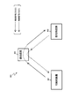
- FIG. 1 shows an example of the satellite communication system 100 according to the present embodiment.
- the portable station device 101 functions as a master station device corresponding to the control station device and the base station device of the normal VSAT system
- the portable station device 102 is a slave station corresponding to the VSAT earth station device of the normal VSAT system. It is a device.
- the portable station device 101 of the master station device and the portable station device 102 of the slave station device construct a private network by PP communication or P-MP communication, and do not have an operation system by a control station device or the like.
- the satellite communication system 100 has a configuration. For example, in the satellite communication system 100 of FIG.
- the slave station device (portable station device 102) is a master station synchronized with a control signal transmitted from the master station device (portable station device 101) via the communication satellite 103. Communicate with the device. Even when there are a plurality of slave station devices similar to the portable station device 102, communication can be performed under the control of the master station device in the same manner.
- the satellite communication system 100 includes a plurality of portable earth station devices (in FIG. 1, the portable station device 101 and the portable station device 102), and is used as long as it can be captured by the communication satellite 103. Because it can be done, it is effective for securing communication in the event of a disaster. However, when the control signal cannot be transmitted / received to / from the base station device due to a wide-area large-scale disaster or the like, it is necessary to adjust the antenna direction with respect to the target communication satellite 103 at the start of operation using only the beacon signal.
- FIG. 2 shows an example of a normal satellite communication system 800.
- the satellite communication system 800 includes a portable station device 801 and a base station device 802 and a communication satellite 803, and a control signal (CSCO signal) is constantly transmitted from the base station device 802.
- CSCO signal control signal
- a plurality of portable station devices can be used.
- One portable station device itself (portable station device 101 in FIG. 1) operates a base station device or a control station device as a master station device, and controls the control with the portable station device 102 that operates as a slave station device. Signals can be sent and received to establish synchronization, and communication signals can be sent and received between the master station device and the slave station device.
- the portable station device 101 which operates as a master station device in a wide-area large-scale disaster or the like, receives a beacon signal of a predetermined frequency transmitted from a communication satellite 103 during operation and adjusts the antenna direction.
- the beacon frequencies overlap in a plurality of communication satellites, there is a problem that the communication satellite cannot be identified. Therefore, satellite information regarding the longitudes and beacon signals of the plurality of communication satellites is retained in advance, and the information is stored. Based on the longitude of the target communication satellite acquired from and the installation location of the own device, the antenna direction with respect to the target communication satellite is calculated, and the antenna direction of the own device is roughly adjusted.
- the frequencies of the beacon signals of a plurality of communication satellites are measured while increasing or decreasing the azimuth angle with the coarsely adjusted azimuth angle of the antenna as a reference direction.
- the reference direction is the target. It is determined that this is the azimuth angle of the antenna with respect to the communication satellite 103.
- the antenna direction is adjusted to the reference direction, and the antenna direction is finely adjusted so that the reception level of the beacon signal to be received is maximized.
- the beacon signal is a CW (Continuous Wave) signal having a predetermined frequency.
- the beacon frequencies are duplicated in a plurality of communication satellites. Even in this case, the antenna direction can be adjusted accurately only by the beacon signal.
- the portable station device 102 that operates as a slave station device is transmitted by the portable station device 101 of the master station device instead of the base station device 802, similarly to the normal portable station device 801 described with reference to FIG.
- the control signal CSCO signal
- the final confirmation of the target communication satellite 103 and the antenna direction can be performed.
- FIG. 3 shows an example of arrangement of a plurality of communication satellites.
- a portable station device 101 is installed on the ground in Japan, and eight communication satellites from a plurality of communication satellites 113 (1) to communication satellites 113 (7) including the communication satellite 103 to be captured are displayed. It is located above the south direction in different east longitude directions. It is assumed that each communication satellite is a geostationary satellite.
- the communication satellite 113 (1) is in the direction of A degree east longitude, the frequency of V polarization is AHz, and the frequency of H polarization is DHz.
- the communication satellite 113 (2) is in the direction of B degree east longitude, the frequency of V polarization is BHz, and the frequency of H polarization is CHz.
- the communication satellite 113 (3) is in the direction of C degrees east longitude, the frequency of V polarization is CHz, and the frequency of H polarization is AHz.
- the target communication satellite 103 to be captured is in the direction of D degree east longitude, the frequency of V polarization is AHz, and the frequency of H polarization is BHz.
- the communication satellite 113 (4) is in the direction of E degree east longitude, the frequency of V polarization is DHz, and the frequency of H polarization is CHz.
- the communication satellite 113 (5) is in the direction of F degrees east longitude, the frequency of V polarization is BHz, and the frequency of H polarization is AHz.
- the communication satellite 113 (6) is in the direction of G degree east longitude, the frequency of V polarization is CHz, and the frequency of H polarization is DHz.
- the communication satellite 113 (7) is in the direction of H degree east longitude, the frequency of V polarization is DHz, and the frequency of H polarization is AHz.
- the portable station device 101 receives a beacon signal whose V polarization frequency is AHz and H polarization frequency. If is BHz, it can be determined that the antenna is pointing in the direction of the target communication satellite. However, if there are multiple communication satellites with beacon signals of the same frequency, there is a possibility of misidentification.
- the satellite communication system 100 information on the directions (east longitude) of a plurality of other communication satellites around the target communication satellite 103 and the frequencies of the V-polarized and H-polarized beacon signals is transmitted to the satellites. It is stored in advance as information, the frequency of each polarization of the beacon signals of the surrounding communication satellites 113 (1) to 113 (7) including the target communication satellite 103 is measured, and the target communication satellite 103 is used as a reference position. It is confirmed that the target communication satellite 103 is obtained by checking whether or not the relative position with the surrounding communication satellite 113 matches the satellite information. As a result, even when there are a plurality of communication satellites having overlapping frequencies, the direction of the antenna can be accurately directed to the target communication satellite 103.
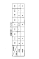
- FIG. 4 shows an example of the satellite information table 151.
- the satellite information table 151 satellite information of a plurality of communication satellites described with reference to FIG. 3 is registered in advance.
- the plurality of communication satellites shown in FIG. 3 and the plurality of communication satellites shown in FIG. 4 do not necessarily correspond to each other.
- the satellite information table 151 shows the east longitude (degrees), the frequency of H polarization (Hz) of the beacon signal, and the frequency of V polarization (Hz) for each satellite.
- the column direction indicates the east longitude
- the direction of the east longitude X degree is set as the direction (reference direction) of the target communication satellite 103, and the directions decrease by 2 degrees, X-2 and X-4.
- X-6, X-8, and four tables of X + 2, X + 4, X + 6, and X + 8 in the direction of increasing by 2 degrees are shown in a total of nine directions.
- the row direction indicates the frequency of H polarization (Hz) and the frequency of V polarization (Hz).
- FIG. 4 shows an example in which communication satellites are located in each of the five directions of east longitude (X-8, X-6, X, X + 4, X + 8).
- X-8, X-6, X, X + 4, X + 8 For example, when the target communication satellite 103 is located in the direction of X degrees east longitude, it can be seen from the satellite information table 151 that the frequency of H polarization of the target communication satellite 103 is AHz and the frequency of V polarization is BHz.
- the satellite communication system 100 includes the orbits of the other plurality of communication satellites 113 in the orbits around the target communication satellite 103 and the frequencies of the V-polarized and H-polarized beacon signals, respectively. Is measured, the measurement result is compared with the information in the satellite information table 151, and the target communication satellite 103 to be captured is confirmed by checking whether the relative position between the target communication satellite 103 and the surrounding communication satellites 113 is correct. can do.
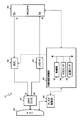
- FIG. 5 shows a configuration example of the portable station device 101 (master station device).
- the portable station device 101 includes an antenna (ANT) 200, a partial demultiplexer (OMT (V / H)) 201, a transmission / reception demultiplexer (TX / RX) 202, a transmitter (BUC) 203, and a low noise amplifier (LNB). It has a -V) 204, a low noise amplifier (LNB-H) 205, a distributor (DIV) 206, a modulator / demodulator (MODEM) 207, an antenna drive unit 208, and an automatic capture control unit 209.
- FIG. 5 shows an example in which the transmission system has V polarization and the reception system has H polarization in opposite directions.
- the polarization in the facing direction is polarization with respect to the traveling direction of the radio wave, and in the present embodiment, the V polarization of the radio wave transmitted from the portable station device 101 to the communication satellite 103 is in the facing direction.
- the radio waves transmitted from the communication satellite 103 to the portable station device 101 have H polarization in the opposite direction.
- the ANT 200 is an antenna such as a parabolic dish, has an antenna drive mechanism for adjusting the direction by controlling the antenna drive unit 208, and transmits and receives radio waves to and from the communication satellite 103.
- ANT is an abbreviation for ANTenna.
- the OMT (V / H) 201 is a demultiplexer that separates a V-polarized signal and an H-polarized signal, and functions in both transmission and reception. For example, the signal received by the ANT200 is output to the TX / RX202 and the LNB-V204, and the signal transmitted from the TX / RX202 is output to the ANT200.
- OMT is an abbreviation for Ortho Mode Transducer.
- TX / RX202 is a transmission / reception demultiplexer that separates a transmission signal and a reception signal.
- BUC203 is a transmitter that integrates, for example, a function of frequency-converting a 1.2 GHz band signal output by MODEM 207 into a 14 GHz band and a high power amplification function.
- BUC is an abbreviation for Block Up Converter.
- the LNB-V204 is a low-noise amplifier that has a function of amplifying a V-polarized 12 GHz band signal received by the ANT200 with low noise and further converting the frequency to, for example, a 1.2 GHz band.
- LNB is an abbreviation for Low Noise Block converter.
- the LNB-H205 is a low-noise amplifier that has a function of amplifying an H-polarized 12 GHz band signal received by the ANT200 with low noise and further converting the frequency to, for example, a 1.2 GHz band.
- DIV206 is a distributor that divides the input signal into two and outputs it. DIV is an abbreviation for DIVider.
- MODEM 207 is a modulation / demodulation device, for example, which modulates and transmits a data signal at a communication speed of 384 kbit / s, receives a modulated signal at a communication speed of 1.5 Mbit / s, and demodulates the data signal.
- MODEM is an abbreviation for MOdulator-DE Modulator.
- the antenna drive unit 208 operates the antenna drive mechanism of the ANT 200 based on the command of the automatic capture control unit 209, and adjusts the three directions of the azimuth angle, the elevation angle, and the polarization angle.
- the azimuth is the angle from true north to the east (corresponding to longitude) about the antenna
- the elevation angle is the angle from the horizontal plane to the upper side
- the polarization angle is the angle between the horizontal plane and the polarization plane of the incoming radio wave.
- the automatic acquisition control unit 209 has a computer function for executing a program stored in advance by the control unit 301, and executes automatic acquisition of the communication satellite 103 and adjustment confirmation during operation.
- the automatic capture control unit 209 controls the transmission level of the BUC 203 of the portable station device 101, controls the modulation / demodulation process of the MODEM 207, controls the antenna drive unit 208, and the like.
- the automatic acquisition control unit 209 includes a control unit 301, a direction sensor 302, a position sensor 303, MON-H304, MON-V305, and a satellite DB 306.
- the control unit 301 operates based on a program stored in advance, and cooperates with each unit of the direction sensor 302, the position sensor 303, the MON-H304, the MON-V305, and the satellite DB306, and the antenna direction by the antenna drive unit 208. And carry out UAT.
- the control unit 301 also adjusts the transmission level of the BUC 203 and controls the MODEM 207 (transmission of CW, designation of modulation / demodulation method, etc.).
- the azimuth sensor 302 is a sensor that measures the azimuth angle of the ANT 200.
- the azimuth sensor 302 measures the current azimuth angle of the ANT 200 obtained from the antenna driving unit 208 based on the information obtained from the compass or the like.
- the azimuth corresponds to longitude.
- the position sensor 303 is a sensor that measures the installation location (latitude / longitude) of the portable station device 101.
- GPS Global Positioning System
- the position sensor 303 is a sensor that measures the installation location (latitude / longitude) of the portable station device 101.
- GPS Global Positioning System
- the MON-H304 is composed of a measuring device (for example, a spectrum analyzer) capable of measuring the reception level and frequency, and measures the reception level and frequency of the H-polarized signal output from the DIV 206.
- a measuring device for example, a spectrum analyzer
- the MON-V305 is composed of a measuring instrument (for example, a spectrum analyzer) capable of measuring the reception level and frequency, and obtains the reception level and frequency of the V-polarized signal output from the LNB-V204. taking measurement.
- a measuring instrument for example, a spectrum analyzer
- MON-H304 and MON-V305 correspond to the measuring unit.
- Satellite DB306 is a database composed of storage media such as a hard disk and memory (corresponding to a storage unit). For example, as satellite information of a plurality of communication satellites including the communication satellite 103, the satellite information table 151 described with reference to FIG. 4 is provided, and position information (east longitude, etc.) and beacon signal information (polarization, frequency, etc.) of each satellite are provided. Etc. are remembered.
- the control unit 301 measures the frequency of H polarization monitored by MON-H304 and the frequency of V polarization monitored by MON-V305, and refers to the satellite DB306. , The east longitude X degree obtained by calculation is roughly adjusted as a reference direction, and it is confirmed whether or not the beacon signal received in the coarsely adjusted reference direction is the beacon signal of the target communication satellite. For example, in the case of FIG. 4 described above, if the frequency of H polarization monitored by MON-H304 is AHz and the frequency of V polarization monitored by MON-V305 is BHz in the reference direction, the coarsely adjusted reference direction Can be determined to be in the direction of the target communication satellite 103.
- the antenna drive unit 208 moves the antenna direction by -4 degrees to set a new reference direction, thereby roughly adjusting the direction of the target communication satellite 103. be able to. Then, in the present embodiment, the control unit 301 finely adjusts the three directions of the azimuth angle, the elevation angle, and the polarization angle of the ANT 200 so that the reception level in the roughly adjusted reference direction is maximized.
- the portable station device 101 can adjust the direction of the antenna only by the beacon signal and automatically capture the target communication satellite 103.
- FIG. 6 shows a configuration example of the portable station device 102 (slave station device).
- the portable station device 102 of the slave station device includes an antenna (ANT) 400, a demultiplexer (OMT (V / H)) 401, a transmitter (BUC) 402, a low noise amplifier (LNB-H) 403, and a modulation / demodulation device. It has (MODEM) 404, an antenna drive unit 405, and an automatic capture control unit 406.
- FIG. 6 shows an example in which the transmission system has V polarization and the reception system has H polarization in the opposite direction.
- the portable station device 102 has the same configuration as the normal portable station device 801 and communicates with the base station device 802 to establish synchronization and transmits / receives communication signals.
- the base station device 802 does not function due to a wide area disaster or the like, it is connected to another portable station device (in this embodiment, the portable station device 101) that operates as a master station device instead of the base station device 802. It is possible to communicate control signals to establish synchronization and send and receive communication signals.
- the ANT400, OMT (V / H) 401, BUC402, LNB-H403, MODEM404 and the antenna drive unit 405 are the ANT200, OMT (V / H) 201, BUC203, LNB-H205, MODEM207 described with reference to FIG. And has the same function as the antenna drive unit 208.
- the automatic capture control unit 406 includes a control unit 501, a direction sensor 502, and a position sensor 503.
- the directional sensor 502 and the position sensor 503 have the same functions as the directional sensor 302 and the position sensor 303 of the automatic capture control unit 209 described with reference to FIG.
- the control unit 501 stores the direction of the ANT 400 in the satellite DB 306 based on the installation location (latitude and longitude) of the ANT 400 acquired from the position sensor 503 and the current direction (longitudinal) of the ANT 400 acquired from the azimuth sensor 502.
- the three directions of the azimuth angle, elevation angle, and polarization angle of the ANT 400 to be adjusted are calculated so as to be the direction of the target communication satellite (communication satellite 103), and the direction of the ANT 400 is adjusted by the antenna driving unit 405.
- the control unit 501 receives a control signal (CSCO signal) from the portable station device 101 of the master station device via MODEM 404, and establishes synchronization.
- CSCO signal control signal
- the portable station device 102 of the slave station device establishes the adjustment of the antenna direction and the synchronization with the portable station device 101 of the master station device, and the portable station device 101 or another portable station. Communication with the device is possible.
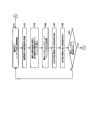
- FIG. 7 shows an example of coarse adjustment processing in the antenna direction.
- the process of FIG. 7 is executed by a program stored in advance in the control unit 301 of the automatic capture control unit 209 of the portable station device 101 shown in FIG.
- step S101 the user of the portable station device 101 turns on the power of the device and starts adjusting the antenna direction. Specifically, after the power is turned on, the user instructs the control unit 301 to start adjusting the antenna direction by using the operation interface (operation buttons, operation panel, etc. (not shown)) of the automatic capture control unit 209 of FIG. , The control unit 301 adjusts the antenna direction and starts the process of capturing the target communication satellite 103.
- the operation interface operation buttons, operation panel, etc. (not shown) of the automatic capture control unit 209 of FIG.
- step S102 the control unit 301 acquires the latitude and longitude of the installation location. Specifically, in the automatic capture control unit 209 of FIG. 5, the control unit 301 measures the latitude and longitude of the installation location of its own device by the position sensor 303.
- step S103 the control unit 301 calculates the azimuth angle, elevation angle, and polarization angle from the longitude of the target communication satellite 103 and the latitude and longitude of the installation location.
- the azimuth is referred to as AZ (AZimuth)
- the elevation angle is referred to as EL (ELevation)
- the polarization angle is referred to as POL (POLarization).
- the control unit 301 aims at the installation location of the portable station device 101 based on the east longitude of the target communication satellite 103 acquired from the satellite DB 306 and the latitude and longitude of the own device measured in step S102.
- the direction (AZ, EL and POL) of the communication satellite 103 is calculated.
- step S104 the control unit 301 roughly adjusts the antenna direction by the AZ, EL, and POL calculated in step S103.
- the control unit 301 is controlled by the antenna drive unit 208 so that the three directions of the ANT 200 in the AZ direction, the EL direction, and the POL direction are the AZ, EL, and POL calculated in step S103, respectively.
- the antenna drive unit 208 has, for example, a three-axis drive device capable of independently adjusting the three directions of AZ, EL, and POL.
- step S105 the control unit 301 measures the frequency (referred to as BCN frequency) of the H-polarized beacon signal in the facing direction. Specifically, the control unit 301 measures the frequency of the H-polarized BCN signal received via the ANT200, OMT201, LNB-H205 and DIV206 with the MON-H304.
- BCN frequency the frequency of the H-polarized beacon signal received via the ANT200, OMT201, LNB-H205 and DIV206 with the MON-H304.
- step S106 the control unit 301 measures the BCN frequency of the V-polarized wave in the opposite direction. Specifically, the control unit 301 measures the frequency of the V-polarized BCN signal received via the ANT200, OMT201, TX / RX202, and LNB-V204 with the MON-V305.
- step S107 the control unit 301 determines whether or not both the BCN frequencies of the H polarization and the V polarization measured in step S105 and step S106 are correct, and if they are not correct, the process returns to step S101 and the same is true. If it is correct, the fine adjustment process described later is performed (shift to the process of (A) in FIG. 8). Specifically, in the control unit 301, the measured BCN frequencies of the H-polarized light and the V-polarized wave are the H-polarized wave of the target communication satellite 103 whose BCN frequency is listed in the satellite information table 151 of the satellite DB 306 described with reference to FIG. It is determined whether or not the frequency matches the frequency of V polarization.
- the satellite communication system 100 can roughly adjust the direction of the antenna in the direction of the target communication satellite 103.
- FIG. 8 shows an example of fine adjustment processing in the antenna direction.
- the process of FIG. 8 is executed by a program stored in advance in the control unit 301 of the automatic capture control unit 209 of the portable station device 101 shown in FIG.
- (A) and (B) shown in FIG. 8 are connected to (A) and (B) of the same name shown in FIG. 7, respectively.
- the process proceeds to step S108 of step 8.
- the process proceeds to the process of step S101 of FIG.
- step S109 the control unit 301 initially sets the AZ direction to (X-8 + 2i) degrees.
- the AZ direction is set to east longitude (X-8) degrees, and each time the counter i is counted up one by one, it is twice. Increased, east longitude (X-6) degrees, east longitude (X-4) degrees, east longitude (X-2) degrees, east longitude (X) degrees, east longitude (X + 2) degrees, east longitude (X + 4) degrees, east longitude (X + 6) degrees ,
- the AZ direction of the antenna changes, such as east longitude (X + 8) degrees.
- step S110 the control unit 301 measures the BCN frequency of the H-polarized wave or the V-polarized wave corresponding to the facing direction or the opposite direction, respectively. Specifically, the control unit 301 measures the frequency of the H-polarized BCN signal with the MON-H304 as in step S105 of FIG. 7, and also measures the V-polarized BCN signal as in step S106 of FIG. The frequency is measured with MON-V305. The control unit 301 makes measurements for each counter i (for each east longitude) and saves each measurement result for each east longitude.
- step S111 the control unit 301 determines whether or not the counter i is 8 or more (i ⁇ 8), proceeds to the process of step S113 if i ⁇ 8, and proceeds to step S112 if i ⁇ 8. Proceed to processing.
- the range from the east longitude (X-8) degrees to the east longitude (X + 8) degrees of the satellite information table 151 shown in FIG. 4 is described. It may be in the range of X-10) degrees to east longitude (X + 10) degrees, or from east longitude (X-6) degrees to east longitude (X + 6) degrees. Further, it does not have to be increased or decreased by 2 degrees, and the angle ranges in the + direction and the-direction may be asymmetric.
- step S109 the antenna direction is set to the direction in which the antenna direction is increased by 2 degrees east longitude.
- step S113 the control unit 301 determines whether or not the measurement results of the H-polarized BCN frequency and the V-polarized BCN frequency for each east longitude saved in step S110 are correct. Specifically, the control unit 301 measures the orbits of a plurality of other communication satellites 113 in the peripheral orbit including the target communication satellite 103 and the frequencies of the V-polarized and H-polarized beacon signals, respectively. By comparing with the information in the satellite information table 151, it is determined whether or not the relative positions of the target communication satellite 103 and the surrounding communication satellites 113 are correct. If the determination is correct, the control unit 301 proceeds to the process of step S114 because the reference direction is the direction of the target communication satellite 103. If the determination is incorrect, the reference direction is not the direction of the target communication satellite 103. The process proceeds to (B) of FIG. 7 corresponding to (B) of 8, and returns to step S101 of the rough adjustment process. Then, the rough adjustment process is executed again.
- step S114 the control unit 301 finely adjusts the AZ direction, the EL direction, and the POL direction in accordance with the X degree east longitude of the reference direction in the AZ direction. Specifically, the control unit 301 measures the reception level of the H-polarized BCN signal with the MON-H304, and measures the reception level of the V-polarized BCN signal with the MON-V305, while the reception level peaks.
- the antenna drive unit 208 is controlled so as to be (maximum), and each direction of the ANT 200 in the AZ direction, the EL direction, and the POL direction is gradually moved back and forth to make fine adjustments.
- step S115 the control unit 301 completes the adjustment of the antenna direction.
- the satellite communication system 100 can direct the antenna in the direction of the target communication satellite 103 by making fine adjustments after the rough adjustment of the antenna direction.
- the satellite communication system 100 according to the present embodiment determines whether or not the position of the target communication satellite 103 with respect to other communication satellites in the vicinity is correct, there are other communication satellites having overlapping BCN frequencies. Even in this case, the target communication satellite 103 can be captured only by the beacon signal, and the direction of the antenna can be adjusted in the direction of the communication satellite 103.
- the program corresponding to the processing described with reference to FIGS. 7 and 8 may be executed on the computer.
- the program may be recorded on a storage medium and provided, or may be provided through a network.
- the antenna direction adjustment method, the portable station device, and the antenna direction adjustment program in the satellite communication system according to the present invention are used for wide-area large-scale disaster in the adjustment of the antenna direction based on the beacon signal. Even if the control signal of the base station device cannot be used due to such reasons, the antenna direction can be accurately adjusted only by the beacon signal.
- a plurality of portable station devices communicate via a communication satellite, but as a form via communication, in addition to the communication satellite, in a radiocon helicopter (drone) or a stratospheric platform. It may be an unmanned aerial vehicle.
- 100 100 ... Satellite communication system; 101 ... Portable station device (master station device); 102 ... Portable station device (slave station device); 103 ... Communication satellite; 151 ... Satellite information table 200,400 ... ANT; 201,401 ... OMT; 202 ... TX / RX; 203,402 ... BUC; 204 ... LNB-V; 205,403 ... LNB-H 206 ... DIV; 207,404 ... MODEM; 208,405 ... Antenna drive unit; 209,406 ... Automatic capture control unit; 301,501 ... Control unit; 302,502 ... Orientation sensor; 303,503 ... Position sensor; 304 ... MON-H; 305 ... MON-V; 306 ... Satellite DB; 800 ... Satellite communication system; 801 ... Portable Station equipment; 802 ... Base station equipment; 803 ... Communication satellite; 151 ... Satellite information table 200,400 ... ANT; 201,401 ... O
Landscapes
- Engineering & Computer Science (AREA)
- Computer Networks & Wireless Communication (AREA)
- Signal Processing (AREA)
- Physics & Mathematics (AREA)
- Astronomy & Astrophysics (AREA)
- Aviation & Aerospace Engineering (AREA)
- General Physics & Mathematics (AREA)
- Radio Relay Systems (AREA)
- Variable-Direction Aerials And Aerial Arrays (AREA)
Abstract
La présente invention concerne un dispositif de station portable qui exécute : un processus de réglage approximatif consistant à conserver des informations de satellite concernant les longitudes d'une pluralité de satellites de communication ainsi qu'un signal de balise puis à calculer, sur la base de la longitude d'un satellite de communication souhaité acquise à partir d'informations de satellite et de la position d'installation du dispositif local, d'une direction d'antenne pour le satellite de communication souhaité, et enfin à régler approximativement la direction d'antenne du dispositif local par rapport à la direction d'antenne calculée ; et un processus de réglage précis consistant à mesurer le signal de balise tout en augmentant/réduisant l'angle d'azimut à l'aide de l'angle d'azimut de l'antenne réglée approximativement en tant que direction de référence lorsque la fréquence du signal de balise est égale à la fréquence prédéfinie du satellite de communication souhaité, et à régler précisément la direction d'antenne en changeant l'angle d'azimut de l'antenne de manière à ajuster la direction de référence de telle sorte que le niveau de réception de signal de balise devient maximal lorsque le résultat de mesure de signal de balise correspond aux informations relatives au signal de balise d'un autre satellite de communication à ladite longitude conservée dans les informations de satellite. Ainsi, il est possible d'ajuster avec précision la direction d'antenne en utilisant uniquement le signal de balise.
Priority Applications (3)
| Application Number | Priority Date | Filing Date | Title |
|---|---|---|---|
| PCT/JP2020/014705 WO2021199218A1 (fr) | 2020-03-30 | 2020-03-30 | Procédé de réglage de direction d'antenne, dispositif de station portable et programme de réglage de direction d'antenne dans un système de communication par satellite |
| US17/914,917 US20230115735A1 (en) | 2020-03-30 | 2020-03-30 | Antenna direction adjusting method, portable station device and antenna direction adjusting program in satellite communication system |
| JP2022512947A JP7318806B2 (ja) | 2020-03-30 | 2020-03-30 | 衛星通信システムにおけるアンテナ方向調整方法、可搬局装置およびアンテナ方向調整プログラム |
Applications Claiming Priority (1)
| Application Number | Priority Date | Filing Date | Title |
|---|---|---|---|
| PCT/JP2020/014705 WO2021199218A1 (fr) | 2020-03-30 | 2020-03-30 | Procédé de réglage de direction d'antenne, dispositif de station portable et programme de réglage de direction d'antenne dans un système de communication par satellite |
Publications (1)
| Publication Number | Publication Date |
|---|---|
| WO2021199218A1 true WO2021199218A1 (fr) | 2021-10-07 |
Family
ID=77928188
Family Applications (1)
| Application Number | Title | Priority Date | Filing Date |
|---|---|---|---|
| PCT/JP2020/014705 WO2021199218A1 (fr) | 2020-03-30 | 2020-03-30 | Procédé de réglage de direction d'antenne, dispositif de station portable et programme de réglage de direction d'antenne dans un système de communication par satellite |
Country Status (3)
| Country | Link |
|---|---|
| US (1) | US20230115735A1 (fr) |
| JP (1) | JP7318806B2 (fr) |
| WO (1) | WO2021199218A1 (fr) |
Cited By (4)
| Publication number | Priority date | Publication date | Assignee | Title |
|---|---|---|---|---|
| CN114301517A (zh) * | 2021-12-30 | 2022-04-08 | 中国电信股份有限公司卫星通信分公司 | 一种基于现有Ku卫星便携站高通量转接控制方法 |
| CN114710818A (zh) * | 2022-03-22 | 2022-07-05 | 北京爱科迪通信技术股份有限公司 | 一种卫星站、卫星系统以及寻星方法 |
| US11391849B2 (en) * | 2017-04-28 | 2022-07-19 | Kabushiki Kaisha Toshiba | Satellite signal acquiring apparatus and method |
| CN116366131A (zh) * | 2023-03-22 | 2023-06-30 | 中国电信股份有限公司卫星通信分公司 | 移动终端与卫星通信的调整方法、装置及系统 |
Citations (4)
| Publication number | Priority date | Publication date | Assignee | Title |
|---|---|---|---|---|
| US20020050953A1 (en) * | 2000-09-29 | 2002-05-02 | Hughes Electronics Corporation | Post-installation monitoring method for a satellite terminal antenna |
| US6724737B1 (en) * | 1999-06-17 | 2004-04-20 | Lockheed Martin Global Telecommunications, Inc | System for controlling communications between a terminal and satellite and method therefore |
| JP2012175217A (ja) * | 2011-02-18 | 2012-09-10 | Nippon Telegr & Teleph Corp <Ntt> | 衛星通信回線制御システムおよび衛星通信回線制御方法 |
| JP5592983B1 (ja) * | 2013-08-13 | 2014-09-17 | スカパーJsat株式会社 | 自動交差偏波識別度測定システム |
-
2020
- 2020-03-30 US US17/914,917 patent/US20230115735A1/en active Pending
- 2020-03-30 WO PCT/JP2020/014705 patent/WO2021199218A1/fr active Application Filing
- 2020-03-30 JP JP2022512947A patent/JP7318806B2/ja active Active
Patent Citations (4)
| Publication number | Priority date | Publication date | Assignee | Title |
|---|---|---|---|---|
| US6724737B1 (en) * | 1999-06-17 | 2004-04-20 | Lockheed Martin Global Telecommunications, Inc | System for controlling communications between a terminal and satellite and method therefore |
| US20020050953A1 (en) * | 2000-09-29 | 2002-05-02 | Hughes Electronics Corporation | Post-installation monitoring method for a satellite terminal antenna |
| JP2012175217A (ja) * | 2011-02-18 | 2012-09-10 | Nippon Telegr & Teleph Corp <Ntt> | 衛星通信回線制御システムおよび衛星通信回線制御方法 |
| JP5592983B1 (ja) * | 2013-08-13 | 2014-09-17 | スカパーJsat株式会社 | 自動交差偏波識別度測定システム |
Cited By (4)
| Publication number | Priority date | Publication date | Assignee | Title |
|---|---|---|---|---|
| US11391849B2 (en) * | 2017-04-28 | 2022-07-19 | Kabushiki Kaisha Toshiba | Satellite signal acquiring apparatus and method |
| CN114301517A (zh) * | 2021-12-30 | 2022-04-08 | 中国电信股份有限公司卫星通信分公司 | 一种基于现有Ku卫星便携站高通量转接控制方法 |
| CN114710818A (zh) * | 2022-03-22 | 2022-07-05 | 北京爱科迪通信技术股份有限公司 | 一种卫星站、卫星系统以及寻星方法 |
| CN116366131A (zh) * | 2023-03-22 | 2023-06-30 | 中国电信股份有限公司卫星通信分公司 | 移动终端与卫星通信的调整方法、装置及系统 |
Also Published As
| Publication number | Publication date |
|---|---|
| JP7318806B2 (ja) | 2023-08-01 |
| JPWO2021199218A1 (fr) | 2021-10-07 |
| US20230115735A1 (en) | 2023-04-13 |
Similar Documents
| Publication | Publication Date | Title |
|---|---|---|
| WO2021199218A1 (fr) | Procédé de réglage de direction d'antenne, dispositif de station portable et programme de réglage de direction d'antenne dans un système de communication par satellite | |
| EP3353906B1 (fr) | Acquisition de satellites en orbite terrestre basse (leo) sans boussole | |
| CN108140943B (zh) | 低成本卫星用户终端天线 | |
| EP3278472B1 (fr) | Procédé et appareil permettant d'éviter un dépassement de limites de brouillage pour un système à satellites non géostationnaires | |
| US10578749B2 (en) | GNSS antenna with an integrated antenna element and additional information sources | |
| US20210006327A1 (en) | Method and apparatus for establishing communications with a satellite | |
| US5784028A (en) | Method and apparatus for simplex delivery of signals to obstructed geographical areas | |
| AU731834B2 (en) | Wireless communication device and system incorporating location-determining means | |
| CN110687561A (zh) | 一种隐蔽卫星导航定位系统 | |
| EP2955856B1 (fr) | Procede de recherche et de suivi d'un signal d'interet a partir d'un satellite et d'un indicateur rssi a bande etroite | |
| US7456783B2 (en) | GPS signal repeater and GPS receiver of stationary orbit satellite, and method for positioning stationary orbit satellite using the same | |
| US20080218427A1 (en) | Multiple mode RF communication system | |
| US7123895B2 (en) | Method and system for implementing a communications transceiver using modified GPS user equipment | |
| WO2021199217A1 (fr) | Procédé pour confirmer une onde radio transmise dans un système de communication par satellite, dispositif de station portable et programme de confirmation d'onde radio transmise | |
| WO2021250821A1 (fr) | Procédé de réglage de direction d'antenne, dispositif de station portable et programme de réglage de direction d'antenne dans un système de communication par satellite | |
| JPH10332413A (ja) | 衛星ナビゲーションシステムを確立するための方法 | |
| RU2214054C2 (ru) | Устройство и способ повторного использования полосы частот спутникового вещания для сигналов наземного вещания | |
| US6643509B1 (en) | Civil aviation communication system | |
| JP3732151B2 (ja) | 車載中継局の衛星捕捉システム及び車載中継局の衛星捕捉方法 | |
| US20230262596A1 (en) | Determining the transmission power for a mobile device | |
| CN113964476B (zh) | 一种动中通天线系统和载体 | |
| JPH09247124A (ja) | 無線通信路リンクアップシステム | |
| JPH07209408A (ja) | 静止衛星のgpsオーバーレイシステム | |
| Cheng | Exploring the use of signals of opportunity for practical localization | |
| KR20150130118A (ko) | 안테나 제어 장치 |
Legal Events
| Date | Code | Title | Description |
|---|---|---|---|
| 121 | Ep: the epo has been informed by wipo that ep was designated in this application |
Ref document number: 20929244 Country of ref document: EP Kind code of ref document: A1 |
|
| ENP | Entry into the national phase |
Ref document number: 2022512947 Country of ref document: JP Kind code of ref document: A |
|
| NENP | Non-entry into the national phase |
Ref country code: DE |
|
| 122 | Ep: pct application non-entry in european phase |
Ref document number: 20929244 Country of ref document: EP Kind code of ref document: A1 |