WO2021193648A1 - Image processing device and server - Google Patents
Image processing device and server Download PDFInfo
- Publication number
- WO2021193648A1 WO2021193648A1 PCT/JP2021/012026 JP2021012026W WO2021193648A1 WO 2021193648 A1 WO2021193648 A1 WO 2021193648A1 JP 2021012026 W JP2021012026 W JP 2021012026W WO 2021193648 A1 WO2021193648 A1 WO 2021193648A1
- Authority
- WO
- WIPO (PCT)
- Prior art keywords
- super
- image
- unit
- resolution
- resolution processing
- Prior art date
Links
Images


Classifications
-
- G—PHYSICS
- G06—COMPUTING; CALCULATING OR COUNTING
- G06T—IMAGE DATA PROCESSING OR GENERATION, IN GENERAL
- G06T3/00—Geometric image transformation in the plane of the image
- G06T3/40—Scaling the whole image or part thereof
- G06T3/4053—Super resolution, i.e. output image resolution higher than sensor resolution
-
- A—HUMAN NECESSITIES
- A63—SPORTS; GAMES; AMUSEMENTS
- A63F—CARD, BOARD, OR ROULETTE GAMES; INDOOR GAMES USING SMALL MOVING PLAYING BODIES; VIDEO GAMES; GAMES NOT OTHERWISE PROVIDED FOR
- A63F13/00—Video games, i.e. games using an electronically generated display having two or more dimensions
- A63F13/30—Interconnection arrangements between game servers and game devices; Interconnection arrangements between game devices; Interconnection arrangements between game servers
- A63F13/35—Details of game servers
-
- A—HUMAN NECESSITIES
- A63—SPORTS; GAMES; AMUSEMENTS
- A63F—CARD, BOARD, OR ROULETTE GAMES; INDOOR GAMES USING SMALL MOVING PLAYING BODIES; VIDEO GAMES; GAMES NOT OTHERWISE PROVIDED FOR
- A63F13/00—Video games, i.e. games using an electronically generated display having two or more dimensions
- A63F13/45—Controlling the progress of the video game
- A63F13/49—Saving the game status; Pausing or ending the game
-
- H—ELECTRICITY
- H04—ELECTRIC COMMUNICATION TECHNIQUE
- H04N—PICTORIAL COMMUNICATION, e.g. TELEVISION
- H04N19/00—Methods or arrangements for coding, decoding, compressing or decompressing digital video signals
- H04N19/10—Methods or arrangements for coding, decoding, compressing or decompressing digital video signals using adaptive coding
- H04N19/169—Methods or arrangements for coding, decoding, compressing or decompressing digital video signals using adaptive coding characterised by the coding unit, i.e. the structural portion or semantic portion of the video signal being the object or the subject of the adaptive coding
- H04N19/17—Methods or arrangements for coding, decoding, compressing or decompressing digital video signals using adaptive coding characterised by the coding unit, i.e. the structural portion or semantic portion of the video signal being the object or the subject of the adaptive coding the unit being an image region, e.g. an object
- H04N19/172—Methods or arrangements for coding, decoding, compressing or decompressing digital video signals using adaptive coding characterised by the coding unit, i.e. the structural portion or semantic portion of the video signal being the object or the subject of the adaptive coding the unit being an image region, e.g. an object the region being a picture, frame or field
-
- H—ELECTRICITY
- H04—ELECTRIC COMMUNICATION TECHNIQUE
- H04N—PICTORIAL COMMUNICATION, e.g. TELEVISION
- H04N7/00—Television systems
- H04N7/01—Conversion of standards, e.g. involving analogue television standards or digital television standards processed at pixel level
Definitions
- This disclosure relates to data processing technology, especially image processing equipment and servers.
- the game application is executed on the server and the game scene image is drawn.
- the server provides the drawn game scene image to the client terminal via the network.
- the client terminal displays the game scene image provided by the server.
- the video quality may deteriorate due to lossy compression coding and the resolution may be reduced.
- the resolution and the corresponding color space of the display provided in the client terminal may be higher than the resolution and the color space of the game scene image provided by the server. In such a case, it is conceivable that the client terminal executes super-resolution processing in order to improve the quality of the game scene image viewed by the user.
- This disclosure has been made in view of these issues, and one purpose is to provide a technique for processing super-resolution with low delay.
- the image processing apparatus of a certain aspect of the present disclosure includes an acquisition unit that acquires moving image data in units of partial images smaller than one frame, and a sub-image acquired by the acquisition unit as a unit. It includes a super-resolution processing unit that executes resolution processing, and a display control unit that sequentially outputs partial images that have undergone super-resolution processing by the super-resolution processing unit to the display unit.
- This server has an image generation unit that generates a moving image of an application in frame units, a compression coding unit that compresses and encodes an image generated by the image generation unit in units of partial images smaller than one frame, and compression coding. It includes a transmission unit that transmits the partial image to a client terminal that executes super-resolution processing in units of the partial image.
- super-resolution can be processed with low delay.
- Super resolution Video quality enhancement
- image processing including high definition of an image and restoration or reconstruction of high frequency components.
- a game application is executed on a server and a game scene image is drawn.
- the game scene image is provided to the client terminal via the network.
- the user watches the game scene via the client terminal and inputs the game.
- Data related to user input is transferred to the server via the network and reflected in the progress of the game application. If this series of processes takes a long time, the arrival of the game scene image on the client terminal is delayed, and it becomes difficult for the user to play the game in real time. Therefore, it is required to reduce the delay of the entire processing system.
- the game scene image is, for example, a video image such as 60 fps (frames per second) of an FHD (Full HD) image (1920 ⁇ 1080 pixels) or 60 fps of a 4K image (3840 ⁇ 2160 pixels). Compression coding is required to transmit game scene images in a finite network band (for example, 10 Mbps or 30 Mbps).
- the image quality of the game scene image may be deteriorated due to lossy compression coding, or the resolution may be reduced (downscaling). Further, the resolution and the corresponding color space of the display displayed on the client terminal may be higher than the resolution and the color space of the game scene image transmitted from the server. Therefore, in order to improve the quality of the game scene image viewed by the user, it is conceivable to execute the super-resolution processing on the client terminal provided with the game scene image.
- the present disclosure proposes a technology for realizing super-resolution processing with low delay in a cloud game and a technology for realizing super-resolution processing based on scene information in a cloud game. do.
- the super-resolution processing unit processes partial images (hereinafter, also referred to as “slices”), and outputs the processing results to the display control unit in the same or smaller particle size.
- the video compression coding unit / decoding / decompression unit processes a partial image (slice) unit and outputs the decompression result image in a partial image (slice) unit
- the super-resolution processing unit is a subsequent process.
- the same partial image (slice) is processed, and the processing result is output to the display control unit in the same or smaller particle size.
- the super-resolution processing unit executes the processing in the basic unit or the unit of an integral multiple that matches the basic unit in the video compression coding process.
- the super-resolution processing unit processes partial images (slices) in units.
- a memory for holding data in partial image units is provided between the video decoding / extension unit and the super-resolution processing unit in the previous stage.
- a memory for holding data in units of partial images is provided between the display control unit and the super-resolution processing unit in the subsequent stage.
- the super-resolution processing unit executes flow control in units of partial images between the video decoding and extension unit and the display control unit.
- the super-resolution processing unit executes scene analysis or scene information integration processing, image resolution raising processing (upscaling), image filtering processing, image restoration / reconstruction processing, etc., these individual processes are performed. Is executed in units of partial images. When the unit particle size in the internal processing of the super-resolution processing unit is multiplied by an integer, it becomes a partial image unit.
- the super-resolution processing unit uses deep learning in the super-resolution processing, it has a plurality of inference processing units so that it can be switched and used at any time. As a result, when it is necessary to dynamically apply a different deep learning model (database that holds the learning result) to the inference processing unit based on the scene analysis result, it is possible to hide the time required for setting initialization.
- the input image is converted into a plurality of low resolutions by using pyramid scaling, and the scene analysis is executed in order from the low resolution image.
- the scene analysis is executed in a small area sampled at the original resolution from the discrete positions of the input image.
- This solution method is also a method of processing super-resolution based on scene information in a cloud game.
- the super-resolution processing unit acquires scene information as a hint from the previous stage processing and uses it in the super-resolution processing.
- the scene information used in the super-resolution processing on the client terminal is acquired in advance on the server and transmitted to the client terminal.
- the scene information used in the super-resolution processing on the client terminal is acquired by the server in parallel with the compression coding and transmitted to the client terminal.
- the scene information used in the super-resolution processing on the client terminal is analyzed by the server in parallel with the compression coding and transmitted to the client terminal.
- the scene information used in the super-resolution processing on the client terminal is acquired from the game application on the server and transmitted to the client terminal.
- the scene information used in the super-resolution processing in the client terminal is acquired from the scene analysis result used in the compression coding in the server and transmitted to the client terminal.
- the scene information used in the super-resolution processing in the client terminal is acquired from the configuration result of the compression coding processing used by the decoding / decompression unit.
- the super-resolution processing unit of the client terminal executes super-resolution processing using the scene information acquired from the server or the decoding / decompression unit.
- the super-resolution processing unit of the client terminal omits or simplifies the scene analysis performed by itself by using the scene information acquired from the server or the decoding / decompression unit.
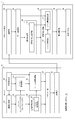
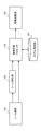
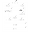
- FIG. 1 is a block diagram showing a configuration of the information processing system 10 of the embodiment.
- the information processing system 10 includes a server 12 and a client terminal 14.
- the server 12 is an information processing device that executes an application (a game application in the embodiment).
- the client terminal 14 is an image processing device (also called an information processing device, for example, a stationary game machine) that displays an image (for example, a game scene image) of an application executed on the server 12.
- the server 12 and the client terminal 14 are connected via a communication network including LAN, WAN, the Internet, and the like.
- the server 12 includes a content determination unit 20, an image generation unit 22, a buffer 24 (rendering buffer and frame buffer), a compression coding unit 28, a scene analysis unit B26, a scene information acquisition unit 32, a packetization unit 34, and a communication unit 36. Be prepared.
- the compression coding unit 28 includes a scene analysis unit A30.
- the client terminal 14 includes a communication unit 40, a data acquisition unit 42, a decoding / decompression unit 44, a super-resolution processing unit 48, a display control unit 54, and a display panel 56.
- the decoding / extension unit 44 includes a coding method acquisition unit 46.
- the super-resolution processing unit 48 includes a scene analysis unit C50 and a scene information integration unit 52.
- Each block shown in the block diagram of the present disclosure can be realized by an element such as a computer CPU / memory or a mechanical device in terms of hardware, and can be realized by a computer program or the like in terms of software. , Draws a functional block realized by their cooperation. Those skilled in the art will understand that these functional blocks can be realized in various forms by combining hardware and software.
- the content determination unit 20 of the server 12 is mainly realized by the CPU, executes a game application, and determines the content to be drawn.
- the image generation unit 22 of the server 12 is realized mainly by the GPU, and draws a frame of a moving image of the game application based on the processing result of the game application (for example, data related to the content to be drawn) by the content determination unit 20 (for example, the frame of the moving image of the game application). In other words, generate).
- the image generation unit 22 stores the frame of the drawing result in the buffer 24 (frame buffer).
- the buffer 24 (rendering buffer) of the server 12 stores the intermediate result of the drawing process by the image generation unit 22.
- the compression coding unit 28 of the server 12 compresses and encodes the data of the image (frame) stored in the buffer 24 (frame buffer) in units of partial images smaller than one frame.
- the compression coding unit 28 may perform lossy compression.
- the partial image is an image of each region formed by dividing the image plane of the frame into a predetermined size. That is, the partial image is, for example, an image of each region formed by dividing the image plane by a boundary line set in the horizontal direction, the vertical direction, the vertical / horizontal bidirectional direction, or the diagonal direction.
- the compression coding unit 28 may internally generate an I frame and a P frame, and the partial image smaller than the above one frame may be a partial image of the I frame or a partial image of the P frame. good.
- the compression coding unit 28 outputs the data of the partial image after compression coding to the packetization unit 34.
- the scene analysis unit A30 of the compression coding unit 28 executes the scene analysis process originally performed for compression coding.
- the scene analysis unit A30 executes a scene analysis process to obtain an intra analysis result (plane similarity), an inter analysis result (motion vector), a CU (Coding Unit) allocation examination result, and a scene segmentation result.
- the result of the scene analysis process by the scene analysis unit A30 includes an analysis result that cannot be determined only by referring to the compressed coded data.
- the result of the scene analysis process of the embodiment may include identification information of the image to be analyzed that can identify the image to be analyzed (partial image in the embodiment). The same applies to the following scene analysis results and scene information.
- the scene analysis unit B26 of the server 12 refers to the image (frame) data stored in the buffer 24 (frame buffer) and executes the scene analysis process originally required for the super-resolution process.
- the scene analysis unit B26 hides the processing time by executing the scene analysis process in parallel with the compression coding process by the compression coding unit 28. Further, the scene analysis unit B26 also obtains the drawing content of the game application stored in the buffer 24 (frame buffer) as a hint of the super-resolution processing in the scene analysis processing.
- the scene analysis unit B26 may further acquire the drawing contents of the application or OS other than the game application stored in the buffer 24 (frame buffer) as a hint of the super-resolution processing.
- the hint of super-resolution processing is, for example, what kind of image the menu UI and subtitles drawn by the game application or OS are, what kind of shape they are, and what kind of image coordinate position they are drawn. It is information such as whether it is done.
- This information is information about an image in which an image of additional content such as a menu UI and subtitles is combined (overlaid) with an image of the main content (character, etc. in the case of a game) of the application, and is additional.
- Information (table, etc.) regarding an ⁇ (alpha) value indicating what kind of image coordinate position, what kind of transparency, and what kind of transparency the content is combined with the image of the main content may be included.
- the scene information acquisition unit 32 of the server 12 acquires the result of the scene analysis process by the scene analysis unit A30 and the result of the scene analysis process by the scene analysis unit B26. Further, the scene information acquisition unit 32 acquires information indicating the scene content to be drawn with respect to the game application from the content determination unit 20.
- the information indicating the scene content may include, for example, the arrangement state of the 3D object, the texture characteristics used, and the scene segmentation information.
- the scene information acquisition unit 32 includes scene information including the result of the scene analysis processing by the scene analysis unit A30, the result of the scene analysis processing by the scene analysis unit B26, and the information indicating the scene content obtained from the content determination unit 20.
- first scene information it is also referred to as “first scene information” to be output to the packetizing unit 34.
- the packetization unit 34 of the server 12 packetizes the data of the partially image after compression coding output from the compression coding unit 28 and the first scene information output from the scene information acquisition unit 32, and packetizes the communication unit 36. Output to.
- the communication unit 36 of the server 12 transmits the packet data output from the packetization unit 34 to the client terminal 14 via the communication network.
- the packetizing unit 34 and the communication unit 36 of the server 12 can be said to be transmission units that transmit data to the client terminal 14.
- the communication unit 40 of the client terminal 14 receives the packet data transmitted from the server 12 via the communication network.
- the data acquisition unit 42 of the client terminal 14 acquires (reconstructs) the compressed coded partial image data and the first scene information based on the packet data received by the communication unit 40.
- the data acquisition unit 42 outputs the compressed and encoded partial image data to the decoding / decompression unit 44, and outputs the first scene information to the scene information integration unit 52.
- the decoding / decompression unit 44 of the client terminal 14 executes a decoding / decompression process on the data of the compression-encoded partial image to obtain the original partial image.
- the decoding / stretching unit 44 outputs the partial image after the decoding / stretching to the super-resolution processing unit 48.
- the coding method acquisition unit 46 of the decoding / stretching unit 44 obtains scene information (hereinafter, also referred to as “second scene information”) included in the data of the compression-encoded partial image.
- the coding method acquisition unit 46 acquires the second scene information regarding the partial image to be decoded and decompressed from the information indicating the configuration of the compression coding process in the server 12 used in the decoding / decompression processing (which can be said to be the configuration result). do.
- the second scene information includes a frame type (type of I frame, P frame, etc.), a quantization parameter (QP) value, a motion vector, and CU allocation information.
- the coding method acquisition unit 46 outputs the second scene information to the scene information integration unit 52.
- the super-resolution processing unit 48 of the client terminal 14 executes super-resolution processing (for example, high resolution and high image quality) on the partial image input from the decoding / extension unit 44.
- the super-resolution processing unit 48 may be realized by the CPU and / or GPU executing a computer program in which the logic of super-resolution processing is implemented.
- the scene analysis unit C50 of the super-resolution processing unit 48 executes a scene analysis process as a pre-stage process of the super-resolution process using a known technique. Specifically, the scene analysis unit C50 analyzes a partial image deteriorated by compression coding and / or resolution reduction. The scene analysis unit C50 may further execute the same scene analysis process as the scene analysis unit B26 of the server 12. The scene analysis unit C50 outputs the result of the scene analysis process to the scene information integration unit 52 as the third scene information.
- the scene information integration unit 52 integrates a plurality of types of scene information indicating the characteristics of a specific partial image. Specifically, the scene information integration unit 52 has input the first scene information input from the data acquisition unit 42, the second scene information input from the coding method acquisition unit 46, and the scene analysis unit C50. By integrating the third scene information based on the image identification information included in each scene information, the scene information (integrated scene information) of the specific partial image is acquired. Note that any one of the first scene information, the second scene information, and the third scene information may be missing, and the scene information integration unit 52 inputs the first scene information, the second scene information, and the third scene information. The scene information that has been created may be integrated.
- the super-resolution processing unit 48 executes super-resolution processing on the input partial image based on the scene information corresponding to the partial image integrated by the scene information integration unit 52. Specific examples of super-resolution processing will be described later.
- the display control unit 54 of the client terminal 14 sequentially outputs and displays a plurality of partial images that have undergone super-resolution processing by the super-resolution processing unit 48 on the display panel 56.
- the data acquisition unit 42 of the client terminal 14 acquires the moving image data to be displayed on the display panel 56 in units of partial images smaller than one frame.
- the super-resolution processing unit 48 of the client terminal 14 executes super-resolution processing in units of partial images acquired by the data acquisition unit 42.
- the display control unit 54 of the client terminal 14 sequentially outputs the partial images that have undergone super-resolution processing by the super-resolution processing unit 48 to the display panel 56. According to the client terminal 14 of the embodiment, the delay of the super-resolution processing can be suppressed.
- the super-resolution processing unit 48 of the client terminal 14 executes super-resolution processing on the input image based on the scene information indicating the characteristics of the image.
- the display control unit 54 of the client terminal 14 outputs an image that has undergone super-resolution processing by the super-resolution processing unit 48 to the display panel 56.
- the above scene information is acquired in advance in the pre-stage processing until the super-resolution processing is performed on the image to be the super-resolution processing (for example, the first scene information to the third scene information).
- the client terminal 14 of the embodiment by grasping what kind of scene it is in advance, the super-resolution processing most suitable for the scene is selected and executed while suppressing the processing time of the super-resolution processing unit. This makes it possible to suppress the delay in super-resolution processing while improving the image quality.
- the image generation unit 22 of the server 12 generates a moving image of the application in frame units.
- the compression coding unit 28 of the server 12 compresses and encodes an image (for example, a game scene image) generated by the image generation unit 22 in units of partial images smaller than one frame.
- the transmission unit (for example, the packetization unit 34 and the communication unit 36) of the server 12 transmits the compressed coded partial image to the client terminal 14 that executes the super-resolution processing in units of the partial image. According to the server 12 of the embodiment, the delay of the super-resolution processing in the client terminal 14 can be suppressed.
- the image generation unit 22 of the server 12 generates an image of the application.
- the scene information acquisition unit 32 of the server 12 acquires scene information (for example, first scene information) indicating the features of the image generated by the image generation unit.
- the transmission unit of the server 12 transmits the image data and the scene information to the client terminal 14, so that the client terminal 14 executes the super-resolution processing for the image based on the scene information.
- efficient super-resolution processing can be performed at the client terminal 14, and delay in the super-resolution processing at the client terminal 14 can be suppressed.
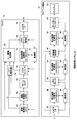
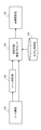
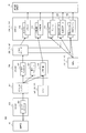
- FIG. 2 is also a block diagram showing the configuration of the information processing system 10 of the embodiment.
- the same functional blocks as the functional blocks of the information processing system 10 of FIG. 1 are designated by the same reference numerals.
- the drawing control unit 60 of the server 12 of FIG. 2 corresponds to the content determination unit 20 of FIG.
- the image drawing unit 62 of the server 12 of FIG. 2 corresponds to the image generation unit 22 of FIG.
- the frame buffer 64 of the server 12 of FIG. 2 corresponds to the buffer 24 of FIG.
- the video encoder 66 of the server 12 of FIG. 2 corresponds to the compression coding unit 28 of FIG.
- the video stream control unit 68 of the server 12 of FIG. 2 corresponds to the packetization unit 34 of FIG.
- the input / output I / F 70 of the server 12 of FIG. 2 corresponds to the communication unit 36 of FIG.
- the server 12 further includes a partial image storage unit 72 and a control unit 74.
- the partial image storage unit 72 stores the data of the partial image after compression coding output from the video encoder 66.
- the control unit 74 may be realized by the CPU, controls the start and end of processing in each functional block, controls the synchronization of processing between functional blocks, and controls the transmission and reception of data between functional blocks. (Flow control).
- the input / output I / F 80 of the client terminal 14 of FIG. 2 corresponds to the communication unit 40 and the data acquisition unit 42 of FIG.
- the video decoder 82 of the client terminal 14 of FIG. 2 corresponds to the decoding / extension unit 44 of FIG.
- the display controller 84 of the client terminal 14 of FIG. 2 corresponds to the display control unit 54 of FIG.
- the display 86 of the client terminal 14 of FIG. 2 corresponds to the display panel 56 of FIG.
- the client terminal 14 further includes a partial image storage unit 88, a partial image storage unit 90, a partial image storage unit 92, and a control unit 94.
- the partial image storage unit 88 stores the data of the partial image acquired by the input / output I / F 80 (in other words, transmitted from the server 12).
- the partial image storage unit 90 stores the data of the partial image after the decoding and decompression by the video decoder 82.
- the partial image storage unit 92 stores the data of the partial image after the super-resolution processing by the super-resolution processing unit 48.
- the control unit 94 controls the start and end of processing in each functional block, controls the synchronization of processing between functional blocks, and controls the transmission and reception of data between functional blocks (flow control).
- the client terminal 14 may further include an image processing unit.
- the image processing unit includes (1) composition processing of a plurality of planes, (2) color space conversion processing, and (3) resolution conversion processing relating to the partial image stored in the partial image storage unit 90 or the partial image storage unit 92. At least one may be performed.
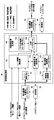
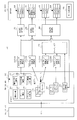
- FIG. 3 is a block diagram showing a detailed configuration of the super-resolution processing unit 48 of FIG.
- the super-resolution processing unit 48 includes a scene analysis unit C50, a scene information integration unit 52, a resolution conversion unit 100, a partial image storage unit 102, a super-resolution image generation unit 104, and a super-resolution processing control unit 110.
- the super-resolution processing control unit 110 transmits a control signal to other functional blocks in the super-resolution processing unit 48, and performs synchronization control, timing control, and flow control.
- the resolution conversion unit 100 converts the resolution of the partial image after decoding and decompression output from the video decoder 82. Specifically, the resolution conversion unit 100 increases the resolution of the partial image by a known method such as interpolation, and stores the increased resolution partial image in the partial image storage unit 102.
- the super-resolution image generation unit 104 reads out the partial image stored in the partial image storage unit 102, filters the read partial image, and executes image restoration / reconstruction processing to obtain the partial image. Increase image quality.
- the super-resolution image generation unit 104 includes a model holding unit 106 and a DNN (Deep Neural Network) accelerator 108.
- the model holding unit 106 is a model for super-resolution processing, and stores a model generated by deep learning described later in relation to FIG.
- the model may be, for example, a calculation formula or a function in which an algorithm for super-resolution processing (for example, image filtering processing, image restoration / reconstruction processing, etc.) is implemented.
- the DNN accelerator 108 reads out the partial image whose resolution has been increased by the resolution conversion unit 100 from the partial image storage unit 102, and improves the image quality of the read partial image based on the model stored in the model holding unit 106.
- the DNN accelerator 108 outputs a high-quality partial image to the partial image storage unit 92.
- the model holding unit 106 may store a model generated by machine learning, which will be described later in relation to FIG.
- the resolution conversion unit 100 may execute the resolution conversion process by referring to at least one of the first scene information, the second scene information, and the third scene information from the scene analysis unit C50.
- the resolution conversion unit 100 may be provided after the super-resolution image generation unit 104, that is, the resolution conversion unit 100 has a high resolution of the partial image whose high image quality has been improved by the super-resolution image generation unit 104. It may be converted.
- the super-resolution processing unit 48 may have a configuration that does not include the resolution conversion unit 100, that is, a configuration that does not execute the resolution conversion processing.
- the super-resolution processing unit 48 may not include the resolution conversion unit 100, and the super-resolution image generation unit 104 may be configured to simultaneously execute the image quality improvement of the partial image and the resolution conversion processing.
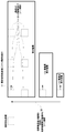
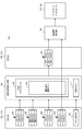
- FIG. 4 schematically shows a method of reducing the delay of the scene analysis process.
- the super-resolution processing unit 48 includes scene analysis processing, scene information integration processing, image resolution increase processing (upscaling), image filter processing, and image restoration / reconstruction processing. Etc. are executed.
- the super-resolution processing unit 48 executes these individual internal processes in units of partial images. It is desirable that the unit particle size in the internal processing of the super-resolution processing unit 48 is configured to be a partial image unit when multiplied by an integer.
- the unit particle size in the internal processing is indicated by a dotted square (hereinafter, also referred to as “analysis unit particle size”).
- the super-resolution processing unit 48 converts the input image into a plurality of low-resolution partial images by using pyramid scaling in the scene analysis (scene analysis unit C50). Then, the super-resolution processing unit 48 executes the scene analysis processing in the order of the partial image having a relatively low resolution to the partial image having a relatively high resolution.
- the super-resolution processing unit 48 (scene analysis unit C50) sequentially transfers the scene analysis results for each of the partial images having a plurality of resolutions to the scene information integration unit 52 without waiting for the completion of the analysis of all the partial images having different resolutions. Output.
- the super-resolution image generation unit 104 can start the super-resolution image generation process as soon as possible.
- the super-resolution image generation unit 104 notifies the scene analysis unit C50 of that fact.
- the scene analysis unit C50 terminates the scene analysis process for the high-resolution partial image, in other words, ends the process even during the process.
- the scene analysis unit C50 may continue the scene analysis process for the higher resolution partial image, and the analysis result is obtained. It may be supplemented and provided to the super-resolution image generation unit 104.
- the super-resolution processing unit 48 (scene analysis unit C50) performs a small area (for example, an analysis unit) sampled at the original resolution from the discrete positions of the input image in the scene analysis. Multiple images of the particle size area) are extracted. This extraction process may be executed according to the following policy. That is, at least one of the following policies (a) to (d) may be adopted in the allocation of the discrete “area of analysis unit particle size”. (A) As shown in FIG. 11 described later, the CU allocation information is used to allocate one analysis unit particle size region per CU.
- an image region having a relatively high score may be assigned a region having an analysis unit particle size in preference to an image region having a relatively low score. Further, the image region having a higher score may be preferentially assigned to the analysis unit particle size region. The preferential allocation or preferential allocation may be to allocate a relatively large number of "analysis unit particle size regions".
- the total number of allocations may be larger than the initial value, or may be larger than the total number of allocations for frames other than the I frame.
- the super-resolution processing unit 48 when the input partial image is an I frame, the analysis unit particle size of the entire partial image is larger than that when the input partial image is other than the I frame.
- the number of allocated areas may be increased.
- the super-resolution processing unit 48 (scene analysis unit C50) executes scene analysis only on the extracted images of a plurality of small areas. According to the configurations shown in FIGS. 4 (1) to (3), the load of scene analysis can be reduced, and the processing time can be suppressed.
- FIG. 5 schematically shows machine learning-based super-resolution processing.
- the source image 122 is an image before super-resolution processing, and is an image having relatively low resolution and image quality (partial image in the embodiment).
- the high-quality image 128 is an image after super-resolution processing, and is an image having relatively low resolution and image quality (partial image in the embodiment).
- the model holding unit 120 corresponds to the model holding unit 106 of FIG.
- the model holding unit 120 stores, for example, a model created by offline machine learning.
- the offline machine learning and the model created by the learning may have at least one of the following features (a) to (e).
- (A) Perform learning offline and in advance.
- (B) In learning, "high-definition image of image quality that the super-resolution processing result should aim for” and "scene analysis result in the high-definition image” are used as teacher data.
- (C) In learning and inference (that is, generation of a high-quality image using a machine learning processor or a deep learning processor), a "scene analysis result" is also input.
- the learning convergence of the model is improved, the accuracy of the model is improved, the bloat of the model and the increase in the inference processing time are suppressed, and more accurate super-resolution processing can be performed. It will be possible.
- the first scene information and the second scene information are used for scene analysis, and the feature amount which is the result of the scene analysis is used for learning and inference of super-resolution processing. This makes it possible to reproduce the image quality before the deterioration of the image quality due to the lossy compression coding, the reduction of the resolution, the reduction of the color space, and the like.
- the scene information itself may be input to learning and inference to aim for the same effect.
- the scene analysis unit 124 corresponds to the scene analysis unit A30, the scene analysis unit B26, the scene analysis unit C50, and the scene information integration unit 52 in FIG.
- the scene analysis unit 124 calculates the feature amount of the source image 122, and based on the feature amount, sets a local subblock larger than the conventional super-resolution into one of a plurality of categories (for example, thousands of categories). It may be classified.
- the scene analysis unit 124 may classify the source image 122 (content reflected therein) into the sky, clouds, face, desert, or mechanical structure.
- the above-mentioned feature amount may include a feature amount for detecting an unfavorable side effect (noise, etc.) associated with image compression.
- the machine learning processor 126 corresponds to the DNN accelerator 108 in FIG.
- the machine learning processor 126 executes image conversion processing and reconstruction processing based on the result of scene analysis by the scene analysis unit 124.
- the machine learning processor 126 may perform various filtering and resolution conversions for antialiasing, sharpness, denoising, and contrast enhancement.
- the machine learning processor 126 may change parameters for various filters, transformations, and reconstructions for each classified subblock region.
- the processing particle size may be a frame for detecting an object, or a partial image smaller than the frame. Further, a set of algorithms and parameters created in advance by human or machine learning may be prepared, and the machine learning processor 126 may select a set of algorithms and parameters suitable for the scene analysis result. Some algorithms may use a temporal approach for motion vector detection and 3D digital noise reduction (3DNR).
- 3DNR 3D digital noise reduction
- FIG. 6 schematically shows deep learning-based super-resolution processing.
- the model holding unit 130 corresponds to the model holding unit 106 of FIG.
- the model holding unit 130 stores, for example, a DNN model created by offline deep learning.
- the DNN model created by offline deep learning and its learning is among the features (a) to (e) of the model created by offline machine learning and its learning described in connection with FIG. It may have at least one.
- the scene analysis unit 132 corresponds to the scene analysis unit A30, the scene analysis unit B26, the scene analysis unit C50, and the scene information integration unit 52 in FIG.
- the scene analysis unit 132 may calculate the feature amount of the source image 122 and classify the local subblock into one of a plurality of categories (for example, thousands of categories) based on the feature amount.
- the scene analysis unit 132 may classify the source image 122 (content reflected therein) into the sky, clouds, face, desert, or mechanical structure.
- the above-mentioned feature amount may include a feature amount for detecting an unfavorable side effect (noise, etc.) associated with image compression.
- the deep learning inference processor 134 corresponds to the DNN accelerator 108 in FIG.
- the deep learning inference processor 134 executes image conversion processing and reconstruction processing based on the result of scene analysis by the scene analysis unit 132.
- the deep learning inference processor 134 typically uses a DNN model for scene classification and image transformation / reconstruction.
- the deep learning inference processor 134 may use a DNN model in combination with another algorithm (for example, a human-based scene analysis algorithm or a super-resolution algorithm).
- the deep learning inference processor 134 may perform various filtering processes for antialiasing, sharpness, denoising, and contrast enhancement.
- the deep learning inference processor 134 may change parameters for various filters, transformations, and reconstructions for each classified subblock region.
- the trained DNN model is optimized for integer-based inference accelerators, even if it is trained on a floating-point basis.
- the processing particle size may be a frame for detecting an object, or a partial image smaller than the frame.
- Some algorithms may use a temporal approach for motion vector detection and 3DNR.
- the super-resolution image generation unit 104 of the super-resolution processing unit 48 executes super-resolution processing on a partial image based on the scene information corresponding to the partial image.
- the super-resolution image generation unit 104 of the super-resolution processing unit 48 uses scene information to dynamically switch the processing for high-definition of an image according to an image area (that is, the content reflected in a partial image). ..
- an example of processing by the super-resolution image generation unit 104 will be described.
- the image generation unit 104 minimizes the amount of execution of the sharpness-based image conversion process. In other words, the super-resolution image generation unit 104 reduces the amount of execution of the sharpness-based image conversion process as compared with the case where the image area is flat as a picture and the content does not change much.
- the effect of sharpness processing is large. Therefore, the artificial filtering result is conspicuous, in other words, the adverse effect of the artificial filtering is conspicuous.
- the super-resolution image generation unit 104 When the image area to be processed has high-density and intermittent changes as a picture (for example, a picture in which a bird's-eye view of a forest is viewed from a distance), the super-resolution image generation unit 104 performs sharpness-based image conversion processing. Do it positively. In other words, the super-resolution image generation unit 104 increases the amount of execution of the sharpness-based image conversion process as compared with the case where the image area does not have high-density and intermittent changes as a picture. This is because when the image area has a high density and intermittent changes as a picture, the effect of the sharpness processing is less likely to appear, and the adverse effect of the artificial filter processing is less noticeable.
- the super-resolution image generation unit 104 Suppresses sharpness-based image conversion processing.
- the super-resolution image generation unit 104 may skip the sharpness-based image conversion process. This is because when the image area has contents having clear lines or dots as a picture, the effect of the sharpness processing is weak and the adverse effect of the artificial filter processing is very conspicuous. In such an image region, it is preferable that the super-resolution image generation unit 104 performs a dedicated contour correction process according to the type of line or point.
- the super-resolution image generation unit 104 executes an image conversion process (filter process) specialized for the person.
- a large number of judgment rules and a number of sets of filter processing and conversion processing to be performed on them may be defined as described in the above-mentioned plurality of cases. These pairs may be implemented as tables, databases, and models. Then, various input conditions may be given to these sets, and the results of the filtering process and the conversion process may be learned and optimized. As a result, it is possible to realize a processing system in which the generated contents of the super-resolution image are switched based on the scene information and the input image contents.
- the super-resolution image generation unit 104 may determine the image conversion content (filter processing or conversion processing content) to be executed based only on the scene information (first to third scene information). Further, the super-resolution image generation unit 104 may determine the image conversion content to be executed based on the scene information and the input image (partial image).
- the table, database, or model may be modified depending on which method is used.
- the scene information integration unit 52 outputs scene information for each scene analysis unit particle size (for example, the analysis unit particle size shown in FIG. 4) to the super-resolution image generation unit 104.
- the scene information integration unit 52 may accumulate scene information in the past frame or the past partial image and refer to it when constructing the scene information in the latest frame or the latest partial image.
- the super-resolution image generation unit 104 may proceed with the processing at the same particle size as the scene analysis unit particle size, or may proceed with the processing at a particle size other than that.
- the super-resolution image generation unit 104 may switch the model to be used among the plurality of models stored in the model holding unit 106 based on the scene information. Further, the super-resolution image generation unit 104 may (1) load a plurality of models into the model holding unit 106 in advance in order to hide the model switching time, and (2) activate a plurality of DNN accelerators. Alternatively, (3) at least one of the preloaded model and the pre-launched DNN accelerator may be dynamically switched.
- the model used by the super-resolution image generation unit 104 may be learned and constructed in advance so as to correspond to scene information and input images under various conditions. As a result, the model switching according to the scene information may be suppressed, or the model switching time may be suppressed.
- the super-resolution processing control unit 110 may use an identifier or the like in order to associate the scene information (scene analysis result) with the paired image (partial image).
- FIG. 7 is a conceptual diagram of pipeline processing for each partial image.
- the server 12 generates the moving image frame 140 at a predetermined or variable rate.
- the frame 140 has a configuration in which images for the left eye and an image for the right eye are represented in a region divided into two equal parts on the left and right, but the configuration of the image generated by the server is not limited to this.
- the server 12 compresses and encodes the frame 140 for each partial image.
- the image plane is divided into five in the horizontal direction to form partial images 142a, 142b, 142c, 142d, and 142e.
- the partial images 142a, 142b, 142c, 142d, and 142e are compressed and encoded one after another in this order, and are sequentially transmitted and displayed to the client terminal 14 as shown by the arrows. That is, while the uppermost partial image 142a is subjected to processing such as compression coding, transmission, decoding / decompression, and output to the display panel 56, the lower partial image 142b and the lower partial image 142c are referred to.
- the partial images are sequentially transmitted and displayed as described above. As a result, various processes required from image drawing to display can be performed in parallel, and the display can be advanced with the minimum delay even if the transfer time intervenes.
- FIG. 8 is also a conceptual diagram of pipeline processing for each partial image.
- the figure is a reference to FIG. 6 of a past application by the applicant (Japanese Patent Application No. 2019-21536).
- the figure shows the processing timing from the image generation on the server 12 to the image display on the client terminal 14.
- the processing time of the super-resolution processing unit is added between the decoding / decompression processing and the display processing.
- the processing time of the coding method acquisition unit 46 of the decoding / stretching unit 44 can be concealed by executing this processing as a background processing of the decoding / stretching processing.
- the processing times of the scene analysis unit A30, the scene analysis unit B26, and the scene information acquisition unit 32 are concealed by executing these processes in the background of the compression coding process by the compression coding unit 28. Can be done. Further, the process of outputting the scene information from the data acquisition unit 42 to the scene information integration unit 52 can also be executed as a background process of the decoding / decompression processing by the decoding / decompression unit 44.
- FIG. 9 shows an example of scene information held by the game application.
- the game application in other words, the content determination unit 20 and the image generation unit 22 that execute the game application
- the content determination unit 20 and the image generation unit 22 that execute the game application store these internal data in the buffer 24 (rendering buffer).
- the scene analysis unit A30 and the scene analysis unit B26 may acquire the data of the above (1) to (4) stored in the buffer 24 (rendering buffer) as scene information.
- "Tekari" in the present specification is also referred to as "highlight”.
- the drawing internal data of the application as shown in FIG. 9 is data that exists before the application generates the final drawing result, and is data that is referred to when the application generates the final drawing result.
- scene analysis for example, scene segmentation or the like
- scene analysis is executed in advance with reference to the data of (1) to (4) above.
- the processing delay is reduced and the scene analysis accuracy is improved.
- FIG. 9 for example, the position of a rapidly moving object in the foreground, the position of an object exposed to light, the position where the image is crushed in a dark place (position where it is difficult to identify the object), and the like. You can also get the scene information of.
- FIG. 10 shows an example of scene analysis. At least one of the scene analysis unit A30 of the server 12, the scene analysis unit B26, and the scene analysis unit C50 of the client terminal 14 applies the parameter group and score calculation rule described in Japanese Patent Application No. 2019-179439 and Japanese Patent Application No. 2019-179440. You may use it to perform scene analysis.
- FIG. 10 shows FIGS. 27 to 31 of Japanese Patent Application No. 2019-179439.
- the parameters used for scene analysis may include at least one of the following items.
- Amount of optical flow for example, in which direction the pixel is moving and the speed at which the pixel area is moving.
- Amount of encoded movement (ME) for example, in which direction the rectangular area is moving and the speed at which the rectangular area is moving.
- ME encoded movement
- Particle size of encoded CU allocation for example, size of CU.
- Whether or not to switch scenes for example, whether or not to insert an encoded I frame).
- Image texture type that occupies the screen (edge area, flat area, or High Density / Data / Crowd area, etc.). This texture type is not the texture type used for 3D drawing, but the texture type distributed in the two-dimensional image of the drawing result.
- Harris Corner Amount of feature points and edges (for example, coordinates with feature points and edges, edge strength, etc.).
- Depth data (for example, depth information of each pixel, Z value in a 3D game, etc.)
- Object amount (for example, the amount of an object such as a chair or a car, or the size of the object on the screen). ) Amount of each level of Mipmap texture used in 3D drawing.
- LOD Level of Detail
- Usage of each level of tessellation (12) Amount of letters and symbols.
- Drawing scene type This type includes, for example, menus, settings, loading screens, subjective line-of-sight drawing, bird's-eye view drawing, two-dimensional dot drawing games, three-dimensional drawing games, first-person shooters, racing games, sports games, action games, simulation games. , Adventure novel game.
- the score calculation rule is, for example, (1) a score calculation rule based on the size of an image on an image, and (2) fineness of an object. It may be one of a score calculation rule based on (3) a score calculation rule based on contrast and dynamic range, (4) a score calculation rule based on image movement, and (5) a score calculation rule based on the type of texture. .. Further, the score calculation rule may be (6) a score calculation rule that emphasizes resolution, (7) a score calculation rule that emphasizes frame rate, and (8) a score calculation rule that emphasizes the quantization parameter (QP) value. At least one of the scene analysis unit A30 of the server 12, the scene analysis unit B26, and the scene analysis unit C50 of the client terminal 14 calculates the score for each unit area or each partial image in the internal processing of the super-resolution processing unit 48. You may.
- This parameter may include at least one of a feature quantity obtained from an input video image (eg, a partial image) and a feature quantity obtained during compression coding of the input video image (eg, AVC / HEVC encoder).
- the feature amount obtained from the input video image may include at least one of the following (1) to (5).
- Image texture type edge area, flat area, high Density / Data / Crowd area, etc.
- Harris Corner Amount of feature points and edges for example, coordinates with feature points and edges, edge strength, etc.
- Optical flow for example, in which direction the rectangular area is moving and the speed at which the rectangular area is moving.
- Depth data for example, depth information of each pixel).
- the result of detecting an object by image recognition for example, information on a coordinate area where a chair or a car is located).
- the feature amount obtained at the time of compression coding of the input video image may include at least one of the following (1) to (6).
- Motion Stationion (ME) information for example, in which direction the rectangular area is moving and the speed at which the rectangular area is moving).
- CU allocation information for example, the size of CU.
- Information in the Region of Interest (ROI) area is also called a region of interest or an region of interest, and is, for example, an image region to which a high bit rate is assigned for high image quality.
- QP quantization parameter
- FIG. 11 shows an example of CU allocation information.
- the CU allocation information in the figure shows that the region where the color change is large is assigned a smaller coding unit block.
- the scene analysis unit A30 may detect a region having a large color change based on the CU allocation information, and the scene information acquisition unit 32 generates first scene information indicating a region having a large color change. You may.
- the super-resolution processing unit 48 of the client terminal 14 may execute the super-resolution processing based on the region where the color change of the partial image indicated by the first scene information of the partial image is large.
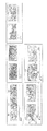
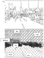
- FIG. 12 shows an example of a scene analysis method.
- the figure shows that scene segmentation extracts the types of objects that appear in an image.
- at least one of the scene analysis unit A30 of the server 12, the scene analysis unit B26, and the scene analysis unit C50 of the client terminal 14 uses a known method such as template matching to obtain the image 144 of FIG. It may be classified into areas such as cars, buildings, roads, and lanes.
- FIG. 13 also shows an example of the scene analysis method.
- At least one of the scene analysis unit A30 of the server 12, the scene analysis unit B26, and the scene analysis unit C50 of the client terminal 14 may execute a known human skin region estimation process to extract the feature amount of the image.
- the shaded area in FIG. 13 indicates a region estimated as human skin.
- the scores of each of the plurality of regions in the input image may be calculated.
- the score calculation rule in the human skin region estimation process may assign a higher score to the region estimated as human skin than the region not estimated as human skin.
- FIG. 14 also shows an example of the scene analysis method.
- FIG. 14 shows an example of detecting video compression noise. Even if at least one of the scene analysis unit A30 of the server 12, the scene analysis unit B26, and the scene analysis unit C50 of the client terminal 14 detects video compression noise from the image and extracts the video compression noise as the feature amount of the image. good.
- the source of this figure is “Local estimation of video compression artifacts” 2011 IEEE International Conference on Consumer Electronics (ICCE).
- the super-resolution image generation unit 104 may refer to the artifact intensity as shown in FIG.
- the artifact intensity can be said to be the intensity of a compressed artifact, and is data indicating the degree of image deterioration (image distortion, etc.) caused by the application of lossy compression.
- the super-resolution image generation unit 104 may increase the strength of the smoothing filter based on the machine learning result in the region where the image deterioration due to noise is severe in the super-resolution processing. For example, the super-resolution image generation unit 104 executes a first intensity smoothing process on a region where the artifact intensity is less than a predetermined threshold value, and a first intensity smoothing process is performed on a region where the artifact intensity is less than the above threshold value. A second intensity smoothing process stronger than the intensity of 1 may be performed. Further, the super-resolution image generation unit 104 may execute a stronger smoothing process in a region having a stronger artifact intensity.
- At least one of the scene analysis unit A30 of the server 12, the scene analysis unit B26, the coding method acquisition unit 46 of the client terminal 14, and the scene analysis unit C50 is (1) whether or not the scene emphasizes user interaction. At least one of the scene information to be shown, (2) the scene information to show the content of the scene or the type of the image, and (3) the scene information to show the current drawing method may be acquired.
- the super-resolution processing unit 48 of the client terminal 14 may execute the super-resolution processing using at least one of the scene information (1) to (3).
- the scene information of (1) may include at least one of the following information.
- (1-1) Information indicating that the drawn content is a movie scene (pre-rendering) that does not require input by a user operation, waiting for loading, or waiting for setup.
- (1-2) Information indicating that the drawn content is a game play scene (real-time rendering) that requires input by a user operation.
- (1-3) Information indicating the frequency of sampling user input when the drawn content is a game play scene that requires user operation input.
- the scene information of (2) may include at least one of the following information.
- the scene information in (3) can be said to be scene information related to the original settings at the time of drawing and the settings in compression coding / transfer.
- the scene information of (3) may include at least one of the following information.
- (3-7) Drawing dynamic range, HDR (High-Dynamic-range Rendering) profile, or tone mapping method.
- HDR High-Dynamic-range Rendering
- tone mapping method For example, in GPU drawing, a mapping method or a calculation method including rounding when dropping a floating-point calculation result into a frame buffer output.
- QP Quantization parameter
- the super-resolution processing unit 48 is the scene information acquired from the game application, and is the scene acquired in the pre-stage processing on the server 12 or the client terminal 14 up to the super-resolution processing. Based on the information, simplification or non-execution of super-resolution processing may be selected. Based on the scene information, the super-resolution processing unit 48 may determine whether to prioritize high image quality by super-resolution processing or low delay.
- the second embodiment will be mainly described with a configuration different from that of the first embodiment, and the description of the common configuration will be omitted as appropriate.
- the components of the second embodiment the components that are the same as or correspond to the components of the first embodiment are designated by the same reference numerals. It goes without saying that the configuration of the second embodiment can be any combination with the configurations of the first embodiment and the modified examples.
- the second embodiment is different from the first embodiment in that the information processing device (game console in the second embodiment) that controls the display of the image also generates an image.
- the game console of the second embodiment corresponds to the client terminal 14 of the first embodiment, but unlike the client terminal 14 of the first embodiment, image generation, image super-resolution processing, and super-resolution image Execute display control by itself.
- the technical idea after the second embodiment is not limited to the game console, and can be applied to various information processing devices that process images.
- FIG. 15 is a block diagram showing the configuration of the game console 200 of the second embodiment.
- the game console 200 includes a content determination unit 20, an image generation unit 22, a buffer 24, a scene analysis unit B26, a scene information acquisition unit 32, a super-resolution processing unit 48, a display control unit 54, and a display panel 56.
- the super-resolution processing unit 48 includes a scene analysis unit C50 and a scene information integration unit 52.
- the game console 200 does not include functions related to compression coding and decoding / decompression among the functions provided by the server 12 and the client terminal 14 of the first embodiment. Since the details of each functional block shown in FIG. 15 have already been explained, the description thereof will be omitted again.
- FIG. 16 and 17 are also block diagrams showing the configuration of the game console 200 of the second embodiment.
- FIG. 16 shows a functional block related to the processing in the previous stage
- FIG. 17 shows a functional block related to the processing following FIG.
- the game console 200 of the second embodiment includes a CPU 201, a GPU 202, a DRAM (Dynamic Random Access Memory) 204, and a super-resolution processing unit 48.
- the super-resolution processing unit 48 includes a scene analysis unit C50, a SRAM (Static Random Access Memory) 206, an adaptive resolution conversion unit 208, a learning parameter table 210, a super-resolution image generation unit 104, and a model holding unit 106.
- the arrangement of the DRAMs and SRAMs shown in the block diagram of the present specification is logical, and the number of physical DRAMs and SRAMs is not limited.
- the plurality of DRAMs and SRAMs in the block diagram may be realized by physically the same DRAMs and SRAMs.
- the DRAM 204 stores various data related to images of game applications.
- the DRAM 204 corresponds to the buffer 24 and the partial image storage unit 90 of the first embodiment. Specifically, the DRAM 204 stores a frame 220, meta information 222, other screen data 224, and a past frame 226.
- the frame 220 is image data generated by the running game application, in other words, video data of the game content.
- the GPU 202 corresponds to the image generation unit 22 and the image drawing unit 62 of the first embodiment. The GPU 202 generates the frame 220 and stores the frame 220 in the DRAM 204.
- the meta information 222 includes scene information (for example, information indicating the drawing content of the frame 220) as an analysis result by the scene analysis unit B26 of the first embodiment, and the scene obtained from the content determination unit 20 of the first embodiment. Includes information (eg, 3D object placement status, used texture characteristics, scene segmentation information).
- the meta information 222 may be generated by one or both of the CPU 201 (content determination unit 20) and the GPU 202. When there is no server, the meta information 222 may include the first scene information obtained from the CPU 201 (content determination unit 20) of the game console 200 or the scene analysis unit B26.
- the other screen data 224 is image data other than the game application in the game console 200.
- the other screen data 224 includes (a) first scene information obtained from the scene analysis unit B26 of the game console 200, (b) drawing internal data of FIG. 9 generated by the image generation unit 22 of the game console 200, and the first. It may include scene information and (c) UI plane 236 and the like described later.
- the other screen data 224 is a general term for these (a) to (c).
- the past frame 226 is the data of the past displayed image of the running game application.
- the past frame 226 may be the frame 220 before the super-resolution processing generated in the past in the frame 220 that continues to be generated intermittently, or the data output from the display interface 248 after the super-resolution processing is not shown. It may be a frame written back to the DRAM in the data path.
- the meta information 222 of the DRAM 204, the other screen data 224, and the past frame 226 are each input to the super-resolution processing unit 48 in slice units.
- the other screen data 224 and the past frame 226 may be input to the scene analysis unit C50 or the adaptive resolution conversion unit 208.
- Image feature information 228, Y slice 230, UV slice 232, and meta information 222 as additional data are generated in SRAM 206 based on other screen data 224 and past frame 226 input to the scene analysis unit C50 and the adaptive resolution conversion unit 208. May be done.
- These additional data generated in the SRAM 206 may be additionally input to the super-resolution image generation unit 104 as needed.
- the scene analysis unit C50 is an optional functional block, refers to the meta information 222 stored in the DRAM 204, and executes a scene analysis process as a pre-stage process of the super-resolution process using a known technique.
- the scene analysis unit C50 may execute the same scene analysis process as the scene analysis unit B26 of the first embodiment.
- the scene analysis unit C50 passes the scene analysis result (scene information) to the adaptive resolution conversion unit 208, and stores the scene analysis result (scene information) in the SRAM 206 as image feature information 228.
- the scene information of the second embodiment may include the same contents as the scene information of the first embodiment, except that the contents related to compression coding and decoding / decompression are excluded.
- the SRAM 206 corresponds to the partial image storage unit 102 of the first embodiment.
- the SRAM 206 stores the image feature information 228, and further stores the Y slice 230, the UV slice 232, and the meta information 222.
- the meta information 222 is transferred from the DRAM 204.
- Third scene information obtained from the scene analysis unit C50 may be added to the meta information 222.
- the Y slice 230 and the UV slice 232 are data relating to a slice (YUV format in the example) which is a partial image of the frame 220.
- the Y slice 230 is data of the Y component of the slice.
- UV slice 232 is data on the UV component of the slice.
- the Y component can be said to be a luminance component or a luminance signal.
- the UV component can be said to be a color difference component, and includes a difference (U) between the luminance signal and the blue component and a difference (V) between the luminance signal and the red component.
- the UV component can also be referred to as a hue component and a saturation component.
- the learning parameter table 210 is a parameter referred to for classifying the contents of a slice into any of a plurality of categories, and is a table that holds parameters created by machine learning.
- the adaptive resolution conversion unit 208 corresponds to the resolution conversion unit 100 of the first embodiment, reads out the data of the frame 220 stored in the DRAM 204 in slice units, and executes adaptive resolution conversion for the read slices.
- the adaptive resolution conversion includes a process of increasing the resolution of the slice, similarly to the resolution conversion unit 100 of the first embodiment.
- the adaptive resolution conversion is a sub-block of a slice (for example, 4 ⁇ 4 pixels or 8 ⁇ ) read from the DRAM 204 based on the scene information input from the scene analysis unit C50 and the parameters stored in the learning parameter table 210.
- the plurality of categories may include tens to hundreds of categories.
- a plurality of categories may include an edge region (for example, a region where the amount of change in pixel value is large), a detailed region (for example, a region where the pixel value changes finely), and a flat region (for example, a region where the amount of change in pixel value is small). good.
- the adaptive resolution conversion unit 208 may apply a filter related to at least one of antialiasing, sharpness, denoising, and contrast enhancement to the subblock of the slice according to the category of the subblock of the slice. For example, a filter that weakens the sharpness may be applied to the subblocks classified into the edge region. Further, a filter for enhancing sharpness may be applied to the subblocks classified into the detail area. Further, a filter that minimizes sharpness may be applied to the subblocks classified into the flat region.
- a filter related to at least one of antialiasing, sharpness, denoising, and contrast enhancement to the subblock of the slice according to the category of the subblock of the slice. For example, a filter that weakens the sharpness may be applied to the subblocks classified into the edge region. Further, a filter for enhancing sharpness may be applied to the subblocks classified into the detail area. Further, a filter that minimizes sharpness may be applied to the subblocks classified into the flat region.
- the adaptive resolution conversion unit 208 stores the Y component of the slice after the adaptive resolution conversion in the SRAM 206 (Y slice 230). Further, the adaptive resolution conversion unit 208 stores the UV component of the slice after the adaptive resolution conversion in the SRAM 206 (UV slice 232).
- the GPU 202 generates the YUV format frame 220, but as a modification, the GPU 202 may generate the RGB format frame 220. In this case, the adaptive resolution conversion unit 208 may convert the RGB format frame 220 into the YUV format and then read the slice data from the converted frame.
- the model holding unit 106 stores a model for super-resolution processing on the Y component of the slice.
- the model holding unit 106 stores a DNN model for scene classification and image conversion / reconstruction.
- the model holding unit 106 may store the DNN model in combination with another algorithm (for example, a human-based scene analysis algorithm or a super-resolution algorithm).
- the super-resolution image generation unit 104 reads the Y slice 230 from the SRAM 206.
- the super-resolution image generation unit 104 performs super-resolution processing (improvement of image quality) on the Y slice 230 based on the image feature information 228 and meta information 222 stored in the SRAM 206 and the model stored in the model holding unit 106. Etc.).
- the super-resolution image generation unit 104 includes a DNN accelerator 108 and a control MCU (MicroControlUnit) 212.
- the control MCU 212 corresponds to the super-resolution processing control unit 110 of the first embodiment.
- the control MCU 212 may execute, for example, strip-shaped image pipeline processing, small-grain DMA (Direct Memory Access) of the super-resolution algorithm, and algorithm switching processing.
- DMA Direct Memory Access
- the super-resolution image generation unit 104 may refer to the other screen data 224 and the past frame 226 stored in the DRAM 204 in the super-resolution processing for the Y slice 230.
- the super-resolution image generation unit 104 refers to the other screen data 224 and the past frame 226 to display the movement of the object drawn on the Y slice 230 to be processed and the noise contained in the Y slice 230 to be processed. It may be detected.
- the super-resolution image generation unit 104 may switch the super-resolution processing algorithm (filter or the like) based on the movement of the object drawn on the Y slice 230. Further, the super-resolution image generation unit 104 may cancel the noise contained in the Y slice 230 in the super-resolution processing.
- the super-resolution image generation unit 104 In the super-resolution image generation unit 104, what kind of image, what kind of shape, and what kind of image coordinate position the menu UI, subtitles, etc. drawn by the game application or OS are drawn. Such information may be acquired from any data (228, 230, 232, 224, 226, etc.) input to the super-resolution image generation unit 104.
- the super-resolution image generation unit 104 may switch the super-resolution processing for the Y slice 230 based on the acquired information. For example, the super-resolution image generation unit 104 may select a super-resolution process in which edges are not easily destroyed based on the learning result of the DNN model as the super-resolution process for the image area of the menu UI or subtitles.
- the super-resolution image generation unit 104 stores the result of super-resolution processing on the Y slice 230 (SR-Y slice 234 described later) in the SRAM 240 described later. On the other hand, the super-resolution image generation unit 104 skips the super-resolution processing for the UV slice 232 stored in the SRAM 206. The UV slice 232 stored in the SRAM 206 is transferred to the SRAM 240 described later without being subjected to super-resolution processing.
- the game console 200 of the second embodiment further includes a SRAM 240, a DRAM 242, a resolution conversion unit 244, an overlay unit 246, and a display interface 248.
- SRAM 240 corresponds to the partial image storage unit 92 of the first embodiment.
- the SRAM 240 stores the SR-Y slice 234 generated by the super-resolution processing unit 48 and the UV slice 232 that is not subject to the super-resolution processing.
- the GPU 202 further generates a UI plane 236 that is an image other than the game content and is an image of the user interface (UI) related to the user's operation.
- the GPU 202 stores the generated UI plane 236 in the DRAM 242.
- the UI plane 236 is a kind of other screen data 224, and includes an image showing various menus of the game generated by the game application and an image for various settings for the game.
- the UI plane 236 includes an image of the UI generated by the OS (Operating System) of the game console 200 independently of the application such as a game.
- the UI generated by the OS includes, for example, an image for switching or terminating an application, an image of a download completion notification, an image showing friend information, and the like.
- the resolution conversion unit 244 may execute the resolution conversion processing for the UI plane 236 so that the resolution is equivalent to the image of the processing result by the adaptive resolution conversion unit 208.
- the overlay unit 246 overlays (in other words, synthesizes) the SR-Y slice 234 and the UV slice 232 stored in the SRAM 240 and the UI plane 236 after the resolution conversion by the resolution conversion unit 244, that is, the image of the game content. Generate one slice image (ie, a partial image) that contains both the UI images.
- the same ID (for example, the same frame ID and slice ID) is assigned to the Y slice 230 and the UV slice 232 extracted from the same frame 220 (slice) and the SR-Y slice 234 after the super-resolution processing.
- NS The time for super-resolution processing on the Y slice 230 corresponding to the UV slice 232 is added to the time for holding the UV slice 232 in the SRAM 240.
- the corresponding Y slice 230 is a Y slice 230 originating from the same slice, in other words, a Y slice 230 having the same ID.
- the overlay portion 246 synthesizes the SR-Y slice 234 and the UV slice 232 to which the same ID is given.
- the buffering amount of the image feature information 228, the Y slice 230, and the meta information 222 in the SRAM 206 is an amount in which the input data required by the super-resolution image generation unit 104 is not interrupted (in other words, an amount that does not cause underflow).
- the buffering amount of the SR-Y slice 234 in the SRAM 240 is an amount in which the input data required by the overlay unit 246 is not interrupted (in other words, an amount that does not cause underflow).
- the buffering amount of the UV slice 232 the super-resolution processing for the Y slice 230 originating from the same slice is completed, and the SR-Y slice 234 and the UV slice 232 originating from the same slice have completed the super-resolution processing.
- the amount of data retained until the timing of coalescing the YUV components at the overlay portion 246 is set. That is, the following equation is established.
- Retention time of Y slice 230 in SRAM 206 + Y slice processing time of super-resolution image generation unit 104 + Retention time of SR-Y slice 234 in SRAM 240 Retention time of UV slice 232 in SRAM 240
- the same slice Synchronous processing is realized by assigning the same ID to the Y slice 230 and the UV slice 232 originating from the above.
- the display interface 248 corresponds to the display controller 84 of the first embodiment.
- the display interface 248 sequentially displays a plurality of slice images sequentially generated by the overlay unit 246 on the display panel 56 (display 86).
- the super-resolution processing is executed in units of slices, and the slices subjected to the super-resolution processing are sequentially displayed.
- the delay of super-resolution processing can be suppressed.
- the game console 200 performs super-resolution processing on the Y component of the slice, but does not perform super-resolution processing on the UV component of the slice. As a result, the amount of calculation and time required for super-resolution processing can be reduced, and the amount of hardware resources of the game console 200 can be reduced.
- the game console 200 does not perform the super-resolution processing on the UI plane 236, and synthesizes the UI plane 236 after the super-resolution processing of the content frame.
- side effects for example, occurrence of jaggy
- the configuration in which the super-resolution processing is performed only on the Y component of the slice described in the second embodiment and the configuration in which the super-resolution processing on the UI plane 236 is avoided are also provided in the client terminal 14 of the first embodiment. Applicable.
- the third embodiment will be mainly described with a configuration different from that of the second embodiment, and the description of the common configuration will be omitted as appropriate.
- the components of the third embodiment the components that are the same as or correspond to the components of the above-described embodiment are designated by the same reference numerals. It goes without saying that the configuration of the third embodiment can be arbitrarily combined with the configurations of other examples and modifications.
- FIG. 18 is a block diagram showing the configuration of the game console of the third embodiment.
- the game console 200 of the third embodiment includes a communication unit 40, a DRAM 252, a demultiplexer 254, a DRAM 256, and a video decoder 258 in addition to the functional blocks included in the game console 200 of the second embodiment shown in FIGS. 16 and 17. Be prepared.
- the drawing of the game application does not have to be completed only on the server, and the game console 200 may execute additional drawing. Further, in the third embodiment, another application or OS different from the game application may execute additional drawing.
- the communication unit 40 receives the video stream 260 streamed from the server 12, and stores the received video stream 260 in the DRAM 252.
- the video stream 260 contains data of slices to be super-resolution processed.
- the video stream 260 includes a video payload 262, an audio payload 264, and a slice 266, which will be described later.
- the communication unit 40 may include communication functions such as Wi-Fi (registered trademark), Gigabit Ethernet (“Ethernet” is a registered trademark), and DMA.
- the communication unit 40 may acquire the video stream 260 via known wireless communication or wired communication. Alternatively, the communication unit 40 may acquire the video storm stored in the predetermined memory by DMA.
- the demultiplexer 254 extracts the video payload 262, the audio payload 264, and the meta information 222 from the video stream 260 stored in the DRAM 252, and stores the extracted video payload 262, the audio payload 264, and the meta information 222 in the DRAM 256.
- the DRAM 256 stores a video payload 262, an audio payload 264, and meta information 222.
- the meta information 222 can be said to be hint information for super-resolution processing, and may include scene information provided from the server 12 to the client terminal 14 in the first embodiment. For example, scene information related to compression coding of slices may be included. It may be included. Further, the meta information 222 may also include the first scene information and the second scene information generated by the server.
- the video decoder 258 corresponds to the decoding / extension unit 44 and the video decoder 82 of the first embodiment.
- the video decoder 258 decodes and decompresses the video payload 262 stored in the DRAM 256, and stores the data (slice 266) after the decoding and decompression in the DRAM 204.
- the DRAM 204 stores the frame 220, the meta information 222, the other screen data 224, and the past frame 226 as in the second embodiment, and further stores the slice 266 in the third embodiment.
- the generators of the other screen data 224 and the past frame 226 stored in the DRAM 204 are both the GPU 202 and the video decoder 258.
- the super-resolution processing unit 48 reads the slice 266 (that is, the slice provided by the server 12) stored in the DRAM 204, and executes super-resolution processing on the Y component of the read slice. Similar to the second embodiment, the super-resolution processing unit 48 may further read the data of the frame 220 stored in the DRAM 204 in slice units, and further execute the super-resolution processing on the Y component of the read slice. .. Since the subsequent processing in the game console 200 of the third embodiment is the same as that of the game console 200 of the second embodiment, the description thereof will be omitted again.
- the game console 200 of the third embodiment also has the same effect as the game console 200 of the second embodiment. Further, according to the game console 200 of the third embodiment, the delay of the super-resolution processing can be suppressed even when the display target frame is generated by both the server 12 and the game console 200.
- the fourth embodiment will be mainly described with a configuration different from that of the second embodiment, and the description of the common configuration will be omitted as appropriate.
- the components of the fourth embodiment the components that are the same as or correspond to the components of the above-described embodiment are designated by the same reference numerals. It goes without saying that the configuration of the fourth embodiment can be arbitrarily combined with the configurations of other examples and modifications.
- scene information (that is, hint information of super-resolution processing) is directly input to the super-resolution processing unit (super-resolution image generation unit 104 described later).
- the game console of the fourth embodiment does not include a scene analysis circuit. Instead, in the game console of the fourth embodiment, the mode of super-resolution processing that matches the pair of the scene information and the input image is machine-learned in advance. According to the game console of the fourth embodiment, by omitting the scene analysis circuit, it is possible to realize super-resolution processing equivalent to the case where the scene analysis circuit is provided while reducing the hardware cost. That is, the game console of the fourth embodiment can further reduce the hardware cost while exerting the same effect as the game console of the above-described embodiment.
- the game console of the fourth embodiment unlike the game console 200 of FIG. 17, side effects due to super-resolution processing for the OS-UI without preparing a data path or a buffering system in which the UI plane is separated (a side effect of the super-resolution processing for the OS-UI). For example, the occurrence of jaggy etc.) can be avoided.
- super-resolution processing can be applied to the OS-UI plane, which will be described later. Furthermore, by omitting the scene analysis, the delay in the super-resolution processing can be suppressed.
- FIG. 19 and 21 are block diagrams showing the configuration of the game console 200 of the fourth embodiment.
- FIG. 19 shows a functional block related to the processing in the previous stage
- FIG. 21 shows a functional block related to the processing following FIG.
- the game console 200 of the fourth embodiment has GPU202, DRAM204, adaptive resolution conversion unit 270, adaptive resolution conversion unit 272, adaptive resolution conversion unit 274, adaptive resolution conversion unit 276, overlay unit 278, and colors. It includes a space conversion unit 280, a color space conversion unit 282, a color space conversion unit 284, and a SRAM 286. Of these, the adaptive resolution conversion unit 270 and the color space conversion unit 280 are optional functional blocks.
- the GPU 202 generates the frame 220, the frame meta information 310, the OS-UI plane 317, and the OS-UI meta information 318 and stores them in the DRAM 204.
- the frame meta information 310 is meta information regarding the drawing contents of each frame 220.
- the frame meta information 310 includes depth information 311, motion vector information 312, blur information 313, light intensity information 314, game UI meta information 315, and scene identification meta information 316.
- the depth information 311 may include the depth information of each pixel (for example, the depth information of FIG. 9) or the Z value in the 3D game.
- the motion vector information 312 may include motion vector information (for example, motion vector information of FIG. 9) of each object drawn in the frame 220.
- the blur information 313 is information indicating whether or not the above-mentioned Motion Blur effect is used and a used area, and may also include information indicating the degree of blurring of the drawn content of the frame 220.
- the light intensity information 314 may include information indicating the light intensity of the drawing content of the frame 220 (for example, the light intensity information of FIG. 9).
- the game UI meta information 315 is meta information regarding images showing various menus of the game generated by the game application in the UI plane of the second embodiment and images for various settings for the game (hereinafter, also referred to as “game UI”). Is.
- the game UI is drawn on the frame 220.
- the game UI meta information 315 includes the position of the game UI within the screen or frame 220 and the ⁇ value (transparency) of the game UI.
- the scene identification meta information 316 includes identification information of the scene drawn on the frame 220.
- the scene identification meta information 316 may include, for example, the “scene information used as a judgment material in the super-resolution processing” described in the first embodiment.
- the OS-UI plane 317 is an image of the UI generated by the OS (Operating System) of the game console 200 (hereinafter, also referred to as "OS-UI"), which is independent of the application such as a game in the UI plane of the second embodiment. .).
- the OS-UI meta information 318 is meta information related to the OS-UI.
- the OS-UI meta information 318 includes the position of the OS-UI within the screen or frame 220 and the ⁇ value (transparency) of the OS-UI.
- the adaptive resolution conversion unit 270 performs adaptive resolution conversion for the frame meta information 310 stored in the DRAM 204.
- the adaptive resolution conversion unit 272 performs adaptive resolution conversion for the past frame among the frames 220 stored in the DRAM 204.
- the past frame is, for example, the frame before the super-resolution processing generated in the past in the frame 220 that continues to be generated intermittently, or the data output from the display interface 248 after the super-resolution processing in the DRAM 204 with a data path (not shown). Refers to the rewritten frame.
- the adaptive resolution conversion unit 274 performs adaptive resolution conversion for the latest frame (in other words, the frame to be super-resolution processed this time) among the frames 220 stored in the DRAM 204.
- the adaptive resolution conversion unit 276 performs adaptive resolution conversion for the OS-UI plane 317 stored in the DRAM 204.
- each of the adaptive resolution conversion unit 270, the adaptive resolution conversion unit 272, the adaptive resolution conversion unit 274, and the adaptive resolution conversion unit 276 is learning for each conversion as in the adaptive resolution conversion unit 208 of the second embodiment. Adaptive resolution conversion may be performed with reference to the completed parameters.
- the overlay unit 278 overlays the frame 220 after adaptive resolution conversion and the OS-UI plane 317 based on the OS-UI meta information 318.
- the overlay portion 278 arranges the OS-UI plane 317 at the position in the frame 220 indicated by the OS-UI meta information 318 with the transparency indicated by the OS-UI meta information 318, so that the frame 220 and the OS-UI plane 317 are arranged. And may be combined.
- the image after overlay processing by the overlay unit 278 is hereinafter referred to as a "composite frame".
- the frame meta information 310, past frames, and composite frames after adaptive resolution conversion are not necessarily color space data optimized for super-resolution processing.
- each component may have an 8-bit length in the RGB format, and each component may have a floating-point 32-bit length in the RGB format.
- past frames and composite frames are data (YUV444) in which one sample each of brightness information, difference between brightness and blue component, and difference between brightness and red component is taken from 4 pixels that are continuous in the horizontal direction in YUV format. ) May be.
- the color space conversion unit 280, the color space conversion unit 282, and the color space conversion unit 284 convert the frame meta information 310 after adaptive resolution conversion, past frames, and composite frames into color space data optimized for super-resolution processing. do.
- the color space conversion unit 280 converts each data format of the frame meta information 310 into the optimum data format for 104 in the super-resolution image generation unit, if necessary.
- the data format of the frame meta information 310 used when machine learning the mode of super-resolution processing that matches the scene information, that is, the pair of the frame meta information 310 and the input image in advance, and the data of the frame meta information 310 placed in the DRAM 204.
- the color space conversion unit 280 performs conversion for matching the data formats.
- the color space conversion unit 280 extracts the data of the frame meta information 310 after performing data conversion as necessary in line units, and stores the line data (referred to as “metaline data 288”) in the SRAM 286. ..
- the color space conversion unit 282 converts the past frame into YUV format data in which the Y component has a length of 12 bits, if necessary.
- the color space conversion unit 282 extracts the data (only the Y component) of the past frame after the color space conversion in line units, and stores the line data (referred to as "past line data 290") in the SRAM 286.
- the color space conversion unit 284 converts the composite frame into YUV format data in which the Y component is 12 bits long, if necessary.
- the color space conversion unit 284 extracts the data (only the Y component) of the composite frame after the color space conversion in line units, and stores the line data (referred to as “Y line data 292”) in the SRAM 286. Further, the color space conversion unit 284 extracts the data (U component and V component) of the composite frame after the color space conversion in line units, and stores the line data (referred to as “UV line data 294”) in the SRAM 286. do.
- the SRAM 286 corresponds to the partial image storage unit 102 of the first embodiment.
- the SRAM 286 includes a ring buffer that stores a plurality of metaline data 288, a ring buffer that stores a plurality of past line data 290, a ring buffer that stores a plurality of Y line data 292, and a ring buffer that stores a plurality of UV line data 294.
- the model holding unit 106 is included.
- FIG. 20 shows an example of video timing.
- the figure is a figure for demonstrating each line data stored in SRAM 286.
- Each line data stored in the SRAM 286 corresponds to one line of Active Video in the active display period (Vactive and Hactive period) shown in FIG.
- the game console 200 of the fourth embodiment further includes a super-resolution image generation unit 104, SRAM 298, a color space conversion unit 302, and a display interface 248.
- the super-resolution image generation unit 104 is a super-resolution based on deep learning for Y line data 292 based on a model based on deep learning stored in the model holding unit 106, metaline data 288, and past line data 290. Perform image processing. For example, the super-resolution image generation unit 104 detects the movement of an object reflected in the Y-line data 292 by comparing the past line data 290 with the Y-line data 292, and selects a filter that matches the movement. May be good.
- the super-resolution image generation unit 104 sets the game content in the game UI and OS-UI area reflected in the Y-line data 292 based on the position and transparency of the game UI and OS-UI indicated by the metaline data 288.
- a filter different from the area may be selected, or a filter dedicated to the UI area may be selected.
- the super-resolution image generation unit 104 is special so that the game UI and OS-UI displayed in the Y-line data 292 do not have jaggy based on the position and transparency of the game UI and OS-UI indicated by the metaline data 288. Filter or dedicated filter may be selected. As a result, side effects (for example, occurrence of jaggy) due to super-resolution processing on the game UI and OS-UI can be avoided.
- the DNN accelerator 108 of the super-resolution image generation unit 104 includes the product-sum calculation circuit array 296.
- the multiply-accumulate circuit array 296 repeatedly executes a 3 ⁇ 3 or 5 ⁇ 5 convolution calculation in super-resolution processing based on deep learning.
- 3 ⁇ 3 convolution calculation the process can be started when at least 3 lines of line data are input to each ring buffer of SRAM 286. Then, each time a new line of line data is input to each ring buffer of SRAM 286, the convolution calculation of the next line becomes possible.
- the Y-slice processing time of the super-resolution image generation unit 104 can be calculated from the convolution calculation configuration of the model to be used and the arithmetic unit configuration of the DNN accelerator.
- the model configuration information includes the Kernel size of the convolution calculation (3x3, 5x5, etc.), the stripe, dilation (1, 2, etc.) indicating the density of the convolution calculation, and the number of input / output channels in each convolution layer (input 1, output 16, etc.). ), The number of convolution layers, the configuration of the convolution layers (Full convolution, depthwisé configuration, etc.), the configuration of the activation layer (ReLU, etc.), the input / output resolution (input 1920 x 1080 pixels, output 3840 x 2160 pixels, etc.).
- the arithmetic unit configuration of the DNN accelerator includes the number of product-sum operations and the number of activation operations that can be processed simultaneously.
- the processing time can be calculated from the configuration information of the model and the arithmetic unit configuration of the DNN accelerator on the premise that the convolution calculation of the next line becomes possible every time a new line data of one line is input to the ring buffer.
- the super-resolution image generation unit 104 stores the SR-Y line data 300, which is the result of the super-resolution processing on the Y-line data 292, in the SRAM 298. On the other hand, the super-resolution image generation unit 104 skips the super-resolution processing for the UV line data 294 stored in the SRAM 286.
- the UV line data 294 stored in the SRAM 286 is passed to the color space conversion unit 302 described later without being subjected to super-resolution processing.
- the color space conversion unit 302 synthesizes the SR-Y line data 300 stored in the SRAM 298 and the UV line data 294 corresponding to the SR-Y line data 300, and the line data corresponding to one line of the image to be displayed. (YUV format) is generated.
- the color space conversion unit 302 optimizes the color space of the line data according to the display.
- the color space conversion unit 302 synthesizes the new line data and performs the color space conversion, and sequentially passes the plurality of line data to the display interface 248.
- the display interface 248 corresponds to the display controller 84 of the first embodiment.
- the display interface 248 sequentially displays a plurality of line data sequentially output from the color space conversion unit 302 on the display panel 56 (display 86).
- the super-resolution image generation unit 104 super-resolutions the blurred image region, that is, the region where the image is intentionally blurred, based on the machine learning result. Higher definition due to image processing may be suppressed. As a result, it is possible to prevent the intentional blurring from becoming high-definition due to the super-resolution processing. Further, when a person views an image, it is difficult for a person to recognize the details of the drawn contents in the area where a rapidly moving object is drawn, but he / she is sensitive to changes in the edge area and the like.
- the super-resolution image generation unit 104 refers to the motion vector information of the object reflected in the image in the super-resolution processing, and obtains a super-resolution image based on machine learning for a region in which a rapidly moving object is drawn.
- the resolution process may be suppressed.
- the super-resolution image generation unit 104 may suppress the super-resolution processing (conversion) based on machine learning for the edge portion of the region where the rapidly moving object is drawn. As a result, it is possible to suppress high-definition of the region that does not require super-resolution processing, and it is possible to suppress the conversion of the edge region.
- the "threshold" described in each example and each modification is appropriate based on the knowledge of the developer of the information system 10 or the game console 200, an experiment using the information system 10 or the game console 200, or the like. Value may be determined.
- the technology of the present disclosure can be applied to a device, server or system that processes images.
Abstract
A client terminal 14 comprises a data acquiring unit 42, a super-resolution processing unit 48, and a display controlling unit 54. The data acquiring unit 42 of the client terminal 14 acquires data of a moving image in partial image unit smaller than one frame. The super-resolution processing unit 48 of the client terminal 14 executes super-resolution processing using the partial image acquired by the data acquiring unit 42 as the unit. The display controlling unit 54 of the client terminal 14 sequentially outputs the partial image having been subjected to super-resolution processing by the super-resolution processing unit 48 to a display panel 56.
Description
本開示はデータ処理技術に関し、特に画像処理装置およびサーバに関する。
This disclosure relates to data processing technology, especially image processing equipment and servers.
クラウドゲームにおいては、サーバにてゲームアプリケーションが実行され、ゲームシーン画像が描画される。サーバは、描画したゲームシーン画像を、ネットワークを介してクライアント端末に提供する。クライアント端末は、サーバから提供されたゲームシーン画像を表示させる。
In the cloud game, the game application is executed on the server and the game scene image is drawn. The server provides the drawn game scene image to the client terminal via the network. The client terminal displays the game scene image provided by the server.
サーバから提供されるゲームシーン画像は、有限ネットワーク帯域にて送信するために、非可逆圧縮符号化による映像クオリティの劣化や、解像度の引き下げが起きえる。また、クライアント端末が備えるディスプレイの解像度や対応色空間が、サーバから提供されたゲームシーン画像の解像度や色空間よりも高度な場合がある。このような場合、ユーザが視聴するゲームシーン画像のクオリティを引き上げるために、クライアント端末が超解像処理を実行することが考えられる。
Since the game scene image provided by the server is transmitted in a finite network band, the video quality may deteriorate due to lossy compression coding and the resolution may be reduced. Further, the resolution and the corresponding color space of the display provided in the client terminal may be higher than the resolution and the color space of the game scene image provided by the server. In such a case, it is conceivable that the client terminal executes super-resolution processing in order to improve the quality of the game scene image viewed by the user.
従来の手法では超解像処理に長い時間を要しており、ユーザがクラウドゲームをリアルタイムでプレイすることが困難になる可能性がある。
With the conventional method, it takes a long time for super-resolution processing, and it may be difficult for the user to play the cloud game in real time.
本開示はこうした課題に鑑みてなされたものであり、1つの目的は、超解像を低遅延で処理する技術を提供することにある。
This disclosure has been made in view of these issues, and one purpose is to provide a technique for processing super-resolution with low delay.
上記課題を解決するために、本開示のある態様の画像処理装置は、動画像のデータを1フレームより小さい部分画像単位で取得する取得部と、取得部により取得された部分画像を単位として超解像処理を実行する超解像処理部と、超解像処理部により超解像処理がなされた部分画像を順次表示部に出力する表示制御部と、を備える。
In order to solve the above problems, the image processing apparatus of a certain aspect of the present disclosure includes an acquisition unit that acquires moving image data in units of partial images smaller than one frame, and a sub-image acquired by the acquisition unit as a unit. It includes a super-resolution processing unit that executes resolution processing, and a display control unit that sequentially outputs partial images that have undergone super-resolution processing by the super-resolution processing unit to the display unit.
本開示の別の態様は、サーバである。このサーバは、アプリケーションの動画像をフレーム単位で生成する画像生成部と、画像生成部により生成された画像を1フレームより小さい部分画像の単位で圧縮符号化する圧縮符号化部と、圧縮符号化された部分画像を、部分画像を単位として超解像処理を実行するクライアント端末に送信する送信部と、を備える。
Another aspect of the disclosure is a server. This server has an image generation unit that generates a moving image of an application in frame units, a compression coding unit that compresses and encodes an image generated by the image generation unit in units of partial images smaller than one frame, and compression coding. It includes a transmission unit that transmits the partial image to a client terminal that executes super-resolution processing in units of the partial image.
なお、以上の構成要素の任意の組合せ、本開示の表現を、システム、コンピュータプログラム、コンピュータプログラムを記録した記録媒体などの間で変換したものもまた、本開示の態様として有効である。
It should be noted that any combination of the above components and the conversion of the expression of the present disclosure between a system, a computer program, a recording medium on which a computer program is recorded, and the like are also effective as aspects of the present disclosure.
本開示によれば、超解像を低遅延で処理することができる。
According to the present disclosure, super-resolution can be processed with low delay.
<背景と課題>
クラウドゲームで超解像を処理する背景と課題を説明する。超解像処理(Super Resolution, Video quality enhancement)とは、画像の高精細度化や、高周波成分の復元または再構築を含む画像処理である。 <Background and issues>
Explain the background and issues of processing super-resolution in cloud games. Super resolution (Video quality enhancement) is image processing including high definition of an image and restoration or reconstruction of high frequency components.
クラウドゲームにおいては、サーバにてゲームアプリケーションが実行され、ゲームシーン画像が描画される。ゲームシーン画像は、ネットワークを介して、クライアント端末に提供される。ユーザはクライアント端末を介してゲームシーンを視聴し、ゲームに対する入力を行う。ユーザの入力に関するデータは、ネットワークを介してサーバに転送され、ゲームアプリケーションの進行に反映される。
この一連の処理に時間がかかると、クライアント端末へのゲームシーン画像の到着が遅れ、ユーザはリアルタイムでのゲームプレイが困難になる。そのため、処理系全体の低遅延化が求められる。 In a cloud game, a game application is executed on a server and a game scene image is drawn. The game scene image is provided to the client terminal via the network. The user watches the game scene via the client terminal and inputs the game. Data related to user input is transferred to the server via the network and reflected in the progress of the game application.
If this series of processes takes a long time, the arrival of the game scene image on the client terminal is delayed, and it becomes difficult for the user to play the game in real time. Therefore, it is required to reduce the delay of the entire processing system.
また、ゲームシーン画像は、例えば、FHD(Full HD)画像(1920×1080画素)の60fps(frames per second)や、4K画像(3840×2160画素)の60fps等のビデオ映像である。ゲームシーン画像を有限ネットワーク帯域(例えば10Mbpsや30Mbps)で送信するには圧縮符号化が必要となる。
The game scene image is, for example, a video image such as 60 fps (frames per second) of an FHD (Full HD) image (1920 × 1080 pixels) or 60 fps of a 4K image (3840 × 2160 pixels). Compression coding is required to transmit game scene images in a finite network band (for example, 10 Mbps or 30 Mbps).
ここで、有限ネットワーク帯域にて送信するために、ゲームシーン画像には、非可逆圧縮符号化による映像クオリティの劣化や、解像度の引き下げ(ダウンスケーリング)が起き得る。また、クライアント端末が備える表示ディスプレイの解像度や対応色空間が、サーバから送信されたゲームシーン画像の解像度や色空間よりも高度な場合がある。そのため、ユーザが視聴するゲームシーン画像のクオリティ引き上げのために、ゲームシーン画像が提供されたクライアント端末で超解像処理を実行することが考えられる。
Here, in order to transmit in a finite network band, the image quality of the game scene image may be deteriorated due to lossy compression coding, or the resolution may be reduced (downscaling). Further, the resolution and the corresponding color space of the display displayed on the client terminal may be higher than the resolution and the color space of the game scene image transmitted from the server. Therefore, in order to improve the quality of the game scene image viewed by the user, it is conceivable to execute the super-resolution processing on the client terminal provided with the game scene image.
超解像処理では、画像に映る内容を判別または推定するシーン解析の結果に基づいて、当該画像に対して解像度の引き上げ処理(アップスケーリング)やフィルタ処理、復元・再構築処理等が実行される。前述の通り、処理系全体の低遅延化が求められるなかで、追加で発生する処理時間を最小化する必要がある。しかし、従来の超解像処理手法では、これらの処理において1フレーム以上の遅延が発生する。また、超解像処理に先立つシーン解析処理において、あらゆる映像条件に対応してシーンを判別することには限界があり、また、解析能力を引き上げようとすると、高度な処理が必要となって処理遅延が増加してしまうジレンマもある。
In the super-resolution processing, resolution increase processing (upscaling), filter processing, restoration / reconstruction processing, etc. are executed for the image based on the result of scene analysis for discriminating or estimating the content reflected in the image. .. As described above, it is necessary to minimize the additional processing time that occurs in the demand for low delay of the entire processing system. However, in the conventional super-resolution processing method, a delay of one frame or more occurs in these processes. In addition, in the scene analysis processing prior to the super-resolution processing, there is a limit to discriminating the scene corresponding to all video conditions, and if an attempt is made to increase the analysis capability, advanced processing is required for processing. There is also a dilemma of increased delay.
本開示では、このような背景と課題を鑑みて、クラウドゲームにおいて、低遅延で超解像処理を実現させる技術と、クラウドゲームにおいて、シーン情報に基づいた超解像処理を実現させる技術を提案する。
In view of these backgrounds and issues, the present disclosure proposes a technology for realizing super-resolution processing with low delay in a cloud game and a technology for realizing super-resolution processing based on scene information in a cloud game. do.
本開示にて提案する、クラウドゲームにおいて超解像を処理する方法を説明する。
<第1の解決手法:クラウドゲームにおいて超解像を低遅延で処理する方法A>
(1)超解像処理部が、部分画像(以下「スライス」とも呼ぶ。)単位で処理し、表示制御部へ、同様もしくはより小粒度で処理結果を出力する。
(2)ビデオ圧縮符号化部・復号伸長部が、部分画像(スライス)単位で処理し、伸長結果の画像を部分画像(スライス)単位で出力する場合において、後続処理である超解像処理部が、同じ部分画像(スライス)単位で処理し、表示制御部へ、同様もしくはより小粒度で処理結果を出力する。
(3)超解像処理部が、ビデオ圧縮符号化の処理における基本単位と一致させた、基本単位もしくは整数倍の単位で処理を実行する。 The method of processing super-resolution in a cloud game proposed in this disclosure will be described.
<First solution: Method A for processing super-resolution with low delay in cloud games>
(1) The super-resolution processing unit processes partial images (hereinafter, also referred to as “slices”), and outputs the processing results to the display control unit in the same or smaller particle size.
(2) When the video compression coding unit / decoding / decompression unit processes a partial image (slice) unit and outputs the decompression result image in a partial image (slice) unit, the super-resolution processing unit is a subsequent process. However, the same partial image (slice) is processed, and the processing result is output to the display control unit in the same or smaller particle size.
(3) The super-resolution processing unit executes the processing in the basic unit or the unit of an integral multiple that matches the basic unit in the video compression coding process.
(4)超解像処理部が、自ら行うシーン解析において、部分画像(スライス)単位で処理する。
(5)超解像処理部が、部分画像(スライス)単位で処理する。前段のビデオ復号伸長部と超解像処理部との間に、部分画像単位でデータを保持するメモリを設ける。後段の表示制御部と超解像処理部との間に、部分画像単位でデータを保持するメモリを設ける。超解像処理部は、ビデオ復号伸長部との間、および、表示制御部との間で、部分画像単位でフロー制御を実行する。
(6)超解像処理部が、シーン解析もしくはシーン情報統合処理、画像解像度の引き上げ処理(アップスケーリング)、画像フィルタ処理、画像の復元・再構築処理等を実行する場合に、それら個々の処理を部分画像単位で実行する。超解像処理部の内部処理における単位粒度を、整数倍すると、部分画像単位となるようにする。 (4) In the scene analysis performed by the super-resolution processing unit itself, processing is performed in units of partial images (slices).
(5) The super-resolution processing unit processes partial images (slices) in units. A memory for holding data in partial image units is provided between the video decoding / extension unit and the super-resolution processing unit in the previous stage. A memory for holding data in units of partial images is provided between the display control unit and the super-resolution processing unit in the subsequent stage. The super-resolution processing unit executes flow control in units of partial images between the video decoding and extension unit and the display control unit.
(6) When the super-resolution processing unit executes scene analysis or scene information integration processing, image resolution raising processing (upscaling), image filtering processing, image restoration / reconstruction processing, etc., these individual processes are performed. Is executed in units of partial images. When the unit particle size in the internal processing of the super-resolution processing unit is multiplied by an integer, it becomes a partial image unit.
(7)超解像処理部が、超解像処理において深層学習を用いる場合に、複数の推論処理部を持たせて随時切替利用可能とする。これにより、シーン解析結果に基づいて異なる深層学習モデル(学習結果を保持するデータベース)を推論処理部へ動的に適用する必要がある場合において、設定初期化に要する時間を隠蔽することができる。
(8)シーン解析において、入力画像をピラミッドスケーリングを用いて複数通りの低解像度に変換し、低解像度画像から順にシーン解析を実行する。
(9)シーン解析において、入力画像の離散的な位置からオリジナル解像度でサンプリングした小領域でシーン解析を実行する。
(10)ゲームアプリケーションから取得したシーン種別に基づいて、超解像処理の簡易化または未実行を選択する。 (7) When the super-resolution processing unit uses deep learning in the super-resolution processing, it has a plurality of inference processing units so that it can be switched and used at any time. As a result, when it is necessary to dynamically apply a different deep learning model (database that holds the learning result) to the inference processing unit based on the scene analysis result, it is possible to hide the time required for setting initialization.
(8) In the scene analysis, the input image is converted into a plurality of low resolutions by using pyramid scaling, and the scene analysis is executed in order from the low resolution image.
(9) In the scene analysis, the scene analysis is executed in a small area sampled at the original resolution from the discrete positions of the input image.
(10) Select simplification or non-execution of super-resolution processing based on the scene type acquired from the game application.
<第2の解決手法:クラウドゲームにおいて超解像を低遅延で処理する方法B>
この解決手法は、クラウドゲームにおいてシーン情報に基づいて超解像を処理する方法でもある。
(1)超解像処理部は、シーン情報を、ヒントとして前段処理から取得し、超解像処理で利用する。
(2)クライアント端末における超解像処理で利用するシーン情報を、サーバにおいて予め取得し、クライアント端末へ送信する。
(3)クライアント端末における超解像処理で利用するシーン情報を、サーバにおいて圧縮符号化と並行して取得し、クライアント端末へ送信する。 <Second solution: Method B for processing super-resolution with low delay in cloud games>
This solution method is also a method of processing super-resolution based on scene information in a cloud game.
(1) The super-resolution processing unit acquires scene information as a hint from the previous stage processing and uses it in the super-resolution processing.
(2) The scene information used in the super-resolution processing on the client terminal is acquired in advance on the server and transmitted to the client terminal.
(3) The scene information used in the super-resolution processing on the client terminal is acquired by the server in parallel with the compression coding and transmitted to the client terminal.
(4)クライアント端末における超解像処理で利用するシーン情報を、サーバにおいて圧縮符号化と並行して解析し、クライアント端末へ送信する。
(5)クライアント端末における超解像処理で利用するシーン情報を、サーバにおいてゲームアプリケーションから取得し、クライアント端末へ送信する。
(6)クライアント端末における超解像処理で利用するシーン情報を、サーバにおける圧縮符号化で用いたシーン解析結果から取得し、クライアント端末へ送信する。 (4) The scene information used in the super-resolution processing on the client terminal is analyzed by the server in parallel with the compression coding and transmitted to the client terminal.
(5) The scene information used in the super-resolution processing on the client terminal is acquired from the game application on the server and transmitted to the client terminal.
(6) The scene information used in the super-resolution processing in the client terminal is acquired from the scene analysis result used in the compression coding in the server and transmitted to the client terminal.
(7)クライアント端末における超解像処理で利用するシーン情報を、復号伸長部が使用する圧縮符号化処理の構成結果から取得する。
(8)クライアント端末の超解像処理部は、サーバまたは復号伸長部から取得した、シーン情報を用いて超解像処理を実行する。
(9)クライアント端末の超解像処理部は、サーバまたは復号伸長部から取得した、シーン情報を用いることで、自ら行うシーン解析を省略もしくは簡易化する。 (7) The scene information used in the super-resolution processing in the client terminal is acquired from the configuration result of the compression coding processing used by the decoding / decompression unit.
(8) The super-resolution processing unit of the client terminal executes super-resolution processing using the scene information acquired from the server or the decoding / decompression unit.
(9) The super-resolution processing unit of the client terminal omits or simplifies the scene analysis performed by itself by using the scene information acquired from the server or the decoding / decompression unit.
<第1実施例>
図1は、実施例の情報処理システム10の構成を示すブロック図である。情報処理システム10は、サーバ12とクライアント端末14を備える。サーバ12は、アプリケーション(実施例ではゲームアプリケーション)を実行する情報処理装置である。クライアント端末14は、サーバ12で実行されたアプリケーションの画像(例えばゲームシーン画像)を表示する画像処理装置(情報処理装置とも言え、例えば据置型ゲーム機)である。サーバ12とクライアント端末14は、LAN・WAN・インターネット等を含む通信網を介して接続される。 <First Example>
FIG. 1 is a block diagram showing a configuration of the information processing system 10 of the embodiment. The information processing system 10 includes aserver 12 and a client terminal 14. The server 12 is an information processing device that executes an application (a game application in the embodiment). The client terminal 14 is an image processing device (also called an information processing device, for example, a stationary game machine) that displays an image (for example, a game scene image) of an application executed on the server 12. The server 12 and the client terminal 14 are connected via a communication network including LAN, WAN, the Internet, and the like.
図1は、実施例の情報処理システム10の構成を示すブロック図である。情報処理システム10は、サーバ12とクライアント端末14を備える。サーバ12は、アプリケーション(実施例ではゲームアプリケーション)を実行する情報処理装置である。クライアント端末14は、サーバ12で実行されたアプリケーションの画像(例えばゲームシーン画像)を表示する画像処理装置(情報処理装置とも言え、例えば据置型ゲーム機)である。サーバ12とクライアント端末14は、LAN・WAN・インターネット等を含む通信網を介して接続される。 <First Example>
FIG. 1 is a block diagram showing a configuration of the information processing system 10 of the embodiment. The information processing system 10 includes a
サーバ12は、内容決定部20、画像生成部22、バッファ24(レンダリングバッファおよびフレームバッファ)、圧縮符号化部28、シーン解析部B26、シーン情報取得部32、パケット化部34、通信部36を備える。圧縮符号化部28は、シーン解析部A30を含む。クライアント端末14は、通信部40、データ取得部42、復号伸長部44、超解像処理部48、表示制御部54、表示パネル56を備える。復号伸長部44は、符号化方法取得部46を含む。超解像処理部48は、シーン解析部C50とシーン情報統合部52を含む。
The server 12 includes a content determination unit 20, an image generation unit 22, a buffer 24 (rendering buffer and frame buffer), a compression coding unit 28, a scene analysis unit B26, a scene information acquisition unit 32, a packetization unit 34, and a communication unit 36. Be prepared. The compression coding unit 28 includes a scene analysis unit A30. The client terminal 14 includes a communication unit 40, a data acquisition unit 42, a decoding / decompression unit 44, a super-resolution processing unit 48, a display control unit 54, and a display panel 56. The decoding / extension unit 44 includes a coding method acquisition unit 46. The super-resolution processing unit 48 includes a scene analysis unit C50 and a scene information integration unit 52.
本開示のブロック図において示される各ブロックは、ハードウェア的には、コンピュータのCPU・メモリをはじめとする素子や機械装置で実現でき、ソフトウェア的にはコンピュータプログラム等によって実現されるが、ここでは、それらの連携によって実現される機能ブロックを描いている。これらの機能ブロックはハードウェア、ソフトウェアの組合せによっていろいろなかたちで実現できることは、当業者には理解されるところである。
Each block shown in the block diagram of the present disclosure can be realized by an element such as a computer CPU / memory or a mechanical device in terms of hardware, and can be realized by a computer program or the like in terms of software. , Draws a functional block realized by their cooperation. Those skilled in the art will understand that these functional blocks can be realized in various forms by combining hardware and software.
図1の各機能ブロックの処理を説明する。サーバ12の内容決定部20は、主にCPUにより実現され、ゲームアプリケーションを実行して、描画すべき内容を決定する。サーバ12の画像生成部22は、主にGPUにより実現され、内容決定部20によるゲームアプリケーションの処理結果(例えば描画すべき内容に関するデータ)に基づいて、ゲームアプリケーションの動画像のフレームを描画する(言い換えれば生成する)。画像生成部22は、描画結果のフレームをバッファ24(フレームバッファ)に格納する。なお、サーバ12のバッファ24(レンダリングバッファ)は、画像生成部22による描画処理の途中結果等を記憶する。
The processing of each functional block in FIG. 1 will be described. The content determination unit 20 of the server 12 is mainly realized by the CPU, executes a game application, and determines the content to be drawn. The image generation unit 22 of the server 12 is realized mainly by the GPU, and draws a frame of a moving image of the game application based on the processing result of the game application (for example, data related to the content to be drawn) by the content determination unit 20 (for example, the frame of the moving image of the game application). In other words, generate). The image generation unit 22 stores the frame of the drawing result in the buffer 24 (frame buffer). The buffer 24 (rendering buffer) of the server 12 stores the intermediate result of the drawing process by the image generation unit 22.
サーバ12の圧縮符号化部28は、バッファ24(フレームバッファ)に格納された画像(フレーム)のデータを、1フレームより小さい部分画像の単位で圧縮符号化する。圧縮符号化部28は、非可逆圧縮を行ってもよい。部分画像は、フレームの画像平面を所定サイズに分割してなる各領域の画像である。すなわち部分画像は、例えば画像平面を横方向、縦方向、縦横双方向、または斜め方向に設定した境界線で分割してなる、各領域の画像である。圧縮符号化部28は内部においてIフレームとPフレームを生成してもよく、上記の1フレームより小さい部分画像は、Iフレームの部分画像であってもよく、Pフレームの部分画像であってもよい。圧縮符号化部28は、圧縮符号化後の部分画像のデータをパケット化部34へ出力する。
The compression coding unit 28 of the server 12 compresses and encodes the data of the image (frame) stored in the buffer 24 (frame buffer) in units of partial images smaller than one frame. The compression coding unit 28 may perform lossy compression. The partial image is an image of each region formed by dividing the image plane of the frame into a predetermined size. That is, the partial image is, for example, an image of each region formed by dividing the image plane by a boundary line set in the horizontal direction, the vertical direction, the vertical / horizontal bidirectional direction, or the diagonal direction. The compression coding unit 28 may internally generate an I frame and a P frame, and the partial image smaller than the above one frame may be a partial image of the I frame or a partial image of the P frame. good. The compression coding unit 28 outputs the data of the partial image after compression coding to the packetization unit 34.
圧縮符号化部28のシーン解析部A30は、圧縮符号化のために元来行うシーン解析処理を実行する。例えば、シーン解析部A30は、シーン解析処理を実行して、イントラ解析結果(平面類似性)、インター解析結果(動きベクトル)、CU(Coding Unit)割り当て検討結果、シーンセグメンテーション結果を得る。シーン解析部A30によるシーン解析処理の結果は、圧縮符号化済みのデータを参照するだけでは判らない解析結果を含む。なお、実施例のシーン解析処理の結果は、解析対象の画像(実施例では部分画像)を特定可能な解析対象の画像の識別情報を含んでもよい。以下のシーン解析結果およびシーン情報も同様である。
The scene analysis unit A30 of the compression coding unit 28 executes the scene analysis process originally performed for compression coding. For example, the scene analysis unit A30 executes a scene analysis process to obtain an intra analysis result (plane similarity), an inter analysis result (motion vector), a CU (Coding Unit) allocation examination result, and a scene segmentation result. The result of the scene analysis process by the scene analysis unit A30 includes an analysis result that cannot be determined only by referring to the compressed coded data. The result of the scene analysis process of the embodiment may include identification information of the image to be analyzed that can identify the image to be analyzed (partial image in the embodiment). The same applies to the following scene analysis results and scene information.
サーバ12のシーン解析部B26は、バッファ24(フレームバッファ)に格納された画像(フレーム)のデータを参照して、超解像処理が元来必要とするシーン解析処理を実行する。シーン解析部B26は、圧縮符号化部28による圧縮符号化処理と並行にシーン解析処理を実行することで、処理時間を隠蔽する。また、シーン解析部B26は、シーン解析処理において、バッファ24(フレームバッファ)に格納されたゲームアプリケーションの描画内容も超解像処理のヒントとして得る。
The scene analysis unit B26 of the server 12 refers to the image (frame) data stored in the buffer 24 (frame buffer) and executes the scene analysis process originally required for the super-resolution process. The scene analysis unit B26 hides the processing time by executing the scene analysis process in parallel with the compression coding process by the compression coding unit 28. Further, the scene analysis unit B26 also obtains the drawing content of the game application stored in the buffer 24 (frame buffer) as a hint of the super-resolution processing in the scene analysis processing.
また、シーン解析部B26は、シーン解析処理において、バッファ24(フレームバッファ)に格納されたゲームアプリケーション以外のアプリケーションやOSの描画内容も超解像処理のヒントとしてさらに取得してもよい。超解像処理のヒントは、例えば、ゲームアプリケーションやOSが描画するメニューUIや字幕等が、どのような種別の画像であるか、どのような形状であるか、どのような画像座標位置に描画されているかといった情報である。この情報には、アプリケーションのメインコンテンツ(ゲームの場合、キャラクタ等)の画像に対して、メニューUIや字幕等の付加的なコンテンツの画像が合成(オーバレイ)された画像についての情報であり、付加的なコンテンツが、どのような画像座標位置に、どのような透明度で、メインコンテンツの画像に対して合成されるかを示すα(アルファ)値に関する情報(テーブル等)が含まれてもよい。
Further, in the scene analysis process, the scene analysis unit B26 may further acquire the drawing contents of the application or OS other than the game application stored in the buffer 24 (frame buffer) as a hint of the super-resolution processing. The hint of super-resolution processing is, for example, what kind of image the menu UI and subtitles drawn by the game application or OS are, what kind of shape they are, and what kind of image coordinate position they are drawn. It is information such as whether it is done. This information is information about an image in which an image of additional content such as a menu UI and subtitles is combined (overlaid) with an image of the main content (character, etc. in the case of a game) of the application, and is additional. Information (table, etc.) regarding an α (alpha) value indicating what kind of image coordinate position, what kind of transparency, and what kind of transparency the content is combined with the image of the main content may be included.
サーバ12のシーン情報取得部32は、シーン解析部A30によるシーン解析処理の結果と、シーン解析部B26によるシーン解析処理の結果を取得する。また、シーン情報取得部32は、内容決定部20から、ゲームアプリケーションに関して描画対象のシーン内容を示す情報を取得する。シーン内容を示す情報は、例えば、3Dオブジェクトの配置状態や、利用テクスチャ特性、シーンセグメンテーション情報を含んでもよい。シーン情報取得部32は、シーン解析部A30によるシーン解析処理の結果と、シーン解析部B26によるシーン解析処理の結果と、内容決定部20から得られたシーン内容を示す情報とを含むシーン情報(以下「第1シーン情報」とも呼ぶ。)をパケット化部34へ出力する。
The scene information acquisition unit 32 of the server 12 acquires the result of the scene analysis process by the scene analysis unit A30 and the result of the scene analysis process by the scene analysis unit B26. Further, the scene information acquisition unit 32 acquires information indicating the scene content to be drawn with respect to the game application from the content determination unit 20. The information indicating the scene content may include, for example, the arrangement state of the 3D object, the texture characteristics used, and the scene segmentation information. The scene information acquisition unit 32 includes scene information including the result of the scene analysis processing by the scene analysis unit A30, the result of the scene analysis processing by the scene analysis unit B26, and the information indicating the scene content obtained from the content determination unit 20. Hereinafter, it is also referred to as “first scene information”) to be output to the packetizing unit 34.
サーバ12のパケット化部34は、圧縮符号化部28から出力された圧縮符号化後の部分画像のデータと、シーン情報取得部32から出力された第1シーン情報とをパケット化し、通信部36へ出力する。サーバ12の通信部36は、パケット化部34から出力されたパケットデータを、通信網を介してクライアント端末14へ送信する。サーバ12のパケット化部34と通信部36は、クライアント端末14へデータを送信する送信部とも言える。
The packetization unit 34 of the server 12 packetizes the data of the partially image after compression coding output from the compression coding unit 28 and the first scene information output from the scene information acquisition unit 32, and packetizes the communication unit 36. Output to. The communication unit 36 of the server 12 transmits the packet data output from the packetization unit 34 to the client terminal 14 via the communication network. The packetizing unit 34 and the communication unit 36 of the server 12 can be said to be transmission units that transmit data to the client terminal 14.
クライアント端末14の通信部40は、サーバ12から送信されたパケットデータを、通信網を介して受信する。クライアント端末14のデータ取得部42は、通信部40により受信されたパケットデータをもとに、圧縮符号化された部分画像のデータと、第1シーン情報とを取得(再構築)する。データ取得部42は、圧縮符号化された部分画像のデータを復号伸長部44へ出力し、第1シーン情報をシーン情報統合部52へ出力する。
The communication unit 40 of the client terminal 14 receives the packet data transmitted from the server 12 via the communication network. The data acquisition unit 42 of the client terminal 14 acquires (reconstructs) the compressed coded partial image data and the first scene information based on the packet data received by the communication unit 40. The data acquisition unit 42 outputs the compressed and encoded partial image data to the decoding / decompression unit 44, and outputs the first scene information to the scene information integration unit 52.
クライアント端末14の復号伸長部44は、圧縮符号化された部分画像のデータに対する復号伸長処理を実行して、元の部分画像を得る。復号伸長部44は、復号伸長後の部分画像を超解像処理部48へ出力する。復号伸長部44の符号化方法取得部46は、圧縮符号化された部分画像のデータに含まれるシーン情報(以下「第2シーン情報」とも呼ぶ。)を得る。言い換えれば、符号化方法取得部46は、復号伸長処理において使用するサーバ12における圧縮符号化処理の構成を示す情報(構成結果とも言える)から、復号伸長対象の部分画像に関する第2シーン情報を取得する。第2シーン情報は、フレーム種別(Iフレーム、Pフレーム等の種別)、量子化パラメータ(QP)値、動きベクトル、CU割り当て情報を含む。符号化方法取得部46は、第2シーン情報をシーン情報統合部52へ出力する。
The decoding / decompression unit 44 of the client terminal 14 executes a decoding / decompression process on the data of the compression-encoded partial image to obtain the original partial image. The decoding / stretching unit 44 outputs the partial image after the decoding / stretching to the super-resolution processing unit 48. The coding method acquisition unit 46 of the decoding / stretching unit 44 obtains scene information (hereinafter, also referred to as “second scene information”) included in the data of the compression-encoded partial image. In other words, the coding method acquisition unit 46 acquires the second scene information regarding the partial image to be decoded and decompressed from the information indicating the configuration of the compression coding process in the server 12 used in the decoding / decompression processing (which can be said to be the configuration result). do. The second scene information includes a frame type (type of I frame, P frame, etc.), a quantization parameter (QP) value, a motion vector, and CU allocation information. The coding method acquisition unit 46 outputs the second scene information to the scene information integration unit 52.
クライアント端末14の超解像処理部48は、復号伸長部44から入力された部分画像に対する超解像処理(例えば高解像度化および高画質化)を実行する。超解像処理部48は、CPUおよび/またはGPUが、超解像処理のロジックが実装されたコンピュータプログラムを実行することにより実現されてもよい。
The super-resolution processing unit 48 of the client terminal 14 executes super-resolution processing (for example, high resolution and high image quality) on the partial image input from the decoding / extension unit 44. The super-resolution processing unit 48 may be realized by the CPU and / or GPU executing a computer program in which the logic of super-resolution processing is implemented.
超解像処理部48のシーン解析部C50は、公知技術を用いて超解像処理の前段処理としてのシーン解析処理を実行する。具体的には、シーン解析部C50は、圧縮符号化および/または解像度引き下げによって劣化した部分画像を分析する。シーン解析部C50は、サーバ12のシーン解析部B26と同等のシーン解析処理をさらに実行してもよい。シーン解析部C50は、シーン解析処理の結果を第3シーン情報としてシーン情報統合部52へ出力する。
The scene analysis unit C50 of the super-resolution processing unit 48 executes a scene analysis process as a pre-stage process of the super-resolution process using a known technique. Specifically, the scene analysis unit C50 analyzes a partial image deteriorated by compression coding and / or resolution reduction. The scene analysis unit C50 may further execute the same scene analysis process as the scene analysis unit B26 of the server 12. The scene analysis unit C50 outputs the result of the scene analysis process to the scene information integration unit 52 as the third scene information.
シーン情報統合部52は、特定の部分画像の特徴を示す複数種類のシーン情報を統合する。具体的には、シーン情報統合部52は、データ取得部42から入力された第1シーン情報と、符号化方法取得部46から入力された第2シーン情報と、シーン解析部C50から入力された第3シーン情報を、各シーン情報に含まれる画像の識別情報をもとに統合することにより、上記特定の部分画像のシーン情報(統合されたシーン情報)を取得する。なお、第1シーン情報、第2シーン情報、第3シーン情報のうちいずれかが欠けてもよく、シーン情報統合部52は、第1シーン情報、第2シーン情報、第3シーン情報のうち入力されたシーン情報を統合してもよい。超解像処理部48は、入力された部分画像に対する超解像処理を、シーン情報統合部52により統合された当該部分画像に対応するシーン情報に基づいて実行する。超解像処理の具体例は後述する。
The scene information integration unit 52 integrates a plurality of types of scene information indicating the characteristics of a specific partial image. Specifically, the scene information integration unit 52 has input the first scene information input from the data acquisition unit 42, the second scene information input from the coding method acquisition unit 46, and the scene analysis unit C50. By integrating the third scene information based on the image identification information included in each scene information, the scene information (integrated scene information) of the specific partial image is acquired. Note that any one of the first scene information, the second scene information, and the third scene information may be missing, and the scene information integration unit 52 inputs the first scene information, the second scene information, and the third scene information. The scene information that has been created may be integrated. The super-resolution processing unit 48 executes super-resolution processing on the input partial image based on the scene information corresponding to the partial image integrated by the scene information integration unit 52. Specific examples of super-resolution processing will be described later.
クライアント端末14の表示制御部54は、超解像処理部48により超解像処理がなされた複数の部分画像を表示パネル56に順次出力して表示させる。
The display control unit 54 of the client terminal 14 sequentially outputs and displays a plurality of partial images that have undergone super-resolution processing by the super-resolution processing unit 48 on the display panel 56.
このように、クライアント端末14のデータ取得部42は、表示パネル56に表示させるべき動画像のデータを1フレームより小さい部分画像単位で取得する。クライアント端末14の超解像処理部48は、データ取得部42により取得された部分画像を単位として超解像処理を実行する。クライアント端末14の表示制御部54は、超解像処理部48により超解像処理がなされた部分画像を順次表示パネル56に出力する。実施例のクライアント端末14によると、超解像処理の遅延を抑制することができる。
In this way, the data acquisition unit 42 of the client terminal 14 acquires the moving image data to be displayed on the display panel 56 in units of partial images smaller than one frame. The super-resolution processing unit 48 of the client terminal 14 executes super-resolution processing in units of partial images acquired by the data acquisition unit 42. The display control unit 54 of the client terminal 14 sequentially outputs the partial images that have undergone super-resolution processing by the super-resolution processing unit 48 to the display panel 56. According to the client terminal 14 of the embodiment, the delay of the super-resolution processing can be suppressed.
また、クライアント端末14の超解像処理部48は、入力された画像に対して、当該画像の特徴を示すシーン情報をもとに超解像処理を実行する。クライアント端末14の表示制御部54は、超解像処理部48により超解像処理がなされた画像を表示パネル56に出力する。上記のシーン情報は、超解像処理の対象となる画像に対する超解像処理が行われるまでの前段処理において、予め取得されたものである(例えば第1シーン情報~第3シーン情報)。実施例のクライアント端末14によると、あらかじめどのようなシーンであるか把握することにより、超解像処理部の処理時間を抑制しながら、そのシーンに最も適した超解像処理を選択実行することが可能となり、高画質化を図りながら、超解像処理の遅延を抑制することができる。
Further, the super-resolution processing unit 48 of the client terminal 14 executes super-resolution processing on the input image based on the scene information indicating the characteristics of the image. The display control unit 54 of the client terminal 14 outputs an image that has undergone super-resolution processing by the super-resolution processing unit 48 to the display panel 56. The above scene information is acquired in advance in the pre-stage processing until the super-resolution processing is performed on the image to be the super-resolution processing (for example, the first scene information to the third scene information). According to the client terminal 14 of the embodiment, by grasping what kind of scene it is in advance, the super-resolution processing most suitable for the scene is selected and executed while suppressing the processing time of the super-resolution processing unit. This makes it possible to suppress the delay in super-resolution processing while improving the image quality.
また、サーバ12の画像生成部22は、アプリケーションの動画像をフレーム単位で生成する。サーバ12の圧縮符号化部28は、画像生成部22により生成された画像(例えばゲームシーン画像)を1フレームより小さい部分画像の単位で圧縮符号化する。サーバ12の送信部(例えばパケット化部34および通信部36)は、圧縮符号化された部分画像を、部分画像を単位として超解像処理を実行するクライアント端末14に送信する。実施例のサーバ12によると、クライアント端末14における超解像処理の遅延を抑制することができる。
Further, the image generation unit 22 of the server 12 generates a moving image of the application in frame units. The compression coding unit 28 of the server 12 compresses and encodes an image (for example, a game scene image) generated by the image generation unit 22 in units of partial images smaller than one frame. The transmission unit (for example, the packetization unit 34 and the communication unit 36) of the server 12 transmits the compressed coded partial image to the client terminal 14 that executes the super-resolution processing in units of the partial image. According to the server 12 of the embodiment, the delay of the super-resolution processing in the client terminal 14 can be suppressed.
また、サーバ12の画像生成部22は、アプリケーションの画像を生成する。サーバ12のシーン情報取得部32は、画像生成部により生成された画像の特徴を示すシーン情報(例えば第1シーン情報)を取得する。サーバ12の送信部は、画像のデータとシーン情報とをクライアント端末14に送信することにより、上記画像に対する超解像処理を上記シーン情報に基づいてクライアント端末14に実行させる。実施例のサーバ12によると、クライアント端末14において効率的な超解像処理が可能となり、クライアント端末14における超解像処理の遅延を抑制することができる。
Further, the image generation unit 22 of the server 12 generates an image of the application. The scene information acquisition unit 32 of the server 12 acquires scene information (for example, first scene information) indicating the features of the image generated by the image generation unit. The transmission unit of the server 12 transmits the image data and the scene information to the client terminal 14, so that the client terminal 14 executes the super-resolution processing for the image based on the scene information. According to the server 12 of the embodiment, efficient super-resolution processing can be performed at the client terminal 14, and delay in the super-resolution processing at the client terminal 14 can be suppressed.
図2も、実施例の情報処理システム10の構成を示すブロック図である。図2の情報処理システム10の機能ブロックのうち、図1の情報処理システム10の機能ブロックと同一の機能ブロックには同一の符号を付している。
FIG. 2 is also a block diagram showing the configuration of the information processing system 10 of the embodiment. Among the functional blocks of the information processing system 10 of FIG. 2, the same functional blocks as the functional blocks of the information processing system 10 of FIG. 1 are designated by the same reference numerals.
図2のサーバ12の描画制御部60は、図1の内容決定部20に対応する。図2のサーバ12の画像描画部62は、図1の画像生成部22に対応する。図2のサーバ12のフレームバッファ64は、図1のバッファ24に対応する。図2のサーバ12のビデオエンコーダ66は、図1の圧縮符号化部28に対応する。図2のサーバ12のビデオストリーム制御部68は、図1のパケット化部34に対応する。図2のサーバ12の入出力I/F70は、図1の通信部36に対応する。
The drawing control unit 60 of the server 12 of FIG. 2 corresponds to the content determination unit 20 of FIG. The image drawing unit 62 of the server 12 of FIG. 2 corresponds to the image generation unit 22 of FIG. The frame buffer 64 of the server 12 of FIG. 2 corresponds to the buffer 24 of FIG. The video encoder 66 of the server 12 of FIG. 2 corresponds to the compression coding unit 28 of FIG. The video stream control unit 68 of the server 12 of FIG. 2 corresponds to the packetization unit 34 of FIG. The input / output I / F 70 of the server 12 of FIG. 2 corresponds to the communication unit 36 of FIG.
サーバ12は、部分画像記憶部72と制御部74をさらに備える。部分画像記憶部72は、ビデオエンコーダ66から出力された、圧縮符号化後の部分画像のデータを記憶する。制御部74は、CPUにより実現されてもよく、各機能ブロックにおける処理の開始と終了を制御し、また機能ブロック間での処理の同期を制御し、また機能ブロック間でのデータの送受信を制御する(フロー制御)。
The server 12 further includes a partial image storage unit 72 and a control unit 74. The partial image storage unit 72 stores the data of the partial image after compression coding output from the video encoder 66. The control unit 74 may be realized by the CPU, controls the start and end of processing in each functional block, controls the synchronization of processing between functional blocks, and controls the transmission and reception of data between functional blocks. (Flow control).
図2のクライアント端末14の入出力I/F80は、図1の通信部40およびデータ取得部42に対応する。図2のクライアント端末14のビデオデコーダ82は、図1の復号伸長部44に対応する。図2のクライアント端末14のディスプレイコントローラ84は、図1の表示制御部54に対応する。図2のクライアント端末14のディスプレイ86は、図1の表示パネル56に対応する。
The input / output I / F 80 of the client terminal 14 of FIG. 2 corresponds to the communication unit 40 and the data acquisition unit 42 of FIG. The video decoder 82 of the client terminal 14 of FIG. 2 corresponds to the decoding / extension unit 44 of FIG. The display controller 84 of the client terminal 14 of FIG. 2 corresponds to the display control unit 54 of FIG. The display 86 of the client terminal 14 of FIG. 2 corresponds to the display panel 56 of FIG.
クライアント端末14は、部分画像記憶部88、部分画像記憶部90、部分画像記憶部92、制御部94をさらに備える。部分画像記憶部88は、入出力I/F80により取得された(言い換えればサーバ12から送信された)部分画像のデータを記憶する。部分画像記憶部90は、ビデオデコーダ82による復号伸長後の部分画像のデータを記憶する。部分画像記憶部92は、超解像処理部48による超解像処理後の部分画像のデータを記憶する。制御部94は、各機能ブロックにおける処理の開始と終了を制御し、また機能ブロック間での処理の同期を制御し、また機能ブロック間でのデータの送受信を制御する(フロー制御)。
The client terminal 14 further includes a partial image storage unit 88, a partial image storage unit 90, a partial image storage unit 92, and a control unit 94. The partial image storage unit 88 stores the data of the partial image acquired by the input / output I / F 80 (in other words, transmitted from the server 12). The partial image storage unit 90 stores the data of the partial image after the decoding and decompression by the video decoder 82. The partial image storage unit 92 stores the data of the partial image after the super-resolution processing by the super-resolution processing unit 48. The control unit 94 controls the start and end of processing in each functional block, controls the synchronization of processing between functional blocks, and controls the transmission and reception of data between functional blocks (flow control).
図2には不図示だが、クライアント端末14は、画像処理部をさらに備えてもよい。画像処理部は、部分画像記憶部90または部分画像記憶部92に記憶された部分画像に関する(1)複数のプレーンの合成処理、(2)色空間の変換処理、(3)解像度変換処理のうち少なくとも1つを実行してもよい。
Although not shown in FIG. 2, the client terminal 14 may further include an image processing unit. The image processing unit includes (1) composition processing of a plurality of planes, (2) color space conversion processing, and (3) resolution conversion processing relating to the partial image stored in the partial image storage unit 90 or the partial image storage unit 92. At least one may be performed.
図3は、図2の超解像処理部48の詳細な構成を示すブロック図である。超解像処理部48は、シーン解析部C50、シーン情報統合部52、解像度変換部100、部分画像記憶部102、超解像画像生成部104、超解像処理制御部110を備える。
FIG. 3 is a block diagram showing a detailed configuration of the super-resolution processing unit 48 of FIG. The super-resolution processing unit 48 includes a scene analysis unit C50, a scene information integration unit 52, a resolution conversion unit 100, a partial image storage unit 102, a super-resolution image generation unit 104, and a super-resolution processing control unit 110.
超解像処理制御部110は、超解像処理部48内の他の機能ブロックに対して制御信号を送信し、同期制御やタイミング制御、フロー制御を実施する。解像度変換部100は、ビデオデコーダ82から出力された復号伸張化後の部分画像の解像度を変換する。具体的には、解像度変換部100は、補間等の公知の手法により部分画像を高解像度化し、高解像度化した部分画像を部分画像記憶部102に格納する。超解像画像生成部104は、部分画像記憶部102に記憶された部分画像を読み出し、読み出した部分画像に対してフィルタ処理や、画像の復元・再構築処理を実行することにより、部分画像を高画質化する。
The super-resolution processing control unit 110 transmits a control signal to other functional blocks in the super-resolution processing unit 48, and performs synchronization control, timing control, and flow control. The resolution conversion unit 100 converts the resolution of the partial image after decoding and decompression output from the video decoder 82. Specifically, the resolution conversion unit 100 increases the resolution of the partial image by a known method such as interpolation, and stores the increased resolution partial image in the partial image storage unit 102. The super-resolution image generation unit 104 reads out the partial image stored in the partial image storage unit 102, filters the read partial image, and executes image restoration / reconstruction processing to obtain the partial image. Increase image quality.
超解像画像生成部104は、モデル保持部106とDNN(Deep Neural Network)アクセラレータ108を含む。モデル保持部106は、超解像処理のためのモデルであり、図6に関連して後述する深層学習により生成されたモデルを記憶する。モデルは、例えば、超解像処理(例えば、画像フィルタ処理、画像の復元・再構築処理等)のアルゴリズムが実装された計算式、関数であってもよい。
The super-resolution image generation unit 104 includes a model holding unit 106 and a DNN (Deep Neural Network) accelerator 108. The model holding unit 106 is a model for super-resolution processing, and stores a model generated by deep learning described later in relation to FIG. The model may be, for example, a calculation formula or a function in which an algorithm for super-resolution processing (for example, image filtering processing, image restoration / reconstruction processing, etc.) is implemented.
DNNアクセラレータ108は、解像度変換部100により高解像度化された部分画像を部分画像記憶部102から読み出し、読み出した部分画像を、モデル保持部106に記憶されたモデルに基づいて高画質化する。DNNアクセラレータ108は、高画質化した部分画像を部分画像記憶部92に出力する。
The DNN accelerator 108 reads out the partial image whose resolution has been increased by the resolution conversion unit 100 from the partial image storage unit 102, and improves the image quality of the read partial image based on the model stored in the model holding unit 106. The DNN accelerator 108 outputs a high-quality partial image to the partial image storage unit 92.
変形例として、モデル保持部106は、図5に関連して後述する機械学習により生成されたモデルを記憶してもよい。また、解像度変換部100は、第1シーン情報、第2シーン情報、シーン解析部C50からの第3シーン情報の少なくとも1つを参照して解像度変換処理を実行してもよい。また、解像度変換部100は、超解像画像生成部104の後段に設けられてもよく、すなわち、解像度変換部100は、超解像画像生成部104により高画質化された部分画像を高解像度化してもよい。また、超解像処理部48は、解像度変換部100を含まない構成であってもよく、すなわち、解像度変換処理を実行しない構成であってもよい。また、超解像処理部48は、解像度変換部100を含まず、超解像画像生成部104が、部分画像の高画質化と解像度変換処理とを同時に実行する構成であってもよい。
As a modification, the model holding unit 106 may store a model generated by machine learning, which will be described later in relation to FIG. Further, the resolution conversion unit 100 may execute the resolution conversion process by referring to at least one of the first scene information, the second scene information, and the third scene information from the scene analysis unit C50. Further, the resolution conversion unit 100 may be provided after the super-resolution image generation unit 104, that is, the resolution conversion unit 100 has a high resolution of the partial image whose high image quality has been improved by the super-resolution image generation unit 104. It may be converted. Further, the super-resolution processing unit 48 may have a configuration that does not include the resolution conversion unit 100, that is, a configuration that does not execute the resolution conversion processing. Further, the super-resolution processing unit 48 may not include the resolution conversion unit 100, and the super-resolution image generation unit 104 may be configured to simultaneously execute the image quality improvement of the partial image and the resolution conversion processing.
図4は、シーン解析処理を低遅延化する方法を模式的に示す。図3等に関連して説明したように、超解像処理部48は、シーン解析処理、シーン情報統合処理、画像解像度の引き上げ処理(アップスケーリング)、画像フィルタ処理、画像の復元・再構築処理等の内部処理を実行する。図4の(1)に示すように、超解像処理部48は、これら個々の内部処理を部分画像単位で実行する。超解像処理部48の内部処理における単位粒度は、整数倍すると部分画像単位となるように構成されることが望ましい。図4では、内部処理における単位粒度を点線の四角(以下「解析単位粒度」とも呼ぶ。)で示している。
FIG. 4 schematically shows a method of reducing the delay of the scene analysis process. As described in relation to FIG. 3 and the like, the super-resolution processing unit 48 includes scene analysis processing, scene information integration processing, image resolution increase processing (upscaling), image filter processing, and image restoration / reconstruction processing. Etc. are executed. As shown in (1) of FIG. 4, the super-resolution processing unit 48 executes these individual internal processes in units of partial images. It is desirable that the unit particle size in the internal processing of the super-resolution processing unit 48 is configured to be a partial image unit when multiplied by an integer. In FIG. 4, the unit particle size in the internal processing is indicated by a dotted square (hereinafter, also referred to as “analysis unit particle size”).
また、図4の(2)に示すように、超解像処理部48は、シーン解析(シーン解析部C50)において、入力画像をピラミッドスケーリングを用いて複数通りの低解像度部分画像に変換する。そして、超解像処理部48は、解像度が相対的に低い部分画像から解像度が相対的に高い部分画像の順にシーン解析処理を実行する。
Further, as shown in (2) of FIG. 4, the super-resolution processing unit 48 converts the input image into a plurality of low-resolution partial images by using pyramid scaling in the scene analysis (scene analysis unit C50). Then, the super-resolution processing unit 48 executes the scene analysis processing in the order of the partial image having a relatively low resolution to the partial image having a relatively high resolution.
超解像処理部48(シーン解析部C50)は、複数通りの解像度の部分画像それぞれに対するシーン解析結果を、解像度が異なる全ての部分画像の解析終了を待たず、順次、シーン情報統合部52へ出力する。これにより、超解像画像生成部104は、超解像画像の生成処理をいち早く開始できるようになる。超解像画像の生成に必要十分なシーン解析結果が得られた場合、超解像画像生成部104は、そのことをシーン解析部C50へ通知する。この通知を受けたシーン解析部C50は、高解像度の部分画像に対するシーン解析処理を打ち切り、言い換えれば、処理途中であっても終了する。なお、超解像画像生成部104が超解像画像の生成処理を開始した後も、シーン解析部C50は、より高解像度の部分画像に対するシーン解析処理を継続してもよく、その解析結果を超解像画像生成部104へ補充提供してもよい。
The super-resolution processing unit 48 (scene analysis unit C50) sequentially transfers the scene analysis results for each of the partial images having a plurality of resolutions to the scene information integration unit 52 without waiting for the completion of the analysis of all the partial images having different resolutions. Output. As a result, the super-resolution image generation unit 104 can start the super-resolution image generation process as soon as possible. When a scene analysis result necessary and sufficient for generating a super-resolution image is obtained, the super-resolution image generation unit 104 notifies the scene analysis unit C50 of that fact. Upon receiving this notification, the scene analysis unit C50 terminates the scene analysis process for the high-resolution partial image, in other words, ends the process even during the process. Even after the super-resolution image generation unit 104 starts the super-resolution image generation process, the scene analysis unit C50 may continue the scene analysis process for the higher resolution partial image, and the analysis result is obtained. It may be supplemented and provided to the super-resolution image generation unit 104.
また、図4の(3)に示すように、超解像処理部48(シーン解析部C50)は、シーン解析において、入力画像の離散的な位置からオリジナル解像度でサンプリングした小領域(例えば解析単位粒度の領域)の画像を複数個抽出する。この抽出処理は以下の方針で実行されてもよい。すなわち、離散的な「解析単位粒度の領域」の割り当てにおいて、以下の(a)~(d)の方針のうち少なくとも1つを採用してもよい。(a)後述の図11に示すように、CU割当情報を使って、1CUにつき、1つの解析単位粒度の領域を割り当てること。
Further, as shown in FIG. 4 (3), the super-resolution processing unit 48 (scene analysis unit C50) performs a small area (for example, an analysis unit) sampled at the original resolution from the discrete positions of the input image in the scene analysis. Multiple images of the particle size area) are extracted. This extraction process may be executed according to the following policy. That is, at least one of the following policies (a) to (d) may be adopted in the allocation of the discrete “area of analysis unit particle size”. (A) As shown in FIG. 11 described later, the CU allocation information is used to allocate one analysis unit particle size region per CU.
(b)後述の図10に示すシーン解析に関するスコア算出ルールに基づいて、入力画像の複数領域それぞれのスコアを算出する場合、有限個数の「解析単位粒度の領域」の割り当てにおいて、高スコアである画像領域に対して「解析単位粒度の領域」を重点的に割り当てること。(c)後述の図13に示すシーン解析に関するスコア算出ルール(人肌推定処理)に基づいて、入力画像の複数領域それぞれのスコアを算出する場合、有限個数の「解析単位粒度の領域」の割り当てにおいて、高スコアである画像領域に対して「解析単位粒度の領域」を重点的に割り当てること。(b)(c)では、例えば、相対的に高スコアである画像領域に対して、相対的に低スコアの画像領域より優先して解析単位粒度の領域を割り当ててもよい。また、スコアが高い画像領域ほど優先して解析単位粒度の領域を割り当ててもよい。重点的に割り当てること、または優先的に割り当てることは、相対的に多くの個数の「解析単位粒度の領域」を割り当てることであってもよい。
(B) When calculating the score for each of a plurality of regions of the input image based on the score calculation rule for scene analysis shown in FIG. 10 described later, the score is high in the allocation of a finite number of “analysis unit particle size regions”. Focus on the "area of analysis unit particle size" for the image area. (C) When calculating the score of each of a plurality of regions of the input image based on the score calculation rule (human skin estimation processing) related to the scene analysis shown in FIG. 13 described later, a finite number of "analysis unit particle size regions" are assigned. In, the "area of analysis unit particle size" should be assigned with priority to the image area with a high score. In (b) and (c), for example, an image region having a relatively high score may be assigned a region having an analysis unit particle size in preference to an image region having a relatively low score. Further, the image region having a higher score may be preferentially assigned to the analysis unit particle size region. The preferential allocation or preferential allocation may be to allocate a relatively large number of "analysis unit particle size regions".
(d)Iフレームにおいては、部分画像あたりの「解析単位粒度の領域」の割り当て総数を引き上げること。割り当て総数を引き上げることは、割り当て総数をその初期値より大きくすることでもよく、Iフレーム以外のフレームに対する割り当て総数より大きくすることでもよい。例えば、超解像処理部48(シーン解析部C50)は、入力された部分画像がIフレームの場合、入力された部分画像がIフレーム以外である場合より、部分画像全体での解析単位粒度の領域の割当数を多くしてもよい。超解像処理部48(シーン解析部C50)は、抽出した複数個の小領域の画像のみでシーン解析を実行する。図4の(1)~(3)に示す構成によると、シーン解析の負荷が低減され、また、処理時間を抑制することもできる。
(D) In the I frame, increase the total number of allocations of "analysis unit particle size area" per partial image. To increase the total number of allocations, the total number of allocations may be larger than the initial value, or may be larger than the total number of allocations for frames other than the I frame. For example, in the super-resolution processing unit 48 (scene analysis unit C50), when the input partial image is an I frame, the analysis unit particle size of the entire partial image is larger than that when the input partial image is other than the I frame. The number of allocated areas may be increased. The super-resolution processing unit 48 (scene analysis unit C50) executes scene analysis only on the extracted images of a plurality of small areas. According to the configurations shown in FIGS. 4 (1) to (3), the load of scene analysis can be reduced, and the processing time can be suppressed.
図5は、機械学習ベースの超解像処理を模式的に示す。ソース画像122は、超解像処理前の画像であり、解像度と画質が相対的に低い画像(実施例では部分画像)である。高画質画像128は、超解像処理後の画像であり、解像度と画質が相対的に低い画像(実施例では部分画像)である。モデル保持部120は、図3のモデル保持部106に対応する。モデル保持部120は、例えば、オフラインでの機械学習により作成されたモデルを記憶する。
FIG. 5 schematically shows machine learning-based super-resolution processing. The source image 122 is an image before super-resolution processing, and is an image having relatively low resolution and image quality (partial image in the embodiment). The high-quality image 128 is an image after super-resolution processing, and is an image having relatively low resolution and image quality (partial image in the embodiment). The model holding unit 120 corresponds to the model holding unit 106 of FIG. The model holding unit 120 stores, for example, a model created by offline machine learning.
オフラインでの機械学習とその学習により作成されるモデルは、以下の(a)~(e)の特徴のうち少なくとも1つを有してもよい。(a)オフライン、かつ、事前に、学習を実行する。(b)学習においては、教師データとして、「超解像処理結果が目指すべき画質の高精細画像」、「その高精細画像におけるシーン解析結果」を利用する。(c)学習および推論(すなわち機械学習プロセッサや深層学習プロセッサを用いた高画質画像の生成)において、「シーン解析結果」も入力する。これにより、ソース画像のみを入力する場合に比べて、モデルの学習収束性を高め、モデルの精度を高め、モデルの肥大化や推論処理時間の増加を抑制し、より的確な超解像処理が可能となる。(d)特に、第1シーン情報と第2シーン情報を、シーン解析に用いて、そのシーン解析結果である特徴量を超解像処理の学習および推論に用いる。これにより、非可逆圧縮符号化による映像クオリティの劣化や、解像度の引き下げ、色空間の縮小等が生じる前の画質を再現可能になる。(e)シーン解析結果の代わりに、シーン情報そのものを、学習および推論に入力することで同様の効果を目指してもよい。
The offline machine learning and the model created by the learning may have at least one of the following features (a) to (e). (A) Perform learning offline and in advance. (B) In learning, "high-definition image of image quality that the super-resolution processing result should aim for" and "scene analysis result in the high-definition image" are used as teacher data. (C) In learning and inference (that is, generation of a high-quality image using a machine learning processor or a deep learning processor), a "scene analysis result" is also input. As a result, compared to the case where only the source image is input, the learning convergence of the model is improved, the accuracy of the model is improved, the bloat of the model and the increase in the inference processing time are suppressed, and more accurate super-resolution processing can be performed. It will be possible. (D) In particular, the first scene information and the second scene information are used for scene analysis, and the feature amount which is the result of the scene analysis is used for learning and inference of super-resolution processing. This makes it possible to reproduce the image quality before the deterioration of the image quality due to the lossy compression coding, the reduction of the resolution, the reduction of the color space, and the like. (E) Instead of the scene analysis result, the scene information itself may be input to learning and inference to aim for the same effect.
シーン解析部124は、図1のシーン解析部A30、シーン解析部B26、シーン解析部C50およびシーン情報統合部52に対応する。シーン解析部124は、ソース画像122の特徴量を計算し、その特徴量をもとに、従来の超解像よりも大きなローカルサブブロックを複数のカテゴリ(例えば数千のカテゴリ)のいずれかに分類してもよい。例えば、シーン解析部124は、ソース画像122(それに映るコンテンツ)を、空、雲、顔、砂漠、または機械構造に分類してもよい。上記の特徴量は、画像圧縮に伴う好ましくない副作用(ノイズ等)を検出するための特徴量を含んでもよい。
The scene analysis unit 124 corresponds to the scene analysis unit A30, the scene analysis unit B26, the scene analysis unit C50, and the scene information integration unit 52 in FIG. The scene analysis unit 124 calculates the feature amount of the source image 122, and based on the feature amount, sets a local subblock larger than the conventional super-resolution into one of a plurality of categories (for example, thousands of categories). It may be classified. For example, the scene analysis unit 124 may classify the source image 122 (content reflected therein) into the sky, clouds, face, desert, or mechanical structure. The above-mentioned feature amount may include a feature amount for detecting an unfavorable side effect (noise, etc.) associated with image compression.
機械学習プロセッサ126は、図3のDNNアクセラレータ108に対応する。機械学習プロセッサ126は、シーン解析部124によるシーン解析の結果をもとに、画像の変換処理や再構成処理を実行する。機械学習プロセッサ126は、アンチエイリアス、シャープネス、ノイズ除去、コントラスト強化のための各種フィルタ処理と解像度変換を実行してもよい。機械学習プロセッサ126は、各種フィルタ、変換、再構成のためのパラメータを、分類されたサブブロック領域ごとに変更してもよい。
The machine learning processor 126 corresponds to the DNN accelerator 108 in FIG. The machine learning processor 126 executes image conversion processing and reconstruction processing based on the result of scene analysis by the scene analysis unit 124. The machine learning processor 126 may perform various filtering and resolution conversions for antialiasing, sharpness, denoising, and contrast enhancement. The machine learning processor 126 may change parameters for various filters, transformations, and reconstructions for each classified subblock region.
処理粒度は、オブジェクトを検出するフレームであってもよく、フレームより小さい部分画像であってもよい。また、人または機械学習により予め作成されたアルゴリズムとパラメータの組が用意されてよく、機械学習プロセッサ126は、シーン解析結果に適合するアルゴリズムとパラメータの組を選択してもよい。いくつかのアルゴリズムは、動きベクトル検出と3次元デジタルノイズリダクション(3DNR)のための時間的アプローチを用いるものであってもよい。
The processing particle size may be a frame for detecting an object, or a partial image smaller than the frame. Further, a set of algorithms and parameters created in advance by human or machine learning may be prepared, and the machine learning processor 126 may select a set of algorithms and parameters suitable for the scene analysis result. Some algorithms may use a temporal approach for motion vector detection and 3D digital noise reduction (3DNR).
図6は、深層学習ベースの超解像処理を模式的に示す。モデル保持部130は、図3のモデル保持部106に対応する。モデル保持部130は、例えば、オフラインでの深層学習により作成されたDNNのモデルを記憶する。オフラインでの深層学習とその学習により作成されるDNNのモデルは、図5に関連して説明した、オフラインでの機械学習とその学習により作成されるモデルの特徴(a)~(e)のうち少なくとも1つを有してもよい。
FIG. 6 schematically shows deep learning-based super-resolution processing. The model holding unit 130 corresponds to the model holding unit 106 of FIG. The model holding unit 130 stores, for example, a DNN model created by offline deep learning. The DNN model created by offline deep learning and its learning is among the features (a) to (e) of the model created by offline machine learning and its learning described in connection with FIG. It may have at least one.
シーン解析部132は、図1のシーン解析部A30、シーン解析部B26、シーン解析部C50およびシーン情報統合部52に対応する。シーン解析部132は、ソース画像122の特徴量を計算し、その特徴量をもとに、ローカルサブブロックを複数のカテゴリ(例えば数千のカテゴリ)のいずれかに分類してもよい。例えば、シーン解析部132は、ソース画像122(それに映るコンテンツ)を、空、雲、顔、砂漠、または機械構造に分類してもよい。上記の特徴量は、画像圧縮に伴う好ましくない副作用(ノイズ等)を検出するための特徴量を含んでもよい。
The scene analysis unit 132 corresponds to the scene analysis unit A30, the scene analysis unit B26, the scene analysis unit C50, and the scene information integration unit 52 in FIG. The scene analysis unit 132 may calculate the feature amount of the source image 122 and classify the local subblock into one of a plurality of categories (for example, thousands of categories) based on the feature amount. For example, the scene analysis unit 132 may classify the source image 122 (content reflected therein) into the sky, clouds, face, desert, or mechanical structure. The above-mentioned feature amount may include a feature amount for detecting an unfavorable side effect (noise, etc.) associated with image compression.
深層学習推論プロセッサ134は、図3のDNNアクセラレータ108に対応する。深層学習推論プロセッサ134は、シーン解析部132によるシーン解析の結果をもとに、画像の変換処理や再構成処理を実行する。深層学習推論プロセッサ134は、典型的には、シーンの分類と画像の変換・再構成のためのDNNモデルを使用する。変形例として、深層学習推論プロセッサ134は、DNNモデルと、別のアルゴリズム(例えば人間ベースのシーン解析アルゴリズムや超解像アルゴリズム)とを組み合わせて使用してもよい。深層学習推論プロセッサ134は、アンチエイリアス、シャープネス、ノイズ除去、コントラスト強化のための各種フィルタ処理を実行してもよい。深層学習推論プロセッサ134は、各種フィルタ、変換、再構成のためのパラメータを、分類されたサブブロック領域ごとに変更してもよい。
The deep learning inference processor 134 corresponds to the DNN accelerator 108 in FIG. The deep learning inference processor 134 executes image conversion processing and reconstruction processing based on the result of scene analysis by the scene analysis unit 132. The deep learning inference processor 134 typically uses a DNN model for scene classification and image transformation / reconstruction. As a modification, the deep learning inference processor 134 may use a DNN model in combination with another algorithm (for example, a human-based scene analysis algorithm or a super-resolution algorithm). The deep learning inference processor 134 may perform various filtering processes for antialiasing, sharpness, denoising, and contrast enhancement. The deep learning inference processor 134 may change parameters for various filters, transformations, and reconstructions for each classified subblock region.
学習済のDNNモデルは、浮動小数点ベースで学習されている場合でも、整数ベースの推論アクセラレータ用に最適化される。処理粒度は、オブジェクトを検出するフレームであってもよく、フレームより小さい部分画像であってもよい。いくつかのアルゴリズムは、動きベクトル検出と3DNRのための時間的アプローチを用いるものであってもよい。
The trained DNN model is optimized for integer-based inference accelerators, even if it is trained on a floating-point basis. The processing particle size may be a frame for detecting an object, or a partial image smaller than the frame. Some algorithms may use a temporal approach for motion vector detection and 3DNR.
超解像処理の実施方法についてさらに説明する。
超解像処理部48の超解像画像生成部104は、部分画像に対する超解像処理を、その部分画像に対応するシーン情報をもとに実行する。超解像処理部48の超解像画像生成部104は、画像領域(すなわち部分画像に映る内容)に応じて、画像の高精細化を行う処理を動的に切り替えるためにシーン情報を利用する。以下、超解像画像生成部104による処理の事例を説明する。 The method of performing the super-resolution processing will be further described.
The super-resolutionimage generation unit 104 of the super-resolution processing unit 48 executes super-resolution processing on a partial image based on the scene information corresponding to the partial image. The super-resolution image generation unit 104 of the super-resolution processing unit 48 uses scene information to dynamically switch the processing for high-definition of an image according to an image area (that is, the content reflected in a partial image). .. Hereinafter, an example of processing by the super-resolution image generation unit 104 will be described.
超解像処理部48の超解像画像生成部104は、部分画像に対する超解像処理を、その部分画像に対応するシーン情報をもとに実行する。超解像処理部48の超解像画像生成部104は、画像領域(すなわち部分画像に映る内容)に応じて、画像の高精細化を行う処理を動的に切り替えるためにシーン情報を利用する。以下、超解像画像生成部104による処理の事例を説明する。 The method of performing the super-resolution processing will be further described.
The super-resolution
(事例1)
処理対象の画像領域が、絵としてフラットで変化が少ない内容(例えば、雲一つない青空の絵や、舗装が痛んでいない綺麗な道路の路面を遠くから俯瞰した絵)であるとき、超解像画像生成部104は、シャープネス系の画像変換処理の実行量を必要最低限とする。言い換えれば、超解像画像生成部104は、シャープネス系の画像変換処理の実行量を、画像領域が絵としてフラットで変化が少ない内容でないときよりも少なくする。画像領域が絵としてフラットで変化が少ない内容である場合、シャープネス系処理の効果が大きい。そのため、人工的なフィルタ処理結果が目立ちやすく、言い換えれば、人工的なフィルタ処理による逆効果が目立ちやすいからである。 (Case 1)
When the image area to be processed is flat and has little change as a picture (for example, a picture of a blue sky without clouds or a picture of a beautiful road surface with no damaged pavement from a distance), it is super-resolution. Theimage generation unit 104 minimizes the amount of execution of the sharpness-based image conversion process. In other words, the super-resolution image generation unit 104 reduces the amount of execution of the sharpness-based image conversion process as compared with the case where the image area is flat as a picture and the content does not change much. When the image area is flat as a picture and the content has little change, the effect of sharpness processing is large. Therefore, the artificial filtering result is conspicuous, in other words, the adverse effect of the artificial filtering is conspicuous.
処理対象の画像領域が、絵としてフラットで変化が少ない内容(例えば、雲一つない青空の絵や、舗装が痛んでいない綺麗な道路の路面を遠くから俯瞰した絵)であるとき、超解像画像生成部104は、シャープネス系の画像変換処理の実行量を必要最低限とする。言い換えれば、超解像画像生成部104は、シャープネス系の画像変換処理の実行量を、画像領域が絵としてフラットで変化が少ない内容でないときよりも少なくする。画像領域が絵としてフラットで変化が少ない内容である場合、シャープネス系処理の効果が大きい。そのため、人工的なフィルタ処理結果が目立ちやすく、言い換えれば、人工的なフィルタ処理による逆効果が目立ちやすいからである。 (Case 1)
When the image area to be processed is flat and has little change as a picture (for example, a picture of a blue sky without clouds or a picture of a beautiful road surface with no damaged pavement from a distance), it is super-resolution. The
(事例2)
処理対象の画像領域が、絵として高密度で断続的な変化をもつ内容(例えば、森を遠くから俯瞰した絵)であるとき、超解像画像生成部104は、シャープネス系の画像変換処理を積極的に行う。言い換えれば、超解像画像生成部104は、シャープネス系の画像変換処理の実行量を、画像領域が絵として高密度で断続的な変化をもつ内容でないときよりも増加させる。画像領域が絵として高密度で断続的な変化をもつ内容である場合、シャープネス系処理の効果が表れにくいうえ、人工的なフィルタ処理による逆効果が目立ちにくいからである。 (Case 2)
When the image area to be processed has high-density and intermittent changes as a picture (for example, a picture in which a bird's-eye view of a forest is viewed from a distance), the super-resolutionimage generation unit 104 performs sharpness-based image conversion processing. Do it positively. In other words, the super-resolution image generation unit 104 increases the amount of execution of the sharpness-based image conversion process as compared with the case where the image area does not have high-density and intermittent changes as a picture. This is because when the image area has a high density and intermittent changes as a picture, the effect of the sharpness processing is less likely to appear, and the adverse effect of the artificial filter processing is less noticeable.
処理対象の画像領域が、絵として高密度で断続的な変化をもつ内容(例えば、森を遠くから俯瞰した絵)であるとき、超解像画像生成部104は、シャープネス系の画像変換処理を積極的に行う。言い換えれば、超解像画像生成部104は、シャープネス系の画像変換処理の実行量を、画像領域が絵として高密度で断続的な変化をもつ内容でないときよりも増加させる。画像領域が絵として高密度で断続的な変化をもつ内容である場合、シャープネス系処理の効果が表れにくいうえ、人工的なフィルタ処理による逆効果が目立ちにくいからである。 (Case 2)
When the image area to be processed has high-density and intermittent changes as a picture (for example, a picture in which a bird's-eye view of a forest is viewed from a distance), the super-resolution
(事例3)
処理対象の画像領域が、絵としてはっきりとした線や点などをもつ内容(例えば、輪郭がはっきりしている複雑な形状の人工的な物体や文字)であるとき、超解像画像生成部104は、シャープネス系の画像変換処理を抑制する。超解像画像生成部104は、シャープネス系の画像変換処理をスキップしてもよい。画像領域が絵としてはっきりとした線や点などをもつ内容である場合、シャープネス系処理の効果が弱く、人工的なフィルタ処理による逆効果が非常に目立ちやすいからである。このような画像領域においては、超解像画像生成部104は、線や点の種類に応じた専用の輪郭補正処理を行うことが好ましい。 (Case 3)
When the image area to be processed has contents having clear lines and dots as a picture (for example, an artificial object or character having a complicated shape with a clear outline), the super-resolutionimage generation unit 104 Suppresses sharpness-based image conversion processing. The super-resolution image generation unit 104 may skip the sharpness-based image conversion process. This is because when the image area has contents having clear lines or dots as a picture, the effect of the sharpness processing is weak and the adverse effect of the artificial filter processing is very conspicuous. In such an image region, it is preferable that the super-resolution image generation unit 104 performs a dedicated contour correction process according to the type of line or point.
処理対象の画像領域が、絵としてはっきりとした線や点などをもつ内容(例えば、輪郭がはっきりしている複雑な形状の人工的な物体や文字)であるとき、超解像画像生成部104は、シャープネス系の画像変換処理を抑制する。超解像画像生成部104は、シャープネス系の画像変換処理をスキップしてもよい。画像領域が絵としてはっきりとした線や点などをもつ内容である場合、シャープネス系処理の効果が弱く、人工的なフィルタ処理による逆効果が非常に目立ちやすいからである。このような画像領域においては、超解像画像生成部104は、線や点の種類に応じた専用の輪郭補正処理を行うことが好ましい。 (Case 3)
When the image area to be processed has contents having clear lines and dots as a picture (for example, an artificial object or character having a complicated shape with a clear outline), the super-resolution
(事例4)
処理対象の画像領域が、大きな移動量で動く物体(例えば車両等)をもつとき、人の動体視力を鑑みると、物体表面領域の高精細化処理を行うメリットが低い場合がある。しかし、物体の端に画像圧縮起因の輪郭破綻系ノイズが含まれていると、人は認識しやすい。そのため、超解像画像生成部104は、処理対象の画像領域に輪郭破綻系ノイズを検出した場合、輪郭破綻系ノイズに特化した画像変換処理を実行する。 (Case 4)
When the image region to be processed has an object (for example, a vehicle) that moves with a large amount of movement, the merit of performing the high-definition processing of the object surface region may be low in view of the moving visual acuity of a person. However, it is easy for humans to recognize that the edge of the object contains contour-breaking noise caused by image compression. Therefore, when the super-resolutionimage generation unit 104 detects the contour-breaking noise in the image region to be processed, the super-resolution image generation unit 104 executes an image conversion process specialized for the contour-breaking noise.
処理対象の画像領域が、大きな移動量で動く物体(例えば車両等)をもつとき、人の動体視力を鑑みると、物体表面領域の高精細化処理を行うメリットが低い場合がある。しかし、物体の端に画像圧縮起因の輪郭破綻系ノイズが含まれていると、人は認識しやすい。そのため、超解像画像生成部104は、処理対象の画像領域に輪郭破綻系ノイズを検出した場合、輪郭破綻系ノイズに特化した画像変換処理を実行する。 (Case 4)
When the image region to be processed has an object (for example, a vehicle) that moves with a large amount of movement, the merit of performing the high-definition processing of the object surface region may be low in view of the moving visual acuity of a person. However, it is easy for humans to recognize that the edge of the object contains contour-breaking noise caused by image compression. Therefore, when the super-resolution
(事例5)
人は、画像に映る人物の、肌の色合いや顔の表情を認識する能力が高い。そのため、超解像画像生成部104は、処理対象の画像領域が人物を含むことを検出した場合、人物に特化した画像変換処理(フィルタ処理)を実行する。 (Case 5)
People have a high ability to recognize the skin tone and facial expressions of the person in the image. Therefore, when the super-resolutionimage generation unit 104 detects that the image area to be processed includes a person, the super-resolution image generation unit 104 executes an image conversion process (filter process) specialized for the person.
人は、画像に映る人物の、肌の色合いや顔の表情を認識する能力が高い。そのため、超解像画像生成部104は、処理対象の画像領域が人物を含むことを検出した場合、人物に特化した画像変換処理(フィルタ処理)を実行する。 (Case 5)
People have a high ability to recognize the skin tone and facial expressions of the person in the image. Therefore, when the super-resolution
上記の複数の事例に記載したような、判定ルールと、それに対して行うフィルタ処理や変換処理の組を多数定義してもよい。これらの組は、テーブル、データベース、モデルとして実装されてもよい。そして、これらの組に対して様々な入力条件を与え、フィルタ処理や変換処理の結果を学習し、また最適化してもよい。その結果、シーン情報と入力画像内容に基づいて、超解像画像の生成内容が切り替わる処理系を実現できる。
A large number of judgment rules and a number of sets of filter processing and conversion processing to be performed on them may be defined as described in the above-mentioned plurality of cases. These pairs may be implemented as tables, databases, and models. Then, various input conditions may be given to these sets, and the results of the filtering process and the conversion process may be learned and optimized. As a result, it is possible to realize a processing system in which the generated contents of the super-resolution image are switched based on the scene information and the input image contents.
なお、超解像画像生成部104は、シーン情報(第1~第3シーン情報)のみに基づいて、実行する画像変換内容(フィルタ処理や変換処理の内容)を決定してもよい。また、超解像画像生成部104は、シーン情報と入力画像(部分画像)に基づいて、実行する画像変換内容を決定してもよい。いずれの方法を採るかに応じて、テーブル、データベース、またはモデルを変更してもよい。
The super-resolution image generation unit 104 may determine the image conversion content (filter processing or conversion processing content) to be executed based only on the scene information (first to third scene information). Further, the super-resolution image generation unit 104 may determine the image conversion content to be executed based on the scene information and the input image (partial image). The table, database, or model may be modified depending on which method is used.
図3に戻り、超解像処理部48による超解像処理をさらに説明する。シーン情報統合部52は、シーン解析単位粒度(例えば図4に示した解析単位粒度)毎のシーン情報を、超解像画像生成部104に出力する。シーン情報統合部52は、過去フレームまたは過去部分画像におけるシーン情報を蓄積し、最新のフレームまたは最新の部分画像におけるシーン情報を構築する際に参照してもよい。超解像画像生成部104は、シーン解析単位粒度と同じ粒度で処理を進めてもよく、それ以外の粒度で処理を進めてもよい。
Returning to FIG. 3, the super-resolution processing by the super-resolution processing unit 48 will be further described. The scene information integration unit 52 outputs scene information for each scene analysis unit particle size (for example, the analysis unit particle size shown in FIG. 4) to the super-resolution image generation unit 104. The scene information integration unit 52 may accumulate scene information in the past frame or the past partial image and refer to it when constructing the scene information in the latest frame or the latest partial image. The super-resolution image generation unit 104 may proceed with the processing at the same particle size as the scene analysis unit particle size, or may proceed with the processing at a particle size other than that.
超解像画像生成部104は、シーン情報に基づいて、モデル保持部106に記憶された複数のモデルの中で、利用するモデルを切り替えてもよい。また、超解像画像生成部104は、モデルの切替時間を隠蔽するために、(1)複数のモデルを予めモデル保持部106にロードしてもよく、(2)複数のDNNアクセラレータを起動してもよく、(3)予めロードしたモデルと、予め起動したDNNアクセラレータの少なくとも一方を動的に切り替えてもよい。超解像画像生成部104が利用するモデルは、予め、様々な条件のシーン情報と入力画像に対応できるように学習および構築されてもよい。これにより、シーン情報に応じたモデル切替を抑制し、またはモデル切替時間を抑制してもよい。超解像処理制御部110は、シーン情報(シーン解析結果)と、対となる画像(部分画像)とを紐づけるために、識別子などを使ってもよい。
The super-resolution image generation unit 104 may switch the model to be used among the plurality of models stored in the model holding unit 106 based on the scene information. Further, the super-resolution image generation unit 104 may (1) load a plurality of models into the model holding unit 106 in advance in order to hide the model switching time, and (2) activate a plurality of DNN accelerators. Alternatively, (3) at least one of the preloaded model and the pre-launched DNN accelerator may be dynamically switched. The model used by the super-resolution image generation unit 104 may be learned and constructed in advance so as to correspond to scene information and input images under various conditions. As a result, the model switching according to the scene information may be suppressed, or the model switching time may be suppressed. The super-resolution processing control unit 110 may use an identifier or the like in order to associate the scene information (scene analysis result) with the paired image (partial image).
図7は、部分画像単位のパイプライン処理の概念図である。上述の通り、サーバ12は、動画像のフレーム140を所定または可変のレートで生成する。図示の例では、フレーム140は、左右に二等分した領域に左目用、右目用の画像をそれぞれ表した構成を有するが、サーバで生成する画像の構成をこれに限る趣旨ではない。
FIG. 7 is a conceptual diagram of pipeline processing for each partial image. As described above, the server 12 generates the moving image frame 140 at a predetermined or variable rate. In the illustrated example, the frame 140 has a configuration in which images for the left eye and an image for the right eye are represented in a region divided into two equal parts on the left and right, but the configuration of the image generated by the server is not limited to this.
上述の通り、サーバ12は、フレーム140を部分画像ごとに圧縮符号化する。図7では画像平面を水平方向に5分割し、部分画像142a、142b、142c、142d、142eとしている。図7では、部分画像142a、142b、142c、142d、142eはこの順で次々に圧縮符号化され、矢印に示すようにクライアント端末14へ順次伝送され表示される。すなわち最上段の部分画像142aに対し、圧縮符号化、送信、復号伸張、表示パネル56への出力といった処理が施されている間に、その下の部分画像142b、さらに下の部分画像142c、というように順次部分画像が伝送され表示される。これにより、画像の描画から表示までに必要な各種処理を並列に実施でき、転送時間が介在しても最低限の遅延で表示を進捗させることができる。
As described above, the server 12 compresses and encodes the frame 140 for each partial image. In FIG. 7, the image plane is divided into five in the horizontal direction to form partial images 142a, 142b, 142c, 142d, and 142e. In FIG. 7, the partial images 142a, 142b, 142c, 142d, and 142e are compressed and encoded one after another in this order, and are sequentially transmitted and displayed to the client terminal 14 as shown by the arrows. That is, while the uppermost partial image 142a is subjected to processing such as compression coding, transmission, decoding / decompression, and output to the display panel 56, the lower partial image 142b and the lower partial image 142c are referred to. The partial images are sequentially transmitted and displayed as described above. As a result, various processes required from image drawing to display can be performed in parallel, and the display can be advanced with the minimum delay even if the transfer time intervenes.
図8も、部分画像単位のパイプライン処理の概念図である。同図は、本出願人による過去の出願(特願2019-213536)の図6を引用したものである。同図は、サーバ12における画像生成から、クライアント端末14における画像表示までの処理タイミングを示している。図8には不図示だが、本実施例のクライアント端末14では、復号伸長処理と表示処理との間に、超解像処理部の処理時間が追加される。一方、復号伸長部44の符号化方法取得部46の処理時間は、この処理を復号伸長処理のバックグラウンド処理として実行することで隠蔽することができる。サーバ12においても、シーン解析部A30、シーン解析部B26、シーン情報取得部32の処理時間は、これらの処理を圧縮符号化部28による圧縮符号化処理のバックグラウンドで実行することで隠蔽することができる。また、データ取得部42からシーン情報統合部52へシーン情報を出力する処理も、復号伸長部44による復号伸長処理のバックグラウンド処理として実行できる。
FIG. 8 is also a conceptual diagram of pipeline processing for each partial image. The figure is a reference to FIG. 6 of a past application by the applicant (Japanese Patent Application No. 2019-21536). The figure shows the processing timing from the image generation on the server 12 to the image display on the client terminal 14. Although not shown in FIG. 8, in the client terminal 14 of this embodiment, the processing time of the super-resolution processing unit is added between the decoding / decompression processing and the display processing. On the other hand, the processing time of the coding method acquisition unit 46 of the decoding / stretching unit 44 can be concealed by executing this processing as a background processing of the decoding / stretching processing. Also in the server 12, the processing times of the scene analysis unit A30, the scene analysis unit B26, and the scene information acquisition unit 32 are concealed by executing these processes in the background of the compression coding process by the compression coding unit 28. Can be done. Further, the process of outputting the scene information from the data acquisition unit 42 to the scene information integration unit 52 can also be executed as a background process of the decoding / decompression processing by the decoding / decompression unit 44.
図9は、ゲームアプリケーションが保持するシーン情報の例を示す。ゲームアプリケーション(言い換えればゲームアプリケーションを実行する内容決定部20および画像生成部22)は、フレームを描画する過程において、内部データとして、(1)各オブジェクトの色情報、(2)各オブジェクトの動きベクトル情報、(3)オブジェクト配置に関する奥行き情報、(4)各オブジェクトの反射てかり強度情報を生成する。ゲームアプリケーションを実行する内容決定部20および画像生成部22は、これらの内部データをバッファ24(レンダリングバッファ)に格納する。シーン解析部A30およびシーン解析部B26は、バッファ24(レンダリングバッファ)に格納された上記(1)~(4)のデータをシーン情報として取得してもよい。本明細書における「てかり」は、「ハイライト」とも呼ばれる。なお、図9に示すようなアプリケーションが持つ描画内部データは、アプリケーションが最終描画結果を生成する前から存在するデータであり、アプリケーションが最終描画結果を生成する際に参照されるデータである。
FIG. 9 shows an example of scene information held by the game application. In the process of drawing a frame, the game application (in other words, the content determination unit 20 and the image generation unit 22 that execute the game application) has (1) color information of each object and (2) motion vector of each object as internal data. Information, (3) depth information about object placement, and (4) reflection intensity information of each object are generated. The content determination unit 20 and the image generation unit 22 that execute the game application store these internal data in the buffer 24 (rendering buffer). The scene analysis unit A30 and the scene analysis unit B26 may acquire the data of the above (1) to (4) stored in the buffer 24 (rendering buffer) as scene information. "Tekari" in the present specification is also referred to as "highlight". The drawing internal data of the application as shown in FIG. 9 is data that exists before the application generates the final drawing result, and is data that is referred to when the application generates the final drawing result.
また、実施例の情報処理システム10では、超解像処理の前に、上記(1)~(4)のデータを参照してシーン解析(例えばシーンセグメンテーション等)を予め実行する。これにより、処理遅延の削減や、シーン解析精度の向上を実現する。なお、図9に示す例では、例えば、手前にある動きが激しい物体の位置や、光が当たっている物体の位置、暗所で画像がつぶれている位置(物体の識別が困難な位置)等のシーン情報も得られる。
Further, in the information processing system 10 of the embodiment, before the super-resolution processing, scene analysis (for example, scene segmentation or the like) is executed in advance with reference to the data of (1) to (4) above. As a result, the processing delay is reduced and the scene analysis accuracy is improved. In the example shown in FIG. 9, for example, the position of a rapidly moving object in the foreground, the position of an object exposed to light, the position where the image is crushed in a dark place (position where it is difficult to identify the object), and the like. You can also get the scene information of.
図10は、シーン解析の例を示す。サーバ12のシーン解析部A30、シーン解析部B26、クライアント端末14のシーン解析部C50のうち少なくとも1つは、特願2019-179439および特願2019-179440に記載されたパラメータ群とスコア算出ルールを用いて、シーン解析を実行してもよい。図10は、特願2019-179439の図27~図31を示している。
FIG. 10 shows an example of scene analysis. At least one of the scene analysis unit A30 of the server 12, the scene analysis unit B26, and the scene analysis unit C50 of the client terminal 14 applies the parameter group and score calculation rule described in Japanese Patent Application No. 2019-179439 and Japanese Patent Application No. 2019-179440. You may use it to perform scene analysis. FIG. 10 shows FIGS. 27 to 31 of Japanese Patent Application No. 2019-179439.
シーン解析(例えばゲーム描画内容の判定)に用いるパラメータは、以下の項目の少なくとも1つを含んでもよい。(1)オプティカル・フローの量(例えば、どの方向に画素が動いているか、および画素領域が動く速さ)。(2)エンコードMotion Estimation(ME)の量(例えば、どの方向に矩形領域が動いているか、および矩形領域が動く速さ)。(3)エンコードCU割当の粒度(例えば、CUの大きさ)。(4)シーン切り替えか否か(例えば、エンコードIフレームを挿入する場所か否か)。
The parameters used for scene analysis (for example, determination of game drawing contents) may include at least one of the following items. (1) Amount of optical flow (for example, in which direction the pixel is moving and the speed at which the pixel area is moving). (2) Amount of encoded movement (ME) (for example, in which direction the rectangular area is moving and the speed at which the rectangular area is moving). (3) Particle size of encoded CU allocation (for example, size of CU). (4) Whether or not to switch scenes (for example, whether or not to insert an encoded I frame).
(5)画面を占める画像テクスチャ種類(エッジ領域、フラット領域、またはHigh Density/Detail/Crowd領域等)。このテクスチャ種類は、3D描画に用いているテクスチャ種類ではなく、描画結果の2次元画像に分布するテクスチャ種類である。(6)ハリス・コーナー特徴点やエッジの量(例えば、特徴点やエッジがある座標、およびエッジ強度等)。(7)深度データ(例えば、各画素の奥行き情報、または3DゲームにおけるZ値等。(8)オブジェクト量(例えば、椅子や車といった物体の量や、物体が画面に占める大きさ)。(9)3D描画にて用いているMipmapテクスチャの各レベルの使用量。
(5) Image texture type that occupies the screen (edge area, flat area, or High Density / Data / Crowd area, etc.). This texture type is not the texture type used for 3D drawing, but the texture type distributed in the two-dimensional image of the drawing result. (6) Harris Corner Amount of feature points and edges (for example, coordinates with feature points and edges, edge strength, etc.). (7) Depth data (for example, depth information of each pixel, Z value in a 3D game, etc.) (8) Object amount (for example, the amount of an object such as a chair or a car, or the size of the object on the screen). ) Amount of each level of Mipmap texture used in 3D drawing.
(10)3D描画にて用いているLOD(Level of Detail)。(11)テッセレーションの各レベルの使用量。(12)文字や記号の量。(13)描画シーン種類。この種類は、例えば、メニュー、設定、ローディング画面、主観視線描画、俯瞰視線描画、2次元ドット絵ゲーム、3次元描画ゲーム、ファースト・パーソン・シューティングゲーム、レースゲーム、スポーツゲーム、アクションゲーム、シミュレーションゲーム、アドベンチャー・ノベルゲームのいずれかであってもよい。
(10) LOD (Level of Detail) used in 3D drawing. (11) Usage of each level of tessellation. (12) Amount of letters and symbols. (13) Drawing scene type. This type includes, for example, menus, settings, loading screens, subjective line-of-sight drawing, bird's-eye view drawing, two-dimensional dot drawing games, three-dimensional drawing games, first-person shooters, racing games, sports games, action games, simulation games. , Adventure novel game.
また、スコア算出ルールは、特願2019-179439および特願2019-179440に記載されたように、例えば、(1)画像上の像の大きさに基づくスコア算出ルール、(2)オブジェクトの細かさに基づくスコア算出ルール、(3)コントラスト、ダイナミックレンジに基づくスコア算出ルール、(4)像の動きに基づくスコア算出ルール、(5)テクスチャの種類に基づくスコア算出ルールのいずれかであってもよい。また、スコア算出ルールは、(6)解像度重視のスコア算出ルール、(7)フレームレート重視のスコア算出ルール、(8)量子化パラメータ(QP)値重視のスコア算出ルールであってもよい。サーバ12のシーン解析部A30、シーン解析部B26、クライアント端末14のシーン解析部C50のうち少なくとも1つは、超解像処理部48の内部処理における単位領域毎または部分画像毎にスコアを算出してもよい。
Further, as described in Japanese Patent Application No. 2019-179439 and Japanese Patent Application No. 2019-179440, the score calculation rule is, for example, (1) a score calculation rule based on the size of an image on an image, and (2) fineness of an object. It may be one of a score calculation rule based on (3) a score calculation rule based on contrast and dynamic range, (4) a score calculation rule based on image movement, and (5) a score calculation rule based on the type of texture. .. Further, the score calculation rule may be (6) a score calculation rule that emphasizes resolution, (7) a score calculation rule that emphasizes frame rate, and (8) a score calculation rule that emphasizes the quantization parameter (QP) value. At least one of the scene analysis unit A30 of the server 12, the scene analysis unit B26, and the scene analysis unit C50 of the client terminal 14 calculates the score for each unit area or each partial image in the internal processing of the super-resolution processing unit 48. You may.
さらにまた、サーバ12のシーン解析部A30、シーン解析部B26、クライアント端末14のシーン解析部C50のうち少なくとも1つは、特願2019-037907と同様のパラメータを用いてシーン解析を実行してもよい。このパラメータは、入力ビデオ画像(例えば部分画像)から得られる特徴量と、入力ビデオ画像の圧縮符号化時(例えばAVC/HEVCエンコーダ)に得られる特徴量の少なくとも一方を含んでもよい。
Furthermore, even if at least one of the scene analysis unit A30 of the server 12, the scene analysis unit B26, and the scene analysis unit C50 of the client terminal 14 executes the scene analysis using the same parameters as in Japanese Patent Application No. 2019-037907. good. This parameter may include at least one of a feature quantity obtained from an input video image (eg, a partial image) and a feature quantity obtained during compression coding of the input video image (eg, AVC / HEVC encoder).
入力ビデオ画像から得られる特徴量は、以下の(1)~(5)の少なくとも1つを含んでもよい。(1)画像のテクスチャ種類(エッジ領域、フラット領域、またはHigh Density/Detail/Crowd領域等)。(2)ハリス・コーナー特徴点やエッジの量(例えば、特徴点やエッジがある座標、およびエッジ強度等)。(3)オプティカル・フロー(例えば、どの方向に矩形領域が動いているか、および矩形領域が動く速さ)。(4)深度データ(例えば、各画素の奥行き情報)。(5)画像認識により物体を検出した結果(例えば、椅子や車がある座標領域の情報)。
The feature amount obtained from the input video image may include at least one of the following (1) to (5). (1) Image texture type (edge area, flat area, high Density / Data / Crowd area, etc.). (2) Harris Corner Amount of feature points and edges (for example, coordinates with feature points and edges, edge strength, etc.). (3) Optical flow (for example, in which direction the rectangular area is moving and the speed at which the rectangular area is moving). (4) Depth data (for example, depth information of each pixel). (5) The result of detecting an object by image recognition (for example, information on a coordinate area where a chair or a car is located).
入力ビデオ画像の圧縮符号化時に得られる特徴量は、以下の(1)~(6)の少なくとも1つを含んでもよい。(1)Motion Estimation(ME)情報(例えば、どの方向に矩形領域が動いているか、および矩形領域が動く速さ)。(2)CU割当情報(例えば、CUの大きさ)。(3)Resion of Interest(ROI)領域の情報。ROI領域は、注目領域または関心領域とも呼ばれ、例えば、高画質化のため高ビットレートを割り当てた画像領域である。(4)使用した量子化パラメータ(QP)の情報。(5)シーン切替であるか否か。(6)キーフレーム(例えば、Iフレーム)であるか否か。
The feature amount obtained at the time of compression coding of the input video image may include at least one of the following (1) to (6). (1) Motion Stationion (ME) information (for example, in which direction the rectangular area is moving and the speed at which the rectangular area is moving). (2) CU allocation information (for example, the size of CU). (3) Information in the Region of Interest (ROI) area. The ROI region is also called a region of interest or an region of interest, and is, for example, an image region to which a high bit rate is assigned for high image quality. (4) Information on the quantization parameter (QP) used. (5) Whether or not the scene is switched. (6) Whether or not it is a key frame (for example, an I frame).
図11は、CU割当情報の例を示す。同図のCU割当情報は、色の変化が大きい領域ほど小さい符号化単位ブロックが割り当てられたことを示している。例えば、シーン解析部A30は、CU割当情報をもとに色の変化が大きい領域を検出してもよく、シーン情報取得部32は、色の変化が大きい領域を示す第1シーン情報を生成してもよい。クライアント端末14の超解像処理部48は、部分画像の第1シーン情報が示す当該部分画像の色の変化が大きい領域に基づいて超解像処理を実行してもよい。
FIG. 11 shows an example of CU allocation information. The CU allocation information in the figure shows that the region where the color change is large is assigned a smaller coding unit block. For example, the scene analysis unit A30 may detect a region having a large color change based on the CU allocation information, and the scene information acquisition unit 32 generates first scene information indicating a region having a large color change. You may. The super-resolution processing unit 48 of the client terminal 14 may execute the super-resolution processing based on the region where the color change of the partial image indicated by the first scene information of the partial image is large.
図12は、シーン解析手法の例を示す。同図は、シーンセグメンテーションによって画像に映るオブジェクトの種類を抽出することを示している。例えば、サーバ12のシーン解析部A30、シーン解析部B26、クライアント端末14のシーン解析部C50のうち少なくとも1つは、公知のテンプレートマッチング等の手法により、図12の画像144を、空、樹木、車、建物、道路、車線等の領域に分類してもよい。
FIG. 12 shows an example of a scene analysis method. The figure shows that scene segmentation extracts the types of objects that appear in an image. For example, at least one of the scene analysis unit A30 of the server 12, the scene analysis unit B26, and the scene analysis unit C50 of the client terminal 14 uses a known method such as template matching to obtain the image 144 of FIG. It may be classified into areas such as cars, buildings, roads, and lanes.
図13も、シーン解析手法の例を示す。サーバ12のシーン解析部A30、シーン解析部B26、クライアント端末14のシーン解析部C50のうち少なくとも1つは、公知の人肌領域推定処理を実行して画像の特徴量を抽出してもよい。図13の網掛けで示す領域は、人肌として推定された領域を示している。人肌領域推定処理は、入力画像内の複数領域それぞれのスコアを算出してもよい。人肌領域推定処理におけるスコア算出ルールは、人肌として推定された領域に対して、人肌として推定されなかった領域より高いスコアを割り当てるものであってもよい。
FIG. 13 also shows an example of the scene analysis method. At least one of the scene analysis unit A30 of the server 12, the scene analysis unit B26, and the scene analysis unit C50 of the client terminal 14 may execute a known human skin region estimation process to extract the feature amount of the image. The shaded area in FIG. 13 indicates a region estimated as human skin. In the human skin region estimation process, the scores of each of the plurality of regions in the input image may be calculated. The score calculation rule in the human skin region estimation process may assign a higher score to the region estimated as human skin than the region not estimated as human skin.
図14も、シーン解析手法の例を示す。図14は、ビデオ圧縮ノイズを検出する例を示している。サーバ12のシーン解析部A30、シーン解析部B26、クライアント端末14のシーン解析部C50のうち少なくとも1つは、画像からビデオ圧縮ノイズを検出し、ビデオ圧縮ノイズを画像の特徴量として抽出してもよい。同図の出典は、“Local estimation of video compression artifacts” 2011 IEEE International Conference on Consumer Electronics (ICCE)、である。
FIG. 14 also shows an example of the scene analysis method. FIG. 14 shows an example of detecting video compression noise. Even if at least one of the scene analysis unit A30 of the server 12, the scene analysis unit B26, and the scene analysis unit C50 of the client terminal 14 detects video compression noise from the image and extracts the video compression noise as the feature amount of the image. good. The source of this figure is “Local estimation of video compression artifacts” 2011 IEEE International Conference on Consumer Electronics (ICCE).
超解像画像生成部104は、図14に示したようなアーティファクト(artifact)強度を参照してもよい。アーティファクト強度は、圧縮アーティファクトの強度と言え、非可逆圧縮の適用によって引き起こされた画像劣化(画像の歪み等)の度合いを示すデータである。超解像画像生成部104は、超解像処理において、ノイズによる画像劣化が激しい領域については、機械学習結果に基づき、平滑フィルタの強度をあげてもよい。例えば、超解像画像生成部104は、アーティファクト強度が予め定められた閾値未満の領域に対して第1の強度の平滑化処理を実行し、アーティファクト強度が上記閾値未満の領域に対して、第1の強度より強い第2の強度の平滑化処理を実行してもよい。また、超解像画像生成部104は、アーティファクト強度が強い領域ほど、強い平滑化処理を実行してもよい。
The super-resolution image generation unit 104 may refer to the artifact intensity as shown in FIG. The artifact intensity can be said to be the intensity of a compressed artifact, and is data indicating the degree of image deterioration (image distortion, etc.) caused by the application of lossy compression. The super-resolution image generation unit 104 may increase the strength of the smoothing filter based on the machine learning result in the region where the image deterioration due to noise is severe in the super-resolution processing. For example, the super-resolution image generation unit 104 executes a first intensity smoothing process on a region where the artifact intensity is less than a predetermined threshold value, and a first intensity smoothing process is performed on a region where the artifact intensity is less than the above threshold value. A second intensity smoothing process stronger than the intensity of 1 may be performed. Further, the super-resolution image generation unit 104 may execute a stronger smoothing process in a region having a stronger artifact intensity.
超解像処理において判断材料とするシーン情報の例を説明する。サーバ12のシーン解析部A30、シーン解析部B26、クライアント端末14の符号化方法取得部46、シーン解析部C50のうち少なくとも1つは、(1)ユーザ・インタラクション重視のシーンであるか否かを示すシーン情報、(2)シーンの内容または画像の種類を示すシーン情報、(3)現在の描画手法を示すシーン情報の少なくとも1つを取得してもよい。クライアント端末14の超解像処理部48は、これら(1)~(3)のシーン情報の少なくとも1つを用いて超解像処理を実行してもよい。
An example of scene information used as a judgment material in super-resolution processing will be explained. At least one of the scene analysis unit A30 of the server 12, the scene analysis unit B26, the coding method acquisition unit 46 of the client terminal 14, and the scene analysis unit C50 is (1) whether or not the scene emphasizes user interaction. At least one of the scene information to be shown, (2) the scene information to show the content of the scene or the type of the image, and (3) the scene information to show the current drawing method may be acquired. The super-resolution processing unit 48 of the client terminal 14 may execute the super-resolution processing using at least one of the scene information (1) to (3).
(1)のシーン情報は、以下の情報の少なくとも1つを含んでもよい。
(1-1)描画内容が、ユーザー操作の入力を必要としないムービーシーン(プリ・レンダリング)やローディング待ち、またはセットアップ待ちであることを示す情報。
(1-2)描画内容が、ユーザー操作の入力を必要とするゲームプレイシーン(リアルタイム・レンダリング)であることを示す情報。
(1-3)描画内容が、ユーザー操作の入力を必要とするゲームプレイシーンであったとき、ユーザー入力をサンプリングしている頻度を示す情報。
(1-4)描画内容が、ユーザー操作の入力を必要とするゲームプレイシーンであったとき、ゲーム種別(カテゴリ等)を示す情報。例えば、ドライブゲーム、シューティングゲーム、アクション格闘ゲーム、ストラテジーゲーム、シミュレーションゲーム等。 The scene information of (1) may include at least one of the following information.
(1-1) Information indicating that the drawn content is a movie scene (pre-rendering) that does not require input by a user operation, waiting for loading, or waiting for setup.
(1-2) Information indicating that the drawn content is a game play scene (real-time rendering) that requires input by a user operation.
(1-3) Information indicating the frequency of sampling user input when the drawn content is a game play scene that requires user operation input.
(1-4) Information indicating a game type (category, etc.) when the drawn content is a game play scene that requires input by a user operation. For example, drive games, shooting games, action fighting games, strategy games, simulation games, etc.
(2)のシーン情報は、以下の情報の少なくとも1つを含んでもよい。
(2-1)GUIシーン(例えばメニューシーン)であること、ゲームシーンであること、または他のビデオストリーム・アプリケーションであることを示す情報。
(2-2)カメラ撮影自然画像であること、CG(Computer Graphics)画像であること、またはアニメ系画像であることを示す情報。 The scene information of (2) may include at least one of the following information.
(2-1) Information indicating that it is a GUI scene (for example, a menu scene), a game scene, or another video stream application.
(2-2) Information indicating that the image is a natural image taken by a camera, a CG (Computer Graphics) image, or an animation image.
(3)のシーン情報は、描画時のオリジナル設定、および、圧縮符号化・転送における設定に関するシーン情報とも言える。
(3)のシーン情報は、以下の情報の少なくとも1つを含んでもよい。
(3-1)描画解像度、フレームレート、および描画ビットカラー深度。
(3-2)レンダリング手法に関する情報。例えば、レイトレーシング利用しているか。レイトレーシング手法を適用している画像領域や物体配置。フォグ処理を使用有無と使用領域。バンプマッピングの使用有無と使用領域。反射処理の使用有無と使用領域。Motion Blur効果(物体をぼやかす処理)の使用有無と使用領域。
(3-3)レンダリングにおけるテクスチャフィルタリング処理内容、またはテクスチャ圧縮手法。 The scene information in (3) can be said to be scene information related to the original settings at the time of drawing and the settings in compression coding / transfer.
The scene information of (3) may include at least one of the following information.
(3-1) Drawing resolution, frame rate, and drawing bit color depth.
(3-2) Information about the rendering method. For example, are you using ray tracing? Image areas and object placements to which ray tracing techniques are applied. Whether or not fog processing is used and the area used. Whether bump mapping is used and the area used. Whether or not reflection processing is used and the area where it is used. Whether or not the Motion Blur effect (process of blurring an object) is used and the area where it is used.
(3-3) Texture filtering processing content in rendering, or texture compression method.
(3-4)非可逆フレームバッファ圧縮を用いている場合の圧縮手法。
(3-5)描画アンチエイリアシング手法。例えば、フィルタ構成、フィルタタップ数、フィルタ係数、画像における輪郭や微細模様に特化した処理の有無。
(3-6)解像度変換を行う場合の解像度変換手法。例えば、フィルタ構成、フィルタタップ数、フィルタ係数、画像における輪郭や微細模様に特化した処理の有無。
(3-7)描画ダイナミックレンジ、HDR(High-Dynamic-range Rendering)プロファイル、またはトーンマッピング手法。例えば、GPU描画において、浮動小数点演算結果からフレームバッファ出力へ落とし込むときの丸め込みなどを含むマッピング手法、または計算手法。また例えば、元々描画処理過程において持っていたダイナミックレンジの情報と、フレームバッファ出力におけるダイナミックレンジの情報。 (3-4) Compression method when lossy frame buffer compression is used.
(3-5) Drawing anti-aliasing method. For example, the filter configuration, the number of filter taps, the filter coefficient, and the presence or absence of processing specialized for contours and fine patterns in the image.
(3-6) A resolution conversion method for performing resolution conversion. For example, the filter configuration, the number of filter taps, the filter coefficient, and the presence or absence of processing specialized for contours and fine patterns in the image.
(3-7) Drawing dynamic range, HDR (High-Dynamic-range Rendering) profile, or tone mapping method. For example, in GPU drawing, a mapping method or a calculation method including rounding when dropping a floating-point calculation result into a frame buffer output. Also, for example, the dynamic range information originally held in the drawing process and the dynamic range information in the frame buffer output.
(3-8)描画のディザリング手法の情報。
(3-9)利用している圧縮符号化の手法の情報。例えば、マクロブロック割当方法。スライス割当方法。係数。デノイズフィルタ種別係数。インター圧縮(フレーム間圧縮)を用いているかの情報。圧縮規格(例えばAVC、HEVC、VP9、AV1、DSC等)の情報。可逆または不可逆かの情報。ビット深度。量子化パラメータ(QP)。レート制御手法。ターゲットビットレート。IDR方式とGDR方式のいずれであるかを示す情報。 (3-8) Information on drawing dithering method.
(3-9) Information on the compression coding method used. For example, macroblock allocation method. Slice allocation method. coefficient. Denoise filter type coefficient. Information on whether intercompression (interframe compression) is used. Information on compression standards (eg AVC, HEVC, VP9, AV1, DSC, etc.). Information on whether it is reversible or irreversible. Bit depth. Quantization parameter (QP). Rate control method. Target bit rate. Information indicating whether the IDR method or the GDR method is used.
一部既述したように、超解像処理部48は、ゲームアプリケーションから取得されたシーン情報であって、超解像処理に至るまでのサーバ12またはクライアント端末14における前段処理で取得されたシーン情報に基づいて、超解像処理の簡易化または未実行を選択してもよい。超解像処理部48は、シーン情報に基づいて、超解像処理による高画質化と、低遅延性のいずれを重視するかを判定してもよい。
As partially described above, the super-resolution processing unit 48 is the scene information acquired from the game application, and is the scene acquired in the pre-stage processing on the server 12 or the client terminal 14 up to the super-resolution processing. Based on the information, simplification or non-execution of super-resolution processing may be selected. Based on the scene information, the super-resolution processing unit 48 may determine whether to prioritize high image quality by super-resolution processing or low delay.
<第2実施例>
以下、第2実施例について、第1実施例と相違する構成を中心に説明し、共通する構成の説明は適宜省略する。第2実施例の構成要素のうち第1実施例の構成要素と同一または対応する構成要素には同じ符号を付している。第2実施例の構成は、第1実施例および変形例の構成と任意の組合せが可能であることはもちろんである。 <Second Example>
Hereinafter, the second embodiment will be mainly described with a configuration different from that of the first embodiment, and the description of the common configuration will be omitted as appropriate. Among the components of the second embodiment, the components that are the same as or correspond to the components of the first embodiment are designated by the same reference numerals. It goes without saying that the configuration of the second embodiment can be any combination with the configurations of the first embodiment and the modified examples.
第2実施例は、画像の表示を制御する情報処理装置(第2実施例ではゲームコンソール)が、画像の生成も行う点で第1実施例と異なる。第2実施例のゲームコンソールは、第1実施例のクライアント端末14に対応するが、第1実施例のクライアント端末14とは異なり、画像の生成、画像の超解像処理、超解像画像の表示制御を単体で実行する。なお、第2実施例以降の技術思想は、ゲームコンソールに制限されず、画像を処理する種々の情報処理装置に適用できる。
The second embodiment is different from the first embodiment in that the information processing device (game console in the second embodiment) that controls the display of the image also generates an image. The game console of the second embodiment corresponds to the client terminal 14 of the first embodiment, but unlike the client terminal 14 of the first embodiment, image generation, image super-resolution processing, and super-resolution image Execute display control by itself. The technical idea after the second embodiment is not limited to the game console, and can be applied to various information processing devices that process images.
図15は、第2実施例のゲームコンソール200の構成を示すブロック図である。ゲームコンソール200は、内容決定部20、画像生成部22、バッファ24、シーン解析部B26、シーン情報取得部32、超解像処理部48、表示制御部54、表示パネル56を備える。超解像処理部48は、シーン解析部C50とシーン情報統合部52を含む。ゲームコンソール200は、第1実施例のサーバ12とクライアント端末14が備えた機能のうち、圧縮符号化および復号伸長に関連する機能は備えない。図15に示す各機能ブロックの詳細は説明済みであるため、再度の説明を省略する。
FIG. 15 is a block diagram showing the configuration of the game console 200 of the second embodiment. The game console 200 includes a content determination unit 20, an image generation unit 22, a buffer 24, a scene analysis unit B26, a scene information acquisition unit 32, a super-resolution processing unit 48, a display control unit 54, and a display panel 56. The super-resolution processing unit 48 includes a scene analysis unit C50 and a scene information integration unit 52. The game console 200 does not include functions related to compression coding and decoding / decompression among the functions provided by the server 12 and the client terminal 14 of the first embodiment. Since the details of each functional block shown in FIG. 15 have already been explained, the description thereof will be omitted again.
図16と図17も、第2実施例のゲームコンソール200の構成を示すブロック図である。図16は、前段の処理に関する機能ブロックを示し、図17は、図16に続く処理に関する機能ブロックを示している。
16 and 17 are also block diagrams showing the configuration of the game console 200 of the second embodiment. FIG. 16 shows a functional block related to the processing in the previous stage, and FIG. 17 shows a functional block related to the processing following FIG.
図16に示すように、第2実施例のゲームコンソール200は、CPU201、GPU202、DRAM(Dynamic Random Access Memory)204、超解像処理部48を備える。超解像処理部48は、シーン解析部C50、SRAM(Static Random Access Memory)206、アダプティブ解像度変換部208、学習パラメータテーブル210、超解像画像生成部104、モデル保持部106を含む。本明細書のブロック図に示すDRAM、SRAMの配置は論理的なものであり、物理的なDRAM、SRAMの個数に制限はない。例えば、ブロック図の複数のDRAM、SRAMは、物理的には同一のDRAM、SRAMにより実現されてもよい。
As shown in FIG. 16, the game console 200 of the second embodiment includes a CPU 201, a GPU 202, a DRAM (Dynamic Random Access Memory) 204, and a super-resolution processing unit 48. The super-resolution processing unit 48 includes a scene analysis unit C50, a SRAM (Static Random Access Memory) 206, an adaptive resolution conversion unit 208, a learning parameter table 210, a super-resolution image generation unit 104, and a model holding unit 106. The arrangement of the DRAMs and SRAMs shown in the block diagram of the present specification is logical, and the number of physical DRAMs and SRAMs is not limited. For example, the plurality of DRAMs and SRAMs in the block diagram may be realized by physically the same DRAMs and SRAMs.
DRAM204は、ゲームアプリケーションの画像に関する各種データを記憶する。DRAM204は、第1実施例のバッファ24および部分画像記憶部90に対応する。具体的には、DRAM204は、フレーム220、メタ情報222、他画面データ224、過去フレーム226を記憶する。フレーム220は、実行中のゲームアプリケーションにより生成された画像データであり、言い換えれば、ゲームコンテンツの映像データである。GPU202は、第1実施例の画像生成部22および画像描画部62に対応する。GPU202は、フレーム220を生成し、フレーム220をDRAM204に格納する。
DRAM 204 stores various data related to images of game applications. The DRAM 204 corresponds to the buffer 24 and the partial image storage unit 90 of the first embodiment. Specifically, the DRAM 204 stores a frame 220, meta information 222, other screen data 224, and a past frame 226. The frame 220 is image data generated by the running game application, in other words, video data of the game content. The GPU 202 corresponds to the image generation unit 22 and the image drawing unit 62 of the first embodiment. The GPU 202 generates the frame 220 and stores the frame 220 in the DRAM 204.
メタ情報222は、第1実施例のシーン解析部B26による解析結果としてのシーン情報(例えばフレーム220の描画内容を示す情報)を含み、また、第1実施例の内容決定部20から得られるシーン情報(例えば3Dオブジェクトの配置状態や、利用テクスチャ特性、シーンセグメンテーション情報)を含む。メタ情報222は、CPU201(内容決定部20)とGPU202の一方または両方で生成されてもよい。サーバがない場合、メタ情報222は、ゲームコンソール200のCPU201(内容決定部20)やシーン解析部B26から得られた、第1シーン情報を含んでもよい。
The meta information 222 includes scene information (for example, information indicating the drawing content of the frame 220) as an analysis result by the scene analysis unit B26 of the first embodiment, and the scene obtained from the content determination unit 20 of the first embodiment. Includes information (eg, 3D object placement status, used texture characteristics, scene segmentation information). The meta information 222 may be generated by one or both of the CPU 201 (content determination unit 20) and the GPU 202. When there is no server, the meta information 222 may include the first scene information obtained from the CPU 201 (content determination unit 20) of the game console 200 or the scene analysis unit B26.
他画面データ224は、ゲームコンソール200におけるゲームアプリケーション以外の画像データである。他画面データ224は、(a)ゲームコンソール200のシーン解析部B26から得られた第1シーン情報、(b)ゲームコンソール200の画像生成部22が生成した、図9の描画内部データや第1シーン情報、および、(c)後述のUIプレーン236等を含んでもよい。他画面データ224は、これら(a)~(c)の総称である。
The other screen data 224 is image data other than the game application in the game console 200. The other screen data 224 includes (a) first scene information obtained from the scene analysis unit B26 of the game console 200, (b) drawing internal data of FIG. 9 generated by the image generation unit 22 of the game console 200, and the first. It may include scene information and (c) UI plane 236 and the like described later. The other screen data 224 is a general term for these (a) to (c).
過去フレーム226は、実行中のゲームアプリケーションの過去表示された画像のデータである。過去フレーム226は、断続的に生成され続けるフレーム220における過去に生成された超解像処理前のフレーム220であってもよく、もしくは、超解像処理後にディスプレイインタフェース248から出力したデータを図示しないデータパスでDRAMに書き戻したフレームであってもよい。
The past frame 226 is the data of the past displayed image of the running game application. The past frame 226 may be the frame 220 before the super-resolution processing generated in the past in the frame 220 that continues to be generated intermittently, or the data output from the display interface 248 after the super-resolution processing is not shown. It may be a frame written back to the DRAM in the data path.
DRAM204のメタ情報222、他画面データ224、過去フレーム226のそれぞれは、スライス単位に超解像処理部48へ入力される。図示しないが、他画面データ224と過去フレーム226は、シーン解析部C50やアダプティブ解像度変換部208に入力されてもよい。シーン解析部C50やアダプティブ解像度変換部208に入力された他画面データ224と過去フレーム226に基づいて、追加データとしての画像特徴情報228、Yスライス230、UVスライス232、メタ情報222がSRAM206に生成されてもよい。SRAM206に生成されたこれらの追加データは、必要に応じて超解像画像生成部104に追加入力されてもよい。
The meta information 222 of the DRAM 204, the other screen data 224, and the past frame 226 are each input to the super-resolution processing unit 48 in slice units. Although not shown, the other screen data 224 and the past frame 226 may be input to the scene analysis unit C50 or the adaptive resolution conversion unit 208. Image feature information 228, Y slice 230, UV slice 232, and meta information 222 as additional data are generated in SRAM 206 based on other screen data 224 and past frame 226 input to the scene analysis unit C50 and the adaptive resolution conversion unit 208. May be done. These additional data generated in the SRAM 206 may be additionally input to the super-resolution image generation unit 104 as needed.
シーン解析部C50は、オプショナルな機能ブロックであり、DRAM204に記憶されたメタ情報222を参照し、公知技術を用いて超解像処理の前段処理としてのシーン解析処理を実行する。シーン解析部C50は、第1実施例のシーン解析部B26と同等のシーン解析処理を実行してもよい。シーン解析部C50は、シーン解析結果(シーン情報)をアダプティブ解像度変換部208に渡すとともに、シーン解析結果(シーン情報)を画像特徴情報228としてSRAM206に格納する。なお、第2実施例のシーン情報は、圧縮符号化および復号伸長に関連する内容が除外される以外、第1実施例のシーン情報と同様の内容を含んでもよい。
The scene analysis unit C50 is an optional functional block, refers to the meta information 222 stored in the DRAM 204, and executes a scene analysis process as a pre-stage process of the super-resolution process using a known technique. The scene analysis unit C50 may execute the same scene analysis process as the scene analysis unit B26 of the first embodiment. The scene analysis unit C50 passes the scene analysis result (scene information) to the adaptive resolution conversion unit 208, and stores the scene analysis result (scene information) in the SRAM 206 as image feature information 228. The scene information of the second embodiment may include the same contents as the scene information of the first embodiment, except that the contents related to compression coding and decoding / decompression are excluded.
SRAM206は、第1実施例の部分画像記憶部102に対応する。SRAM206は、画像特徴情報228を記憶し、Yスライス230、UVスライス232、メタ情報222をさらに記憶する。メタ情報222は、DRAM204から転送される。メタ情報222には、シーン解析部C50から得られた第3シーン情報が追加されてもよい。Yスライス230とUVスライス232は、フレーム220の部分画像であるスライス(実施例ではYUV形式)に関するデータである。Yスライス230は、スライスのY成分のデータである。UVスライス232は、スライスのUV成分のデータである。Y成分は、輝度成分または輝度信号と言える。UV成分は、色差成分と言え、輝度信号と青色成分の差(U)と、輝度信号と赤色成分の差(V)とを含む。UV成分は、色相成分および彩度成分と言うこともできる。
SRAM 206 corresponds to the partial image storage unit 102 of the first embodiment. The SRAM 206 stores the image feature information 228, and further stores the Y slice 230, the UV slice 232, and the meta information 222. The meta information 222 is transferred from the DRAM 204. Third scene information obtained from the scene analysis unit C50 may be added to the meta information 222. The Y slice 230 and the UV slice 232 are data relating to a slice (YUV format in the example) which is a partial image of the frame 220. The Y slice 230 is data of the Y component of the slice. UV slice 232 is data on the UV component of the slice. The Y component can be said to be a luminance component or a luminance signal. The UV component can be said to be a color difference component, and includes a difference (U) between the luminance signal and the blue component and a difference (V) between the luminance signal and the red component. The UV component can also be referred to as a hue component and a saturation component.
学習パラメータテーブル210は、スライスの内容を複数のカテゴリの中のいずれかに分類するために参照されるパラメータであり、機械学習により作成されたパラメータを保持するテーブルである。
The learning parameter table 210 is a parameter referred to for classifying the contents of a slice into any of a plurality of categories, and is a table that holds parameters created by machine learning.
アダプティブ解像度変換部208は、第1実施例の解像度変換部100に対応し、DRAM204に記憶されたフレーム220のデータをスライス単位で読み出し、読み出したスライスに対するアダプティブ解像度変換を実行する。アダプティブ解像度変換は、第1実施例の解像度変換部100と同様に、スライスを高解像度化する処理を含む。
The adaptive resolution conversion unit 208 corresponds to the resolution conversion unit 100 of the first embodiment, reads out the data of the frame 220 stored in the DRAM 204 in slice units, and executes adaptive resolution conversion for the read slices. The adaptive resolution conversion includes a process of increasing the resolution of the slice, similarly to the resolution conversion unit 100 of the first embodiment.
また、アダプティブ解像度変換は、シーン解析部C50から入力されたシーン情報と、学習パラメータテーブル210に記憶されたパラメータとに基づいて、DRAM204から読み出したスライスのサブブロック(例えば4×4画素や8×8画素のプリミティブ領域)を、複数のカテゴリの中のいずれかに分類する処理を含む。複数のカテゴリは、数十から数百のカテゴリを含んでもよい。例えば、複数のカテゴリは、エッジ領域(例えば画素値の変化量が大きい領域)、詳細領域(例えば画素値が細かく変化する領域)、フラット領域(例えば画素値の変化量が小さい領域)を含んでもよい。
Further, the adaptive resolution conversion is a sub-block of a slice (for example, 4 × 4 pixels or 8 ×) read from the DRAM 204 based on the scene information input from the scene analysis unit C50 and the parameters stored in the learning parameter table 210. Includes a process of classifying an 8-pixel primitive area) into any of a plurality of categories. The plurality of categories may include tens to hundreds of categories. For example, a plurality of categories may include an edge region (for example, a region where the amount of change in pixel value is large), a detailed region (for example, a region where the pixel value changes finely), and a flat region (for example, a region where the amount of change in pixel value is small). good.
アダプティブ解像度変換部208は、スライスのサブブロックのカテゴリに応じて、当該スライスのサブブロックに対してアンチエイリアス、シャープネス、ノイズ除去、コントラスト強調の少なくとも1つに関連するフィルタを適用してもよい。例えば、エッジ領域に分類したサブブロックに対して、シャープネスを弱めるフィルタを適用してもよい。また、詳細領域に分類したサブブロックに対して、シャープネスを強めるフィルタを適用してもよい。また、フラット領域に分類したサブブロックに対して、シャープネスを最小化するフィルタを適用してもよい。
The adaptive resolution conversion unit 208 may apply a filter related to at least one of antialiasing, sharpness, denoising, and contrast enhancement to the subblock of the slice according to the category of the subblock of the slice. For example, a filter that weakens the sharpness may be applied to the subblocks classified into the edge region. Further, a filter for enhancing sharpness may be applied to the subblocks classified into the detail area. Further, a filter that minimizes sharpness may be applied to the subblocks classified into the flat region.
アダプティブ解像度変換部208は、アダプティブ解像度変換後のスライスのY成分をSRAM206に格納する(Yスライス230)。また、アダプティブ解像度変換部208は、アダプティブ解像度変換後のスライスのUV成分をSRAM206に格納する(UVスライス232)。第2実施例では、GPU202がYUV形式のフレーム220を生成するが、変形例として、GPU202はRGB形式のフレーム220を生成してもよい。この場合、アダプティブ解像度変換部208は、RGB形式のフレーム220をYUV形式に変換後、変換後のフレームからスライスデータを読み出してもよい。
The adaptive resolution conversion unit 208 stores the Y component of the slice after the adaptive resolution conversion in the SRAM 206 (Y slice 230). Further, the adaptive resolution conversion unit 208 stores the UV component of the slice after the adaptive resolution conversion in the SRAM 206 (UV slice 232). In the second embodiment, the GPU 202 generates the YUV format frame 220, but as a modification, the GPU 202 may generate the RGB format frame 220. In this case, the adaptive resolution conversion unit 208 may convert the RGB format frame 220 into the YUV format and then read the slice data from the converted frame.
モデル保持部106は、スライスのY成分に対する超解像処理のためのモデルを記憶する。典型的には、モデル保持部106は、シーンの分類と画像の変換・再構成のためのDNNモデルを記憶する。変形例として、モデル保持部106は、DNNモデルと、別のアルゴリズム(例えば人間ベースのシーン解析アルゴリズムや超解像アルゴリズム)とを組み合わせて記憶してもよい。
The model holding unit 106 stores a model for super-resolution processing on the Y component of the slice. Typically, the model holding unit 106 stores a DNN model for scene classification and image conversion / reconstruction. As a modification, the model holding unit 106 may store the DNN model in combination with another algorithm (for example, a human-based scene analysis algorithm or a super-resolution algorithm).
超解像画像生成部104は、SRAM206からYスライス230を読み出す。超解像画像生成部104は、SRAM206に記憶された画像特徴情報228およびメタ情報222と、モデル保持部106に記憶されたモデルとに基づいて、Yスライス230に対する超解像処理(高画質化等)を実行する。超解像画像生成部104は、DNNアクセラレータ108と制御MCU(Micro Control Unit)212を含む。制御MCU212は、第1実施例の超解像処理制御部110に対応する。制御MCU212は、例えば、短冊状画像パイプライン処理、超解像アルゴリズムの小粒度DMA(Direct Memory Access)およびアルゴリズムの切替処理を実行してもよい。
The super-resolution image generation unit 104 reads the Y slice 230 from the SRAM 206. The super-resolution image generation unit 104 performs super-resolution processing (improvement of image quality) on the Y slice 230 based on the image feature information 228 and meta information 222 stored in the SRAM 206 and the model stored in the model holding unit 106. Etc.). The super-resolution image generation unit 104 includes a DNN accelerator 108 and a control MCU (MicroControlUnit) 212. The control MCU 212 corresponds to the super-resolution processing control unit 110 of the first embodiment. The control MCU 212 may execute, for example, strip-shaped image pipeline processing, small-grain DMA (Direct Memory Access) of the super-resolution algorithm, and algorithm switching processing.
また、超解像画像生成部104は、Yスライス230に対する超解像処理において、DRAM204に格納された他画面データ224と過去フレーム226を参照してもよい。例えば、超解像画像生成部104は、他画面データ224と過去フレーム226を参照して、処理対象のYスライス230に描かれた物体の動きや、処理対象のYスライス230に含まれるノイズを検出してもよい。超解像画像生成部104は、Yスライス230に描かれた物体の動きに基づいて、超解像処理のアルゴリズム(フィルタ等)を切り替えてもよい。また、超解像画像生成部104は、超解像処理において、Yスライス230に含まれるノイズを打ち消してもよい。
Further, the super-resolution image generation unit 104 may refer to the other screen data 224 and the past frame 226 stored in the DRAM 204 in the super-resolution processing for the Y slice 230. For example, the super-resolution image generation unit 104 refers to the other screen data 224 and the past frame 226 to display the movement of the object drawn on the Y slice 230 to be processed and the noise contained in the Y slice 230 to be processed. It may be detected. The super-resolution image generation unit 104 may switch the super-resolution processing algorithm (filter or the like) based on the movement of the object drawn on the Y slice 230. Further, the super-resolution image generation unit 104 may cancel the noise contained in the Y slice 230 in the super-resolution processing.
超解像画像生成部104は、ゲームアプリケーションやOSが描画するメニューUIや字幕等が、どのような種別の画像か、どのような形状であるか、どのような画像座標位置に描画されているかといった情報を、超解像画像生成部104に入力されるいずれかのデータ(228,230,232,224,226等)から取得してもよい。超解像画像生成部104は、取得した上記情報に基づいて、Yスライス230に対する超解像処理を切り替えてもよい。例えば、超解像画像生成部104は、メニューUIや字幕の画像領域に対する超解像処理として、DNNモデルの学習結果に基づいて、エッジが破壊されにくい超解像処理を選択してもよい。
In the super-resolution image generation unit 104, what kind of image, what kind of shape, and what kind of image coordinate position the menu UI, subtitles, etc. drawn by the game application or OS are drawn. Such information may be acquired from any data (228, 230, 232, 224, 226, etc.) input to the super-resolution image generation unit 104. The super-resolution image generation unit 104 may switch the super-resolution processing for the Y slice 230 based on the acquired information. For example, the super-resolution image generation unit 104 may select a super-resolution process in which edges are not easily destroyed based on the learning result of the DNN model as the super-resolution process for the image area of the menu UI or subtitles.
超解像画像生成部104は、Yスライス230に対する超解像処理の結果(後述のSR-Yスライス234)を後述のSRAM240に格納する。一方、超解像画像生成部104は、SRAM206に記憶されたUVスライス232に対する超解像処理をスキップする。SRAM206に記憶されたUVスライス232は、超解像処理が施されることなく、後述のSRAM240に転送される。
The super-resolution image generation unit 104 stores the result of super-resolution processing on the Y slice 230 (SR-Y slice 234 described later) in the SRAM 240 described later. On the other hand, the super-resolution image generation unit 104 skips the super-resolution processing for the UV slice 232 stored in the SRAM 206. The UV slice 232 stored in the SRAM 206 is transferred to the SRAM 240 described later without being subjected to super-resolution processing.
図17に示すように、第2実施例のゲームコンソール200は、SRAM240、DRAM242、解像度変換部244、オーバレイ部246、ディスプレイインタフェース248をさらに備える。
As shown in FIG. 17, the game console 200 of the second embodiment further includes a SRAM 240, a DRAM 242, a resolution conversion unit 244, an overlay unit 246, and a display interface 248.
SRAM240は、第1実施例の部分画像記憶部92に対応する。SRAM240は、超解像処理部48により生成されたSR-Yスライス234と、超解像処理の対象外であるUVスライス232を記憶する。
SRAM 240 corresponds to the partial image storage unit 92 of the first embodiment. The SRAM 240 stores the SR-Y slice 234 generated by the super-resolution processing unit 48 and the UV slice 232 that is not subject to the super-resolution processing.
GPU202は、ゲームコンテンツ以外の画像であり、ユーザの操作に関連するユーザインタフェース(UI)の画像であるUIプレーン236をさらに生成する。GPU202は、生成したUIプレーン236をDRAM242に格納する。UIプレーン236は、既述したように他画面データ224の一種であり、ゲームアプリケーションが生成するゲームの各種メニューを示す画像や、ゲームに対する各種設定用の画像を含む。また、UIプレーン236は、ゲーム等のアプリケーションとは独立して、ゲームコンソール200のOS(Operating System)が生成するUIの画像を含む。OSが生成するUIは、例えば、アプリケーションの切替や終了のための画像、ダウンロードの完了通知の画像、フレンド情報を示す画像等を含む。
The GPU 202 further generates a UI plane 236 that is an image other than the game content and is an image of the user interface (UI) related to the user's operation. The GPU 202 stores the generated UI plane 236 in the DRAM 242. As described above, the UI plane 236 is a kind of other screen data 224, and includes an image showing various menus of the game generated by the game application and an image for various settings for the game. Further, the UI plane 236 includes an image of the UI generated by the OS (Operating System) of the game console 200 independently of the application such as a game. The UI generated by the OS includes, for example, an image for switching or terminating an application, an image of a download completion notification, an image showing friend information, and the like.
解像度変換部244は、アダプティブ解像度変換部208による処理結果の画像と同等の解像度になるようUIプレーン236に対する解像度変換処理を実行してもよい。オーバレイ部246は、SRAM240に記憶されたSR-Yスライス234およびUVスライス232と、解像度変換部244による解像度変換後のUIプレーン236とをオーバレイ(言い換えれば合成)し、すなわち、ゲームコンテンツの画像とUIの画像の両方を含む1つのスライス画像(すなわち部分画像)を生成する。
The resolution conversion unit 244 may execute the resolution conversion processing for the UI plane 236 so that the resolution is equivalent to the image of the processing result by the adaptive resolution conversion unit 208. The overlay unit 246 overlays (in other words, synthesizes) the SR-Y slice 234 and the UV slice 232 stored in the SRAM 240 and the UI plane 236 after the resolution conversion by the resolution conversion unit 244, that is, the image of the game content. Generate one slice image (ie, a partial image) that contains both the UI images.
同一のフレーム220(スライス)から抽出されたYスライス230およびUVスライス232と、超解像処理後のSR-Yスライス234には、同一のID(例えば同一のフレームIDおよびスライスID)が付与される。SRAM240におけるUVスライス232を保持する時間には、そのUVスライス232に対応するYスライス230に対する超解像処理の時間が追加される。対応するYスライス230は、同一のスライスを起原とするYスライス230であり、言い換えれば、同一のIDが付与されたYスライス230である。オーバレイ部246は、同一のIDが付与されたSR-Yスライス234とUVスライス232とを合成する。
The same ID (for example, the same frame ID and slice ID) is assigned to the Y slice 230 and the UV slice 232 extracted from the same frame 220 (slice) and the SR-Y slice 234 after the super-resolution processing. NS. The time for super-resolution processing on the Y slice 230 corresponding to the UV slice 232 is added to the time for holding the UV slice 232 in the SRAM 240. The corresponding Y slice 230 is a Y slice 230 originating from the same slice, in other words, a Y slice 230 having the same ID. The overlay portion 246 synthesizes the SR-Y slice 234 and the UV slice 232 to which the same ID is given.
すなわち、SRAM206における、画像特徴情報228、Yスライス230、メタ情報222のバッファリング量は、超解像画像生成部104が必要とする入力データが途切れない量(言い換えればアンダーフローを起こさない量)である。また、SRAM240におけるSR-Yスライス234のバッファリング量は、オーバレイ部246が必要とする入力データが途切れない量(言い換えればアンダーフローを起こさない量)である。
That is, the buffering amount of the image feature information 228, the Y slice 230, and the meta information 222 in the SRAM 206 is an amount in which the input data required by the super-resolution image generation unit 104 is not interrupted (in other words, an amount that does not cause underflow). Is. Further, the buffering amount of the SR-Y slice 234 in the SRAM 240 is an amount in which the input data required by the overlay unit 246 is not interrupted (in other words, an amount that does not cause underflow).
一方、UVスライス232のバッファリング量は、更に同一のスライスを起原とするYスライス230に対する超解像処理が終了し、同一のスライスを起原とするSR-Yスライス234とUVスライス232のYUV成分をオーバレイ部246で合体するタイミングとなるまでデータを保持する量とする。つまり下記の式が成り立つようにする。
SRAM206におけるYスライス230の保持時間+超解像画像生成部104のYスライス処理時間+SRAM240におけるSR-Yスライス234の保持時間=SRAM240におけるUVスライス232の保持時間
このようなバッファリングにおいて、同一のスライスを起原とするYスライス230とUVスライス232に同一のIDを付与することで同期処理を実現する。 On the other hand, regarding the buffering amount of theUV slice 232, the super-resolution processing for the Y slice 230 originating from the same slice is completed, and the SR-Y slice 234 and the UV slice 232 originating from the same slice have completed the super-resolution processing. The amount of data retained until the timing of coalescing the YUV components at the overlay portion 246 is set. That is, the following equation is established.
Retention time ofY slice 230 in SRAM 206 + Y slice processing time of super-resolution image generation unit 104 + Retention time of SR-Y slice 234 in SRAM 240 = Retention time of UV slice 232 in SRAM 240 In such buffering, the same slice Synchronous processing is realized by assigning the same ID to the Y slice 230 and the UV slice 232 originating from the above.
SRAM206におけるYスライス230の保持時間+超解像画像生成部104のYスライス処理時間+SRAM240におけるSR-Yスライス234の保持時間=SRAM240におけるUVスライス232の保持時間
このようなバッファリングにおいて、同一のスライスを起原とするYスライス230とUVスライス232に同一のIDを付与することで同期処理を実現する。 On the other hand, regarding the buffering amount of the
Retention time of
ディスプレイインタフェース248は、第1実施例のディスプレイコントローラ84に対応する。ディスプレイインタフェース248は、オーバレイ部246により順次生成された複数のスライス画像を順次表示パネル56(ディスプレイ86)に表示させる。
The display interface 248 corresponds to the display controller 84 of the first embodiment. The display interface 248 sequentially displays a plurality of slice images sequentially generated by the overlay unit 246 on the display panel 56 (display 86).
第2実施例のゲームコンソール200によると、第1実施例のクライアント端末14と同様に、スライスを単位として超解像処理を実行し、超解像処理がなされたスライスを順次表示させることにより、超解像処理の遅延を抑制できる。また、ゲームコンソール200は、スライスのY成分に超解像処理を行う一方で、スライスのUV成分には超解像処理を行わない。これにより、超解像処理に要する計算量や時間を低減でき、また、ゲームコンソール200のハードウェアリソース量を低減できる。
According to the game console 200 of the second embodiment, similarly to the client terminal 14 of the first embodiment, the super-resolution processing is executed in units of slices, and the slices subjected to the super-resolution processing are sequentially displayed. The delay of super-resolution processing can be suppressed. Further, the game console 200 performs super-resolution processing on the Y component of the slice, but does not perform super-resolution processing on the UV component of the slice. As a result, the amount of calculation and time required for super-resolution processing can be reduced, and the amount of hardware resources of the game console 200 can be reduced.
また、ゲームコンソール200は、UIプレーン236に対する超解像処理を行わず、コンテンツフレームの超解像処理の後にUIプレーン236を合成する。これにより、UIプレーン236に対する超解像処理による副作用(例えばジャギーの発生等)を回避できる。なお、第2実施例で説明したスライスのY成分のみに対して超解像処理を行う構成や、UIプレーン236に対する超解像処理を回避する構成は、第1実施例のクライアント端末14にも適用可能である。
Further, the game console 200 does not perform the super-resolution processing on the UI plane 236, and synthesizes the UI plane 236 after the super-resolution processing of the content frame. As a result, side effects (for example, occurrence of jaggy) due to the super-resolution processing on the UI plane 236 can be avoided. In addition, the configuration in which the super-resolution processing is performed only on the Y component of the slice described in the second embodiment and the configuration in which the super-resolution processing on the UI plane 236 is avoided are also provided in the client terminal 14 of the first embodiment. Applicable.
<第3実施例>
以下、第3実施例について、第2実施例と相違する構成を中心に説明し、共通する構成の説明は適宜省略する。第3実施例の構成要素のうち既述の実施例の構成要素と同一または対応する構成要素には同じ符号を付している。第3実施例の構成は、他の実施例および変形例の構成と任意の組合せが可能であることはもちろんである。 <Third Example>
Hereinafter, the third embodiment will be mainly described with a configuration different from that of the second embodiment, and the description of the common configuration will be omitted as appropriate. Among the components of the third embodiment, the components that are the same as or correspond to the components of the above-described embodiment are designated by the same reference numerals. It goes without saying that the configuration of the third embodiment can be arbitrarily combined with the configurations of other examples and modifications.
図18は、第3実施例のゲームコンソールの構成を示すブロック図である。第3実施例のゲームコンソール200は、図16と図17で示した第2実施例のゲームコンソール200が備える機能ブロックに加えて、通信部40、DRAM252、デマルチプレクサ254、DRAM256、ビデオデコーダ258を備える。第3実施例では、ゲームアプリケーションの描画は、サーバーのみで完結しなくてもよく、ゲームコンソール200が追加の描画を実行してもよい。また、第3実施例では、ゲームアプリケーションとは異なる他のアプリケーションやOSが追加の描画を実行してもよい。
FIG. 18 is a block diagram showing the configuration of the game console of the third embodiment. The game console 200 of the third embodiment includes a communication unit 40, a DRAM 252, a demultiplexer 254, a DRAM 256, and a video decoder 258 in addition to the functional blocks included in the game console 200 of the second embodiment shown in FIGS. 16 and 17. Be prepared. In the third embodiment, the drawing of the game application does not have to be completed only on the server, and the game console 200 may execute additional drawing. Further, in the third embodiment, another application or OS different from the game application may execute additional drawing.
通信部40は、サーバ12からストリーミング送信されたビデオストリーム260を受け付け、受け付けたビデオストリーム260をDRAM252に格納する。ビデオストリーム260は、超解像処理の対象となるスライスのデータを含む。ビデオストリーム260は、後述のビデオペイロード262、音声ペイロード264、スライス266を含む。通信部40は、Wi-Fi(登録商標)、ギガビット・イーサネット(「イーサネット」は登録商標)、DMA等の通信機能を含んでもよい。通信部40は、公知の無線通信または有線通信を介してビデオストリーム260を取得してもよい。または、通信部40は、所定のメモリに格納されたビデオストームをDMAにより取得してもよい。
The communication unit 40 receives the video stream 260 streamed from the server 12, and stores the received video stream 260 in the DRAM 252. The video stream 260 contains data of slices to be super-resolution processed. The video stream 260 includes a video payload 262, an audio payload 264, and a slice 266, which will be described later. The communication unit 40 may include communication functions such as Wi-Fi (registered trademark), Gigabit Ethernet (“Ethernet” is a registered trademark), and DMA. The communication unit 40 may acquire the video stream 260 via known wireless communication or wired communication. Alternatively, the communication unit 40 may acquire the video storm stored in the predetermined memory by DMA.
デマルチプレクサ254は、DRAM252に格納されたビデオストリーム260からビデオペイロード262、音声ペイロード264、メタ情報222を抽出し、抽出したビデオペイロード262、音声ペイロード264、メタ情報222をDRAM256に格納する。
The demultiplexer 254 extracts the video payload 262, the audio payload 264, and the meta information 222 from the video stream 260 stored in the DRAM 252, and stores the extracted video payload 262, the audio payload 264, and the meta information 222 in the DRAM 256.
DRAM256は、ビデオペイロード262、音声ペイロード264、メタ情報222を記憶する。メタ情報222は、超解像処理のヒント情報とも言え、第1実施例においてサーバ12からクライアント端末14へ提供されるシーン情報を含んでもよく、例えば、スライスの圧縮符号化に関連するシーン情報を含んでもよい。また、メタ情報222は、サーバが生成した第1シーン情報と第2シーン情報も含んでもよい。
The DRAM 256 stores a video payload 262, an audio payload 264, and meta information 222. The meta information 222 can be said to be hint information for super-resolution processing, and may include scene information provided from the server 12 to the client terminal 14 in the first embodiment. For example, scene information related to compression coding of slices may be included. It may be included. Further, the meta information 222 may also include the first scene information and the second scene information generated by the server.
ビデオデコーダ258は、第1実施例の復号伸長部44、ビデオデコーダ82に対応する。ビデオデコーダ258は、DRAM256に記憶されたビデオペイロード262を復号伸長し、復号伸長後のデータ(スライス266)をDRAM204に格納する。DRAM204は、第2実施例と同様にフレーム220、メタ情報222、他画面データ224、過去フレーム226を記憶し、第3実施例ではスライス266をさらに記憶する。DRAM204に記憶される他画面データ224と過去フレーム226の生成元は、GPU202とビデオデコーダ258の両方である。
The video decoder 258 corresponds to the decoding / extension unit 44 and the video decoder 82 of the first embodiment. The video decoder 258 decodes and decompresses the video payload 262 stored in the DRAM 256, and stores the data (slice 266) after the decoding and decompression in the DRAM 204. The DRAM 204 stores the frame 220, the meta information 222, the other screen data 224, and the past frame 226 as in the second embodiment, and further stores the slice 266 in the third embodiment. The generators of the other screen data 224 and the past frame 226 stored in the DRAM 204 are both the GPU 202 and the video decoder 258.
超解像処理部48は、DRAM204に格納されたスライス266(すなわちサーバ12から提供されたスライス)を読み込み、読み込んだスライスのY成分に対する超解像処理を実行する。超解像処理部48は、第2実施例と同様に、DRAM204に格納されたフレーム220のデータをスライス単位でさらに読み込み、読み込んだスライスのY成分に対する超解像処理をさらに実行してもよい。第3実施例のゲームコンソール200における以降の処理は、第2実施例のゲームコンソール200と同じであるため、再度の説明を省略する。
The super-resolution processing unit 48 reads the slice 266 (that is, the slice provided by the server 12) stored in the DRAM 204, and executes super-resolution processing on the Y component of the read slice. Similar to the second embodiment, the super-resolution processing unit 48 may further read the data of the frame 220 stored in the DRAM 204 in slice units, and further execute the super-resolution processing on the Y component of the read slice. .. Since the subsequent processing in the game console 200 of the third embodiment is the same as that of the game console 200 of the second embodiment, the description thereof will be omitted again.
第3実施例のゲームコンソール200も、第2実施例のゲームコンソール200と同様の効果を奏する。また、第3実施例のゲームコンソール200によると、表示対象フレームをサーバ12とゲームコンソール200の両方で生成する場合にも、超解像処理の遅延を抑制できる。
The game console 200 of the third embodiment also has the same effect as the game console 200 of the second embodiment. Further, according to the game console 200 of the third embodiment, the delay of the super-resolution processing can be suppressed even when the display target frame is generated by both the server 12 and the game console 200.
<第4実施例>
以下、第4実施例について、第2実施例と相違する構成を中心に説明し、共通する構成の説明は適宜省略する。第4実施例の構成要素のうち既述の実施例の構成要素と同一または対応する構成要素には同じ符号を付している。第4実施例の構成は、他の実施例および変形例の構成と任意の組合せが可能であることはもちろんである。 <Fourth Example>
Hereinafter, the fourth embodiment will be mainly described with a configuration different from that of the second embodiment, and the description of the common configuration will be omitted as appropriate. Among the components of the fourth embodiment, the components that are the same as or correspond to the components of the above-described embodiment are designated by the same reference numerals. It goes without saying that the configuration of the fourth embodiment can be arbitrarily combined with the configurations of other examples and modifications.
第4実施例のゲームコンソールでは、シーン情報(すなわち超解像処理のヒント情報)を超解像処理部(後述の超解像画像生成部104)へ直接入力する。第4実施例のゲームコンソールは、シーン解析回路を備えない。その代わりに、第4実施例のゲームコンソールでは、予めシーン情報と入力画像のペアに適合する超解像処理の態様を機械学習させておく。第4実施例のゲームコンソールによると、シーン解析回路を省略することでハードウェアコストを低減しつつ、シーン解析回路を備える場合と同等の超解像処理を実現できる。すなわち、第4実施例のゲームコンソールは、既述の実施例のゲームコンソールと同様の効果を奏しつつ、ハードウェアコストを一層低減することができる。
In the game console of the fourth embodiment, scene information (that is, hint information of super-resolution processing) is directly input to the super-resolution processing unit (super-resolution image generation unit 104 described later). The game console of the fourth embodiment does not include a scene analysis circuit. Instead, in the game console of the fourth embodiment, the mode of super-resolution processing that matches the pair of the scene information and the input image is machine-learned in advance. According to the game console of the fourth embodiment, by omitting the scene analysis circuit, it is possible to realize super-resolution processing equivalent to the case where the scene analysis circuit is provided while reducing the hardware cost. That is, the game console of the fourth embodiment can further reduce the hardware cost while exerting the same effect as the game console of the above-described embodiment.
また、第4実施例のゲームコンソールによると、図17のゲームコンソール200とは異なり、UIプレーンを分離したデータパスやバッファリング系統を用意せずに、OS-UIに対する超解像処理による副作用(例えばジャギーの発生等)を回避できる。また、後述するOS-UIプレーンに対しても超解像処理を施すことができる。さらにまた、シーン解析を省略することにより、超解像処理の遅延を抑制することができる。
Further, according to the game console of the fourth embodiment, unlike the game console 200 of FIG. 17, side effects due to super-resolution processing for the OS-UI without preparing a data path or a buffering system in which the UI plane is separated (a side effect of the super-resolution processing for the OS-UI). For example, the occurrence of jaggy etc.) can be avoided. In addition, super-resolution processing can be applied to the OS-UI plane, which will be described later. Furthermore, by omitting the scene analysis, the delay in the super-resolution processing can be suppressed.
図19と図21は、第4実施例のゲームコンソール200の構成を示すブロック図である。図19は、前段の処理に関する機能ブロックを示し、図21は、図19に続く処理に関する機能ブロックを示している。
19 and 21 are block diagrams showing the configuration of the game console 200 of the fourth embodiment. FIG. 19 shows a functional block related to the processing in the previous stage, and FIG. 21 shows a functional block related to the processing following FIG.
図19に示すように、第4実施例のゲームコンソール200は、GPU202、DRAM204、アダプティブ解像度変換部270、アダプティブ解像度変換部272、アダプティブ解像度変換部274、アダプティブ解像度変換部276、オーバレイ部278、色空間変換部280、色空間変換部282、色空間変換部284、SRAM286を備える。このうちアダプティブ解像度変換部270と色空間変換部280は、オプショナルな機能ブロックである。
As shown in FIG. 19, the game console 200 of the fourth embodiment has GPU202, DRAM204, adaptive resolution conversion unit 270, adaptive resolution conversion unit 272, adaptive resolution conversion unit 274, adaptive resolution conversion unit 276, overlay unit 278, and colors. It includes a space conversion unit 280, a color space conversion unit 282, a color space conversion unit 284, and a SRAM 286. Of these, the adaptive resolution conversion unit 270 and the color space conversion unit 280 are optional functional blocks.
GPU202は、フレーム220、フレームメタ情報310、OS-UIプレーン317、OS-UIメタ情報318を生成してDRAM204に格納する。フレームメタ情報310は、各フレーム220の描画内容に関するメタ情報である。フレームメタ情報310は、深度情報311、動きベクトル情報312、ブラー情報313、てかり強度情報314、ゲームUIメタ情報315、シーン識別メタ情報316を含む。
The GPU 202 generates the frame 220, the frame meta information 310, the OS-UI plane 317, and the OS-UI meta information 318 and stores them in the DRAM 204. The frame meta information 310 is meta information regarding the drawing contents of each frame 220. The frame meta information 310 includes depth information 311, motion vector information 312, blur information 313, light intensity information 314, game UI meta information 315, and scene identification meta information 316.
深度情報311は、各画素の奥行き情報(例えば図9の奥行き情報)、または3DゲームにおけるZ値を含んでもよい。動きベクトル情報312は、フレーム220に描画された各オブジェクトの動きベクトル情報(例えば図9の動きベクトル情報)を含んでもよい。ブラー情報313は、上述のMotion Blur効果の使用有無と使用領域を示す情報であり、また、フレーム220の描画内容のボケ度合を示す情報を含んでもよい。てかり強度情報314は、フレーム220の描画内容のてかり強度をしめすもの(例えば図9のてかり強度情報)を含んでもよい。
The depth information 311 may include the depth information of each pixel (for example, the depth information of FIG. 9) or the Z value in the 3D game. The motion vector information 312 may include motion vector information (for example, motion vector information of FIG. 9) of each object drawn in the frame 220. The blur information 313 is information indicating whether or not the above-mentioned Motion Blur effect is used and a used area, and may also include information indicating the degree of blurring of the drawn content of the frame 220. The light intensity information 314 may include information indicating the light intensity of the drawing content of the frame 220 (for example, the light intensity information of FIG. 9).
ゲームUIメタ情報315は、第2実施例のUIプレーンのうちゲームアプリケーションが生成するゲームの各種メニューを示す画像や、ゲームに対する各種設定用の画像(以下「ゲームUI」とも呼ぶ。)に関するメタ情報である。第4実施例では、ゲームUIは、フレーム220に描画される。ゲームUIメタ情報315は、画面またはフレーム220内におけるゲームUIの位置と、ゲームUIのα値(透明度)とを含む。シーン識別メタ情報316は、フレーム220に描画されたシーンの識別情報を含む。シーン識別メタ情報316は、例えば、第1実施例で既述した「超解像処理において判断材料とするシーン情報」を含んでもよい。
The game UI meta information 315 is meta information regarding images showing various menus of the game generated by the game application in the UI plane of the second embodiment and images for various settings for the game (hereinafter, also referred to as “game UI”). Is. In the fourth embodiment, the game UI is drawn on the frame 220. The game UI meta information 315 includes the position of the game UI within the screen or frame 220 and the α value (transparency) of the game UI. The scene identification meta information 316 includes identification information of the scene drawn on the frame 220. The scene identification meta information 316 may include, for example, the “scene information used as a judgment material in the super-resolution processing” described in the first embodiment.
OS-UIプレーン317は、第2実施例のUIプレーンのうちゲーム等のアプリケーションとは独立して、ゲームコンソール200のOS(Operating System)が生成するUIの画像(以下「OS-UI」とも呼ぶ。)である。OS-UIメタ情報318は、OS-UIに関するメタ情報である。OS-UIメタ情報318は、画面またはフレーム220内におけるOS-UIの位置と、OS-UIのα値(透明度)とを含む。
The OS-UI plane 317 is an image of the UI generated by the OS (Operating System) of the game console 200 (hereinafter, also referred to as "OS-UI"), which is independent of the application such as a game in the UI plane of the second embodiment. .). The OS-UI meta information 318 is meta information related to the OS-UI. The OS-UI meta information 318 includes the position of the OS-UI within the screen or frame 220 and the α value (transparency) of the OS-UI.
アダプティブ解像度変換部270は、DRAM204に記憶されたフレームメタ情報310に対するアダプティブ解像度変換を行う。アダプティブ解像度変換部272は、DRAM204に記憶されたフレーム220のうち過去フレームに対するアダプティブ解像度変換を行う。過去フレームは、例えば、断続的に生成され続けるフレーム220における過去に生成された超解像処理前のフレーム、もしくは、超解像処理後にディスプレイインタフェース248から出力したデータを図示しないデータパスでDRAM204に書き戻したフレームを指す。アダプティブ解像度変換部274は、DRAM204に記憶されたフレーム220のうち最新フレーム(言い換えれば今回の超解像処理対象フレーム)に対するアダプティブ解像度変換を行う。アダプティブ解像度変換部276は、DRAM204に記憶されたOS-UIプレーン317に対するアダプティブ解像度変換を行う。
The adaptive resolution conversion unit 270 performs adaptive resolution conversion for the frame meta information 310 stored in the DRAM 204. The adaptive resolution conversion unit 272 performs adaptive resolution conversion for the past frame among the frames 220 stored in the DRAM 204. The past frame is, for example, the frame before the super-resolution processing generated in the past in the frame 220 that continues to be generated intermittently, or the data output from the display interface 248 after the super-resolution processing in the DRAM 204 with a data path (not shown). Refers to the rewritten frame. The adaptive resolution conversion unit 274 performs adaptive resolution conversion for the latest frame (in other words, the frame to be super-resolution processed this time) among the frames 220 stored in the DRAM 204. The adaptive resolution conversion unit 276 performs adaptive resolution conversion for the OS-UI plane 317 stored in the DRAM 204.
アダプティブ解像度変換は、第2実施例で説明したため再度の説明を省略する。なお、アダプティブ解像度変換部270、アダプティブ解像度変換部272、アダプティブ解像度変換部274、アダプティブ解像度変換部276のそれぞれは、第2実施例のアダプティブ解像度変換部208と同様に、それぞれの変換のための学習済パラメータを参照してアダプティブ解像度変換を実行してもよい。
Since the adaptive resolution conversion has been described in the second embodiment, the description will be omitted again. In addition, each of the adaptive resolution conversion unit 270, the adaptive resolution conversion unit 272, the adaptive resolution conversion unit 274, and the adaptive resolution conversion unit 276 is learning for each conversion as in the adaptive resolution conversion unit 208 of the second embodiment. Adaptive resolution conversion may be performed with reference to the completed parameters.
オーバレイ部278は、OS-UIメタ情報318に基づいて、アダプティブ解像度変換後のフレーム220とOS-UIプレーン317とをオーバレイする。オーバレイ部278は、OS-UIメタ情報318が示すフレーム220内の位置に、OS-UIメタ情報318が示す透明度にてOS-UIプレーン317を配置するように、フレーム220とOS-UIプレーン317とを合成してもよい。オーバレイ部278によるオーバレイ処理後の画像を以下「合成フレーム」と呼ぶ。
The overlay unit 278 overlays the frame 220 after adaptive resolution conversion and the OS-UI plane 317 based on the OS-UI meta information 318. The overlay portion 278 arranges the OS-UI plane 317 at the position in the frame 220 indicated by the OS-UI meta information 318 with the transparency indicated by the OS-UI meta information 318, so that the frame 220 and the OS-UI plane 317 are arranged. And may be combined. The image after overlay processing by the overlay unit 278 is hereinafter referred to as a "composite frame".
アダプティブ解像度変換後のフレームメタ情報310、過去フレーム、合成フレームは、必ずしも超解像処理に最適化された色空間のデータではない。例えば、過去フレームや合成フレームは、RGB形式で各成分が8ビット長であってもよく、RGB形式で各成分が浮動小数点32ビット長であってもよい。また、過去フレームや合成フレームは、YUV形式で水平方向に連続する4ピクセルから、ピクセル毎に輝度情報、輝度と青色成分の差、輝度と赤色成分の差をそれぞれ1サンプル採る方式のデータ(YUV444)であってもよい。色空間変換部280、色空間変換部282、色空間変換部284は、アダプティブ解像度変換後のフレームメタ情報310、過去フレーム、合成フレームを超解像処理に最適化された色空間のデータに変換する。
The frame meta information 310, past frames, and composite frames after adaptive resolution conversion are not necessarily color space data optimized for super-resolution processing. For example, in the past frame and the composite frame, each component may have an 8-bit length in the RGB format, and each component may have a floating-point 32-bit length in the RGB format. In addition, past frames and composite frames are data (YUV444) in which one sample each of brightness information, difference between brightness and blue component, and difference between brightness and red component is taken from 4 pixels that are continuous in the horizontal direction in YUV format. ) May be. The color space conversion unit 280, the color space conversion unit 282, and the color space conversion unit 284 convert the frame meta information 310 after adaptive resolution conversion, past frames, and composite frames into color space data optimized for super-resolution processing. do.
色空間変換部280は、必要に応じて、フレームメタ情報310の各データ形式を超解像画像生成部に104に最適なデータ形式に変換する。予めシーン情報すなわちフレームメタ情報310と入力画像のペアに適合する超解像処理の態様を機械学習させたときに用いたフレームメタ情報310のデータ形式と、DRAM204に置かれるフレームメタ情報310のデータ形式が異なる場合、色空間変換部280は、データ形式を一致させるための変換を行う。色空間変換部280は、必要に応じてデータ変換を行った後のフレームメタ情報310のデータをライン単位で抽出し、そのラインデータ(「メタラインデータ288」と呼ぶ。)をSRAM286に格納する。色空間変換部282は、過去フレームを、必要に応じてY成分が12ビット長のYUV形式のデータに変換する。色空間変換部282は、色空間変換後の過去フレームのデータ(Y成分のみ)をライン単位で抽出し、そのラインデータ(「過去ラインデータ290」と呼ぶ。)をSRAM286に格納する。
The color space conversion unit 280 converts each data format of the frame meta information 310 into the optimum data format for 104 in the super-resolution image generation unit, if necessary. The data format of the frame meta information 310 used when machine learning the mode of super-resolution processing that matches the scene information, that is, the pair of the frame meta information 310 and the input image in advance, and the data of the frame meta information 310 placed in the DRAM 204. When the formats are different, the color space conversion unit 280 performs conversion for matching the data formats. The color space conversion unit 280 extracts the data of the frame meta information 310 after performing data conversion as necessary in line units, and stores the line data (referred to as “metaline data 288”) in the SRAM 286. .. The color space conversion unit 282 converts the past frame into YUV format data in which the Y component has a length of 12 bits, if necessary. The color space conversion unit 282 extracts the data (only the Y component) of the past frame after the color space conversion in line units, and stores the line data (referred to as "past line data 290") in the SRAM 286.
色空間変換部284は、合成フレームを、必要に応じてY成分が12ビット長のYUV形式のデータに変換する。色空間変換部284は、色空間変換後の合成フレームのデータ(Y成分のみ)をライン単位で抽出し、そのラインデータ(「Yラインデータ292」と呼ぶ。)をSRAM286に格納する。また、色空間変換部284は、色空間変換後の合成フレームのデータ(U成分およびV成分)をライン単位で抽出し、そのラインデータ(「UVラインデータ294」と呼ぶ。)をSRAM286に格納する。
The color space conversion unit 284 converts the composite frame into YUV format data in which the Y component is 12 bits long, if necessary. The color space conversion unit 284 extracts the data (only the Y component) of the composite frame after the color space conversion in line units, and stores the line data (referred to as “Y line data 292”) in the SRAM 286. Further, the color space conversion unit 284 extracts the data (U component and V component) of the composite frame after the color space conversion in line units, and stores the line data (referred to as “UV line data 294”) in the SRAM 286. do.
SRAM286は、第1実施例の部分画像記憶部102に対応する。SRAM286は、複数のメタラインデータ288を格納するリングバッファ、複数の過去ラインデータ290を格納するリングバッファ、複数のYラインデータ292を格納するリングバッファ、複数のUVラインデータ294を格納するリングバッファ、モデル保持部106を含む。
SRAM 286 corresponds to the partial image storage unit 102 of the first embodiment. The SRAM 286 includes a ring buffer that stores a plurality of metaline data 288, a ring buffer that stores a plurality of past line data 290, a ring buffer that stores a plurality of Y line data 292, and a ring buffer that stores a plurality of UV line data 294. , The model holding unit 106 is included.
図20は、ビデオタイミング例を示す。同図は、SRAM286に格納される各ラインデータを説明するための図である。SRAM286に格納される各ラインデータは、図20に示すアクティブなディスプレイ期間(VactiveかつHactiveの期間)におけるActive Videoの1つのラインに対応する。
FIG. 20 shows an example of video timing. The figure is a figure for demonstrating each line data stored in SRAM 286. Each line data stored in the SRAM 286 corresponds to one line of Active Video in the active display period (Vactive and Hactive period) shown in FIG.
図21に示すように、第4実施例のゲームコンソール200は、超解像画像生成部104、SRAM298、色空間変換部302、ディスプレイインタフェース248をさらに備える。
As shown in FIG. 21, the game console 200 of the fourth embodiment further includes a super-resolution image generation unit 104, SRAM 298, a color space conversion unit 302, and a display interface 248.
超解像画像生成部104は、モデル保持部106に記憶された深層学習に基づくモデルと、メタラインデータ288と、過去ラインデータ290とに基づいて、Yラインデータ292に対する深層学習に基づく超解像処理を実行する。例えば、超解像画像生成部104は、過去ラインデータ290とYラインデータ292とを比較することにより、Yラインデータ292に映る物体の動きを検知し、その動きに適合するフィルタを選択してもよい。
The super-resolution image generation unit 104 is a super-resolution based on deep learning for Y line data 292 based on a model based on deep learning stored in the model holding unit 106, metaline data 288, and past line data 290. Perform image processing. For example, the super-resolution image generation unit 104 detects the movement of an object reflected in the Y-line data 292 by comparing the past line data 290 with the Y-line data 292, and selects a filter that matches the movement. May be good.
また、超解像画像生成部104は、メタラインデータ288が示すゲームUIおよびOS-UIの位置と透明度に基づいて、Yラインデータ292に映るゲームUIおよびOS-UIの領域に、ゲームのコンテンツ領域とは異なるフィルタを選択してもよく、当該UI領域専用のフィルタを選択してもよい。また、超解像画像生成部104は、メタラインデータ288が示すゲームUIおよびOS-UIの位置と透明度に基づいて、Yラインデータ292に映るゲームUIおよびOS-UIにジャギーが生じないよう特殊なフィルタまたは専用のフィルタを選択してもよい。これにより、ゲームUIおよびOS-UIに対する超解像処理による副作用(例えばジャギーの発生等)を回避できる。
Further, the super-resolution image generation unit 104 sets the game content in the game UI and OS-UI area reflected in the Y-line data 292 based on the position and transparency of the game UI and OS-UI indicated by the metaline data 288. A filter different from the area may be selected, or a filter dedicated to the UI area may be selected. Further, the super-resolution image generation unit 104 is special so that the game UI and OS-UI displayed in the Y-line data 292 do not have jaggy based on the position and transparency of the game UI and OS-UI indicated by the metaline data 288. Filter or dedicated filter may be selected. As a result, side effects (for example, occurrence of jaggy) due to super-resolution processing on the game UI and OS-UI can be avoided.
超解像画像生成部104のDNNアクセラレータ108は、積和演算回路アレイ296を含む。積和演算回路アレイ296は、深層学習に基づく超解像処理において3×3または5×5の畳み込み計算を繰り返し実行する。3×3の畳み込み計算の場合、SRAM286の各リングバッファに最低3行のラインデータが入力されると処理を開始できる。そして、SRAM286の各リングバッファに新たな1行のラインデータが入力されるたびに次の行の畳み込み計算が可能になる。
The DNN accelerator 108 of the super-resolution image generation unit 104 includes the product-sum calculation circuit array 296. The multiply-accumulate circuit array 296 repeatedly executes a 3 × 3 or 5 × 5 convolution calculation in super-resolution processing based on deep learning. In the case of 3 × 3 convolution calculation, the process can be started when at least 3 lines of line data are input to each ring buffer of SRAM 286. Then, each time a new line of line data is input to each ring buffer of SRAM 286, the convolution calculation of the next line becomes possible.
超解像画像生成部104のYスライス処理時間は、利用するモデルの畳み込み計算の構成とDNNアクセラレータの演算器構成から計算することができる。モデルの構成情報としては、畳み込み計算のKernelサイズ(3x3、5x5等)、畳み込み計算の密度を示すstride,dilatation(1,2等)、各畳み込み層における入出力チャネル数(入力1、出力16等)、畳み込み層の数、畳み込み層の構成(Full convolution,depthwise convolution等)、アクティベーション層の構成(ReLU等)、入出力解像度(入力1920x1080画素、出力3840x2160画素等)等がある。DNNアクセラレータの演算器構成としては、同時処理可能な、積和演算数やアクティベーション演算数等がある。リングバッファに新たな1行のラインデータが入力されるたびに次の行の畳み込み計算が可能になる前提において、モデルの構成情報とDNNアクセラレータの演算器構成から処理時間を計算することができる。
The Y-slice processing time of the super-resolution image generation unit 104 can be calculated from the convolution calculation configuration of the model to be used and the arithmetic unit configuration of the DNN accelerator. The model configuration information includes the Kernel size of the convolution calculation (3x3, 5x5, etc.), the stripe, dilation (1, 2, etc.) indicating the density of the convolution calculation, and the number of input / output channels in each convolution layer (input 1, output 16, etc.). ), The number of convolution layers, the configuration of the convolution layers (Full convolution, depthwisé configuration, etc.), the configuration of the activation layer (ReLU, etc.), the input / output resolution (input 1920 x 1080 pixels, output 3840 x 2160 pixels, etc.). The arithmetic unit configuration of the DNN accelerator includes the number of product-sum operations and the number of activation operations that can be processed simultaneously. The processing time can be calculated from the configuration information of the model and the arithmetic unit configuration of the DNN accelerator on the premise that the convolution calculation of the next line becomes possible every time a new line data of one line is input to the ring buffer.
超解像画像生成部104は、Yラインデータ292に対する超解像処理の結果であるSR-Yラインデータ300をSRAM298に格納する。一方、超解像画像生成部104は、SRAM286に記憶されたUVラインデータ294に対する超解像処理をスキップする。SRAM286に記憶されたUVラインデータ294は、超解像処理が施されることなく、後述の色空間変換部302に渡される。
The super-resolution image generation unit 104 stores the SR-Y line data 300, which is the result of the super-resolution processing on the Y-line data 292, in the SRAM 298. On the other hand, the super-resolution image generation unit 104 skips the super-resolution processing for the UV line data 294 stored in the SRAM 286. The UV line data 294 stored in the SRAM 286 is passed to the color space conversion unit 302 described later without being subjected to super-resolution processing.
色空間変換部302は、SRAM298に記憶されたSR-Yラインデータ300と、そのSR-Yラインデータ300に対応するUVラインデータ294とを合成し、表示する画像の1行に対応するラインデータ(YUV形式)を生成する。色空間変換部302は、YUV形式のラインデータを生成すると、そのラインデータの色空間をディスプレイにあわせて最適化する。色空間変換部302は、SRAM298に新たなSR-Yラインデータ300が格納される都度、新たなラインデータの合成と色空間変換を行い、複数のラインデータを順次ディスプレイインタフェース248に渡す。
The color space conversion unit 302 synthesizes the SR-Y line data 300 stored in the SRAM 298 and the UV line data 294 corresponding to the SR-Y line data 300, and the line data corresponding to one line of the image to be displayed. (YUV format) is generated. When the color space conversion unit 302 generates line data in YUV format, the color space conversion unit 302 optimizes the color space of the line data according to the display. Each time the new SR-Y line data 300 is stored in the SRAM 298, the color space conversion unit 302 synthesizes the new line data and performs the color space conversion, and sequentially passes the plurality of line data to the display interface 248.
ディスプレイインタフェース248は、第1実施例のディスプレイコントローラ84に対応する。ディスプレイインタフェース248は、色空間変換部302から順次出力された複数のラインデータを順次表示パネル56(ディスプレイ86)に表示させる。
The display interface 248 corresponds to the display controller 84 of the first embodiment. The display interface 248 sequentially displays a plurality of line data sequentially output from the color space conversion unit 302 on the display panel 56 (display 86).
超解像画像生成部104は、超解像処理においてブラー情報を参照することで、ブラーが掛かった画像領域、すなわち意図的に画像をぼかしている領域については、機械学習結果に基づき、超解像処理による高精細化を抑制してもよい。これにより、超解像処理により、意図的なぼけが高精細化することを回避できる。また、人は、画像を視聴した際、動きが激しい物体が描画されている領域については、描画内容の細部を認識することは困難だが、エッジ領域等の変化には敏感である。そこで、超解像画像生成部104は、超解像処理において画像に映る物体の動きベクトル情報を参照することで、動きが激しい物体が描画されている領域については、機械学習に基づいて、超解像処理を抑制してもよい。また、超解像画像生成部104は、動きが激しい物体が描画されている領域のエッジ部分については、機械学習に基づいて、超解像処理(変換)を抑制してもよい。これにより、超解像処理が不要な領域の高精細化を抑制でき、また、エッジ領域の変換を抑制することができる。
By referring to the blur information in the super-resolution processing, the super-resolution image generation unit 104 super-resolutions the blurred image region, that is, the region where the image is intentionally blurred, based on the machine learning result. Higher definition due to image processing may be suppressed. As a result, it is possible to prevent the intentional blurring from becoming high-definition due to the super-resolution processing. Further, when a person views an image, it is difficult for a person to recognize the details of the drawn contents in the area where a rapidly moving object is drawn, but he / she is sensitive to changes in the edge area and the like. Therefore, the super-resolution image generation unit 104 refers to the motion vector information of the object reflected in the image in the super-resolution processing, and obtains a super-resolution image based on machine learning for a region in which a rapidly moving object is drawn. The resolution process may be suppressed. Further, the super-resolution image generation unit 104 may suppress the super-resolution processing (conversion) based on machine learning for the edge portion of the region where the rapidly moving object is drawn. As a result, it is possible to suppress high-definition of the region that does not require super-resolution processing, and it is possible to suppress the conversion of the edge region.
以上、本開示を実施例をもとに説明した。この実施例は例示であり、各構成要素あるいは各処理プロセスの組合せにいろいろな変形例が可能なこと、またそうした変形例も本開示の範囲にあることは当業者に理解されるところである。
The present disclosure has been described above based on the examples. This embodiment is an example, and it will be understood by those skilled in the art that various modifications are possible for each component or combination of each processing process, and that such modifications are also within the scope of the present disclosure.
各実施例や各変形例に記載の「閾値」は、特に断らない限り、情報処理システム10またはゲームコンソール200の開発者の知見や、情報処理システム10またはゲームコンソール200を用いた実験等により適切な値が決定されてよい。
Unless otherwise specified, the "threshold" described in each example and each modification is appropriate based on the knowledge of the developer of the information system 10 or the game console 200, an experiment using the information system 10 or the game console 200, or the like. Value may be determined.
上述した実施例および変形例の任意の組み合わせもまた本開示の実施の形態として有用である。組み合わせによって生じる新たな実施の形態は、組み合わされる実施例および変形例それぞれの効果をあわせもつ。また、請求項に記載の各構成要件が果たすべき機能は、実施例および変形例において示された各構成要素の単体もしくはそれらの連携によって実現されることも当業者には理解されるところである。
Any combination of the above-described examples and modifications is also useful as an embodiment of the present disclosure. The new embodiments resulting from the combination have the effects of the combined examples and the modifications. It is also understood by those skilled in the art that the functions to be fulfilled by each of the constituent elements described in the claims are realized by a single component or a cooperation thereof shown in the examples and modifications.
本開示の技術は、画像を処理する装置、サーバまたはシステムに適用することができる。
The technology of the present disclosure can be applied to a device, server or system that processes images.
10 情報処理システム、 12 サーバ、 14 クライアント端末、 22 画像生成部、 28 圧縮符号化部、 32 シーン情報取得部、 42 データ取得部、 48 超解像処理部、 54 表示制御部。
10 information processing system, 12 server, 14 client terminal, 22 image generation unit, 28 compression coding unit, 32 scene information acquisition unit, 42 data acquisition unit, 48 super-resolution processing unit, 54 display control unit.
Claims (15)
- 動画像のデータを1フレームより小さい部分画像単位で取得する取得部と、
前記取得部により取得された部分画像を単位として超解像処理を実行する超解像処理部と、
前記超解像処理部により超解像処理がなされた部分画像を順次表示部に出力する表示制御部と、
を備えることを特徴とする画像処理装置。 An acquisition unit that acquires moving image data in units of partial images smaller than one frame,
A super-resolution processing unit that executes super-resolution processing in units of partial images acquired by the acquisition unit, and
A display control unit that sequentially outputs partial images that have undergone super-resolution processing by the super-resolution processing unit to the display unit.
An image processing device comprising. - 復号伸長部をさらに備え、
前記取得部により取得される部分画像は、圧縮符号化後の部分画像であり、
前記復号伸長部は、前記圧縮符号化後の部分画像を復号伸長し、
前記超解像処理部は、復号伸長後の部分画像に対する超解像処理を実行する、
請求項1に記載の画像処理装置。 With a decryption extension
The partial image acquired by the acquisition unit is a partial image after compression coding.
The decoding / decompression unit decodes and decompresses the partially image after compression coding, and then decompresses and decompresses the partial image.
The super-resolution processing unit executes super-resolution processing on the partial image after decoding and decompression.
The image processing apparatus according to claim 1. - 前記超解像処理部は、前記部分画像をもとにシーン解析を実行し、シーン解析結果をもとに前記部分画像に関する超解像処理を実行する、
請求項1または2に記載の画像処理装置。 The super-resolution processing unit executes scene analysis based on the partial image, and executes super-resolution processing on the partial image based on the scene analysis result.
The image processing apparatus according to claim 1 or 2. - 前記超解像処理部は、前記部分画像より解像度が低い部分画像を1つ以上生成し、解像度が相対的に低い部分画像から解像度が相対的に高い部分画像の順にシーン解析を実行する、
請求項3に記載の画像処理装置。 The super-resolution processing unit generates one or more partial images having a resolution lower than that of the partial image, and executes scene analysis in the order of the partial image having a relatively low resolution to the partial image having a relatively high resolution.
The image processing apparatus according to claim 3. - 前記超解像処理部は、前記部分画像における離散的な位置から、前記部分画像より小さい解析単位粒度の領域画像を複数個抽出し、複数個の領域画像をもとにシーン解析を実行する、
請求項3または4に記載の画像処理装置。 The super-resolution processing unit extracts a plurality of region images having an analysis unit particle size smaller than the partial image from discrete positions in the partial image, and executes scene analysis based on the plurality of region images.
The image processing apparatus according to claim 3 or 4. - 前記超解像処理部は、アプリケーションが最終描画結果を生成する前に、前記アプリケーションが持つ描画内部データを参照してシーン解析を実行し、シーン解析の結果を超解像処理に用いる、
請求項3から5のいずれかに記載の画像処理装置。 The super-resolution processing unit executes scene analysis with reference to the drawing internal data of the application before the application generates the final drawing result, and uses the result of the scene analysis for the super-resolution processing.
The image processing apparatus according to any one of claims 3 to 5. - 前記超解像処理部は、アプリケーションが最終描画結果を生成する前に、前記アプリケーションが持つ描画内部データを参照し、その描画内部データを超解像処理に用いる、
請求項1から6のいずれかに記載の画像処理装置。 The super-resolution processing unit refers to the drawing internal data of the application before the application generates the final drawing result, and uses the drawing internal data for the super-resolution processing.
The image processing apparatus according to any one of claims 1 to 6. - 前記超解像処理部は、超解像処理を行うまでの前段処理で取得された前記部分画像の特徴を示すシーン情報に基づいて、超解像処理の簡易化または未実行を選択する、
請求項1から7のいずれかに記載の画像処理装置。 The super-resolution processing unit selects simplification or non-execution of the super-resolution processing based on the scene information indicating the characteristics of the partial image acquired in the pre-stage processing until the super-resolution processing is performed.
The image processing apparatus according to any one of claims 1 to 7. - 前記超解像処理部は、前記部分画像が復号伸長される前に前記部分画像に関するシーン情報を取得し、取得したシーン情報に基づいて、超解像処理のためのモデルを切り替える、
請求項2に記載の画像処理装置。 The super-resolution processing unit acquires scene information related to the partial image before the partial image is decoded and stretched, and switches the model for super-resolution processing based on the acquired scene information.
The image processing apparatus according to claim 2. - 前記超解像処理部は、アプリケーションが最終描画結果を生成する前に、前記アプリケーションが持つ描画内部データを用いてシーン情報を取得し、取得したシーン情報に基づいて、超解像処理のためのモデルを切り替える、
請求項1から8のいずれかに記載の画像処理装置。 The super-resolution processing unit acquires scene information using the drawing internal data possessed by the application before the application generates the final drawing result, and based on the acquired scene information, performs super-resolution processing. Switch models,
The image processing apparatus according to any one of claims 1 to 8. - 前記超解像処理部は、前記部分画像をY成分のデータとUV成分のデータとに分離し、前記Y成分のデータに超解像処理を実行する一方、前記UV成分のデータには超解像処理を実行しない、
請求項1から10のいずれかに記載の画像処理装置。 The super-resolution processing unit separates the partial image into Y component data and UV component data, and executes super-resolution processing on the Y component data, while super-resolution processing is performed on the UV component data. Do not perform image processing,
The image processing apparatus according to any one of claims 1 to 10. - 同じ部分画像を起源とする前記Y成分のデータと前記UV成分のデータには、同じIDが付与され、
前記UV成分のデータは、前記Y成分のデータに対する超解像処理の間バッファリングされ、同一のIDが付与された超解像処理後のY成分のデータと合成される、
請求項11に記載の画像処理装置。 The same ID is assigned to the Y component data and the UV component data originating from the same partial image.
The UV component data is buffered during the super-resolution processing on the Y component data, and is combined with the Y component data after the super-resolution processing to which the same ID is given.
The image processing apparatus according to claim 11. - アプリケーションの動画像をフレーム単位で生成する画像生成部と、
前記画像生成部により生成された画像を1フレームより小さい部分画像の単位で圧縮符号化する圧縮符号化部と、
圧縮符号化された部分画像を、部分画像を単位として超解像処理を実行するクライアント端末に送信する送信部と、
を備えることを特徴とするサーバ。 An image generator that generates moving images of the application on a frame-by-frame basis,
A compression coding unit that compresses and encodes an image generated by the image generation unit in units of partial images smaller than one frame, and a compression coding unit.
A transmitter that transmits a compressed and coded partial image to a client terminal that executes super-resolution processing in units of partial images.
A server characterized by being equipped with. - 前記超解像処理に必要なシーン解析を、圧縮符号化と並行して実行するシーン解析部をさらに備える、
請求項13に記載のサーバ。 A scene analysis unit that executes the scene analysis required for the super-resolution processing in parallel with the compression coding is further provided.
The server according to claim 13. - 前記シーン解析部は、前記超解像処理に必要なシーン解析を、圧縮符号化と並行して、圧縮符号化前のデータに対して実行する、
請求項14に記載のサーバ。 The scene analysis unit executes the scene analysis required for the super-resolution processing on the data before the compression coding in parallel with the compression coding.
The server according to claim 14.
Priority Applications (2)
| Application Number | Priority Date | Filing Date | Title |
|---|---|---|---|
| US17/907,845 US20230128106A1 (en) | 2020-03-25 | 2021-03-23 | Image processing apparatus and server |
| JP2022510556A JP7383128B2 (en) | 2020-03-25 | 2021-03-23 | Image processing device |
Applications Claiming Priority (2)
| Application Number | Priority Date | Filing Date | Title |
|---|---|---|---|
| JP2020-054671 | 2020-03-25 | ||
| JP2020054671 | 2020-03-25 |
Publications (1)
| Publication Number | Publication Date |
|---|---|
| WO2021193648A1 true WO2021193648A1 (en) | 2021-09-30 |
Family
ID=77892166
Family Applications (1)
| Application Number | Title | Priority Date | Filing Date |
|---|---|---|---|
| PCT/JP2021/012026 WO2021193648A1 (en) | 2020-03-25 | 2021-03-23 | Image processing device and server |
Country Status (3)
| Country | Link |
|---|---|
| US (1) | US20230128106A1 (en) |
| JP (1) | JP7383128B2 (en) |
| WO (1) | WO2021193648A1 (en) |
Cited By (1)
| Publication number | Priority date | Publication date | Assignee | Title |
|---|---|---|---|---|
| CN114363649A (en) * | 2021-12-31 | 2022-04-15 | 北京字节跳动网络技术有限公司 | Video processing method, device, equipment and storage medium |
Families Citing this family (2)
| Publication number | Priority date | Publication date | Assignee | Title |
|---|---|---|---|---|
| US11829559B2 (en) * | 2021-08-27 | 2023-11-28 | International Business Machines Corporation | Facilitating interactions on a mobile device interface based on a captured image |
| CN116761019A (en) * | 2023-08-24 | 2023-09-15 | 瀚博半导体(上海)有限公司 | Video processing method, system, computer device and computer readable storage medium |
Citations (12)
| Publication number | Priority date | Publication date | Assignee | Title |
|---|---|---|---|---|
| JPH07262381A (en) * | 1994-02-23 | 1995-10-13 | Rca Thomson Licensing Corp | Estimation method of image motion by block matching |
| JP2007148537A (en) * | 2005-11-24 | 2007-06-14 | Fujifilm Corp | Image processing method, image processing program and image processor |
| JP2009117886A (en) * | 2007-11-01 | 2009-05-28 | Hitachi Ltd | Super-resolution processing apparatus and system |
| JP2009296208A (en) * | 2008-06-04 | 2009-12-17 | Mitsubishi Electric Corp | Dynamic image-reproducing device and dynamic image transmission system |
| JP2010074732A (en) * | 2008-09-22 | 2010-04-02 | Canon Inc | Image processor, image processing method, and program for performing the image processing method |
| JP2012049747A (en) * | 2010-08-25 | 2012-03-08 | Nippon Telegr & Teleph Corp <Ntt> | Video encoding system, video encoding device, video decoding device, video encoding method, video encoding program, and video decoding program |
| JP2013128286A (en) * | 2012-12-25 | 2013-06-27 | Toshiba Corp | Image quality mode setting method, video processing method and video apparatus |
| JP2013127718A (en) * | 2011-12-19 | 2013-06-27 | Univ Of Tsukuba | Superresolution image processing device and codebook creation device for superresolution image processing |
| JP2015012548A (en) * | 2013-07-01 | 2015-01-19 | 富士通株式会社 | Image processor, correction method, and correction program |
| JP2015232869A (en) * | 2014-05-16 | 2015-12-24 | 株式会社リコー | Image processor, image processing method and image processing program |
| JP2017510114A (en) * | 2014-01-03 | 2017-04-06 | トムソン ライセンシングThomson Licensing | Method and apparatus for generating metadata for video optimization |
| JP2019129328A (en) * | 2018-01-22 | 2019-08-01 | 西日本電信電話株式会社 | High-definition movie generation device, high-definition movie generation method and program |
Family Cites Families (1)
| Publication number | Priority date | Publication date | Assignee | Title |
|---|---|---|---|---|
| JP7262381B2 (en) | 2019-12-25 | 2023-04-21 | 株式会社クボタ | combine |
-
2021
- 2021-03-23 US US17/907,845 patent/US20230128106A1/en active Pending
- 2021-03-23 JP JP2022510556A patent/JP7383128B2/en active Active
- 2021-03-23 WO PCT/JP2021/012026 patent/WO2021193648A1/en active Application Filing
Patent Citations (12)
| Publication number | Priority date | Publication date | Assignee | Title |
|---|---|---|---|---|
| JPH07262381A (en) * | 1994-02-23 | 1995-10-13 | Rca Thomson Licensing Corp | Estimation method of image motion by block matching |
| JP2007148537A (en) * | 2005-11-24 | 2007-06-14 | Fujifilm Corp | Image processing method, image processing program and image processor |
| JP2009117886A (en) * | 2007-11-01 | 2009-05-28 | Hitachi Ltd | Super-resolution processing apparatus and system |
| JP2009296208A (en) * | 2008-06-04 | 2009-12-17 | Mitsubishi Electric Corp | Dynamic image-reproducing device and dynamic image transmission system |
| JP2010074732A (en) * | 2008-09-22 | 2010-04-02 | Canon Inc | Image processor, image processing method, and program for performing the image processing method |
| JP2012049747A (en) * | 2010-08-25 | 2012-03-08 | Nippon Telegr & Teleph Corp <Ntt> | Video encoding system, video encoding device, video decoding device, video encoding method, video encoding program, and video decoding program |
| JP2013127718A (en) * | 2011-12-19 | 2013-06-27 | Univ Of Tsukuba | Superresolution image processing device and codebook creation device for superresolution image processing |
| JP2013128286A (en) * | 2012-12-25 | 2013-06-27 | Toshiba Corp | Image quality mode setting method, video processing method and video apparatus |
| JP2015012548A (en) * | 2013-07-01 | 2015-01-19 | 富士通株式会社 | Image processor, correction method, and correction program |
| JP2017510114A (en) * | 2014-01-03 | 2017-04-06 | トムソン ライセンシングThomson Licensing | Method and apparatus for generating metadata for video optimization |
| JP2015232869A (en) * | 2014-05-16 | 2015-12-24 | 株式会社リコー | Image processor, image processing method and image processing program |
| JP2019129328A (en) * | 2018-01-22 | 2019-08-01 | 西日本電信電話株式会社 | High-definition movie generation device, high-definition movie generation method and program |
Cited By (2)
| Publication number | Priority date | Publication date | Assignee | Title |
|---|---|---|---|---|
| CN114363649A (en) * | 2021-12-31 | 2022-04-15 | 北京字节跳动网络技术有限公司 | Video processing method, device, equipment and storage medium |
| CN114363649B (en) * | 2021-12-31 | 2024-02-09 | 北京字节跳动网络技术有限公司 | Video processing method, device, equipment and storage medium |
Also Published As
| Publication number | Publication date |
|---|---|
| JP7383128B2 (en) | 2023-11-17 |
| US20230128106A1 (en) | 2023-04-27 |
| JPWO2021193648A1 (en) | 2021-09-30 |
Similar Documents
| Publication | Publication Date | Title |
|---|---|---|
| WO2021193648A1 (en) | Image processing device and server | |
| US8059911B2 (en) | Depth-based image enhancement | |
| CN109660821B (en) | Video processing method and device, electronic equipment and storage medium | |
| US20140328509A1 (en) | Digital makeup | |
| WO2021193649A1 (en) | Image processing device and server | |
| CN109767408B (en) | Image processing method, image processing device, storage medium and computer equipment | |
| CN111429357B (en) | Training data determining method, video processing method, device, equipment and medium | |
| US20210304357A1 (en) | Method and system for video processing based on spatial or temporal importance | |
| Zheng et al. | Ultra-high-definition image hdr reconstruction via collaborative bilateral learning | |
| CN112927160B (en) | Single low-light image enhancement method based on depth Retinex | |
| CN114514746B (en) | System and method for motion adaptive filtering as pre-processing for video encoding | |
| US11600026B2 (en) | Data processing systems | |
| CN111696034B (en) | Image processing method and device and electronic equipment | |
| US20230316464A1 (en) | Virtual view drawing method and apparatus, rendering method and apparatus, and decoding method and apparatus, and devices and storage medium | |
| WO2006131866A2 (en) | Method and system for image processing | |
| US11544830B2 (en) | Enhancing image data with appearance controls | |
| Agarwal et al. | Compressing video calls using synthetic talking heads | |
| CN116468636A (en) | Low-illumination enhancement method, device, electronic equipment and readable storage medium | |
| WO2022141222A1 (en) | Virtual viewport generation method and apparatus, rendering and decoding methods and apparatuses, device and storage medium | |
| JP5303399B2 (en) | Moving picture bit depth reduction apparatus and program | |
| US20230054523A1 (en) | Enhancing 360-degree video using convolutional neural network (cnn)-based filter | |
| Gödrich et al. | Joint tone mapping and denoising of thermal infrared images via multi-scale Retinex and multi-task learning | |
| Adidela et al. | Single Image And Video Dehazing: A Dark Channel Prior (DCP)-based Approach | |
| CN113613024A (en) | Video preprocessing method and device | |
| JP2009095004A (en) | Method of filtering pixels in sequence of images |
Legal Events
| Date | Code | Title | Description |
|---|---|---|---|
| 121 | Ep: the epo has been informed by wipo that ep was designated in this application |
Ref document number: 21777081 Country of ref document: EP Kind code of ref document: A1 |
|
| ENP | Entry into the national phase |
Ref document number: 2022510556 Country of ref document: JP Kind code of ref document: A |
|
| NENP | Non-entry into the national phase |
Ref country code: DE |
|
| 122 | Ep: pct application non-entry in european phase |
Ref document number: 21777081 Country of ref document: EP Kind code of ref document: A1 |