WO2021193087A1 - 画像処理装置および方法 - Google Patents
画像処理装置および方法 Download PDFInfo
- Publication number
- WO2021193087A1 WO2021193087A1 PCT/JP2021/009734 JP2021009734W WO2021193087A1 WO 2021193087 A1 WO2021193087 A1 WO 2021193087A1 JP 2021009734 W JP2021009734 W JP 2021009734W WO 2021193087 A1 WO2021193087 A1 WO 2021193087A1
- Authority
- WO
- WIPO (PCT)
- Prior art keywords
- frame
- auxiliary patch
- patch information
- patch
- auxiliary
- Prior art date
- Legal status (The legal status is an assumption and is not a legal conclusion. Google has not performed a legal analysis and makes no representation as to the accuracy of the status listed.)
- Ceased
Links
Images















Classifications
-
- G—PHYSICS
- G06—COMPUTING OR CALCULATING; COUNTING
- G06T—IMAGE DATA PROCESSING OR GENERATION, IN GENERAL
- G06T9/00—Image coding
- G06T9/001—Model-based coding, e.g. wire frame
-
- H—ELECTRICITY
- H04—ELECTRIC COMMUNICATION TECHNIQUE
- H04N—PICTORIAL COMMUNICATION, e.g. TELEVISION
- H04N19/00—Methods or arrangements for coding, decoding, compressing or decompressing digital video signals
- H04N19/46—Embedding additional information in the video signal during the compression process
- H04N19/463—Embedding additional information in the video signal during the compression process by compressing encoding parameters before transmission
-
- H—ELECTRICITY
- H04—ELECTRIC COMMUNICATION TECHNIQUE
- H04N—PICTORIAL COMMUNICATION, e.g. TELEVISION
- H04N19/00—Methods or arrangements for coding, decoding, compressing or decompressing digital video signals
- H04N19/50—Methods or arrangements for coding, decoding, compressing or decompressing digital video signals using predictive coding
- H04N19/597—Methods or arrangements for coding, decoding, compressing or decompressing digital video signals using predictive coding specially adapted for multi-view video sequence encoding
-
- G—PHYSICS
- G06—COMPUTING OR CALCULATING; COUNTING
- G06T—IMAGE DATA PROCESSING OR GENERATION, IN GENERAL
- G06T2219/00—Indexing scheme for manipulating 3D models or images for computer graphics
- G06T2219/008—Cut plane or projection plane definition
Definitions
- the present disclosure relates to an image processing device and a method, and more particularly to an image processing device and a method capable of suppressing an increase in a load of decoding a point cloud.
- the geometry data and attribute data of the point cloud are projected onto a two-dimensional plane for each small area, the image (patch) projected on the two-dimensional plane is placed in the frame image, and the frame image is placed on the two-dimensional image.
- a method of encoding with a coding method for (hereinafter, also referred to as a video-based approach) has been proposed (see, for example, Non-Patent Documents 2 to 4).
- This disclosure was made in view of such a situation, and makes it possible to suppress an increase in the load of decoding the point cloud.
- the image processing device on one aspect of the present technology provides auxiliary patch information, which is information about a patch obtained by projecting a point cloud representing a three-dimensional object as a set of points on a two-dimensional plane for each subregion, of the point cloud.
- An auxiliary patch information generation unit generated so as to correspond to all of a plurality of frames constituting a predetermined section in the time direction, and the auxiliary patch information generated by the auxiliary patch information generation unit for each frame in the section.
- auxiliary patch information which is information about a patch in which a point cloud representing a three-dimensional object as a set of points is projected onto a two-dimensional plane for each subregion, is obtained from the point cloud.
- the patch is generated so as to correspond to all of a plurality of frames constituting a predetermined section in the time direction, and the patch is generated using the generated auxiliary patch information for each frame in the section.
- the image processing device on the other side of the present technology is information about the patch used to generate a patch in which a point cloud representing a three-dimensional object as a set of points is projected onto a two-dimensional plane for each subregion.
- Auxiliary patch information holding unit that holds a certain auxiliary patch information, the auxiliary patch information corresponding to the processing target frame of the point cloud, or processing in the past of the point cloud held in the auxiliary patch information holding unit.
- the patch generation unit that generates the patch of the processing target frame and the frame image in which the patch generated by the patch generation unit is arranged are displayed.
- It is an image processing apparatus including a coding unit for coding.
- the image processing method of the other aspect of the present technology is information about the patch used to generate a patch in which a point cloud representing a three-dimensional object as a set of points is projected onto a two-dimensional plane for each subregion.
- the auxiliary patch information that holds certain auxiliary patch information and corresponds to the frame to be processed by the point cloud, or the auxiliary patch that is held and corresponds to a past frame that has been processed in the past of the point cloud.
- This is an image processing method that uses information to generate the patch of the processing target frame and encodes a frame image in which the generated patch is arranged.
- the image processing device on the other side of the present technology is information on a patch in which coded data is decoded and a point cloud representing a three-dimensional object as a set of points is projected onto a two-dimensional plane for each subregion.
- Auxiliary patch information decoding unit that generates auxiliary patch information
- auxiliary patch information holding unit that holds the auxiliary patch information generated by the auxiliary patch information decoding unit
- the point cloud of a plurality of frames the auxiliary patch information.
- the image processing method of yet another aspect of the present technology is information on a patch in which coded data is decoded and a point cloud representing a three-dimensional shaped object as a set of points is projected onto a two-dimensional plane for each subregion.
- This is an image processing method that generates auxiliary patch information, holds the generated auxiliary patch information, and reconstructs the point clouds of a plurality of frames using the same auxiliary patch information held by each other. ..
- the auxiliary patch information which is the information about the patch in which the point cloud representing the object of the three-dimensional shape as a set of points is projected on the two-dimensional plane for each subregion is the auxiliary patch information. It is generated so as to correspond to all of a plurality of frames constituting a predetermined section in the time direction of the point cloud, and for each frame in the section, a patch is generated using the generated auxiliary patch information, and the patch is generated.
- the frame image in which the generated patch is placed is encoded.
- Auxiliary patch information that is information about is held and corresponds to the auxiliary patch information corresponding to the frame to be processed in the point cloud, or the held past frame that is the frame processed in the past of the point cloud.
- the auxiliary patch information is used to generate a patch for the frame to be processed, and the frame image in which the generated patch is placed is encoded.
- the present invention relates to a patch in which coded data is decoded and a point cloud representing a three-dimensional object as a set of points is projected onto a two-dimensional plane for each subregion.
- Auxiliary patch information which is information, is generated, the generated auxiliary patch information is retained, and point clouds of a plurality of frames are reconstructed using the same auxiliary patch information held by each other.
- Non-Patent Document 1 (described above)
- Non-Patent Document 2 (above)
- Non-Patent Document 3 (above)
- Non-Patent Document 4 (above)
- Non-Patent Document 5 Kangying CAI, Vladyslav Zakharcchenko, Dejun ZHANG, "[VPCC] [New proposal] Patch skip mode syntax proposal", ISO / IEC JTC1 / SC29 / WG11 MPEG2019 / m47472, March 2019, Geneva, CH
- Non-Patent Document 6 “Text of ISO / IEC DIS 23090-5 Video-based Point Cloud Compression", ISO / IEC JTC 1 / SC 29/WG 11 N18670, 2019-10-10
- Non-Patent Document 7 Danillo Graziosi and Ali Tabatabai, "[V-PCC] New Contribution on Patch Coding", ISO / IEC JTC1 / SC29 / WG11 MPEG2018 / m47505, March 2019, Geneva, CH
- ⁇ Point cloud> Conventionally, there has been 3D data such as a point cloud that represents a three-dimensional structure based on point position information, attribute information, and the like.
- Point cloud data (also referred to as point cloud data) is composed of position information (also referred to as geometry data) and attribute information (also referred to as attribute data) at each point.
- Attribute data can contain arbitrary information. For example, the color information, reflectance information, normal information, etc. of each point may be included in the attribute data.
- the point cloud data has a relatively simple data structure, and by using a sufficiently large number of points, an arbitrary three-dimensional structure can be expressed with sufficient accuracy.
- a voxel is a three-dimensional area for quantizing geometry data (position information).
- the three-dimensional area containing the point cloud (also referred to as the Bounding box) is divided into small three-dimensional areas called voxels, and each voxel indicates whether or not the points are included. By doing so, the position of each point is quantized in voxel units. Therefore, by converting the point cloud data into such voxel data (also referred to as voxel data), the increase in the amount of information is suppressed (typically, the amount of information is reduced). Can be done.
- each patch generated in this way is placed in the frame image.
- a frame image in which a patch of geometry data is arranged is also called a geometry video frame.
- a frame image in which a patch of attribute data is arranged is also referred to as a color video frame.
- each pixel value of a geometry video frame indicates the depth value described above.
- the frame 12 and the frame 12 are generated.
- these video frames are encoded by a coding method for a two-dimensional image such as AVC (Advanced Video Coding) or HEVC (High Efficiency Video Coding). That is, point cloud data, which is 3D data representing a three-dimensional structure, can be encoded by using a codec for a two-dimensional image.
- AVC Advanced Video Coding
- HEVC High Efficiency Video Coding
- an occupancy map 13 as shown in C of FIG. 1 can also be used.
- the occupancy map is map information indicating the presence or absence of a projected image (patch) for each NxN pixel of the geometry video frame.
- the region (NxN pixels) in which the patch exists in the geometry video frame 11 and the color video frame 12 is indicated by a value “1”
- the region (NxN pixels) in which the patch does not exist is indicated by a value “0”. Indicated by.
- Such an occupancy map is encoded as data separate from the geometry video frame and the color video frame, and transmitted to the decoding side.
- the decoder can grasp whether or not it is in the region where the patch exists, so that it is possible to suppress the influence of noise and the like generated by coding / decoding, and it is more accurate. 3D data can be restored. For example, even if the depth value changes due to coding / decoding, the decoder ignores the depth value of the area where the patch does not exist by referring to the occupancy map (do not process it as the position information of 3D data). )be able to.
- the occupancy map 13 can also be transmitted as a video frame like the geometry video frame 11 and the color video frame 12 (that is, can be encoded / decoded by a codec for a two-dimensional image). ..
- the point cloud (object) can change in the time direction like a moving image of a two-dimensional image. That is, the geometry data and the attribute data have a concept in the time direction, and are data sampled at predetermined time intervals like a moving image of a two-dimensional image.
- data at each sampling time is referred to as a frame, such as a video frame of a two-dimensional image.
- the point cloud data (geometry data and attribute data) is composed of a plurality of frames like a moving image of a two-dimensional image.
- the geometry data and attribute data patches of each frame are respectively arranged in one video frame.
- auxiliary patch information As described above, in the case of the video-based approach, 3D data is converted into a patch, the patch is arranged in a video frame, and the patch is encoded by a codec for a two-dimensional image. Therefore, information about the patch (also referred to as auxiliary patch information) is transmitted as metadata. Since this auxiliary patch information is neither image data nor map information, it is transmitted to the decoding side as information different from the above-mentioned video frame. That is, a codec that is not for a two-dimensional image is used for coding / decoding this auxiliary patch information.
- the encoded data of the video frame such as the geometry video frame 11, the color video frame 12, and the occupancy map 13 can be decoded by the codec for the two-dimensional image of the GPU (Graphics Processing Unit), but the auxiliary patch information. It is necessary to decode the coded data of the above using a CPU (Central Processing Unit) that is also used for other processing, and there is a risk that the load will increase due to the processing of this auxiliary patch information.
- a CPU Central Processing Unit
- Non-Patent Document 5 discloses a skip patch that uses patch information of another patch, but this is a control for each patch, and the control becomes complicated, so that an increase in load is suppressed. Was difficult.
- the auxiliary patch information 21-1 corresponds to the geometry video frame 11-1, the color video frame 12-1, and the occupancy map 13-1
- the auxiliary patch information 21-2 corresponds to the geometry video.
- auxiliary patch information 21-3 corresponds to frame 11-2, color video frame 12-2, and occupancy map 13-2
- auxiliary patch information 21-3 corresponds to frame 11-2, color video frame 12-2, and occupancy map 13-2
- auxiliary patch information 21-3 corresponds to frame 11-2, color video frame 12-2, and occupancy map 13-2
- auxiliary patch information 21-3 correspond to the geometry video frame 11-3, color video frame 12-3, and occupancy map 13
- the auxiliary patch information 21-4 correspond to the geometry video frame 11-4, the color video frame 12-4, and the occupancy map 13-4.
- auxiliary patch information ⁇ Application of auxiliary patch information to multiple frames> Therefore, in each of the plurality of frames, the same auxiliary patch information is applied to the reconstruction of the 3D data. By doing so, the number of auxiliary patch information can be reduced, so that an increase in load due to processing of auxiliary patch information can be suppressed.
- auxiliary patch information may be shared in a "section" composed of a plurality of frames.
- auxiliary patch information which is information about a patch in which a point cloud that expresses a three-dimensional object as a set of points is projected onto a two-dimensional plane for each subregion, is used as a predetermined section of the point cloud in the time direction. Generated so as to correspond to all of the plurality of constituent frames, generate a patch for each frame in the section using the generated auxiliary patch information, and generate a frame image in which the generated patch is arranged. It may be encoded.
- auxiliary patch information 31 corresponding to all frames constituting a predetermined section 30 in the time direction of a point cloud composed of a plurality of frames is generated, and the auxiliary patch information 31 is used to generate the auxiliary patch information 31.
- Process each frame in the section 30 For example, in the case of FIG. 4, the geometry video frame 11-1 to the geometry video frame 11-N, the color video frame 12-1 to the color video frame 12-N, and the occupancy map 13-1 to the occupancy map 13-N. Is generated using the auxiliary patch information 31, or 3D data is reconstructed from those frames using the auxiliary patch information 31.
- the number of auxiliary patch information to be transmitted can be reduced. That is, the amount of auxiliary patch information to be transmitted can be reduced. Therefore, it is possible to suppress an increase in load due to decoding the coded data of the auxiliary patch information. Further, since the common auxiliary patch information is applied to each frame in the section, it is only necessary to apply the auxiliary patch information held in the memory, and it is not necessary to synchronize. Therefore, it is possible to suppress an increase in the load when reconstructing the 3D data.
- auxiliary patch information may be generated (each parameter constituting the auxiliary patch information is set) based on all the frames in the section.
- RD optimization may be performed using the information of each frame in the section, and auxiliary patch information may be generated (each parameter constituting the auxiliary patch information is set) based on the result.
- each parameter constituting the auxiliary patch information may be set based on the setting (external setting) input from the outside. By doing so, it is possible to more easily generate auxiliary patch information corresponding to a plurality of frames.
- the section for sharing auxiliary patch information is arbitrary as long as it is within the time range (data unit).
- the entire sequence may be used as this section, or GOF (Group of Frame), which is a set of a predetermined number of consecutive frames based on the coding method (decoding method), may be used as this section.
- GOF Group of Frame
- the auxiliary patch information of the previous section may be reused in the current section to be processed.
- the "section” is set to one frame
- the auxiliary patch information applied in the "previous section” that is, the frame processed in the past (also referred to as the past frame)
- the "current section” that is, the frame to be processed). May be reused in.
- auxiliary patch information which is information about the patch used to generate a patch that projects a point cloud that represents a three-dimensional object as a set of points on a two-dimensional plane for each subregion.
- the patch of the processing target frame is processed.
- a frame image that is generated and in which the generated patch is placed may be encoded.
- the geometry video frame 11-1, the color video frame 12-1, and the occupancy map 13-1 are processed using the auxiliary patch information 21-1.
- the previous frame that is, auxiliary patch information 21-1) used in the processing of the occupancy map 13-1 is reused.
- the previous frame (geometry video frame 11-2, color video frame 12-2, and The auxiliary patch information (that is, auxiliary patch information 21-1) used in the processing of the occupancy map 13-2) is reused.
- the previous frame (geometry video frame 11-3, color video frame 12-3, and The auxiliary patch information (that is, auxiliary patch information 21-1) used in the processing of the occupancy map 13-3) is reused.
- the number of auxiliary patch information to be transmitted can be reduced. That is, the amount of auxiliary patch information to be transmitted can be reduced. Therefore, it is possible to suppress an increase in load due to decoding the coded data of the auxiliary patch information.
- the auxiliary patch information applied to the frame processed immediately before is reused, but the past frame is other than the previous frame.
- the past frame may be two or more previous frames.
- the above-mentioned “interval” is arbitrary as long as it is within a range (data unit) in the time direction, and is not limited to the above-mentioned one frame.
- a plurality of consecutive frames may be referred to as "intervals".
- the entire sequence or GOF may be a "section”.
- the method described in ⁇ Method 1> and the method described in ⁇ Method 2> may be used in combination.
- the auxiliary patch information may be shared within the section, and the auxiliary patch information of the "previous section" may be reused in the first frame of the section.
- Method 3 For example, as in “Method 3" shown in the table of FIG. 3, a flag indicating whether or not the auxiliary patch information is used in a plurality of frames may be set. This "method 3" can be applied in combination with the above-mentioned “method 1" and "method 2".
- the flag is used to assist all the frames that make up the interval.
- Patch information may be generated, and for each frame in the section, a patch may be generated using the generated auxiliary patch information.
- the auxiliary patch information is generated for each frame constituting the "section". Then, for each frame in the section, a patch may be generated using the auxiliary patch information corresponding to the generated frame.
- the patch of the processing target frame is patched by using the auxiliary patch information corresponding to the past frame. May be generated.
- the auxiliary patch information corresponding to the processing target frame is generated and generated.
- Auxiliary patch information may be used to generate a patch for the frame to be processed.
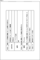
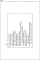
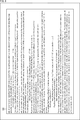
- auxiliary patch information includes parameters related to the position and size of each patch in the frame and parameters related to generation (projection method, etc.) of each patch, as shown in FIG. 6, for example. include. Examples of the semantics of these parameters are also shown in FIGS. 7 and 8.
- each parameter as shown in FIG. 6 is set to the plurality of frames based on the external setting or the information of the plurality of frames. Set to correspond. Further, for example, when the auxiliary patch information applied to the past frame is reused as in "Method 2", each parameter as shown in FIG. 6 is reused in the processing target frame.
- the parameters included in the auxiliary patch information are arbitrary and are not limited to the above example.
- the camera parameters may be included in the auxiliary patch information as described in Non-Patent Document 7.
- Non-Patent Document 7 describes, as camera parameters, a mapping (correspondence relationship) between each image of an captured image (captured image), an image projected on a two-dimensional plane (projected image), and an image at a viewpoint (viewpoint image).
- the auxiliary patch information includes a parameter (matrix) representing (for example, affine transformation). That is, in this case, information such as the position and orientation of the camera can be included in the auxiliary patch information.
- auxiliary patch information is information about a patch in which a point cloud representing a three-dimensional object as a set of points is projected onto a two-dimensional plane for each subregion, and the generated auxiliary patch information is generated.
- Auxiliary patch information may be retained, and the point clouds of the plurality of frames may be reconstructed using the same auxiliary patch information held by each other.
- the point cloud of each frame of the "section” is reconstructed by using the auxiliary patch information corresponding to all of the plurality of frames constituting the predetermined section of the point cloud in the time direction. May be good.
- this "interval” is arbitrary, and may be, for example, the entire sequence or GOF.
- the point cloud of the processing target frame may be reconstructed by using the auxiliary patch information corresponding to the past frame which is the held frame that has been processed in the past.
- auxiliary patch information auxiliary patch information applied in the past
- a flag can be used as in "Method 3", for example.
- the flag acquired from the encoding side indicates that the point cloud of each frame of the "section" is reconstructed by using the common auxiliary patch information, the section held in the auxiliary patch information holding unit.
- the point cloud of each frame in the section may be reconstructed by using the auxiliary patch information corresponding to all the frames of.
- the processing is performed using the retained auxiliary patch information corresponding to the past frame.
- the point cloud of the target frame may be reconstructed.
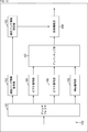
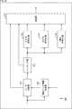
- FIG. 9 is a block diagram showing an example of the configuration of the coding device.
- the coding device 100 shown in FIG. 9 is a device (a coding device to which a video-based approach is applied) that projects 3D data such as a point cloud onto a two-dimensional plane and encodes it by a coding method for a two-dimensional image. ).
- the coding apparatus 100 performs such a process by applying the “method 1” shown in the table of FIG.
- FIG. 9 shows the main things such as the processing unit and the data flow, and not all of them are shown in FIG. That is, in the coding apparatus 100, there may be a processing unit that is not shown as a block in FIG. 9, or there may be a processing or data flow that is not shown as an arrow or the like in FIG.
- the coding apparatus 100 includes a patch decomposition unit 111, a packing unit 112, an auxiliary patch information compression unit 113, a video coding unit 114, a video coding unit 115, an OMap coding unit 116, and a multiplexer 117.
- a patch decomposition unit 111 the coding apparatus 100 includes a packing unit 112, an auxiliary patch information compression unit 113, a video coding unit 114, a video coding unit 115, an OMap coding unit 116, and a multiplexer 117.
- the patch decomposition unit 111 performs processing related to 3D data decomposition. For example, the patch decomposition unit 111 acquires 3D data (for example, a point cloud) representing a three-dimensional structure input to the coding apparatus 100. Further, the patch decomposition unit 111 decomposes the acquired 3D data into a plurality of small areas (connection components), projects the 3D data on each small area on a two-dimensional plane, and patches the geometry data and the attribute data. To generate. That is, the patch decomposition unit 111 decomposes the 3D data into patches. In other words, the patch decomposition unit 111 can be said to be a patch generation unit that generates a patch from 3D data.
- 3D data for example, a point cloud
- the patch disassembling unit 111 supplies each generated patch to the packing unit 112. Further, the patch disassembling unit 111 supplies the auxiliary patch information used for generating the patch to the packing unit 112 and the auxiliary patch information compression unit 113.
- the packing unit 112 performs processing related to data packing. For example, the packing unit 112 acquires information about the patch supplied from the patch disassembling unit 111. Further, the packing unit 112 arranges each acquired patch on a two-dimensional image and packs it as a video frame. For example, the packing unit 112 packs a patch of geometry data as a video frame and generates a geometry video frame (Geometry video frame (s)). Further, the packing unit 112 packs the patch of the attribute data as a video frame and generates a color video frame (s). Further, the packing unit 112 generates an Occupancy Map indicating the presence or absence of the patch.
- the packing unit 112 supplies them to the processing unit in the subsequent stage.
- the packing unit 112 supplies the geometry video frame to the video coding unit 114, the color video frame to the video coding unit 115, and the occupancy map to the OMap coding unit 116.
- Auxiliary patch information compression unit 113 performs processing related to compression of auxiliary patch information.
- the auxiliary patch information compression unit 113 acquires the auxiliary patch information supplied from the patch decomposition unit 111.
- the auxiliary patch information compression unit 113 encodes (compresses) the acquired auxiliary patch information by a coding method other than the coding method for the two-dimensional image. This coding method is arbitrary as long as it is not for a two-dimensional image.
- the auxiliary patch information compression unit 113 supplies the obtained coded data of the auxiliary patch information to the multiplexer 117.
- the video coding unit 114 performs processing related to coding of the geometry video frame. For example, the video coding unit 114 acquires the geometry video frame supplied from the packing unit 112. Further, the video coding unit 114 encodes the acquired geometry video frame by a coding method for an arbitrary two-dimensional image such as AVC or HEVC. The video coding unit 114 supplies the coded data of the geometry video frame obtained by the coding to the multiplexer 117.
- the video coding unit 115 performs processing related to coding of a color video frame. For example, the video coding unit 115 acquires a color video frame supplied from the packing unit 112. Further, the video coding unit 115 encodes the acquired color video frame by a coding method for an arbitrary two-dimensional image such as AVC or HEVC. The video coding unit 115 supplies the coded data of the color video frame obtained by the coding to the multiplexer 117.
- the OMap coding unit 116 performs processing related to coding the video frame of the occupancy map. For example, the OMap coding unit 116 acquires the occupancy map supplied from the packing unit 112. Further, the OMap coding unit 116 encodes the acquired occupancy map by, for example, a coding method for an arbitrary two-dimensional image. The OMap coding unit 116 supplies the encoded data of the occupancy map obtained by the coding to the multiplexer 117.
- the multiplexer 117 performs processing related to multiplexing. For example, the multiplexer 117 acquires the encoded data of the auxiliary patch information supplied from the auxiliary patch information compression unit 113. Further, for example, the multiplexer 117 acquires the coded data of the geometry video frame supplied from the video coding unit 114. Further, for example, the multiplexer 117 acquires the coded data of the color video frame supplied from the video coding unit 115. Further, for example, the multiplexer 117 acquires the encoded data of the occupancy map supplied from the OMap coding unit 116.
- the multiplexer 117 multiplexes the acquired information to generate a bit stream.
- the multiplexer 117 outputs the generated bit stream to the outside of the coding apparatus 100.
- the coding device 100 further has an auxiliary patch information generation unit 101.
- Auxiliary patch information generation unit 101 performs processing related to generation of auxiliary patch information.
- the auxiliary patch information generation unit 101 can generate auxiliary patch information so as to correspond to all of a plurality of frames constituting the “section” to be processed. That is, the auxiliary patch information generation unit 101 can generate auxiliary patch information corresponding to all the frames constituting the "section" to be processed.
- This "section” is ⁇ 1.
- Auxiliary patch information> For example, it may be the entire sequence, GOF, or other data units.
- the auxiliary patch information generation unit 101 acquires 3D data (for example, point cloud data) input to the encoding device 100, and based on the information of each frame in the "section" of the processing target of the 3D data. , Auxiliary patch information corresponding to all frames constituting the "section" to be processed can be generated.
- 3D data for example, point cloud data
- the auxiliary patch information generation unit 101 acquires setting information (also referred to as an external setting) supplied from the outside of the coding apparatus 100, and based on the external setting, all frames constituting the "section" to be processed Corresponding auxiliary patch information can be generated.
- setting information also referred to as an external setting
- the auxiliary patch information generation unit 101 supplies the generated auxiliary patch information to the patch disassembly unit 111.
- the patch decomposition unit 111 uses the supplied auxiliary patch information to generate a patch for each frame of the “section” to be processed.
- the auxiliary patch information generation unit 101 supplies the generated patch and the auxiliary patch information applied to the generation of the patch to the packing unit 112. Further, the auxiliary patch information generation unit 101 supplies the auxiliary patch information applied to the patch generation to the auxiliary patch information compression unit 113.
- the auxiliary patch information compression unit 113 has auxiliary patch information supplied from the patch decomposition unit 111, that is, auxiliary patch information generated by the auxiliary patch information generation unit 101 and corresponding to all frames constituting the “section” to be processed. Is encoded (compressed) and the encoded data is generated. The auxiliary patch information compression unit 113 supplies the generated coded data to the multiplexer 117.
- the encoding device 100 can share auxiliary patch information in a plurality of frames and generate a patch using the same auxiliary patch information. Further, the coding device 100 can supply auxiliary patch information corresponding to the plurality of frames to the decoding side. Therefore, the decoding side can reconstruct the 3D data by using the auxiliary patch information corresponding to the plurality of frames. Therefore, it is possible to suppress an increase in the decoding load.
- each processing unit may be configured by a logic circuit that realizes the above-mentioned processing.
- each processing unit has, for example, a CPU (Central Processing Unit), a ROM (Read Only Memory), a RAM (Random Access Memory), and the like, and the above-mentioned processing is realized by executing a program using them. You may do so.
- each processing unit may have both configurations, and a part of the above-mentioned processing may be realized by a logic circuit, and the other may be realized by executing a program.
- the configurations of the respective processing units may be independent of each other. For example, some processing units realize a part of the above-mentioned processing by a logic circuit, and some other processing units execute a program.
- the above-mentioned processing may be realized by the other processing unit by both the logic circuit and the execution of the program.
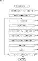
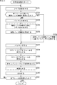
- the auxiliary patch information generation unit 101 of the coding device 100 When the coding process is started, the auxiliary patch information generation unit 101 of the coding device 100 performs, for example, RD optimization based on the acquired frame in step S101, and performs the optimum auxiliary in the “section” to be processed. Generate patch information.
- step S102 the auxiliary patch information generation unit 101 determines whether or not all the frames of the "section" to be processed have been processed. If it is determined that an unprocessed frame exists, the process returns to step S101, and the subsequent processes are repeated.
- the coding device 100 executes each process of step S101 and step S102 for all frames of the processing target section.
- step S101 the optimum auxiliary patch information for all the frames of the processing target section, that is, the auxiliary patch information corresponding to all the frames of the processing target section is obtained. Will be generated.
- step S102 determines whether all the frames of the "section" to be processed have been processed. If it is determined in step S102 that all the frames of the "section" to be processed have been processed, the processing proceeds to step S103.
- step S103 the auxiliary patch information compression unit 113 compresses the auxiliary patch information obtained by the process of step S101.
- the process proceeds to step S104.
- step S104 the patch decomposition unit 111 decomposes 3D data (for example, a point cloud) into small areas (connection components) for the frame to be processed based on the auxiliary patch information generated in step S101, and divides each small area into small areas (connection components). Data is projected onto a two-dimensional plane (projection plane) to generate geometry data patches and attribute data patches.
- 3D data for example, a point cloud
- connection components small areas
- step S105 the packing unit 112 packs each patch generated in step S104 to generate a geometry video frame and a color video frame. In addition, the packing unit 112 generates an occupancy map.
- step S106 the video coding unit 114 encodes the geometry video frame obtained by the process of step S105 by the coding method for the two-dimensional image.
- step S107 the video coding unit 115 encodes the color video frame obtained by the process of step S105 by the coding method for the two-dimensional image.
- step S108 the OMap coding unit 116 encodes the occupancy map obtained by the process of step S105.
- step S109 the multiplexer 117 multiplexes the various information generated as described above and generates a bit stream including the information.
- step S110 the multiplexer 117 outputs the bit stream generated by the process of step S109 to the outside of the coding device 100.
- step S111 the patch disassembling unit 111 determines whether or not all the frames in the processing target section have been processed. If there are unprocessed frames, the process returns to step S104. That is, each process of step S104 to step S111 is executed for each frame of the processing target section, and the bit stream of each frame is output. If it is determined in step S111 that all frames have been processed for the processing target section, the coding process ends.
- the encoding device 100 can share auxiliary patch information in a plurality of frames and generate a patch using the same auxiliary patch information. Therefore, the decoding side can reconstruct the 3D data by using the auxiliary patch information corresponding to the plurality of frames. Therefore, it is possible to suppress an increase in the decoding load.
- Auxiliary patch information can also be generated based on external settings.
- the user or the like of the coding apparatus 100 may specify various parameters of the auxiliary patch information as shown in FIG. 6, and the auxiliary patch information generation unit 101 may generate the auxiliary patch information using those parameters. ..
- step S132 the auxiliary patch information compression unit 113 encodes (compresses) the auxiliary patch information generated in step S131.
- step S140 Each process of steps S133 to S140 is executed in the same manner as each process of steps S104 to S111 of FIG. If it is determined in step S140 that all frames have been processed for the processing target section, the coding process ends.
- the encoding device 100 can share auxiliary patch information in a plurality of frames and generate a patch using the same auxiliary patch information. Therefore, the decoding side can reconstruct the 3D data by using the auxiliary patch information corresponding to the plurality of frames. Therefore, it is possible to suppress an increase in the decoding load.
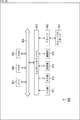
- FIG. 12 is a block diagram showing an example of the configuration of a decoding device, which is an aspect of an image processing device to which the present technology is applied.
- the decoding device 150 shown in FIG. 12 decodes the coded data obtained by projecting 3D data such as a point cloud onto a two-dimensional plane and encoding it by a decoding method for a two-dimensional image, and reconstructs the 3D data. (Decoding device to which a video-based approach is applied).
- the decoding device 150 is a decoding device corresponding to the coding device 100 of FIG. 9, and can decode the bit stream generated by the coding device 100 to reconstruct the 3D data. That is, the decoding device 150 performs such a process by applying the "method 1" shown in the table of FIG.
- FIG. 12 shows the main things such as the processing unit and the data flow, and not all of them are shown in FIG. That is, in the decoding device 150, there may be a processing unit that is not shown as a block in FIG. 12, or there may be a processing or data flow that is not shown as an arrow or the like in FIG.
- the decoding device 150 includes a demultiplexer 161, an auxiliary patch information decoding unit 162, an auxiliary patch information holding unit 163, a video decoding unit 164, a video decoding unit 165, an OMap decoding unit 166, and an unpacking unit 167. And has a 3D reconstruction unit 168.
- the demultiplexer 161 performs processing related to data demultiplexing. For example, the demultiplexer 161 can acquire a bit stream input to the decoding device 150. This bit stream is supplied from, for example, the encoding device 100.
- the demultiplexer 161 can demultiplex this bit stream.
- the demultiplexer 161 can extract the coded data of the auxiliary patch information from the bit stream by demultiplexing.
- the demultiplexer 161 can also extract the coded data of the geometry video frame from the bitstream by demultiplexing.
- the demultiplexer 161 can extract the coded data of the color video frame from the bit stream by demultiplexing.
- the demultiplexer 161 can extract the encoded data of the occupancy map from the bit stream by demultiplexing.
- the demultiplexer 161 can supply the extracted data to the subsequent processing unit.
- the demultiplexer 161 can supply the coded data of the extracted auxiliary patch information to the auxiliary patch information decoding unit 162.
- the demultiplexer 161 can supply the coded data of the extracted geometry video frame to the video decoding unit 164.
- the demultiplexer 161 can supply the coded data of the extracted color video frame to the video decoding unit 165.
- the demultiplexer 161 can supply the coded data of the extracted occupancy map to the OMap decoding unit 166.
- the auxiliary patch information decoding unit 162 performs processing related to decoding the coded data of the auxiliary patch information. For example, the auxiliary patch information decoding unit 162 can acquire the encoded data of the auxiliary patch information supplied from the demultiplexer 161. Further, the auxiliary patch information decoding unit 162 can decode the coded data and generate the auxiliary patch information. This decoding method is arbitrary as long as it corresponds to the coding method applied at the time of coding (for example, the coding method applied by the auxiliary patch information compression unit 113) (decoding method not for a two-dimensional image). be. Further, the auxiliary patch information decoding unit 162 supplies the auxiliary patch information to the auxiliary patch information holding unit 163.
- the auxiliary patch information holding unit 163 has a storage medium such as a semiconductor memory and performs processing related to holding the auxiliary patch information. For example, the auxiliary patch information holding unit 163 can acquire the auxiliary patch information supplied from the auxiliary patch information decoding unit 162. Further, the auxiliary patch information holding unit 163 can hold the acquired auxiliary patch information in its own storage medium. Further, the auxiliary patch information holding unit 163 may supply the holding auxiliary patch information to the 3D reconstruction unit 168 as needed (for example, at a predetermined timing or based on a predetermined request).
- the video decoding unit 164 performs processing related to decoding the coded data of the geometry video frame. For example, the video decoding unit 164 can acquire the coded data of the geometry video frame supplied from the demultiplexer 161. Further, the video decoding unit 164 can decode the coded data and generate a geometry video frame. Further, the video decoding unit 164 can supply the geometry video frame to the unpacking unit 167.
- the video decoding unit 165 performs processing related to decoding the coded data of the color video frame. For example, the video decoding unit 165 can acquire the coded data of the color video frame supplied from the demultiplexer 161. Further, the video decoding unit 165 can decode the coded data and generate a color video frame. Further, the video decoding unit 165 can supply the color video frame to the unpacking unit 167.
- the OMap decoding unit 166 performs processing related to decoding the coded data of the occupancy map. For example, the OMap decoding unit 166 can acquire the coded data of the occupancy map supplied from the demultiplexer 161. In addition, the OMap decoding unit 166 can decode the coded data and generate an occupancy map. Further, the OMap decoding unit 166 can supply the occupancy map to the unpacking unit 167.
- the unpacking unit 167 performs processing related to unpacking. For example, the unpacking unit 167 can acquire the geometry video frame supplied from the video decoding unit 164. Further, the unpacking unit 167 can acquire the color video frame supplied from the video decoding unit 165. In addition, the unpacking unit 167 can acquire the occupancy map supplied from the OMap decoding unit 166.
- the unpacking unit 167 can unpack the geometry video frame and the color video frame based on the acquired occupancy map and the like, and extract the patch of the geometry data and the attribute data.
- the unpacking unit 167 can supply the geometry data, the patch of the attribute data, and the like to the 3D reconstruction unit 168.
- the 3D reconstruction unit 168 performs processing related to reconstruction of 3D data.
- the 3D reconstruction unit 168 can acquire the auxiliary patch information held in the auxiliary patch information holding unit 163.
- the 3D reconstruction unit 168 can acquire a patch of geometry data supplied from the unpacking unit 167.
- the 3D reconstruction unit 168 can acquire a patch or the like of attribute data supplied from the unpacking unit 167.
- the 3D reconstruction unit 168 can acquire the occupancy map supplied from the unpacking unit 167.
- the 3D reconstruction unit 168 reconstructs 3D data (for example, Point Cloud) using the information.
- the 3D reconstruction unit 168 reconstructs the 3D data of a plurality of frames using the same auxiliary patch information held in the auxiliary patch information holding unit 163.
- the auxiliary patch information holding unit 163 holds auxiliary patch information corresponding to all frames constituting the “section” of the processing target generated by the auxiliary patch information generation unit 101 of the encoding device 100, and the processing target thereof.
- the auxiliary patch information is supplied to the 3D reconstruction unit 168.
- the 3D reconstruction unit 168 reconstructs 3D data using this common auxiliary patch information in each frame of the processing target section.
- this "interval" is arbitrary and may be the entire sequence, GOF, or other data unit.
- the 3D reconstruction unit 168 outputs the 3D data obtained by such processing to the outside of the decoding device 150.
- This 3D data is, for example, supplied to a display unit to display the image, recorded on a recording medium, or supplied to another device via communication.
- each processing unit may be configured by a logic circuit that realizes the above-mentioned processing.
- each processing unit may have, for example, a CPU, ROM, RAM, etc., and execute a program using them to realize the above-mentioned processing.
- each processing unit may have both configurations, and a part of the above-mentioned processing may be realized by a logic circuit, and the other may be realized by executing a program.
- the configurations of the respective processing units may be independent of each other. For example, some processing units realize a part of the above-mentioned processing by a logic circuit, and some other processing units execute a program.
- the above-mentioned processing may be realized by the other processing unit by both the logic circuit and the execution of the program.
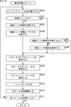
- the demultiplexer 161 of the decoding device 150 demultiplexes the bit stream in step S161.
- step S162 the demultiplexer 161 determines whether or not the processing target frame is the first frame of the processing target section. If it is determined to be the first frame, the process proceeds to step S163.
- step S163 the auxiliary patch information decoding unit 162 decodes the encoded data of the auxiliary patch information extracted from the bit stream by the process of step S161.
- step S164 the auxiliary patch information holding unit 163 holds the obtained auxiliary patch information decoded in step S163.
- step S165 the processing of steps S163 and S164 is omitted, and the processing proceeds to step S165.
- step S165 the video decoding unit 164 decodes the coded data of the geometry video frame extracted from the bit stream by the process of step S161.
- step S166 the video decoding unit 165 decodes the coded data of the color video frame extracted from the bit stream by the process of step S161.
- step S167 the OMap decoding unit 166 decodes the encoded data of the occupancy map extracted from the bit stream by the process of step S161.
- step S168 the unpacking unit 167 unpacks the geometry video frame and the color video frame, respectively, based on the occupancy map or the like.
- step S169 the 3D reconstruction unit 168 reconstructs 3D data such as a point cloud based on the auxiliary patch information held in step S164 and various information obtained in step S168.
- the auxiliary patch information is decoded and retained only in the first frame of the processing target section. Therefore, the 3D reconstruction unit 168 reconstructs the 3D data of a plurality of frames by using the same auxiliary patch information held by each other.
- step S170 the demultiplexer 161 determines whether or not all the frames in the processing target section have been processed. If there are unprocessed frames, the process returns to step S161. That is, each process of step S161 to step S170 is executed for each frame of the processing target section, and the 3D data of each frame is reconstructed. If it is determined in step S170 that all frames have been processed for the processing target section, the decoding process ends.
- the decoding device 150 can share auxiliary patch information in a plurality of frames and reconstruct 3D data using the same auxiliary patch information.
- the decoding device 150 uses auxiliary patch information corresponding to a plurality of frames (for example, auxiliary patch information corresponding to all frames of the processing target section) of the plurality of frames (for example, each frame of the processing target section).
- the 3D data can be reconstructed. Therefore, the number of times the auxiliary patch information is decoded can be reduced, and an increase in the decoding load can be suppressed.
- the 3D reconstruction unit 168 may read the auxiliary patch information held in the auxiliary patch information holding unit 163 and use it for reconstructing the 3D data, synchronization of the geometry data or attribute data with the auxiliary patch information. Can be taken more easily.
- the decoding device 150 uses the flowchart of FIG. Decryption processing is performed as in. That is, the coding process may be executed as shown in the flowchart of FIG. 10, or may be executed as shown in the flowchart of FIG.
- FIG. 14 is a block diagram showing an example of the configuration of the coding device.
- the coding device 200 shown in FIG. 14 is a device (a coding device to which a video-based approach is applied) that projects 3D data such as a point cloud onto a two-dimensional plane and encodes it by a coding method for a two-dimensional image. ).
- the coding apparatus 200 performs such a process by applying the “method 2” shown in the table of FIG.
- FIG. 14 shows the main things such as the processing unit and the data flow, and not all of them are shown in FIG. That is, in the coding apparatus 200, there may be a processing unit that is not shown as a block in FIG. 14, or there may be a processing or data flow that is not shown as an arrow or the like in FIG.
- the coding device 200 has the patch decomposition unit 111 to the multiplexer 117 like the coding device 100 (FIG. 9). However, the coding device 200 has an auxiliary patch information holding unit 201 instead of the auxiliary patch information generating unit 101 of the coding device 100.
- the auxiliary patch information holding unit 201 has a storage medium such as a semiconductor memory, and performs processing related to holding the auxiliary patch information. For example, the auxiliary patch information holding unit 201 can acquire the auxiliary patch information used for patch generation in the patch disassembling unit 111 and hold it in its own storage medium. Further, the auxiliary patch information holding unit 201 may supply the holding auxiliary patch information to the patch disassembling unit 111 as needed (for example, at a predetermined timing or based on a predetermined request).
- the number of auxiliary patch information held by the auxiliary patch information holding unit 201 is arbitrary. For example, only a single auxiliary patch information, that is, the last retained auxiliary patch information (latest auxiliary patch information) may be retained, or a plurality of auxiliary patch information may be retained. You may do so.
- the patch decomposition unit 111 decomposes the 3D data input to the encoding device 200 into a plurality of small areas (connection components), projects the 3D data on each small area on a two-dimensional plane, and patches and attributes of the geometry data. Generate a patch of data. At that time, the patch decomposition unit 111 can generate auxiliary patch information corresponding to the processing target frame, and can generate a patch using the auxiliary patch information corresponding to the processing target frame. Further, the patch disassembling unit 111 acquires the auxiliary patch information held in the auxiliary patch information holding unit 201, that is, the auxiliary patch information corresponding to the past frame, and patches using the auxiliary patch information corresponding to the past frame. Can be generated.
- the patch decomposition unit 111 generates auxiliary patch information for the first frame of the processing target section, generates a patch using the auxiliary patch information, and for frames other than the first frame, the previous frame.
- the auxiliary patch information used for patch generation is acquired from the auxiliary patch information holding unit 201, and the patch is generated using the auxiliary patch information.
- the patch decomposition unit 111 may generate auxiliary patch information corresponding to the processing target frame in a frame other than the first frame of the processing target section. Further, the patch disassembling unit 111 may acquire the auxiliary patch information used for generating the patch in the two or more previous frames from the auxiliary patch information holding unit 201.
- the "interval" is arbitrary, and may be, for example, the entire sequence, GOF, or other data unit.
- the patch disassembling unit 111 can supply and retain the auxiliary patch information used for patch generation to the auxiliary patch information holding unit 201 as described above. By this process, the auxiliary patch information held in the auxiliary patch information holding unit 201 is updated (overwritten or added).
- the patch disassembling unit 111 When the patch disassembling unit 111 generates a patch using the auxiliary patch information acquired from the auxiliary patch information holding unit 201, the update of the auxiliary patch information holding unit 201 may be omitted. That is, the patch disassembling unit 111 may supply the auxiliary patch information to the auxiliary patch information holding unit 201 only when the auxiliary patch information is generated.
- the patch disassembling unit 111 When the patch disassembling unit 111 generates the auxiliary patch information, the patch disassembling unit 111 supplies the auxiliary patch information to the auxiliary patch information compression unit 113 and encodes (compresses) the auxiliary patch information to generate the encoded data. Further, the patch disassembling unit 111 supplies the generated geometry data and attribute data patches to the packing unit 112 together with the used auxiliary patch information.
- the packing unit 112 to the multiplexer 117 perform the same processing as in the case of the coding device 100.
- the video coding unit 114 encodes a geometry video frame and generates the coded data. Further, for example, the video coding unit 114 encodes a color video frame and generates the coded data.
- the encoding device 200 can generate a patch by reusing the auxiliary patch information corresponding to the past frame in the processing target frame. That is, the coding apparatus 200 can share auxiliary patch information in a plurality of frames and generate a patch using the same auxiliary patch information. Therefore, even on the decoding side, the auxiliary patch information corresponding to the past frame can be reused in the processing target frame to reconstruct the 3D data. Therefore, it is possible to suppress an increase in the decoding load.
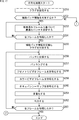
- the patch decomposition unit 111 determines in step S201 whether or not the process target frame is the first frame of the process target section. If it is determined that the frame to be processed is the first frame, the process proceeds to step S202.
- the patch decomposition unit 111 In the case of the first frame, the patch decomposition unit 111 generates auxiliary patch information corresponding to the frame to be processed in step S202, and decomposes the 3D data input using the auxiliary patch information into patches. That is, generate a patch.
- the method of generating the auxiliary patch information in this case is arbitrary.
- the auxiliary patch information may be generated based on the external setting, or the auxiliary patch information may be generated based on the 3D data.
- step S203 the auxiliary patch information compression unit 113 encodes (compresses) the generated auxiliary patch information and generates the encoded data.
- step S204 the auxiliary patch information holding unit 201 holds the generated auxiliary patch information.
- step S206 If it is determined in step S201 that the processing target frame is not the first frame of the processing target section, the process proceeds to step S205.
- step S205 the patch disassembling unit 111 acquires the auxiliary patch information (that is, the auxiliary patch information corresponding to the past frame) held in the auxiliary patch information holding unit 201, and uses the auxiliary patch information to process the target frame. Generate a patch for.
- the process of step S205 proceeds to step S206.
- step S212 the patch disassembling unit 111 determines whether or not all the frames in the processing target section have been processed. If there are unprocessed frames, the process returns to step S201. That is, each process of step S201 to step S212 is executed for each frame of the processing target section, and the bit stream of each frame is output. If it is determined in step S212 that all frames have been processed for the processing target section, the coding process ends.
- the encoding device 200 can generate a patch by reusing the auxiliary patch information corresponding to the past frame in the processing target frame. That is, the coding apparatus 200 can share auxiliary patch information in a plurality of frames and generate a patch using the same auxiliary patch information. Therefore, even on the decoding side, the auxiliary patch information corresponding to the past frame can be reused in the processing target frame to reconstruct the 3D data. Therefore, it is possible to suppress an increase in the decoding load.
- the decoding device 150 shown in FIG. 12 also corresponds to such a coding device 200. That is, the decoding device 150 decodes the coded data for the first frame to generate auxiliary patch information corresponding to the frame to be processed, and causes the auxiliary patch information holding unit 163 to hold the auxiliary patch information. Further, for frames other than the first frame, the decoding device 150 omits decoding the encoded data of the auxiliary patch information.
- the 3D reconstruction unit 168 reconstructs 3D data using the auxiliary patch information corresponding to the past frame held in the auxiliary patch information holding unit 163.
- the 3D reconstruction unit 168 reconstructs the 3D data using the auxiliary patch information corresponding to the processing target frame for the first frame, and corresponds to the past frame for the other frames. 3D data can be reconstructed using the auxiliary patch information. Therefore, an increase in load can be suppressed.
- FIG. 16 is a block diagram showing an example of the configuration of the coding device.
- the coding device 250 shown in FIG. 16 is a device (a coding device to which a video-based approach is applied) that projects 3D data such as a point cloud onto a two-dimensional plane and encodes it by a coding method for a two-dimensional image. ).
- the coding apparatus 250 performs such a process by applying the “method 3-1” shown in the table of FIG.
- FIG. 16 shows the main things such as the processing unit and the data flow, and not all of them are shown in FIG. That is, in the coding apparatus 250, there may be a processing unit that is not shown as a block in FIG. 16, or there may be a processing or data flow that is not shown as an arrow or the like in FIG.
- the coding device 250 has a flag setting unit 251 in addition to the configuration of the coding device 100 (FIG. 9).
- the flag setting unit 251 sets a flag (also referred to as an intra-section shared flag) indicating whether to generate a patch for each frame of the processing target section using common auxiliary patch information.
- This setting method is arbitrary. For example, it may be set based on an instruction from the outside of the coding device 250 such as a user. Moreover, it may be predetermined. Further, it may be set based on the 3D data input to the coding device 250.
- the auxiliary patch information generation unit 101 generates auxiliary patch information (common auxiliary patch information) corresponding to all frames in the processing target section based on the flag information set by the flag setting unit 251.
- the auxiliary patch information generation unit 101 determines the patch.
- Common auxiliary patch information is generated so as to correspond to all frames constituting the processing target section, and the patch decomposition unit 111 uses the generated common auxiliary patch information to patch each frame in the processing target section. May be generated.
- the auxiliary patch information generation unit 101 may generate the patch.
- Auxiliary patch information is generated for each frame constituting the processing target section, and the patch decomposition unit 111 generates auxiliary patch information corresponding to the frame generated by the auxiliary patch information generation unit 101 for each frame in the section. May be used to generate a patch.
- the flag setting unit 251 of the coding device 250 sets a flag (shared flag within the section) in step S251.
- step S252 the auxiliary patch information generation unit 101 determines whether or not to supply the auxiliary patch information based on the intra-section sharing flag set in step S251. If the intra-section sharing flag is true (for example, 1) and it is determined that the auxiliary patch information is shared in a plurality of frames, the process proceeds to step S253.
- each process of steps S253 to S263 is executed in the same manner as each process of steps S101 to S111. If it is determined in step S263 that all frames of the processing target section have been processed, the coding process ends.
- step S252 If it is determined in step S252 that the auxiliary patch information is not shared in a plurality of frames, the process proceeds to step S271 in FIG. In this case, auxiliary patch information is generated for each frame.
- step S271 of FIG. 18 the patch disassembling unit 111 generates auxiliary patch information, generates a patch based on the auxiliary patch information, and decomposes the 3D data into patches.
- step S272 the auxiliary patch information compression unit 113 determines whether or not the processing target frame is the first frame of the processing target section. If it is determined that it is the first frame, the process proceeds to step S273.
- step S273 the auxiliary patch information compression unit 113 encodes (compresses) the auxiliary patch information, and further adds an intra-section sharing flag to the encoded data.
- step S275 the process proceeds to step S275.
- step S272 If it is determined in step S272 that it is not the first frame, the process proceeds to step S274.
- step S274 the auxiliary patch information compression unit 113 encodes (compresses) the auxiliary patch information.
- step S275 the process proceeds to step S275.
- step S281 the patch disassembling unit 111 determines whether or not all the frames in the processing target section have been processed. If there are unprocessed frames, the process returns to step S271. That is, each process of step S271 to step S281 is executed for each frame of the processing target section, and the bit stream of each frame is output. When it is determined in step S281 that all frames have been processed for the processing target section, the coding process ends.
- the coding device 250 can select the method of generating the auxiliary patch information. Therefore, it is possible to correspond to a wider variety of specifications.
- FIG. 19 is a flowchart illustrating an example of a flow of decoding processing executed by the decoding device 150 in this case.
- each process of steps S301 to S303 is executed in the same manner as each process of steps S161 to S163 (FIG. 13).
- step S304 the auxiliary patch information holding unit 163 holds the above-mentioned intra-section sharing flag in addition to the auxiliary patch information.
- the auxiliary patch information decoding unit 162 determines in step S305 whether or not to share the auxiliary patch information in a plurality of frames. If it is determined that the auxiliary patch information is not shared, the auxiliary patch information decoding unit 162 decodes the encoded data and generates the auxiliary patch information in step S306. When the auxiliary patch information is generated, the process proceeds to step S307. If it is determined in step S305 that the auxiliary patch information is shared, the process proceeds to step S307.
- step S312 the demultiplexer 161 determines whether or not all the frames in the processing target section have been processed. If there are unprocessed frames, the process returns to step S301. That is, each process of step S301 to step S312 is executed for each frame of the processing target section, and 3D data of each frame is output. If it is determined in step S312 that all frames have been processed for the processing target section, the decoding process ends.
- FIG. 20 is a block diagram showing an example of the configuration of the coding device.
- the coding device 300 shown in FIG. 20 is a device (a coding device to which a video-based approach is applied) that projects 3D data such as a point cloud onto a two-dimensional plane and encodes it by a coding method for a two-dimensional image. ).
- the coding apparatus 300 performs such a process by applying the “method 3-2” shown in the table of FIG.
- FIG. 20 shows the main things such as the processing unit and the data flow, and not all of them are shown in FIG. 20. That is, in the coding apparatus 300, there may be a processing unit that is not shown as a block in FIG. 20, or there may be a processing or data flow that is not shown as an arrow or the like in FIG.
- the coding device 300 has a flag setting unit 301 in addition to the configuration of the coding device 200 (FIG. 14).
- the flag setting unit 301 sets a flag (also referred to as a reuse flag) indicating whether to generate a patch for the processing target frame using the auxiliary patch information corresponding to the past frame.
- This setting method is arbitrary. For example, it may be set based on an instruction from the outside of the coding device 300 by a user or the like. Moreover, it may be predetermined. Further, it may be set based on the 3D data input to the coding device 300.
- the patch decomposition unit 111 uses the auxiliary patch information corresponding to the past frame held in the auxiliary patch information holding unit 201 based on the flag information set by the flag setting unit 301 to patch the frame to be processed. To generate.
- the patch decomposition unit 111 sets the auxiliary patch information holding unit.
- the patch of the processing target frame may be generated by using the auxiliary patch information corresponding to the past frame held in 201.
- the patch decomposition unit 111 performs the processing target frame.
- Auxiliary patch information corresponding to the above may be generated, and the generated auxiliary patch information may be used to generate a patch for the frame to be processed.
- the flag setting unit 301 of the coding device 250 sets the flag (reuse flag) in step S331.
- step S332 the patch disassembly unit 111 determines whether or not to apply the auxiliary patch information used for the previous frame to the processing target frame based on the reuse flag set in step S331. If the reuse flag is false (for example, 0) and it is determined that the auxiliary patch information used in the previous frame is not reused, the process proceeds to step S333.
- step S333 the patch decomposition unit 111 generates auxiliary patch information corresponding to the frame to be processed, generates a patch based on the auxiliary patch information, and decomposes the 3D data into patches.
- step S334 the auxiliary patch information compression unit 113 encodes (compresses) the auxiliary patch information, and further adds a reuse flag to the encoded data.
- step S335 the auxiliary patch information holding unit 201 holds the auxiliary patch information generated in step S333.
- step S335 the process proceeds to step S337.
- step S332 If it is determined in step S332 that the auxiliary patch information used for the previous frame is to be reused, the process proceeds to step S336.
- step S336 the patch disassembling unit 111 reads the auxiliary patch information held in the auxiliary patch information holding unit 201, generates a patch based on the auxiliary patch information, and decomposes the 3D data into patches.
- step S337 the process proceeds to step S337.
- Steps S337 to S342 are basically the same as the processes of steps S206 to S211 (FIG. 15).
- the patch disassembling unit 111 determines whether or not all the frames in the processing target section have been processed. If there are unprocessed frames, the process returns to step S331. That is, each process of step S331 to step S343 is executed for each frame of the processing target section, and the bit stream of each frame is output. When it is determined in step S343 that all frames have been processed for the processing target section, the coding process ends.
- FIG. 22 is a flowchart illustrating an example of the flow of the decoding process executed by the decoding device 150 in this case.
- the demultiplexer 161 of the decoding device 150 demultiplexes the bit stream in step S371.
- step S372 the demultiplexer 161 determines whether or not to apply the auxiliary patch information used for the past frame to the processing target frame based on the reuse flag. If it is determined that the auxiliary patch information used for the past frame is not applied to the processing target frame, the process proceeds to step S373. If it is determined that the auxiliary patch information used in the past frame is applied to the processing target frame, the processing proceeds to step S375.
- steps S371 to S380 are executed for each frame, and when it is determined that all the frames have been processed in step S380, the decoding process ends.
- 3D Information) 414 is generated.
- the captured image 411 of each camera is used as a texture (attribute data) and transmitted together with the three-dimensional information 414. In other words, information similar to the point cloud video-based approach is transmitted.
- the captured image and depth map of the fixed camera 402 with a fixed angle correspond to the patches of geometry data and attribute data in the video-based approach, the configuration of each patch does not change significantly. Therefore, the above-mentioned technology can be applied to share patch information in a plurality of frames. Then, by applying this technology, it is possible to suppress an increase in the load of decoding the point cloud.
- each patch can be represented by using a camera parameter indicating the position, posture, etc. of each fixed camera 402.
- a parameter for example, a matrix
- a mapping between images such as a captured image, a projected image, and a viewpoint image
- each patch can be represented efficiently.
- the present technology can be applied to an image processing system 500 having a server 501 for transmitting and receiving 3D data and a client 502 as shown in FIG. 24.
- the server 501 and the client 502 are connected to each other so as to be able to communicate with each other via an arbitrary network 503, and for example, 3D data can be transmitted from the server 501 to the client 502.
- the server 501 may be configured as shown in FIG. 25 and the client 502 may be configured as shown in FIG.
- the server 501 has an auxiliary patch information generation unit 101, a patch decomposition unit 111, a packing unit 112, a video coding unit 114 to an OMap coding unit 116, and a transmission unit 511, and the client 502 is a reception unit 521.
- Auxiliary patch information holding unit 163 to 3D reconstructing unit 168 can be provided.
- the transmission unit 511 of the server 501 transmits the auxiliary patch information supplied from the patch decomposition unit 111 and the coded data of each video frame supplied from the video coding unit 114 to the OMap coding unit 116 to the client.
- the receiving unit 521 of the client 502 receives those data.
- Auxiliary patch information can be held by the auxiliary patch information holding unit 163.
- the geometry video frame can be decoded by the video decoding unit 164.
- the color video frame can be decoded by the video decoding unit 165.
- the occupancy map can be decoded by the OMap decoding unit 166.
- the client 502 when transmitting and receiving data, it is not necessary to multiplex by a multiplexer or demultiplex by a demultiplexer, so that the client 502 does not use a decoder for a video-based approach and has an existing two-dimensional structure.
- the data supplied from the server 501 can be decoded using the image decoder.
- the configuration for 3D data reconstruction on the right side of the dotted line in FIG. 26 is necessary, it can be treated as a later process. Therefore, it is possible to suppress an increase in the load of transmitting and receiving data between the server 501 and the client 502.
- the server 501 receives the request (step S501).
- step S502 when the server 501 transmits the auxiliary patch information to the client 502 (step S502), the client 502 receives it (step S512).
- step S503 when the server 501 transmits the coded data of the geometry video frame (step S503), the client 502 receives it (step S513) and decodes it (step S514).
- step S504 when the server 501 transmits the coded data of the color video frame (step S504), the client 502 receives it (step S515) and decodes it (step S516).
- step S505 when the server 501 transmits the encoded data of the occupancy map (step S505), the client 502 receives it (step S517) and decodes it (step S518).
- the server 501 and the client 502 can individually transmit and receive the auxiliary patch information, the geometry video frame, the color video frame, and the occupancy map and decode them, so that the existing codec for the two-dimensional image can be used. These processes can be easily performed by using.
- the client 502 When the transmission / reception of data is completed, the client 502 unpacks (step S519) and reconstructs the 3D data (step S520).
- the server 501 performs each process of steps S503 to S505 for all frames. Then, if it is determined in step S506 that all frames have been processed, the process proceeds to step S507. Then, the server 501 executes each process of steps S502 to S507 for each requested content. Then, in step S507, when it is determined that all the requested contents have been processed, the processing is terminated.
- the client 502 performs each process of step S513 to step S521 for all frames. Then, if it is determined in step S521 that all frames have been processed, the processing proceeds to step S522. Then, the client 502 executes each process of step S512 to step S522 for each requested content. Then, in step S522, when it is determined that all the requested contents have been processed, the processing is terminated.
- FIG. 28 is a block diagram showing a configuration example of computer hardware that executes the above-mentioned series of processes programmatically.
- the CPU Central Processing Unit
- ROM Read Only Memory
- RAM Random Access Memory
- the input / output interface 910 is also connected to the bus 904.
- An input unit 911, an output unit 912, a storage unit 913, a communication unit 914, and a drive 915 are connected to the input / output interface 910.
- the input unit 911 includes, for example, a keyboard, a mouse, a microphone, a touch panel, an input terminal, and the like.
- the output unit 912 includes, for example, a display, a speaker, an output terminal, and the like.
- the storage unit 913 includes, for example, a hard disk, a RAM disk, a non-volatile memory, or the like.
- the communication unit 914 includes, for example, a network interface.
- the drive 915 drives a removable medium 921 such as a magnetic disk, an optical disk, a magneto-optical disk, or a semiconductor memory.
- the CPU 901 loads the program stored in the storage unit 913 into the RAM 903 via the input / output interface 910 and the bus 904 and executes the above-described series. Is processed.
- the RAM 903 also appropriately stores data and the like necessary for the CPU 901 to execute various processes.
- the program executed by the computer can be recorded and applied to the removable media 921 as a package media or the like, for example.
- the program can be installed in the storage unit 913 via the input / output interface 910 by mounting the removable media 921 in the drive 915.
- This program can also be provided via wired or wireless transmission media such as local area networks, the Internet, and digital satellite broadcasting. In that case, the program can be received by the communication unit 914 and installed in the storage unit 913.
- this program can be installed in advance in ROM 902 or storage unit 913.
- the encoding device, the decoding device, the server, the client, etc. have been described as application examples of the present technology, but the present technology can be applied to any configuration.
- this technology is a transmitter or receiver (for example, a television receiver or mobile phone) for satellite broadcasting, wired broadcasting such as cable TV, distribution on the Internet, and distribution to terminals by cellular communication, or It can be applied to various electronic devices such as devices (for example, hard disk recorders and cameras) that record images on media such as optical disks, magnetic disks, and flash memories, and reproduce images from these storage media.
- devices for example, hard disk recorders and cameras
- a processor as a system LSI (Large Scale Integration) or the like (for example, a video processor), a module using a plurality of processors (for example, a video module), a unit using a plurality of modules (for example, a video unit)
- a processor as a system LSI (Large Scale Integration) or the like
- a module using a plurality of processors for example, a video module
- a unit using a plurality of modules for example, a video unit
- it can be implemented as a configuration of a part of the device, such as a set (for example, a video set) in which other functions are added to the unit.
- this technology can be applied to a network system composed of a plurality of devices.
- the present technology may be implemented as cloud computing that is shared and jointly processed by a plurality of devices via a network.
- this technology is implemented in a cloud service that provides services related to images (moving images) to arbitrary terminals such as computers, AV (AudioVisual) devices, portable information processing terminals, and IoT (Internet of Things) devices. You may try to do it.
- the system means a set of a plurality of components (devices, modules (parts), etc.), and it does not matter whether all the components are in the same housing. Therefore, a plurality of devices housed in separate housings and connected via a network, and a device in which a plurality of modules are housed in one housing are both systems. ..
- Systems, devices, processing departments, etc. to which this technology is applied can be used in any field such as transportation, medical care, crime prevention, agriculture, livestock industry, mining, beauty, factories, home appliances, weather, nature monitoring, etc. .. Moreover, the use is arbitrary.
- the "flag” is information for identifying a plurality of states, and is not only information used for identifying two states of true (1) or false (0), but also three or more states. It also contains information that can identify the state. Therefore, the value that this "flag” can take may be, for example, 2 values of 1/0 or 3 or more values. That is, the number of bits constituting this "flag” is arbitrary, and may be 1 bit or a plurality of bits.
- the identification information (including the flag) is assumed to include not only the identification information in the bit stream but also the difference information of the identification information with respect to a certain reference information in the bit stream. In, the "flag” and “identification information” include not only the information but also the difference information with respect to the reference information.
- various information (metadata, etc.) regarding the coded data may be transmitted or recorded in any form as long as it is associated with the coded data.
- the term "associate" means, for example, to make the other data available (linkable) when processing one data. That is, the data associated with each other may be combined as one data or may be individual data.
- the information associated with the coded data (image) may be transmitted on a transmission path different from the coded data (image).
- the information associated with the coded data (image) may be recorded on a recording medium (or another recording area of the same recording medium) different from the coded data (image). good.
- this "association" may be a part of the data, not the entire data. For example, an image and information corresponding to the image may be associated with each other in an arbitrary unit such as a plurality of frames, one frame, or a part within the frame.
- the embodiment of the present technology is not limited to the above-described embodiment, and various changes can be made without departing from the gist of the present technology.
- the configuration described as one device (or processing unit) may be divided and configured as a plurality of devices (or processing units).
- the configurations described above as a plurality of devices (or processing units) may be collectively configured as one device (or processing unit).
- a configuration other than the above may be added to the configuration of each device (or each processing unit).
- a part of the configuration of one device (or processing unit) may be included in the configuration of another device (or other processing unit). ..
- the above-mentioned program may be executed in any device.
- the device may have necessary functions (functional blocks, etc.) so that necessary information can be obtained.
- each step of one flowchart may be executed by one device, or may be shared and executed by a plurality of devices.
- the plurality of processes may be executed by one device, or may be shared and executed by a plurality of devices.
- a plurality of processes included in one step can be executed as processes of a plurality of steps.
- the processes described as a plurality of steps can be collectively executed as one step.
- the processing of the steps for writing the program may be executed in chronological order in the order described in the present specification, and the calls may be made in parallel or in parallel. It may be executed individually at the required timing such as when it is broken. That is, as long as there is no contradiction, the processing of each step may be executed in an order different from the above-mentioned order. Further, the processing of the step for writing this program may be executed in parallel with the processing of another program, or may be executed in combination with the processing of another program.
- a plurality of technologies related to this technology can be independently implemented independently as long as there is no contradiction.
- any plurality of the present technologies can be used in combination.
- some or all of the techniques described in any of the embodiments may be combined with some or all of the techniques described in other embodiments. It is also possible to carry out a part or all of any of the above-mentioned techniques in combination with other techniques not described above.
- Auxiliary patch information which is information about a patch in which a point cloud representing a three-dimensional object as a set of points is projected onto a two-dimensional plane for each subregion, constitutes a predetermined section of the point cloud in the time direction.
- Auxiliary patch information generator that is generated so as to correspond to all of multiple frames
- a patch generation unit that generates the patch using the auxiliary patch information generated by the auxiliary patch information generation unit, and a patch generation unit.
- An image processing apparatus including a coding unit that encodes a frame image in which the patch generated by the patch generation unit is arranged.
- the image processing apparatus wherein the section is a GOF (Group of Frame).
- the auxiliary patch information generation unit generates the auxiliary patch information based on the information of each frame in the section.
- the auxiliary patch information generation unit generates the auxiliary patch information based on an external setting.
- a flag setting unit for setting a flag indicating whether to generate the patch for each frame of the section using the common auxiliary patch information. When the flag set by the flag setting unit indicates that the patch of each frame of the section is generated by using the common auxiliary patch information.
- the auxiliary patch information generation unit generates the auxiliary patch information so as to correspond to all the frames constituting the section.
- the image processing apparatus wherein the patch generation unit generates the patch for each frame in the section using the auxiliary patch information generated by the auxiliary patch information generation unit. (7) When the flag set by the flag setting unit indicates that the patch of each frame of the section is generated by using the auxiliary patch information for each frame.
- the auxiliary patch information generation unit generates the auxiliary patch information for each of the frames constituting the section.
- the image processing apparatus according to (6), wherein the patch generation unit generates the patch for each frame in the section using the auxiliary patch information corresponding to the frame generated by the auxiliary patch information generation unit. ..
- Auxiliary patch information which is information about a patch in which a point cloud representing a three-dimensional object as a set of points is projected onto a two-dimensional plane for each subregion, constitutes a predetermined section of the point cloud in the time direction. Generate to correspond to all of multiple frames For each frame in the section, the patch is generated using the generated auxiliary patch information.
- Auxiliary patch that holds auxiliary patch information that is information about the patch used to generate a patch that projects a point cloud that expresses a three-dimensional object as a set of points onto a two-dimensional plane for each subregion.
- An image processing apparatus including a coding unit that encodes a frame image in which the patch generated by the patch generation unit is arranged.
- a flag setting unit for setting a flag indicating whether to generate the patch of the processing target frame using the auxiliary patch information corresponding to the past frame.
- the flag set by the flag setting unit indicates that the patch of the processing target frame is generated by using the auxiliary patch information corresponding to the past frame.
- the image processing according to (9), wherein the patch generation unit generates the patch of the processing target frame by using the auxiliary patch information corresponding to the past frame held in the auxiliary patch information holding unit.
- (11) When the flag set by the flag setting unit indicates that the patch of the processing target frame is not generated by using the auxiliary patch information corresponding to the past frame.
- the image processing apparatus wherein the patch generation unit generates the auxiliary patch information corresponding to the processing target frame, and uses the generated auxiliary patch information to generate the patch of the processing target frame. .. (12)
- Auxiliary patch information which is information about the patch, used to generate a patch in which a point cloud representing a three-dimensional object as a set of points is projected onto a two-dimensional plane for each subregion is retained.
- the processing target is performed by using the auxiliary patch information corresponding to the processing target frame of the point cloud or the auxiliary patch information corresponding to the past frame which is a held frame that has been processed in the past of the point cloud.
- Auxiliary patch information decoding that decodes coded data and generates auxiliary patch information that is information about a patch in which a point cloud that represents a three-dimensional shaped object as a set of points is projected onto a two-dimensional plane for each subregion.
- Department and An auxiliary patch information holding unit that holds the auxiliary patch information generated by the auxiliary patch information decoding unit
- An image processing device including a reconstruction unit that reconstructs the point cloud of a plurality of frames using the same auxiliary patch information held in the auxiliary patch information holding unit.
- the reconstruction unit uses the auxiliary patch information corresponding to all of a plurality of frames constituting a predetermined section in the time direction of the point cloud held in the auxiliary patch information holding unit.
- the image processing apparatus which reconstructs the point cloud of each frame of the section.
- the reconstruction unit is held by the auxiliary patch information holding unit when the flag indicates that the point cloud of each frame of the section is reconstructed using the common auxiliary patch information.
- the image processing apparatus according to (14), wherein the point cloud of each frame of the section is reconstructed by using the auxiliary patch information corresponding to all the frames of the section.
- the reconstruction unit uses the auxiliary patch information corresponding to the past frame, which is a frame processed in the past, held in the auxiliary patch information holding unit to display the point cloud of the processing target frame.
- the reconstruction unit is held by the auxiliary patch information holding unit.
- Auxiliary patch information which is information about a patch obtained by decoding coded data and projecting a point cloud representing a three-dimensional object as a set of points on a two-dimensional plane for each subregion, is generated. Retains the generated auxiliary patch information An image processing method for reconstructing the point clouds of a plurality of frames using the same auxiliary patch information held by each other.
- 100 Encoding device 101 Auxiliary patch information generator, 111 Patch decomposition section, 112 Packing section, 113 Auxiliary patch information compression section, 114 and 115 video coding section, 116 OMap coding section, 117 multiplexer, 150 decoding device, 161 Demultiplexer, 162 auxiliary patch information decoding unit, 163 auxiliary patch information holding unit, 164 and 165 video decoding unit, 166 OMap decoding unit, 167 unpacking unit, 168 3D reconstruction unit, 200 encoding device, 201 auxiliary patch information holding unit Unit, 250 encoding device, 251 flag setting unit, 300 encoding device, 301 flag setting unit, 500 image processing system, 501 server, 502 client, 503 network, 511 transmitter, 521 receiver
Landscapes
- Engineering & Computer Science (AREA)
- Multimedia (AREA)
- Physics & Mathematics (AREA)
- General Physics & Mathematics (AREA)
- Theoretical Computer Science (AREA)
- Signal Processing (AREA)
- Compression Or Coding Systems Of Tv Signals (AREA)
Priority Applications (3)
| Application Number | Priority Date | Filing Date | Title |
|---|---|---|---|
| JP2022509903A JPWO2021193087A1 (https=) | 2020-03-25 | 2021-03-11 | |
| CN202180021715.3A CN115299059A (zh) | 2020-03-25 | 2021-03-11 | 图像处理装置和方法 |
| US17/912,420 US20230113736A1 (en) | 2020-03-25 | 2021-03-11 | Image processing apparatus and method |
Applications Claiming Priority (2)
| Application Number | Priority Date | Filing Date | Title |
|---|---|---|---|
| JP2020053702 | 2020-03-25 | ||
| JP2020-053702 | 2020-03-25 |
Publications (1)
| Publication Number | Publication Date |
|---|---|
| WO2021193087A1 true WO2021193087A1 (ja) | 2021-09-30 |
Family
ID=77891817
Family Applications (1)
| Application Number | Title | Priority Date | Filing Date |
|---|---|---|---|
| PCT/JP2021/009734 Ceased WO2021193087A1 (ja) | 2020-03-25 | 2021-03-11 | 画像処理装置および方法 |
Country Status (4)
| Country | Link |
|---|---|
| US (1) | US20230113736A1 (https=) |
| JP (1) | JPWO2021193087A1 (https=) |
| CN (1) | CN115299059A (https=) |
| WO (1) | WO2021193087A1 (https=) |
Citations (4)
| Publication number | Priority date | Publication date | Assignee | Title |
|---|---|---|---|---|
| WO2018130491A1 (en) * | 2017-01-13 | 2018-07-19 | Thomson Licensing | Method, apparatus and stream for immersive video format |
| WO2019055963A1 (en) * | 2017-09-18 | 2019-03-21 | Apple Inc. | COMPRESSION OF CLOUD OF POINTS |
| US20190139266A1 (en) * | 2017-11-09 | 2019-05-09 | Samsung Electronics Co., Ltd. | Point cloud compression using non-orthogonal projection |
| US20190318488A1 (en) * | 2018-04-12 | 2019-10-17 | Samsung Electronics Co., Ltd. | 3d point cloud compression systems for delivery and access of a subset of a compressed 3d point cloud |
-
2021
- 2021-03-11 US US17/912,420 patent/US20230113736A1/en not_active Abandoned
- 2021-03-11 CN CN202180021715.3A patent/CN115299059A/zh not_active Withdrawn
- 2021-03-11 JP JP2022509903A patent/JPWO2021193087A1/ja active Pending
- 2021-03-11 WO PCT/JP2021/009734 patent/WO2021193087A1/ja not_active Ceased
Patent Citations (4)
| Publication number | Priority date | Publication date | Assignee | Title |
|---|---|---|---|---|
| WO2018130491A1 (en) * | 2017-01-13 | 2018-07-19 | Thomson Licensing | Method, apparatus and stream for immersive video format |
| WO2019055963A1 (en) * | 2017-09-18 | 2019-03-21 | Apple Inc. | COMPRESSION OF CLOUD OF POINTS |
| US20190139266A1 (en) * | 2017-11-09 | 2019-05-09 | Samsung Electronics Co., Ltd. | Point cloud compression using non-orthogonal projection |
| US20190318488A1 (en) * | 2018-04-12 | 2019-10-17 | Samsung Electronics Co., Ltd. | 3d point cloud compression systems for delivery and access of a subset of a compressed 3d point cloud |
Also Published As
| Publication number | Publication date |
|---|---|
| US20230113736A1 (en) | 2023-04-13 |
| JPWO2021193087A1 (https=) | 2021-09-30 |
| CN115299059A (zh) | 2022-11-04 |
Similar Documents
| Publication | Publication Date | Title |
|---|---|---|
| US11611774B2 (en) | Image processing apparatus and image processing method for 3D data compression | |
| US11699248B2 (en) | Image processing apparatus and method | |
| WO2019198523A1 (ja) | 画像処理装置および方法 | |
| JP2023509190A (ja) | ポイントクラウドデータ送信装置、ポイントクラウドデータ送信方法、ポイントクラウドデータ受信装置及びポイントクラウドデータ受信方法 | |
| US11356690B2 (en) | Image processing apparatus and method | |
| US11405644B2 (en) | Image processing apparatus and method | |
| US11399189B2 (en) | Image processing apparatus and method | |
| WO2019142665A1 (ja) | 情報処理装置および方法 | |
| US11915390B2 (en) | Image processing device and method | |
| US20260052275A1 (en) | Image processing device and method | |
| JP7613463B2 (ja) | 画像処理装置および方法 | |
| WO2021193087A1 (ja) | 画像処理装置および方法 | |
| WO2023127513A1 (ja) | 情報処理装置および方法 | |
| US12452453B2 (en) | Image processing device and method | |
| JP2022063882A (ja) | 情報処理装置および方法、並びに、再生装置および方法 | |
| US20240007668A1 (en) | Image processing device and method | |
| CN115398916B (zh) | 信息处理装置和信息处理方法 | |
| US20220303578A1 (en) | Image processing apparatus and method |
Legal Events
| Date | Code | Title | Description |
|---|---|---|---|
| 121 | Ep: the epo has been informed by wipo that ep was designated in this application |
Ref document number: 21775485 Country of ref document: EP Kind code of ref document: A1 |
|
| ENP | Entry into the national phase |
Ref document number: 2022509903 Country of ref document: JP Kind code of ref document: A |
|
| NENP | Non-entry into the national phase |
Ref country code: DE |
|
| 122 | Ep: pct application non-entry in european phase |
Ref document number: 21775485 Country of ref document: EP Kind code of ref document: A1 |