WO2021192918A1 - Communication control method - Google Patents
Communication control method Download PDFInfo
- Publication number
- WO2021192918A1 WO2021192918A1 PCT/JP2021/008641 JP2021008641W WO2021192918A1 WO 2021192918 A1 WO2021192918 A1 WO 2021192918A1 JP 2021008641 W JP2021008641 W JP 2021008641W WO 2021192918 A1 WO2021192918 A1 WO 2021192918A1
- Authority
- WO
- WIPO (PCT)
- Prior art keywords
- user device
- relay
- rrc
- remote
- message
- Prior art date
Links
- 238000004891 communication Methods 0.000 title claims abstract description 90
- 238000000034 method Methods 0.000 title claims abstract description 73
- 238000005259 measurement Methods 0.000 claims description 39
- 230000004044 response Effects 0.000 claims description 37
- 230000011664 signaling Effects 0.000 claims description 25
- 230000005540 biological transmission Effects 0.000 claims description 19
- 238000011084 recovery Methods 0.000 claims description 6
- 230000006978 adaptation Effects 0.000 description 16
- 238000010586 diagram Methods 0.000 description 16
- 238000010295 mobile communication Methods 0.000 description 14
- 230000006870 function Effects 0.000 description 10
- 101100274486 Mus musculus Cited2 gene Proteins 0.000 description 4
- 101100533725 Mus musculus Smr3a gene Proteins 0.000 description 4
- 101150096622 Smr2 gene Proteins 0.000 description 4
- 238000012545 processing Methods 0.000 description 4
- 238000005516 engineering process Methods 0.000 description 3
- 101000741965 Homo sapiens Inactive tyrosine-protein kinase PRAG1 Proteins 0.000 description 2
- 102100038659 Inactive tyrosine-protein kinase PRAG1 Human genes 0.000 description 2
- 238000013507 mapping Methods 0.000 description 2
- 230000001052 transient effect Effects 0.000 description 2
- 230000006835 compression Effects 0.000 description 1
- 238000007906 compression Methods 0.000 description 1
- 238000012790 confirmation Methods 0.000 description 1
- 230000006837 decompression Effects 0.000 description 1
- 238000013461 design Methods 0.000 description 1
- 230000007774 longterm Effects 0.000 description 1
- 239000004065 semiconductor Substances 0.000 description 1
- 238000012546 transfer Methods 0.000 description 1
Images


Classifications
-
- H—ELECTRICITY
- H04—ELECTRIC COMMUNICATION TECHNIQUE
- H04W—WIRELESS COMMUNICATION NETWORKS
- H04W74/00—Wireless channel access
- H04W74/08—Non-scheduled access, e.g. ALOHA
- H04W74/0833—Random access procedures, e.g. with 4-step access
-
- H—ELECTRICITY
- H04—ELECTRIC COMMUNICATION TECHNIQUE
- H04W—WIRELESS COMMUNICATION NETWORKS
- H04W76/00—Connection management
- H04W76/30—Connection release
-
- H—ELECTRICITY
- H04—ELECTRIC COMMUNICATION TECHNIQUE
- H04W—WIRELESS COMMUNICATION NETWORKS
- H04W24/00—Supervisory, monitoring or testing arrangements
- H04W24/10—Scheduling measurement reports ; Arrangements for measurement reports
-
- H—ELECTRICITY
- H04—ELECTRIC COMMUNICATION TECHNIQUE
- H04W—WIRELESS COMMUNICATION NETWORKS
- H04W76/00—Connection management
- H04W76/10—Connection setup
- H04W76/11—Allocation or use of connection identifiers
-
- H—ELECTRICITY
- H04—ELECTRIC COMMUNICATION TECHNIQUE
- H04W—WIRELESS COMMUNICATION NETWORKS
- H04W76/00—Connection management
- H04W76/10—Connection setup
- H04W76/14—Direct-mode setup
-
- H—ELECTRICITY
- H04—ELECTRIC COMMUNICATION TECHNIQUE
- H04W—WIRELESS COMMUNICATION NETWORKS
- H04W76/00—Connection management
- H04W76/10—Connection setup
- H04W76/19—Connection re-establishment
-
- H—ELECTRICITY
- H04—ELECTRIC COMMUNICATION TECHNIQUE
- H04W—WIRELESS COMMUNICATION NETWORKS
- H04W88/00—Devices specially adapted for wireless communication networks, e.g. terminals, base stations or access point devices
- H04W88/02—Terminal devices
- H04W88/04—Terminal devices adapted for relaying to or from another terminal or user
-
- H—ELECTRICITY
- H04—ELECTRIC COMMUNICATION TECHNIQUE
- H04W—WIRELESS COMMUNICATION NETWORKS
- H04W92/00—Interfaces specially adapted for wireless communication networks
- H04W92/16—Interfaces between hierarchically similar devices
- H04W92/18—Interfaces between hierarchically similar devices between terminal devices
Definitions
- the present invention relates to a communication control method used in a mobile communication system.
- Side link relay is a technology in which a relay node called a relay user device (Relay UE) intervenes in communication between a base station and a remote user device (Remote UE) and relays to this communication.
- Relay UE relay user device
- the communication control method is a method using a relay user device for relaying communication between a base station and a remote user device.
- the communication control method performs a random access procedure for establishing a connection between the remote user device and the relay user device and establishing a connection between the remote user device and the base station. And have.
- Performing the random access procedure includes a surrogate operation in which the relay user device performs at least a part of the operations performed by the MAC (Medium Access Control) layer in the random access procedure in place of the remote user device.
- MAC Medium Access Control
- the communication control method is a method using a relay user device for relaying communication between a base station and a remote user device.
- the communication control method is to establish a connection between the remote user device and the relay user device, and to send an RRC (Radio Resource Control) message for the remote user device to connect to the base station to the remote user. It includes transmitting from the device to the base station via the relay user device. Transmission of the RRC message includes transmitting the RRC message including information indicating that the RRC message has been transmitted via the relay user device.
- RRC Radio Resource Control
- the communication control method is a method using a relay user device for relaying communication between a base station and a remote user device.
- the remote user device transmits and receives a first RRC (Radio Resource Control) message used for communication control with the base station to and from the base station via the relay user device on the first signaling radio bearer.
- the remote user device sends and receives a second RRC message used for communication control with the relay user device to and from the relay user device on a second signaling radio bearer different from the first signaling radio bearer.
- RRC Radio Resource Control
- the communication control method is a method using a relay user device for relaying communication between a base station and a remote user device.
- the remote user device receives an RRC (Radio Resource Control) message from the base station via the relay user device, and the remote user device transmits the contents of the RRC message to the relay user. It has a notification operation for notifying the device.
- RRC Radio Resource Control
- the communication control method is a method using a relay user device for relaying communication between the base station and the remote user device.
- the base station receives link identification information that identifies a wireless link between the remote user device and the relay user device from the remote user device or the relay user device, and the base station. Controls the measurement of the wireless state between the remote user device and the relay user device based on the link specific information.
- the relay user device in the background technology cannot interpret the contents of the RRC message sent and received by the base station and the remote user device via the relay user device. That is, the relay user device is transparent from the point of view of the RRC connection between the base station and the remote user device.
- the conventional mobile communication system does not consider such a new scenario, there is a concern that communication using the relay user device cannot be appropriately controlled.
- FIG. 1 is a diagram showing a configuration of a mobile communication system according to an embodiment.
- This mobile communication system complies with the 5th generation system (5GS: 5th Generation System) of the 3GPP standard.
- 5GS 5th Generation System
- 5GS will be described as an example, but an LTE (Long Term Evolution) system may be applied to a mobile communication system at least partially.
- the 5GS1 includes a user device (UE: User Equipment) 100, a 5G radio access network (NG-RAN: Next Generation Radio Access Network) 10, and a 5G core network (5GC: 5G Core Network). ) 20 and.
- UE User Equipment
- NG-RAN Next Generation Radio Access Network
- 5GC 5G Core Network
- the UE100 is a mobile wireless communication device.
- the UE 100 may be any device as long as it is a device used by the user.
- the UE 100 is a mobile phone terminal (including a smartphone), a tablet terminal, a notebook PC, a communication module (including a communication card or a chip set), a sensor or a device provided in the sensor, a vehicle or a device provided in the vehicle (Vehicle UE). ) And / or a vehicle or a device (Aerial UE) provided on the vehicle.
- the NG-RAN 10 includes a base station (called “gNB” in a 5G system) 200.
- the gNB 200s are connected to each other via the Xn interface, which is an interface between base stations.
- the gNB 200 manages one or more cells.
- the gNB 200 performs wireless communication with the UE 100 that has established a connection with its own cell.
- the gNB 200 has a radio resource management (RRM) function, a routing function for user data (hereinafter, simply referred to as “data”), and / or a measurement control function for mobility control / scheduling.
- RRM radio resource management
- Cell is used as a term to indicate the smallest unit of a wireless communication area.
- the term “cell” is also used to indicate a function or resource for wireless communication with the UE 100.
- One cell belongs to one carrier frequency.
- gNB can also connect to EPC (Evolved Packet Core), which is the core network of LTE.
- EPC Evolved Packet Core
- LTE base stations can also be connected to 5GC.
- the LTE base station and gNB can also be connected via an inter-base station interface.
- 5GC20 includes AMF (Access and Mobility Management Function) and UPF (User Plane Function) 300.
- the AMF performs various mobility controls and the like for the UE 100.
- the AMF manages the mobility of the UE 100 by communicating with the UE 100 using NAS (Non-Access Stratum) signaling.
- UPF controls data transfer.
- the AMF and UPF are connected to the gNB 200 via the NG interface, which is a base station-core network interface.
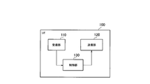
- FIG. 2 is a diagram showing the configuration of the UE 100 (user device).
- the UE 100 includes a receiving unit 110, a transmitting unit 120, and a control unit 130.
- the receiving unit 110 performs various receptions under the control of the control unit 130.
- the receiving unit 110 includes an antenna and a receiver.
- the receiver converts the radio signal received by the antenna into a baseband signal (received signal) and outputs it to the control unit 130.
- the transmission unit 120 performs various transmissions under the control of the control unit 130.
- the transmitter 120 includes an antenna and a transmitter.
- the transmitter converts the baseband signal (transmission signal) output by the control unit 130 into a radio signal and transmits it from the antenna.
- the control unit 130 performs various controls on the UE 100.
- the control unit 130 includes at least one processor and at least one memory.
- the memory stores a program executed by the processor and information used for processing by the processor.
- the processor may include a baseband processor and a CPU (Central Processing Unit).
- the baseband processor modulates / demodulates and encodes / decodes the baseband signal.
- the CPU executes a program stored in the memory to perform various processes.
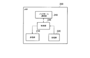
- FIG. 3 is a diagram showing the configuration of gNB200 (base station).
- the gNB 200 includes a transmission unit 210, a reception unit 220, a control unit 230, and a backhaul communication unit 240.
- the transmission unit 210 performs various transmissions under the control of the control unit 230.
- the transmitter 210 includes an antenna and a transmitter.
- the transmitter converts the baseband signal (transmission signal) output by the control unit 230 into a radio signal and transmits it from the antenna.
- the receiving unit 220 performs various receptions under the control of the control unit 230.
- the receiving unit 220 includes an antenna and a receiver.
- the receiver converts the radio signal received by the antenna into a baseband signal (received signal) and outputs it to the control unit 230.
- the control unit 230 performs various controls on the gNB 200.
- the control unit 230 includes at least one processor and at least one memory.
- the memory stores a program executed by the processor and information used for processing by the processor.
- the processor may include a baseband processor and a CPU.
- the baseband processor modulates / demodulates and encodes / decodes the baseband signal.
- the CPU executes a program stored in the memory to perform various processes.
- the backhaul communication unit 240 is connected to an adjacent base station via an interface between base stations.
- the backhaul communication unit 240 is connected to the AMF / UPF 300 via the base station-core network interface.
- the gNB is composed of a CU (Central Unit) and a DU (Distributed Unit) (that is, the functions are divided), and both units may be connected by an F1 interface.
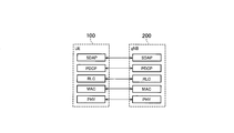
- FIG. 4 is a diagram showing a configuration of a protocol stack of a user plane wireless interface that handles data.
- the wireless interface protocol of the user plane includes a physical (PHY) layer, a MAC (Medium Access Control) layer, an RLC (Radio Link Control) layer, a PDCP (Packet Data Convergence Protocol) layer, and the like. It has an SDAP (Service Data Application Protocol) layer.
- PHY physical
- MAC Medium Access Control
- RLC Radio Link Control
- PDCP Packet Data Convergence Protocol
- SDAP Service Data Application Protocol
- the PHY layer performs coding / decoding, modulation / demodulation, antenna mapping / demapping, and resource mapping / demapping. Data and control information are transmitted between the PHY layer of the UE 100 and the PHY layer of the gNB 200 via a physical channel.
- the MAC layer performs data priority control, retransmission processing by hybrid ARQ (HARQ), random access procedure, and the like. Data and control information are transmitted between the MAC layer of the UE 100 and the MAC layer of the gNB 200 via the transport channel.
- the MAC layer of gNB200 includes a scheduler. The scheduler determines the transport format (transport block size, modulation / coding method (MCS)) of the upper and lower links and the resource block allocated to the UE 100.
- MCS modulation / coding method
- the RLC layer transmits data to the receiving RLC layer by using the functions of the MAC layer and the PHY layer. Data and control information are transmitted between the RLC layer of the UE 100 and the RLC layer of the gNB 200 via a logical channel.
- the PDCP layer performs header compression / decompression and encryption / decryption.
- the SDAP layer maps the IP flow, which is a unit for which the core network performs QoS control, with the wireless bearer, which is a unit for which AS (Access Stratum) controls QoS.
- the SDAP may be omitted.
- FIG. 5 is a diagram showing a configuration of a protocol stack of a wireless interface of a control plane that handles signaling (control signal).
- the protocol stack of the radio interface of the control plane has an RRC (Radio Resource Control) layer and a NAS (Non-Access Stratum) layer in place of the SDAP layer shown in FIG.
- RRC signaling for various settings is transmitted between the RRC layer of UE100 and the RRC layer of gNB200.
- the RRC layer controls the logical, transport, and physical channels as the radio bearer is established, reestablished, and released.
- RRC connection connection between the RRC of the UE 100 and the RRC of the gNB 200
- the UE 100 is in the RRC connected mode. If there is no connection (RRC connection) between the RRC of the UE 100 and the RRC of the gNB 200, the UE 100 is in RRC idle mode.
- the NAS layer located above the RRC layer performs session management, mobility management, etc.
- NAS signaling is transmitted between the NAS layer of the UE 100 and the NAS layer of the AMF 300.
- the UE 100 has an application layer and the like in addition to the wireless interface protocol.
- FIG. 6 is a diagram showing an assumed scenario.
- a scenario is assumed in which a relay UE 100-2 intervenes in the communication between the gNB 200-1 and the remote UE 100-1, and a side link relay is used to relay the communication.
- the remote UE 100-1 performs wireless communication (side link communication) with the relay UE 100-2 on the PC5 interface (side link), which is an interface between UEs.
- the relay UE 100-2 performs wireless communication (Uu communication) with gNB200-1 on the NR Uu wireless interface.
- Uu communication includes uplink communication and downlink communication.
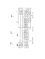
- FIG. 7 is a diagram showing an example of the protocol stack in the assumed scenario.
- the MAC layer and the PHY layer which are lower layers of the RLC layer, are not shown.
- gNB200-1 may be divided into CU and DU.
- An F1-C interface (Intra-donor F1-C) is established between the CU and the DU.
- the PDCP layer of the CU of gNB200-1 and the PDCP layer of the remote UE100-1 communicate with each other via the relay UE100-2.
- the RRC layer of the CU and the RRC layer of the remote UE 100-1 also communicate with each other via the relay UE 100-2.
- an adaptation layer may be provided as an upper layer of the RLC layer.
- the RRC layer of the CU and the RRC layer of the relay UE 100-2 communicate with each other.
- the PDCP layer of the CU and the PDCP layer of the relay UE 100-2 communicate with each other.
- each of the remote UE 100-1 and the relay UE 100-2 may have an RRC layer for PC5.
- RRC layer is called "PC5 RRC”.
- FIG. 8 is a diagram showing an example of a protocol stack having a PC5 RRC layer.
- FIG. 9 is a diagram showing another example of a protocol stack having a PC5 RRC layer. 8 and 9 show an example in which gNB200-1 is not separated into DU and CU, but gNB200-1 may be separated into DU and CU.
- the gNB200-1 is an RRC layer, a PDCP layer (Uu), an RLC layer (Uu), a MAC layer (Uu), and a PHY layer (Uu) used for communication (Uu communication) on the Uu interface.
- gNB200-1 has an adaptation layer between the PDCP layer (Uu) and the RLC layer (Uu).
- the relay UE 100-2 has an RRC layer (not shown), an RLC layer (Uu), a MAC layer (Uu), and a PHY layer (Uu) used for communication (Uu communication) on the Uu interface. Further, the relay UE 100-2 has a PC5 RRC layer, a PDCP layer (PC5), an RLC layer (PC5), a MAC layer (PC5), and a PHY layer (PC5) used for communication on the PC5 interface (PC5 communication). Further, the relay UE 100-2 has an adaptation layer as a layer higher than the PC5 RRC layer.
- the remote UE 100-1 has an RRC layer and a PDCP layer (Uu) used for communication on the Uu interface (Uu communication). Further, the remote UE 100-1 has a PC5 RRC layer, a PDCP layer (PC5), an RLC layer (PC5), a MAC layer (PC5), and a PHY layer (PC5) used for communication on the PC5 interface (PC5 communication). Further, the remote UE 100-1 has an adaptation layer between the PDCP layer (Uu) and the PC5 RRC layer.
- the remote UE 100-1 does not have to have an adaptation layer.
- the adaptation layer of the relay UE 100-2 is positioned as a higher layer of the RLC layer (Uu).
- Operation pattern 1 In this operation pattern 1, a step of establishing a connection between the remote UE 100-1 and the relay UE 100-2 and a step of performing a random access procedure for establishing a connection between the remote UE 100-1 and the gNB 200-1 are performed. And have.
- the step of performing the random access procedure includes a surrogate operation step in which the relay UE 100-2 performs at least a part of the operations performed by the MAC layer in the random access procedure instead of the remote UE 100-1.
- the remote UE 100-1 has a MAC layer of the PC5 interface, but does not have a MAC layer of the Uu interface.
- Random access procedures include actions that the MAC layer of the Uu interface should perform. Therefore, in order to establish a connection between the remote UE 100-1 and gNB 200-1 by performing at least a part of the operations performed by the MAC layer in the random access procedure by the relay UE 100-2 instead of the remote UE 100-1. Makes the random access procedure feasible.
- FIG. 10 is a diagram showing an operation pattern 1 of an operation of establishing an RRC connection between the remote UE 100-1 and the gNB 200-1. In FIG. 10, the non-essential steps are shown by broken lines.
- step S101 the remote UE 100-1 and the relay UE 100-2 establish a PC5 RRC connection.
- the PC5 RRC connection means a connection established between the PC5 RRC layer of the remote UE 100-1 and the PC5 RRC layer of the relay UE 100-2.
- the RRC connection may not yet be established between the relay UE 100-2 and the gNB 200-1.
- the relay UE 100-2 can relay the traffic of the remote UE 100-1 to the gNB 200-1 in the PC5 RRC connection.
- the remote UE 100-1 notifies the relay UE 100-2 of the relay request, and the relay UE 100-2 accepts the relay request.
- the relay UE 100-2 permits the remote UE 100-1 to communicate with the traffic to be relayed.
- Such a confirmation operation can be applied to each operation pattern described later.
- the remote UE 100-1 decides to carry out the RRC connection establishment process with the gNB 200-1. For example, in response to a connection establishment request from an upper layer (NAS layer), the RRC layer generates a message (RRC Setup Request, RRC Request Request or RRC Request Request) for establishing an RRC connection, and the generated message is generated as a lower layer. To provide. In such cases, the remote UE 100-1 usually triggers a random access procedure for gNB200-1. On the other hand, when the relay UE 100-2 relays, the remote UE 100-1 does not use the Uu MAC entity because it communicates using the PC5 MAC entity. That is, the Uu MAC entity does not need to perform a random access procedure.
- NAS layer an upper layer
- the RRC layer In response to a connection establishment request from an upper layer (NAS layer), the RRC layer generates a message (RRC Setup Request, RRC Request Request or RRC Request Request) for establishing an RRC connection, and the generated message is generated as a lower
- the remote UE 100-1 decides not to trigger the random access procedure. That is, the remote UE 100-1 triggers a random access procedure when the RRC connection is established (restarted), when the MAC entity associated with Uu is not used and / or when the MAC entity associated with the PC5 to be relayed is used. Decide not to.
- the remote UE 100-1 may further decide to send a proxy request message requesting a proxy operation to the relay UE 100-2.
- the remote UE 100-1 transmits a proxy request message requesting a proxy operation to the relay UE 100-2.
- the proxy request message may be a message requesting the relay UE 100-2 to send a random access preamble to the gNB200-1.
- the proxy request message is a message transmitted from a predetermined layer of the remote UE 100-1 to a predetermined layer of the relay UE 100-2.
- the predetermined layer is a MAC layer (PC5), an RLC layer (PC5), a PDCP layer (PC5), a PC5 RRC layer, or an adaptation layer.
- step S103 the relay UE 100-2 transmits a random access preamble to the gNB 200-1 in response to the reception of the proxy request message.
- the random access preamble is transmitted from the MAC layer (Uu) of the relay UE 100-2 to the MAC layer (Uu) of the gNB200-1.
- the random access preamble constitutes the first message (called "Msg1") in the random access procedure.
- the relay UE 100-2 may transmit a random access preamble to gNB200-1 according to the establishment of the PC5 RRC connection (step S101) even if the relay UE 100-2 has not received the proxy request message. If the relay UE 100-2 has already established an RRC connection with the gNB 200-1, steps S103 and S104 may be omitted, and the response message of step S105 may be transmitted from the relay UE 100-2 to the remote UE 100-1. good.
- the gNB 200-1 transmits a random access response to the relay UE 100-2.
- the relay UE 100-2 receives the random access response.
- the random access response is transmitted from the MAC layer (Uu) of gNB200-1 to the MAC layer (Uu) of the relay UE 100-2.
- the random access response constitutes a second message (called "Msg2") in the random access procedure.
- the random access response includes an uplink grant indicating the uplink radio resource assigned to the relay UE 100-2 by gNB200-1 and a timing advance value for adjusting the uplink transmission timing of the relay UE 100-2.
- the transmission / reception of Msg1 in step S103 and the transmission / reception of Msg2 in step S104 correspond to the operations performed by the MAC layer in the random access procedure.
- the relay UE 100-2 transmits a response message (ACK) to the proxy request message to the remote UE 100-1 in response to receiving the random access response from the gNB 200-1.
- the response message is a message transmitted from the predetermined layer of the relay UE 100-2 to the predetermined layer of the remote UE 100-1.
- the predetermined layer is a MAC layer (PC5), an RLC layer (PC5), a PDCP layer (PC5), a PC5 RRC layer, or an adaptation layer.
- the response message may be transmitted when the PC5 RRC connection in step S101 is established. For example, when the relay UE 100-2 has already established the RRC connection with the gNB 200-1 and completes the RRC connection establishment process with the remote UE 100-1, and / or when the relay operation is executed (permitted).
- the response message may be sent.
- the remote UE 100-1 sends an RRC message for the remote UE 100-1 to connect to the gNB 200-1 in response to the reception of the response message from the relay UE 100-2 via the relay UE 100-2.
- Such an RRC message constitutes a third message (referred to as "Msg3") in the random access procedure.
- the RRC message shall be an RRC setup request message requesting the establishment of an RRC connection.
- the RRC message may be an RRC reestablishment request message requesting the reestablishment of the RRC connection, or an RRC recovery request message requesting the restoration of the interrupted RRC connection.
- the gNB 200-1 transmits an RRC message to the remote UE 100-1 via the relay UE 100-2 in response to the reception of Msg3 from the remote UE 100-1.
- RRC message constitutes a fourth message (referred to as "Msg4") in the random access procedure.
- the RRC message shall be an RRC setup message.
- the RRC message may be an RRC reestablishment message or an RRC recovery message.
- the remote UE 100-1 transmits an RRC message to the gNB 200-1 via the relay UE 100-2 in response to the reception of Msg4 from the gNB 200-1.
- RRC message constitutes a fifth message (referred to as "Msg5") in the random access procedure.
- the RRC message shall be an RRC setup completion message.
- the RRC message may be an RRC reestablishment completion message or an RRC restoration completion message.
- step S109 an RRC connection is established (or reestablished or restored) between the remote UE 100-1 and gNB 200-1.
- (1.2) Operation pattern 2 In this operation pattern 2, the step of establishing a connection between the remote UE 100-1 and the relay UE 100-2 and the RRC message for the remote UE 100-1 to connect to the gNB 200-1 are transmitted from the remote UE 100-1 to the relay UE 100-. It has a step of transmitting to gNB200-1 via 2.
- the step of transmitting the RRC message includes a step of transmitting an RRC message including information (hereinafter, referred to as “remote information”) indicating that the RRC message has been transmitted via the relay UE 100-2.
- the RRC message including the remote information is Msg3 or Msg5, but an example in which the remote information is included in Msg3 will be mainly described below.
- the relay UE 100-2 is transparent from the viewpoint of the RRC connection between the gNB 200-1 and the remote UE 100-1, and the RRC layer (Uu) of the gNB 200-1 is the Msg3 (Uu) received by itself. Or, it is difficult to grasp whether or not Msg5) has been sent via the relay UE 100-2. Therefore, when the remote UE 100-1 transmits Msg3 (or Msg5) including the remote information to the gNB200-1, the gNB200-1 can appropriately grasp whether or not the connection request is made via the relay UE100-2. ..
- the step of transmitting the RRC message omits the transmission / reception of the random access preamble (Msg1) and the transmission / reception of the random access response (Msg2), and transmits the RRC message from the remote UE 100-1 via the relay UE 100-2. May include the step of transmitting to gNB200-1. That is, unlike the operation pattern 1 described above, the operation pattern 2 may not require transmission / reception of Msg1 and transmission / reception of Msg2.
- FIG. 11 is a diagram showing an operation pattern 2 of an operation of establishing an RRC connection between the remote UE 100-1 and the gNB 200-1. In FIG. 11, the non-essential steps are shown by broken lines.
- step S201 the relay UE 100-2 establishes an RRC connection with the gNB 200-1.
- step S202 the remote UE 100-1 and the relay UE 100-2 establish a PC5 RRC connection. Step S202 may be performed before step S201.
- the remote UE 100-1 transmits an RRC message (Msg3) for the remote UE 100-1 to connect to the gNB 200-1 to the gNB 200-1 via the relay UE 100-2.
- RRC message constitutes a third message (referred to as "Msg3") in the random access procedure.
- Such an RRC message shall be an RRC setup request message requesting the establishment of an RRC connection.
- the RRC message may be an RRC reestablishment request message requesting the reestablishment of the RRC connection, or an RRC recovery request message requesting the restoration of the interrupted RRC connection.
- the remote UE 100-1 may transmit an RRC message (Msg3) including remote information indicating that the RRC message has been transmitted via the relay UE 100-2.
- the remote information may be a flag that becomes "1" when passing through the relay UE 100-2, and "0" in other cases.
- the remote information may be included in the cause field (Cause field) of the RRC message (Msg3).
- the remote information may be an identifier indicating the relay UE 100-2, for example, a C-RNTI (Cell-Radio Network Strength Identity) of the relay UE 100-2.
- the C-RNTI may be notified in advance (for example, in S202) from the relay UE 100-2 to the remote UE 100-1.
- step S204 the gNB 200-1 transmits an RRC message (Msg4) to the remote UE 100-1 via the relay UE 100-2 in response to the reception of the Msg 3 from the remote UE 100-1.
- RRC message shall be an RRC setup message.
- the RRC message may be an RRC reestablishment message or an RRC recovery message.
- step S205 the remote UE 100-1 transmits an RRC message (Msg5) to the gNB 200-1 via the relay UE 100-2 in response to the reception of the Msg 4 from the gNB 200-1.
- RRC message shall be an RRC setup completion message.
- the RRC message may be an RRC reestablishment completion message or an RRC restoration completion message.
- the remote UE 100-1 may transmit an RRC message (Msg5) including remote information indicating that the RRC message has been transmitted via the relay UE 100-2.
- the remote UE 100-1 may transmit the RRC message (Msg5) including the remote information without transmitting the RRC message (Msg3) including the remote information.
- the remote information may be included in the cause field (Cause field) of the RRC message (Msg5).
- step S206 an RRC connection is established (or reestablished or restored) between the remote UE 100-1 and gNB 200-1.
- the gNB 200-1 is transmitted via the relay UE 100-2. It can be grasped that it is a connection request in. As a result, the gNB 200-1 can appropriately control the remote UE 100-1 at the RRC layer.
- gNB200-1 sets the timer setting value of the PDCP layer or RRC layer longer than the normal setting value by the RRC resetting message transmitted to the remote UE100-1 after the RRC connection with the remote UE100-1 is established. do.
- the gNB 200-1 may implement the routing setting of the remote UE 100-1 (for example, associating a logical channel) with respect to the adaptation layer of the relay UE 100-2. ..
- the gNB 200-1 uses the RRC reset message transmitted to the remote UE 100-1 or the relay UE 100-2 to transmit the RLC layer (PC5), the MAC layer (PC5), and the MAC layer (PC5).
- the PHY layer (PC5) can be set appropriately.
- the gNB 200-1 may not include the RLC setting, MAC setting, and PHY setting of the Uu interface in the RRC reset message transmitted to the remote UE 100-1. Specifically, the gNB 200-1 that has received the RRC message including the remote information does not include the PHY, MAC, and RLC setting information in the RRC reset message. On the other hand, the gNB200-1 that has received the RRC message that does not include the remote information includes the PHY, MAC, and RLC setting information in the RRC reset message.
- the operations related to the RRC message from the gNB200-1 to the remote UE100-1 include a step in which the remote UE100-1 receives an RRC message from the gNB200-1 via the relay UE100-2, and the remote UE100-1 is the content of the RRC message. It has a step of performing a notification operation for notifying the relay UE 100-2.
- the relay UE 100-2 cannot interpret the contents of the RRC message sent and received by the gNB 200-1 and the remote UE 100-1 via the relay UE 100-2. Therefore, when the remote UE 100-1 performs a notification operation of notifying the relay UE 100-2 of the content of the RRC message received from the gNB 200-1, the relay UE 100-2 can grasp the content of the RRC message.
- the RRC message received by the remote UE 100-1 from the gNB 200-1 via the relay UE 100-2 is an RRC release message.
- Such an RRC release message is a message that releases or interrupts the RRC connection between the remote UE 100-1 and the gNB 200-1.
- the RRC release message may be a message for interrupting the RRC connection. ..
- "release" of the RRC connection may be read as "interruption" of the RRC connection.
- FIG. 12 is a diagram showing an operation pattern 1 regarding an RRC message from the gNB 200-1 to the remote UE 100-1.
- the non-essential steps are shown by broken lines.
- step S301 the relay UE 100-2 establishes an RRC connection with the gNB 200-1.
- step S302 the remote UE 100-1 and the relay UE 100-2 establish a PC5 RRC connection. Step S302 may be performed before step S301.
- step S303 the remote UE 100-1 establishes an RRC connection with the gNB 200-1.
- step S304 the gNB 200-1 transmits an RRC release message to the remote UE 100-1 via the relay UE 100-2.
- the gNB 200-1 may include the designation information of whether or not the remote UE 100-1 should stay under the relay UE 100-2 in the RRC release message.
- gNB200-1 may specify whether the PC5 RRC connection should be maintained or the cell (gNB200-1 etc.) should be reselected.
- the remote UE 100-1 determines the standby operation after the RRC connection is released according to the instruction of the designated information. For example, the remote UE 100-1 determines an operation that prioritizes the cell reselection operation.
- the priority is an operation such as raising the priority of the cell, lowering the priority of maintaining the PC5 connection (or releasing the PC5 connection), and / or applying an offset in the reselection determination.
- step S305 the remote UE 100-1 releases the RRC connection with gNB200-1 in response to receiving the RRC release message from gNB200-1.
- the remote UE 100-1 transmits a notification indicating reception of the RRC release message and / or release of the RRC connection with the gNB 200-1 to the relay UE 100-2.
- a notification is a message transmitted from a predetermined layer of the remote UE 100-1 to a predetermined layer of the relay UE 100-2.
- the predetermined layer is a MAC layer (PC5), an RLC layer (PC5), a PDCP layer (PC5), a PC5 RRC layer, or an adaptation layer.
- the remote UE 100-1 may release the PC5 RRC connection with the relay UE 100-2 in response to receiving the RRC release message or releasing the RRC connection with the gNB200-1.
- the relay UE 100-2 considers that the RRC connection with the gNB200-1 has been released in response to the release of the PC5 RRC connection.
- step S307 the relay UE 100-2 releases the RRC connection with the gNB 200-1 in response to the notification from the remote UE 100-1.
- the RRC message received by the remote UE 100-1 from the gNB 200-1 via the relay UE 100-2 includes setting information used for communication control between the relay UE 100-2 and the gNB 200-1.
- the remote UE 100-1 transmits the setting information included in this RRC message to the relay UE 100-2.
- the RRC message may further include setting information used for communication control between the remote UE 100-1 and the relay UE 100-2 (that is, setting information for the PC5 interface).
- the gNB 200-1 can both reconfigure the RRC of the remote UE 100-1 and reconfigure the RRC of the relay UE 100-2 by one RRC message transmitted to the remote UE 100-1.
- FIG. 13 is a diagram showing an operation pattern 1 regarding an RRC message from the gNB 200-1 to the remote UE 100-1.
- the non-essential steps are shown by broken lines.
- step S401 the relay UE 100-2 establishes an RRC connection with the gNB 200-1.
- step S402 the remote UE 100-1 and the relay UE 100-2 establish a PC5 RRC connection. Step S402 may be performed before step S401.
- step S403 the remote UE 100-1 establishes an RRC connection with the gNB 200-1.
- the gNB 200-1 transmits an RRC message to the remote UE 100-1 via the relay UE 100-2.
- RRC messages are, for example, RRC setup messages, RRC recovery messages, RRC reestablishment messages, or RRC reconfiguration messages.
- the RRC message includes Uu's RLC / MAC / PHY setting information.
- the RLC / MAC / PHY setting information may include CellGroupConfig, which is setting information indicating the setting of the cell group in the Uu interface, or may include setting information (for example, routing information, etc.) for the adaptation layer of the relay UE 100-2. ..
- the remote UE 100-1 When the RRC message further includes the setting information for the PC5 interface, the remote UE 100-1 that has received the RRC message reconfigures the RRC on the PC5 interface using this setting information.
- the remote UE 100-1 transmits a message including the RLC / MAC / PHY setting information of Uu included in the RRC message to the relay UE 100-2.
- a message is a message transmitted from a predetermined layer of the remote UE 100-1 to a predetermined layer of the relay UE 100-2.
- the predetermined layer is a MAC layer (PC5), an RLC layer (PC5), a PDCP layer (PC5), a PC5 RRC layer, or an adaptation layer.
- the relay UE 100-2 reconfigures the RRC on the Uu interface using the RLC / MAC / PHY setting information of the Uu.
- step S406 the relay UE 100-2 transmits an acknowledgment message (ACK) to the remote UE 100-1.
- ACK acknowledgment message
- the remote UE 100-1 transmits an RRC completion message to the gNB 200-1 via the relay UE 100-2 in response to receiving the acknowledgment message (ACK).
- the RRC completion message is, for example, an RRC setup completion message, an RRC restoration completion message, an RRC reestablishment completion message, or an RRC resetting completion message.
- the relay UE 100-2 If the relay UE 100-2 fails to reset the RRC using the Uu RLC / MAC / PHY setting information, the relay UE 100-2 transmits a negative response message (NACK) instead of the acknowledgment message (ACK) to the remote UE 100-1. You may.
- the remote UE 100-1 may consider that the RRC resetting has failed and start the RRC reestablishment process. In this RRC reestablishment process, the remote UE 100-1 failed to reconfigure the RRC in the relay UE 100-2 in the Case field in the RRC reestablishment request message transmitted to the reconnection destination (for example, gNB200-2). Information indicating that may be included.
- FIG. 14 is a diagram showing a signaling radio bearer according to an embodiment.
- the remote UE 100-1 has an RRC layer (Uu) and a PC5 RRC layer.
- the RRC layer (Uu) and the PC5 RRC layer may be separate RRC entities or may be separate functions in one RRC entity.
- the RRC layer (Uu) of the remote UE 100-1 sends the first RRC message used for communication control with the gNB 200-1 on the first signaling radio bearer (SRB (A)) via the relay UE 100-2 to the gNB 200-1. Send and receive with the RRC layer (Uu).
- the PC5 RRC layer of the remote UE 100-1 transmits the second RRC message used for communication control with the relay UE 100-2 on the second signaling radio bearer (SRB (B)) different from the first signaling radio bearer.
- SRB (B) the second signaling radio bearer
- the signaling radio bearer number of the second signaling radio bearer (SRB (B)) is different from the signaling radio bearer number of the first signaling radio bearer (SRB (A)).
- the first signaling radio bearer and the second signaling radio bearer may be the same signaling radio bearer.
- the RRC layer (Uu) of the remote UE 100-1 may send and receive the first RRC message used for communication control with the gNB 200-1 by including it in the second RRC message used for communication control with the relay UE 100-2. ..
- One remote UE 100-1 may connect to a plurality of relay UEs 100-2, or a plurality of remote UEs 100-1 may connect to one relay UE 100-2. Therefore, it is desirable to be able to specify which remote UE 100-1 and which relay UE 100-2 are to measure the radio state of the radio link.
- the radio state to be measured may be received power, for example, RSSI (Received Signal Strength Indicator), or may be congestion degree for each predetermined frequency unit, for example, CBR (Cannel Busy Ratio).
- the gNB 200-1 receives the link identification information that identifies the wireless link between the remote UE 100-1 and the relay UE 100-2 from the remote UE 100-1 or the relay UE 100-2.
- the gNB 200-1 controls the measurement of the radio state between the remote UE 100-1 and the relay UE 100-2 based on the link identification information.
- link specific information for example, a destination identifier that identifies a destination in side link communication (hereinafter, referred to as "side link destination identifier") can be used.
- the side link destination identifier may be the Destination Layer-2 ID.
- Such a side link destination identifier may be an identifier assigned by an entity (ProSe function) of the core network.
- routing information may be used as link specific information. That is, the link is specified by the route setting.
- BAP backhaul adaptation protocol
- the link may be specified by a Routing ID, Path ID, BAP Address, or the like.
- the link identification information may include an access point identifier.
- FIG. 15 is a diagram showing an operation pattern 1 of a wireless state measurement operation between the remote UE 100-1 and the relay UE 100-2 according to the embodiment. In FIG. 15, the non-essential steps are shown by broken lines.
- step S501 the relay UE 100-2 establishes an RRC connection with the gNB 200-1.
- step S502 the remote UE 100-1 and the relay UE 100-2 establish a PC5 RRC connection.
- Step S502 may be performed before step S501.
- step S503 the remote UE 100-1 establishes an RRC connection with the gNB 200-1.
- step S504 the relay UE 100-2 transmits the side link destination identifier (link specific information) assigned to the relay UE 100-2 to the gNB 200-1.
- the gNB 200-1 transmits an RRC message including the measurement setting to the remote UE 100-1 via the relay UE 100-2.
- This measurement setting includes a side link destination identifier (link specific information) assigned to the relay UE 100-2.
- the measurement settings may further include trigger conditions for the measurement report. This trigger condition may include a threshold to be compared with the radio state of the side link.
- the remote UE 100-1 measures the radio state with the relay UE 100-2 (that is, the radio state of the side link) based on the measurement setting received from the gNB 200-1. Specifically, the remote UE 100-1 determines that the measurement is performed on the relay UE 100-2 based on the side link destination identifier (link specific information) included in the measurement setting, and measures the relay UE 100-2. ..
- the remote UE 100-1 transmits an RRC message including a measurement report to the gNB 200-1 via the relay UE 100-2.
- the remote UE 100-1 may transmit an RRC message including a measurement report when the trigger condition set in the measurement setting is satisfied.
- the measurement report includes the measurement result in step S506 and the side link destination identifier (link specific information) corresponding to this measurement result.
- the gNB 200 can specify which relay UE 100-2 is the measurement result based on the side link destination identifier (link identification information) included in the measurement report.
- FIG. 16 is a diagram showing an operation pattern 2 of a wireless state measurement operation between the remote UE 100-1 and the relay UE 100-2 according to the embodiment. In FIG. 16, the non-essential steps are shown by broken lines.
- step S601 the relay UE 100-2 establishes an RRC connection with the gNB 200-1.
- step S602 the remote UE 100-1 and the relay UE 100-2 establish a PC5 RRC connection. Step S602 may be performed before step S601.
- step S603 the remote UE 100-1 establishes an RRC connection with the gNB 200-1.
- the remote UE 100-1 transmits the side link destination identifier (link specific information) assigned to the remote UE 100-1 to the gNB 200-1.
- the remote UE 100-1 may include the side link destination identifier in Msg3 or Msg5 and transmit it to gNB200-1, or may include the sidelink destination identifier in the UE auxiliary information message and transmit it to gNB200-1. good.
- the gNB 200-1 transmits an RRC message including the measurement setting to the relay UE 100-2.
- This measurement setting includes a side link destination identifier (link specific information) assigned to the remote UE 100-1.
- the measurement settings may further include trigger conditions for the measurement report. This trigger condition may include a threshold to be compared with the radio state of the side link.
- the relay UE 100-2 measures the wireless state with the remote UE 100-1 (that is, the wireless state of the side link) based on the measurement setting received from the gNB 200-1. Specifically, the relay UE 100-2 determines that the measurement is performed on the remote UE 100-1 based on the side link destination identifier (link specific information) included in the measurement setting, and performs the measurement on the remote UE 100-1. ..
- the relay UE 100-2 transmits an RRC message including a measurement report to gNB200-1.
- the relay UE 100-2 may transmit an RRC message including a measurement report when the trigger condition set in the measurement setting is satisfied.
- the measurement report includes the measurement result in step S606 and the side link destination identifier (link specific information) corresponding to this measurement result.
- the gNB 200 can specify which remote UE 100-1 is the measurement result based on the side link destination identifier (link identification information) included in the measurement report.
- the operation in the relay UE 100-2 has been mainly described, but the operation according to the above-described embodiment may be applied to the IAB (Integrated Access and Backhaul) node which is a wireless relay node.
- the IAB node may perform the operation of the relay UE 100-2 described in the above-described embodiment.
- the “relay UE” of the above-described embodiment may be read as “IAB node”, and the “side link” of the above-described embodiment may be read as “access link”.
- the PC5 RRC connection may be read as an RRC connection with an IAB node or an RRC connection with an IAB donor.
- a program that causes the computer to execute each process performed by the UE 100 or the gNB 200 may be provided.
- the program may be recorded on a computer-readable medium.
- Computer-readable media allow you to install programs on your computer.
- the computer-readable medium on which the program is recorded may be a non-transient recording medium.
- the non-transient recording medium is not particularly limited, but may be, for example, a recording medium such as a CD-ROM or a DVD-ROM.
- a circuit that executes each process performed by the UE 100 or the gNB 200 may be integrated, and at least a part of the UE 100 or the gNB 200 may be configured as a semiconductor integrated circuit (chipset, SoC).
Landscapes
- Engineering & Computer Science (AREA)
- Computer Networks & Wireless Communication (AREA)
- Signal Processing (AREA)
- Mobile Radio Communication Systems (AREA)
Abstract
Description
まず、一実施形態に係る移動通信システムの構成について説明する。図1は、一実施形態に係る移動通信システムの構成を示す図である。この移動通信システムは、3GPP規格の第5世代システム(5GS:5th Generation System)に準拠する。以下において、5GSを例に挙げて説明するが、移動通信システムにはLTE(Long Term Evolution)システムが少なくとも部分的に適用されてもよい。 (Configuration of mobile communication system)
First, the configuration of the mobile communication system according to the embodiment will be described. FIG. 1 is a diagram showing a configuration of a mobile communication system according to an embodiment. This mobile communication system complies with the 5th generation system (5GS: 5th Generation System) of the 3GPP standard. In the following, 5GS will be described as an example, but an LTE (Long Term Evolution) system may be applied to a mobile communication system at least partially.
次に、一実施形態に係る移動通信システム1における想定シナリオについて説明する。図6は、想定シナリオを示す図である。 (Assumed scenario)
Next, an assumed scenario in the mobile communication system 1 according to the embodiment will be described. FIG. 6 is a diagram showing an assumed scenario.
次に、一実施形態に係る移動通信システム1の動作について説明する。 (Operation of mobile communication system)
Next, the operation of the mobile communication system 1 according to the embodiment will be described.
遠隔UE100-1とgNB200-1とのRRC接続の確立動作について説明する。 (1) Operation for establishing RRC connection between remote UE and gNB The operation for establishing RRC connection between remote UE 100-1 and gNB200-1 will be described.
本動作パターン1は、遠隔UE100-1と中継UE100-2との間の接続を確立するステップと、遠隔UE100-1とgNB200-1との間の接続を確立するためのランダムアクセスプロシージャを行うステップとを有する。ランダムアクセスプロシージャを行うステップは、ランダムアクセスプロシージャにおいてMACレイヤが行う少なくとも一部の動作を遠隔UE100-1の代わりに中継UE100-2が行う代理動作ステップを含む。 (1.1) Operation pattern 1
In this operation pattern 1, a step of establishing a connection between the remote UE 100-1 and the relay UE 100-2 and a step of performing a random access procedure for establishing a connection between the remote UE 100-1 and the gNB 200-1 are performed. And have. The step of performing the random access procedure includes a surrogate operation step in which the relay UE 100-2 performs at least a part of the operations performed by the MAC layer in the random access procedure instead of the remote UE 100-1.
本動作パターン2は、遠隔UE100-1と中継UE100-2との間の接続を確立するステップと、遠隔UE100-1がgNB200-1と接続するためのRRCメッセージを遠隔UE100-1から中継UE100-2を介してgNB200-1に送信するステップとを有する。RRCメッセージを送信するステップは、中継UE100-2を介してRRCメッセージが送信されたことを示す情報(以下、「遠隔情報」と呼ぶ)を含むRRCメッセージを送信するステップを含む。ここで、遠隔情報を含むRRCメッセージがMsg3又はMsg5であるものとするが、以下において、Msg3に遠隔情報を含める一例について主として説明する。 (1.2) Operation pattern 2
In this operation pattern 2, the step of establishing a connection between the remote UE 100-1 and the relay UE 100-2 and the RRC message for the remote UE 100-1 to connect to the gNB 200-1 are transmitted from the remote UE 100-1 to the relay UE 100-. It has a step of transmitting to gNB200-1 via 2. The step of transmitting the RRC message includes a step of transmitting an RRC message including information (hereinafter, referred to as “remote information”) indicating that the RRC message has been transmitted via the relay UE 100-2. Here, it is assumed that the RRC message including the remote information is Msg3 or Msg5, but an example in which the remote information is included in Msg3 will be mainly described below.
次に、gNB200-1から遠隔UE100-1へのRRCメッセージに関する動作について説明する。 (2) Operation related to RRC message from gNB to remote UE Next, the operation related to RRC message from gNB200-1 to remote UE100-1 will be described.
本動作パターン1において、遠隔UE100-1がgNB200-1から中継UE100-2を介して受信するRRCメッセージは、RRC解放メッセージである。このようなRRC解放メッセージは、遠隔UE100-1とgNB200-1との間のRRC接続を解放又は中断するメッセージである。以下において、RRC解放メッセージが遠隔UE100-1とgNB200-1との間のRRC接続を解放するメッセージである一例について説明するが、RRC解放メッセージは、当該RRC接続を中断するメッセージであってもよい。この場合、以下の説明において、RRC接続の「解放」をRRC接続の「中断」と読み替えればよい。 (2.1) Operation pattern 1
In this operation pattern 1, the RRC message received by the remote UE 100-1 from the gNB 200-1 via the relay UE 100-2 is an RRC release message. Such an RRC release message is a message that releases or interrupts the RRC connection between the remote UE 100-1 and the gNB 200-1. In the following, an example in which the RRC release message is a message for releasing the RRC connection between the remote UE 100-1 and the gNB 200-1 will be described, but the RRC release message may be a message for interrupting the RRC connection. .. In this case, in the following description, "release" of the RRC connection may be read as "interruption" of the RRC connection.
本動作パターン2において、遠隔UE100-1がgNB200-1から中継UE100-2を介して受信するRRCメッセージは、中継UE100-2とgNB200-1との間の通信制御に用いる設定情報を含む。遠隔UE100-1は、このRRCメッセージに含まれる設定情報を中継UE100-2に送信する。 (2.2) Operation pattern 2
In this operation pattern 2, the RRC message received by the remote UE 100-1 from the gNB 200-1 via the relay UE 100-2 includes setting information used for communication control between the relay UE 100-2 and the gNB 200-1. The remote UE 100-1 transmits the setting information included in this RRC message to the relay UE 100-2.
次に、一実施形態に係るシグナリング無線ベアラについて説明する。図14は、一実施形態に係るシグナリング無線ベアラを示す図である。 (3) Signaling Radio Bearer Next, the signaling radio bearer according to the embodiment will be described. FIG. 14 is a diagram showing a signaling radio bearer according to an embodiment.
次に、一実施形態に係る遠隔UE100-1と中継UE100-2との間の無線状態の測定動作について説明する。 (4) Operation of Measuring Radio Status Between Remote UE and Relay UE Next, the operation of measuring the radio status between the remote UE 100-1 and the relay UE 100-2 according to the embodiment will be described.
図15は、一実施形態に係る遠隔UE100-1と中継UE100-2との間の無線状態の測定動作の動作パターン1を示す図である。図15において、必須ではないステップを破線で示している。 (4.1) Operation pattern 1
FIG. 15 is a diagram showing an operation pattern 1 of a wireless state measurement operation between the remote UE 100-1 and the relay UE 100-2 according to the embodiment. In FIG. 15, the non-essential steps are shown by broken lines.
図16は、一実施形態に係る遠隔UE100-1と中継UE100-2との間の無線状態の測定動作の動作パターン2を示す図である。図16において、必須ではないステップを破線で示している。 (4.2) Operation pattern 2
FIG. 16 is a diagram showing an operation pattern 2 of a wireless state measurement operation between the remote UE 100-1 and the relay UE 100-2 according to the embodiment. In FIG. 16, the non-essential steps are shown by broken lines.
上述した実施形態において、中継UE100-2における動作について主として説明したが、無線中継ノードであるIAB(Integrated Access and Backhaul)ノードに対して、上述した実施形態に係る動作を適用してもよい。具体的には、IABノードが、上述した実施形態で説明された中継UE100-2の動作を行ってもよい。このような実施形態においては、上述した実施形態の「中継UE」を「IABノード」に読み替え、上述した実施形態の「サイドリンク」を「アクセスリンク」に読み替えればよい。また、PC5 RRC接続は、IABノードとのRRC接続もしくはIABドナーとのRRC接続と読み替えればよい。 (Other embodiments)
In the above-described embodiment, the operation in the relay UE 100-2 has been mainly described, but the operation according to the above-described embodiment may be applied to the IAB (Integrated Access and Backhaul) node which is a wireless relay node. Specifically, the IAB node may perform the operation of the relay UE 100-2 described in the above-described embodiment. In such an embodiment, the “relay UE” of the above-described embodiment may be read as “IAB node”, and the “side link” of the above-described embodiment may be read as “access link”. Further, the PC5 RRC connection may be read as an RRC connection with an IAB node or an RRC connection with an IAB donor.
Claims (13)
- 基地局と遠隔ユーザ装置との間の通信を中継するための中継ユーザ装置を用いる通信制御方法であって、
前記遠隔ユーザ装置と前記中継ユーザ装置との間の接続を確立することと、
前記遠隔ユーザ装置と前記基地局との間の接続を確立するためのランダムアクセスプロシージャを行うことと、を有し、
前記ランダムアクセスプロシージャを行うことは、前記ランダムアクセスプロシージャにおいてMAC(Medium Access Control)レイヤが行う少なくとも一部の動作を前記遠隔ユーザ装置の代わりに前記中継ユーザ装置が行う代理動作を含む
通信制御方法。 A communication control method that uses a relay user device to relay communication between a base station and a remote user device.
Establishing a connection between the remote user device and the relay user device
Having a random access procedure for establishing a connection between the remote user device and the base station.
Performing the random access procedure is a communication control method including a proxy operation in which the relay user device performs at least a part of the operations performed by the MAC (Medium Access Control) layer in the random access procedure instead of the remote user device. - 前記代理動作を要求する代理要求メッセージを前記遠隔ユーザ装置から前記中継ユーザ装置に送信することをさらに有し、
前記代理動作は、
前記代理要求メッセージの受信に応じてランダムアクセスプリアンブルを前記中継ユーザ装置から前記基地局に送信することと、
前記中継ユーザ装置が前記基地局からランダムアクセス応答を受信することと、を含む
請求項1に記載の通信制御方法。 Further comprising transmitting a proxy request message requesting the proxy operation from the remote user device to the relay user device.
The surrogate operation is
In response to the reception of the proxy request message, the random access preamble is transmitted from the relay user device to the base station, and
The communication control method according to claim 1, wherein the relay user device receives a random access response from the base station. - 前記ランダムアクセス応答の受信に応じて、前記代理要求メッセージに対する応答メッセージを前記中継ユーザ装置から前記遠隔ユーザ装置に送信することと、
前記応答メッセージの受信に応じて、前記遠隔ユーザ装置が前記基地局と接続するためのRRCメッセージを前記遠隔ユーザ装置から前記中継ユーザ装置を介して前記基地局に送信することと、をさらに有する
請求項2に記載の通信制御方法。 In response to the reception of the random access response, the response message to the proxy request message is transmitted from the relay user device to the remote user device.
A claim further comprising transmitting an RRC message for the remote user device to connect to the base station from the remote user device to the base station via the relay user device in response to the reception of the response message. Item 2. The communication control method according to item 2. - 基地局と遠隔ユーザ装置との間の通信を中継するための中継ユーザ装置を用いる通信制御方法であって、
前記遠隔ユーザ装置と前記中継ユーザ装置との間の接続を確立することと、
前記遠隔ユーザ装置が前記基地局と接続するためのRRC(Radio Resource Control)メッセージを前記遠隔ユーザ装置から前記中継ユーザ装置を介して前記基地局に送信することと、を有し、
前記RRCメッセージを送信することは、前記中継ユーザ装置を介して前記RRCメッセージが送信されたことを示す情報を含む前記RRCメッセージを送信することを含む
通信制御方法。 A communication control method that uses a relay user device to relay communication between a base station and a remote user device.
Establishing a connection between the remote user device and the relay user device
The remote user device has an RRC (Radio Resource Control) message for connecting to the base station to be transmitted from the remote user device to the base station via the relay user device.
Transmission of the RRC message is a communication control method including transmitting the RRC message including information indicating that the RRC message has been transmitted via the relay user device. - 前記RRCメッセージは、RRC接続の確立を要求するRRCセットアップ要求メッセージ、前記RRC接続の再確立を要求するRRC再確立要求メッセージ、又は中断されたRRC接続の復旧を要求するRRC復旧要求メッセージである
請求項4に記載の通信制御方法。 The RRC message is an RRC setup request message requesting the establishment of an RRC connection, an RRC reestablishment request message requesting the reestablishment of the RRC connection, or an RRC recovery request message requesting the restoration of an interrupted RRC connection. Item 4. The communication control method according to item 4. - 前記RRCメッセージを送信することは、ランダムアクセスプリアンブルの送受信及びランダムアクセス応答の送受信を省略するとともに、前記RRCメッセージを前記遠隔ユーザ装置から前記中継ユーザ装置を介して前記基地局に送信することを含む
請求項4又は5に記載の通信制御方法。 Transmission of the RRC message includes omitting transmission / reception of a random access preamble and transmission / reception of a random access response, and transmitting the RRC message from the remote user device to the base station via the relay user device. The communication control method according to claim 4 or 5. - 基地局と遠隔ユーザ装置との間の通信を中継するための中継ユーザ装置を用いる通信制御方法であって、
前記遠隔ユーザ装置が前記中継ユーザ装置を介して前記基地局からRRC(Radio Resource Control)メッセージを受信することと、
前記遠隔ユーザ装置が、前記RRCメッセージの内容を前記中継ユーザ装置に通知する通知動作を行うことと、を有する
通信制御方法。 A communication control method that uses a relay user device to relay communication between a base station and a remote user device.
When the remote user device receives an RRC (Radio Resource Control) message from the base station via the relay user device,
A communication control method comprising the remote user device performing a notification operation for notifying the relay user device of the content of the RRC message. - 前記RRCメッセージは、RRC解放メッセージであり、
前記通知動作を行うことは、前記RRCメッセージの内容を前記中継ユーザ装置に通知することを含む
請求項7に記載の通信制御方法。 The RRC message is an RRC release message.
The communication control method according to claim 7, wherein performing the notification operation includes notifying the relay user device of the content of the RRC message. - 前記RRCメッセージは、前記中継ユーザ装置と前記基地局との間の通信制御に用いる設定情報を含み、
前記通知動作を行うことは、前記RRCメッセージに含まれる前記設定情報を前記遠隔ユーザ装置から前記中継ユーザ装置に送信することを含む
請求項7に記載の通信制御方法。 The RRC message includes setting information used for communication control between the relay user device and the base station.
The communication control method according to claim 7, wherein performing the notification operation includes transmitting the setting information included in the RRC message from the remote user device to the relay user device. - 前記RRCメッセージは、前記遠隔ユーザ装置と前記中継ユーザ装置との間の通信制御に用いる設定情報をさらに含む
請求項9に記載の通信制御方法。 The communication control method according to claim 9, wherein the RRC message further includes setting information used for communication control between the remote user device and the relay user device. - 基地局と遠隔ユーザ装置との間の通信を中継するための中継ユーザ装置を用いる通信制御方法であって、
前記遠隔ユーザ装置が、前記基地局との通信制御に用いる第1RRC(Radio Resource Control)メッセージを、第1シグナリング無線ベアラ上で前記中継ユーザ装置を介して前記基地局と送受信することと、
前記遠隔ユーザ装置が、前記中継ユーザ装置との通信制御に用いる第2RRCメッセージを、前記第1シグナリング無線ベアラと異なる第2シグナリング無線ベアラ上で前記中継ユーザ装置と送受信することと、を有する
通信制御方法。 A communication control method that uses a relay user device to relay communication between a base station and a remote user device.
The remote user device transmits and receives a first RRC (Radio Resource Control) message used for communication control with the base station to and from the base station via the relay user device on the first signaling radio bearer.
Communication control comprising transmitting and receiving a second RRC message used by the remote user device for communication control with the relay user device to and from the relay user device on a second signaling radio bearer different from the first signaling radio bearer. Method. - 基地局と遠隔ユーザ装置との間の通信を中継するための中継ユーザ装置を用いる通信制御方法であって、
前記遠隔ユーザ装置と前記中継ユーザ装置との間の無線リンクを特定するリンク特定情報を、前記遠隔ユーザ装置又は前記中継ユーザ装置から前記基地局が受信することと、
前記基地局が、前記リンク特定情報に基づいて、前記遠隔ユーザ装置と前記中継ユーザ装置との間の無線状態の測定を制御することと、を有する
通信制御方法。 A communication control method that uses a relay user device to relay communication between a base station and a remote user device.
The base station receives link identification information that identifies a wireless link between the remote user device and the relay user device from the remote user device or the relay user device.
A communication control method in which the base station controls measurement of a wireless state between the remote user device and the relay user device based on the link identification information. - 前記リンク特定情報は、サイドリンク通信における送信先を識別する送信先識別子を含む
請求項12に記載の通信制御方法。 The communication control method according to claim 12, wherein the link specific information includes a destination identifier that identifies a destination in side link communication.
Priority Applications (7)
| Application Number | Priority Date | Filing Date | Title |
|---|---|---|---|
| CN202180037901.6A CN115669214B (en) | 2020-03-26 | 2021-03-05 | Communication control method, user equipment and processor |
| EP24191702.0A EP4436311A2 (en) | 2020-03-26 | 2021-03-05 | Communication control method |
| CN202410333867.2A CN118250828A (en) | 2020-03-26 | 2021-03-05 | Communication control method |
| EP21777153.4A EP4110008B1 (en) | 2020-03-26 | 2021-03-05 | Communication control method |
| JP2022509490A JP7413507B2 (en) | 2020-03-26 | 2021-03-05 | Communication control method |
| US17/934,881 US20230017794A1 (en) | 2020-03-26 | 2022-09-23 | Communication control method |
| JP2023221621A JP2024029143A (en) | 2020-03-26 | 2023-12-27 | Communication control method, remote user device, system, processor, program, and network node |
Applications Claiming Priority (2)
| Application Number | Priority Date | Filing Date | Title |
|---|---|---|---|
| JP2020056518 | 2020-03-26 | ||
| JP2020-056518 | 2020-03-26 |
Related Child Applications (1)
| Application Number | Title | Priority Date | Filing Date |
|---|---|---|---|
| US17/934,881 Continuation US20230017794A1 (en) | 2020-03-26 | 2022-09-23 | Communication control method |
Publications (1)
| Publication Number | Publication Date |
|---|---|
| WO2021192918A1 true WO2021192918A1 (en) | 2021-09-30 |
Family
ID=77891306
Family Applications (1)
| Application Number | Title | Priority Date | Filing Date |
|---|---|---|---|
| PCT/JP2021/008641 WO2021192918A1 (en) | 2020-03-26 | 2021-03-05 | Communication control method |
Country Status (5)
| Country | Link |
|---|---|
| US (1) | US20230017794A1 (en) |
| EP (2) | EP4110008B1 (en) |
| JP (2) | JP7413507B2 (en) |
| CN (2) | CN115669214B (en) |
| WO (1) | WO2021192918A1 (en) |
Cited By (1)
| Publication number | Priority date | Publication date | Assignee | Title |
|---|---|---|---|---|
| US11601997B1 (en) * | 2021-08-25 | 2023-03-07 | Asustek Computer Inc. | Method and apparatus for a remote user equipment (UE) to support direct to indirect communication path switching in a wireless communication system |
Families Citing this family (2)
| Publication number | Priority date | Publication date | Assignee | Title |
|---|---|---|---|---|
| CN114449680A (en) * | 2020-11-06 | 2022-05-06 | 维沃移动通信有限公司 | Connection state establishing method, terminal, core network function and access network equipment |
| US11917698B2 (en) * | 2021-10-22 | 2024-02-27 | Qualcomm Incorporated | Integrated access and backhaul (IAB) backhaul adaption protocol (BAP) routing over sidelink |
Citations (1)
| Publication number | Priority date | Publication date | Assignee | Title |
|---|---|---|---|---|
| JP2020056518A (en) | 2018-09-28 | 2020-04-09 | ダイキン工業株式会社 | Heat exchanger |
Family Cites Families (4)
| Publication number | Priority date | Publication date | Assignee | Title |
|---|---|---|---|---|
| CN101841920B (en) * | 2009-03-17 | 2013-06-05 | 华为技术有限公司 | Radio relay system and communication method for radio relay system |
| CN108307472B (en) | 2016-08-12 | 2023-06-30 | 中兴通讯股份有限公司 | Communication method and device of equipment through system and communication system |
| CN110178441B (en) * | 2017-01-09 | 2022-12-30 | Lg 电子株式会社 | Method for connecting network by relay UE having connection with remote UE in wireless communication system and apparatus therefor |
| CN109417695B (en) * | 2017-01-10 | 2020-10-23 | 华为技术有限公司 | Communication path switching method and equipment |
-
2021
- 2021-03-05 CN CN202180037901.6A patent/CN115669214B/en active Active
- 2021-03-05 EP EP21777153.4A patent/EP4110008B1/en active Active
- 2021-03-05 CN CN202410333867.2A patent/CN118250828A/en active Pending
- 2021-03-05 JP JP2022509490A patent/JP7413507B2/en active Active
- 2021-03-05 EP EP24191702.0A patent/EP4436311A2/en active Pending
- 2021-03-05 WO PCT/JP2021/008641 patent/WO2021192918A1/en active Application Filing
-
2022
- 2022-09-23 US US17/934,881 patent/US20230017794A1/en active Pending
-
2023
- 2023-12-27 JP JP2023221621A patent/JP2024029143A/en active Pending
Patent Citations (1)
| Publication number | Priority date | Publication date | Assignee | Title |
|---|---|---|---|---|
| JP2020056518A (en) | 2018-09-28 | 2020-04-09 | ダイキン工業株式会社 | Heat exchanger |
Non-Patent Citations (7)
| Title |
|---|
| 3GPP CONTRIBUTION: "RP-193253", INTERNET, Retrieved from the Internet <URL:https://www.3gpp.org/ftp/tsg_ran/TSG_RAN/TSGR_86/Docs/RP-193253.zip> |
| COOLPAD: "Discussion on Signaling Radio Bearer Modelling for L2 Relay UE", 3GPP DRAFT; R2-1704553_SRB MODELING_V3, 3RD GENERATION PARTNERSHIP PROJECT (3GPP), MOBILE COMPETENCE CENTRE ; 650, ROUTE DES LUCIOLES ; F-06921 SOPHIA-ANTIPOLIS CEDEX ; FRANCE, vol. RAN WG2, no. Hangzhou, China; 20170515 - 20170519, 6 May 2017 (2017-05-06), Mobile Competence Centre ; 650, route des Lucioles ; F-06921 Sophia-Antipolis Cedex ; France , XP051264458 * |
| HUAWEI, HISILICON: "Paging and access", 3GPP DRAFT; R2-1701136, 3RD GENERATION PARTNERSHIP PROJECT (3GPP), MOBILE COMPETENCE CENTRE ; 650, ROUTE DES LUCIOLES ; F-06921 SOPHIA-ANTIPOLIS CEDEX ; FRANCE, vol. RAN WG2, no. Athens, Greece; 20170213 - 20170217, 4 February 2017 (2017-02-04), Mobile Competence Centre ; 650, route des Lucioles ; F-06921 Sophia-Antipolis Cedex ; France , XP051223387 * |
| LG ELECTRONICS INC.: "Options for path switching", 3GPP DRAFT; R2-1704537, 3RD GENERATION PARTNERSHIP PROJECT (3GPP), MOBILE COMPETENCE CENTRE ; 650, ROUTE DES LUCIOLES ; F-06921 SOPHIA-ANTIPOLIS CEDEX ; FRANCE, vol. RAN WG2, no. Hangzhou, China; 20170515 - 20170519, 4 May 2017 (2017-05-04), Mobile Competence Centre ; 650, route des Lucioles ; F-06921 Sophia-Antipolis Cedex ; France , XP051263615 * |
| RAN WG2: "Presentation of Specification/Report to TSG: TR 36.746, Version 2.0.1", 3GPP DRAFT; RP-171987 PRESENTATION OF TR 36.746 V2.0.1, 3RD GENERATION PARTNERSHIP PROJECT (3GPP), MOBILE COMPETENCE CENTRE ; 650, ROUTE DES LUCIOLES ; F-06921 SOPHIA-ANTIPOLIS CEDEX ; FRANCE, vol. TSG RAN, no. Sapporo, Japan; 20170911 - 20170914, 6 September 2017 (2017-09-06), Mobile Competence Centre ; 650, route des Lucioles ; F-06921 Sophia-Antipolis Cedex ; France , XP051669204 * |
| See also references of EP4110008A4 |
| VIVO: "Remaining issues for SL SRB", 3GPP DRAFT; R2-2000280, 3RD GENERATION PARTNERSHIP PROJECT (3GPP), MOBILE COMPETENCE CENTRE ; 650, ROUTE DES LUCIOLES ; F-06921 SOPHIA-ANTIPOLIS CEDEX ; FRANCE, vol. RAN WG2, no. Electronic meeting; 20200224 - 20200306, 14 February 2020 (2020-02-14), Mobile Competence Centre ; 650, route des Lucioles ; F-06921 Sophia-Antipolis Cedex ; France , XP051848918 * |
Cited By (2)
| Publication number | Priority date | Publication date | Assignee | Title |
|---|---|---|---|---|
| US11601997B1 (en) * | 2021-08-25 | 2023-03-07 | Asustek Computer Inc. | Method and apparatus for a remote user equipment (UE) to support direct to indirect communication path switching in a wireless communication system |
| US20230084233A1 (en) * | 2021-08-25 | 2023-03-16 | Asustek Computer Inc. | Method and apparatus for a remote user equipment (ue) to support direct to indirect communication path switching in a wireless communication system |
Also Published As
| Publication number | Publication date |
|---|---|
| CN118250828A (en) | 2024-06-25 |
| JPWO2021192918A1 (en) | 2021-09-30 |
| EP4436311A2 (en) | 2024-09-25 |
| EP4110008B1 (en) | 2024-08-21 |
| CN115669214B (en) | 2024-08-02 |
| US20230017794A1 (en) | 2023-01-19 |
| EP4110008A4 (en) | 2023-07-26 |
| JP2024029143A (en) | 2024-03-05 |
| EP4110008A1 (en) | 2022-12-28 |
| CN115669214A (en) | 2023-01-31 |
| JP7413507B2 (en) | 2024-01-15 |
Similar Documents
| Publication | Publication Date | Title |
|---|---|---|
| JP6718103B2 (en) | Communication method | |
| US10039086B2 (en) | Communication method and apparatus in network environment where terminal may have dual connectivity to multiple base stations | |
| WO2021192918A1 (en) | Communication control method | |
| WO2020032129A1 (en) | Relay device | |
| JP6773657B2 (en) | Wireless terminals and base stations | |
| JP7212204B2 (en) | Communication control method | |
| WO2021019921A1 (en) | Master node, secondary node, and method thereof | |
| WO2021019940A1 (en) | Master node, secondary node, and method for same | |
| JP7305684B2 (en) | Communication control method | |
| WO2021241663A1 (en) | Communication control method and user equipment | |
| US20180255610A1 (en) | Radio terminal, processor, and network device | |
| WO2020090442A1 (en) | Wireless communication method and device | |
| US20240129979A1 (en) | Master node, communication control method, and communication apparatus | |
| WO2023286689A1 (en) | Communication control method | |
| JP7361201B2 (en) | Communication control method and relay user device | |
| WO2015005323A1 (en) | User equipment, network device, and processor | |
| WO2023140333A1 (en) | Communication control method | |
| WO2022224861A1 (en) | User equipment and communication control method | |
| WO2023276986A1 (en) | Master node, communication device, and communication control method | |
| WO2023140332A1 (en) | Communication control method | |
| WO2023002987A1 (en) | Communication control method |
Legal Events
| Date | Code | Title | Description |
|---|---|---|---|
| 121 | Ep: the epo has been informed by wipo that ep was designated in this application |
Ref document number: 21777153 Country of ref document: EP Kind code of ref document: A1 |
|
| ENP | Entry into the national phase |
Ref document number: 2022509490 Country of ref document: JP Kind code of ref document: A |
|
| WWE | Wipo information: entry into national phase |
Ref document number: 21777153 Country of ref document: EP |
|
| ENP | Entry into the national phase |
Ref document number: 2021777153 Country of ref document: EP Effective date: 20220922 |
|
| NENP | Non-entry into the national phase |
Ref country code: DE |