WO2021192461A1 - ボイラ装置およびボイラ炉壁の補強構造 - Google Patents
ボイラ装置およびボイラ炉壁の補強構造 Download PDFInfo
- Publication number
- WO2021192461A1 WO2021192461A1 PCT/JP2020/047725 JP2020047725W WO2021192461A1 WO 2021192461 A1 WO2021192461 A1 WO 2021192461A1 JP 2020047725 W JP2020047725 W JP 2020047725W WO 2021192461 A1 WO2021192461 A1 WO 2021192461A1
- Authority
- WO
- WIPO (PCT)
- Prior art keywords
- boiler
- tie bar
- furnace wall
- anchor plate
- anchor
- Prior art date
- Legal status (The legal status is an assumption and is not a legal conclusion. Google has not performed a legal analysis and makes no representation as to the accuracy of the status listed.)
- Ceased
Links
Images



Classifications
-
- F—MECHANICAL ENGINEERING; LIGHTING; HEATING; WEAPONS; BLASTING
- F22—STEAM GENERATION
- F22B—METHODS OF STEAM GENERATION; STEAM BOILERS
- F22B37/00—Component parts or details of steam boilers
- F22B37/02—Component parts or details of steam boilers applicable to more than one kind or type of steam boiler
- F22B37/24—Supporting, suspending or setting arrangements, e.g. heat shielding
Definitions
- the present invention relates to a boiler device and a reinforcing structure of a boiler furnace wall.
- the boiler body is equipped with a furnace and a cage part, and the furnace wall of these furnaces and the cage part is composed of a large number of water pipes joined via a membrane bar. Since the furnace wall receives internal pressure during operation of the boiler, back stays are arranged so as to surround the boiler body to reinforce the furnace wall.
- the boiler body is suspended and supported by a steel frame column via a hanging rod, and the steel frame column and the back stay are connected via a cysmic tie in order to prevent the boiler body from swinging in the event of an earthquake. There is.
- the present invention has been made in view of such circumstances, and a first object of the present invention is to provide a boiler device capable of suppressing weld cracks generated at a fixed portion of a tie bar, and a second object of the present invention is to provide a boiler device. May provide a reinforcing structure for the boiler furnace wall that can suppress weld cracks that occur at fixed points of the tie bar.
- a typical invention is a boiler device including a boiler main body having a furnace wall composed of a water pipe and a back stay surrounding the boiler main body.
- An anchor plate welded and fixed to the furnace wall, a tie bar supported by the back stay and unevenly engaged with the anchor plate with a gap, and the tie bar falling off from the anchor plate. It is characterized by being provided with a stopper member for preventing.
- the present invention is typically a reinforcing structure of a boiler furnace wall composed of a water pipe, and an anchor plate welded and fixed to the boiler furnace wall and the boiler.
- a tie bar that is supported by a back stay that surrounds the furnace wall and is unevenly engaged with the anchor plate with a gap, and a stopper member that prevents the tie bar from falling off from the anchor plate are provided. It is characterized by being.
- FIG. 3 The side view which shows the whole structure of the boiler apparatus which concerns on this embodiment.
- the plan view of the boiler apparatus shown in FIG. The figure which shows the side surface of the boiler main body and the arrangement of the back stay shown in FIG.
- FIG. 3 is a perspective view of the back stay shown in FIG.
- FIG. 3 is a cross-sectional view taken along the line VV of FIG.
- the front view of the reinforcing structure shown in FIG. Side view of the reinforcing structure shown in FIG. FIG. 6 is a vertical cross-sectional view showing a main part of the reinforcing structure shown in FIG.
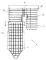
- FIG. 1 is a side view showing the overall configuration of the boiler device according to the present embodiment
- FIG. 2 is a plan view of the boiler device shown in FIG. 1
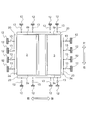
- FIG. 3 is a view showing the side surface of the boiler body and the arrangement of back stays shown in FIG. 4
- FIG. 4 is a perspective view of the back stay shown in FIG. 3
- FIG. 5 is a sectional view taken along line VV of FIG. 3
- FIG. 6 is a perspective view showing a main part of the reinforcing structure of the boiler furnace wall
- FIG. 7 is shown in FIG.
- FIG. 8 is a side view of the reinforcing structure shown in FIG. 6,
- FIG. 9 is a vertical cross-sectional view showing a main part of the reinforcing structure shown in FIG.
- the front-back, left-right, and up-down directions are defined as shown in FIGS. 1 and 2.
- the boiler device includes a boiler main body 1 and a plurality of steel frame columns 12 provided so as to surround the boiler main body 1 and support the boiler main body 1.
- the boiler main body 1 is suspended from a plurality of steel frame beams 11 spanning the upper portions of the plurality of steel frame columns 12 via a plurality of suspension rods 10.
- the boiler main body 1 includes a furnace 2, a cage portion 3, and a sub-side wall 4 connecting the furnace 2 and the cage portion 3.
- the furnace 2 is surrounded by a water wall 2a (see FIGS. 6 to 8) formed by welding and fixing water pipes (heat transfer tubes) 7 through which boiler water flows inside with a membrane bar 8. ..
- the cage portion 3 is also surrounded by a cage wall 3a having a configuration similar to that of the water wall 2a. 5 will be added.
- the furnace 2 and the cage portion 3 are connected to a plurality of steel frame columns 12 provided around the boiler furnace wall 5 via a plurality of psychic ties 13. More specifically, the back stay 20 provided so as to surround the water wall 2a and the steel frame column 12 are connected by a sysmic tie 13, and the back stay 20 provided so as to surround the cage wall 3a.
- the steel column 12 is connected by a cysmic tie 13.
- the backstay 20 is a member for reinforcing the boiler furnace wall 5 against the pressure of the combustion gas in the furnace 2 and the cage portion 3, and for example, H-shaped steel is used. That is, during the operation of the boiler main body 1, the water wall 2a of the furnace 2 receives the internal pressure generated by the internal combustion air and combustion gas. This pressure inside the furnace acts on the water wall 2a and the cage wall 3a in a positive and negative manner, and the water wall 2a and the cage wall 3a exhibit swelling and deformation behavior. Therefore, in order to prevent excessive deformation of the water wall 2a and the cage wall 3a, as shown in FIGS. 20 are arranged. For example, as shown in FIG. 5, deformation of the furnace 2 is prevented by surrounding the four sides of the furnace 2 with a back stay 20 extending in the horizontal direction.
- a tie bar 30 is connected to the back stay 20 and the tie bar 30 is connected. Is attached to the water wall 2a (boiler furnace wall 5) of the furnace 2.
- the reinforcing structure of the boiler furnace wall 5 using the back stay 20 and the tie bar 30 will be described with reference to FIGS. 6 to 9.
- the boiler furnace wall 5 is welded and joined in a panel shape by alternately arranging water pipes 7 and membrane bars 8 in order to flatten the outer surface of the boiler furnace wall 5.
- the filler plate 31 is welded and fixed to a predetermined range on the outer surface of the boiler furnace wall 5.
- a pair of anchor plates 32 are welded and fixed to the filler plate 31 at predetermined intervals in the vertical direction, and a tie bar 30 is arranged between the anchor plates 32.
- the anchor plates 32 do not necessarily have to be paired, and the anchor plates 32 may be provided on only one of the upper and lower surfaces.
- the anchor plate 32 is a long member having a long axis in the horizontal direction, and the entire circumference thereof is welded and fixed to the filler plate 31.
- the anchor plate 32 and the tie bar 30 are not welded, and a concave groove portion 32a is formed as an engaging portion with the tie bar 30 at the central portion along the longitudinal direction of the anchor plate 32.
- a slit 32b extending in the longitudinal direction is formed in most of the anchor plate 32 including the groove portion 32a, and the slit 32b alleviates the influence of thermal deformation due to the temperature difference with the boiler furnace wall 5. It has become.
- the tie bar 30 is a plate-shaped member horizontally arranged along the outer surface of the boiler furnace wall 5, and is supported on the outer surface of the boiler furnace wall 5 by a plurality of holding pins 33.
- the anchor plate 32 and the tie bar 30 are not welded, and the tie bar 30 is formed with a pair of protruding pieces 30a fitted in the groove portion 32a of the anchor plate 32 protruding in the vertical direction.
- the groove portion 32a and the protruding piece 30a are unevenly engaged with each other with a gap of about several millimeters, and after the protruding piece 30a is fitted into the groove portion 32a, they are arranged at four locations so as to straddle the joint portion between the two.
- the tie bar 30 By welding and fixing the stopper member 34 to the anchor plate 32, the tie bar 30 is prevented from falling off from the anchor plate 32.
- a standoff 35 is fixed to the outer surface of the tie bar 30, and the backstay 20 is in contact with the standoff 35 (see FIG. 8).
- the stopper member 34 may be welded and fixed to at least the anchor plate 32 of the anchor plate 32 and the protruding piece 30a.
- all the stopper members 34 may be welded and fixed to the anchor plate 32 and the protruding piece 30a. good.
- the upper two stopper members 34 are welded and fixed to the anchor plate 32, and the lower two stopper members 34 are projected pieces 30a. It may be fixed by welding.
- a protruding piece 30a is formed on the anchor portion set on the tie bar 30, and the protruding piece 30a and the groove portion 32a of the anchor plate 32 welded and fixed to the filler plate 31 of the boiler furnace wall 5 are formed.
- the difference in elongation between the boiler furnace wall 5 and the back stay 20 centered on the reference point of the tie bar 30 is absorbed.
- the thermal expansion and contraction of the anchor plate 32 welded and fixed to the boiler furnace wall 5 side is absorbed by the gap existing between the groove portion 32a of the anchor plate 32 and the protruding piece 30a of the tie bar 30, so that the anchor plate 32
- the temperature followability to the boiler furnace wall 5 is improved, and it is possible to suppress the occurrence of cracks in the welded portion of the anchor plate 32.
- the anchor plates 32 are arranged at two positions above and below the tie bar 30 and the entire circumference of these anchor plates 32 is welded and fixed to the filler plate 31 of the boiler furnace wall 5, even if the anchor plate 32 is miniaturized. The strength required for the anchor portion of the tie bar 30 can be secured.
- the boiler furnace wall 5 is supported by the steel frame column 12 via the back stay 20 connected to the tie bar 30, the horizontal vibration acting at the time of an earthquake is caused by the back stay 20 and the steel frame column 12. It is alleviated by the intervening sismic tie 13.
- the amount of displacement of the boiler body 1 at the time of an earthquake is larger than that at normal times, and the anchor plate 32 is displaced by an amount of movement far exceeding the gap between the groove portion 32a and the protruding piece 30a.
- the 32 and the tie bar 30 vibrate integrally.
- the boiler device includes a boiler main body 1 having a boiler furnace wall 5 composed of a water pipe 7, a steel pillar 12 provided around the boiler main body 1, and a boiler main body 1.
- a back stay 20 that surrounds and extends in the horizontal direction and a tie bar 30 that supports the back stay 20 on the boiler furnace wall 5 are provided, and the steel pillar 12 and the back stay 20 are connected via a psychic tie 13. Therefore, damage to the boiler main body 1 can be reduced when an earthquake occurs.
- the anchor portion set on the tie bar 30 was separated from the tie bar 30, the anchor plate 32 as the anchor portion was welded and fixed to the boiler furnace wall 5, and the protruding piece 30a formed on the tie bar 30 was formed on the anchor plate 32.
- the stopper member 34 prevents the protruding piece 30a from falling off from the groove portion 32a, it is not necessary to weld the tie bar 30 to the boiler furnace wall 5, and the tie bar 30 is not welded. Weld cracks generated at the fixed points of 30 can be suppressed.
- the anchor plates 32 are arranged at two positions above and below the tie bar 30 and the entire circumference of these anchor plates 32 is welded and fixed to the boiler furnace wall 5, the anchor plate 32 can be miniaturized and thermal stress is reduced. It can be reduced, and the strength required for the anchor portion of the tie bar 30 can be secured.
- the anchor portion (anchor plate 32) serving as the elongation reference point set on the tie bar 30 is separated from the tie bar 30, and the anchor plate 32 is attached to the boiler furnace wall 5.
- the protruding piece 30a formed on the tie bar 30 is engaged with the groove portion 32a formed on the anchor plate 32 with a gap so that the protruding piece 30a does not fall off from the groove portion 32a by the stopper member 34. Since it is configured, it is not necessary to weld the tie bar 30 to the boiler furnace wall 5, and welding cracks generated at the fixed portion of the tie bar 30 can be suppressed.
- the present invention is not limited to the above-described embodiment, and includes various modifications.
- the above-described embodiments have been described in detail in order to explain the present invention in an easy-to-understand manner, and are not necessarily limited to those having all the described configurations.
- Boiler body 1
- Water wall 3
- Cage part 3
- Sub-side wall 5
- Boiler furnace wall (furnace wall) 7
- Water pipe 8
- Membrane bar 10
- Suspension rod 11
- Steel beam 12
- Steel column 13
- Physmic tie 20
- Backstay 30
- Tie bar 30a Projection piece
- Filler plate 32
- Anchor plate 32a Groove 32b Slit 33 Hold pin 34 Stopper member 35 Standoff
Landscapes
- Engineering & Computer Science (AREA)
- Physics & Mathematics (AREA)
- Thermal Sciences (AREA)
- Mechanical Engineering (AREA)
- General Engineering & Computer Science (AREA)
- Conveying And Assembling Of Building Elements In Situ (AREA)
- Reinforcement Elements For Buildings (AREA)
Priority Applications (1)
| Application Number | Priority Date | Filing Date | Title |
|---|---|---|---|
| JP2022509271A JP7353463B2 (ja) | 2020-03-25 | 2020-12-21 | ボイラ装置およびボイラ炉壁の補強構造 |
Applications Claiming Priority (2)
| Application Number | Priority Date | Filing Date | Title |
|---|---|---|---|
| JP2020-054586 | 2020-03-25 | ||
| JP2020054586 | 2020-03-25 |
Publications (1)
| Publication Number | Publication Date |
|---|---|
| WO2021192461A1 true WO2021192461A1 (ja) | 2021-09-30 |
Family
ID=77891234
Family Applications (1)
| Application Number | Title | Priority Date | Filing Date |
|---|---|---|---|
| PCT/JP2020/047725 Ceased WO2021192461A1 (ja) | 2020-03-25 | 2020-12-21 | ボイラ装置およびボイラ炉壁の補強構造 |
Country Status (2)
| Country | Link |
|---|---|
| JP (1) | JP7353463B2 (https=) |
| WO (1) | WO2021192461A1 (https=) |
Citations (6)
| Publication number | Priority date | Publication date | Assignee | Title |
|---|---|---|---|---|
| JPS5238648A (en) * | 1975-09-22 | 1977-03-25 | Babcock Hitachi Kk | Supporting device for facing material of furnace wall |
| JPS53118601A (en) * | 1977-03-24 | 1978-10-17 | Babcock Hitachi Kk | Supporting device |
| JPS5771902U (https=) * | 1980-10-14 | 1982-05-01 | ||
| JPH01291002A (ja) * | 1988-05-16 | 1989-11-22 | Babcock Hitachi Kk | ボイラ周壁管支持構造体 |
| JPH06101804A (ja) * | 1992-04-03 | 1994-04-12 | Babcock & Wilcox Co:The | ボイラーに於ける板状溶接チューブ壁の端部を連結するための控えステーシステム |
| US5557901A (en) * | 1994-11-15 | 1996-09-24 | The Babcock & Wilcox Company | Boiler buckstay system |
Family Cites Families (2)
| Publication number | Priority date | Publication date | Assignee | Title |
|---|---|---|---|---|
| KR101613814B1 (ko) * | 2015-01-29 | 2016-04-19 | 문인득 | 2루프 가압경수로형 증기 발생기의 교체 방법 |
| KR20170133895A (ko) * | 2016-05-27 | 2017-12-06 | 문인득 | 가압경수로형 원자로 증기 발생기의 공기정체구역 공기 순환 냉각 장치 |
-
2020
- 2020-12-21 JP JP2022509271A patent/JP7353463B2/ja active Active
- 2020-12-21 WO PCT/JP2020/047725 patent/WO2021192461A1/ja not_active Ceased
Patent Citations (6)
| Publication number | Priority date | Publication date | Assignee | Title |
|---|---|---|---|---|
| JPS5238648A (en) * | 1975-09-22 | 1977-03-25 | Babcock Hitachi Kk | Supporting device for facing material of furnace wall |
| JPS53118601A (en) * | 1977-03-24 | 1978-10-17 | Babcock Hitachi Kk | Supporting device |
| JPS5771902U (https=) * | 1980-10-14 | 1982-05-01 | ||
| JPH01291002A (ja) * | 1988-05-16 | 1989-11-22 | Babcock Hitachi Kk | ボイラ周壁管支持構造体 |
| JPH06101804A (ja) * | 1992-04-03 | 1994-04-12 | Babcock & Wilcox Co:The | ボイラーに於ける板状溶接チューブ壁の端部を連結するための控えステーシステム |
| US5557901A (en) * | 1994-11-15 | 1996-09-24 | The Babcock & Wilcox Company | Boiler buckstay system |
Also Published As
| Publication number | Publication date |
|---|---|
| JPWO2021192461A1 (https=) | 2021-09-30 |
| JP7353463B2 (ja) | 2023-09-29 |
Similar Documents
| Publication | Publication Date | Title |
|---|---|---|
| JP6640459B2 (ja) | 免震化構造、鉄骨支持構造体及び既設鉄骨支持構造体の免震化工法 | |
| JP6071023B2 (ja) | ガラス成形装置用の溶解装置 | |
| KR20120049425A (ko) | 파이프 용접 변형 방지용 지그장치 | |
| US3814063A (en) | Support of tube walls | |
| JP2019116794A (ja) | 鉄骨梁接合構造 | |
| JP5042234B2 (ja) | 発電用ボイラの壁を支持するための方法及び装置 | |
| KR100808358B1 (ko) | 보일러 벅스테이 코너 연결장치 | |
| WO2021192461A1 (ja) | ボイラ装置およびボイラ炉壁の補強構造 | |
| KR101526141B1 (ko) | 벅스테이 시스템 | |
| JP5603741B2 (ja) | 座屈拘束ブレース | |
| TWI744815B (zh) | 鍋爐裝置 | |
| JP2011064288A (ja) | 配管拘束支持体 | |
| WO2019013150A1 (ja) | ボイラ炉壁の交換工法及びボイラ炉壁の仮保持構造 | |
| KR102012499B1 (ko) | 화력발전용 보일러 나선형 수냉벽의 하중 지지구조 | |
| JP2000291903A (ja) | ボイラ天井壁貫通部のシールプレート構造 | |
| WO2018230014A1 (ja) | 弾塑性エレメント及びそれを備えたサイスミックタイ、ならびにボイラの支持構造体 | |
| JP6606037B2 (ja) | 架構型配管拘束支持具、架構型配管拘束支持構造体、架構型配管拘束支持構造体の組立て方法 | |
| JP7558793B2 (ja) | 輸送枠構造および輸送方法 | |
| JP2020153221A (ja) | 四面溶接箱形断面柱の組立方法、スキンプレート部材、四面溶接箱形断面柱、およびコンクリート充填鋼管柱 | |
| KR101690513B1 (ko) | 보일러 벅스테이 코너 연결장치 | |
| JP7645084B2 (ja) | ボイラ装置及びボイラ装置のペントハウス支持方法 | |
| JP2019044327A (ja) | 継手構造 | |
| JP2022088891A (ja) | 弾塑性エレメント及びそれを備えたサイスミックタイ、ならびにボイラの支持構造体 | |
| JP2014005626A (ja) | 構造物防振用相対変位制限構造及び該構造物防振用相対変位制限構造を備えたボイラ | |
| JP2001304505A (ja) | ボイラ振れ止め構造 |
Legal Events
| Date | Code | Title | Description |
|---|---|---|---|
| 121 | Ep: the epo has been informed by wipo that ep was designated in this application |
Ref document number: 20927388 Country of ref document: EP Kind code of ref document: A1 |
|
| ENP | Entry into the national phase |
Ref document number: 2022509271 Country of ref document: JP Kind code of ref document: A |
|
| NENP | Non-entry into the national phase |
Ref country code: DE |
|
| 122 | Ep: pct application non-entry in european phase |
Ref document number: 20927388 Country of ref document: EP Kind code of ref document: A1 |