WO2021186573A1 - 通信制御方法、制御局、及び通信制御プログラム - Google Patents
通信制御方法、制御局、及び通信制御プログラム Download PDFInfo
- Publication number
- WO2021186573A1 WO2021186573A1 PCT/JP2020/011783 JP2020011783W WO2021186573A1 WO 2021186573 A1 WO2021186573 A1 WO 2021186573A1 JP 2020011783 W JP2020011783 W JP 2020011783W WO 2021186573 A1 WO2021186573 A1 WO 2021186573A1
- Authority
- WO
- WIPO (PCT)
- Prior art keywords
- base stations
- control
- ratio
- transmission power
- station
- Prior art date
- Legal status (The legal status is an assumption and is not a legal conclusion. Google has not performed a legal analysis and makes no representation as to the accuracy of the status listed.)
- Ceased
Links
Images


Classifications
-
- H—ELECTRICITY
- H04—ELECTRIC COMMUNICATION TECHNIQUE
- H04W—WIRELESS COMMUNICATION NETWORKS
- H04W52/00—Power management, e.g. Transmission Power Control [TPC] or power classes
- H04W52/04—Transmission power control [TPC]
- H04W52/18—TPC being performed according to specific parameters
- H04W52/24—TPC being performed according to specific parameters using SIR [Signal to Interference Ratio] or other wireless path parameters
-
- H—ELECTRICITY
- H04—ELECTRIC COMMUNICATION TECHNIQUE
- H04W—WIRELESS COMMUNICATION NETWORKS
- H04W16/00—Network planning, e.g. coverage or traffic planning tools; Network deployment, e.g. resource partitioning or cells structures
- H04W16/18—Network planning tools
-
- H—ELECTRICITY
- H04—ELECTRIC COMMUNICATION TECHNIQUE
- H04W—WIRELESS COMMUNICATION NETWORKS
- H04W52/00—Power management, e.g. Transmission Power Control [TPC] or power classes
- H04W52/04—Transmission power control [TPC]
- H04W52/06—TPC algorithms
-
- H—ELECTRICITY
- H04—ELECTRIC COMMUNICATION TECHNIQUE
- H04W—WIRELESS COMMUNICATION NETWORKS
- H04W52/00—Power management, e.g. Transmission Power Control [TPC] or power classes
- H04W52/04—Transmission power control [TPC]
- H04W52/06—TPC algorithms
- H04W52/14—Separate analysis of uplink or downlink
- H04W52/143—Downlink power control
-
- H—ELECTRICITY
- H04—ELECTRIC COMMUNICATION TECHNIQUE
- H04W—WIRELESS COMMUNICATION NETWORKS
- H04W52/00—Power management, e.g. Transmission Power Control [TPC] or power classes
- H04W52/04—Transmission power control [TPC]
- H04W52/30—Transmission power control [TPC] using constraints in the total amount of available transmission power
- H04W52/36—Transmission power control [TPC] using constraints in the total amount of available transmission power with a discrete range or set of values, e.g. step size, ramping or offsets
- H04W52/367—Power values between minimum and maximum limits, e.g. dynamic range
-
- H—ELECTRICITY
- H04—ELECTRIC COMMUNICATION TECHNIQUE
- H04W—WIRELESS COMMUNICATION NETWORKS
- H04W88/00—Devices specially adapted for wireless communication networks, e.g. terminals, base stations or access point devices
- H04W88/08—Access point devices
-
- Y—GENERAL TAGGING OF NEW TECHNOLOGICAL DEVELOPMENTS; GENERAL TAGGING OF CROSS-SECTIONAL TECHNOLOGIES SPANNING OVER SEVERAL SECTIONS OF THE IPC; TECHNICAL SUBJECTS COVERED BY FORMER USPC CROSS-REFERENCE ART COLLECTIONS [XRACs] AND DIGESTS
- Y02—TECHNOLOGIES OR APPLICATIONS FOR MITIGATION OR ADAPTATION AGAINST CLIMATE CHANGE
- Y02D—CLIMATE CHANGE MITIGATION TECHNOLOGIES IN INFORMATION AND COMMUNICATION TECHNOLOGIES [ICT], I.E. INFORMATION AND COMMUNICATION TECHNOLOGIES AIMING AT THE REDUCTION OF THEIR OWN ENERGY USE
- Y02D30/00—Reducing energy consumption in communication networks
- Y02D30/70—Reducing energy consumption in communication networks in wireless communication networks
Definitions
- the present invention relates to a communication control method, a control station, and a communication control program.
- OFDM Orthogonal Frequency Division Multiplexing
- MIMO Multiple Input Multiple Output
- a maximum transmission speed of 600 Mbit / s is realized by using a channel bonding technology that utilizes a frequency channel of 40 MHz by simultaneously using two of the above.
- channel bonding technology that simultaneously uses up to eight 20 MHz frequency channels in the 5 GHz band and uses them as a maximum 160 MHz frequency channel, or multiple destinations on the same wireless channel.
- multi-user MIMO technology or the like that simultaneously transmits different signals, wireless communication that is faster and more efficient than the IEEE802.11n standard is realized (see, for example, Non-Patent Document 1).
- a base station if the transmission power of a base station is low, radio waves do not reach sufficiently within a predetermined area (cover area), and conversely, if the transmission power of a base station is high, radio wave interference between cells occurs. , The transmission power of the base station may be controlled to form an appropriate coverage area.
- a transmission power control method for controlling the transmission power of a base station has been considered so that a terminal station can obtain a predetermined received power in the entire cover area formed by a wireless communication system.
- IEEE Std 802.11-2016 IEEE Standard for Information technology-Telecommunications and information exchange between systems Local and metropolitan area networks-Specific requirements Part 11: Wireless LAN Medium Access Control (MAC) and Physical Layer (PHY) Specifications, IEEE Std 802.11-2016
- the arrangement of base stations is uneven with respect to the entire cover area, or if the environments around the base stations are different, control is performed so that the terminal station can obtain a predetermined received power in the entire cover area. Then, the size of the cell (accommodation range: individual cover area) may differ for each base station.
- the terminal station when there are a plurality of base stations that can be detected by the terminal station, the terminal station generally tries to connect to the base station having the highest received power. At this time, the connection of the terminal station is concentrated on some base stations, which may cause congestion in the wireless communication system.
- An object of the present invention is to provide a communication control method, a control station, and a communication control program capable of preventing the connection of terminal stations from being concentrated on some base stations in a wireless communication system. ..
- the communication control method maximizes the transmission power of each of the base stations in the communication control method of controlling the transmission power transmitted by each of the base stations in a coverage area covered by a plurality of base stations.
- the ratio of the individual cover area to the cover area which is the range in which each of the base stations individually accommodates the terminal station, is set to the base.
- the ratio calculation process calculated for each station and the maximum value of the calculated ratio deviate from the average value by a predetermined value or more, the transmission power of any of the base stations having the maximum ratio is reduced.
- control step Including a control step of controlling the ratio of the individual cover area to the cover area so as to be newly calculated for each base station, in the control step, the maximum value of the calculated ratio is less than a predetermined value from the average value. It is characterized by continuing control until there is a divergence.
- control station maximizes the transmission power of each of the base stations in the control station that controls the transmission power transmitted by each of the base stations in the cover area covered by the plurality of base stations.
- the ratio of the individual cover area to the cover area which is the range in which each of the base stations individually accommodates the terminal station, is the base.
- One of the base stations in which the ratio is the maximum value when the ratio calculation unit calculated for each station and the maximum value of the ratio calculated by the ratio calculation unit deviate from the average value by a predetermined value or more.
- the control unit has a control unit that reduces the transmission power and controls the ratio of the individual cover area to the cover area so that the ratio calculation unit newly calculates the ratio for each base station, and the control unit calculates the ratio.
- the feature is that the control is continued until the maximum value of the ratio calculated by the unit deviates from the average value by less than a predetermined value.
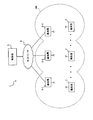
- FIG. 1 is a diagram showing a configuration example of a wireless communication system 1 according to an embodiment.
- the wireless communication system 1 includes, for example, three base stations 3-1 to 3-3 to which a plurality of terminal stations 2 can be connected by wireless communication, and a control station 5 connected to the network 4. And have.
- base station 3 When any one of a plurality of configurations such as base stations 3-1 to 3-3 is not specified, it is simply abbreviated as base station 3 or the like.
- the terminal station 2 receives a signal such as a beacon transmitted by the base station 3, and transmits information such as the signal strength (received power) of the received signal, the receiving position, and the MAC address of the own station to the base station 3.
- a signal such as a beacon transmitted by the base station 3
- information such as the signal strength (received power) of the received signal, the receiving position, and the MAC address of the own station to the base station 3.
- Base stations 3-1 to 3-3 are installed so that their cells (accommodation range: individual coverage area) overlap with the cells of other base stations 3, and are connected to the network 4.
- the individual cover area is any one of the base stations 3-1 to 3-3 having the maximum received power received by the terminal station 2 at that point (reception position of the terminal station 2).
- the terminal station 2 located at the point is accommodated (covered)
- the range covered by each of the base stations 3 is shown.
- the individual coverage area is not limited to the above definition, and is, for example, an area in which the base station 3 that transmits a signal whose received power received by the terminal station 2 is equal to or higher than a predetermined value accommodates the terminal station 2. May be.
- the set of cells of the base stations 3-1 to 3-3, that is, the area where the base stations 3-1 to 3-3 enable wireless communication is the cover area 100.
- cover area 100 may be set by excluding an area where the terminal station 2 does not exist, or a weight may be set in an area where many terminal stations 2 exist.
- the base stations 3-1 to 3-3 are made capable of receiving the received power (signal strength) transmitted by the terminal station 2 and the acquired reception position and MAC address from each of the terminal stations 2.
- FIG. 2 is a functional block diagram illustrating the functions of the control station 5 according to the embodiment.
- the control station 5 includes, for example, a communication unit 50, a collection unit 51, a ratio calculation unit 52, a storage unit 53, a setting unit 54, and a control unit 55. Then, the control station 5 controls the transmission power transmitted by each of the base stations 3 to one cover area 100 (see FIG. 1) that enables the base stations 3-1 to 3-3 to perform wireless communication.
- the communication unit 50 is a communication interface that communicates with each of the base stations 3-1 to 3-3 via the network 4.
- the collection unit 51 collects the signal strength, reception position, MAC address, etc. received from the terminal station 2 by the base stations 3-1 to 3-3 via the communication unit 50, and outputs the signal strength to the ratio calculation unit 52. ..
- the ratio calculation unit 52 is an individual cover area in which each of the base stations 3-1 to 3-3 individually accommodates the terminal station 2 based on the signal strength, reception position, MAC address, etc. collected by the collection unit 51.
- the ratio of 10-1 to 10-3 (see FIG. 4) to the cover area 100 (individual cover area ratio) is calculated for each base station 3, and the calculation result is output to the storage unit 53 and the control unit 55.
- the storage unit 53 stores the result calculated by the ratio calculation unit 52, the communication control program included in the control station 5, and the like.
- the setting unit 54 makes settings via the communication unit 50 so as to maximize the transmission power of each of the base stations 3-1 to 3-3 as an initial value, for example. Further, the setting unit 54 sets the transmission power of each of the base stations 3-1 to 3-3 according to the control of the control unit 55.
- the control unit 55 controls each unit constituting the control station 5. For example, in the control unit 55, when the maximum value of the ratio calculated by the ratio calculation unit 52 deviates from the average value by a predetermined value or more, the control unit 55 has the maximum value of the base stations 3-1 to 3-3. One of the transmission powers is lowered, and the ratio of the individual cover area to the cover area is controlled so that the ratio calculation unit 52 newly calculates the ratio for each base station 3.
- control unit 55 continues the control until the maximum value of the ratio calculated by the ratio calculation unit 52 deviates from the average value by less than a predetermined value. Further, the control unit 55 is within a range in which all of the terminal stations 2 located in the cover area 100 enable wireless communication with at least one of the base stations 3-1 to 3-3, and the base stations 3-1 to 3 Control to reduce the transmission power of any of -3. The control unit 55 may control the predetermined base station 3 so as to increase the transmission power.
- FIG. 3 is a flowchart showing a specific example of communication control performed by the control station 5.
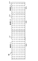
- FIG. 4 is a diagram schematically showing the relationship between the individual cover areas 10-1 to 10-3 of each of the base stations 3-1 to 3-3 and the cover area 100 of the wireless communication system 1.
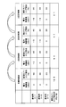
- FIG. 5 is a diagram schematically showing a process in which the control station 5 performs communication control.
- step 100 the setting unit 54 sets to maximize the transmission power of each of the base stations 3-1 to 3-3 via the communication unit 50 and the network 4.
- step 102 the ratio calculation unit 52 determines the ratio of the individual cover areas 10-1 to 10-3 to the cover area 100 based on, for example, the signal strength, reception position, and MAC address collected by the collection unit 51. Individual coverage area ratio) is calculated for each base station 3.
- the ratio calculation unit 52 measures the initial value of the individual cover area 10-1 of the base station 3-1 and the individual cover area 10-2 of the base station 3-2, and the base station 3 as an initial value measurement.
- the ratio of the individual cover area 10-3 to the cover area 100 of -3 is calculated for each base station 3.
- the power control value from the control station 5 for each of the base stations 3-1 to 3-3 is 0 dBm.
- the individual coverage area ratio of base station 3-1 is 50%
- the individual coverage area ratio of base station 3-2 is 30%
- the individual coverage area ratio of base station 3-3 is 20%.
- each of the circles ( ⁇ ) marks shown in FIG. 4 is uniform in that the terminal station 2 receives the signal transmitted by each of the base stations 3-1 to 3-3 within the individual coverage areas 10-1 to 10-3.
- the reception position (measurement point of signal strength) set in is schematically shown.
- step 104 the control unit 55 determines whether or not the maximum value of the individual coverage area ratio deviates from the average value by a predetermined value or more.
- the control unit 55 determines that the maximum value of the individual coverage area ratio deviates from the average value by a predetermined value or more (S104: Yes)
- the process proceeds to S106 and determines that the value does not deviate by the predetermined value or more.
- S104: No the process ends.
- control unit 55 determines whether or not the maximum value of the individual coverage area ratio deviates from the average value by a predetermined value or more based on, for example, the variation (standard deviation) of the individual coverage area ratio.
- the variation of the individual coverage area ratio is 12.5.
- step 106 the control unit 55 selects the base station 3 whose transmission power deviates most from the average value.
- step 108 the control unit 55 determines whether or not the deviation from the average value of the transmission power of the base station 3 selected in the process of S106 is less than a predetermined value.
- the control unit 55 proceeds to the process of S112 when the deviation from the average value is less than the predetermined value (S108: Yes), and when the deviation from the average value is not less than the predetermined value (S108: No), the control unit 55 proceeds to the process of S110. Proceed to processing.
- step 110 the setting unit 54 sets the power control value of the base station 3 to be lowered by a predetermined step according to the control of the control unit 55, and returns to the process of S102.
- the setting unit 54 sets the power control value to ⁇ for the base station 3-1 in which the maximum value of the individual coverage area ratio deviates from the average value by a predetermined value or more, as in the first control shown in FIG. Power control to 3 dBm is performed.
- the power control in which the power control value is -3 dBm is one step of the power control, but the magnitude of the power control value in one step is variable.
- the individual coverage area ratio of the base station 3-1 is 40%
- the individual coverage area ratio of the base station 3-2 is 40%
- the individual coverage area ratio of the base station 3-3 is 20% (see S102). ..
- the variation in the individual coverage area ratio is 9.4.
- step 112 the setting unit 54 sets the power control value of the base station 3 to be increased by a predetermined step according to the control of the control unit 55, and returns to the process of S102.
- control station 5 continues the process until it is determined that the maximum value of the individual coverage area ratio does not deviate from the average value by a predetermined value or more.
- the setting unit 54 sets the power control value to-for the base station 3-2 in which the maximum value of the individual coverage area ratio deviates from the average value by a predetermined value or more, as in the second control shown in FIG. Power control to 3 dBm is performed.
- the individual coverage area ratio of base station 3-1 is 40%
- the individual coverage area ratio of base station 3-2 is 30%
- the individual coverage area ratio of base station 3-3 is 30%.
- the variation in the individual coverage area ratio is 4.7.
- the setting unit 54 sets the individual cover area as in the third control shown in FIG. Power control is performed with the power control value set to -6 dBm for the base station 3-1 in which the maximum value of the ratio deviates from the average value by a predetermined value or more.
- the individual coverage area ratio of base station 3-1 is 35%
- the individual coverage area ratio of base station 3-2 is 33%
- the individual coverage area ratio of base station 3-3 is 30%.
- the variation in the individual coverage area ratio is 2.1.
- the control station 5 determines that the maximum value of the individual coverage area ratio does not deviate from the average value by a predetermined value or more. In this case, the control station 5 ends the communication control process after performing the third control shown in FIG.
- the wireless communication system 1 can evenly approach the individual coverage areas of the base stations 3-1 to 3-3, and the terminal station 2 can be compared with some base stations 3 in the wireless communication system 1. It is possible to prevent the connections from being concentrated.
- the wireless communication system 1 performs the above-described processing with the area where the base stations 3-1 to 3-3 enable wireless communication as the cover area 100, the base stations 3-1 to 3-3 are within the cover area 100. It is possible to control the transmission power of each of the base stations 3-1 to 3-3 so as not to generate a "dead zone" in which a signal cannot be received from any of the three.
- the wireless communication system 1 may be configured to set a control range (upper limit and lower limit) of transmission power for each base station 3 and secure the minimum power required for each base station 3.
- each function of the terminal station 2, the base station 3, and the control station 5 may be partially or wholly configured by hardware such as PLD (Programmable Logic Device) or FPGA (Field Programmable Gate Array). However, it may be configured as a program executed by a processor such as a CPU.
- PLD Processable Logic Device
- FPGA Field Programmable Gate Array
- control station 5 can be realized by using a computer and a program, and the program can be recorded on a storage medium or provided through a network.
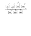
- FIG. 6 is a diagram showing a hardware configuration example of the control station 5 according to the embodiment.
- the control station 5 has an input unit 500, an output unit 510, a communication unit 520, a CPU 530, a memory 540, and an HDD 550 connected via a bus 560, and has a function as a computer. Further, the control station 5 is configured to be able to input / output data to / from a computer-readable storage medium 570.
- the input unit 500 is, for example, a keyboard, a mouse, or the like.
- the output unit 510 is a display device such as a display.
- the communication unit 520 is, for example, a wired network interface.
- the CPU 530 controls each unit constituting the control station 5 and performs predetermined processing and the like.
- the memory 540 and the HDD 550 form a storage unit for storing data and the like.
- the memory 540 stores each data used in the above-mentioned processing.
- the storage medium 570 is capable of storing a communication control program or the like that executes a function of the control station 5.
- the architecture constituting the control station 5 is not limited to the example shown in FIG.
- the "computer” here includes hardware such as an OS and peripheral devices.
- the "computer-readable storage medium” refers to a storage device such as a flexible disk, a magneto-optical disk, a ROM, a portable medium such as a CD-ROM, or the like.
- a "computer-readable storage medium” is a communication line for transmitting a program via a network such as the Internet or a communication line such as a telephone line, and dynamically holds the program for a short period of time. It may include a program or a program that holds a program for a certain period of time, such as a volatile memory inside a computer that is a server or a client in that case.
Landscapes
- Engineering & Computer Science (AREA)
- Computer Networks & Wireless Communication (AREA)
- Signal Processing (AREA)
- Mobile Radio Communication Systems (AREA)
Abstract
複数の基地局によりカバーされるカバーエリアで基地局それぞれが送信する送信電力を制御する通信制御方法において、基地局それぞれの送信電力を最大にするように設定し、基地局それぞれが送信電力を最大にした場合に、基地局それぞれが個別に端末局を収容する範囲となる個別カバーエリアのカバーエリアに対する割合を基地局ごとに算出し、算出した割合の最大値が平均値から所定値以上乖離している場合に、割合が最大値となっている基地局のいずれかの送信電力を下げさせ、個別カバーエリアのカバーエリアに対する割合を基地局ごとに新たに算出し、算出した割合の最大値が平均値から所定値未満の乖離となるまで制御を継続する。
Description
本発明は、通信制御方法、制御局、及び通信制御プログラムに関する。
例えば、2.4GHz帯又は5GHz帯の電波を用いた無線通信システムとして、IEEE802.11a規格、及びIEEE802.11g規格などに基づくものがある。ここで、直交周波数分割多重(OFDM:Orthogonal Frequency Division Multiplexing)変調方式を用いることにより、マルチパスフェージング環境での特性を安定化させて、最大54Mbit/sの伝送速度を実現することが可能である。
また、IEEE802.11n規格に基づく無線通信システムでは、2.4GHz帯又は5GHz帯において、複数アンテナを用いて同一の無線チャネルで空間分割多重を行うMIMO(Multiple Input Multiple Output)や、20MHzの周波数チャネルを2つ同時に利用して40MHzの周波数チャネルを利用するチャネルボンディング技術を用いて、最大600Mbit/sの伝送速度を実現している。
また、IEEE802.11ac規格に基づく無線通信システムでは、5GHz帯において、20MHzの周波数チャネルを8つまで同時に利用し、最大160MHzの周波数チャネルとして利用するチャネルボンディング技術や、同一の無線チャネルで複数の宛先に対して異なる信号を同時伝送するマルチユーザMIMO技術等を利用し、IEEE802.11n規格より高速かつ高効率な無線通信を実現している(例えば、非特許文献1参照)。
また、無線通信システムにおいて、基地局の送信電力が低ければ電波が所定の領域(カバーエリア)内で十分に届かず、逆に基地局の送信電力が高ければセル間の電波干渉を生じさせるため、適切なカバーエリアを形成するために基地局の送信電力制御を行うことがある。
例えば、従来は、無線通信システムが形成するカバーエリア全体において端末局が所定の受信電力を得ることができるように、基地局の送信電力を制御する送信電力制御法が考えられていた。
IEEE Standard for Information technology- Telecommunications and information exchange between systems Local and metropolitan area networks- Specific requirements Part 11: Wireless LAN Medium Access Control (MAC) and Physical Layer (PHY) Specifications, IEEE Std 802.11-2016, Dec. 2016.
しかしながら、従来の送信電力制御法では、基地局がカバーエリア全体に対して均一に配置され、かつ基地局周辺の遮蔽や電波伝搬環境などが同一である場合には特に問題が生じないが、実環境では送信電力制御が仕様に対して不十分になることがある。
例えば、カバーエリア全体に対して基地局の配置が不均一であったり、基地局周辺の環境がそれぞれ異なる場合には、カバーエリア全体において端末局が所定の受信電力を得ることができるように制御すると、基地局ごとにセル(収容範囲:個別カバーエリア)の大きさが異なってくることがある。
また、端末局は、自局が検出できる基地局が複数存在する場合、一般的に最も受信電力が高い基地局への接続を試みる。このとき、一部の基地局に端末局の接続が集中してしまい、無線通信システムにおける混雑が発生してしまうことがある。
本発明は、無線通信システム内の一部の基地局に対して端末局の接続が集中することを防止することができる通信制御方法、制御局、及び通信制御プログラムを提供することを目的とする。
本発明の一態様にかかる通信制御方法は、複数の基地局によりカバーされるカバーエリアで前記基地局それぞれが送信する送信電力を制御する通信制御方法において、前記基地局それぞれの送信電力を最大にするように設定する設定工程と、前記基地局それぞれが送信電力を最大にした場合に、前記基地局それぞれが個別に端末局を収容する範囲となる個別カバーエリアの前記カバーエリアに対する割合を前記基地局ごとに算出する割合算出工程と、算出した割合の最大値が平均値から所定値以上乖離している場合に、割合が最大値となっている前記基地局のいずれかの送信電力を下げさせ、前記個別カバーエリアの前記カバーエリアに対する割合を前記基地局ごとに新たに算出するように制御する制御工程とを含み、前記制御工程では、算出した割合の最大値が平均値から所定値未満の乖離となるまで制御を継続することを特徴とする。
また、本発明の一態様にかかる制御局は、複数の基地局によりカバーされるカバーエリアで前記基地局それぞれが送信する送信電力を制御する制御局において、前記基地局それぞれの送信電力を最大にするように設定する設定部と、前記基地局それぞれが送信電力を最大にした場合に、前記基地局それぞれが個別に端末局を収容する範囲となる個別カバーエリアの前記カバーエリアに対する割合を前記基地局ごとに算出する割合算出部と、前記割合算出部が算出した割合の最大値が平均値から所定値以上乖離している場合に、割合が最大値となっている前記基地局のいずれかの送信電力を下げさせ、前記個別カバーエリアの前記カバーエリアに対する割合を前記基地局ごとに新たに前記割合算出部が算出するように制御する制御部とを有し、前記制御部は、前記割合算出部が算出した割合の最大値が平均値から所定値未満の乖離となるまで制御を継続することを特徴とする。
本発明によれば、無線通信システム内の一部の基地局に対して端末局の接続が集中することを防止することができる。
以下に、図面を用いて無線通信システムの一実施形態を説明する。図1は、一実施形態にかかる無線通信システム1の構成例を示す図である。図1に示すように、無線通信システム1は、例えば、複数の端末局2が無線通信によって接続可能な3台の基地局3-1~3-3と、ネットワーク4に接続された制御局5とを有する。なお、基地局3-1~3-3のように複数ある構成のいずれかを特定しない場合には、単に基地局3などと略記する。
端末局2は、基地局3が送信するビーコンなどの信号を受信し、受信信号の信号強度(受信電力)、受信位置及び自局のMACアドレスなどの情報を基地局3に対して送信する。
基地局3-1~3-3は、それぞれセル(収容範囲:個別カバーエリア)が他の基地局3のセルと重なるように設置されており、ネットワーク4に接続されている。
ここで、個別カバーエリアとは、その地点(端末局2の受信位置)において、端末局2が受信する受信電力が最大となっている基地局3-1~3-3のいずれかが、その地点に位置する端末局2を収容(カバー)していると定義したときに、基地局3それぞれが個別にカバーする範囲を示すこととする。
なお、個別カバーエリアは、上述した定義に限定されることなく、例えば端末局2が受信する受信電力が所定値以上となる信号を送信する基地局3が当該端末局2を収容する領域であるとされてもよい。
このとき、基地局3-1~3-3の少なくともいずれかは、所定の領域(カバーエリア)100内に位置する端末局2との間で無線通信を可能にされている。ここでは、基地局3-1~3-3それぞれのセルの集合、すなわち基地局3-1~3-3が無線通信を可能にする領域がカバーエリア100となっている。
なお、カバーエリア100は、端末局2が存在しない領域を除外して設定されてもよいし、端末局2が多く存在する領域に重み付けを設定されてもよい。
さらに、基地局3-1~3-3は、端末局2が送信した受信電力(信号強度)と、取得した受信位置及びMACアドレスを端末局2それぞれから受信可能にされている。
図2は、一実施形態にかかる制御局5が有する機能を例示する機能ブロック図である。図2に示すように、制御局5は、例えば、通信部50、収集部51、割合算出部52、記憶部53、設定部54、及び制御部55を有する。そして、制御局5は、基地局3-1~3-3が無線通信を可能にする1つのカバーエリア100(図1参照)に対して、基地局3それぞれが送信する送信電力を制御する。
具体的には、通信部50は、ネットワーク4を介して基地局3-1~3-3それぞれとの間で通信を行う通信インターフェースである。
収集部51は、通信部50を介して、基地局3-1~3-3が端末局2から受信する信号強度、受信位置及びMACアドレスなどを収集し、割合算出部52に対して出力する。
割合算出部52は、収集部51が収集した信号強度、受信位置及びMACアドレスなどに基づいて、基地局3-1~3-3それぞれが個別に端末局2を収容する範囲となる個別カバーエリア10-1~10-3(図4参照)のカバーエリア100に対する割合(個別カバーエリア割合)を基地局3ごとに算出し、算出結果を記憶部53及び制御部55に対して出力する。
記憶部53は、割合算出部52が算出した結果、及び制御局5が備える通信制御プログラムなどを記憶する。
設定部54は、例えば初期値として基地局3-1~3-3それぞれの送信電力を最大にするように、通信部50を介して設定を行う。また、設定部54は、制御部55の制御に応じて、基地局3-1~3-3それぞれの送信電力を設定する。
制御部55は、制御局5を構成する各部を制御する。例えば、制御部55は、割合算出部52が算出した割合の最大値が平均値から所定値以上乖離している場合に、割合が最大値となっている基地局3-1~3-3のいずれかの送信電力を下げさせ、個別カバーエリアのカバーエリアに対する割合を基地局3ごとに新たに割合算出部52が算出するように制御する。
また、制御部55は、割合算出部52が算出した割合の最大値が平均値から所定値未満の乖離となるまで制御を継続する。また、制御部55は、カバーエリア100内に位置する端末局2の全てが基地局3-1~3-3の少なくともいずれかと無線通信を可能にする範囲内で、基地局3-1~3-3のいずれかの送信電力を下げさせるように制御する。制御部55は、所定の基地局3に対し、送信電力を上げるように制御を行ってもよい。
次に、制御局5が行う通信制御の具体例について、図3~図5を用いて説明する。図3は、制御局5が行う通信制御の具体例を示すフローチャートである。図4は、基地局3-1~3-3それぞれの個別カバーエリア10-1~10-3と、無線通信システム1のカバーエリア100との関係を模式的に示す図である。図5は、制御局5が通信制御を行う過程を模式的に示す図である。
ステップ100(S100)において、設定部54は、通信部50及びネットワーク4を介して、基地局3-1~3-3それぞれの送信電力を最大にする設定を行う。
ステップ102(S102)において、割合算出部52は、例えば収集部51が収集した信号強度、受信位置及びMACアドレスなどに基づいて、個別カバーエリア10-1~10-3のカバーエリア100に対する割合(個別カバーエリア割合)を基地局3ごとに算出する。
例えば、図4に示すように、割合算出部52は、初期値測定として、基地局3-1の個別カバーエリア10-1、基地局3-2の個別カバーエリア10-2、及び基地局3-3の個別カバーエリア10-3のカバーエリア100に対する割合を基地局3ごとに算出する。
このとき、図4及び図5にも示すように、基地局3-1~3-3それぞれに対する制御局5からの電力制御値は0dBmである。また、基地局3-1の個別カバーエリア割合は50%、基地局3-2の個別カバーエリア割合は30%、基地局3-3の個別カバーエリア割合は20%となっている。
なお、図4に示した丸(〇)印それぞれは、個別カバーエリア10-1~10-3内で基地局3-1~3-3それぞれが送信する信号を端末局2が受信する一様に設定された受信位置(信号強度の測定点)を模式的に示している。
ステップ104(S104)において、制御部55は、個別カバーエリア割合の最大値が平均値から所定値以上乖離しているか否かを判定する。制御部55は、個別カバーエリア割合の最大値が平均値から所定値以上乖離していると判定した場合(S104:Yes)にはS106の処理に進み、所定値以上乖離していないと判定した場合(S104:No)には処理を終了する。
このとき、制御部55は、例えば個別カバーエリア割合のばらつき(標準偏差)に基づいて、個別カバーエリア割合の最大値が平均値から所定値以上乖離しているか否かを判定する。初期値測定時には、個別カバーエリア割合のばらつきは、12.5となっている。
ステップ106(S106)において、制御部55は、送信電力が平均値から最も乖離している基地局3を選択する。
ステップ108(S108)において、制御部55は、S106の処理で選択した基地局3の送信電力に関し、平均値からの乖離が所定値未満であるか否かを判定する。制御部55は、平均値からの乖離が所定値未満である場合(S108:Yes)にはS112の処理に進み、平均値からの乖離が所定値未満でない場合(S108:No)にはS110の処理に進む。
ステップ110(S110)において、設定部54は、制御部55の制御に応じて、当該基地局3の電力制御値を所定ステップだけ下げる設定を行い、S102の処理に戻る。例えば、設定部54は、図5に示した1回目制御のように、個別カバーエリア割合の最大値が平均値から所定値以上乖離している基地局3-1に対し、電力制御値を-3dBmとする電力制御を行う。ここでは、電力制御値を-3dBmとする電力制御を、電力制御の1ステップとするが、1ステップの電力制御値の大きさは可変であるとする。
このとき、基地局3-1の個別カバーエリア割合は40%、基地局3-2の個別カバーエリア割合は40%、基地局3-3の個別カバーエリア割合は20%となる(S102参照)。また、個別カバーエリア割合のばらつきは、9.4となる。
ステップ112(S112)において、設定部54は、制御部55の制御に応じて、当該基地局3の電力制御値を所定ステップだけ上げる設定を行い、S102の処理に戻る。
このように、制御局5は、個別カバーエリア割合の最大値が平均値から所定値以上乖離していないと判定するまで処理を継続する。
例えば、設定部54は、図5に示した2回目制御のように、個別カバーエリア割合の最大値が平均値から所定値以上乖離している基地局3-2に対し、電力制御値を-3dBmとする電力制御を行う。
このとき、基地局3-1の個別カバーエリア割合は40%、基地局3-2の個別カバーエリア割合は30%、基地局3-3の個別カバーエリア割合は30%となる。また、個別カバーエリア割合のばらつきは、4.7となる。
さらに、制御局5は、個別カバーエリア割合の最大値が平均値から所定値以上乖離していると判定した場合、設定部54は、図5に示した3回目制御のように、個別カバーエリア割合の最大値が平均値から所定値以上乖離している基地局3-1に対し、電力制御値を-6dBmとする電力制御を行う。
このとき、基地局3-1の個別カバーエリア割合は35%、基地局3-2の個別カバーエリア割合は33%、基地局3-3の個別カバーエリア割合は30%となる。また、個別カバーエリア割合のばらつきは、2.1となる。
例えば、制御局5は、個別カバーエリア割合のばらつきが3未満である場合に、個別カバーエリア割合の最大値が平均値から所定値以上乖離していないと判定する。この場合、制御局5は、図5に示した3回目制御を行った後に、通信制御の処理を終了する。
このように、無線通信システム1は、基地局3-1~3-3それぞれの個別カバーエリアを均等に近づけることができ、無線通信システム1内の一部の基地局3に対して端末局2の接続が集中することを防止することができる。
また、無線通信システム1は、基地局3-1~3-3が無線通信を可能にする領域をカバーエリア100として上述した処理を行うので、カバーエリア100内で基地局3-1~3-3のいずれからも信号を受信することができない「不感地帯」を発生させないように、基地局3-1~3-3それぞれの送信電力を制御することができる。
また、無線通信システム1は、基地局3ごとに送信電力の制御範囲(上限及び下限)を設定し、基地局3それぞれに必要な最低電力を確保するように構成されてもよい。
なお、端末局2、基地局3、及び制御局5が有する各機能は、それぞれ一部又は全部がPLD(Programmable Logic Device)やFPGA(Field Programmable Gate Array)等のハードウェアによって構成されてもよいし、CPU等のプロセッサが実行するプログラムとして構成されてもよい。
例えば、本発明にかかる制御局5は、コンピュータとプログラムを用いて実現することができ、プログラムを記憶媒体に記録することも、ネットワークを通して提供することも可能である。
図6は、一実施形態にかかる制御局5のハードウェア構成例を示す図である。図6に示すように、例えば制御局5は、入力部500、出力部510、通信部520、CPU530、メモリ540及びHDD550がバス560を介して接続され、コンピュータとしての機能を備える。また、制御局5は、コンピュータ読み取り可能な記憶媒体570との間でデータを入出力することができるようにされている。
入力部500は、例えばキーボード及びマウス等である。出力部510は、例えばディスプレイなどの表示装置である。通信部520は、例えば有線のネットワークインターフェースである。
CPU530は、制御局5を構成する各部を制御し、所定の処理等を行う。メモリ540及びHDD550は、データ等を記憶する記憶部を構成する。特に、メモリ540は、上述した処理に用いる各データを記憶する。記憶媒体570は、制御局5が有する機能を実行させる通信制御プログラム等を記憶可能にされている。なお、制御局5を構成するアーキテクチャは図6に示した例に限定されない。
すなわち、ここでいう「コンピュータ」とは、OSや周辺機器等のハードウェアを含むものとする。また、「コンピュータ読み取り可能な記憶媒体」とは、フレキシブルディスク、光磁気ディスク、ROM、CD-ROM等の可搬媒体等の記憶装置のことをいう。
さらに「コンピュータ読み取り可能な記憶媒体」とは、インターネット等のネットワークや電話回線等の通信回線を介してプログラムを送信する場合の通信線のように、短時間の間、動的にプログラムを保持するものや、その場合のサーバやクライアントとなるコンピュータ内部の揮発性メモリのように、一定時間プログラムを保持しているものを含んでもよい。
以上、図面を参照して本発明の実施形態を説明してきたが、上述の実施形態は、本発明の例示に過ぎず、本発明が上述の実施形態に限定されるものではないことは明らかである。したがって、本発明の技術思想及び範囲を逸脱しない範囲で、構成要素の追加、省略、置換、その他の変更が行われてもよい。
1・・・無線通信システム、2・・・端末局、3-1~3-3・・・基地局、4・・・ネットワーク、5・・・制御局、10-1~10-3・・・個別カバーエリア、50・・・通信部、51・・・収集部、52・・・割合算出部、53・・・記憶部、54・・・設定部、55・・・制御部、100・・・カバーエリア、500・・・入力部、510・・・出力部、520・・・通信部、530・・・CPU、540・・・メモリ、550・・・HDD、560・・・バス、570・・・記憶媒体
Claims (5)
- 複数の基地局によりカバーされるカバーエリアで前記基地局それぞれが送信する送信電力を制御する通信制御方法において、
前記基地局それぞれの送信電力を最大にするように設定する設定工程と、
前記基地局それぞれが送信電力を最大にした場合に、前記基地局それぞれが個別に端末局を収容する範囲となる個別カバーエリアの前記カバーエリアに対する割合を前記基地局ごとに算出する割合算出工程と、
算出した割合の最大値が平均値から所定値以上乖離している場合に、割合が最大値となっている前記基地局のいずれかの送信電力を下げさせ、前記個別カバーエリアの前記カバーエリアに対する割合を前記基地局ごとに新たに算出するように制御する制御工程と
を含み、
前記制御工程では、
算出した割合の最大値が平均値から所定値未満の乖離となるまで制御を継続すること
を特徴とする通信制御方法。 - 前記制御工程では、
前記カバーエリア内に位置する端末局の全てが複数の前記基地局の少なくともいずれかと無線通信を可能にする範囲内で、前記基地局のいずれかの送信電力を下げさせるように制御すること
を特徴とする請求項1に記載の通信制御方法。 - 複数の基地局によりカバーされるカバーエリアで前記基地局それぞれが送信する送信電力を制御する制御局において、
前記基地局それぞれの送信電力を最大にするように設定する設定部と、
前記基地局それぞれが送信電力を最大にした場合に、前記基地局それぞれが個別に端末局を収容する範囲となる個別カバーエリアの前記カバーエリアに対する割合を前記基地局ごとに算出する割合算出部と、
前記割合算出部が算出した割合の最大値が平均値から所定値以上乖離している場合に、割合が最大値となっている前記基地局のいずれかの送信電力を下げさせ、前記個別カバーエリアの前記カバーエリアに対する割合を前記基地局ごとに新たに前記割合算出部が算出するように制御する制御部と
を有し、
前記制御部は、
前記割合算出部が算出した割合の最大値が平均値から所定値未満の乖離となるまで制御を継続すること
を特徴とする制御局。 - 前記制御部は、
前記カバーエリア内に位置する端末局の全てが複数の前記基地局の少なくともいずれかと無線通信を可能にする範囲内で、前記基地局のいずれかの送信電力を下げさせるように制御すること
を特徴とする請求項3に記載の制御局。 - 請求項3又は4に記載の制御局の各部としてコンピュータを機能させるための通信制御プログラム。
Priority Applications (3)
| Application Number | Priority Date | Filing Date | Title |
|---|---|---|---|
| US17/911,570 US12082120B2 (en) | 2020-03-17 | 2020-03-17 | Communication control method, control station, and communication control program |
| PCT/JP2020/011783 WO2021186573A1 (ja) | 2020-03-17 | 2020-03-17 | 通信制御方法、制御局、及び通信制御プログラム |
| JP2022508673A JP7343040B2 (ja) | 2020-03-17 | 2020-03-17 | 通信制御方法、制御局、及び通信制御プログラム |
Applications Claiming Priority (1)
| Application Number | Priority Date | Filing Date | Title |
|---|---|---|---|
| PCT/JP2020/011783 WO2021186573A1 (ja) | 2020-03-17 | 2020-03-17 | 通信制御方法、制御局、及び通信制御プログラム |
Publications (1)
| Publication Number | Publication Date |
|---|---|
| WO2021186573A1 true WO2021186573A1 (ja) | 2021-09-23 |
Family
ID=77770953
Family Applications (1)
| Application Number | Title | Priority Date | Filing Date |
|---|---|---|---|
| PCT/JP2020/011783 Ceased WO2021186573A1 (ja) | 2020-03-17 | 2020-03-17 | 通信制御方法、制御局、及び通信制御プログラム |
Country Status (3)
| Country | Link |
|---|---|
| US (1) | US12082120B2 (ja) |
| JP (1) | JP7343040B2 (ja) |
| WO (1) | WO2021186573A1 (ja) |
Citations (2)
| Publication number | Priority date | Publication date | Assignee | Title |
|---|---|---|---|---|
| JPH1042338A (ja) * | 1996-04-04 | 1998-02-13 | At & T Wireless Services Inc | 無線通信システムにおける編成パラメータを決定するための方法 |
| JP2013504907A (ja) * | 2009-09-10 | 2013-02-07 | アルカテル−ルーセント | 遠隔通信ネットワーク・ノードおよび方法 |
Family Cites Families (21)
| Publication number | Priority date | Publication date | Assignee | Title |
|---|---|---|---|---|
| US5878328A (en) * | 1995-12-21 | 1999-03-02 | At&T Wireless Services, Inc. | Method and apparatus for wireless communication system organization |
| US6236365B1 (en) * | 1996-09-09 | 2001-05-22 | Tracbeam, Llc | Location of a mobile station using a plurality of commercial wireless infrastructures |
| US7031754B2 (en) * | 2001-06-11 | 2006-04-18 | Kathrein-Werke Kg | Shapable antenna beams for cellular networks |
| US7564816B2 (en) * | 2006-05-12 | 2009-07-21 | Shared Spectrum Company | Method and system for determining spectrum availability within a network |
| US20100182947A1 (en) * | 2008-11-26 | 2010-07-22 | Je-Hong Jong | Method and system of providing link adaptation for maximizing throughput in mobile satellite systems |
| GB2470771B (en) * | 2009-06-05 | 2012-07-18 | Picochip Designs Ltd | A method and device in a communication network |
| WO2012030266A1 (en) * | 2010-08-30 | 2012-03-08 | Telefonaktiebolaget L M Ericsson (Publ) | Method and arrangement for white space allocation |
| US9497714B2 (en) * | 2010-09-24 | 2016-11-15 | Qualcomm Incorporated | Power control for a network of access points |
| US9301265B2 (en) * | 2010-09-24 | 2016-03-29 | Qualcomm Incorporated | Access point transmit power control |
| US9439061B2 (en) * | 2011-05-27 | 2016-09-06 | At&T Mobility Ii Llc | Selective prioritization of voice over data |
| CN105027621A (zh) * | 2013-02-25 | 2015-11-04 | 日本电气株式会社 | 无线终端、无线通信系统、切换方法和记录介质 |
| US9408095B2 (en) * | 2014-02-05 | 2016-08-02 | Telefonaktiebolaget L M Ericsson (Publ) | Autonomous determination of overlapping coverage in heterogeneous networks |
| EP3182818A4 (en) * | 2015-03-13 | 2018-02-28 | Conwed Plastics Acquisition Company V LLC | Systems, devices, and/or methods for covering structures |
| WO2016201435A1 (en) * | 2015-06-12 | 2016-12-15 | Denso International America, Inc. | System and measurement method for a dedicated short-range communication on-vehicle coverage system |
| TWI553566B (zh) * | 2015-10-13 | 2016-10-11 | Univ Yuan Ze | 干擾環境中建構於分時多工接取之室內小細胞自我優化佈署串接控 制方法與裝置 |
| WO2018009111A1 (en) * | 2016-07-08 | 2018-01-11 | Telefonaktiebolaget Lm Ericsson (Publ) | Network node, radio network nodes, wireless device and methods performed therein |
| US10455520B2 (en) * | 2017-03-30 | 2019-10-22 | At&T Intellectual Property I, L.P. | Altitude based device management in a wireless communications system |
| US10568149B2 (en) * | 2018-02-27 | 2020-02-18 | Verizon Patent And Licensing Inc. | 5G radio management based on thermal, battery, or transmit power considerations |
| US11419064B2 (en) * | 2019-04-29 | 2022-08-16 | Hughes Network Systems, Llc | Gateway managed terminal uplink power control |
| WO2021250755A1 (ja) * | 2020-06-08 | 2021-12-16 | 日本電信電話株式会社 | 情報処理方法、情報処理装置、無線通信システム、及び情報処理プログラム |
| US11817926B2 (en) * | 2020-09-29 | 2023-11-14 | Qualcomm Incorporated | Techniques for antenna switched diversity management |
-
2020
- 2020-03-17 WO PCT/JP2020/011783 patent/WO2021186573A1/ja not_active Ceased
- 2020-03-17 JP JP2022508673A patent/JP7343040B2/ja active Active
- 2020-03-17 US US17/911,570 patent/US12082120B2/en active Active
Patent Citations (2)
| Publication number | Priority date | Publication date | Assignee | Title |
|---|---|---|---|---|
| JPH1042338A (ja) * | 1996-04-04 | 1998-02-13 | At & T Wireless Services Inc | 無線通信システムにおける編成パラメータを決定するための方法 |
| JP2013504907A (ja) * | 2009-09-10 | 2013-02-07 | アルカテル−ルーセント | 遠隔通信ネットワーク・ノードおよび方法 |
Also Published As
| Publication number | Publication date |
|---|---|
| JPWO2021186573A1 (ja) | 2021-09-23 |
| JP7343040B2 (ja) | 2023-09-12 |
| US20230362828A1 (en) | 2023-11-09 |
| US12082120B2 (en) | 2024-09-03 |
Similar Documents
| Publication | Publication Date | Title |
|---|---|---|
| CN114982137B (zh) | 电子设备、无线通信方法和计算机可读存储介质 | |
| US20200252807A1 (en) | Method and apparatus for adjusting broadcast beam domain | |
| US11284425B2 (en) | Uplink signal transmission method and system, and base station | |
| WO2018202215A1 (zh) | 配置上行信号的方法及装置、确定上行信号的方法及装置 | |
| CN111277294B (zh) | 天线选择方法及相关产品 | |
| CN111756426B (zh) | 一种选择接收波束的方法及装置 | |
| WO2018095305A1 (zh) | 一种波束训练方法及装置 | |
| US12224818B2 (en) | Priority-based MU-MIMO pairing threshold for codebook beamforming in 5G NR massive MIMO systems | |
| WO2020020283A1 (zh) | 信号处理的方法和装置 | |
| CN113055143A (zh) | 用于多用户下行链路正交频分多址传输的资源单元分配的装置、系统和方法 | |
| WO2022151597A1 (zh) | 一种传输信号的方法及装置 | |
| JP7746519B2 (ja) | 通信制御方法、ネットワーク制御型リピータ、ネットワークノード、チップセット、プログラム、及び移動通信システム | |
| KR20220050681A (ko) | 무선 통신 시스템에서 하이브리드 빔포밍 통신을 수행하는 방법 및 장치 | |
| JP7746383B2 (ja) | 通信制御方法、無線端末、ネットワークノード、チップセット、移動通信システム、及びプログラム | |
| CN116134743B (zh) | 用于无线通信的方法及用户设备 | |
| US20250159535A1 (en) | Communication method and apparatus | |
| CN117812706A (zh) | 一种信号转发方法及相关装置 | |
| WO2022151494A1 (zh) | 一种传输参数确定方法及装置 | |
| US20240023127A1 (en) | Method for transmitting physical downlink control channel and device | |
| EP4214856A1 (en) | Technique for dual-polarized beamforming | |
| JP7343040B2 (ja) | 通信制御方法、制御局、及び通信制御プログラム | |
| JP7400969B2 (ja) | 情報処理方法、情報処理装置、無線通信システム、及び情報処理プログラム | |
| WO2022077398A1 (en) | High frequency beam switching | |
| CN118355695A (zh) | 无线通信的方法、终端设备及网络设备 | |
| CN107453855B (zh) | 一种控制信道发送方法及装置 |
Legal Events
| Date | Code | Title | Description |
|---|---|---|---|
| 121 | Ep: the epo has been informed by wipo that ep was designated in this application |
Ref document number: 20926311 Country of ref document: EP Kind code of ref document: A1 |
|
| ENP | Entry into the national phase |
Ref document number: 2022508673 Country of ref document: JP Kind code of ref document: A |
|
| NENP | Non-entry into the national phase |
Ref country code: DE |
|
| 122 | Ep: pct application non-entry in european phase |
Ref document number: 20926311 Country of ref document: EP Kind code of ref document: A1 |