WO2021182606A1 - Method for manufacturing hot-forged member - Google Patents
Method for manufacturing hot-forged member Download PDFInfo
- Publication number
- WO2021182606A1 WO2021182606A1 PCT/JP2021/010022 JP2021010022W WO2021182606A1 WO 2021182606 A1 WO2021182606 A1 WO 2021182606A1 JP 2021010022 W JP2021010022 W JP 2021010022W WO 2021182606 A1 WO2021182606 A1 WO 2021182606A1
- Authority
- WO
- WIPO (PCT)
- Prior art keywords
- forging
- hot forging
- hot
- heat insulating
- heat
- Prior art date
Links
Images


Classifications
-
- B—PERFORMING OPERATIONS; TRANSPORTING
- B21—MECHANICAL METAL-WORKING WITHOUT ESSENTIALLY REMOVING MATERIAL; PUNCHING METAL
- B21J—FORGING; HAMMERING; PRESSING METAL; RIVETING; FORGE FURNACES
- B21J1/00—Preparing metal stock or similar ancillary operations prior, during or post forging, e.g. heating or cooling
- B21J1/06—Heating or cooling methods or arrangements specially adapted for performing forging or pressing operations
-
- B—PERFORMING OPERATIONS; TRANSPORTING
- B21—MECHANICAL METAL-WORKING WITHOUT ESSENTIALLY REMOVING MATERIAL; PUNCHING METAL
- B21J—FORGING; HAMMERING; PRESSING METAL; RIVETING; FORGE FURNACES
- B21J1/00—Preparing metal stock or similar ancillary operations prior, during or post forging, e.g. heating or cooling
- B21J1/02—Preliminary treatment of metal stock without particular shaping, e.g. salvaging segregated zones, forging or pressing in the rough
-
- B—PERFORMING OPERATIONS; TRANSPORTING
- B21—MECHANICAL METAL-WORKING WITHOUT ESSENTIALLY REMOVING MATERIAL; PUNCHING METAL
- B21J—FORGING; HAMMERING; PRESSING METAL; RIVETING; FORGE FURNACES
- B21J1/00—Preparing metal stock or similar ancillary operations prior, during or post forging, e.g. heating or cooling
- B21J1/04—Shaping in the rough solely by forging or pressing
-
- B—PERFORMING OPERATIONS; TRANSPORTING
- B21—MECHANICAL METAL-WORKING WITHOUT ESSENTIALLY REMOVING MATERIAL; PUNCHING METAL
- B21J—FORGING; HAMMERING; PRESSING METAL; RIVETING; FORGE FURNACES
- B21J3/00—Lubricating during forging or pressing
-
- B—PERFORMING OPERATIONS; TRANSPORTING
- B21—MECHANICAL METAL-WORKING WITHOUT ESSENTIALLY REMOVING MATERIAL; PUNCHING METAL
- B21J—FORGING; HAMMERING; PRESSING METAL; RIVETING; FORGE FURNACES
- B21J5/00—Methods for forging, hammering, or pressing; Special equipment or accessories therefor
-
- B—PERFORMING OPERATIONS; TRANSPORTING
- B21—MECHANICAL METAL-WORKING WITHOUT ESSENTIALLY REMOVING MATERIAL; PUNCHING METAL
- B21J—FORGING; HAMMERING; PRESSING METAL; RIVETING; FORGE FURNACES
- B21J5/00—Methods for forging, hammering, or pressing; Special equipment or accessories therefor
- B21J5/02—Die forging; Trimming by making use of special dies ; Punching during forging
- B21J5/022—Open die forging
Definitions
- the present invention relates to a method for producing a hot forged material, and more particularly to a method for producing a hot forged material made of a difficult-to-process alloy.
- Patent Document 1 Japanese Patent Application Laid-Open No. 2014-508857
- Patent Document 1 prevents thermal cracking by glass-coating a material for hot forging.
- a glass woven fabric and glass particles are arranged in order on a hot forging material.
- Patent Document 1 it is shown as a prior art that a material for hot forging is sealed in a metal alloy can before hot working.
- Patent Documents 1 and 2 As shown in the examples, a glass woven fabric is wound around a hot forging material at room temperature, an inorganic slurry is applied to the surface of the glass woven fabric, and heat is applied in that state. It is heated to the interforging temperature to form a glass coating layer.
- This method is certainly effective in taking out the hot forging material from the heating furnace and suppressing the temperature drop until the start of hot forging.
- the glass woven fabric itself has a heat insulating effect, the heating time to the forging temperature becomes long, and the entire glass woven fabric is used as shown in FIG. 3 of Patent Document 1 and Patent Document 2.
- the wrapping method has the disadvantage that the temperature of the hot forging material itself is difficult to understand.
- difficult-to-process alloys are typical alloys in which the temperature drop until the start of hot forging and the temperature drop during hot forging reduce the hot workability of the hot forging material heated to the hot forging temperature.
- the hot forging temperature affects the occurrence of cracks and defects, and in particular, some ⁇ 'high-containing Ni-based alloys have a limited temperature range in which hot forging is possible. It is important to achieve both hot workability and prevention of defects such as cracks, and there is a demand for a method for efficient hot forging while preventing cracks during hot forging.
- An object of the present invention is to provide a method for producing a hot forging material capable of efficiently hot forging while preventing defects such as cracks even when a difficult-to-process alloy is used as a material for hot forging. be.
- a heat-resistant heat insulating material is applied to at least a part of the surface of the forging material taken out from the heating furnace and the heating step of heating the preheating material for hot forging to the hot forging temperature in the heating furnace.
- a part or all of the hot forging material is compressed into a predetermined shape by using the heat insulating material bonding process of bonding to make a hot forging material and any of a mold, a metal fitting, and a tool. It is a method of manufacturing a hot forging material including a hot forging step.
- the hot forging step is free forging, and at least a part of the surface of the free deformed portion of the forging material that does not come into contact with any of the mold, the die, and the tool in the free forging.
- This is a method for manufacturing a hot forged material that adheres a heat-resistant heat insulating material.
- it is a method for producing a hot forged material, further comprising a glass lubricant coating step of coating a glass lubricant on at least a portion of the surface of the preheating material to which the heat-resistant heat insulating material is adhered.
- glass particles may be attached to the surface of the heat-resistant heat insulating material that adheres to the forging material.
- the heat-resistant heat insulating material is a method for producing a hot forged material which is an inorganic fiber.
- the "material before heating” described below refers to the material before being charged into the heating furnace, and the “material for forging” refers to the material heated to the hot forging temperature in the heating furnace, and “heat”.
- the “material for hot forging” means a material in which a heat-resistant heat insulating material is adhered to a predetermined part so that hot forging can be performed, and the “hot forging material” has a predetermined shape by a hot forging device. Refers to the molding material molded into. ⁇ Heating process> First, in the present invention, the preheating material to be hot forged is heated to the hot forging temperature in a heating furnace.
- the material before heating is not particularly limited, such as an ingot, billet, wasteland, powder molded body, etc., but the material in which the effect of the present invention can be most exhibited is an ingot or billet that is molded into a desired shape by free forging.
- This preheating material is heated to a hot forging temperature in a heating furnace.
- the heating temperature varies depending on the material of the material before heating.
- the Ni-based alloy may be 950 to 1180 ° C.
- the ⁇ 'high-containing Ni-based alloy may be 1010 to 1180 ° C.
- it may be 900 to 1180 ° C.
- the "heat-resistant heat insulating material bonding step" is applied after the heating step.
- the heat-resistant heat insulating material bonding step the heat-resistant heat insulating material is bonded to the forging material taken out from the heating furnace. It is preferable that the temperature drop of the forging material is zero until the heat-resistant heat insulating material is adhered, but in reality, the temperature drops not a little. Therefore, the hot forging temperature may be set to a temperature about 5 to 100 ° C. higher than the forging temperature (forging start temperature) at the start of hot forging.
- the temperature drop can be suppressed.
- the temperature during hot forging can be kept high.
- the material of the material before heating is a Ni-based super heat-resistant alloy
- most of the alloys contain Cr in the range of 10 to 35% by mass. It is preferable to control the oxygen concentration in the heating furnace to 10% or less for the purpose of suppressing the reaction between oxygen and Cr in the heating furnace during the heating step. It is preferably 8% or less.
- the surface roughness of the material before heating should be rougher than that of the normal finish, and when the heat-resistant heat insulating material is adhered to the surface in the next process, a small space is created between the heat-resistant heat insulating material and the forging material. It is expected that the air in the space will function as a heat insulating layer. Further, when the glass lubricant coating step described later is further included, the glass lubricant tends to remain on the unevenness of the surface of the material before heating.
- the surface surface as cast or as plastic working may be used, but in the case of difficult-to-process alloys, cracks may occur on the surface due to the influence of additive elements, etc., so cracks occur during hot forging.
- the causative surface defects should be removed by machining. Even if cracks do not occur, it is recommended that the surface of the material before heating be machined to a roughness equal to or greater than the average finish for the part where the heat-resistant heat insulating material is to be adhered to the surface in the next process. preferable.
- Heat-resistant heat insulating material bonding process The material before heating is heated to a hot forging temperature, and a heat-resistant heat insulating material is adhered to at least a predetermined part of the surface of the forging material taken out from the heating furnace to obtain a hot forging material.
- the portion to be bonded may be a part of the surface or the entire surface. One of the following two may be taken into consideration as to which part of the surface of the forging material the heat-resistant heat insulating material is to be adhered.
- the first method is a method of preferentially preventing a temperature drop in a portion where cracks are expected.
- the heat-resistant heat insulating material to the surface in the minimum necessary range within a time that does not impair the hot forging property.
- the lower mold lower metal floor or lower tool
- the lower mold May be adhered to the surface in contact with the heat-resistant heat insulating material, or if it has a polygonal columnar shape, it may be adhered to a range including the edge portion.
- the heat-resistant heat insulating material may be adhered to the place where defects such as cracks are likely to occur by hot forging. This method is particularly effective for ⁇ 'high content Ni-based alloys known as hard-to-process alloys.
- the second method is a method of adhering the heat-resistant heat insulating material to at least a part of the surface of the freely deformable portion of the forging material.
- the main purpose is to reduce the temperature drop.
- This method can contribute to the reduction of flaws (cracks) because the heating temperature can be maintained in an alloy having a wide temperature range that can be hot forged, such as 718 alloys and waspaloys.
- the above method may be selected in consideration of its material and shape.
- a glass lubricant is provided between the heat-resistant heat insulating material and the bonding surface of the forging material to which the heat-resistant heat insulating material is bonded. It is preferable to keep it.
- the glass lubricant at this time mainly functions as an "adhesive". There are two ways to do this, each of which will be described. The first method is to perform a "glass lubricant coating process".
- the glass lubricant coating step further includes a step of pre-coating at least the portion of the surface of the preheating material to which the heat-resistant heat insulating material is adhered with the glass lubricant. Since the glass lubricant can act as a heat retaining agent after heating, it is particularly effective when hot forging a difficult-to-process alloy.
- the second method is to attach the glass particles to the surface of the heat-resistant heat insulating material to be adhered to the forging material, and to bond the heat-resistant heat insulating material to a predetermined place. Since this method softens and adheres the glass particles due to the heat retained on the surface of the forging material, it is effective for hot forging of Ni-based superheat resistant alloys having a high hot forging temperature.
- Examples of the method of adhering the glass particles to the heat-resistant heat insulating material include a method of spraying the glass particles on the surface of the heat-resistant heat insulating material to be adhered to the forging material, and a method of applying or spraying a glass lubricant containing the glass particles.
- the method of applying or spraying (spraying) the glass lubricant is selected, it is preferable to dry the heat-resistant heat insulating material to which the glass particles are attached.
- the method of spraying the glass lubricant described above is particularly preferable because the glass particles can be uniformly adhered to the surface of the heat-resistant heat insulating material to be adhered to the forging material.
- the above-mentioned "glass lubricant coating step" and the two methods of "adhering the glass particles to the surface of the heat-resistant heat insulating material to be adhered to the forging material” may be combined.
- the heat-resistant heat insulating material is preferably an inorganic fiber.
- the "inorganic fiber” referred to in the present invention includes glass fiber, ceramic fiber and the like, and it is preferable to select a ceramic fiber having excellent heat insulating properties.
- the ceramic fibers for example, KAOWOOL (registered trademark: hereinafter referred to as "kaowool") is particularly preferable because it is easily available and inexpensive.
- KAOWOOL registered trademark: hereinafter referred to as "kaowool”
- the heat insulating material is an inorganic fiber, even if the surface roughness of the forging material is a little rough, it is easy to adhere along the surface shape, and the fiber is easily caught by the unevenness of the surface of the forging material. Since it is lightweight, it can be easily adhered to the side surface of the forging material, for example.
- chaos wool when chaos wool is adhered to at least a part of the surface of the forging material taken out from the heating furnace, the chaos wool is maintained as it is even in the initial stage of hot forging, and hot forging during hot forging is performed. It is also possible to suppress the temperature drop of the material. If the kao wool is placed before the heating furnace is charged as in the conventional example, it will be easily crushed during transportation for hot forging, depending on the relationship between temperature and time.
- Hot forging material a part or the whole of the hot forging material is compressed and formed into a predetermined shape by using any of a mold, a die, and a tool.
- the forging device to be used is preferably a large-scale hot forging device having a forging load of several thousand tons or more that can be formed into a predetermined shape even if it is a difficult-to-process alloy.
- the hot forging step is preferably free forging.
- the material for hot forging when performing free forging is heavy, has a large area for heat dissipation to the atmosphere, and has a large amount of processing.
- the heat-resistant heat insulating material is adhered, and the effect of suppressing the temperature drop of the hot forging material is great.
- a general Ni-based alloy such as 718 alloy or waspaloy, which has a slightly wide temperature range that can be hot forged, is hot forged, the mold and die can be forged by the free forging. It is preferable that the heat-resistant heat insulating material is adhered to at least a part of the surface of the freely deformable portion of the forging material that does not come into contact with any of the tools.
- Example 1 As the pre-heating material, in addition to 718 alloy (Cr18.5% by mass) and Waspaloy alloy (Cr19.5% by mass), Cr13.5% by mass, Co25.0% by mass, Mo2.8% by mass, W1.2% by mass.
- alloy A Ti6.2% by mass, Al2.3% by mass, C0.015% by mass, B0.015% by mass, Zr0.03% by mass, balance Ni and unavoidable impurities, ⁇ 'phase is approximately 49.5% by mass.
- alloy A A ⁇ 'high content Ni-based alloy (hereinafter referred to as alloy A) containing the mixture was prepared. All of the materials before heating were made by machining an ingot to a predetermined size, and the surface thereof had a surface roughness equivalent to a rough finish. In addition, in order to perform stationary forging by hot free forging, a material having an L / D of 3 or less was used as the material before heating.
- the glass lubricant coating step Prior to the heating step, as a glass lubricant coating step, at the time of the preheating material at 200 ° C. or lower, the glass lubricant is coated on both side end faces (the surface in contact with the metal bed or the tool) with a thickness of about 50 to 200 ⁇ m. (Glass lubricant coating process).
- This preheating material was heated to a predetermined hot forging temperature in a heating furnace (heating step). The oxygen concentration at this time was controlled to 2 to 8%.
- the heating temperature (hot forging temperature) was 1100 ° C. for the alloys A and 718, 1150 ° C. for the Wasparoi alloy, and the holding time was 2 to 9 hours.
- the temperature rise time to the hot forging temperature was about 8 hours, and the temperature could be raised to a predetermined temperature 10 hours or more earlier than in the conventional example in which the entire surface was wrapped with a heat-resistant heat insulating material.
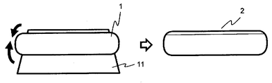
- the heat-resistant heat insulating material 11 was adhered to the surfaces of both end faces of the forging material 1 taken out from the heating furnace by a manipulator to obtain the hot forging material 2 (heat-resistant heat insulating material bonding step).
- the heat-resistant heat insulating material is kao wool (inorganic fiber), and as shown in Fig. 1, it is adhered to the surface that comes into contact with the metal bed or the tool to suppress the temperature drop of the hot forging material and to remove heat by contacting the metal bed or the tool.
- the temperature is about 5 to 10 ° C., which is usually lower than the temperature that drops before mounting. It was judged that there would be no problem in hot forging just because the temperature decreased.
- stationary forging was performed by hot free forging. After placing the hot forging material on the lower metal bed of the hot forging device used and placing the stationary forging tool on the upper end face of the hot forging die, the heat with a pressurizing capacity of 4000 tons. Free forging by pressing with an interforging device was performed to prepare a rough ground (hot forging material 3) to be used for hot forging in the next step (hot forging step). It was a free deformation region except for the portion where the lower metal bed and the stationary forging tool were in contact with the hot forging material.
- the forging start temperature was about 1000 ° C.
- the forging temperature during hot forging was about 950 to 980 ° C.
- Example 2 Temperature changes during hot forging and flaws in the hot forging material for the one to which the heat-resistant heat insulating material is adhered (Example 1 of the present invention) and the one to which the heat-resistant heat insulating material is not adhered (Comparative Example 1) using a waspaloy alloy. The degree of occurrence of (cracking) was compared. The pre-forging materials used were all ingots machined to predetermined dimensions, and the surface was roughened to a rough finish. In addition, stationary forging by hot free forging was performed using a material having an L / D of 1.5 or less as a material before heating.
- glass lubricant coating step approximately 50 glass lubricants are applied to both end faces (the faces that come into contact with the metal floor or the tool) of the preheating material of the present invention example 1 and the outer peripheral surface portion to which the heat-resistant heat insulating material is adhered. It was coated with a thickness of ⁇ 200 ⁇ m (glass lubricant coating step).
- This preheating material was heated to a predetermined hot forging temperature in a heating furnace (heating step). The oxygen concentration at this time was controlled to 2 to 8%.
- the heating temperature (hot forging temperature) was 1150 ° C., and the holding time was 2 to 4 hours.
- the temperature rising time to the forging temperature was about 8 hours.
- the present invention in which two pieces of kao wool (inorganic fibers) having different lengths (11A is long and 11B is short) are stacked in a cross shape as the heat-resistant heat insulating material 11 and taken out from a heating furnace with a manipulator.
- the forging material 1 of Example 2 was placed on the overlapped portion, and the heat-resistant heat insulating material was adhered to the surfaces of both end faces and the outer peripheral surface of the forging material while bending the inorganic heat insulating material in the direction of the black arrow.
- the heat-resistant heat insulating material 11B has a short length and is a length close to the total height of the forging material.
- the whole was wrapped and used as a material for hot forging (heat-resistant heat insulating material bonding process).
- the temperature drop of the hot forging material was suppressed, the heat removal due to contact with the metal pad or the tool was suppressed, and the heat removal due to contact with the grip portion of the manipulator was suppressed.
- the adhesion of the glass particles to the surface of the chaos wool to be bonded to the forging material completed the adhesion between the chaos wool and the forging material in a short time and without any problem. It was judged that there would be no problem in hot forging only because the temperature was lowered by about 5 to 10 ° C. as compared with the temperature lowered by the time of mounting.
- the forging material of Comparative Example 1 was not coated with a heat-resistant heat insulating material.
- Hot free forging was performed using the above-mentioned hot forging material. After placing the hot forging material on the lower metal bed of the hot forging device used and placing the stationary forging tool on the upper end face of the hot forging die, the heat with a pressurizing capacity of 10000 tons. Free forging by pressing with an interforging device was performed to prepare a rough ground (hot forging material) to be used for hot forging in the next step (hot forging step). It was a free deformation region except for the portion where the lower metal bed and the stationary forging tool were in contact with the hot forging material. The forging start temperature was about 1050 ° C., and the forging temperature during hot forging was about 1000 ° C.
- Example 1 of the present invention When the temperature of the hot forging material immediately after the stationary forging was measured with a radiation thermometer, it was about 1090 to 1120 ° C. in Example 1 of the present invention and 950 to 990 ° C. in Comparative Example 1. In Example 1 of the present invention, the temperature during hot forging could be maintained higher by about 100 ° C. or more. When the state of cracks in the produced hot forged material was confirmed, almost no cracks could be visually confirmed in the hot forged material of Example 1 of the present invention, but the hot forged material of Comparative Example 1 was found to have almost no cracks. Cracks that could be visually confirmed were confirmed on both end faces of the forging material that came into contact with the metal floor or the tool and on the side surfaces of the forging material that was gripped by the manipulator.
- Example 3 Temperature changes during forging and defects in the hot forging material (Example 2 of the present invention) and those without the heat-resistant heat insulating material (Comparative Example 2) using a waspaloy alloy. The degree of occurrence of cracks) was compared.
- the pre-heated material used was a material that had been forged after installation and machined to a predetermined size, and its surface had a surface roughness equivalent to a rough finish.
- a glass lubricant coating step Prior to the heating step, as a glass lubricant coating step, a glass lubricant was coated on both side end faces of the preheating material of the present invention 2 and a portion to which the heat-resistant heat insulating material was adhered to a thickness of about 50 to 200 ⁇ m (glass lubrication). Agent coating process).
- This preheating material was heated to a predetermined hot forging temperature in a heating furnace (heating step). The oxygen concentration at this time was controlled to 2 to 8%.
- the heating temperature was 1150 ° C. and the holding time was 2 to 4 hours.
- the temperature rising time to the forging temperature was about 8 hours.
- the heat-resistant heat insulating material 11 is prepared, the forging material 1 of Example 2 of the present invention taken out from the heating furnace by a manipulator is placed on the heat-resistant heat insulating material 11, and the heat-resistant heat insulating material is blackened. While bending in the direction of the arrow, a heat-resistant heat-insulating material was adhered to the surface of the outer peripheral surface to form a material for hot forging (heat-resistant heat-insulating material bonding process).
- the heat-resistant heat insulating material is kao wool (inorganic fiber), which is adhered to the outer peripheral surface (freely deformable part of the forging material) as shown in FIG. The heat removal was suppressed by this.
- the adhesion of the glass particles to the surface of the chaos wool to be bonded to the forging material completed the adhesion between the chaos wool and the forging material in a short time and without any problem. It was judged that there would be no problem in hot forging only because the temperature was lowered by about 5 to 10 ° C. as compared with the temperature lowered by the time of mounting.
- the forging material of Comparative Example 2 was not coated with a heat-resistant heat insulating material.
- Hot forging was performed using the above-mentioned hot forging material.
- the side surface of the hot forging material is sandwiched between the lower and upper metal sheets of the hot forging device, and forging is performed by pressing with the hot forging device with a pressurizing capacity of 4000 tons, which is used for hot forging in the next process.
- a wasteland (hot forging material) was produced (hot forging process).
- the forging start temperature was about 1050 ° C. in the uncoated part, and the forging material temperature in the place where the coating was peeled off during hot forging was about 1080 to 1020 ° C.
- the temperature of the hot forging material immediately after the completion of hot forging was measured with a radiation thermometer, it was 950 to 980 ° C.
- Example 2 of the present invention 900 to 950 ° C. in Comparative Example 2.
- the temperature during hot forging could be maintained about 50 to 80 ° C. higher.
- hot forging material of the present invention According to the method for producing a hot forging material of the present invention described above, even if a difficult-to-process alloy is used as a material for hot forging, hot forging can be efficiently performed while preventing defects such as cracks. It turns out that is possible.
Abstract
Description
ところで、熱間鍛造温度に加熱した熱間鍛造用素材を熱間鍛造開始するまでの温度低下や熱間鍛造中の温度低下が熱間加工性を低下させる代表的な合金に、難加工性合金として知られるγ’相(ガンマプライム相)の量を体積%で20%以上含むようなNi基合金やTi合金がある。これらの難加工性合金は、高温強度に優れているため、航空機部品や発電設備用部品に用いられる。これらの用途は、燃焼効率向上や発電効率向上を目的として製品の大型化の要求があるものや、γ’量を体積%で20%以上含むようなNi基合金(以下、γ’高含有Ni基合金)では、より高温での使用が検討されている。熱間鍛造温度が割れや疵の不良の発生に影響を及ぼし、特に、γ’高含有Ni基合金では、熱間鍛造可能な温度域が限定されるものもある。熱間加工性と割れなどの不良防止の両立が重要となり、熱間鍛造時の割れを防止しつつ、効率よく熱間鍛造する方法が求められている。
本発明の目的は、熱間鍛造用素材として難加工性合金を用いても、割れなどの不良を防止しつつ、効率よく熱間鍛造が可能な熱間鍛造材の製造方法を提供することである。 In the above-mentioned
By the way, difficult-to-process alloys are typical alloys in which the temperature drop until the start of hot forging and the temperature drop during hot forging reduce the hot workability of the hot forging material heated to the hot forging temperature. There are Ni-based alloys and Ti alloys containing 20% or more in volume% of the amount of γ'phase (gamma prime phase) known as. Since these difficult-to-process alloys have excellent high-temperature strength, they are used for aircraft parts and power generation equipment parts. These applications include those for which there is a demand for larger products for the purpose of improving combustion efficiency and power generation efficiency, and Ni-based alloys containing 20% or more of γ'in volume% (hereinafter, γ'high content Ni). Base alloys) are being considered for use at higher temperatures. The hot forging temperature affects the occurrence of cracks and defects, and in particular, some γ'high-containing Ni-based alloys have a limited temperature range in which hot forging is possible. It is important to achieve both hot workability and prevention of defects such as cracks, and there is a demand for a method for efficient hot forging while preventing cracks during hot forging.
An object of the present invention is to provide a method for producing a hot forging material capable of efficiently hot forging while preventing defects such as cracks even when a difficult-to-process alloy is used as a material for hot forging. be.
すなわち本発明は、熱間鍛造する加熱前素材を加熱炉中で熱間鍛造温度に加熱する加熱工程と、前記加熱炉から取り出した鍛造用素材の少なくともその表面の一部に、耐熱断熱材を接着させて熱間鍛造用素材とする耐熱断熱材接着工程と、金型、金敷、工具の何れかを用いて、前記熱間鍛造用素材の一部または全体を圧縮して所定の形状に成形する熱間鍛造工程と、を含む熱間鍛造材の製造方法である。
また本発明は、前記熱間鍛造工程が自由鍛造であり、前記自由鍛造で前記金型、金敷、工具の何れかに接触しない鍛造用素材の自由変形部分の少なくともその表面の一部に、前記耐熱断熱材を接着させる熱間鍛造材の製造方法である。
好ましくは、前記加熱前素材表面の、少なくとも前記耐熱断熱材を接着する部分にはガラス潤滑剤を被覆するガラス潤滑剤被覆工程を更に含む熱間鍛造材の製造方法である。
また、本発明において、前記耐熱断熱材の前記鍛造用素材と接着する面には、ガラス粒子が付着していても良い。
好ましくは、前記耐熱断熱材は無機繊維である熱間鍛造材の製造方法である。 The present invention has been made in view of the above-mentioned problems.
That is, in the present invention, a heat-resistant heat insulating material is applied to at least a part of the surface of the forging material taken out from the heating furnace and the heating step of heating the preheating material for hot forging to the hot forging temperature in the heating furnace. A part or all of the hot forging material is compressed into a predetermined shape by using the heat insulating material bonding process of bonding to make a hot forging material and any of a mold, a metal fitting, and a tool. It is a method of manufacturing a hot forging material including a hot forging step.
Further, in the present invention, the hot forging step is free forging, and at least a part of the surface of the free deformed portion of the forging material that does not come into contact with any of the mold, the die, and the tool in the free forging. This is a method for manufacturing a hot forged material that adheres a heat-resistant heat insulating material.
Preferably, it is a method for producing a hot forged material, further comprising a glass lubricant coating step of coating a glass lubricant on at least a portion of the surface of the preheating material to which the heat-resistant heat insulating material is adhered.
Further, in the present invention, glass particles may be attached to the surface of the heat-resistant heat insulating material that adheres to the forging material.
Preferably, the heat-resistant heat insulating material is a method for producing a hot forged material which is an inorganic fiber.
<加熱工程>
先ず、本発明では、熱間鍛造する加熱前素材を加熱炉中で熱間鍛造温度に加熱する。加熱前素材は、インゴット、ビレット、荒地、粉末成形体等、特に限定しないが、本発明の効果が最も発揮可能なものは、自由鍛造により所望の形状に成形を行うインゴットやビレットなどである。この加熱前素材を加熱炉中で熱間鍛造温度に加熱する。加熱の温度は加熱前素材の材質により異なり、例えば、Ni基合金では950~1180℃であれば良く、γ’高含有Ni基合金であれば1010~1180℃であれば良い。また、Ti合金であれば900~1180℃であれば良い。なお、本発明においては、加熱工程の後に“耐熱断熱材接着工程”を適用する。耐熱断熱材接着工程では、加熱炉から取り出した鍛造用素材に対して耐熱断熱材を接着させる。この耐熱断熱材を接着させるまでの間、鍛造用素材の温度低下がゼロであれば好ましいが、実際には少なからず温度低下する。そのため、熱間鍛造を開始するときの鍛造温度(鍛造開始温度)よりも5~100℃程度高めの温度を熱間鍛造温度に設定しても良い。このことにより、耐熱断熱材を接着しなければ、鍛造用素材の温度が、鍛造開始温度に対して100℃を超えて低下してしまうような場合でも、その温度低下を抑えることができて、熱間鍛造中の温度を高く保持できる。
また、加熱前素材の材質がNi基超耐熱合金である場合、殆どの合金でCrを10~35質量%の範囲で含有している。加熱工程中に加熱炉内の酸素とCrの反応を抑制する目的で、加熱炉内の酸素濃度を10%以下に制御するのが好ましい。好ましくは8%以下である。 Hereinafter, the present invention will be described step by step. The "material before heating" described below refers to the material before being charged into the heating furnace, and the "material for forging" refers to the material heated to the hot forging temperature in the heating furnace, and "heat". The "material for hot forging" means a material in which a heat-resistant heat insulating material is adhered to a predetermined part so that hot forging can be performed, and the "hot forging material" has a predetermined shape by a hot forging device. Refers to the molding material molded into.
<Heating process>
First, in the present invention, the preheating material to be hot forged is heated to the hot forging temperature in a heating furnace. The material before heating is not particularly limited, such as an ingot, billet, wasteland, powder molded body, etc., but the material in which the effect of the present invention can be most exhibited is an ingot or billet that is molded into a desired shape by free forging. This preheating material is heated to a hot forging temperature in a heating furnace. The heating temperature varies depending on the material of the material before heating. For example, the Ni-based alloy may be 950 to 1180 ° C., and the γ'high-containing Ni-based alloy may be 1010 to 1180 ° C. Further, if it is a Ti alloy, it may be 900 to 1180 ° C. In the present invention, the "heat-resistant heat insulating material bonding step" is applied after the heating step. In the heat-resistant heat insulating material bonding step, the heat-resistant heat insulating material is bonded to the forging material taken out from the heating furnace. It is preferable that the temperature drop of the forging material is zero until the heat-resistant heat insulating material is adhered, but in reality, the temperature drops not a little. Therefore, the hot forging temperature may be set to a temperature about 5 to 100 ° C. higher than the forging temperature (forging start temperature) at the start of hot forging. As a result, even if the temperature of the forging material drops by more than 100 ° C with respect to the forging start temperature unless the heat-resistant heat insulating material is adhered, the temperature drop can be suppressed. The temperature during hot forging can be kept high.
Further, when the material of the material before heating is a Ni-based super heat-resistant alloy, most of the alloys contain Cr in the range of 10 to 35% by mass. It is preferable to control the oxygen concentration in the heating furnace to 10% or less for the purpose of suppressing the reaction between oxygen and Cr in the heating furnace during the heating step. It is preferably 8% or less.
加熱前素材を熱間鍛造温度に加熱して、加熱炉から取り出した鍛造用素材の少なくとも表面の一部の所定の部分に耐熱断熱材を接着させて熱間鍛造用素材とする。接着させる部分は表面の一部であっても、表面全体であっても差し支えない。この鍛造用素材表面のどこの部分に耐熱断熱材を接着するかは、下記の2つの何れかを考慮とすると良い。
1つ目の方法は、割れが予想される部分の温度低下を優先的に防止する方法である。耐熱断熱材を鍛造用素材に接着させる作業の時間が長くなると、鍛造用素材の温度が低くなってしまい、熱間鍛造性を劣化させる場合がある。そのため、熱間鍛造性を損なわない時間で、必要最小限の範囲に耐熱断熱材をその表面に接着させることが好ましい。例えば、熱間鍛造用素材を熱間鍛造装置に載置したとき、例えば、下型(下金敷または下側工具)への抜熱が心配されるときは、下型(下金敷または下側工具)と接する面に耐熱断熱材を接着させても良いし、多角形の柱状の形状であれば、エッジ部分を含む範囲に接着させても良い。円柱状であれば、その側面に接着しても良い。つまり、熱間鍛造によって、割れなどの不良が発生しやすい場所を含んで耐熱断熱材を接着させると良い。この方法は、特に、難加工性合金として知られるγ’高含有Ni基合金に対して有効である。 <Heat-resistant heat insulating material bonding process>
The material before heating is heated to a hot forging temperature, and a heat-resistant heat insulating material is adhered to at least a predetermined part of the surface of the forging material taken out from the heating furnace to obtain a hot forging material. The portion to be bonded may be a part of the surface or the entire surface. One of the following two may be taken into consideration as to which part of the surface of the forging material the heat-resistant heat insulating material is to be adhered.
The first method is a method of preferentially preventing a temperature drop in a portion where cracks are expected. If the time required for adhering the heat-resistant heat insulating material to the forging material is long, the temperature of the forging material becomes low, which may deteriorate the hot forging property. Therefore, it is preferable to adhere the heat-resistant heat insulating material to the surface in the minimum necessary range within a time that does not impair the hot forging property. For example, when a hot forging material is placed on a hot forging device, for example, when there is concern about heat removal to the lower mold (lower metal floor or lower tool), the lower mold (lower metal floor or lower tool) ) May be adhered to the surface in contact with the heat-resistant heat insulating material, or if it has a polygonal columnar shape, it may be adhered to a range including the edge portion. If it is columnar, it may be adhered to the side surface thereof. That is, it is preferable to adhere the heat-resistant heat insulating material to the place where defects such as cracks are likely to occur by hot forging. This method is particularly effective for γ'high content Ni-based alloys known as hard-to-process alloys.
上記の方法の選択は、その材質や形状を考慮して選択すると良い。
この耐熱断熱材の接着により、熱間鍛造用素材の温度低下に伴う微細なγ’の析出を軽減する他、熱間鍛造用素材表層部の再結晶を促進させることが可能となることから、例えば、難加工性合金として知られるγ’高含有Ni基合金であっても、割れなどの不良の発生を軽減することができる。 The second method is a method of adhering the heat-resistant heat insulating material to at least a part of the surface of the freely deformable portion of the forging material. In this method, for example, when hot forging is free forging, the part that is not in contact with the upper mold (upper metal fitting or upper tool) or lower mold (lower metal fitting or lower tool) is allowed to cool in the atmosphere. Therefore, the main purpose is to reduce the temperature drop. This method can contribute to the reduction of flaws (cracks) because the heating temperature can be maintained in an alloy having a wide temperature range that can be hot forged, such as 718 alloys and waspaloys.
The above method may be selected in consideration of its material and shape.
By adhering the heat-resistant heat insulating material, it is possible to reduce the precipitation of fine γ'due to the temperature drop of the hot forging material and to promote the recrystallization of the surface layer of the hot forging material. For example, even a γ'high-containing Ni-based alloy known as a difficult-to-process alloy can reduce the occurrence of defects such as cracks.
一つ目の方法は「ガラス潤滑剤被覆工程」を行うことである。ガラス潤滑剤被覆工程は、前記加熱前素材表面の、少なくとも前記耐熱断熱材を接着する部分にガラス潤滑剤を予め被覆する工程を更に含むものである。ガラス潤滑剤は、前記加熱後の保温剤として作用することが可能であるため、特に、難加工性合金の熱間鍛造を行う場合に、有効である。
二つ目の方法は、前記耐熱断熱材の前記鍛造用素材と接着する面に、ガラス粒子を付着させておき、所定の場所に耐熱断熱材を接着させることである。この方法はガラス粒子が鍛造用素材表面の保有熱で軟化して接着させるものであるため、熱間鍛造温度が高いNi基超耐熱合金等の熱間鍛造への適用が有効である。なお、耐熱断熱材にガラス粒子を付着させる方法としては、例えば、前記耐熱断熱材の前記鍛造用素材と接着する面にガラス粒子を散布する方法、ガラス粒子を含んだガラス潤滑剤を塗布や噴霧(スプレー塗布)する方法がある。このうち、ガラス潤滑剤を塗布や噴霧(スプレー塗布)する方法を選択した場合、ガラス粒子を付着させた耐熱断熱材を乾燥させておくのが良い。前述したガラス潤滑剤を噴霧させる方法は、耐熱断熱材の前記鍛造用素材と接着する面に均一にガラス粒子を付着させることができ、特に好ましい。
なお、もちろん、上記の「ガラス潤滑剤被覆工程」と「耐熱断熱材の前記鍛造用素材と接着する面に、ガラス粒子を付着」させる2つの方法を組み合わせても差し支えない。 In the heat-resistant heat insulating material bonding step, in order to bond the heat-resistant heat insulating material easily and in a short time, a glass lubricant is provided between the heat-resistant heat insulating material and the bonding surface of the forging material to which the heat-resistant heat insulating material is bonded. It is preferable to keep it. The glass lubricant at this time mainly functions as an "adhesive". There are two ways to do this, each of which will be described.
The first method is to perform a "glass lubricant coating process". The glass lubricant coating step further includes a step of pre-coating at least the portion of the surface of the preheating material to which the heat-resistant heat insulating material is adhered with the glass lubricant. Since the glass lubricant can act as a heat retaining agent after heating, it is particularly effective when hot forging a difficult-to-process alloy.
The second method is to attach the glass particles to the surface of the heat-resistant heat insulating material to be adhered to the forging material, and to bond the heat-resistant heat insulating material to a predetermined place. Since this method softens and adheres the glass particles due to the heat retained on the surface of the forging material, it is effective for hot forging of Ni-based superheat resistant alloys having a high hot forging temperature. Examples of the method of adhering the glass particles to the heat-resistant heat insulating material include a method of spraying the glass particles on the surface of the heat-resistant heat insulating material to be adhered to the forging material, and a method of applying or spraying a glass lubricant containing the glass particles. There is a method of (spray application). Of these, when the method of applying or spraying (spraying) the glass lubricant is selected, it is preferable to dry the heat-resistant heat insulating material to which the glass particles are attached. The method of spraying the glass lubricant described above is particularly preferable because the glass particles can be uniformly adhered to the surface of the heat-resistant heat insulating material to be adhered to the forging material.
Of course, the above-mentioned "glass lubricant coating step" and the two methods of "adhering the glass particles to the surface of the heat-resistant heat insulating material to be adhered to the forging material" may be combined.
また、本発明のように、加熱炉から取り出した鍛造用素材の少なくともその表面の一部にカオウールを接着させると、熱間鍛造初期にもカオウールがそのまま維持され、熱間鍛造中の熱間鍛造用素材の温度低下も抑制できる。従来例のように、加熱炉装入前からカオウールを配置しておくと、温度と時間の関係によるが、熱間鍛造を行うための搬送時に、簡単に破砕されるような状態となる。 The heat-resistant heat insulating material is preferably an inorganic fiber. The "inorganic fiber" referred to in the present invention includes glass fiber, ceramic fiber and the like, and it is preferable to select a ceramic fiber having excellent heat insulating properties. Among the ceramic fibers, for example, KAOWOOL (registered trademark: hereinafter referred to as "kaowool") is particularly preferable because it is easily available and inexpensive. If the heat insulating material is an inorganic fiber, even if the surface roughness of the forging material is a little rough, it is easy to adhere along the surface shape, and the fiber is easily caught by the unevenness of the surface of the forging material. Since it is lightweight, it can be easily adhered to the side surface of the forging material, for example.
Further, as in the present invention, when chaos wool is adhered to at least a part of the surface of the forging material taken out from the heating furnace, the chaos wool is maintained as it is even in the initial stage of hot forging, and hot forging during hot forging is performed. It is also possible to suppress the temperature drop of the material. If the kao wool is placed before the heating furnace is charged as in the conventional example, it will be easily crushed during transportation for hot forging, depending on the relationship between temperature and time.
前述の熱間鍛造用素材を用いて、金型、金敷、工具の何れかを用いて、前記熱間鍛造用素材の一部または全体を圧縮して所定の形状に成形する。用いる鍛造装置は、難加工性合金であっても、所定の形状に成形可能な鍛造荷重が数千トン以上の大型の熱間鍛造装置であることが好ましい。
また、本発明において、前記熱間鍛造工程は自由鍛造であることが好ましい。自由鍛造を行うときの熱間鍛造用素材は重量も大きく、大気中に放熱する面積も広く、加工量も大きい。そのため、耐熱断熱材を接着させて、熱間鍛造用素材の温度低下抑制の効果が大きい。この場合、前述のように、例えば、718合金やワスパロイ等の熱間鍛造可能な温度域がやや広い一般的なNi基合金を熱間鍛造するのであれば、前記自由鍛造で前記金型、金敷、工具の何れかに接触しない鍛造用素材の自由変形部分の少なくともその表面の一部に、前記耐熱断熱材を接着させておくのが好ましい。 <Hot forging process>
Using the above-mentioned hot forging material, a part or the whole of the hot forging material is compressed and formed into a predetermined shape by using any of a mold, a die, and a tool. The forging device to be used is preferably a large-scale hot forging device having a forging load of several thousand tons or more that can be formed into a predetermined shape even if it is a difficult-to-process alloy.
Further, in the present invention, the hot forging step is preferably free forging. The material for hot forging when performing free forging is heavy, has a large area for heat dissipation to the atmosphere, and has a large amount of processing. Therefore, the heat-resistant heat insulating material is adhered, and the effect of suppressing the temperature drop of the hot forging material is great. In this case, as described above, for example, if a general Ni-based alloy such as 718 alloy or waspaloy, which has a slightly wide temperature range that can be hot forged, is hot forged, the mold and die can be forged by the free forging. It is preferable that the heat-resistant heat insulating material is adhered to at least a part of the surface of the freely deformable portion of the forging material that does not come into contact with any of the tools.
実施例1
加熱前素材として、718合金(Cr18.5質量%)及びワスパロイ合金(Cr19.5質量%)の他、Cr13.5質量%、Co25.0質量%、Mo2.8質量%、W1.2質量%、Ti6.2質量%、Al2.3質量%、C0.015質量%、B0.015質量%、Zr0.03質量%、残部Ni及び不可避的不純物でなる、γ’相をおおよそ49.5体積%含む、γ’高含有Ni基合金(以下、合金A)を用意した。前記加熱前素材は、何れもインゴットを所定の寸法に機械加工したもので、その表面は粗仕上げ相当の表面粗さとした。なお、熱間自由鍛造による据込鍛造を行うため、L/Dを3以下としたものを加熱前素材とした。 As an example, the present invention will be described in detail. Regarding the measurement temperature of the present invention example shown in the following examples, a part where the heat-resistant heat insulating material is not adhered, during hot forging, or after hot forging is completed. It was measured mainly on the peeled part.
Example 1
As the pre-heating material, in addition to 718 alloy (Cr18.5% by mass) and Waspaloy alloy (Cr19.5% by mass), Cr13.5% by mass, Co25.0% by mass, Mo2.8% by mass, W1.2% by mass. , Ti6.2% by mass, Al2.3% by mass, C0.015% by mass, B0.015% by mass, Zr0.03% by mass, balance Ni and unavoidable impurities, γ'phase is approximately 49.5% by mass. A γ'high content Ni-based alloy (hereinafter referred to as alloy A) containing the mixture was prepared. All of the materials before heating were made by machining an ingot to a predetermined size, and the surface thereof had a surface roughness equivalent to a rough finish. In addition, in order to perform stationary forging by hot free forging, a material having an L / D of 3 or less was used as the material before heating.
次に、加熱炉からマニピュレータで取り出した鍛造用素材1の両側端面の表面に耐熱断熱材11を接着させて熱間鍛造用素材2とした(耐熱断熱材接着工程)。耐熱断熱材はカオウール(無機繊維)とし、図1で示すように金敷または工具に接触する面に接着させ、熱間鍛造用素材の温度低下の抑制と、金敷または工具と接触することによる抜熱の抑制を行った。なお、予め被覆したガラス潤滑剤により、カオウールと鍛造用素材とは短時間で且つ、問題なく接着が完了したため、通常、載置までに低下する温度と比較しておおよそ5~10℃程度の温度が低下しただけで、熱間鍛造には支障がないものと判断した。 Prior to the heating step, as a glass lubricant coating step, at the time of the preheating material at 200 ° C. or lower, the glass lubricant is coated on both side end faces (the surface in contact with the metal bed or the tool) with a thickness of about 50 to 200 μm. (Glass lubricant coating process). This preheating material was heated to a predetermined hot forging temperature in a heating furnace (heating step). The oxygen concentration at this time was controlled to 2 to 8%. The heating temperature (hot forging temperature) was 1100 ° C. for the alloys A and 718, 1150 ° C. for the Wasparoi alloy, and the holding time was 2 to 9 hours. The temperature rise time to the hot forging temperature was about 8 hours, and the temperature could be raised to a predetermined temperature 10 hours or more earlier than in the conventional example in which the entire surface was wrapped with a heat-resistant heat insulating material.
Next, the heat-resistant
ワスパロイ合金を用いて、耐熱断熱材を接着させたもの(本発明例1)と、耐熱断熱材を接着しないもの(比較例1)について、熱間鍛造中の温度変化と熱間鍛造材の疵(割れ)の発生具合を比較した。
用いた鍛造前素材は、何れもインゴットを所定の寸法に機械加工したもので、その表面は粗仕上げ相当の表面粗さとした。なお、L/Dを1.5以下としたものを加熱前素材として熱間自由鍛造による据込鍛造を行った。 Example 2
Temperature changes during hot forging and flaws in the hot forging material for the one to which the heat-resistant heat insulating material is adhered (Example 1 of the present invention) and the one to which the heat-resistant heat insulating material is not adhered (Comparative Example 1) using a waspaloy alloy. The degree of occurrence of (cracking) was compared.
The pre-forging materials used were all ingots machined to predetermined dimensions, and the surface was roughened to a rough finish. In addition, stationary forging by hot free forging was performed using a material having an L / D of 1.5 or less as a material before heating.
次に、図2に示すように、耐熱断熱材11として長さの異なるカオウール(無機繊維)2枚(11Aが長く、11Bが短い)をクロス状に重ね、加熱炉からマニピュレータで取り出した本発明例2の鍛造用素材1を重ねた部分に載置し、無機断熱材を黒矢印の方向に折り曲げながら、鍛造用素材の両側端面及び外周面の表面に耐熱断熱材を接着させた。耐熱断熱材11Bは長さが短く、鍛造用素材の全高さ付近までの長さであり、長さの長い耐熱断熱材11Aは、鍛造用素材の上側端面部分で重ね、鍛造用素材のほぼ表面全体を包んで熱間鍛造用素材とした(耐熱断熱材接着工程)。これにより、熱間鍛造用素材の温度低下の抑制と、金敷または工具と接触することによる抜熱の抑制、マニピュレータの把持部と接触することによる抜熱の抑制を行った。なお、予め被覆したガラス潤滑剤に加えて、鍛造用素材と接着するカオウールの面へのガラス粒子の付着により、カオウールと鍛造用素材とは短時間で且つ、問題なく接着が完了したため、通常、載置までに低下する温度と比較しておおよそ5~10℃程度の温度が低下しただけで、熱間鍛造には支障がないものと判断した。なお、比較例1の鍛造用素材には、耐熱断熱材の被覆は行わなかった。 Prior to the heating step, as a glass lubricant coating step, approximately 50 glass lubricants are applied to both end faces (the faces that come into contact with the metal floor or the tool) of the preheating material of the present invention example 1 and the outer peripheral surface portion to which the heat-resistant heat insulating material is adhered. It was coated with a thickness of ~ 200 μm (glass lubricant coating step). This preheating material was heated to a predetermined hot forging temperature in a heating furnace (heating step). The oxygen concentration at this time was controlled to 2 to 8%. The heating temperature (hot forging temperature) was 1150 ° C., and the holding time was 2 to 4 hours. The temperature rising time to the forging temperature was about 8 hours.
Next, as shown in FIG. 2, the present invention in which two pieces of kao wool (inorganic fibers) having different lengths (11A is long and 11B is short) are stacked in a cross shape as the heat-resistant
据込鍛造直後の熱間鍛造用素材の温度を放射温度計で測定したところ、本発明例1ではおおよそ1090~1120℃であり、比較例1は950~990℃であった。本発明例1の方が熱間鍛造中の温度を約100℃以上高く保持できた。作製した熱間鍛造材の割れの状況を確認したところ、本発明例1の熱間鍛造材には目視で殆ど割れの発生が確認できなかったが、比較例1の熱間鍛造材には、金敷または工具と接触する鍛造用素材の両側端面やマニピュレータで把持する鍛造用素材側面で目視で確認できるだけの割れが確認できた。 Hot free forging was performed using the above-mentioned hot forging material. After placing the hot forging material on the lower metal bed of the hot forging device used and placing the stationary forging tool on the upper end face of the hot forging die, the heat with a pressurizing capacity of 10000 tons. Free forging by pressing with an interforging device was performed to prepare a rough ground (hot forging material) to be used for hot forging in the next step (hot forging step). It was a free deformation region except for the portion where the lower metal bed and the stationary forging tool were in contact with the hot forging material. The forging start temperature was about 1050 ° C., and the forging temperature during hot forging was about 1000 ° C.
When the temperature of the hot forging material immediately after the stationary forging was measured with a radiation thermometer, it was about 1090 to 1120 ° C. in Example 1 of the present invention and 950 to 990 ° C. in Comparative Example 1. In Example 1 of the present invention, the temperature during hot forging could be maintained higher by about 100 ° C. or more. When the state of cracks in the produced hot forged material was confirmed, almost no cracks could be visually confirmed in the hot forged material of Example 1 of the present invention, but the hot forged material of Comparative Example 1 was found to have almost no cracks. Cracks that could be visually confirmed were confirmed on both end faces of the forging material that came into contact with the metal floor or the tool and on the side surfaces of the forging material that was gripped by the manipulator.
ワスパロイ合金を用いて、耐熱断熱材を接着させたもの(本発明例2)と、耐熱断熱材を接着しないもの(比較例2)について、鍛伸中の温度変化と熱間鍛造材の疵(割れ)の発生具合を比較した。
用いた加熱前素材は、据込鍛造後の素材を所定の寸法に機械加工したもので、その表面は粗仕上げ相当の表面粗さとした。 Example 3
Temperature changes during forging and defects in the hot forging material (Example 2 of the present invention) and those without the heat-resistant heat insulating material (Comparative Example 2) using a waspaloy alloy. The degree of occurrence of cracks) was compared.
The pre-heated material used was a material that had been forged after installation and machined to a predetermined size, and its surface had a surface roughness equivalent to a rough finish.
次に、図3に示すように、耐熱断熱材11を準備し、加熱炉からマニピュレータで取り出した本発明例2の鍛造用素材1を耐熱断熱材11上に載置し、耐熱断熱材を黒矢印の方向に曲げながら、外周面の表面に耐熱断熱材を接着させて熱間鍛造用素材とした(耐熱断熱材接着工程)。耐熱断熱材はカオウール(無機繊維)とし、図3で示すように外周面(鍛造用素材の自由変形部分)に接着させ、熱間鍛造用素材の温度低下の抑制と、マニピュレータの把持部と接触することによる抜熱の抑制を行った。なお、予め被覆したガラス潤滑剤に加えて、鍛造用素材と接着するカオウールの面へのガラス粒子の付着により、カオウールと鍛造用素材とは短時間で且つ、問題なく接着が完了したため、通常、載置までに低下する温度と比較しておおよそ5~10℃程度の温度が低下しただけで、熱間鍛造には支障がないものと判断した。なお、比較例2の鍛造用素材には、耐熱断熱材の被覆は行わなかった。 Prior to the heating step, as a glass lubricant coating step, a glass lubricant was coated on both side end faces of the preheating material of the
Next, as shown in FIG. 3, the heat-resistant
熱間鍛造終了直後の熱間鍛造用素材の温度を放射温度計で測定したところ、本発明例2では950~980℃であり、比較例2は900~950℃であった。本発明例2の方が、熱間鍛造中の温度を約50~80℃高く保持できた。作製した熱間鍛造材の割れの状況を確認したところ、本発明例2の熱間鍛造材には目視で殆ど割れの発生が確認できなかったが、比較例2の熱間鍛造材には、目視で確認できるだけの割れが全体的に確認できた。 Hot forging was performed using the above-mentioned hot forging material. The side surface of the hot forging material is sandwiched between the lower and upper metal sheets of the hot forging device, and forging is performed by pressing with the hot forging device with a pressurizing capacity of 4000 tons, which is used for hot forging in the next process. A wasteland (hot forging material) was produced (hot forging process). The forging start temperature was about 1050 ° C. in the uncoated part, and the forging material temperature in the place where the coating was peeled off during hot forging was about 1080 to 1020 ° C.
When the temperature of the hot forging material immediately after the completion of hot forging was measured with a radiation thermometer, it was 950 to 980 ° C. in Example 2 of the present invention and 900 to 950 ° C. in Comparative Example 2. In Example 2 of the present invention, the temperature during hot forging could be maintained about 50 to 80 ° C. higher. When the state of cracks in the produced hot forged material was confirmed, almost no cracks could be visually confirmed in the hot forged material of Example 2 of the present invention, but the hot forged material of Comparative Example 2 was found to have almost no cracks. The cracks that could be visually confirmed were confirmed as a whole.
2 熱間鍛造用素材
3 熱間鍛造材
11 耐熱断熱材
1 Forging
Claims (5)
- 熱間鍛造する加熱前素材を加熱炉中で熱間鍛造温度に加熱する加熱工程と、
前記加熱炉から取り出した鍛造用素材の少なくともその表面の一部に、耐熱断熱材を接着させて熱間鍛造用素材とする耐熱断熱材接着工程と、
金型、金敷、工具の何れかを用いて、前記熱間鍛造用素材の一部または全体を圧縮して所定の形状に成形する熱間鍛造工程と、
を含む熱間鍛造材の製造方法。 Hot forging A heating process that heats the preheating material to the hot forging temperature in a heating furnace,
A heat-resistant heat insulating material bonding step of bonding a heat-resistant heat insulating material to at least a part of the surface of the forging material taken out from the heating furnace to obtain a hot forging material.
A hot forging process in which a part or the whole of the hot forging material is compressed and formed into a predetermined shape using any of a mold, a die, and a tool.
A method for manufacturing a hot forged material including. - 前記熱間鍛造工程が自由鍛造であり、前記自由鍛造で前記金型、金敷、工具の何れかに接触しない鍛造用素材の自由変形部分の少なくともその表面の一部に、前記耐熱断熱材を接着させる請求項1に記載の熱間鍛造材の製造方法。 The hot forging process is free forging, and the heat-resistant heat insulating material is adhered to at least a part of the surface of a free-deformable portion of the forging material that does not come into contact with any of the mold, die, and tool in the free forging. The method for producing a hot forged material according to claim 1.
- 前記加熱前素材表面の、少なくとも前記耐熱断熱材を接着する部分にはガラス潤滑剤を被覆するガラス潤滑剤被覆工程を更に含む請求項1または2に記載の熱間鍛造材の製造方法。 The method for producing a hot forged material according to claim 1 or 2, further comprising a glass lubricant coating step of coating a glass lubricant on at least a portion of the surface of the preheating material to which the heat-resistant heat insulating material is adhered.
- 前記耐熱断熱材の前記鍛造用素材と接着する面には、ガラス粒子が付着している請求項1乃至3の何れかに記載の熱間鍛造材の製造方法。 The method for producing a hot forging material according to any one of claims 1 to 3, wherein glass particles are attached to the surface of the heat-resistant heat insulating material that adheres to the forging material.
- 前記耐熱断熱材は無機繊維である請求項1乃至4の何れかに記載の熱間鍛造材の製造方法。
The method for producing a hot forged material according to any one of claims 1 to 4, wherein the heat-resistant heat insulating material is an inorganic fiber.
Priority Applications (6)
| Application Number | Priority Date | Filing Date | Title |
|---|---|---|---|
| EP21767360.7A EP4119257A4 (en) | 2020-03-13 | 2021-03-12 | Method for manufacturing hot-forged member |
| US17/904,697 US20230068369A1 (en) | 2020-03-13 | 2021-03-12 | Method for manufacturing hot-forged member |
| JP2022507302A JP7335561B2 (en) | 2020-03-13 | 2021-03-12 | Method for manufacturing hot forged material |
| CN202180020641.1A CN115279513A (en) | 2020-03-13 | 2021-03-12 | Method for producing hot forged material |
| AU2021233462A AU2021233462A1 (en) | 2020-03-13 | 2021-03-12 | Method for manufacturing hot-forged member |
| JP2023103225A JP7428290B2 (en) | 2020-03-13 | 2023-06-23 | Method for manufacturing hot forged materials |
Applications Claiming Priority (2)
| Application Number | Priority Date | Filing Date | Title |
|---|---|---|---|
| JP2020-044483 | 2020-03-13 | ||
| JP2020044483 | 2020-03-13 |
Publications (1)
| Publication Number | Publication Date |
|---|---|
| WO2021182606A1 true WO2021182606A1 (en) | 2021-09-16 |
Family
ID=77671582
Family Applications (1)
| Application Number | Title | Priority Date | Filing Date |
|---|---|---|---|
| PCT/JP2021/010022 WO2021182606A1 (en) | 2020-03-13 | 2021-03-12 | Method for manufacturing hot-forged member |
Country Status (6)
| Country | Link |
|---|---|
| US (1) | US20230068369A1 (en) |
| EP (1) | EP4119257A4 (en) |
| JP (2) | JP7335561B2 (en) |
| CN (1) | CN115279513A (en) |
| AU (1) | AU2021233462A1 (en) |
| WO (1) | WO2021182606A1 (en) |
Cited By (1)
| Publication number | Priority date | Publication date | Assignee | Title |
|---|---|---|---|---|
| WO2023037667A1 (en) * | 2021-09-10 | 2023-03-16 | 株式会社プロテリアル | Method for producing hot-forged member |
Citations (6)
| Publication number | Priority date | Publication date | Assignee | Title |
|---|---|---|---|---|
| JPS6040492B2 (en) * | 1980-08-07 | 1985-09-11 | 新日本製鐵株式会社 | How to keep hot metal pieces warm |
| JPS6121287B2 (en) * | 1981-02-23 | 1986-05-26 | Nippon Seikosho Kk | |
| JPH05177289A (en) * | 1991-12-26 | 1993-07-20 | Daido Steel Co Ltd | Method for preventing heat loss in die forging |
| WO2012090892A1 (en) * | 2010-12-28 | 2012-07-05 | 日立金属株式会社 | Closed-die forging method and method of manufacturing forged article |
| JP2014508857A (en) | 2011-01-17 | 2014-04-10 | エイティーアイ・プロパティーズ・インコーポレーテッド | Improving hot workability of metal alloys through surface coating |
| JP6311973B2 (en) * | 2013-04-01 | 2018-04-18 | 日立金属株式会社 | Hot forging method |
Family Cites Families (8)
| Publication number | Priority date | Publication date | Assignee | Title |
|---|---|---|---|---|
| CN100386558C (en) * | 2005-02-03 | 2008-05-07 | 宝钢集团上海五钢有限公司 | Sticking adiabatic cotton and method of making the same |
| JP6379933B2 (en) | 2014-09-29 | 2018-08-29 | 新日鐵住金株式会社 | Alloy manufacturing method |
| WO2016052523A1 (en) | 2014-09-29 | 2016-04-07 | 日立金属株式会社 | METHOD FOR PRODUCING Ni-BASED SUPER HEAT-RESISTANT ALLOY |
| JP6476704B2 (en) | 2014-09-30 | 2019-03-06 | 日立金属株式会社 | Nickel base casting alloy and hot forging die |
| CN105479106B (en) * | 2015-12-18 | 2016-10-19 | 贵州航宇科技发展股份有限公司 | The forging forming method of 718Plus alloy |
| CN105478643A (en) * | 2015-12-24 | 2016-04-13 | 中国第二重型机械集团德阳万航模锻有限责任公司 | GH864 high-temperature alloy die forging method |
| CN106040928B (en) * | 2016-05-30 | 2017-10-31 | 中国航空工业集团公司北京航空材料研究院 | The especially big whole frame forging part hot forming thermal sheathing process of Type Titanium Alloy |
| CN113122789B (en) | 2016-11-16 | 2022-07-08 | 三菱重工业株式会社 | Nickel-based alloy mold and repair method thereof |
-
2021
- 2021-03-12 EP EP21767360.7A patent/EP4119257A4/en active Pending
- 2021-03-12 CN CN202180020641.1A patent/CN115279513A/en active Pending
- 2021-03-12 AU AU2021233462A patent/AU2021233462A1/en active Pending
- 2021-03-12 WO PCT/JP2021/010022 patent/WO2021182606A1/en active Application Filing
- 2021-03-12 JP JP2022507302A patent/JP7335561B2/en active Active
- 2021-03-12 US US17/904,697 patent/US20230068369A1/en active Pending
-
2023
- 2023-06-23 JP JP2023103225A patent/JP7428290B2/en active Active
Patent Citations (7)
| Publication number | Priority date | Publication date | Assignee | Title |
|---|---|---|---|---|
| JPS6040492B2 (en) * | 1980-08-07 | 1985-09-11 | 新日本製鐵株式会社 | How to keep hot metal pieces warm |
| JPS6121287B2 (en) * | 1981-02-23 | 1986-05-26 | Nippon Seikosho Kk | |
| JPH05177289A (en) * | 1991-12-26 | 1993-07-20 | Daido Steel Co Ltd | Method for preventing heat loss in die forging |
| WO2012090892A1 (en) * | 2010-12-28 | 2012-07-05 | 日立金属株式会社 | Closed-die forging method and method of manufacturing forged article |
| JP2014508857A (en) | 2011-01-17 | 2014-04-10 | エイティーアイ・プロパティーズ・インコーポレーテッド | Improving hot workability of metal alloys through surface coating |
| JP6141499B2 (en) * | 2011-01-17 | 2017-06-07 | エイティーアイ・プロパティーズ・エルエルシー | Improving hot workability of metal alloys through surface coating |
| JP6311973B2 (en) * | 2013-04-01 | 2018-04-18 | 日立金属株式会社 | Hot forging method |
Cited By (1)
| Publication number | Priority date | Publication date | Assignee | Title |
|---|---|---|---|---|
| WO2023037667A1 (en) * | 2021-09-10 | 2023-03-16 | 株式会社プロテリアル | Method for producing hot-forged member |
Also Published As
| Publication number | Publication date |
|---|---|
| EP4119257A4 (en) | 2023-08-09 |
| JPWO2021182606A1 (en) | 2021-09-16 |
| US20230068369A1 (en) | 2023-03-02 |
| EP4119257A1 (en) | 2023-01-18 |
| JP7428290B2 (en) | 2024-02-06 |
| AU2021233462A1 (en) | 2022-10-06 |
| JP7335561B2 (en) | 2023-08-30 |
| CN115279513A (en) | 2022-11-01 |
| JP2023116806A (en) | 2023-08-22 |
Similar Documents
| Publication | Publication Date | Title |
|---|---|---|
| JP6931679B2 (en) | How to form a surface coating on a work piece of alloy | |
| US10207312B2 (en) | Lubrication processes for enhanced forgeability | |
| US20180281049A1 (en) | Method of producing forged product | |
| WO2021182606A1 (en) | Method for manufacturing hot-forged member | |
| CN110508735B (en) | Increment constraint multidirectional forging method for silicon carbide whisker reinforced aluminum matrix composite | |
| WO2023037667A1 (en) | Method for producing hot-forged member | |
| JPH02212373A (en) | Method compounding ceramics |
Legal Events
| Date | Code | Title | Description |
|---|---|---|---|
| 121 | Ep: the epo has been informed by wipo that ep was designated in this application |
Ref document number: 21767360 Country of ref document: EP Kind code of ref document: A1 |
|
| ENP | Entry into the national phase |
Ref document number: 2022507302 Country of ref document: JP Kind code of ref document: A |
|
| ENP | Entry into the national phase |
Ref document number: 2021233462 Country of ref document: AU Date of ref document: 20210312 Kind code of ref document: A |
|
| WWE | Wipo information: entry into national phase |
Ref document number: 2021767360 Country of ref document: EP |
|
| ENP | Entry into the national phase |
Ref document number: 2021767360 Country of ref document: EP Effective date: 20221013 |
|
| NENP | Non-entry into the national phase |
Ref country code: DE |