WO2021182259A1 - Arc detection device, power conditioner, indoor wiring system, circuit breaker, solar panel, solar panel attachment module, and junction box - Google Patents
Arc detection device, power conditioner, indoor wiring system, circuit breaker, solar panel, solar panel attachment module, and junction box Download PDFInfo
- Publication number
- WO2021182259A1 WO2021182259A1 PCT/JP2021/008291 JP2021008291W WO2021182259A1 WO 2021182259 A1 WO2021182259 A1 WO 2021182259A1 JP 2021008291 W JP2021008291 W JP 2021008291W WO 2021182259 A1 WO2021182259 A1 WO 2021182259A1
- Authority
- WO
- WIPO (PCT)
- Prior art keywords
- wiring
- arc
- branch
- detection device
- devices
- Prior art date
Links
- 238000001514 detection method Methods 0.000 title claims abstract description 112
- 230000005611 electricity Effects 0.000 claims description 4
- 238000001228 spectrum Methods 0.000 description 18
- 238000010586 diagram Methods 0.000 description 16
- 238000012986 modification Methods 0.000 description 15
- 230000004048 modification Effects 0.000 description 15
- 238000010248 power generation Methods 0.000 description 14
- 239000003990 capacitor Substances 0.000 description 3
- 230000000149 penetrating effect Effects 0.000 description 3
- 230000005856 abnormality Effects 0.000 description 1
- 230000032683 aging Effects 0.000 description 1
- 230000000903 blocking effect Effects 0.000 description 1
- 230000006866 deterioration Effects 0.000 description 1
- 238000010891 electric arc Methods 0.000 description 1
- 239000000463 material Substances 0.000 description 1
- 238000000034 method Methods 0.000 description 1
- 239000004065 semiconductor Substances 0.000 description 1
Images


Classifications
-
- H—ELECTRICITY
- H02—GENERATION; CONVERSION OR DISTRIBUTION OF ELECTRIC POWER
- H02S—GENERATION OF ELECTRIC POWER BY CONVERSION OF INFRARED RADIATION, VISIBLE LIGHT OR ULTRAVIOLET LIGHT, e.g. USING PHOTOVOLTAIC [PV] MODULES
- H02S50/00—Monitoring or testing of PV systems, e.g. load balancing or fault identification
- H02S50/10—Testing of PV devices, e.g. of PV modules or single PV cells
-
- G—PHYSICS
- G01—MEASURING; TESTING
- G01R—MEASURING ELECTRIC VARIABLES; MEASURING MAGNETIC VARIABLES
- G01R31/00—Arrangements for testing electric properties; Arrangements for locating electric faults; Arrangements for electrical testing characterised by what is being tested not provided for elsewhere
- G01R31/12—Testing dielectric strength or breakdown voltage ; Testing or monitoring effectiveness or level of insulation, e.g. of a cable or of an apparatus, for example using partial discharge measurements; Electrostatic testing
- G01R31/1227—Testing dielectric strength or breakdown voltage ; Testing or monitoring effectiveness or level of insulation, e.g. of a cable or of an apparatus, for example using partial discharge measurements; Electrostatic testing of components, parts or materials
- G01R31/1263—Testing dielectric strength or breakdown voltage ; Testing or monitoring effectiveness or level of insulation, e.g. of a cable or of an apparatus, for example using partial discharge measurements; Electrostatic testing of components, parts or materials of solid or fluid materials, e.g. insulation films, bulk material; of semiconductors or LV electronic components or parts; of cable, line or wire insulation
-
- G—PHYSICS
- G01—MEASURING; TESTING
- G01R—MEASURING ELECTRIC VARIABLES; MEASURING MAGNETIC VARIABLES
- G01R31/00—Arrangements for testing electric properties; Arrangements for locating electric faults; Arrangements for electrical testing characterised by what is being tested not provided for elsewhere
- G01R31/12—Testing dielectric strength or breakdown voltage ; Testing or monitoring effectiveness or level of insulation, e.g. of a cable or of an apparatus, for example using partial discharge measurements; Electrostatic testing
- G01R31/14—Circuits therefor, e.g. for generating test voltages, sensing circuits
-
- G—PHYSICS
- G01—MEASURING; TESTING
- G01R—MEASURING ELECTRIC VARIABLES; MEASURING MAGNETIC VARIABLES
- G01R31/00—Arrangements for testing electric properties; Arrangements for locating electric faults; Arrangements for electrical testing characterised by what is being tested not provided for elsewhere
- G01R31/40—Testing power supplies
-
- H—ELECTRICITY
- H02—GENERATION; CONVERSION OR DISTRIBUTION OF ELECTRIC POWER
- H02H—EMERGENCY PROTECTIVE CIRCUIT ARRANGEMENTS
- H02H1/00—Details of emergency protective circuit arrangements
- H02H1/0007—Details of emergency protective circuit arrangements concerning the detecting means
- H02H1/0015—Using arc detectors
-
- H—ELECTRICITY
- H02—GENERATION; CONVERSION OR DISTRIBUTION OF ELECTRIC POWER
- H02H—EMERGENCY PROTECTIVE CIRCUIT ARRANGEMENTS
- H02H3/00—Emergency protective circuit arrangements for automatic disconnection directly responsive to an undesired change from normal electric working condition with or without subsequent reconnection ; integrated protection
- H02H3/26—Emergency protective circuit arrangements for automatic disconnection directly responsive to an undesired change from normal electric working condition with or without subsequent reconnection ; integrated protection responsive to difference between voltages or between currents; responsive to phase angle between voltages or between currents
- H02H3/32—Emergency protective circuit arrangements for automatic disconnection directly responsive to an undesired change from normal electric working condition with or without subsequent reconnection ; integrated protection responsive to difference between voltages or between currents; responsive to phase angle between voltages or between currents involving comparison of the voltage or current values at corresponding points in different conductors of a single system, e.g. of currents in go and return conductors
- H02H3/33—Emergency protective circuit arrangements for automatic disconnection directly responsive to an undesired change from normal electric working condition with or without subsequent reconnection ; integrated protection responsive to difference between voltages or between currents; responsive to phase angle between voltages or between currents involving comparison of the voltage or current values at corresponding points in different conductors of a single system, e.g. of currents in go and return conductors using summation current transformers
-
- H—ELECTRICITY
- H02—GENERATION; CONVERSION OR DISTRIBUTION OF ELECTRIC POWER
- H02H—EMERGENCY PROTECTIVE CIRCUIT ARRANGEMENTS
- H02H7/00—Emergency protective circuit arrangements specially adapted for specific types of electric machines or apparatus or for sectionalised protection of cable or line systems, and effecting automatic switching in the event of an undesired change from normal working conditions
- H02H7/20—Emergency protective circuit arrangements specially adapted for specific types of electric machines or apparatus or for sectionalised protection of cable or line systems, and effecting automatic switching in the event of an undesired change from normal working conditions for electronic equipment
-
- H—ELECTRICITY
- H02—GENERATION; CONVERSION OR DISTRIBUTION OF ELECTRIC POWER
- H02H—EMERGENCY PROTECTIVE CIRCUIT ARRANGEMENTS
- H02H7/00—Emergency protective circuit arrangements specially adapted for specific types of electric machines or apparatus or for sectionalised protection of cable or line systems, and effecting automatic switching in the event of an undesired change from normal working conditions
- H02H7/26—Sectionalised protection of cable or line systems, e.g. for disconnecting a section on which a short-circuit, earth fault, or arc discharge has occured
- H02H7/268—Sectionalised protection of cable or line systems, e.g. for disconnecting a section on which a short-circuit, earth fault, or arc discharge has occured for dc systems
-
- H—ELECTRICITY
- H02—GENERATION; CONVERSION OR DISTRIBUTION OF ELECTRIC POWER
- H02S—GENERATION OF ELECTRIC POWER BY CONVERSION OF INFRARED RADIATION, VISIBLE LIGHT OR ULTRAVIOLET LIGHT, e.g. USING PHOTOVOLTAIC [PV] MODULES
- H02S40/00—Components or accessories in combination with PV modules, not provided for in groups H02S10/00 - H02S30/00
- H02S40/30—Electrical components
-
- H—ELECTRICITY
- H02—GENERATION; CONVERSION OR DISTRIBUTION OF ELECTRIC POWER
- H02H—EMERGENCY PROTECTIVE CIRCUIT ARRANGEMENTS
- H02H7/00—Emergency protective circuit arrangements specially adapted for specific types of electric machines or apparatus or for sectionalised protection of cable or line systems, and effecting automatic switching in the event of an undesired change from normal working conditions
- H02H7/10—Emergency protective circuit arrangements specially adapted for specific types of electric machines or apparatus or for sectionalised protection of cable or line systems, and effecting automatic switching in the event of an undesired change from normal working conditions for converters; for rectifiers
- H02H7/12—Emergency protective circuit arrangements specially adapted for specific types of electric machines or apparatus or for sectionalised protection of cable or line systems, and effecting automatic switching in the event of an undesired change from normal working conditions for converters; for rectifiers for static converters or rectifiers
- H02H7/1213—Emergency protective circuit arrangements specially adapted for specific types of electric machines or apparatus or for sectionalised protection of cable or line systems, and effecting automatic switching in the event of an undesired change from normal working conditions for converters; for rectifiers for static converters or rectifiers for DC-DC converters
-
- H—ELECTRICITY
- H02—GENERATION; CONVERSION OR DISTRIBUTION OF ELECTRIC POWER
- H02S—GENERATION OF ELECTRIC POWER BY CONVERSION OF INFRARED RADIATION, VISIBLE LIGHT OR ULTRAVIOLET LIGHT, e.g. USING PHOTOVOLTAIC [PV] MODULES
- H02S50/00—Monitoring or testing of PV systems, e.g. load balancing or fault identification
-
- Y—GENERAL TAGGING OF NEW TECHNOLOGICAL DEVELOPMENTS; GENERAL TAGGING OF CROSS-SECTIONAL TECHNOLOGIES SPANNING OVER SEVERAL SECTIONS OF THE IPC; TECHNICAL SUBJECTS COVERED BY FORMER USPC CROSS-REFERENCE ART COLLECTIONS [XRACs] AND DIGESTS
- Y02—TECHNOLOGIES OR APPLICATIONS FOR MITIGATION OR ADAPTATION AGAINST CLIMATE CHANGE
- Y02E—REDUCTION OF GREENHOUSE GAS [GHG] EMISSIONS, RELATED TO ENERGY GENERATION, TRANSMISSION OR DISTRIBUTION
- Y02E10/00—Energy generation through renewable energy sources
- Y02E10/50—Photovoltaic [PV] energy
Definitions
- the present invention relates to an arc detection device, a power conditioner, an indoor wiring system, a breaker, a solar panel, a module attached to the solar panel, and a junction box.
- branch wiring wiring that branches from one DC power supply to each of the multiple devices.
- an arc may be generated for each of the path before branching and the plurality of paths after branching of the branch wiring. If arc detection means are provided for each of the pre-branch route and the post-branch route of the branch wiring, the arc can be detected for each of the pre-branch route and the post-branch route, but the system can detect the arc. The size will increase and the cost will increase.
- the present invention provides an arc detection device or the like that can easily detect an arc generated in a branch wiring.
- One aspect of the arc detection device is a first wiring on a first wiring that connects a positive electrode of a DC power supply and a plurality of devices and branches from the positive electrode of the DC power supply to each of the plurality of devices.
- the node is connected to the negative electrode of the DC power supply and the plurality of devices, and is connected between the negative electrode of the DC power supply and the second node on the second wiring branching to each of the plurality of devices.
- the generation of an arc is determined based on a low-impedance circuit having a lower impedance than that of each of the plurality of devices, a current detection unit that detects a current flowing through the low-impedance circuit, and a current detected by the current detection unit. It is provided with an arc determination unit.
- One aspect of the power conditioner according to the present invention includes the above arc detection device and a converter that converts the output power of the DC power supply.
- One aspect of the indoor wiring system according to the present invention includes the arc detection device, the first wiring, the second wiring, and the plurality of devices installed indoors.
- One aspect of the breaker according to the present invention is provided with the above-mentioned arc detection device, and when it is determined that an arc has been generated, the current flowing through the first wiring and the second wiring is cut off.
- One aspect of the solar panel according to the present invention is provided with the above-mentioned arc detection device and generates electricity by sunlight.
- One aspect of the module attached to the solar panel according to the present invention is provided with the above-mentioned arc detection device and converts the signal output from the solar panel.
- junction box is provided with the above-mentioned arc detection device, and connects the solar panel and the power conditioner.
- an arc generated in a branch wiring can be easily detected.
- FIG. 1 is a configuration diagram showing an example of a photovoltaic power generation system according to the first embodiment.
- FIG. 2A is a diagram showing a frequency spectrum of a current flowing through the point A1 when an arc is generated at the point A1.
- FIG. 2B is a diagram showing a frequency spectrum of a current flowing through the point A2 when an arc is generated at the point A1.
- FIG. 2C is a diagram showing a frequency spectrum of currents flowing through points A3 and A4 when an arc is generated at point A1.
- FIG. 3 is a configuration diagram showing an example of a photovoltaic power generation system according to the first modification of the first embodiment.
- FIG. 4 is a configuration diagram showing an example of a photovoltaic power generation system according to the second modification of the first embodiment.
- FIG. 5 is a configuration diagram showing an example of the indoor wiring system according to the second embodiment.
- FIG. 6 is a diagram for explaining an application example of the arc detection device according to the present invention.
- FIG. 1 is a configuration diagram showing an example of a photovoltaic power generation system 1a according to the first embodiment.
- the photovoltaic power generation system 1a includes a solar panel 41, storage batteries 54, 55 and 56, DC / DC converters 51, 52 and 53, and a power conditioner (power conditioner) 60a.
- the solar panel 41 generates electricity by sunlight and generates DC power.
- the DC power generated by the solar panel 41 is supplied to the power conditioner 60a.
- the storage battery 54 stores the DC power from the DC / DC converter 51
- the storage battery 55 stores the DC power from the DC / DC converter 52
- the storage battery 56 stores the DC power from the DC / DC converter 53.
- the storage batteries 54, 55, and 56 may be mounted on an electric vehicle, an electric bicycle, or the like, or may be used for supplying power to household electric appliances or the like.
- the DC / DC converters 51, 52, and 53 are voltage converters that boost or step down the DC voltage of the supplied DC power and output it.
- the DC / DC converter 51 boosts or lowers the DC power supplied from the power conditioner 60a and outputs it to the storage battery 54.
- the DC / DC converter 52 boosts or lowers the DC power supplied from the power conditioner 60a and outputs it to the storage battery 55.
- the DC / DC converter 53 boosts or lowers the DC power supplied from the power conditioner 60a and outputs it to the storage battery 56.
- the power conditioner 60a has a function of converting DC power supplied from the solar panel 41 into AC power. Further, the power conditioner 60a has a function of supplying DC power supplied from the solar panel 41 to a storage battery or the like without converting it into AC power.
- the power conditioner 60a includes a DC / DC converter 61, an inverter 62, and an arc detection device 10a.
- the DC / DC converter 61 boosts or lowers the DC power supplied from the solar panel 41 and outputs it to the DC / DC converters 51, 52 and 53 and the inverter 62. Since DC power is output from the DC / DC converter 61, the DC / DC converter 61 can be regarded as a DC power supply. That is, the DC / DC converter 61 is an example of a DC power supply.
- the DC / DC converter 61 has a positive electrode and a negative electrode, and the wiring 110 is connected to the positive electrode and the wiring 120 is connected to the negative electrode.
- Wiring 110 and 120 connect the DC / DC converter 61 and the DC / DC converters 51, 52 and 53.
- the wiring 110 is an example of the first wiring for connecting the positive electrode of the DC / DC converter 61 and a plurality of devices.
- the wiring 120 is an example of the second wiring that connects the negative electrode of the DC / DC converter 61 and a plurality of devices.
- the DC / DC converters 51, 52 and 53 are examples of a plurality of devices connected to the DC / DC converter 61 via the wirings 110 and 120.
- the wiring 110 is wiring that branches from the positive electrode of the DC / DC converter 61 to each of the DC / DC converters 51, 52, and 53.
- the point at which the positive electrode of the DC / DC converter 61 in the wiring 110 branches to the DC / DC converters 51, 52, and 53 is defined as the branch point N3.
- the first pre-branch route which is the pre-branch route connecting the branch point N3 and the positive electrode of the DC / DC converter 61, is set as the route 110a.
- the wiring 110 has a plurality of first post-branch paths connecting the branch point N3 and each of the DC / DC converters 51, 52, and 53.
- the first post-branch path connecting the branch point N3 and the DC / DC converter 51 is set as the path 110c
- the first post-branch path connecting the branch point N3 and the DC / DC converter 52 is set as the path 110d
- the branch point is set.
- the path after the first branch connecting N3 and the DC / DC converter 53 is defined as the path 110b.
- the wiring 120 is a wiring that branches from the negative electrode of the DC / DC converter 61 to each of the DC / DC converters 51, 52, and 53.
- the point at which the negative electrode of the DC / DC converter 61 in the wiring 120 branches to the DC / DC converters 51, 52, and 53 is defined as the branch point N4.
- the second pre-branch path which is the pre-branch path connecting the branch point N4 and the negative electrode of the DC / DC converter 61, is set as the path 120a.
- the wiring 120 has a plurality of second post-branch paths connecting the branch point N4 and each of the DC / DC converters 51, 52, and 53.
- the second post-branch path connecting the branch point N4 and the DC / DC converter 51 is the path 120c
- the second post-branch path connecting the branch point N4 and the DC / DC converter 52 is the path 120d
- the path 120b is the path after the second branch connecting N4 and the DC / DC converter 53.
- the inverter 62 converts the DC power supplied from the DC / DC converter 61 into AC power and outputs it.
- the inverter 62 employs, for example, an MPPT (Maximum Power Point Tracking) method, and adjusts the current and voltage of the DC power supplied from the DC / DC converter 61 to values that maximize the power, respectively.
- MPPT Maximum Power Point Tracking
- the inverter 62 converts DC power into AC power having a voltage of 100 V and a frequency of 50 Hz or 60 Hz.
- the AC power is used in household electric appliances and the like.
- Wiring 110 and 120 are branch wirings, and arcs may be generated for each of the pre-branch path and the post-branch plurality of paths of the branch wiring. If arc detection means are provided for each of the pre-branch route and the plurality of post-branch routes, arcs can be detected for each of the pre-branch route and the post-branch route, but the system becomes large and the system becomes large. In addition, the cost will be increased.
- the arc detection device 10a is used.
- the arc detection device 10a includes a low impedance circuit 11, a current detection unit 20a, and an arc determination unit 30.
- the low impedance circuit 11 is a circuit connected between the node N1 on the wiring 110 and the node N2 on the wiring 120.
- Node N1 is an example of the first node
- node N2 is an example of the second node.
- the low impedance circuit 11 is, for example, a capacitor. Since the capacitor has a function of blocking the DC component, only the high frequency component can be extracted from the signals flowing through the wirings 110 and 120. The capacitance value of the capacitor is appropriately determined according to the frequency of the high frequency component to be extracted and the like.
- the low impedance circuit 11 has a lower impedance than each of the DC / DC converters 51, 52, and 53.
- the low impedance circuit 11 has a lower impedance than the DC / DC converter 61.
- the high frequency component easily flows toward the low impedance circuit 11. Details will be described later with reference to FIGS. 2A to 2C.
- the current detection unit 20a detects the current flowing through the low impedance circuit 11.
- the current detection unit 20a detects the current flowing through the low impedance circuit 11 by detecting the current flowing in the path connecting the node N1 and the node N2.
- the current detection unit 20a has a magnetic core 21 through which a path connecting the node N1 and the node N2 penetrates, and flows a current flowing through the path (that is, a low impedance circuit 11) according to a magnetic field generated in the magnetic core 21. Current) is detected.
- the magnetic core 21 has an annular shape (here, an annular shape) through which wiring can penetrate, and a magnetic field corresponding to the current is generated in the core by the current flowing through the wiring penetrating its own hole.
- the magnetic core 21 is not limited to an annular shape, but may have a rectangular annular shape or the like.
- the current detection unit 20a includes, for example, a Hall element (not shown) that detects a magnetic field generated in the magnetic core 21 and generates a voltage corresponding to the magnetic field generated in the magnetic core 21.
- the voltage generated by the Hall element is input to the arc determination unit 30 as a signal indicating a magnetic field generated in the magnetic core 21, that is, a current flowing through a path passing through the magnetic core 21.
- the arc determination unit 30 is realized by, for example, a microcomputer (microcontroller).
- the microcomputer is a ROM, a RAM in which a program is stored, a processor (CPU: Central Processing Unit) for executing a program, a timer, an A / D converter, a semiconductor integrated circuit having a D / A converter, and the like.
- the arc determination unit 30 may be realized by hardware by a dedicated electronic circuit composed of an A / D converter, a logic circuit, a gate array, a D / A converter, and the like.
- the arc determination unit 30 determines the generation of an arc based on the current detected by the current detection unit 20a. For example, the arc determination unit 30 determines the generation of an arc in the wiring 110 or 120 by frequency-analyzing the current detected by the current detection unit 20a. The current on which the high frequency component generated by the generation of the arc is superimposed contains the frequency component caused by the arc, and the generation of the arc can be determined by detecting the frequency component.
- the arc determination unit 30 determines that an arc has occurred, it can be seen that an arc has occurred somewhere in the wirings 110 and 120. That is, the generation of an arc in the branch wiring (here, the wirings 110 and 120) can be detected by only one current detection unit 20a (for example, the magnetic core 21).
- FIG. 2A is a diagram showing a frequency spectrum of a current flowing through the point A1 when an arc is generated at the point A1.
- Point A1 is a point on the path 110c.
- the point A1 is a point on the path connecting the power conditioner 60a and the DC / DC converter 51 in the path 110c.
- FIG. 2B is a diagram showing a frequency spectrum of a current flowing through the point A2 when an arc is generated at the point A1.
- Point A2 is a point on the path connecting node N1 and node N2. That is, the current flowing through the point A2 is the current flowing through the low impedance circuit 11.
- FIG. 2C is a diagram showing a frequency spectrum of currents flowing through points A3 and A4 when an arc is generated at point A1.
- the point A3 is a point on the path 110d
- the point A4 is a point on the path 110b.
- the frequency spectrum of the current on which the high frequency component generated by the generation of the arc as shown in FIG. 2A is superimposed is measured at the point A1.
- a frequency spectrum similar to the frequency spectrum of the current on which the high frequency component generated by the generation of the arc as shown in FIG. 2A is superimposed is measured. This is because the high frequency component due to the arc generated at the point A1 heads toward the path 110a at the branch point N3 and heads toward the low impedance circuit 11 at the node N1.
- the high frequency component generated by the arc generated at the point A1 flows toward the low impedance circuit 11 having a low impedance, and is difficult to flow to the DC / DC converters 52, 53 and 61 having a high impedance.
- the high-frequency component generated by the generation of the arc is difficult to flow to the DC / DC converter having high impedance, and flows to the low impedance circuit 11 having low impedance. It's getting easier.
- the node N1 is a node on the route 110a and the node N2 is a node on the route 110b has been described.
- the node N1 is a node on the route 110b, 110c or 110d.
- the node N2 may be a node on the path 120b, 120c or 120d.
- the arc detection device 10a connects the positive electrode of the DC power supply (for example, DC / DC converter 61) and a plurality of devices (for example, DC / DC converters 51, 52, 53).
- the first node (for example, node N1) on the first wiring (for example, wiring 110) branching from the positive side of the DC power supply to each of the plurality of devices, and the negative side of the DC power supply and the plurality of devices are connected to DC. It is connected between the negative side of the power supply and the second node (for example, node N2) on the second wiring (for example, wiring 120) that branches to each of the plurality of devices, and has a lower impedance than each of the plurality of devices. It includes a low-impedance circuit 11, a current detection unit 20a that detects the current flowing through the low-impedance circuit 11, and an arc determination unit 30 that determines the generation of an arc based on the current detected by the current detection unit 20a.
- the arc is generated. Even if it is generated, the high frequency component generated by the generation of the arc flows toward the low impedance circuit 11 whose impedance is lower than that of each of the plurality of devices. Therefore, the arc can be detected based on the current detected by the current detection unit 20a that detects the current flowing through the low impedance circuit 11.
- the arc generated in the branch wiring can be easily detected by using one current detection unit 20a. For example, when an arc is detected, the DC / DC converter 61 and the inverter 62 are stopped or a breaker or the like (not shown) provided in each wiring is operated based on the detection result. The current flowing through the wiring can be cut off.
- the current detection unit 20a may detect the current flowing through the low impedance circuit 11 by detecting the current flowing through the path connecting the first node and the second node.
- the current detection unit 20a can easily detect the current flowing through the low impedance circuit 11 provided in the path connecting the first node and the second node.
- the power conditioner 60a includes an arc detection device 10a and a converter (for example, an inverter 62) that converts the output power of the DC power supply.
- a converter for example, an inverter 62
- FIG. 3 is a configuration diagram showing an example of the photovoltaic power generation system 1b according to the first modification of the first embodiment.
- the photovoltaic power generation system 1b is different from the photovoltaic power generation system 1a according to the first embodiment in that the power conditioner 60b is provided instead of the power conditioner 60a. Since other points are the same as those in the first embodiment, the description thereof will be omitted.
- the power conditioner 60b has a function of converting DC power supplied from the solar panel 41 into AC power. Further, the power conditioner 60b has a function of supplying DC power supplied from the solar panel 41 to a storage battery or the like without converting it into AC power.
- the power conditioner 60b is different from the power conditioner 60a according to the first embodiment in that the arc detection device 10b is provided instead of the arc detection device 10a. Since other points are the same as those in the first embodiment, the description thereof will be omitted.
- the arc detection device 10b includes a low impedance circuit 11, a current detection unit 20b, and an arc determination unit 30. Since the low impedance circuit 11 and the arc determination unit 30 correspond to those in the first embodiment, the description thereof will be omitted.
- the current detection unit 20b detects the current flowing through the low impedance circuit 11.
- the current detection unit 20b detects the current flowing through the low impedance circuit 11 by detecting the current flowing through the path 110a or 110b.
- the current detection unit 20b detects the current flowing through the path connecting the node N1 and the branch point N3 in the path 110a or the path connecting the node N2 and the branch point N4 in the path 110b.
- the current detection unit 20b has a magnetic core 21 through which the path 110a (specifically, the path connecting the node N1 and the branch point N3 in the path 110a) penetrates, and the magnetic field generated in the magnetic core 21.
- the current flowing through the path that is, the current flowing through the low impedance circuit 11) is detected accordingly.
- the point A1 in FIGS. 2A to 2C can be read as a point B1, a point A2 as a point B2, a point A3 as a point B3, and a point A4 as a point B4.
- Point B1 is a point on the route 110c. Specifically, the point B1 is a point on the path connecting the power conditioner 60b and the DC / DC converter 51 in the path 110c.
- the point B2 is a point on the path connecting the node N1 and the branch point N3 in the path 110a.
- the point B3 is a point on the path 110d, and the point B4 is a point on the path 110b.
- the frequency spectrum of the current on which the high frequency component generated by the generation of the arc as shown in FIG. 2A is superimposed is measured at the point B1.
- a frequency spectrum similar to the frequency spectrum of the current on which the high frequency component generated by the generation of the arc as shown in FIG. 2A is superimposed is measured. This is because the high frequency component due to the arc generated at the point B1 heads for the path 110a at the branch point N3, passes through the point B2, and heads for the low impedance circuit 11 at the node N1.
- the high frequency component generated by the arc generated at the point B1 flows toward the low impedance circuit 11 having a low impedance, and is difficult to flow to the DC / DC converters 52, 53 and 61 having a high impedance. Further, it can be seen that the arc can be detected by detecting the current flowing through the path 110a (specifically, the path connecting the node N1 and the branch point N3 in the path 110a).
- the high-frequency component generated by the generation of the arc is difficult to flow to the DC / DC converter having high impedance, and flows to the low impedance circuit 11 having low impedance. It's getting easier.
- the arc generated at 120c or 120d can be detected.
- the node N1 may be a node on the route 110b, 110c or 110d
- the node N2 may be a node on the route 120b, 120c or 120d.
- the node N1 is required to be a node on the route 110a
- the node N2 is required to be a node on the route 120a. This is to allow the high frequency component to flow through the path 110a or the path 120a where the current is detected by the current detection unit 20b.
- the first node has a plurality of devices (for example, DC / DC converters 51 and 52) from the positive electrode of the DC power supply (for example, DC / DC converter 61) in the first wiring (for example, wiring 110).
- And 53) are nodes on the first pre-branch path (for example, path 110a) connecting the branch point N3 to each of them and the positive electrode of the DC power supply.
- the second node (for example, node N2) is a second pre-branch path (for example, a path) connecting the branch point N4 from the negative electrode of the DC power supply to each of the plurality of devices in the second wiring (for example, wiring 120) and the negative electrode of the DC power supply. 120a) The upper node.
- the current detection unit 20b detects the current flowing through the low impedance circuit 11 by detecting the current flowing through the first pre-branch path or the second pre-branch path.
- the current detection unit 20b may detect the current flowing through the low impedance circuit 11 by detecting the current flowing through the first pre-branch path or the second pre-branch path.
- FIG. 4 is a configuration diagram showing an example of the photovoltaic power generation system 1c according to the second modification of the first embodiment.
- the photovoltaic power generation system 1b is different from the photovoltaic power generation system 1a according to the first embodiment in that the power conditioner 60c is provided instead of the power conditioner 60a. Since other points are the same as those in the first embodiment, the description thereof will be omitted.
- the power conditioner 60c has a function of converting DC power supplied from the solar panel 41 into AC power. Further, the power conditioner 60c has a function of supplying DC power supplied from the solar panel 41 to a storage battery or the like without converting it into AC power.
- the power conditioner 60c is different from the power conditioner 60a according to the first embodiment in that the arc detection device 10c is provided instead of the arc detection device 10a. Since other points are the same as those in the first embodiment, the description thereof will be omitted.
- the arc detection device 10c includes a low impedance circuit 11, a current detection unit 20c, and an arc determination unit 30. Since the low impedance circuit 11 and the arc determination unit 30 correspond to those in the first embodiment, the description thereof will be omitted.
- the current detection unit 20c detects the current flowing through the low impedance circuit 11. For example, the current detection unit 20c detects the current flowing through one of the corresponding first post-branch path and second post-branch path for each of the DC / DC converters 51, 52, and 53, respectively. The current flowing through the low impedance circuit 11 is detected. Specifically, the current detection unit 20c detects the current flowing through one of the paths 110c and 120c corresponding to the DC / DC converter 51, and among the paths 110d and 120d corresponding to the DC / DC converter 52. The current flowing through one of the paths is detected, and the current flowing through one of the paths 110b and 120b corresponding to the DC / DC converter 53 is detected.
- the current detection unit 20c has paths 110c, 110d, and 120b as one of the first post-branch path and the second post-branch path corresponding to each of the DC / DC converters 51, 52, and 53, respectively.
- the high-frequency component generated by the generation of the arc easily flows toward the low impedance circuit 11, and the currents flowing through the paths 110c, 110d, and 120b are collectively detected. It will be described with reference to FIGS. 2A to 2C that the arc can be detected by doing so. It should be noted that the point A1 in FIGS. 2A to 2C can be read as a point C1, the point A2 as a point C2, the point A3 as a point C3, and the point A4 as a point C4.
- Point C1 is a point on the route 110c. Specifically, the point C1 is a point on the path connecting the power conditioner 60c and the DC / DC converter 51 in the path 110c.
- the point C2 is a point on the path 110c (specifically, the path 110c in the power conditioner 60c).
- the point C3 is a point on the path 110d, and the point C4 is a point on the path 110b.
- the frequency spectrum of the current on which the high frequency component generated by the generation of the arc as shown in FIG. 2A is superimposed is measured at the point C1.
- a frequency spectrum similar to the frequency spectrum of the current on which the high frequency component generated by the generation of the arc as shown in FIG. 2A is superimposed is measured. This is because the high-frequency component generated by the arc generated at the point C1 passes through the point C2, heads for the path 110a at the branch point N3, and heads for the low impedance circuit 11 at the node N1.
- the high frequency component generated by the arc generated at the point C1 flows toward the low impedance circuit 11 having a low impedance, and is difficult to flow to the DC / DC converters 52, 53 and 61 having a high impedance. Further, it can be seen that the arc can be detected by collectively detecting the currents flowing through the paths 110c, 110d and 120b.
- the high-frequency component generated by the generation of the arc is difficult to flow to the DC / DC converter having high impedance, and flows to the low impedance circuit 11 having low impedance. It's getting easier.
- the one path corresponding to each of the DC / DC converters 51, 52, and 53 includes at least one post-branch path and at least one post-second branch path.
- the one path corresponding to each of the DC / DC converters 51, 52, and 53 includes paths 110c and 110d as at least one post-branch path, and at least one post-second branch path.
- the route includes the route 120b.
- the arc generated at 120c or 120d can be detected.
- the node N1 may be a node on the route 110b, 110c or 110d, and the node N2 may be on the route 120b, 120c or 120d. It may be a node.
- the first wiring (for example, wiring 110) is from the positive electrode of the DC power supply (for example, DC / DC converter 61) in the first wiring to each of a plurality of devices (for example, DC / DC converters 51, 52 and 53). It has a plurality of first post-branch routes (eg, routes 110b, 110c and 110d) connecting the branch point N3 to and each of the plurality of devices.
- the second wiring (for example, wiring 120) is a plurality of second post-branch paths (for example, path 120b,) connecting the branch point N4 from the negative electrode of the DC power supply to each of the plurality of devices in the second wiring and each of the plurality of devices. It has 120c and 120d).
- the current detection unit 20c has a magnetic core 21 through which one of the corresponding first post-branch path and the second post-branch path passes through each of the plurality of devices, and the magnetic field generated in the magnetic core 21.
- the current flowing through the low impedance circuit 11 is detected by detecting the current flowing through one of the above paths corresponding to each of the plurality of devices.
- the current detection unit 20c detects the current flowing through one of the first post-branch path and the second post-branch path corresponding to each of the plurality of devices, thereby providing the low impedance circuit 11.
- the flowing current may be detected.
- the above-mentioned one route corresponding to each of the plurality of devices may include at least one post-branch route and at least one post-second branch route.
- the above-mentioned one path corresponding to each of the plurality of devices penetrating the magnetic core 21 includes a first post-branch path and a second post-branch path in which the direct currents flowing are in opposite directions. Therefore, the magnetic field due to the direct current flowing through the path after the first branch and the magnetic field due to the direct current flowing through the path after the second branch can be canceled out, and magnetic saturation can be prevented. Therefore, the arc generated in the branch wiring can be accurately detected.
- FIG. 5 is a configuration diagram showing an example of the indoor wiring system 2 according to the second embodiment. Note that FIG. 5 also shows a system power supply 43 connected to the indoor wiring system 2.
- the grid power supply 43 is a power supply that supplies AC power generated at a power plant or the like.
- the indoor wiring system 2 includes an AC / DC converter 42, wirings 111 and 121, lighting fixtures 57, 58 and 59, and an arc detection device 10.
- the AC / DC converter 42, wirings 111 and 121, lighting fixtures 57, 58 and 59, and the arc detection device 10 are installed indoors in a facility such as a detached house, an apartment house, a building or a factory.
- the AC / DC converter 42 is a power converter in which AC power is supplied from the system power supply 43, and the supplied AC power is converted into DC power and output. Since DC power is output from the AC / DC converter 42, the AC / DC converter 42 can be regarded as a DC power supply.
- the AC / DC converter 42 converts the AC power supplied from the system power supply 43 into DC power and outputs it to the lighting fixtures 57, 58 and 59.
- the AC / DC converter 42 has a positive electrode and a negative electrode, and the wiring 111 is connected to the positive electrode and the wiring 121 is connected to the negative electrode.
- Wiring 111 and 121 connect the AC / DC converter 42 and the lighting fixtures 57, 58 and 59.
- the wiring 111 is an example of the first wiring that connects the positive electrode of the AC / DC converter 42 and a plurality of devices.
- the wiring 121 is an example of the second wiring that connects the negative electrode of the AC / DC converter 42 and a plurality of devices.
- the luminaires 57, 58 and 59 are examples of a plurality of devices connected to the AC / DC converter 42 via the wirings 111 and 121, respectively.
- the wiring 111 is a wiring that branches from the positive electrode of the AC / DC converter 42 to each of the lighting fixtures 57, 58, and 59, as in the wiring 110 in the first embodiment.
- the wiring 121 is a wiring that branches from the negative electrode of the AC / DC converter 42 to each of the lighting fixtures 57, 58, and 59, as in the wiring 120 in the first embodiment.
- the plurality of devices are not limited to lighting fixtures, and are not particularly limited as long as they are devices installed indoors.
- the plurality of devices may be speakers, microphones, or the like.
- Wiring 111 and 121 are branch wirings, and arcs may be generated for each of the pre-branch path and the post-branch plurality of paths of the branch wiring. If arc detection means are provided for each of the pre-branch route and the plurality of post-branch routes, arcs can be detected for each of the pre-branch route and the post-branch route, but the system becomes large and the system becomes large. In addition, the cost will be increased.
- the arc detection device 10 is used.
- the arc detection device 10 includes a low impedance circuit 11, a current detection unit 20, and an arc determination unit 30.
- the low impedance circuit 11 is a circuit connected between the first node on the wiring 111 and the second node on the wiring 121. Since the low impedance circuit 11 has the same function as that in the first embodiment, the description thereof will be omitted.
- the current detection unit 20 detects the current flowing through the low impedance circuit 11.
- the current detection unit 20 detects the current flowing through the low impedance circuit 11 by detecting the current flowing in the path connecting the first node on the wiring 111 and the second node on the wiring 121.
- the current detection unit 20 has a magnetic core 21 through which a path connecting the first node on the wiring 111 and the second node on the wiring 121 penetrates, and the path is routed according to the magnetic field generated in the magnetic core 21.
- the flowing current (that is, the current flowing through the low impedance circuit 11) is detected.
- the current detection unit 20 may detect the current in the path of the branch wiring before branching as in the first modification of the first embodiment, or after the branch as in the second modification of the first embodiment.
- the current in the path may be detected.
- the arc determination unit 30 determines the generation of an arc based on the current detected by the current detection unit 20. Since the arc determination unit 30 has the same function as that in the first embodiment, the description thereof will be omitted.
- the high frequency component generated by the arc generated in the wiring 111 or 121 easily flows toward the low impedance circuit 11.
- the indoor wiring system 2 includes an arc detection device 10, a first wiring (for example, wiring 111), a second wiring (for example, wiring 121), and a plurality of indoor wiring systems installed indoors.
- Equipment eg, lighting fixtures 57, 58 and 59).
- the arc detection device 10 may be applied to the indoor wiring system 2, and the indoor wiring system 2 capable of easily detecting the arc generated in the branch wiring can be provided.
- the configuration of the current detection unit is not limited to the configuration having the magnetic core 21.
- the current detection unit may have a configuration having a resistance element having a minute resistance value. This is because the potential difference generated in the resistance element when the current flows through the resistance element becomes a value corresponding to the current flowing through the resistance element, and the resistance element functions as a current sensor.
- the arc detection device is applied to a photovoltaic power generation system (specifically, a power conditioner) and an indoor wiring system
- a photovoltaic power generation system specifically, a power conditioner
- an indoor wiring system specifically, a power conditioner
- the application example is not limited to these.
- Another application example of the arc detection device according to the present invention that is, the arc detection device that can easily detect the arc generated in the branch wiring
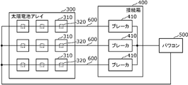
- FIG. 6 is a diagram for explaining an application example of the arc detection device according to the present invention.
- the arc detection device is applied to, for example, each component in a system in which DC power supplied from a solar panel 310 via wiring is converted into AC power by a power conditioner 500.
- a plurality (for example, three) of solar panels 310 connected in series by one wiring 600 (string) are arranged side by side to form a solar cell array 300.
- the plurality of wirings 600 are grouped by the junction box 400 and connected to the power conditioner 500.
- the DC power supply is the solar panel 310
- the first wiring is the wiring 600 connected to the positive electrode of the solar panel 310
- the second wiring is the wiring 600 connected to the negative electrode of the solar panel 310.
- the wiring 600 is branched in the power conditioner 500.
- a breaker 410 is provided for each wiring 600, and here, a breaker 410 is provided in the junction box 400.
- the breaker 410 does not have to be provided in the junction box 400.
- the breaker 410 may be provided between the junction box 400 and the solar cell array 300, or may be provided between the junction box 400 and the power conditioner 500 without being provided for each wiring 600.
- the solar panel 310 has, for example, a solar panel accessory module 320 that converts a signal output from the solar panel 310.
- the solar panel accessory module 320 is, for example, a DC / DC converter that optimizes the amount of power generation for each solar panel 310.
- the solar panel 310 does not have to have the module attached to the solar panel 320.
- the breaker 410 may be provided with an arc detection device.
- the breaker 410 cuts off the current flowing through the wiring 600 when it is determined that an abnormality has occurred.
- the solar panel 310 or the module attached to the solar panel 320 may include an arc detection device.
- the solar panel 310 or the module attached to the solar panel 320 stops the output to the wiring 600 when it is determined that an arc has been generated.
- the junction box 400 may be provided with an arc detection device. When it is determined that an arc has been generated, the junction box 400 cuts off the current flowing through the wiring 600, for example, via a breaker 410 or the like.
- the arc detection device according to the present invention is not limited to these, and can be applied to all systems that require arc detection.
- the breaker 410 may be provided with an arc detection device, and when it is determined that an arc has been generated, the current flowing through the first wiring and the second wiring may be cut off.
- the solar panel 310 may include an arc detection device and generate electricity by sunlight.
- the solar panel accessory module 320 may include an arc detection device and convert the signal output from the solar panel 310.
- the junction box 400 may include an arc detection device and may connect the solar panel 310 and the power conditioner 500.
- the arc determination unit included in the arc detection device may be realized by software in a general-purpose computer such as a personal computer.
Abstract
An arc detection device (10a) includes: a low impedance circuit (11) connected between a node (N1) on wiring (110) and a node (N2) on wiring (120), the wiring (110) connecting a positive electrode of a DC/DC converter (61) to a plurality of DC/DC converters (51, 52 and 53) and branching from the positive electrode of the DC/DC converter (61) to the plurality of DC/DC converters (51, 52 and 53), the wiring (120) connecting a negative electrode of the DC/DC converter (61) to the plurality of DC/DC converters (51, 52 and 53) and branching from the negative electrode of the DC/DC converter (61) to the plurality of DC/DC converters (51, 53 and 53); a current detection unit (20a) for detecting a current flowing in the low impedance circuit (11); and an arc determination unit (30) for determining, on the basis of the current detected by the current detection unit (20a), occurrence of an arc.
Description
本発明は、アーク検出装置、パワーコンディショナ、屋内配線システム、ブレーカ、太陽光パネル、太陽光パネル付属モジュール及び接続箱に関する。
The present invention relates to an arc detection device, a power conditioner, an indoor wiring system, a breaker, a solar panel, a module attached to the solar panel, and a junction box.
従来、PV(Photo Voltaic)パネル(太陽光パネル)等から配線を介して供給される直流電力をインバータ等の機器で交流電力に変換するシステムが知られている。このような配線は、外的要因又は経年劣化等によって損傷又は破断を引き起こすことが報告されている。このような配線の損傷等に起因してアーク(つまりアーク放電)が発生する場合がある。そこで、アークを検出するためのアーク検出手段が提案されている(例えば、特許文献1)。
Conventionally, a system is known in which DC power supplied from a PV (Photo Voltic) panel (solar panel) or the like via wiring is converted into AC power by a device such as an inverter. It has been reported that such wiring causes damage or breakage due to external factors, aging deterioration, or the like. An arc (that is, an arc discharge) may occur due to such damage to the wiring. Therefore, an arc detecting means for detecting an arc has been proposed (for example, Patent Document 1).
今後、1つのシステム内において複数の機器が設けられ、1つの直流電源から複数の機器のそれぞれへと分岐している配線(分岐配線と呼ぶ)を介して複数の機器に電力を供給することが想定される。このとき、分岐配線の分岐前の経路と分岐後の複数の経路のそれぞれについてアークが発生する場合がある。分岐配線の分岐前の経路と分岐後の複数の経路のそれぞれにアーク検出手段を設ければ、分岐前の経路と分岐後の複数の経路のそれぞれについてアークを検出することができるが、システムが大型化し、また、高コスト化する。
In the future, it will be possible to provide multiple devices in one system and supply power to multiple devices via wiring (called branch wiring) that branches from one DC power supply to each of the multiple devices. is assumed. At this time, an arc may be generated for each of the path before branching and the plurality of paths after branching of the branch wiring. If arc detection means are provided for each of the pre-branch route and the post-branch route of the branch wiring, the arc can be detected for each of the pre-branch route and the post-branch route, but the system can detect the arc. The size will increase and the cost will increase.
そこで、本発明は、分岐配線において発生するアークを容易に検出できるアーク検出装置等を提供する。
Therefore, the present invention provides an arc detection device or the like that can easily detect an arc generated in a branch wiring.
本発明に係るアーク検出装置の一態様は、直流電源の正極と複数の機器とを接続し、前記直流電源の正極から前記複数の機器のそれぞれへと分岐している第1配線上の第1ノードと、前記直流電源の負極と前記複数の機器とを接続し前記直流電源の負極から前記複数の機器のそれぞれへと分岐している第2配線上の第2ノードとの間に接続され、前記複数の機器のそれぞれよりもインピーダンスが低い低インピーダンス回路と、前記低インピーダンス回路を流れる電流を検出する電流検出部と、前記電流検出部により検出された電流に基づいて、アークの発生を判定するアーク判定部と、を備える。
One aspect of the arc detection device according to the present invention is a first wiring on a first wiring that connects a positive electrode of a DC power supply and a plurality of devices and branches from the positive electrode of the DC power supply to each of the plurality of devices. The node is connected to the negative electrode of the DC power supply and the plurality of devices, and is connected between the negative electrode of the DC power supply and the second node on the second wiring branching to each of the plurality of devices. The generation of an arc is determined based on a low-impedance circuit having a lower impedance than that of each of the plurality of devices, a current detection unit that detects a current flowing through the low-impedance circuit, and a current detected by the current detection unit. It is provided with an arc determination unit.
本発明に係るパワーコンディショナの一態様は、上記のアーク検出装置と、前記直流電源の出力電力を変換する変換器と、を備える。
One aspect of the power conditioner according to the present invention includes the above arc detection device and a converter that converts the output power of the DC power supply.
本発明に係る屋内配線システムの一態様は、上記のアーク検出装置と、前記第1配線と、前記第2配線と、屋内に設置された前記複数の機器と、を備える。
One aspect of the indoor wiring system according to the present invention includes the arc detection device, the first wiring, the second wiring, and the plurality of devices installed indoors.
本発明に係るブレーカの一態様は、上記のアーク検出装置を備え、アークが発生したと判定された場合に、前記第1配線及び前記第2配線に流れる電流を遮断する。
One aspect of the breaker according to the present invention is provided with the above-mentioned arc detection device, and when it is determined that an arc has been generated, the current flowing through the first wiring and the second wiring is cut off.
本発明に係る太陽光パネルの一態様は、上記のアーク検出装置を備え、太陽光により発電する。
One aspect of the solar panel according to the present invention is provided with the above-mentioned arc detection device and generates electricity by sunlight.
本発明に係る太陽光パネル付属モジュールの一態様は、上記のアーク検出装置を備え、太陽光パネルから出力される信号の変換を行う。
One aspect of the module attached to the solar panel according to the present invention is provided with the above-mentioned arc detection device and converts the signal output from the solar panel.
本発明に係る接続箱の一態様は、上記のアーク検出装置を備え、太陽光パネルとパワーコンディショナとを接続する。
One aspect of the junction box according to the present invention is provided with the above-mentioned arc detection device, and connects the solar panel and the power conditioner.
本発明の一態様によれば、分岐配線において発生するアークを容易に検出できる。
According to one aspect of the present invention, an arc generated in a branch wiring can be easily detected.
以下、本発明の実施の形態について、図面を参照しながら説明する。以下に説明する実施の形態は、いずれも本発明の一具体例を示すものである。したがって、以下の実施の形態で示される数値、形状、材料、構成要素、構成要素の配置位置及び接続形態等は、一例であって本発明を限定する主旨ではない。
Hereinafter, embodiments of the present invention will be described with reference to the drawings. Each of the embodiments described below shows a specific example of the present invention. Therefore, the numerical values, shapes, materials, components, arrangement positions of the components, connection forms, etc. shown in the following embodiments are examples and are not intended to limit the present invention.
なお、各図は、模式図であり、必ずしも厳密に図示されたものではない。また、各図において、実質的に同一の構成に対しては同一の符号を付しており、重複する説明は省略又は簡略化する。
Note that each figure is a schematic view and is not necessarily exactly illustrated. Further, in each figure, substantially the same configuration is designated by the same reference numerals, and duplicate description will be omitted or simplified.
(実施の形態1)
図1は、実施の形態1に係る太陽光発電システム1aの一例を示す構成図である。 (Embodiment 1)
FIG. 1 is a configuration diagram showing an example of a photovoltaicpower generation system 1a according to the first embodiment.
図1は、実施の形態1に係る太陽光発電システム1aの一例を示す構成図である。 (Embodiment 1)
FIG. 1 is a configuration diagram showing an example of a photovoltaic
太陽光発電システム1aは、太陽光パネル41、蓄電池54、55及び56、DC/DCコンバータ51、52及び53並びにパワーコンディショナ(パワコン)60aを備える。
The photovoltaic power generation system 1a includes a solar panel 41, storage batteries 54, 55 and 56, DC / DC converters 51, 52 and 53, and a power conditioner (power conditioner) 60a.
太陽光パネル41は、太陽光により発電し直流電力を発生する。太陽光パネル41で発生した直流電力はパワコン60aに供給される。
The solar panel 41 generates electricity by sunlight and generates DC power. The DC power generated by the solar panel 41 is supplied to the power conditioner 60a.
蓄電池54はDC/DCコンバータ51からの直流電力を蓄電し、蓄電池55はDC/DCコンバータ52からの直流電力を蓄電し、蓄電池56はDC/DCコンバータ53からの直流電力を蓄電する。例えば、蓄電池54、55及び56は、電気自動車又は電動自転車等に搭載されてもよいし、家庭用電気機器等への電力供給のために用いられてもよい。
The storage battery 54 stores the DC power from the DC / DC converter 51, the storage battery 55 stores the DC power from the DC / DC converter 52, and the storage battery 56 stores the DC power from the DC / DC converter 53. For example, the storage batteries 54, 55, and 56 may be mounted on an electric vehicle, an electric bicycle, or the like, or may be used for supplying power to household electric appliances or the like.
DC/DCコンバータ51、52及び53は、供給された直流電力の直流電圧を昇圧又は降圧して出力する電圧変換器である。DC/DCコンバータ51は、パワコン60aから供給された直流電力を昇圧又は降圧して、蓄電池54に出力する。DC/DCコンバータ52は、パワコン60aから供給された直流電力を昇圧又は降圧して、蓄電池55に出力する。DC/DCコンバータ53は、パワコン60aから供給された直流電力を昇圧又は降圧して、蓄電池56に出力する。
The DC / DC converters 51, 52, and 53 are voltage converters that boost or step down the DC voltage of the supplied DC power and output it. The DC / DC converter 51 boosts or lowers the DC power supplied from the power conditioner 60a and outputs it to the storage battery 54. The DC / DC converter 52 boosts or lowers the DC power supplied from the power conditioner 60a and outputs it to the storage battery 55. The DC / DC converter 53 boosts or lowers the DC power supplied from the power conditioner 60a and outputs it to the storage battery 56.
パワコン60aは、太陽光パネル41から供給される直流電力を交流電力に変換する機能を有する。また、パワコン60aは、太陽光パネル41から供給される直流電力を交流電力に変換せずに蓄電池等に供給する機能を有する。パワコン60aは、DC/DCコンバータ61、インバータ62及びアーク検出装置10aを備える。
The power conditioner 60a has a function of converting DC power supplied from the solar panel 41 into AC power. Further, the power conditioner 60a has a function of supplying DC power supplied from the solar panel 41 to a storage battery or the like without converting it into AC power. The power conditioner 60a includes a DC / DC converter 61, an inverter 62, and an arc detection device 10a.
DC/DCコンバータ61は、太陽光パネル41から供給された直流電力を昇圧又は降圧して、DC/DCコンバータ51、52及び53並びにインバータ62へ出力する。DC/DCコンバータ61からは直流電力が出力されるため、DC/DCコンバータ61は直流電源とみなすことができる。すなわち、DC/DCコンバータ61は、直流電源の一例である。DC/DCコンバータ61は正極と負極を有し、正極には配線110が接続され、負極には配線120が接続される。
The DC / DC converter 61 boosts or lowers the DC power supplied from the solar panel 41 and outputs it to the DC / DC converters 51, 52 and 53 and the inverter 62. Since DC power is output from the DC / DC converter 61, the DC / DC converter 61 can be regarded as a DC power supply. That is, the DC / DC converter 61 is an example of a DC power supply. The DC / DC converter 61 has a positive electrode and a negative electrode, and the wiring 110 is connected to the positive electrode and the wiring 120 is connected to the negative electrode.
配線110及び120は、DC/DCコンバータ61とDC/DCコンバータ51、52及び53とを接続する。配線110は、DC/DCコンバータ61の正極と複数の機器とを接続する第1配線の一例である。配線120は、DC/DCコンバータ61の負極と複数の機器とを接続する第2配線の一例である。DC/DCコンバータ51、52及び53は、配線110及び120を介してDC/DCコンバータ61に接続される複数の機器の一例である。
Wiring 110 and 120 connect the DC / DC converter 61 and the DC / DC converters 51, 52 and 53. The wiring 110 is an example of the first wiring for connecting the positive electrode of the DC / DC converter 61 and a plurality of devices. The wiring 120 is an example of the second wiring that connects the negative electrode of the DC / DC converter 61 and a plurality of devices. The DC / DC converters 51, 52 and 53 are examples of a plurality of devices connected to the DC / DC converter 61 via the wirings 110 and 120.
配線110は、DC/DCコンバータ61の正極からDC/DCコンバータ51、52及び53のそれぞれへと分岐している配線である。配線110におけるDC/DCコンバータ61の正極からDC/DCコンバータ51、52及び53へ分岐する点を分岐点N3とする。
The wiring 110 is wiring that branches from the positive electrode of the DC / DC converter 61 to each of the DC / DC converters 51, 52, and 53. The point at which the positive electrode of the DC / DC converter 61 in the wiring 110 branches to the DC / DC converters 51, 52, and 53 is defined as the branch point N3.
配線110において、分岐点N3とDC/DCコンバータ61の正極とを結ぶ分岐前の経路である第1分岐前経路を経路110aとする。
In the wiring 110, the first pre-branch route, which is the pre-branch route connecting the branch point N3 and the positive electrode of the DC / DC converter 61, is set as the route 110a.
配線110は、分岐点N3とDC/DCコンバータ51、52及び53のそれぞれとを結ぶ複数の第1分岐後経路を有する。配線110において、分岐点N3とDC/DCコンバータ51とを結ぶ第1分岐後経路を経路110cとし、分岐点N3とDC/DCコンバータ52とを結ぶ第1分岐後経路を経路110dとし、分岐点N3とDC/DCコンバータ53とを結ぶ第1分岐後経路を経路110bとする。
The wiring 110 has a plurality of first post-branch paths connecting the branch point N3 and each of the DC / DC converters 51, 52, and 53. In the wiring 110, the first post-branch path connecting the branch point N3 and the DC / DC converter 51 is set as the path 110c, and the first post-branch path connecting the branch point N3 and the DC / DC converter 52 is set as the path 110d, and the branch point is set. The path after the first branch connecting N3 and the DC / DC converter 53 is defined as the path 110b.
配線120は、DC/DCコンバータ61の負極からDC/DCコンバータ51、52及び53のそれぞれへと分岐している配線である。配線120におけるDC/DCコンバータ61の負極からDC/DCコンバータ51、52及び53へ分岐する点を分岐点N4とする。
The wiring 120 is a wiring that branches from the negative electrode of the DC / DC converter 61 to each of the DC / DC converters 51, 52, and 53. The point at which the negative electrode of the DC / DC converter 61 in the wiring 120 branches to the DC / DC converters 51, 52, and 53 is defined as the branch point N4.
配線120において、分岐点N4とDC/DCコンバータ61の負極とを結ぶ分岐前の経路である第2分岐前経路を経路120aとする。
In the wiring 120, the second pre-branch path, which is the pre-branch path connecting the branch point N4 and the negative electrode of the DC / DC converter 61, is set as the path 120a.
配線120は、分岐点N4とDC/DCコンバータ51、52及び53のそれぞれとを結ぶ複数の第2分岐後経路を有する。配線120において、分岐点N4とDC/DCコンバータ51とを結ぶ第2分岐後経路を経路120cとし、分岐点N4とDC/DCコンバータ52とを結ぶ第2分岐後経路を経路120dとし、分岐点N4とDC/DCコンバータ53とを結ぶ第2分岐後経路を経路120bとする。
The wiring 120 has a plurality of second post-branch paths connecting the branch point N4 and each of the DC / DC converters 51, 52, and 53. In the wiring 120, the second post-branch path connecting the branch point N4 and the DC / DC converter 51 is the path 120c, and the second post-branch path connecting the branch point N4 and the DC / DC converter 52 is the path 120d, and the branch point. The path 120b is the path after the second branch connecting N4 and the DC / DC converter 53.
インバータ62は、DC/DCコンバータ61から供給された直流電力を交流電力に変換して出力する。インバータ62は、例えばMPPT(Maximum Power Point Tracking)方式を採用しており、DC/DCコンバータ61から供給される直流電力の電流及び電圧を、それぞれ電力が最大となる値に調整する。例えば、インバータ62は、直流電力を電圧100V、周波数50Hz又は60Hzの交流電力に変換する。当該交流電力は、家庭用電気機器等で使用される。
The inverter 62 converts the DC power supplied from the DC / DC converter 61 into AC power and outputs it. The inverter 62 employs, for example, an MPPT (Maximum Power Point Tracking) method, and adjusts the current and voltage of the DC power supplied from the DC / DC converter 61 to values that maximize the power, respectively. For example, the inverter 62 converts DC power into AC power having a voltage of 100 V and a frequency of 50 Hz or 60 Hz. The AC power is used in household electric appliances and the like.
配線110及び120は分岐配線であり、分岐配線の分岐前の経路と分岐後の複数の経路のそれぞれについてアークが発生する場合がある。分岐前の経路と分岐後の複数の経路のそれぞれにアーク検出手段を設ければ、分岐前の経路と分岐後の複数の経路のそれぞれについてアークを検出することができるが、システムが大型化し、また、高コスト化する。
Wiring 110 and 120 are branch wirings, and arcs may be generated for each of the pre-branch path and the post-branch plurality of paths of the branch wiring. If arc detection means are provided for each of the pre-branch route and the plurality of post-branch routes, arcs can be detected for each of the pre-branch route and the post-branch route, but the system becomes large and the system becomes large. In addition, the cost will be increased.
そこで、分岐配線(ここでは配線110及び120)において発生するアークを容易に検出するために、アーク検出装置10aが用いられる。
Therefore, in order to easily detect the arc generated in the branch wiring (here, wirings 110 and 120), the arc detection device 10a is used.
アーク検出装置10aは、低インピーダンス回路11、電流検出部20a及びアーク判定部30を備える。
The arc detection device 10a includes a low impedance circuit 11, a current detection unit 20a, and an arc determination unit 30.
低インピーダンス回路11は、配線110上のノードN1と、配線120上のノードN2との間に接続される回路である。ノードN1は第1ノードの一例であり、ノードN2は第2ノードの一例である。低インピーダンス回路11は、例えばコンデンサである。コンデンサは、直流成分を遮断する機能を有するため、配線110及び120を流れる信号から高周波成分のみを抽出することができる。コンデンサのキャパシタンス値は、抽出したい高周波成分の周波数等に応じて適宜決定される。低インピーダンス回路11は、DC/DCコンバータ51、52、53のそれぞれよりもインピーダンスが低い。また、低インピーダンス回路11は、DC/DCコンバータ61よりもインピーダンスが低い。これにより、配線110及び120では、低インピーダンス回路11へ向けて高周波成分が流れやすくなっている。詳細については、図2Aから図2Cを用いて後述する。
The low impedance circuit 11 is a circuit connected between the node N1 on the wiring 110 and the node N2 on the wiring 120. Node N1 is an example of the first node, and node N2 is an example of the second node. The low impedance circuit 11 is, for example, a capacitor. Since the capacitor has a function of blocking the DC component, only the high frequency component can be extracted from the signals flowing through the wirings 110 and 120. The capacitance value of the capacitor is appropriately determined according to the frequency of the high frequency component to be extracted and the like. The low impedance circuit 11 has a lower impedance than each of the DC / DC converters 51, 52, and 53. Further, the low impedance circuit 11 has a lower impedance than the DC / DC converter 61. As a result, in the wirings 110 and 120, the high frequency component easily flows toward the low impedance circuit 11. Details will be described later with reference to FIGS. 2A to 2C.
電流検出部20aは、低インピーダンス回路11を流れる電流を検出する。例えば、電流検出部20aは、ノードN1とノードN2とを結ぶ経路に流れる電流を検出することにより、低インピーダンス回路11を流れる電流を検出する。例えば、電流検出部20aは、ノードN1とノードN2とを結ぶ経路が貫通する磁気コア21を有し、磁気コア21に発生する磁界に応じて当該経路を流れる電流(すなわち低インピーダンス回路11を流れる電流)を検出する。
The current detection unit 20a detects the current flowing through the low impedance circuit 11. For example, the current detection unit 20a detects the current flowing through the low impedance circuit 11 by detecting the current flowing in the path connecting the node N1 and the node N2. For example, the current detection unit 20a has a magnetic core 21 through which a path connecting the node N1 and the node N2 penetrates, and flows a current flowing through the path (that is, a low impedance circuit 11) according to a magnetic field generated in the magnetic core 21. Current) is detected.
磁気コア21は、配線が貫通可能な環状形状(ここでは円環形状)となっており、自身の孔を貫通する配線に流れる電流によって、当該電流に応じた磁界がコアに発生する。なお、磁気コア21は、円環形状に限らず、矩形状の環状形状等であってもよい。
The magnetic core 21 has an annular shape (here, an annular shape) through which wiring can penetrate, and a magnetic field corresponding to the current is generated in the core by the current flowing through the wiring penetrating its own hole. The magnetic core 21 is not limited to an annular shape, but may have a rectangular annular shape or the like.
また、電流検出部20aは、例えば、磁気コア21に発生する磁界を検出して、磁気コア21に発生する磁界に応じた電圧を発生するホール素子(図示せず)を備える。ホール素子が発生する電圧は、磁気コア21に発生した磁界、つまり、磁気コア21を貫通する経路を流れる電流を示す信号としてアーク判定部30に入力される。
Further, the current detection unit 20a includes, for example, a Hall element (not shown) that detects a magnetic field generated in the magnetic core 21 and generates a voltage corresponding to the magnetic field generated in the magnetic core 21. The voltage generated by the Hall element is input to the arc determination unit 30 as a signal indicating a magnetic field generated in the magnetic core 21, that is, a current flowing through a path passing through the magnetic core 21.
アーク判定部30は、例えばマイコン(マイクロコントローラ)により実現される。マイコンは、プログラムが格納されたROM、RAM、プログラムを実行するプロセッサ(CPU:Central Processing Unit)、タイマ、A/D変換器及びD/A変換器等を有する半導体集積回路等である。なお、アーク判定部30は、A/D変換器、論理回路、ゲートアレイ及びD/A変換器等で構成される専用の電子回路によってハードウェア的に実現されてもよい。
The arc determination unit 30 is realized by, for example, a microcomputer (microcontroller). The microcomputer is a ROM, a RAM in which a program is stored, a processor (CPU: Central Processing Unit) for executing a program, a timer, an A / D converter, a semiconductor integrated circuit having a D / A converter, and the like. The arc determination unit 30 may be realized by hardware by a dedicated electronic circuit composed of an A / D converter, a logic circuit, a gate array, a D / A converter, and the like.
アーク判定部30は、電流検出部20aにより検出された電流に基づいて、アークの発生を判定する。例えば、アーク判定部30は、電流検出部20aにより検出された電流を周波数分析することで配線110又は120におけるアークの発生を判定する。アークの発生により生じる高周波成分が重畳した電流には、アークに起因する周波数成分が含まれており、当該周波数成分を検出することでアークの発生を判定することができる。アーク判定部30がアークが発生したと判定した場合、配線110及び120のどこかにアークが発生したことがわかる。つまり、1つの電流検出部20a(例えば磁気コア21)のみで、分岐配線(ここでは配線110及び120)におけるアークの発生を検出できる。
The arc determination unit 30 determines the generation of an arc based on the current detected by the current detection unit 20a. For example, the arc determination unit 30 determines the generation of an arc in the wiring 110 or 120 by frequency-analyzing the current detected by the current detection unit 20a. The current on which the high frequency component generated by the generation of the arc is superimposed contains the frequency component caused by the arc, and the generation of the arc can be determined by detecting the frequency component. When the arc determination unit 30 determines that an arc has occurred, it can be seen that an arc has occurred somewhere in the wirings 110 and 120. That is, the generation of an arc in the branch wiring (here, the wirings 110 and 120) can be detected by only one current detection unit 20a (for example, the magnetic core 21).
例えば、配線110における点A1でアークが発生したときに、アークの発生により生じる高周波成分が低インピーダンス回路11へ向けて流れやすくなっていることを図2Aから図2Cを用いて説明する。
For example, it will be described with reference to FIGS. 2A to 2C that when an arc is generated at the point A1 in the wiring 110, the high frequency component generated by the generation of the arc easily flows toward the low impedance circuit 11.
図2Aは、点A1でアークが発生したときの点A1を流れる電流の周波数スペクトルを示す図である。点A1は、経路110c上の点である。具体的には、点A1は、経路110cにおけるパワコン60aとDC/DCコンバータ51とを結ぶ経路上の点である。
FIG. 2A is a diagram showing a frequency spectrum of a current flowing through the point A1 when an arc is generated at the point A1. Point A1 is a point on the path 110c. Specifically, the point A1 is a point on the path connecting the power conditioner 60a and the DC / DC converter 51 in the path 110c.
図2Bは、点A1でアークが発生したときの点A2を流れる電流の周波数スペクトルを示す図である。点A2は、ノードN1とノードN2とを結ぶ経路上の点である。すなわち、点A2を流れる電流は、低インピーダンス回路11を流れる電流となる。
FIG. 2B is a diagram showing a frequency spectrum of a current flowing through the point A2 when an arc is generated at the point A1. Point A2 is a point on the path connecting node N1 and node N2. That is, the current flowing through the point A2 is the current flowing through the low impedance circuit 11.
図2Cは、点A1でアークが発生したときの点A3及びA4を流れる電流の周波数スペクトルを示す図である。点A3は、経路110d上の点であり、点A4は、経路110b上の点である。
FIG. 2C is a diagram showing a frequency spectrum of currents flowing through points A3 and A4 when an arc is generated at point A1. The point A3 is a point on the path 110d, and the point A4 is a point on the path 110b.
点A1においてアークが発生したため、点A1では、図2Aに示されるようなアークの発生により生じる高周波成分が重畳した電流の周波数スペクトルが計測される。
Since the arc was generated at the point A1, the frequency spectrum of the current on which the high frequency component generated by the generation of the arc as shown in FIG. 2A is superimposed is measured at the point A1.
図2Bに示されるように、点A2でも、図2Aに示されるようなアークの発生により生じる高周波成分が重畳した電流の周波数スペクトルと同じような周波数スペクトルが計測される。これは、点A1で発生したアークによる高周波成分が分岐点N3において経路110aへ向かい、ノードN1において低インピーダンス回路11へ向かうためである。
As shown in FIG. 2B, at point A2, a frequency spectrum similar to the frequency spectrum of the current on which the high frequency component generated by the generation of the arc as shown in FIG. 2A is superimposed is measured. This is because the high frequency component due to the arc generated at the point A1 heads toward the path 110a at the branch point N3 and heads toward the low impedance circuit 11 at the node N1.
一方で、図2Cに示されるように、点A3及びA4では、図2Aに示されるようなアークの発生により生じる高周波成分が重畳した電流の周波数スペクトルが計測されない。これは、DC/DCコンバータ52及び53のインピーダンスが低インピーダンス回路11のインピーダンスよりも高く、分岐点N3において高周波成分が経路110d及び110bに流れにくくなっているためである。
On the other hand, as shown in FIG. 2C, at points A3 and A4, the frequency spectrum of the current on which the high frequency component generated by the generation of the arc as shown in FIG. 2A is superimposed is not measured. This is because the impedance of the DC / DC converters 52 and 53 is higher than the impedance of the low impedance circuit 11, and the high frequency component is less likely to flow in the paths 110d and 110b at the branch point N3.
このように、点A1で発生したアークにより生じる高周波成分がインピーダンスの低い低インピーダンス回路11へ向けて流れ、インピーダンスの高いDC/DCコンバータ52、53及び61へは流れにくくなっていることがわかる。
As described above, it can be seen that the high frequency component generated by the arc generated at the point A1 flows toward the low impedance circuit 11 having a low impedance, and is difficult to flow to the DC / DC converters 52, 53 and 61 having a high impedance.
例えば、他の分岐後経路でアークが発生した場合であっても、アークの発生により生じる高周波成分は、インピーダンスの高いDC/DCコンバータへは流れにくく、インピーダンスの低い低インピーダンス回路11へ向けて流れやすくなっている。
For example, even when an arc is generated in another post-branch path, the high-frequency component generated by the generation of the arc is difficult to flow to the DC / DC converter having high impedance, and flows to the low impedance circuit 11 having low impedance. It's getting easier.
なお、ノードN1が経路110a上のノードであり、ノードN2が経路110b上のノードである例について説明したが、実施の形態1では、ノードN1は、経路110b、110c又は110d上のノードであってもよく、ノードN2は、経路120b、120c又は120d上のノードであってもよい。
An example in which the node N1 is a node on the route 110a and the node N2 is a node on the route 110b has been described. However, in the first embodiment, the node N1 is a node on the route 110b, 110c or 110d. The node N2 may be a node on the path 120b, 120c or 120d.
以上説明したように、本実施の形態に係るアーク検出装置10aは、直流電源(例えばDC/DCコンバータ61)の正極と複数の機器(例えばDC/DCコンバータ51、52及び53)とを接続し、直流電源の正極から複数の機器のそれぞれへと分岐している第1配線(例えば配線110)上の第1ノード(例えばノードN1)と、直流電源の負極と複数の機器とを接続し直流電源の負極から複数の機器のそれぞれへと分岐している第2配線(例えば配線120)上の第2ノード(例えばノードN2)との間に接続され、複数の機器のそれぞれよりもインピーダンスが低い低インピーダンス回路11と、低インピーダンス回路11を流れる電流を検出する電流検出部20aと、電流検出部20aにより検出された電流に基づいて、アークの発生を判定するアーク判定部30と、を備える。
As described above, the arc detection device 10a according to the present embodiment connects the positive electrode of the DC power supply (for example, DC / DC converter 61) and a plurality of devices (for example, DC / DC converters 51, 52, 53). , The first node (for example, node N1) on the first wiring (for example, wiring 110) branching from the positive side of the DC power supply to each of the plurality of devices, and the negative side of the DC power supply and the plurality of devices are connected to DC. It is connected between the negative side of the power supply and the second node (for example, node N2) on the second wiring (for example, wiring 120) that branches to each of the plurality of devices, and has a lower impedance than each of the plurality of devices. It includes a low-impedance circuit 11, a current detection unit 20a that detects the current flowing through the low-impedance circuit 11, and an arc determination unit 30 that determines the generation of an arc based on the current detected by the current detection unit 20a.
これによれば、第1配線及び第2配線の分岐前の経路と分岐後の複数の経路のそれぞれ(例えば、経路110a、110b、110c、110d、120a、120b、120c及び120d)のどこでアークが発生したとしても、アークの発生により生じる高周波成分は、複数の機器のそれぞれよりもインピーダンスが低い低インピーダンス回路11へ向けて流れる。このため、低インピーダンス回路11を流れる電流を検出する電流検出部20aにより検出された電流に基づいてアークを検出できる。つまり、分岐配線の分岐前の経路と分岐後の複数の経路のそれぞれにアーク検出手段を設けなくても、分岐配線において発生するアークを検出できる。すなわち、システムを大型化したり、高コスト化したりしなくてもよく、1つの電流検出部20aを用いて、分岐配線において発生するアークを容易に検出できる。例えば、アークの検出された場合、当該検出結果に基づいて、DC/DCコンバータ61及びインバータ62を停止したり、各配線に設けられたブレーカ等(図示せず)を操作したりして、各配線を流れる電流を遮断することができる。
According to this, where in each of the pre-branch route and the plurality of post-branch routes (for example, routes 110a, 110b, 110c, 110d, 120a, 120b, 120c and 120d) of the first wiring and the second wiring, the arc is generated. Even if it is generated, the high frequency component generated by the generation of the arc flows toward the low impedance circuit 11 whose impedance is lower than that of each of the plurality of devices. Therefore, the arc can be detected based on the current detected by the current detection unit 20a that detects the current flowing through the low impedance circuit 11. That is, it is possible to detect an arc generated in the branch wiring without providing arc detection means for each of the path before branching and the plurality of paths after branching of the branch wiring. That is, it is not necessary to increase the size or cost of the system, and the arc generated in the branch wiring can be easily detected by using one current detection unit 20a. For example, when an arc is detected, the DC / DC converter 61 and the inverter 62 are stopped or a breaker or the like (not shown) provided in each wiring is operated based on the detection result. The current flowing through the wiring can be cut off.
例えば、電流検出部20aは、第1ノードと第2ノードとを結ぶ経路に流れる電流を検出することにより、低インピーダンス回路11を流れる電流を検出してもよい。
For example, the current detection unit 20a may detect the current flowing through the low impedance circuit 11 by detecting the current flowing through the path connecting the first node and the second node.
これによれば、電流検出部20aは、第1ノードと第2ノードとを結ぶ経路に設けられた低インピーダンス回路11を流れる電流を検出しやすくなる。
According to this, the current detection unit 20a can easily detect the current flowing through the low impedance circuit 11 provided in the path connecting the first node and the second node.
本実施の形態に係るパワコン60aは、アーク検出装置10aと、直流電源の出力電力を変換する変換器(例えばインバータ62)と、を備える。
The power conditioner 60a according to the present embodiment includes an arc detection device 10a and a converter (for example, an inverter 62) that converts the output power of the DC power supply.
これによれば、分岐配線において発生するアークを容易に検出できるパワコン60aを提供できる。
According to this, it is possible to provide a power conditioner 60a that can easily detect an arc generated in a branch wiring.
(実施の形態1の変形例1)
実施の形態1の変形例1では、電流検出部が分岐前経路である経路110a又は120aを流れる電流を検出する例について説明する。 (Modification 1 of Embodiment 1)
In the first modification of the first embodiment, an example in which the current detection unit detects the current flowing through the path 110a or 120a, which is the pre-branch path, will be described.
実施の形態1の変形例1では、電流検出部が分岐前経路である経路110a又は120aを流れる電流を検出する例について説明する。 (Modification 1 of Embodiment 1)
In the first modification of the first embodiment, an example in which the current detection unit detects the current flowing through the
図3は、実施の形態1の変形例1に係る太陽光発電システム1bの一例を示す構成図である。
FIG. 3 is a configuration diagram showing an example of the photovoltaic power generation system 1b according to the first modification of the first embodiment.
太陽光発電システム1bは、パワコン60aの代わりにパワコン60bを備える点が、実施の形態1に係る太陽光発電システム1aと異なる。その他の点については、実施の形態1におけるものと同じであるため、説明は省略する。
The photovoltaic power generation system 1b is different from the photovoltaic power generation system 1a according to the first embodiment in that the power conditioner 60b is provided instead of the power conditioner 60a. Since other points are the same as those in the first embodiment, the description thereof will be omitted.
パワコン60bは、太陽光パネル41から供給される直流電力を交流電力に変換する機能を有する。また、パワコン60bは、太陽光パネル41から供給される直流電力を交流電力に変換せずに蓄電池等に供給する機能を有する。パワコン60bは、アーク検出装置10aの代わりにアーク検出装置10bを備える点が、実施の形態1に係るパワコン60aと異なる。その他の点については、実施の形態1におけるものと同じであるため、説明は省略する。
The power conditioner 60b has a function of converting DC power supplied from the solar panel 41 into AC power. Further, the power conditioner 60b has a function of supplying DC power supplied from the solar panel 41 to a storage battery or the like without converting it into AC power. The power conditioner 60b is different from the power conditioner 60a according to the first embodiment in that the arc detection device 10b is provided instead of the arc detection device 10a. Since other points are the same as those in the first embodiment, the description thereof will be omitted.
アーク検出装置10bは、低インピーダンス回路11、電流検出部20b及びアーク判定部30を備える。低インピーダンス回路11及びアーク判定部30については、実施の形態1におけるものに対応しているため、説明は省略する。
The arc detection device 10b includes a low impedance circuit 11, a current detection unit 20b, and an arc determination unit 30. Since the low impedance circuit 11 and the arc determination unit 30 correspond to those in the first embodiment, the description thereof will be omitted.
電流検出部20bは、低インピーダンス回路11を流れる電流を検出する。例えば、電流検出部20bは、経路110a又は110bを流れる電流を検出することにより、低インピーダンス回路11を流れる電流を検出する。具体的には、電流検出部20bは、経路110aにおけるノードN1と分岐点N3とを結ぶ経路又は経路110bにおけるノードN2と分岐点N4とを結ぶ経路を流れる電流を検出する。ここでは、例えば、電流検出部20bは、経路110a(具体的には、経路110aにおけるノードN1と分岐点N3とを結ぶ経路)が貫通する磁気コア21を有し、磁気コア21に発生する磁界に応じて当該経路を流れる電流(すなわち低インピーダンス回路11を流れる電流)を検出する。
The current detection unit 20b detects the current flowing through the low impedance circuit 11. For example, the current detection unit 20b detects the current flowing through the low impedance circuit 11 by detecting the current flowing through the path 110a or 110b. Specifically, the current detection unit 20b detects the current flowing through the path connecting the node N1 and the branch point N3 in the path 110a or the path connecting the node N2 and the branch point N4 in the path 110b. Here, for example, the current detection unit 20b has a magnetic core 21 through which the path 110a (specifically, the path connecting the node N1 and the branch point N3 in the path 110a) penetrates, and the magnetic field generated in the magnetic core 21. The current flowing through the path (that is, the current flowing through the low impedance circuit 11) is detected accordingly.
例えば、配線110における点B1でアークが発生したときに、アークの発生により生じる高周波成分が低インピーダンス回路11へ向けて流れやすくなっており、経路110aを流れる電流を検出することでアークを検出できることを図2Aから図2Cを用いて説明する。なお、図2Aから図2Cにおける点A1は点B1に、点A2は点B2に、点A3は点B3に、点A4は点B4に読み替えることができる。
For example, when an arc is generated at the point B1 in the wiring 110, the high frequency component generated by the generation of the arc easily flows toward the low impedance circuit 11, and the arc can be detected by detecting the current flowing through the path 110a. 2A to 2C will be described. It should be noted that the point A1 in FIGS. 2A to 2C can be read as a point B1, a point A2 as a point B2, a point A3 as a point B3, and a point A4 as a point B4.
点B1は、経路110c上の点である。具体的には、点B1は、経路110cにおけるパワコン60bとDC/DCコンバータ51とを結ぶ経路上の点である。点B2は、経路110aにおけるノードN1と分岐点N3とを結ぶ経路上の点である。点B3は、経路110d上の点であり、点B4は、経路110b上の点である。
Point B1 is a point on the route 110c. Specifically, the point B1 is a point on the path connecting the power conditioner 60b and the DC / DC converter 51 in the path 110c. The point B2 is a point on the path connecting the node N1 and the branch point N3 in the path 110a. The point B3 is a point on the path 110d, and the point B4 is a point on the path 110b.
点B1においてアークが発生したため、点B1では、図2Aに示されるようなアークの発生により生じる高周波成分が重畳した電流の周波数スペクトルが計測される。
Since the arc was generated at the point B1, the frequency spectrum of the current on which the high frequency component generated by the generation of the arc as shown in FIG. 2A is superimposed is measured at the point B1.
図2Bに示されるように、点B2でも、図2Aに示されるようなアークの発生により生じる高周波成分が重畳した電流の周波数スペクトルと同じような周波数スペクトルが計測される。これは、点B1で発生したアークによる高周波成分が分岐点N3において経路110aへ向かい、点B2を通過し、ノードN1において低インピーダンス回路11へ向かうためである。
As shown in FIG. 2B, at point B2, a frequency spectrum similar to the frequency spectrum of the current on which the high frequency component generated by the generation of the arc as shown in FIG. 2A is superimposed is measured. This is because the high frequency component due to the arc generated at the point B1 heads for the path 110a at the branch point N3, passes through the point B2, and heads for the low impedance circuit 11 at the node N1.
一方で、図2Cに示されるように、点B3及びB4では、図2Aに示されるようなアークの発生により生じる高周波成分が重畳した電流の周波数スペクトルが計測されない。これは、DC/DCコンバータ52及び53のインピーダンスが低インピーダンス回路11のインピーダンスよりも高く、分岐点N3において高周波成分が経路110d及び110bに流れにくくなっているためである。
On the other hand, as shown in FIG. 2C, at points B3 and B4, the frequency spectrum of the current on which the high frequency component generated by the generation of the arc as shown in FIG. 2A is superimposed is not measured. This is because the impedance of the DC / DC converters 52 and 53 is higher than the impedance of the low impedance circuit 11, and the high frequency component is less likely to flow in the paths 110d and 110b at the branch point N3.
このように、点B1で発生したアークにより生じる高周波成分がインピーダンスの低い低インピーダンス回路11へ向けて流れ、インピーダンスの高いDC/DCコンバータ52、53及び61へは流れにくくなっていることがわかる。また、経路110a(具体的には、経路110aにおけるノードN1と分岐点N3とを結ぶ経路)を流れる電流を検出することでアークを検出できることがわかる。
As described above, it can be seen that the high frequency component generated by the arc generated at the point B1 flows toward the low impedance circuit 11 having a low impedance, and is difficult to flow to the DC / DC converters 52, 53 and 61 having a high impedance. Further, it can be seen that the arc can be detected by detecting the current flowing through the path 110a (specifically, the path connecting the node N1 and the branch point N3 in the path 110a).
例えば、他の分岐後経路でアークが発生した場合であっても、アークの発生により生じる高周波成分は、インピーダンスの高いDC/DCコンバータへは流れにくく、インピーダンスの低い低インピーダンス回路11へ向けて流れやすくなっている。
For example, even when an arc is generated in another post-branch path, the high-frequency component generated by the generation of the arc is difficult to flow to the DC / DC converter having high impedance, and flows to the low impedance circuit 11 having low impedance. It's getting easier.
実施の形態1の変形例1では、経路110aにおけるノードN1と分岐点N3とを結ぶ経路、経路110b、110c若しくは110d、又は、経路120aにおけるノードN2と分岐点N4とを結ぶ経路、経路120b、120c若しくは120dにおいて発生するアークを検出できる。
In the first modification of the first embodiment, the route connecting the node N1 and the branch point N3 in the route 110a, the route 110b, 110c or 110d, or the route connecting the node N2 and the branch point N4 in the route 120a, the route 120b, The arc generated at 120c or 120d can be detected.
実施の形態1では、ノードN1は、経路110b、110c又は110d上のノードであってもよく、ノードN2は、経路120b、120c又は120d上のノードであってもよいと説明したが、実施の形態1の変形例1では、ノードN1は、経路110a上のノードであり、ノードN2は、経路120a上のノードであることを要する。高周波成分が、電流検出部20bによる電流の検出が行われる経路110a又は経路120aを流れるようにするためである。
In the first embodiment, it has been described that the node N1 may be a node on the route 110b, 110c or 110d, and the node N2 may be a node on the route 120b, 120c or 120d. In the first modification of the first embodiment, the node N1 is required to be a node on the route 110a, and the node N2 is required to be a node on the route 120a. This is to allow the high frequency component to flow through the path 110a or the path 120a where the current is detected by the current detection unit 20b.
以上説明したように、第1ノード(例えばノードN1)は、第1配線(例えば配線110)における直流電源(例えばDC/DCコンバータ61)の正極から複数の機器(例えばDC/DCコンバータ51、52及び53)のそれぞれへの分岐点N3と直流電源の正極とを結ぶ第1分岐前経路(例えば経路110a)上のノードである。第2ノード(例えばノードN2)は、第2配線(例えば配線120)における直流電源の負極から複数の機器のそれぞれへの分岐点N4と直流電源の負極とを結ぶ第2分岐前経路(例えば経路120a)上のノードである。電流検出部20bは、第1分岐前経路又は第2分岐前経路を流れる電流を検出することにより、低インピーダンス回路11を流れる電流を検出する。
As described above, the first node (for example, node N1) has a plurality of devices (for example, DC / DC converters 51 and 52) from the positive electrode of the DC power supply (for example, DC / DC converter 61) in the first wiring (for example, wiring 110). And 53) are nodes on the first pre-branch path (for example, path 110a) connecting the branch point N3 to each of them and the positive electrode of the DC power supply. The second node (for example, node N2) is a second pre-branch path (for example, a path) connecting the branch point N4 from the negative electrode of the DC power supply to each of the plurality of devices in the second wiring (for example, wiring 120) and the negative electrode of the DC power supply. 120a) The upper node. The current detection unit 20b detects the current flowing through the low impedance circuit 11 by detecting the current flowing through the first pre-branch path or the second pre-branch path.
このように、電流検出部20bは、第1分岐前経路又は第2分岐前経路を流れる電流を検出することにより、低インピーダンス回路11を流れる電流を検出してもよい。
In this way, the current detection unit 20b may detect the current flowing through the low impedance circuit 11 by detecting the current flowing through the first pre-branch path or the second pre-branch path.
(実施の形態1の変形例2)
実施の形態1の変形例2では、電流検出部が分岐後経路である経路110b、110c、110d、120b、120c又は120dを流れる電流を検出する例について説明する。 (Modification 2 of Embodiment 1)
In the second modification of the first embodiment, an example in which the current detection unit detects the current flowing through the paths 110b, 110c, 110d, 120b, 120c or 120d, which are the paths after branching, will be described.
実施の形態1の変形例2では、電流検出部が分岐後経路である経路110b、110c、110d、120b、120c又は120dを流れる電流を検出する例について説明する。 (Modification 2 of Embodiment 1)
In the second modification of the first embodiment, an example in which the current detection unit detects the current flowing through the
図4は、実施の形態1の変形例2に係る太陽光発電システム1cの一例を示す構成図である。
FIG. 4 is a configuration diagram showing an example of the photovoltaic power generation system 1c according to the second modification of the first embodiment.
太陽光発電システム1bは、パワコン60aの代わりにパワコン60cを備える点が、実施の形態1に係る太陽光発電システム1aと異なる。その他の点については、実施の形態1におけるものと同じであるため、説明は省略する。
The photovoltaic power generation system 1b is different from the photovoltaic power generation system 1a according to the first embodiment in that the power conditioner 60c is provided instead of the power conditioner 60a. Since other points are the same as those in the first embodiment, the description thereof will be omitted.
パワコン60cは、太陽光パネル41から供給される直流電力を交流電力に変換する機能を有する。また、パワコン60cは、太陽光パネル41から供給される直流電力を交流電力に変換せずに蓄電池等に供給する機能を有する。パワコン60cは、アーク検出装置10aの代わりにアーク検出装置10cを備える点が、実施の形態1に係るパワコン60aと異なる。その他の点については、実施の形態1におけるものと同じであるため、説明は省略する。
The power conditioner 60c has a function of converting DC power supplied from the solar panel 41 into AC power. Further, the power conditioner 60c has a function of supplying DC power supplied from the solar panel 41 to a storage battery or the like without converting it into AC power. The power conditioner 60c is different from the power conditioner 60a according to the first embodiment in that the arc detection device 10c is provided instead of the arc detection device 10a. Since other points are the same as those in the first embodiment, the description thereof will be omitted.
アーク検出装置10cは、低インピーダンス回路11、電流検出部20c及びアーク判定部30を備える。低インピーダンス回路11及びアーク判定部30については、実施の形態1におけるものに対応しているため、説明は省略する。
The arc detection device 10c includes a low impedance circuit 11, a current detection unit 20c, and an arc determination unit 30. Since the low impedance circuit 11 and the arc determination unit 30 correspond to those in the first embodiment, the description thereof will be omitted.
電流検出部20cは、低インピーダンス回路11を流れる電流を検出する。例えば、電流検出部20cは、DC/DCコンバータ51、52及び53のそれぞれ毎に、対応する第1分岐後経路及び第2分岐後経路のうちの一方の経路を流れる電流を検出することにより、低インピーダンス回路11を流れる電流を検出する。具体的には、電流検出部20cは、DC/DCコンバータ51に対応する経路110c及び120cのうちの一方の経路を流れる電流を検出し、DC/DCコンバータ52に対応する経路110d及び120dのうちの一方の経路を流れる電流を検出し、DC/DCコンバータ53に対応する経路110b及び120bのうちの一方の経路を流れる電流を検出する。ここでは、例えば、電流検出部20cは、DC/DCコンバータ51、52及び53のそれぞれ毎に対応する第1分岐後経路及び第2分岐後経路のうちの一方の経路として経路110c、110d及び120bが貫通する磁気コア21を有し、磁気コア21に発生する磁界に応じて経路110c、110d及び120bを流れる電流(すなわち低インピーダンス回路11を流れる電流)を検出する。
The current detection unit 20c detects the current flowing through the low impedance circuit 11. For example, the current detection unit 20c detects the current flowing through one of the corresponding first post-branch path and second post-branch path for each of the DC / DC converters 51, 52, and 53, respectively. The current flowing through the low impedance circuit 11 is detected. Specifically, the current detection unit 20c detects the current flowing through one of the paths 110c and 120c corresponding to the DC / DC converter 51, and among the paths 110d and 120d corresponding to the DC / DC converter 52. The current flowing through one of the paths is detected, and the current flowing through one of the paths 110b and 120b corresponding to the DC / DC converter 53 is detected. Here, for example, the current detection unit 20c has paths 110c, 110d, and 120b as one of the first post-branch path and the second post-branch path corresponding to each of the DC / DC converters 51, 52, and 53, respectively. Has a magnetic core 21 penetrating the magnetic core 21, and detects currents flowing through the paths 110c, 110d, and 120b (that is, currents flowing through the low impedance circuit 11) according to the magnetic field generated in the magnetic core 21.
例えば、配線110における点C1でアークが発生したときに、アークの発生により生じる高周波成分が低インピーダンス回路11へ向けて流れやすくなっており、経路110c、110d及び120bを流れる電流を一括して検出することでアークを検出できることを図2Aから図2Cを用いて説明する。なお、図2Aから図2Cにおける点A1は点C1に、点A2は点C2に、点A3は点C3に、点A4は点C4に読み替えることができる。
For example, when an arc is generated at the point C1 in the wiring 110, the high-frequency component generated by the generation of the arc easily flows toward the low impedance circuit 11, and the currents flowing through the paths 110c, 110d, and 120b are collectively detected. It will be described with reference to FIGS. 2A to 2C that the arc can be detected by doing so. It should be noted that the point A1 in FIGS. 2A to 2C can be read as a point C1, the point A2 as a point C2, the point A3 as a point C3, and the point A4 as a point C4.
点C1は、経路110c上の点である。具体的には、点C1は、経路110cにおけるパワコン60cとDC/DCコンバータ51とを結ぶ経路上の点である。点C2は、経路110c(具体的にはパワコン60c内の経路110c)上の点である。点C3は、経路110d上の点であり、点C4は、経路110b上の点である。
Point C1 is a point on the route 110c. Specifically, the point C1 is a point on the path connecting the power conditioner 60c and the DC / DC converter 51 in the path 110c. The point C2 is a point on the path 110c (specifically, the path 110c in the power conditioner 60c). The point C3 is a point on the path 110d, and the point C4 is a point on the path 110b.
点C1においてアークが発生したため、点C1では、図2Aに示されるようなアークの発生により生じる高周波成分が重畳した電流の周波数スペクトルが計測される。
Since the arc was generated at the point C1, the frequency spectrum of the current on which the high frequency component generated by the generation of the arc as shown in FIG. 2A is superimposed is measured at the point C1.
図2Bに示されるように、点C2でも、図2Aに示されるようなアークの発生により生じる高周波成分が重畳した電流の周波数スペクトルと同じような周波数スペクトルが計測される。これは、点C1で発生したアークによる高周波成分が点C2を通過し、分岐点N3において経路110aへ向かい、ノードN1において低インピーダンス回路11へ向かうためである。
As shown in FIG. 2B, at point C2, a frequency spectrum similar to the frequency spectrum of the current on which the high frequency component generated by the generation of the arc as shown in FIG. 2A is superimposed is measured. This is because the high-frequency component generated by the arc generated at the point C1 passes through the point C2, heads for the path 110a at the branch point N3, and heads for the low impedance circuit 11 at the node N1.
一方で、図2Cに示されるように、点C3及びC4では、図2Aに示されるようなアークの発生により生じる高周波成分が重畳した電流の周波数スペクトルが計測されない。これは、DC/DCコンバータ52及び53のインピーダンスが低インピーダンス回路11のインピーダンスよりも高く、分岐点N3において高周波成分が経路110d及び110bに流れにくくなっているためである。
On the other hand, as shown in FIG. 2C, at points C3 and C4, the frequency spectrum of the current on which the high frequency component generated by the generation of the arc as shown in FIG. 2A is superimposed is not measured. This is because the impedance of the DC / DC converters 52 and 53 is higher than the impedance of the low impedance circuit 11, and the high frequency component is less likely to flow in the paths 110d and 110b at the branch point N3.
このように、点C1で発生したアークにより生じる高周波成分がインピーダンスの低い低インピーダンス回路11へ向けて流れ、インピーダンスの高いDC/DCコンバータ52、53及び61へは流れにくくなっていることがわかる。また、経路110c、110d及び120bを流れる電流を一括して検出することでアークを検出できることがわかる。
As described above, it can be seen that the high frequency component generated by the arc generated at the point C1 flows toward the low impedance circuit 11 having a low impedance, and is difficult to flow to the DC / DC converters 52, 53 and 61 having a high impedance. Further, it can be seen that the arc can be detected by collectively detecting the currents flowing through the paths 110c, 110d and 120b.
例えば、他の分岐後経路でアークが発生した場合であっても、アークの発生により生じる高周波成分は、インピーダンスの高いDC/DCコンバータへは流れにくく、インピーダンスの低い低インピーダンス回路11へ向けて流れやすくなっている。
For example, even when an arc is generated in another post-branch path, the high-frequency component generated by the generation of the arc is difficult to flow to the DC / DC converter having high impedance, and flows to the low impedance circuit 11 having low impedance. It's getting easier.
例えば、DC/DCコンバータ51、52及び53のそれぞれ毎に対応する上記一方の経路には、少なくとも1つの第1分岐後経路と、少なくとも1つの第2分岐後経路とが含まれる。ここでは、DC/DCコンバータ51、52及び53のそれぞれ毎に対応する上記一方の経路には、少なくとも1つの第1分岐後経路として、経路110c及び110dが含まれ、少なくとも1つの第2分岐後経路として、経路120bが含まれる。
For example, the one path corresponding to each of the DC / DC converters 51, 52, and 53 includes at least one post-branch path and at least one post-second branch path. Here, the one path corresponding to each of the DC / DC converters 51, 52, and 53 includes paths 110c and 110d as at least one post-branch path, and at least one post-second branch path. The route includes the route 120b.
実施の形態1の変形例2では、経路110aにおけるノードN1と分岐点N3とを結ぶ経路、経路110b、110c若しくは110d、又は、経路120aにおけるノードN2と分岐点N4とを結ぶ経路、経路120b、120c若しくは120dにおいて発生するアークを検出できる。
In the second modification of the first embodiment, the route connecting the node N1 and the branch point N3 in the route 110a, the route 110b, 110c or 110d, or the route connecting the node N2 and the branch point N4 in the route 120a, the route 120b, The arc generated at 120c or 120d can be detected.
実施の形態1の変形例2では、実施の形態1と同じように、ノードN1は、経路110b、110c又は110d上のノードであってもよく、ノードN2は、経路120b、120c又は120d上のノードであってもよい。
In the second modification of the first embodiment, as in the first embodiment, the node N1 may be a node on the route 110b, 110c or 110d, and the node N2 may be on the route 120b, 120c or 120d. It may be a node.
以上説明したように、第1配線(例えば配線110)は、第1配線における直流電源(例えばDC/DCコンバータ61)の正極から複数の機器(例えばDC/DCコンバータ51、52及び53)のそれぞれへの分岐点N3と複数の機器のそれぞれとを結ぶ複数の第1分岐後経路(例えば経路110b、110c及び110d)を有する。第2配線(例えば配線120)は、第2配線における直流電源の負極から複数の機器のそれぞれへの分岐点N4と複数の機器のそれぞれとを結ぶ複数の第2分岐後経路(例えば経路120b、120c及び120d)を有する。電流検出部20cは、複数の機器のそれぞれ毎に、対応する第1分岐後経路及び第2分岐後経路のうちの一方の経路が貫通する磁気コア21を有し、磁気コア21に発生する磁界に応じて、複数の機器のそれぞれ毎に対応する上記一方の経路を流れる電流を検出することにより、低インピーダンス回路11を流れる電流を検出する。
As described above, the first wiring (for example, wiring 110) is from the positive electrode of the DC power supply (for example, DC / DC converter 61) in the first wiring to each of a plurality of devices (for example, DC / DC converters 51, 52 and 53). It has a plurality of first post-branch routes (eg, routes 110b, 110c and 110d) connecting the branch point N3 to and each of the plurality of devices. The second wiring (for example, wiring 120) is a plurality of second post-branch paths (for example, path 120b,) connecting the branch point N4 from the negative electrode of the DC power supply to each of the plurality of devices in the second wiring and each of the plurality of devices. It has 120c and 120d). The current detection unit 20c has a magnetic core 21 through which one of the corresponding first post-branch path and the second post-branch path passes through each of the plurality of devices, and the magnetic field generated in the magnetic core 21. The current flowing through the low impedance circuit 11 is detected by detecting the current flowing through one of the above paths corresponding to each of the plurality of devices.
このように、電流検出部20cは、複数の機器のそれぞれ毎に対応する第1分岐後経路及び第2分岐後経路のうちの一方の経路を流れる電流を検出することにより、低インピーダンス回路11を流れる電流を検出してもよい。
In this way, the current detection unit 20c detects the current flowing through one of the first post-branch path and the second post-branch path corresponding to each of the plurality of devices, thereby providing the low impedance circuit 11. The flowing current may be detected.
例えば、複数の機器のそれぞれ毎に対応する上記一方の経路には、少なくとも1つの第1分岐後経路と、少なくとも1つの第2分岐後経路とが含まれていてもよい。
For example, the above-mentioned one route corresponding to each of the plurality of devices may include at least one post-branch route and at least one post-second branch route.
例えば、第1分岐後経路及び第2分岐後経路には、大きな直流電流が流れているため、磁気コア21に磁気飽和が生じ得る。このため、アークが発生した場合、直流電流による磁気飽和によって、第1分岐後経路又は第2分岐後経路に流れる直流電流に重畳したアークによる電流(高周波成分)を正確に検出できないおそれがある。これに対して、磁気コア21を貫通する複数の機器のそれぞれ毎に対応する上記一方の経路には、流れる直流電流の向きが逆向きである第1分岐後経路及び第2分岐後経路が含まれるため、第1分岐後経路を流れる直流電流による磁界と第2分岐後経路を流れる直流電流による磁界とを相殺でき磁気飽和を防止できる。したがって、分岐配線において発生するアークを正確に検出できる。
For example, since a large direct current flows in the path after the first branch and the path after the second branch, magnetic saturation may occur in the magnetic core 21. Therefore, when an arc is generated, there is a possibility that the current (high frequency component) due to the arc superimposed on the DC current flowing in the path after the first branch or the path after the second branch cannot be accurately detected due to magnetic saturation due to the DC current. On the other hand, the above-mentioned one path corresponding to each of the plurality of devices penetrating the magnetic core 21 includes a first post-branch path and a second post-branch path in which the direct currents flowing are in opposite directions. Therefore, the magnetic field due to the direct current flowing through the path after the first branch and the magnetic field due to the direct current flowing through the path after the second branch can be canceled out, and magnetic saturation can be prevented. Therefore, the arc generated in the branch wiring can be accurately detected.
(実施の形態2)
実施の形態1では、アーク検出装置が太陽光発電システム(具体的にはパワコン)に備えられる例について説明したが、アーク検出装置は、屋内配線システムに備えられてもよい。これについて、図5を用いて説明する。 (Embodiment 2)
In the first embodiment, an example in which the arc detection device is provided in the photovoltaic power generation system (specifically, the power conditioner) has been described, but the arc detection device may be provided in the indoor wiring system. This will be described with reference to FIG.
図5は、実施の形態2に係る屋内配線システム2の一例を示す構成図である。なお、図5には、屋内配線システム2に接続された系統電源43も示している。
FIG. 5 is a configuration diagram showing an example of the indoor wiring system 2 according to the second embodiment. Note that FIG. 5 also shows a system power supply 43 connected to the indoor wiring system 2.
系統電源43は、発電所等で生成された交流電力を供給する電源である。
The grid power supply 43 is a power supply that supplies AC power generated at a power plant or the like.
屋内配線システム2は、AC/DCコンバータ42、配線111及び121、照明器具57、58及び59並びにアーク検出装置10を備える。AC/DCコンバータ42、配線111及び121、照明器具57、58及び59並びにアーク検出装置10は、戸建て、集合住宅、ビル又は工場等の施設の屋内に設置される。
The indoor wiring system 2 includes an AC / DC converter 42, wirings 111 and 121, lighting fixtures 57, 58 and 59, and an arc detection device 10. The AC / DC converter 42, wirings 111 and 121, lighting fixtures 57, 58 and 59, and the arc detection device 10 are installed indoors in a facility such as a detached house, an apartment house, a building or a factory.
AC/DCコンバータ42は、系統電源43から交流電力が供給され、供給された交流電力を直流電力に変換して出力する電力変換器である。AC/DCコンバータ42からは直流電力が出力されるため、AC/DCコンバータ42を直流電源とみなすことができる。
The AC / DC converter 42 is a power converter in which AC power is supplied from the system power supply 43, and the supplied AC power is converted into DC power and output. Since DC power is output from the AC / DC converter 42, the AC / DC converter 42 can be regarded as a DC power supply.
AC/DCコンバータ42は、系統電源43から供給された交流電力を直流電力に変換して、照明器具57、58及び59に出力する。AC/DCコンバータ42は正極と負極を有し、正極には配線111が接続され、負極には配線121が接続される。
The AC / DC converter 42 converts the AC power supplied from the system power supply 43 into DC power and outputs it to the lighting fixtures 57, 58 and 59. The AC / DC converter 42 has a positive electrode and a negative electrode, and the wiring 111 is connected to the positive electrode and the wiring 121 is connected to the negative electrode.
配線111及び121は、AC/DCコンバータ42と照明器具57、58及び59とを接続する。配線111は、AC/DCコンバータ42の正極と複数の機器とを接続する第1配線の一例である。配線121は、AC/DCコンバータ42の負極と複数の機器とを接続する第2配線の一例である。照明器具57、58及び59は、それぞれ、配線111及び121を介してAC/DCコンバータ42に接続される複数の機器の一例である。
Wiring 111 and 121 connect the AC / DC converter 42 and the lighting fixtures 57, 58 and 59. The wiring 111 is an example of the first wiring that connects the positive electrode of the AC / DC converter 42 and a plurality of devices. The wiring 121 is an example of the second wiring that connects the negative electrode of the AC / DC converter 42 and a plurality of devices. The luminaires 57, 58 and 59 are examples of a plurality of devices connected to the AC / DC converter 42 via the wirings 111 and 121, respectively.
配線111は、実施の形態1における配線110と同じように、AC/DCコンバータ42の正極から照明器具57、58及び59のそれぞれへと分岐している配線である。配線121は、実施の形態1における配線120と同じように、AC/DCコンバータ42の負極から照明器具57、58及び59のそれぞれへと分岐している配線である。
The wiring 111 is a wiring that branches from the positive electrode of the AC / DC converter 42 to each of the lighting fixtures 57, 58, and 59, as in the wiring 110 in the first embodiment. The wiring 121 is a wiring that branches from the negative electrode of the AC / DC converter 42 to each of the lighting fixtures 57, 58, and 59, as in the wiring 120 in the first embodiment.
なお、複数の機器は照明器具に限らず、屋内に設置される機器であれば特に限定されない。例えば、複数の機器は、スピーカ又はマイク等であってもよい。
Note that the plurality of devices are not limited to lighting fixtures, and are not particularly limited as long as they are devices installed indoors. For example, the plurality of devices may be speakers, microphones, or the like.
配線111及び121は分岐配線であり、分岐配線の分岐前の経路と分岐後の複数の経路のそれぞれについてアークが発生する場合がある。分岐前の経路と分岐後の複数の経路のそれぞれにアーク検出手段を設ければ、分岐前の経路と分岐後の複数の経路のそれぞれについてアークを検出することができるが、システムが大型化し、また、高コスト化する。
Wiring 111 and 121 are branch wirings, and arcs may be generated for each of the pre-branch path and the post-branch plurality of paths of the branch wiring. If arc detection means are provided for each of the pre-branch route and the plurality of post-branch routes, arcs can be detected for each of the pre-branch route and the post-branch route, but the system becomes large and the system becomes large. In addition, the cost will be increased.
そこで、分岐配線(ここでは配線111及び121)において発生するアークを容易に検出するために、アーク検出装置10が用いられる。
Therefore, in order to easily detect the arc generated in the branch wiring (here, wirings 111 and 121), the arc detection device 10 is used.
アーク検出装置10は、低インピーダンス回路11、電流検出部20及びアーク判定部30を備える。
The arc detection device 10 includes a low impedance circuit 11, a current detection unit 20, and an arc determination unit 30.
低インピーダンス回路11は、配線111上の第1ノードと、配線121上の第2ノードとの間に接続される回路である。低インピーダンス回路11は、実施の形態1におけるものと同じ機能を有するため説明は省略する。
The low impedance circuit 11 is a circuit connected between the first node on the wiring 111 and the second node on the wiring 121. Since the low impedance circuit 11 has the same function as that in the first embodiment, the description thereof will be omitted.
電流検出部20は、低インピーダンス回路11を流れる電流を検出する。例えば、電流検出部20は、配線111上の第1ノードと配線121上の第2ノードとを結ぶ経路に流れる電流を検出することにより、低インピーダンス回路11を流れる電流を検出する。例えば、電流検出部20は、配線111上の第1ノードと配線121上の第2ノードとを結ぶ経路が貫通する磁気コア21を有し、磁気コア21に発生する磁界に応じて当該経路を流れる電流(すなわち低インピーダンス回路11を流れる電流)を検出する。なお、電流検出部20は、実施の形態1の変形例1のように分岐配線の分岐前の経路の電流を検出してもよいし、実施の形態1の変形例2のように分岐後の経路の電流を検出してもよい。
The current detection unit 20 detects the current flowing through the low impedance circuit 11. For example, the current detection unit 20 detects the current flowing through the low impedance circuit 11 by detecting the current flowing in the path connecting the first node on the wiring 111 and the second node on the wiring 121. For example, the current detection unit 20 has a magnetic core 21 through which a path connecting the first node on the wiring 111 and the second node on the wiring 121 penetrates, and the path is routed according to the magnetic field generated in the magnetic core 21. The flowing current (that is, the current flowing through the low impedance circuit 11) is detected. The current detection unit 20 may detect the current in the path of the branch wiring before branching as in the first modification of the first embodiment, or after the branch as in the second modification of the first embodiment. The current in the path may be detected.
アーク判定部30は、電流検出部20により検出された電流に基づいて、アークの発生を判定する。アーク判定部30は、実施の形態1におけるものと同じ機能を有するため説明は省略する。
The arc determination unit 30 determines the generation of an arc based on the current detected by the current detection unit 20. Since the arc determination unit 30 has the same function as that in the first embodiment, the description thereof will be omitted.
屋内配線システム2においても、配線111又は121において発生したアークにより生じる高周波成分は、低インピーダンス回路11に向けて流れやすくなっている。
Also in the indoor wiring system 2, the high frequency component generated by the arc generated in the wiring 111 or 121 easily flows toward the low impedance circuit 11.
以上説明したように、本実施の形態に係る屋内配線システム2は、アーク検出装置10と、第1配線(例えば配線111)と、第2配線(例えば配線121)と、屋内に設置された複数の機器(例えば照明器具57、58及び59)と、を備える。
As described above, the indoor wiring system 2 according to the present embodiment includes an arc detection device 10, a first wiring (for example, wiring 111), a second wiring (for example, wiring 121), and a plurality of indoor wiring systems installed indoors. Equipment (eg, lighting fixtures 57, 58 and 59).
このように、アーク検出装置10を屋内配線システム2に適用してもよく、分岐配線において発生するアークを容易に検出できる屋内配線システム2を提供できる。
As described above, the arc detection device 10 may be applied to the indoor wiring system 2, and the indoor wiring system 2 capable of easily detecting the arc generated in the branch wiring can be provided.
(その他の実施の形態)
以上、実施の形態に係るアーク検出装置等について説明したが、本発明は、上記実施の形態に限定されるものではない。 (Other embodiments)
Although the arc detection device and the like according to the embodiment have been described above, the present invention is not limited to the above embodiment.
以上、実施の形態に係るアーク検出装置等について説明したが、本発明は、上記実施の形態に限定されるものではない。 (Other embodiments)
Although the arc detection device and the like according to the embodiment have been described above, the present invention is not limited to the above embodiment.
例えば、電流検出部の構成は、磁気コア21を有する構成に限らない。例えば、電流検出部は、微少な抵抗値を有する抵抗素子を有する構成であってもよい。電流が抵抗素子を流れることで抵抗素子に生じる電位差は、抵抗素子を流れる電流に相当する値となり、抵抗素子が電流センサとして機能するためである。
For example, the configuration of the current detection unit is not limited to the configuration having the magnetic core 21. For example, the current detection unit may have a configuration having a resistance element having a minute resistance value. This is because the potential difference generated in the resistance element when the current flows through the resistance element becomes a value corresponding to the current flowing through the resistance element, and the resistance element functions as a current sensor.
例えば、上記実施の形態では、アーク検出装置が太陽光発電システム(具体的にはパワコン)及び屋内配線システムに適用される例について説明したが、適用例はこれらに限らない。本発明に係るアーク検出装置(つまり、分岐配線において発生するアークを容易に検出できるアーク検出装置)の他の適用例について図6を用いて説明する。
For example, in the above embodiment, an example in which the arc detection device is applied to a photovoltaic power generation system (specifically, a power conditioner) and an indoor wiring system has been described, but the application example is not limited to these. Another application example of the arc detection device according to the present invention (that is, the arc detection device that can easily detect the arc generated in the branch wiring) will be described with reference to FIG.
図6は、本発明に係るアーク検出装置の適用例を説明するための図である。
FIG. 6 is a diagram for explaining an application example of the arc detection device according to the present invention.
本発明に係るアーク検出装置は、例えば、太陽光パネル310から配線を介して供給される直流電力を、パワコン500で交流電力に変換するシステムにおける各構成要素に適用される。ここでは、複数(例えば3つ)の太陽光パネル310が1つの配線600(ストリング)によって直列に接続されたものが複数(例えば3つ)並べられて、太陽電池アレイ300を形成している。複数の配線600は、接続箱400によってまとめられて、パワコン500へ接続される。直流電源は太陽光パネル310であり、第1配線は太陽光パネル310の正極に接続された配線600であり、第2配線は太陽光パネル310の負極に接続された配線600である。配線600は、パワコン500内において分岐している。
The arc detection device according to the present invention is applied to, for example, each component in a system in which DC power supplied from a solar panel 310 via wiring is converted into AC power by a power conditioner 500. Here, a plurality (for example, three) of solar panels 310 connected in series by one wiring 600 (string) are arranged side by side to form a solar cell array 300. The plurality of wirings 600 are grouped by the junction box 400 and connected to the power conditioner 500. The DC power supply is the solar panel 310, the first wiring is the wiring 600 connected to the positive electrode of the solar panel 310, and the second wiring is the wiring 600 connected to the negative electrode of the solar panel 310. The wiring 600 is branched in the power conditioner 500.
例えば、配線600毎にブレーカ410が設けられており、ここでは、接続箱400内にブレーカ410が設けられている。なお、ブレーカ410は、接続箱400内に設けられなくてもよい。例えば、ブレーカ410は、接続箱400と太陽電池アレイ300との間に設けられていてもよいし、配線600毎に設けられず接続箱400とパワコン500との間に設けられていてもよい。
For example, a breaker 410 is provided for each wiring 600, and here, a breaker 410 is provided in the junction box 400. The breaker 410 does not have to be provided in the junction box 400. For example, the breaker 410 may be provided between the junction box 400 and the solar cell array 300, or may be provided between the junction box 400 and the power conditioner 500 without being provided for each wiring 600.
太陽光パネル310は、例えば、太陽光パネル310から出力される信号の変換を行う太陽光パネル付属モジュール320を有する。太陽光パネル付属モジュール320は、例えば、太陽光パネル310毎の発電量を最適化するDC/DCコンバータである。なお、太陽光パネル310は、太陽光パネル付属モジュール320を有していなくてもよい。
The solar panel 310 has, for example, a solar panel accessory module 320 that converts a signal output from the solar panel 310. The solar panel accessory module 320 is, for example, a DC / DC converter that optimizes the amount of power generation for each solar panel 310. The solar panel 310 does not have to have the module attached to the solar panel 320.
例えば、ブレーカ410がアーク検出装置を備えていてもよい。ブレーカ410は、異常が発生したと判定された場合に、配線600に流れる電流を遮断する。
For example, the breaker 410 may be provided with an arc detection device. The breaker 410 cuts off the current flowing through the wiring 600 when it is determined that an abnormality has occurred.
例えば、太陽光パネル310又は太陽光パネル付属モジュール320がアーク検出装置を備えていてもよい。太陽光パネル310又は太陽光パネル付属モジュール320は、アークが発生したと判定された場合に、配線600への出力を停止する。
For example, the solar panel 310 or the module attached to the solar panel 320 may include an arc detection device. The solar panel 310 or the module attached to the solar panel 320 stops the output to the wiring 600 when it is determined that an arc has been generated.
また、例えば、接続箱400がアーク検出装置を備えていてもよい。接続箱400は、アークが発生したと判定された場合に、例えばブレーカ410等を介して、配線600に流れる電流を遮断する。
Further, for example, the junction box 400 may be provided with an arc detection device. When it is determined that an arc has been generated, the junction box 400 cuts off the current flowing through the wiring 600, for example, via a breaker 410 or the like.
なお、本発明に係るアーク検出装置は、これらに限らず、アークの検出が必要なシステム全般に適用できる。
The arc detection device according to the present invention is not limited to these, and can be applied to all systems that require arc detection.
このように、ブレーカ410は、アーク検出装置を備え、アークが発生したと判定された場合に、第1配線及び第2配線に流れる電流を遮断してもよい。また、太陽光パネル310は、アーク検出装置を備え、太陽光により発電してもよい。また、太陽光パネル付属モジュール320は、アーク検出装置を備え、太陽光パネル310から出力される信号の変換を行ってもよい。また、接続箱400は、アーク検出装置を備え、太陽光パネル310とパワコン500とを接続してもよい。
As described above, the breaker 410 may be provided with an arc detection device, and when it is determined that an arc has been generated, the current flowing through the first wiring and the second wiring may be cut off. Further, the solar panel 310 may include an arc detection device and generate electricity by sunlight. Further, the solar panel accessory module 320 may include an arc detection device and convert the signal output from the solar panel 310. Further, the junction box 400 may include an arc detection device and may connect the solar panel 310 and the power conditioner 500.
例えば、アーク検出装置が備えるアーク判定部は、パーソナルコンピュータ等の汎用コンピュータにおいてソフトウェア的に実現されてもよい。
For example, the arc determination unit included in the arc detection device may be realized by software in a general-purpose computer such as a personal computer.
その他、各実施の形態に対して当業者が思いつく各種変形を施して得られる形態や、本発明の趣旨を逸脱しない範囲で各実施の形態における構成要素及び機能を任意に組み合わせることで実現される形態も本発明に含まれる。
In addition, it is realized by arbitrarily combining the components and functions in each embodiment within the range obtained by applying various modifications to each embodiment and the gist of the present invention. Forms are also included in the present invention.
1a、1b、1c 太陽光発電システム
2 屋内配線システム
10、10a、10b、10c アーク検出装置
11 低インピーダンス回路
20、20a、20b、20c 電流検出部
21 磁気コア
30 アーク判定部
41、310 太陽光パネル
42 AC/DCコンバータ
43 系統電源
51、52、53、61 DC/DCコンバータ
54、55、56 蓄電池
57、58、59 照明器具
60a、60b、60c、500 パワコン
62 インバータ
110、111、120、121、600 配線
110a、110b、110c、110d、120a、120b、120c、120d 経路
300 太陽電池アレイ
320 太陽光パネル付属モジュール
400 接続箱
410 ブレーカ
A1、A2、A3、A4、B1、B2、B3、B4、C1、C2、C3、C4 点
N1、N2 ノード
N3、N4 分岐点 1a, 1b, 1c Photovoltaic system 2 Indoor wiring system 10, 10a, 10b, 10c Arc detection device 11 Low impedance circuit 20, 20a, 20b, 20c Current detection unit 21 Magnetic core 30 Arc judgment unit 41, 310 Solar panel 42 AC / DC converter 43 system power supply 51, 52, 53, 61 DC / DC converter 54, 55, 56 Storage battery 57, 58, 59 Lighting equipment 60a, 60b, 60c, 500 Powercon 62 Inverter 110, 111, 120, 121, 600 Wiring 110a, 110b, 110c, 110d, 120a, 120b, 120c, 120d Route 300 Solar cell array 320 Solar panel attached module 400 Junction box 410 Breaker A1, A2, A3, A4, B1, B2, B3, B4, C1 , C2, C3, C4 point N1, N2 node N3, N4 branch point
2 屋内配線システム
10、10a、10b、10c アーク検出装置
11 低インピーダンス回路
20、20a、20b、20c 電流検出部
21 磁気コア
30 アーク判定部
41、310 太陽光パネル
42 AC/DCコンバータ
43 系統電源
51、52、53、61 DC/DCコンバータ
54、55、56 蓄電池
57、58、59 照明器具
60a、60b、60c、500 パワコン
62 インバータ
110、111、120、121、600 配線
110a、110b、110c、110d、120a、120b、120c、120d 経路
300 太陽電池アレイ
320 太陽光パネル付属モジュール
400 接続箱
410 ブレーカ
A1、A2、A3、A4、B1、B2、B3、B4、C1、C2、C3、C4 点
N1、N2 ノード
N3、N4 分岐点 1a, 1b, 1c Photovoltaic system 2
Claims (11)
- 直流電源の正極と複数の機器とを接続し、前記直流電源の正極から前記複数の機器のそれぞれへと分岐している第1配線上の第1ノードと、前記直流電源の負極と前記複数の機器とを接続し前記直流電源の負極から前記複数の機器のそれぞれへと分岐している第2配線上の第2ノードとの間に接続され、前記複数の機器のそれぞれよりもインピーダンスが低い低インピーダンス回路と、
前記低インピーダンス回路を流れる電流を検出する電流検出部と、
前記電流検出部により検出された電流に基づいて、アークの発生を判定するアーク判定部と、を備える
アーク検出装置。 The first node on the first wiring that connects the positive electrode of the DC power supply and the plurality of devices and branches from the positive electrode of the DC power supply to each of the plurality of devices, the negative electrode of the DC power supply and the plurality of devices. It is connected to a device and is connected to a second node on the second wiring that branches from the negative electrode of the DC power supply to each of the plurality of devices, and has a lower impedance than each of the plurality of devices. With the impedance circuit
A current detector that detects the current flowing through the low impedance circuit, and
An arc detection device including an arc determination unit that determines the generation of an arc based on the current detected by the current detection unit. - 前記電流検出部は、前記第1ノードと前記第2ノードとを結ぶ経路を流れる電流を検出することにより、前記低インピーダンス回路を流れる電流を検出する
請求項1に記載のアーク検出装置。 The arc detection device according to claim 1, wherein the current detection unit detects a current flowing through the low impedance circuit by detecting a current flowing through a path connecting the first node and the second node. - 前記第1ノードは、前記第1配線における前記直流電源の正極から前記複数の機器のそれぞれへの分岐点と前記直流電源の正極とを結ぶ第1分岐前経路上のノードであり、
前記第2ノードは、前記第2配線における前記直流電源の負極から前記複数の機器のそれぞれへの分岐点と前記直流電源の負極とを結ぶ第2分岐前経路上のノードであり、
前記電流検出部は、前記第1分岐前経路又は前記第2分岐前経路を流れる電流を検出することにより、前記低インピーダンス回路を流れる電流を検出する
請求項1に記載のアーク検出装置。 The first node is a node on the first pre-branch path connecting the branch point of the DC power supply from the positive electrode of the DC power supply to each of the plurality of devices in the first wiring and the positive electrode of the DC power supply.
The second node is a node on the second pre-branch path connecting the branch point from the negative electrode of the DC power supply to each of the plurality of devices in the second wiring and the negative electrode of the DC power supply.
The arc detection device according to claim 1, wherein the current detection unit detects a current flowing through the low impedance circuit by detecting a current flowing through the first pre-branch path or the second pre-branch path. - 前記第1配線は、前記第1配線における前記直流電源の正極から前記複数の機器のそれぞれへの分岐点と前記複数の機器のそれぞれとを結ぶ複数の第1分岐後経路を有し、
前記第2配線は、前記第2配線における前記直流電源の負極から前記複数の機器のそれぞれへの分岐点と前記複数の機器のそれぞれとを結ぶ複数の第2分岐後経路を有し、
前記電流検出部は、前記複数の機器のそれぞれ毎に、対応する前記第1分岐後経路及び前記第2分岐後経路のうちの一方の経路が貫通する磁気コアを有し、前記磁気コアに発生する磁界に応じて、前記複数の機器のそれぞれ毎に対応する前記一方の経路を流れる電流を検出することにより、前記低インピーダンス回路を流れる電流を検出する
請求項1に記載のアーク検出装置。 The first wiring has a plurality of first post-branch routes connecting a branch point from the positive electrode of the DC power supply to each of the plurality of devices in the first wiring and each of the plurality of devices.
The second wiring has a plurality of second post-branch paths connecting the negative electrode of the DC power supply in the second wiring to each of the plurality of devices and each of the plurality of devices.
The current detection unit has a magnetic core through which one of the corresponding first post-branch path and the second post-branch path passes through each of the plurality of devices, and is generated in the magnetic core. The arc detection device according to claim 1, wherein the current flowing through the low impedance circuit is detected by detecting the current flowing through the one path corresponding to each of the plurality of devices according to the magnetic field to be generated. - 前記複数の機器のそれぞれ毎に対応する前記一方の経路には、少なくとも1つの前記第1分岐後経路と、少なくとも1つの前記第2分岐後経路とが含まれる
請求項4に記載のアーク検出装置。 The arc detection device according to claim 4, wherein the one path corresponding to each of the plurality of devices includes at least one post-first branch path and at least one post-second branch path. .. - 請求項1~5のいずれか1項に記載のアーク検出装置と、
前記直流電源の出力電力を変換する変換器と、を備える
パワーコンディショナ。 The arc detection device according to any one of claims 1 to 5.
A power conditioner including a converter that converts the output power of the DC power supply. - 請求項1~5のいずれか1項に記載のアーク検出装置と、
前記第1配線と、
前記第2配線と、
屋内に設置された前記複数の機器と、を備える
屋内配線システム。 The arc detection device according to any one of claims 1 to 5.
With the first wiring
With the second wiring
An indoor wiring system including the plurality of devices installed indoors. - 請求項1~5のいずれか1項に記載のアーク検出装置を備え、
アークが発生したと判定された場合に、前記第1配線及び前記第2配線に流れる電流を遮断する
ブレーカ。 The arc detection device according to any one of claims 1 to 5 is provided.
A breaker that cuts off the current flowing through the first wiring and the second wiring when it is determined that an arc has occurred. - 請求項1~5のいずれか1項に記載のアーク検出装置を備え、
太陽光により発電する
太陽光パネル。 The arc detection device according to any one of claims 1 to 5 is provided.
Solar panels that generate electricity from sunlight. - 請求項1~5のいずれか1項に記載のアーク検出装置を備え、
太陽光パネルから出力される信号の変換を行う
太陽光パネル付属モジュール。 The arc detection device according to any one of claims 1 to 5 is provided.
A module attached to a solar panel that converts the signal output from the solar panel. - 請求項1~5のいずれか1項に記載のアーク検出装置を備え、
太陽光パネルとパワーコンディショナとを接続する
接続箱。 The arc detection device according to any one of claims 1 to 5 is provided.
A junction box that connects the solar panel and the power conditioner.
Priority Applications (4)
| Application Number | Priority Date | Filing Date | Title |
|---|---|---|---|
| CN202180018875.2A CN115298555A (en) | 2020-03-11 | 2021-03-03 | Arc detection device, power conditioner, indoor wiring system, circuit breaker, solar panel accessory module, and junction box |
| EP21767285.6A EP4120495A4 (en) | 2020-03-11 | 2021-03-03 | Arc detection device, power conditioner, indoor wiring system, circuit breaker, solar panel, solar panel attachment module, and junction box |
| JP2022505982A JP7437812B2 (en) | 2020-03-11 | 2021-03-03 | Arc detection equipment, power conditioners, indoor wiring systems, breakers, solar panels, solar panel attachment modules and connection boxes |
| US17/908,317 US11923670B2 (en) | 2020-03-11 | 2021-03-03 | ARC detection device, solar inverter, indoor wiring system, circuit breaker, solar panel, solar panel attachment module, and junction box |
Applications Claiming Priority (2)
| Application Number | Priority Date | Filing Date | Title |
|---|---|---|---|
| JP2020041701 | 2020-03-11 | ||
| JP2020-041701 | 2020-03-11 |
Publications (1)
| Publication Number | Publication Date |
|---|---|
| WO2021182259A1 true WO2021182259A1 (en) | 2021-09-16 |
Family
ID=77671641
Family Applications (1)
| Application Number | Title | Priority Date | Filing Date |
|---|---|---|---|
| PCT/JP2021/008291 WO2021182259A1 (en) | 2020-03-11 | 2021-03-03 | Arc detection device, power conditioner, indoor wiring system, circuit breaker, solar panel, solar panel attachment module, and junction box |
Country Status (5)
| Country | Link |
|---|---|
| US (1) | US11923670B2 (en) |
| EP (1) | EP4120495A4 (en) |
| JP (1) | JP7437812B2 (en) |
| CN (1) | CN115298555A (en) |
| WO (1) | WO2021182259A1 (en) |
Families Citing this family (1)
| Publication number | Priority date | Publication date | Assignee | Title |
|---|---|---|---|---|
| US20230094178A1 (en) * | 2020-03-11 | 2023-03-30 | Panasonic Intellectual Property Management Co., Ltd. | Anomaly detection device, anomaly detection method, recording medium, indoor wiring system, solar inverter, circuit breaker, solar panel, solar panel attachment module, and junction box |
Citations (9)
| Publication number | Priority date | Publication date | Assignee | Title |
|---|---|---|---|---|
| JP2010231456A (en) * | 2009-03-26 | 2010-10-14 | Panasonic Electric Works Co Ltd | Power supply system |
| JP2011007765A (en) | 2009-05-28 | 2011-01-13 | Kyocera Corp | Arc detection means, and control means and communication means both employing the same |
| WO2011040325A1 (en) * | 2009-09-30 | 2011-04-07 | 東芝ライテック株式会社 | Dc power supply feeding system |
| JP2011109901A (en) * | 2009-11-19 | 2011-06-02 | Samsung Sdi Co Ltd | Power control system and grid-connected energy storage system with the same |
| WO2011065375A1 (en) * | 2009-11-25 | 2011-06-03 | シャープ株式会社 | Power conversion apparatus, power generating system, and charge/discharge control method |
| JP2017161240A (en) * | 2016-03-07 | 2017-09-14 | オムロン株式会社 | Ark detector |
| WO2017154274A1 (en) * | 2016-03-07 | 2017-09-14 | オムロン株式会社 | Arc detection device |
| US20180191145A1 (en) * | 2016-08-19 | 2018-07-05 | Gd Midea Air-Conditioning Equipment Co., Ltd. | Household appliance and apparatus and method for detecting arc fault in the same |
| JP2019184480A (en) * | 2018-04-13 | 2019-10-24 | 日東工業株式会社 | Discharge detection structure and discharge detection system |
Family Cites Families (13)
| Publication number | Priority date | Publication date | Assignee | Title |
|---|---|---|---|---|
| JPS5997812U (en) | 1982-12-21 | 1984-07-03 | 三菱マテリアル株式会社 | Drilling tools |
| JP2008042999A (en) | 2006-08-02 | 2008-02-21 | Matsushita Electric Works Ltd | Power supply device |
| JP2011010991A (en) | 2009-07-06 | 2011-01-20 | Sharp Corp | Air purifier |
| SI23360A (en) | 2010-04-07 | 2011-10-28 | Eti Elektroelement D.D. | Arc-based disconnector |
| JP6000193B2 (en) | 2013-06-14 | 2016-09-28 | 三菱電機株式会社 | DC arc detector |
| JP6299507B2 (en) * | 2014-07-29 | 2018-03-28 | オムロン株式会社 | Protection device for solar power generation system and protection method for solar power generation system |
| EP3251191B1 (en) | 2015-01-28 | 2020-09-16 | MARICI Holdings The Netherlands B.V. | Energy panel arrangement shutdown |
| DE112016001053T5 (en) | 2015-04-22 | 2018-02-15 | Murata Manufacturing Co., Ltd. | Energy Management System |
| US11277000B2 (en) | 2016-06-21 | 2022-03-15 | Mitsubishi Electric Corporation | DC electrical circuit protection apparatus and ARC detection method |
| JP2019158673A (en) * | 2018-03-14 | 2019-09-19 | オムロン株式会社 | Arc detection device, control method therefor, and control program |
| US11209499B2 (en) | 2018-04-13 | 2021-12-28 | Nitto Kogyo Corporation | Distribution board |
| WO2019208027A1 (en) | 2018-04-25 | 2019-10-31 | パナソニックIpマネジメント株式会社 | Arc detecting circuit, breaker, power conditioner, solar panel, module with solar panel, and connection box |
| WO2021182263A1 (en) * | 2020-03-11 | 2021-09-16 | パナソニックIpマネジメント株式会社 | Arc detection device, power conditioner, indoor wiring system, breaker, solar panel, solar panel-attached module, and connection box |
-
2021
- 2021-03-03 EP EP21767285.6A patent/EP4120495A4/en active Pending
- 2021-03-03 JP JP2022505982A patent/JP7437812B2/en active Active
- 2021-03-03 CN CN202180018875.2A patent/CN115298555A/en active Pending
- 2021-03-03 US US17/908,317 patent/US11923670B2/en active Active
- 2021-03-03 WO PCT/JP2021/008291 patent/WO2021182259A1/en unknown
Patent Citations (9)
| Publication number | Priority date | Publication date | Assignee | Title |
|---|---|---|---|---|
| JP2010231456A (en) * | 2009-03-26 | 2010-10-14 | Panasonic Electric Works Co Ltd | Power supply system |
| JP2011007765A (en) | 2009-05-28 | 2011-01-13 | Kyocera Corp | Arc detection means, and control means and communication means both employing the same |
| WO2011040325A1 (en) * | 2009-09-30 | 2011-04-07 | 東芝ライテック株式会社 | Dc power supply feeding system |
| JP2011109901A (en) * | 2009-11-19 | 2011-06-02 | Samsung Sdi Co Ltd | Power control system and grid-connected energy storage system with the same |
| WO2011065375A1 (en) * | 2009-11-25 | 2011-06-03 | シャープ株式会社 | Power conversion apparatus, power generating system, and charge/discharge control method |
| JP2017161240A (en) * | 2016-03-07 | 2017-09-14 | オムロン株式会社 | Ark detector |
| WO2017154274A1 (en) * | 2016-03-07 | 2017-09-14 | オムロン株式会社 | Arc detection device |
| US20180191145A1 (en) * | 2016-08-19 | 2018-07-05 | Gd Midea Air-Conditioning Equipment Co., Ltd. | Household appliance and apparatus and method for detecting arc fault in the same |
| JP2019184480A (en) * | 2018-04-13 | 2019-10-24 | 日東工業株式会社 | Discharge detection structure and discharge detection system |
Non-Patent Citations (1)
| Title |
|---|
| See also references of EP4120495A4 |
Also Published As
| Publication number | Publication date |
|---|---|
| EP4120495A1 (en) | 2023-01-18 |
| CN115298555A (en) | 2022-11-04 |
| EP4120495A4 (en) | 2023-09-13 |
| US20230095385A1 (en) | 2023-03-30 |
| JP7437812B2 (en) | 2024-02-26 |
| JPWO2021182259A1 (en) | 2021-09-16 |
| US11923670B2 (en) | 2024-03-05 |
Similar Documents
| Publication | Publication Date | Title |
|---|---|---|
| CN109600115B (en) | Method for locating faults in series-connected photovoltaic power generation system | |
| KR101090263B1 (en) | Ground fault detection device and method with direct current wire for system of photovoltaic power generation | |
| US9906134B1 (en) | Insulation detecting circuit, power converting device and insulation impedance value detecting method | |
| JP6037071B1 (en) | Arc detector | |
| KR102080811B1 (en) | Photovoltaic junction box with fire complex sensing function and control method thereof | |
| WO2021182263A1 (en) | Arc detection device, power conditioner, indoor wiring system, breaker, solar panel, solar panel-attached module, and connection box | |
| JP2008271693A (en) | Solar photovoltaic power-generation system | |
| AU2010347924A1 (en) | Photovoltaic power generation system | |
| JP2020139925A (en) | Arc detection device, breaker, power conditioner, solar panel, module with solar panel, and connection box | |
| WO2021182259A1 (en) | Arc detection device, power conditioner, indoor wiring system, circuit breaker, solar panel, solar panel attachment module, and junction box | |
| JP5745096B2 (en) | Failure detection apparatus and detection method thereof | |
| WO2019208027A1 (en) | Arc detecting circuit, breaker, power conditioner, solar panel, module with solar panel, and connection box | |
| JP2021063663A (en) | Arc detection device, breaker, power conditioner, photovoltaic panel, photovoltaic panel attachment module, junction box, arc detection system, and arc detection method | |
| JP6673237B2 (en) | Arc detector | |
| JP6103095B1 (en) | Arc detector | |
| JP7357228B2 (en) | Arc detection equipment, power conditioners, indoor wiring systems, breakers, solar panels, solar panel attachment modules and connection boxes | |
| WO2022168255A1 (en) | Arc detector, breaker, power conditioner, solar panel, solar panel-attached module, connection box, arc detection system, and arc detection method | |
| WO2021182261A1 (en) | Arc detection device, indoor power line system, solar power generation system, and storage battery system | |
| JP7357249B2 (en) | Abnormality detection device, abnormality detection method, program, indoor wiring system, power conditioner, breaker, solar panel, solar panel attached module and connection box | |
| Sarkar et al. | Signature analysis of electrical faults in standalone PV systems with storage | |
| JP2022150120A (en) | Photovoltaic power generation system and ground fault detection method for photovoltaic power generation system | |
| JP2017192177A (en) | Power conversion device |
Legal Events
| Date | Code | Title | Description |
|---|---|---|---|
| 121 | Ep: the epo has been informed by wipo that ep was designated in this application |
Ref document number: 21767285 Country of ref document: EP Kind code of ref document: A1 |
|
| ENP | Entry into the national phase |
Ref document number: 2022505982 Country of ref document: JP Kind code of ref document: A |
|
| NENP | Non-entry into the national phase |
Ref country code: DE |
|
| ENP | Entry into the national phase |
Ref document number: 2021767285 Country of ref document: EP Effective date: 20221011 |