WO2021182025A1 - Data management system, data management method, and data management program - Google Patents
Data management system, data management method, and data management program Download PDFInfo
- Publication number
- WO2021182025A1 WO2021182025A1 PCT/JP2021/005524 JP2021005524W WO2021182025A1 WO 2021182025 A1 WO2021182025 A1 WO 2021182025A1 JP 2021005524 W JP2021005524 W JP 2021005524W WO 2021182025 A1 WO2021182025 A1 WO 2021182025A1
- Authority
- WO
- WIPO (PCT)
- Prior art keywords
- user
- data
- time
- storage device
- data management
- Prior art date
Links
Images


Classifications
-
- G—PHYSICS
- G06—COMPUTING; CALCULATING OR COUNTING
- G06F—ELECTRIC DIGITAL DATA PROCESSING
- G06F21/00—Security arrangements for protecting computers, components thereof, programs or data against unauthorised activity
- G06F21/30—Authentication, i.e. establishing the identity or authorisation of security principals
- G06F21/31—User authentication
- G06F21/32—User authentication using biometric data, e.g. fingerprints, iris scans or voiceprints
-
- G—PHYSICS
- G06—COMPUTING; CALCULATING OR COUNTING
- G06F—ELECTRIC DIGITAL DATA PROCESSING
- G06F21/00—Security arrangements for protecting computers, components thereof, programs or data against unauthorised activity
- G06F21/30—Authentication, i.e. establishing the identity or authorisation of security principals
- G06F21/45—Structures or tools for the administration of authentication
-
- G—PHYSICS
- G06—COMPUTING; CALCULATING OR COUNTING
- G06F—ELECTRIC DIGITAL DATA PROCESSING
- G06F21/00—Security arrangements for protecting computers, components thereof, programs or data against unauthorised activity
- G06F21/60—Protecting data
- G06F21/62—Protecting access to data via a platform, e.g. using keys or access control rules
- G06F21/6218—Protecting access to data via a platform, e.g. using keys or access control rules to a system of files or objects, e.g. local or distributed file system or database
- G06F21/6245—Protecting personal data, e.g. for financial or medical purposes
-
- G—PHYSICS
- G06—COMPUTING; CALCULATING OR COUNTING
- G06T—IMAGE DATA PROCESSING OR GENERATION, IN GENERAL
- G06T7/00—Image analysis
-
- G—PHYSICS
- G07—CHECKING-DEVICES
- G07C—TIME OR ATTENDANCE REGISTERS; REGISTERING OR INDICATING THE WORKING OF MACHINES; GENERATING RANDOM NUMBERS; VOTING OR LOTTERY APPARATUS; ARRANGEMENTS, SYSTEMS OR APPARATUS FOR CHECKING NOT PROVIDED FOR ELSEWHERE
- G07C9/00—Individual registration on entry or exit
- G07C9/10—Movable barriers with registering means
- G07C9/15—Movable barriers with registering means with arrangements to prevent the passage of more than one individual at a time
-
- G—PHYSICS
- G07—CHECKING-DEVICES
- G07C—TIME OR ATTENDANCE REGISTERS; REGISTERING OR INDICATING THE WORKING OF MACHINES; GENERATING RANDOM NUMBERS; VOTING OR LOTTERY APPARATUS; ARRANGEMENTS, SYSTEMS OR APPARATUS FOR CHECKING NOT PROVIDED FOR ELSEWHERE
- G07C9/00—Individual registration on entry or exit
- G07C9/30—Individual registration on entry or exit not involving the use of a pass
- G07C9/32—Individual registration on entry or exit not involving the use of a pass in combination with an identity check
- G07C9/37—Individual registration on entry or exit not involving the use of a pass in combination with an identity check using biometric data, e.g. fingerprints, iris scans or voice recognition
-
- G—PHYSICS
- G07—CHECKING-DEVICES
- G07C—TIME OR ATTENDANCE REGISTERS; REGISTERING OR INDICATING THE WORKING OF MACHINES; GENERATING RANDOM NUMBERS; VOTING OR LOTTERY APPARATUS; ARRANGEMENTS, SYSTEMS OR APPARATUS FOR CHECKING NOT PROVIDED FOR ELSEWHERE
- G07C9/00—Individual registration on entry or exit
- G07C9/30—Individual registration on entry or exit not involving the use of a pass
- G07C9/38—Individual registration on entry or exit not involving the use of a pass with central registration
-
- H—ELECTRICITY
- H04—ELECTRIC COMMUNICATION TECHNIQUE
- H04L—TRANSMISSION OF DIGITAL INFORMATION, e.g. TELEGRAPHIC COMMUNICATION
- H04L63/00—Network architectures or network communication protocols for network security
- H04L63/08—Network architectures or network communication protocols for network security for authentication of entities
- H04L63/0861—Network architectures or network communication protocols for network security for authentication of entities using biometrical features, e.g. fingerprint, retina-scan
-
- H—ELECTRICITY
- H04—ELECTRIC COMMUNICATION TECHNIQUE
- H04L—TRANSMISSION OF DIGITAL INFORMATION, e.g. TELEGRAPHIC COMMUNICATION
- H04L63/00—Network architectures or network communication protocols for network security
- H04L63/10—Network architectures or network communication protocols for network security for controlling access to devices or network resources
- H04L63/108—Network architectures or network communication protocols for network security for controlling access to devices or network resources when the policy decisions are valid for a limited amount of time
-
- H—ELECTRICITY
- H04—ELECTRIC COMMUNICATION TECHNIQUE
- H04L—TRANSMISSION OF DIGITAL INFORMATION, e.g. TELEGRAPHIC COMMUNICATION
- H04L63/00—Network architectures or network communication protocols for network security
- H04L63/20—Network architectures or network communication protocols for network security for managing network security; network security policies in general
- H04L63/205—Network architectures or network communication protocols for network security for managing network security; network security policies in general involving negotiation or determination of the one or more network security mechanisms to be used, e.g. by negotiation between the client and the server or between peers or by selection according to the capabilities of the entities involved
-
- G—PHYSICS
- G06—COMPUTING; CALCULATING OR COUNTING
- G06F—ELECTRIC DIGITAL DATA PROCESSING
- G06F2221/00—Indexing scheme relating to security arrangements for protecting computers, components thereof, programs or data against unauthorised activity
- G06F2221/21—Indexing scheme relating to G06F21/00 and subgroups addressing additional information or applications relating to security arrangements for protecting computers, components thereof, programs or data against unauthorised activity
- G06F2221/2137—Time limited access, e.g. to a computer or data
-
- G—PHYSICS
- G06—COMPUTING; CALCULATING OR COUNTING
- G06F—ELECTRIC DIGITAL DATA PROCESSING
- G06F2221/00—Indexing scheme relating to security arrangements for protecting computers, components thereof, programs or data against unauthorised activity
- G06F2221/21—Indexing scheme relating to G06F21/00 and subgroups addressing additional information or applications relating to security arrangements for protecting computers, components thereof, programs or data against unauthorised activity
- G06F2221/2143—Clearing memory, e.g. to prevent the data from being stolen
Definitions
- the present invention relates to a data management system, a data management method, and a data management program for managing locally stored data.
- the downloaded data is used for entering and exiting stores and making payments
- payment information such as credit card information is included in addition to biometric information. Therefore, when face recognition is used for entering / exiting or making payments at an unmanned store, it is necessary to manage the data from the viewpoint of privacy and security. For example, if a device in a store is stolen, temporarily downloaded biometric information or credit card information may be leaked and misused by a malicious person. Therefore, it is necessary to temporarily replace the downloaded data at an appropriate timing.
- Patent Document 1 describes a face authentication database management method that manages face image data used for face authentication in association with a user ID.
- the face image data is deleted from the face recognition database based on the authentication usage degree indicating the usage degree of the face image data used in the determination of the face recognition in the past, and the face image data is newly detected. Register face image data.
- Patent Document 2 describes an information processing system using face recognition.
- the center server provides the face information registered in response to the inquiry from the store server to the database of the store server, and the store server confirms that the store has closed or the lapse of a predetermined time or more has passed. After that, the customer's visitor information is deleted from the database.
- the registered face information to be the target of face authentication is acquired from the center server. In this way, in the method of inquiring to the center server for each authentication, it takes time for face authentication, so it is difficult to maintain the response at the time of face authentication.
- an object of the present invention is to provide a data management system, a data management method, and a data management program that can appropriately manage data used for local authentication while maintaining a response at the time of authentication.
- the data management system is a data management system that manages data of users who use the facility, and is based on an arrival time prediction unit that predicts the arrival time of the user at the facility and the predicted arrival time.
- a registration unit that acquires authentication data used for user authentication from an external device and registers it in a local storage device, and an exit time prediction unit that predicts the exit time of the user from the facility are predicted. It is characterized by having a deletion unit that deletes the authentication data from the storage device after the user's exit time.
- the data management method is a data management method for managing the data of the user who uses the facility, predicts the arrival time of the user at the facility, and uses the predicted arrival time as a reference for the user.
- the authentication data used for authentication is acquired from an external device, registered in a local storage device, the user's exit time from the facility is predicted, and the authentication data is stored in the storage device after the predicted user exit time. It is characterized by being deleted from.
- the data management program is a data management program applied to a computer that manages data of a user who uses the facility, and is an arrival time prediction process that predicts the arrival time of the user to the facility on the computer. Based on the predicted arrival time, the registration process of acquiring the authentication data used for user authentication from an external device and registering it in the local storage device, and the exit time prediction that predicts the exit time of the user from the facility. It is characterized in that the processing and the deletion processing for deleting the authentication data from the storage device are executed after the predicted exit time of the user.
- a system for managing data of customers who use unmanned stores will be described.
- a system for managing entry / exit to / from a store based on biometric information will be described.
- the facility in which the present invention is used is not limited to a store, and may be, for example, a venue where a competition or a concert is held.
- a method of managing the user's payment based on the information used for the payment (hereinafter referred to as payment information) will also be described.
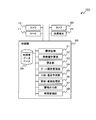
- FIG. 1 is a block diagram showing a configuration example of an embodiment of a data management system according to the present invention.
- the data management system 100 of the present embodiment includes a camera 10 and a gate 11 in the vicinity of the entrance to the facility. Further, the data management system 100 of the present embodiment includes a camera 20 and a payment terminal 21 near the exit of the facility. Further, the data management system 100 of the present embodiment includes a control unit 30 that controls these devices.
- the camera 10 is a device that acquires the biometric information of the user at the time of admission, and in the present embodiment, the face image of the user is captured.
- information other than the face image for example, fingerprint, voiceprint, etc.
- the data management system 100 may be provided with an appropriate sensor (fingerprint authentication device, microphone, etc.) instead of the camera 10. Therefore, the camera 10 that acquires the biometric information of the user can be referred to as a biometric information acquisition device.
- the camera 10 transmits the acquired face image to the control unit 30. At this time, the camera 10 may also transmit information that identifies itself (for example, an IP address or a camera ID).
- the gate 11 is a device that operates under control by a control unit 30 (specifically, a gate opening / closing management unit 34 and an alarm output unit 37) described later.
- the control method of the gate 11 will be described later.
- the camera 20 is a device that acquires the biometric information of the user at the time of payment at the facility, and in the present embodiment, the face image of the user is captured. As with the camera 10, another sensor may be used depending on the acquired biological information. Therefore, the camera 20 can also be called a biological information acquisition device. At this time, the camera 20 may also transmit information that identifies itself (for example, an IP address or a camera ID).
- the payment terminal 21 is a device that makes a payment for a user using biometric information. Specifically, the payment terminal 21 authenticates the user based on the biometric information and makes a payment based on the payment information.
- the content of the payment process performed by the payment terminal 21 is not particularly limited. Further, the payment terminal 21 of the present embodiment may output an alarm when the payment cannot be made by the control by the alarm output unit 37 described later.
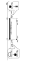
- FIG. 2 is an explanatory diagram showing an example of a process for authenticating a user.
- An image of the user 12 is taken by a camera 10 provided at the entrance / exit of the store, and as a result of authentication (collation with biometric information) by the control unit 30 described later, opening / closing processing of the gate 11 is performed. Further, an image of the user 12 is taken by the camera 20 provided at the store cashier, and as a result of authentication (collation with biometric information) by the control unit 30 described later, payment is made by the payment terminal 21.
- the control unit 30 includes a face detection unit 31, a feature amount calculation unit 32, a collation unit 33, a gate opening / closing management unit 34, a store entry / exit prediction unit 35, an update / registration processing unit 36, and an alarm output.
- a unit 37, a time management unit 38, and a user database 39 are included.
- the face detection unit 31 detects the face, which is the biometric information of the user, from the images taken by the camera 10 and the camera 20.
- the feature amount calculation unit 32 calculates the feature amount from the detected face of the user.
- the collation unit 33 collates the calculated feature amount with the biometric information stored in the user database 39 described later, and determines whether or not there is a matching user. If there is a user whose authentication data stored in the user database 39 matches the calculated feature amount, the collation unit 33 determines that the user has been successfully authenticated, and performs admission and payment processing. May be allowed. Since a method of detecting a person's face from an image, calculating a feature amount, and collating the person's face is widely known, detailed description thereof will be omitted here.
- the face detection unit 31, the feature amount calculation unit 32, and the collation unit 33 respond to each biometric information.
- the feature quantities may be extracted and collated.
- the gate opening / closing management unit 34 manages the opening / closing of the gate 11. Specifically, the gate opening / closing management unit 34 may instruct the gate 11 to open the gate 11 when the collating unit 33 determines that the user has been successfully authenticated, and the collating unit 33 may instruct the user to open. If it is determined that the authentication has not been successful, the gate 11 may be instructed not to open.
- the store entry / exit prediction unit 35 predicts the arrival time of the user at the facility and the exit time of the user from the facility. In the present embodiment, the store entry / exit prediction unit 35 predicts the store entry time and the store exit time of the user. Since the store entry / exit prediction unit 35 predicts the arrival time of the user at the facility and the exit time of the user from the facility, the store entry / exit prediction unit 35 predicts the arrival time. It can be called a department and an exit time prediction department.
- the store entry / exit prediction unit 35 predicts the arrival time (store visit time) of the user at the facility (store).
- the method by which the store entry / exit prediction unit 35 predicts the arrival time is arbitrary.
- the store entry / exit prediction unit 35 may predict the visit time of the user by using, for example, a model that predicts the store entry based on the attribute information and regularity of the user. Examples of attribute information include location information and preference. In addition, examples of regularity include purchasing information and weather. Further, in the case of a venue where an event is held, the store entry / exit prediction unit 35 may predict the arrival time of the user based on a time schedule such as an opening time or a start time.
- the store entry / exit prediction unit 35 predicts the exit time (store exit time) of the user from the facility (store).
- the method by which the store entry / exit prediction unit 35 predicts the exit time is also arbitrary.
- the store entry / exit prediction unit 35 predicts the user's exit time by using a model that predicts the store exit based on the user's attribute information and regularity, similar to the arrival time prediction. May be good.
- the store entry / exit prediction unit 35 may machine-learn a prediction model for, for example, the facility stay time for each age and / or gender.
- the store entry / exit prediction unit 35 may acquire the age and / or gender of the user at the time of entering the store, and predict the exit time based on the acquired information and the learned prediction model. ..
- the age and / or gender of the user may be estimated from, for example, an image taken by the camera 10 or may be obtained from the registered information.
- the store entry / exit prediction unit 35 may use, for example, after a user enters a facility (store), the user's flow line analysis result or regularity after payment (for example, a few minutes after payment). You may predict the exit time based on (such as leaving the store). Examples of the flow line analysis include travel time and residence time in the store. Further, in the case of a venue where an event is held, the store entry / exit prediction unit 35 may predict the user's exit time based on a time schedule such as closing time or closing time.
- the update / registration processing unit 36 updates and registers the user database 39. Specifically, the update / registration processing unit 36 sets data used for user authentication (hereinafter, may be referred to as authentication data) as an external device (not shown) based on the predicted arrival time. And register it in a local storage device (eg, user database 39).
- authentication data is user's biometric information (for example, facial features).
- the update / registration processing unit 36 acquires the user's payment information from the external device together with the user's authentication data.
- the external device is, for example, a device connected to a WAN (Wide Area Network) (that is, not locally), and an example is a cloud server.
- the local storage device is, for example, a storage server connected to a LAN (Local Area Network) in the facility or an IoT (Internet of Things) gateway. That is, in the present embodiment, since the amount of data stored locally is small, it is possible to realize a local storage device even with an IoT gateway having a small device size and capacity.
- the update / registration processing unit 36 may acquire authentication data and payment information from an external device when the predicted arrival time arrives, or may acquire it after the predicted arrival time. If authentication data is required for the predicted arrival time, it may be acquired before the predicted arrival time by a predetermined period.
- the update / registration processing unit 36 deletes the authentication data (payment information, if any) from the storage device (for example, the user database 39) after the predicted exit time.
- the update / registration processing unit 36 may delete the authentication data and the payment information from the external device when the predicted exit time is reached, and deletes the authentication data and the payment information from the predicted exit time until a predetermined period elapses. You may.
- the update / registration processing unit 36 of the present embodiment registers and deletes the authentication data and the payment information
- the update / registration processing unit 36 can be referred to as the registration unit and the deletion unit. ..
- FIG. 3 is an explanatory diagram showing an example of a process of holding data in a storage device.
- the storage device in the store does not store the user's biological information or payment information.
- biometric information and payment information are downloaded from the database (cloud) to the storage device in the store based on the predicted arrival time of the user.
- the biometric information and payment information are stored in the store only during the expected stay period, the data used for local authentication can be retained for the minimum necessary period while maintaining the response at the time of authentication.
- the alarm output unit 37 controls to output an alarm to the gate 11 and the payment terminal 21. Specifically, the alarm output unit 37 controls to output an alarm to the gate 11 and the payment terminal 21 when the user cannot be authenticated or the payment process cannot be performed.
- the alarm output unit 37 may control to output an alarm when, for example, the collation unit 33 determines that a user matching the biometric information does not exist in the user database 39.
- the user database 39 is a database that stores various information of users.
- the user database 39 stores the biometric information and the payment information of the user.
- the user database 39 stores the predicted arrival time of the user (estimated entry time) and the predicted exit time of the user (estimated exit time). For the arrival time and the exit time, the time predicted by the store entry / exit prediction unit 35 is registered by the update / registration processing unit 36.
- FIG. 4 is an explanatory diagram showing an example of information stored in the user database 39.
- the "user ID” is a field for storing an ID that uniquely identifies the user.
- the "biological information” is a field for storing the biometric information (feature amount, etc.) of the user.
- the “payment information” is a field for storing the payment information (credit card number, etc.) of the user.
- the "estimated store entry time” is a field for storing the estimated entrance time of the user.
- the “estimated store closing time” is a field for storing the estimated closing time of the user.
- the user database 39 is realized by, for example, a magnetic disk or the like.
- the time management unit 38 manages the user's entry time and exit time. For example, when the time management unit 38 reaches the store entry time or the store exit time registered in the user database 39, the time management unit 38 may notify each configuration included in the control unit 30 to that effect. In addition, the time management unit 38 may notify when a predetermined time is reached before the store entry time, or may notify when a predetermined time has elapsed after the store exit time.
- Control unit 30 (more specifically, face detection unit 31, feature amount calculation unit 32, collation unit 33, gate opening / closing management unit 34, store entry / exit prediction unit 35, update / registration processing unit 36.
- the alarm output unit 37 and the time management unit 38) are realized by a computer processor (for example, a CPU (Central Processing Unit) or a GPU (Graphics Processing Unit)) that operates according to a program (data management program).
- a computer processor for example, a CPU (Central Processing Unit) or a GPU (Graphics Processing Unit)
- the program is stored in a storage unit (not shown) of the data management system 100, the processor reads the program, and according to the program, the control unit 30 (more specifically, the face detection unit 31 and the feature amount calculation unit). It may operate as 32, a collation unit 33, a gate opening / closing management unit 34, a store entry / exit prediction unit 35, an update / registration processing unit 36, an alarm output unit 37, and a time management unit 38). .. Further, the function of the data management system 100 may be provided in the SaaS (Software as a Service) format.
- SaaS Software as a Service
- control unit 30 (more specifically, the face detection unit 31, the feature amount calculation unit 32, the collation unit 33, the gate opening / closing management unit 34, the store entry / exit prediction unit 35, and the update / registration processing unit).
- the 36, the alarm output unit 37, and the time management unit 38) may each be realized by dedicated hardware.
- a part or all of each component of each device may be realized by a general-purpose or dedicated circuit (circuitry), a processor, or a combination thereof. These may be composed of a single chip or may be composed of a plurality of chips connected via a bus.
- a part or all of each component of each device may be realized by a combination of the above-mentioned circuit or the like and a program.
- each component of the data management system 100 when a part or all of each component of the data management system 100 is realized by a plurality of information processing devices and circuits, the plurality of information processing devices and circuits may be centrally arranged. It may be distributed.
- the information processing device, the circuit, and the like may be realized as a form in which each of the client-server system, the cloud computing system, and the like is connected via a communication network.
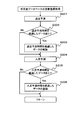
- FIG. 5 is a flowchart showing an outline of the operation of the data management system 100.
- the store entry / exit prediction unit 35 predicts the arrival time of the user at the facility (step S11).
- the update / registration processing unit 36 acquires the authentication data from the external device based on the predicted arrival time and registers it in the local storage device (step S12).
- the store entry / exit prediction unit 35 predicts the exit time of the user from the facility (step S13), and the update / registration processing unit 36 outputs the authentication data after the predicted user exit time. Delete from the storage device (step S14).
- FIG. 6 is a flowchart showing a specific operation example of the data management system 100 of the present embodiment.
- a store is illustrated as a facility, and face recognition is exemplified as an authentication method.
- biometric information and payment information are assumed as the data to be registered and deleted in the user database 39.
- the update / registration processing unit 36 After starting the face authentication control process, the update / registration processing unit 36 performs the update registration process of the user database 39 (step S101). The details of the update registration process will be described later.
- the camera 10 attached to the gate 11 or the camera 20 attached to the payment terminal 21 acquires the captured image and inputs it to the control unit 30 (step S102).
- the face detection unit 31 performs a process of detecting the face of the user of the store based on the input video (step S103). If no face is detected (No in step S104), the processes after step S103 are repeated.
- step S104 when a face is detected (Yes in step S104), the feature amount calculation unit 32 calculates the feature amount of the detected face (step S105). Then, the collation unit 33 searches the user database 39 based on the calculated feature amount and performs collation (step S106).
- the alarm output unit 37 controls to output an alarm to the gate 11 and the payment terminal 21 (step S111).
- the gate 11 and the payment terminal 21 may notify the user that authentication is not possible based on the control by the alarm output unit 37.
- a method of notifying the user for example, there is a method of displaying an error on a terminal that the user can see, such as a display attached to the gate, an LED (Light Emitting Diode), and a display of a payment terminal. ..
- the gate opening / closing management unit 34 determines whether or not the camera that captured the image is a gate camera (step S108).
- the gate opening / closing management unit 34 may determine the camera based on, for example, the IP address or the camera ID.
- step S108 When the camera that captured the image is a gate camera (Yes in step S108), the gate opening / closing management unit 34 controls the gate 11 to open the gate (step S109). On the other hand, when the camera that captured the image is not a gate camera (No in step S108), the update / registration processing unit 36 transmits payment information to the payment terminal 21, and the payment terminal 21 performs payment processing (step S110). ).
- FIG. 7 is a flowchart showing an example of the update registration process of the user database 39.
- a store is illustrated as a facility, and user information is managed in the user database 39 illustrated in FIG.
- the store entry / exit prediction unit 35 predicts the store exit (step S201), and the update / registration processing unit 36 registers the prediction result in the store exit prediction time of the user database 39. ..
- the store entry / exit prediction unit 35 may determine the user's exit from the store by face recognition at the exit.
- the time management unit 38 After predicting the store closure, the time management unit 38 confirms the estimated store exit time of each user in the user database 39. When there is data for which the estimated store exit time has passed (Yes in step S202), the update / registration processing unit 36 deletes the data of the user whose estimated exit time has passed (step S203). On the other hand, when there is no data for which the estimated store exit time has passed (No in step S202), the processing after step S204 shown below is performed.
- the store entry / exit prediction unit 35 makes a store entry prediction (step S204), and the update / registration processing unit 36 registers the prediction result in the store entry prediction time of the user database 39.
- the time management unit 38 confirms the store entry estimated time of each user in the user database 39.
- the update / registration processing unit 36 registers the data of the user for whom the estimated time of entering the store has passed (step S206), and is illustrated in FIG.
- the process is returned to step S102 (step S207).
- the process is returned in the same manner (step S207).
- the collation unit 33 may determine that authentication is not possible when the user tries to perform the payment process. Further, if the user tries to leave the facility without performing the payment processing after the expected exit time has passed, the camera 20 cannot acquire the biometric information of the user, so the collation unit 33 performs any processing. You don't have to do it.
- the store entry / exit prediction unit 35 predicts the arrival time of the user at the facility, and the update / registration processing unit 36 authenticates based on the predicted arrival time. Obtain data from an external device and register it in a local storage device.
- the store entry / exit prediction unit 35 predicts the exit time of the user from the facility, and the update / registration processing unit 36 deletes the authentication data from the storage device after the predicted user exit time. do. Therefore, it is possible to appropriately manage the data used for local authentication while maintaining the response at the time of authentication.
- the update / registration processing unit 36 deletes the biometric information and the payment information stored corresponding to the user ID of the user database 39. Therefore, biometric information and payment information can be deleted without face recognition and even if a certain number of visitors do not exist, so that it is possible to prevent these data from remaining on the store's equipment. It is possible to ensure privacy. Further, in the present embodiment, the update / registration processing unit 36 registers the biometric information and the payment information of the user whose estimated entry time has passed in the user database 39. Therefore, since the biometric information and the payment information of the user are held in the device of the store only while entering the store, privacy can be ensured.
- local data is registered and deleted based on the time predicted by the store entry / exit prediction unit 35. Therefore, it becomes possible to dynamically register and delete data.
- the authentication data of the user who is expected to arrive is downloaded from the external device (cloud) and stored in the local storage device (user database 39), and the authentication data is not stored in the storage device.
- the person the case where it is judged that the authentication is not possible was explained.
- the collation unit 33 may inquire of the external device whether there is a user who matches the calculated feature amount.
- the external device may have a configuration corresponding to the collation unit 33 of the present embodiment. With such a configuration, it is possible to perform authentication even for a user whose authentication data is not registered in the local storage device.
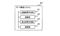
- FIG. 8 is a block diagram showing an outline of the data management system according to the present invention.
- the data management system 80 is a data management system (for example, data management system 100) that manages data of a user (for example, a customer) who uses a facility (for example, a store), and is sent to the user's facility.
- Arrival time prediction unit 81 (for example, store entry / exit prediction unit 35) that predicts the arrival time (for example, store visit time) of the user, and authentication data (for example, authentication data used for user authentication) based on the predicted arrival time.
- a registration unit 82 for example, an update / registration processing unit 36 that acquires biometric information) from an external device (for example, a cloud server) and registers it in a local storage device (for example, a storage server), and a user's
- the exit time prediction unit 83 for example, the store entry / exit prediction unit 35
- the exit time prediction unit 83 that predicts the exit time from the facility (for example, the store exit time) and the authentication data are stored in the storage device after the predicted user exit time.
- a deletion unit 84 for example, an update / registration processing unit 36 to be deleted from.
- the registration unit 82 may acquire the user authentication data from the external device and register it in the local storage device when the predicted arrival time is reached, and the deletion unit 84 may obtain the user authentication data from the external device and register the user authentication data in the local storage device.
- the authentication data may be deleted from the storage device at the expected exit time.
- the registration unit 82 may acquire the biometric information of the user (for example, the feature amount of the face) as the authentication data.
- the data management system 80 includes a biometric information acquisition device (for example, a camera 10 and a camera 20) that acquires the biometric information of the user, and a feature amount calculation unit (for example, face detection) that calculates the feature amount of the acquired biometric information.
- a unit 31 and a feature amount calculation unit 32) may be provided, and a collation unit (for example, a collation unit 33) for collating the calculated feature amount with the authentication data stored in the local storage device may be provided. Then, if there is a user whose authentication data stored in the local storage device and the calculated feature amount match, the collating unit may determine that the user has been successfully authenticated.
- the registration unit 82 acquires the payment information which is the information related to the payment of the user together with the authentication data of the user from the external device, and the deletion unit 84 deletes the payment information together with the authentication data from the storage device. good.
- the payment information can be used only for the time when authentication is required.
- the exit time prediction unit 83 may predict the exit time after the user enters the facility, based on the user's flow line analysis result or the regularity after settlement. With such a configuration, it becomes possible to dynamically predict the exit time according to the movement of the user after entering.
- the present invention is suitably applied to a data management system that manages locally stored data.
- the present invention can be suitably applied to various systems in which personal information is downloaded from the cloud to a device and operated.
Abstract
A data management system 80 manages data of a user who uses a facility. An arrival time prediction unit 81 predicts the arrival time of the user at the facility. A registration unit 82 acquires, from an external device, authentication data used for authenticating the user, using the predicted arrival time as a reference, and registers the authentication data in a local storage device. An exit time prediction unit 83 predicts the exit time of the user from the facility. A deletion unit 84 deletes the authentication data from the storage device after the predicted exit time of the user.
Description
本発明は、ローカルに保存されるデータを管理するデータ管理システム、データ管理方法およびデータ管理プログラムに関する。
The present invention relates to a data management system, a data management method, and a data management program for managing locally stored data.
近年、セキュリティや利便性の観点から顔認証を用いたシステムが普及している。例えば、コンビニエンスストアのような店舗においては、人口減少による従業員の減少という将来の課題を解決するため無人店舗の実証実験が進んでおり、店舗への入店および退店の管理や決済に顔認証が用いられている。
In recent years, systems using face recognition have become widespread from the viewpoint of security and convenience. For example, in stores such as convenience stores, unmanned store demonstration experiments are underway to solve the future problem of a decrease in employees due to population decline, and they are faced with management and settlement of store entrances and exits. Authentication is used.
無人店舗で顔認証を行う場合、利便性の観点からレスポンス性能を求められる。また、無人店舗が普及した場合、利用者の数が多くなるため、データベースが肥大化することが推測される。そのため、データベースをクラウドで管理し、店舗内に設置したエッジデバイス等の装置に一部のデータをダウンロードし、店舗で顔認証することでレスポンス性能を高める構成が想定される。
When performing face recognition in an unmanned store, response performance is required from the viewpoint of convenience. In addition, if unmanned stores become widespread, the number of users will increase, and it is presumed that the database will become bloated. Therefore, it is assumed that the database is managed in the cloud, some data is downloaded to a device such as an edge device installed in the store, and face authentication is performed at the store to improve the response performance.
一方、ダウンロードされるデータは、入退店や決済で使用されるため、生体情報の他にクレジットカード情報といった決済情報も含まれる。そのため、無人店舗で入退店や決済に顔認証を用いる場合、プライバシーやセキュリティの観点でデータを管理する必要がある。例えば、店舗内の装置が盗まれた場合、一時的にダウンロードした生体情報やクレジットカード情報が流出し、悪意のある人物に悪用される可能性がある。そのため、適切なタイミングで一時的にダウンロードしたデータの置き換え(リプレース)を行う必要がある。
On the other hand, since the downloaded data is used for entering and exiting stores and making payments, payment information such as credit card information is included in addition to biometric information. Therefore, when face recognition is used for entering / exiting or making payments at an unmanned store, it is necessary to manage the data from the viewpoint of privacy and security. For example, if a device in a store is stolen, temporarily downloaded biometric information or credit card information may be leaked and misused by a malicious person. Therefore, it is necessary to temporarily replace the downloaded data at an appropriate timing.
特許文献1には、顔認証に用いられる顔画像データを利用者IDと対応付けて管理する顔認証データベース管理方法が記載されている。特許文献1に記載された方法では、過去の顔認証の決定に用いられた顔画像データの利用度を示す認証利用度に基づいて顔画像データを顔認証データベースから削除し、新たに検出された顔画像データを登録する。
Patent Document 1 describes a face authentication database management method that manages face image data used for face authentication in association with a user ID. In the method described in Patent Document 1, the face image data is deleted from the face recognition database based on the authentication usage degree indicating the usage degree of the face image data used in the determination of the face recognition in the past, and the face image data is newly detected. Register face image data.
また、特許文献2には、顔認証を用いた情報処理システムが記載されている。特許文献2に記載されたシステムでは、センタサーバが店舗サーバからの問合せに対して登録されている顔情報を店舗サーバのデータベースに提供し、店舗サーバは、退店または所定時間以上の経過の確認後、顧客の来店者情報をデータベースからから削除する。
Further, Patent Document 2 describes an information processing system using face recognition. In the system described in Patent Document 2, the center server provides the face information registered in response to the inquiry from the store server to the database of the store server, and the store server confirms that the store has closed or the lapse of a predetermined time or more has passed. After that, the customer's visitor information is deleted from the database.
一方、特許文献1に記載された方法では、顔認証が行われないと店舗の装置からデータが削除されない(すなわち、入店者が来るまでデータが削除されない)。また、特許文献1に記載された方法では、格納領域に空きがなくなってからデータが削除されるため、一定人数の入店者が来るまでデータが削除されない。さらに、特許文献1に記載された方法では、退店後にも関わらず、登録時刻が最も古い顔画像しかデータが削除されない。したがって、過去に利用した利用者の生体情報および決済情報がローカルの店舗の装置に残り続けてしまうため、この装置が盗難にあってしまうと、情報が流出し悪用されるおそれがある。
On the other hand, in the method described in Patent Document 1, data is not deleted from the device of the store unless face recognition is performed (that is, the data is not deleted until a visitor arrives). Further, in the method described in Patent Document 1, since the data is deleted after the storage area becomes full, the data is not deleted until a certain number of visitors arrive. Further, in the method described in Patent Document 1, only the face image having the oldest registration time is deleted even after the store is closed. Therefore, the biometric information and payment information of the user who used the past will continue to remain in the device of the local store, and if this device is stolen, the information may be leaked and misused.
また、特許文献2に記載されたシステムでは、撮影画像から来店者の顔情報を抽出した後、顔認証の対象とする登録顔情報をセンタサーバから取得する。このように、認証ごとにセンタサーバへ問い合わせる方式では、顔認証に時間を要してしまうため、顔認証時のレスポンスを維持させることは難しい。
Further, in the system described in Patent Document 2, after extracting the face information of the visitor from the photographed image, the registered face information to be the target of face authentication is acquired from the center server. In this way, in the method of inquiring to the center server for each authentication, it takes time for face authentication, so it is difficult to maintain the response at the time of face authentication.
そこで、本発明では、認証時のレスポンスを維持しつつ、ローカルでの認証に用いられるデータを適切に管理できるデータ管理システム、データ管理方法およびデータ管理プログラムを提供することを目的とする。
Therefore, an object of the present invention is to provide a data management system, a data management method, and a data management program that can appropriately manage data used for local authentication while maintaining a response at the time of authentication.
本発明によるデータ管理システムは、施設を利用する利用者のデータを管理するデータ管理システムであって、利用者の施設への到着時間を予測する到着時間予測部と、予測された到着時間を基準に、利用者の認証に用いられる認証データを外部装置から取得して、ローカルの記憶装置に登録する登録部と、利用者の施設からの退出時間を予測する退出時間予測部と、予測された利用者の退出時間以降に、認証データを記憶装置から削除する削除部とを備えたことを特徴とする。
The data management system according to the present invention is a data management system that manages data of users who use the facility, and is based on an arrival time prediction unit that predicts the arrival time of the user at the facility and the predicted arrival time. In addition, a registration unit that acquires authentication data used for user authentication from an external device and registers it in a local storage device, and an exit time prediction unit that predicts the exit time of the user from the facility are predicted. It is characterized by having a deletion unit that deletes the authentication data from the storage device after the user's exit time.
本発明によるデータ管理方法は、施設を利用する利用者のデータを管理するデータ管理方法であって、利用者の施設への到着時間を予測し、予測された到着時間を基準に、利用者の認証に用いられる認証データを外部装置から取得して、ローカルの記憶装置に登録し、利用者の施設からの退出時間を予測し、予測された利用者の退出時間以降に、認証データを記憶装置から削除することを特徴とする。
The data management method according to the present invention is a data management method for managing the data of the user who uses the facility, predicts the arrival time of the user at the facility, and uses the predicted arrival time as a reference for the user. The authentication data used for authentication is acquired from an external device, registered in a local storage device, the user's exit time from the facility is predicted, and the authentication data is stored in the storage device after the predicted user exit time. It is characterized by being deleted from.
本発明によるデータ管理プログラムは、施設を利用する利用者のデータを管理するコンピュータに適用されるデータ管理プログラムであって、コンピュータに、利用者の施設への到着時間を予測する到着時間予測処理、予測された到着時間を基準に、利用者の認証に用いられる認証データを外部装置から取得して、ローカルの記憶装置に登録する登録処理、利用者の施設からの退出時間を予測する退出時間予測処理、および、予測された利用者の退出時間以降に、認証データを記憶装置から削除する削除処理を実行させることを特徴とする。
The data management program according to the present invention is a data management program applied to a computer that manages data of a user who uses the facility, and is an arrival time prediction process that predicts the arrival time of the user to the facility on the computer. Based on the predicted arrival time, the registration process of acquiring the authentication data used for user authentication from an external device and registering it in the local storage device, and the exit time prediction that predicts the exit time of the user from the facility. It is characterized in that the processing and the deletion processing for deleting the authentication data from the storage device are executed after the predicted exit time of the user.
本発明によれば、認証時のレスポンスを維持しつつ、ローカルでの認証に用いられるデータを適切に管理できる。
According to the present invention, it is possible to appropriately manage the data used for local authentication while maintaining the response at the time of authentication.
以下、本発明の実施形態を図面を参照して説明する。本実施形態では、施設を利用する利用者のデータをローカルで管理するシステムの一例として、無人店舗を利用する顧客のデータを管理するシステムについて説明する。具体的には、本実施形態では、生体情報をもとに店舗への入退店を管理するシステムについて説明する。ただし、本発明が用いられる施設は店舗に限定されず、例えば、大会やコンサートなどが行われる会場などであってもよい。さらに、本実施形態では、決済に用いられる情報(以下、決済情報と記す。)をもとに利用者の決済を管理する方法についても説明する。
Hereinafter, embodiments of the present invention will be described with reference to the drawings. In this embodiment, as an example of a system for locally managing data of users who use facilities, a system for managing data of customers who use unmanned stores will be described. Specifically, in the present embodiment, a system for managing entry / exit to / from a store based on biometric information will be described. However, the facility in which the present invention is used is not limited to a store, and may be, for example, a venue where a competition or a concert is held. Further, in the present embodiment, a method of managing the user's payment based on the information used for the payment (hereinafter referred to as payment information) will also be described.
図1は、本発明によるデータ管理システムの一実施形態の構成例を示すブロック図である。本実施形態のデータ管理システム100は、施設への入場口近辺に、カメラ10とゲート11とを備えている。また、本実施形態のデータ管理システム100は、施設の退場口近辺に、カメラ20と、決済端末21とを備えている。さらに、本実施形態のデータ管理システム100は、これらの装置を制御する制御部30を備えている。
FIG. 1 is a block diagram showing a configuration example of an embodiment of a data management system according to the present invention. The data management system 100 of the present embodiment includes a camera 10 and a gate 11 in the vicinity of the entrance to the facility. Further, the data management system 100 of the present embodiment includes a camera 20 and a payment terminal 21 near the exit of the facility. Further, the data management system 100 of the present embodiment includes a control unit 30 that controls these devices.
カメラ10は、入場時に利用者の生体情報を取得する装置であり、本実施形態では、利用者の顔画像を撮影する。なお、利用者の生体情報として、顔画像以外の他の情報(例えば、指紋や声紋など)が利用されてもよい。その場合、データ管理システム100は、カメラ10の代わりに適切なセンサ(指紋認証装置やマイクロフォンなど)を備えればよい。そのため、利用者の生体情報を取得するカメラ10のことを、生体情報取得装置ということができる。カメラ10は、取得した顔画像を制御部30に送信する。このとき、カメラ10は、自身を識別する情報(例えば、IPアドレスやカメラID)を合わせて送信してもよい。
The camera 10 is a device that acquires the biometric information of the user at the time of admission, and in the present embodiment, the face image of the user is captured. In addition, information other than the face image (for example, fingerprint, voiceprint, etc.) may be used as the biometric information of the user. In that case, the data management system 100 may be provided with an appropriate sensor (fingerprint authentication device, microphone, etc.) instead of the camera 10. Therefore, the camera 10 that acquires the biometric information of the user can be referred to as a biometric information acquisition device. The camera 10 transmits the acquired face image to the control unit 30. At this time, the camera 10 may also transmit information that identifies itself (for example, an IP address or a camera ID).
ゲート11は、後述する制御部30(具体的には、ゲート開閉管理部34および警報出力部37)による制御により動作する装置である。なお、ゲート11の制御方法については後述される。
The gate 11 is a device that operates under control by a control unit 30 (specifically, a gate opening / closing management unit 34 and an alarm output unit 37) described later. The control method of the gate 11 will be described later.
カメラ20は、施設における決済時に利用者の生体情報を取得する装置であり、本実施形態では、利用者の顔画像を撮影する。なお、カメラ10と同様に、取得する生体情報に応じて他のセンサが用いられてもよい。そのため、カメラ20のことも、生体情報取得装置ということができる。このとき、カメラ20も、自身を識別する情報(例えば、IPアドレスやカメラID)を合わせて送信してもよい。
The camera 20 is a device that acquires the biometric information of the user at the time of payment at the facility, and in the present embodiment, the face image of the user is captured. As with the camera 10, another sensor may be used depending on the acquired biological information. Therefore, the camera 20 can also be called a biological information acquisition device. At this time, the camera 20 may also transmit information that identifies itself (for example, an IP address or a camera ID).
決済端末21は、生体情報を用いて利用者の決済を行う装置である。具体的には、決済端末21は、生体情報をもとに利用者の認証を行い、決済情報に基づいて利用者の決済を行う。なお、決済端末21が行う決済処理の内容は、特に限定されない。また、本実施形態の決済端末21は、後述する警報出力部37による制御により、決済ができなかった場合に、警報を出力してもよい。
The payment terminal 21 is a device that makes a payment for a user using biometric information. Specifically, the payment terminal 21 authenticates the user based on the biometric information and makes a payment based on the payment information. The content of the payment process performed by the payment terminal 21 is not particularly limited. Further, the payment terminal 21 of the present embodiment may output an alarm when the payment cannot be made by the control by the alarm output unit 37 described later.
図2は、利用者の認証を行う処理の例を示す説明図である。店舗の出入口に設けられたカメラ10で、利用者12の画像が撮影され、後述する制御部30による認証(生体情報との照合)の結果、ゲート11の開閉処理が行われる。また、店舗レジに設けられたカメラ20で、利用者12の画像が撮影され、後述する制御部30による認証(生体情報との照合)の結果、決済端末21による決済が行われる。
FIG. 2 is an explanatory diagram showing an example of a process for authenticating a user. An image of the user 12 is taken by a camera 10 provided at the entrance / exit of the store, and as a result of authentication (collation with biometric information) by the control unit 30 described later, opening / closing processing of the gate 11 is performed. Further, an image of the user 12 is taken by the camera 20 provided at the store cashier, and as a result of authentication (collation with biometric information) by the control unit 30 described later, payment is made by the payment terminal 21.
制御部30は、顔検出部31と、特徴量計算部32と、照合部33と、ゲート開閉管理部34と、入店・退店予測部35と、更新・登録処理部36と、警報出力部37と、時間管理部38と、利用者データベース39とを含む。
The control unit 30 includes a face detection unit 31, a feature amount calculation unit 32, a collation unit 33, a gate opening / closing management unit 34, a store entry / exit prediction unit 35, an update / registration processing unit 36, and an alarm output. A unit 37, a time management unit 38, and a user database 39 are included.
顔検出部31は、カメラ10およびカメラ20が撮影した画像から利用者の生体情報である顔を検出する。また、特徴量計算部32は、検出した利用者の顔から特徴量を計算する。照合部33は、計算された特徴量と、後述する利用者データベース39に記憶された生体情報とを照合し、一致する利用者が存在するか否か判断する。照合部33は、利用者データベース39に記憶された認証データと、計算された特徴量とが一致する利用者が存在する場合、その利用者の認証に成功したと判断して、入場や決済処理を許可してもよい。なお、画像から人物の顔を検出し、特徴量を算出して照合する方法は広く知られているため、ここでは詳細な説明を省略する。
The face detection unit 31 detects the face, which is the biometric information of the user, from the images taken by the camera 10 and the camera 20. In addition, the feature amount calculation unit 32 calculates the feature amount from the detected face of the user. The collation unit 33 collates the calculated feature amount with the biometric information stored in the user database 39 described later, and determines whether or not there is a matching user. If there is a user whose authentication data stored in the user database 39 matches the calculated feature amount, the collation unit 33 determines that the user has been successfully authenticated, and performs admission and payment processing. May be allowed. Since a method of detecting a person's face from an image, calculating a feature amount, and collating the person's face is widely known, detailed description thereof will be omitted here.
また、本実施形態では、生体情報として顔画像以外の他の情報(例えば、指紋や声紋など)を用いる場合、顔検出部31、特徴量計算部32および照合部33は、各生体情報に応じた特徴量を抽出して照合を行えばよい。
Further, in the present embodiment, when information other than the face image (for example, fingerprint, voiceprint, etc.) is used as the biometric information, the face detection unit 31, the feature amount calculation unit 32, and the collation unit 33 respond to each biometric information. The feature quantities may be extracted and collated.
ゲート開閉管理部34は、ゲート11の開閉を管理する。具体的には、ゲート開閉管理部34は、照合部33が利用者の認証に成功したと判断した場合に、ゲート11に対して開放を指示してもよいし、照合部33が利用者の認証に成功していないと判断した場合に、ゲート11に対して開放しないと指示してもよい。
The gate opening / closing management unit 34 manages the opening / closing of the gate 11. Specifically, the gate opening / closing management unit 34 may instruct the gate 11 to open the gate 11 when the collating unit 33 determines that the user has been successfully authenticated, and the collating unit 33 may instruct the user to open. If it is determined that the authentication has not been successful, the gate 11 may be instructed not to open.
入店・退店予測部35は、利用者の施設への到着時間、および、利用者の施設からの退出時間を予測する。本実施形態では、入店・退店予測部35は、利用者の入店時間および退店時間を予測する。なお、入店・退店予測部35は、利用者の施設への到着時間、および、利用者の施設からの退出時間を予測することから、入店・退店予測部35を、到着時間予測部および退出時間予測部と言うことができる。
The store entry / exit prediction unit 35 predicts the arrival time of the user at the facility and the exit time of the user from the facility. In the present embodiment, the store entry / exit prediction unit 35 predicts the store entry time and the store exit time of the user. Since the store entry / exit prediction unit 35 predicts the arrival time of the user at the facility and the exit time of the user from the facility, the store entry / exit prediction unit 35 predicts the arrival time. It can be called a department and an exit time prediction department.
上述するように、入店・退店予測部35は、利用者の施設(店舗)への到着時間(来店時間)を予測する。入店・退店予測部35が到着時間を予測する方法は任意である。入店・退店予測部35は、例えば、利用者の属性情報や規則性をもとに入店を予測するモデルを用いて、利用者の来店時間を予測してもよい。属性情報の例として、位置情報や嗜好性などが挙げられる。また、規則性の例として、購買情報や天候などが挙げられる。また、イベントを行う会場などの場合、入店・退店予測部35は、開館時間や開演時間などのタイムスケジュールなどに基づいて利用者の到着時間を予測してもよい。
As described above, the store entry / exit prediction unit 35 predicts the arrival time (store visit time) of the user at the facility (store). The method by which the store entry / exit prediction unit 35 predicts the arrival time is arbitrary. The store entry / exit prediction unit 35 may predict the visit time of the user by using, for example, a model that predicts the store entry based on the attribute information and regularity of the user. Examples of attribute information include location information and preference. In addition, examples of regularity include purchasing information and weather. Further, in the case of a venue where an event is held, the store entry / exit prediction unit 35 may predict the arrival time of the user based on a time schedule such as an opening time or a start time.
同様に、入店・退店予測部35は、利用者の施設(店舗)からの退出時間(退店時間)を予測する。入店・退店予測部35が退出時間を予測する方法も任意である。入店・退店予測部35は、到着時間の予測と同様に、利用者の属性情報や規則性をもとに退店を予測するモデルを用いて、利用者の退店時間を予測してもよい。入店・退店予測部35は、例えば、年齢および/または性別ごとの施設滞在時間について予測モデルを機械学習しておいてもよい。この場合、入店・退店予測部35は、入店時に利用者の年齢および/または性別を取得し、取得した情報と学習済みの予測モデルとに基づいて、退出時間を予測してもよい。利用者の年齢および/または性別は、例えば、カメラ10が撮影した画像から推定されてもよく、登録された情報から取得されてもよい。
Similarly, the store entry / exit prediction unit 35 predicts the exit time (store exit time) of the user from the facility (store). The method by which the store entry / exit prediction unit 35 predicts the exit time is also arbitrary. The store entry / exit prediction unit 35 predicts the user's exit time by using a model that predicts the store exit based on the user's attribute information and regularity, similar to the arrival time prediction. May be good. The store entry / exit prediction unit 35 may machine-learn a prediction model for, for example, the facility stay time for each age and / or gender. In this case, the store entry / exit prediction unit 35 may acquire the age and / or gender of the user at the time of entering the store, and predict the exit time based on the acquired information and the learned prediction model. .. The age and / or gender of the user may be estimated from, for example, an image taken by the camera 10 or may be obtained from the registered information.
他にも、入店・退店予測部35は、例えば、利用者が施設(店舗)に入場後、その利用者の動線分析結果または決済後の規則性(例えば、決済後、数分後には退店する、など)に基づいて、退出時間を予測してもよい。動線分析として、例えば、店舗内の移動時間や滞留時間などが挙げられる。また、イベントを行う会場などの場合、入店・退店予測部35は、閉館時間や閉演時間などのタイムスケジュールなどに基づいて利用者の退出時間を予測してもよい。
In addition, the store entry / exit prediction unit 35 may use, for example, after a user enters a facility (store), the user's flow line analysis result or regularity after payment (for example, a few minutes after payment). You may predict the exit time based on (such as leaving the store). Examples of the flow line analysis include travel time and residence time in the store. Further, in the case of a venue where an event is held, the store entry / exit prediction unit 35 may predict the user's exit time based on a time schedule such as closing time or closing time.
更新・登録処理部36は、利用者データベース39の更新および登録処理を行う。具体的には、更新・登録処理部36は、予測された到着時間を基準に、利用者の認証に用いられるデータ(以下、認証データと記すこともある。)を外部装置(図示せず)から取得して、ローカルの記憶装置(例えば、利用者データベース39)に登録する。認証データの一例が、利用者の生体情報(例えば、顔の特徴量)である。また、更新・登録処理部36は、利用者の認証データと共に、その利用者の決済情報を外部装置から取得する。
The update / registration processing unit 36 updates and registers the user database 39. Specifically, the update / registration processing unit 36 sets data used for user authentication (hereinafter, may be referred to as authentication data) as an external device (not shown) based on the predicted arrival time. And register it in a local storage device (eg, user database 39). An example of authentication data is user's biometric information (for example, facial features). In addition, the update / registration processing unit 36 acquires the user's payment information from the external device together with the user's authentication data.
外部装置は、例えば、WAN(Wide Area Network )に接続された(すなわち、ローカルにはない)装置であり、一例として、クラウドサーバが挙げられる。また、ローカルの記憶装置は、例えば、施設内のLAN(Local Area Network)に接続されたストレージサーバや、IoT(Internet of Things)ゲートウェイである。すなわち、本実施形態では、ローカルで保存するデータ量が少なくて済むことから、装置サイズや容量が小規模なIoTゲートウェイでもローカルの記憶装置を実現することが可能である。
The external device is, for example, a device connected to a WAN (Wide Area Network) (that is, not locally), and an example is a cloud server. Further, the local storage device is, for example, a storage server connected to a LAN (Local Area Network) in the facility or an IoT (Internet of Things) gateway. That is, in the present embodiment, since the amount of data stored locally is small, it is possible to realize a local storage device even with an IoT gateway having a small device size and capacity.
更新・登録処理部36は、外部装置から認証データや決済情報を、予測された到着時間になったときに取得してもよく、予測された到着時間以降に取得してもよい。また、予測された到着時間には認証データが必要な場合、予測された到着時間よりも予め定めた期間だけ前に取得してもよい。
The update / registration processing unit 36 may acquire authentication data and payment information from an external device when the predicted arrival time arrives, or may acquire it after the predicted arrival time. If authentication data is required for the predicted arrival time, it may be acquired before the predicted arrival time by a predetermined period.
また、更新・登録処理部36は、予測された退出時間以降に、認証データ(存在する場合には、決済情報)を記憶装置(例えば、利用者データベース39)から削除する。更新・登録処理部36は、外部装置から認証データや決済情報を、予測された退出時間になったときに削除してもよく、予測された退出時間から予め定めた期間経過するまでに削除してもよい。
Further, the update / registration processing unit 36 deletes the authentication data (payment information, if any) from the storage device (for example, the user database 39) after the predicted exit time. The update / registration processing unit 36 may delete the authentication data and the payment information from the external device when the predicted exit time is reached, and deletes the authentication data and the payment information from the predicted exit time until a predetermined period elapses. You may.
このように、本実施形態の更新・登録処理部36は、認証データや決済情報の登録および削除を行うことから、更新・登録処理部36のことを、登録部および削除部と言うことができる。
As described above, since the update / registration processing unit 36 of the present embodiment registers and deletes the authentication data and the payment information, the update / registration processing unit 36 can be referred to as the registration unit and the deletion unit. ..
図3は、記憶装置にデータを保持する処理の例を示す説明図である。初期状態では、店舗内の記憶装置には、利用者の生体情報や決済情報は記憶されていない。この状態で、まず、予測された利用者の到着時間に基づいて、データベース(クラウド)から生体情報や決済情報が店舗内の記憶装置にダウンロードされる。
FIG. 3 is an explanatory diagram showing an example of a process of holding data in a storage device. In the initial state, the storage device in the store does not store the user's biological information or payment information. In this state, first, biometric information and payment information are downloaded from the database (cloud) to the storage device in the store based on the predicted arrival time of the user.
予測された到着時間に利用者が店舗に到着すると、ダウンロードされた生体情報を用いて顔認証が行われ、入場が許可される。利用者が入場していると予測される期間(すなわち、店舗滞在時のみ)データが店舗の記憶装置に保持される。そして、顔認証により決済が行われ、利用者が退店した後、予測された退出時間になると、店舗の記憶装置に記憶された生体情報や決済情報がリプレース(削除)される。
When the user arrives at the store at the predicted arrival time, face recognition is performed using the downloaded biometric information and admission is permitted. Data is stored in the store's storage device for the period during which the user is expected to be in (that is, only when staying in the store). Then, the payment is made by face recognition, and when the predicted exit time comes after the user leaves the store, the biometric information and the payment information stored in the storage device of the store are replaced (deleted).
このように、予測される滞在期間中にのみ生体情報や決済情報を店舗の記憶するため、認証時のレスポンスを維持しつつ、ローカルでの認証に用いられるデータを必要最低限の期間保持できる。
In this way, since the biometric information and payment information are stored in the store only during the expected stay period, the data used for local authentication can be retained for the minimum necessary period while maintaining the response at the time of authentication.
警報出力部37は、ゲート11や決済端末21に対して警報を出力する制御を行う。具体的には、警報出力部37は、利用者の認証ができなかった場合や決済処理ができなかった場合に、ゲート11や決済端末21に対して警報を出力する制御を行う。警報出力部37は、例えば、生体情報に一致する利用者が利用者データベース39に存在しないと照合部33が判断した場合に、警報を出力する制御を行ってもよい。
The alarm output unit 37 controls to output an alarm to the gate 11 and the payment terminal 21. Specifically, the alarm output unit 37 controls to output an alarm to the gate 11 and the payment terminal 21 when the user cannot be authenticated or the payment process cannot be performed. The alarm output unit 37 may control to output an alarm when, for example, the collation unit 33 determines that a user matching the biometric information does not exist in the user database 39.
利用者データベース39は、利用者の各種情報を記憶するデータベースである。本実施形態では、利用者データベース39は、利用者の生体情報や決済情報を記憶する。さらに、利用者データベース39は、予測された利用者の到着時間(入店予測時間)および予測された利用者の退出時間(退店予測時間)を記憶する。到着時間および退出時間には、入店・退店予測部35によって予測された時間が更新・登録処理部36によって登録される。
The user database 39 is a database that stores various information of users. In the present embodiment, the user database 39 stores the biometric information and the payment information of the user. Further, the user database 39 stores the predicted arrival time of the user (estimated entry time) and the predicted exit time of the user (estimated exit time). For the arrival time and the exit time, the time predicted by the store entry / exit prediction unit 35 is registered by the update / registration processing unit 36.
図4は、利用者データベース39が記憶する情報の例を示す説明図である。「利用者ID」は、利用者を一意に識別するIDを格納するフィールドである。「生体情報」は、利用者の生体情報(特徴量など)を格納するフィールドである。「決済情報」は、利用者の決済情報(クレジットカード番号など)を格納するフィールドである。「入店予測時間」は、利用者の入店予測時間を格納するフィールドである。「退店予測時間」は、利用者の退店予測時間を格納するフィールドである。利用者データベース39は、例えば、磁気ディスク等により実現される。
FIG. 4 is an explanatory diagram showing an example of information stored in the user database 39. The "user ID" is a field for storing an ID that uniquely identifies the user. The "biological information" is a field for storing the biometric information (feature amount, etc.) of the user. The "payment information" is a field for storing the payment information (credit card number, etc.) of the user. The "estimated store entry time" is a field for storing the estimated entrance time of the user. The "estimated store closing time" is a field for storing the estimated closing time of the user. The user database 39 is realized by, for example, a magnetic disk or the like.
時間管理部38は、利用者の入店時間および退店時間を管理する。時間管理部38は、例えば、利用者データベース39に登録されている入店時間や退店時間になったときに、制御部30に含まれる各構成にその旨を通知してもよい。また、時間管理部38は、入店時間より前の予め定めた時間になったときに通知してもよく、退店時間の後予め定めた時間が経過したときに通知してもよい。
The time management unit 38 manages the user's entry time and exit time. For example, when the time management unit 38 reaches the store entry time or the store exit time registered in the user database 39, the time management unit 38 may notify each configuration included in the control unit 30 to that effect. In addition, the time management unit 38 may notify when a predetermined time is reached before the store entry time, or may notify when a predetermined time has elapsed after the store exit time.
制御部30(より詳しくは、顔検出部31と、特徴量計算部32と、照合部33と、ゲート開閉管理部34と、入店・退店予測部35と、更新・登録処理部36と、警報出力部37と、時間管理部38)は、プログラム(データ管理プログラム)に従って動作するコンピュータのプロセッサ(例えば、CPU(Central Processing Unit )、GPU(Graphics Processing Unit))によって実現される。
Control unit 30 (more specifically, face detection unit 31, feature amount calculation unit 32, collation unit 33, gate opening / closing management unit 34, store entry / exit prediction unit 35, update / registration processing unit 36. The alarm output unit 37 and the time management unit 38) are realized by a computer processor (for example, a CPU (Central Processing Unit) or a GPU (Graphics Processing Unit)) that operates according to a program (data management program).
例えば、プログラムは、データ管理システム100の記憶部(図示せず)に記憶され、プロセッサは、そのプログラムを読み込み、プログラムに従って、制御部30(より詳しくは、顔検出部31と、特徴量計算部32と、照合部33と、ゲート開閉管理部34と、入店・退店予測部35と、更新・登録処理部36と、警報出力部37と、時間管理部38)として動作してもよい。また、データ管理システム100の機能がSaaS(Software as a Service )形式で提供されてもよい。
For example, the program is stored in a storage unit (not shown) of the data management system 100, the processor reads the program, and according to the program, the control unit 30 (more specifically, the face detection unit 31 and the feature amount calculation unit). It may operate as 32, a collation unit 33, a gate opening / closing management unit 34, a store entry / exit prediction unit 35, an update / registration processing unit 36, an alarm output unit 37, and a time management unit 38). .. Further, the function of the data management system 100 may be provided in the SaaS (Software as a Service) format.
また、制御部30(より詳しくは、顔検出部31と、特徴量計算部32と、照合部33と、ゲート開閉管理部34と、入店・退店予測部35と、更新・登録処理部36と、警報出力部37と、時間管理部38)は、それぞれが専用のハードウェアで実現されていてもよい。また、各装置の各構成要素の一部又は全部は、汎用または専用の回路(circuitry )、プロセッサ等やこれらの組合せによって実現されてもよい。これらは、単一のチップによって構成されてもよいし、バスを介して接続される複数のチップによって構成されてもよい。各装置の各構成要素の一部又は全部は、上述した回路等とプログラムとの組合せによって実現されてもよい。
Further, the control unit 30 (more specifically, the face detection unit 31, the feature amount calculation unit 32, the collation unit 33, the gate opening / closing management unit 34, the store entry / exit prediction unit 35, and the update / registration processing unit). The 36, the alarm output unit 37, and the time management unit 38) may each be realized by dedicated hardware. Further, a part or all of each component of each device may be realized by a general-purpose or dedicated circuit (circuitry), a processor, or a combination thereof. These may be composed of a single chip or may be composed of a plurality of chips connected via a bus. A part or all of each component of each device may be realized by a combination of the above-mentioned circuit or the like and a program.
また、データ管理システム100の各構成要素の一部又は全部が複数の情報処理装置や回路等により実現される場合には、複数の情報処理装置や回路等は、集中配置されてもよいし、分散配置されてもよい。例えば、情報処理装置や回路等は、クライアントサーバシステム、クラウドコンピューティングシステム等、各々が通信ネットワークを介して接続される形態として実現されてもよい。
Further, when a part or all of each component of the data management system 100 is realized by a plurality of information processing devices and circuits, the plurality of information processing devices and circuits may be centrally arranged. It may be distributed. For example, the information processing device, the circuit, and the like may be realized as a form in which each of the client-server system, the cloud computing system, and the like is connected via a communication network.
次に、本実施形態のデータ管理システム100の動作を説明する。まず、初めに、本実施形態のデータ管理システム100の動作概要を説明する。図5は、データ管理システム100の動作概要を示すフローチャートである。入店・退店予測部35は、利用者の施設への到着時間を予測する(ステップS11)。更新・登録処理部36は、予測された到着時間を基準に、認証データを外部装置から取得して、ローカルの記憶装置に登録する(ステップS12)。その後、入店・退店予測部35は、利用者の施設からの退出時間を予測し(ステップS13)、更新・登録処理部36は、予測された利用者の退出時間以降に、認証データを記憶装置から削除する(ステップS14)。
Next, the operation of the data management system 100 of this embodiment will be described. First, an outline of the operation of the data management system 100 of the present embodiment will be described. FIG. 5 is a flowchart showing an outline of the operation of the data management system 100. The store entry / exit prediction unit 35 predicts the arrival time of the user at the facility (step S11). The update / registration processing unit 36 acquires the authentication data from the external device based on the predicted arrival time and registers it in the local storage device (step S12). After that, the store entry / exit prediction unit 35 predicts the exit time of the user from the facility (step S13), and the update / registration processing unit 36 outputs the authentication data after the predicted user exit time. Delete from the storage device (step S14).
図6は、本実施形態のデータ管理システム100の具体的な動作例を示すフローチャートである。ここでは、施設として店舗を例示し、認証方法として顔認証を例示する。また、利用者データベース39へ登録および削除するデータとして、生体情報および決済情報を想定する。
FIG. 6 is a flowchart showing a specific operation example of the data management system 100 of the present embodiment. Here, a store is illustrated as a facility, and face recognition is exemplified as an authentication method. In addition, biometric information and payment information are assumed as the data to be registered and deleted in the user database 39.
顔認証の制御処理開始後、更新・登録処理部36は、利用者データベース39の更新登録処理を行う(ステップS101)。なお、更新登録処理の詳細については後述する。次に、ゲート11に併設されたカメラ10または決済端末21に併設されたカメラ20は、撮影した映像を取得して制御部30に入力する(ステップS102)。顔検出部31は、入力された映像をもとに店舗の利用者の顔を検出する処理を行う(ステップS103)。顔が検出されていない場合(ステップS104におけるNo)、ステップS103以降の処理が繰り返される。
After starting the face authentication control process, the update / registration processing unit 36 performs the update registration process of the user database 39 (step S101). The details of the update registration process will be described later. Next, the camera 10 attached to the gate 11 or the camera 20 attached to the payment terminal 21 acquires the captured image and inputs it to the control unit 30 (step S102). The face detection unit 31 performs a process of detecting the face of the user of the store based on the input video (step S103). If no face is detected (No in step S104), the processes after step S103 are repeated.
一方、顔が検出された場合(ステップS104におけるYes)、特徴量計算部32は、検出された顔の特徴量を計算する(ステップS105)。そして、照合部33は、計算された特徴量をもとに利用者データベース39を検索して、照合を行う(ステップS106)。
On the other hand, when a face is detected (Yes in step S104), the feature amount calculation unit 32 calculates the feature amount of the detected face (step S105). Then, the collation unit 33 searches the user database 39 based on the calculated feature amount and performs collation (step S106).
利用者データベースに該当データが存在しない場合(ステップS107におけるNo)、警報出力部37は、ゲート11や決済端末21に対して警報を出力する制御を行う(ステップS111)。ゲート11や決済端末21は、警報出力部37による制御に基づき、利用者に認証不可の旨を通知してもよい。利用者への通知方法として、例えば、ゲートに併設されたディスプレイやLED(Light Emitting Diode)、決済端末のディスプレイなど、利用者が目視可能な端末にエラーである旨の表示をする方法が挙げられる。
When the corresponding data does not exist in the user database (No in step S107), the alarm output unit 37 controls to output an alarm to the gate 11 and the payment terminal 21 (step S111). The gate 11 and the payment terminal 21 may notify the user that authentication is not possible based on the control by the alarm output unit 37. As a method of notifying the user, for example, there is a method of displaying an error on a terminal that the user can see, such as a display attached to the gate, an LED (Light Emitting Diode), and a display of a payment terminal. ..
一方、利用者データベースに該当データが存在した場合(ステップS107におけるYes)、ゲート開閉管理部34は、画像を撮影したカメラがゲート用カメラか否かを判定する(ステップS108)。ゲート開閉管理部34は、例えば、IPアドレスやカメラIDに基づいてカメラを判定してもよい。
On the other hand, when the corresponding data exists in the user database (Yes in step S107), the gate opening / closing management unit 34 determines whether or not the camera that captured the image is a gate camera (step S108). The gate opening / closing management unit 34 may determine the camera based on, for example, the IP address or the camera ID.
画像を撮影したカメラがゲート用カメラである場合(ステップS108におけるYes)、ゲート開閉管理部34は、ゲート11に対してゲートを開放する制御を行う(ステップS109)。一方、画像を撮影したカメラがゲート用カメラでない場合(ステップS108におけるNo)、更新・登録処理部36は、決済端末21に決済情報を送信し、決済端末21は、決済処理を行う(ステップS110)。
When the camera that captured the image is a gate camera (Yes in step S108), the gate opening / closing management unit 34 controls the gate 11 to open the gate (step S109). On the other hand, when the camera that captured the image is not a gate camera (No in step S108), the update / registration processing unit 36 transmits payment information to the payment terminal 21, and the payment terminal 21 performs payment processing (step S110). ).
以降、ステップS101以降の処理が繰り返される。
After that, the processes after step S101 are repeated.
図7は、利用者データベース39の更新登録処理の例を示すフローチャートである。ここでも、施設として店舗を例示し、図4に例示する利用者データベース39で利用者の情報を管理するものとする。更新登録処理が開始すると、入店・退店予測部35は、退店予測を行い(ステップS201)、更新・登録処理部36は、利用者データベース39の退店予測時間に予測結果を登録する。なお、入店・退店予測部35は、出口での顔認証により利用者の退店を判断してもよい。
FIG. 7 is a flowchart showing an example of the update registration process of the user database 39. Here, too, a store is illustrated as a facility, and user information is managed in the user database 39 illustrated in FIG. When the renewal registration process starts, the store entry / exit prediction unit 35 predicts the store exit (step S201), and the update / registration processing unit 36 registers the prediction result in the store exit prediction time of the user database 39. .. The store entry / exit prediction unit 35 may determine the user's exit from the store by face recognition at the exit.
退店予測後、時間管理部38は、利用者データベース39の各利用者の退店予測時間を確認する。退店予測時刻を経過したデータがある場合(ステップS202におけるYes)、更新・登録処理部36は、退店予測時刻を経過した利用者のデータを削除する(ステップS203)。一方、退店予測時刻を経過したデータがない場合(ステップS202におけるNo)、以下に示すステップS204以降の処理を行う。
After predicting the store closure, the time management unit 38 confirms the estimated store exit time of each user in the user database 39. When there is data for which the estimated store exit time has passed (Yes in step S202), the update / registration processing unit 36 deletes the data of the user whose estimated exit time has passed (step S203). On the other hand, when there is no data for which the estimated store exit time has passed (No in step S202), the processing after step S204 shown below is performed.
入店・退店予測部35は、入店予測を行い(ステップS204)、更新・登録処理部36は、利用者データベース39の入店予測時間に予測結果を登録する。入店予測後、時間管理部38は、利用者データベース39の各利用者の入店予測時間を確認する。入店予測時刻を経過したデータがある場合(ステップS205におけるYes)、更新・登録処理部36は、入店予測時刻を経過した利用者のデータを登録し(ステップS206)、図6に例示するステップS102へ処理をリターンする(ステップS207)。一方、入店予測時刻を経過したデータがない場合(ステップS205におけるNo)も同様に、処理をリターンする(ステップS207)。
The store entry / exit prediction unit 35 makes a store entry prediction (step S204), and the update / registration processing unit 36 registers the prediction result in the store entry prediction time of the user database 39. After the store entry prediction, the time management unit 38 confirms the store entry estimated time of each user in the user database 39. When there is data for which the estimated time of entering the store has passed (Yes in step S205), the update / registration processing unit 36 registers the data of the user for whom the estimated time of entering the store has passed (step S206), and is illustrated in FIG. The process is returned to step S102 (step S207). On the other hand, when there is no data for which the estimated time of entering the store has passed (No in step S205), the process is returned in the same manner (step S207).
なお、退出予測時間を超えたにもかかわらず、利用者が施設内に留まり続けることも想定される。この場合、ローカルの記憶装置(利用者データベース39)からは認証データが削除されている。そのため、照合部33は、利用者が決済処理を行おうとしたときに、認証不可と判断してもよい。また、退出予測時間を過ぎた後、利用者が決済処理を行わずに施設を立ち去ろうとした場合には、カメラ20にて利用者の生体情報を取得できないため、照合部33は、何ら処理を行わなくてもよい。
It is expected that the user will continue to stay in the facility even though the expected exit time has been exceeded. In this case, the authentication data is deleted from the local storage device (user database 39). Therefore, the collation unit 33 may determine that authentication is not possible when the user tries to perform the payment process. Further, if the user tries to leave the facility without performing the payment processing after the expected exit time has passed, the camera 20 cannot acquire the biometric information of the user, so the collation unit 33 performs any processing. You don't have to do it.
以上のように、本実施形態では、入店・退店予測部35が、利用者の施設への到着時間を予測し、更新・登録処理部36が、予測された到着時間を基準に、認証データを外部装置から取得して、ローカルの記憶装置に登録する。また、入店・退店予測部35が、利用者の施設からの退出時間を予測し、更新・登録処理部36が、予測された利用者の退出時間以降に、認証データを記憶装置から削除する。よって、認証時のレスポンスを維持しつつ、ローカルでの認証に用いられるデータを適切に管理できる。
As described above, in the present embodiment, the store entry / exit prediction unit 35 predicts the arrival time of the user at the facility, and the update / registration processing unit 36 authenticates based on the predicted arrival time. Obtain data from an external device and register it in a local storage device. In addition, the store entry / exit prediction unit 35 predicts the exit time of the user from the facility, and the update / registration processing unit 36 deletes the authentication data from the storage device after the predicted user exit time. do. Therefore, it is possible to appropriately manage the data used for local authentication while maintaining the response at the time of authentication.
すなわち、本実施形態では、退店予測時間を経過した後、更新・登録処理部36が、利用者データベース39の利用者IDに対応して格納された生体情報および決済情報を削除する。よって、顔認証を行わなくても、また、一定数の入店者が存在しなくても、生体情報・決済情報を削除できるため、店舗の装置にこれらのデータが残り続けてしまうことを抑制でき、プライバシーの確保が可能になる。また、本実施形態では、更新・登録処理部36が、入店予測時間を経過した利用者の生体情報および決済情報を利用者データベース39に登録する。よって、入店している間のみ利用者の生体情報および決済情報が店舗の装置に保持されるため、プライバシーの確保が可能になる。
That is, in the present embodiment, after the expected exit time has elapsed, the update / registration processing unit 36 deletes the biometric information and the payment information stored corresponding to the user ID of the user database 39. Therefore, biometric information and payment information can be deleted without face recognition and even if a certain number of visitors do not exist, so that it is possible to prevent these data from remaining on the store's equipment. It is possible to ensure privacy. Further, in the present embodiment, the update / registration processing unit 36 registers the biometric information and the payment information of the user whose estimated entry time has passed in the user database 39. Therefore, since the biometric information and the payment information of the user are held in the device of the store only while entering the store, privacy can be ensured.
また、本実施形態では、入店・退店予測部35が予測した時間に基づいて、ローカルのデータの登録および削除が行われる。そのため、データの登録および削除を、動的に行うことが可能になる。
Further, in the present embodiment, local data is registered and deleted based on the time predicted by the store entry / exit prediction unit 35. Therefore, it becomes possible to dynamically register and delete data.
次に、本実施形態の変形例を説明する。上記実施形態では、到着が予測される利用者の認証データを外部装置(クラウド)からダウンロードしてローカルの記憶装置(利用者データベース39)に保持し、記憶装置に認証データが記憶されていない利用者については、認証不可と判断する場合について説明した。
Next, a modified example of this embodiment will be described. In the above embodiment, the authentication data of the user who is expected to arrive is downloaded from the external device (cloud) and stored in the local storage device (user database 39), and the authentication data is not stored in the storage device. As for the person, the case where it is judged that the authentication is not possible was explained.
このような利用者についても認証を行えるようにするため、照合部33は、外部装置に対して、計算された特徴量に一致する利用者が存在するか問い合わせてもよい。この場合、外部装置が、本実施形態の照合部33に相当する構成を備えていればよい。このような構成により、ローカルの記憶装置に認証データが登録されていない利用者に対しても、認証を行うことが可能になる。
In order to enable authentication even for such a user, the collation unit 33 may inquire of the external device whether there is a user who matches the calculated feature amount. In this case, the external device may have a configuration corresponding to the collation unit 33 of the present embodiment. With such a configuration, it is possible to perform authentication even for a user whose authentication data is not registered in the local storage device.
次に、本発明の概要を説明する。図8は、本発明によるデータ管理システムの概要を示すブロック図である。本発明によるデータ管理システム80は、施設(例えば、店舗)を利用する利用者(例えば、顧客)のデータを管理するデータ管理システム(例えば、データ管理システム100)であって、利用者の施設への到着時間(例えば、来店時間)を予測する到着時間予測部81(例えば、入店・退店予測部35)と、予測された到着時間を基準に、利用者の認証に用いられる認証データ(例えば、生体情報)を外部装置(例えば、クラウドサーバ)から取得して、ローカルの記憶装置(例えば、ストレージサーバ)に登録する登録部82(例えば、更新・登録処理部36)と、利用者の施設からの退出時間(例えば、退店時間)を予測する退出時間予測部83(例えば、入店・退店予測部35)と、予測された利用者の退出時間以降に、認証データを記憶装置から削除する削除部84(例えば、更新・登録処理部36)とを備えている。
Next, the outline of the present invention will be described. FIG. 8 is a block diagram showing an outline of the data management system according to the present invention. The data management system 80 according to the present invention is a data management system (for example, data management system 100) that manages data of a user (for example, a customer) who uses a facility (for example, a store), and is sent to the user's facility. Arrival time prediction unit 81 (for example, store entry / exit prediction unit 35) that predicts the arrival time (for example, store visit time) of the user, and authentication data (for example, authentication data used for user authentication) based on the predicted arrival time. For example, a registration unit 82 (for example, an update / registration processing unit 36) that acquires biometric information) from an external device (for example, a cloud server) and registers it in a local storage device (for example, a storage server), and a user's The exit time prediction unit 83 (for example, the store entry / exit prediction unit 35) that predicts the exit time from the facility (for example, the store exit time) and the authentication data are stored in the storage device after the predicted user exit time. It is provided with a deletion unit 84 (for example, an update / registration processing unit 36) to be deleted from.
そのような構成により、認証時のレスポンスを維持しつつ、ローカルでの認証に用いられるデータを適切に管理できる。
With such a configuration, it is possible to appropriately manage the data used for local authentication while maintaining the response at the time of authentication.
具体的には、登録部82は、予測された到着時間になったときに、利用者の認証データを外部装置から取得して、ローカルの記憶装置に登録してもよく、削除部84は、予測された退出時間になったときに、認証データを記憶装置から削除してもよい。
Specifically, the registration unit 82 may acquire the user authentication data from the external device and register it in the local storage device when the predicted arrival time is reached, and the deletion unit 84 may obtain the user authentication data from the external device and register the user authentication data in the local storage device. The authentication data may be deleted from the storage device at the expected exit time.
また、登録部82は、利用者の生体情報(例えば、顔の特徴量)を認証データとして取得してもよい。
Further, the registration unit 82 may acquire the biometric information of the user (for example, the feature amount of the face) as the authentication data.
また、データ管理システム80は、利用者の生体情報を取得する生体情報取得装置(例えば、カメラ10、カメラ20)と、取得した生体情報の特徴量を計算する特徴量計算部(例えば、顔検出部31、特徴量計算部32)と、計算された特徴量と、ローカルの記憶装置に記憶された認証データとを照合する照合部(例えば、照合部33)とを備えていてもよい。そして、照合部は、ローカルの記憶装置に記憶された認証データと、計算された特徴量とが一致する利用者が存在する場合、その利用者の認証に成功したと判断してもよい。
Further, the data management system 80 includes a biometric information acquisition device (for example, a camera 10 and a camera 20) that acquires the biometric information of the user, and a feature amount calculation unit (for example, face detection) that calculates the feature amount of the acquired biometric information. A unit 31 and a feature amount calculation unit 32) may be provided, and a collation unit (for example, a collation unit 33) for collating the calculated feature amount with the authentication data stored in the local storage device may be provided. Then, if there is a user whose authentication data stored in the local storage device and the calculated feature amount match, the collating unit may determine that the user has been successfully authenticated.
また、登録部82は、利用者の認証データと共にその該利用者の決済に関する情報である決済情報を外部装置から取得し、削除部84は、認証データとともに決済情報を記憶装置から削除してもよい。そのような構成により、認証が必要な時間に限って決済情報を利用することが可能になる。
Further, even if the registration unit 82 acquires the payment information which is the information related to the payment of the user together with the authentication data of the user from the external device, and the deletion unit 84 deletes the payment information together with the authentication data from the storage device. good. With such a configuration, the payment information can be used only for the time when authentication is required.
また、退出時間予測部83は、利用者が施設に入場後、その利用者の動線分析結果または決済後の規則性に基づいて、退出時間を予測してもよい。そのような構成により、入場後の利用者の動きにより、動的に退出時間を予測することが可能になる。
Further, the exit time prediction unit 83 may predict the exit time after the user enters the facility, based on the user's flow line analysis result or the regularity after settlement. With such a configuration, it becomes possible to dynamically predict the exit time according to the movement of the user after entering.
以上、実施形態及び実施例を参照して本願発明を説明したが、本願発明は上記実施形態および実施例に限定されるものではない。本願発明の構成や詳細には、本願発明のスコープ内で当業者が理解し得る様々な変更をすることができる。
Although the present invention has been described above with reference to the embodiments and examples, the present invention is not limited to the above embodiments and examples. Various changes that can be understood by those skilled in the art can be made within the scope of the present invention in terms of the structure and details of the present invention.
この出願は、2020年3月13日に出願された日本特許出願2020-43887を基礎とする優先権を主張し、その開示の全てをここに取り込む。
This application claims priority based on Japanese patent application 2020-43887 filed on March 13, 2020, and incorporates all of its disclosures herein.
本発明は、ローカルに保存されるデータを管理するデータ管理システムに好適に適用される。例えば、個人情報をクラウドからデバイスにダウンロードして運用する各種システムに本発明を好適に適用することができる。
The present invention is suitably applied to a data management system that manages locally stored data. For example, the present invention can be suitably applied to various systems in which personal information is downloaded from the cloud to a device and operated.
10,20 カメラ
11 ゲート
12 利用者
21 決済端末
30 制御部
31 顔検出部
32 特徴量計算部
33 照合部
34 ゲート開閉管理部
35 入店・退店予測部
36 更新・登録処理部
37 警報出力部
38 時間管理部
39 利用者データベース
100 データ管理システム 10, 20Camera 11 Gate 12 User 21 Payment terminal 30 Control unit 31 Face detection unit 32 Feature calculation unit 33 Verification unit 34 Gate opening / closing management unit 35 Store entry / exit prediction unit 36 Update / registration processing unit 37 Alarm output unit 38 Time Management Department 39 User Database 100 Data Management System
11 ゲート
12 利用者
21 決済端末
30 制御部
31 顔検出部
32 特徴量計算部
33 照合部
34 ゲート開閉管理部
35 入店・退店予測部
36 更新・登録処理部
37 警報出力部
38 時間管理部
39 利用者データベース
100 データ管理システム 10, 20
Claims (10)
- 施設を利用する利用者のデータを管理するデータ管理システムであって、
前記利用者の施設への到着時間を予測する到着時間予測手段と、
予測された前記到着時間を基準に、前記利用者の認証に用いられる認証データを外部装置から取得して、ローカルの記憶装置に登録する登録手段と、
前記利用者の前記施設からの退出時間を予測する退出時間予測手段と、
予測された前記利用者の前記退出時間以降に、前記認証データを前記記憶装置から削除する削除手段とを備えた
ことを特徴とするデータ管理システム。 A data management system that manages the data of users who use the facility.
An arrival time predicting means for predicting the arrival time of the user at the facility,
A registration means that acquires authentication data used for authentication of the user from an external device and registers it in a local storage device based on the predicted arrival time.
An exit time predicting means for predicting the exit time of the user from the facility, and
A data management system including a deletion means for deleting the authentication data from the storage device after the predicted exit time of the user. - 登録手段は、予測された到着時間になったときに、利用者の認証データを外部装置から取得して、ローカルの記憶装置に登録し、
削除手段は、予測された退出時間になったときに、前記認証データを記憶装置から削除する
請求項1記載のデータ管理システム。 When the predicted arrival time is reached, the registration means acquires the user's authentication data from the external device and registers it in the local storage device.
The data management system according to claim 1, wherein the deletion means deletes the authentication data from the storage device when the predicted exit time is reached. - 登録手段は、利用者の生体情報を認証データとして取得する
請求項1または請求項2記載のデータ管理システム。 The data management system according to claim 1 or 2, wherein the registration means acquires the biometric information of the user as authentication data. - 利用者の生体情報を取得する生体情報取得装置と、
取得した生体情報の特徴量を計算する特徴量計算手段と、
計算された特徴量と、ローカルの記憶装置に記憶された認証データとを照合する照合手段とを備え、
前記照合手段は、前記ローカルの記憶装置に記憶された認証データと、計算された特徴量とが一致する利用者が存在する場合、当該利用者の認証に成功したと判断する
請求項3記載のデータ管理システム。 A biometric information acquisition device that acquires the biometric information of the user,
A feature amount calculation means for calculating the feature amount of the acquired biological information, and
It is equipped with a collation means for collating the calculated features with the authentication data stored in the local storage device.
The collation means according to claim 3, wherein if there is a user whose authentication data stored in the local storage device and the calculated feature amount match, it is determined that the user has been successfully authenticated. Data management system. - 登録手段は、利用者の認証データと共に当該利用者の決済に関する情報である決済情報を外部装置から取得し、
削除手段は、認証データとともに前記決済情報を記憶装置から削除する
請求項1から請求項4のうちのいずれか1項に記載のデータ管理システム。 The registration means acquires payment information, which is information related to the user's payment, from an external device together with the user's authentication data.
The data management system according to any one of claims 1 to 4, wherein the deletion means deletes the payment information from the storage device together with the authentication data. - 退出時間予測手段は、利用者が施設に入場後、当該利用者の動線分析結果または決済後の規則性に基づいて、退出時間を予測する
請求項1から請求項5のうちのいずれか1項に記載のデータ管理システム。 The exit time prediction means is any one of claims 1 to 5 that predicts the exit time after the user enters the facility, based on the flow line analysis result of the user or the regularity after settlement. The data management system described in the section. - 施設を利用する利用者のデータを管理するデータ管理方法であって、
前記利用者の施設への到着時間を予測し、
予測された前記到着時間を基準に、前記利用者の認証に用いられる認証データを外部装置から取得して、ローカルの記憶装置に登録し、
前記利用者の前記施設からの退出時間を予測し、
予測された前記利用者の前記退出時間以降に、前記認証データを前記記憶装置から削除する
ことを特徴とするデータ管理方法。 It is a data management method that manages the data of users who use the facility.
Predict the arrival time of the user at the facility and
Based on the predicted arrival time, the authentication data used for the user's authentication is acquired from the external device and registered in the local storage device.
Predicting the exit time of the user from the facility,
A data management method comprising deleting the authentication data from the storage device after the predicted exit time of the user. - 予測された到着時間になったときに、利用者の認証データを外部装置から取得して、ローカルの記憶装置に登録し、
予測された退出時間になったときに、前記認証データを記憶装置から削除する
請求項7記載のデータ管理方法。 When the predicted arrival time is reached, the user's authentication data is acquired from the external device and registered in the local storage device.
The data management method according to claim 7, wherein the authentication data is deleted from the storage device when the predicted exit time is reached. - 施設を利用する利用者のデータを管理するコンピュータに適用されるデータ管理プログラムであって、
前記コンピュータに、
前記利用者の施設への到着時間を予測する到着時間予測処理、
予測された前記到着時間を基準に、前記利用者の認証に用いられる認証データを外部装置から取得して、ローカルの記憶装置に登録する登録処理、
前記利用者の前記施設からの退出時間を予測する退出時間予測処理、および、
予測された前記利用者の前記退出時間以降に、前記認証データを前記記憶装置から削除する削除処理
を実行させるためのデータ管理プログラムを記憶するプログラム記憶媒体。 A data management program applied to computers that manage the data of users who use the facility.
On the computer
Arrival time prediction processing that predicts the arrival time of the user at the facility,
A registration process in which authentication data used for user authentication is acquired from an external device and registered in a local storage device based on the predicted arrival time.
The exit time prediction process for predicting the exit time of the user from the facility, and the exit time prediction process.
A program storage medium for storing a data management program for executing a deletion process for deleting the authentication data from the storage device after the predicted exit time of the user. - コンピュータに、
登録処理で、予測された到着時間になったときに、利用者の認証データを外部装置から取得して、ローカルの記憶装置に登録させ、
削除処理で、予測された退出時間になったときに、前記認証データを記憶装置から削除させることを特徴とするデータ管理プログラムを記憶する
請求項9記載のプログラム記憶媒体。 On the computer
In the registration process, when the predicted arrival time is reached, the user's authentication data is acquired from the external device and registered in the local storage device.
The program storage medium according to claim 9, wherein the program storage medium for storing a data management program, characterized in that the authentication data is deleted from the storage device when the predicted exit time is reached in the deletion process.
Priority Applications (2)
| Application Number | Priority Date | Filing Date | Title |
|---|---|---|---|
| US17/802,016 US20230086771A1 (en) | 2020-03-13 | 2021-02-15 | Data management system, data management method, and data management program |
| JP2022505864A JPWO2021182025A1 (en) | 2020-03-13 | 2021-02-15 |
Applications Claiming Priority (2)
| Application Number | Priority Date | Filing Date | Title |
|---|---|---|---|
| JP2020043887 | 2020-03-13 | ||
| JP2020-043887 | 2020-03-13 |
Publications (1)
| Publication Number | Publication Date |
|---|---|
| WO2021182025A1 true WO2021182025A1 (en) | 2021-09-16 |
Family
ID=77672273
Family Applications (1)
| Application Number | Title | Priority Date | Filing Date |
|---|---|---|---|
| PCT/JP2021/005524 WO2021182025A1 (en) | 2020-03-13 | 2021-02-15 | Data management system, data management method, and data management program |
Country Status (3)
| Country | Link |
|---|---|
| US (1) | US20230086771A1 (en) |
| JP (1) | JPWO2021182025A1 (en) |
| WO (1) | WO2021182025A1 (en) |
Families Citing this family (1)
| Publication number | Priority date | Publication date | Assignee | Title |
|---|---|---|---|---|
| GB2593116A (en) * | 2018-07-16 | 2021-09-22 | Sita Information Networking Computing Uk Ltd | Self sovereign identity |
Citations (1)
| Publication number | Priority date | Publication date | Assignee | Title |
|---|---|---|---|---|
| WO2015072191A1 (en) * | 2013-11-14 | 2015-05-21 | 日本電気株式会社 | Customer information management device, storefront terminal, customer information management method, and program |
-
2021
- 2021-02-15 WO PCT/JP2021/005524 patent/WO2021182025A1/en active Application Filing
- 2021-02-15 JP JP2022505864A patent/JPWO2021182025A1/ja active Pending
- 2021-02-15 US US17/802,016 patent/US20230086771A1/en active Pending
Patent Citations (1)
| Publication number | Priority date | Publication date | Assignee | Title |
|---|---|---|---|---|
| WO2015072191A1 (en) * | 2013-11-14 | 2015-05-21 | 日本電気株式会社 | Customer information management device, storefront terminal, customer information management method, and program |
Also Published As
| Publication number | Publication date |
|---|---|
| US20230086771A1 (en) | 2023-03-23 |
| JPWO2021182025A1 (en) | 2021-09-16 |
Similar Documents
| Publication | Publication Date | Title |
|---|---|---|
| JP7196893B2 (en) | Face matching system, face matching method, and program | |
| US11798332B2 (en) | Information processing apparatus, information processing system, and information processing method | |
| KR101170222B1 (en) | User authentication device, user authentication method, and computer-readable recording medium having user authentication program | |
| US20240095325A1 (en) | Intelligent gallery management for biometrics | |
| JP6081859B2 (en) | Entrance / exit management system and entrance / exit management method | |
| US20220415105A1 (en) | Information processing apparatus, information processing system, and information processing method | |
| WO2020053953A1 (en) | Verification system and verification server | |
| KR20060009333A (en) | System and method for selectively activating biometric sensors | |
| JP2012067458A (en) | Passage management system and passage management method | |
| JP6962248B2 (en) | Biometric authentication system, biometric authentication device, automatic ticket gate, biometric authentication method, and program | |
| WO2021182025A1 (en) | Data management system, data management method, and data management program | |
| JP2010090677A (en) | Entrance and exit area collation system, entrance and exit area collation method, and program therefor | |
| WO2021176593A1 (en) | Stay management device, stay management method, non-transitory computer-readable medium in which program is stored, and stay management system | |
| CN109191627B (en) | Hotel management method and system | |
| JP2000126160A (en) | Security system | |
| JP2008250508A (en) | Biometrics authentication program, biometrics authentication system and biometrics authentication method | |
| JP2018173923A (en) | Terminal device, gate control method, gate control program and gate control system | |
| JP6960738B2 (en) | Face recognition system, face recognition method and face recognition program | |
| JP2005339232A (en) | Visitor guiding system | |
| JP7349071B2 (en) | Information processing device, information processing method and program | |
| JP7287574B2 (en) | Information processing device, information processing system, information processing method and program | |
| WO2022208598A1 (en) | Authentication system and authentication method | |
| WO2021009969A1 (en) | Processing management system, processing management device, processing management method, and computer program | |
| US20230368639A1 (en) | Server device, visitor notification system, visitor notification method, and storage medium | |
| JP7380318B2 (en) | Assist server, ticket gate system, assist method, and assist program |
Legal Events
| Date | Code | Title | Description |
|---|---|---|---|
| 121 | Ep: the epo has been informed by wipo that ep was designated in this application |
Ref document number: 21767669 Country of ref document: EP Kind code of ref document: A1 |
|
| ENP | Entry into the national phase |
Ref document number: 2022505864 Country of ref document: JP Kind code of ref document: A |
|
| NENP | Non-entry into the national phase |
Ref country code: DE |
|
| 122 | Ep: pct application non-entry in european phase |
Ref document number: 21767669 Country of ref document: EP Kind code of ref document: A1 |