WO2021181704A1 - 画像処理装置、制御方法及び制御プログラム - Google Patents
画像処理装置、制御方法及び制御プログラム Download PDFInfo
- Publication number
- WO2021181704A1 WO2021181704A1 PCT/JP2020/011276 JP2020011276W WO2021181704A1 WO 2021181704 A1 WO2021181704 A1 WO 2021181704A1 JP 2020011276 W JP2020011276 W JP 2020011276W WO 2021181704 A1 WO2021181704 A1 WO 2021181704A1
- Authority
- WO
- WIPO (PCT)
- Prior art keywords
- area
- image
- candidate
- detected
- customer
- Prior art date
- Legal status (The legal status is an assumption and is not a legal conclusion. Google has not performed a legal analysis and makes no representation as to the accuracy of the status listed.)
- Ceased
Links
Images






Classifications
-
- G—PHYSICS
- G06—COMPUTING OR CALCULATING; COUNTING
- G06V—IMAGE OR VIDEO RECOGNITION OR UNDERSTANDING
- G06V10/00—Arrangements for image or video recognition or understanding
- G06V10/10—Image acquisition
Definitions
- the present disclosure relates to an image processing device, a control method and a control program, and more particularly to an image processing device, a control method and a control program for processing an image including a seal or a logo.
- a business document processing device that estimates a character string that overlaps with an imprint by collating a character string existing in the vicinity of the imprint with a database is disclosed (Patent Document 1).
- This business document processing device extracts character information that exists in the vicinity of the imprint area and some characters are unclear due to the imprint area as imprint-related information.
- the business document processing device identifies the attribute of the imprint-related information, refers to the business partner database that stores the information of the business partner that stores the character string candidate, and imprints the imprint based on the imprint-related information classified for each attribute. Estimate a string that overlaps the area and is unclear.
- the image processing device is required to more accurately identify the area including the name of the business partner from the input image.
- the purpose of the image processing device, control method, and control program is to make it possible to more accurately identify the area including the name of the business partner from the input image.
- the image processing device includes a storage unit that stores keywords related to the name of a business partner, an acquisition unit that acquires an input image, and an image that detects an image area including a seal or logo in the input image.
- An area detection unit a character string area detection unit that detects a character string area from an input image, and a candidate area detection unit that detects a candidate area including a business partner's name from the character string area based on a keyword.
- the customer area identification unit that specifies one customer area from the plurality of candidate areas based on the distance from the image area, and the customer area It has an output control unit that outputs information about the area.
- control method is a control method of an image processing device having a storage unit, in which the image processing device stores a keyword related to the name of a business partner in the storage unit and acquires an input image. , Detects the image area including the seal or logo in the input image, detects the character string area from the input image, and detects the candidate area including the name of the business partner from the character string area based on the keyword. Then, when a plurality of candidate areas are detected, one customer area is specified from the plurality of candidate areas based on the distance from the image area, and information on the customer area is output.
- control program is a control program of a computer having a storage unit, which stores keywords related to the name of a business partner in the storage unit, acquires an input image, and seals or stamps in the input image. Detects the image area containing the logo, detects the character string area from the input image, detects the candidate area containing the name of the business partner from the character string area based on the keyword, and multiple candidate areas When it is detected, it identifies one customer area from a plurality of candidate areas based on the distance from the image area, and causes the computer to output information about the customer area.
- the image processing device, the control method, and the control program can more accurately identify the area including the name of the business partner from the input image.
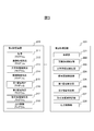
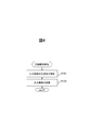
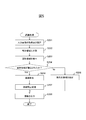
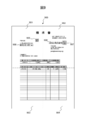
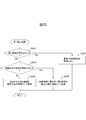
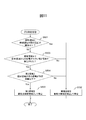
- FIG. 1 It is a figure which shows the schematic structure of the image processing system 1 according to an embodiment. It is a figure which shows an example of the data structure of an item table. It is a figure which shows the schematic structure of the 2nd storage device 210 and the 2nd processing circuit 220. It is a flowchart which shows the operation of an image reading process. It is a flowchart which shows the operation of a recognition process. It is a schematic diagram which shows an example of the input image 600. It is a flowchart which shows the example of the operation of the area identification processing. It is a schematic diagram which shows an example of the input image 800. It is a schematic diagram which shows an example of the input image 900. It is a flowchart which shows the example of the operation of the 1st specific processing.
- FIG. 1 is a diagram showing a schematic configuration of an image processing system 1 according to an embodiment. As shown in FIG. 1, the image processing system 1 includes an image reading device 100 and an information processing device 200.
- the image reading device 100 is, for example, a scanner device or the like.
- the image reading device 100 is connected to the information processing device 200.
- the information processing device 200 is an example of an image processing device, such as a personal computer.
- the image reading device 100 includes a first interface device 101, an imaging device 102, a first storage device 110, and a first processing circuit 120.
- the first interface device 101 has an interface circuit similar to a serial bus such as USB (Universal Serial Bus), and is electrically connected to the information processing device 200 to transmit and receive image data and various information. Further, instead of the first interface device 101, a communication device having an antenna for transmitting and receiving wireless signals and a wireless communication interface circuit for transmitting and receiving signals through a wireless communication line according to a predetermined communication protocol may be used. good.
- the predetermined communication protocol is, for example, a wireless LAN (Local Area Network).
- the image pickup device 102 has a reduction optical system type image pickup sensor including an image pickup element by CCD (Charge Coupled Device) arranged linearly in the main scanning direction. Further, the image pickup device 102 includes a light source that irradiates light, a lens that forms an image on the image pickup element, and an A / D conversion that amplifies an electric signal output from the image pickup element and performs analog / digital (A / D) conversion. Has a vessel. In the image pickup apparatus 102, the image pickup sensor images the conveyed medium to generate and output an analog image signal, and the A / D converter A / D-converts the analog image signal and digitally inputs it. Generate and output an image.
- CCD Charge Coupled Device
- the input image is a color multi-valued image in which each pixel data is composed of, for example, a total of 24 bits of R (red) value, G (green) value, and B (blue) value represented by 8 bits for each RGB color.
- a 1x optical system type CIS (Contact Image Sensor) equipped with a CMOS (Complementary Metal Oxide Semiconductor) image sensor may be used instead of the CCD.
- the first storage device 110 includes a memory device such as a RAM (RandomAccessMemory) and a ROM (ReadOnlyMemory), a fixed disk device such as a hard disk, or a portable storage device such as a flexible disk and an optical disk. Further, the first storage device 110 stores computer programs, databases, tables, etc. used for various processes of the image reading device 100.
- the computer program may be installed in the first storage device 110 from a computer-readable portable recording medium using a known setup program or the like.
- the portable recording medium is, for example, a CD-ROM (compact disk read only memory), a DVD-ROM (digital versatile disk read only memory), or the like.
- the first storage device 110 stores an input image or the like generated by the image pickup device 102.
- the first processing circuit 120 operates based on a program stored in advance in the first storage device 110.
- the first processing circuit 120 is, for example, a CPU (Control Processing Unit).
- a DSP digital signal processor
- an LSI large scale integration
- an ASIC Application Specific Integrated Circuit
- an FPGA Field-Programming Gate Array
- the first processing circuit 120 is connected to the first interface device 101, the image pickup device 102, the first storage device 110, and the like, and controls each of these parts.
- the first processing circuit 120 performs media reading control of the image pickup device 102, data transmission / reception control with the information processing device 200 via the first interface device 101, and the like.
- the information processing device 200 includes a second interface device 201, an input device 202, a display device 203, a second storage device 210, and a second processing circuit 220.
- a second interface device 201 an input device 202, a display device 203, a second storage device 210, and a second processing circuit 220.
- the second interface device 201 has an interface circuit similar to that of the first interface device 101 of the image reading device 100, and connects the information processing device 200 and the image reading device 100. Further, instead of the second interface device 201, a communication device having an antenna for transmitting and receiving wireless signals and a wireless communication interface circuit for transmitting and receiving signals through a wireless communication line according to a predetermined communication protocol such as a wireless LAN. It may be used.
- the input device 202 has an input device such as a keyboard and a mouse, and an interface circuit for acquiring a signal from the input device, and outputs a signal according to the operation of the user to the second processing circuit 220.
- the display device 203 is an example of an output unit.
- the display device 203 includes a display composed of a liquid crystal display, an organic EL (Electro-Luminescence), and the like, and an interface circuit for outputting image data to the display.
- the display device 203 displays various information on the display according to the instruction from the second processing circuit 220.
- the second storage device 210 is an example of a storage unit, and has a memory device, a fixed disk device, a portable storage device, and the like similar to the first storage device 110 of the image reading device 100.
- the second storage device 210 stores computer programs, databases, tables, and the like used for various processes of the information processing device 200.
- the computer program may be installed in the second storage device 210 from a computer-readable portable recording medium such as a CD-ROM or a DVD-ROM using a known setup program or the like.
- keywords related to the name of the business partner are stored in advance as data.
- the keyword related to the name of the business partner is a character that can be included in the name of the business partner, for example, a joint-stock company, a limited company, or the like. The details of the item table will be described later.
- the second processing circuit 220 operates based on a program stored in advance in the second storage device 210.
- the second processing circuit 220 is, for example, a CPU.
- a DSP, LSI, ASIC, FPGA, or the like may be used as the second processing circuit 220.
- the second processing circuit 220 is connected to the second interface device 201, the input device 202, the display device 203, the second storage device 210, and the like, and controls each of these parts.
- the second processing circuit 220 performs data transmission / reception control with the image reading device 100 via the second interface device 201, input control of the input device 202, display control of the display device 203, and the like.
- FIG. 2 is a diagram showing an example of the data structure of the item table.
- keywords and / or formats related to each item are stored in association with each of a plurality of items included in the form.
- the plurality of items include items other than the name of the business partner, such as a zip code, an address, a telephone number, a person in charge, an e-mail address, a bank account, a date and a document number.
- the keyword is a character that can be included in the character string indicating each item.
- the keyword for each item is an example of the second keyword.
- the format is the format of a character string indicating each item.
- FIG. 3 is a diagram showing a schematic configuration of the second storage device 210 and the second processing circuit 220.
- the second storage device 210 includes the acquisition program 211, the image area detection program 212, the character string area detection program 213, the candidate area detection program 214, the first area detection program 215, and the second area identification program 216. , The customer area identification program 217, the output control program 218, and the like are stored. Each of these programs is a functional module implemented by software running on the processor.
- the second processing circuit 220 reads each program stored in the second storage device 210 and operates according to each read program. As a result, the second processing circuit 220 includes the acquisition unit 221, the image area detection unit 222, the character string area detection unit 223, the candidate area detection unit 224, the first area detection unit 225, the second area identification unit 226, and the customer area. It functions as a specific unit 227 and an output control unit 228.
- FIG. 4 is a flowchart showing the operation of the image reading process by the image reading device 100.
- the operation of the image reading process will be described with reference to the flowchart shown in FIG.
- the operation flow described below is mainly executed by the first processing circuit 120 in cooperation with each element of the image reading device 100 based on the program stored in the first storage device 110 in advance.
- the image pickup device 102 captures a form such as an invoice, a notice, or a certificate including a seal or a logo as a manuscript, generates an input image, and stores the input image in the first storage device 110 (step S101). ..
- the first processing circuit 120 transmits the input image stored in the first storage device 110 to the information processing device 200 via the first interface device 101 (step S102), and ends a series of steps.
- FIG. 5 is a flowchart showing the operation of the recognition process by the information processing device 200.
- the operation of the recognition process will be described with reference to the flowchart shown in FIG.
- the operation flow described below is mainly executed by the second processing circuit 220 in cooperation with each element of the information processing device 200 based on the program stored in the second storage device 210 in advance.
- the acquisition unit 221 acquires the input image from the image reading device 100 via the second interface device 201 and stores it in the second storage device 210 (step S201).
- FIG. 6 is a schematic diagram showing an example of the input image 600.
- the input image 600 includes a seal 605, a zip code 606, an address 607, a company name 608, a telephone number 609, a business partner name 610, an address 611, a bank account 612, a bank account 613, and the like. include.
- the image area detection unit 222 divides the input image into a plurality of partial areas (step S202).
- the image area detection unit 222 divides, for example, an input image into a predetermined number in each of the vertical direction and / or the horizontal direction, and divides the input image into a plurality of partial areas.
- the input image 600 is divided into two in each of the vertical direction and the horizontal direction, and is divided into four partial regions 601 to 604.
- the information processing device 200 detects the name of the business partner based on the positional relationship with the image area including the seal or the logo in the input image in which the form is captured.
- the name of the business partner is described in any of the upper left part, the upper right part, the lower left part or the lower right part, and a seal or a logo is described in the vicinity thereof. Therefore, the information processing apparatus 200 divides the input image into two in the vertical direction and two in the horizontal direction so that the name of the business partner and the seal or logo are included in the same partial area. can do.
- the image area detection unit 222 detects the seal stamp area including the seal stamp or the logo area including the logo in the input image (step S203).
- the seal stamp area and the logo area may be collectively referred to as a graphic area.
- the graphic area is an example of an image area including a seal or a logo.
- the image area detection unit 222 detects a predetermined graphic area for each of a plurality of partial areas in the input image.
- the seal stamp area includes a red seal stamp area including a red seal stamp and / or a black seal stamp area including a black seal stamp.
- the image area detection unit 222 first converts the RGB (red, green, blue) values of each pixel in the input image into HSL (hue, saturation, luminance) values in order to detect the red stamp area. Next, the image area detection unit 222 includes pixels having a hue value less than the first threshold value (for example, 30) and pixels having a hue value larger than the second threshold value (for example, 330) (that is, pixels having orange to magenta). ) Is extracted. Next, the image area detection unit 222 calculates the total value of the value obtained by subtracting the G value from the R value and the value obtained by subtracting the B value from the R value as the red intensity for each extracted pixel. The image area detection unit 222 may use the S (saturation) value of each pixel as the red intensity for each extracted pixel.
- the image area detection unit 222 determines a pixel whose calculated red intensity is equal to or higher than the third threshold value (for example, 32) as a stamp pixel.
- the region including the region where the extracted stamp pixels are connected is detected as the red stamp region in which the stamp is captured.
- the image area detection unit 222 groups the areas surrounded by the stamp pixels adjacent to each other into one group by labeling to form a red stamp area in which the stamp is reflected.
- the image area detection unit 222 may detect only the group whose size (area) is within a predetermined range as the red stamp area.
- the predetermined range is preset to a range that can be taken by a general seal.
- the image area detection unit 222 may detect only a group having a predetermined shape as a red stamp area among the groups.
- the predetermined shape is preset to a shape that can be taken by a general stamp, such as a circle or a square.
- the image area detection unit 222 calculates a normalized cross-correlation value between each group and a predetermined shape, and detects the group as a red stamp region only when the calculated normalized cross-correlation value is equal to or more than a predetermined value. do.
- the image area detection unit 222 may detect the circumscribed rectangle of each group as the red stamp area.
- the image area detection unit 222 first converts the RGB value of each pixel in the input image into a YUV (luminance, color difference) value in order to detect the logo area or the black seal area that does not overlap with the character string. do. Next, the image area detection unit 222 extracts pixels whose luminance value is less than the fourth threshold value (for example, 128) as black pixels. Next, the image area detection unit 222 groups the areas surrounded by black pixels adjacent to each other into one group by labeling, and detects a group having a predetermined shape as a logo area or a black stamp area among the groups. The image area detection unit 222 may detect only the group whose size is within the predetermined range as the logo area or the black stamp area. Further, the image area detection unit 222 may detect the circumscribed rectangle of each group as a logo area or a black stamp area.
- the image area detection unit 222 sets the pixel position in the vertical direction in the input image as a class and determines the number of pixels of the black pixel at each pixel position in the vertical direction in order to detect the black seal area overlapping the character string. Generate a histogram to be the frequency.
- the number of continuous classes having a frequency of 5th threshold value (for example, 10) or more is within a predetermined range (for example, the number of pixels corresponding to 15 mm or more and the number of pixels corresponding to 30 mm or less).
- a certain vertical area is detected as a seal candidate line.
- characters are arranged in the horizontal direction, so that there is a margin between the lines in which the characters are written. However, in the area where the seal is pressed, the margin is removed because the seal exists between the lines. Therefore, it is highly possible that the seal is present in the region in the histogram where the classes having a certain degree of frequency are continuous to some extent.
- the image area detection unit 222 groups the areas surrounded by black pixels adjacent to each other into one group by labeling in the seal candidate line.
- the image area detection unit 222 detects a group having a size within a predetermined range and an aspect ratio within a predetermined aspect ratio range among the groups as a black stamp region.
- the predetermined range is set to a range of, for example, the number of pixels corresponding to 15 mm or more and the number of pixels corresponding to 30 mm or less.
- the aspect ratio range is set to, for example, 2/3 or more and 3/2 or less.
- the image area detection unit 222 may detect the circumscribed rectangle of each group as the black stamp area.
- the area including the seal stamp 605 is detected as a graphic area in the partial area 601.
- the image area detection unit 222 determines whether or not a graphic area is detected in the input image (step S204).
- the business partner area identification unit 227 uses the item name corresponding to the business partner name included in the input image and the positional relationship with respect to the item name from the input image.
- the customer area is detected (step S205).
- the business partner area is an area in the input image that includes a character string indicating the name of the business partner.
- the customer area identification unit 227 uses a known OCR (Optical Character Recognition) technology to detect characters from the input image and detect a plurality of characters having a first positional relationship as a character string.
- the plurality of characters having the first positional relationship are, for example, characters that overlap each other in the vertical direction and are adjacent to each other within a certain range in the horizontal direction and are continuous.
- the fixed range is set to, for example, the number of pixels corresponding to the margin.
- the business partner area identification unit 227 extracts a character string including an item name corresponding to the business partner name from the detected character strings.
- the item name corresponding to the name of the business partner is, for example, "company name” or the like.
- the business partner area identification unit 227 detects a character string having a second positional relationship with respect to the extracted character string as a character string indicating the name of the business partner.
- the second positional relationship includes a direction (for example, right side, lower side, lower right side) and a distance (for example, within a pixel corresponding to 30 mm) and is preset.
- the customer area identification unit 227 detects the area including the detected character string as the customer area.
- the customer area identification unit 227 detects, for example, the circumscribed rectangle of the detected character string as the customer area.
- the customer area identification unit 227 shifts the process to step S208.
- the character string area detection unit 223 removes the seal stamp component or the logo component from the input image (step S206).
- the character string region detection unit 223 When the red stamp region is detected in the input image, the character string region detection unit 223 first generates an expanded image in which the white component is expanded with respect to the input image, and the pixel value of each pixel in the expanded image ( R value, G value, B value) are determined as background information of each pixel in the corresponding input image. That is, the background information corresponding to the pixel of interest in the input image is set to the pixel value of the pixel having the highest brightness among the peripheral pixels of the pixel of interest. Next, the character string area detection unit 223 calculates the R value S r , G value S g , and B value S b of each pixel in the red stamp area according to the following equations (1) to (3), respectively.
- D r (B r- S r ) x (red proportion) + S r (1)
- D g (B g- S g ) x (red proportion) + S g (2)
- D b (B b- S b ) x (red proportion) + S b (3)
- the red color ratio is calculated by, for example, the following formula (4).
- (Red ratio) ⁇ (Red intensity of the pixel of interest) - ⁇ / ⁇ (4)
- ⁇ is a coefficient (for example, 96) and is preset based on the range width of the red intensity.
- ⁇ is an offset value (for example, 32) and is preset based on the range of red intensity.
- the red ratio is set within the range of 0 or more and 1 or less. That is, when the value calculated by the formula (4) is 0 or less, the red ratio is corrected to 0, and when the value calculated by the formula (4) is 1 or more, the red ratio is corrected to 1. ..
- the character string area detection unit 223 combines the pixel value of each pixel in the red stamp area with the background information of each pixel according to the red ratio of each pixel, thereby leaving the character component in the red stamp area. Only the components of the red seal can be satisfactorily removed.
- the character string area detection unit 223 When a logo area or a black stamp area that does not overlap with the character string is detected in the input image, the character string area detection unit 223 first exists in the vicinity of the logo area or the black stamp area and is close to white. Identify the pixel. The character string area detection unit 223 identifies pixels that are within a certain range from the logo area or the black stamp area and whose pixel values (R value, G value, B value) are at least a threshold value (for example, 200). The character string area detection unit 223 removes the stamp component or the logo component by replacing the pixel value of each pixel in the logo area or the black stamp area with the pixel value of the specified pixel.
- the character string area detection unit 223 does not remove the component of the black stamp for the black stamp area that overlaps with the character string in the input image.
- the second processing circuit 220 executes the area identification process (step S207).
- the area identification process the second processing circuit 220 specifies the customer area from the input image based on the positional relationship with the graphic area. The details of the area identification process will be described later.
- the output control unit 228 outputs information regarding the customer area detected in step S205 or the customer area specified in the area identification process in step S207 (step S208), and ends a series of steps. ..
- the output control unit 228 outputs by displaying the information regarding the business partner area on the display device 203.
- the output control unit 228 may output information about the business partner area by transmitting it to another information processing device via the second interface device 201.
- the output control unit 228 outputs, for example, a character string indicating the name of the business partner in the input image included in the business partner area as information regarding the business partner area.
- the output control unit 228 may output the input image and the position information indicating the coordinates of the business partner area in the input image as the information regarding the business partner area. Further, the output control unit 228 may output an image or the like cut out from the business partner area as information regarding the business partner area.
- step S206 may be omitted, and the second processing circuit 220 may specify the customer area without removing the seal stamp component or the logo component from the input image.
- FIG. 7 is a flowchart showing an example of the operation of the area identification process. The flow of the operation shown in FIG. 7 is executed in step S207 of the flowchart shown in FIG.
- steps S301 to S310 shown in the flowchart of FIG. 7 is executed for each partial area in which the graphic area is detected among the plurality of partial areas.
- steps S301 to S310 are executed only for the partial area 601 in which the graphic area including the seal stamp 605 is detected.
- the character string area detection unit 223 detects the character string area from the partial area to be processed of the input image (step S301).
- the character string area detection unit 223 detects characters from the input image by using a known OCR technique, and detects a plurality of characters having a first positional relationship as character strings.
- the character string area detection unit 223 detects an area including the detected character string as a character string area.
- the character string area detection unit 223 detects, for example, the circumscribing rectangle of the detected character string as the character string area.
- the area including the postal code 606, the address 607, the company name 608, the telephone number 609, the customer name 610, the address 611, the bank account 612, and the bank account 613 in the partial area 601 is a character. Detected as a column area.
- the candidate area detection unit 224 uses the name of the business partner from the character string areas detected by the character string area detection unit 223 based on the keyword related to the name of the business partner stored in the second storage device 210. (Step S302).
- the candidate area detection unit 224 detects as a candidate area a character string area including a keyword related to the name of the business partner among the detected character string areas.
- the keyword "Co., Ltd.” is included in the company name 608 and the business partner name 610, and the character string area including the company name 608 and the business partner name 610 is detected as a candidate area. Will be done.
- the first area detection unit 225 detects the first area from the character string areas detected by the character string area detection unit 223 based on the keyword or format for each item stored in the item table (Ste S303).
- the first area is an area including any item among the plurality of items stored in the item table.
- the first area detection unit 225 detects as the first area a character string area including a keyword related to any item or a character string area satisfying a format related to any item among the detected character string areas. ..
- a character string area including a postal code 606, an address 607, a telephone number 609, an address 611, a bank account 612, and a bank account 613 is detected as the first area.
- the second area identification unit 226 identifies the second area that was not detected as the candidate area or the first area from the character string areas detected by the character string area detection unit 223 (step S304).
- the second area identification unit 226 identifies the character string area that is not detected as a candidate area and is not detected as the first area among the detected character string areas as the second area.
- all the character string areas are detected as candidate areas or first areas, and the second area is not specified.
- FIG. 8 is a schematic diagram showing an example of the input image 800 including the second region.
- the input image 800 includes a seal 805, a date 806, a document number 807, a business partner name 808, a person in charge 809, an e-mail address 810, a zip code 811, an address 812, a telephone number 813, and the like. It has been.
- the input image 800 is divided into four partial areas 801 to 804, and the area including the seal stamp 805 is detected as a graphic area in the partial area 802. Further, in the partial area 802, an area including the date 806, the document number 807, the name of the business partner 808, the person in charge 809, the e-mail address 810, the zip code 811, the address 812, and the telephone number 813 is detected as the character string area. ..
- the customer name 808 does not include the keyword "Co., Ltd.”, and no candidate area is detected from the partial area 801. Further, a character string area including the date 806, the document number 807, the person in charge 809, the mail address 810, the zip code 811, the address 812, and the telephone number 813 is detected as the first area in the partial area 801. Therefore, the character string area including the name 808 of the business partner that is not detected as the candidate area and is not detected as the first area is specified as the second area.
- the customer area identification unit 227 determines whether or not the candidate area has been detected by the candidate area detection unit 224 (step S305).
- the customer area identification unit 227 executes the first specific process (step S306).
- the customer area specifying unit 227 identifies the most promising candidate area, which is the most promising candidate area in the partial area, based on the second area. The details of the first specific process will be described later.
- the customer area specifying unit 227 determines whether or not a plurality of candidate areas have been detected by the candidate area detecting unit 224 (step S307).
- the customer area specifying unit 227 executes the second specifying process (step S308).
- the customer area specifying unit 227 identifies the most promising candidate area based on the positional relationship between the candidate area and the second area. The details of the second specific process will be described later.
- the customer area identification unit 227 is selected from the plurality of candidate areas based on the distance from the graphic area.
- One of the most promising candidate regions is specified (step S309).
- the customer area identification unit 227 calculates the distance between each of all the graphic areas in the partial area for each of the plurality of candidate areas.
- the customer area identification unit 227 identifies a combination of end positions (upper left, lower left, upper right, or lower right) located closest to each other in the input image in the candidate area and the graphic area, and identifies the specified end position.
- the Euclidean distance between the regions (the number of pixels corresponding to the linear distance) is calculated as the distance between the regions.
- the customer area identification unit 227 calculates the Manhattan distance between the specified end positions (the sum of the absolute value of the difference in the horizontal coordinates and the absolute value of the difference in the coordinates in the vertical direction) as the distance between the areas. You may.
- the customer area identification unit 227 may calculate the Euclidean distance or the Manhattan distance between the positions of the center of gravity of each area as the distance between the areas. Further, in the customer area specifying unit 227, when the candidate area and the graphic area overlap (when the number of overlapping pixels is a predetermined number or more), the distance between the areas may be set to 0.
- the customer area specifying unit 227 specifies the graphic area having the shortest distance as the graphic area located closest to each candidate area for each of the plurality of candidate areas, and specifies the distance between the areas.
- the customer area identification unit 227 identifies the combination of the candidate area and the graphic area having the shortest distance between the specified candidate areas and the graphic area, and sets the candidate area related to the specified combination as the most promising candidate area. Identify as.
- the candidate area including the company name 608 and the candidate area including the business partner name 610 are detected, and the business partner name 610 having a small distance from the graphic area including the seal stamp 605 is included.
- the candidate area is identified as the most promising candidate area.
- the image processing system 1 When the image processing system 1 is used by a company that converts forms such as invoices received from a business partner into data, the image processing system 1 needs to specify and manage the name of the business partner. Such an invoice is likely to include the name of the company and the name of the business partner as the company name. However, it is possible that the seal or logo of the business partner is included in the vicinity of the name of the business partner who issues the form, and the seal or logo is not included in the vicinity of the name of the company to which the form is sent. Highly sexual. Therefore, when a plurality of candidate areas are detected, the image processing system 1 accurately detects the area including the name of the business partner by specifying the candidate area closer to the graphic area as the most promising candidate area. be able to. As a result, the image processing system 1 can prevent the image processing system 1 from erroneously detecting a name other than the business partner as the name of the business partner.
- the customer area specifying unit 227 determines whether or not the processing of steps S301 to S309 is completed for all the partial areas where the graphic area is detected (step S310). When the graphic area is detected and a partial area that has not been processed remains, the customer area specifying unit 227 returns the process to step S301 and repeats the processes of steps S301 to S309.
- the customer area specifying unit 227 determines whether or not the most promising candidate area is specified from any of the partial areas (step S311).
- the customer area identification unit 227 makes a transaction from the input image based on the item name corresponding to the name of the customer and the positional relationship from the item name.
- the destination region is detected (step S312), and a series of steps is completed.
- the customer area identification unit 227 detects the customer area from the input image in the same manner as in the process of step S205 of FIG.
- the business partner area specifying unit 227 identifies the business partner area from the specified most promising candidate area (step S313), and a series of steps. To finish.
- the customer area identification unit 227 determines the customer area based on the distance between each of the most promising candidate areas specified for each partial area in which the graphic area is detected and the graphic area corresponding to each of the most promising candidate areas. Identify.
- the graphic area corresponding to each of the most promising candidate areas is a graphic area that is included in the partial area including each of the most promising candidate areas and is located closest to each of the most promising candidate areas in the partial area.
- the customer area specifying unit 227 calculates the distances between all the graphic areas in the partial area for each of the most promising candidate areas in the same manner as in the process of step S309.
- the customer area specifying unit 227 identifies the graphic area having the shortest distance as the graphic area located closest to each of the most promising candidate areas for each of the most promising candidate areas, and specifies the distance between the areas.
- the customer area identification unit 227 identifies the combination of the most promising candidate area and the graphic area having the shortest distance between the identified combinations of the most promising candidate area and the graphic area, and the most promising candidate related to the specified combination. Specify the area as the trading partner area.
- the customer area specifying unit 227 sets the most promising candidate area having the shortest distance from the corresponding graphic area as the customer area among the most promising candidate areas specified for each partial area in which the graphic area is detected. Identify.
- the most promising candidate region including the name of the business partner 610 is detected in the partial region 601 and the most promising candidate region is not detected in the other subregions 602 to 604. Therefore, the most promising candidate area including the name 610 of the business partner is specified as the business partner area.
- FIG. 9 is a schematic diagram showing an example of an input image 900 including a plurality of most promising candidate regions.
- the input image 900 includes a business partner logo 905, a company name 906, a business partner seal 907, a business partner name 908, and the like.
- the input image 900 is divided into four subregions 901 to 904. Then, in the partial area 901, the area including the logo 905 of the business partner is detected as a graphic area, and the area including the company name 906 is detected as the most promising candidate area. Further, in the partial area 902, the area including the seal stamp 907 of the business partner is detected as the graphic area. The area including the customer name 908 is detected as the most promising candidate area.
- the distance between the most promising candidate area including the customer's name 908 and the graphic area including the customer's seal 907 is the distance between the most promising candidate area including the company's name 906 and the graphic area including the customer's logo 905. Less than the distance between. Therefore, the most promising candidate area including the name 908 of the business partner is specified as the business partner area.
- the logo of the business partner or the seal of the person in charge of the business partner may be included in the same partial area as the company's name. Even in such a case, the seal of the business partner is likely to be stamped near the name of the business partner, and the distance between the name of the business partner and the seal of the business partner is the company name and the logo of the business partner. Or it is likely to be smaller than the distance between the seal of the person in charge of the business partner.
- the image processing system 1 identifies the most promising candidate area close to the corresponding graphic area as the business partner area, so that the area including the name of the business partner is included. Can be detected with high accuracy. As a result, the image processing system 1 can prevent the image processing system 1 from erroneously detecting a name other than the business partner as the name of the business partner.
- FIG. 10 is a flowchart showing an example of the operation of the first specific process. The operation flow shown in FIG. 10 is executed in step S306 of the flowchart shown in FIG. 7.
- the customer area specifying unit 227 determines whether or not the second area is specified by the second area specifying unit 226 (step S401).
- the customer area specifying unit 227 does not specify the most promising candidate area from the partial area (step S402), and ends a series of steps.
- the customer area specifying unit 227 determines whether or not a plurality of second areas are specified by the second area specifying unit 226 (step S403).
- the customer area specifying unit 227 specifies the second area as the most promising candidate area (step). S404), the series of steps is completed.
- the candidate area is not detected and the second area including the name 808 of the business partner is specified, and this second area is specified as the most promising candidate area.
- the customer area identification unit 227 has a plurality of second regions based on the distance from the graphic region.
- One of the most promising candidate regions is specified (step S405), and a series of steps is completed.
- the customer area specifying unit 227 calculates the distance between each of all the graphic areas in the partial area for each of the plurality of second areas in the same manner as in the process of step S309 of FIG.
- the customer area specifying unit 227 specifies the graphic area having the shortest distance as the graphic area located closest to each second area for each of the plurality of second areas, and specifies the distance between the areas.
- the customer area specifying unit 227 specifies the combination of the second area and the graphic area having the smallest distance between the specified second areas and the graphic area, and sets the second area related to the specified combination to the maximum. Identify as a promising candidate area.
- the image processing system 1 accurately identifies the region including the name of the business partner by specifying the second region closer to the graphic region as the most promising candidate region. Can be detected. As a result, the image processing system 1 can prevent the image processing system 1 from erroneously detecting a name other than the business partner as the name of the business partner.
- the customer area specifying unit 227 identifies the customer area from the second area specified by the second area specifying unit 226.
- the customer area identification unit 227 corresponds to the specified second region.
- the second area having the shortest distance from the graphic area is specified as the customer area.
- the logo of the business partner or the seal of the person in charge of the business partner may be included in the same partial area as the company's name.
- the image processing system 1 specifies the second region close to the corresponding graphic region as the business partner region, thereby that of the business partner.
- the area containing the name can be detected with high accuracy.
- the image processing system 1 can prevent the image processing system 1 from erroneously detecting a name other than the business partner as the name of the business partner.
- FIG. 11 is a flowchart showing an example of the operation of the second specific process. The operation flow shown in FIG. 11 is executed in step S308 of the flowchart shown in FIG. 7.
- the customer area identification unit 227 determines whether or not the distance between the candidate area detected by the candidate area detection unit 224 and the graphic area located closest to the candidate area is equal to or less than the distance threshold value. Determine (step S501).
- the customer area specifying unit 227 calculates the distance between the candidate area and each of all the graphic areas in the partial area in the same manner as in the process of step S309 of FIG.
- the customer area identification unit 227 identifies the graphic area having the shortest distance as the graphic area located closest to the candidate area, and specifies the distance between the areas.
- the distance threshold is set to, for example, the number of pixels corresponding to a predetermined number of lines (for example, 5 lines).
- the customer area specifying unit 227 identifies the candidate area as the most promising candidate area (step S502), and ends a series of steps. do. That is, when a seal or logo exists in the vicinity of the name of the business partner including the keyword in the form, the area including the name of the business partner is specified as the most promising candidate area.
- the customer area specifying unit 227 determines whether or not there is a second area whose distance from the graphic area is smaller than that of the candidate area. Is determined (step S503). In the same manner as in the process of step S405 of FIG. 10, the customer area specifying unit 227 has a graphic area located closest to each second area and a graphic area located closest to each second area for each second area specified by the second area specifying unit 226. , Specify the distance between each second area and each graphic area.
- the customer area identification unit 227 When the distance calculated for any second region is smaller than the distance calculated for the candidate region in step S501, the customer area identification unit 227 considers that there is a second region whose distance from the graphic region is smaller than that of the candidate region. judge. On the other hand, in the customer area identification unit 227, when the distance calculated for the candidate area in step S501 is equal to or less than the distance calculated for all the second areas, the second area having a smaller distance from the graphic area than the candidate area is used. Judge that it does not exist.
- the customer area specifying unit 227 identifies the candidate area as the most promising candidate area (step S502), and ends a series of steps.
- FIG. 12 is a schematic diagram showing an example of the input image 1200 in which the candidate area is separated from the graphic area.
- the input image 1200 includes the seal stamp 1205 of the business partner, the name 1206 of the business partner, and the like.
- the input image 1200 is divided into four partial areas 1201 to 1204, and the area including the customer's seal 1205 is detected as a graphic area in the partial area 1202, and the area including the customer's name 1206 is detected as a candidate area. ..
- the partial area 1202 does not include any items other than the items stored in the item table, and the second area is not specified in the partial area 1202.
- the distance between the candidate area including the business partner name 1206 and the graphic area including the business partner's seal 1205 is larger than the distance threshold.
- the candidate area including the name of the business partner 1206 is specified as the most promising candidate area.
- the customer area specifying unit 227 determines whether or not the distance between the second area and the graphic area is equal to or less than a predetermined distance. (Step S504).
- the customer area identification unit 227 is the second area having the shortest distance from the graphic area located closest to the second area in the partial area, and the second area and the closest to the second area. Identify the distance to the graphic area located in.
- the customer area specifying unit 227 determines that the distance between the second area and the graphic area is less than or equal to the predetermined distance when the specified distance is less than or equal to the predetermined distance, and when the specified distance is larger than the predetermined distance, the third It is determined that the distance between the two areas and the graphic area is larger than the predetermined distance.
- the customer area specifying unit 227 identifies the candidate area as the most promising candidate area (step S502), and ends a series of steps. That is, even if the company name that does not include the keyword exists closer to the seal or logo than the company name that includes the keyword in the form, if the company name that does not include the keyword is far from the seal or logo, the keyword The area including the company name including is specified as the most promising candidate area.
- the customer area specifying unit 227 specifies the second area as the most promising candidate area (step S505) and ends a series of steps. ..
- the customer area identification unit 227 identifies the second area having the shortest distance from the nearest graphic area among the second areas in the partial area as the most promising candidate area.
- FIG. 13 is a schematic diagram showing an example of the input image 1300 in which the candidate area is separated from the graphic area.
- the input image 1300 includes the customer's seal 1305, the company's name 1306, the customer's name 1307, and the like.
- the input image 1300 is divided into four subregions 1301-1304. Then, in the partial area 1301, the area including the customer's seal 1305 is detected as a graphic area, the area including the company's name 1306 is specified as a candidate area, and the area including the customer's name 1307 is detected as the second area. Will be done.
- the distance between the candidate area including the company name 1306 and the graphic area including the customer's seal 1305 is larger than the distance threshold.
- the distance between the second area including the customer's name 1307 and the graphic area including the seal 1305 is smaller than the distance between the candidate area including the company's name 1306 and the graphic area including the seal 1305, and , It is less than a predetermined distance. Therefore, the second area including the name of the business partner 1307 is specified as the most promising candidate area.
- the image processing system 1 can accurately detect the area including the name of the business partner even when the name of the business partner does not include the keyword and the name of the company includes the keyword. As a result, the image processing system 1 can prevent the image processing system 1 from erroneously detecting a name other than the business partner as the name of the business partner.
- step S501 may be omitted.
- the customer area specifying unit 227 has a second area in which the distance from the graphic area is smaller than the distance between the candidate area and the graphic area and is equal to or less than a predetermined distance, regardless of the distance between the candidate area and the graphic area. Is specified as the customer area.
- the distance from the graphic area of the customer area specifying unit 227 is smaller than the distance between the candidate area and the graphic area and is equal to or less than the predetermined distance.
- the second region may be specified as the most promising candidate region.
- the customer area specifying unit 227 identifies the candidate area having the shortest distance from the nearest graphic area among the plurality of candidate areas.
- the customer area specifying unit 227 has a second area in which the distance from the graphic area is smaller than the specified candidate area and the distance between the second area and the graphic area is equal to or less than a predetermined distance, the first Identify two areas as the most promising candidates.
- the distance from the graphic region is smaller than the distance between the specified candidate region and the graphic region and is equal to or less than a predetermined distance
- the distance is the largest in the customer area specifying unit 227.
- the small second region is specified as the most promising candidate region.
- the information processing device 200 may collectively execute the recognition process and the area identification process without dividing the input image into a plurality of partial areas.
- the process of step S202 is omitted, and in step S203, the image area detection unit 222 detects the graphic area from the entire input image.
- the processes of steps S301 to S309 are executed for the entire input image, and the process of step S310 is omitted.
- the customer area identification unit 227 uses the most promising candidate area specified in step S309 of FIG. 7, steps S404 and S405 of FIG. 10, or steps S502 and S505 of FIG. 11 as the customer area. Identify.
- the information processing apparatus 200 may specify the business partner area without executing the detection of the first area and the specification of the second area. In that case, the processing of steps S303 to S304 in FIG. 7 is omitted.
- the business partner area identification unit 227 shifts the process to step S312, and based on the item name corresponding to the business partner name and the positional relationship from the item name, Detect the customer area from the input image.
- the customer area specifying unit 227 identifies the detected candidate area as the most promising candidate area.
- the customer area specifying unit 227 specifies the candidate area having the shortest distance from the corresponding graphic area as the customer area among the candidate areas specified for each partial area in which the graphic area is detected. do.
- the business partner area identification unit 227 may prioritize the most promising candidate area detected as the candidate area and specify it as the business partner area. In that case, the customer area identification unit 227 determines whether or not the most promising candidate area detected as the candidate area exists. When the most promising candidate area detected as a candidate area exists, the customer area identification unit 227 is the most promising candidate area having the shortest distance from the corresponding graphic area among the most promising candidate areas detected as the candidate area. Is specified as the customer area. On the other hand, when the most promising candidate area detected as the candidate area does not exist, the customer area specifying unit 227 has the smallest distance from the corresponding graphic area among the most promising candidate areas specified as the second area. Identify a promising candidate area as a business partner area.
- the customer area specifying unit 227 is a distance from the corresponding graphic area among the plurality of candidate areas. Identify the smallest candidate area as the trading partner area. Further, when a plurality of graphic areas are detected, a candidate area corresponding to each graphic area is not detected, and a second area corresponding to any of the graphic areas is specified, the customer area specifying unit 227 identifies the candidate area. The second area is specified as the customer area. In particular, when a plurality of second regions corresponding to each graphic region are specified, the customer area specifying unit 227 trades the second region having the shortest distance from the corresponding graphic region among the plurality of second regions. Specify as the destination area.
- the information processing apparatus 200 has one business partner based on the distance from the graphic area including the seal or logo when a plurality of candidate areas for the name of the business partner are detected based on the keyword. Identify the area. As a result, the information processing apparatus 200 can more accurately identify the area including the name of the business partner from the input image.
- the information processing device 200 no longer accepts the correction of the name of the business partner from the user using the input device 202, and it is possible to reduce the processing load of the processor in the process of handling the input image. Further, when the information processing device 200 transmits information regarding the name of the business partner to another information processing device, the information processing device 200 does not receive a request for correction of the name of the business partner from the other information processing device, and the information processing device 200 and the information processing device 200 It has become possible to reduce the amount of communication between other information processing devices.
- the image processing system 1 has made it possible to reduce the work load of the person in charge in a company that automates the form input work by using OCR and RPA (Robotic Process Automation) technology.
- OCR and RPA Robot Process Automation
- the image processing system 1 makes it possible to accurately identify the name of a business partner when automating operations such as payment requests by digitizing invoices and other forms, improving user convenience. It became possible.
- FIG. 14 is a block diagram showing a schematic configuration of the second processing circuit 230 in the information processing apparatus according to another embodiment.
- the second processing circuit 230 executes recognition processing instead of the second processing circuit 220.
- the second processing circuit 230 includes an acquisition circuit 231, an image area detection circuit 232, a character string area detection circuit 233, a candidate area detection circuit 234, a first area detection circuit 235, a second area identification circuit 236, and a customer area identification circuit 237. And an output control circuit 238 and the like.
- the acquisition circuit 231 is an example of the acquisition unit, and has the same function as the acquisition unit 221.
- the acquisition circuit 231 acquires the input image from the image reading device 100 via the second interface device 201 and stores it in the second storage device 210.
- the image area detection circuit 232 is an example of the image area detection unit, and has the same function as the image area detection unit 222.
- the image area detection circuit 232 reads an input image from the second storage device 210, detects a graphic area in the input image, and stores the detection result in the second storage device 210.
- the character string area detection circuit 233 is an example of the character string area detection unit, and has the same function as the character string area detection unit 223.
- the character string area detection circuit 233 reads the input image from the second storage device 210, detects the character string area from the input image, and stores the detection result in the second storage device 210.
- the candidate area detection circuit 234 is an example of the candidate area detection unit, and has the same function as the candidate area detection unit 224.
- the candidate area detection circuit 234 reads the detection result of the character string area and the keyword related to the name of the business partner from the second storage device 210, detects the candidate area from the character string area, and transmits the detection result to the second storage device 210. save.
- the first region detection circuit 235 is an example of the first region detection unit, and has the same function as the first region detection unit 225.
- the first area detection circuit 235 reads the detection result and the item table of the character string area from the second storage device 210, detects the first area from the character string area, and stores the detection result in the second storage device 210. ..
- the second area identification circuit 236 is an example of the second area identification unit, and has the same function as the second area identification unit 226.
- the second area identification circuit 236 reads the detection result of the character string area and the detection result of the first area from the second storage device 210, identifies the second area from the character string area, and stores the specific result in the second storage device. Save to 210.
- the customer area identification circuit 237 is an example of the customer area identification unit, and has the same function as the customer area identification unit 227.
- the customer area identification circuit 237 reads the detection result of the candidate area, the detection result of the first area, and the identification result of the second area from the second storage device 210, specifies the customer area, and sets the specific result as the second. Store in the storage device 210.
- the output control circuit 238 is an example of the output control unit, and has the same function as the output control unit 228.
- the output control circuit 238 reads the specific result of the customer area from the second storage device 210, and outputs information about the customer area to the display device 203.
- the information processing apparatus can more accurately identify the area including the name of the business partner from the input image even when the second processing circuit 230 is used.
- the embodiments are not limited to these.
- the division of functions between the image reading device 100 and the information processing device 200 is not limited to the example of the image processing system 1 shown in FIG. 1, and each part of the image reading device 100 and the information processing device 200 is divided into the image reading device 100 and the information processing device. Which of the 200 is arranged can be changed as appropriate.
- the image reading device 100 and the information processing device 200 may be configured by one device.
- the first storage device 110 of the image reading device 100 may store each program and each data stored in the second storage device 210 of the information processing device 200. Further, the first processing circuit 120 of the image reading device 100 may operate as each part realized by the second processing circuit 220 of the information processing device 200. Further, the image reading device 100 may have a processing circuit similar to that of the second processing circuit 230 of the information processing device 200.
- the image reading device 100 has a display device similar to the display device 203. Since the recognition process is executed by the image reading device 100, the process of transmitting and receiving the input image in steps S102 and S201 is omitted. Each process of steps S202 to S208 is executed by the first processing circuit 120 of the image reading device 100. The operation of these processes is the same as when executed by the second processing circuit 220 or the second processing circuit 230 of the information processing apparatus 200. In this case, the image reading device 100 operates as an image processing device.
- the first interface device 101 and the second interface device 201 are connected via a network such as the Internet, a telephone line network (including a mobile terminal line network and a general telephone line network), and an intranet. May be good.
- the first interface device 101 and the second interface device 201 are provided with a communication interface circuit of the network to be connected.
- a plurality of information processing devices are distributed and arranged on the network so that the image processing service can be provided in the form of cloud computing, and each information processing device cooperates to perform recognition processing and the like. You may share it.
- the image processing system 1 can efficiently perform recognition processing on the input images read by the plurality of image reading devices.
- Information processing device 210 2nd storage device 221 Acquisition unit 222 Image area detection unit 223 Character string area detection unit 224 Candidate area detection unit 225 1st area detection unit 226 2nd area identification unit 227 Customer area identification unit 228 Output control unit
Landscapes
- Engineering & Computer Science (AREA)
- Physics & Mathematics (AREA)
- General Physics & Mathematics (AREA)
- Multimedia (AREA)
- Theoretical Computer Science (AREA)
- Character Input (AREA)
- Character Discrimination (AREA)
- Information Retrieval, Db Structures And Fs Structures Therefor (AREA)
- Image Analysis (AREA)
Abstract
入力画像から取引先の名称が含まれる領域をより精度良く特定することが可能な画像処理装置、制御方法、制御プログラムを提供する。画像処理装置は、取引先の名称に関するキーワードを記憶する記憶部と、入力画像を取得する取得部と、入力画像内で印鑑又はロゴが含まれる画像領域を検出する画像領域検出部と、入力画像から文字列領域を検出する文字列領域検出部と、キーワードに基づいて、文字列領域の中から、取引先の名称が含まれる候補領域を検出する候補領域検出部と、候補領域検出部により複数の候補領域が検出された場合に、画像領域からの距離に基づいて、複数の候補領域の中から一つの取引先領域を特定する取引先領域特定部と、取引先領域に関する情報を出力する出力制御部と、を有する。
Description
本開示は、画像処理装置、制御方法及び制御プログラムに関し、特に、印鑑又はロゴが含まれる画像を処理する画像処理装置、制御方法及び制御プログラムに関する。
請求書等の帳票を担当者が手作業によりデータ化している会社では、膨大な数の帳票のデータ化が必要である場合に担当者の業務負担が大きくなるため、帳票のデータ化作業の効率化に対する要望が高まっている。一般に、担当者は、各帳票に記載された取引先に対して所定の業務を行う必要があるため、帳票のデータ化を行う画像処理装置には、担当者が取引先の名称をより精度良く特定できることが望まれている。
印影の近傍に存在する文字列をデータベースと照合することにより、印影と重なった文字列を推定する業務文書処理装置が開示されている(特許文献1)。この業務文書処理装置は、印影領域の近傍に存在し且つ一部の文字が印影領域によって不明確となっている文字情報を印影関連情報として抽出する。業務文書処理装置は、印影関連情報の属性を特定し、文字列候補を格納する取引先の情報を格納する取引先データベースを参照して、属性毎に分類された印影関連情報を基に、印影領域と重複して不明確となっている文字列を推定する。
画像処理装置では、入力画像から取引先の名称が含まれる領域をより精度良く特定することが求められている。
画像処理装置、制御方法及び制御プログラムの目的は、入力画像から取引先の名称が含まれる領域をより精度良く特定することを可能とすることにある。
実施形態の一側面に係る画像処理装置は、取引先の名称に関するキーワードを記憶する記憶部と、入力画像を取得する取得部と、入力画像内で印鑑又はロゴが含まれる画像領域を検出する画像領域検出部と、入力画像から文字列領域を検出する文字列領域検出部と、キーワードに基づいて、文字列領域の中から、取引先の名称が含まれる候補領域を検出する候補領域検出部と、候補領域検出部により複数の候補領域が検出された場合に、画像領域からの距離に基づいて、複数の候補領域の中から一つの取引先領域を特定する取引先領域特定部と、取引先領域に関する情報を出力する出力制御部と、を有する。
また、実施形態の一側面に係る制御方法は、記憶部を有する画像処理装置の制御方法であって、画像処理装置が、取引先の名称に関するキーワードを記憶部に記憶し、入力画像を取得し、入力画像内で印鑑又はロゴが含まれる画像領域を検出し、入力画像から文字列領域を検出し、キーワードに基づいて、文字列領域の中から、取引先の名称が含まれる候補領域を検出し、複数の候補領域が検出された場合に、画像領域からの距離に基づいて、複数の候補領域の中から一つの取引先領域を特定し、取引先領域に関する情報を出力する。
また、実施形態の一側面に係る制御プログラムは、記憶部を有するコンピュータの制御プログラムであって、取引先の名称に関するキーワードを記憶部に記憶し、入力画像を取得し、入力画像内で印鑑又はロゴが含まれる画像領域を検出し、入力画像から文字列領域を検出し、キーワードに基づいて、文字列領域の中から、取引先の名称が含まれる候補領域を検出し、複数の候補領域が検出された場合に、画像領域からの距離に基づいて、複数の候補領域の中から一つの取引先領域を特定し、取引先領域に関する情報を出力することをコンピュータに実行させる。
本実施形態によれば、画像処理装置、制御方法及び制御プログラムは、入力画像から取引先の名称が含まれる領域をより精度良く特定することが可能となる。
本発明の目的及び効果は、特に請求項において指摘される構成要素及び組み合わせを用いることによって認識され且つ得られるだろう。前述の一般的な説明及び後述の詳細な説明の両方は、例示的及び説明的なものであり、特許請求の範囲に記載されている本発明を制限するものではない。
以下、本開示の一側面に係る画像処理装置、制御方法及び制御プログラムについて図を参照しつつ説明する。但し、本発明の技術的範囲はそれらの実施の形態に限定されず、特許請求の範囲に記載された発明とその均等物に及ぶ点に留意されたい。
図1は、実施形態に従った画像処理システム1の概略構成を示す図である。図1に示すように、画像処理システム1は、画像読取装置100と、情報処理装置200とを有する。
画像読取装置100は、例えばスキャナ装置等である。画像読取装置100は、情報処理装置200に接続されている。情報処理装置200は、画像処理装置の一例であり、例えばパーソナルコンピュータ等である。
画像読取装置100は、第1インタフェース装置101と、撮像装置102と、第1記憶装置110と、第1処理回路120とを有する。
第1インタフェース装置101は、USB(Universal Serial Bus)等のシリアルバスに準じるインタフェース回路を有し、情報処理装置200と電気的に接続して画像データ及び各種の情報を送受信する。また、第1インタフェース装置101の代わりに、無線信号を送受信するアンテナと、所定の通信プロトコルに従って、無線通信回線を通じて信号の送受信を行うための無線通信インタフェース回路とを有する通信装置が用いられてもよい。所定の通信プロトコルは、例えば無線LAN(Local Area Network)である。
撮像装置102は、主走査方向に直線状に配列されたCCD(Charge Coupled Device)による撮像素子を備える縮小光学系タイプの撮像センサを有する。さらに、撮像装置102は、光を照射する光源と、撮像素子上に像を結ぶレンズと、撮像素子から出力された電気信号を増幅してアナログ/デジタル(A/D)変換するA/D変換器とを有する。撮像装置102において、撮像センサは、搬送される媒体を撮像してアナログの画像信号を生成して出力し、A/D変換器は、このアナログの画像信号をA/D変換してデジタルの入力画像を生成して出力する。入力画像は、各画素データが、例えばRGB各色毎に8bitで表される計24bitのR(赤色)値、G(緑色)値、B(青色)値からなるカラー多値画像である。なお、CCDの代わりにCMOS(Complementary Metal Oxide Semiconductor)による撮像素子を備える等倍光学系タイプのCIS(Contact Image Sensor)が用いられてもよい。
第1記憶装置110は、RAM(Random Access Memory)、ROM(Read Only Memory)等のメモリ装置、ハードディスク等の固定ディスク装置、又はフレキシブルディスク、光ディスク等の可搬用の記憶装置等を有する。また、第1記憶装置110には、画像読取装置100の各種処理に用いられるコンピュータプログラム、データベース、テーブル等が格納される。コンピュータプログラムは、コンピュータ読み取り可能な可搬型記録媒体から公知のセットアッププログラム等を用いて第1記憶装置110にインストールされてもよい。可搬型記録媒体は、例えばCD-ROM(compact disk read only memory)、DVD-ROM(digital versatile disk read only memory)等である。また、第1記憶装置110は、撮像装置102により生成された入力画像等を記憶する。
第1処理回路120は、予め第1記憶装置110に記憶されているプログラムに基づいて動作する。第1処理回路120は、例えばCPU(Control Processing Unit)である。なお、第1処理回路120として、DSP(digital signal processor)、LSI(large scale integration)、ASIC(Application Specific Integrated Circuit)、FPGA(Field-Programming Gate Array)等が用いられてもよい。
第1処理回路120は、第1インタフェース装置101、撮像装置102及び第1記憶装置110等と接続され、これらの各部を制御する。第1処理回路120は、撮像装置102の媒体読取制御、第1インタフェース装置101を介した情報処理装置200とのデータ送受信制御等を行う。
情報処理装置200は、第2インタフェース装置201と、入力装置202と、表示装置203と、第2記憶装置210と、第2処理回路220とを有する。以下、情報処理装置200の各部について詳細に説明する。
第2インタフェース装置201は、画像読取装置100の第1インタフェース装置101と同様のインタフェース回路を有し、情報処理装置200と画像読取装置100とを接続する。また、第2インタフェース装置201の代わりに、無線信号を送受信するアンテナと、無線LAN等の所定の通信プロトコルに従って、無線通信回線を通じて信号の送受信を行うための無線通信インタフェース回路とを有する通信装置が用いられてもよい。
入力装置202は、キーボード、マウス等の入力装置及び入力装置から信号を取得するインタフェース回路を有し、利用者の操作に応じた信号を第2処理回路220に出力する。
表示装置203は、出力部の一例である。表示装置203は、液晶、有機EL(Electro-Luminescence)等から構成されるディスプレイ及びディスプレイに画像データを出力するインタフェース回路を有する。表示装置203は、第2処理回路220からの指示に従って、各種の情報をディスプレイに表示する。
第2記憶装置210は、記憶部の一例であり、画像読取装置100の第1記憶装置110と同様のメモリ装置、固定ディスク装置、可搬用の記憶装置等を有する。第2記憶装置210には、情報処理装置200の各種処理に用いられるコンピュータプログラム、データベース、テーブル等が格納される。コンピュータプログラムは、例えばCD-ROM、DVD-ROM等のコンピュータ読み取り可能な可搬型記録媒体から、公知のセットアッププログラム等を用いて第2記憶装置210にインストールされてもよい。
また、第2記憶装置210には、データとして、取引先の名称に関するキーワード、及び、項目テーブル等が予め記憶される。取引先の名称に関するキーワードは、取引先の名称に含まれ得る文字であり、例えば株式会社、有限会社等である。項目テーブルの詳細については後述する。
第2処理回路220は、予め第2記憶装置210に記憶されているプログラムに基づいて動作する。第2処理回路220は、例えばCPUである。なお、第2処理回路220として、DSP、LSI、ASIC、FPGA等が用いられてもよい。
第2処理回路220は、第2インタフェース装置201、入力装置202、表示装置203及び第2記憶装置210等と接続され、これらの各部を制御する。第2処理回路220は、第2インタフェース装置201を介した画像読取装置100とのデータ送受信制御、入力装置202の入力制御、表示装置203の表示制御等を行う。
図2は、項目テーブルのデータ構造の一例を示す図である。
項目テーブルには、帳票に含まれる複数の項目毎に、各項目に関するキーワード及び/又はフォーマット等が関連付けて記憶される。複数の項目には、郵便番号、住所、電話番号、担当者、メールアドレス、銀行口座、日付及び文書番号等の、取引先の名称以外の項目が含まれる。キーワードは、各項目を示す文字列に含まれ得る文字である。各項目に関するキーワードは、第2キーワードの一例である。フォーマットは、各項目を示す文字列の書式である。例えば、項目が郵便番号である場合、フォーマットとして「〒」、「数字3桁」、「-」、「数字4桁」の組合せが設定され、項目が電話番号である場合、フォーマットとして「数字2桁」、「-」、「数字4桁」、「-」、「数字4桁」の組合せ等が設定される。
図3は、第2記憶装置210及び第2処理回路220の概略構成を示す図である。
図3に示すように第2記憶装置210には、取得プログラム211、画像領域検出プログラム212、文字列領域検出プログラム213、候補領域検出プログラム214、第1領域検出プログラム215、第2領域特定プログラム216、取引先領域特定プログラム217及び出力制御プログラム218等の各プログラムが記憶される。これらの各プログラムは、プロセッサ上で動作するソフトウェアにより実装される機能モジュールである。第2処理回路220は、第2記憶装置210に記憶された各プログラムを読み取り、読み取った各プログラムに従って動作する。これにより、第2処理回路220は、取得部221、画像領域検出部222、文字列領域検出部223、候補領域検出部224、第1領域検出部225、第2領域特定部226、取引先領域特定部227及び出力制御部228として機能する。
図4は、画像読取装置100による画像読取処理の動作を示すフローチャートである。以下、図4に示したフローチャートを参照しつつ、画像読取処理の動作を説明する。なお、以下に説明する動作のフローは、予め第1記憶装置110に記憶されているプログラムに基づき主に第1処理回路120により画像読取装置100の各要素と協働して実行される。
最初に、撮像装置102は、原稿として、印鑑又はロゴが含まれる請求書、通知書又は証明書等の帳票を撮像して入力画像を生成し、第1記憶装置110に保存する(ステップS101)。
次に、第1処理回路120は、第1記憶装置110に保存された入力画像を、第1インタフェース装置101を介して情報処理装置200に送信し(ステップS102)、一連のステップを終了する。
図5は、情報処理装置200による認識処理の動作を示すフローチャートである。以下、図5に示したフローチャートを参照しつつ、認識処理の動作を説明する。なお、以下に説明する動作のフローは、予め第2記憶装置210に記憶されているプログラムに基づき主に第2処理回路220により情報処理装置200の各要素と協同して実行される。
最初に、取得部221は、入力画像を、第2インタフェース装置201を介して画像読取装置100から取得し、第2記憶装置210に保存する(ステップS201)。
図6は、入力画像600の一例を示す模式図である。
図6に示すように、入力画像600には、印鑑605、郵便番号606、住所607、自社の名称608、電話番号609、取引先の名称610、住所611、銀行口座612及び銀行口座613等が含まれている。
次に、画像領域検出部222は、入力画像を複数の部分領域に分割する(ステップS202)。画像領域検出部222は、例えば入力画像を垂直方向及び/又は水平方向にそれぞれ所定数ずつに分割し、複数の部分領域に分割する。
図6に示す例では、入力画像600は、垂直方向及び水平方向にそれぞれ二つずつに分割され、四つの部分領域601~604に分割されている。情報処理装置200は、帳票が撮像された入力画像内で印鑑又はロゴが含まれる画像領域との位置関係に基づいて、取引先の名称を検出する。一般的な帳票において、取引先の名称は、左上部、右上部、左下部又は右下部の何れかに記載され、その近傍には、印鑑又はロゴが記載されている。したがって、情報処理装置200は、入力画像を垂直方向及び水平方向に二つずつに分割することにより、取引先の名称と印鑑又はロゴとが同一の部分領域に含まれるように、入力画像を分割することができる。
次に、画像領域検出部222は、入力画像内で、印鑑が含まれる印鑑領域、又は、ロゴが含まれるロゴ領域を検出する(ステップS203)。以下では、印鑑領域及びロゴ領域を総じて図形領域と称する場合がある。図形領域は、印鑑又はロゴが含まれる画像領域の一例である。画像領域検出部222は、入力画像内の複数の部分領域毎に、所定図形領域を検出する。印鑑領域には、赤色の印鑑が含まれる赤色印鑑領域、及び/又は、黒色の印鑑が含まれる黒色印鑑領域が含まれる。
画像領域検出部222は、赤色印鑑領域を検出するために、まず、入力画像内の各画素のRGB(赤色、緑色、青色)値をHSL(色相、彩度、輝度)値に変換する。次に、画像領域検出部222は、色相値が第1閾値(例えば30)未満である画素と、色相値が第2閾値(例えば330)より大きい画素(即ち、オレンジ色から赤紫色を有する画素)を抽出する。次に、画像領域検出部222は、抽出した各画素について、R値からG値を減算した値と、R値からB値を減算した値との合計値を赤色強度として算出する。なお、画像領域検出部222は、抽出した各画素について、各画素のS(彩度)値を赤色強度として使用してもよい。
次に、画像領域検出部222は、算出した赤色強度が第3閾値(例えば32)以上である画素を印鑑画素に決定する。次に、入力画像内で、抽出した印鑑画素が連結する領域を含む領域を、印鑑が写っている赤色印鑑領域として検出する。画像領域検出部222は、相互に隣接する印鑑画素で囲まれる領域をラベリングにより一つのグループとしてまとめて印鑑が写っている赤色印鑑領域とする。なお、画像領域検出部222は、各グループの内、サイズ(面積)が所定範囲内であるグループのみを赤色印鑑領域として検出してもよい。所定範囲は、一般的な印鑑が取り得る範囲に予め設定される。また、画像領域検出部222は、各グループの内、所定形状を有するグループのみを赤色印鑑領域として検出してもよい。所定形状は、丸、四角等、一般的な印鑑が取り得る形状に予め設定される。例えば、画像領域検出部222は、各グループと所定形状との正規化相互相関値を算出し、算出した正規化相互相関値が所定値以上である場合に限り、そのグループを赤色印鑑領域として検出する。また、画像領域検出部222は、各グループの外接矩形を赤色印鑑領域として検出してもよい。
また、画像領域検出部222は、ロゴ領域、又は、文字列と重なっていない黒色印鑑領域を検出するために、まず、入力画像内の各画素のRGB値をYUV(輝度、色差)値に変換する。次に、画像領域検出部222は、輝度値が第4閾値(例えば128)未満である画素を黒色画素として抽出する。次に、画像領域検出部222は、相互に隣接する黒色画素で囲まれる領域をラベリングにより一つのグループとしてまとめ、各グループの内、所定形状を有するグループをロゴ領域又は黒色印鑑領域として検出する。なお、画像領域検出部222は、各グループの内、サイズが所定範囲内であるグループのみをロゴ領域又は黒色印鑑領域として検出してもよい。また、画像領域検出部222は、各グループの外接矩形をロゴ領域又は黒色印鑑領域として検出してもよい。
また、画像領域検出部222は、文字列と重なっている黒色印鑑領域を検出するために、入力画像内の垂直方向の画素位置を階級とし、垂直方向の各画素位置における黒色画素の画素数を度数とするヒストグラムを生成する。画像領域検出部222は、度数が第5閾値(例えば10)以上である階級が連続する連続数が所定範囲内(例えば15mmに相当する画素数以上であり且つ30mmに相当する画素数以下)である垂直方向の領域を印鑑候補行として検出する。一般に、横書きの帳票では、文字は横方向に並ぶため、文字が記載されている行間には余白が存在する。しかしながら、印鑑が押下された領域では、行間に印鑑が存在するため、余白が除去される。したがって、ヒストグラム内で度数がある程度の大きさを有する階級がある程度連続している領域には印鑑が存在する可能性が高い。
次に、画像領域検出部222は、印鑑候補行内で、相互に隣接する黒色画素で囲まれる領域をラベリングにより一つのグループとしてまとめる。画像領域検出部222は、各グループの内、サイズが所定範囲内であり且つアスペクト比が所定のアスペクト比範囲内であるグループを黒色印鑑領域として検出する。所定範囲は、例えば15mmに相当する画素数以上であり且つ30mmに相当する画素数以下の範囲に設定される。アスペクト比範囲は、例えば2/3以上且つ3/2以下に設定される。また、画像領域検出部222は、各グループの外接矩形を黒色印鑑領域として検出してもよい。
図6に示す例では、部分領域601内で印鑑605を含む領域が図形領域として検出される。
次に、画像領域検出部222は、入力画像内で図形領域が検出されたか否かを判定する(ステップS204)。
入力画像内で図形領域が検出されなかった場合、取引先領域特定部227は、入力画像に含まれる、取引先の名称に対応する項目名及びその項目名に対する位置関係に基づいて、入力画像から取引先領域を検出する(ステップS205)。取引先領域は、入力画像内で取引先の名称を示す文字列が含まれる領域である。取引先領域特定部227は、公知のOCR(Optical Character Recognition)技術を利用して、入力画像から文字を検出し、第1位置関係を有する複数の文字を文字列として検出する。第1位置関係を有する複数の文字は、例えば垂直方向において相互に重複し、且つ、水平方向において一定範囲内で隣り合いつつ連続する文字である。一定範囲は、例えば余白に相当する画素数に設定される。取引先領域特定部227は、検出した文字列の内、取引先の名称に対応する項目名を含む文字列を抽出する。取引先の名称に対応する項目名は、例えば「会社名」等である。
取引先領域特定部227は、抽出した文字列に対して第2位置関係を有する文字列を、取引先の名称を示す文字列として検出する。第2位置関係は、方向(例えば右側、下側、右下側)及び距離(例えば30mmに相当する画素内)を含み、事前に設定される。取引先領域特定部227は、検出した文字列を含む領域を取引先領域として検出する。取引先領域特定部227は、例えば検出した文字列の外接矩形を取引先領域として検出する。次に、取引先領域特定部227は、処理をステップS208に移行する。
一方、入力画像内で図形領域が検出された場合、文字列領域検出部223は、入力画像から印鑑成分又はロゴ成分を除去する(ステップS206)。
入力画像内で赤色印鑑領域が検出された場合、文字列領域検出部223は、まず、入力画像に対して白色成分を膨張させた膨張画像を生成し、膨張画像内の各画素の画素値(R値、G値、B値)を、対応する入力画像内の各画素の背景情報として決定する。即ち、入力画像内の注目画素に対応する背景情報は、注目画素の周辺画素の中で輝度が最も高い画素の画素値に設定される。次に、文字列領域検出部223は、赤色印鑑領域内の各画素のR値Sr、G値Sg、B値Sbを、それぞれ以下の式(1)~(3)に従って算出されるDr、Dg、Dbに変換する。
Dr=(Br-Sr)×(赤色割合)+Sr (1)
Dg=(Bg-Sg)×(赤色割合)+Sg (2)
Db=(Bb-Sb)×(赤色割合)+Sb (3)
Dr=(Br-Sr)×(赤色割合)+Sr (1)
Dg=(Bg-Sg)×(赤色割合)+Sg (2)
Db=(Bb-Sb)×(赤色割合)+Sb (3)
赤色割合は、例えば以下の式(4)により算出される。
(赤色割合)={(注目画素の赤色強度)-β}/α (4)
ここで、αは係数(例えば96)であり、赤色強度の値域幅に基づいて、予め設定される。また、βはオフセット値(例えば32)であり、赤色強度の値域に基づいて、予め設定される。赤色割合は、0以上であり且つ1以下である範囲内に設定される。即ち、式(4)により算出された値が0以下である場合、赤色割合は0に補正され、式(4)により算出された値が1以上である場合、赤色割合は1に補正される。
(赤色割合)={(注目画素の赤色強度)-β}/α (4)
ここで、αは係数(例えば96)であり、赤色強度の値域幅に基づいて、予め設定される。また、βはオフセット値(例えば32)であり、赤色強度の値域に基づいて、予め設定される。赤色割合は、0以上であり且つ1以下である範囲内に設定される。即ち、式(4)により算出された値が0以下である場合、赤色割合は0に補正され、式(4)により算出された値が1以上である場合、赤色割合は1に補正される。
文字列領域検出部223は、赤色印鑑領域内の各画素の画素値を、各画素の赤色割合に応じて各画素の背景情報と合成させることにより、赤色印鑑領域において、文字の成分を残しつつ赤色印鑑の成分のみを良好に除去することができる。
入力画像内でロゴ領域、又は、文字列と重なっていない黒色印鑑領域が検出された場合、文字列領域検出部223は、まず、そのロゴ領域又は黒色印鑑領域の周辺に存在し且つ白色に近い画素を特定する。文字列領域検出部223は、そのロゴ領域又は黒色印鑑領域から一定範囲内であり且つ画素値(R値、G値、B値)が閾値(例えば200)以上である画素を特定する。文字列領域検出部223は、そのロゴ領域又は黒色印鑑領域内の各画素の画素値を特定した画素の画素値に置換することにより、印鑑成分又はロゴ成分を除去する。
また、文字列領域検出部223は、入力画像内で文字列と重なっている黒色印鑑領域については黒色印鑑の成分を除去しない。
次に、第2処理回路220は、領域特定処理を実行する(ステップS207)。領域特定処理において、第2処理回路220は、図形領域との位置関係に基づいて、入力画像から取引先領域を特定する。領域特定処理の詳細については後述する。
次に、出力制御部228は、ステップS205で検出された取引先領域、又は、ステップS207の領域特定処理で特定された取引先領域に関する情報を出力し(ステップS208)、一連のステップを終了する。出力制御部228は、取引先領域に関する情報を表示装置203に表示することにより出力する。なお、出力制御部228は、取引先領域に関する情報を、第2インタフェース装置201を介して他の情報処理装置に送信することにより出力してもよい。出力制御部228は、取引先領域に関する情報として、例えば取引先領域に含まれる、入力画像内で取引先の名称を示す文字列を出力する。なお、出力制御部228は、取引先領域に関する情報として、入力画像及び入力画像内の取引先領域の座標を示す位置情報を出力してもよい。また、出力制御部228は、取引先領域に関する情報として、取引先領域を切り出した画像等を出力してもよい。
なお、ステップS206の処理が省略され、第2処理回路220は、入力画像から印鑑成分又はロゴ成分を除去せずに、取引先領域を特定してもよい。
図7は、領域特定処理の動作の例を示すフローチャートである。図7に示す動作のフローは、図5に示すフローチャートのステップS207において実行される。
図7のフローチャートに示すステップS301~S310の処理は、複数の部分領域の内、図形領域が検出された部分領域毎に実行される。
図6に示す例では、印鑑605を含む図形領域が検出された部分領域601に対してのみ、ステップS301~S310の処理が実行される。
最初に、文字列領域検出部223は、入力画像の処理対象の部分領域から文字列領域を検出する(ステップS301)。文字列領域検出部223は、公知のOCR技術を利用して、入力画像から文字を検出し、第1位置関係を有する複数の文字を文字列として検出する。文字列領域検出部223は、検出した文字列を含む領域を文字列領域として検出する。文字列領域検出部223は、例えば検出した文字列の外接矩形を文字列領域として検出する。
図6に示す例では、部分領域601内で郵便番号606、住所607、自社の名称608、電話番号609、取引先の名称610、住所611、銀行口座612及び銀行口座613をそれぞれ含む領域が文字列領域として検出される。
次に、候補領域検出部224は、第2記憶装置210に記憶された取引先の名称に関するキーワードに基づいて、文字列領域検出部223により検出された文字列領域の中から、取引先の名称が含まれる候補領域を検出する(ステップS302)。候補領域検出部224は、検出された文字列領域の内、取引先の名称に関するキーワードが含まれる文字列領域を候補領域として検出する。
図6に示す例では、自社の名称608及び取引先の名称610にキーワード「株式会社」が含まれており、自社の名称608及び取引先の名称610をそれぞれ含む文字列領域が候補領域として検出される。
次に、第1領域検出部225は、項目テーブルに記憶された各項目に関するキーワード又はフォーマットに基づいて、文字列領域検出部223により検出された文字列領域の中から第1領域を検出する(ステップS303)。第1領域は、項目テーブルに記憶された複数の項目の内の何れかの項目が含まれる領域である。第1領域検出部225は、検出された文字列領域の内、何れかの項目に関するキーワードが含まれる文字列領域、又は、何れかの項目に関するフォーマットを満たす文字列領域を第1領域として検出する。
図6に示す例では、郵便番号606、住所607、電話番号609、住所611、銀行口座612及び銀行口座613をそれぞれ含む文字列領域が第1領域として検出される。
次に、第2領域特定部226は、文字列領域検出部223により検出された文字列領域の中から、候補領域又は第1領域として検出されなかった第2領域を特定する(ステップS304)。第2領域特定部226は、検出された文字列領域の内、候補領域として検出されず且つ第1領域として検出されなかった文字列領域を第2領域として特定する。
図6に示す例では、全ての文字列領域が候補領域又は第1領域として検出されており、第2領域は特定されない。
図8は、第2領域が含まれる入力画像800の一例を示す模式図である。
図8に示すように、入力画像800には、印鑑805、日付806、文書番号807、取引先の名称808、担当者809、メールアドレス810、郵便番号811、住所812及び電話番号813等が含まれている。入力画像800は四つの部分領域801~804に分割され、部分領域802内で印鑑805を含む領域が図形領域として検出される。また、部分領域802内で日付806、文書番号807、取引先の名称808、担当者809、メールアドレス810、郵便番号811、住所812及び電話番号813をそれぞれ含む領域が文字列領域として検出される。取引先の名称808にはキーワード「株式会社」が含まれておらず、部分領域801から候補領域は検出されない。また、部分領域801内で日付806、文書番号807、担当者809、メールアドレス810、郵便番号811、住所812及び電話番号813それぞれ含む文字列領域が第1領域として検出される。したがって、候補領域として検出されず且つ第1領域として検出されなかった取引先の名称808を含む文字列領域が、第2領域として特定される。
次に、取引先領域特定部227は、候補領域検出部224により候補領域が検出されたか否かを判定する(ステップS305)。
候補領域検出部224により候補領域が検出されなかった場合、取引先領域特定部227は、第1特定処理を実行する(ステップS306)。第1特定処理において、取引先領域特定部227は、第2領域に基づいて、部分領域内で最も有力な候補領域である最有力候補領域を特定する。第1特定処理の詳細については後述する。
一方、候補領域が検出された場合、取引先領域特定部227は、候補領域検出部224により複数の候補領域が検出されたか否かを判定する(ステップS307)。
複数の候補領域が検出されなかった場合、即ち検出された候補領域の数が一つである場合、取引先領域特定部227は、第2特定処理を実行する(ステップS308)。第2特定処理において、取引先領域特定部227は、候補領域と第2領域の位置関係に基づいて最有力候補領域を特定する。第2特定処理の詳細については後述する。
一方、複数の候補領域が検出された場合、即ち検出された候補領域の数が複数である場合、取引先領域特定部227は、図形領域からの距離に基づいて、複数の候補領域の中から一つの最有力候補領域を特定する(ステップS309)。
取引先領域特定部227は、複数の候補領域毎に、部分領域内の全ての図形領域のそれぞれとの間の距離を算出する。取引先領域特定部227は、候補領域と図形領域において、入力画像内で相互に最も近くに位置する端部位置(左上、左下、右上又は右下)の組合せを特定し、特定した端部位置間のユークリッド距離(直線距離に相当する画素数)を領域間の距離として算出する。なお、取引先領域特定部227は、領域間の距離として、特定した端部位置間のマンハッタン距離(水平方向の座標の差の絶対値と垂直方向の座標の差の絶対値の合計)を算出してもよい。また、取引先領域特定部227は、領域間の距離として、各領域の重心位置間のユークリッド距離又はマンハッタン距離を算出してもよい。また、取引先領域特定部227は、候補領域と図形領域が重複している場合(重複する画素数が所定数以上である場合)、領域間の距離を0としてもよい。
取引先領域特定部227は、複数の候補領域毎に、距離が最も小さい図形領域を各候補領域の最も近くに位置する図形領域として特定し、その領域間の距離を特定する。取引先領域特定部227は、特定した候補領域と図形領域の組合せの内、領域間の距離が最も小さい候補領域と図形領域の組合せを特定し、特定した組合せに係る候補領域を最有力候補領域として特定する。
図6に示す例では、自社の名称608を含む候補領域と取引先の名称610を含む候補領域とが検出されており、印鑑605を含む図形領域からの距離が小さい取引先の名称610を含む候補領域が最有力候補領域として特定される。
画像処理システム1が、取引先から受け取った請求書等の帳票をデータ化する企業で利用される場合、画像処理システム1は、その取引先の名称を特定して管理する必要がある。そのような請求書には、会社名として、自社の名称と、取引先の名称とが含まれる可能性が高い。但し、帳票の発行元である取引先の名称の近傍には、取引先の印鑑又はロゴが含まれ、帳票の送信先である自社の名称の近傍には、印鑑又はロゴが含まれていない可能性が高い。したがって、画像処理システム1は、複数の候補領域が検出された場合、図形領域に近い方の候補領域を最有力候補領域として特定することにより、取引先の名称が含まれる領域を精度良く検出することができる。これにより、画像処理システム1は、取引先以外の名称を取引先の名称として誤って検出することを抑制できる。
次に、取引先領域特定部227は、図形領域が検出された全ての部分領域についてステップS301~S309の処理が完了したか否かを判定する(ステップS310)。図形領域が検出され且つまだ処理されていない部分領域が残っている場合、取引先領域特定部227は、処理をステップS301に戻し、ステップS301~S309の処理を繰り返す。
一方、全ての部分領域について処理が完了した場合、取引先領域特定部227は、何れかの部分領域から最有力候補領域が特定されたか否かを判定する(ステップS311)。
何れの部分領域からも最有力候補領域が特定されなかった場合、取引先領域特定部227は、取引先の名称に対応する項目名及びその項目名からの位置関係に基づいて、入力画像から取引先領域を検出し(ステップS312)、一連のステップを終了する。取引先領域特定部227は、図5のステップS205の処理と同様にして、入力画像から取引先領域を検出する。
一方、何れかの部分領域から最有力候補領域が特定された場合、取引先領域特定部227は、特定した最有力候補領域の中から、取引先領域を特定し(ステップS313)、一連のステップを終了する。取引先領域特定部227は、図形領域が検出された部分領域毎に特定した各最有力候補領域と、各最有力候補領域に対応する図形領域との間の距離に基づいて、取引先領域を特定する。各最有力候補領域に対応する図形領域は、各最有力候補領域が含まれる部分領域に含まれ、且つ、その部分領域内で各最有力候補領域の最も近くに位置する図形領域である。取引先領域特定部227は、ステップS309の処理と同様にして、最有力候補領域毎に、部分領域内の全ての図形領域のそれぞれとの間の距離を算出する。取引先領域特定部227は、最有力候補領域毎に、距離が最も小さい図形領域を各最有力候補領域の最も近くに位置する図形領域として特定し、その領域間の距離を特定する。取引先領域特定部227は、特定した最有力候補領域と図形領域の組合せの内、領域間の距離が最も小さい最有力候補領域と図形領域の組合せを特定し、特定した組合せに係る最有力候補領域を取引先領域として特定する。
このように、取引先領域特定部227は、図形領域が検出された部分領域毎に特定した最有力候補領域の内、対応する図形領域からの距離が最も小さい最有力候補領域を取引先領域として特定する。
図6に示す例では、部分領域601内で取引先の名称610を含む最有力候補領域が検出されており、他の部分領域602~604では最有力候補領域が検出されていない。したがって、取引先の名称610を含む最有力候補領域が取引先領域として特定される。
図9は、複数の最有力候補領域が含まれる入力画像900の一例を示す模式図である。
図9に示すように、入力画像900には、取引先のロゴ905、自社の名称906、取引先の印鑑907及び取引先の名称908等が含まれている。入力画像900は四つの部分領域901~904に分割される。そして、部分領域901内で、取引先のロゴ905を含む領域が図形領域として検出され、自社の名称906を含む領域が最有力候補領域として検出される。また、部分領域902内で、取引先の印鑑907を含む領域が図形領域として検出される。取引先の名称908を含む領域が最有力候補領域として検出される。取引先の名称908を含む最有力候補領域と取引先の印鑑907を含む図形領域との間の距離は、自社の名称906を含む最有力候補領域と取引先のロゴ905を含む図形領域との間の距離より小さい。そのため、取引先の名称908を含む最有力候補領域が取引先領域として特定される。
帳票によっては、取引先のロゴ又は取引先の担当者の印鑑等が、自社の名称と同じ部分領域に含まれる場合がある。そのような場合でも、取引先の印鑑は取引先の名称の近傍に押印される可能性が高く、取引先の名称と取引先の印鑑との間の距離は、自社の名称と取引先のロゴ又は取引先の担当者の印鑑との間の距離より小さい可能性が高い。画像処理システム1は、二以上の部分領域で最有力候補領域が検出された場合、対応する図形領域に近い最有力候補領域を取引先領域として特定することにより、取引先の名称が含まれる領域を精度良く検出することができる。これにより、画像処理システム1は、取引先以外の名称を取引先の名称として誤って検出することを抑制できる。
図10は、第1特定処理の動作の例を示すフローチャートである。図10に示す動作のフローは、図7に示すフローチャートのステップS306において実行される。
最初に、取引先領域特定部227は、第2領域特定部226により第2領域が特定されたか否かを判定する(ステップS401)。
第2領域が特定されなかった場合、取引先領域特定部227は、その部分領域から最有力候補領域を特定せず(ステップS402)、一連のステップを終了する。
一方、第2領域が特定された場合、取引先領域特定部227は、第2領域特定部226により複数の第2領域が特定されたか否かを判定する(ステップS403)。
複数の第2領域が特定されなかった場合、即ち特定された第2領域の数が一つである場合、取引先領域特定部227は、その第2領域を最有力候補領域として特定し(ステップS404)、一連のステップを終了する。
図8に示す例では、候補領域が検出されず、且つ、取引先の名称808を含む第2領域が特定されており、この第2領域が最有力候補領域として特定される。
一般に、「株式会社」、「有限会社」等の一般的なキーワードが含まれない会社の名称が存在するため、キーワードのみに基づいて取引先の名称を完全に検出することは困難である。情報処理装置200は、キーワードに基づいて取引先の名称を検出できなかった場合に、一般的な帳票に含まれる住所、電話番号等の項目に対応しない文字列を、取引先の名称と推定する。これにより、情報処理装置200は、キーワードを含まない取引先の名称を精度良く特定することができる。
一方、複数の第2領域が特定された場合、即ち特定された第2領域の数が複数である場合、取引先領域特定部227は、図形領域からの距離に基づいて、複数の第2領域の中から一つの最有力候補領域を特定し(ステップS405)、一連のステップを終了する。取引先領域特定部227は、図7のステップS309の処理と同様にして、複数の第2領域毎に、部分領域内の全ての図形領域のそれぞれとの間の距離を算出する。取引先領域特定部227は、複数の第2領域毎に、距離が最も小さい図形領域を各第2領域の最も近くに位置する図形領域として特定し、その領域間の距離を特定する。取引先領域特定部227は、特定した第2領域と図形領域の組合せの内、領域間の距離が最も小さい第2領域と図形領域の組合せを特定し、特定した組合せに係る第2領域を最有力候補領域として特定する。
上記したように、取引先から受け取った請求書に自社の名称と取引先の名称とが含まれている場合、取引先の名称の近傍には取引先の印鑑又はロゴが含まれ、自社の名称の近傍には印鑑又はロゴが含まれていない可能性が高い。したがって、画像処理システム1は、複数の第2領域が特定された場合、図形領域に近い方の第2領域を最有力候補領域として特定することにより、取引先の名称が含まれる領域を精度良く検出することができる。これにより、画像処理システム1は、取引先以外の名称を取引先の名称として誤って検出することを抑制できる。
なお、全ての部分領域において候補領域検出部224により候補領域が検出されなかった場合、第2領域特定部226によって特定された第2領域のみが最有力候補領域として特定される。したがって、図7のステップS313において、取引先領域特定部227は、第2領域特定部226によって特定された第2領域の中から取引先領域を特定する。特に、第2領域特定部226により、画像領域が検出された部分領域毎に複数の第2領域が特定された場合、取引先領域特定部227は、特定された第2領域の内、対応する図形領域からの距離が最も小さい第2領域を取引先領域として特定する。
上記したように、帳票によっては、取引先のロゴ又は取引先の担当者の印鑑等が、自社の名称と同じ部分領域に含まれる場合がある。画像処理システム1は、二以上の部分領域において複数の第2領域が最有力候補領域として特定された場合、対応する図形領域に近い第2領域を取引先領域として特定することにより、取引先の名称が含まれる領域を精度良く検出することができる。これにより、画像処理システム1は、取引先以外の名称を取引先の名称として誤って検出することを抑制できる。
図11は、第2特定処理の動作の例を示すフローチャートである。図11に示す動作のフローは、図7に示すフローチャートのステップS308において実行される。
最初に、取引先領域特定部227は、候補領域検出部224によって検出された候補領域と、その候補領域の最も近くに位置する図形領域との間の距離が距離閾値以下であるか否かを判定する(ステップS501)。取引先領域特定部227は、図7のステップS309の処理と同様にして、候補領域と、部分領域内の全ての図形領域のそれぞれとの間の距離を算出する。取引先領域特定部227は、距離が最も小さい図形領域を候補領域の最も近くに位置する図形領域として特定し、その領域間の距離を特定する。距離閾値は、例えば所定行数(例えば5行)に相当する画素数に設定される。
候補領域と、対応する図形領域との間の距離が距離閾値以下である場合、取引先領域特定部227は、その候補領域を最有力候補領域として特定し(ステップS502)、一連のステップを終了する。即ち、帳票内で、キーワードが含まれる取引先の名称の近傍に印鑑又はロゴが存在する場合、その取引先の名称を含む領域が最有力候補領域として特定される。
一方、候補領域と、対応する図形領域との間の距離が距離閾値より大きい場合、取引先領域特定部227は、その候補領域より図形領域からの距離が小さい第2領域が存在するか否かを判定する(ステップS503)。取引先領域特定部227は、図10のステップS405の処理と同様にして、第2領域特定部226によって特定された第2領域毎に、各第2領域の最も近くに位置する図形領域、及び、各第2領域と各図形領域の間の距離を特定する。取引先領域特定部227は、ステップS501で候補領域について算出した距離より、何れかの第2領域について算出した距離が小さい場合、その候補領域より図形領域からの距離が小さい第2領域が存在すると判定する。一方、取引先領域特定部227は、ステップS501で候補領域について算出した距離が、全ての第2領域について算出した距離以下である場合、その候補領域より図形領域からの距離が小さい第2領域が存在しないと判定する。
候補領域より図形領域からの距離が小さい第2領域が存在しない場合、取引先領域特定部227は、その候補領域を最有力候補領域として特定し(ステップS502)、一連のステップを終了する。
図12は、候補領域が図形領域から離れている入力画像1200の一例を示す模式図である。
図12に示すように、入力画像1200には、取引先の印鑑1205及び取引先の名称1206等が含まれている。入力画像1200は四つの部分領域1201~1204に分割され、部分領域1202内で取引先の印鑑1205を含む領域が図形領域として検出され、取引先の名称1206を含む領域が候補領域として検出される。但し、部分領域1202には、項目テーブルに記憶された項目以外の項目は含まれておらず、部分領域1202内で第2領域は特定されていない。取引先の名称1206を含む候補領域と取引先の印鑑1205を含む図形領域との間の距離は距離閾値より大きい。しかしながら、部分領域1202内で第2領域は特定されないため、取引先の名称1206を含む候補領域が最有力候補領域として特定される。
このように、帳票内で、印鑑又はロゴと会社名とが離れている場合でも、印鑑又はロゴの最も近くに位置する会社名にキーワードが含まれる場合には、その会社名を含む領域が最有力候補領域として特定される。
一方、候補領域より図形領域からの距離が小さい第2領域が存在する場合、取引先領域特定部227は、第2領域と図形領域の間の距離が所定距離以下であるか否かを判定する(ステップS504)。取引先領域特定部227は、部分領域内の第2領域の中で、最も近くに位置する図形領域からの距離が最も小さい第2領域、及び、その第2領域とその第2領域の最も近くに位置する図形領域との間の距離を特定する。取引先領域特定部227は、特定した距離が所定距離以下である場合、第2領域と図形領域の間の距離が所定距離以下であると判定し、特定した距離が所定距離より大きい場合、第2領域と図形領域の間の距離が所定距離より大きいと判定する。
第2領域と図形領域の間の距離が所定距離より大きい場合、取引先領域特定部227は、候補領域を最有力候補領域として特定し(ステップS502)、一連のステップを終了する。即ち、帳票内で、キーワードを含まない会社名が、キーワードを含む会社名よりも印鑑又はロゴの近くに存在する場合でも、キーワードを含まない会社名が印鑑又はロゴから離れている場合は、キーワードを含む会社名を含む領域が最有力候補領域として特定される。
一方、第2領域と図形領域の間の距離が所定距離以下である場合、取引先領域特定部227は、第2領域を最有力候補領域として特定し(ステップS505)、一連のステップを終了する。取引先領域特定部227は、部分領域内の第2領域の中で、最も近くに位置する図形領域からの距離が最も小さい第2領域を最有力候補領域として特定する。
図13は、候補領域が図形領域から離れている入力画像1300の一例を示す模式図である。
図13に示すように、入力画像1300には、取引先の印鑑1305、自社の名称1306及び取引先の名称1307等が含まれている。入力画像1300は四つの部分領域1301~1304に分割される。そして、部分領域1301内で取引先の印鑑1305を含む領域が図形領域として検出され、自社の名称1306を含む領域が候補領域として特定され、取引先の名称1307を含む領域が第2領域として検出される。自社の名称1306を含む候補領域と取引先の印鑑1305を含む図形領域との間の距離は距離閾値より大きい。一方、取引先の名称1307を含む第2領域と印鑑1305を含む図形領域との間の距離は、自社の名称1306を含む候補領域と印鑑1305を含む図形領域との間の距離より小さく、且つ、所定距離以下である。そのため、取引先の名称1307を含む第2領域が最有力候補領域として特定される。
このように、帳票内で、印鑑又はロゴと、キーワードを含む会社名とが離れており、その会社名より印鑑又はロゴからの距離が小さい、キーワードを含まない会社名が存在する場合、キーワードを含まない会社名を含む領域が最有力候補領域として特定される。したがって、画像処理システム1は、取引先の名称にキーワードが含まれず、且つ、自社の名称にキーワードが含まれている場合でも、取引先の名称が含まれる領域を精度良く検出することができる。これにより、画像処理システム1は、取引先以外の名称を取引先の名称として誤って検出することを抑制できる。
なお、ステップS501の処理は省略されてもよい。その場合、取引先領域特定部227は、候補領域と図形領域の間の距離にかかわらず、図形領域からの距離が候補領域と図形領域の間の距離より小さく且つ所定距離以下である第2領域を取引先領域として特定する。
また、第2特定処理と同様に、図7のステップS309においても、取引先領域特定部227は、図形領域からの距離が候補領域と図形領域との間の距離より小さく且つ所定距離以下である第2領域を最有力候補領域として特定してもよい。取引先領域特定部227は、複数の候補領域が検出された場合、複数の候補領域の中で、最も近くに位置する図形領域からの距離が最も小さい候補領域を特定する。取引先領域特定部227は、特定した候補領域より図形領域からの距離が小さい第2領域が存在し、且つ、その第2領域と図形領域の間の距離が所定距離以下である場合、その第2領域を最有力候補として特定する。なお、図形領域からの距離が、特定した候補領域と図形領域との間の距離より小さく且つ所定距離以下である第2領域が複数存在する場合、取引先領域特定部227は、その距離が最も小さい第2領域を最有力候補領域として特定する。
なお、情報処理装置200は、入力画像を複数の部分領域に分割せずに、まとめて認識処理及び領域特定処理を実行してもよい。その場合、図5の認識処理において、ステップS202の処理が省略され、ステップS203において、画像領域検出部222は、入力画像全体から図形領域を検出する。また、図7の領域特定処理において、ステップS301~S309の処理は入力画像全体に対して実行され、ステップS310の処理は省略される。図7のステップS313において、取引先領域特定部227は、図7のステップS309、図10のステップS404、S405、又は、図11のステップS502、S505で特定した最有力候補領域を取引先領域として特定する。
また、情報処理装置200は、第1領域の検出及び第2領域の特定を実行することなく取引先領域を特定してもよい。その場合、図7のステップS303~S304の処理が省略される。ステップS305において、候補領域が検出されなかった場合、取引先領域特定部227は、処理をステップS312へ移行し、取引先の名称に対応する項目名及びその項目名からの位置関係に基づいて、入力画像から取引先領域を検出する。ステップS307において、検出された候補領域の数が一つである場合、取引先領域特定部227は、その検出された候補領域を最有力候補領域として特定する。この場合、ステップS313において、取引先領域特定部227は、図形領域が検出された部分領域毎に特定した候補領域の内、対応する図形領域からの距離が最も小さい候補領域を取引先領域として特定する。
また、ステップS313において、取引先領域特定部227は、候補領域として検出された最有力候補領域を優先して、取引先領域として特定してもよい。その場合、取引先領域特定部227は、候補領域として検出された最有力候補領域が存在するか否かを判定する。候補領域として検出された最有力候補領域が存在する場合、取引先領域特定部227は、候補領域として検出された最有力候補領域の内、対応する図形領域からの距離が最も小さい最有力候補領域を取引先領域として特定する。一方、候補領域として検出された最有力候補領域が存在しない場合、取引先領域特定部227は、第2領域として特定された最有力候補領域の内、対応する図形領域からの距離が最も小さい最有力候補領域を取引先領域として特定する。
以上の通り、取引先領域特定部227は、複数の図形領域が検出され且つ各図形領域に対応する複数の候補領域が検出された場合、複数の候補領域の内、対応する図形領域からの距離が最も小さい候補領域を取引先領域として特定する。また、取引先領域特定部227は、複数の図形領域が検出され、各図形領域に対応する候補領域が検出されず且つ何れかの図形領域に対応する第2領域が特定された場合、その特定された第2領域を取引先領域として特定する。特に、取引先領域特定部227は、各図形領域に対応する複数の第2領域が特定された場合、複数の第2領域の内、対応する図形領域からの距離が最も小さい第2領域を取引先領域として特定する。
以上詳述したように、情報処理装置200は、キーワードに基づいて取引先の名称の候補領域が複数検出された場合に、印鑑又はロゴが含まれる図形領域からの距離に基づいて一つの取引先領域を特定する。これにより、情報処理装置200は、入力画像から取引先の名称が含まれる領域をより精度良く特定することが可能となった。
その結果、情報処理装置200は、入力装置202を用いて利用者から取引先の名称の修正を受け付けることがなくなり、入力画像を扱う処理におけるプロセッサの処理負荷を低減させることが可能となった。また、情報処理装置200は、他の情報処理装置に取引先の名称に関する情報を送信する場合、他の情報処理装置から取引先の名称の修正要求を受信することがなくなり、情報処理装置200と他の情報処理装置の間の通信量を低減させることが可能となった。
画像処理システム1は、OCR及びRPA(Robotic Process Automation)技術を利用して帳票入力業務を自動化する企業において、担当者の業務負担を軽減させることが可能となった。特に、画像処理システム1は、請求書等の帳票を電子化して支払い依頼等の業務を自動化する際に、取引先の名称を精度良く特定することが可能となり、利用者の利便性を向上させることが可能となった。
図14は、他の実施形態に係る情報処理装置における第2処理回路230の概略構成を示すブロック図である。
第2処理回路230は、第2処理回路220の代わりに、認識処理を実行する。第2処理回路230は、取得回路231、画像領域検出回路232、文字列領域検出回路233、候補領域検出回路234、第1領域検出回路235、第2領域特定回路236、取引先領域特定回路237及び出力制御回路238等を有する。
取得回路231は、取得部の一例であり、取得部221と同様の機能を有する。取得回路231は、入力画像を、第2インタフェース装置201を介して画像読取装置100から取得し、第2記憶装置210に保存する。
画像領域検出回路232は、画像領域検出部の一例であり、画像領域検出部222と同様の機能を有する。画像領域検出回路232は、第2記憶装置210から入力画像を読み出し、入力画像内で図形領域を検出し、検出結果を第2記憶装置210に保存する。
文字列領域検出回路233は、文字列領域検出部の一例であり、文字列領域検出部223と同様の機能を有する。文字列領域検出回路233は、第2記憶装置210から入力画像を読み出し、入力画像から文字列領域を検出し、検出結果を第2記憶装置210に保存する。
候補領域検出回路234は、候補領域検出部の一例であり、候補領域検出部224と同様の機能を有する。候補領域検出回路234は、第2記憶装置210から文字列領域の検出結果及び取引先の名称に関するキーワードを読み出し、文字列領域の中から候補領域を検出し、検出結果を第2記憶装置210に保存する。
第1領域検出回路235は、第1領域検出部の一例であり、第1領域検出部225と同様の機能を有する。第1領域検出回路235は、第2記憶装置210から文字列領域の検出結果及び項目テーブルを読み出し、文字列領域の中から第1領域を検出し、検出結果を第2記憶装置210に保存する。
第2領域特定回路236は、第2領域特定部の一例であり、第2領域特定部226と同様の機能を有する。第2領域特定回路236は、第2記憶装置210から文字列領域の検出結果及び第1領域の検出結果を読み出し、文字列領域の中から第2領域を特定し、特定結果を第2記憶装置210に保存する。
取引先領域特定回路237は、取引先領域特定部の一例であり、取引先領域特定部227と同様の機能を有する。取引先領域特定回路237は、第2記憶装置210から候補領域の検出結果、第1領域の検出結果、及び、第2領域の特定結果を読み出し、取引先領域を特定し、特定結果を第2記憶装置210に保存する。
出力制御回路238は、出力制御部の一例であり、出力制御部228と同様の機能を有する。出力制御回路238は、第2記憶装置210から取引先領域の特定結果を読み出し、取引先領域に関する情報を表示装置203に出力する。
以上詳述したように、情報処理装置は、第2処理回路230を用いる場合も、入力画像から取引先の名称が含まれる領域をより精度良く特定することが可能となった。
以上、好適な実施形態について説明してきたが、実施形態はこれらに限定されない。例えば、画像読取装置100と情報処理装置200の機能分担は、図1に示す画像処理システム1の例に限られず、画像読取装置100及び情報処理装置200の各部を画像読取装置100と情報処理装置200の何れに配置するかは適宜変更可能である。または、画像読取装置100と情報処理装置200を一つの装置で構成してもよい。
例えば、画像読取装置100の第1記憶装置110が、情報処理装置200の第2記憶装置210に記憶された各プログラム及び各データを記憶してもよい。また、画像読取装置100の第1処理回路120が、情報処理装置200の第2処理回路220により実現される各部として動作してもよい。また、画像読取装置100が、情報処理装置200の第2処理回路230と同様の処理回路を有してもよい。
その場合、画像読取装置100は表示装置203と同様の表示装置を有する。認識処理は画像読取装置100で実行されるため、ステップS102、S201の入力画像の送受信処理は省略される。ステップS202~S208の各処理は、画像読取装置100の第1処理回路120によって実行される。これらの処理の動作は、情報処理装置200の第2処理回路220又は第2処理回路230によって実行される場合と同様である。この場合、画像読取装置100が画像処理装置として動作する。
また、画像処理システム1において、第1インタフェース装置101と第2インタフェース装置201は、インターネット、電話回線網(携帯端末回線網、一般電話回線網を含む)、イントラネット等のネットワークを介して接続してもよい。その場合、第1インタフェース装置101及び第2インタフェース装置201に、接続するネットワークの通信インタフェース回路を備える。また、その場合、クラウドコンピューティングの形態で画像処理のサービスを提供できるように、ネットワーク上に複数の情報処理装置を分散して配置し、各情報処理装置が協働して、認識処理等を分担するようにしてもよい。これにより、画像処理システム1は、複数の画像読取装置が読み取った入力画像について、効率よく認識処理を実行できる。
200 情報処理装置
210 第2記憶装置
221 取得部
222 画像領域検出部
223 文字列領域検出部
224 候補領域検出部
225 第1領域検出部
226 第2領域特定部
227 取引先領域特定部
228 出力制御部
210 第2記憶装置
221 取得部
222 画像領域検出部
223 文字列領域検出部
224 候補領域検出部
225 第1領域検出部
226 第2領域特定部
227 取引先領域特定部
228 出力制御部
Claims (8)
- 取引先の名称に関するキーワードを記憶する記憶部と、
入力画像を取得する取得部と、
前記入力画像内で印鑑又はロゴが含まれる画像領域を検出する画像領域検出部と、
前記入力画像から文字列領域を検出する文字列領域検出部と、
前記キーワードに基づいて、前記文字列領域の中から、取引先の名称が含まれる候補領域を検出する候補領域検出部と、
前記候補領域検出部により複数の候補領域が検出された場合に、前記画像領域からの距離に基づいて、前記複数の候補領域の中から一つの取引先領域を特定する取引先領域特定部と、
前記取引先領域に関する情報を出力する出力制御部と、
を有することを特徴とする画像処理装置。 - 前記記憶部は、帳票に含まれる複数の項目毎に、各項目に関する第2キーワード又はフォーマットをさらに記憶し、
前記第2キーワード又は前記フォーマットに基づいて、前記文字列領域の中から、前記複数の項目の内の何れかの項目が含まれる第1領域を検出する第1領域検出部と、
前記文字列領域の中から、前記候補領域又は前記第1領域として検出されなかった第2領域を特定する第2領域特定部と、を有し、
前記取引先領域特定部は、前記候補領域検出部により候補領域が検出されなかった場合、前記第2領域特定部により特定された第2領域を前記取引先領域として特定する、請求項1に記載の画像処理装置。 - 前記取引先領域特定部は、前記候補領域検出部により検出された候補領域より前記画像領域からの距離が小さい第2領域が存在し、且つ、当該第2領域と前記画像領域の間の距離が所定距離以下である場合、当該第2領域を前記取引先領域として特定する、請求項2に記載の画像処理装置。
- 前記取引先領域特定部は、前記第2領域特定部により複数の第2領域が特定された場合に、前記画像領域からの距離に基づいて、前記複数の第2領域の中から一つの取引先領域を特定する、請求項2または3に記載の画像処理装置。
- 前記画像領域検出部は、前記入力画像内の複数の部分領域毎に前記画像領域を検出し、
前記文字列領域検出部は、前記画像領域が検出された部分領域毎に前記文字列領域を検出し、
前記候補領域検出部は、前記画像領域が検出された部分領域毎に前記文字列領域の中から前記候補領域を検出し、
前記取引先領域特定部は、前記画像領域が検出された部分領域毎に検出された候補領域の内、対応する画像領域からの距離が最も小さい候補領域を前記取引先領域として特定する、請求項1に記載の画像処理装置。 - 前記記憶部は、帳票に含まれる複数の項目毎に、各項目に関する第2キーワード又はフォーマットをさらに記憶し、
前記画像領域が検出された部分領域毎に、前記第2キーワード又は前記フォーマットに基づいて、前記文字列領域の中から、前記複数の項目の内の何れかの項目が含まれる第1領域を検出する第1領域検出部と、
前記画像領域が検出された部分領域毎に、前記文字列領域の中から、前記候補領域又は前記第1領域として検出されなかった第2領域を特定する第2領域特定部と、を有し、
前記取引先領域特定部は、前記候補領域検出部により候補領域が検出されなかった場合、前記第2領域特定部により前記画像領域が検出された部分領域毎に特定された第2領域の内、対応する画像領域からの距離が最も小さい第2領域を前記取引先領域として特定する、請求項5に記載の画像処理装置。 - 記憶部を有する画像処理装置の制御方法であって、前記画像処理装置が、
取引先の名称に関するキーワードを前記記憶部に記憶し、
入力画像を取得し、
前記入力画像内で印鑑又はロゴが含まれる画像領域を検出し、
前記入力画像から文字列領域を検出し、
前記キーワードに基づいて、前記文字列領域の中から、取引先の名称が含まれる候補領域を検出し、
複数の候補領域が検出された場合に、前記画像領域からの距離に基づいて、前記複数の候補領域の中から一つの取引先領域を特定し、
前記取引先領域に関する情報を出力する、
ことを特徴とする制御方法。 - 記憶部を有するコンピュータの制御プログラムであって、
取引先の名称に関するキーワードを前記記憶部に記憶し、
入力画像を取得し、
前記入力画像内で印鑑又はロゴが含まれる画像領域を検出し、
前記入力画像から文字列領域を検出し、
前記キーワードに基づいて、前記文字列領域の中から、取引先の名称が含まれる候補領域を検出し、
複数の候補領域が検出された場合に、前記画像領域からの距離に基づいて、前記複数の候補領域の中から一つの取引先領域を特定し、
前記取引先領域に関する情報を出力する、
ことを前記コンピュータに実行させることを特徴とする制御プログラム。
Priority Applications (2)
| Application Number | Priority Date | Filing Date | Title |
|---|---|---|---|
| JP2022505727A JP7282257B2 (ja) | 2020-03-13 | 2020-03-13 | 画像処理装置、制御方法及び制御プログラム |
| PCT/JP2020/011276 WO2021181704A1 (ja) | 2020-03-13 | 2020-03-13 | 画像処理装置、制御方法及び制御プログラム |
Applications Claiming Priority (1)
| Application Number | Priority Date | Filing Date | Title |
|---|---|---|---|
| PCT/JP2020/011276 WO2021181704A1 (ja) | 2020-03-13 | 2020-03-13 | 画像処理装置、制御方法及び制御プログラム |
Publications (1)
| Publication Number | Publication Date |
|---|---|
| WO2021181704A1 true WO2021181704A1 (ja) | 2021-09-16 |
Family
ID=77671489
Family Applications (1)
| Application Number | Title | Priority Date | Filing Date |
|---|---|---|---|
| PCT/JP2020/011276 Ceased WO2021181704A1 (ja) | 2020-03-13 | 2020-03-13 | 画像処理装置、制御方法及び制御プログラム |
Country Status (2)
| Country | Link |
|---|---|
| JP (1) | JP7282257B2 (ja) |
| WO (1) | WO2021181704A1 (ja) |
Cited By (1)
| Publication number | Priority date | Publication date | Assignee | Title |
|---|---|---|---|---|
| JP2025104118A (ja) * | 2023-12-27 | 2025-07-09 | アスエネ株式会社 | 温室効果ガス排出量管理方法 |
Citations (3)
| Publication number | Priority date | Publication date | Assignee | Title |
|---|---|---|---|---|
| JP2007233913A (ja) * | 2006-03-03 | 2007-09-13 | Fuji Xerox Co Ltd | 画像処理装置及びプログラム |
| JP2010157107A (ja) * | 2008-12-26 | 2010-07-15 | Hitachi Software Eng Co Ltd | 業務文書処理装置 |
| JP6646308B1 (ja) * | 2019-03-07 | 2020-02-14 | ファーストアカウンティング株式会社 | 証憑解析装置、会計処理システム、証憑解析方法、証憑解析プログラム |
-
2020
- 2020-03-13 JP JP2022505727A patent/JP7282257B2/ja active Active
- 2020-03-13 WO PCT/JP2020/011276 patent/WO2021181704A1/ja not_active Ceased
Patent Citations (3)
| Publication number | Priority date | Publication date | Assignee | Title |
|---|---|---|---|---|
| JP2007233913A (ja) * | 2006-03-03 | 2007-09-13 | Fuji Xerox Co Ltd | 画像処理装置及びプログラム |
| JP2010157107A (ja) * | 2008-12-26 | 2010-07-15 | Hitachi Software Eng Co Ltd | 業務文書処理装置 |
| JP6646308B1 (ja) * | 2019-03-07 | 2020-02-14 | ファーストアカウンティング株式会社 | 証憑解析装置、会計処理システム、証憑解析方法、証憑解析プログラム |
Cited By (1)
| Publication number | Priority date | Publication date | Assignee | Title |
|---|---|---|---|---|
| JP2025104118A (ja) * | 2023-12-27 | 2025-07-09 | アスエネ株式会社 | 温室効果ガス排出量管理方法 |
Also Published As
| Publication number | Publication date |
|---|---|
| JP7282257B2 (ja) | 2023-05-26 |
| JPWO2021181704A1 (ja) | 2021-09-16 |
Similar Documents
| Publication | Publication Date | Title |
|---|---|---|
| JP6970835B2 (ja) | 画像処理装置、制御方法及び制御プログラム | |
| US8009908B2 (en) | Area testing method for image processing | |
| JP4857173B2 (ja) | 画像処理装置、画像処理方法及び画像処理プログラム | |
| CN105701489B (zh) | 一种新型的数字提取和识别的方法及系统 | |
| US20220374664A1 (en) | Method for generating a quick response code and printing apparatus | |
| CN110197238B (zh) | 一种字体类别的识别方法、系统及终端设备 | |
| JP5701181B2 (ja) | 画像処理装置、画像処理方法及びコンピュータプログラム | |
| US10970579B2 (en) | Image processing apparatus for placing a character recognition target region at a position of a predetermined region in an image conforming to a predetermined format | |
| JP2012248945A (ja) | 画像処理装置及び画像処理プログラム | |
| JP2011022867A (ja) | 画像処理装置、画像処理システムおよびプログラム | |
| JP2021149452A (ja) | 画像処理装置、制御方法及び制御プログラム | |
| JP7282257B2 (ja) | 画像処理装置、制御方法及び制御プログラム | |
| JP6970834B2 (ja) | 画像処理装置、制御方法及び制御プログラム | |
| JP2010231431A (ja) | 記事関連情報提供方法、装置、プログラム、記録媒体 | |
| JP4569162B2 (ja) | 画像処理方法、画像処理プログラムおよび画像処理装置 | |
| JP2022167414A (ja) | 画像処理装置、画像処理方法およびプログラム | |
| JP7022847B2 (ja) | 画像処理装置、制御方法及び制御プログラム | |
| JP5314521B2 (ja) | 画像処理システム及び画像処理方法 | |
| JP4792117B2 (ja) | 文書画像処理装置、文書画像処理方法および文書画像処理プログラム | |
| JP4648073B2 (ja) | 画像処理装置及びこれを備えた画像読取装置並びに画像処理方法 | |
| CN110674336A (zh) | 一种识别、检索影像文件的系统 | |
| JP7478628B2 (ja) | 画像処理装置、制御方法及び制御プログラム | |
| WO2020157937A1 (ja) | 画像処理装置、制御方法及び制御プログラム | |
| JPWO2020089985A1 (ja) | 画像処理装置、制御方法及び制御プログラム | |
| JP2021149459A (ja) | 画像処理装置、制御方法及び制御プログラム |
Legal Events
| Date | Code | Title | Description |
|---|---|---|---|
| 121 | Ep: the epo has been informed by wipo that ep was designated in this application |
Ref document number: 20924758 Country of ref document: EP Kind code of ref document: A1 |
|
| ENP | Entry into the national phase |
Ref document number: 2022505727 Country of ref document: JP Kind code of ref document: A |
|
| NENP | Non-entry into the national phase |
Ref country code: DE |
|
| 122 | Ep: pct application non-entry in european phase |
Ref document number: 20924758 Country of ref document: EP Kind code of ref document: A1 |